Embed Size (px)
Citation preview

INTRODUCTION TO ARM MICROPROCESSOR/MICROCONTROLLER
ผศ.ดร. สุรินทร์ กิตติธรกุล และ อ.สรยุทธ กลมกล่อม ภาควิชาวิศวกรรมคอมพิวเตอร ์คณะวิศวกรรมศาสตร์ สถาบันเทคโนโลยีพระจอมเกล้าเจ้าคุณทหารลาดกระบัง
1 ผศ.ดร. สุรินทร์ กิตติธรกุล และ อ.สรยุทธ กลมกล่อม
CONTENTS ! What is ARM? ! Why ARM?
! Why Cortex M3?
! STM32F101x Series Block Diagram
! C Programming
! CMSIS Library
! Basic Concept: Stored Program Computer ! How Software orders Hardware (Processor)
! Memory System storing Software and Data
! Input/Output
2
ผศ.ดร. สุรินทร์ กิตติธรกุล และ อ.สรยุทธ กลมกล่อม
What is ARM(Advanced Risc Machines)?
! ARM is an UK company that designs
innovative 32-bit microprocessors
! ARM leads the world of RISC microprocessor cores
! ARM develops directly and through partnership the tools, systems and services to support its architecture.
3 ผศ.ดร. สุรินทร์ กิตติธรกุล และ อ.สรยุทธ กลมกล่อม
Why use an ARM-based processor?
! Most popular 32-bit core ! Becoming an industrial standard like the C51
! Compatible leading edge core roadmap ! ARM7 -> ARM9 /10->CortexM3, M4,…
! Large number of product choices ! Multiple vendors means a large choice
4
ผศ.ดร. สุรินทร์ กิตติธรกุล และ อ.สรยุทธ กลมกล่อม
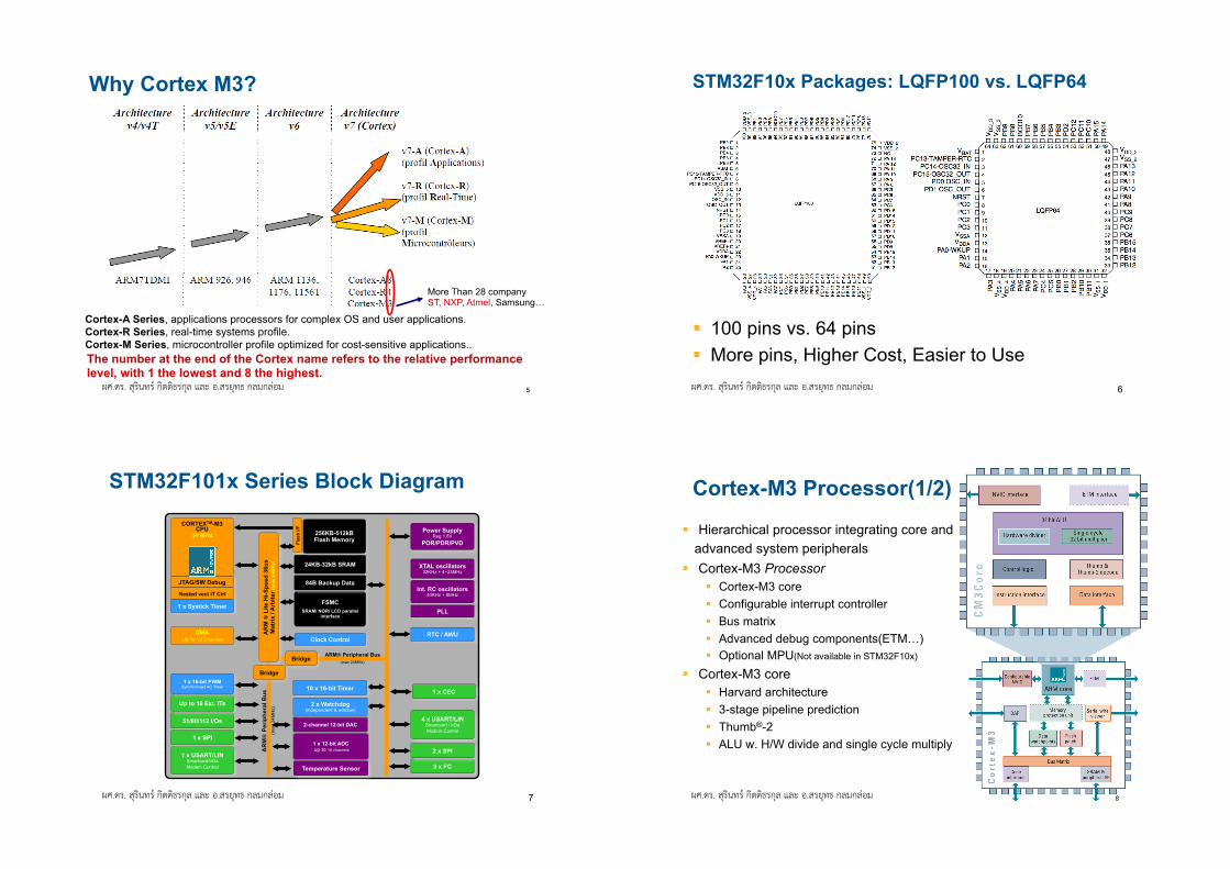
Why Cortex M3?
Cortex-A Series, applications processors for complex OS and user applications. Cortex-R Series, real-time systems profile. Cortex-M Series, microcontroller profile optimized for cost-sensitive applications.. The number at the end of the Cortex name refers to the relative performance level, with 1 the lowest and 8 the highest.
More Than 28 company ST, NXP, Atmel, Samsung…
5 ผศ.ดร. สุรินทร์ กิตติธรกุล และ อ.สรยุทธ กลมกล่อม
STM32F10x Packages: LQFP100 vs. LQFP64
! 100 pins vs. 64 pins ! More pins, Higher Cost, Easier to Use
6
ผศ.ดร. สุรินทร์ กิตติธรกุล และ อ.สรยุทธ กลมกล่อม
STM32F101x Series Block Diagram
CORTEXTM-M3 CPU
24 MHz
AR
M®
Per
iphe
ral B
us
(max
24M
Hz)
2 x I2C
4 x USART/LIN Smartcard / IrDa Modem Control
51/80/112 I/Os
Up to 16 Ext. ITs
FSMC SRAM/ NOR/ LCD parallel
interface
JTAG/SW Debug
Power Supply Reg 1.8V
POR/PDR/PVD
DMA up to 12 Channels
Nested vect IT Ctrl
1 x USART/LIN Smartcard/IrDa Modem Control
1 x SPI
Bridge
Bridge
1 x Systick Timer
AR
M ®
Lite
Hi-S
peed
36u
s M
atrix
/ A
rbite
r (m
ax 2
4MH
z)
RTC / AWU
ARM® Peripheral Bus (max 24MHz)
XTAL oscillators 32KHz + 4~25MHz
Int. RC oscillators 40KHz + 8MHz
PLL
24KB-32kB SRAM
Flas
h I/F
256KB-512kB Flash Memory
Clock Control
84B Backup Data
2-channel 12-bit DAC
1 x 12-bit ADC up to 16 channels
Temperature Sensor
2 x Watchdog (independent & window)
10 x 16-bit Timer
2 x SPI
1 x CEC 1 x 16-bit PWM
Synchronized AC Timer
7 ผศ.ดร. สุรินทร์ กิตติธรกุล และ อ.สรยุทธ กลมกล่อม
Cortex-M3 Processor(1/2)
! Hierarchical processor integrating core and advanced system peripherals
! Cortex-M3 Processor ! Cortex-M3 core ! Configurable interrupt controller ! Bus matrix ! Advanced debug components(ETM…) ! Optional MPU(Not available in STM32F10x)
! Cortex-M3 core ! Harvard architecture ! 3-stage pipeline prediction ! Thumb®-2 ! ALU w. H/W divide and single cycle multiply
8

ผศ.ดร. สุรินทร์ กิตติธรกุล และ อ.สรยุทธ กลมกล่อม
Cortex-M3 Processor(2/2)
SWD or JTAG
Breakpoints
Data Watchpoints & Trace
3-Stage Pipeline, Harvard Architecture, Thumb-2 ISA (or Thumb) 30K* Gates
1-240 Configurable Interrupts
with Configurable Priority Levels
Cortex M3 Total 60k* Gates
* Preliminary gate counts & power consumption based on initial implementation Gate Counts are based on TSMC 0.18 at 50MHz Optional ETM & MPU gate counts not included
Non Maskable Interrupt
9 ผศ.ดร. สุรินทร์ กิตติธรกุล และ อ.สรยุทธ กลมกล่อม
System Architecture ! Multiply possibilities of bus accesses to SRAM, Flash, Peripherals, DMA
! BusMatrix added to Harvard architecture allows parallel access
! Efficient DMA and Rapid data flow ! Direct path to SRAM through arbiter, guarantees alternating access
! Harvard architecture + BusMatrix allows Flash execution in parallel with DMA transfer
Buses are not overloaded with data movement tasks B
usM
atrix
D-bus
I-bus
CORTEX-M3
Master 1
GP-DMA Master 2
SRAM Slave
FLASH
Flas
h I
/F
AHB-APB2
AHB-APB1
AHB
Bridges
APB1
APB2
Arbiter Peripheral Bus APB1
Peripheral Bus APB2
10
ผศ.ดร. สุรินทร์ กิตติธรกุล และ อ.สรยุทธ กลมกล่อม
STM32F10x Block Diagram
11 ผศ.ดร. สุรินทร์ กิตติธรกุล และ อ.สรยุทธ กลมกล่อม
Cortex-M3 Processor Main Features ! ARM v7M Architecture ! Thumb-2 Instruction Set Architecture
! Mix of 16 and 32 bit instructions for very high code density
! Harvard architecture ! Separate I & D buses allow parallel instruction fetching & data storage
! Integrated Nested Vectored Interrupt Controller (NVIC) Vector Table is addresses.
! Integrated Bus Matrix
! Data memory management ! 3 Stage Pipeline
! Integrated System Timer (SysTick) for Real Time OS
12

ผศ.ดร. สุรินทร์ กิตติธรกุล และ อ.สรยุทธ กลมกล่อม
Cortex-M3 Memory Map
13 ผศ.ดร. สุรินทร์ กิตติธรกุล และ อ.สรยุทธ กลมกล่อม
Memory Mapping and Boot Modes
BOOT Mode Selection Pins Boot Mode Aliasing
BOOT1 BOOT0
x 0 User Flash
User Flash is selected as boot space
0 1 SystemMemory SystemMemory is selected as boot space
1 1 Embedded SRAM
Embedded SRAM is selected as boot space
! Boot modes: Depending on the Boot configuration - Embedded Flash Memory - System Memory - Embedded SRAM Memory is aliased at @0x00
! Addressable memory space of 4 GBytes ! RAM : up to 32 kBytes ! FLASH : up to 512 kBytes
! SystemMemory: contains the Bootloader used to re-program the FLASH through USART1.
CODE
SRAM
Peripherals
0x0000 0000
0x2000 0000
0x4000 0000
0xE010 0000
0xFFFF FFFF
Reserved
Reserved
Reserved
0x0800 0000
0x0801 FFFF
0x1FFF F000
0x1FFF F7FF
Flash
SystemMemory
Reserved
Reserved
Option Bytes 0x1FFF F800 0x1FFF F80F
Cortex-M3 internal
peripherals 0xE000 0000
0xE00F FFFF
Reserved
14
C"programming"for"embedded"microcontroller"systems."
Assumes&experience&with&assembly&language&programming."
V."P."Nelson"
Basic"C"program"structure"#include"<hidef.h>"#include"<MC9S12C32.h>"
/*"common"defines"and"macros"*/"/*"I/O"port/register"names/addresses"for"the"MC9S12C32"microcontroller"*/"
/*"Global"variables"–"accessible"by"all"funcLons"*/"int"count,"bob; "//global"(staLc)"variables"–"placed"in"RAM"
/*"FuncLon"definiLons*/"int"funcLon1(char"x)"{"int"i,j;"
//parameter"x"passed"to"the"funcLon,"funcLon"returns"an"integer"value"//local"(automaLc)"variables"–"allocated"to"stack"or"registers"
XX"instrucLons"to"implement"the"funcLon"}" /*"Main"program"*/"void"main(void)"{"
unsigned"char"sw1;"int"k;"
//local"(automatic)"variable"(stack"or"registers)"//local"(automatic)"variable"(stack"or"registers)"
/*"Initialization"section"*/"XX"instructions"to"initialize""variables,"I/O"ports,"devices,"function"registers"/*"Endless"loop"*/"while"(1)"{ "//Can"also"use:""for(;;)"{"XX"instructions"to"be"repeated"}"/*"repeat"forever"*/"}"
Declare"local"variables"
Initialize"variables/devices"
Body"of"the"program"

MC9S12C32"memory"map"0x0000"
0x0400"
0x0800"
0x4000"
0x8000"
0xC000"
16KB"Flash"Memory"
16KB"Flash"Memory"
16K"byte"Flash"EEPROM"[0x4000..0x7FFF]"for"program"code"&"constant""data"storage"
Interrupt"vectors:"[0xFF00..0xFFFF]"(Last"256"bytes"of"Flash"EEPROM)"
0x1000"Vacant"
2KB"RAM"
I/O"Registers" Control"registers"for"I/O"[0x0000..0x03FF]"
16K"byte"Flash"EEPROM"[0x4000..0x7FFF]"for"program"code"&"constant""data"storage"
2K"byte"RAM"[0x0800..0x0FFF]"for"variable"&"stack"storage"
0xFF00"
16KB"Vacant:"[0x8000..0xBFFF]"(Available"in"larger"devices"X""MC9S12C64/96/128)"
Vacant"
Vacant"
Address"
Microcontroller"“include"file”"• CodeWarrior&provides"a"deriva;ve<specific&“include"file”"for"
each" microcontroller," which" defines" memory" addresses"and" symbolic" labels" for" CPU" and" peripheral" funcLon"registers."
#include&<hidef.h>"#include&<MC9S12C32.h>"
/*&common&defines&and¯os&*/"/*&derivative&information&*/"
#pragma&LINK_INFO&DERIVATIVE&"MC9S12C32"" //&DDRA&and&PORTA&addresses&are&defined&in&MC9S12C32.h&void&main(void)&{"DDRA"="0xff;"PORTA"="0x55;"for(;;)&{}"
//"Set"direction"of"Port"A"as"output"//"Set"bits"of"Port"A"to"01010101"
/*&execute&forever&*/"}"
CodeWarrior&C"data"types"• Always"match"data"type"to"data"characterisLcs"• Variable"type"indicates"how"data"is"represented"
• #bits"determines"range"of"numeric"values"• signed/unsigned"determines"which"arithmeLc/
relaLonal"operators"are"to"be"used"by"the"compiler"• nonXnumeric"data"should"be"“unsigned”"
*"First"(black)"form"is"preferred"
Data$type$declara,on$*" Number$of$bits" Range$of$values"char$k;$$signed$char$k;" 8" =128..+127"
unsigned$char$k;" 8" 0..255"int$k;$$signed$int$k;$short$k;"signed$short$k;"
16" =32768..+32767"
unsigned$int$k;$unsigned$short$k;"
16" 0..65535"
Data"type"examples"• Read"bits"from"PORTA"(8"bits,"nonXnumeric)"
– unsigned&char&n; &n&=&PORTA;"• Read"TCNT"Lmer"value"(16Xbit"unsigned)"
– unsigned&int&t; &t&=&TCNT;"• Read"10Xbit"value"from"ADC"(unsigned)"
– unsigned&int&a; &a&=&ADC;"• System"control"value"range"[X1000…+1000]"
– int&ctrl;" ctrl&=&(x&+&y)*z;"• Loop"counter"for"100"program"loops"(unsigned)"
– unsigned&char&cnt;" for&(cnt&=&0;&cnt&<&20;&cnt++)&{"
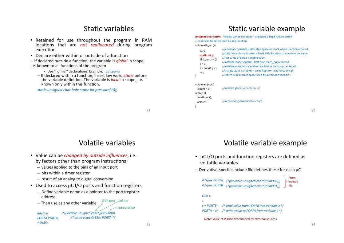
Static"variables"• Retained" for" use" throughout" the" program" in" RAM"locaLons" that" are" not& reallocated& during" program"execuLon."
• Declare"either"within"or"outside"of"a"funcLon"– If"declared"outside"a"funcLon,"the"variable"is"global&in"scope,"i.e."known"to"all"funcLons"of"the"program"
• Use"“normal”"declaraLons."Example:" int&count;"– If"declared"within"a"funcLon,"insert"key"word"sta;c&before"the"variable"definiLon."The"variable"is"local&in"scope,"i.e."known"only"within"this"funcLon."
sta;c&unsigned&char&bob;&sta;c&int&pressure[10];"
//automaLc"variable"–"allocated"space"on"stack"when"funcLon"entered"//staLc"variable"–"allocated"a"fixed"RAM"locaLon"to"maintain"the"value"//test"value"of"global"variable"count"//iniLalize"staLc"variable"j"first"Lme"math_op()"entered"//iniLalize"automaLc"variable"i"each"Lme"math_op()"entered"//change"staLc"variable"j"–"value"kept"for"next"funcLon"call"//return"&"deallocate"space"used"by"automaLc"variable"i"
Static"variable"example"unsigned$char$count;$$//global"variable"is"staLc"–"allocated"a"fixed"RAM"locaLon"//count"can"be"referenced"by"any"funcLon"void"math_op"()"{"
int"i;"sta,c$int$j;"if"(count"=="0)"j"="0;"i"="count;"j"="j"+"i;"
}"
void"main(void)"{"count"="0;"while"(1)"{"math_op();"count++;"}"
//initialize"global"variable"count"
//increment"global"variable"count"
Volatile"variables"• Value"can"be"changed&by&outside&influences,"i.e."by"factors"other"than"program"instrucLons"– values"applied"to"the"pins"of"an"input"port"– bits"within"a"Lmer"register"– result"of"an"analog"to"digital"conversion"
• Used"to"access"µC"I/O"ports"and"funcLon"registers"– Define"variable"name"as"a"pointer"to"the"port/register"address"
– Then"use"as"any"other"variable"
#define&PORTA&PORTA&=&0x55;"
(*((vola;le&unsigned&char*)(0x0000)))"/*&write&value&0x55to&PORTA&*/"
address"0000"
8Xbit"port "pointer"
Volatile"variable"example"• µC"I/O"ports"and"funcLon"registers"are"defined"as"voltaLle"variables"
– DerivaLveXspecific"include"file"defines"these"for"each"µC"
#define&PORTA"#define&PORTB"
(*((vola;le&unsigned&char*)(0x0000)))&(*((vola;le&unsigned&char*)(0x0001)))"
char&c;"…"c&=&PORTB;&PORTA&=&c;"
/*&read&value&from&PORTB&into&variable&c&*/"/*&write&value&to&PORTA&from&variable&c&*/"
From"include"file"
Note:"value"at"PORTB"determined"by"external"sources"

BitXparallel"logical"operators"Bit-parallel (bitwise) logical operators produce n-bit results of the corresponding logical operation: & (AND) | (OR) ^ (XOR) ~ (Complement)
C = A & B; (AND)
A 0 1 1 0 0 1 1 0 B 1 0 1 1 0 0 1 1 C 0 0 1 0 0 0 1 0
C = A | B; (OR)
A 0 1 1 0 0 1 0 0 B 0 0 0 1 0 0 0 0 C 0 1 1 1 0 1 0 0
C = A ^ B; (XOR)
A 0 1 1 0 0 1 0 0 B 1 0 1 1 0 0 1 1 C 1 1 0 1 0 1 1 1
B = ~A; A 0 1 1 0 0 1 0 0 (COMPLEMENT) B 1 0 0 1 1 0 1 1
Bit"set/reset/complement/test"• Use a “mask” to select bit(s) to be altered
Clear"selected"bit"of"A"
Set"selected"bit"of"A"
Complement"selected"bit"of"A"
Clear"all"but"the"selected"bit"of"A"
C = A & 0xFE; A a b c d e f g h 0xFE 1 1 1 1 1 1 1 0
C a b c d e f g 0
C = A & 0x01; A 0xFE
a 0 b 0 c 0 d 0 e 0 f 0 g 0 h 1
C 0 0 0 0 0 0 0 h C = A | 0x01; A a b c d e f g h
0x01 0 0 0 0 0 0 0 1 C a b c d e f g 1
C = A ^ 0x01; A a b c d e f g h 0x01 0 0 0 0 0 0 0 1
C a b c d e f g h’
Bit"examples"for"input/output"
• Create"a"“pulse”"on"bit"0"of"PORTA"(assume"bit"is"iniLally"0)"
PORTA&=&PORTA&|&0x01; &&//Force&bit&0&to&1&PORTA&=&PORTA&&&0xFE; &//Force&bit&0&to&0"
• Examples:"if&(&(PORTA&&&0x80)&!=&0&)&&//Or:&((PORTA&&&0x80)&==&0x80)"
bob();"c&=&PORTB&&&0x04;"if&((PORTA&&&0x01)&==&0)&PORTA&=&c&|&0x01;"
//&call&bob()&if&bit&7&of&PORTA&is&1"//&mask&all&but&bit&2&of&PORTB&value"//&test&bit&0&of&PORTA"//&write&c&to&PORTA&with&bit&0&set&to&1"
/***"PTT"X"Port"T"I/O"Register;"0x00000240"***/"typedef"union"{"byte"Byte;"struct"{"
}"Bits;"}"PTTSTR;"extern"volaLle"PTTSTR"_PTT"@(REG_BASE"+"0x00000240UL);"#define"PTT"#define"PTT_PTT0"#define"PTT_PTT1"#define"PTT_PTT2"#define"PTT_PTT3"#define"PTT_PTT4"#define"PTT_PTT5"#define"PTT_PTT6"#define"PTT_PTT7"
_PTT.Byte"_PTT.Bits.PTT0"_PTT.Bits.PTT1"_PTT.Bits.PTT2"_PTT.Bits.PTT3"_PTT.Bits.PTT4"_PTT.Bits.PTT5"_PTT.Bits.PTT6"_PTT.Bits.PTT7fine"TFLG1" _TFLG1.Byte"
Equivalent&C&statements:" PTT&=&PTT&|&0x01;&PTT_PTT0&=&1;" if&((PTT&&&0x04)&==&0x04)&If&(PTT_PTT2&==&1)"
CodeWarrior"include"file"defines"µC"registers"as"structures"of"bits,"allowing"access"to"individual"register"bits."(Read"file"to"view"names.)" “byte”"is"defined"as"“unsigned"char”"
byte"PTT0" :1;" /*"Port"T"Bit"0"*/"byte"PTT1" :1;" /*"Port"T"Bit"1"*/"byte"PTT2" :1;" /*"Port"T"Bit"2"*/"byte"PTT3" :1;" /*"Port"T"Bit"3"*/"byte"PTT4" :1;" /*"Port"T"Bit"4"*/"byte"PTT5" :1;" /*"Port"T"Bit"5"*/"byte"PTT6" :1;" /*"Port"T"Bit"6"*/"byte"PTT7" :1;" /*"Port"T"Bit"7"*/"

Example:"I/O"port"bits"
unsigned"char"sw;"sw"="PORTB;"sw"="PORTB"&"0x10;"
Switch"connected"to"bit"4"of"PORTB"//8Xbit"unsigned"variable"//"sw"="hgfedcba"//"sw"="000e0000""(mask"all"but"bit"4)"//"Result"is"sw"="00000000"or"00010000"//"NEVER"TRUE"for"above"sw,"which"is"000e0000"//"TRUE"if"e=1"(bit"4"in"result"of"PORTB"&"0x10)"//"TRUE"if"e=0"in"PORTB"&"0x10"(sw=00000000)"//"TRUE"if"e=1"in"PORTB"&"0x10"(sw=00010000)"//"Write"to"8"bits"of"PORTB;"result"is"01011010"//"Sets"only"bit"e=0"in"PORTB""(PORTB"now"hgf0dcba)"//"TRUE"if"e=1"(bit"4"of"PORTB)"//"Mismatch:"comparing"bit"to"byte"
if" (sw" ==" 0x01)" if" (sw"=="0x10)"if"(sw"=="0)"if"(sw"!="0)"PORTB"="0x5a;"PORTB_BIT4"="0;"if"(PORTB_BIT4"=="1)"if"(PORTB_BIT4"=="sw)"
7" 6" 5" 4" 3" 2" 1" 0"
PORTB"h" g" f" e" d" c" b" a"
Shift"operators"Shift operators: x >> y (right shift operand x by y bit positions) x << y (left shift operand x by y bit positions) Vacated bits are filled with 0’s. Shift right/left fast way to multiply/divide by power of 2
(Right shift 2 bits) B 0 0 1 0 1 1 0 1
B = ‘1’; C = ‘5’; D = (B <<
(B
B = 0 0 1 1 0 0 0 1 (ASCII C = 0 0 1 1 0 1 0 1 (ASCII
0x31) 0x35)
4) | (C & 0x0F); << 4) = 0 0 0 1 0 0 0 0
B = A << 3; A 1 0 1 0 1 1 0 1 (Left shift 3 bits) B 0 1 1 0 1 0 0 0 B = A >> 2; A 1 0 1 1 0 1 0 1
(C & 0x0F) = 0 0 0 0 0 1 0 1 D = 0 0 0 1 0 1 0 1 (Packed BCD 0x15)
WHILE"loop"structure"
• Repeat"a"set"of"statements"(a"“loop”)"as"long"as"some"condiLon"is"met"
while&(a&<&b)"{"statement&s1;&statement&s2;"…."}"
a"<"b"?" Yes"
No"
S1;"S2;"…"
“loop”"through"these"statements"while"a"<"b"
Something"must"eventually"cause"a">="b,"to"exit"the"loop"
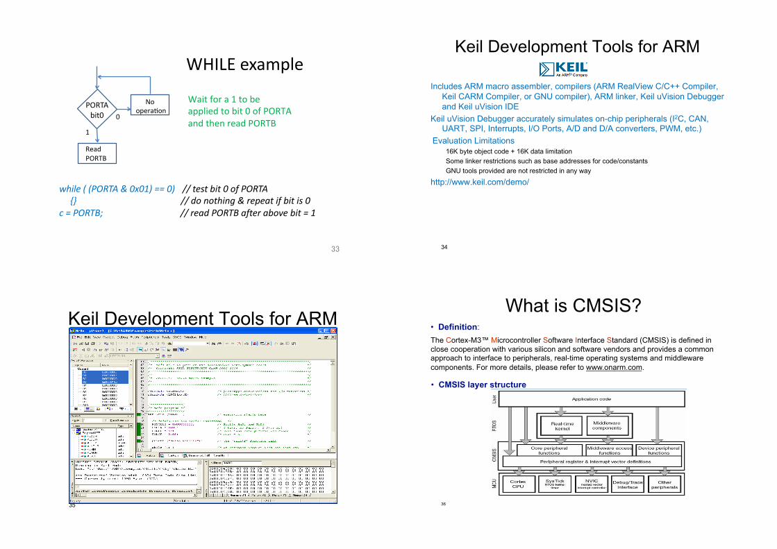
WHILE"example"
while&(&(PORTA&&&0x01)&==&0)"{}"
c&=&PORTB;"
WHILE"example"
while&(&(PORTA&&&0x01)&==&0)"{}"
c&=&PORTB;"
//&test&bit&0&of&PORTA"//&do¬hing&&&repeat&if&bit&is&0"//&read&PORTB&after&above&bit&=&1"
PORTA"bit0" 0"
1" Read"PORTB"
No"operaLon"
Wait"for"a"1"to"be"applied"to"bit"0"of"PORTA"and"then"read"PORTB"
Keil Development Tools for ARM
Includes ARM macro assembler, compilers (ARM RealView C/C++ Compiler, Keil CARM Compiler, or GNU compiler), ARM linker, Keil uVision Debugger and Keil uVision IDE
Keil uVision Debugger accurately simulates on-chip peripherals (I2C, CAN, UART, SPI, Interrupts, I/O Ports, A/D and D/A converters, PWM, etc.)
Evaluation Limitations 16K byte object code + 16K data limitation Some linker restrictions such as base addresses for code/constants GNU tools provided are not restricted in any way
http://www.keil.com/demo/
34
Keil Development Tools for ARM
35 36
What is CMSIS? • Definition: The Cortex-M3™ Microcontroller Software Interface Standard (CMSIS) is defined in close cooperation with various silicon and software vendors and provides a common approach to interface to peripherals, real-time operating systems and middleware components. For more details, please refer to www.onarm.com.
• CMSIS layer structure

37
Package organization
38
STM32 Firmware Library User Manual
Main page
39
STM32 Firmware Library User Manual
40
STM32F10xxx standard peripheral library architecture
Cortex-M3 exceptions
- STM32 interrupt IRQ list/ Specific options for the Cortex-M3 core - STM32 peripheral memory mapping and physical register address definition - Configuration options …
Peripheral header file
Include NVIC and SysTick drivers
Low-level & API functions to Perform basic operations offered by the peripheral
User application

41
Coding conventions All firmware is coded in ANSI-C
Strict ANSI-C for all library peripheral files
Relaxed ANSI-C for projects & Examples files.
PPP is used to reference any peripheral acronym, e.g. TIM for Timer.
Registers & Structures FW library registers have the same names as in STM32F10x
Datasheet & reference manual.
All registers hardware accesses are performed through a C structures :
Improve code re-use : e.g. the same structure to handle and initialize 3 USARTs.
42
Using the Library (1/4) 1) Before configuring a peripheral, you have to enable its clock by calling one of the
following functions: RCC_AHBPeriphClockCmd(RCC_AHBPeriph_PPPx , ENABLE); RCC_APB2PeriphClockCmd(RCC_APB2Periph_PPPx , ENABLE); RCC_APB1PeriphClockCmd(RCC_APB1Periph_PPPx , ENABLE);
2) PPP_DeInit(..) function can be used to set all PPP’s peripheral registers to their reset values:
PPP_DeInit(PPPx);
3) If after peripheral configuration, the user wants to modify one or more peripheral settings he should proceed as following:
PPP_InitStucture.memberX = valX; PPP_InitStructure.memberY = valY; PPP_Init(PPPx, &PPP_InitStructure);
43
Using the Library (2/4) At this stage the PPP peripheral is initialized and can be enabled by making a
call to PPP_Cmd(..) function: PPP_Cmd(PPPx, ENABLE); Note: This function is used only for communication peripherals like UART,
SPI, … To access the functionality of the PPP peripheral, the user can use a set of
dedicated functions. These functions are specific to the peripheral and for more details refer to STM32F10x Firmware Library User Manual.
Example of GPIO Functions available
44
Using the Library (3/4) UART1 configuration example : /* Enable USART1 Clock */ RCC_APB2PeriphClockCmd( USART1, ENABLE ); /* set all UART1’s peripheral registers to their reset values */ USART_DeInit( USART1 ) ; /* USART1 configuration ------------------------------------------------------*/ /* USART1 configured as follow: - BaudRate = 19200 baud - Word Length = 8 Bits - One Stop Bit - Even parity - Hardware flow control disabled (RTS and CTS signals) - Receive and transmit enabled */ USART_InitStructure.USART_BaudRate = 9600; USART_InitStructure.USART_WordLength = USART_WordLength_8b; USART_InitStructure.USART_StopBits = USART_StopBits_1; USART_InitStructure.USART_Parity = USART_Parity_Even; USART_InitStructure.USART_HardwareFlowControl = USART_HardwareFlowControl_None; USART_InitStructure.USART_Mode = USART_Mode_Rx | USART_Mode_Tx; /* Configure USART1 */ USART_Init( USART1, &USART_InitStructure); /* Enable USART1 */ USART_Cmd( USART1, ENABLE );
USART 1 is ready now …
45
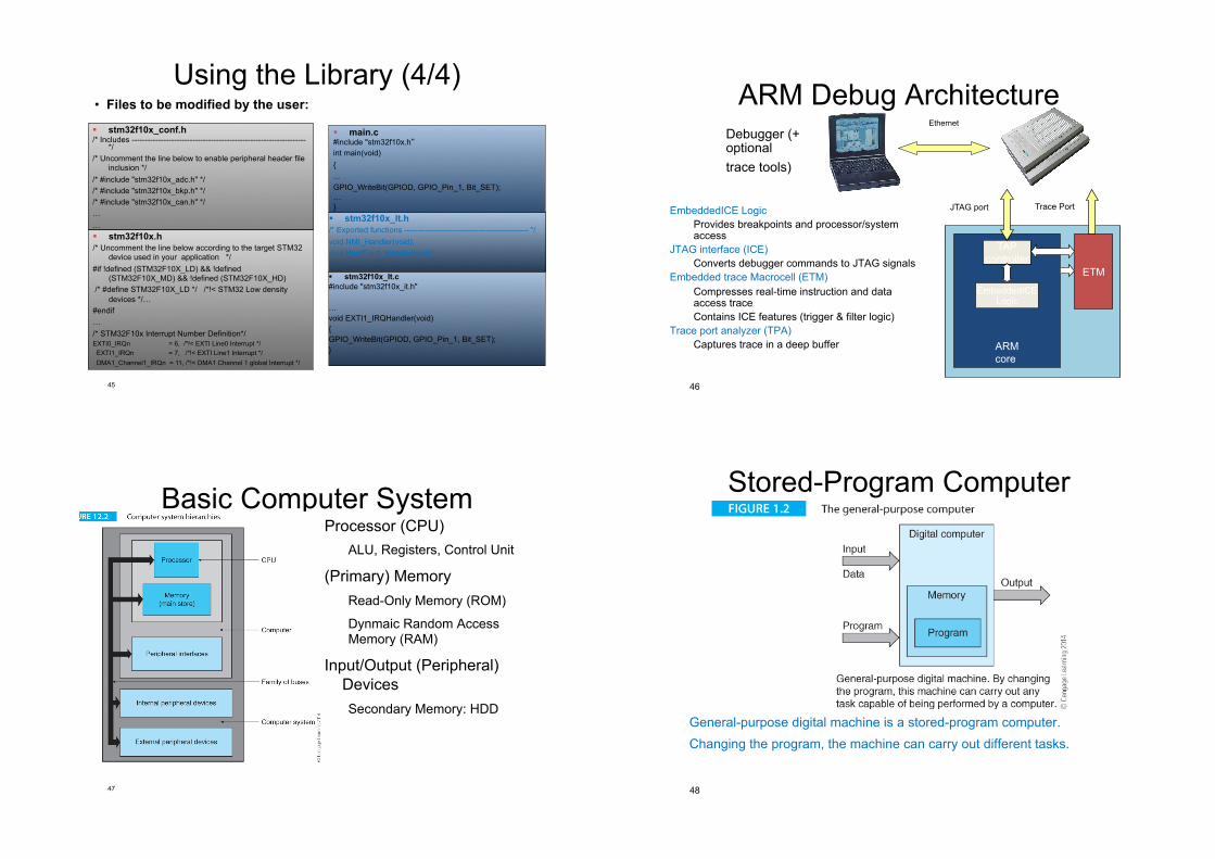
Using the Library (4/4)
! stm32f10x_It.h /* Exported functions ----------------------------------------------- */ void NMI_Handler(void); void HardFault_Handler(void); … ! stm32f10x_It.c #include "stm32f10x_it.h" … void EXTI1_IRQHandler(void) { GPIO_WriteBit(GPIOD, GPIO_Pin_1, Bit_SET); }
! main.c #include "stm32f10x.h int main(void) { ... GPIO_WriteBit(GPIOD, GPIO_Pin_1, Bit_SET); … }
! stm32f10x_conf.h /* Includes ------------------------------------------------------------------
*/ /* Uncomment the line below to enable peripheral header file
inclusion */ /* #include "stm32f10x_adc.h" */ /* #include "stm32f10x_bkp.h" */ /* #include "stm32f10x_can.h" */ … … ! stm32f10x.h /* Uncomment the line below according to the target STM32
device used in your application */ #if !defined (STM32F10X_LD) && !defined
(STM32F10X_MD) && !defined (STM32F10X_HD) /* #define STM32F10X_LD */ /*!< STM32 Low density
devices */… #endif … /* STM32F10x Interrupt Number Definition*/ EXTI0_IRQn = 6, /*!< EXTI Line0 Interrupt */ EXTI1_IRQn = 7, /*!< EXTI Line1 Interrupt */ DMA1_Channel1_IRQn = 11, /*!< DMA1 Channel 1 global Interrupt */
• Files to be modified by the user: ARM Debug Architecture
ARM core
ETM
TAP controller
Trace Port JTAG port
Ethernet Debugger (+ optional trace tools)
EmbeddedICE Logic Provides breakpoints and processor/system access
JTAG interface (ICE) Converts debugger commands to JTAG signals
Embedded trace Macrocell (ETM) Compresses real-time instruction and data access trace Contains ICE features (trigger & filter logic)
Trace port analyzer (TPA) Captures trace in a deep buffer
EmbeddedICE Logic
46
Basic Computer System Processor (CPU)
ALU, Registers, Control Unit
(Primary) Memory Read-Only Memory (ROM)
Dynmaic Random Access Memory (RAM)
Input/Output (Peripheral) Devices Secondary Memory: HDD
47
Stored-Program Computer
General-purpose digital machine is a stored-program computer. Changing the program, the machine can carry out different tasks.
48
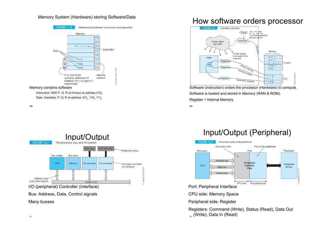
Memory System (Hardware) storing Software/Data
Memory contains software Instruction: ADD P, Q, R (in binary) at address 0102
Data: Variables: P, Q, R at address 1012, 1102, 1112
49
How software orders processor (hardware)
Software (instruction) orders the processor (Hardware) to compute. Software is loaded and stored in Memory (RAM & ROM).
Register = Internal Memory
50
Input/Output
I/O (peripheral) Controller (interface)
Bus: Address, Data, Control signals
Many busses
51
Input/Output (Peripheral)
Port: Peripheral Interface
CPU side: Memory Space
Peripheral side: Register
Registers: Command (Write), Status (Read), Data Out (Write), Data In (Read)
52

![AM1808 ARM Microprocessor datasheet (Rev. E) · Title: AM1808 ARM Microprocessor datasheet (Rev. E) Author: Texas Instruments, Incorporated [SPRS653,E ] Subject: Data Manual on Single](https://img.dokumen.tips/doc/110x75/60c34054293bc734be46413b/am1808-arm-microprocessor-datasheet-rev-e-title-am1808-arm-microprocessor-datasheet.jpg)