Embed Size (px)
Citation preview

© 2012 ANSYS, Inc. November 20, 2012 1 Release 14.5
14. 5 Release
Introduction to ANSYS DesignModeler
Lecture 10 Lines and Surfaces (Concept Modeling)
© 2012 ANSYS, Inc. November 20, 2012 2 Release 14.5
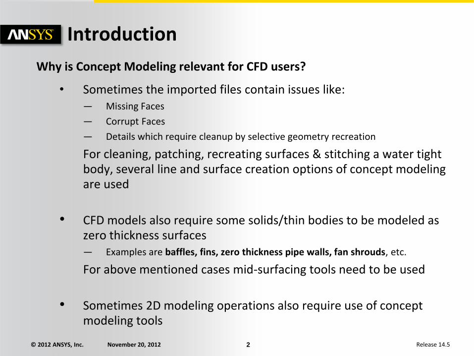
Why is Concept Modeling relevant for CFD users?
• Sometimes the imported files contain issues like: — Missing Faces
— Corrupt Faces
— Details which require cleanup by selective geometry recreation
For cleaning, patching, recreating surfaces & stitching a water tight body, several line and surface creation options of concept modeling are used
• CFD models also require some solids/thin bodies to be modeled as zero thickness surfaces — Examples are baffles, fins, zero thickness pipe walls, fan shrouds, etc.
For above mentioned cases mid-surfacing tools need to be used
• Sometimes 2D modeling operations also require use of concept modeling tools
Introduction

© 2012 ANSYS, Inc. November 20, 2012 3 Release 14.5
• The features in the Concept menu are predominantly used to create and modify line bodies and/or surface bodies
• For modeling lines and surfaces, you can also:
– Create line or surface bodies using the features in the Draw toolbox to design a 2D sketch and/or generate a 3D model
– Use the Import external geometry file feature
– Mid-surfaces can be used for converting a body into zero thickness surface (e.g. Fins, Baffles, Fan shroud, etc.)
– Other tools like Thin, Extrude, etc.
• Line bodies
– Lines from points
– Lines from sketches
– Lines from edges
• Surface bodies
– Surfaces from line bodies
– Surfaces from sketches
– Surfaces from 3D edges
– Mid-surface
– Joint
Lines and Surfaces

© 2012 ANSYS, Inc. November 20, 2012 4 Release 14.5
Creating Line Bodies (1) Lines From Points
[Main Menu] Concept Lines From Points – Points can be any 2D sketch points, 3D model vertices or Point Feature (PF) points.
– A point segment is a straight line connecting two selected points.
– The feature can produce multiple Line Bodies, depending on the connectivity of the chosen point segments.
– The Operation field allows Add or Add Frozen choices for line bodies.
Point 1
Point 2
Line Body

© 2012 ANSYS, Inc. November 20, 2012 5 Release 14.5
Creating Line Bodies (2) Lines From Sketches
[Main Menu] Concept Lines From Sketches – Line bodies created based on sketches and planes from faces
– Multiple Line Bodies may be created depending on the connectivity of the edges within the base objects
– Select sketches or planes in the feature tree then “Apply” in the detail window
– Multiple sketches, planes, and combinations of sketches and planes can be used as the base object for the creation of line bodies

© 2012 ANSYS, Inc. November 20, 2012 6 Release 14.5
Creating Line Bodies (3) Lines From Edges
[Main Menu] Concept Lines From Edges – Creates line bodies based on existing 2D and 3D model edges
– Can produce multiple line bodies depending on the connectivity of the selected edges and faces
– Can select edges and/or faces through two fields in the detail window then “Apply”
Line Bodies

© 2012 ANSYS, Inc. November 20, 2012 7 Release 14.5
Split Edges Split Line Body
[Main Menu] Concept Split Edges – Splits line body edges into two pieces
– Split location is controlled by the Fraction property (e.g. 0.5 = split in half).
– Other Options:
• Split by Delta: Distance between each split is given by Delta along the edge
• Split by N: Number of Divisions of the Edge Selected line Fraction =
0.5 Fraction =
0.25

© 2012 ANSYS, Inc. November 20, 2012 8 Release 14.5
Cross Sections (1) Cross Sections
– Cross sections are attributes assigned to line bodies to define beam properties in the FE simulation
– In DM, cross sections are represented by sketches and are controlled by a set of dimensions
• Note: Design-Modeler uses a different coordinate system for cross sections than the one used in the ANSYS environment (described later)

© 2012 ANSYS, Inc. November 20, 2012 9 Release 14.5
Cross Sections (2) • Cross sections are selected from the Concept menu
• A cross section branch is inserted in the tree where each chosen cross section is listed
Cross Sections in
Tree Outline
Concept Menu
List of Cross
Sections

© 2012 ANSYS, Inc. November 20, 2012 10 Release 14.5
Cross Sections (3)
Assigning a cross section to a line body: – Highlight the line body in the Tree
– A cross section property appears in the detail window
– Click in this field and choose the desired cross section from the drop down list

© 2012 ANSYS, Inc. November 20, 2012 11 Release 14.5
Surfaces From Edges (1) Surfaces From Edges
[Main Menu] Concept Surfaces from Edges – Creates surface body using line body edges as the boundary
– Line body edges must form non-intersecting closed loops
– Each closed loop creates a frozen Surface Body
– The loops should form a shape such that a simple surface can be inserted into the model:
• Planes, cylinders, tori, cones, spheres and simple twisted surfaces
Planar surface Non-planar
surface
Details window:
• Flip surface normals
• Input thickness which will be
transferred to the FE model

© 2012 ANSYS, Inc. November 20, 2012 12 Release 14.5
Surfaces From Edges (2)
• Creates surfaces from existing body edges
• Can be solid or line body edges
• Edges must produce non-intersecting closed loops
Existing solid body edges are
selected for new surface boundary. New, frozen, surface body generated
(note, solid body is hidden).

© 2012 ANSYS, Inc. November 20, 2012 13 Release 14.5
Surfaces From Edges (3)
• A line body with no cross section can be used to tie together surface models
• In this case, the line body acts merely as a mechanism to insure a continuous mesh at the surface boundaries
Line Body (no cross section) Result is continuous FE mesh
at surface interface
2 Surface Bodies

© 2012 ANSYS, Inc. November 20, 2012 14 Release 14.5
Surfaces From Sketches Surfaces From Sketches
[Main Menu] Concept Surfaces from Sketches – Creates surface bodies using sketches as boundaries (single or multiple sketches are OK) – Base sketches must be closed profiles which are not self intersecting – May choose to “Add” or “Add Frozen” operations – Can reverse normal direction “No” in Orient With Plane Normal field – Can enter thickness which will be used in creating the FE model

© 2012 ANSYS, Inc. November 20, 2012 15 Release 14.5
Mid-Surface
• Extracts surface body that is midway between existing solid body faces
• Two Options:
– Manual: Operates only on user specified face pairs
– Automatic: Provides option to search for other matching face pairs
Details View of Mid-Surface
Mid-Surface created
for a pipe geometry
© 2012 ANSYS, Inc. November 20, 2012 16 Release 14.5
Mid-Surface: Manual (1)
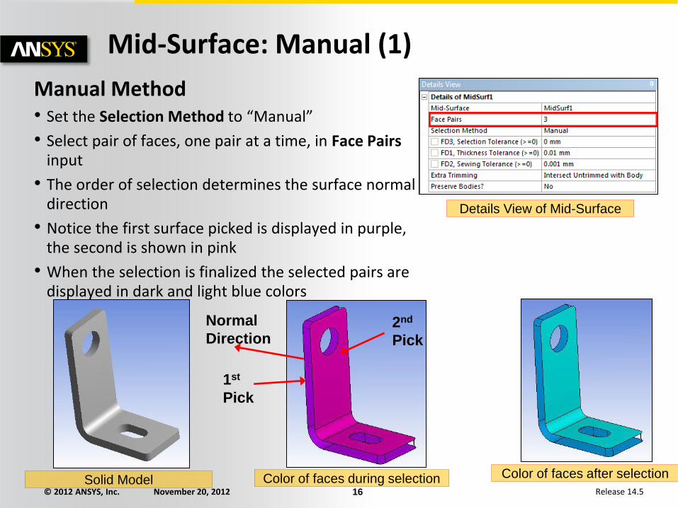
Manual Method • Set the Selection Method to “Manual”
• Select pair of faces, one pair at a time, in Face Pairs input
• The order of selection determines the surface normal direction
• Notice the first surface picked is displayed in purple, the second is shown in pink
• When the selection is finalized the selected pairs are displayed in dark and light blue colors
Details View of Mid-Surface
2nd
Pick
1st
Pick
Normal
Direction
Solid Model Color of faces during selection Color of faces after selection

© 2012 ANSYS, Inc. November 20, 2012 17 Release 14.5
Mid-Surface: Manual (2)
• Multiple surface pairs may be selected for a single mid-surface operation, however they must be selected as opposing pairs
• The correct order of selection of faces for the previous example can be as in the image shown on right hand side here
• Adjacent face pairs will be grouped together if within the “Thickness Tolerance” (see below)
Order of face selection
3
1
5
4
6
2
T1 T2
If │T1 – T2│ < Thickness Tolerance: surfaces
are grouped

© 2012 ANSYS, Inc. November 20, 2012 18 Release 14.5
Mid-Surface: Automatic (1) Automatic Method
• Switching the Selection Method from “Manual” to “Automatic” exposes several additional options
– Bodies to search: Limits search to visible bodies, selected bodies or all bodies
– Minimum and maximum threshold sets search range (thickness) for face pairs
• Options like Extra Trimming are very useful with “Automatic” method
– Provides options for situations where trimming problems with surface bodies occur
• Preserve Bodies? allows you to save the solid bodies from which surfaces are created (default is No)
© 2012 ANSYS, Inc. November 20, 2012 19 Release 14.5
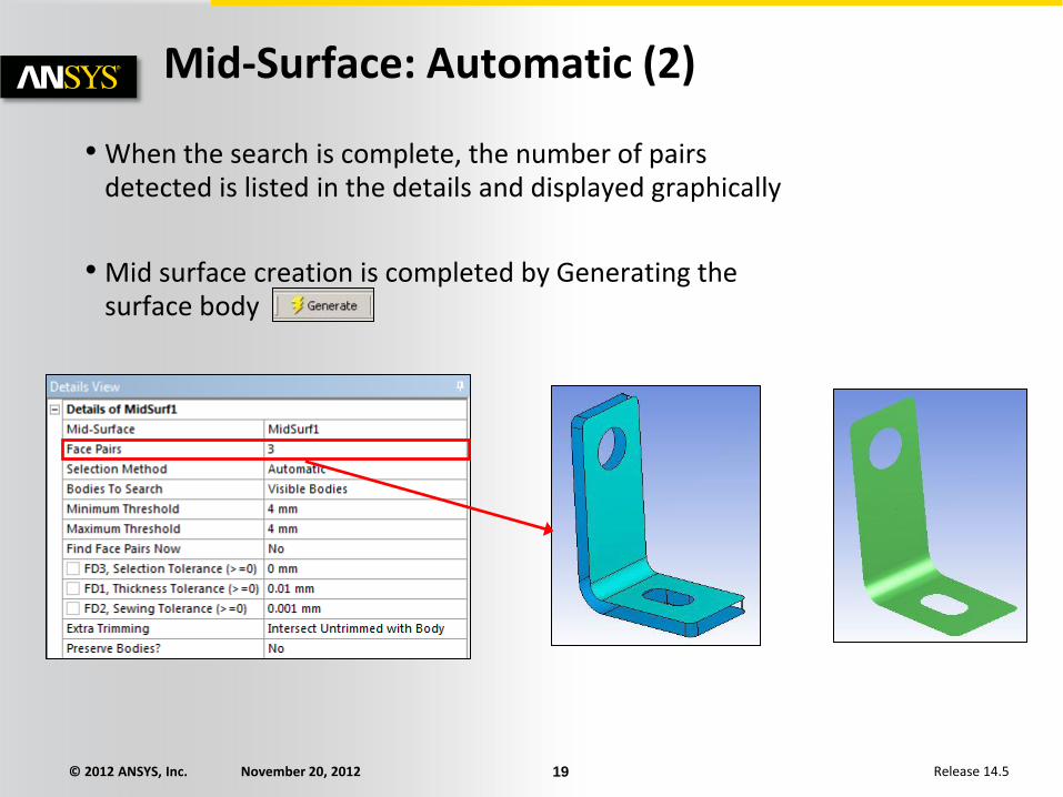
• When the search is complete, the number of pairs detected is listed in the details and displayed graphically
• Mid surface creation is completed by Generating the surface body
Mid-Surface: Automatic (2)

© 2012 ANSYS, Inc. November 20, 2012 20 Release 14.5
• Joins surface bodies together such that their contact regions share common edge
– Prerequisite for conformal meshes
• Takes two or more surface bodies as input
• Imprints edges on all bodies where they make contact
Joint
Details View
of Joint
Surface bodies to be Joined Surface bodies after Joint

© 2012 ANSYS, Inc. November 20, 2012 21 Release 14.5
• Edge Joints are the glue that holds together bodies where a continuous mesh is desired
• Creating surface and/or line multi-body parts with coincident edges results in automatic creation of edge joints
• Joints can be created manually ([Main Menu] Tools Joint) where no coincident topology exists
Edge Joints (1)

© 2012 ANSYS, Inc. November 20, 2012 22 Release 14.5
• Edge Joints can be viewed by turning on the Edge Joints option in the View menu.
• Edge joints are displayed in either blue or red.
– Blue: edge joint is contained in properly defined multi-body part
– Red: edge joint not grouped into the same part
Edge Joints (2)
No Edge Joint With Edge Joint