Embed Size (px)
Citation preview

EDM
IntroductionProtecting the surface integrity of the cavity is one of the most critical facets of EDMing today. The integrity of the surface finish in the cavity is deter-mined by the formation of the thermal altered lay-ers created by the EDM process. The EDM process, as we all know involves the transference of a con-trolled electrical discharge between an electrode and the workpiece. The current applied to the workpiece during this discharge melts and vaporiz-es the metal therefore creating the thermal altered layers of the cavity.
Before we can understand how the EDM process affects the integrity of the mold surface, we must first understand the various layers of the cavity that are thermally altered by this process. The EDM process changes not only the surface of the workmetal, but also the subsurface layers as well.
Thermally Altered LayersThe various layers affected by the EDM process have been referred to by many names. The culmi-nation of these layers will be referred to as the altered metal zone. As you can see from Figure 1, the altered metal zone is comprised of two ther-mally affected sub-layers of material know as the recast or white layer and the heat affected annealed layer.
The white layer is the layer that has been heated to the point of a molten state, but not quite hot enough to be ejected into the gap and be flushed away. The EDM process has actually altered the metallurgical structure and characteristics in this layer as it is formed by the unexpelled molten metal being rapidly cooled by the dielectric fluid during the flushing process and resolidifying in the cavity. This layer does include some expelled parti-cles that have solidified and have been re-deposit-ed on the surface prior to being flushed out of the gap. The white layer is densely infiltrated with car-bon to the point that its structure is distinctly dif-ferent than that of the base material. This carbon enrichment occurs when the hydrocarbons of the electrode and dielectric fluid break down during the EDM process and impenetrate into the white layer while the material is essentially in its molten
EDM EFFECT ON SURFACE INTEGRITY
Author: Jerry Mercer
state. Figure 2 shows a breakdown of the elemen-tal analysis of a base material prior to being EDMed and the white layer after EDM. As can be easily seen, the carbon content after the EDM pro-cess is much greater than the base material prior to EDM.
Beneath the white layer is the heat affected zone. This layer is minimally affected by the carbon enrichment of the white layer and has only been heated, but not to a point to reach melting temper-ature. At this point, the heat affected zone retains the metallurgical structure of the parent material as the temperature absorbed is not to the level to change the structure. Below the heat affected zone is the parent material and this area is unaffected by the EDM process.
Redeposited Layer
White Layer
Annealed Layer
Unaffected Working Material
Figure 1
Carbon Enrichment of White Layer
C Si Mn Cr Mo Fe
Base Material
1.55 .055 0.3 0.03 .02
Rem
aind
er
Other
After EDM
19.09 12.25 2.14
Rem
aind
er 0.43
Figure 2

2
EDM EFFECT ON SURFACE INTEGRITY
MicrocrackingA major concern for moldmakers is the amount of microcracks present in the mold. As seen in Figure 3, microcracking is extremely prominent in the white layer. If this layer is too thick or is not removed by finer EDM finishes or polishing, the effects of this microcracking can cause premature failure of the part in some applications. Furthermore, it has been known that the existence of these microcracks lowers the corrosion and fatigue resitstance of the material. Therefore, sur-face integrity should be the primary consideration when evaluating the performance of the EDM tech-nique and the prime objective of EDM machining must be to establish the condition which suppress-es this formation. The microcracks produced by the EDM process is the result of thermal stresses created during the on-time phase of the EDM cycle. The depth of the microcracking is partially controlled by the EDM program and it goes without saying that as the spark intensity increases so does the depth of the white layer. This also facilitates an increase in the number and size of microcracks present in the cavity. Obviously, the surface integri-ty affected by the EDM process can be controlled by the technologies of today’s EDM power supply. The specific parameters that affect the surface integrity are voltage, amperage, on-time and duty cycle. These parameters can be manipulated to optimize efficiencies in the roughing, semi-finish-ing and finishing stages and control the surface integrity accordingly.
Since the EDM discharge produces the white layer and microcracking, it is safe to say that the depth will be as thick (or as thin) as the intensity of the spark energy. As the spark energy is reduced, such as we see in changing from a roughing condition to a finishing condition, the depth of the white layer and appropriately enough, the cracking will also be reduced.
Workpiece CharacteristicsThe spark intensity is not the only determining fac-tor affecting the surface integrity. This is also dependent on the thermal conductivity of the workmetal. High thermally conductive metals will usually have a smaller white layer and less micro-cracking than a lower conductive material. The reason for this is due to the energy dissipation throughout the surface of the higher conductive materials. In this case, we can expect for a copper alloy material to have a thinner affected layer with less cracking due to its high thermal conductivity and ductile nature. Contrary to this, a material with a low conductivity value, such as tool steel can be expected to have a thicker affected layer with more cracking because the spark intensity remains in the spark area longer before the materi-al can dissipate the energy to the surrounding areas.
Burning carbide creates another concern for the EDMer as this material is very brittle and therefore exhibits higher levels of thermal cracking than other materials. Some consider this material to be highly conductive; however carbide is comprised of tungsten carbide or silicon carbide particles held together with a cobalt binder. It is this binder that has the high conductivity value and is the area that is affected by the EDM process instead of the car-bide itself. The spark energy disintegrates the binder and releases the carbide particles into the gap.
Surface Finish and IntegritySurface finish and integrity are two different facets of the cavity quality, but both play an important part in the characteristics of the mold. Much as the machine parameters affect the integrity of the sub-layers of the cavity, they also affect the surface finish. Figure 4 shows how the amperage and on-time affect the surface finish during the EDM pro-cess.
Another important factor in controlling the surface finish that is often overlooked is the type of elec-trode material being used in the application. In terms of the sub-surface integrity of the cavity, the type of electrode has little effect. Where the elec-trode material does play an important role is the finish on the cavity’s surface itself. The surface finish of the cavity is an area where there is oppor-tunity to reduce manufacturing costs and delivery time while still being able to provide a quality mold. A mold with a fine EDM finish can be used
Cross section illustrating microcracks in the white layer
Figure 3 - Cross Section illustrating microcracks in the white layer.

right out of the tank while one that needs polishing or etching requires added costs as these processes are carried out. A fine EDM finish is achieved by using a high frequency EDM program with low amperages and short on-times. The quality of the electrode material goes hand-in-hand with the EDM program to achieve the desired results. Taking the EDM program out of the equation, the cavity surface will reflect the quality of the elec-trode material used to finish the cavity.
The material particle size and corresponding pore size plays a significant role in the materials ability to produce a fine finish. If the structure of the electrode material is not capable of producing the specified surface finish, the EDM machine will continue to run without ever reaching the desired surface finish.
Figure 5 shows the surface finish of two materials at the same machine parameters. As can be seen, the material with the finer material structure pro-vides the smoother surface finish and therefore will require less polishing to achieve the desired finish results.
An electrode material with a poor microstructure – such as large or irregular particle shapes will wear unevenly causing the cavity to also have uneven surface areas. This situation is especially critical on multi-cavity molds where the surface finish is required to be consistent on all cavities. When using a graphite electrode material, strict caution should be taken to ensure consistent quality for all electrodes. Because graphite grades from different manufacturers will wear differently, it is possible that the EDM machine may not provide the specif-ic programmed surface finish. This is most often seen when molds are produced using different types of electrode materials or makes of EDM machines.
Know the Limitations The surface finish and surface integrity are two facets that affect the quality of the mold, it is imperative that the EDMer know the limitations of these areas. Although most current EDM machines produce very fine finishes using standard technolo-gies integrated within the machine, a common practice is to override these technologies in order to gain optimization of the process. Without know-ing how to calculate the depth of the white layer, or how the electrode material affects the EDM pro-cess, the attempt to optimize the process may actually result in declining performance or failure to produce a quality part.
Electrode MaterialTo improve the potential for success in quality mold production, moldmakers need to understand some specific characteristics of the electrode material as well as certain facets of the EDM pro-cess that affect surface finish and integrity. An understanding of these components will signifi-cantly improve the potential of success in produc-ing a quality mold.
There have been many articles written about the various types of electrode material available for EDM. The majority of these articles focus on the microstructure of the material and how this struc-ture— along with the particle size of the materi-al—plays a part in the final EDM surface finish. While the importance of the particle size and microstructure of the electrode material should not be discounted, there is another characteristic that should be considered. This is the Electrical Resistivity (ER) value of the electrode.
3
EDM EFFECT ON SURFACE INTEGRITY
Figure 4
Figure 5
0
100
200
300
400
500
600
700
2µS 12µS 50µS 200µS
15
25
35
55
MicrosecondsOn-Time
Surfa
ceFinish
Raµ-inch
Amperage
EDMEffectonSurfaceFinishToolSteel;PositivePolarity
0
100
200
300
400
500
600
700
2 12 25 50 100 200
Surf
ace
Fini
ch R
a m
icro
inch
On-Times Microseconds
Superfine
Ultrafine
Electrode Material Effect on Surface FinishTool Steel; Positive Polarity @ 35 Amps

The electrical resistivity of a material is the prop-erty that determines the resistance to the flow of an electrical current as it passes through the elec-trode. Materials with lower ER values are better conductors and allow more energy to be applied into the EDM cut. Conversely, materials with high-er ER values seem to retain a greater amount of the energy within the electrode and increase the potential of overheating and increasing the over-burn.
While graphite is inherently resistant to the cur-rent being applied to the electrode, the varying porosity within the microstructure plays a large role in the amount of electrical resistivity of a spe-cific material. The porosity of the material greatly affects the electrical resistivity as these pores are pockets of trapped air and as we know, air has a high insulating value.
Figure 6 - Material sample “A” - 871 µOhms/inch
Figure 6- Material sample “B” - 605 µOhms/inch
For instance, Figure 6 illustrates the photomicro-graphs of two materials being marketed within the same graphite material classification. The electri-cal resistivity of the material sample “A” is 871 μOhms/inch while the resistivity value for the material sample “B” is 605 μOhms/inch. As previ-
ously explained, the higher ER values cause the material to retain more of the energy in the EDM process, and therefore, could result in larger over-burn at the same parameters of the lower ER mate-rial.
Using copper as the electrode material significant-ly reduces the ER value. This is due to the fact that the copper is formed in a molten state and has lit-tle to no porosity to account for. In addition to this, copper is one of the best conductors available today so virtually 100 percent of the current applied to the electrode passes through with little being retained. While this may bring a slight advantage to the use of copper as the electrode material, there are other facets of the EDM process that limit the materials performance.
Another electrode material available to the EDMer is a combination of graphite and copper. This is the copper-impregnated graphite whereas molten cop-per is forced into the porosity of a graphite materi-al. The advantage to this is not only an increase in the strength of the material, but a lower electrical resistivity as the copper in the porosity changes an insulating pore into a conductive one. These mate-rials are very useful when working with exotic met-als such as carbide, titanium or copper alloys as the workpiece.
Figure 7- Material sample “B” - 177 µOhms/inch
Figure 7 illustrates a photomicrograph of a copper impregnated graphite. The electrical resistivity of this material is 177 μOhms/inch, much less than the ER values of the materials featured in Figure 6. The lower electrical resistivity of the electrode allows for greater amounts of energy to be applied in the EDM cut and reduces the amount retained within the electrode. The advantage of this is often higher metal removal rates with reduced overburn.
4
EDM EFFECT ON SURFACE INTEGRITY

Spark EnergyThe spark energy is a culmination of three factors: voltage, amperage and on-time. Each of these three factors affect the surface integrity differently and can be adjusted to alter this effect. However, it must be noted that altering any of these factors will not only change the surface finish and integri-ty, but also could affect the overall EDM perfor-mance, in terms of metal removal and electrode wear.
VOLTAGE
Before the current can flow between the electrode and the workpiece, the open-gap voltage increases until it has created an ionization path through the dielectric fluid. Once the current starts to flow, the voltage drops until it stabilizes at the working gap level. The working gap voltage is the distance between the leading edge of the electrode and the workpiece, and is preset by either the EDM opera-tor or the technology within the EDM machine. A high working gap voltage setting will increase the gap and allow for better flushing conditions while stabilizing the cut. A lower working gap voltage setting will squeeze the gap and often results in an increase of metal removal. With this setting, the spark energy is compressed into a reduced dis-tance between the electrode and the workpiece. While this does allow for improved speeds, this compression of the spark also increases the depth of the thermally affected layers and increases the altered metal zone.
AMPERAGE
When discussing amperage, the focus is generally on the average amps applied to the electrode dur-ing a complete spark cycle. The reason for this is to prevent overpowering and damaging the elec-trode. In terms of surface integrity, the amperage considered is the peak current. The peak current is the maximum current applied from the power sup-ply during each initiation pulse.
For instance, if the program of an EDM cut called for 40 amps in a roughing condition and ran at 50 percent duty cycle, the average amps applied throughout the cycle would be roughly 20 amps. However, when considering peak current, the duty cycle is not a factor and the amperage considered would be 40 amps regardless of the duty cycle. As the amperage increases, the white layer of the cav-ity becomes thicker and a deeper layer of carbon is present in the cavity. Figure 8 illustrates the vari-ance of two EDM cuts with different amperages, 5 amps applied to the EDM cut in the top photo and
5
EDM EFFECT ON SURFACE INTEGRITY
25 amps applied to the EDM cut in the bottom photo.
Figure 8
ON-TIME
The on-time segment of the EDM cycle is the length of time that the peak current is applied to the EDM cut. The on-time is well known as having a direct effect on the surface finish of the cavity (Figure 9) as longer ontimes result in a rougher cavity finish than shorter on-times. It is primarily the on-time portion of the EDM cycle that removes material and affects the integrity of the cavity. Amperage and voltage in this case are secondary and affect the EDM process through the on-time.
For the same reason, longer on-times result in rougher surface finishes in the cavity, using an excessively long on-time also will result in a thick-er altered metal zone. As the heat from the spark energy transfers into the cavity, the unaffected materials begin to heat, eventually become molten and are ultimately ejected into the EDM gap. As the on-time is increased, it goes without saying that this energy is carried further into the material and changes the properties of the sub-surface lay-ers underneath the EDM cut (see Figure 9).
6
EDM EFFECT ON SURFACE INTEGRITY
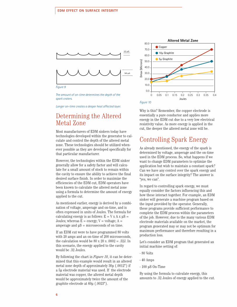
Determining the Altered Metal ZoneMost manufacturers of EDM sinkers today have technologies developed within the generator to cal-culate and control the depth of the altered metal zone. These technologies should be utilized when-ever possible as they are developed specifically for that particular manufacturer.
However, the technologies within the EDM sinker generally allow for a safety factor and will calcu-late for a small amount of stock to remain within the cavity to ensure the ability to achieve the final desired surface finish. In order to maximize the efficiencies of the EDM cut, EDM operators have been known to calculate the altered metal zone using a formula to determine the amount of energy applied to the cut.
As mentioned earlier, energy is derived by a combi-nation of voltage, amperage and on-time, and is often expressed in units of Joules. The formula for calculating energy is as follows: E = V x A x μS = Joules; whereas E = energy; V = voltage; A = amperage and μS = microseconds of on time.
If an EDM cut were to have programmed 80 volts with 20 amps and an on-time of 200 microseconds, the calculation would be 80 x 20 x .0002 = .32J. In this scenario, the energy applied to the cavity would be .32 Joules.
By following the chart in Figure 10, it can be deter-mined that this example would result in an altered metal zone depth of approximately 30μ (.0012") if a 5μ electrode material was used. If the electrode material was copper, the altered metal depth would be approximately twice the amount of the graphite electrode at 60μ (.0023").
Why is this? Remember, the copper electrode is essentially a pure conductor and applies more energy in the EDM cut due to a very low electrical resistivity value. As more energy is applied in the cut, the deeper the altered metal zone will be.
Controlling Spark EnergyAs already mentioned, the energy of the spark is determined by voltage, amperage and the on-time used in the EDM process. So, what happens if we want to change EDM parameters to optimize the application but wish to maintain a constant spark? Can we have any control over the spark energy and its impact on the surface integrity? The answer is “yes, we can”.
In regard to controlling spark energy, we must equally consider the factors influencing this and how these interact together. For example, an EDM sinker will generate a machine program based on the input provided by the operator. Generally, these programs provide sufficient performance to complete the EDM process within the parameters of the job. However; due to the many various EDM electrode materials available on the market, the program generated may or may not be optimum for maximum performance and therefore resulting in a production loss.
Let’s consider an EDM program that generated an initial machine setting of:
- 80 Volts
- 40 Amps
- 100 μS On-Time
By using the formula to calculate energy, this amounts to .32 Joules of energy applied to the cut.
Figure 9
The amount of on-time determines the depth of thespark craters.
Longer on-time creates a deeper heat affected layer.Figure 10
Add to “On-Time” section, page 5 or wherever it will fit.
Figure 9: On-time
• The amount of on-time determines the depth of the spark craters
• Longer on-time creates a deeper heat affected layer
50 μS
12 μS
80.0
70.0
60.0
50.0
40.0
30.0
20.0
10.0
0.00 0.05 0.1 0.15 0.2 0.25 0.3 0.35 0.4
Altered Metal Zone
Joules
Dmax
(Mic
rons
)
Copper
10µ Graphite
5µ Graphite

7
EDM EFFECT ON SURFACE INTEGRITY
Did you know there are several other machine parameters that can also apply this same amount of energy to the cut?
For example, Figure 11 illustrates different EDM parameters that will generate the same amount of energy in the EDM cut.
With this; provided the same electrode material was used, it is feasible that each of these parame-ters will provide the same EDM performance in regard to metal removal, overburn, recast and sur-face finish. However, these results could differ with electrode materials of varying electrical resistivity.
Using this information, machine parameters can be optimized specific to the type of electrode material being used. This allows for enhanced performance without the concerns of jeopardizing surface integ-rity.
Voltage (V) 80 80 80 60 60 60
Amperage (A) 20 40 80 27 54 108
On-Time (μS) 200 100 50 200 100 50
Formula V*A*μS = E
80*20*.0002
80*40*.0001
80*80*.00005
60*27*.0002
60*54*.0001
60*108*.00005
Total Energy (J) 0.32 0.32 0.32 0.32 0.32 0.32
Figure 11
ConclusionMaintaining the integrity of the cavity is essential to producing a quality mold. If the integrity were jeopardized, the life of the mold is significantly reduced—therefore increasing manufacturing costs.
With an understanding of the facets affecting the integrity of the cavity, the EDM’er will be able to optimize the EDM process while mitigating the probability of mold failure due to existing micro-cracks or flaws within the cavity. As the EDM pro-cess is optimized, the potential exists for increased throughput and reduced delivery times.

POCO GRAPITE, INC. Corporate Headquarters | 300 Old Greenwood Rd. | Decatur, Texas 76234 USATelephone: 1.940.627.2121 | Facsimile: 1.940.393.8366 | www.poco.com
©2010-2016 Poco Graphite, Inc. All rights reserved EDM-117919-0816
POCO® is a registered trademark of Poco Graphite, Inc.
EDM EFFECT ON SURFACE INTEGRITY
For More InformationPlease call your local distributor to learn what POCO can do for you. Visit www.poco.com and select the EDM Distributors for the location nearest you.
EDM Technical ManualThe POCO EDM Technical Manual is now available online at www.EDMTechMan.com or as an app for your iOS or Android device.
iOS Device Android Device