Embed Size (px)
Citation preview

Digital Temperature Controllers
User’s ManualE5CCE5EC
H174-E1-02
Appendices
Index
Preparations
Introduction
AdvancedOperations
BasicOperation
Part Names andBasic Procedures
User Calibration
Parameters
1
2
3
4
5
6
7
A
I


1
Preface
E5CC/E5EC Digital Temperature Controllers User’s Manual (H174)
Preface
The E5CC and E5EC are Digital Controllers. The main functions and characteristics of these DigitalControllers are as follows:
• Any of the following types of input can be used: thermocouple, platinum resistance thermometer,infrared sensor, analog voltage, or analog current.
• Either standard or heating/cooling control can be performed. • Both auto-tuning and self-tuning are supported.• Event inputs can be used to switch set points (multi-SP function), switch between RUN and STOP
status, switch between automatic and manual operation, start/reset the simple program function, andperform other operations.
• Heater burnout detection and heater short (HS) alarms functions are supported. (Applicable modelswith heater burnout detection function.)
• Communications are supported. (Applicable to models with communications.)• User calibration of the sensor input is supported.• User calibration of the transfer output is supported. (Applicable to models with a transfer output.)• The structure is waterproof (IP66).• Conforms to UL, CSA, and IEC safety standards and EMC Directive.
This manual describes how to use the E5CC/E5EC. Read this manual thoroughly and be sure youunderstand it before attempting to use the Digital Controller and use the Digital Controller correctlyaccording to the information provided. Keep this manual in a safe place for easy reference. Refer to thefollowing manual for further information on communications: E5CC/E5EC Digital Temperature Control-lers Communications Manual (Cat. No. H175).
© OMRON, 2011All rights reserved. No part of this publication may be reproduced, stored in a retrieval system or transmitted, in any form, or by any means, mechanical, electronic, photocopying, recording, or otherwise, without the prior written permission of OMRON.No patent liability is assumed with respect to the use of the information contained herein. Moreover, because OMRON is constantly striving to improve its high-quality products, the information contained in this manual is subject to change without notice. Every precaution has been taken in the preparation of this manual. Nevertheless, OMRON assumes no responsibility for errors or omissions. Neither is any liability assumed for damages resulting from the use of the information contained in this publication.

Read and Understand this Manual
2 E5CC/E5EC Digital Temperature Controllers User’s Manual (H174)
Read and Understand this Manual
Please read and understand this manual before using the products. Please consult your OMRON representative if you have any questions or comments.
Warranty and Limitations of Liability
WARRANTY
OMRON's exclusive warranty is that the products are free from defects in materials and workmanship for a period of one year (or other period if specified) from date of sale by OMRON.
OMRON MAKES NO WARRANTY OR REPRESENTATION, EXPRESS OR IMPLIED, REGARDING NON-INFRINGEMENT, MERCHANTABILITY, OR FITNESS FOR PARTICULAR PURPOSE OF THE PRODUCTS. ANY BUYER OR USER ACKNOWLEDGES THAT THE BUYER OR USER ALONE HAS DETERMINED THAT THE PRODUCTS WILL SUITABLY MEET THE REQUIREMENTS OF THEIR INTENDED USE. OMRON DISCLAIMS ALL OTHER WARRANTIES, EXPRESS OR IMPLIED.
LIMITATIONS OF LIABILITY
OMRON SHALL NOT BE RESPONSIBLE FOR SPECIAL, INDIRECT, OR CONSEQUENTIAL DAMAGES, LOSS OF PROFITS OR COMMERCIAL LOSS IN ANY WAY CONNECTED WITH THE PRODUCTS, WHETHER SUCH CLAIM IS BASED ON CONTRACT, WARRANTY, NEGLIGENCE, OR STRICT LIABILITY.
In no event shall the responsibility of OMRON for any act exceed the individual price of the product on which liability is asserted.
IN NO EVENT SHALL OMRON BE RESPONSIBLE FOR WARRANTY, REPAIR, OR OTHER CLAIMS REGARDING THE PRODUCTS UNLESS OMRON'S ANALYSIS CONFIRMS THAT THE PRODUCTS WERE PROPERLY HANDLED, STORED, INSTALLED, AND MAINTAINED AND NOT SUBJECT TO CONTAMINATION, ABUSE, MISUSE, OR INAPPROPRIATE MODIFICATION OR REPAIR.

3
Read and Understand this Manual
E5CC/E5EC Digital Temperature Controllers User’s Manual (H174)
Application Considerations
SUITABILITY FOR USE
OMRON shall not be responsible for conformity with any standards, codes, or regulations that apply to the combination of products in the customer's application or use of the products.
At the customer's request, OMRON will provide applicable third party certification documents identifying ratings and limitations of use that apply to the products. This information by itself is not sufficient for a complete determination of the suitability of the products in combination with the end product, machine, system, or other application or use.
The following are some examples of applications for which particular attention must be given. This is not intended to be an exhaustive list of all possible uses of the products, nor is it intended to imply that the uses listed may be suitable for the products:
• Outdoor use, uses involving potential chemical contamination or electrical interference, or conditions or uses not described in this manual.
• Nuclear energy control systems, combustion systems, railroad systems, aviation systems, medical equipment, amusement machines, vehicles, safety equipment, and installations subject to separate industry or government regulations.
• Systems, machines, and equipment that could present a risk to life or property.
Please know and observe all prohibitions of use applicable to the products.
NEVER USE THE PRODUCTS FOR AN APPLICATION INVOLVING SERIOUS RISK TO LIFE OR PROPERTY WITHOUT ENSURING THAT THE SYSTEM AS A WHOLE HAS BEEN DESIGNED TO ADDRESS THE RISKS, AND THAT THE OMRON PRODUCTS ARE PROPERLY RATED AND INSTALLED FOR THE INTENDED USE WITHIN THE OVERALL EQUIPMENT OR SYSTEM.
PROGRAMMABLE PRODUCTS
OMRON shall not be responsible for the user's programming of a programmable product, or any consequence thereof.
Read and Understand this Manual
4 E5CC/E5EC Digital Temperature Controllers User’s Manual (H174)
Disclaimers
CHANGE IN SPECIFICATIONS
Product specifications and accessories may be changed at any time based on improvements and other reasons.
It is our practice to change model numbers when published ratings or features are changed, or when significant construction changes are made. However, some specifications of the products may be changed without any notice. When in doubt, special model numbers may be assigned to fix or establish key specifications for your application on your request. Please consult with your OMRON representative at any time to confirm actual specifications of purchased products.
DIMENSIONS AND WEIGHTS
Dimensions and weights are nominal and are not to be used for manufacturing purposes, even when tolerances are shown.
PERFORMANCE DATA
Performance data given in this manual is provided as a guide for the user in determining suitability and does not constitute a warranty. It may represent the result of OMRON's test conditions, and the users must correlate it to actual application requirements. Actual performance is subject to the OMRON Warranty and Limitations of Liability.
ERRORS AND OMISSIONS
The information in this manual has been carefully checked and is believed to be accurate; however, no responsibility is assumed for clerical, typographical, or proofreading errors, or omissions.

5
Safety Precautions
E5CC/E5EC Digital Temperature Controllers User’s Manual (H174)
Safety Precautions
Definition of Precautionary InformationThe following notation is used in this manual to provide precautions required to ensure safe usage ofthe product.The safety precautions that are provided are extremely important to safety. Always read and heed theinformation provided in all safety precautions. The following notation is used.
CAUTIONIndicates a potentially hazardous situation which, if not avoided,may result in minor or moderate injury or in property damage.
Symbols
Symbol Meaning
Caution
• General Caution Indicates non-specific general cautions, warnings, and dangers.
• Electrical Shock CautionIndicates possibility of electric shock under specific conditions.
Prohibition
• General ProhibitionIndicates non-specific general prohibitions.
Mandatory Caution
• General CautionIndicates non-specific general cautions, warnings, and dangers.

Safety Precautions
6 E5CC/E5EC Digital Temperature Controllers User’s Manual (H174)
Safety Precautions
*1 A SELV circuit is one separated from the power supply with double insulation or reinforced insulation, thatdoes not exceed 30 V r.m.s. and 42.4 V peak or 60 VDC.
*2 A class 2 power supply is one tested and certified by UL as having the current and voltage of thesecondary output restricted to specific levels.
CAUTION
Minor injury due to electric shock may occasionally occur.Do not touch the terminals while power is being supplied.
Electric shock, fire, or malfunction may occasionally occur.Do not allow metal objects, conductors, cuttings from installationwork, or moisture to enter the Digital Controller or a Setup Tool port. Attach the cover to the front-panel Setup Tool port whenever you arenot using it to prevent foreign objects from entering the port.
Minor injury from explosion may occasionally occur.Do not use the product where subject to flammable or explosive gas.
Fire may occasionally occur. Do not allow dirt or other foreign objects to enter a Setup Tool port,or between the pins on the connectors on the Setup Tool cable.
Minor electric shock, fire, or malfunction may occasionally occur.Never disassemble, modify, or repair the product or touch any of theinternal parts.
CAUTION - Risk of Fire and Electric Shock(a) This product is UL recognized as Open Type Process Control
Equipment. It must be mounted in an enclosure that does notallow fire to escape externally.
(b) More than one disconnect switch may be required tode-energize the equipment before servicing.
(c) Signal inputs are SELV, limited energy. *1
(d) Caution: To reduce the risk of fire or electric shock, do not
interconnect the outputs of different Class 2 circuits.*2
If the output relays are used past their life expectancy, contact fusing or burning may occasionally occur.Always consider the application conditions and use the output relayswithin their rated load and electrical life expectancy. The lifeexpectancy of output relays varies considerably with the output loadand switching conditions.

7
Safety Precautions
E5CC/E5EC Digital Temperature Controllers User’s Manual (H174)
CAUTION
Loose screws may occasionally result in fire. Tighten the terminal screws to the specified torque of 0.43 to 0.58N·m.
Set the parameters of the product so that they are suitable for thesystem being controlled. If they are not suitable, unexpectedoperation may occasionally result in property damage or accidents.
A malfunction in the Digital Controller may occasionally make controloperations impossible or prevent alarm outputs, resulting in propertydamage. To maintain safety in the event of malfunction of the DigitalController, take appropriate safety measures, such as installing amonitoring device on a separate line.

Precautions for Safe Use
8 E5CC/E5EC Digital Temperature Controllers User’s Manual (H174)
Precautions for Safe Use
Be sure to observe the following precautions to prevent operation failure, malfunction, or adverseaffects on the performance and functions of the product. Not doing so may occasionally result in unex-pected events. Use the product within the specifications. • The product is designed for indoor use only. Do not use or store the product outdoors or in any of the
following locations.Locations directly subject to heat radiated from heating equipment.Locations subject to splashing liquid or oil atmosphere.Locations subject to direct sunlight.Locations subject to dust or corrosive gas (in particular, sulfide gas and ammonia gas).Locations subject to intense temperature change.Locations subject to icing and condensation.Locations subject to vibration and large shocks.
• Use and store the Digital Controller within the rated ambient temperature and humidity.Gang-mounting two or more Digital Controllers, or mounting Digital Controllers above each other maycause heat to build up inside the Digital Controllers, which will shorten their service life. In such acase, use forced cooling by fans or other means of air ventilation to cool down the Digital Controllers.
• To allow heat to escape, do not block the area around the product. Do not block the ventilation holeson the product.
• Be sure to wire properly with correct polarity of terminals.• Use the specified size of crimped terminals (M3, width of 5.8 mm or less) for wiring. To connect bare
wires to the terminal block, use copper braided or solid wires with a gage of AWG24 to AWG18
(equal to a cross-sectional area of 0.205 to 0.8231 mm2). (The stripping length is 6 to 8 mm.) Up totwo wires of the same size and type, or two crimped terminals can be inserted into a single terminal.
• Do not wire the terminals that are not used.• To avoid inductive noise, keep the wiring for the Digital Controller's terminal block away from power
cables that carry high voltages or large currents. Also, do not wire power lines together with orparallel to Digital Controller wiring. Using shielded cables and using separate conduits or ducts isrecommended.Attach a surge suppressor or noise filter to peripheral devices that generate noise (in particular,motors, transformers, solenoids, magnetic coils or other equipment that have an inductancecomponent).When a noise filter is used at the power supply, first check the voltage or current, and attach the noisefilter as close as possible to the Digital Controller.Allow as much space as possible between the Digital Controller and devices that generate powerfulhigh frequencies (high-frequency welders, high-frequency sewing machines, etc.) or surge.
• Use this product within the rated load and power supply.• Make sure that the rated voltage is attained within 2 seconds of turning ON the power using a switch
or relay contact. If the voltage is applied gradually, the power may not be reset or output malfunctionsmay occur.
• Make sure that the Digital Controller has 30 minutes or more to warm up after turning ON the powerbefore starting actual control operations to ensure the correct temperature display.
• When executing self-tuning, turn ON power for the load (e.g., heater) at the same time as or beforesupplying power to the Digital Controller. If power is turned ON for the Digital Controller before turningON power for the load, self-tuning will not be performed properly and optimum control will not beachieved.

9
Precautions for Safe Use
E5CC/E5EC Digital Temperature Controllers User’s Manual (H174)
• A switch or circuit breaker should be provided close to Digital Controller. The switch or circuit breakershould be within easy reach of the operator, and must be marked as a disconnecting means forDigital Controller.
• Wipe off any dirt from the Digital Controller with a soft dry cloth. Never use thinners, benzine, alcohol,or any cleaners that contain these or other organic solvents. Deformation or discoloration may occur.
• Design the system (e.g., control panel) considering the 2 seconds of delay in setting the DigitalController’s output after the power supply is turned ON.
• The output will turn OFF when you move to the Initial Setting Level. Take this into consideration whenperforming control.
• The number of non-volatile memory write operations is limited. Therefore, use RAM write mode whenfrequently overwriting data during communications or other operations.
• Use suitable tools when taking the Digital Controller apart for disposal. Sharp parts inside the DigitalController may cause injury.
• Do not connect cables to both the front-panel Setup Tool port and the top-panel Setup Tool port at thesame time. The Digital Controller may be damaged or may malfunction.
• Do not exceed the communications distance that is given in the specifications. Use the specifiedcommunications cable.
• Do not turn the power supply to the Digital Controller ON or OFF while the USB-Serial ConversionCable is connected. The Digital Controller may malfunction.
Installation Precautions
10 E5CC/E5EC Digital Temperature Controllers User’s Manual (H174)
Installation Precautions
Service LifeUse the Digital Controller within the following temperature and humidity ranges:Temperature: −10 to 55°C (with no icing or condensation), Humidity: 25% to 85%If the Digital Controller is installed inside a control board, the ambient temperature must be kept tounder 55°C, including the temperature around the Controller. The service life of electronic devices like Digital Controllers is determined not only by the number oftimes the relay is switched but also by the service life of internal electronic components. Componentservice life is affected by the ambient temperature: the higher the temperature, the shorter theservice life and, the lower the temperature, the longer the service life. Therefore, the service life canbe extended by lowering the temperature of the Digital Controller. When two or more Digital Controllers are mounted horizontally close to each other or vertically nextto one another, the internal temperature will increase due to heat radiated by the Digital Controllersand the service life will decrease. In such a case, use forced cooling by fans or other means of airventilation to cool down the Digital Controllers. When providing forced cooling, however, be carefulnot to cool down the terminals sections alone to avoid measurement errors.
Ambient NoiseTo avoid inductive noise, keep the wiring for the Digital Controller's terminal block wiring away frompower cables carrying high voltages or large currents. Also, do not wire power lines together with orparallel to Digital Controller wiring. Using shielded cables and using separate conduits or ducts isrecommended.Attach a surge suppressor or noise filter to peripheral devices that generate noise (in particular,motors, transformers, solenoids, magnetic coils or other equipment that have an inductance compo-nent). When a noise filter is used at the power supply, first check the voltage or current, and attachthe noise filter as close as possible to the Digital Controller.Allow as much space as possible between the Digital Controller and devices that generate powerfulhigh frequencies (high-frequency welders, high-frequency sewing machines, etc.) or surge.
Ensuring Measurement AccuracyWhen extending or connecting the thermocouple lead wire, be sure to use compensating wires thatmatch the thermocouple types. When extending or connecting the lead wire of the platinum resistance thermometer, be sure to usewires that have low resistance and keep the resistance of the three lead wires the same. Mount the Digital Controller so that it is horizontally level. If the measurement accuracy is low, check to see if input shift has been set correctly.

11
Installation Precautions
E5CC/E5EC Digital Temperature Controllers User’s Manual (H174)
WaterproofingThe degree of protection is as shown below. Sections without any specification on their degree ofprotection or those with IP@0 are not waterproof.Front panel: IP66Rear case: IP20, Terminal section: IP00When waterproofing is required, insert the Waterproof Packing on the backside of the front panel.Keep the Port Cover on the front-panel Setup Tool port of the E5EC securely closed. The degree ofprotection when the Waterproof Packing is used is IP66. To maintain an IP66 degree of protection,the Waterproof Packing and the Port Cover for the front-panel Setup Tool port must be periodicallyreplaced because they may deteriorate, shrink, or harden depending on the operating environment.The replacement period will vary with the operating environment. Check the required period in theactual application. Use 3 years or sooner as a guideline. If the Waterproof Packing and Port Coverare not periodically replaced, waterproof performance may not be maintained. If a waterproofstructure is not required, then the Waterproof Packing does not need to be installed.

Precautions for Operation
12 E5CC/E5EC Digital Temperature Controllers User’s Manual (H174)
Precautions for Operation
• It takes approximately two seconds for the outputs to turn ON from after the power supply is turnedON. Due consideration must be given to this time when incorporating Digital Controllers into a controlpanel or similar device.
• Make sure that the Digital Controller has 30 minutes or more to warm up after turning ON the powerbefore starting actual control operations to ensure the correct temperature display.
• When using self-tuning, turn ON power for the load (e.g., heater) at the same time as or beforesupplying power to the Digital Controller. If power is turned ON for the Digital Controller before turningON power for the load, self-tuning will not be performed properly and optimum control will not beachieved. When starting operation after the Digital Controller has warmed up, turn OFF the powerand then turn it ON again at the same time as turning ON power for the load. (Instead of turning theDigital Controller OFF and ON again, switching from STOP Mode to RUN Mode can also be used.)
• Avoid using the Digital Controller in places near a radio, television set, or wireless installing. TheDigital Controller may cause radio disturbance for these devices.

13
Preparations for Use
E5CC/E5EC Digital Temperature Controllers User’s Manual (H174)
Preparations for Use
Be sure to thoroughly read and understand the manual provided with the product, and check the follow-ing points.
Timing Check point DetailsPurchasing the product
Product appearance
After purchase, check that the product and packaging are not dented or otherwise damaged. Damaged internal parts may prevent optimum control.
Product model and specifications
Make sure that the purchased product meets the required specifications.
Setting the Unit
Product installation location
Provide sufficient space around the product for heat dissipation. Do not block the vents on the product.
Wiring Terminal wiring Do not subject the terminal screws to excessive stress (force) when tightening them.Make sure that there are no loose screws after tightening terminal screws to the specified torque of 0.43 to 0.58 N·m.
Be sure to confirm the polarity for each terminal before wiring the terminal block and connectors.
Power supply inputs
Wire the power supply inputs correctly. Incorrect wiring will result in damage to the internal circuits.
Operating environment
Ambient temperature
The ambient operating temperature for the product is −10 to 55°C (with no condensation or icing). To extend the service life of the product, install it in a location with an ambient temperature as low as possible. In locations exposed to high temperatures, if necessary, cool the products using a fan or other cooling method.
Vibration and shock
Check whether the standards related to shock and vibration are satisfied at the installation environment. (Install the product in locations where the contactors will not be subject to vibration or shock.)
Foreign particles Install the product in a location that is not subject to liquid or foreign particles entering the product.

Revision History
14 E5CC/E5EC Digital Temperature Controllers User’s Manual (H174)
Revision History
A manual revision code appears as a suffix to the catalog number on the front cover of the manual.
Revision code Date Revised content01 December 2011 Original production
02 January 2012 Page 9: Made correction in Precautions for Safe Use.
H174-E1-02Revision code
Cat. No.

15
Conventions Used in This Manual
E5CC/E5EC Digital Temperature Controllers User’s Manual (H174)
Conventions Used in This Manual
The E5CC-@@ and E5EC-@@ are given as the E5CC and E5EC when all of the models share function-ality.The following notation is used when specifying differences in functionality
The following abbreviations are used in parameter names, figures, and other descriptions. Theseabbreviations mean the following:
* “EU” stands for Engineering Unit. EU is used as the minimum unit for engineering units such as °C, m, and g.The size of the EU depends on the input type. For example, when the input temperature setting range is −200to 1,300°C, 1 EU is 1°C, and when the input temperature setting range is −20.0 to 500.0°C, 1 EU is 0.1°C.For analog inputs, the size of the EU depends on the decimal point position of the scaling setting, and 1 EU isthe minimum scaling unit.
Model Notation
Event inputs CommunicationsRemote SP
InputHB alarm and HS
alarmTransfer output
E5CC/E5EC-@-000 --- --- --- --- --- E5CC-@-001 2 --- --- 1 ---
E5CC-@-002 --- RS-485 --- 1 ---
E5CC-@-003 --- RS-485 --- 2 (for 3-phase heaters)
---
E5CC/E5EC-@-004 2 RS-485 --- --- ---
E5CC/E5EC-@-005 4 --- --- --- ---
E5CC-@-006 2 --- --- --- Provided. E5CC-@-007 2 --- Provided. --- ---
E5EC-@-008 2 RS-485 --- 1 ---
E5EC-@-009 2 RS-485 --- 2 (for 3-phase heaters)
---
E5EC-@-010 4 --- --- 1 --- E5EC-@-011 6 --- Provided. 1 Provided.
E5EC-@-012 4 RS-485 Provided. 1 Provided.
E5EC-@-013 6 --- Provided. --- Provided. E5EC-@-014 4 RS-485 Provided. --- Provided.
Meanings of Abbreviations
Symbol TermPV Process value
SP Set pointSV Set value
AT Auto-tuning
ST Self-tuningEU Engineering unit*
LBA Loop burnout alarm
HB Heater burnoutHS Heater short
RSP Remote SP
LSP Local SP

Conventions Used in This Manual
16 E5CC/E5EC Digital Temperature Controllers User’s Manual (H174)
The following tables show the correspondence between the symbols displayed on the displays andalphabet characters.
How to Read Display Symbols
a b c d e f g h i j k l m
A B C D E F G H I J K L M
n o p q r s t u V w x y z
N O P Q R S T U V W X Y Z
How This Manual is Organized
Goal Related sections ContentsLearning about the appearance, features, functions, and model numbers of the E5CC/E5EC
Section 1 Introduction This section shows the appearance and describes the features, functions, and model numbers of the E5CC/E5EC.
Setting up the E5CC/E5EC Section 2 Preparations This section describes the steps that are required before turning ON the power supply to the E5CC/E5EC (including installation, terminal usage, wiring, and isolation/insulation block diagram). It also describes how to use the Setup Tool ports.
Learning the basic procedures from turning ON the power supply to the E5CC/E5EC to starting actual operation
Section 3 Part Names and Basic Procedures
This section describes the basic procedures from turning ON the power supply to the E5CC/E5EC to starting actual operation. It also gives the names of the parts of the E5CC/E5EC. This section serves as a basic tutorial for first-time users of the E5CC/E5EC.
Learning the basic operating methods for the E5CC/E5EC
Section 4 Basic OperationSection 6 Parameters
These sections describe the basic operating methods and provide specific examples of the following basic functions of the E5CC/E5EC.• Moving between setting levels• Setting the input type• Selecting the temperature unit• Selecting between PID control and ON/OFF
control• Setting the set point• Using ON/OFF control• Determining PID constants• Setting alarm outputs• Setting alarm hysteresis• Using heater burnout (HB) and heater short
(HS) alarms• Customizing the displays

17
Conventions Used in This Manual
E5CC/E5EC Digital Temperature Controllers User’s Manual (H174)
The following manual is also related to the E5CC/E5EC.
Learning advanced operating methods for the E5CC/E5EC
Section 5 Advanced OperationsSection 6 Parameters
These sections describe the following advanced operating methods to help you make the most of the E5CC/E5EC.• Input shift• Scaling upper/lower limits for an analog input• Heating and cooling control• Event inputs• Multi-SP• Upper/lower limits for the set point• SP ramp• Protection• Displaying changed parameters• OR output of alarms• Alarm delays and loop burnout alarms• Manual control• Transfer output• Simple programming• Output limits, MV at stop, and MV at PV error• Extraction of square root• MV rate of change• Setting the Shift Key (PF Key)• PV/SV status display• Communications with a host device (e.g., a
PLC)• Remote SP• Logic operations
Calibrating the E5CC/E5EC Section 7 User Calibration This section describes the procedures that you can use to calibrate the sensor or transfer output of the E5CC/E5EC.
Learning the specifications and parameters of the E5CC/E5EC
Appendices The appendices list the specifications and parameters of the E5CC/E5EC.
Related Manuals
Manual name Cat. No. ContentsE5CC/E5EC Digital Temperature Controllers Communications Manual
H175 This manual describes the command text and communications procedures to use the CompoWay/F and Modbus-RTU protocols for serial communications between the E5CC/E5EC and a host device (e.g., a PLC).
Goal Related sections Contents

Conventions Used in This Manual
18 E5CC/E5EC Digital Temperature Controllers User’s Manual (H174)

19
Sections in this Manual
E5CC/E5EC Digital Temperature Controllers User’s Manual (H174)
1
2
3
4
5
6
7
1
2
3
4
5
6
7
Introduction
Preparations
Part Names and Basic Procedures
Basic Operation
Advanced Operations
Parameters
User Calibration
A
A
Appendices
I
I
Index
Sections in this Manual

20 E5CC/E5EC Digital Temperature Controllers User’s Manual (H174)
CONTENTS
Preface .......................................................................................................................1
Read and Understand this Manual ..........................................................................2
Safety Precautions....................................................................................................5Definition of Precautionary Information ...................................................................................................... 1-5Symbols .................................................................................................................................................... 1-5
Precautions for Safe Use..........................................................................................8
Installation Precautions..........................................................................................10
Precautions for Operation ......................................................................................12
Preparations for Use ...............................................................................................13
Revision History ......................................................................................................14
Conventions Used in This Manual .........................................................................15Model Notation ......................................................................................................................................... 1-15Meanings of Abbreviations ....................................................................................................................... 1-15How to Read Display Symbols ................................................................................................................. 1-16How This Manual is Organized ................................................................................................................ 1-16Related Manuals ...................................................................................................................................... 1-17
Sections in this Manual ..........................................................................................19
Section 1 Introduction
1-1 Appearance, Features, and Functions of the E5CC/E5EC................................................... 1-21-1-1 Appearance................................................................................................................................. 1-21-1-2 Features ...................................................................................................................................... 1-21-1-3 Main Functions............................................................................................................................ 1-3
1-2 I/O Configuration and Model Number Legend ...................................................................... 1-51-2-1 I/O Configuration ......................................................................................................................... 1-51-2-2 Model Number Legends.............................................................................................................. 1-6
Section 2 Preparations
2-1 Installation................................................................................................................................ 2-22-1-1 Dimensions (Unit: mm)................................................................................................................ 2-22-1-2 Panel Cutout (Unit: mm).............................................................................................................. 2-32-1-3 Mounting ..................................................................................................................................... 2-5
2-2 Using the Terminals................................................................................................................. 2-72-2-1 E5CC Terminal Block Wiring Example........................................................................................ 2-72-2-2 E5EC Terminal Block Wiring Example ...................................................................................... 2-112-2-3 Precautions when Wiring .......................................................................................................... 2-162-2-4 Wiring........................................................................................................................................ 2-16
2-3 Insulation Block Diagrams.................................................................................................... 2-22
2-4 Using the Setup Tool Port..................................................................................................... 2-232-4-1 Procedure.................................................................................................................................. 2-232-4-2 Connection Method................................................................................................................... 2-232-4-3 Installing the Driver ................................................................................................................... 2-26

21E5CC/E5EC Digital Temperature Controllers User’s Manual (H174)
Section 3 Part Names and Basic Procedures
3-1 Basic Application Flow ........................................................................................................... 3-2
3-2 Power ON.................................................................................................................................. 3-3
3-3 Part Names, Part Functions, and Setting Levels .................................................................. 3-43-3-1 Part Names and Functions ......................................................................................................... 3-43-3-2 Entering Numeric Values ............................................................................................................ 3-73-3-3 Setting Levels ............................................................................................................................. 3-83-3-4 E5CC/E5EC Setting Levels ........................................................................................................ 3-9
3-4 Procedures after Turning ON the Power Supply................................................................. 3-133-4-1 Basic Flow of Operations.......................................................................................................... 3-133-4-2 Basic Procedure ....................................................................................................................... 3-13
Section 4 Basic Operation
4-1 Moving between Setting Levels ............................................................................................. 4-34-1-1 Moving to the Initial Setting Level ............................................................................................... 4-34-1-2 Moving to the Adjustment Level.................................................................................................. 4-44-1-3 Moving to the Protect Level ........................................................................................................ 4-44-1-4 Moving to the Advanced Function Setting Level ......................................................................... 4-54-1-5 Moving to the Communications Setting Level............................................................................. 4-7
4-2 Initial Setting Examples .......................................................................................................... 4-8
4-3 Setting the Input Type ........................................................................................................... 4-104-3-1 Input Type ................................................................................................................................. 4-10
4-4 Selecting the Temperature Unit............................................................................................ 4-124-4-1 Temperature Unit ...................................................................................................................... 4-12
4-5 Selecting PID Control or ON/OFF Control ........................................................................... 4-13
4-6 Setting Output Specifications .............................................................................................. 4-144-6-1 Control Periods ......................................................................................................................... 4-144-6-2 Direct and Reverse Operation .................................................................................................. 4-144-6-3 Assigned Output Functions....................................................................................................... 4-154-6-4 Auxiliary Output Opening or Closing in Alarm .......................................................................... 4-18
4-7 Setting the Set Point (SP) ..................................................................................................... 4-194-7-1 Changing the SP....................................................................................................................... 4-19
4-8 Using ON/OFF Control .......................................................................................................... 4-204-8-1 ON/OFF Control........................................................................................................................ 4-204-8-2 Settings..................................................................................................................................... 4-21
4-9 Determining PID Constants(AT, ST, Manual Setup)4-234-9-1 AT (Auto-tuning)........................................................................................................................ 4-234-9-2 ST (Self-tuning)......................................................................................................................... 4-254-9-3 Manual Setup............................................................................................................................ 4-28
4-10 Alarm Outputs........................................................................................................................ 4-304-10-1 Alarm Types.............................................................................................................................. 4-304-10-2 Alarm Values ............................................................................................................................ 4-34
4-11 Alarm Hysteresis ................................................................................................................... 4-374-11-1 Standby Sequence ................................................................................................................... 4-374-11-2 Alarm Latch .............................................................................................................................. 4-38
4-12 Using Heater Burnout (HB) and Heater Short (HS) Alarms ............................................... 4-394-12-1 HB Alarm .................................................................................................................................. 4-394-12-2 HS Alarm .................................................................................................................................. 4-414-12-3 Installing Current Transformers (CT) ........................................................................................ 4-434-12-4 Calculating Detection Current Values ....................................................................................... 4-454-12-5 Application Examples ............................................................................................................... 4-45
4-13 Customizing the PV/SP Display ........................................................................................... 4-494-13-1 PV/SP Display Selections......................................................................................................... 4-49

22 E5CC/E5EC Digital Temperature Controllers User’s Manual (H174)
Section 5 Advanced Operations
5-1 Shifting Input Values ............................................................................................................... 5-3
5-2 Setting Scaling Upper and Lower Limits for Analog Inputs ................................................ 5-5
5-3 Executing Heating/Cooling Control ....................................................................................... 5-75-3-1 Heating/Cooling Control .............................................................................................................. 5-7
5-4 Using Event Inputs ................................................................................................................ 5-115-4-1 Event Input Settings .................................................................................................................. 5-115-4-2 How to Use the Multi-SP Function ............................................................................................ 5-115-4-3 Operation Commands Other than Multi-SP .............................................................................. 5-12
5-5 Setting the SP Upper and Lower Limit Values .................................................................... 5-155-5-1 Set Point Limiter ........................................................................................................................ 5-155-5-2 Setting....................................................................................................................................... 5-16
5-6 Using the SP Ramp Function to Limit the SP Change Rate .............................................. 5-175-6-1 SP Ramp................................................................................................................................... 5-17
5-7 Using the Key Protect Level ................................................................................................. 5-195-7-1 Protection .................................................................................................................................. 5-195-7-2 Entering the Password to Move to the Protect Level................................................................. 5-20
5-8 Displaying Only Parameters That Have Been Changed..................................................... 5-225-8-1 Displaying Changed Parameters............................................................................................... 5-22
5-9 OR Output of Alarms............................................................................................................. 5-245-9-1 Integrated Alarm ....................................................................................................................... 5-24
5-10 Alarm Delays .......................................................................................................................... 5-265-10-1 Alarm Delays............................................................................................................................. 5-26
5-11 Loop Burnout Alarm.............................................................................................................. 5-285-11-1 Loop Burnout Alarm (LBA)........................................................................................................ 5-28
5-12 Performing Manual Control................................................................................................... 5-315-12-1 Manual Operation...................................................................................................................... 5-31
5-13 Using the Transfer Output .................................................................................................... 5-345-13-1 Transfer Output Function........................................................................................................... 5-34
5-14 Using the Simple Program Function.................................................................................... 5-375-14-1 Simple Program Function.......................................................................................................... 5-375-14-2 Operation at the Program End .................................................................................................. 5-395-14-3 Application Example Using a Simple Program.......................................................................... 5-41
5-15 Output Adjustment Functions.............................................................................................. 5-425-15-1 Output Limits ............................................................................................................................. 5-425-15-2 MV at Stop ................................................................................................................................ 5-425-15-3 MV at PV Error .......................................................................................................................... 5-43
5-16 Using the Extraction of Square Root Parameter ................................................................ 5-445-16-1 Extraction of Square Roots ....................................................................................................... 5-44
5-17 Setting the Width of MV Variation ........................................................................................ 5-465-17-1 MV Change Rate Limit .............................................................................................................. 5-46
5-18 Setting the PF Key ................................................................................................................. 5-485-18-1 PF Setting (Function Key) ........................................................................................................ 5-48
5-19 Displaying PV/SV Status ....................................................................................................... 5-515-19-1 PV and SV Status Display Functions ........................................................................................ 5-51
5-20 Communications with a Host Device (e.g., a PLC) ............................................................. 5-53
5-21 Using a Remote SP................................................................................................................ 5-55
5-22 Logic Operations ................................................................................................................... 5-575-22-1 The Logic Operation Function (CX-Thermo)............................................................................. 5-575-22-2 Using Logic Operations............................................................................................................. 5-57

23E5CC/E5EC Digital Temperature Controllers User’s Manual (H174)
Section 6 Parameters
6-1 Conventions Used in this Section.......................................................................................... 6-2
6-2 Protect Level ............................................................................................................................ 6-3
6-3 Operation Level ....................................................................................................................... 6-7
6-4 Adjustment Level................................................................................................................... 6-17
6-5 Monitor/Setting Item Level.................................................................................................... 6-35
6-6 Manual Control Level ............................................................................................................ 6-36
6-7 Initial Setting Level ................................................................................................................ 6-38
6-8 Advanced Function Setting Level ........................................................................................ 6-54
6-9 Communications Setting Level ............................................................................................ 6-84
Section 7 User Calibration
7-1 User Calibration....................................................................................................................... 7-2
7-2 Parameter Structure ................................................................................................................ 7-3
7-3 Thermocouple Calibration ...................................................................................................... 7-4
7-4 Resistance Thermometer Calibration.................................................................................... 7-7
7-5 Calibrating Analog Input ........................................................................................................ 7-9
7-6 Calibrating the Transfer Output............................................................................................ 7-11
7-7 Checking Indication Accuracy ............................................................................................. 7-13
Section A Appendices
A-1 Specifications ..........................................................................................................................A-2A-1-1 Ratings........................................................................................................................................A-2A-1-2 Characteristics ............................................................................................................................A-4A-1-3 Rating and Characteristics of Options ........................................................................................A-5A-1-4 Waterproof Packing ....................................................................................................................A-5A-1-5 Setup Tool Port Cover for Front Panel ........................................................................................A-6
A-2 Current Transformer (CT)........................................................................................................A-7A-2-1 Specifications..............................................................................................................................A-7A-2-2 Dimensions (Unit: mm) ...............................................................................................................A-7
A-3 USB-Serial Conversion Cable and Conversion Cable ..........................................................A-8A-3-1 E58-CIFQ2 USB-Serial Conversion Cable .................................................................................A-8A-3-2 E58-CIFQ2-E Conversion Cable.................................................................................................A-9
A-4 Error Displays ........................................................................................................................A-10
A-5 Troubleshooting.....................................................................................................................A-13
A-6 Parameter Operation Lists....................................................................................................A-16A-6-1 Operation Level.........................................................................................................................A-16A-6-2 Adjustment Level ......................................................................................................................A-17A-6-3 Initial Setting Level.................................................................................................................... A-18A-6-4 Manual Control Level ................................................................................................................A-21A-6-5 Monitor/Setting Item Level ........................................................................................................A-21A-6-6 Advanced Function Setting Level .............................................................................................A-22A-6-7 Protect Level .............................................................................................................................A-26A-6-8 Communications Setting Level .................................................................................................A-26A-6-9 Initialization According to Parameter Changes.........................................................................A-27

24 E5CC/E5EC Digital Temperature Controllers User’s Manual (H174)
A-7 Sensor Input Setting Range, Indication Range, Control Range........................................A-30
A-8 Setting Levels Diagram.........................................................................................................A-31
A-9 Parameter Flow ......................................................................................................................A-32
Index

1 - 1E5CC/E5EC Digital Temperature Controllers User’s Manual (H174)
1
1-1 Appearance, Features, and Functions of the E5CC/E5EC . . . . . . . . . . . . . 1-21-1-1 Appearance . . . . . . . . . . . . . . . . . . . . . . . . . . . . . . . . . . . . . . . . . . . . . . . . . . . . 1-21-1-2 Features . . . . . . . . . . . . . . . . . . . . . . . . . . . . . . . . . . . . . . . . . . . . . . . . . . . . . . 1-21-1-3 Main Functions . . . . . . . . . . . . . . . . . . . . . . . . . . . . . . . . . . . . . . . . . . . . . . . . . 1-3
1-2 I/O Configuration and Model Number Legend . . . . . . . . . . . . . . . . . . . . . . . 1-51-2-1 I/O Configuration . . . . . . . . . . . . . . . . . . . . . . . . . . . . . . . . . . . . . . . . . . . . . . . . 1-51-2-2 Model Number Legends . . . . . . . . . . . . . . . . . . . . . . . . . . . . . . . . . . . . . . . . . . 1-6
Introduction

1 Introduction
1 - 2 E5CC/E5EC Digital Temperature Controllers User’s Manual (H174)
1-1 Appearance, Features, and Functions of the E5CC/E5EC
This section compares the features of the E5CC/E5EC with the previous E5CN/E5EN Controllers.
Input sampling cycle: 50 msControl period: 0.1 s and 0.2 s have been added.Integral/differential time unit: Setting in increments of 0.1 s has been added.
• Number of event inputs: Increased from 2 to 4 for the E5CC and from 4 to 6 for the E5EC.• Number of auxiliary outputs: Increased from 2 to 3 for the E5CC and from 3 to 4 for the E5EC.• Remote SP inputs: A remote SP input that treats the external analog signal at the set point
(SP) has been added.
Universal input: The input sensor can be selected freely from the following for any model of the E5CCor E5EC: Thermocouple, resistance thermometer, ES1B Infrared Temperature Sen-sor, current, and voltage.
Digit shift: When setting the SP or other parameters, you can use a Shift Key (assigned to the PF Key)to shift the digit that is being set to aid changing the set values.
1-1-1 Appearance
• A stylish design that gives a new look to control panels.
• Large display characters and white backlight for better visibility.
• A compact size to help downsize control panels.• Much faster sampling and greater expandability than expected
in this class of Controller.
• Even easier to use than previous models.
1-1-2 Features
High-speed Control Capability
I/O Expandability
Universal Input Capability
Easier Numeric Inputs with a Digit Shift Key
E5CC E5EC

1 - 3
1 Introduction
E5CC/E5EC Digital Temperature Controllers User’s Manual (H174)
1-1 Ap
pearan
ce, Featu
res, and
Fu
nctio
ns o
f the E
5CC
/E5E
C
1
1-1-3 Main F
unctions
This port allows you to change or set parameters from the Setup Tool even when the Controller isinstalled in a panel.
This section introduces the main E5CC/E5EC functions. For details on particular functions and how touse them, refer to Section 3 Part Names and Basic Procedures and following sections.
Input Sensor TypesYou can connect the following sensors and signals to the universal input.
Control Outputs• A control output can be a relay, voltage (for driving SSR), or current output, depending on the
model.
Adjusting PID Constants• You can easily set the optimum PID constants by performing AT (auto-tuning) with the limit cycle
method or by performing ST (self-tuning) with the step response method.• You can also add RT(robust tuning) to give priority to control stability.
AlarmsStandard Alarms• You can output an alarm when the deviation, process value, set point, or manipulated value
reaches a specified value.• You can also output alarms for the PV rate of change and for loop burnouts.• If necessary, a more comprehensive alarm function can be achieved by setting a standby
sequence, alarm hysteresis, auxiliary output close in alarm/open in alarm, alarm latch, alarm ONdelay, and alarm OFF delay.
HB and HS Alarms• With models with the optional HB and HS alarms, you can detect heater burnout and heater short
alarms based on CT inputs.
Integrated Alarm• You can output an integrated alarm if a standard alarm, HB alarm, or HS alarm turns ON.
Event Inputs• With any E5CC/E5EC model that supports event inputs, you can use external contact or
non-contact inputs to achieve any of the following functions: Switching set points (Multi-SP No.Switch, 8 points max.), switching RUN/STOP, switching between automatic and manual operation,starting/resetting the program, inverting direct/reverse operation, switching the SP mode100% ATexecute/cancel, 40% AT execute/cancel, setting change enable/disable, communications writeenable/disable, and canceling the alarm latch.
Setup Tool Port on Front Panel of the E5EC
1-1-3 Main Functions
Thermocouple: K, J, T, E, L, U, N, R, S, B, W, PLII
Resistance thermometer: Pt100, JPt100
Infrared temperature sensor: ES1B10 to 70°C, 60 to 120°C, 115 to 165°C, 140 to 260°C
Current input: 4 to 20 mA DC, 0 to 20 mA DC
Voltage input: 1 to 5 VDC, 0 to 5 V DC, 0 to 10 V DC

1 Introduction
1 - 4 E5CC/E5EC Digital Temperature Controllers User’s Manual (H174)
Communications FunctionsWith any E5CC/E5EC model that supports communications, you can use communications via
CompoWay/F*1 or Modbus*2.
*1 CompoWay/F is an integrated general-purpose serial communications protocol developed by OMRON. It uses commands compliant with the well-established FINS, together with a consistent frame format on OMRON Programmable Controllers to facilitate communications between personal computers and components.
*2 Modbus is a communications control method conforming to the RTU Mode of Modbus Protocol.Modbus is a registered trademark of Schneider Electric.
Transfer OutputWith any E5CC/E5EC model that supports a transfer output, you can output the set point, processvalue, manipulated variable, or other values as a 4 to 20-mA or 1 to 5-V transfer output.
Remote SPWith any E5CC/E5EC model that supports remote SP input, you can set the set point with an analoginput.
RS-485 Interface
1 - 5
1 Introduction
E5CC/E5EC Digital Temperature Controllers User’s Manual (H174)
1-2 I/O C
on
figu
ration
and
Mo
del
Nu
mb
er Leg
end
1
1-2-1 I/O C
onfiguration
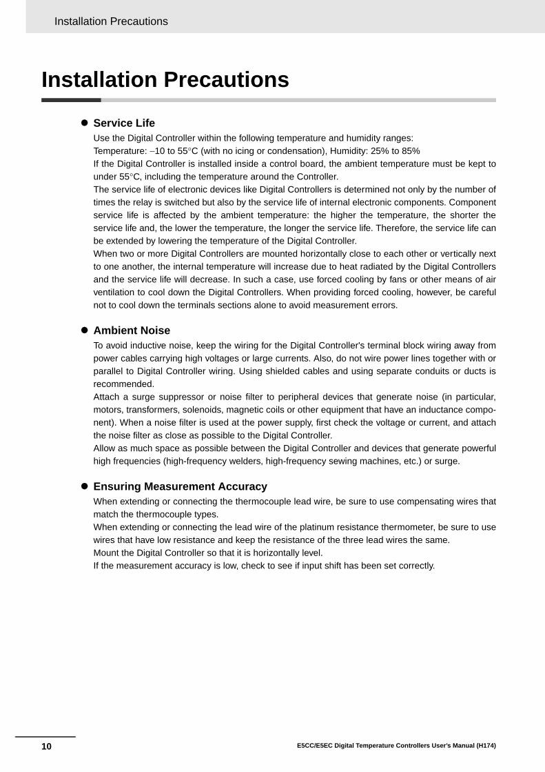
1-2 I/O Configuration and Model Number Legend
Note: Not all models support these functions. For details, refer to 1-2-2 Model Number Legends.
1-2-1 I/O Configuration
E5CC/E5EC
Auxiliary outputs 1 to 4
• Input type • Input shift
• Input filter • Moving average
• Extraction of square root • Analog scaling
Input signals
Event inputs (EV1 to EV6) • External inputs(contact or non-contact input)
Setting and monitoring
• Direct/reverse • Auto/manual
• Linear current • Voltage output(for driving SSR) • Relay
Outputs
• RS-485
PV
• Standard alarms (alarms 1 to 4) • HB alarm • HS alarm • Input error (S.ERR) • RSP input error
• Integrated alarm
• RUN status
• Program end
• Work bits 1 to 8
Manipulated value (MV)
Setup Tool (CX-Thermo)
Limits
Output signals
A: 100 to 240 VACorD: 24 VAC/DC
• CompoWay/F • Modbus-RTUCommunications
• Linear current • Linear voltage
Transfer output
CT input
Multi-SP
Input voltage from CT
Inputs
Set point (SP) Local SP
Analog input (current/voltage)
Control
• HB alarm • HS alarm
Alarms
Power supply
• Set point • Set point during SP ramp • Process value • Manipulated value
• Relay
Analog status
Control output 1
Contact status
Operation
Process value (PV) input • Thermocouple • Resistance thermometer • Infrared Temperature Sensor • Analog input (current/voltage)
• Linear current • Voltage output(for driving SSR) • Relay
Control output 2
• PID or • ON/OFF control
Heating/cooling
*
*
*
Remote SPSP mode
SP
• RUN/STOP switching • Auto/manual selection
• Program start
• 100% AT execute/cancel • 40% AT execute/cancel
• Alarm latch cancel • Multi-SP No.
• SP ramp
• Set point limiter
• Invert direct/reverse operation • SP mode (remote/local
switching)
• Setting change enable/disable
• Communications write enable/disable
• Standard control or • Heating/cooling
control
Automatic setting of PID constants with AT or ST
• MV limit • MV
rate-of-change limit
*Functions can be assigned individually for each output by changing the set values for the Control Output 1 and 2 Assignments and the Auxiliary Output 1 to 4 Assignments in the parameters in the advanced function setting level.

1 Introduction
1 - 6 E5CC/E5EC Digital Temperature Controllers User’s Manual (H174)
E5CC
*1 Options with HB and HS alarms (001 and 003) cannot be selected if a current output is selected for the control output.The control output cannot be used as a transfer output.
*2 If no auxiliary outputs (none) is selected, 000 (none) must be selected for the options.*3 These cannot be selected if 5 (screw terminals with cover) is selected for the terminal type.
1-2-2 Model Number Legends
(1) (2) (3) (4) (5) (6) (7) Meaning
C 48 × 48 mm
Control output 1 Control output 2R X Relay output None
Q X Voltage output (for driving SSR) None
*1 C X Linear current output None
Q Q Voltage output (for driving SSR) Voltage output (for driving SSR)
*2*3 0 None
*3 2 2
3 3A 100 to 240 VAC
D 24 VAC/DC
S Screw terminals5 Screw terminals (with cover)
M Universal inputEvent inputs
CommunicationsRemote SP Input
HB alarm and HS alarm
Transfer output
000 --- --- --- --- ---
001 2 --- --- 1 ---
*3 002 --- RS-485 --- 1 ---003 --- RS-485 --- 2 (for 3-phase
heaters)---
004 2 RS-485 --- --- ---
005 4 --- --- --- ---006 2 --- --- --- Provided.
007 2 --- Provided. --- ---
-- -E 5 C C - -(1) (2) (3) (4) (5) (6) (7)
Siz
e
Co
ntr
ol O
utp
uts
1 a
nd
2
No
. of
auxi
liary
ou
tpu
ts
Pow
er s
up
ply
vo
ltag
e
Term
inal
typ
e
Inp
ut
typ
e
Op
tio
ns

1 - 7
1 Introduction
E5CC/E5EC Digital Temperature Controllers User’s Manual (H174)
1-2 I/O C
on
figu
ration
and
Mo
del
Nu
mb
er Leg
end
1
1-2-2 Model N
umber Legends
E5EC
*1 The options that can be selected depend on the type of control output.*2 The control output cannot be used as a transfer output.*3 These cannot be selected if 5 (screw terminals with cover) is selected for the terminal type.
(1) (2) (3) (4) (5) (6) (7) Meaning
E 48 × 96 mm
Control output 1 Control output 2
*1 R X Relay output None
*1 Q X Voltage output (for driving SSR) None
*2*1 C X Linear current output None
*1 Q Q Voltage output (for driving SSR) Voltage output (for driving SSR)
*1 Q R Voltage output (for driving SSR) Relay output
*1 R R Relay output Relay output
*2*1 C C Linear current output Linear current output
*3 2 2
4 4
A 100 to 240 VAC
D 24 VAC/DC
S Screw terminals
5 Screw terminals (with cover)
M Universal input
Event inputs
CommunicationsRemote SP Input
HB alarm and HS alarm
Transfer output
For RX, QX, RR,
QQ, or QR
For CX or CC
000 --- --- --- --- --- Selectable Selectable
004 2 RS-485 --- --- --- --- Selectable
005 4 --- --- --- --- --- Selectable
*3 008 2 RS-485 --- 1 --- Selectable ---
009 2 RS-485 --- 2 (for 3-phase heaters)
--- Selectable ---
010 4 --- --- 1 --- Selectable ---
011 6 --- Provided. 1 Provided. Selectable ---
*3 012 4 RS-485 Provided. 1 Provided. Selectable ---
013 6 --- Provided. --- Provided. --- Selectable
014 4 RS-485 Provided. --- Provided. --- Selectable
-- -E 5 E C - -
(1) (2) (3) (4) (5) (6) (7)
Siz
e
Co
ntr
ol O
utp
uts
1 a
nd
2
No
. of
auxi
liary
ou
tpu
ts
Po
wer
su
pp
ly v
olt
age
Term
inal
typ
e
Inp
ut
typ
e
Op
tio
ns

1 Introduction
1 - 8 E5CC/E5EC Digital Temperature Controllers User’s Manual (H174)

2 - 1E5CC/E5EC Digital Temperature Controllers User’s Manual (H174)
2
2-1 Installation . . . . . . . . . . . . . . . . . . . . . . . . . . . . . . . . . . . . . . . . . . . . . . . . . . . 2-22-1-1 Dimensions (Unit: mm) . . . . . . . . . . . . . . . . . . . . . . . . . . . . . . . . . . . . . . . . . . . 2-22-1-2 Panel Cutout (Unit: mm) . . . . . . . . . . . . . . . . . . . . . . . . . . . . . . . . . . . . . . . . . . 2-32-1-3 Mounting . . . . . . . . . . . . . . . . . . . . . . . . . . . . . . . . . . . . . . . . . . . . . . . . . . . . . . 2-5
2-2 Using the Terminals . . . . . . . . . . . . . . . . . . . . . . . . . . . . . . . . . . . . . . . . . . . . 2-72-2-1 E5CC Terminal Block Wiring Example . . . . . . . . . . . . . . . . . . . . . . . . . . . . . . . 2-72-2-2 E5EC Terminal Block Wiring Example . . . . . . . . . . . . . . . . . . . . . . . . . . . . . . 2-112-2-3 Precautions when Wiring . . . . . . . . . . . . . . . . . . . . . . . . . . . . . . . . . . . . . . . . 2-162-2-4 Wiring . . . . . . . . . . . . . . . . . . . . . . . . . . . . . . . . . . . . . . . . . . . . . . . . . . . . . . . 2-16
2-3 Insulation Block Diagrams . . . . . . . . . . . . . . . . . . . . . . . . . . . . . . . . . . . . . 2-22
2-4 Using the Setup Tool Port . . . . . . . . . . . . . . . . . . . . . . . . . . . . . . . . . . . . . . 2-232-4-1 Procedure . . . . . . . . . . . . . . . . . . . . . . . . . . . . . . . . . . . . . . . . . . . . . . . . . . . . 2-232-4-2 Connection Method . . . . . . . . . . . . . . . . . . . . . . . . . . . . . . . . . . . . . . . . . . . . . 2-232-4-3 Installing the Driver . . . . . . . . . . . . . . . . . . . . . . . . . . . . . . . . . . . . . . . . . . . . . 2-26
Preparations

2 Preparations
2 - 2 E5CC/E5EC Digital Temperature Controllers User’s Manual (H174)
2-1 Installation
E5CC
E5EC
2-1-1 Dimensions (Unit: mm)
(64)
58
604148 × 48 44.8 × 44.8
44
91
48
96
1604
(64)11
0

2 - 3
2 Preparations
E5CC/E5EC Digital Temperature Controllers User’s Manual (H174)
2-1 Installatio
n
2
2-1-2 Panel C
utout (Unit: m
m)
E5CC
• Waterproofing is not possible when group mounting several Controllers.• The recommended panel thickness is 1 to 5 mm for the E5CC.• Controllers must not be closely mounted vertically. (Observe the recommended mounting space
limits.)• When group mounting several Controllers, ensure that the surrounding temperature does not exceed
the ambient operating temperature listed in the specifications.
2-1-2 Panel Cutout (Unit: mm)60
min
.
+1.0 0
Individual Mounting Group Mounting(48 × number of Units − 2.5) 45+0.6
0
45+
0.6
0
45+
0.6
0

2 Preparations
2 - 4 E5CC/E5EC Digital Temperature Controllers User’s Manual (H174)
E5EC
• Waterproofing is not possible when group mounting several Controllers.• The recommended panel thickness is 1 to 8 mm for the E5EC.• Controllers must not be closely mounted vertically. (Observe the recommended mounting space
limits.)• When group mounting several Controllers, ensure that the surrounding temperature does not exceed
the ambient operating temperature listed in the specifications.
* For E5EC models with two control outputs (QQ, QR, RR, or CC) and 011, 012, 013, or 014 options (shownbelow), the ambient temperature for group mounting must be 45°C max.
To mount these models at an ambient temperature of 55°C, install them at the following intervals.
Individual Mounting12
0 m
in.
+1.0 0
Group Mounting*(48 × number of Units − 2.5) 45+0.6
0
92+
0.8
0
92+
0.8
0
E5EC-@@ @ @ @ M-@@@
QQ, QR, RR, CC
011, 012, 013, 014
45 +0.6 0
92
120
mm
min
.
+0.
8 0
60 mm min.

2 - 5
2 Preparations
E5CC/E5EC Digital Temperature Controllers User’s Manual (H174)
2-1 Installatio
n
2
2-1-3 Mounting
E5CCThere are two models of Terminal Covers that you can use with the E5CC.
Mounting to the Panel
(1) For waterproof mounting, waterproof packing must be installed on the Controller.Waterproofing is not possible when group mounting several Controllers. Waterproofpacking is not necessary when there is no need for the waterproofing function.
(2) Insert the E5CC into the mounting hole in the panel.
(3) Push the adapter from the terminals up to the panel, and temporarily fasten the E5CC.
(4) Tighten the two fastening screws on the adapter. Alternately tighten the two screws little bylittle to maintain a balance. Tighten the screws to a torque of 0.29 to 0.39 N·m.
Mounting the Terminal CoverSlightly bend the E53-COV23 Terminal Cover to attach it to the terminal block as shown in the followingdiagram. The Terminal Cover cannot be attached in the opposite direction. Or, you can use the E53-COV17Terminal Cover. Make sure that the “UP” mark is facing up, and then attach the E53-COV17 Terminal Cover tothe holes on the top and bottom of the Digital Controller.
2-1-3 Mounting
Adapter
Waterproof packing
Panel
E53-COV17Terminal Cover (Sold separately.)
Adapter
E53-COV23Terminal Cover*
* The Terminal Cover is provided only with the following models: E5CC-@@@@5M-@@@.
Terminal Cover(E53-COV17) (Sold separately.)
Adapter
• E53-COV17 • E53-COV23
Enlarged Illustration of Terminal Section

2 Preparations
2 - 6 E5CC/E5EC Digital Temperature Controllers User’s Manual (H174)
E5EC
Mounting to the Panel
(1) For waterproof mounting, waterproof packing must be installed on the Controller.Waterproofing is not possible when group mounting several Controllers. Waterproofpacking is not necessary when there is no need for the waterproofing function.
(2) Insert the E5EC into the mounting hole in the panel.
(3) Push the adapter from the terminals up to the panel, and temporarily fasten the E5EC.
(4) Tighten the two fastening screws on the adapter. Alternately tighten the two screws little bylittle to maintain a balance. Tighten the screws to a torque of 0.29 to 0.39 N·m.
Mounting the Terminal CoverSlightly bend the E53-COV24 Terminal Cover to attach it to the terminal block as shown in the followingdiagram. The Terminal Cover cannot be attached in the opposite direction.
Adapter
Waterproof packing
Panel
E53-COV24Terminal Cover
Adapter
E53-COV24Terminal Cover*
* The Terminal Cover is provided only with the following models: E5EC-@@@@5M-@@@.
Slightly bend the E53-COV24 Terminal Cover in the direction shown by the arrows to attach it to the terminal block.
Enlarged Illustration of Terminal Section

2 - 7
2 Preparations
E5CC/E5EC Digital Temperature Controllers User’s Manual (H174)
2-2 Usin
g th
e Termin
als
2
2-2-1 E5C
C Term
inal Block W
iring Exam
ple
2-2 Using the Terminals
The terminal arrangements of the E5CC/E5EC are described in this section.
Terminal ArrangementThe terminals block of the E5CC is divided into five types of terminals: control outputs 1 and 2, sensor input,auxiliary outputs, input power supply, and options.
Precautions for Correct Use
When you purchase the Digital Controller, it will be set for a K thermocouple (input type = 5) bydefault. If a different sensor is used, an input error (s.err) will occur. Check the setting of theInput Type parameter.
Model NumbersThe specifications for control outputs 1 and 2 are given in the following location in the model number.
2-2-1 E5CC Terminal Block Wiring Example
Control Outputs 1 and 2
Code Output type SpecificationRX 1 relay output 250 VAC, 3 A (resistive load)QX 1 voltage output (for driving SSR) 12 VDC, 21 mA
CX 1 current output 4 to 20 mA DC or 0 to 20 mA DC with load of 500 Ω max.
QQ 2 voltage outputs (for driving SSRs) 12 VDC, 21 mA
G
H
I
J
K
L
M
N
O
P
Q
R
A
B
C
D
E
F
Control outputs 1 and 2
Sensor input
Auxiliary outputs
Input power supply
Options
E5CC-@@ @ @ @ M-@@@
Control outputs 1 and 2

2 Preparations
2 - 8 E5CC/E5EC Digital Temperature Controllers User’s Manual (H174)
Terminal DetailsDo not connect anything to the terminals that are shaded gray.
Model NumbersAll E5CC models have universal sensor inputs, so the code in the model number is always “M.”
Terminal DetailsDo not connect anything to the terminals that are shaded gray.
Precautions for Correct Use
When complying with EMC standards, the line connecting the sensor must be 30 m or less. If thecable length exceeds 30 m, compliance with EMC standards will not be possible.
RX QX
CX QQ
Sensor Input
TC (thermocouple)Pt (resistance thermometer)
I (current) V (voltage)
A
C
BRelay outputControl output 1
A
C
B+−
Control output 1 Voltage output (for driving SSR)
A
C
B
+
−Control output 1 Current output
A
C
B
+
−Control output 1
+Control output 2
Voltage output (for driving SSR)
Voltage output (for driving SSR)
E5CC-@@ @ @ @ M-@@@
Sensor input
D
F
E−
+
E
D
F
A
B
B
+
−E
D
F
mA
+
−E
D
FV

2 - 9
2 Preparations
E5CC/E5EC Digital Temperature Controllers User’s Manual (H174)
2-2 Usin
g th
e Termin
als
2
2-2-1 E5C
C Term
inal Block W
iring Exam
ple
Model NumbersThe number of auxiliary outputs on the E5CC is given in the following location in the model number.
* These cannot be selected if 5 (screw terminals with cover) is selected for the terminal type.
Terminal Details
Model NumbersThe input power supply specification of the E5CC is given in the following location in the model number.
Terminal Details
Auxiliary Outputs
Code Auxiliary outputs Specification0* None None
2* Model with 2 auxiliary outputs SPST-NO, 250 VAC, 3 A3 Model with 3 auxiliary outputs SPST-NO, 250 VAC, 2 A
Model with 2 auxiliary outputs
Model with 3 auxiliary outputs
Input Power Supply
Code Specification Power consumptionA 100 to 240 VAC, 50/60 Hz Option number 000: 5.2 VA max.
Other option numbers: 6.5 VA max.D 24 VAC, 50/60 Hz
24 VDC (no polarity)Option number 000: 3.1 VA max./1.6 W max.Other option numbers: 4.1 VA max./2.3 W max.
100 to 240 VAC 24 VAC/DC
E5CC-@@ @ @ @ M-@@@
No. of auxiliary outputs
G
H
I
J
Auxiliary output 2
Auxiliary output 1
G
H
I
J
Auxiliary output 2
Auxiliary output 1
Auxiliary output 3
E5CC-@@ @ @ @ M-@@@
Input power supply
L
K
(No polarity)
L
K

2 Preparations
2 - 10 E5CC/E5EC Digital Temperature Controllers User’s Manual (H174)
Model NumbersThe options specification of the E5CC is given in the following location in the model number.
* These cannot be selected if 5 (screw terminals with cover) is selected for the terminal type.
Terminal DetailsDo not connect anything to the terminals that are shaded gray.
Options
Code Specification Remarks000 None001 Event inputs 1 and 2, and
CT1
002* Communications (RS-485) and CT1
The communications protocol is CompoWay/F or Modbus-RTU.
003 Communications (RS-485), CT1, and CT2
The communications protocol is CompoWay/F or Modbus-RTU.
004 Communications (RS-485), and event inputs 3 and 4
The communications protocol is CompoWay/F or Modbus-RTU.
005 Event inputs 1 to 4
006 Event inputs 1 and 2, and transfer output
Transfer output:Current: 4 to 20 mA DCVoltage: 1 to 5 VDC
007 Event inputs 1 and 2, and remote SP input
Remote SP input:Current: 4 to 20 or 0 to 20 mA DCVoltage: 1 to 5, 0 to 5, or 0 to 10 VDC
001 002 003
004 005 006
007
E5CC-@@ @ @ @ M-@@@
Options
13
EV1
EV2
CT1
Event inputs
CT
14
18
15
16
17
B(+)
A(−)
RS-485
CT1CT
Communications13
14
18
16
17
15
COM
B(+)
A(−)
RS-485
CT1
CT2CT
Communications13
14
15
18
16
17
EV3
EV4
B(+)
A(−)
RS-485
Event inputs
Communications13
14
15
18
16
17 EV3
EV4
EV1
EV2
Event inputs
Event inputs
13
14
18
16
17
15EV1
EV2
+
+
−I
V
Event inputs
Transfer output
13
14
18
16
17
15
+
+
−
V
EV1
EV2
mA
Event inputs
Remote SP Input
13
14
18
16
17
15

2 - 11
2 Preparations
E5CC/E5EC Digital Temperature Controllers User’s Manual (H174)
2-2 Usin
g th
e Termin
als
2
2-2-2 E5E
C Term
inal Block W
iring Exam
ple
Terminal ArrangementThe terminals block of the E5EC is divided into five types of terminals: control outputs 1 and 2, sensor input,auxiliary outputs, input power supply, and options.
Precautions for Correct Use
• When you purchase the Digital Controller, it will be set for a K thermocouple (input type = 5). Ifa different sensor is used, an input error (s.err) will occur. Check the setting of the Input Typeparameter.
Model NumbersThe specifications for control outputs 1 and 2 are given in the following location in the model number.
2-2-2 E5EC Terminal Block Wiring Example
Control Outputs 1 and 2
Code Output type SpecificationRX 1 relay output 250 VAC, 5 A (resistive load)
QX 1 voltage output (for driving SSR) 12 VDC, 40 mA
CX 1 current output 4 to 20 mA DC or 0 to 20 mA DC with load of 500 Ω max.
QQ 2 voltage outputs (for driving SSRs) 12 VDC, 21 mA
QR 1 voltage output (for driving SSR) and 1 relay output
12 VDC, 21 mA for voltage output250 VAC, 5 A (resistive load) for relay output
RR 2 relay outputs 250 VAC, 5 A (resistive load)CC 2 current outputs 4 to 20 mA DC or 0 to 20 mA DC with load of
500 Ω max.
Input Power Supply
Control outputs 1 and 2
Auxiliary Outputs
Sensor input
Options
Not used.
1
31
25
2
3
4
5
6
12
11
7
9
8
10
26
27
32
33
34
35
36
30
29
28 16
17
18
13
14
15
22
23
24
19
20
21
E5EC-@@ @ @ @ M-@@@
Control outputs 1 and 2

2 Preparations
2 - 12 E5CC/E5EC Digital Temperature Controllers User’s Manual (H174)
Terminal DetailsDo not connect anything to the terminals that are shaded gray.
Model NumbersAll E5EC models have universal sensor inputs, so the code in the model number is always “M.”
Terminal DetailsDo not connect anything to the terminals that are shaded gray.
Precautions for Correct Use
When complying with EMC standards, the line connecting the sensor must be 30 m or less. If thecable length exceeds 30 m, compliance with EMC standards will not be possible.
RX QX CX
QQ QR RR
CC
Sensor Input
TC (thermocouple)Pt (resistance thermometer)
I (current) V (voltage)
C
E
D
F
Relay outputControl output 1 +−
C
E
D
F
Voltage output (for driving SSR)
Control output 1 +C
E
D
F
Current outputControl output 1−
C
E
D
F
+ Voltage output (for driving SSR)
Voltage output (for driving SSR)
+
Control output 1
Control output 2−
−
Relay output
C
E
D
F
+ Voltage output (for driving SSR)
Control output 1
Control output 2
−
C
E
D
FRelay output
Relay outputControl output 1
Control output 2
C
E
D
F
+ Current output
Current output+
Control output 1
Control output 2
−
−
E5EC-@@ @ @ @ M-@@@
Sensor input
−
+
22
23
24
A
B
B
22
23
24
+
−
mA22
23
24 +
−
V
22
23
24

2 - 13
2 Preparations
E5CC/E5EC Digital Temperature Controllers User’s Manual (H174)
2-2 Usin
g th
e Termin
als
2
2-2-2 E5E
C Term
inal Block W
iring Exam
ple
Model NumbersThe number of auxiliary outputs on the E5EC is given in the following location in the model number.
* These cannot be selected if 5 (screw terminals with cover) is selected for the terminal type.
Terminal DetailsDo not connect anything to the terminals that are shaded gray.
Model NumbersThe input power supply specification of the E5EC is given in the following location in the model number.
The codes that are given in the following table show the specification.
Terminal DetailsDetails on the input power supply terminals are shown below.
Auxiliary Outputs
Code Auxiliary outputs Specification2* Model with 2 auxiliary outputs SPST-NO, 250 VAC, 3 A
4 Model with 4 auxiliary outputs SPST-NO, 250 VAC, 2 A
Model with 2 auxiliary outputs
Model with 4 auxiliary outputs
Input Power Supply
Code Specification Power consumptionA 100 to 240 VAC (50/60 Hz) Option number 000: 6.6 VA max.
Other option numbers: 8.3 VA max.
D 24 VAC, 50/60 Hz24 VDC (no polarity)
Option number 000: 4.1 VA max./2.3 W max.Other option numbers: 5.5 VA max./3.2 W max.
100 to 240 VAC 24 VAC/DC
E5EC-@@ 4 @ @ M-@@@
No. of auxiliary outputs
G
H
I
J
K
L
Auxiliary output 2
Auxiliary output 1
??????
G
H
I
J
K
L
Auxiliary output 2
Auxiliary output 1
Auxiliary output 4
Auxiliary output 3
E5EC-@@ @ @ @ M-@@@
Input power supply
A
B (no polarity)
A
B

2 Preparations
2 - 14 E5CC/E5EC Digital Temperature Controllers User’s Manual (H174)
Model NumbersThe options specification of the E5EC is given in the following location in the model number.
* These cannot be selected if 5 (screw terminals with cover) is selected for the terminal type.
Options
Code Specification Remarks000 None004 Communications (RS-485),
and event inputs 1 and 2The communications protocol is CompoWay/F or Modbus-RTU.
005 Event inputs 1 to 4008* Communications (RS-485),
event inputs 1 and 2, and CT1The communications protocol is CompoWay/F or Modbus-RTU.
009 Communications (RS-485), event inputs 1 and 2, CT1, and CT2
The communications protocol is CompoWay/F or Modbus-RTU.
010 Event inputs 1 to 4, and CT1011 Event inputs 1 to 6, CT1,
transfer output, and remote SP input
Transfer output:Current: 4 to 20 mA DCVoltage: 1 to 5 VDC
Remote SP input:Current: 4 to 20 or 0 to 20 mA DCVoltage: 1 to 5, 0 to 5, or 0 to 10 VDC
012* Communications (RS-485), event inputs 1, 2, 5, and 6, CT1, transfer output, and remote SP input
The communications protocol is CompoWay/F or Modbus-RTU.
Transfer output:Current: 4 to 20 mA DCVoltage: 1 to 5 VDC
Remote SP input:Current: 4 to 20 or 0 to 20 mA DCVoltage: 1 to 5, 0 to 5, or 0 to 10 VDC
013 Event inputs 1 to 6, transfer output, and remote SP input
Transfer output:Current: 4 to 20 mA DCVoltage: 1 to 5 VDC
Remote SP input:Current: 4 to 20 or 0 to 20 mA DCVoltage: 1 to 5, 0 to 5, or 0 to 10 VDC
014 Communications (RS-485), event inputs 1, 2, 5, and 6, transfer output, and remote SP input
The communications protocol is CompoWay/F or Modbus-RTU.
Transfer output:Current: 4 to 20 mA DCVoltage: 1 to 5 VDC
Remote SP input:Current: 4 to 20 or 0 to 20 mA DCVoltage: 1 to 5, 0 to 5, or 0 to 10 VDC
E5EC-@@ @ @ @ M-@@@
Options
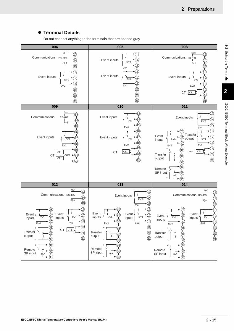
2 - 15
2 Preparations
E5CC/E5EC Digital Temperature Controllers User’s Manual (H174)
2-2 Usin
g th
e Termin
als
2
2-2-2 E5E
C Term
inal Block W
iring Exam
ple
Terminal DetailsDo not connect anything to the terminals that are shaded gray.
004 005 008
009 010 011
012 013 014
EV1
EV2
B(+)
A(−)
RS-485Communications
Event inputs
19
20
15
16
17
18
13
14
21
EV1
EV2
EV3
EV4
Event inputs
Event inputs
15
19
20
16
17
18
13
14
21
B(+)
EV1
EV2
A(−)
RS-485
CT1
Communications
Event inputs
CT19
20
15
16
17
18
13
14
21
EV1
EV2
B(+)
A(−)
RS-485Communications
Event inputs
COMCT1
CT2CT
19
20
21
15
16
17
18
13
14
EV1
EV2
EV3
EV4
CT1
Event inputs
Event inputs
CT19
20
15
16
17
18
13
14
21
CT1
EV1
EV2
EV3
EV4
EV5
EV6
+
+
−
V
mA
Transfer output
Event inputs
Remote SP input
Transfer output
Event inputs
CT+
+
−I
V31
32
33
34
35
36
30
29
28 16
17
18
13
14
21
15
19
20
B(+)
A(−)
RS-485
CT1
EV1
EV2
EV5
EV6
36
28
29
30
31
32
33
34
35
+
+
−
V
mA
Event inputs
Communications
Event inputs
CT
Remote SP input
Transfer output
+
+
−I
V20
16
17
18
13
14
21
19
15
EV3
EV4
EV1
EV2
EV5
EV6
+
+
−
V
mA
Event inputs
+
+
−I
V
Event inputs
Event inputs
Remote SP input
Transfer output
31
32
33
34
35
36
30
29
28
19
20
16
17
18
13
14
21
15
B(+)
A(−)
RS-485
EV1
EV2
EV5
EV6
+
+
−
V
mA
Communications
+
+
−I
V
Event inputs
Event inputs
Remote SP input
Transfer output
31
32
33
34
35
36
30
29
28
19
20
15
16
17
18
13
14
21

2 Preparations
2 - 16 E5CC/E5EC Digital Temperature Controllers User’s Manual (H174)
• Separate input leads and power lines in order to prevent external noise.
• Use a shielded, AWG24 to AWG18 (cross-sectional area of 0.205 to 0.823 mm2) twisted-pair cable.The stripping length is 6 to 8 mm.
• Use crimp terminals when wiring the terminals.• Use the suitable wiring material and crimp tools for crimp terminals.• Tighten the terminal screws to a torque of 0.43 to 0.58 N·m.• Use the following types of crimp terminals for M3.0 screws.
In the connection diagrams, the left side of the terminal numbers represents the inside of the Controllerand the right side represents the outside.
Power SupplyPower Consumption
• These models have reinforced insulation between the input power supply, the relay outputs, andother terminals.
InputsRefer to 2-2-1 E5CC Terminal Block Wiring Example or 2-2-2 E5EC Terminal Block Wiring Example for theterminal arrangement. When extending the thermocouple lead wires, be sure to use compensating wires thatmatch the thermocouple type. When extending the lead wires of a resistance thermometer, be sure to use wiresthat have low resistance and keep the resistance of the three lead wires the same.
2-2-3 Precautions when Wiring
2-2-4 Wiring
Input Power SupplyE5CC E5EC
Options No.: 000Options No.:
Not 000Options No.: 000
Options No.: Not 000
100 to 240 VAC, 50/60 Hz 5.2 VA max. 6.5 VA max. 6.6 VA max. 8.3 VA max.24 VAC, 50/60 Hz 3.1 VA max. 4.1 VA max. 4.1 VA max. 5.5 VA max.
24 VDC (no polarity) 1.6 W max. 2.3 W max. 2.3 W max. 3.2 W max.
5.8 mm max.
5.8 mm max.

2 - 17
2 Preparations
E5CC/E5EC Digital Temperature Controllers User’s Manual (H174)
2-2 Usin
g th
e Termin
als
2
2-2-4 Wiring
Control Outputs 1 and 2The following diagrams show the applicable outputs and their internal equivalent circuits.
E5CC
* Control outputs 1 and 2 are not isolated on models with a QQ output type specification (2 voltage outputs(for driving SSRs)).
E5EC
RX (relay output)QX (voltage output (for
driving SSR))CX (current output)
QQ (2 voltage outputs (for driving SSRs))
Output type SpecificationRX Relay output SPST-NO, 250 VAC, 3 A (resistive load), Electrical
durability: 100,000 operations
QX Voltage output (for driving SSR)
PNP, 12 VDC ±20%, 21 mA (with short-circuit protection)
CX Current output 4 to 20 or 0 to 20 mA DC, Load: 500 Ω max., Resolution: Approx. 10,000
QQ* 2 voltage outputs (for driving SSRs)
PNP, 12 VDC ±20%, 21 mA (with short-circuit protection)
RX (relay output)QX (voltage output (for
driving SSR))CX (current output)
RR (2 relay outputs)QQ (2 voltage outputs (for
driving SSRs))
QR (voltage output (for driving SSR) and relay
output)CC (2 current outputs)
A
B
+v
+
−GND
LA
B
+v
+
−
LA
B
+v
+
+
GND
L
+vL
−
A
B
C
D
C
+v
+
GNDL
−D
C
+v
+
L
−D
C
D
C
F
E
+v
+
GND
L
+v
+
GND
L
−D
C
F
E
−
+v
+
GND
L
D
C
F
E
− +v+
L
+v
+
L
D
C
F
E
−
−

2 Preparations
2 - 18 E5CC/E5EC Digital Temperature Controllers User’s Manual (H174)
* Control outputs 1 and 2 are not isolated on models with a QQ output type specification (2 voltage outputs(for driving SSRs)).
Auxiliary Outputs 1 to 4When heating/cooling control is used on the E5CC, auxiliary output 2 is the control output for cooling. Whenheating/cooling control is used on the E5EC, auxiliary output 4 is the control output for cooling unless theController has only two auxiliary outputs, in which case auxiliary output 2 is the control output for cooling.
Event InputsE5CC/E5EC models with an option number of 001 or 004 to 014 have event inputs.
E5CC
Output type SpecificationRX Relay output SPST-NO, 250 VAC, 5 A (resistive load), Electrical
durability: 100,000 operationsQX Voltage output (for driving
SSR)PNP, 12 VDC ±20%, 40 mA (with short-circuit protection)
CX Current output 4 to 20 or 0 to 20 mA DC, Load: 500 Ω max., Resolution: Approx. 10,000
RR 2 relay outputs SPST-NO, 250 VAC, 5 A (resistive load), Electrical durability: 100,000 operations
QQ* 2 voltage outputs (for driving SSRs)
PNP, 12 VDC ±20%, 21 mA (with short-circuit protection)
QR Voltage output (for driving SSRs) (control output 1)
PNP, 12 VDC ±20%, 21 mA (with short-circuit protection)
Relay output (control output 2)
SPST-NO, 250 VAC, 5 A (resistive load), Electrical durability: 100,000 operations
CC 2 current outputs 4 to 20 or 0 to 20 mA DC, Load: 500 Ω max., Resolution: Approx. 10,000
Contact inputs Non-contact inputsOption number: 001, 006, or 007
Option number: 004
Option number: 005
EV1
EV215
13
14 EV1
+
+
EV2
−
15
13
14
EV3
EV418
16
17EV3
EV4+
+
−
18
16
17
EV3
EV4
EV1
EV2
18
16
17
15
13
14EV1
EV2
EV3
EV4
+
+
−
+
+
−
18
16
17
15
13
14

2 - 19
2 Preparations
E5CC/E5EC Digital Temperature Controllers User’s Manual (H174)
2-2 Usin
g th
e Termin
als
2
2-2-4 Wiring
E5EC
• Use event inputs under the following conditions:• The outflow current is approximately 7 mA.
CT InputsE5CC/E5EC models with an option number of 001 to 003 or 008 to 012 have one or two CT inputs.
Contact inputs Non-contact inputsOption number: 004, 008 or 009
Option number: 005 or 010
Option number: 011 or 013
Option number: 012 or 014
Contact input ON: 1 kΩ max., OFF: 100 kΩ min.No-contact input ON: Residual voltage of 1.5 V max.; OFF: Leakage current of 0.1 mA max.
EV1
EV218
16
17EV1
EV2+
+
−
18
16
17
EV1
EV2
EV3
EV4
18
16
17
15
13
14EV3
EV4
EV1
EV2
+
+
−
+
+
−
18
16
17
15
13
14
EV5
EV6
EV1
EV2
EV3
EV4
18
16
17
15
13
14
30
29
28
EV5
EV6
EV3
EV4
EV1
EV2+
+
−
+
+
−
+
+
−
18
16
17
15
13
14
30
29
28
EV5
EV6
EV1
EV218
16
17
30
29
28
EV1
EV2
EV5
EV6
+
+
−
+
+
−
18
16
17
30
29
28

2 Preparations
2 - 20 E5CC/E5EC Digital Temperature Controllers User’s Manual (H174)
Transfer Output E5CC/E5EC models with an option number of 006 or 011 to 014 have a transfer output.
E5CC
E5EC
Remote SP Input E5CC/E5EC models with an option number of 007 or 011 to 014 have a remote SP input.
The remote SP input circuit is not electrically isolated from the internal circuits. Therefore, when using agrounded sensor input, do not connect the remote SP input terminals to ground. (If the remote SP inputterminals are connected to ground, errors will occur in the measured temperature as a result of leakagecurrent.)
Option number: 006
Option number: 011, 012, 013, or 014
Output type SpecificationCurrent output 4 to 20 mA DC, Load: 500 Ω max., Resolution: 10,000
Linear voltage output
1 to 5 VDC, Load: 1 kΩ min., Resolution: 10,000
Input type SpecificationCurrent input 4 to 20 or 0 to 20 mA DC with input impedance of 150 Ω max.Linear voltage output
1 to 5, 0 to 5, or 0 to 10 VDC with input impedance of 1 MΩ min.
+v
+
−
L
Current output Linear voltage output
+
−
LV
18
17
18
16
+v
+
−
L32
Current output Linear voltage output
33
+
−
L31
33
V

2 - 21
2 Preparations
E5CC/E5EC Digital Temperature Controllers User’s Manual (H174)
2-2 Usin
g th
e Termin
als
2
2-2-4 Wiring
CommunicationsRS-485E5CC/E5EC models with an option number of 002, 003, 004, 008, 009, 012, or 014 support communications.Connect the communications cable to terminals 13 and 14 to use communications with the E5CC/E5EC.
Communications Unit Connection Diagram E5CC/E5EC
• The RS-485 connection can be either one-to-one or one-to-N. A maximum of 32 Units (includingthe host computer) can be connected in one-to-N systems. The maximum total cable length is
500 m. Use a shielded, AWG24 to AWG18 (cross-sectional area of 0.205 to 0.823 mm2)twisted-pair cable.
No.1413
No.1413
RS-485
E5CC/E5EC (No.1)
RS-485
E5CC/E5EC (No.31)100 Ω
A (−)B (+)
A (−)B (+)
−+
FG
RS-485Host computer
Shield
Terminator (120 Ω, 1/2 W)
Abbreviation Abbreviation
A < B: [1] MarkA > B: [0] Space
Cross-sectional area of conductorAWG24: 0.205 mm2
AWG18: 0.823 mm2

2 Preparations
2 - 22 E5CC/E5EC Digital Temperature Controllers User’s Manual (H174)
2-3 Insulation Block Diagrams
The insulation block diagrams for the E5CC/E5EC are provided in this section.
Models with 2 Auxiliary Outputs
Model with 3 Auxiliary Outputs
Models with 4 Auxiliary Outputs
Sensor input, CT inputs, and remote SP input
Communications and event inputs
Voltage outputs (for driving SSR), current outputs, and transfer output
Relay outputs
Auxiliary output 1
Auxiliary output 2
: Reinforced insulation
: Functional insulation
Power supply
Voltage outputs (for driving SSRs), current outputs, and transfer output
Relay outputs
Auxiliary outputs 1, 2, and 3
Sensor input, CT inputs, and remote SP input
Communications and event inputs
: Reinforced insulation
: Functional insulation
Power supply
Voltage outputs (for driving SSRs), current outputs, and transfer output
Relay outputs
Auxiliary outputs 1 and 2
Auxiliary outputs 3 and 4
Sensor input, CT inputs, and remote SP input
Communications and event inputs
: Reinforced insulation
: Functional insulation
Power supply
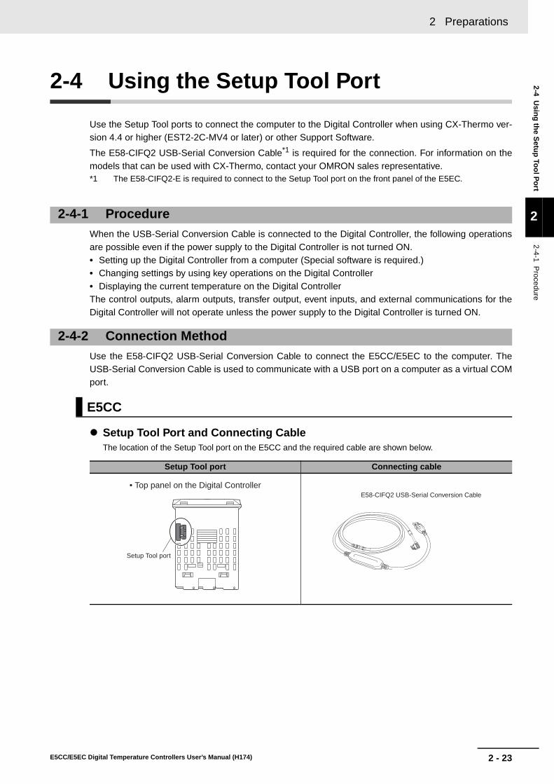
2 - 23
2 Preparations
E5CC/E5EC Digital Temperature Controllers User’s Manual (H174)
2-4 Usin
g th
e Setu
p To
ol P
ort
2
2-4-1 Procedure
2-4 Using the Setup Tool Port
Use the Setup Tool ports to connect the computer to the Digital Controller when using CX-Thermo ver-sion 4.4 or higher (EST2-2C-MV4 or later) or other Support Software.
The E58-CIFQ2 USB-Serial Conversion Cable*1 is required for the connection. For information on themodels that can be used with CX-Thermo, contact your OMRON sales representative.*1 The E58-CIFQ2-E is required to connect to the Setup Tool port on the front panel of the E5EC.
When the USB-Serial Conversion Cable is connected to the Digital Controller, the following operationsare possible even if the power supply to the Digital Controller is not turned ON.• Setting up the Digital Controller from a computer (Special software is required.)• Changing settings by using key operations on the Digital Controller• Displaying the current temperature on the Digital ControllerThe control outputs, alarm outputs, transfer output, event inputs, and external communications for theDigital Controller will not operate unless the power supply to the Digital Controller is turned ON.
Use the E58-CIFQ2 USB-Serial Conversion Cable to connect the E5CC/E5EC to the computer. TheUSB-Serial Conversion Cable is used to communicate with a USB port on a computer as a virtual COMport.
Setup Tool Port and Connecting CableThe location of the Setup Tool port on the E5CC and the required cable are shown below.
2-4-1 Procedure
2-4-2 Connection Method
E5CC
Setup Tool port Connecting cable
• Top panel on the Digital Controller
Setup Tool port
E58-CIFQ2 USB-Serial Conversion Cable

2 Preparations
2 - 24 E5CC/E5EC Digital Temperature Controllers User’s Manual (H174)
Connection Procedure
Setup Tool Ports and Connecting CablesThe locations of the Setup Tool ports on the E5EC and the required cables are shown below. There are SetupTool ports on both the top panel and front panel of the Digital Controller.
* This Cable is required only to connect to the front-panel Setup Tool port.
Connection Procedure• Top-panel Port
1 Connect the serial connector on the USB-Serial Conversion Cable to the Setup Tool port on the top panel of the Digital Controller.
E5EC
Setup Tool ports Connecting cables
1 Connect the serial connector to the Setup Tool port on the top panel of the Digital Controller.
Serial connector
Top-panel Setup Tool port
Front-panel Setup Tool port
• Top panel on the Digital Controller
• Front panel on the Digital Controller
E58-CIFQ2-E Conversion Cable*
E58-CIFQ2 USB-Serial Conversion Cable
Serial connector

2 - 25
2 Preparations
E5CC/E5EC Digital Temperature Controllers User’s Manual (H174)
2-4 Usin
g th
e Setu
p To
ol P
ort
2
2-4-2 Connection M
ethod
• Front-panel Port
Precautions for Correct Use
• Hold the connector when inserting or disconnecting the Cable.
• When connecting a connector, always make sure that it is oriented correctly. Do not force theconnector if it does not connect smoothly. Connectors may be damaged if they are connectedwith excessive force.
• Do not connect cables to both the front-panel Setup Tool port and the top-panel Setup Toolport at the same time. The Digital Controller may be damaged or may malfunction.
1 Connect the E58-CIFQ2 USB-Serial Conversion Cable to the E58-CIFQ2-E Conversion Cable.
2 Remove the Port Cover from the front-panel Setup Tool port, and then plug in the Conversion Cable.
E58-CIFQ2 USB-Serial Conversion Cable
E58-CIFQ2-E Conversion Cable
There is a triangle on the connecting surface.
Align the arrow ( ) on the small connector on the E58-CIFQ2 USB-Serial Conversion Cable with the triangle mark ( ) on the small connector on the E58-CIFQ2-E Conversion Cable.
Port Cover
Conversion Cable

2 Preparations
2 - 26 E5CC/E5EC Digital Temperature Controllers User’s Manual (H174)
1. Connect a USB connector on the computer with a Setup Tool port on the Digital Controllerusing the Cable or Cables.
2. Obtaining the DriverWhen the CX-Thermo Support Software for the Digital Controller is installed, the driver for theUSB-Serial Conversion Cable will be copied to the following folder.C:\Program Files\OMRON\Drivers\USB\E58-CIF
3. Installing the DriverInstall the driver to enable the Cable to be used with the personal computer.• Installation
When the Cable is connected with the personal computer, the OS will detect the product as a new device. Atthis time, install the driver using the Installation Wizard.
Note1: We recommend that you install the driver for each USB port on the computer at the start. The DigitalController assigns a COM port number to each USB port on the computer. If the same USB port is used,you will be able to use the same COM port number even if you use a different Cable.
2: Installation of the driver will not be completed if the installation is canceled before it is completed. Normalcommunications will not be possible unless the driver is installed completely. If the driver is not installedcompletely, uninstall it, and then install it correctly.
4. Setting Setup Tool Communications ConditionsSet the communications port (COM port) number to be used for the CX-Thermo Setup Tool to the COMport number assigned to the USB-Serial Conversion Cable.Refer to the E58-CIFQ2 USB-Serial Conversion Cable Instruction Manual and Setup Manual for detailson how to check the COM port assigned to the USB-Serial Conversion Cable.The communications conditions for Setup Tool COM ports are fixed as shown in the table below. Set thecommunications conditions for the CX-Thermo Setup Tool according to the following table
2-4-3 Installing the Driver
Parameter Set valueCommunications Unit No. 01Communications baud rate 38.4 (kbps)
Communications data length 7 (bits)
Communications stop bits 2 (bits)Communications parity Even

3 - 1E5CC/E5EC Digital Temperature Controllers User’s Manual (H174)
3
3-1 Basic Application Flow . . . . . . . . . . . . . . . . . . . . . . . . . . . . . . . . . . . . . . . . . 3-2
3-2 Power ON . . . . . . . . . . . . . . . . . . . . . . . . . . . . . . . . . . . . . . . . . . . . . . . . . . . . 3-3
3-3 Part Names, Part Functions, and Setting Levels . . . . . . . . . . . . . . . . . . . . . 3-43-3-1 Part Names and Functions . . . . . . . . . . . . . . . . . . . . . . . . . . . . . . . . . . . . . . . . 3-43-3-2 Entering Numeric Values . . . . . . . . . . . . . . . . . . . . . . . . . . . . . . . . . . . . . . . . . 3-73-3-3 Setting Levels . . . . . . . . . . . . . . . . . . . . . . . . . . . . . . . . . . . . . . . . . . . . . . . . . . 3-83-3-4 E5CC/E5EC Setting Levels . . . . . . . . . . . . . . . . . . . . . . . . . . . . . . . . . . . . . . . 3-9
3-4 Procedures after Turning ON the Power Supply . . . . . . . . . . . . . . . . . . . . 3-133-4-1 Basic Flow of Operations . . . . . . . . . . . . . . . . . . . . . . . . . . . . . . . . . . . . . . . . 3-133-4-2 Basic Procedure . . . . . . . . . . . . . . . . . . . . . . . . . . . . . . . . . . . . . . . . . . . . . . . 3-13
Part Names and Basic Procedures

3 Part Names and Basic Procedures
3 - 2 E5CC/E5EC Digital Temperature Controllers User’s Manual (H174)
3-1 Basic Application Flow
The following figure shows the basic flow for using the Digital Controller.
Power ON
• Input type
• Control method
• Alarm typeOther parameters
Set the set point.
Set the alarm set values.
Operate with the set values.
*For time-proportional operation.
Set the control hysteresis. Set the control periods* and PID constants.
ON/OFF Control PID Control
Set the input type and other basic settings.
Refer to 3-4 Procedures after Turning ON the Power Supply.

3 - 3
3 Part Names and Basic Procedures
E5CC/E5EC Digital Temperature Controllers User’s Manual (H174)
3-2 Pow
er ON
3
3-2 Power ON
Operation will start as soon as you turn ON the power supply to the E5CC/E5EC.The following default settings will be used when operation starts.
After the power comes ON, all indicators and displays will light for approximately 1 second, and then theoperation display will appear.The top display will show the PV and the bottom display will show the SP.
• Input type 5: K thermocouple• ON/OFF control• Alarm: Upper-limit alarm*• Set point: 0°C
* If the Controller is equipped with HB/HS alarm detection, it is set bydefault to detect heater alarms.
s.err 0
25 0
C
• Resistance Thermometer Connected or• Temperature Sensor Not Connected
• Thermocouple Connected
SP*The default setting is 0°C.
s.err:An input error is displayed.
The default setting of the input type is for a K thermocouple.
The operation display appears.Operation Level
Power ON
Everything lights for
approx. 1 s.
The PV that is measured by the temperature sensor is displayed.
K Thermocouple Connected: The correct temperature is
displayed.Other Thermocouple Connected: The correct temperature is
not displayed.
If you are not using a K thermocouple, set the Input Type parameter to the correct sensor type in the Initial Setting Level.Refer to step 2 on 3-13.
• Change the setting of the Input Type parameter to a resistance thermometer in the Initial Setting Level.
Or• Connect a temperature sensor.Refer to step 2 on 3-13.

3 Part Names and Basic Procedures
3 - 4 E5CC/E5EC Digital Temperature Controllers User’s Manual (H174)
3-3 Part Names, Part Functions, and Setting Levels
3-3-1 Part Names and Functions
E5CC
E5EC
Press O Key once to go to Adjustment Level.
Press O Key for at least 3 seconds to go to Initial Setting Level.
Use the M Key to change to another parameter.
Operation indicators No. 1 display
No. 2 display
Temperature unit
Use S Key to change the digit (default setting).
Top View of E5CC
Top-panel Setup Tool port
Use the U D Keys to set the parameter.
Front panel
PV or specified parameter
SP or specified parameter value
Operation indicators
Temperature unit
Front-panel Setup Tool port
Use S Key to change the digit (default setting).
Use the M Key to change to another parameter.
No. 1 display
No. 2 display
No. 3 display
Press O Key once to go to Adjustment Level.
Press O Key for at least 3 seconds to go to Initial Setting Level.
PV or specified parameter
SP or specified parameter value
Manipulated value or other value
Top View of E5EC
Use the U D Keys to set the parameter.
Top-panel Setup Tool port
Front panel

3 - 5
3 Part Names and Basic Procedures
E5CC/E5EC Digital Temperature Controllers User’s Manual (H174)
3-3 Part N
ames, P
art Fu
nctio
ns, an
d S
etting
Levels
3
3-3-1 Part N
ames and F
unctions
Displays
Display Name DescriptionE5CC: Top displayE5EC: Top display
No. 1 display Displays the process value or a monitor/setting item.
E5CC: Bottom displayE5EC: Middle display
No. 2 display Displays the set point or the value of a monitor/setting item.
E5CC: NoneE5EC: Bottom display
No. 3 Display (E5EC only)
Displays the manipulated variable, remaining soak time, multi-SP No., internal SP (ramp SP), or alarm value 1. (The value that is displayed is set in the PV/SP Display Selection parameter in the Advanced Function Setting Level.)
C or F Temperature unit
Displays the temperature unit.
Indicators
Operation indicators Name DescriptionAuxiliary outputs 1 to 4 (Only the E5EC support auxiliary output 4.)
Each indicator lights when the function that is assigned to corresponding auxiliary output (1 to 4) is ON.
Control outputs 1 and 2
Each indicator lights when the function that is assigned to corresponding control output (1 or 2) is ON. (For a current output, the indicator is not lit only for a 0% output.)
Communications writing control
This indicator lights when wiring with communications is enabled.
Manual This indicator is lit in Manual Mode.
Stop This indicator is lit while operation is stopped.
AT/ST in progress
This indicator is lit during autotuning.This indicator flashes during self-tuning.
Remote SP This indicator is lit while the SP Mode parameter is set to Remote SP Mode.This indicator flashes when there is an RSP input error in Remote SP Mode.
Setting change protection
This indicator is lit while setting change protection is ON.
(E5EC only)

3 Part Names and Basic Procedures
3 - 6 E5CC/E5EC Digital Temperature Controllers User’s Manual (H174)
Keys
Key Name Overview Description
O
Level Key Selects the setting level.
The next setting level depends on how long the key is pressed.
• In Operation Level• Press once for less than 1 second to go to
Adjustment Level.• Press for at least 3 seconds to go to Initial Setting
Level.• In Adjustment Level
• Press once for less than 1 second to go to Operation Level.
• Press for at least 3 seconds to go to Initial Setting Level.
• In Initial Setting Level• Press for at least 1 second to go to Operation
Level.• Display amov (Move to Advanced Function
Setting Level) and then enter −169 to go to Advanced Function Setting Level.
M
Mode Key Changes the parameter that is displayed within a setting level.
• Press once to go to the next parameter.• Hold to go to the previous parameter.
D
U
Down Key and Up Key
Set the value. • Hold the key to increment or decrement the value quickly.
• Any changes in settings are applied at the following times:
• After 3 seconds elapse• When the M Key is pressed• When the level is changed with the O Key
S
Shift Key (PF Key) Operates as a user-defined function key.
• Press the S to select the digit to change.You can change the PF Setting parameter to assign any of the following functions.
• Press the S Key for at least 1 second and then specify one of the following functions:RUN/STOP, auto/manual, autotuning, or canceling an alarm latch
The PF Key operates as a Digit Shift Key by default.
Example: If you set the PF Setting parameter to STOP, operation will stop when you press the PF Key for at least 1 second.
• Press the PF Key once to display the Monitor/Setting Item Level.The parameter that is displayed is set in the Monitor/Setting Item parameters in the Advanced Function Setting Level.

3 - 7
3 Part Names and Basic Procedures
E5CC/E5EC Digital Temperature Controllers User’s Manual (H174)
3-3 Part N
ames, P
art Fu
nctio
ns, an
d S
etting
Levels
3
3-3-2 Entering N
umeric V
alues
After you change a numeric value with the U D Keys, the changes are applied 1) when 3 secondselapses, 2) when the M Key is pressed, or 3) when the level is changed with the O Key.
Precautions for Correct Use
Always make sure that any changes to numeric values are applied for one of the three methodsthat are given above before you turn OFF the power supply to the E5CC/E5EC.If you only change the values with the U D Keys and turn OFF the power supply before 3seconds has elapsed, the changes will not be applied.
Press the Shift Key (PF Key) to select the digit to change.This is useful when entering a numeric value with many digits.Use this key to change levels: The digit to change will move as follows: 1s digit, 10s digit, 100s digit,1000s digit, and then back to the 1s digit. Press the U + D Keys to change the value of a digit.
Setup Tool Ports
Setup Tool port
Name Description
Top-panel Setup Tool port
Use the E58-CIFQ2 USB-Serial Conversion Cable to connect the E5CC/E5EC to the computer (i.e., the CX-Thermo Support Software).
Front-panel Setup Tool port (E5EC only)
Use the E58-CIFQ2 USB-Serial Conversion Cable and the E58-CIFQ2-E Conversion Cable to connect the E5EC to the computer (i.e., the CX-Thermo Support Software).
3-3-2 Entering Numeric Values
Applying Changes to Numeric Values
Moving between Digits (Digit Shift Key)
al-123
al-123
al-10023
al-123
al-10023
al-123
al-10023
al-123
al-10023
Press the S Key. Press the S Key.
Press the S Key.
Press the S Key. Press the S Key.

3 Part Names and Basic Procedures
3 - 8 E5CC/E5EC Digital Temperature Controllers User’s Manual (H174)
On the E5CC/E5EC, the parameters are classified into levels according to their applications. These lev-els are called setting levels. The setting levels consist of some basic setting levels and other setting lev-els.
The setting levels are described in more detail in the following tables.
Basic Setting LevelsThe basic setting levels are the levels that are used most frequently.
Other Setting LevelsThe other setting levels are used as required.
The Operation Level, Adjustment Level, Initial Setting Level, and Advanced Function Setting Levelare used most commonly. They are therefore described separately from the other setting levelsunder Basic Setting Levels, below.* To use the S Key to display the Monitor/Setting Items, change the setting of the PF Setting parameter to
pfdp.
3-3-3 Setting Levels
What Are Setting Levels?
Application of the parameters Setting level nameOperation
statusLevel that is used for operation Operation Level Operating
Level that is used for adjustments Adjustment Level Operating
Level that is used for initial settings Initial Setting Level StoppedAdvanced Function Setting Level
Application of the parameters Setting level nameOperation
statusLevel that is used for communications settings Communications Setting Level StoppedLevel that is used for manual operation Manual Control Level Operating
Level that is used to set protection Protect Level Operating
Level that is used for calibration Calibration Level StoppedLevel that is displayed when the S Key is pressed
Monitor/Setting Item Level* Operating
Setting levels
Other setting levels
Operation Level
Adjustment Level
Initial Setting Level
Advanced Function Setting Level
Manual Control Level
Protect Level
Communications Setting Level
Calibration Level
Monitor/Setting Item Level
Basic setting levels

3 - 9
3 Part Names and Basic Procedures
E5CC/E5EC Digital Temperature Controllers User’s Manual (H174)
3-3 Part N
ames, P
art Fu
nctio
ns, an
d S
etting
Levels
3
3-3-4 E5C
C/E
5EC
Setting Levels
The following figure gives an overall image of the setting levels. The setting levels consist of the basicsetting levels (shaded below) and the other setting levels (not shaded).
*1 To use a key procedure to move to Manual Control Level, set the Auto/Manual Select Addition parameter toON and set the PF Setting parameter to a-m (Auto/Manual).
*2 The No. 1 display will flash when the keys are pressed for 1 s or longer.*3 Set the PF Setting parameter to pfdp (monitor/setting items).
3-3-4 E5CC/E5EC Setting Levels
Moving between Setting Levels
Press O Key once.
Press O Key once (models with communications only).
Communications Setting Level
Advanced Function Setting Level
Power ON
Advanced settings
Initial Setting Level
Operation Level Adjustment Level
Communications settings
Monitor/Setting Item Level
O Key for at least 1 s
Press O Key once.
O Key for at least 3 s*2
O Key for at least 1 s or S Key for at least 1 s
Press S Key. Press S Key.*3
Protect Level
Calibration Level
Manual Control Level
Press O Key once.
O Key for at least 1 s
Ope
ratio
n in
pro
gres
sS
topp
ed
Used for SP, alarm values, and other basic settings and monitoring.
Used to change adjustment parameters (PID constants, control hysteresis, etc.).
Used to set protection for operations.
Used to display specified monitor and setting items.
Used to set the input type and other basic settings.
Used to set the MV manually.
Only when Manual Mode was used just before power OFF
O + M Keys for at least 1 s
Press O + M Keys for at least 3 s.*2
Level changes automatically.
O Key for at least 3 s while A-M is displayed*2 or S Key for at least 1 s*1
Enter the password (1201) for the Move to Calibration Level parameter.
Used to calibrate the E5CC/E5EC.
Release protection and then enter the password (−169) for the amoV (Move to Advanced Function Setting Level) parameter.

3 Part Names and Basic Procedures
3 - 10 E5CC/E5EC Digital Temperature Controllers User’s Manual (H174)
The following figure shows the basic setting levels (shaded).
Operation LevelThis level is displayed automatically when the power supply is turned ON.This level is used for the SP, alarm values, and other basic settings and monitoring.Normally, select this level for operation.
Adjustment LevelThis level is used to set the PID constants and to perform tuning, such as autotuning.In Adjustment Level, the settings of the parameters can be changed during operation. This is notpossible in the Initial Setting Level or Advanced Function Setting Level.
Initial Setting LevelThis level is used for the most basic settings.It is used to set the input type and other parameters.Use it to set the input type, alarm type, and other basic settings.
Advanced Function Setting LevelThis level is used for advanced settings.Use it to assign functions to the control outputs and auxiliary outputs.You will not be able to enter the Advanced Function Setting Level with the default settings.To enter the Advanced Function Setting Level, first disable Initial Setting/Communications Protectionand then enter the password (−169) at the amov (Move to Advanced Function Setting Level)parameter in the Initial Setting Level.
Basic Setting Levels
Advanced Function Setting Level
Power ON
Advanced settings
Initial Setting Level
Operation Level Adjustment Level
O Key for at least 1 s
Press O Key once.
Press O Key once.
Level changes automatically.
O Key for at least 1 s
Sto
pped
Used for SP, alarm values, and other basic settings and monitoring.
Used to change adjustment parameters (PID constants, control hysteresis, etc.).
O Key for at least 3 s (No. 1 display will flash after 1 s.)
Used to set the input type and other basic settings.
Release protection and then enter the password (−169) for the amoV (Move to Advanced Function Setting Level) parameter.
Ope
ratio
n in
pro
gres
s

3 - 11
3 Part Names and Basic Procedures
E5CC/E5EC Digital Temperature Controllers User’s Manual (H174)
3-3 Part N
ames, P
art Fu
nctio
ns, an
d S
etting
Levels
3
3-3-4 E5C
C/E
5EC
Setting Levels
Use the following procedure to move to Advanced Function Setting Level.
Step 1: Move to Protect Level.
Step 2: Display icpt (Initial Setting/Communications Protect) and set it to 0.
Step 3: Return to Operation Level.
Step 4: Return to Initial Setting Level.
Step 5: Display amoV (Move to Advanced Function Setting Level) and then enter −169.Steps 1 to 3 are necessary only the first time. Perform only steps 4 and 5 to move to AdvancedFunction Setting Level.
There are five other setting levels: Manual Control Level, Protect Level, Communications SettingLevel, Calibration Level, and Monitor/Setting Item Level.
Manual Control LevelThis level is used to set the MV manually. With the default settings, you cannot move to the ManualControl Level.• To use the S Key to move to the Manual Control Level, change the setting of the PF Setting
parameter to a-m.• To use the Level Key on the Auto/Manual Switch Display to move to the Manual Control Level, set
the Auto/Manual Switch Display Addition parameter in the Advanced Function Setting Level toON.
• To use an event input to move to the Manual Control Level, change the setting of the Event InputAssignment 1 to 6 parameter to manu.
Protect LevelThis level is used to restrict the operations that can be performed and the parameters that can bedisplayed with the front-panel keys. For example, you can prohibit changing the SP and otherparameters in the Operation Level and Adjustment Level. You can move to the Protect Level fromthe Operation Level or the Adjustment Level. To move to the Advanced Function Setting Level, youmust first cancel the protection that is set in the Protect Level.
Other Setting Levels
Advanced Function Setting Level
Power ON
Advanced settings
Step 5: Enter −169 for the amov parameter.
Move to Advanced Function Setting Level parameter
Enter −169. Default: 0
Operation LevelStep 4: O Key for at least 3 s
Step 3: Press the O + M Keys for at least 1 s.
Level changes automatically.
Initial Setting Level
Protect Level
0
icpt Initial Setting/Communications Protect
Set 0. Default: 1
Step 2: Change the parameter with the M Key and change the setting of the icpt parameter to 0.
amov0
a
Used for SP, alarm values, and other basic settings and monitoring.
Used to set the input type and other basic settings.
Used to set protection for operations.
Step 1: Press the O + M Keys simultaneously for at least 3 s.

3 Part Names and Basic Procedures
3 - 12 E5CC/E5EC Digital Temperature Controllers User’s Manual (H174)
Communications Setting LevelThis level is used to set the communications parameters. You can move to the Communications Set-ting Level from the Initial Setting Level.
Calibration LevelThis level is used to calibrate the Digital Controller. You can move to the Calibration Level from theAdvanced Function Setting Level.
Monitor/Setting Item LevelTo use the S Key to display the Monitor/Setting Items, change the setting of the PF Settingparameter to pfdp. The items that will be displayed in the Monitor/Setting Item Level are set usingthe Monitor/Setting Item 1 to 5 parameters.

3 - 13
3 Part Names and Basic Procedures
E5CC/E5EC Digital Temperature Controllers User’s Manual (H174)
3-4 Pro
cedu
res after Turn
ing
ON
the P
ow
er Su
pp
ly
3
3-4-1 Basic F
low of O
perations
3-4 Procedures after Turning ON the Power Supply
The basic flow of operations after you turn ON the power supply is shown below.
The basic procedure is given below.
1 Turn ON the power supply.
2 Set the input type.
3-4-1 Basic Flow of Operations
1. Turn ON the power supply.↓2. Set the input type.
↓3. Set the control method.
↓4. Set the alarm type.↓5. Set the set point.
↓6. Set the alarm set values.
3-4-2 Basic Procedure
25 0
s.err 0
Operation Level
s.err (input error) flashes on the display if a sensor is not connected or if the connected sensor is different from input type. Connect a sensor if one is not already connected.
25 0
in-t 5
in-t 0
in-t (IN-T): Indicates the Input Type parameter.
The default setting is 5 (5: K thermocouple at −200 to 1,300 °C).
Initial Setting Level
Initial Setting Level
The display flashes.
When you are finished, press the O (Level) Key for at least 1 second to return to the operation display.
Input Type: 0 (Pt100 resistance thermometer at −200 to 850 °C) (example)
Press the O (Level) Key for at least 3 seconds.
in-t (IN-T) will be displayed to show that the Initial Setting Level has been entered.
Press the U (Up) and D (Down) Keys to change the value.

3 Part Names and Basic Procedures
3 - 14 E5CC/E5EC Digital Temperature Controllers User’s Manual (H174)
* The default is 5.
List of Input Types
Input type Specifications Set value Temperature range in °C Temperature range in °FResistance thermometer
Pt100 0 −200 to 850 −300 to 1500
1 −199.9 to 500.0 −199.9 to 900.02 0.0 to 100.0 0.0 to 210.0
JPt100 3 −199.9 to 500.0 −199.9 to 900.0
4 0.0 to 100.0 0.0 to 210.0Thermocouple K 5* −200 to 1300 −300 to 2300
6 −20.0 to 500.0 0.0 to 900.0
J 7 −100 to 850 −100 to 15008 −20.0 to 400.0 0.0 to 750.0
T 9 −200 to 400 −300 to 700
10 −199.9 to 400.0 −199.9 to 700.0E 11 −200 to 600 −300 to 1100
L 12 −100 to 850 −100 to 1500
U 13 −200 to 400 −300 to 70014 −199.9 to 400.0 −199.9 to 700.0
N 15 −200 to 1300 −300 to 2300
R 16 0 to 1700 0 to 3000
S 17 0 to 1700 0 to 3000B 18 100 to 1800 300 to 3200
W 19 0 to 2300 0 to 3200
PLII 20 0 to 1300 0 to 2300Infrared temperature sensor ES1B
10 to 70°C 21 0 to 90 0 to 190
60 to 120°C 22 0 to 120 0 to 240
115 to 165°C 23 0 to 165 0 to 320140 to 260°C 24 0 to 260 0 to 500
Current input 4 to 20 mA 25 One of the following ranges according to the scaling:−1999 to 9999−199.9 to 999.9−19.99 to 99.99−1.999 to 9.999
0 to 20 mA 26Voltage input 1 to 5 V 27
0 to 5 V 28
0 to 10 V 29

3 - 15
3 Part Names and Basic Procedures
E5CC/E5EC Digital Temperature Controllers User’s Manual (H174)
3-4 Pro
cedu
res after Turn
ing
ON
the P
ow
er Su
pp
ly
3
3-4-2 Basic P
rocedure
3 Set the control method.
4 Set the alarm type.
* If the Controller is equipped with HB/HS alarm detection, the Alarm 1 Type is not displayed for the defaultsettings. To use alarm 1, set an output assignment to alarm 1. For details, refer to 4-6-3 Assigned OutputFunctions.
If required, use the M (Mode) Key and the U (Up) and D (Down) Keys to repeat the procedure toset alarm types for alt2 (ALT2) (Alarm 2 Type) and alt3 (ALT3) (Alarm 3 Type). (The number ofalarms that is supported depends on the model of Digital Controller. Some of the alarm parame-ters may not be displayed.)
When you are finished, press the O (Level) Key for at least 1 second to return to the operation display.
cntl (CNTL): Indicates the control method.The default setting is onof (ONOF: ON/OFF control).
Initial Setting LevelInitial Setting LevelOperation LevelOperation Level
Initial Setting Level
Initial Setting Level
The display flashes.
ON/OFF Control
PID Controlcntl (CNTL): Indicates the control method.
Press the O (Level) Key for at least 3 seconds.
Press the M (Mode) Key several times to
display cntl (CNTL).
in-t (IN-T) will be displayed to show that the Initial Setting Level has been entered.
If pid (PID control) is displayed, press the D (Down) Key to change to onof (ONOF) (ON/OFF control).
If onof (ON/OFF control) is displayed, press the U (Up) Key to change to pid (PID) (PID control).
25 0
in-t 5
cntl onof
cntl pid
Initial Setting Level
Initial Setting Level
Press the M (Mode) Key several times to display alt1 (ALT1).
Press the U (Up) and D (Down) Keys to change
the value.
Alarm type: 7 (Lower-limit alarm with standby sequence) (example)
alt1 (ALT1): Indicates the Alarm 1 Type parameter.*The default setting is 2 (2: Upper-limit alarm).
25 0
in-t 5
alt1 2
alt1 7
Initial Setting LevelInitial Setting LevelOperation LevelOperation Level
The display flashes.Press the O (Level) Key for at least 3 seconds.
in-t (IN-T) will be displayed to show that the Initial Setting Level has been entered.

3 Part Names and Basic Procedures
3 - 16 E5CC/E5EC Digital Temperature Controllers User’s Manual (H174)
Alarm Type Numbers
Alarm type No.
Alarm type Description Operation
0 Alarm function OFF
There will be no alarm outputs. ---
1 Upper- and lower-limit alarm
The alarm output is ON while the PV is equal to or higher than the upper-limit alarm point or while the PV is equal to or lower than the lower-limit alarm point.
2 Upper-limit alarm
The alarm output is ON while the PV is equal to or higher than the upper-limit alarm point.
3 Lower-limit alarm
The alarm output is ON while the PV is equal to or lower than the lower-limit alarm point.
4 Upper- and lower-limit range alarm
The alarm output is ON while the PV is equal to or lower than the upper-limit alarm point or equal to or higher than the lower-limit alarm point.
5 Upper- and lower-limit alarm with standby sequence
This alarm provides a standby sequence.The alarm output is ON while the PV is equal to or higher than the upper-limit alarm point or while the PV is equal to or lower than the lower-limit alarm point.
6 Upper-limit alarm with standby sequence
This alarm provides a standby sequence.The alarm output is ON while the PV is equal to or higher than the upper-limit alarm point.
7 Lower-limit alarm with standby sequence
This alarm provides a standby sequence.The alarm output is ON while the PV is equal to or lower than the lower-limit alarm point.
Example:
OFF Temperature
Set point (e.g., 100°C)
ON
Lower-limit alarm point (e.g., 80°C)
Upper-limit alarm point (e.g., 130°C)
Alarm value upper limit (e.g., 30°C)
Alarm value lower limit (e.g., 20°C)
ON
Example:
OFF Temperature
Alarm value upper limit (e.g., 20°C)
Set point (e.g., 100°C)
Upper-limit alarm point (e.g., 120°C)
ON
Example:
OFF Temperature
Lower-limit alarm point (e.g., 80°C)
Set point (e.g., 100°C)
Alarm value lower limit (e.g., 20°C)
Example:
OFF Temperature
ON
Set point (e.g., 100°C)
Lower-limit alarm point (e.g., 80°C)
Alarm value lower limit (e.g., 20°C)
Upper-limit alarm point (e.g., 130°C)
Alarm value upper limit (e.g., 30°C)
Example:
OFF Temperature
ON
Lower-limit alarm point (e.g., 80°C)
Set point (e.g., 100°C)
Upper-limit alarm point (e.g., 130°C)
Alarm value upper limit (e.g., 30°C)
Alarm value lower limit (e.g., 20°C)
ON
Example:
OFF Temperature
Upper-limit alarm point (e.g., 120°C)
Alarm value upper limit (e.g., 20°C)
Set point (e.g., 100°C)
ON
OFF Temperature
Lower-limit alarm point (e.g., 80°C)
Set point (e.g., 100°C)
Alarm value lower limit (e.g., 20°C)
Example:

3 - 17
3 Part Names and Basic Procedures
E5CC/E5EC Digital Temperature Controllers User’s Manual (H174)
3-4 Pro
cedu
res after Turn
ing
ON
the P
ow
er Su
pp
ly
3
3-4-2 Basic P
rocedure
8 Absolute-value upper-limit alarm
The alarm output is ON while the PV is equal to or higher than the alarm value.
9 Absolute-value lower-limit alarm
The alarm output is ON while the PV is equal to or lower than the alarm value.
10 Absolute-value upper-limit alarm with standby sequence
This alarm provides a standby sequence.The alarm output is ON while the PV is equal to or higher than the alarm value.
11 Absolute-value lower-limit alarm with standby sequence
This alarm provides a standby sequence.The alarm output is ON while the PV is equal to or lower than the alarm value.
12 Loop Burnout Alarm (LBA) (Valid only for alarm 1.)
The alarm output turns ON when the control loop is broken.
There is assumed to be a loop burnout alarm if the control deviation (SP − PV) is greater than the threshold set in the LBA Level parameter and if the PV is not reduced by at least the value set in the LBA Band parameter within a specific period of time. The LBA detection time and LBA band are set in parameters.
Alarm type No.
Alarm type Description Operation
ON
OFF0
Temperature
Upper-limit alarm point (e.g., 100°C)
Alarm value (e.g., 100°C)
Example:
ON
OFF0
Temperature
Lower-limit alarm point (e.g., 100°C)
Example:
Alarm value (e.g., 100°C)
ON
OFF0
Temperature
Upper-limit alarm point (e.g., 100°C)
Alarm value (e.g., 100°C)
Example:
ON
OFF0
Temperature
Lower-limit alarm point (e.g., 100°C)
Example:
Alarm value (e.g., 100°C)
ON
SP
MV
LBA Alarm Output
PV
100%
0%
OFF Time
Time
Time
LBA detection time
LBA band
LBA level

3 Part Names and Basic Procedures
3 - 18 E5CC/E5EC Digital Temperature Controllers User’s Manual (H174)
13 PV change rate alarm
The alarm output turns ON if the change in the PV within the specified calculation period exceeds a specific width.
The PV rate of change calculation period and the alarm value are set in parameters.
14 SP absolute-value upper-limit alarm
The alarm output is ON while the SP is equal to or higher than the alarm value.
15 SP absolute-value lower-limit alarm
The alarm output is ON while the SP is equal to or lower than the alarm value.
16 MV absolute-value upper-limit alarm
The alarm output is ON while the MV is equal to or higher than the alarm value.
17 MV absolute-value lower-limit alarm
The alarm output is ON while the MV is equal to or lower than the alarm value.
18 RSP absolute-value upper-limit alarm
The alarm output is ON while the RSP is equal to or higher than the alarm value.
19 RSP absolute-value lower-limit alarm
The alarm output is ON while the RSP is equal to or lower than the alarm value.
Alarm type No.
Alarm type Description Operation
PV
PV Change Rate Alarm Output
PV rate of change calculation period
Change rate width
ON
OFF Time
Time
ON
OFF0
SP
Upper-limit alarm point (e.g., 100°C)
Alarm value (e.g., 100°C)
Example:
ON
OFF0
SP
Lower-limit alarm point (e.g., 100°C)
Example:
Alarm value (e.g., 100°C)
ON
OFF0
MV
Upper-limit alarm point (e.g., 60%)
Alarm value (e.g., 60%)
Example for Standard Control:
ON
OFF0
MV
Lower-limit alarm point (e.g., 80%)
Example for Standard Control:
Alarm value (e.g., 80%)
ON
OFF0
RSP
Upper-limit alarm point (e.g., 100°C)
Alarm value (e.g., 100°C)
Example:
ON
OFF0
RSP
Lower-limit alarm point (e.g., 100°C)
Example:
Alarm value (e.g., 100°C)

3 - 19
3 Part Names and Basic Procedures
E5CC/E5EC Digital Temperature Controllers User’s Manual (H174)
3-4 Pro
cedu
res after Turn
ing
ON
the P
ow
er Su
pp
ly
3
3-4-2 Basic P
rocedure
5 Set the set point.
6 Set the alarm set value or values.
This concludes the procedure to set the input type, alarm type, control method, set point, and alarmset values. For information on the settings of the ON/OFF hysteresis, PID constants, HS alarm, HSalarm, and other parameters, refer to Section 4 Basic Operation or Section 5 Advanced Operations.
*Hold the U (Up) or D (Down) Key to increment or decrement the value quickly.
Operation Display
Set point: 500°C (example)
Press the U (Up) and D (Down) Keys and the S (Shift) Key to change the value.
25 0
25 500
al-1 0
al1h 0
al1l 0
Change the parameter that is displayed with the M (Mode) Key.
Operation Level
Press the M (Mode) Key several times to display al-1 (AL-1).
Alarm Type 2, 3, 6, 7, 8, 9,10, or 11 (Upper-limit Alarms and Lower-limit Alarms)
Alarm Type 1, 4, or 5 (Upper-limit and Lower-limit Alarms or Upper-limit and Lower-limit Range Alarms)
To set the alarm value upper limit, press the M (Mode) Key several times to display al1h (AL1H).
To set the alarm value lower limit, press the M (Mode) Key several times to display al1l (AL1L).

3 Part Names and Basic Procedures
3 - 20 E5CC/E5EC Digital Temperature Controllers User’s Manual (H174)

4 - 1E5CC/E5EC Digital Temperature Controllers User’s Manual (H174)
4
4-1 Moving between Setting Levels . . . . . . . . . . . . . . . . . . . . . . . . . . . . . . . . . . 4-34-1-1 Moving to the Initial Setting Level . . . . . . . . . . . . . . . . . . . . . . . . . . . . . . . . . . . 4-34-1-2 Moving to the Adjustment Level . . . . . . . . . . . . . . . . . . . . . . . . . . . . . . . . . . . . 4-44-1-3 Moving to the Protect Level . . . . . . . . . . . . . . . . . . . . . . . . . . . . . . . . . . . . . . . . 4-44-1-4 Moving to the Advanced Function Setting Level . . . . . . . . . . . . . . . . . . . . . . . . 4-54-1-5 Moving to the Communications Setting Level . . . . . . . . . . . . . . . . . . . . . . . . . . 4-7
4-2 Initial Setting Examples . . . . . . . . . . . . . . . . . . . . . . . . . . . . . . . . . . . . . . . . . 4-8
4-3 Setting the Input Type . . . . . . . . . . . . . . . . . . . . . . . . . . . . . . . . . . . . . . . . . 4-104-3-1 Input Type . . . . . . . . . . . . . . . . . . . . . . . . . . . . . . . . . . . . . . . . . . . . . . . . . . . . 4-10
4-4 Selecting the Temperature Unit . . . . . . . . . . . . . . . . . . . . . . . . . . . . . . . . . 4-124-4-1 Temperature Unit . . . . . . . . . . . . . . . . . . . . . . . . . . . . . . . . . . . . . . . . . . . . . . 4-12
4-5 Selecting PID Control or ON/OFF Control . . . . . . . . . . . . . . . . . . . . . . . . . 4-13
4-6 Setting Output Specifications . . . . . . . . . . . . . . . . . . . . . . . . . . . . . . . . . . . 4-144-6-1 Control Periods . . . . . . . . . . . . . . . . . . . . . . . . . . . . . . . . . . . . . . . . . . . . . . . . 4-144-6-2 Direct and Reverse Operation . . . . . . . . . . . . . . . . . . . . . . . . . . . . . . . . . . . . . 4-144-6-3 Assigned Output Functions . . . . . . . . . . . . . . . . . . . . . . . . . . . . . . . . . . . . . . . 4-154-6-4 Auxiliary Output Opening or Closing in Alarm . . . . . . . . . . . . . . . . . . . . . . . . 4-18
4-7 Setting the Set Point (SP) . . . . . . . . . . . . . . . . . . . . . . . . . . . . . . . . . . . . . . 4-194-7-1 Changing the SP . . . . . . . . . . . . . . . . . . . . . . . . . . . . . . . . . . . . . . . . . . . . . . . 4-19
4-8 Using ON/OFF Control . . . . . . . . . . . . . . . . . . . . . . . . . . . . . . . . . . . . . . . . . 4-204-8-1 ON/OFF Control . . . . . . . . . . . . . . . . . . . . . . . . . . . . . . . . . . . . . . . . . . . . . . . 4-204-8-2 Settings . . . . . . . . . . . . . . . . . . . . . . . . . . . . . . . . . . . . . . . . . . . . . . . . . . . . . . 4-21
4-9 Determining PID Constants (AT, ST, Manual Setup) . . . . . . . . . . . . . . . . . 4-234-9-1 AT (Auto-tuning) . . . . . . . . . . . . . . . . . . . . . . . . . . . . . . . . . . . . . . . . . . . . . . . 4-234-9-2 ST (Self-tuning) . . . . . . . . . . . . . . . . . . . . . . . . . . . . . . . . . . . . . . . . . . . . . . . . 4-254-9-3 Manual Setup . . . . . . . . . . . . . . . . . . . . . . . . . . . . . . . . . . . . . . . . . . . . . . . . . 4-28
4-10 Alarm Outputs . . . . . . . . . . . . . . . . . . . . . . . . . . . . . . . . . . . . . . . . . . . . . . . 4-304-10-1 Alarm Types . . . . . . . . . . . . . . . . . . . . . . . . . . . . . . . . . . . . . . . . . . . . . . . . . . 4-304-10-2 Alarm Values . . . . . . . . . . . . . . . . . . . . . . . . . . . . . . . . . . . . . . . . . . . . . . . . . . 4-34
4-11 Alarm Hysteresis . . . . . . . . . . . . . . . . . . . . . . . . . . . . . . . . . . . . . . . . . . . . . 4-374-11-1 Standby Sequence . . . . . . . . . . . . . . . . . . . . . . . . . . . . . . . . . . . . . . . . . . . . . 4-374-11-2 Alarm Latch . . . . . . . . . . . . . . . . . . . . . . . . . . . . . . . . . . . . . . . . . . . . . . . . . . . 4-38
Basic Operation

4 Basic Operation
4 - 2 E5CC/E5EC Digital Temperature Controllers User’s Manual (H174)
4-12 Using Heater Burnout (HB) and Heater Short (HS) Alarms . . . . . . . . . . . . 4-394-12-1 HB Alarm . . . . . . . . . . . . . . . . . . . . . . . . . . . . . . . . . . . . . . . . . . . . . . . . . . . . . 4-394-12-2 HS Alarm . . . . . . . . . . . . . . . . . . . . . . . . . . . . . . . . . . . . . . . . . . . . . . . . . . . . . 4-414-12-3 Installing Current Transformers (CT) . . . . . . . . . . . . . . . . . . . . . . . . . . . . . . . . 4-434-12-4 Calculating Detection Current Values . . . . . . . . . . . . . . . . . . . . . . . . . . . . . . . . 4-454-12-5 Application Examples . . . . . . . . . . . . . . . . . . . . . . . . . . . . . . . . . . . . . . . . . . . . 4-45
4-13 Customizing the PV/SP Display . . . . . . . . . . . . . . . . . . . . . . . . . . . . . . . . . . 4-494-13-1 PV/SP Display Selections . . . . . . . . . . . . . . . . . . . . . . . . . . . . . . . . . . . . . . . . 4-49

4 - 3
4 Basic Operation
E5CC/E5EC Digital Temperature Controllers User’s Manual (H174)
4-1 Movin
g b
etween
Settin
g L
evels
4
4-1-1 Moving to the Initial S
etting Level
4-1 Moving between Setting Levels
The Operation Level is displayed first when the power supply to the Digital Controller is turned ON. Todisplay the parameters, you must move to the following setting levels.• Operation Level (Entered when the power supply is turned ON.)• Initial Setting Level• Adjustment Level• Protect Level• Advanced Function Setting Level• Communications Setting Level
The procedures to move between the setting levels starting from the Operation Level are providedbelow.
4-1-1 Moving to the Initial Setting Level
Moving from the Operation Level to the Initial Setting Level
1 Press the O Key for at least 3 seconds in the Operation Level.The No. 1 display will flash when the key is pressed for 1 s orlonger.
Operation Level
The display will change from the Operation Level to the InitialSetting Level.
Initial Setting Level
Moving from the Initial Setting Level to the Operation Level
1 Press the O Key for at least 1 second in the Initial SettingLevel.
Initial Setting Level
The display will change from the Initial Setting Level to theOperation Level.
Operation Level
0
25
5
in-t Input Type
5
in-t
0
25 PV/SP

4 Basic Operation
4 - 4 E5CC/E5EC Digital Temperature Controllers User’s Manual (H174)
4-1-2 Moving to the Adjustment Level
Moving from the Operation Level to the Adjustment Level
1 Press the O Key for less than 1 second in the OperationLevel.
Operation Level
The display will change from the Operation Level to the AdjustmentLevel.* l.adj will be displayed only once when you move to the Adjustment
Level.
Adjustment Level
Moving from the Adjustment Level to the Operation Level
1 Press the O Key for less than 1 second in the AdjustmentLevel.
Adjustment Level
The display will change from the Adjustment Level to the OperationLevel.
Operation Level
4-1-3 Moving to the Protect Level
Moving from the Operation Level to the Protect Level
1 Press the O and M Keys simultaneously for at least 3seconds* in the Operation Level.The No. 1 display will flash when the keys are pressed for 1 s orlonger.* The key pressing time can be changed in the Move to Protect Level
Time parameter in the Advanced Function Setting Level.
Operation Level
The display will change to the Protect Level. Protect Level
Moving from the Protect Level to the Operation Level
1 Press the O and M Keys simultaneously for at least 1 secondin the Protect Level.
Protect Level
The display will change from the Protect Level to the OperationLevel.
Operation Level
0
25
l.adj
0.0
ins Process Value Input Shift
0
25 PV/SP
0
25
0
oaptOperation/AdjustmentProtect
0
oapt
0
25 PV/SP

4 - 5
4 Basic Operation
E5CC/E5EC Digital Temperature Controllers User’s Manual (H174)
4-1 Movin
g b
etween
Settin
g L
evels
4
4-1-4 Moving to the A
dvanced Function S
etting Level
To enter the Advanced Function Setting Level, you must first enter the Protect Level and change thesetting of the icpt (Initial Setting/Communications Protect) parameter to 0 (enable moving toAdvanced Function Setting Level) to clear the protection.
Clearing Protection
4-1-4 Moving to the Advanced Function Setting Level
Moving to the Advanced Function Setting Level for the First Time(i.e., with the Default Settings)
1 Press the O and M Keys simultaneously for at least 3seconds* in the Operation Level.The No. 1 display will flash when the key is pressed for 1 s orlonger.* The key pressing time can be changed in the Move to Protect Level
Time parameter in the Advanced Function Setting Level.
The display will change to the Protect Level.
Operation Level
2 Press the M Key once at the Operation/Adjustment Protectparameter.The display will change to the Initial Setting/CommunicationsProtect parameter.
Protect Level
3 Press the D or U Key at the Initial Setting/CommunicationsProtect parameter to change the set value to 0 (enable movingto Advanced Function Setting Level).Now the amoV (Move to Advanced Function Setting Level)parameter can be displayed in the Initial Setting Level.The default is 1 (disable moving to Advanced Function SettingLevel).
4 Press the O and M Keys simultaneously for at least 1 secondin the Protect Level.
Protect Level
The display will change from the Protect Level to the OperationLevel.
Operation Level
0
25
0
oaptOperation/Adjustment Protect
1
icptInitial Setting/Communications Protect
1: Moving to Advanced Function Setting Level is disabled.
0
icptInitial Setting/Communications Protect
0
25 PV/SP

4 Basic Operation
4 - 6 E5CC/E5EC Digital Temperature Controllers User’s Manual (H174)
After you have set the icpt (Initial Setting/Communications Protect) parameter to 0 (enable movingto Advanced Function Setting Level), select amov (Move to Advanced Function Setting Level) in theInitial Setting Level.
Moving to the Advanced Function Setting Level
Moving from the Advanced Function Setting Level to the Operation Level
Moving to the Advanced Function Setting Level after ClearingProtection
1 Press the O Key for at least 3 seconds in the Operation Level.The No. 1 display will flash when the key is pressed for 1 s orlonger. The display will change from the Operation Level to theInitial Setting Level.
Operation Level
2 Press the M Key several times in the Initial Setting Level todisplay amoV (Move to Advanced Function Setting Level).
Initial Setting Level
3 Press the D and U Keys at the Move to Advanced FunctionSetting Level parameter and then enter -169.* You can hold the U (Up) or D (Down) Key to increment or decrement
the set value quickly.
Initial Setting Level
4 Press M Key once or wait for 2 seconds or longer withoutdoing anything.
The display will change to the Advanced Function Setting Level. Advanced Function Setting Level
1 Press the O Key for at least 1 second in the AdvancedFunction Setting Level.The display will change from the Advanced Function Setting Levelto the Initial Setting Level.
Advanced Function Setting Level
2 Press the O Key for at least 1 second in the Initial SettingLevel.
Initial Setting Level
The display will change from the Initial Setting Level to theOperation Level.
Operation Level
0
25
5
in-t Input Type
0
amovMove to Advanced Function Setting Level
-169
amovMove to Advanced Function Setting Level−169: Password to move to Advanced Function Setting Level
off
init Parameter Initialization
off
init
5
in-t Input Type
0
25 PV/SP

4 - 7
4 Basic Operation
E5CC/E5EC Digital Temperature Controllers User’s Manual (H174)
4-1 Movin
g b
etween
Settin
g L
evels
4
4-1-5 Moving to the C
omm
unications Setting Level
Moving from the Operation Level to the Communications Setting Level
Moving from the Communications Setting Level to the Operation Level
4-1-5 Moving to the Communications Setting Level
1 Press the O Key for at least 3 seconds in the Operation Level.The No. 1 display will flash when the keys are pressed for 1 s orlonger. The display will change from the Operation Level to theInitial Setting Level.
Operation Level
2 Press the O Key for less than 1 second in the Initial SettingLevel.
Initial Setting Level
The display will change from the Initial Setting Level to theCommunications Setting Level.
Communications Setting Level
1 Press the O Key for less than 1 second in theCommunications Setting Level.The display will change from the Communications Setting Level tothe Initial Setting Level.
Communications Setting Level
2 Press the O Key for at least 1 second in the Initial SettingLevel.
Initial Setting Level
The display will change from the Initial Setting Level to theOperation Level.
Operation Level
0
25
5
in-t Input Type
cwf
psel Protocol Setting
cwf
psel
5
in-t Input Type
0
25 PV/SP

4 Basic Operation
4 - 8 E5CC/E5EC Digital Temperature Controllers User’s Manual (H174)
4-2 Initial Setting Examples
Initial hardware setup, including the sensor input type, alarm types, control periods, and other settings,is done using parameter displays. The O and M Keys are used to switch between parameters, and theamount of time that you press the keys determines which parameter you move to.This section describes two typical examples.
* If the Controller is equipped with HB/HS alarm detection, the Alarm 1 Type is not displayed for the defaultsettings. To use alarm 1, set an output assignment to alarm 1. For details, refer to 4-6-3 Assigned OutputFunctions.
Explanation of Examples
Example 1
0
in-t
onof
intl
100
in-h
0
in-l
onof
intl0
25
MM
M
Changing Parameters
A image means that there are parameters. Continue pressing the M Key to change parameters until you reach the intended parameter.
Changing Numbers
Numeric data and selections in each screen can be changed by using the U and D Keys.
0
25
M
M
M
M
M
M
Initial Setting Level
Operation Level
5
in-t
onof
cntl
2
alt1
100
25
run
r-5
20
al-1
100
20
onof
pid
run
stop
Input type: 5 (K thermocouple, −200°C to 1,300°C)Control method: ON/OFF controlAlarm type: 2 (upper limit)Alarm value 1: 20°C (deviation)Set point: 100°C
Setup Procedure
Power ON
Set input specifications
Set control specifications
Set alarm type
Set SP and alarm values
Start operation
Power ON
Operation Level
PV/SP
Press the O Key for at least 3 s.
Control stops.
Initial Setting Level
Input Type: 5
Check that control method is ON/OFF control.
ON/OFF control:PID control:
Check alarm type.
Check input type.
Alarm 1 Type*: 2
Press the O Key for at least 1 s.
Control starts.Operation Level
Use the U and D Keys to set the SP to 100°C.
PV/SP:
Confirm that control is running.
RunningStopped:
Use the U and D Keys to set the alarm value to 20°C.
Alarm Value 1:
Start operation.
An s.err error will be displayed if the power supply is turned ON before the sensor is connected.

4 - 9
4 Basic Operation
E5CC/E5EC Digital Temperature Controllers User’s Manual (H174)
4-2 Initial S
etting
Exam
ples
4
* If the Controller is equipped with HB/HS alarm detection, the Alarm 1 Type is not displayed for the defaultsettings. To use alarm 1, set an output assignment to alarm 1. For details, refer to 4-6-3 Assigned OutputFunctions.
Example 2
0
25
M
M
M
M
9
in-t
pid
cntl
2
alt1
150
25
M
off
st
20
cp
off
at
M
M
M
150
25
run
r-5
30
al-1
Set SP
9
20
30
2
150
onof
pid
on
off
off
run
stop
Input type: 9 (T thermocouple, −200°C to 400°C)Control method: PID controlPID constants found using auto-tuning (AT).Alarm type: 2 (upper limit)Alarm value 1: 30°C Set point: 150°C
Setup Procedure
Power ON
Initial Setting Level
Set input specifications
Set control specifications
Set alarm type
Adjustment Level
AT execution
(When PID control is selected)
Operation Level
Set alarm value
Start operation
Power ON
Operation Level
PV/SP
Press the O Key for at least 3 s.
Control stops.Initial Setting Level
Use the U and D Keys to select the input type.
Input Type:
Use the U and D Keys to select PID control.
ON/OFF control:
Use the U and D Keys to set ST to OFF.
To execute ST:
PID control:
To cancel ST:
Check the control period.
Control Period (Heat)(Unit: Seconds)
Check the alarm type.
Alarm 1 Type*:
For PID, set pid.
It is recommended that 20 seconds be set for a relay output and 2 seconds for an SSR voltage output.
Press the O Key for at least 1 s.
Operation Level
Use the U and D Keys to set the SP to 150°C.
PV/SP:
Adjustment Level
Execute AT. To execute 100%AT:
To cancel AT:
Press the O Key (for less than 1 s).
Press the O Key (for less than 1 s).
Control starts.
Operation Level
Confirm that the set point is 150°C.
PV/SP
Confirm that control is running.
RunningStopped
Use the U and D Keys to set the alarm value to 30°C.
Alarm Value 1
Start operation.
at-1To execute 40%AT:
at-2
Operation Level
An s.err error will be displayed if the power supply is turned ON before the sensor is connected.
The TUNE indicator will light during autotuning.

4 Basic Operation
4 - 10 E5CC/E5EC Digital Temperature Controllers User’s Manual (H174)
4-3 Setting the Input Type
The Controller supports four input types: resistance thermometer, thermocouple, infrared temperaturesensor, and analog inputs. Set the input type that matches the sensor that is used.
Additional Information
Changes that are made with key operations are applied when the O or M Key is pressed. Theyare also applied if you do nothing for 3 seconds or longer.
4-3-1 Input Type
The following example shows how to set a K thermocouple for −20.0 to500.0°C (input type 6).
Operating Procedure
1 Press the O Key for at least 3 seconds to move from theOperation Level to the Initial Setting Level. The in-t (InputType) parameter will be displayed.
Initial Setting Level
2 Press the U or D Key to select 6 (K thermocouple at −20.0 to500.0°C).The default is 5 (5: K thermocouple at −200 to 1,300°C).
5
in-t Input Type
6
in-t

4 - 11
4 Basic Operation
E5CC/E5EC Digital Temperature Controllers User’s Manual (H174)
4-3 Settin
g th
e Inp
ut Typ
e
4
4-3-1 Input Type
List of Input Types
The default is 5.
Precautions for Correct Use
s.err (S.ERR: input error) flashes on the display if a sensor is not connected or if the connectedsensor is different from input type. Connect a sensor if one is not already connected.
Specifications Set value Temperature range in °C Temperature range in °F
Resistance thermometer
Pt100 0 −200 to 850 −300 to 1500
1 −199.9 to 500.0 −199.9 to 900.0
2 0.0 to 100.0 0.0 to 210.0
JPt100 3 −199.9 to 500.0 −199.9 to 900.0
4 0.0 to 100.0 0.0 to 210.0
Thermocouple
K 5 −200 to 1300 −300 to 2300
6 −20.0 to 500.0 0.0 to 900.0
J 7 −100 to 850 −100 to 1500
8 −20.0 to 400.0 0.0 to 750.0
T 9 −200 to 400 −300 to 700
10 −199.9 to 400.0 −199.9 to 700.0
E 11 −200 to 600 −300 to 1100
L 12 −100 to 850 −100 to 1500
U 13 −200 to 400 −300 to 700
14 −199.9 to 400.0 −199.9 to 700.0
N 15 −200 to 1300 −300 to 2300
R 16 0 to 1700 0 to 3000
S 17 0 to 1700 0 to 3000
B 18 100 to 1800 300 to 3200
W 19 0 to 2300 0 to 3200
PLII 20 0 to 1300 0 to 2300
Infrared temperature sensor ES1B
10 to 70°C 21 0 to 90 0 to 190
60 to 120°C 22 0 to 120 0 to 240
115 to 165°C 23 0 to 165 0 to 320
140 to 260°C 24 0 to 260 0 to 500
Current output4 to 20 mA 25 One of the following ranges according to the scaling:
−1999 to 9999−199.9 to 999.9−19.99 to 99.99−1.999 to 9.999
0 to 20 mA 26
Voltage input
1 to 5 V 27
0 to 5 V 28
0 to 10 V 29
0.0
s.err
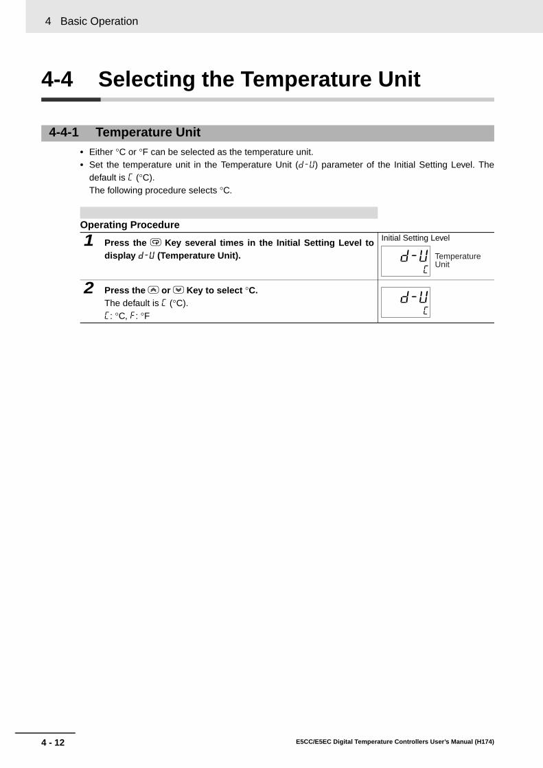
4 Basic Operation
4 - 12 E5CC/E5EC Digital Temperature Controllers User’s Manual (H174)
4-4 Selecting the Temperature Unit
• Either °C or °F can be selected as the temperature unit.• Set the temperature unit in the Temperature Unit (d-u) parameter of the Initial Setting Level. The
default is c (°C). The following procedure selects °C.
4-4-1 Temperature Unit
Operating Procedure
1 Press the M Key several times in the Initial Setting Level todisplay d-u (Temperature Unit).
Initial Setting Level
2 Press the U or D Key to select °C.The default is c (°C).c: °C, f: °F
c
d-u Temperature Unit
c
d-u

4 - 13
4 Basic Operation
E5CC/E5EC Digital Temperature Controllers User’s Manual (H174)
4-5 Selectin
g P
ID C
on
trol o
r ON
/OF
F C
on
trol
4
4-5 Selecting PID Control or ON/OFF Control
Two control methods are supported: 2-PID control and ON/OFF control. Switching between 2-PID con-trol and ON/OFF control is executed by means of the PID ON/OFF parameter in the initial setting level.When this parameter is set to pid, 2-PID control is selected, and when set to onof, ON/OFF control, isselected. The default is onof.
2-PID ControlPID control is set by AT (auto-tuning), ST (self-tuning), or manual setting.For PID control, set the PID constants in the Proportional Band (p), Integral Time (i), and DerivativeTime (d) parameters.For heating and cooling control, also set the Proportional Band (Cooling) (c-p), Integral Time(Cooling) (c-i), and Derivative Time (Cooling) (c-d).
ON/OFF ControlIn ON/OFF control, the control output is turned ON when the process value is lower than the currentset point, and the control output is turned OFF when the process value is higher than the current setpoint (reverse operation).

4 Basic Operation
4 - 14 E5CC/E5EC Digital Temperature Controllers User’s Manual (H174)
4-6 Setting Output Specifications
4-6-1 Control Periods
• Set the output periods (control periods). Though a shorter period provides better control performance, it is recommended that the control period be set to 20 seconds or longer for a relay output to preserve the service life of the relay. After the settings have been made in the initial setup, readjust the control period, as required, by means such as trial operation.
• Set the control periods in the Control Period (Heating) and Control Period (Cooling) parameters in the Initial Setting Level. The default is 20 seconds for a relay output and 2 seconds for a voltage output (for driving SSR).
• The control periods are used only for PID control.• The Control Period (Cooling) parameter is used only for heating/cooling
control.• When control output is used as a current output, the Control Period parameter
cannot be used.
4-6-2 Direct and Reverse Operation
• Direct operation increases the manipulated variable whenever the process value increases. Reverse operation decreases the manipulated variable whenever the process value increases.
For example, when the process value (PV) is lower than the set point (SP) in a heating control system, the manipulated variable increases according to the difference between the PV and SP. Accordingly, reverse operation is used in a heating control system. Direct operation is used in a cooling control system, in which the operation is the opposite of a heating control system. The Control Output 1 Assignment is set to o (control output (heating)) for either direct or reverse operation. • Direct/reverse operation is set in the Direct/Reverse Operation parameter in
the Initial Setting Level. The default is or-r (reverse operation).
cp
c-cp
Control Period (Heating)
Control Period (Cooling)
orev
100%
0%
100%
0%
Manipulated variable Manipulated variable
Low temperature
Set Value High temperature
Low temperature
Set Value High temperature
Direct operation Reverse operation

4 - 15
4 Basic Operation
E5CC/E5EC Digital Temperature Controllers User’s Manual (H174)
4-6 Settin
g O
utp
ut S
pecificatio
ns
4
4-6-3 Assigned O
utput Functions
• Function assignments can be changed by changing the settings for control and auxiliary outputassignments.
• The default function assignments for each output are shown below.
• Refer to page 6-73 for the functions that can be assigned to the outputs.• Each output is automatically initialized as shown below by changing the control mode between
standard and heating/cooling.
In this example, direct/reverse operation, and control period(heating) parameters are checked.Direct/reverse operation = or-r (reverse operation)Control period (heating) = 20 (seconds)
Operating Procedure• Setting the Control Period (Heating) Parameter
1 Press the M Key several times in the Initial Setting Level todisplay cp (Control Period (Heating)).
Initial Setting Level
2 Press the U or D Key to set the value to 20.The default for a relay output is 20 seconds.
• Setting Direct/Reverse Operation
1 Press the M Key several times in the Initial Setting Level todisplay orev (Direct/Reverse Operation).
Initial Setting Level
2 Press the U or D Key to select or-r (Reverse Operation).The default is or-r (Reverse Operation).
4-6-3 Assigned Output Functions
Parameter name Display Initial statusControl Output 1 Assignment out1 Control output
(heating)
Control Output 2 Assignment out2 Not assigned.Auxiliary Output 1 Assignment sub1 Alarm 1*
Auxiliary Output 2 Assignment sub2 Alarm 2
Auxiliary Output 3 Assignment sub3 Alarm 3Auxiliary Output 4 Assignment (E5EC only)
sub4 Alarm 4
20
cp Control Period (Heating)
20
cp
or-r
orev Direct/Reverse Operation
or-r
orev

4 Basic Operation
4 - 16 E5CC/E5EC Digital Temperature Controllers User’s Manual (H174)
Assigned Output FunctionsControllers with Three or Fewer Auxiliary Outputs
Controllers with Four Auxiliary Outputs
* If the Controller is equipped with HB/HS alarm detection, it is set by default to detect heater alarms (HA).Therefore, the alarm 1 function is disabled and the Alarm 1 Type is not displayed. To enable alarm 1, set anoutput assignment to alarm 1. If the Program Pattern parameter is changed to a setting other than OFF,Auxiliary Output 1 Assignment parameter is set as the program end output.
AlarmsIt will be specified in this section when an alarm must be assigned, i.e., when an alarm must be setfor the Control Output 1 or 2 Assignment parameters, or for the Auxiliary Output 1 to 4 Assignmentparameters. For example, if alarm 1 is set for the Control Output 1 Assignment parameter, thenalarm 1 has been assigned.
Assigning a work bit to either control output 1 or 2 or to auxiliary output 1 to 4 is also considered tobe the same as assigning an alarm. For example, if work bit 1 is set for the Auxiliary Output 1Assignment parameter, then alarms 1 to 4 have been assigned.
Parameter name DisplayWithout control output 2 With control output 2
Standard Heating/cooling Standard Heating/coolingControl Output 1 Assignment
out1 Control output (heating)
Control output (heating)
Control output (heating)
Control output (heating)
Control Output 2 Assignment
out2 --- --- Not assigned. Control output (cooling)
Auxiliary Output 1 Assignment
sub1 Alarm 1* Alarm 1* Alarm 1* Alarm 1*
Auxiliary Output 2 Assignment
sub2 Alarm 2 Control output (cooling)
Alarm 2 Alarm 2
Auxiliary Output 3 Assignment
sub3 Alarm 3 Alarm 3 Alarm 3 Alarm 3
Parameter name DisplayWithout control output 2 With control output 2
Standard Heating/cooling Standard Heating/coolingControl Output 1 Assignment
out1 Control output (heating)
Control output (heating)
Control output (heating)
Control output (heating)
Control Output 2 Assignment
out2 --- --- Not assigned. Control output (cooling)
Auxiliary Output 1 Assignment
sub1 Alarm 1* Alarm 1* Alarm 1* Alarm 1*
Auxiliary Output 2 Assignment
sub2 Alarm 2 Alarm 2 Alarm 2 Alarm 2
Auxiliary Output 3 Assignment
sub3 Alarm 3 Alarm 3 Alarm 3 Alarm 3
Auxiliary Output 4 Assignment
sub4 Alarm 4 Control output (cooling)
Alarm 4 Alarm 4

4 - 17
4 Basic Operation
E5CC/E5EC Digital Temperature Controllers User’s Manual (H174)
4-6 Settin
g O
utp
ut S
pecificatio
ns
4
4-6-3 Assigned O
utput Functions
Assign the control outputs and auxiliary outputs.Control output 1: Control output (heating)Control output 2: Control output (cooling)Auxiliary output 1: Alarm 1Auxiliary output 2: Alarm 2
Operating Procedure• Setting Heating/Cooling Control
1 Press the M Key several times in the Initial Setting Level todisplay s-hc (Standard or Heating/Cooling).
Initial Setting Level
2 Press the U or D Key to set the parameter to h-c.The default is stnd (standard).
* Use the following procedures to check the output assignments. The outputassignments are changed automatically when you change between stan-dard and heating/cooling control. You do not have to set them.
• Setting Control Output 1
1 Press the M Key several times in the Advanced FunctionSetting Level to display out1 (Control Output 1 Assignment).
Advanced Function Setting Level
2 Set the parameter to o (Control Output (Heating)).The default is o (Control Output (Heating)).
• Setting Control Output 2
1 Press the M Key several times in the Advanced FunctionSetting Level to display out2 (Control Output 2 Assignment).
Advanced Function Setting Level
2 Set the parameter to c-o (Control Output (Cooling)).As soon as you select h-c (Heating/Cooling) for the Standard orHeating/Cooling parameter, the setting of this parameter isautomatically changed to c-o (Control Output (Cooling)).
• Setting Auxiliary Output 1
1 Press the M Key several times in the Advanced FunctionSetting Level to display sub1 (Auxiliary Output 1 Assignment).
Advanced Function Setting Level
2 Press the U or D Key to set the parameter to alm1.The default is alm1 (Alarm 1).If the Controller is equipped with HB/HS alarm detection, thisparameter is set by default to ha (heater alarm).
stnd
5-hc Standard or Heating/Cooling
h-c
5-hc
o
out1 Control Output 1 Assignment
o
out1
c-o
out2 Control Output 2 Assignment
c-o
out2
alm1
sub1 Auxiliary Output 1 Assignment
alm1
sub1

4 Basic Operation
4 - 18 E5CC/E5EC Digital Temperature Controllers User’s Manual (H174)
• When "close in alarm" is set, the status of the auxiliary output is output unchanged. When "open inalarm" is set, the status of the auxiliary output function is reversed before being output.
• Each auxiliary output can be set independently.• These settings are made in the Auxiliary Output 1 to 4 Open in Alarm parameters (Advanced
Function Setting Level).• The default is n-o: Close in Alarm.
• The alarm output will turn OFF (i.e., the relay contacts will open) when power is interrupted and forabout two seconds after the power is turned ON regardless of the setting of the Auxiliary Output 1 to4 Open in Alarm parameter.
• Setting Auxiliary Output 2
1 Press the M Key several times in the Advanced FunctionSetting Level to display sub2 (Auxiliary Output 2 Assignment).
Advanced Function Setting Level
2 Press the U or D Key to set the parameter to alm2.The default is alm2 (Alarm 2).
4-6-4 Auxiliary Output Opening or Closing in Alarm
Auxiliary output functions 1 to 4
Auxiliary outputIndicators
(SUB1 to SUB4)Close in Alarm (n-o)
ON ON Lit
OFF OFF Not lit
Open in Alarm (n-c)
ON OFF Lit
OFF ON Not lit
alm2
sub2 Auxiliary Output 2 Assignment
alm2
sub2

4 - 19
4 Basic Operation
E5CC/E5EC Digital Temperature Controllers User’s Manual (H174)
4-7 Settin
g th
e Set P
oin
t (SP
)
4
4-7-1 Changing the S
P
4-7 Setting the Set Point (SP)
• The set point cannot be changed when the Operation/Adjustment Protect parameter is set to 3. Fordetails, refer to 5-7 Using the Key Protect Level.
• To change the set point, press the U or D Key in the PV/SP parameter (Operation Level) or for theSP/SP (character display) display in the Operation Level, and set the desired set value. The new setpoint is selected three seconds after you have specified the new value.
• Multi-SP is used to switch between eight set points. For details, refer to 5-4 Using Event Inputs fordetails.
Additional Information
• If there are a lot of digits in a numeric value, you can use the S (Shift Key) to select the digit tochange before you change the value of the digit.
Example: Changing 1,000°C to 1,200°C
Operation Level The Operation Level is displayed when the power is turned ON. For the default setting, the No. 1 display shows the PV, the No. 2 display shows the SP, and the No. 3 display (E5EC only) shows the MV.
The contents that is set in the PV/SP Display Screen Selection parameter in the Advanced Function Setting Level are displayed.For details, refer to 4-13-1 PV/SP Display Selections.
4-7-1 Changing the SP
In this example, the set point is changed from 0°C to 200°C.
Operating Procedure
1 Press the U or D Key in the Operation Level to set the SP to200. The default SP is 0°C.
Operation Level
1 Press S Key three times.The third digit will flash.
Operation Level
2 Press the U Key to set the value to 1200. Operation Level
0
20
0
50.0
20
200
30
1000
30
1200
30

4 Basic Operation
4 - 20 E5CC/E5EC Digital Temperature Controllers User’s Manual (H174)
4-8 Using ON/OFF Control
In ON/OFF control, the control output turns OFF when the temperature being controlled reaches thepreset set point. When the manipulated variable turns OFF, the temperature begins to fall and the con-trol turns ON again. This operation is repeated over a certain temperature range. At this time, howmuch the temperature must fall before control turns ON again is determined by the Hysteresis (Heating)parameter. Also, what direction the manipulated variable must be adjusted in response to an increaseor decrease in the process value is determined by the Direct/Reverse Operation parameter.
• Switching between 2-PID control and ON/OFF control is performed using the PID ON/OFF parameterin the Initial Setting Level. When this parameter is set to pid, 2-PID control is selected, and when it isset to onof, ON/OFF control is selected. The default is onof.
Hysteresis• With ON/OFF control, hysteresis is used to stabilize operation when switching between ON and
OFF. The control output (heating) and control output (cooling) functions are set in the Hysteresis(Heating) and Hysteresis (Cooling) parameters, respectively.
• In standard control (heating or cooling control), the setting of the Hysteresis (Heating) parameterin the Adjustment Level is used as the hysteresis regardless of whether the control type is heatingcontrol or cooling control.
4-8-1 ON/OFF Control
Hysteresis
Reverse operation
OFF OFFOFF
Time
ONON ONON
SP
Heater0
Temperature

4 - 21
4 Basic Operation
E5CC/E5EC Digital Temperature Controllers User’s Manual (H174)
4-8 Usin
g O
N/O
FF
Co
ntro
l
4
4-8-2 Settings
Parameters
To execute ON/OFF control, set the Set Point, PID ON/OFF, and Hysteresis parameters.
Setting the PID ON/OFF Parameter
Setting the SP
Display Parameter Application Levels-hc Standard or
Heating/CoolingSpecifying control method
Initial Setting Level
cntl PID ON/OFF Specifying control method
Initial Setting Level
oreV Direct/Reverse Operation
Specifying control method
Initial Setting Level
c-db Dead Band Heating/cooling control
Adjustment Level
hys Hysteresis (Heating) ON/OFF control Adjustment Level
chys Hysteresis (Cooling) ON/OFF control Adjustment Level
4-8-2 Settings
Confirm that the PID ON/OFF parameter is set to onof in the Initial Set-ting Level.
Operating Procedure
1 Press the M Key several times in the Initial Setting Level todisplay cntl (PID ON/OFF).The default is onof (ON/OFF control).
Initial Setting Level
In this example, the set point is set to 200°C. The set value (i.e., the SP)is shown at the bottom of the display.
Operating Procedure
1 Select PV/SP in the Operation Level. Operation Level
2 Press the U or D Key to set the SP to 200.The default is 0.The new set value can be saved by pressing the M Key, or it will gointo effect after 3 seconds has elapsed.
PID ON/OFF
onof
cntl
100
25 PV/SP
200
25

4 Basic Operation
4 - 22 E5CC/E5EC Digital Temperature Controllers User’s Manual (H174)
Setting the Hysteresis
Set the hysteresis to 2.0°C.
Operating Procedure
1 Press the M Key several times in the Adjustment Level todisplay hys (Hysteresis (Heating)).
Adjustment Level
2 Press the U or D Key to set the hysteresis to 2.0.The default is 1.0.The new set value can be saved by pressing the M Key, or it will gointo effect after 3 seconds has elapsed.
1.0
hys Hysteresis (Heating)
2.0
hys

4 - 23
4 Basic Operation
E5CC/E5EC Digital Temperature Controllers User’s Manual (H174)
4-9 Determ
inin
g P
ID C
on
stants (A
T, ST, M
anu
al Setu
p)
4
4-9-1 AT (A
uto-tuning)
4-9 Determining PID Constants(AT, ST, Manual Setup)
AT OperationsAT is started when either at-2 (100% AT) or at-1 (40% AT) is specified for the AT Execute/Cancelparameter.The TUNE indicator will light during execution.Only the Communications Writing, RUN/STOP, AT Execution/Cancel, and Program Start parameterscan be changed during AT execution. Other parameters cannot be changed.
AT Calculated GainThe AT Calculated Gain parameter sets the gain for when PID values are calculated using AT. Whenemphasizing response, decrease the set value. When emphasizing stability, increase the set value.
AT HysteresisThe AT Hysteresis parameter sets the hysteresis when switching ON and OFF for the limit cycleoperation during auto-tuning.
4-9-1 AT (Auto-tuning)
• When AT is executed, the optimum PID constants for the set point at that time are set automatically. A method (called the limit cycle method) for forcibly changing the manipulated variable and finding the characteristics of the control object is employed.
• Either 40% AT or 100% AT can be selected depending on the width of MV variation in the limit cycle. In the AT Execute/Cancel parameter, specify at-2 (100% AT) or at-1 (40% AT). To cancel AT, specify off (AT cancel).
• Only 100% AT can be executed for heating and cooling control.• If the Heating/Cooling Tuning Method parameter is set to any value other than
0 (same as heating control), the PID constants are set automatically for both heating control and cooling control.
• AT cannot be executed when control has stopped or during ON/OFF control.• The results of autotuning are saved in the following parameters in the
Adjustment Level: Proportional Band (P), Integral Time (I), Derivative Time (D), Proportional Band (Cooling) (C-P), Integral Time (Cooling) (C-I), and Derivative Time (Cooling) (C-D).
Adjustment Level
at
8.0
p
233
i
40
d
Proportional Band (Cooling)
8.0
c-p
Integral Time (Cooling)
233
c-i
Derivative Time (Cooling)
40
c-d
Proportional Band
Integral Time
Derivative Time

4 Basic Operation
4 - 24 E5CC/E5EC Digital Temperature Controllers User’s Manual (H174)
Limit Cycle MV AmplitudeThe Limit Cycle MV Amplitude parameter sets the MV amplitude for limit cycle operation duringauto-tuning.* This setting is disabled for 100% AT.
40% AT• The width of MV variation in the limit cycle can be changed in the Limit Cycle MV Amplitude
parameter, but the AT execution time may be longer than for 100% AT. The limit cycle timing variesaccording to whether the deviation (DV) at the start of auto-tuning execution is less than 10% FS.
100% AT• Operation will be as shown in the following diagram, regardless of the deviation (DV) at the start of
AT execution. To shorten the AT execution time, select 100% AT.
This procedure executes 40%AT.
Operating Procedure
1 Press the M Key several times in the Adjustment Level to dis-play at (AT Execute/Cancel).
Adjustment Level
2 Press the U or D Key to select at-1 (40% AT execute).* The TUNE indicator will light during autotuning.
3 When AT ends, the AT Execute/Cancel parameter is set to OFF. Adjustment Level
SP
PV
AT started AT ended
Time
Limit Cycle MV Amplitude 40%
Deviation ≥ 10% FS
Deviation: 10% FS
Time
Deviation < 10% FS
SP
PV
AT started AT ended
Limit Cycle MV Amplitude 40%
Deviation: 10% FS
* The Limit Cycle MV Amplitude parameter is disabled.
SP
PV
AT started AT ended
Time
Limit Cycle MV Amplitude 100%
off
at AT Execute/ Cancel
at-1
at
off
at AT Execute/ Cancel

4 - 25
4 Basic Operation
E5CC/E5EC Digital Temperature Controllers User’s Manual (H174)
4-9 Determ
inin
g P
ID C
on
stants (A
T, ST, M
anu
al Setu
p)
4
4-9-2 ST
(Self-tuning)
Additional Information
PID ConstantsWhen control characteristics are already known, PID constants can be set directly to adjustcontrol. The PID constants are set in the following parameters in the Adjustment Level:Proportional Band (P), Integral Time (I), Derivative Time (D), Proportional Band (Cooling) (C-P),Integral Time (Cooling) (C-I), and Derivative Time (Cooling) (C-D).
Startup ConditionsSelf-tuning by step response tuning (SRT) is started when the following conditions are met afterprogram execution is started and the set point is changed.
*1 The previous SRT-implemented set point is the set point that was used for calculating the PID constantsfor the previous SRT.
*2 In this state, the measurement point is within the ST stable range.
4-9-2 ST (Self-tuning)
ST (self-tuning) is a function that finds PID constants by using step response tuning (SRT) when Digital Controller operation begins or when the set point is changed.Once the PID constants have been calculated, ST is not executed when the next control operation is started as long as the set point remains unchanged.ST (self-tuning) is enabled when the ST parameter is set to ON in the Initial Setting Level.When executing self-tuning, turn ON power for the load (e.g., heater) at the same time as or before supplying power to the Digital Controller. If power is turned ON for the Digital Controller before turning ON power for the load, self-tuning will not be performed properly and optimum control will not be achieved.
This procedure executes self-tuning (ST).
Operating Procedure
1 Press the M Key several times in the Initial Setting Level todisplay ST.
Initial Setting Level
2 Press the U or D Key to select on (ST ON).The default is ON.
* The TUNE indicator will flash during ST execution.
At start of operation When set point is changed1. The set point at the start of operation differs from
the set point when the previous SRT was
executed.*1
2. The difference between the temperature at the start of operation and the set point is greater than the larger of the following two: (Present proportional band × 1.27 + 4°C) and the ST stable range.
3. The temperature at the start of operation is lower than the set point during reverse operation, and is larger than the set point during direct operation.
4. There is no reset from input errors.
1. The new set point differs from the set point used
when the previous SRT was executed. *1
2. The set point change width is greater than the larger of the following two: (Present proportional band × 1.27 + 4°C) and the ST stable range.
3. During reverse operation, the new set point is larger than the set point before the change; and during direct operation, the new set point is smaller than the set point before the change.
4. The temperature is stable. *2 (Equilibrium with the output amount at 0% when
the power is turned ON is also all right.)*3
st
ST
on
st
on
st

4 Basic Operation
4 - 26 E5CC/E5EC Digital Temperature Controllers User’s Manual (H174)
*3 In this state, the change width of the PV every 60 seconds is within the ST stable range or less.
In the following instances, PID constants are not changed by self-tuning (ST) for the present setpoint.(1) When the PID constants have been changed manually with ST set to ON.(2) When auto-tuning (AT) has been executed.To execute self-tuning again after completing the above operations, set the ST parameter to OFFand then set it to ON again.
ST Stable Range
The ST stable range determines the condition under which ST (self-tun-ing) functions.
This procedure sets the ST stable range to 20.0°C.
Operating Procedure
1 Press the M Key several times in the Advanced FunctionSetting Level to display the ST Stable Range parameter.
Advanced Function Setting Level
2 Press the U or D Key to set the value to 20.0.The default is 15.0.
RT (Robust Tuning)
• When AT or ST is executed with RT selected, PID constants are automatically set that make it hard for control performance to deteriorate even when the characteristics of the controlled object are changed.
• RT can be set in the Advanced Function Setting Level when PID control has been set.
• The RT mode cannot be selected while an analog input is set.• Selecting the RT mode in the following cases will help to prevent hunting from
occurring.• When the set temperature is not constant and is changed in a wide range• When there are large variations in ambient temperatures due to factors such
as seasonal changes or differences between day and night temperatures• When there are large variations in ambient wind conditions and air flow• When heater characteristics change depending on the temperature• When an actuator with disproportional I/O, such as a phase-control-type
power regulator, is used• When a rapidly heating heater is used• When the control object or sensor has much loss time• When hunting occurs in normal mode for any reason
* PID constants are initialized to the factory settings by switching to RTmode.
* When the RT mode is selected, the Integral/Derivative Time Unit pa-rameter changes to 0.1 s.
15.0
st-b ST Stable Range
20.0
st-b
rt

4 - 27
4 Basic Operation
E5CC/E5EC Digital Temperature Controllers User’s Manual (H174)
4-9 Determ
inin
g P
ID C
on
stants (A
T, ST, M
anu
al Setu
p)
4
4-9-2 ST
(Self-tuning)
RT Features• Even when hunting occurs for PID constants when AT or ST is executed in normal mode, it is less
likely to occur when AT or ST is executed in RT mode.
• When the temperature (PV) falls short of the set point for the PID constants when using AT or STin normal mode, executing AT or ST in RT mode tends to improve performance.
• When the manipulated variable (MV) is saturated, the amount of overshooting may be somewhathigher in comparison to PID control based on AT or ST in normal mode.
This procedure selects RT mode.
Operating Procedure
1 Press the M Key several times in the Advanced FunctionSetting Level to display rt (RT: robust tuning).
Advanced Function Setting Level
2 Press the U or D Key to select on (RT ON).The default is off.
Temperature TemperatureMuch hunting occurs.
Set value Set value
Start of control Start of controlTime Time
Hunting is reduced.
Temperature Temperature
Set value Set value
Start of control Start of controlTime Time
RT
off
rt
on
rt

4 Basic Operation
4 - 28 E5CC/E5EC Digital Temperature Controllers User’s Manual (H174)
Individual PID constants can be manually set in the Proportional Band, Integral Time, and DerivativeTime parameters in the Adjustment Level.
Additional Information
Proportional ActionWhen PID constants I (integral time) and D (derivative time) are set to 0, control is executedaccording to proportional action. As the default, the center value of the proportional bandbecomes the set point.Related parameter: Manual Reset Value (Adjustment Level)
4-9-3 Manual Setup
In this example, the Proportional Band parameter is set to 10.0, the Inte-gral Time parameter to 250, and the Derivative Time parameter to 45.
Operating Procedure• Setting the Proportional Band
1 Press the M Key several times in the Adjustment Level todisplay the Proportional Band parameter.
Adjustment Level
2 Press the U or D Key to set the value to 10.0.The default settings are as follows:• Temperature input (°C or °F): 8.0• Analog input (%FS): 10.0
• Setting the Integral Time
1 Press the M Key several times in the Adjustment Level todisplay the Integral Time parameter.
Adjustment Level
2 Press the U or D Key to set the value to 250.The default settings are as follows:• Integral/Derivative Time Unit of 1 s: 233• Integral/Derivative Time Unit of 0.1 s: 233.0
• Setting the Derivative Time
1 Press the M Key several times in the Adjustment Level todisplay the Derivative Time parameter.
Adjustment Level
2 Press the U or D Key to set the value to 45.The default settings are as follows:• Integral/Derivative Time Unit of 1 s: 40• Integral/Derivative Time Unit of 0.1 s: 40.0
8.0
p Proportional Band
10.0
p
233
i Integral Time
250
i
40
d Derivative Time
45
d

4 - 29
4 Basic Operation
E5CC/E5EC Digital Temperature Controllers User’s Manual (H174)
4-9 Determ
inin
g P
ID C
on
stants (A
T, ST, M
anu
al Setu
p)
4
4-9-3 Manual S
etup
When P (Proportional Band) Is Adjusted
When I (Integral Time) Is Adjusted
When D (Derivative Time) Is Adjusted
Increased
The curve rises gradually, and a long stabilization time is created, but overshooting is prevented.
Decreased
Overshooting and hunting occur, but the set value is quickly reached and the temperature stabilizes.
Increased
It takes a long time to reach the set point.It takes time to achieve a stable state, but overshooting, undershooting, and hunting are reduced.
Decreased
Overshooting and undershooting occur.Hunting occurs.The Controller starts up faster.
Increased
Overshooting, undershooting, and stabilization times are reduced, but fine hunting occurs on changes in the curve itself.
Decreased
Overshooting and undershooting increase, and it takes time to return to the set point.
Set value
Set value
Set value
Set value
Set value
Set value

4 Basic Operation
4 - 30 E5CC/E5EC Digital Temperature Controllers User’s Manual (H174)
4-10 Alarm Outputs
• Alarms can be used on either two or three auxiliary outputs on the E5CC or on two or four auxiliaryoutputs on the E5EC. For relay outputs or voltage outputs (for driving SSRs), alarms can also beused by setting the Control Output 1 Assignment or Control Output 2 Assignment parameter to any ofthe alarms from alarm 1 to 4. The alarm output condition is determined by a combination of the alarmtype, alarm value, alarm hysteresis, and the standby sequence. For details, refer to 4-11 AlarmHysteresis.
• This section describes the Alarm Type, Alarm Value, Upper-limit Alarm and Lower-limit Alarmparameters.
4-10-1 Alarm Types
• Select one of the following eight alarm types for the alarm 1 type:Deviation, deviation range, absolute value, LBA, PV change rate, SP, MV, or RSP alarm.
• Select one of the following seven alarm types for the alarm 2 type, alarm 3 type, and alarm 4 type:Deviation, deviation range, absolute value, PV change rate, SP, MV, or RSP alarm. Alarm type 12 (LBA: loop burnout alarm) cannot be selected.
Set value
Alarm typeAlarm output operation
Description of functionWhen alarm value X is positive
When alarm value X is negative
0 Alarm function OFF
Output OFF No alarm
1 Upper- and lower-limit*1
*2 Set the upward deviation in the set point for the alarm upper limit (H) and the lower deviation in the set point for the alarm lower limit (L). The alarm is ON when the PV is outside this deviation range.
2 Upper-limit Set the upward deviation in the set point by setting the alarm value (X). The alarm is ON when the PV is higher than the SP by the deviation or more.
3 Lower-limit Set the downward deviation in the set point by setting the alarm value (X). The alarm is ON when the PV is lower than the SP by the deviation or more.
alt1 Alarm 1 Type
alt2 Alarm 2 Type
alt3 Alarm 3 Type
alt4 Alarm 4 Type
ONOFF PV
L H
SP
ONOFF
X
SPPV
ONOFF
X
SPPV
ONOFF
X
SPPV
ONOFF
X
SPPV

4 - 31
4 Basic Operation
E5CC/E5EC Digital Temperature Controllers User’s Manual (H174)
4-10 Alarm
Ou
tpu
ts
4
4-10-1 Alarm
Types
4 Upper- and lower-limit range*1
*3 Set the upward deviation in the set point for the alarm upper limit (H) and the lower deviation in the set point for the alarm lower limit (L). The alarm is ON when the PV is inside this deviation range.
5 Upper- and lower-limit with standby sequence*1 *5
*4 A standby sequence is added to the upper- and lower-limit alarm (1).*6
6 Upper-limit with standby sequence
A standby sequence is added to the upper-limit alarm (2).*6
7 Lower-limit with standby sequence
A standby sequence is added to the lower-limit alarm (3).*6
8 Absolute-value upper-limit
The alarm will turn ON if the process value is larger than the alarm value (X) regardless of the set point.
9 Absolute-value lower-limit
The alarm will turn ON if the process value is smaller than the alarm value (X) regardless of the set point.
10 Absolute-value upper-limit with standby sequence
A standby sequence is added to the absolute-value upper-limit alarm (8).*6
11 Absolute-value lower-limit with standby sequence
A standby sequence is added to the absolute-value lower-limit alarm (9).*6
12 LBA (alarm 1 type only)
*7
13 PV change rate alarm
*8
14 SP absolute-value upper-limit alarm
This alarm type turns ON the alarm when the set point (SP) is higher than the alarm value (X).
15 SP absolute-value lower-limit alarm
This alarm type turns ON the alarm when the set point (SP) is lower than the alarm value (X).
16 MV absolute-value upper-limit alarm*9
Standard Control Standard Control This alarm type turns ON the alarm when the manipulated variable (MV) is higher than the alarm value (X).Heating/Cooling
Control (Heating MV)
Heating/Cooling Control (Heating MV)
Always ON
Set value
Alarm typeAlarm output operation
Description of functionWhen alarm value X is positive
When alarm value X is negative
ONOFF
L H
SPPV
ONOFF
L H
SPPV
ONOFF
X
SPPV
ONOFF
X
SPPV
ONOFF
X
SPPV
ONOFF
X
SPPV
ONOFF
0
X
PVONOFF
0
X
PV
ONOFF
0
X
PVONOFF
0
X
PV
ONOFF
0
X
PVONOFF
0
X
PV
ONOFF
0
X
PVONOFF
0
X
PV
ONOFF
0
X
SPONOFF
0
X
SP
ONOFF
0
X
SPONOFF
0
X
SP
ONOFF
0
X
MVONOFF
0
X
MV
ONOFF
0
X
MV

4 Basic Operation
4 - 32 E5CC/E5EC Digital Temperature Controllers User’s Manual (H174)
*1 With set values 1, 4, and 5, the upper- and lower-limit values can be set independently for each alarmtype, and are expressed as “L” and “H.”
*2 Set value: 1 (Upper- and lower-limit alarm)
*3 Set value: 4 (Upper- and lower-limit range)
*4 Set value: 5 (Upper- and lower-limit with standby sequence)• For the upper- and lower-limit alarms in cases 1 and 2 above, the alarm is always OFF if
upper- and lower-limit hysteresis overlaps.• In case 3, the alarm is always OFF.
*5 Set value: 5 (Upper- and lower-limit with standby sequence)• The alarm is always OFF if upper- and lower-limit hysteresis overlaps.
*6 Refer to Standby Sequence Reset on page 6-57 for information on the operation of the standbysequence.
*7 Refer to Loop Burnout Alarm (LBA) (Valid only for alarm 1.) on page 3-17.*8 Refer to PV change rate alarm on page 3-18. *9 When heating/cooling control is performed, the MV absolute-value upper-limit alarm functions only for
the heating operation and the MV absolute-value lower-limit alarm functions only for the coolingoperation.
17 MV absolute-value lower-limit alarm*9
Standard Control Standard Control This alarm type turns ON the alarm when the manipulated variable (MV) is lower than the alarm value (X).Heating/Cooling
Control (Cooling MV)
Heating/Cooling Control (Cooling MV)
Always ON
18 RSP absolute-value upper-limit alarm*10
This alarm type turns ON the alarm when the remote SP (RSP) is higher than the alarm value (X).
19 RSP absolute-value lower-limit alarm*10
This alarm type turns ON the alarm when the remote SP (RSP) is lower than the alarm value (X).
Set value
Alarm typeAlarm output operation
Description of functionWhen alarm value X is positive
When alarm value X is negative
ONOFF
0
X
MVONOFF
0
X
MV
ONOFF
0
X
MV
ONOFF RSP
0
X ONOFF
0
X
RSP
ONOFF
0
X
RSPONOFF
0
X
RSP
L H SP L HSP H LSP
H LSP
H L SP
H < 0, L > 0
|H| < |L|
H > 0, L < 0
|H| > |L|
H < 0, L < 0
H < 0, L > 0
|H| ≥ |L|
H > 0, L < 0
|H| ≤ |L|
Case 1 Case 2 Case 3 (Always ON)
L H SP H LSP
H LSP
H L SP
L HSP
H < 0, L > 0
|H| < |L|
H > 0, L < 0
|H| > |L|
H < 0, L < 0
H < 0, L > 0
|H| ≥ |L|
H > 0, L < 0
|H| ≤ |L|
Case 1 Case 2 Case 3 (Always OFF)

4 - 33
4 Basic Operation
E5CC/E5EC Digital Temperature Controllers User’s Manual (H174)
4-10 Alarm
Ou
tpu
ts
4
4-10-1 Alarm
Types
*10 This value is displayed only when a remote SP input is used. It functions in both Local SP Mode andRemote SP Mode.
• Set the alarm type independently for each alarm in the Alarm 1 to 4 Type parameters in the InitialSetting Level. The default is 2 (Upper-limit alarm).
• If the Controller is equipped with HB/HS alarm detection, the Alarm 1 Type is not displayed for thedefault settings. To use alarm 1, set an output assignment to alarm 1. (Refer to 4-6-3 AssignedOutput Functions.)

4 Basic Operation
4 - 34 E5CC/E5EC Digital Temperature Controllers User’s Manual (H174)
This procedure sets alarm 1 as an upper-limit alarm. The alarm is output when the process value (PV)exceeds the set point (SP) by 10°C. (In this example, the temperature unit is °C.)Alarm 1 type = 2 (Upper-limit alarm)Alarm value 1= 10
4-10-2 Alarm Values
• Alarm values are indicated by “X” in the table on the previous page. When the upper and lower limits are set independently, “H” is displayed for upper limit values, and “L” is displayed for lower limit values.
• To set the alarm value upper and lower limits for deviation, set the upper and lower limits in each of the Alarm 1 to 4 Upper Limit, and Alarm 1 to 4 Lower Limit parameters in the Operation Level.
Operating Procedure• Selecting the Alarm 1 Type
1 Press the M Key several times in the Initial Setting Level todisplay alt1 (Alarm 1 Type).*
Initial Setting Level
2 Press the U or D Key to set the set value to 2.The default is 2 (upper-limit alarm).
• Setting the Alarm Value
1 Press the M Key several times in the Operation Level todisplay al-1 (Alarm Value 1).
Operation Level
al1l
al2l
al3l
al4l
Alarm Lower Limit Value
al1h
al2h
al3h
al4h
Alarm Upper Limit Value
al-1
al-2
al-3
al-4
Alarm Value
2
alt1 Alarm 1 Type
2
alt1
0
al-1 Alarm Value 1

4 - 35
4 Basic Operation
E5CC/E5EC Digital Temperature Controllers User’s Manual (H174)
4-10 Alarm
Ou
tpu
ts
4
4-10-2 Alarm
Values
* If the Controller is equipped with HB/HS alarm detection, the Alarm 1 Type is not displayed for the defaultsettings. To use alarm 1, set an output assignment to alarm 1. For details, refer to 4-6-3 Assigned OutputFunctions.
PV Change Rate AlarmThe change width can be found for PV input values in any set period. Differences with previousvalues in each set period are calculated, and an alarm is output if the result exceeds the alarmvalue. The PV rate of change calculation period can be set in units of 50 ms.If a positive value is set for the alarm value, the PV will operate as a change rate alarm in the risingdirection. If a negative value is set, the PV will operate as a change rate alarm in the falling direction.
Precautions for Correct Use
If a shorter PV rate of change calculation period is set, outputs set for the PV change rate alarmfunction may repeatedly turn ON and OFF for a short period of time. It is therefore recommendedthat the PV change rate alarm be used with the alarm latch turned ON.
SP AlarmsYou can set an upper-limit or lower-limit alarm for the set point (SP).The alarm point is set in the corresponding alarm value parameter. The Alarm SP Selectionparameter is used to specify the alarm for either the ramp SP or the target SP.The corresponding alarm hysteresis setting is also valid.
2 Press the U or D Key to set the set value to 10.The default is 10.
Parameter name Setting range Unit DefaultPV Rate of Change Calculation Period
1 to 999 Sampling cycle 20 (1 s)
SP absolute-value upper-limit alarm SP absolute-value lower-limit alarm
The alarm output is ON while the SP is equal to or higher than the set value.
The alarm output is ON while the SP is equal to or lower than the set value.
10
al-1
0
OFF
PV
OFF
ON ON
Alarm value
Time
PV change width for PV rate of change calculation period
Alarm function
ON
OFF0
SP
Upper-limit alarm point (e.g., 100°C)
Alarm value (e.g., 100°C)
Example:
ON
OFF0
SP
Lower-limit alarm point (e.g., 100°C)
Example:
Alarm value (e.g., 100°C)

4 Basic Operation
4 - 36 E5CC/E5EC Digital Temperature Controllers User’s Manual (H174)
MV AlarmsYou can set an upper-limit or lower-limit alarm for the manipulated value (MV).The alarm point is set in the corresponding alarm value parameter. The corresponding alarmhysteresis setting is also valid.
RSP AlarmsYou can set an upper-limit or lower-limit alarm for the remote SP input.The alarm point is set in the corresponding alarm value parameter. The corresponding alarmhysteresis setting is also valid.
MV absolute-value upper-limit alarm MV absolute-value lower-limit alarm
The alarm output is ON while the MV is equal to or higher than the set value.
The alarm output is ON while the MV is equal to or lower than the set value.
RSP absolute-value upper-limit alarm RSP absolute-value lower-limit alarm
The alarm output is ON while the remote SP is equal to or higher than the set value.
The alarm output is ON while the remote SP is equal to or lower than the set value.
ON
OFF0
MV
Upper-limit alarm point (e.g., 80%)
Alarm value (e.g., 80%)
Example for Standard Control:
ON
OFF0
MV
Lower-limit alarm point (e.g., 20%)
Example for Standard Control:
Alarm value (e.g., 20%)
ON
OFF0
RSP
Upper-limit alarm point (e.g., 100°C)
Alarm value (e.g., 100°C)
Example:
ON
OFF0
RSP
Lower-limit alarm point (e.g., 100°C)
Example:
Alarm value (e.g., 100°C)

4 - 37
4 Basic Operation
E5CC/E5EC Digital Temperature Controllers User’s Manual (H174)
4-11 Alarm
Hysteresis
4
4-11-1 Standby S
equence
4-11 Alarm Hysteresis
• The hysteresis of alarm outputs when alarms are switched ON/OFF can be set as follows:
• Alarm hysteresis is set independently for each alarm in the Alarm Hysteresis 1 to Alarm Hysteresis 4parameters (Initial Setting Level).
• For all alarms except for MV alarms, the default is 0.2 (°C/°F) for temperature inputs and 0.02% FSfor analog inputs. The default is 0.50(%) for MV alarms.
• The standby sequence can be used so that an alarm will not be output until the process value leavesthe alarm range once and then enters it again.
• For example, with a lower-limit alarm, the process value will normally be below the set point, i.e.,within the alarm range, when the power supply is turned ON, causing an alarm to be output.If the lower-limit alarm with a standby sequence is selected, an alarm will not be output until the pro-cess value increases above the alarm set value, i.e., until it leaves the alarm range, and then fallsback below the alarm set value.
Restart• The standby sequence is canceled when an alarm is output. It is, however, restarted later by the
Standby Sequence Reset parameter (Advanced Function Setting Level). For details, refer to theStandby Sequence Reset parameter in Section 6 Parameters.
4-11-1 Standby Sequence
ON
OFF
ON
OFF
Upper-limit alarm
Alarm hysteresis
Alarm value
Lower-limit alarm
Alarm hysteresis
Alarm value

4 Basic Operation
4 - 38 E5CC/E5EC Digital Temperature Controllers User’s Manual (H174)
• The alarm latch can be used to keep the alarm output ON until the latch is canceled regardless of thetemperature once the alarm output has turned ON.
Any of the following methods can be used to clear the alarm latch.• Turn OFF the power supply. (The alarm latch is also cleared by switching to the Initial Setting
Level, Communications Setting Level, Advanced Function Setting Level, or Calibration Level.)• Use the PF Key.• Use an event input.
For details on setting the PF Key, refer to 5-18 Setting the PF Key. For details on setting events, refer to5-4 Using Event Inputs.
Summary of Alarm OperationThe following figure summarizes the operation of alarms when the Alarm Type parameter is set to"lower-limit alarm with standby sequence" and "close in alarm" is set.
Parameters
* * = 1 to 4
4-11-2 Alarm Latch
Display Parameter Description Level
alh* Alarm 1 to 4 Hysteresis Alarm Initial Setting Level
rest Standby Sequence Alarm Advanced Function Setting Level
ON
PV
OFF
Alarm type: Lower-limit alarm with standby sequence
Alarm value
Alarm hysteresis
TimeStandby sequence canceled
Alarm
Output OFF (open)ON (closed)

4 - 39
4 Basic Operation
E5CC/E5EC Digital Temperature Controllers User’s Manual (H174)
4-12 Usin
g H
eater Bu
rno
ut (H
B) an
d H
eater Sh
ort (H
S) A
larms
4
4-12-1 HB
Alarm
4-12 Using Heater Burnout (HB) and Heater Short (HS) Alarms
What Is an HB Alarm?A heater burnout alarm operates by detecting the heater current with a current transformer (CT) fortime-proportional PID control or ON/OFF control. If the detected current is less than the specifiedheater burnout detection current even though the control output is ON, a heater burnout will beassumed and an alarm will be output.
An HB alarm is separate from alarms 1 to 4.The HB ON/OFF parameter and other parameters must be set in the Advanced Function SettingLevel. With the default settings, the HB alarm is output on auxiliary output 1. You can use the outputassignment parameters to change the output. You can use an integrated alarm to output an OR ofalarms 1 to 4 and the other alarms. For details on the integrated alarm, refer to 5-9 OR Output ofAlarms.
Parameters
4-12-1 HB Alarm
Parameter No. 1 display Value No. 2 display LevelHB ON/OFF hbu OFF or ON (default: ON) off, on Advanced Function
Setting LevelHeater Burnout Latch
hbl OFF or ON (default: OFF) off, on
Heater Burnout Hysteresis
hbh 0.1 to 50.0 A (default: 0.1 A) 0.1 to 50.0
Heater Burnout Detection 1 or 2 (alarm current)
hb1
hb2
0.0 to 50.0 A (default: 0.0 A) 0.0 to 50.0 Adjustment Level
Heater Current 1 or 2 Value Monitor
ct1
ct2
0.0 to 55.0 A 0.0 to 55.0
Auxiliary Output 1 to 4 Assignment
sub1 to sub4 HB: HB alarm or HA: Heater alarm
hb or ha Advanced Function Setting Level
Temperature sensorE5CC/EC Temperature Input
SSR
Voltage output (for driving SSR)
CT
Current valueAuxiliary output (assigned to an HB alarm)
×Heater burnout

4 Basic Operation
4 - 40 E5CC/E5EC Digital Temperature Controllers User’s Manual (H174)
• A heater burnout is detected by measuring the heater current while the control output for heatingis ON. (Heater burnout detection and heater short detection cannot be used with the controloutput for cooling.)
In the above diagram, power is considered to be ON (normal) if the heater current is greater thanhb1 or hb2 (heater burnout detection current) during the Ton interval. The HB alarm will be OFF inthis case. If the heater current is less than hb1 or hb2 (heater burnout detection current) during theTon interval, the HB alarm will turn ON. Heater burnout is not detected if the ON time (Ton) for thecontrol output for heating is 100 ms or less (30 ms or less if the control period is 0.1 or 0.2 s). Heater burnouts are not detected in the following cases.
• Turn ON the heater power supply simultaneously or before turning ON the E5CC/E5EC powersupply. If the heater power supply is turned ON after turning ON the E5CC/E5EC power supply,the HB alarm will be output.
• Control will be continued even when there is an HB alarm.• The rated current may sometimes differ slightly from the actual current flowing to the heater. Use
the Heater Current 1 Value Monitor and Heater Current 2 Value Monitor parameters to check thecurrent during actual operation
• If there is little difference between the current in normal and abnormal states, detection may beunstable. To stabilize detection, set a current difference of at least 1.0 A for heaters lower than10.0 A, and at least 2.5 A for heaters of 10.0 A or higher. If the heater current is too low, loop theload line several times through a CT, as shown in the following diagram. Looping it through oncewill double the detected current.
Operating Procedure
Set the HB ON/OFF parameter in the Advanced Function Setting Level,and set the Heater Burnout Detection 1 parameter in the AdjustmentLevel.Heater Burnout Detection 1 = 2.5
Operating Procedure• Checking the HB ON/OFF Parameter Setting
1 Press the M Key several times in the Advanced FunctionSetting Level to display hbu (HB ON/OFF).
Advanced Function Setting Level
2 Check to see if the set value is on (enabled).The default is on (enabled).
OFF
ON
Ton Toff
Control output (heating)
Load line Set value of Heater Burnout Detection 1 or 2 =
(Normal current × Number of loops + Current during burnout)/2
CT
HB ON/OFF
on
hbu
on
hbu

4 - 41
4 Basic Operation
E5CC/E5EC Digital Temperature Controllers User’s Manual (H174)
4-12 Usin
g H
eater Bu
rno
ut (H
B) an
d H
eater Sh
ort (H
S) A
larms
4
4-12-2 HS
Alarm
What Is an HS Alarm?A heater short alarm operates by detecting the heater current with a current transformer (CT) fortime-proportional PID control or ON/OFF control. If the detected current is greater than the specifiedheater short detection current even though the control output is OFF, a heater short will be assumedand an alarm will be output.
An HS alarm is separate from alarms 1 to 4.The HS Alarm Use parameter and other parameters must be set in the Advanced Function SettingLevel. With the default settings, the HS alarm is output on auxiliary output 1. You can use the outputassignment parameters to change the output. You can use an integrated alarm to output an OR ofalarms 1 to 4 and the other alarms. For details on the integrated alarm, refer to 5-9 OR Output ofAlarms.
Parameters
• Checking the Heater Current
1 Press the M Key several times in the Adjustment Level todisplay ct1 (Heater Current 1 Value Monitor).
Adjustment Level
2 Check the heater current from the CT input that is used todetect heater burnout.The monitoring range is 0.0 to 55.0 A.
• Setting Heater Burnout Detection
1 Press the M Key several times in the Adjustment Level todisplay hb1 (Heater Burnout Detection 1).
Adjustment Level
2 Press the U or D Key to set the set value to 2.5Refer to 4-12-4 Calculating Detection Current Values when you setthe value.
4-12-2 HS Alarm
Parameter No. 1 display Value No. 2 display LevelHS Alarm Use hsu OFF or ON
(default: ON)off, on Advanced Function
Setting Level
HS Alarm Latch hsl OFF or ON (default: OFF)
off, on
HS Alarm Hysteresis hsh 0.1 to 50.0 A (default: 0.1 A)
0.1 to 50.0
0.0
ct1 Heater Current 1 Value Monitor
0.0
ct1
Heater Burnout Detection 1
0.0
hb1
2.5
hb1
Temperature sensorE5CC/E5EC Temperature Input
SSR
Voltage output (for driving SSR)
CT
Current value Auxiliary output (assigned to an HS alarm)
×HS alarm

4 Basic Operation
4 - 42 E5CC/E5EC Digital Temperature Controllers User’s Manual (H174)
• A heater short is detected by measuring the leakage current while the control output for heating isOFF. (Heater burnout detection and heater short detection cannot be used with the control outputfor cooling.)
In the above diagram, power is considered to be OFF (normal) if the leakage current is less thanhs1 or hs2 (heater short detection current) during the Toff interval. The HS alarm will be OFF in thiscase. If the leakage current is greater than hs1 or hs2 (heater short detection current) during theToff interval, the HS alarm will turn ON. Heater short are not detected if the OFF time (Toff) for thecontrol output for heating is 100 ms or less (35 ms or less if the control period is 0.1 or 0.2 s). Heatershorts are not detected in the following cases.• Control will be continued even when there is an HS alarm.• The rated current may sometimes differ slightly from the actual current flowing to the heater. Use
the Leakage Current 1 Value Monitor and Leakage Current 2 Value Monitor parameters to checkthe leakage current during actual operation
HS Alarm 1 or 2 (alarm current)
hs1
hs2
0.0 to 50.0 A (default: 50.0 A)
0.0 to 50.0 Adjustment Level
Leakage Current 1 or 2 Monitor
lcr1
lcr2
0.0 to 55.0 A 0.0 to 55.0
Auxiliary Output 1 to 4 Assignment
sub1 to sub4 HS: HS alarm or HA: Heater alarm
hs or ha Advanced Function Setting Level
Control output (heating)
Power to heater HS alarm output
OFFYes (HS alarm) ONNo (normal) OFF
Set the HS Alarm Use parameter to ON in the Advanced Function Set-ting Level and set the HS Alarm 1 parameter in the Adjustment Level.This procedure sets the HS Alarm 1 parameter to 2.5.
Operating Procedure• Setting the HS Alarm Use Parameter
1 Press the M Key several times in the Advanced Function Set-ting Level to display hsu (HS Alarm Use).
Advanced Function Setting Level
2 Set the set value to on (enabled).The default is on (enabled).
Parameter No. 1 display Value No. 2 display Level
Control output (heating)
OFF
ON
Ton Toff
HS Alarm Use
on
hsu
on
hsu

4 - 43
4 Basic Operation
E5CC/E5EC Digital Temperature Controllers User’s Manual (H174)
4-12 Usin
g H
eater Bu
rno
ut (H
B) an
d H
eater Sh
ort (H
S) A
larms
4
4-12-3 Installing Current Transform
ers (CT
)
• If there is little difference between the current in normal and abnormal states, detection may beunstable. To stabilize detection, set a current difference of at least 1.0 A for heaters lower than10.0 A, and at least 2.5 A for heaters of 10.0 A or higher. If the heater current is too low, loop theload line several times through a CT, as shown in the following diagram. Looping it through oncewill double the detected current.
• CTs can be used for the heater burnout (HB) and heater short (HS) alarms. For the E5CC, connectthe CT in advance to terminals 16 and 17 (CT1), or 17 and 18 (CT2). For the E5EC, connect the CTin advance to terminals 19 and 20 (CT1) or 20 and 21 (CT2). Then pass the heater power linethrough the hole in the CT. For specifications, models, and dimensions of the CTs that can be usedwith the Digital Controller, refer to A-2 Current Transformer (CT).
(1) Single-phase HeatersFor single-phase heaters, install the CT in the position shown in the following diagram.
(2) Three-phase HeatersWhen a 3-phase power supply is used, regardless of the types of connecting lines, twocurrent transformers (CTs) are required to detect heater burnouts and heater shorts.
(a) Delta connecting lines: Refer to the following diagram for CT installationpositions.* Heater voltage fluctuations are not considered, so be sure to take that into account when
setting the detection current.
• Setting the Leakage Current Value Monitor
1 Press the M Key several times in the Adjustment Level to dis-play lcr1 (Leakage Current 1 Value Monitor).
Adjustment Level
2 Check the leakage current from the CT input that is used todetect heater short.The monitoring range is 0.0 to 55.0 A.
• Setting Heater Short Alarm Detection
1 Press the M Key several times in the Adjustment Level to dis-play hs1 (HS Alarm 1).
Adjustment Level
2 Press the U or D Key to set the set value to 2.5Refer to 4-12-4 Calculating Detection Current Values when you setthe value.
4-12-3 Installing Current Transformers (CT)
0.0
lcr1 Leakage Current 1 Value Monitor
1.0
lcr1
HS Alarm 1
50.0
hs1
2.5
hs1
CT
Load lineSet value of HS Alarm 1/2 parameter = (Leakage current value when output is OFF + HS current value × Number of loops)/2
CT
Load Load (such as a heater)
AC line
Product
To CT input

4 Basic Operation
4 - 44 E5CC/E5EC Digital Temperature Controllers User’s Manual (H174)
(b) Star connecting lines: Refer to the following diagram for CT installationpositions.* Heater voltage fluctuations are not considered, so be sure to take that into account when
setting the detection current.
(c) V connecting lines: Refer to the following diagram for CT installation positions.* Heater voltage fluctuations are not considered, so be sure to take that into account when
setting the detection current.
CT
CT
Load
Load
To CT input
LoadLoad (such as a heater)
AC line
AC line
Product
To CT inputProduct
CT
CT
Load
Load
LoadLoad (such as a heater)
AC line
ProductTo CT input
ProductTo CT input
CT
Load (such as a heater)
CT
Load
Load
AC line
ProductTo CT input
ProductTo CT input

4 - 45
4 Basic Operation
E5CC/E5EC Digital Temperature Controllers User’s Manual (H174)
4-12 Usin
g H
eater Bu
rno
ut (H
B) an
d H
eater Sh
ort (H
S) A
larms
4
4-12-4 Calculating D
etection Current V
alues
Calculate the set value using the following equation:
• To set the current for heater burnout when two or more heaters are connected through the CT, usethe value from when the heater with the smallest current burns out. If all of the heaters have the samecurrent, use the value from when any one of them burns out.Example: Set value of Heater Burnout Detection 1 or 2 parameter = (Normal current value × Numberof loops + Burnout current value)/2
• Make sure that the following conditions are satisfied:Heater with a current of less than 10.0 A: (Normal current value) − (Burnout current value) ≥ 1 AWhen the difference is less than 1 A, detection is unstable.Heater with a current of 10.0 A or more: (Normal current value) − (Burnout current value) ≥ 2.5 AWhen the difference is less than 2.5 A, detection is unstable.
• The setting range is 0.1 to 49.9 A. Heater burnouts and heater shorts are not detected when the setvalue is 0.0 or 50.0. When the set value is 0.0, the HB alarm is always OFF and the HS alarm isalways ON. When the set value is 50.0, the HB alarm is always ON and the HS alarm is always OFF.
• Set the total current value for normal heater operation to 50 A or less. When a current value of 55.0 Ais exceeded, ffff is displayed in the Heater Current 1 (or 2) Value Monitor and Leakage Current 1(or 2) Monitor parameters.
(1) Single-phase HeatersExample: Using a 200-VAC, 1-kW Heater
The heater power supply provides 5 A when the current is normal, and 0 A when there is aburnout, so the heater burnout detection current is calculated as follows:
4-12-4 Calculating Detection Current Values
4-12-5 Application Examples
Normal Burnout
Heater Burnout Detection 1/2 set value = Normal current value + Burnout current value2
HS Alarm 1/2 set value = Leakage current value (output OFF) + HS current value2
CT
5 A
5 A
Load
AC line
200 V
Product
To CT input
CT
0 A
Load Load (such as a heater)
AC line
Burnout200 V
Product
To CT input
Heater burnout detection current =(Normal current) + (Heater burnout current)
2
= 5 + 02
= 2.5 [A]

4 Basic Operation
4 - 46 E5CC/E5EC Digital Temperature Controllers User’s Manual (H174)
Example: Using Three 200-VAC, 1-kW Heaters
The heater power supply provides 15 A when the current is normal, and 10 A when there isa burnout, so the heater burnout detection current is calculated as follows:
(2) Three-phase Heaters
(a) Delta Connecting LinesExample: Using Three 200-VAC, 2-kW Heaters
The current when each phase is normal is 17.3 A (≈ √3 × 10 A).
The heater burnout current when there is a burnout at the load line is as follows:(Heater burnout detection current) = (17.3 + 15) / 2 = 16.15 [A]
Normal Burnout
Normal
Normal Burnout
Current when there is a burnout = 10 A × √3 × (√3/2) = 15 A
Current when there is a burnout = 10 A × √3 × (1/√3) = 10 A
CT
15 A
15 A
Load200 V Load Load
ProductTo CT input
CT
10 A
10 A
Load200 V Load Load
ProductTo CT input
Burnout
Heater burnout detection current =(Normal current) + (Heater burnout current)
2
= 15 + 102
= 12.5 [A]
CT
CT
Load
Load
Load
17.3 A
17.3 A
17.3 A
200 V
200 V
200 V
Product
To CT input
Product
To CT input
CT
CT
Load
Load
Load
15 A
15 A
200 V
200 V
200 V
Burnout
ProductTo CT input
ProductTo CT input
CT
CT
Load
Load
Load
15 A
15 A
200 V
200 V
200 V
Burnout
ProductTo CT input
ProductTo CT input

4 - 47
4 Basic Operation
E5CC/E5EC Digital Temperature Controllers User’s Manual (H174)
4-12 Usin
g H
eater Bu
rno
ut (H
B) an
d H
eater Sh
ort (H
S) A
larms
4
4-12-5 Application E
xamples
The heater burnout current when there is a burnout at the load is as follows:(Heater burnout detection current) = (17.3 + 10) / 2 = 13.65 [A]
To enable detection in either case, use 16.1 A as the heater burnout detection current.
(b) Star Connecting LinesExample: Using Three 200-VAC, 2-kW Heaters
The current when each phase is normal is 5.8 A (≈ 10 A × (1 /√3)).
The heater burnout detection current for this connecting line is 5.4 A (= (5.8 + 5) / 2).
Normal
Normal Burnout
Current when there is a burnout = 10 A × (1/ √3) × (√3/2) = 5 A
Current when there is a burnout = 10 A × (1/ √3) × (√3/2) = 5 A
CT
CT
Load
Load
Load
5.8 A
5.8 A
5.8 A
200 V
200 V
200 V
ProductTo CT input
ProductTo CT input
Load (such as a heater)
CT
CT
Load
Load
Load
5 A
5 A
200 V
200 V
200 V
Burnout
Load (such as a heater)
ProductTo CT input
ProductTo CT input
CT
CT
Load
Load
Load
5 A
5 A
200 V
200 V
200 V
Load (such as a heater)
ProductTo CT input
ProductTo CT input
Burnout

4 Basic Operation
4 - 48 E5CC/E5EC Digital Temperature Controllers User’s Manual (H174)
(c) V Connecting LinesExample: Using Two 200-VAC, 2-kW Heaters
The heater burnout current when there is a burnout at the common is as follows:Heater burnout detection current = (10 + 5) / 2 = 7.5 [A]
The heater burnout current when there is a burnout at the load is as follows:Heater burnout detection current = (10 + 0) / 2 = 5 [A]
To enable detection in either case, use 7.5 A as the heater burnout detection current.
Normal
Normal Burnout
Current when there is a burnout = 10 A × (1/2) = 5 A
Current when there is a burnout = 0 A
CT
CT
Load
Load
10 A
17.3 A
10 A
200 V
200 V
200 V
ProductTo CT input
ProductTo CT input
CT
CT
Load
Load
5 A
5 A
200 V
200 V
200 V
ProductTo CT input
ProductTo CT input
Burnout
CT
CT
Load
Load
10 A
10 A
200 V
200 V
200 V
ProductTo CT input
ProductTo CT input
Burnout

4 - 49
4 Basic Operation
E5CC/E5EC Digital Temperature Controllers User’s Manual (H174)
4-13 Cu
stom
izing
the P
V/S
P D
isplay
4
4-13-1 PV
/SP
Display S
elections
4-13 Customizing the PV/SP Display
The following table shows the contents of the No. 1, 2, and 3 displays, according to the setting of thePV/SP Display Screen Selection parameter. (Only the E5EC has a No. 3 display.)
The following table shows the contents of the No. 1, 2, and 3 displays, according to the setting of thePV/SP Display Screen Selection parameter in the Advanced Function Setting Level. (Only the E5EChas a No. 3 display.)
* The set value of the Alarm Value 1 parameter is displayed even if it is not valid due to the setting of theAlarm 1 Type parameter.
During temperature input, the decimal point position depends on the currently selected sensor, and dur-ing analog input it depends on the Decimal Point parameter setting.
PV/SP Display Selections
MV Displays for Heating and Cooling ControlSelect either the manipulated variable for heating or the manipulated variable for cooling as the MVto be displayed for PV/SP/MV during heating and cooling control. The MV Display Selectionparameter is displayed only when heating/cooling control is being performed and PV/SP/MV isselected in the PV/SP Display Screen parameter or a Monitor/Setting Item Display parameter.
4-13-1 PV/SP Display Selections
Set value No. 1 display No. 2 display No. 3 display (E5EC only)0 Nothing is displayed. Nothing is displayed. Nothing is displayed.
1 PV SP Nothing is displayed.2 PV Nothing is displayed. Nothing is displayed.
3 SP SP (character display) Nothing is displayed.
4 PV SP MV5 PV SP Multi-SP No.
6 PV SP Soak Time Remain
7 PV SP Internal Set Point (ramp SP)8 PV SP Alarm Value 1*
Monitoring range Unit
PVTemperature input: The specified range for the specified sensor.Analog input: Scaling lower limit −5%FS to Scaling upper limit +5%FS
EU
Setting (monitoring) range UnitSP SP lower limit to SP upper limit EU
Code Parameter Default Level
spd1 PV/SP No. 1 Display Selection 4 Advanced Function Setting Level
spd2 PV/SP No. 2 Display Selection 0
Code Parameter Set value Displayed value Levelodsl MV Display Selection o MV (heating) Advanced Function
Setting Levelc-o MV (cooling)

4 Basic Operation
4 - 50 E5CC/E5EC Digital Temperature Controllers User’s Manual (H174)

5 - 1E5CC/E5EC Digital Temperature Controllers User’s Manual (H174)
55-1 Shifting Input Values . . . . . . . . . . . . . . . . . . . . . . . . . . . . . . . . . . . . . . . . . . . 5-3
5-2 Setting Scaling Upper and Lower Limits for Analog Inputs . . . . . . . . . . . . 5-5
5-3 Executing Heating/Cooling Control . . . . . . . . . . . . . . . . . . . . . . . . . . . . . . . 5-75-3-1 Heating/Cooling Control . . . . . . . . . . . . . . . . . . . . . . . . . . . . . . . . . . . . . . . . . . 5-7
5-4 Using Event Inputs . . . . . . . . . . . . . . . . . . . . . . . . . . . . . . . . . . . . . . . . . . . . 5-115-4-1 Event Input Settings . . . . . . . . . . . . . . . . . . . . . . . . . . . . . . . . . . . . . . . . . . . . 5-115-4-2 How to Use the Multi-SP Function . . . . . . . . . . . . . . . . . . . . . . . . . . . . . . . . . 5-115-4-3 Operation Commands Other than Multi-SP . . . . . . . . . . . . . . . . . . . . . . . . . . 5-12
5-5 Setting the SP Upper and Lower Limit Values . . . . . . . . . . . . . . . . . . . . . 5-155-5-1 Set Point Limiter . . . . . . . . . . . . . . . . . . . . . . . . . . . . . . . . . . . . . . . . . . . . . . . 5-155-5-2 Setting . . . . . . . . . . . . . . . . . . . . . . . . . . . . . . . . . . . . . . . . . . . . . . . . . . . . . . . 5-16
5-6 Using the SP Ramp Function to Limit the SP Change Rate . . . . . . . . . . . 5-175-6-1 SP Ramp . . . . . . . . . . . . . . . . . . . . . . . . . . . . . . . . . . . . . . . . . . . . . . . . . . . . 5-17
5-7 Using the Key Protect Level . . . . . . . . . . . . . . . . . . . . . . . . . . . . . . . . . . . . 5-195-7-1 Protection . . . . . . . . . . . . . . . . . . . . . . . . . . . . . . . . . . . . . . . . . . . . . . . . . . . . 5-195-7-2 Entering the Password to Move to the Protect Level . . . . . . . . . . . . . . . . . . . 5-20
5-8 Displaying Only Parameters That Have Been Changed . . . . . . . . . . . . . . 5-225-8-1 Displaying Changed Parameters . . . . . . . . . . . . . . . . . . . . . . . . . . . . . . . . . . 5-22
5-9 OR Output of Alarms . . . . . . . . . . . . . . . . . . . . . . . . . . . . . . . . . . . . . . . . . . 5-245-9-1 Integrated Alarm . . . . . . . . . . . . . . . . . . . . . . . . . . . . . . . . . . . . . . . . . . . . . . . 5-24
5-10 Alarm Delays . . . . . . . . . . . . . . . . . . . . . . . . . . . . . . . . . . . . . . . . . . . . . . . . 5-265-10-1 Alarm Delays . . . . . . . . . . . . . . . . . . . . . . . . . . . . . . . . . . . . . . . . . . . . . . . . . . 5-26
5-11 Loop Burnout Alarm . . . . . . . . . . . . . . . . . . . . . . . . . . . . . . . . . . . . . . . . . . 5-285-11-1 Loop Burnout Alarm (LBA) . . . . . . . . . . . . . . . . . . . . . . . . . . . . . . . . . . . . . . . 5-28
5-12 Performing Manual Control . . . . . . . . . . . . . . . . . . . . . . . . . . . . . . . . . . . . . 5-315-12-1 Manual Operation . . . . . . . . . . . . . . . . . . . . . . . . . . . . . . . . . . . . . . . . . . . . . . 5-31
5-13 Using the Transfer Output . . . . . . . . . . . . . . . . . . . . . . . . . . . . . . . . . . . . . . 5-345-13-1 Transfer Output Function . . . . . . . . . . . . . . . . . . . . . . . . . . . . . . . . . . . . . . . . 5-34
5-14 Using the Simple Program Function . . . . . . . . . . . . . . . . . . . . . . . . . . . . . 5-375-14-1 Simple Program Function . . . . . . . . . . . . . . . . . . . . . . . . . . . . . . . . . . . . . . . . 5-375-14-2 Operation at the Program End . . . . . . . . . . . . . . . . . . . . . . . . . . . . . . . . . . . . 5-395-14-3 Application Example Using a Simple Program . . . . . . . . . . . . . . . . . . . . . . . . 5-41
Advanced Operations

5 Advanced Operations
5 - 2 E5CC/E5EC Digital Temperature Controllers User’s Manual (H174)
5-15 Output Adjustment Functions . . . . . . . . . . . . . . . . . . . . . . . . . . . . . . . . . . . 5-425-15-1 Output Limits . . . . . . . . . . . . . . . . . . . . . . . . . . . . . . . . . . . . . . . . . . . . . . . . . . 5-425-15-2 MV at Stop . . . . . . . . . . . . . . . . . . . . . . . . . . . . . . . . . . . . . . . . . . . . . . . . . . . . 5-425-15-3 MV at PV Error . . . . . . . . . . . . . . . . . . . . . . . . . . . . . . . . . . . . . . . . . . . . . . . . . 5-43
5-16 Using the Extraction of Square Root Parameter . . . . . . . . . . . . . . . . . . . . 5-445-16-1 Extraction of Square Roots . . . . . . . . . . . . . . . . . . . . . . . . . . . . . . . . . . . . . . . 5-44
5-17 Setting the Width of MV Variation . . . . . . . . . . . . . . . . . . . . . . . . . . . . . . . . 5-465-17-1 MV Change Rate Limit . . . . . . . . . . . . . . . . . . . . . . . . . . . . . . . . . . . . . . . . . . . 5-46
5-18 Setting the PF Key . . . . . . . . . . . . . . . . . . . . . . . . . . . . . . . . . . . . . . . . . . . . . 5-485-18-1 PF Setting (Function Key) . . . . . . . . . . . . . . . . . . . . . . . . . . . . . . . . . . . . . . . . 5-48
5-19 Displaying PV/SV Status . . . . . . . . . . . . . . . . . . . . . . . . . . . . . . . . . . . . . . . 5-515-19-1 PV and SV Status Display Functions . . . . . . . . . . . . . . . . . . . . . . . . . . . . . . . . 5-51
5-20 Communications with a Host Device (e.g., a PLC) . . . . . . . . . . . . . . . . . . . 5-53
5-21 Using a Remote SP . . . . . . . . . . . . . . . . . . . . . . . . . . . . . . . . . . . . . . . . . . . . 5-55
5-22 Logic Operations . . . . . . . . . . . . . . . . . . . . . . . . . . . . . . . . . . . . . . . . . . . . . . 5-575-22-1 The Logic Operation Function (CX-Thermo) . . . . . . . . . . . . . . . . . . . . . . . . . . 5-575-22-2 Using Logic Operations . . . . . . . . . . . . . . . . . . . . . . . . . . . . . . . . . . . . . . . . . . 5-57

5 - 3
5 Advanced Operations
E5CC/E5EC Digital Temperature Controllers User’s Manual (H174)
5-1 Sh
ifting
Inp
ut V
alues
5
5-1 Shifting Input Values
Shifting InputsYou can set the Process Value Slope Coefficient and Process Value Input Shift parameters tocompensate the PV.
• Calculating the Process Value Slope Coefficient and Process Value Input ShiftIn the following equation, PVi is the input to the calculation, PVo is the result, INRT is the processvalue slope coefficient, and INS is the process value input shift: PVo = (PVi × INRT) + INS
Moving Average• The moving average operation reduces sudden changes in the input due to noise and other
factors, and can be enabled separately for each input.• The Moving Average Count parameter is used for the moving average. It can be set to OFF, 2, 4,
8, 16, or 32.• The default is OFF (disabled).
Parameter Setting range Unit Default
Process Value Input ShiftTemperature input: −199.9 to 999.9 °C or °F 0.0
Analog input: −1,999 to 9,999 EU 0
Process Value Slope Coefficient 0.001 to 9.999 None 1.000
Parameter Setting range Unit DefaultMoving Average Count OFF, 2, 4, 8, 16, or 32 Times OFF
Input data Operation result
Time

5 Advanced Operations
5 - 4 E5CC/E5EC Digital Temperature Controllers User’s Manual (H174)
Using the PV Input Shift
(1) Find the two points to shift and determine the PVs after the shifts are applied.Example: Shift 500°C (temperature before shifting) to 550°C (temperature after shifting).Example: Shift 1,000°C (temperature before shifting) to 970°C (temperature after shifting).
(2) Find the process value slope coefficient from the above results.(970 − 550) / (1,000 − 500) = 0.840* Do not yet set the Process Value Slope Coefficient parameter in the Digital Controller.
(3) Adjust the PV display on the Digital Controller to the point to be shifted.Example: Adjust the PV to 500°C.
(4) Set the Process Value Slope Coefficient parameter to the value that you found in step2.Example: Set the Process Value Slope Coefficient parameter to 0.840.
(5) Read off the PV after the setting is changed.Example: The PV will be displayed as 420°C.
(6) Find the difference between the anticipated PV (i.e., the PV after shifting) and the PVthat you read off in step 5.Example: 550°C − 420°C = 130°C
(7) Set the Process Value Input Shift parameter to the value that you found in step 6.Example: Set the Process Value Input Shift parameter to 130°C.
After shifting
970°C
Before shifting500°C 1000°C200°C 1300°C
1,000°C is shifted to 970°C.
500°C
550°C
1000°C
500°C is shifted to 550°C.

5 - 5
5 Advanced Operations
E5CC/E5EC Digital Temperature Controllers User’s Manual (H174)
5-2 Settin
g S
caling
Up
per an
d L
ower L
imits fo
r An
alog
Inp
uts
5
5-2 Setting Scaling Upper and Lower Limits for Analog Inputs
Analog Input
• When an analog input is selected, scaling can be performed as needed by the control application.
• Scaling is set in the Scaling Upper Limit, Scaling Lower Limit, and Decimal Point parameters (Initial Setting Level). These parameters cannot be used when a temperature input is selected.
• The Scaling Upper Limit parameter sets the physical quantity to be expressed by the upper limit value of input, and the Scaling Lower Limit parameter sets the physical quantity to be expressed by the lower-limit value of input. The Decimal Point parameter specifies the number of digits below the decimal point.
• The following figure shows a scaling example for a 4 to 20 mA input.After scaling, the temperature can be directly read. Here, one place below the decimal point is set.
In this example scaling is set to display 4 to 20 mA as 10.0% to 95.0%.
Operating Procedure• Setting the Input Type
1 Move to the Initial Setting Level. in-t (Input Type) will be dis-played.
Initial Setting Level
2 Press the U or D Key to set the value to 25. The default is 5.
• Setting the Scaling Upper Limit
1 Press the M Key several times in the Initial Setting Level todisplay in-h (Scaling Upper Limit).
Initial Setting Level
2 Press the U or D Key to set the value to 950. The default is 100.
in-h
in-l
dp
Scaling Upper Limit
Scaling Lower Limit
Decimal Point
420
Display (temperature)
Upper limit (95.0%)
Lower limit (10.0%)
Input (mA)
5
in-t Input Type
25
in-t
100
in-h Scaling Upper Limit
950
in-h

5 Advanced Operations
5 - 6 E5CC/E5EC Digital Temperature Controllers User’s Manual (H174)
• Setting the Scaling Lower Limit
1 Press the M Key several times in the Initial Setting Level todisplay in-l (Scaling Lower Limit).
Initial Setting Level
2 Press the U or D Key to set the value to 100. The default is 0.
• Setting the Decimal Point
1 Press the M Key several times in the Initial Setting Level todisplay dp (Decimal Point).
Initial Setting Level
2 Press the U or D Key to set the value to 1. The default is 0.
0
in-l Scaling Lower Limit
100
in-l
0
dp Decimal Point
1
dp

5 - 7
5 Advanced Operations
E5CC/E5EC Digital Temperature Controllers User’s Manual (H174)
5-3 Execu
ting
Heatin
g/C
oo
ling
Co
ntro
l
5
5-3-1 Heating/C
ooling Control
5-3 Executing Heating/Cooling Control
Heating/cooling control can be used with control output 2 and auxiliary outputs 1 to 4. Heating/coolingcontrol operates when h-c (heating/cooling) is selected for the Standard or Heating/Cooling parameter.The following functions are assigned to outputs in the default status.
* If the Controller is equipped with HB/HS alarm detection, it is set by default to ha (Heater Alarm).
Each output assignment is automatically initialized as shown below when changing between standardand heating/cooling control.
Assigned Output Functions
Controllers with Three or Fewer Auxiliary Outputs
Controllers with Four Auxiliary Outputs
5-3-1 Heating/Cooling Control
Parameter name Display Initial statusControl Output 1 Assignment
out1 Control output for heating
Control Output 2 Assignment
out2 Not assigned.
Auxiliary Output 1 Assignment
sub1 Alarm 1*
Auxiliary Output 2 Assignment
sub2 Alarm 2
Auxiliary Output 3 Assignment
sub3 Alarm 3
Auxiliary Output 4 Assignment (E5EC only)
sub4 Alarm 4
Parameter name DisplayWithout control output 2 With control output 2
Standard Heating/cooling Standard Heating/cooling
Control Output 1 Assignment
out1Control output (heating)
Control output (heating)
Control output (heating)
Control output (heating)
Control Output 2 Assignment
out2 --- --- Not assigned.Control output (cooing)
Auxiliary Output 1 Assignment
sub1 Alarm 1* Alarm 1* Alarm 1* Alarm 1*
Auxiliary Output 2 Assignment
sub2 Alarm 2Control output (cooing)
Alarm 2 Alarm 2
Auxiliary Output 3 Assignment
sub3 Alarm 3 Alarm 3 Alarm 3 Alarm 3
Parameter name DisplayWithout control output 2 With control output 2
Standard Heating/cooling Standard Heating/cooling
Control Output 1 Assignment
out1Control output (heating)
Control output (heating)
Control output (heating)
Control output (heating)
Control Output 2 Assignment
out2 --- --- Not assigned.Control output (cooing)
Auxiliary Output 1 Assignment
sub1 Alarm 1* Alarm 1* Alarm 1* Alarm 1*

5 Advanced Operations
5 - 8 E5CC/E5EC Digital Temperature Controllers User’s Manual (H174)
* If the Controller is equipped with HB/HS alarm detection, it is set by default to ha (Heater Alarm). If theProgram Pattern parameter is changed to a setting other than OFF, Auxiliary Output 1 Assignment parameteris set as the program end output.
• The heating/cooling operation of the control outputs will switch when the Direct/ReverseOperation parameter is set to direct operation.
• When DRS (Invert Direct/Reverse Operation) is set for an Event Input Assignment 1 to 6parameter, control will start with the opposite of the setting of the Direct/Reverse Operationparameter when the event input turns ON. When the event input turns OFF, control will return tooperation according to the setting of the Direct/Reverse Operation parameter. For details on eventinputs and control combined with the Direct/Reverse Operation parameter, refer to Control byInverting Direct/Reverse Operation on page 5-13.
• If heating/cooling control is selected, also set the Dead Band, Proportional Band (Cooling),Integral Time (Cooling), Derivative Time (Cooling), and Heating/Cooling Tuning Methodparameters.
Dead Band• For heating/cooling control, the dead band is set with the set point as its center. The dead band
width is the set value of the Dead Band parameter (Adjustment Level). Setting a negative valueproduces an overlapping band.
• If an overlapping band is set, the bumpless function may not operate when switching betweenmanual operation and automatic operation.
• The default is 0.0 EU for Controllers with Temperature Inputs and 0.00% FS for Controllers withAnalog Inputs.
Auxiliary Output 2 Assignment
sub2 Alarm 2 Alarm 2 Alarm 2 Alarm 2
Auxiliary Output 3 Assignment
sub3 Alarm 3 Alarm 3 Alarm 3 Alarm 3
Auxiliary Output 4 Assignment
sub4 Alarm 4Control output (cooing)
Alarm 4 Alarm 4
Parameter name DisplayWithout control output 2 With control output 2
Standard Heating/cooling Standard Heating/cooling
0 PV 0 PV
OutputDead band: Dead band width = A positive value Output
Heating side
Cooling side
Set point
Overlapping dead band: Dead band width = A negative value
Heating side
Cooling side
Set point

5 - 9
5 Advanced Operations
E5CC/E5EC Digital Temperature Controllers User’s Manual (H174)
5-3 Execu
ting
Heatin
g/C
oo
ling
Co
ntro
l
5
5-3-1 Heating/C
ooling Control
Heating/Cooling PID ControlIf heating/cooling PID control is used, you can set PID control separately for heating and cooling.The PID constants for both heating and cooling can be automatically set according to the coolingcontrol characteristics by setting the Heating/Cooling Tuning Method parameter and then performingautotuning (AT).
* The unit is determined by the setting of the Integral/Derivative Time Unit parameter. The Proportional Band(Cooling), Integral Time (Cooling), and Derivative Time (Cooling) parameters are initialized if theIntegral/Derivative Time Unit parameter is changed.
Air Cooling/Water Cooling TuningControl that is suitable for an application that does not have linear cooling characteristics (such asplastic molding machines) is performed. The response is fast and the response characteristics arestable.
Linear TuningControl that is suitable for an application that has linear cooling characteristics is performed.
Parameter Setting range Default Level
Heating/Cooling Tuning Method
0: Same as heating control
0Advanced Function
Setting Level
1: Linear
2: Air cooling
3: Water cooling
Parameter Setting range Unit Default Level
Proportional Band (Cooling)
Temperature input0.1 to 999.9
°C or °F 8.0
Adjustment Level
Analog input %FS 10.0
Integral Time (Cooling)*
Integral/Derivative Time Unit of 1 s
0 to 9999 Seconds 233
Integral/Derivative Time Unit of 0.1 s
0.0 to 999.9 Seconds 233.0
Derivative Time (Cooling)*
Integral/Derivative Time Unit of 1 s
0 to 9999 Seconds 40
Integral/Derivative Time Unit of 0.1 s
0.0 to 999.9 Seconds 40.0
Cooling Characteristics
Air coolingWater cooling
Linear
100
1000 MV (cooling) (%)
Coo
ling
capa
city
(%
)

5 Advanced Operations
5 - 10 E5CC/E5EC Digital Temperature Controllers User’s Manual (H174)
Three-position Control• Set the PID ON/OFF parameter to onof and set the Standard or Heating/Cooling Parameter toh-c to perform three-position control.
• A dead band (an area where the MV is 0) can be set for either heating or cooling control.
Set point
OFF
ON
Heating side Cooling side
PV
Reverse operation
Hysteresis (cooling)Hysteresis (heating)
Dead band

5 - 11
5 Advanced Operations
E5CC/E5EC Digital Temperature Controllers User’s Manual (H174)
5-4 Usin
g E
vent In
pu
ts
5
5-4-1 Event Input S
ettings
5-4 Using Event Inputs
• The number of event inputs that is supported depends on the model of the Digital Controller.E5CC: Up to 4 event inputsE5EC: Up to 6 event inputs
• Event inputs can be used for switching between RUN and STOP, switching between automatic andmanual operation, starting/resetting the program, inverting direct/reverse operation, switching the SPmode, executing/canceling 100% AT, executing/canceling 40% AT, enabling/disabling settingchanges, enabling/disabling communications write, canceling the alarm latch, and switching themulti-SP number.
The multi-SP function allows you to set up to eight set points (SP 0 to 7) in the Adjustment Level. Theset point can be switched by operating the keys on the front panel or by using external input signals(event inputs).
Using Event InputsThe following table shows the relationships between the ON/OFF status of multi-SP numberswitching bits 0 to 2 and the set point.
Note: Any bits that are not assigned to event inputs are treated as being OFF.
Using Key OperationsYou can select any of the set points 0 to 7 by changing the set value of the Multi-SP Uses parameter.The Multi-SP Uses parameter display conditions are as follows: • Controllers without event inputs for which the Number of Multi-SP Points parameter is not set to
OFF• Controllers with event inputs for which the Number of Multi-SP Points parameter is not set to OFF
and the Event Input Assignment 1 to 6 parameters are not set to Multi-SP switching bits 0 to 2The following table shows the relationship between the Multi-SP Uses parameter set value and theselected set point
5-4-1 Event Input Settings
5-4-2 How to Use the Multi-SP Function
Selected set pointMulti-SP No. switching bits
Bit 0 Bit 1 Bit 2
SP 0 OFF OFF OFF
SP 1 ON OFF OFF
SP 2 OFF ON OFF
SP 3 ON ON OFF
SP 4 OFF OFF ON
SP 5 ON OFF ON
SP 6 OFF ON ON
SP 7 ON ON ON
Multi-SP Selected set point0 SP 0
1 SP 1
2 SP 23 SP 3

5 Advanced Operations
5 - 12 E5CC/E5EC Digital Temperature Controllers User’s Manual (H174)
Note: The set point can also be switched using communications.
The following table shows the functions that can be assigned when an Event Input Assignment 1 or 6parameter is displayed.
*1 PRST (Program Start) can be set even when the Program Pattern parameter is set to OFF, but the functionwill be disabled.
*2 This function can be set only for a Controller that supports a remote SP input.*3 This function can be set for heating/cooling control, but the function will be disabled.*4 This function can be set only for a Controller that supports communications. Also, when a work bit is selected
as the event input data, Communications Write Enable/Disable cannot be assigned.
Turn event inputs ON and OFF while the power is being supplied. Event input ON/OFF changes aredetected for inputs of 50 ms or longer.
The functions are described in detail below.
Executing Run/Stop ControlWhen the Event Input Assignment parameter is set to STOP (RUN/STOP), control is started whenevent input turns OFF. Control is stopped when the input turns ON. Alarm outputs, however, will beaccording to the process value.The STOP indicator will light while control is stopped.
Switching between Auto and Manual ControlWhen the Event Input Assignment parameter is set to MANU (auto/manual), manual control will startwhen event input turns ON. Auto control will start when the input turns OFF. The MANU indicator will light during manual control.
4 SP 4
5 SP 56 SP 6
7 SP 7
5-4-3 Operation Commands Other than Multi-SP
Setting Functionnone None
stop RUN/STOPmanu Auto/Manual
prst Program Start*1
drs Invert Direct/Reverse Operationrsp SP mode switch*2
at-2 100% AT Execute/Cancel
at-1 40% AT Execute/Cancel*3
wtpt Setting Change Enable/Disablecmwt Communications Write Enable/Disable*4
lat Alarm Latch Cancel
msp0 Multi-SP No. switching bit 0msp1 Multi-SP No. switching bit 1
msp2 Multi-SP No. switching bit 2
Setting Input contact StatusEvent input ON STOP
Event input OFF RUN
Multi-SP Selected set point

5 - 13
5 Advanced Operations
E5CC/E5EC Digital Temperature Controllers User’s Manual (H174)
5-4 Usin
g E
vent In
pu
ts
5
5-4-3 Operation C
omm
ands Other than M
ulti-SP
Controlling the Start of the Simple Program FunctionWhen the Event Input Assignment parameter is set to PRST (program start), the program will startwhen the event input turns ON. The program will be reset when the input turns OFF and theRUN/STOP status will automatically switch to STOP mode. If the program END output is ON, theprogram END output will turn OFF.
Control by Inverting Direct/Reverse OperationWhen the Event Input Assignment parameter is set to DRS (Invert Direct/Reverse Operation) andthe Direct/Reverse Operation parameter is set for reverse operation, control starts with directoperation (cooling control) when the event input turns ON and control starts with reverse operation(heating control) when the event input turns OFF.
Switching the SP ModeWhen the Event Input Assignment parameter is set to RSP (SP mode switch), operation with aremote SP will start when the event input turns ON. Operation with a local SP will start when theevent input turns OFF. The RSP operation indicator will light during Remote SP Mode.
Switching 100% AT Execute/CancelWhen the Event Input Assignment parameter is set to AT-2 (100% AT Execute/Cancel), 100% AT willbe executed when the event input turns ON and will be cancelled when the input turns OFF.
Switching 40% AT Execute/CancelWhen the Event Input Assignment parameter is set to AT-1 (40% AT Execute/Cancel), 40% AT willbe executed when the event input turns ON and will be cancelled when the input turns OFF.
Setting Input contact StatusEvent input OFF AutomaticEvent input ON Manual
Setting Input contact StatusEvent input OFF ResetEvent input ON Start
Setting Input contactDirect/Reverse
Operation parameterStatus
Event input OFF Direct operation (cooling) Direct operation (cooling)
Reverse operation (heating)
Reverse operation (heating)
Event input ONDirect operation (cooling)
Reverse operation (heating)
Reverse operation (heating)
Direct operation (cooling)
Setting Input contact StatusEvent input OFF Local SP
Event input ON Remote SP
Setting Input contact StatusEvent input OFF 100% AT cancelled
Event input ON 100% AT executedt
Setting Input contact StatusEvent input OFF 40% AT cancelledEvent input ON 40% AT executed

5 Advanced Operations
5 - 14 E5CC/E5EC Digital Temperature Controllers User’s Manual (H174)
Switching Setting Change Enable/DisableWhen the Event Input Assignment parameter is set to WTPT (Setting Change Enable/Disable), thesetting change will be disabled when the event input turns ON and will be enabled when the inputturns OFF.
Switching Communications Write Enable/DisableWhen the Event Input Assignment parameter is set to CMWT (Setting Change Enable/Disable),writing with communications will be enabled when the event input turns ON and writing withcommunications will be disabled when the event input turns OFF.
Switching Alarm Latch CancelWhen the Event Input Assignment parameter is set to LAT (Alarm Latch Cancel), all alarm latches(alarms 1 to 4, heater burnout, HS alarm, latch) will be cancelled when event input turns ON.
Parameters
Setting Input contact StatusEvent input OFF Enabled
Event input ON Disabled
Setting Input contact StatusEvent input OFF DisabledEvent input ON Enabled
Setting Input contact StatusEvent input OFF ---
Event input ON Cancelled
Display Parameter Description Level
eV-1 Event Input Assignment 1
Function of event input
Initial Setting Level
eV-2 Event Input Assignment 2 Initial Setting Level
ev-3 Event Input Assignment 3 Initial Setting Level
ev-4 Event Input Assignment 4 Initial Setting Level
ev-5 Event Input Assignment 5 Initial Setting Level
ev-6 Event Input Assignment 6 Initial Setting Level
mspu Number of Multi-SP PointsAdvanced Function Setting Level

5 - 15
5 Advanced Operations
E5CC/E5EC Digital Temperature Controllers User’s Manual (H174)
5-5 Settin
g th
e SP
Up
per an
d L
ower L
imit V
alues
5
5-5-1 Set P
oint Limiter
5-5 Setting the SP Upper and Lower Limit Values
The setting range of the set point is limited by the set point limiter. This function can be used to preventsetting incorrect set points. The upper- and lower-limit values of the set point limiter are set using theSet Point Upper Limit and Set Point Lower Limit parameters in the Initial Setting Level. If the set point isnot within the range set for the set point limiter as the result of changes to the Set Point Upper Limit orSet Point Lower Limit parameter, the set point will automatically be changed to a value within the setrange. When the set point limiter is reset, the set point is forcibly changed to the upper- or lower-limitvalue of the set point limiter if the set point is out of the limiter range. Also, when the input type and thetemperature unit, scaling upper-limit value, or lower-limit value are changed, the set point limiter is forc-ibly reset to the input setting range or the scaling upper- or lower-limit value.
Parameters
5-5-1 Set Point Limiter
Parameters Parameter Description Level
sl-h Set Point Upper Limit To limit the SP setting Initial Setting Level
sl-l Set Point Lower Limit To limit the SP setting Initial Setting Level
A
C
B
B
Input setting range
Set point limiter
Before being changed by the limiter
Upper limit value changed
Input type changed
Upper limit value changed
Set point
Set point
Set point
(Can be set.) Set point Upper/lower limit valuesSensor upper/lower limit values
(Cannot be set.)

5 Advanced Operations
5 - 16 E5CC/E5EC Digital Temperature Controllers User’s Manual (H174)
Set the set point upper and lower limits in the Set Point Upper Limit and Set Point Lower Limit parame-ters in the Initial Setting Level. In this example, it is assumed that the input type is set to a K thermocou-ple with a temperature range of −200 to 1300°C.
5-5-2 Setting
Set the upper and lower limits for the set point.Set Point Upper Limit = 1000Set Point Lower Limit = −100
Operating Procedure• Setting the Set Point Upper Limit
1 Press the M Key several times in the Initial Setting Level todisplay sl-h (Set Point Upper Limit).
Initial Setting Level
2 Press the U or D Key to set the value to 1000. The default is 1300.
• Setting the Set Point Lower Limit
1 Press the M Key several times in the Initial Setting Level todisplay sl-l (Set Point Lower Limit).
Initial Setting Level
2 Press the U or D Key to set the value to −100. The default is −200.
−200
−100
1300
1000
Input setting range
Set point limiter
1300
sl-h Set Point Upper-limit
1000
sl-h
-200
sl-l Set Point Lower Limit
-100
sl-l

5 - 17
5 Advanced Operations
E5CC/E5EC Digital Temperature Controllers User’s Manual (H174)
5-6 Usin
g th
e SP
Ram
p F
un
ction
to L
imit th
e SP
Ch
ang
e Rate
5
5-6-1 SP
Ram
p
5-6 Using the SP Ramp Function to Limit the SP Change Rate
The SP ramp function is used to restrict the width of changes in the set point as a rate of change. Whenthe SP ramp function is enabled and the change width exceeds the specified rate of change, an areawhere the set point is restricted will be created, as shown in the following diagram. During the SP ramp, control will be performed not for the specified set point but rather for the set pointrestricted by the rate of change set for the SP ramp function.
The rate of change during an SP ramp is specified using the SP Ramp Set Value, SP Ramp Fall Value,and SP Ramp Time Unit parameters. The SP Ramp Set Value parameter is set to OFF by default andthe SP Ramp Fall Value parameter is set to SAME by default, i.e., the SP ramp function is disabled.Changes in the ramp set point can be monitored in the Set Point During SP Ramp parameter (Opera-tion Level). Use this parameter when monitoring SP ramp operation.The SP ramp function operates in the same way when switching the set point using the multi-SP func-tion.
Parameters
Operation at StartupIf the SP ramp function is enabled when the Controller is turned ON or when switching from STOP toRUN mode, the process value reaches the set point using the SP ramp function in the same way aswhen the set point is changed. In this case, operation is carried out with the process value treated asthe set point before the change was made. The direction of the SP ramp changes according to therelationship between the process value and the set point.
5-6-1 SP Ramp
Display Parameter Description Level
sprt SP Ramp Set ValueTo limit the SP rate of change
Adjustment Level
sprl SP Ramp Fall ValueTo limit the SP rate of change
Adjustment Level
spru SP Ramp Time Unit Unit for setting the SPAdvanced Function Setting Level
alsp Alarm SP Selection Alarm SP selectionAdvanced Function Setting Level
SP
SP ramp
SP after change
SP before change
Point of change
Time
SP ramp set value
SP ramp time unit (s/min/h)

5 Advanced Operations
5 - 18 E5CC/E5EC Digital Temperature Controllers User’s Manual (H174)
Restrictions during SP Ramp Operation• Execution of auto-tuning starts after the end of the SP ramp.• When control is stopped or an error occurs, the SP ramp function is disabled.
Alarms during SP Ramp OperationThe operation of alarms during SP ramp operation depends on whether alarms are set to be basedon the ramp set point or the target set point (refer to the following diagrams). The set point to beused is set in the Alarm SP Selection parameter.
PV<SP PV>SP
Alarm SP Selection = Ramp SP (Alarm Type: 1 (Upper/Lower Limits))
Alarm SP Selection = Target SP (Alarm Type: 1 (Upper/Lower Limits))
SP
PV
Rising
SP rampSet point
Power ON
Time
SP
PVFalling
Time
Power ON
SP ramp
Set point
Temperature
Time
Alarm output ON
Alarm output ON
Temperature
Time
Alarm output ON
Alarm output ON

5 - 19
5 Advanced Operations
E5CC/E5EC Digital Temperature Controllers User’s Manual (H174)
5-7 Usin
g th
e Key P
rotect L
evel
5
5-7-1 Protection
5-7 Using the Key Protect Level
• To move to the Protect Level, press the O and M Keys simultaneously for at least three seconds inOperation Level or Adjustment Level.** The key pressing time can be changed in the Move to Protect Level Time parameter (Advanced Function
Setting Level).• The Protect Level protects parameters that are not changed during Controller operation until
operation is started to prevent them from being modified unintentionally. There are four types of protection: operation/adjustment protect, initial setting/communicationsprotect, setting change protect, and PF Key protect.
• The protect level settings restrict the range of parameters that can be used.
Operation/Adjustment ProtectThe following table shows the relationship between set values and the range of protection.
Initial Setting/Communications ProtectThis protect level restricts movement to the Initial Setting Level, Communications Setting Level, andAdvanced Function Setting Level.
5-7-1 Protection
• Parameters are not protected when the set value is set to 0.• The default is 0.
• The default is 1.
0
oapt LevelSet value
0 1 2 3
Operation Level
PV Can be dis-played
Can be dis-played
Can be dis-played
Can be dis-played
PV/SPCan be dis-played and changed
Can be dis-played and changed
Can be dis-played and changed
Can be dis-played
Others
Can be dis-played and changed
Can be dis-played and changed
Cannot be dis-played and moving to other levels is not possible
Cannot be dis-played and moving to other levels is not possible
Adjustment Level
Can be dis-played and changed
Cannot be dis-played and moving to other levels is not possible
Cannot be dis-played and moving to other levels is not possible
Cannot be dis-played and moving to other levels is not possible
1
icpt Set value Initial Setting LevelCommunications
Setting LevelAdvanced Function
Setting Level0 Possible to reach Possible to reach Possible to reach
1 Possible to reach Possible to reach Not possible to reach
2 Not possible to reach Not possible to reach Not possible to reach

5 Advanced Operations
5 - 20 E5CC/E5EC Digital Temperature Controllers User’s Manual (H174)
Setting Change ProtectThis protect level restricts key operations
PF Key ProtectThis protect level enables or disables PF Key operations.
• The Protect Level can be moved to only by displaying the password display and entering the correctpassword. (The user can set any password in the Password to Move to Protect Level parameter.) If nopassword is set (i.e., if the password is set to 0 in the Password to Move to Protect Level parameter),the password input display to move to the Protect Level will not be displayed and the Protect Levelcan be moved to directly.
Password Not Yet Set
• The default is OFF.
• The setting change protection indicator ( ) will light when the Setting Change Protect parameter is set to ON.
• The default is OFF.
5-7-2 Entering the Password to Move to the Protect Level
Move to the Protect Level and set the password.Example password: 1234
Operating Procedure
1 Press the O and M Keys simultaneously for at least 3 sec-onds (default) in the Operation Level.*1
If a password is not set, the Protect Level will be entered and oapt(Operation/Adjustment Protect) will be displayed.
Protect Level
2 Press the M Key several times in the Protect Level to displayprlp (Password to Move to Protect Level).
3 Press the O and U Keys simultaneously and set the value to1234. (This enters the password.)To prevent setting the password incorrectly, the U and O Keys orD and O Keys must be pressed simultaneously to set thepassword.*1 The key pressing time can be changed in prlt (Move to Protect Level Time) in the Advanced
Function Setting Level. (Setting range: 1 to 30 seconds, Default: 3 seconds)
off
wtpt Set value DescriptionOFF Settings can be changed using key operations.ON Settings cannot be changed using key operations. (The protect level set-
tings, however, can be changed.)
off
pfpt Set value DescriptionOFF PF Key enabled.
ON PF Key disabled (Operation as function key prohibited).
0
oapt Operation/Adjustment Protect
0
prlp Password to Move to Protect Level
1234
prlp

5 - 21
5 Advanced Operations
E5CC/E5EC Digital Temperature Controllers User’s Manual (H174)
5-7 Usin
g th
e Key P
rotect L
evel
5
5-7-2 Entering the P
assword to M
ove to the Protect Level
Password Already Set
Precautions for Correct Use
Protection cannot be cleared or changed without the password. Be careful not to forget it. If youforget the password, contact your OMRON sales representative.
Communications Operation Command to Move to the Protect Level• The Write Variable operation command can be used via communications to write the password to
the Move to Protect Level parameter. When the correct password is written, the display willchange to the Operation/Adjustment Protect parameter and writing the parameters in the ProtectLevel will be enabled.
Note1: If the Write Variable operation command is used to write the wrong password to the Move to ProtectLevel parameter after the correct parameter has been written, the Move to Protect Level parameterwill be displayed and any Write Variable operation commands to write parameters in the ProtectLevel will result in operation errors.
2: If a password is not set or if it is set to 0, the display will change to the Operation/Adjustment Protectparameter and writing the parameters in the Protect Level will be enabled immediately.
• Deleting the Password (Password Deletion Example: 5678)
1 Press the O and M Keys simultaneously for at least 3 sec-onds (default) in the Operation Level.*1pmov (Move to Protect Level) will be displayed.
Protect Level
2 Press the U or D Key to set the password to 5678. (Thisenters the password.)
3 Move to the Operation/Adjustment Protect parameter in theProtect Level by pressing the O or M Key or leaving the set-ting for at least two seconds. (This deletes the password.)
• Setting the Password Again (Password Example: 1234)
1 Set the password to 1234 again.Press the M Key several times in the Protect Level to display prlp(Password to Move to Protect Level).
2 Press the O and U Keys simultaneously and set the value to1234. (This enters the password.)To prevent setting the password incorrectly, the U and O Keys orD and O Keys must be pressed simultaneously to set thepassword.*1 The key pressing time can be changed in prlt (Move to Protect Level Time) in the Advanced
Function Setting Level. (Setting range: 1 to 30 seconds, Default: 3 seconds)
0
pmov Move to Protect Level
5678
pmov
0
oapt Operation/Adjust-ment Protect
0
prlp Password to Move to Protect Level
1234
prlp

5 Advanced Operations
5 - 22 E5CC/E5EC Digital Temperature Controllers User’s Manual (H174)
5-8 Displaying Only Parameters That Have Been Changed
You can display only the parameters that have been changed from their default settings. Parametersthat have not been changed will not be displayed. This allows you to easily see which parameters havebeen changed so that you can check for parameters that still need to be changed or for errors in the set-tings. This is particularly effective in the Initial Setting Level and Advanced Function Setting Level,where there are many parameters. This can also be used to protect the settings by not displayingunnecessary parameters after the required parameters have been changed. Change chgp (ChangedParameters Only) in the Protect Level to ON.
5-8-1 Displaying Changed Parameters
Display Parameter Value Level
chgpChanged Parameters Only
OFF (disabled) or ON (enabled) (default: OFF)
Protect Level
01
02
11
01
01
02
Parameters in the Setting Level
02
03
04
05
06
07
08
09
10
11
12
13
14
01
02
11
Parameters that have been changed by the user.
Changed Parameters Only: Set to ON (enabled).
Only the parameters that have been changed from their default settings are displayed.

5 - 23
5 Advanced Operations
E5CC/E5EC Digital Temperature Controllers User’s Manual (H174)
5-8 Disp
laying
On
ly Param
eters Th
at Have B
een C
han
ged
5
5-8-1 Displaying C
hanged Param
eters
Precautions for Correct Use
• Set this parameter to ON only after making the required settings.• The following parameters are displayed regardless of the setting of the Changed Parameters
Only parameter.• Monitor parameters (including the PV, parameters with “monitor” in the parameter name and
the Set Point During SP Ramp parameter)• Parameters that switch operation (RUN/STOP, Auto/Manual Switch, Multi-SP, Program Start,
AT Execute/Cancel, Communications Writing, SP Mode, and Parameter Initialization).• Level displays and parameters to move to other levels (such as Adjustment Level Display,
Move to Advanced Function Setting Level, and Move to Calibration Level)• Manual MV
• Any parameters that are automatically initialized when another parameter is changed areconsidered to be at their default settings.
Example: If the Input Type parameter is changed to 7, 850 is considered to be the defaultsetting of the Set Point Upper Limit parameter. Refer to A-6-9 InitializationAccording to Parameter Changes for the parameters that are automaticallyinitialized.
• If the setting of a parameter is changed back to its default setting, it will no longer be displayed.To display it again, set the Changed Parameters Only parameter to OFF.
• If a parameter is not displayed even when the Changed Parameters Only parameter is set toOFF, check the conditions for the parameter.
• Use parameter masks to select the parameters to display without considering whether theyare set to their default settings. The CX-Thermo is required to set parameter masks.
Operating Procedure
1 Press the M Key several times in the Protect Level to displaychgp (Changed Parameters Only).
Protect Level
2 Press the U or D Key to set the value to ON.Press the O + M Keys for at least 1 s to return to the OperationLevel. Only the parameters that have been changed from theirdefault settings will be displayed.
off
chgpChanged Parameters Only
on
chgp

5 Advanced Operations
5 - 24 E5CC/E5EC Digital Temperature Controllers User’s Manual (H174)
5-9 OR Output of Alarms
You can use an integrated alarm to output an OR of alarms 1 to 4, the HB alarm, the HS alarm, theinput error, and the RSP input error. Set the Integrated Alarm Assignment parameter (alma) and thenassign the integrated alarm (alm) to an auxiliary output or a control output.
Parameters
Operating Procedure
5-9-1 Integrated Alarm
ParameterNo. 1
displayValue
No. 2 display
Level
Control Output Assignment
out1 to out2
ALM: Integrated alarm (The Integrated Alarm Assignment parameter must be set separately.)
alm
Advanced Function Setting Level
Auxiliary Output 1 to 4 Assignment
sub1 to sub4
ALM: Integrated alarm (The Integrated Alarm Assignment parameter must be set separately.)
alm
Advanced Function Setting Level
Integrated Alarm Assignment
alma
Set the sum of the following values for the alarms and errors to include in the OR output. 0 to 255Alarm 1: +1Alarm 2: +2Alarm 3: +4Alarm 4: +8HB alarm: +16HS alarm: +32Input error: +64RSP input error: +128(Default: 49 (i.e., an OR of alarm 1, the HB alarm, and the HS alarm))
0 to 255Advanced Function Setting Level
The following procedure outputs an OR of the following alarms on auxil-iary output 2.• Alarm 1• HB alarm (hb)The settings are made in the Advanced Function Setting Level.
Operating Procedure
• Assigning the Integrated Alarm to an Auxiliary Output
1 Press the M Key several times in the Advanced Function Set-ting Level to display sub2 (Auxiliary Output 2 Assignment).
Advanced Function Setting Level
2 Press the U or D Key to select alm (Integrated Alarm). The default is alm2 (Alarm 2).
alm2
sub2Auxiliary Output 2 Assignment
alm
sub2

5 - 25
5 Advanced Operations
E5CC/E5EC Digital Temperature Controllers User’s Manual (H174)
5-9 OR
Ou
tpu
t of A
larms
5
5-9-1 Integrated Alarm
Additional Information
For details on the integrated alarm, refer to Section 6 Parameters.
• Setting the Integrated Alarm Assignment Parameter
1 Press the M Key several times in the Advanced Function Set-ting Level to display alma (Integrated Alarm Assignment).
Advanced Function Setting Level
2 Press the U or D Key to set the set value to 17 (i.e., the sumof 1 for alarm 1 and 16 for the HB alarm).The default is 49. (Alarm 1 (1) + HB alarm (16) + HS Alarm (32)= 49)
49
alma Integrated Alarm Assignment
17
alma

5 Advanced Operations
5 - 26 E5CC/E5EC Digital Temperature Controllers User’s Manual (H174)
5-10 Alarm Delays
• Delays can be set for the alarm outputs. ON and OFF delays can be set separately for alarms 1, 2, 3,and 4. The ON and OFF delays for alarms 1, 2, 3, and 4 also apply to the individual SUB1, SUB2,SUB3, and SUB4 indicators and to communications status. The alarm ON delays will also functionwhen power is turned ON or when moving from the Initial Setting Level to Operation Level (e.g., tosoftware resets). All outputs will turn OFF and the OFF delays will not function when moving to theInitial Setting Level or when an alarm is output for an A/D converter error.
Operation of Alarm ON and OFF Delays (for an Upper-limit Alarm)
• The alarm will not turn ON if the time that the alarm is ON is equal to or less than the ON delay settime. Also, the alarm will not turn OFF if the time that the alarm is OFF is equal to or less than theOFF delay set time.
• If an alarm turns OFF and then back ON during the ON delay time, the time will be remeasuredfrom the last time the alarm turns ON. Also, if an alarm turns ON and then back OFF during theOFF delay time, the time will be remeasured from the last time the alarm turns OFF.
Parameters Related to Alarm Delays
Note1: The defaults are 0, i.e., the ON and OFF delays are disabled.2: The parameters are displayed when alarm functions are assigned and when the alarm type is set to
any type but 0 (none), 12: LBA, or 13: PV change rate alarm.
5-10-1 Alarm Delays
Parameter name Display Set (monitor) values LevelAlarm 1 ON Delay a1on 0 to 999 (s)
Advanced Function Setting Level
Alarm 2 ON Delay a2on 0 to 999 (s)
Alarm 3 ON Delay a3on 0 to 999 (s)Alarm 4 ON Delay a4on 0 to 999 (s)
Alarm 1 OFF Delay a1of 0 to 999 (s)
Alarm 2 OFF Delay a2of 0 to 999 (s)Alarm 3 OFF Delay a3of 0 to 999 (s)
Alarm 4 OFF Delay a4of 0 to 999 (s)
PV
Alarm setting
Alarm hysteresis
Alarm status
ON delay set time
ON delay set time
OFF delay set time
Alarm Latch = OFF
Alarm will not turn ON.

5 - 27
5 Advanced Operations
E5CC/E5EC Digital Temperature Controllers User’s Manual (H174)
5-10 Alarm
Delays
5
5-10-1 Alarm
Delays
Use the following procedure to set ON and OFF delays for the alarm 1.An ON delay of 5 seconds and an OFF delay of 10 s will be set.
Operating Procedure• Setting the Alarm 1 ON Delay
1 Press the M Key several times in the Advanced Function Set-ting Level to display a1on (Alarm 1 ON Delay).
Advanced Function Setting Level
2 Press the U or D Key to set the value to 5.The default is 0.
• Setting the Alarm 1 OFF Delay
1 Press the M Key several times in the Advanced Function Set-ting Level to display a1of (Alarm 1 OFF Delay).
Advanced Function Setting Level
2 Press the U or D Key to set the value to 10.The default is 0.
0
a1on Alarm 1 ON Delay
5
a1on
0
a1of Alarm 1 OFF Delay
10
a1of

5 Advanced Operations
5 - 28 E5CC/E5EC Digital Temperature Controllers User’s Manual (H174)
5-11 Loop Burnout Alarm
• With a loop burnout alarm, there is assumed to be an error in the control loop if the control deviation(SP - PV) is greater than the threshold set in the LBA Level parameter and if the control deviation isnot reduced by at least the value set in the LBA Detection Band parameter within the LBA detectiontime.
• Loop burnout alarms are detected at the following times.
If the control deviation is reduced in the area between 1 and 2 (i.e., the set point is approached) andthe amount the control deviation is reduced is at least equal to the LBA band, the loop burnout alarmwill remain OFF. The process value is within the LBA level between 3 and 4, and thus loop burnout alarms will not bedetected. (The loop burnout alarm will remain OFF.) If the process value is outside the LBA level between 4 and 5 and the control deviation is notreduced by at least the LBA band within the LBA detection time, the loop burnout alarm will turn ON.If the control deviation is reduced in the area between 5 and 6 (i.e., the set point is approached) andthe amount the control deviation is reduced is at least equal to the LBA band, the loop burnout alarmwill turn OFF.If the control deviation is reduced in the area between 6 and 7 (i.e., the set point is approached) andthe amount the control deviation is reduced is less than the LBA band, the loop burnout alarm willturn ON.
• If the LBA detection time, LBA level, LBA detection band, and PID settings are not appropriate,alarms may be detected inappropriately or alarms may not be output when necessary.
• Loop burnout alarms may be detected if unexpectedly large disturbances occur continuously anda large deviation does not decrease.
• If a loop burnout occurs when the set point is near the ambient temperature, the temperaturedeviation in a steady state may be less than the LBA level, preventing detection of the loopburnout.
• If the set point is so high or low that it cannot be reached even with a saturated manipulatedvariable, a temperature deviation may remain even in a steady state and a loop burnout may bedetected.
• Detection is not possible if a fault occurs that causes an increase in temperature while control isbeing applied to increase the temperature (e.g., an SSR short-circuit fault).
5-11-1 Loop Burnout Alarm (LBA)
LBA OFF LBA ON LBA ONLBA OFF(1) (2) (3) (4) (5) (6) (7)
Set point
LBA detection time
Area where LBA is not detected
LBA detection time
LBA detection time
LBA detection time
LBA band LBA band
LBA level
LBA level
LBA band

5 - 29
5 Advanced Operations
E5CC/E5EC Digital Temperature Controllers User’s Manual (H174)
5-11 Lo
op
Bu
rno
ut A
larm
5
5-11-1 Loop Burnout A
larm (LB
A)
• Detection is not possible if a fault occurs that causes a decrease in temperature while control isbeing applied to decrease the temperature (e.g., a heater burnout fault).
Parameters Related to Loop Burnout Alarms
• A loop burnout alarm can be output by setting the alarm 1 type to 12 (LBA).• A setting of 12 (LBA) can be set for alarms 2 to 4, but the setting will be disabled. • Loop burnouts are not detected during SP ramp operation.• Loop burnouts are not detected during auto-tuning, manual operation, or while stopped.• If the alarm 1 latch is set to ON, the latch will be effective for the loop burnout alarm.
Automatically Setting the LBA Detection Time• The LBA detection time is automatically set by auto-tuning.
(It is not set automatically, however, for heating/cooling control.)• If the optimum LBA detection time is not obtained by auto-tuning, set the LBA Detection Time
parameter (Advanced Function Setting Level).
Determining the LBA Detection Time• To manually set the LBA detection time, set the LBA Detection Time parameter to twice the LBA
reference time given below.
(1) Set the output to the maximum value.
(2) Measure the time required for the width of change in the input to reach the LBA band.
(3) Set the LBA Detection Time parameter to two times the measured time.
LBA Level• Set the control deviation when the control loop is working properly.• The default is 8.0 (°C/°F) for Controllers with Temperature Inputs and 10.00% FS for Controllers
with Analog Inputs.
Parameter name
Display Setting range Remarks Level
LBA Detection Time
lba 0 to 9999 (s)Setting 0 disables the LBA function.
Advanced Function Setting Level
LBA Level lbal
Temperature input 0.1 to 999.9 (°C/°F) Default: 8.0 (°C/°F)
Analog input 0.01 to 99.99 (%FS)
Default: 10.00% FS
LBA Band lbab
Temperature input 0.0 to 999.9 (°C/°F) Default: 3.0 (°C/°F)
Analog input 0.00 to 99.99 (%FS)
Default: 0.20% FS
PV
MV = 100%
Temperature
Time
Measurement time Tm
LBA band
LBA detection time = Tm × 2

5 Advanced Operations
5 - 30 E5CC/E5EC Digital Temperature Controllers User’s Manual (H174)
LBA Band• There is assumed to be an error in the control loop and the alarm output turns ON if the control
deviation is greater than the threshold set in the LBA Level parameter and if the control deviationdoes not change by at least the value set in the LBA Band parameter.
• The default is 3.0 (°C/°F) for Controllers with Temperature Inputs and 0.20% FS for Controllerswith Analog Inputs.
The LBA is used.The related parameters are as follows:LBA Detection Time: 10LBA Level: 8.0LBA Band: 3.0
Operating Procedure• Setting the LBA
1 Press the M Key several times in the Initial Setting Level todisplay alt1 (Alarm 1 Type).
Initial Setting Level
2 Press the U or D Key to select 12 (LBA). The default is 2 (upper limit).
• Setting the LBA Detection Time
1 Press the M Key several times in the Advanced Function Set-ting Level to display lba (LBA Detection Time).
Advanced Function Setting Level
2 Press the U or D Key to set the value to 10. The default is 0 (s).
• Setting the LBA Level
1 Press the M Key several times in the Advanced Function Set-ting Level to display lbal (LBA Level).
Advanced Function Setting Level
2 Press the U or D Key to set the value to 8.0. The default is 8.0 (°C/°F).
• Setting the LBA Band
1 Press the M Key several times in the Advanced Function Set-ting Level to display lbab (LBA Band).
Advanced Function Setting Level
2 Press the U or D Key to set the value to 3.0. The default is 3.0 (°C/°F).
2
alt1 Alarm 1 Type
12
alt1
0
lba LBA Detection Time
10
lba
8.0
lbal LBA Level
8.0
lbal
3.0
lbab LBA Band
3.0
lbab

5 - 31
5 Advanced Operations
E5CC/E5EC Digital Temperature Controllers User’s Manual (H174)
5-12 Perfo
rmin
g M
anu
al Co
ntro
l
5
5-12-1 Manual O
peration
5-12 Performing Manual Control
• The manipulated variable can be set in manual mode if the PV/MV parameter is displayed in themanual control level. If the Manual Output Method parameter is set to HOLD when control movesfrom Automatic Mode to Manual Mode, the final MV from Automatic Mode will be used as the initialmanual MV. If Manual Output Method parameter is set to INIT, the setting of the Manual MV InitialValue parameter will be used as the initial manual MV. In manual mode, changes in the value of thePV/MV (Manual MV) parameter that are made with key operations are saved and reflected in theactual MV immediately.
• The automatic display return function will not operate in manual mode. • Balanceless-bumpless operation will be performed for the MV when switching from manual operation
to automatic operation.*• If a power interruption occurs during manual operation, manual operation will be restarted when
power is restored using the same MV as when power was interrupted. • Switching between automatic and manual operation is possible for a maximum of one million times.• Manual operation can be used only for PID control.
* In balanceless-bumpless operation, the MV before switching is used initially after the switch and then graduallychanged to achieve the proper value after switch to prevent radical changes in the MV after switchingoperation.
The manual operation is illustrated in the following figure when Manual Output Method parameter is setto HOLD.
Related Displays and Parameters
* For Manual MV Limit Enable, this value will be between the MV upper limit and the MV lower limit. Note: Refer to 5-15 Output Adjustment Functions for information on the priority for the MV.
Manual Output Method (Advanced Function Setting Level)
5-12-1 Manual Operation
Parameter name Display Remarks LevelPV/MV (Manual MV) --- Changes the manual MV.
−5.0 to 105.0 (heating/cooling control: −105.0 to 105.0)*
Manual Control Level
Auto/Manual Switch a-m Switches between automatic and manual modes.
Operation Level
Auto/Manual Select Addi-tion
amad Enables switching between automatic and man-ual modes.
Advanced Func-tion Setting Level
Setting range Unit DefaultHOLD, INIT None HOLD
0ONOFF
MV (%)
Time
Balanceless-bumpless
Manual
Automatic
MV switchedPower interrupted

5 Advanced Operations
5 - 32 E5CC/E5EC Digital Temperature Controllers User’s Manual (H174)
Manual MV Initial Value (Advanced Function Setting Level)
Manual MV Limit Enable (Advanced Function Setting Level)When the Manual MV Limit Enable parameter is set to ON (enabled), the MV limits will function andthe setting range for the Manual MV parameter will be between the MV upper limit and the MV lowerlimit. When the parameter is set to OFF (disabled), MV limits will not function.
Using the PF Key to Move to the Manual Control Level• When the PF Setting parameter is set to A-M (Auto/Manual), pressing the PF Key for at least one
second while in the Adjustment or Operation Level will change the mode to manual mode andmove to the Manual Control Level. During manual operation it is not possible to move to anydisplays other than PV/MV (Manual MV). Press the S or O Key for at least one second from thePV/MV display in the Manual Control Level to change the mode to automatic mode, move to theOperation Level, and display the top parameter in the Operation Level.
Note1: Priority of Manual MV and Other FunctionsEven when operation is stopped, the manual MV is given priority. Auto-tuning and self-tuning will stop when manual mode is entered.
2: Manual MV and SP RampIf operating, the SP ramp function will continue even when manual mode is entered.
Moving to the Manual Control Level with an Event Input• If an event input is set to MANU (auto/manual), you can use the event input to switch between
automatic mode and manual mode.
Auto/Manual Selection Display• When the O Key is pressed for at least 3 seconds in the Operation Level's auto/manual switching
display, the manual mode will be entered and the Manual Control Level will be displayed. It is notpossible to move to any displays except for the PV/MV parameter during manual operation. Pressthe O Key for at least one second from the PV/MV parameter display in Manual Control Level toreturn to automatic mode and display the top parameter in the Operation Level.
• To enable using the Auto/Manual Switch parameter (Operation Level), you must, set theAuto/Manual Switch Display Addition parameter (Advanced Function Setting Level) to ON. Thedefault is off.
Setting range Unit DefaultStandard control: −5.0 to 105.0 % 0
Heating/cooling control: −105.0 to 105.0 % 0
Parameter name Setting range Default
Manual MV Limit EnableOFF: Disabled, ON: Enabled
OFF

5 - 33
5 Advanced Operations
E5CC/E5EC Digital Temperature Controllers User’s Manual (H174)
5-12 Perfo
rmin
g M
anu
al Co
ntro
l
5
5-12-1 Manual O
peration
*1 The manual MV setting must be saved (see page Applying Changes to Numeric Values on page 3-7), butvalues changed with key operations are reflected in the control output immediately.
We will set the PF Setting parameter to A-M (auto/manual).
Operating Procedure• Setting PID Control
1 Press the M Key several times in the Initial Setting Level todisplay cntl (PID ON/OFF).
Initial Setting Level
2 Press the U or D Key to set PID.
• Setting Auto/Manual Selection
1 Press the M Key several times in the Advanced Function Set-ting Level to display pf (PF Setting).
Advanced Function Setting Level
2 Press the U or D Key to select a-m (auto/manual).
• Setting the Manual MV with the S Key
1 Press the S Key in the Operation Level to enter the ManualControl Level.
Operation Level
2 Press the U or D Key to set the manual MV.
(In this example, the MV is set to 50%.)*1
M
M
M
20
25
100
25
a-m
a-m
0
m-sp
Press O key for at least 1 s.
Operation Level
Manual Control Level
PV/MVPress O key for at least 3 s.
a-m display flashes if the Key is pressed for at least 1 s.
PV/SP
Auto/Manual Switch
Multi-SP
onof
cntl PID ON/OFF
pid
cntl
a-m
pf PF Setting
a-m
pf
PV/MV
0.0
25
50.0
25

5 Advanced Operations
5 - 34 E5CC/E5EC Digital Temperature Controllers User’s Manual (H174)
5-13 Using the Transfer Output
A transfer output can be used on Controllers that have a transfer output.
Precision and User Calibration
* For details on calibration, refer to Section 6 Parameters.
Transfer Output Signal (Initial Setting Level)You can use the Transfer Output Signal parameter to specify whether to output a current or voltagefrom the transfer output.
Terminal Arrangement
Transfer Output Type (Initial Setting Level)You can use the Transfer Output Type parameter to specify any of five types of data to output.
* The default is OFF.
Transfer Scaling• Reverse scaling is possible by setting the Transfer Output Lower Limit parameter larger than the
Transfer Output Upper Limit parameter. If the Transfer Output Lower Limit and Transfer OutputUpper Limit parameters are set to the same value, the transfer output will be output continuouslyat 0%.
• If the SP, SP during SP ramp, or PV is selected, the Transfer Output Upper Limit and TransferOutput Lower Limit parameters will be forcibly initialized to the respective upper and lower settinglimits if any of the following parameters is changed: Input Type, Scaling Upper Limit, ScalingLower Limit, Set Point Upper Limit, Set Point Lower Limit, or Temperature Unit.If the MV for heating or MV for cooling is selected, the Transfer Output Lower Limit and TransferOutput Upper Limit parameters will be initialized to 100.0 and 0.0, respectively, when a switch is
5-13-1 Transfer Output Function
Precision User calibration±0.3% FS Supported.*
Setting range Default4-20: 4 to 20mA
4-201-5v: 1-5 V
Transfer output type Display Setting rangeOFF* off ---
Set point sp SP lower limit to SP upper limitSet point during SP ramp sp-m SP lower limit to SP upper limit
PVpV
Input setting range lower limit to input setting range upper limit or Scaling lower limit to scaling upper limit
MV monitor (heating) mV −5.0 to 105.0 (heating/cooling control: 0.0 to 105.0)
MV monitor (cooling) c-mV 0.0 to 105.0
V
I
P
R
QTransfer outputV
ITransfer output
31
33
32
E5CCOption number: 006
E5ECOption number: 011, 012, 013, or 014

5 - 35
5 Advanced Operations
E5CC/E5EC Digital Temperature Controllers User’s Manual (H174)
5-13 Usin
g th
e Transfer O
utp
ut
5
5-13-1 Transfer Output F
unction
made between standard control and heating/cooling control using the Standard orHeating/Cooling parameter.
• The output current when transfer output signal is set to 4 to 20 mA, the transfer output upper limitis set to 90.0, and the transfer output lower limit is set to 10.0 is shown in the following graph.
• For scaling from 0.0% to 100.0%, the output for −5.0 to 0.0 will be the same value as for 0.0%, andthe output for 100.0 to 105.0 will be the same value as for 100.0%
20
1009010
4
0
Output current (mA)
MV (%)
Transfer output lower limit
Transfer output upper limit
(The above graph is for when transfer output signal is set to 4 to 20 mA.)

5 Advanced Operations
5 - 36 E5CC/E5EC Digital Temperature Controllers User’s Manual (H174)
The following procedure sets the transfer output for an SP range of −50to 200.
Operating Procedure• Setting the Transfer Output Type
1 Press the M Key several times in the Initial Setting Level todisplay tr-t (Transfer Output Type).
Initial Setting Level
2 Press the U or D Key to select sp. The default is off.
• Setting the Transfer Output Upper Limit
1 Press the M Key several times in the Initial Setting Level todisplay tr-h (Transfer Output Upper Limit).
Initial Setting Level
2 Press the U or D Key to set the value to 200. The default is 1300.
• Setting the Transfer Output Lower Limit
1 Press the M Key several times in the Initial Setting Level todisplay tr-l (Transfer Output Lower Limit).
Initial Setting Level
2 Press the U or D Key to set the value to −50. The default is −200.
off
tr-t Transfer Output Type
sp
tr-t
1300
tr-h Transfer Output Upper Limit
200
tr-h
-200
tr-l Transfer Output Lower Limit
-50
tr-l

5 - 37
5 Advanced Operations
E5CC/E5EC Digital Temperature Controllers User’s Manual (H174)
5-14 Usin
g th
e Sim
ple P
rog
ram F
un
ction
5
5-14-1 Sim
ple Program
Function
5-14 Using the Simple Program Function
• The simple program function can be used for the following type of control.
• The program will start when the Program Start parameter is changed from RSET to STRT. END willbe displayed on the No. 2 display and the output assigned as the program end output will turn ONafter the time set in the Soak Time parameter has expired in the wait band. The Program Patternparameter can be used to select moving to STOP mode or continuing operation in RUN mode afterthe program ends.
Parameters Related to the Simple Program Function
* The setting unit of the Wait Band parameter is %FS for Controllers with Analog Inputs and the setting range isOFF or 0.01 to 99.99.
Program PatternEither of two program patterns can be selected. The simple program operation will not be performedif the Program Pattern parameter is set to OFF.
(1) Pattern 1 (STOP)Control will stop and the STOP mode will be entered when the program has ended.
5-14-1 Simple Program Function
Parameter name Display Set (monitor) values Unit Display levelProgram Pattern ptrn OFF, STOP, CONT --- Initial Setting Level
Program Start prst RSET, STRT --- Operation LevelSoak Time soak 1 to 9999 min or h Adjustment Level
Soak Time Unitt-u
m (minutes)/h (hours) --- Advanced Function Setting Level
Wait Band wt-b OFF or 0.1 to 999.9* °C or °F* Adjustment Level
Soak Time Remain Monitor sktr
0 to 9999 min or h Operation Level
PV
SP
RSET → STRT
Set pointWait bandWait band
Soak time END displayEND output
Select either STOP or RUN.
PV
SP
RSET → STRT
Set pointWait bandWait band
Soak time END displayEND output
Automatically switches from RUN to STOP mode.

5 Advanced Operations
5 - 38 E5CC/E5EC Digital Temperature Controllers User’s Manual (H174)
(2) Pattern 2 (CONT)Control will continue in RUN mode when the program has ended.
Starting MethodAny of the following three methods can be used to start the simple program.• Setting the Program Start parameter to STRT.• Turning ON an event input. (The program start must be assigned to an event input.*)• Starting with an Operation Command using communications. (When the program start is not
assigned to an event input.)* When the simple program is started and reset, writing is performed to non-volatile memory. Be sure to consider
the write life (1 million writes) of the non-volatile memory in the system design. When the program start isassigned to an event input, the Program Start parameter will function as a monitor display, and theRSET/STRT displays can be used to check when the event input has started or reset the simple program.When this is done, the Program Start parameter functions as a monitor display only and cannot be changedusing key operations. If the Program Pattern parameter is set to OFF, the event input assignment setting will beinitialized to "None."
Soak Time and Wait Band
The wait band is the band within which the process value is stable in respect to the set point. Thesoak time is measured within the wait band. The timer that measures the soak time operates onlywhen the process value is within the wait band around the set point (i.e., SP ± wait band). In theabove diagram, the timer will be stopped between the start and (1), (2) and (3), and (4) and (5) andwill measure the time only between (1) and (2), (3) and (4), and (5) and the end.
* If the wait band is set to OFF, the wait band will be treated as infinity and the timer will measure timecontinuously after changing from RSET to STRT.
PV
SP
RSET → STRT
Set pointWait bandWait band
Soak time END displayEND output
RUN mode continues.
PV
RSET → STRT(5)(1) (2) (3) (4)
Set point
Wait band
Wait band
Soak time remain
Set point Set point

5 - 39
5 Advanced Operations
E5CC/E5EC Digital Temperature Controllers User’s Manual (H174)
5-14 Usin
g th
e Sim
ple P
rog
ram F
un
ction
5
5-14-2 Operation at the P
rogram E
nd
• Display at the Program EndWhen the program ends, the process value will be displayed on the No. 1 display* and the set pointand end will be alternately displayed on the No. 2 display at 0.5 s intervals.* One of the following displays: PV/SP, PV only, or PV/MV.
• Program End OutputThe output assignment parameters can be used to assign the program END output to any output.The program END output can also be used in communications status.
When the Program Pattern parameter is changed from OFF to STOP or CONT, the Auxiliary Output 1Assignment parameter will automatically be set to the END output. When the Program Pattern parame-ter is changed from STOP or CONT to OFF, the Alarm 1 Output Assignment parameter will automati-cally be initialized to ALM1 (or to HA for Controllers that have HB or HS alarms).
• Clearing the Program End StatusThe program END output and display will be cleared when the Program Start parameter is changedfrom STRT to RSET. The setting is changed from STRT to RSET while the Program Start parameteris displayed.The program END status can also be cleared using an event. If the program start function is assignedto an event, however, the program end status cannot be cleared from the Program Start parameterdisplay, which will function only as a monitor display.
5-14-2 Operation at the Program End
end
120.1120.0
Displayed alternately.

5 Advanced Operations
5 - 40 E5CC/E5EC Digital Temperature Controllers User’s Manual (H174)
Simple programming is used.The related parameters are as follows:Program pattern: STOPSoak time = 10 minWait band: 3
Operating Procedure• Setting the Program Pattern
1 Press the M Key several times in the Initial Setting Level todisplay ptrm (Program Pattern).
Initial Setting Level
2 Press the U or D Key to select stop (STOP). The default is off.
• Setting the Soak Time
1 Press the M Key several times in the Adjustment Level to dis-play soak (Soak Time).
Adjustment Level
2 Press the U or D Key to set the value to 10. The default is 1 (min or h).
• Setting the Wait Band
1 Press the M Key several times in the Adjustment Level to dis-play wt-b (Wait Band).
Adjustment Level
2 Press the U or D Key to set the value to 3.0. The default is off.
STOP
PV
RSET → STRT
Set pointWait band = 3
Soak time = 10 min END displayEND output
off
ptrn Program Pattern
stop
ptrn
1
soak Soak Time
10
soak
off
wt-b Wait Band
3.0
wt-b

5 - 41
5 Advanced Operations
E5CC/E5EC Digital Temperature Controllers User’s Manual (H174)
5-14 Usin
g th
e Sim
ple P
rog
ram F
un
ction
5
5-14-3 Application E
xample U
sing a Sim
ple Program
The program will be started by changing the setting of the Program Start parameter. The followingexample shows using a simple program with the program pattern set to STOP.
5-14-3 Application Example Using a Simple Program
Timing Description(1) • The Program Start parameter was changed from RSET to STRT using either an event or key
operations.• The RUN/STOP status automatically changes to RUN mode when the above operation is per-
formed.
(2) • The Program Start parameter was changed from STRT to RSET using either an event or key operations before the soak time expired.
• The RUN/STOP status automatically changes to STOP mode when the above operation is per-formed.
(3) • The Program Start parameter is again changed from RSET to STRT using either an event or key operations.
• The RUN/STOP status will automatically change to RUN mode when the above operation is per-formed.
(4) • The RUN/STOP status automatically changes to STOP mode when soak time expires.• END flashes on the No. 2 display and the program END output turns ON.
(5) • The Program Start parameter is changed from STRT to RSET using either an event or key oper-ations.
• The END display is cleared and the program END output turns OFF.
(6) • Key operations are used to switch the RUN/STOP status to RUN with the Program Start parame-ter set to RSET (stopped).
• Normal control operation is started. (7) • The Program Start parameter is changed from RSET to STRT using either an event or key oper-
ations after the process value stabilizes. • The RUN/STOP status remains as RUN.
(8) • Key operations are used to change the RUN/STOP status to STOP (during program operation). • Measuring the soak time is continued within the wait band. (Measuring the soak time stops when
the process value leaves the wait band.)
(9) • Key operations are used to change the RUN/STOP status to RUN.• Measuring the soak time is continued within the wait band (continuing from the time between (7)
and (9)).
(10) • The RUN/STOP status automatically changes to STOP mode when the measured time reaches the soak time.
• END flashes on the No. 2 display and the program END output turns ON.
PV
STRT STRTRSET RSET
STOP
RUN RUN
STRT
(1) (2) (3) (4) (5) (6) (7) (8) (9) (10)
Set point Wait band
Soak time
END displayEND output
RUN/STOP status
Program start
Soak time Soak time

5 Advanced Operations
5 - 42 E5CC/E5EC Digital Temperature Controllers User’s Manual (H174)
5-15 Output Adjustment Functions
• Output limits can be set to control the output using the upper and lower limits to the calculated MV.• The following MV takes priority over the MV limits.
Manual MV*MV at stopMV at PV error
* When the manual MV limit is enabled, the manual MV will be restricted by the MV limit.
• For heating/cooling control, upper and lower limits are set for overall heating/cooling control. (Theycannot be set separately for heating/cooling.)
• The MV when control is stopped can be set.For heating/cooling control, the MV at stop will apply to the cooling side if the MV is negative and tothe heating side if the MV is positive.When setting the MV when control is stopped, set the MV at Stop and Error Addition parameter(Advanced Function Setting Level) to ON.The default is 0.0, so an MV will not be output for either standard or heating/cooling control.
Note: The order of priority is as follows: Manual MV > MV at stop > MV at PV error.
5-15-1 Output Limits
5-15-2 MV at Stop
Parameter name Setting range Unit DefaultMV at STOP −5.0 to 105.0 for standard control
−105.0 to 105.0 for heating/cooling con-trol
% 0.0
0%
100%Output
MV upper limit
MV lower limit
Output
MV lower limit
MV upper limit
Heating MV Cooling MV

5 - 43
5 Advanced Operations
E5CC/E5EC Digital Temperature Controllers User’s Manual (H174)
5-15 Ou
tpu
t Ad
justm
ent F
un
ction
s
5
5-15-3 MV
at PV
Error
• The MV to be output for input errors can be set.The MV at stop takes priority when stopped and the manual MV takes priority in manual mode.
Note: The order of priority is as follows: Manual MV > MV at stop > MV at PV error.
• The order of priority of the MVs is illustrated in the following diagram.
* When the Manual MV Limit Enable parameter is set to ON, the setting range will be the MV lower limit to theMV upper limit.
5-15-3 MV at PV Error
Parameter name Setting range Unit DefaultMV at PV ERROR −5.0 to 105.0 for standard control
−105.0 to 105.0 for heating/cooling con-trol
% 0.0
PID calculations
MV upper limit
Manipulated variable
Time
MV lower limit
MV at PV Error
Input error
RUN/STOP
MV at Stop
Manual MV*
Auto/manual switch
Output

5 Advanced Operations
5 - 44 E5CC/E5EC Digital Temperature Controllers User’s Manual (H174)
5-16 Using the Extraction of Square Root Parameter
5-16-1 Extraction of Square Roots
Extraction of Square Root Enable
Extraction of Square Root Low-cut Point
• For analog inputs, the Extraction of Square Root parameter is provided for inputs so that differential pressure-type flow meter signals can be directly input.
• The default setting for the Extraction of Square Root parameter is OFF. The Extraction of Square Root Enable parameter must be set to ON in order to use this function.
• If the PV input (i.e., the input before extracting the square root) is higher than 0.0% and lower than the low cut point set in the Extraction of Square Root Low-Cut Point parameter, the results of extracting the square root will be 0.0%. If the PV input is lower than 0.0% or higher than 100.0%, extraction of the square root will not be executed, so the result will be equal to the PV input. The low-cut point is set as normalized data for each input, with 0.0 as the lower limit and 100.0 as the upper limit for the input setting range.
Parameter name Setting rage Unit Default LevelExtraction of Square Root Enable
OFF: Disabled, ON: Enabled
--- OFF Initial Setting Level
Extraction of Square Root Low-cut Point
0.0 to 100.0 % 0.0 Adjustment Level
This procedure sets the Extraction of Square Root Low-cut Point param-eter to 10.0%.The input type must be set for an analog input.
Operating Procedure• Enabling Extraction of Square Roots
1 Press the M Key several times in the Initial Setting Level todisplay sqr (Extraction of Square Root Enable).
Initial Setting Level
2 Press the U or D Key to select on (Enabled). The default is off.
off
sqr
0.0
sqrp
100% FS0Argument 1 (Input Data)
Extraction of square root
100% FS
Extraction of square root low-cut point
off
sqrExtraction of Square Root Enable
on
sqr

5 - 45
5 Advanced Operations
E5CC/E5EC Digital Temperature Controllers User’s Manual (H174)
5-16 Usin
g th
e Extractio
n o
f Sq
uare R
oo
t Param
eter
5
5-16-1 Extraction of S
quare Roots
• Setting the Extraction of Square Root Low-cut Point
1 Press the M Key several times in the Adjustment Level to dis-play sqrp (Extraction of Square Root Low-cut Point).
Adjustment Level
2 Press the U or D Key to set the value to 10.0. The default is 0.0 (%).
0.0
sqrpExtraction of Square Root Low-cut Point
10.0
sqrp

5 Advanced Operations
5 - 46 E5CC/E5EC Digital Temperature Controllers User’s Manual (H174)
5-17 Setting the Width of MV Variation
5-17-1 MV Change Rate Limit
MV Change Rate Limit
• The MV change rate limit sets the maximum allowable width of change in the MV per second. If the change in the MV exceeds this setting, the MV will be changed by the MV change rate limit until the calculated value is reached. This function is disabled when the setting is 0.0.
• The MV change rate limit does not function in the following situations:• In manual mode• During ST execution (Cannot be set when ST is ON.)• During AT execution• During ON/OFF control• While stopped (during MV at Stop output)• During MV at PV Error output
Parameter name Setting rage Unit Default LevelMV Change Rate Limit 0.0 to 100.0 %/s 0.0 Adjustment Level
0.0
orl

5 - 47
5 Advanced Operations
E5CC/E5EC Digital Temperature Controllers User’s Manual (H174)
5-17 Settin
g th
e Wid
th o
f MV
Variatio
n
5
5-17-1 MV
Change R
ate Limit
This procedure sets the MV change rate limit to 5.0%/s. The relatedparameters are as follows:PID ON/OFF = PIDST = OFF
Operating Procedure• Setting 2-PID Control
1 Press the M Key several times in the Initial Setting Level todisplay cntl (PID ON/OFF).
Initial Setting Level
2 Press the U or D Key to select pid (PID). The default is onof (ON/OFF control).
• Turning OFF Self-tuning
1 Press the M Key several times in the Initial Setting Level todisplay st (ST: self-tuning).
Initial Setting Level
2 Press the U or D Key to set the value to off. The default is on.
• Setting the MV Change Rate Limit
1 Press the M Key several times in the Adjustment Level to dis-play orl (MV Change Rate Limit).
Adjustment Level
2 Press the U or D Key to set the value to 5.0. The default is 0.0 (%/s).
onof
cntl PID ON/OFF
pid
cntl
on
st ST
off
st
0.0
orl MV Change Rate Limit
5.0
orl

5 Advanced Operations
5 - 48 E5CC/E5EC Digital Temperature Controllers User’s Manual (H174)
5-18 Setting the PF Key
*1 When AT cancel is specified, it means that AT is cancelled regardless of whether the AT currently beingexecuted is 100% AT or 40% AT.
*2 Alarms 1 to 4, the HB alarm, and the HS alarm are cancelled.*3 For details on auto/manual operations using the PF Key, refer to 5-12 Performing Manual Control.
Note1: Pressing the PF Key for at least one second executes operation according to the set value.(However, if Digit Shift is set, operation will be in less than one second.) When the Monitor/SettingItem parameter is selected, however, the display is changed in order from Monitor/Setting Item 1 to 5each time the key is pressed.
2: This function is enabled when PF Key Protect is OFF.
Monitor/Setting Item
5-18-1 PF Setting (Function Key)
PF Setting (Advanced Function Setting Level)
• Pressing the PF Key for at least one second executes the operation set in the PF Setting parameter. The default is shft (digit shift).
Set value Display Setting FunctionOFF off Disabled Does not operate as a function key.
RUN run RUN Specifies RUN status.
STOP stop STOP Specifies STOP status.
R-S r-sRUN/STOP reverse operation
Specifies reversing the RUN/STOP operation status.
AT-2 at-2100% AT Execute/Cancel
Specifies reversing the 100% AT Execute/Cancel status.*1
AT-1 at-140% ATExecute/Cancel
Specifies reversing the 40% AT Execute/Cancel status.*1
LAT lat Alarm Latch Cancel Specifies canceling all alarm latches.*2
A-M a-m Auto/Manual Specifies reversing the Auto/Manual status.*3
PFDP pfdp
Monitor/Setting Item Specifies the monitor/setting item display. Select the moni-tor setting item according to the Monitor/Setting Item 1 to 5 parameters (Advanced Function Setting Level).
SHFT shft Digit ShiftOperates as a Digit Shift Key when settings are being changed.
Monitor/Setting Item 1 (Advanced Function Setting Level) Setting the PF Setting parameter to the Monitor/Setting Item makes it
possible to display monitor/setting items using the S Key. The following table shows the details of the settings. For setting (monitor) ranges, refer to the applicable parameter.
Set value SettingRemarks
Monitor/Setting Display0 Disabled ---1 PV/SP/Multi-SP Can be set. (SP)*1 ---
2 PV/SP/MV Can be set. (SP)*1 ---
3 PV/SP /Soak time remain Can be set. (SP)*1 ---
4 Proportional band (P) Can be set. p
shft
pf
Setting Item 5
0
pfd51
pfd1

5 - 49
5 Advanced Operations
E5CC/E5EC Digital Temperature Controllers User’s Manual (H174)
5-18 Settin
g th
e PF
Key
5
5-18-1 PF
Setting (F
unction Key)
*1 With the E5CC, only the PV and SP can be displayed.*2 The Alarm Value 1 parameter is displayed even if the Alarm 1 Type parameter is set for no alarm.
However, any value that is set is not valid.
Setting Monitor/Setting ItemsPressing the S Key in either the Operation or Adjustment Level displays the applicablemonitor/setting items. Press the S Key to display in order Monitor/Setting Items 1 to 5. AfterMonitor/Setting Item 5 has been displayed, the display will switch to the top parameter in theOperation Level.
Note1: Items set as disabled in the Monitor/Setting Items 1 to 5 parameters will not be displayed, and thedisplay will skip to the next enabled setting.
2: While a monitor/setting item is being displayed, the display will be switched to the top parameter inthe Operation Level if the M Key or the O Key is pressed.
5 Integral time (I) Can be set. i
6 Derivative time (D) Can be set. d
7 Alarm value 1 Can be set. al-1
8 Alarm value upper limit 1 Can be set. al1h
9 Alarm value lower limit 1 Can be set. al1l
10 Alarm value 2 Can be set. al-2
11 Alarm value upper limit 2 Can be set. al2h
12 Alarm value lower limit 2 Can be set. al2l
13 Alarm value 3 Can be set. al-3
14 Alarm value upper limit 3 Can be set. al3h
15 Alarm value lower limit 3 Can be set. al3l
16 Alarm value 4 Can be set. al-4
17 Alarm value upper limit 4 Can be set. al4h
18 Alarm value lower limit 4 Can be set. al4l
19 PV/SP/Internal SP Can be set. (SP)*1 ---
20 PV/SP/Alarm Value 1*2 Can be set. (SP)*1 ---
21 Proportional Band (Cooling) Can be set. c-p
22 Integral Time (Cooling) Can be set. c-i
23 Derivative Time (Cooling) Can be set. c-d
This procedure sets the PF Setting parameter to PFDP, and the Moni-tor/Setting Item 1 parameter to 7 (Alarm Value 1).
Operating Procedure• Setting the PF Key
1 Press the M Key several times in the Advanced Function Set-ting Level to display pf (PF Setting).
Advanced Function Setting Level
2 Press the U or D Key to select pfdp (Monitor/Setting Item).The default is shft (digit shift).
Set value SettingRemarks
Monitor/Setting Display
shft
pf PF Setting
pfdp
pf

5 Advanced Operations
5 - 50 E5CC/E5EC Digital Temperature Controllers User’s Manual (H174)
• Setting the Monitor/Setting Items
1 Press the M Key several times in the Advanced Function Set-ting Level to display pfd1 (Monitor/Setting Item 1).
Advanced Function Setting Level
2 Press the U or D Key to select 7 (Alarm Value 1). The default is 1 (PV/SP/Multi-SP No.).
3 Return to the Operation Level and press the S Key to displayal-1 (Alarm Value 1).
Monitor/Setting Item Level
1
pfd1 Monitor/Setting Item 1
7
pfd1
0
al-1 Monitor/Setting Item Display 1

5 - 51
5 Advanced Operations
E5CC/E5EC Digital Temperature Controllers User’s Manual (H174)
5-19 Disp
laying
PV
/SV
Statu
s
5
5-19-1 PV
and SV
Status D
isplay Functions
5-19 Displaying PV/SV Status
PV Status Display Function (Advanced Function Setting Level)The PV on the No. 1 display in the PV, PV/SP, PV/Manual MV, or PV/SP Manual MV Display and thecontrol or alarm status specified for the PV status display function are alternately displayed in 0.5-scycles.• PV• PV/SP*• PV/Manual MV• PV/SP/Manual MV* This includes when the PV/SP is selected for the Monitor/Setting Item parameter.
Note: The default is OFF.
Example: When STOP Is Selected for the PV Status Display Function
SV Status Display Function (Advanced Function Setting Level)The SP, Manual MV, or blank on the No. 2 display in the PV/SP, PV, or PV/Manual MV Display andthe control or alarm status specified for the SV status display function are alternately displayed in0.5-s cycles.• PV• PV/SP*• PV/Manual MV• PV/SP/Manual MV* This includes when the PV/SP is selected for the Monitor/Setting Item parameter.
5-19-1 PV and SV Status Display Functions
Set value Display FunctionOFF off No PV status display
Manual manu MANU is alternately displayed during manual control.
Stop stop STOP is alternately displayed while operation is stopped.Alarm 1 alm1 ALM1 is alternately displayed during Alarm 1 status.
Alarm 2 alm2 ALM2 is alternately displayed during Alarm 2 status.
Alarm 3 alm3 ALM3 is alternately displayed during Alarm 3 status.
Alarm 4 alm4 ALM4 is alternately displayed during Alarm 4 status.Alarm 1 to 4 OR status alm ALM is alternately displayed when Alarm 1, 2, 3, or 4 is set to ON.
Heater Alarm ha HA is alternately displayed when an HB alarm or HS alarm is ON.
Set value Display FunctionOFF off No SV status display
Manual manu MANU is alternately displayed during manual control.Stop stop STOP is alternately displayed while operation is stopped.
Alarm 1 alm1 ALM1 is alternately displayed during Alarm 1 status.
Alarm 2 alm2 ALM2 is alternately displayed during Alarm 2 status.Alarm 3 alm3 ALM3 is alternately displayed during Alarm 3 status.
25
100
stop100
25
Normal
PV/SP
When RUN/STOP is STOP
Alternating display

5 Advanced Operations
5 - 52 E5CC/E5EC Digital Temperature Controllers User’s Manual (H174)
Note: The default is OFF.
Example: When ALM1 Is Selected for the SV Status Display Function
Additional Information
Priority of Flashing and Alternating Displays on No. 2 DisplayThe priority for flashing and alternating displays is as follows:(1) Alternating display with SV status display(2) Alternating display during program end output
Alarm 4 alm4 ALM4 is alternately displayed during Alarm 4 status.
Alarm 1 to 4 OR status alm ALM is alternately displayed when Alarm 1, 2, 3, or 4 is set to ON. Heater Alarm ha HA is alternately displayed when an HB alarm or HS alarm is ON.
The following procedure sets the PV Status Display Function parameterto ALM1.
Operating Procedure
1 Press the M Key several times in the Advanced Function Set-ting Level to display pvst (PV Status Display Function).
Advanced Function Setting Level
2 Press the U or D Key to select alm1 (alarm 1). The default is off.
3 If the Alarm 1 status is ON in Operation Level, the PV and alm1(Alarm 1) will be alternately displayed.
Operation Level
Set value Display Function
100alm1
25100
25
When ALM1 Is ONNormal
PV/SP Alternating display
off
pvst PV Status Display Function
alm1
pvst
100
25 alm1

5 - 53
5 Advanced Operations
E5CC/E5EC Digital Temperature Controllers User’s Manual (H174)
5-20 Co
mm
un
ication
s with
a Ho
st Device (e.g
., a PL
C)
5
5-20 Communications with a Host Device (e.g., a PLC)
You can send communications command from a host device (e.g., a PLC) to the E5CC/E5EC to setparameters and monitor values, such as writing the SP or reading the PV. This function can be usedonly for a Controller that supports communications.
The communications command protocol can be selected from the following protocols.
An overview on how to use communications is provided below.Refer to the E5CC/E5EC Digital Temperature Controllers Communications Manual (Cat. No. H175) fordetailed information on communications.
Communications protocol Description
CompoWay/F
CompoWay/F is OMRON’s standard communications format for general serial communications. This format uses a standard frame format as well as the well-established FINS* commands used for OMRON’s PLCs. Therefore, it can simplify communications between components and the host.* FINS (Factory Interface Network service)
The FINS protocol provides message communications betweencontrollers in OMRON FA networks.
Modbus-RTU
Modbus is a standard communications control method that conforms to the Modicon Company’s RTU-mode Modbus Protocol (PI-MBUS-300 Revision J).Modbus is a registered trademark of Schneider Electric.It supports functions equivalent to the CompoWay/F Read Variable Area, Write Variable Area, Operation Command, and Echoback Test functions.
E5CC/E5EC Controllers with communications
PLC Serial Communications Unit
RS-485 (CompoWay/F or Modbus-RTU)

5 Advanced Operations
5 - 54 E5CC/E5EC Digital Temperature Controllers User’s Manual (H174)
* The Protocol Setting parameter is displayed only when CompoWay/F communications are being used.
Set the communications parameters to agree with the specifications of the host device (e.g., a PLC).If a 1:N connection is being used, make sure that the communications specifications for all devicesin the system (except the communications unit numbers) are the same.
Communications WiringConnect the host device and the E5CC/E5EC with RS-485 wiring.
Sending Communications CommandsCommunications commands are sent from the host device to the E5CC/E5EC by executingcommunications instructions. The E5CC/E5EC returns responses.
Communications Parameters
The settings are made in the Communications Setting Level.
Operating Procedure
1 Press the M Key in the Communications Setting Level tomove between the following parameters
• psel Protocol Setting• u-no Communications Unit No.• bps Communications Baud Rate• len Communications Data Length• sbit Communications Stop Bits• prty Communications Parity• sbwt Send Data Wait Time
2 Use the U or D Key to set these parameters.
ParameterParameter
DisplaySetting Display Settings Default Level
Protocol Setting psel cwf/mod CompoWay/F/Modbus cwf
Communications Setting Level
Communications Unit No.
u-no 0 to 99 0 to 991
Communications Baud Rate
bps9.6/19.2/38. 4/57.6 (kbps)
9.6/19.2/38. 4/57.6 (kbps)9.6
Communications Data Length
len 7/8 (bits) 7/8 (bits)7
Communications Stop Bits
sbit 1/2 1/22
Communications Parity
prty none/eVen/odd None, Even, or OddeVen
Send Data Wait Time
sdwt 0 to 99 0 to 99 (ms)20
cwf
psel
20
sdwt
even
prty
7
len
9.6
bps
1
u-no
2
sbit
M
M
M
M
M
M
M
Protocol Setting
Communications Unit No.
Communications Baud Rate
Communications Parity
Send Data Wait Time
Communications Data Length*
Communications Stop Bits*

5 - 55
5 Advanced Operations
E5CC/E5EC Digital Temperature Controllers User’s Manual (H174)
5-21 Usin
g a R
emo
te SP
5
5-21 Using a Remote SP
A remote SP uses a remote SP input that is scaled between the remote SP upper and lower limits asthe SP. (The remote SP can be 4 to 20 mA DC, 0 to 20 mA DC, 1 to 5 VDC, 0 to 5 VDC, or 0 to 10VDC.) Set the Remote SP Enable parameter (Advanced Function Setting Level) to ON and select aremote SP in the SP Mode parameter (Adjustment Level) to enable using a remote SP. You can alsouse an event input to switch to SP Mode.
Precautions for Correct Use
• When the ST (self-tuning) parameter is turned ON, the SP Mode parameter is forcibly set toLSP.
• The remote SP input is not accepted during autotuning. Autotuning is executed for the remoteSP at the beginning of autotuning.
• Changes in the remote SP value are not used as conditions for resetting the standbysequence.
Remote SP Scaling• You can scale the remote SP input for the PV input range with the remote SP upper and lower
limits.• The remote SP input can be from the remote SP lower limit −10% to the remote SP upper limit
+10%. Input values outside of this range are treated as out-of-range input values (RSP inputerrors) and clamped to the upper or lower limit. The RSP indicator will flash in Remote SP Modeand the Remote SP Monitor will flash on the No. 2 display in any SP Mode.
• When you use the remote SP input value as the control SP, it is restricted by the set point upperlimit and the set point lower limit.
Parameter Setting range Unit Default Level
Remote SP Enable (rspu) OFF: Disable, ON: EnableNone OFF Advanced Function
Setting Level
Remote SP Input (rs-t)4 to 20 mA DC, 0 to 20 mA DC, 1 to 5 VDC, 0 to 5 VDC, or 0 to 10 VDC
--- 4 to 20 mA DC
Advanced Function Setting Level
Remote SP Upper Limit (rsph)Temperature input: Input setting range lower limit to Input setting range upper limitAnalog input: Scaling lower limit to Scaling upper limit
EU 1300 Advanced Function Setting Level
Remote SP Lower Limit (rspl)EU −200 Advanced Function
Setting Level
SP Tracking (sptr) OFF: Disable, ON: EnableNone OFF Advanced Function
Setting Level
SP Mode (spmd) LSP: Local SP, RSP: Remote SP None LSP Adjustment Level
Remote SP Monitor (rsp)Remote SP lower limit −10% to Remote SP upper limit +10%
EU --- Adjustment Level
Remote SP Input Shift (rss)Temperature input: −199.9 to 999.9 °C or °F 0.0 Adjustment Level
Analog input: −1,999 to 9,999 EU 0
Remote SP Input Slope Coefficient (rsrt)
0.001 to 9.999EU 1.000 Adjustment Level
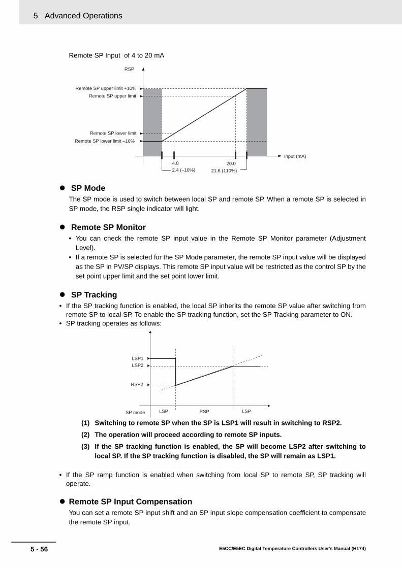
5 Advanced Operations
5 - 56 E5CC/E5EC Digital Temperature Controllers User’s Manual (H174)
Remote SP Input of 4 to 20 mA
SP ModeThe SP mode is used to switch between local SP and remote SP. When a remote SP is selected inSP mode, the RSP single indicator will light.
Remote SP Monitor• You can check the remote SP input value in the Remote SP Monitor parameter (Adjustment
Level).• If a remote SP is selected for the SP Mode parameter, the remote SP input value will be displayed
as the SP in PV/SP displays. This remote SP input value will be restricted as the control SP by theset point upper limit and the set point lower limit.
SP Tracking• If the SP tracking function is enabled, the local SP inherits the remote SP value after switching from
remote SP to local SP. To enable the SP tracking function, set the SP Tracking parameter to ON.• SP tracking operates as follows:
(1) Switching to remote SP when the SP is LSP1 will result in switching to RSP2.
(2) The operation will proceed according to remote SP inputs.
(3) If the SP tracking function is enabled, the SP will become LSP2 after switching tolocal SP. If the SP tracking function is disabled, the SP will remain as LSP1.
• If the SP ramp function is enabled when switching from local SP to remote SP, SP tracking willoperate.
Remote SP Input CompensationYou can set a remote SP input shift and an SP input slope compensation coefficient to compensatethe remote SP input.
Remote SP lower limit
Remote SP upper limit
Remote SP lower limit −10%
Remote SP upper limit +10%
RSP
4.02.4 (−10%) 21.6 (110%)
20.0
Input (mA)
LSP1
LSP2
RSP2
SP mode LSP LSPRSP

5 - 57
5 Advanced Operations
E5CC/E5EC Digital Temperature Controllers User’s Manual (H174)
5-22 Lo
gic O
peratio
ns
5
5-22-1 The Logic O
peration Function (C
X-T
hermo)
5-22 Logic Operations
• The logic operation function logically calculates as 1 or 0 the Controller status (alarms, SP ramp,RUN/STOP, auto/manual, etc.) and the external event input status, and outputs the results to workbits. The work bit status can be output to auxiliary or control outputs, and operating status can beswitched according to the work bit status.
• Work bit logic operation can be set from 1 to 8. Set them to No operation (Always OFF) (the default)when the work bits are not to be used.
• When logic operations are being used, a dot will be displayed between the first two digits on the No. 2display of the Adjustment Level display
Note: The four numeric digits to identify the product code are displayed in the No. 2 display.
Logic operations are set using the CX-Thermo.
Starting Logic OperationsThere are two ways to start logic operations.• Select Logic Operation Editor from the CX-Thermo tree, and click the Start Button.
• Select Logic Operation Editor from the CX-Thermo Options Menu.
5-22-1 The Logic Operation Function (CX-Thermo)
5-22-2 Using Logic Operations
123.4
l.adj
Dot displayed.
Adjustment level display
Adjustment Level

5 Advanced Operations
5 - 58 E5CC/E5EC Digital Temperature Controllers User’s Manual (H174)
Making the SettingsThe following display will appear on the Logic Operation Editor Setting Window. Set each of theparameters.
(1) Displaying the Library Import Dialog Box Logic operation samples for specific cases are set in the library in advance. Examples ofsettings for specific cases are loaded by selecting them from the library list and clicking theOK Button.
Example: Selecting Library 1
(2) Switching Work Bit OperationsSelect the work bit logic operations from the Operation of Work Bit 1 to Operation of WorkBit 8 Tab Pages.

5 - 59
5 Advanced Operations
E5CC/E5EC Digital Temperature Controllers User’s Manual (H174)
5-22 Lo
gic O
peratio
ns
5
5-22-2 Using Logic O
perations
(3) Selecting the Operation TypeFrom one to four operations are supported. If work bits are not to be used, set them to Nooperation (Always OFF) (the default).
• No operation (Always OFF)
• Operation 1
(A and B) or (C and D) When conditions A and B or conditions C and D are satisfied
• Operation 2
(A or C) and (B or D)When condition A or C and condition B or D are satisfied
• Operation 3
A or B or C or DWhen condition A, B, C or D is satisfied
• Operation 4
A and B and C and DWhen conditions A, B, C and D are all satisfied

5 Advanced Operations
5 - 60 E5CC/E5EC Digital Temperature Controllers User’s Manual (H174)
(4) Selecting Input AssignmentsSelect the input assignment for the work bit logic operation from the following settings.
* The event inputs that can be used depend on the Controller model.
Parameter name Setting range
Work Bit 1 Input Assignment A
0. Always OFF
1. Always ON
2. ON for one cycle when power is turned ON
3. Event input 1 (external input)*
4. Event input 2 (external input)*
5. Event input 3 (external input)*6. Event input 4 (external input)*
7. Event input 5 (external input)*
8. Event input 6 (external input)*9. Alarm 1
10. Alarm 2
11. Alarm 312. Alarm 4
13. Control output (heating)
14. Control output (cooling)
15. Input error16. RSP input error
17. HB (heater burnout) alarm
18. HS alarm19. Auto/Manual
20. RUN/STOP
21. RSP/LSP22. Program start
23. AT Execute/Cancel
24. SP ramp operating25. Multi-SP No. switching bit 0
26. Multi-SP No. switching bit 1
27. Multi-SP No. switching bit 228. Program end output
29. Work bit 1
30. Work bit 231. Work bit 3
32. Work bit 4
33. Work bit 534. Work bit 6
35. Work bit 7
36. Work bit 8Work Bit 1 Input Assignment B Same as for work bit 1 input assignment A
Work Bit 1 Input Assignment C Same as for work bit 1 input assignment A
Work Bit 1 Input Assignment D Same as for work bit 1 input assignment Ato to
Work Bit 8 Input Assignment D Same as for work bit 1 input assignment A

5 - 61
5 Advanced Operations
E5CC/E5EC Digital Temperature Controllers User’s Manual (H174)
5-22 Lo
gic O
peratio
ns
5
5-22-2 Using Logic O
perations
(5) Switching between Normally Open and Normally Closed for Inputs A to DClick the condition to switch between normally open and normally closed inputs A to D.
(6) Switching between Normally Open and Normally Closed for Work BitsClick the condition to switch between normally open and normally closed work bits.
(7) Setting ON Delay TimesWhen an input with ON delay turns ON, the output will turn ON after the set delay time haselapsed. The setting range is 0 to 9,999. The default is 0 (disabled).
(8) Setting OFF Delay TimesWhen an input with OFF delay turns OFF, the output will turn OFF after the set delay timehas elapsed. The setting range is 0 to 9,999. The default is 0 (disabled).
(9) Switching ON/OFF Delay Time UnitSelect either seconds or minutes for the ON/OFF delay time unit. The default is seconds.If the Work Bit ∗ Operation Type is set to anything but OFF, the Work Bit ∗ ON Delay andWork Bit ∗ OFF Delay will be displayed in the Adjustment Level and the settings can bechanged with key operations.
(10) Changing Event Input DataSelect the event input conditions from the following setting ranges.
Normally open
Normally closed
Normally open
Normally closed
Parameter name Setting range
Internal event 1
0. Not assigned.
1. Event input 1 (external input)
2. Event input 2 (external input)
3. Event input 3 (external input)
4. Event input 4 (external input)
5. Event input 5 (external input)
6. Event input 6 (external input)
7. Work bit 1
8. Work bit 2
9. Work bit 3
10. Work bit 4
11. Work bit 5
12. Work bit 6
13. Work bit 7
14. Work bit 8
Internal event 2 Same as for Event Input Data 1.
Internal event 3 Same as for Event Input Data 1.
Internal event 4 Same as for Event Input Data 1.
Internal event 5 Same as for Event Input Data 1.
Internal event 6 Same as for Event Input Data 1.

5 Advanced Operations
5 - 62 E5CC/E5EC Digital Temperature Controllers User’s Manual (H174)
Note: The internal event data can be changed from the default setting even if there is no event inputterminal (external input). By changing the default setting, the event input assignmentparameters will be displayed at the Controller display and can be set from the Controller.
(11) Changing the Event Input Assignment FunctionSelect the setting for the internal event assignment.When a work bit is selected as event input data, Communications Write Enable/Disablecannot be assigned to an event input.
(12) Changing Control Output and Auxiliary Output SettingsControl output and auxiliary output assignments can be changed. The items that can bechanged depend on the Controller model. For details, refer to 4-6 Setting OutputSpecifications.Assigning a work bit to either a control output or to an auxiliary output is also considered tobe the same as assigning an alarm. For example, if work bit 1 is set for the Auxiliary Output1 Assignment parameter, then alarms 1 to 4 have been assigned.
(13) Displaying Parameter GuidesA description of the parameters can be displayed.
(14) Displaying the Work Bit Use DestinationsDisplay a list of destinations where the work bits are used.
Operating ProcedureThis procedure uses event input 2 to change to RUN or STOP.Event input 2 ON: RUNEvent input 2 OFF: STOP
1. Select Logic Operation Editor from the CX-Thermo tree, and click the Start Button.
Event 2 Work bit 1
Always OFF
Reverse operation
Always OFF
Always OFF
5 - 63
5 Advanced Operations
E5CC/E5EC Digital Temperature Controllers User’s Manual (H174)
5-22 Lo
gic O
peratio
ns
5
5-22-2 Using Logic O
perations
2. The Logic Operation Editor will be displayed. Confirm that the screen for work bit 1 is displayed, and select Operation 3 from the Operation Type Field.
3. Set the operation by selecting one of the following:Work bit 1 input assignment A = 4: Event input 2 (external input)Work bit 1 input assignment B = 0: Always OFFWork bit 1 input assignment C = 0: Always OFFWork bit 1 input assignment D = 0: Always OFF
4. Invert work bit 1. Click (Normally open) to change it
to (Normally closed).
5. Assign RUN/STOP to event input 2. Set “5: Work bit 1” for the event input data for event input 2, and set “RUN/STOP” for the assignment function.
6. Closing the Logic Operation Editor Dialog BoxClick the Close Button.This completes the procedure for setting parameters using the CX-Thermo. Transfer the settings to the Controller to set the Controller. Refer to CX-Thermo help for the procedure to transfer the settings.

5 Advanced Operations
5 - 64 E5CC/E5EC Digital Temperature Controllers User’s Manual (H174)
Operating ProcedureThis procedure outputs alarm 1 status to auxiliary output 1 during operation (RUN). A library object is used to make the setting.
1. Select Logic Operation Editor from the CX-Thermo tree, and click the Start Button.
2. Click the Import of Library Button.
Alarm 1 RUN/STOPWork bit 1
Always OFF Always OFF

5 - 65
5 Advanced Operations
E5CC/E5EC Digital Temperature Controllers User’s Manual (H174)
5-22 Lo
gic O
peratio
ns
5
5-22-2 Using Logic O
perations
3. Select Library 1 from the library list, and then click the OK Button.Confirm the following settings, and then click the OK Button.Work bit 1 operation type: Operation 1Work bit 1 input assignment A = 7: Alarm 1Work bit 1 input assignment B = 19: Invert for RUN/STOPWork bit 1 input assignment C = 0: Always OFFWork bit 1 input assignment D = 0: Always OFFAuxiliary output 1 = Work bit 1
4. Closing the Logic Operation Editor Dialog BoxClick the Close Button.
This completes the procedure for setting parameters using the CX-Thermo. Transfer the settings to the Controller to set the Controller. Refer to CX-Thermo help for the procedure to transfer the settings.

5 Advanced Operations
5 - 66 E5CC/E5EC Digital Temperature Controllers User’s Manual (H174)

6 - 1E5CC/E5EC Digital Temperature Controllers User’s Manual (H174)
6
6-1 Conventions Used in this Section . . . . . . . . . . . . . . . . . . . . . . . . . . . . . . . . 6-2
6-2 Protect Level . . . . . . . . . . . . . . . . . . . . . . . . . . . . . . . . . . . . . . . . . . . . . . . . . . 6-3
6-3 Operation Level . . . . . . . . . . . . . . . . . . . . . . . . . . . . . . . . . . . . . . . . . . . . . . . 6-7
6-4 Adjustment Level . . . . . . . . . . . . . . . . . . . . . . . . . . . . . . . . . . . . . . . . . . . . . 6-17
6-5 Monitor/Setting Item Level . . . . . . . . . . . . . . . . . . . . . . . . . . . . . . . . . . . . . 6-35
6-6 Manual Control Level . . . . . . . . . . . . . . . . . . . . . . . . . . . . . . . . . . . . . . . . . . 6-36
6-7 Initial Setting Level . . . . . . . . . . . . . . . . . . . . . . . . . . . . . . . . . . . . . . . . . . . 6-38
6-8 Advanced Function Setting Level . . . . . . . . . . . . . . . . . . . . . . . . . . . . . . . . 6-54
6-9 Communications Setting Level . . . . . . . . . . . . . . . . . . . . . . . . . . . . . . . . . . 6-84
Parameters

6 Parameters
6 - 2 E5CC/E5EC Digital Temperature Controllers User’s Manual (H174)
6-1 Conventions Used in this Section
Meanings of Icons Used in this Section
About Related Parameter DisplaysParameters are displayed only when the conditions for use given on the right of the parameterheading are satisfied. Protected parameters are not displayed regardless of the conditions for use,but the settings of these parameters are still valid.
The Order of Parameters in This SectionParameters are described level by level. The first page of each level describes the parameters in the level and the procedure to switchbetween parameters.
AlarmsIt will be specified in this section when alarms are set for the Control Output 1 or 2 Assignmentparameters, or for the Auxiliary Output 1 to 4 Assignment parameters. For example, when alarm 1 isset for the Control Output 1 Assignment parameter, it will be specified that alarm 1 is assigned. Assigning a work bit to either control output 1 or 2 or to auxiliary output 1 to 4 is also considered tobe the same as assigning an alarm. For example, if work bit 1 is set for the Auxiliary Output 1Assignment parameter, then alarms 1 to 4 have been assigned.
Describes the functions of the parameter.
Describes the setting range and default of the parameter.
Used to indicate parameters used only for monitoring.
Describes the parameter settings, such as those for Operation Commands, and procedures.
Used to indicate information on descriptions in which the parameter is used or the names of related parameters.
Function
Setting
Monitor
Operation
SeeSee
at AT Execute/CancelThe E5CC/E5EC must be in operation, and control must be 2-PID control.
Displayed symbol Parameter name Conditions for use

6 - 3
6 Parameters
E5CC/E5EC Digital Temperature Controllers User’s Manual (H174)
6-2 Pro
tect Level
6
6-2 Protect Level
Four levels of protection are provided on the E5CC/E5EC, operation/adjustment protect, initial set-ting/communications protect, setting change protect, and PF key protect. These protect levels preventunwanted operation of the keys on the front panel in varying degrees.
The password to move to the Protect Level is entered for this parameter.
pmoV Move to Protect LevelThe Password to Move to Protect Level password must not be set to 0.
• If the correct password is entered, the Operation/Adjustment Protect parameter isdisplayed.
Related ParametersPassword to Move to Protect Level (Protect Level): page 6-6
25
0
oapt
0
prlp
on
pmsk
off
pfpt
off
wtpt
1
icpt
0
pmov
off
chgp
Parameter Mask EnableDisplayed only when a parameter mask is set.
M
M
M
M
M
M
M
M
0
Parameters that are protected will not be displayed and their settings cannot be changed.
Control in Progress
Operation Level
Adjustment Level
Protect Level
Power ON
Press the O Key for less than 1 s.
Press the O + M Keys for at least 1 s.
Press the O + M keys; display will flash.
Press the O + M Keys for at least 3 s.
Protect Level
PageMove to Protect LevelDisplayed only when a password is set.
Operation/Adjustment Protect
Initial Setting/Communications Protect
Setting Change Protect
Changed Parameters Only
Password to Move to Protect Level
PF Key Protect
6-3
6-4
6-4
6-5
6-5
6-5
6-6
6-6
To move from the Operation Level to the Protect Level, press O and M Keys for three seconds (see note) or more.
* The time taken to move to the Protect Level can be adjusted by changing the Move to Protect Level Time pa-rameter setting.
Function
SeeSee

6 Parameters
6 - 4 E5CC/E5EC Digital Temperature Controllers User’s Manual (H174)
These parameters specify the range of parameters to be protected. Shaded settings are the defaults.
oapt Operation/Adjustment Protect
icptInitial Setting/Communications Protect
Operation/Adjustment ProtectThe following table shows the relationship between set values and the range ofprotection.
• Parameters are not protected when the set value is set to 0.
Initial Setting/Communications ProtectThis protect level restricts movement to the Initial Setting Level, Communications SettingLevel, and Advanced Function Setting Level.
Function
Setting
LevelSet value
0 1 2 3
Operation Level
PV Can be dis-played
Can be dis-played
Can be dis-played
Can be dis-played
PV/SP Can be dis-played and changed
Can be dis-played and changed
Can be dis-played and changed
Can be dis-played
Others Can be dis-played and changed
Can be dis-played and changed
Cannot be displayed and moving to other lev-els is not possible
Cannot be displayed and moving to other lev-els is not possible
Adjustment Level Can be dis-played and changed
Cannot be displayed and moving to other lev-els is not possible
Cannot be displayed and moving to other lev-els is not possible
Cannot be displayed and moving to other lev-els is not possible
Set value Initial setting levelCommunications
setting levelAdvanced function
setting level0 Possible to reach Possible to reach Possible to reach
1 Possible to reach Possible to reach Not possible to reach
2 Not possible to reach Not possible to reach Not possible to reach

6 - 5
6 Parameters
E5CC/E5EC Digital Temperature Controllers User’s Manual (H174)
6-2 Pro
tect Level
6
Changes to settings using key operations are restricted. The shaded cell indicates the default.
wtpt Setting Change ProtectThe Event Input Assignment 1 to Event Input Assignment 6 parameters must not be set to enable/disable setting changes.
Change Setting ProtectThis parameter is not displayed if the Event Input Assignment 1 to Event InputAssignment 6 parameters are set to enable/disable setting changes.
• The all protect indication ( ) will light when setting is ON.
pfpt PF Key Protect
PF Key ProtectThis parameter enables and disables PF Key operation.
* The shaded cell indicates the default.
chgp Changed Parameters Only
This parameter allows you to display only the parameters that have been changed fromtheir default settings.
Function
Setting
Set value DescriptionOFF Settings can be changed using key operations.
ON Settings cannot be changed using key operations. (The protect level settings, however, can be changed.)
Function
Setting
Set value DescriptionOFF PF Key enabled
ON PF Key disabled (Operation as a function key is prohibited.)
Function
Setting
Setting range Defaulton: Enabled, off: Disabled off

6 Parameters
6 - 6 E5CC/E5EC Digital Temperature Controllers User’s Manual (H174)
* A parameter mask can be used to hide the displays of parameters that are not needed. The parameter maskfunction is provided by the Setup Tool. Setup Tool: CX-Thermo (EST2-2C-MV4)
This parameter is used to set the password to move to the Protect Level.
Precautions for Correct Use
Protection cannot be cleared or changed without the password. Be careful not to forget it. If youforget the password, contact your OMRON sales representative.
pmsk Parameter Mask EnableThis parameter is displayed only when a parameter mask has been set from the Setup Tool.
• This parameter turns the parameter mask function ON and OFF.
prlp Password to Move to Protect Level
• To prevent setting the password incorrectly, the U and O Keys or D and O Keys mustbe pressed simultaneously to set the password.
Set this parameter to 0 when no password is to be set.
Related ParametersMove to Protect Level (Protect Level): Page 6-3
Function
Setting
Setting range Defaulton: Enabled, off: Disabled on
Function
Setting
Setting range Default−1999 to 9999 0
SeeSee

6 - 7
6 Parameters
E5CC/E5EC Digital Temperature Controllers User’s Manual (H174)
6-3 Op
eration
Level
6
6-3 Operation Level
Display this level to perform control operations on the E5CC/E5EC. You can set alarm values, monitorthe manipulated variable, and perform other operations in this level.
This level is displayed immediately after the power is turned ON.
Control in progress
Control stopped
Control stops.
Power ON
Press the O Key for less than 1 s.
Press the O Key for at least 1 s; display will flash.
Press the O Key for at least 3 s.
Press the O Key for less than 1 s.
25
00
c-o
a-m
0
sktr
00
ct2
00
ct1
0
m-sp
rset
prst
run
r-s
0
sp-m
00
o
00
lcr1
00
lcr2
0
25
0
al1h
0
al2h
0
al3h
0
al1l
0
al2l
0
al3l
0
al-1
0
al-2
0
al-3
0
25
0.0
Rrsp
M
M
M
M
M
M
M
M
M
M
M
M
M
M
M
M
M
M
M
M
M
M
0
al4h
0
al4l
0
al-4
M
M
M
M
M
M
Operation Level
Adjustment Level
Initial Setting LevelCommuni-
cations Setting Level
Operation Level
Page PageProcess Value/Set Point 1
Process Value/Set Point 2
Auto/Manual Switch
Multi-SP Set Point Selection
Remote SP Monitor
Set Point During SP Ramp
Heater Current 1 Value Monitor
Heater Current 2 Value Monitor
Leakage Current 1 Monitor
Leakage Current 2 Monitor
Program Start
Soak Time Remain
RUN/STOP
Alarm Value 1
Alarm Value Upper Limit 1
Alarm Value Lower Limit 1
Alarm Value 2
Alarm Value Upper Limit 2
Alarm Value Lower Limit 2
Alarm Value 3
Alarm Value Upper Limit 3
Alarm Value Lower Limit 3
MV Monitor (Heating)
MV Monitor (Cooling)
Alarm Value 4
Alarm Value Upper Limit 4
Alarm Value Lower Limit 4
Press the O Key for at least 1 s.
6-8
6-8
6-9
6-9
6-9
6-10
6-10
6-11
6-11
6-12
6-13
6-12
6-13
6-14
6-15
6-15
6-14
6-15
6-15
6-15
6-15
6-14
6-15
6-14
6-15
6-16
6-16

6 Parameters
6 - 8 E5CC/E5EC Digital Temperature Controllers User’s Manual (H174)
Process Value/Set Point 1 PV/SP No. 1 Display Selection must not be set to 0.
Process Value/Set Point 2 PV/SP No. 2 Display Selection must not be set to 0.
The following table shows the contents of the No. 1, 2, and 3 displays, according to the set-ting of the PV/SP Display Selection parameter. (Only the E5EC has a No. 3 display.)
*1 The set value of the Alarm Value 1 parameter is displayed even if it is not valid due to the settingof the Alarm 1 Type parameter.
For a temperature input, the decimal point position depends on the currently selected sen-sor, and for an analog input it depends on the Decimal Point parameter setting.
PV/SP Display Selections
Related ParametersPV/SP Display Selection (Advanced Function Setting Level): Page 6-81
Function
Setting
Set value No. 1 display No. 2 display No. 3 display (E5EC only)0 Nothing is displayed. Nothing is displayed. Nothing is displayed.
1 Process value Set point Nothing is displayed.
2 Process value Nothing is displayed. Nothing is displayed.3 Set point SP (character display) Nothing is displayed.
4 Process value Set point Manipulated value
5 Process value Set point Multi-SP No.6 Process value Set point Soak time remain
7 Process value Set point Internal set point (ramp SP)
8 Process value Set point Alarm value 1*1
Monitor range UnitProcess value Temperature input: The specified range for the specified sensor.
Analog input: Scaling lower limit −5% FS to Scaling upper limit +5% FS
EU
Setting range UnitSet point SP lower limit to SP upper limit EU
Parameter DefaultPV/SP No. 1 Display Selection 4PV/SP No. 2 Display Selection 0
SeeSee

6 - 9
6 Parameters
E5CC/E5EC Digital Temperature Controllers User’s Manual (H174)
6-3 Op
eration
Level
6
a-m Auto/Manual Switch
The Event Input Assignment 1 to Event Input Assignment 6 parameters must not be set to Auto/ Manual and the Auto/Manual Select Addition parameter must be set to ON. The control must be set to 2-PID control.
• This parameter switches the Controller between automatic and manual modes.• If the O Key is pressed for at least 3 seconds when the Auto/Manual Switch parameter is
displayed, the manual mode will be entered and the manual control level will be displayed. • This parameter will not be displayed if an event input is set to "MANU" (auto/manual).
Related ParametersPID ON/OFF (Initial Setting Level): Page 6-41Auto/Manual Select Addition (Advanced Function Setting Level): Page 6-67
m-spMulti-SP Set Point Selection(Set Points 0 to 7)
The Number of Multi-SP Points parameter must not be set to OFF and the Event Input Assignment 1 to Event Input Assignment 6 parameters must not be set to “Multi-SP No. switching bit 0” to “Multi-SP No. switching bit 2.”
To use the multi-SP function, preset the eight set points (SP 0 to 7) in the Adjustment Level,and then switch the set point either by operating the keys or by using external input signals(event inputs). This parameter is used to select set points 0 to 7.
rsp Remote SP MonitorThe ST parameter must be set to OFF.The Remote SP Enable parameter must be set to ON.
This parameter is used to monitor the remote SP.
Related ParametersSP Mode (Adjustment Level): Page 6-20Remote SP Enable (Advanced Function Setting Level): Page 6-75Remote SP Upper Limit (Advanced Function Setting Level): Page 6-76Remote SP Lower Limit (Advanced Function Setting Level): Page 6-76
Operation
SeeSee
Function
MonitorMonitor range Unit
Remote SP lower limit −10% to Remote SP upper limit +10% EU
SeeSee

6 Parameters
6 - 10 E5CC/E5EC Digital Temperature Controllers User’s Manual (H174)
This parameter monitors the set point during SP ramp operation.
This parameter measures the heater current from the CT input used for detecting heater burnout.
sp-m Set Point During SP Ramp
The SP Ramp Set Value parameter must not be set to OFF and the SP Ramp Fall Value parameter must not be set to SAME or OFF. The ST parameter must be set to OFF.
A ramp is used to restrict the change width of the set point as a rate of change. This parameter is displayed when a set value is input for the SP Ramp Set Value parameter(Adjustment Level). When not in ramp operation, the set point will be the same as the one displayed for the Pro-cess Value/Set Point parameter.
Related ParametersProcess Value/Set Point (Operation Level): Page 6-8SP Ramp Set Value (Adjustment Level): Page 6-32SP Ramp Fall Value (Adjustment Level): Page 6-32Set Point Upper Limit (Initial Setting Level): Page 6-41Set Point Lower Limit (Initial Setting Level): Page 6-41
ct1 Heater Current 1 Value MonitorHB and HS alarms must be supported. The HB ON/OFF parameter must be set to ON.
This parameter measures and displays the heater current value. • Heater burnout is not detected if the ON time for the control output for heating is 100 ms
or less (30 ms or less if the control period is 0.1 or 0.2 s).
• ffff is displayed when 55.0 A is exceeded. • If an alarm is output for the Heater Burnout Detection 1 parameter, the No. 1 display will
flash the Heater Current 1 Value Monitor parameter.
Related ParametersHeater Burnout Detection 1 (Adjustment Level): Page 6-21Heater Burnout Detection 2 (Adjustment Level): Page 6-22HB ON/OFF (Advanced Function Setting Level): Page 6-58Error Display ct1: Page A-12
Function
Monitor
Monitor range UnitSP: SP lower limit to SP upper limit EU
SeeSee
Function
Monitor
Monitor range Unit0.0 to 55.0 A
SeeSee

6 - 11
6 Parameters
E5CC/E5EC Digital Temperature Controllers User’s Manual (H174)
6-3 Op
eration
Level
6
This parameter measures the heater current from the CT input used for detecting heater burnout.
This parameter measures the heater current from the CT input used for detecting SSR short-circuits.
ct2 Heater Current 2 Value MonitorHB and HS alarms must be supported (two CTs).The HB ON/OFF parameter must be set to ON.
This parameter measures and displays the heater current value. • Heater burnout is not detected if the ON time for the control output for heating is 100 ms
or less (30 ms or less if the control period is 0.1 or 0.2 s).
• ffff is displayed when 55.0 A is exceeded. • If an alarm is output for the Heater Burnout Detection 2 parameter, the No. 1 display will
flash the Heater Current 2 Value Monitor parameter.
Related ParametersHeater Burnout Detection 1 (Adjustment Level): Page 6-21Heater Burnout Detection 2 (Adjustment Level): Page 6-22HB ON/OFF (Advanced Function Setting Level): Page 6-58Error Display ct2: Page A-12
lcr1 Leakage Current 1 MonitorHB and HS alarms must be supported.The HS Alarm Use parameter must be set to ON.
The heater current is measured and the leakage current 1 monitor is displayed. • The HS alarm is not detected if the OFF time for the control output for heating is 100 ms
or less (35 ms or less if the control period is 0.1 or 0.2 s).
• ffff is displayed when 55.0 A is exceeded. • If an alarm is output for the HS Alarm 1 parameter, the No. 1 display will flash the
Leakage Current 1 Monitor parameter.
Related ParametersHS Alarm 1 (Adjustment Level): Page 6-23HS Alarm 2 (Adjustment Level): Page 6-24HS Alarm Use (Advanced Function Setting Level): Page 6-68Error Display lcr1: Page A-12
Function
Monitor
Monitor range Unit0.0 to 55.0 A
SeeSee
Function
Monitor
Monitor range Unit0.0 to 55.0 A
SeeSee
6 Parameters
6 - 12 E5CC/E5EC Digital Temperature Controllers User’s Manual (H174)
This parameter measures the heater current from the CT input used for detecting SSR short-circuits.
This parameter starts and stops the simple program function.
lcr2 Leakage Current 2 MonitorHB and HS alarms must be supported (two CTs).The HS Alarm Use parameter must be set to ON.
This parameter measures and displays the heater current value. • The HS alarm is not detected if the OFF time for the control output for heating is 100 ms
or less (35 ms or less if the control period is 0.1 or 0.2 s).
• ffff is displayed when 55.0 A is exceeded.• If an alarm is output for the HS Alarm 2 parameter, the No. 1 display will flash the
Leakage Current 2 Monitor parameter.
Related ParametersHS Alarm 1 (Adjustment Level): Page 6-23HS Alarm 2 (Adjustment Level): Page 6-24HS Alarm Use (Advanced Function Setting Level): Page 6-68Error Display lcr2: Page A-12
prst Program StartThe Program Pattern parameter must not be set to OFF.
• The RUN/STOP status will automatically switch to RUN when this parameter is set toSTRT.
• The simple program will stop when this parameter is set to RSET.• This parameter will function as a monitor display for the start/stop status of the simple
program if an event input is selected to start the simple program.
Related ParametersSoak Time Remain (Operation Level): Page 6-13RUN/STOP (Operation Level): Page 6-13Soak Time (Adjustment Level): Page 6-30Wait Band (Adjustment Level): Page 6-30Program Pattern (Initial Setting Level): Page 6-43Soak Time Unit (Advanced Function Setting Level): Page 6-74
Function
Monitor
Monitor range Unit0.0 to 55.0 A
SeeSee
Function
Operation
Setting range DefaultRSET Stops the simpler program. rset
STRT Starts the simpler program.
SeeSee

6 - 13
6 Parameters
E5CC/E5EC Digital Temperature Controllers User’s Manual (H174)
6-3 Op
eration
Level
6
This parameter starts and stops the control operation.
sktr Soak Time RemainThe Program Pattern parameter must not be set to OFF.
• This parameter measures and displays the remaining time of the soak time for the simpleprogram function.
Related ParametersProgram Start (Operation Level): Page 6-12Soak Time (Adjustment Level): Page 6-30Wait Band (Adjustment Level): Page 6-30Program Pattern (Initial Setting Level): Page 6-43Soak Time Unit (Advanced Function Setting Level): Page 6-74
r-s RUN/STOPThe Event Input Assignment 1 to 6 parameters must not be set to RUN/STOP.
When run (RUN) is selected, control is started. When stop (STOP) is selected, control isstopped. The STOP indicator will light when control is stopped.
The default is run.
This parameter will not be displayed if an event input is set to “RUN/STOP.”
Function
Monitor
Monitor range Unit0 to 9999 min or h
SeeSee
Operation
SeeSee

6 Parameters
6 - 14 E5CC/E5EC Digital Temperature Controllers User’s Manual (H174)
This parameter is set to one of the input values "X" in the alarm type list. (Page 3-16)
al-1 Alarm Value 1
Alarm 1 to alarm 4 must be assigned.The Alarm 1 to 4 Type parameters must not be set to 0, 1, 4, 5, or 12.
al-2 Alarm Value 2
al-3 Alarm Value 3
al-4 Alarm Value 4
• These parameters set the alarm values for alarms 1 to 4.• During temperature input, the decimal point position depends on the currently selected
sensor, and during analog input it depends on the Decimal Point parameter setting.
Alarms Other Than an MV Alarm
MV Alarms
Related ParametersInput Type (Initial Setting Level): Page 6-39Scaling Upper Limit (Initial Setting Level): Page 6-40Scaling Lower Limit (Initial Setting Level): Page 6-40Decimal Point (Initial Setting Level): Page 6-40Alarm 1 to 4 Type (Initial Setting Level): Page 6-44Alarm 1 to 4 Hysteresis (Initial Setting Level): Page 6-48Standby Sequence Reset (Advanced Function Setting Level): Page 6-57Auxiliary Output 1 to 4 Open in Alarm (Advanced Function Setting Level): Page 6-58Alarm 1 to 4 Latch (Advanced Function Setting Level): Page 6-63
Function
Setting range Unit Default−1999 to 9999 EU 0
Setting range Unit Default−199.9 to 999.9 % 0.0
SeeSee

6 - 15
6 Parameters
E5CC/E5EC Digital Temperature Controllers User’s Manual (H174)
6-3 Op
eration
Level
6
These parameters individually set the alarm value upper and lower limits when a mode for setting theupper and lower limits is selected for the Alarm 1 to 4 Type parameter (Initial Setting Level).
al1h Alarm Value Upper Limit 1
Alarm 1 to alarm 4 must be assigned.The Alarm 1 to 4 Type parameter must be set to 1, 4, or 5.
al2h Alarm Value Upper Limit 2
al3h Alarm Value Upper Limit 3
al4h Alarm Value Upper Limit 4
al1l Alarm Value Lower Limit 1
al2l Alarm Value Lower Limit 2
al3l Alarm Value Lower Limit 3
al4l Alarm Value Lower Limit 4
• These parameters set the upper and lower limits for alarms 1 to 4.• During temperature input, the decimal point position depends on the currently selected
sensor, and during analog input it depends on the Decimal Point parameter setting.
Related ParametersInput Type (Initial Setting Level): Page 6-39Scaling Upper Limit (Initial Setting Level): Page 6-40Scaling Lower Limit (Initial Setting Level): Page 6-40Decimal Point (Initial Setting Level): Page 6-40Alarm 1 to 4 Type (Initial Setting Level): Page 6-44Alarm 1 to 4 Hysteresis (Initial Setting Level): Page 6-48Standby Sequence Reset (Advanced Function Setting Level): Page 6-57Auxiliary Output 1 to 4 Open in Alarm (Advanced Function Setting Level): Page 6-58Alarm 1 to 4 Latch (Advanced Function Setting Level): Page 6-63
Function
Setting
Setting range Unit Default−1999 to 9999 EU 0
SeeSee

6 Parameters
6 - 16 E5CC/E5EC Digital Temperature Controllers User’s Manual (H174)
This parameter is used to monitor the manipulated variable for the heating control output during opera-tion.
This parameter is used to monitor the manipulated variable for the cooling control output during opera-tion.
o MV Monitor (Heating) The MV Display parameter must be set to ON.
• During standard control, the manipulated variable is monitored. During heating/coolingcontrol, the manipulated variables on the control output (heating) is monitored.
• The default is OFF and the manipulated variable is not displayed.
Related ParametersMV Display (Advanced Function Setting Level): Page 6-62
c-o MV Monitor (Cooling)The control system must be set to heating/cooling control.The MV Display parameter must be set to ON.
• During heating/cooling control, the manipulated variable on the control output (cooling) ismonitored.
• The default is OFF and the manipulated variable is not displayed.
Related ParametersStandard or Heating/Cooling (Initial Setting Level): Page 6-42MV Display (Advanced Function Setting Level): Page 6-62
Function
Monitor
Control Monitor range UnitStandard −5.0 to 105.0 %
Heating/cooling 0.0 to 105.0 %
SeeSee
Function
Monitor
Control Monitor range UnitHeating/cooling 0.0 to 105.0 %
SeeSee

6 - 17
6 Parameters
E5CC/E5EC Digital Temperature Controllers User’s Manual (H174)
6-4 Ad
justm
ent L
evel
6
6-4 Adjustment Level
This level is for executing AT (auto-tuning) and other operations, and for set control parameters.This level provides the basic Controller parameters for PID control (proportional band, integral time,derivative time) and heating/cooling control.
To move to the Adjustment Level from the Operation Level,press the O Key once.• The set points 0 to 7 in the Adjustment Level are the set
values for switching the set point during multi-SP input.• The following items are displayed for Controllers with CT
Inputs: Heater current monitors, Leakage current monitors,HB alarm detection, and HS alarm detection.
• Adjustment level parameters can be changed after settingthe Operation/Adjustment Protect parameter to 0. Displaysand changing levels are not possible if theOperation/Adjustment Protect parameter is set to 1 to 3.Protection is set in the Protect Level.
Control in progress
Operation Level
Adjustment Level
Power ON
Press the O Key for less than 1 s.

6 Parameters
6 - 18 E5CC/E5EC Digital Temperature Controllers User’s Manual (H174)
M
1234
l.adj
M
off
at
M
off
cmwt
SP Mode
M
lsp
spmd
M
0.0
ct1
M
0.0
hb1
M
0.0
ct2
M
0.0
hb2
M
0.0
lcr1
M
50.0
hs1
M
0.0
lcr2
M
50.0
hs2
M
0
sp-0
M
0
sp-1
M
0
sp-3
M
0
sp-4
M
0
sp-5
M
0
sp-6
M
0
sp-7
Process Value Input Shift
M
0.0
ins
Process Value Slope Coefficient
M
1.000
inrt
Remote SP Input Shift
M
0.0
Rrss
Remote SP Input Slope Coefficient
M
1.000
Rrsrt
M
8.0
p
M
233
i
M
40
d
Proportional Band (Cooling)
M
8.0
c-p
Integral Time (Cooling)
M
M
233
c-i
M
50.0
of-r
M
1.0
hys
M
1.0
chys
M
1
soak
M
off
wt-b
M
0.0
mv-s
M
0.0
mv-e
M
off
sprt
SP Ramp Fall Value
M
same
sprl
M
100.0
ol-h
M
0.0
ol-l
M
Work Bit 1 OFF Delay
w1of
M
Work Bit 1 ON Delay
w1on
M
0.0
orl
0.0
sqrp
M
M
w2of
M
w3on
M
w3of
M
w4on
M
w4of
M
w5on
M
w5of
M
w6on
M
w6of
M
w7on
M
w7of
M
M
w8on
w8of
Derivative Time (Cooling)
40
c-d
0
sp-20.0
c-db Work Bit 2 ON Delay
M
w2on
M
Adjustment LevelPage
Adjustment Level Display
AT Execute/Cancel
Communications Writing
Heater Current 1 Value Monitor
Heater Current 2 Value Monitor
Leakage Current 1 Monitor
Leakage Current 2 Monitor
Heater Burnout Detection 1
Heater Burnout Detection 2
HS Alarm 1
HS Alarm 2
SP 0
SP 1
SP 2
Proportional Band
Integral Time
Derivative Time
Dead Band
Manual Reset Value
Hysteresis (Heating)
Hysteresis (Cooling)
Soak Time
Wait Band
MV at Stop
MV at PV Error
SP Ramp Set Value
MV Upper Limit
MV Lower Limit
MV Change Rate Limit
Page Page Page
SP 3
SP 4
SP 5
SP 6
SP 7
Extraction of Square Root Low-cut Point
Work Bit 2 OFF Delay
Work Bit 3 ON Delay
Work Bit 3 OFF Delay
Work Bit 4 ON Delay
Work Bit 4 OFF Delay
Work Bit 5 ON Delay
Work Bit 5 OFF Delay
Work Bit 6 ON Delay
Work Bit 6 OFF Delay
Work Bit 7 ON Delay
Work Bit 7 OFF Delay
Work Bit 8 ON Delay
Work Bit 8 OFF Delay
6-19
6-19
6-20
6-20
6-21
6-21
6-22
6-22
6-23
6-23
6-24
6-24
6-25
6-25
6-25
6-25
6-25
6-25
6-25
6-26
6-26
6-26
6-27
6-27
6-27
6-27
6-28
6-28
6-28
6-28
6-25
6-29
6-29
6-30
6-30
6-31
6-31
6-32
6-32
6-32
6-32
6-33
6-33
6-34
6-34
6-34
6-29
6-34
6-34
6-34
6-34
6-34
6-34
6-34
6-34
6-34
6-34
6-34
6-34
6-34

6 - 19
6 Parameters
E5CC/E5EC Digital Temperature Controllers User’s Manual (H174)
6-4 Ad
justm
ent L
evel
6
This parameter is displayed after moving to the Adjustment Level. The four numeric digits to identify theproduct code are displayed in the No. 2 display.When a logic operation is set, a period "." will be displayed on the No. 2. display.
This parameter executes auto-tuning (AT).
l.adj Adjustment Level Display
• This parameter indicates that the Adjustment Level has been entered.(The Adjustment Level parameter will not be displayed again even if the M Key is pressed in the Adjustment Level to scroll through the parameters.)
at AT Execute/Cancel
The E5CC/E5EC must be in operation, and control must be 2-PID control. Event Input Assignment 1 to Event Input Assignments 6 parameters must be other than 100% or 40% AT Execute/Cancel.
• The MV is forcibly increased and decreased around the set point to find thecharacteristics of the control object. From the results, the PID constants are automaticallyset in the Proportional Band (P), Integral Time (I), and Derivative Time (D) parameters.
• Both 100% AT and 40% AT are supported for AT.Only 100% AT can be executed for heating and cooling control.
• For heating/cooling control, select the tuning methods that is suitable for the coolingcontrol characteristics in the Heating/Cooling Tuning Method parameter.
• If autotuning is performed with the default settings, the cooling PID constants (i.e.,Proportional Band (Cooling), Integral Time (Cooling), and Derivative Time (Cooling)parameters) have the same values as the heating PID constants.
• This parameter will not be displayed when either 100% or 40% AT execute/cancel is set tobe executed using an event input.
• This parameter is normally off. Press the U Key and select at-2 or at-1 to executeAT. AT cannot be executed when control is stopped or during ON/OFF control.
• The TUNE indicator will light during autotuning.• When AT execution ends, the parameter setting automatically returns to off.
Related ParametersProportional Band (Adjustment Level): Page 6-27Integral Time (Adjustment Level): Page 6-27Derivative Time (Adjustment Level): Page 6-27Proportional Band (Cooling) (Adjustment Level): Page 6-28Integral Time (Cooling) (Adjustment Level): Page 6-28Derivative Time (Cooling) (Adjustment Level): Page 6-28PID ON/OFF (Initial Setting Level): Page 6-41Heating/Cooling Tuning Method (Advanced Function Setting Level): Page 6-78
Function
Function
Operation
Setting rage DefaultOFF:AT-2:AT-1:
AT Cancel100%AT Execute40%AT Execute
OFF
SeeSee

6 Parameters
6 - 20 E5CC/E5EC Digital Temperature Controllers User’s Manual (H174)
cmwt Communications Writing
Communications must be supported. The Event Input Assignment 1 to Event Input Assignment 6 parameters must not be set to enable/disable communications writing.
• This parameter enables/disables writing of parameters to the E5CC/E5EC from the host(personal computer) using communications.
• This parameter is not displayed if the Event Input Assignment 1 to Event InputAssignment 6 parameters are set to enable/disable communications writing.
Related ParametersCommunications Unit No. (Communications Setting Level): Page 6-84Communications Baud Rate (Communications Setting Level): Page 6-84Communications Data Length (Communications Setting Level): Page 6-84Communications Parity (Communications Setting Level): Page 6-84Communications Stop Bits (Communications Setting Level): Page 6-84
spmd SP Mode
The ST parameter must be set to OFF, and the Remote SP Enable parameter must be set to ON.The Event Input Assignment 1 to Event Input Assignment 6 parameters must not be set to change the SP mode.
This parameter sets the SP mode. In Local SP Mode, the local SP that is set inside the Dig-ital Controller is used as the SP. In Remote SP Mode, the remote SP that is specified withan external signal (e.g., 4 to 20 mA) is used as the SP.
Related ParametersRemote SP Enable (Advanced Function Setting Level): Page 6-75
Function
Setting
Setting rage DefaultON:OFF:
Writing enabledWriting disabled
OFF
SeeSee
Function
Setting range DefaultLSP: Local SP and RSP: Remote SP LSP
SeeSee

6 - 21
6 Parameters
E5CC/E5EC Digital Temperature Controllers User’s Manual (H174)
6-4 Ad
justm
ent L
evel
6
This parameter measures the heater current from the CT input used for detecting heater burnout.
This parameter sets the current for the heater burnout alarm to be output.
ct1 Heater Current 1 Value MonitorHB and HS alarms must be supported.The HB ON/OFF parameter must be set to ON.
This parameter measures and displays the heater current value.• Heater burnout is not detected if the ON time for the control output for heating is 100 ms
or less (30 ms or less if the control period is 0.1 or 0.2 s).
• ffff is displayed when 55.0 A is exceeded. • If an alarm is output for the Heater Burnout Detection 1 parameter, the No. 1 display will
flash the Heater Current 1 Value Monitor parameter.
Related ParametersHeater Burnout Detection 1 (Adjustment Level): Page 6-21Heater Burnout Detection 2 (Adjustment Level): Page 6-22HB ON/OFF (Advanced Function Setting Level): Page 6-58Error Displays ct1: Page A-12
hb1 Heater Burnout Detection 1HB and HS alarms must be supported.The HB ON/OFF parameter must be set to ON.
• The heater burnout alarm is output when the heater current value falls below the settingof this parameter.
• When the set value is 0.0, the heater burnout alarm output is turned OFF. When the setvalue is 50.0, the heater burnout alarm output is turned ON.
Related ParametersHeater Current 1 Value Monitor (Adjustment Level): Page 6-21Heater Burnout Detection (Advanced Function Setting Level): Page 6-58Heater Burnout Latch (Advanced Function Setting Level): Page 6-59Heater Burnout Hysteresis (Advanced Function Setting Level): Page 6-59
Function
Monitor
Monitor range Unit0.0 to 55.0 A
SeeSee
Function
Setting
Setting range Unit Default0.0 to 50.0 A 0.0
SeeSee

6 Parameters
6 - 22 E5CC/E5EC Digital Temperature Controllers User’s Manual (H174)
This parameter measures the heater current from the CT input used for detecting heater burnout.
This parameter sets the current for the heater burnout alarm to be output.
ct2 Heater Current 2 Value MonitorHB and HS alarms must be supported (two CTs).The HB ON/OFF parameter must be set to ON.
This parameter measures and displays the heater current value.• Heater burnout is not detected if the ON time for the control output for heating is 100 ms
or less (30 ms or less if the control period is 0.1 or 0.2 s).
• ffff is displayed when 55.0 A is exceeded.• If an alarm is output for the Heater Burnout Detection 2 parameter, the No. 1 display will
flash the Heater Current 2 Value Monitor parameter.
Related ParametersHeater Burnout Detection 1 (Adjustment Level): Page 6-21Heater Burnout Detection 2 (Adjustment Level): Page 6-22Error Displays ct2: Page A-12
hb2 Heater Burnout Detection 2HB and HS alarms must be supported (two CTs).The HB ON/OFF parameter must be set to ON.
• The heater burnout alarm is output when the heater current value falls below the settingof this parameter.
• When the set value is 0.0, the heater burnout alarm output is turned OFF. When the setvalue is 50.0, the heater burnout alarm output is turned ON.
Related ParametersHeater Current 2 Value Monitor (Adjustment Level): Page 6-22HB ON/OFF (Advanced Function Setting Level): Page 6-58Heater Burnout Latch (Advanced Function Setting Level): Page 6-59Heater Burnout Hysteresis (Advanced Function Setting Level): Page 6-59
Function
Monitor
Monitor range Unit0.0 to 55.0 A
SeeSee
Function
Setting
Setting range Unit Default0.0 to 50.0 A 0.0
SeeSee

6 - 23
6 Parameters
E5CC/E5EC Digital Temperature Controllers User’s Manual (H174)
6-4 Ad
justm
ent L
evel
6
This parameter measures the heater current from the CT input used for detecting SSR short-circuits.
This parameter sets the current for the HS alarm to be output.
lcr1 Leakage Current 1 MonitorHB and HS alarms must be supported.The HS Alarm Use parameter must be set to ON.
This parameter measures and displays the heater current when the heater is OFF. • The HS alarm is not detected if the OFF time for the control output for heating is 100 ms
or less (35 ms or less if the control period is 0.1 or 0.2 s).
• ffff is displayed when 55.0 A is exceeded. • If an alarm is output for the HS Alarm 1 parameter, the No. 1 display will flash the
Leakage Current 1 Monitor parameter.
Related ParametersHS Alarm 1 (Adjustment Level): Page 6-23HS Alarm 2 (Adjustment Level): Page 6-24HS Alarm Use (Advanced Function Setting Level): Page 6-68Error Displays lcr1: Page A-12
hs1 HS Alarm 1HB and HS alarms must be supported.The HS Alarm Use parameter must be set to ON.
• An HS alarm is output when the leakage current value exceeds the setting of thisparameter.
• When the set value is 50.0, the HS alarm output is turned OFF. When the set value is 0.0,the HS alarm output is turned ON.
Related ParametersLeakage Current 1 Monitor (Adjustment Level): Page 6-23HS Alarm (Advanced Function Setting Level): Page 6-68HS Alarm Latch (Advanced Function Setting Level): Page 6-69HS Alarm Hysteresis (Advanced Function Setting Level): Page 6-69
Function
Monitor
Monitor range Unit0.0 to 55.0 A
SeeSee
Function
Setting
Setting range Unit Default0.0 to 50.0 A 50.0
SeeSee

6 Parameters
6 - 24 E5CC/E5EC Digital Temperature Controllers User’s Manual (H174)
This parameter measures the heater current from the CT input used for detecting SSR short-circuits.
This parameter sets the current for the HS alarm to be output.
lcr2 Leakage Current 2 MonitorHB and HS alarms must be supported (two CTs).The HS Alarm Use parameter must be set to ON.
This parameter measures and displays the heater current when the heater is OFF.• The HS alarm is not detected if the OFF time for the control output for heating is 100 ms
or less (35 ms or less if the control period is 0.1 or 0.2 s).
• ffff is displayed when 55.0 A is exceeded.• If an alarm is output for the HS Alarm 2 parameter, the No. 1 display will flash the
Leakage Current 2 Monitor parameter.
Related ParametersHS Alarm 1 (Adjustment Level): Page 6-23HS Alarm 2 (Adjustment Level): Page 6-24HS Alarm Use (Advanced Function Setting Level): Page 6-68Error Displays lcr2: Page A-12
hs2 HS Alarm 2HB and HS alarms must be supported (two CTs).The HS Alarm Use parameter must be set to ON.
• An HS alarm is output when the leakage current value exceeds the setting of thisparameter.
• When the set value is 50.0, the HS alarm output is turned OFF. When the set value is 0.0,the HS alarm output is turned ON.
Related ParametersLeakage Current 2 Monitor (Adjustment Level): Page 6-24HS Alarm Use (Advanced Function Setting Level): Page 6-68HS Alarm Latch (Advanced Function Setting Level): Page 6-69HS Alarm Hysteresis (Advanced Function Setting Level): Page 6-69
Function
Monitor
Monitor range Unit0.0 to 55.0 A
SeeSee
Function
Setting
Setting range Unit Default0.0 to 50.0 A 50.0
SeeSee

6 - 25
6 Parameters
E5CC/E5EC Digital Temperature Controllers User’s Manual (H174)
6-4 Ad
justm
ent L
evel
6
These parameters set the set points when the multi-SP function is used.
sp-0 SP 0
The Number of Multi-SP Points parameter must be set to 2 to 8 and the Event Input 1 Assignment to Event Input 6 Assignment parameters must not be set to “Multi-SP No. switching bit 0” to “Multi-SP No. switching bit 2.”
sp-1 SP 1
sp-2 SP 2
sp-3 SP 3
sp-4 SP 4
sp-5 SP 5
sp-6 SP 6
sp-7 SP 7
The values set in these parameters can be selected by operating the keys on the front panelor by using event inputs.• When the set point has been changed, the set value of the set point (0 to 7) selected by
the multi-SP inputs is also changed to the same value.• The decimal point position depends on the selected sensor. During analog input, it
depends on the Decimal Point parameter setting.
Related ParametersProcess Value/Set Point (Operation Level): Page 6-8Input Type (Initial Setting Level): Page 6-39Event Input Assignment (Initial Setting Level): Page 6-51Number of Multi-SP Points (Advanced Function Setting Level): Page 6-56
Function
Setting
Setting range Unit DefaultSP lower limit to SP upper limit EU 0
SeeSee

6 Parameters
6 - 26 E5CC/E5EC Digital Temperature Controllers User’s Manual (H174)
ins Process Value Input Shift
Sometimes an error occurs between the process value and the actual temperature. To offsetthis, a compensated value can be obtained by adding an input shift value to the input. Thecompensated value is displayed as the process value and used for control. The entire inputrange is shifted by a fixed rate. If the input shift value is set to −1°C, control will be per-formed for a value 1°C lower than the measured temperature.
* The decimal point position depends on the Decimal Point parameter setting.
Related ParametersInput Type (Initial Setting Level): Page 6-39
inrt Process Value Slope Coefficient
This parameter sets a factor to apply to the input to compensate the process value. Theresulting value is displayed as the process value and used in control.
rss Remote SP Input Shift
This parameter sets a compensation value to add to the remote SP input to compensate it.The compensated value is displayed as the process value and used in control.
* The decimal point position depends on the Decimal Point parameter setting.
Related ParametersInput Type (Initial Setting Level): Page 6-39
Function
Setting
Setting range Unit DefaultTemperature input: −199.9 to 999.9 °C or °F 0.0
Analog input: −1,999 to 9,999* EU 0
SeeSee
Function
Setting
Setting range Default0.001 to 9.999 1.000
Function
Setting
Setting range Unit DefaultTemperature input: −199.9 to 999.9 °C or °F 0.0
Analog input: −1,999 to 9,999 EU 0
SeeSee

6 - 27
6 Parameters
E5CC/E5EC Digital Temperature Controllers User’s Manual (H174)
6-4 Ad
justm
ent L
evel
6
These parameters set PID control constants. PID constants are automatically set when AT or ST is exe-cuted.
rsrt Remote SP Input Slope Coefficient
This parameter sets a factor to apply to the remote SP input to compensate it. The resultingvalue is displayed as the remote SP input value and used in control.
p Proportional Band
The control must be set to 2-PID control.i Integral Time
d Derivative Time
Paction:
Refers to control in which the MV is proportional to the deviation (control error).
Iaction:
Refers to a control action that is proportional to the time integral of the deviation.With proportional control, there is normally an offset (control error). Proportionalaction is thus used in combination with integral action. As time passes, this controlerror disappears, and the control temperature (process value) comes to agreewith the set point.
Daction:
Refers to a control action that is proportional to the time derivative of the controlerror. The proportional control and integral control correct for errors in the controlresult, and thus the control system is late in responding to sudden changes intemperature. The derivative action increases the MV in proportion to the slope ofthe change in the temperature as a corrective action.
* The unit is determined by the setting of the Integral/Derivative Time Unit parameter. TheProportional Band, Integral Time, and Derivative Time parameters are initialized if theIntegral/Derivative Time Unit parameter is changed.
Related ParametersAT Execute/Cancel (Adjustment Level): Page 6-19Integral/Derivative Time Unit (Advanced Function Setting Level): Page 6-60
Function
Setting
Setting range Default0.001 to 9.999 1.000
Setting
Setting
Parameter Setting range Unit DefaultProportional Band Temperature input 0.1 to 999.9 °C or °F 8.0
Analog input %FS 10.0
Integral Time * Integral/Derivative Time Unit of 1 s 0 to 9999 Seconds 233
Integral/Derivative Time Unit of 0.1 s 0.0 to 999.9 Seconds 233.0Derivative Time * Integral/Derivative Time Unit of 1 s 0 to 9999 Seconds 40
Integral/Derivative Time Unit of 0.1 s 0.0 to 999.9 Seconds 40.0
SeeSee
6 Parameters
6 - 28 E5CC/E5EC Digital Temperature Controllers User’s Manual (H174)
This parameter sets the output dead band width for heating/cooling control. A negative setting sets anoverlapping band.
c-p Proportional Band (Cooling)
The control must be set to heating/cooling control and 2-PID control.c-i Integral Time (Cooling)
c-d Derivative Time (Cooling)
These parameters set the PID constants for cooling control. These parameters are automat-ically set according to the Heating/Cooling Tuning Method parameter when AT or ST is exe-cuted.
* The unit is determined by the setting of the Integral/Derivative Time Unit parameter. TheProportional Band (Cooling), Integral Time (Cooling), and Derivative Time (Cooling)parameters are initialized if the Integral/Derivative Time Unit parameter is changed.
Related ParametersAT Execute/Cancel (Adjustment Level): Page 6-19Integral/Derivative Time Unit (Advanced Function Setting Level): Page 6-60
c-db Dead BandThe control system must be set to heating/cooling control.
• This parameter sets an area in which the control output is 0 centering around the set pointfor a heating/cooling control.
Function
Setting
Parameter Setting range Unit DefaultProportional Band (Cooling)
Temperature input 0.1 to 999.9 °C or °F 8.0
Analog input %FS 10.0Integral Time (Cooling) *
Integral/Derivative Time Unit of 1 s
0 to 9999 Seconds 233
Integral/Derivative Time Unit of 0.1 s
0.0 to 999.9 Seconds 233.0
Derivative Time (Cooling)*
Integral/Derivative Time Unit of 1 s
0 to 9999 Seconds 40
Integral/Derivative Time Unit of 0.1 s
0.0 to 999.9 Seconds 40.0
SeeSee
Function
Setting
Setting range Unit DefaultTemperature input −199.9 to 999.9 °C or °F 0.0
Analog input −19.99 to 99.99 %FS 0.00
6 - 29
6 Parameters
E5CC/E5EC Digital Temperature Controllers User’s Manual (H174)
6-4 Ad
justm
ent L
evel
6
This parameter sets the hysteresis for ensuring stable operation at the ON/OFF switching point.
of-r Manual Reset ValueThe control must be standard control and 2-PID control.The Integral Time parameter must be set to 0.
• This parameter sets the required manipulated variable to remove offset duringstabilization of P or PD control.
Related ParametersIntegral Time (Adjustment Level): Page 6-27PID ON/OFF (Initial Setting Level): Page 6-41
hys
chys
Hysteresis (Heating)Hysteresis (Cooling)
The control must be ON/OFF control. For the Hysteresis (Cooling) parameter, the control must be heating/cooling control.
• For standard control, use the Hysteresis (Heating) parameter. The Hysteresis (Cooling)parameter cannot be used.
• For heating/cooling control, the hysteresis can be set independently for heating/cooling.The Hysteresis (Heating) parameter is used for the heating side, and the Hysteresis(Cooling) parameter is used for the cooling side.
Related ParametersPID ON/OFF (Initial Setting Level): Page 6-41Standard or Heating/Cooling (Initial Setting Level): Page 6-42
Function
Setting
Setting range Unit Default0.0 to 100.0 % 50.0
SeeSee
Function
Setting
Parameter name Setting range Unit DefaultHysteresis (Heating)
Temperature input 0.1 to 999.9 °C or °F 1.0
Analog input 0.01 to 99.99 %FS 0.10
Hysteresis (Cooling)
Temperature input 0.1 to 999.9 °C or °F 1.0Analog input 0.01 to 99.99 %FS 0.10
SeeSee

6 Parameters
6 - 30 E5CC/E5EC Digital Temperature Controllers User’s Manual (H174)
soak Soak TimeThe Program Pattern parameter must not be set to OFF.
• This parameter sets the time for the control operation when using the simple programfunction.
Related ParametersProgram Start (Operation Level): Page 6-12Soak Time Remain (Operation Level): Page 6-13Wait Band (Adjustment Level): Page 6-30Program Pattern (Initial Setting Level): Page 6-43Soak Time Unit (Advanced Function Setting Level): Page 6-74
wt-b Wait BandThe Program Pattern parameter must not be set to OFF.
• This parameter sets the stable band within which the soak time is measured for thesimple program function.
Related ParametersProgram Start (Operation Level): Page 6-12Soak Time Remain (Operation Level): Page 6-13Soak Time (Adjustment Level): Page 6-30Program Pattern (Initial Setting Level): Page 6-43Soak Time Unit (Advanced Function Setting Level): Page 6-74
Function
Setting
Setting range Unit Unit1 to 9999 min or h 1
SeeSee
Function
Setting
Setting range Unit UnitTemperature input OFF or 0.1 to 999.9 °C or °F offAnalog input OFF or 0.01 to 99.99 %FS
SeeSee

6 - 31
6 Parameters
E5CC/E5EC Digital Temperature Controllers User’s Manual (H174)
6-4 Ad
justm
ent L
evel
6
mV-s MV at StopThe control must be set to 2-PID control. The MV at Stop and Error Addition parameter must be ON.
• This parameter sets the MV to use when the RUN/STOP status changes from RUN toSTOP.
Related ParametersRUN/STOP (Operation Level): Page 6-13MV at Stop and Error Addition (Advanced Function Setting Level): Page 6-66
mV-e MV at PV ErrorThe control must be set to 2-PID control. The MV at Stop and Error Addition parameter must be ON.
• This parameter sets the MV to use when an input error occurs.
Related ParametersMV at Stop and Error Addition (Advanced Function Setting Level): Page 6-66
Function
Setting
Control method Setting range Unit DefaultStandard −5.0 to 105.0 % 0.0
Heating/cooling −105.0 to 105.0
SeeSee
Function
Setting
Control method Setting range Unit DefaultStandard −5.0 to 105.0 % 0.0
Heating/cooling −105.0 to 105.0
SeeSee

6 Parameters
6 - 32 E5CC/E5EC Digital Temperature Controllers User’s Manual (H174)
sprt SP Ramp Set Value
The ST parameter must be set to OFF.
sprl SP Ramp Fall Value
• These parameters set the rate of change during SP ramp operation. They set themaximum permissible change width per unit of time as the SP ramp set value and the SPramp fall value. The SP ramp function is disabled if this parameter is set to OFF.
• For a temperature input, the decimal point positions of the SP ramp set value and SPramp fall value depend on the currently selected sensor, and for an analog input theydepend on the Decimal Point parameter.
ol-h MV Upper LimitThe control must be set to 2-PID control. The ST parameter must be set to OFF.
ol-l MV Lower Limit
• The MV Upper Limit and MV Lower Limit parameters set the upper and lower limits of themanipulated variable. When the calculated manipulated variable exceeds the upper orlower limit value, the upper or lower limit value will be the output level.
• MV Upper LimitThe setting ranges during standard control and heating/cooling control are different.
• MV Lower LimitThe setting ranges during standard control and heating/cooling control are different. Themanipulated variable for the cooling control output side during heating/cooling control isexpressed as a negative value.
Related ParametersPID ON/OFF (Initial Setting Level): Page 6-41ST (Initial Setting Level): Page 6-42
Function
Setting
Parameter Setting range Unit DefaultSP Ramp Set Value OFF or 1 to 9,999 EU/s, EU/ min, EU/h OFF
SP Ramp Fall Value SAME (Same as SP ramp set value), OFF or 1 to 9,999
EU/s, EU/ min, EU/h SAME
Function
SettingControl method Setting range Unit Default
Standard MV lower limit + 0.1 to 105.0 % 100.0
Heating/cooling 0.0 to 105.0
Control method Control method Unit DefaultStandard −5.0 to MV upper limit − 0.1 % 0.0
Heating/cooling −105.0 to 0.0 −100.0
SeeSee

6 - 33
6 Parameters
E5CC/E5EC Digital Temperature Controllers User’s Manual (H174)
6-4 Ad
justm
ent L
evel
6
orl MV Change Rate Limit2-PID control must be used.The ST parameter must be set to OFF.
• The MV Change Rate Limit parameter sets the maximum allowable variation in the MVper second. If the change in the MV exceeds this setting, the MV will be changed by theMV change rate limit until the calculated value is reached. If the limit is set to 0.0, thisfunction will be disabled.
• The MV Change Rate Limit parameter will not operate in the following situations.• In manual mode• During ST execution (Cannot be set when ST is ON.)• During AT execution• During ON/OFF control • While stopped (MV output during STOP)• During MV output when error occurs
Related ParametersProportional Band (Adjustment Level): Page 6-27
sqrpExtraction of Square Root Low-cut Point
The input type must be an analog input, and the Extraction of Square Root Enable parameter must be set to ON.
• This parameter sets the extraction of square root low-cut point used for the inputs. Thedata after extracting the square root is shown below.
• The low-cut point is used for extracting the square root for flowrate sensors.
Related ParametersExtraction of Square Root Enable (Initial Setting Level): Page 6-53
Function
Setting
Setting range Unit Default0.0 to 100.0 %/s 0.0
SeeSee
Function
0
Argument 1 (input data)
Operation result100% FS
100% FS
Extraction of square root low-cut point
Setting
Setting range Unit Default0.0 to 100.0 % 0.0
SeeSee

6 Parameters
6 - 34 E5CC/E5EC Digital Temperature Controllers User’s Manual (H174)
w1 to 8onw1 to 8of
Work Bit 1 to 8 ON DelayWork Bit 1 to 8 OFF Delay
The work bit operation type must not be set to OFF.
• ON DelayWhen the results of a work bit logic operation is ON, the work bit is turned ON after thetime specified in the parameter elapses.
• OFF DelayWhen the results of a work bit logic operation is OFF, the work bit is turned OFF after thetime specified in the parameter elapses.
Related ParametersAuxiliary Output 1 to 4 Assignment (Advanced Function Setting Level): Page 6-73
Function
Setting
Setting range Unit Default0 to 999 Seconds 0
SeeSee

6 - 35
6 Parameters
E5CC/E5EC Digital Temperature Controllers User’s Manual (H174)
6-5 Mo
nito
r/Settin
g Item
Level
6
6-5 Monitor/Setting Item Level
Monitor/setting items can be displayed by means of the function key when the PF Setting parameter(Advanced Function Setting Level) is set to PFDP: Monitor/Setting Item.
pfd1 to 5 Monitor/Setting Item Display 1 to 5The PF Setting parameter must be set to PFDP, and the Monitor/Setting Item 1 to 5 parameters must not be set to OFF.
• When the PF Key is set to display monitor/setting items, pressing the PF Key will displayin order the contents of the Monitor/Setting Item 1 to 5 parameters. The contents of theseparameters are shown in the following table. For the setting (monitor) ranges, refer to theapplicable parameters.
*1 With the E5CC, only the PV and SP can be displayed.*2 The Alarm Value 1 parameter is displayed even if the Alarm 1 Type parameter is set for no alarm.
However, any value that is set is not valid.
Operation Level
Power ON
AdjustmentLevel
Monitor/Setting Item Level Control in progress
Press the O Key for less than 1 s.
S Key S Key
Set value
SettingRemarks
Monitor/Setting Display0 Disabled --- ---1 PV/SP/Multi-SP Can be set. (SP)*1 ---
2 PV/SP/MV Can be set. (SP)*1 ---
3 PV/SP /Soak time remain Can be set. (SP)*1 ---
4 Proportional band (P) Can be set. p
5 Integral time (I) Can be set. i
6 Derivative time (D) Can be set. d
7 Alarm value 1 Can be set. al-1
8 Alarm value upper limit 1 Can be set. al1h
9 Alarm value lower limit 1 Can be set. al1l
10 Alarm value 2 Can be set. al-2
11 Alarm value upper limit 2 Can be set. al2h
12 Alarm value lower limit 2 Can be set. al2l
13 Alarm value 3 Can be set. al-3
14 Alarm value upper limit 3 Can be set. al3h
15 Alarm value lower limit 3 Can be set. al3l
16 Alarm value 4 Can be set. al-4
17 Alarm value upper limit 4 Can be set. al4h
18 Alarm value lower limit 4 Can be set. al4l
19 PV/SP/Internal SP Can be set. (SP)*1 ---
20 PV/SP/Alarm Value 1*2 Can be set. (SP)*1 ---
21 Proportional Band (Cooling) Can be set. c-p
22 Integral Time (Cooling) Can be set. c-i
23 Derivative Time (Cooling) Can be set. c-d

6 Parameters
6 - 36 E5CC/E5EC Digital Temperature Controllers User’s Manual (H174)
6-6 Manual Control Level
The manipulated variable can be set in manual mode while the PV/MV parameter is displayed. If theManual Output Method parameter is set to HOLD when control moves from automatic mode to manualmode, the final MV from automatic mode will be used as the initial manual MV. If Manual Output Methodparameter is set to INT, the setting of the Manual MV Initial Value parameter will be used as the initialmanual MV. In manual mode, the change value will be saved immediately and reflected in the actualMV.
To move from the Operation Level to the Manual Control Level, press the O Key for at least three sec-onds with the Auto/Manual Switch parameter displayed. In addition, this operation can be performedusing the PF Key by setting the PF Setting parameter (Advanced Function Setting Level) to A-M(Auto/Manual). For details on the setting method, refer to 4-13 Customizing the PV/SP Display. This setting cannot be made during ON/OFF operation.
• The MANU indicator will light during manual control.• It is not possible to move to any displays except for the PV/MV parameter during manual operation.• To return to the Operation Level, press the O Key or the PF Key in the Manual Control Level for at
least one second.
a-m
Press the O Key for atleast 1 s; display will flash.
Operation Level
Power ON
AdjustmentLevel
Press the O Key for less than 1 s.
Press the S Key for at least 1 s. *
Manual Control Level
Press the O Key forat least 3 s.
Press the S Key for at least 1 s or the O
Key for at least 1 s.
*Here, the PF Setting parameter is set to A-M.

6 - 37
6 Parameters
E5CC/E5EC Digital Temperature Controllers User’s Manual (H174)
6-6 Man
ual C
on
trol L
evel
6
PV/MV (Manual MV)
• The manual control level display appears as shown below.
E5EC E5CC
* When the Manual MV Limit Enable parameter is set to ON, the setting range will be the MV lowerlimit to the MV upper limit.
Related ParametersStandard or Heating/Cooling (Initial Setting Level): Page 6-42
Function
100
50.0
25
PV/SP/Manual MV
50.0
25
PV/Manual MV
Monitor range UnitProcess value Temperature: According to indication range for each sensor.
Analog: Scaling lower limit −5% FS to Scaling upper limit +5% FS (Refer to A-7 Sensor Input Setting Range, Indication Range, Con-trol Range.)
EU
Set point SP lower limit to SP upper limit EU
Setting range UnitMV (Manual MV) Standard control −5.0 to 105.0* %
Heating/cooling control −105.0 to 105.0*
SeeSee

6 Parameters
6 - 38 E5CC/E5EC Digital Temperature Controllers User’s Manual (H174)
6-7 Initial Setting Level
This level is used to set up the basic Digital Controller specifications. In this level, you can set the InputType parameter to set the sensor input to be connected, limit the setting range of set points, set thealarm modes, and perform other operations.
To move from the Operation Level to the Initial Set-ting Level, press the O Key for at least three sec-onds with any parameter displayed except for the Auto/Manual Switch parameter. • The Initial Setting Level is not displayed when the
Initial Setting/Communications Protect parameter is set to 2. It can be used when the Initial Setting/Communications Protect parameter is set to 0 or 1.
• If the Input Type parameter is set for an analog input, the following parameters will be set: Scaling upper limit, Scaling lower limit, and Decimal point.
25100
Operation Level
Initial Setting Level
Control stops.
Control in progress
Control stopped
Press the O Key for at least 1 s; display will flash.
Press the O Key for at least 3 s.
Power ON
Press the O Key for at least 1 s.
M
20
cp
M
s
in-t
M
100
in-h
M
0
in-l
M
0
dp
M
c
d-u
M
1300
sl-h
M
-200
sl-l
M
onof
cntl
M
stnd
s-hc
ST
M
on
st
M
off
ptrn
M
20
c-cp
M
or-r
orev
M
2
alt1
M
0.2
alh1
M
2
alt2
M
0.2
alh2
M
2
alt3
M
0.2
alh3
M
2
alt4
M
0.2
alh4
M
4-20
o1st
M
4-20
o2st
M
4-20
trst
M
off
tr-t
M
100.0
tr-h
M
0.0
tr-l
Event Input Assignment 1
M
msp0
ev-1
Event Input Assignment 2
M
stop
ev-2
Event Input Assignment 3
M
none
ev-3
Event Input Assignment 4
M
none
ev-4
Event Input Assignment 5
M
none
ev-5
Event Input Assignment 6
M
none
ev-6
M
off
sqr
M
0
amov
Initial Setting Level
Page Page
Input Type
Scaling Upper Limit
Scaling Lower Limit
Decimal Point
Temperature Unit
SP Upper Limit
SP Lower Limit
PID·ON/OFF
Program Pattern
Control Period (Heating)
Control Period (Cooling)
Direct/Reverse Operation
Alarm 1 Type
Alarm 2 Type
Alarm 3 Type
Transfer Output Type
Transfer Output Upper Limit
Transfer Output Lower Limit
Move to Advanced Function Setting Level
Standard or Heating/Cooling
Alarm 1 Hysteresis
Alarm 2 Hysteresis
Alarm 3 Hysteresis
Extraction of Square Root Enable
Page
Alarm 4 Type
Alarm 4 Hysteresis
Control Output 1 Signal
Control Output 2 Signal
Transfer Output Signal6-39
6-40
6-40
6-40
6-40
6-41
6-41
6-41
6-42
6-42
6-43
6-43
6-43
6-44
6-44
6-48
6-44
6-48
6-44
6-48
6-44
6-48
6-49
6-49
6-49
6-49
6-50
6-50
6-51
6-51
6-51
6-51
6-51
6-51
6-53
6-53

6 - 39
6 Parameters
E5CC/E5EC Digital Temperature Controllers User’s Manual (H174)
6-7 Initial S
etting
Level
6
in-t Input Type
• This parameter sets the type of sensor.• When this parameter is changed, the set point limiter is changed to the defaults. If the
limiter must be specified, set the SP Upper Limit and SP Lower Limit parameters (InitialSetting Level) again.
• Set one of the set values from the following table. The default is 5.• If a resistance thermometer is mistakenly connected while a setting for other than a
resistance thermometer is in effect, s.err will be displayed. To clear the s.err display,check the wiring and then cycle the power.
Related ParametersTemperature Unit (Initial Setting Level): Page 6-40Set Point Upper Limit (Initial Setting Level): Page 6-41Set Point Lower Limit (Initial Setting Level): Page 6-41
Function
Setting
Input typeSensor
specificationSet value
Temperature range in °C
Temperature range in °F
Resistance thermometer
Pt100
0 −200 to 850 −300 to 1500
1 −199.9 to 500.0 −199.9 to 900.0
2 0.0 to 100.0 0.0 to 210.0
JPt1003 −199.9 to 500.0 −199.9 to 900.04 0.0 to 100.0 0.0 to 210.0
Thermocouple
K5 −200 to 1300 −300 to 2300
6 −20.0 to 500.0 0.0 to 900.0
J7 −100 to 850 −100 to 1500
8 −20.0 to 400.0 0.0 to 750.0
T9 −200 to 400 −300 to 700
10 −199.9 to 400.0 −199.9 to 700.0
E 11 −200 to 600 −300 to 1100
L 12 −100 to 850 −100 to 1500
U13 −200 to 400 −300 to 700
14 −199.9 to 400.0 −199.9 to 700.0
N 15 −200 to 1300 −300 to 2300R 16 0 to 1700 0 to 3000
S 17 0 to 1700 0 to 3000
B 18 100 to 1800 300 to 3200W 19 0 to 2300 0 to 3200
PLII 20 0 to 1300 0 to 2300
Infrared Temperature SensorES1B
10 to 70°C 21 0 to 90 0 to 19060 to 120°C 22 0 to 120 0 to 240
115 to 165°C 23 0 to 165 0 to 320
140 to 260°C 24 0 to 260 0 to 500
Current input4 to 20 mA 25 One of the following ranges according to
the scaling:−1999 to 9999−199.9 to 999.9−19.99 to 99.99−1.999 to 9.999
0 to 20 mA 26
Voltage input
1 to 5 V 270 to 5 V 28
0 to 10V 29
SeeSee

6 Parameters
6 - 40 E5CC/E5EC Digital Temperature Controllers User’s Manual (H174)
in-h Scaling Upper Limit
The input type must be set for an analog input. in-l Scaling Lower limit
dp Decimal Point
• The Decimal Point parameter specifies the decimal point position of parameters (setpoint, etc.) whose unit is EU.
• Scaling Upper Limit, Scaling Lower Limit
• Decimal Point
Related ParametersInput Type (Initial Setting Level): Page 6-39
d-u Temperature Unit The input type must be set for a temperature input.
• Set the temperature input unit to either °C or °F.
Related ParametersInput Type (Initial Setting Level): Page 6-39
Function
SettingParameter name Setting range Default
Scaling Upper Limit Scaling lower limit + 1 to 9999 100Scaling Lower Limit −1999 to scaling upper limit − 1 0
Parameter name Setting range DefaultDecimal Point 0 to 3 0
Set value Settings Example0 0 digits past decimal point 12341 1 digits past decimal point 123.4
2 2 digits past decimal point 12.34
3 3 digits past decimal point 1.234
SeeSee
Function
Setting
Setting range Defaultc: °C, f: °F c
SeeSee

6 - 41
6 Parameters
E5CC/E5EC Digital Temperature Controllers User’s Manual (H174)
6-7 Initial S
etting
Level
6
sl-h SP Upper Limit
sl-l SP Lower Limit
• These parameters set the upper and lower limits of the set points. A set point can be setwithin the range defined by the upper and lower limit set values in the SP Upper Limit andSP Lower Limit parameters. If these parameters are reset, any set point that is outside ofthe new range will be forcibly changed to either the upper limit or the lower limit.
• When the temperature input type and temperature unit have been changed, the set pointupper limit and set point lower limit are forcibly changed to the upper and lower limits ofthe sensor.
• For a temperature input, the decimal point position depends on the currently selectedsensor, and for an analog input it depends on the Decimal Point parameter setting.
Related ParametersInput Type (Initial Setting Level): Page 6-39Temperature Unit (Initial Setting Level): Page 6-40
cntl PID ON/OFF
• This parameter selects 2-PID control or ON/OFF control. • The auto-tuning and self-tuning functions can be used in 2-PID control.
Related ParametersAT Execute/Cancel (Adjustment Level): Page 6-19Manual Reset Value (Adjustment Level): Page 6-29Hysteresis (Heating) (Adjustment Level): Page 6-29Hysteresis (Cooling) (Adjustment Level): Page 6-29ST Stable Range (Advanced Function Setting Level): Page 6-60
Function
Setting
Parameter name Setting range Unit DefaultSet Point Upper Limit
Temperature input
SP lower limit + 1 to Input setting range upper limit
EU 1300
Analog input SP lower limit + 1 to scaling upper limit
EU 100
Set Point Lower Limit
Temperature input
Input setting range lower limit to SP upper limit - 1
EU −200
Analog input Scaling lower limit to SP upper limit - 1
EU 0
SeeSee
Function
Setting
Setting range Defaultpid: 2-PID, onof: ON/OFF onof
SeeSee

6 Parameters
6 - 42 E5CC/E5EC Digital Temperature Controllers User’s Manual (H174)
s-hc Standard or Heating/Cooling
• This parameter selects standard control or heating/cooling control.• If heating/cooling control is selected for the E5CC when there is only one control output,
the auxiliary output 2 terminal (SUB2) is assigned as the control output for cooling.• If heating/cooling control is selected for the E5EC when there is only one control output,
the auxiliary output 4 terminal (SUB4) is assigned as the control output for cooling.Note: If standard control is selected, set the Control Output 1 Assignment to o (control output
(heating)) for either direct (cooling) or reverse (heating) operation.
Related ParametersMV Monitor (Heating) (Operation Level): Page 6-16MV Monitor (Cooling) (Operation Level): Page 6-16Dead Band (Adjustment Level): Page 6-28Hysteresis (Heating) (Adjustment Level): Page 6-29Hysteresis (Cooling) (Adjustment Level): Page 6-29Control Period (Heating) (Initial Setting Level): Page 6-43Control Period (Cooling) (Initial Setting Level): Page 6-43Control Output 1 and 2 Assignment (Advanced Function Setting Level): Page 6-72Auxiliary Output 1 to 4 Assignment (Advanced Function Setting Level): Page 6-73
st ST (self-tuning)The control must be set to a temperature input, standard control, and 2-PID control.
• The ST (self-tuning) function executes tuning from the start of program execution tocalculate PID constants matched to the control target. When the ST function is inoperation, be sure to turn ON the power supply of the load connected to the control outputsimultaneously with or before starting E5CC/E5EC operation.
• Auto-tuning can be started during self-tuning.
Related ParametersInput Type (Initial Setting Level): Page 6-39PID ON/OFF (Initial Setting Level): Page 6-41ST Stable Range (Advanced Function Setting Level): Page 6-60
Function
Setting
Setting range Defaultstnd: Standard, h-c: Heating/cooling stnd
SeeSee
Function
Setting
Setting range Defaultoff: ST function OFF, on: ST function ON on
SeeSee

6 - 43
6 Parameters
E5CC/E5EC Digital Temperature Controllers User’s Manual (H174)
6-7 Initial S
etting
Level
6
This parameter sets the type of control when using the simple program function.
ptrn Program Pattern
• If the program pattern is set to off, the simple program will not operate. • If the program pattern is set to stop, the RUN/STOP status will change to STOP after the
soak time has expired. If the program pattern is set to cont, control will continue in RUNstatus after the soak time has expired.
Related ParametersProgram Start (Operation Level): Page 6-12Soak Time Remain (Operation Level): Page 6-13RUN/STOP (Operation Level) : Page 6-13Soak Time (Adjustment Level): Page 6-30Wait Band (Adjustment Level): Page 6-30Soak Time Unit (Advanced Function Setting Level): Page 6-74
cp
c-cp
Control Period (Heating)Control Period (Cooling)
The cooling control output and heating control output must be assigned to relay or voltage outputs (for driving SSR).The control must be set to 2-PID control.For the Control Period (Cooling) parameter, the control must be set to heating/cooling control.
• These parameters set the output periods. Set the control periods taking the controlcharacteristics and the electrical durability of the relay into consideration.
• For standard control, use the Control Period (Heating) parameter. The Control Period(Cooling) parameter cannot be used.
• When the heating control output is a current output, the Control Period (Heating)parameter cannot be used.
• For heating/cooling control, the control period can be set independently for heating andcooling. The Control Period (Heating) parameter is used for the heating control output,and the Control Period (Cooling) parameter is used for the cooling control output.
Related ParametersPID ON/OFF (Initial Setting Level): Page 6-41
Function
Setting
Setting range Defaultoff Simple program function turned OFF off
stop Go to STOP mode at end of program.
cont Continue in RUN mode at end of program.
SeeSee
Function
Setting
Parameter name Setting range Unit DefaultControl Period (Heating)
0.1, 0.2, 0.5, 1 to 99 Seconds 20 for relay output
2 for voltage output (for driving SSR)Control Period (Cooling)
0.1, 0.2, 0.5, 1 to 99 Seconds 20 for relay output
2 for voltage output (for driving SSR)
SeeSee

6 Parameters
6 - 44 E5CC/E5EC Digital Temperature Controllers User’s Manual (H174)
oreV Direct/Reverse Operation
• "Direct operation" refers to control where the manipulated variable is increased when theprocess value increases. Alternatively, "reverse operation" refers to control where themanipulated variable is increased when the process value decreases.
alt1 Alarm 1 Type Alarm 1 must be assigned.
alt2 Alarm 2 Type Alarm 2 must be assigned.
alt3 Alarm 3 Type Alarm 3 must be assigned.
alt4 Alarm 4 Type Alarm 4 must be assigned.
• Select one of the following eight alarm types for the alarm 1 type:Deviation, deviation range, absolute value, LBA, PV change rate, SP, MV, or RSP alarm.
• Select one of the following seven alarm types for the alarm 2 type, alarm 3 type, andalarm 4 type:Deviation, deviation range, absolute value, PV change rate, SP, MV, or RSP alarm.An LBA (loop burnout alarm) cannot be set.
Set value
Alarm typeAlarm output operation
Description of functionWhen alarm value X is positive
When alarm value X is negative
0 Alarm function OFF Output OFF No alarm
1 Upper- and
lower-limit*1*2 Set the upward deviation in
the set point for the alarm upper limit (H) and the lower deviation in the set point for the alarm lower limit (L). The alarm is ON when the PV is outside this deviation range.
2 Upper-limit Set the upward deviation in the set point by setting the alarm value (X). The alarm is ON when the PV is higher than the SP by the deviation or more.
Function
Setting
Setting range Defaultor-r: Reverse operation, or-d: Direct operation or-r
Function
ONOFF PV
L H
SP
ONOFF
X
SPPV
ONOFF
X
SPPV

6 - 45
6 Parameters
E5CC/E5EC Digital Temperature Controllers User’s Manual (H174)
6-7 Initial S
etting
Level
6
3 Lower-limit Set the downward deviation in the set point by setting the alarm value (X). The alarm is ON when the PV is lower than the SP by the deviation or more.
4 Upper- and
lower-limit range*1
*3 Set the upward deviation in the set point for the alarm upper limit (H) and the lower deviation in the set point for the alarm lower limit (L). The alarm is ON when the PV is inside this deviation range.
5 Upper- and lower-limit with
standby sequence*1*5
*4 A standby sequence is added to the upper- and
lower-limit alarm (1). *6
6 Upper-limit with standby sequence
A standby sequence is added to the upper-limit
alarm (2). *6
7 Lower-limit with standby sequence
A standby sequence is added to the lower-limit
alarm (3). *6
8 Absolute-value upper-limit
The alarm will turn ON if the process value is larger than the alarm value (X) regardless of the set point.
9 Absolute-value lower-limit
The alarm will turn ON if the process value is smaller than the alarm value (X) regardless of the set point.
10 Absolute-value upper-limit with standby sequence
A standby sequence is added to the absolute-value
upper-limit alarm (8). *6
11 Absolute-value lower-limit with standby sequence
A standby sequence is added to the absolute-value
lower-limit alarm (9). *6
12 LBA (alarm 1 type only)
*7
13 PV change rate alarm
*8
14 SP absolute-value upper-limit alarm
This alarm type turns ON the alarm when the set point (SP) is higher than the alarm value (X).
15 SP absolute-value lower-limit alarm
This alarm type turns ON the alarm when the set point (SP) is smaller than the alarm value (X).
Set value
Alarm typeAlarm output operation
Description of functionWhen alarm value X is positive
When alarm value X is negative
ONOFF
X
SPPV
ONOFF
X
SPPV
ONOFF
L H
SPPV
ONOFF
L H
SPPV
ONOFF
X
SPPV
ONOFF
X
SPPV
ONOFF
X
SPPV
ONOFF
X
SPPV
ONOFF
0
X
PVONOFF
0
X
PV
ONOFF
0
X
PVONOFF
0
X
PV
ONOFF
0
X
PVONOFF
0
X
PV
ONOFF
0
X
PVONOFF
0
X
PV
ONOFF
0
X
SPONOFF
0
X
SP
ONOFF
0
X
SPONOFF
0
X
PV

6 Parameters
6 - 46 E5CC/E5EC Digital Temperature Controllers User’s Manual (H174)
*1 With set values 1, 4 and 5, the upper- and lower- limit values can be set independently for each alarmtype, and are expressed as "L" and "H."
*2 Set value: 1 (Upper- and lower-limit alarm)
*3 Set value: 4 (Lower limit range)
16 MV absolute-value
upper-limit alarm*9
Standard Control Standard Control This alarm type turns ON the alarm when the manipulated variable (MV) is higher than the alarm value (X).Heating/Cooling
Control (Heating MV)
Heating/Cooling Control (Heating MV)
Always ON
17 MV absolute-value
lower-limit alarm*9
Standard Control Standard Control This alarm type turns ON the alarm when the manipulated variable (MV) is lower than the alarm value (X).Heating/Cooling
Control (Cooling MV)
Heating/Cooling Control (Cooling MV)
Always ON
18 RSP absolute-value
upper-limit alarm*10
This alarm type turns ON the alarm when the remote SP (RSP) is higher than the alarm value (X).
19 RSP absolute-value
lower-limit alarm*10
This alarm type turns ON the alarm when the remote SP (RSP) is lower than the alarm value (X).
Set value
Alarm typeAlarm output operation
Description of functionWhen alarm value X is positive
When alarm value X is negative
ONOFF
0
X
MVONOFF
0
X
MV
ONOFF
0
X
MV
ONOFF
0
X
MVONOFF
0
X
MV
ONOFF
0
X
MV
ONOFF RSP
0
X ONOFF
0
X
RSP
ONOFF
0
X
RSPONOFF
0
X
RSP
L H SP L HSP H LSP
H LSP
H L SP
H < 0, L > 0|H| < |L|
H > 0, L < 0|H| > |L|
H < 0, L < 0
H < 0, L > 0|H| ≥ |L|
H > 0, L < 0|H| ≤ |L|
Case 3 (Always ON)Case 2Case 1
L H SP H LSP
H LSP
H L SP
L HSP
H < 0, L > 0|H| < |L|
H > 0, L < 0|H| > |L|
H < 0, L < 0
H < 0, L > 0|H| ≥ |L|
H > 0, L < 0|H| ≤ |L|
Case 3 (Always OFF)Case 2Case 1

6 - 47
6 Parameters
E5CC/E5EC Digital Temperature Controllers User’s Manual (H174)
6-7 Initial S
etting
Level
6
*4 Set value: 5 (Upper- and lower-limit with standby sequence)• For the lower-limit alarms in cases 1 and 2 above, the alarm is normally OFF if upper- and
lower-limit hysteresis overlaps.• In case 3, the alarm is always OFF.
*5 Set value: 5 (The alarm is always OFF if upper- and lower-limit alarm hysteresis with standbysequence overlaps.)
*6 Refer to Standby Sequence on page 6-57 for information on the operation of the standby sequence.*7 Refer to Loop Burnout Alarm (LBA) on page 3-14*8 Refer to PV Change Rate Alarm on page 3-14.*9 When heating/cooling control is performed, the MV absolute-value upper-limit alarm functions only for
the heating operation and the MV absolute-value lower-limit alarm functions only for the coolingoperation.
*10 This value is displayed only when a remote SP input is used. It functions in both Local SP Mode andRemote SP Mode.
• Set the alarm type independently for each alarm in the Alarm 1 to 4 Type parameters in the initialsetting level. The default is 2 (Upper-limit alarm).
• If the Controller is equipped with HB/HS alarm detection, the Alarm 1 Type is not displayed for thedefault settings. To use alarm 1, set an output assignment to alarm 1. (Refer to 4-6-3 AssignedOutput Functions.)
Related ParametersAlarm Value 1 to 4 (Operation Level): Page 6-14Alarm Upper Limit 1 to 4 (Operation Level): Page 6-15Alarm Lower Limit 1 to 4 (Operation Level): Page 6-15Alarm 1 to 4 Hysteresis (Initial Setting Level): Page 6-48Standby Sequence Reset (Advanced Function Setting Level): Page 6-57Auxiliary Output 1 to 4 Open in Alarm (Advanced Function Setting Level): Page 6-58Alarm 1 to 4 Latch (Advanced Function Setting Level): Page 6-63
SeeSee

6 Parameters
6 - 48 E5CC/E5EC Digital Temperature Controllers User’s Manual (H174)
alh1 Alarm 1 HysteresisAlarm 1 must be assigned.The alarm 1 type must not be 0, 12, or 13.
alh2 Alarm 2 HysteresisAlarm 2 must be assigned.The alarm 2 type must not be 0, 12, or 13.
alh3 Alarm 3 HysteresisAlarm 3 must be assigned.The alarm 3 type must not be 0, 12, or 13.
alh4 Alarm 4 HysteresisAlarm 4 must be assigned.The alarm 4 type must not be 0, 12, or 13.
• These parameters set the hysteresis for alarms 1, 2, 3, and 4.
Alarms Other Than an MV Alarm
MV Alarms
Related ParametersAlarm Value 1 to 4 (Operation Level): Page 6-14Alarm Upper Limit 1 to 4 (Operation Level): Page 6-15Alarm Lower Limit 1 to 4 (Operation Level): Page 6-15Alarm 1 to 4 Type (Initial Setting Level): Page 6-44Standby Sequence Reset (Advanced Function Setting Level): Page 6-57Auxiliary Output 1 to 4 Open in Alarm (Advanced Function Setting Level): Page 6-58Alarm 1 to 4 Latch (Advanced Function Setting Level): Page 6-63
Function
SettingSetting range Unit Default
Temperature input 0.1 to 999.9 °C or °F 0.2
Analog input 0.01 to 99.99 %FS 0.02
Setting range Unit Unit0.01 to 99.99 % 0.50
SeeSee

6 - 49
6 Parameters
E5CC/E5EC Digital Temperature Controllers User’s Manual (H174)
6-7 Initial S
etting
Level
6
o1st Control Output 1 Signal Control output 1 must be a current output.
o2st Control Output 2 Signal Control output 2 must be a current output.
These parameters set the output signal for linear current outputs.• Select 4 to 20 mA or 0 to 20 mA for the signal.
trst Transfer Output Signal There must be a transfer output.
This parameter sets the output signal for the transfer output.• Select 4 to 20 mA or 1 to 5 V.
tr-t Transfer Output Type There must be a transfer output.
• This parameter sets the transfer output type.
Related ParameterTransfer Output Upper Limit (Initial Setting Level): Page 6-50Transfer Output Lower Limit (Initial Setting Level): Page 6-50
Function
Setting
Setting range Default4-20: 4 to 20mA0-20: 0 to 20mA
4-20
Function
Setting
Setting range Default4-20: 4 to 20mA1-5v: 1 to 5 V
4-20
Function
Setting
Transfer output type DefaultOFF off off
Set point sp
Set point during SP ramp sp-m
PV pV
MV (heating) mV
MV (cooling) c-mV
SeeSee

6 Parameters
6 - 50 E5CC/E5EC Digital Temperature Controllers User’s Manual (H174)
tr-h Transfer Output Upper LimitThere must be a transfer output. The transfer output type must not be set to OFF.
tr-l Transfer Output Lower Limit
• This parameter sets the upper and lower limit values of transfer outputs.
*1 When the SP is selected, the remote SP will be output while the Remote SP Mode is set in theSP Mode parameter.
*2 This value can be set for standard control, but the value will be disabled.
Related ParameterTransfer Output Type (Initial Setting Level): Page 6-49
Function
Setting
Transfer output type
Setting rangeDefault
UnitTransfer output lower limit
Transfer output upper limit
Set point*1 SP lower limit to SP upper limit SP lower limit SP upper limit EU
Set point during SP ramp
SP lower limit to SP upper limit
PV Temperature input
Input setting range lower limit to input setting range upper limit
Input setting range lower limit
Input setting range upper limit
Analog input Analog scaling lower limit to analog scaling upper limit
Scaling lower limit
Scaling upper limit
MV (heating)
Standard −5.0 to 105.0 0.0 100.0 %Heating/cooling
0.0 to 105.0
MV
(cooling)*20.0 to 105.0
SeeSee

6 - 51
6 Parameters
E5CC/E5EC Digital Temperature Controllers User’s Manual (H174)
6-7 Initial S
etting
Level
6
eV-1 Event Input Assignment 1 There must be event inputs.
eV-2 Event Input Assignment 2
eV-3 Event Input Assignment 3
eV-4 Event Input Assignment 4
eV-5 Event Input Assignment 5
eV-6 Event Input Assignment 6
• The following functions can be assigned to event inputs 1 to 6.RUN/STOPAuto/Manual SwitchProgram StartInvert Direct/Reverse OperationSP Mode Switch100% AT Execute/Cancel40% AT Execute/CancelSetting Change Enable/DisableCommunications Writing Enable/DisableAlarm Latch CancelMulti-SP No. Switching Bit 0Multi-SP No. Switching Bit 1Multi-SP No. Switching Bit 2
Function
• Default: Event Input Assignment 1: msp0
Event Input Assignment 2: stop
Event Input Assignment 3: none
Event Input Assignment 4: none
Event Input Assignment 5: none
Event Input Assignment 6: none

6 Parameters
6 - 52 E5CC/E5EC Digital Temperature Controllers User’s Manual (H174)
*1 PRST (Program Start) can be set even when the Program Pattern parameter is set to OFF, butthe function will be disabled.
*2 This function can be set only for a Controller that supports a remote SP.*3 This function can be set for heating/cooling control, but the function will be disabled.*4 This function can be set only for a Controller that supports communications. Also, if a work bit is
selected as the event input data, you cannot select communications writing enable/disable.
*5 The following table shows the relationships between the ON/OFF status of multi-SP numberswitching bits 0 to 2 and the set point.
Note:Any bits that are not assigned to event inputs are treated as being OFF.
Related ParameterSP 0 to 7 (Adjustment Level): Page 6-25
Setting
Setting Functionnone None
stop RUN/STOP
manu Auto/Manualprst Program Start*1
drs Invert Direct/Reverse Operation
rsp SP Mode Switch*2
at-2 100% AT Execute/Cancel
at-1 40% AT Execute/Cancel*3
wtpt Setting Change Enable/Disablecmwt Communications Writing Enable/Disable*4
lat Alarm Latch Cancel
msp0 Multi-SP No. Switching Bit 0*5
msp1 Multi-SP No. Switching Bit 1*5
msp2 Multi-SP No. Switching Bit 2*5
Selected set pointMulti-SP No. switching bits
Bit 0 Bit 1 Bit 2SP 0 OFF OFF OFFSP 1 ON OFF OFF
SP 2 OFF ON OFF
SP 3 ON ON OFFSP 4 OFF OFF ON
SP 5 ON OFF ON
SP 6 OFF ON ONSP 7 ON ON ON
SeeSee

6 - 53
6 Parameters
E5CC/E5EC Digital Temperature Controllers User’s Manual (H174)
6-7 Initial S
etting
Level
6
sqr Extraction of Square Root Enable An analog input must be supported.
This parameter enables and disables square root extraction.
Related ParameterExtraction of Square Root Low-cut Point (Adjustment Level): Page 6-33
amoVMove to Advanced Function Setting Level
The Initial Setting/Communications Protect parameter must be set to 0.
• Set the Move to Advanced Function Setting Level parameter set value to "−169."• Move to the advanced function setting level either by pressing M Key or O Key or by
waiting or two seconds to elapse.
Related ParameterInitial Setting/Communication Protect (Protect Level): Page 6-4
Function
Setting
Setting range Defaulton: Enabled, off: Disabled OFF
SeeSee
Function
SeeSee

6 Parameters
6 - 54 E5CC/E5EC Digital Temperature Controllers User’s Manual (H174)
6-8 Advanced Function Setting Level
The Advanced Function Setting Level is used foroptimizing Controller performance. To move to thislevel, input the password ("−169") from the Initial Set-ting Level.To be able to enter the password, the Initial Set-ting/Communications Protect parameter in the Pro-tect Level must be set to 0.
Moving to Advanced Function SettingLevel
1 Move from the Operation Level to the Protect Level.
2 Display the Initial Setting/CommunicationsProtect parameter.
3 Change the set value to 0.
4 Move from the Protect Level to theOperation Level to the Initial Setting Level.
5 Display the Move to Advanced FunctionSetting Level parameter.
6 Change the set value to −169.
7 The Advanced Function Setting Level isdisplayed.init (INIT) will be displayed.
• The parameters in this level can be used when theInitial Setting/Communications Protect parameteris set to 0.
• To switch between setting levels, press the O Key.• To change set values, press the U and D Keys.
1
icpt
Initial Setting/Communications Protect
Set 0. Default: 1
0
amovMove to Advanced Function Setting LevelSet −169. Default: 0
25100
Password inputset value −169 Control in progress
Control stopped
Operation Level
Initial Setting Level
Control stops.
Adjustment Level
Advanced Function Setting Level
Press the O Key for at least 1 s.
Press the O Key for less than 1 s.
Press the O Key for at least 1 s to flash the display.
Press the O Key for at least 3 s.
Press the O Key for less than 1 s.
Press the O Key for at least 1 s.
Power ON
Communi-cations
Setting Level

6 - 55
6 Parameters
E5CC/E5EC Digital Temperature Controllers User’s Manual (H174)
6-8 Ad
vanced
Fu
nctio
n S
etting
Level
6
M
off
init
M
off
mspu
M
m
spru
M
a
rest
M
n-o
sb1n
M
n-o
sb2n
M
n-o
sb3n
M
Auxiliary Output 4 Open in Alarm
n-o
sb4n
M
on
hbu
M
off
hbl
M
0.1
hbh
M
15.0
st-b
M
0.65
alfa
M
Integral/Derivative Time Unit
1
tidu
M
0.8
at-g
M
0.8
at-h
M
20.0
lcma
M
0.0
inf
M
Moving Average Count
off
mav
M
off
o-dp
M
off
ret
M
Display Brightness3
brgt
M
off
a2lt
M
off
a3lt
M
off
a4lt
M
3
prlt
M
on
cjc
M
0
a1on
M
0
a2on
M
0
a3on
M
0
a4on
M
0
a1of
M
0
a2of
M
0
a3of
M
0
a4of
M
off
mvse
M
off
amad
M
Manual Output Method
hold
mant
M
Manual MV Initial Value
0.0
mani
M
off
rt
M
on
hsu
M
off
hsl
M
0.1
hsh
M
8.0
lbal
M
3.0
lbab
M
o
out1
M
none
out2
M
alm1
sub1
M
alm2
sub2
M
alm3
sub3
M
alm4
sub4
M
Integrated Alarm Assignment
49
alma
M
m
t-u
M
sp-m
alsp
M
Remote SP Input
4-20
rs-t
M
Remote SP Enable
off
rspu
M
Remote SP Upper limit
1300
rsph
M
Remote SP Lower limit-200
Rrspl
M
SP Tracking
off
sptr
M
off
manl
M
20
pvrp
M
Heating/Cooling Tuning Method
off
hctm
M
Minimum Output ON/OFF Band
1.0
ompw
M
shft
pf
M
0
pfd2
M
0
pfd3
M
0
pfd4
M
0
pfd5
M
PV/SP No. 1 Display Selection4
spd1
M
PV/SP No. 2 Display Selection0
spd2
M
o
odsl
M
on
pvdp
M
off
pvst
M
off
svst
M
0.25
d.ref
M
0
cmov
Page Page Page Page
M
1
pfd1
M
0
lba
M
off
a1lt
RT
Advanced Function Setting Level
Parameter Initialization
Number of Multi-SP Points
SP Ramp Time Unit
Standby Sequence Reset
Auxiliary Output 1 Open in Alarm
Auxiliary Output 2 Open in Alarm
Auxiliary Output 3 Open in Alarm
HB ON/OFF
Heater Burnout Latch
Heater Burnout Hysteresis
ST Stable Range
α
AT Calculated Gain
AT Hysteresis
Limit Cycle MV Amplitude
Input Digital Filter
MV Display
Alarm 1 Latch
Alarm 2 Latch
Alarm 3 Latch
Move to Protect Level Time
Cold Junction Compensation Method
Alarm 1 ON Delay
Alarm 2 ON Delay
Alarm 3 ON Delay
Alarm 1 OFF Delay
Alarm 2 OFF Delay
Alarm 3 OFF Delay
MV at Stop and Error Addition
Auto/Manual Select Addition
HS Alarm Use
HS Alarm Latch
HS Alarm Hysteresis
LBA Detection Time
LBA Level
LBA Band
Control Output 1 Assignment
Control Output 2 Assignment
Auxiliary Output 1 Assignment
Auxiliary Output 2 Assignment
Auxiliary Output 3 Assignment
Soak Time Unit
Alarm SP Selection
Manual MV Limit Enable
PV Rate of Change Calculation Period
Automatic Display Return Time
Move to Calibration Level
Display Refresh Period
PV Status Display Function
SV Status Display Function
MV Display Selection
PV Decimal Point Display
Monitor/Setting Item 5
Monitor/Setting Item 4
Monitor/Setting Item 3
PF Setting
Monitor/Setting Item 1
Monitor/Setting Item 2
Alarm 4 Latch
Alarm 4 ON Delay
Alarm 4 OFF Delay
Auxiliary Output 4 Assignment
6-56
6-56
6-56
6-57
6-58
6-58
6-58
6-58
6-58
6-59
6-59
6-60
6-63
6-63
6-63
6-63
6-64
6-64
6-65
6-65
6-65
6-65
6-66
6-66
6-70
6-70
6-71
6-72
6-72
6-73
6-73
6-73
6-73
6-74
6-74
6-75
6-80
6-80
6-80
6-80
6-80
6-81
6-81
6-81
6-82
6-82
6-83
6-83
6-60
6-61
6-61
6-61
6-61
6-60
6-62
6-62
6-63
6-62
6-66
6-66
6-66
6-67
6-67
6-67
6-68
6-68
6-69
6-69
6-75
6-75
6-76
6-76
6-77
6-77
6-78
6-78
6-79
6-79
6-83

6 Parameters
6 - 56 E5CC/E5EC Digital Temperature Controllers User’s Manual (H174)
init Parameter Initialization
• This parameter returns all parameter settings to their defaults.• After the initialization, the set value automatically turns OFF.
mspu Number of Multi-SP Points
The Controller must not have event inputs or the Event Input Assignment 1 to Event Input Assignment 6 parameters must not be set to “Multi-SP No. switching bit 0” to “Multi-SP No. switching bit 2.”
This parameter sets the number of Multi-SP points that will be used with key operations(none or 2 to 8).
spru SP Ramp Time Unit The ST parameter must be set to OFF.
• This parameter sets the time unit for the rate of change during SP ramp operation.
Related ParametersRamp SP Monitor (Operation Level): 6-10SP Ramp Set Value (Adjustment Level): Page 6-32SP Ramp Fall Value (Adjustment Level): Page 6-32
Function
Setting
Setting range Defaultoff: Initialization is not executed. off
fact: Initializes to the factory settings described in the manual.
Function
Setting
Setting range DefaultOFF, 2 to 8 OFF
Function
Setting
Setting range Defaults: EU/s, m: EU/min, h: EU/h m
SeeSee

6 - 57
6 Parameters
E5CC/E5EC Digital Temperature Controllers User’s Manual (H174)
6-8 Ad
vanced
Fu
nctio
n S
etting
Level
6
rest Standby Sequence Reset Alarm 1 to 4 type must be 5, 6, 7, 10, or 11.
• This parameter selects the conditions for enabling reset after the standby sequence of thealarm has been canceled.
• Output is turned OFF when switching to the Initial Setting Level, Communications SettingLevel, Advanced Function Setting Level, or Calibration Level.
• Condition AControl started (including when the power supply is turned ON), and an alarm value(alarm value upper/lower limit), the process value input shift, the process value slopecoefficient, or the SP changed.
• Condition BPower ON
• The following example shows the reset action when the alarm type is lower-limit alarmwith standby sequence.
Related ParametersAlarm 1 to 4 Type (Initial Setting Level): Page 6-44Alarm 1 to 4 Latch (Advanced Function Setting Level): Page 6-63
Function
Alarm (after change)
Alarm
SP change Condition A only
Alarm hysteresis
: Standby sequence canceled: Standby sequence reset
Alarm output: Condition A
Alarm output: Condition B
Condition A only
Setting
Setting range Defaulta: Condition A, b: Condition B a
SeeSee

6 Parameters
6 - 58 E5CC/E5EC Digital Temperature Controllers User’s Manual (H174)
sb1n Auxiliary Output 1 Open in Alarm Auxiliary output 1 must be assigned.
sb2n Auxiliary Output 2 Open in Alarm Auxiliary output 2 must be assigned.
sb3n Auxiliary Output 3 Open in Alarm Auxiliary output 3 must be assigned.
sb4n Auxiliary Output 4 Open in Alarm Auxiliary output 4 must be assigned.
• This parameter sets the output status of auxiliary outputs 1 to 4.• When Close in Alarm is set, the status of the auxiliary output function is output
unchanged. When Open in Alarm is set, the status of the auxiliary output function isreversed before being output. The following table shows the relationship between theauxiliary output function, auxiliary output, and operation displays (SUB1 to SUB4).
Related ParametersAuxiliary Output 1 to 4 Assignment (Advanced Function Setting Level): Page 6-73
hbu HB ON/OFF HB and HS alarms must be supported.
• Set to use the heater burnout alarm.
Function
Setting
Auxiliary output function
Auxiliary outputOperation display (SUB1 to SUB4)
Close in Alarm
ON ON LitOFF OFF Not lit
Open in Alarm
ON OFF Lit
OFF ON Not lit
Setting range Defaultn-o: Close in alarm, n-c: Open in alarm n-o
SeeSee
Function
Setting
Setting range Defaulton: Enabled, off: Disabled on

6 - 59
6 Parameters
E5CC/E5EC Digital Temperature Controllers User’s Manual (H174)
6-8 Ad
vanced
Fu
nctio
n S
etting
Level
6
hbl Heater Burnout LatchHB and HS alarms must be supported. The HB ON/OFF parameter must be set to ON.
• When this parameter is set to ON, the heater burnout alarm is held until either of thefollowing conditions is satisfied.
a Heater burnout detection is set to 0.0 A.b The power is cycled.c The latch is cancelled by the PF Key.
(PF Setting = LAT: Alarm Latch Cancel)d The latch is cancelled by an event input.
(Event Input Assignment 1 to Event Input Assignment 6 = LAT: Alarm LatchCancel)
• Output is turned OFF when switching to the Initial Setting Level.
Related ParametersHeater Burnout Detection 1 (Adjustment Level): Page 6-21Heater Burnout Detection 2 (Adjustment Level): Page 6-22Event Input Assignment 1 to 6 (Initial Setting Level): Page 6-51HB ON/OFF (Advanced Function Setting Level): Page 6-58PF Setting (Advanced Function Setting Level): Page 6-79
hbh Heater Burnout Hysteresis
The HB ON/OFF parameter must be set to ON. The Heater Burnout Latch parameter must be set to OFF. HB and HS alarms must be supported.
• This parameter sets hysteresis for heater burnout detection.
Related ParametersHB ON/OFF (Advanced Function Setting Level): Page 6-58
Function
Setting
Setting range Defaulton: Enabled, off: Disabled off
SeeSee
Function
Setting
Setting range Unit Default0.1 to 50.0 A 0.1
SeeSee

6 Parameters
6 - 60 E5CC/E5EC Digital Temperature Controllers User’s Manual (H174)
st-b ST Stable RangeTemperature input, standard control, 2-PID control must be set.The ST parameter must be set to ON.
• The setting of this parameter determines when ST operates.This parameter cannot be used when ST is set to OFF.
Related ParametersInput Type (Initial Setting Level): Page 6-39PID ON/OFF (Initial Setting Level): Page 6-41ST (Initial Setting Level): Page 6-42
alfa α2-PID control must be set.The ST parameter must be set to OFF.
• Normally, use the default for this parameter.• This parameter sets the 2-PID control a constant.
Related ParametersPID ON/OFF (Initial Setting Level): Page 6-41ST (Initial Setting Level): Page 6-42
tidu Integral/Derivative Time Unit Control must be set to 2-PID control.
This parameter sets the time unit for the Integral Time, Integral Time (Cooling), DerivativeTime, and Derivative Time (Cooling) parameters.
Note:The Integral/Derivative Time Unit parameter changes to 0.1 when the RT (robust tuning)parameter is changed from OFF to ON.
Related ParametersIntegral Time (Adjustment Level): Page 6-27Derivative Time (Adjustment Level): Page 6-27Integral Time (Cooling) (Adjustment Level): Page 6-28Derivative Time (Cooling) (Adjustment Level): Page 6-28
Function
Setting
Setting range Unit Default0.1 to 999.9 °C or °F 15.0
SeeSee
Function
Setting
Setting range Default0.00 to 1.00 0.65
SeeSee
Function
Setting
Setting range Unit Default1 to 0.1 Seconds 1
SeeSee

6 - 61
6 Parameters
E5CC/E5EC Digital Temperature Controllers User’s Manual (H174)
6-8 Ad
vanced
Fu
nctio
n S
etting
Level
6
at-g AT Calculated Gain
Control must be set to 2-PID control.at-h AT Hysteresis
lcma Limit Cycle MV Amplitude
• Normally use the default values for these parameters.• The AT Calculated Gain parameter sets the gain for when PID values are calculated using
AT. When emphasizing response, decrease the set value. When emphasizing stability,increase the set value.
• The AT Hysteresis parameter sets the hysteresis for limit cycle operation duringautotuning when switching ON and OFF.
• The Limit Cycle MV Amplitude parameter sets the MV amplitude for limit cycle operationduring autotuning.
* When the temperature unit is °F, the default is 1.4.
Related ParametersAT Execute/Cancel (Adjustment Level): Page 6-19
inf Input Digital Filter
• This parameter sets the time constant for the input digital filter. The following diagramshows the effect on data after passing through the digital filter:
Function
Setting
Parameter name Setting range Unit DefaultAT Calculated Gain 0.1 to 10.0 --- 0.8
AT Hysteresis Temperature input: 0.1 to 999.9 °C or °F 0.8*
Analog input: 0.01 to 9.99 %FS 0.20Limit Cycle MV Amplitude 5.0 to 50.0 % 20.0
SeeSee
Function
A
0.63 A
PV before passing through filter
PV after passing through filter
(Time constant)
Input digital filter
Time
Setting
Setting range Unit Default0.0 to 999.9 Seconds 0.0

6 Parameters
6 - 62 E5CC/E5EC Digital Temperature Controllers User’s Manual (H174)
mav Moving Average Count
• This parameter sets the number of inputs to include in the moving average. The data aftermoving average processing is illustrated in the following figure.
• Use a moving average to suppress rapid changes in the input.
o-dp MV Display
This parameter is used to display the manipulated variable (MV).The manipulated variable is displayed when the MV Monitor (Heating) and MV Monitor(Cooling) parameters are set to ON, and not displayed when these parameters are set toOFF.
Related ParametersMV Monitor (Heating) (Operation Level): Page 6-16MV Monitor (Cooling) (Operation Level): Page 6-16
ret Automatic Display Return Time
• In the Operation Level, Adjustment Level, or Monitor/Setting Item Level, the displayautomatically returns to the PV/SP if there are no key operations for the time set for thisparameter.
• The automatic display return time is disabled when the parameter is set to OFF. (In thatcase, the display will not be automatically switched.)
FunctionInput data Operation result
Time
Setting
Setting range Unit DefaultOFF, 2, 4, 8, 16, 32 Times OFF
Function
Setting
Setting range Defaulton: Displayed, off: Not displayed off
SeeSee
Function
Setting
Setting range Unit DefaultOFF, 1 to 99 Seconds off

6 - 63
6 Parameters
E5CC/E5EC Digital Temperature Controllers User’s Manual (H174)
6-8 Ad
vanced
Fu
nctio
n S
etting
Level
6
brgt Display Brightness
This parameter sets the display brightness to one of three levels. Adjust the level if the dis-play is too bright.
a1lt Alarm 1 LatchAlarm 1 must be assigned, and the alarm 1 type must not be 0.
a2lt Alarm 2 LatchAlarm 2 must be assigned, and the alarm 2 type must not be 0 or 12.
a3lt Alarm 3 LatchAlarm 3 must be assigned, and the alarm 3 type must not be 0 or 12.
a4lt Alarm 4 LatchAlarm 4 must be assigned, and the alarm 4 type must not be 0 or 12.
• When this parameter is set to ON, the alarm function is held until one of the followingconditions is satisfied.
a The power is cycled.b The latch is cancelled by the PF Key.
(PF Setting = LAT: Alarm Latch Cancel)c The latch is cancelled by an event input.
(Event Input Assignment 1 to Event Input Assignment 6 = LAT: Alarm LatchCancel)
• The output is turned OFF when switching to the Initial Setting Level, CommunicationsSetting Level, Advanced Function Setting Level, or Calibration Level.
• If an auxiliary output is set to close in alarm, the output is kept closed. If it is set to open inalarm, it is kept open.
Related ParametersAlarm Value 1 to 4 (Operation Level): Page 6-14Alarm Value Upper Limit 1 to 4 (Operation Level): Page 6-15Alarm Value Lower Limit 1 to 4 (Operation Level): Page 6-15Alarm 1 to 4 Type (Initial Setting Level): Page 6-44Standby Sequence Reset (Advanced Function Setting Level): Page 6-57Event Input Assignment 1 to 6 (Initial Setting Level): Page 6-51Auxiliary Output 1 to 4 Open in Alarm (Initial Setting Level): Page 6-58Alarm 1 to 4 Hysteresis (Initial Setting Level): Page 6-48HB ON/OFF (Advanced Function Setting Level): Page 6-58PF Setting (Advanced Function Setting Level): Page 6-79
Function
Setting
Setting range Default1 (dark) to 3 (bright) 3
Function
Setting
Setting range Defaulton: Enabled, off: Disabled off
SeeSee

6 Parameters
6 - 64 E5CC/E5EC Digital Temperature Controllers User’s Manual (H174)
prlt Move to Protect Level Time
• This parameter sets the key pressing time required to move to the Protect Level from theOperation Level, the Adjustment Level, or Monitor/Setting Item Level.
cjcCold Junction Compensation Method
Input type must be thermocouple or infrared temperature sensor
• This parameter specifies whether cold junction compensation is to be performedinternally by the Controller or to be performed externally when the input type setting is 5to 24.
• The cold junction compensation external setting is enabled when the temperaturedifference is measured using two thermocouples or two ES1B Sensors.
Related ParametersInput Type (Initial Setting Level): Page 6-39
Function
Setting
Setting range Unit Default1 to 30 Seconds 3
Function
Setting
Setting range Defaulton: Internally, off: Externally on
SeeSee
6 - 65
6 Parameters
E5CC/E5EC Digital Temperature Controllers User’s Manual (H174)
6-8 Ad
vanced
Fu
nctio
n S
etting
Level
6
The alarm 1, 2, 3, or 4 output is prevented from turning ON until after the delay times set in theseparameters have elapsed.
a1on Alarm 1 ON DelayAlarm 1 must be assigned, and the alarm 1 type must not be 0, 12, or 13.
a2on Alarm 2 ON DelayAlarm 2 must be assigned, and the alarm 2 type must not be 0, 12, or 13.
a3on Alarm 3 ON DelayAlarm 3 must be assigned, and the alarm 3 type must not be 0, 12, or 13.
a4on Alarm 4 ON DelayAlarm 4 must be assigned, and the alarm 4 type must not be 0, 12, or 13.
• Set the time for which the ON delay is to be enabled.• To disable the ON delay, set 0.
Related ParametersAlarm 1 to 4 Type (Initial Setting Level): Page 6-44
Function
Setting
Setting range Unit Default0 to 999 Seconds 0
SeeSee

6 Parameters
6 - 66 E5CC/E5EC Digital Temperature Controllers User’s Manual (H174)
The alarm 1, 2, 3, or 4 output is prevented from turning OFF until after the delay times set in theseparameters have elapsed.
a1of Alarm 1 OFF DelayAlarm 1 must be assigned, and the alarm 1 type must not be 0, 12, or 13.
a2of Alarm 2 OFF DelayAlarm 2 must be assigned, and the alarm 2 type must not be 0, 12, or 13.
a3of Alarm 3 OFF DelayAlarm 3 must be assigned, and the alarm 3 type must not be 0, 12, or 13.
a4of Alarm 4 OFF DelayAlarm 4 must be assigned, and the alarm 4 type must not be 0, 12, or 13.
• Set the time for which the OFF delay is to be enabled.• To disable the OFF delay, set 0.
Related ParametersAlarm 1 to 4 Type (Initial Setting Level): Page 6-44
mVse MV at Stop and Error Addition Control must be set to 2-PID control.
• This parameter sets whether or not the MV at Stop and MV at PV Error parameters are tobe displayed.
Related ParametersMV at Stop (Adjustment Level): Page 6-31MV at PV Error (Adjustment Level): Page 6-31
Function
Setting
Setting range Unit Default0 to 999 Seconds 0
SeeSee
Function
Setting
Setting range Defaulton: Displayed, off: Not displayed off
SeeSee

6 - 67
6 Parameters
E5CC/E5EC Digital Temperature Controllers User’s Manual (H174)
6-8 Ad
vanced
Fu
nctio
n S
etting
Level
6
amad Auto/Manual Select Addition Control must be set to 2-PID control.
• This parameter sets whether the Auto/Manual Select Addition parameter is to bedisplayed.
Related ParametersAuto/Manual Switch (Operation Level): Page 6-9
mant Manual Output Method Control must be set to 2-PID control.
If this parameter is set to HOLD when control moves from automatic mode to manual mode,the final MV from automatic mode will be used as the initial manual MV. If this parameter isset to INT, the setting of the Manual MV Initial Value parameter will be used as the initialmanual MV.
Related ParametersManual MV Initial Value (Advanced Function Setting Level): 6-67
mani Manual MV Initial Value Control must be set to 2-PID control.
This parameter sets the initial value of the manual MV to use after control moves from auto-matic mode to manual mode.
If the Manual MV Limit Enable parameter is set to ON, the setting range will be the MV lowerlimit to the MV upper limit.
Related ParametersManual Output Method (Advanced Function Setting Level): Page 6-67Manual MV Limit Enable (Advanced Function Setting Level): Page 6-77
Function
Setting
Setting range Defaulton: Displayed, off: Not displayed off
SeeSee
Function
Setting
Setting range Defaulthold: HOLD, init: INIT hold
SeeSee
Function
Setting
Setting range Unit DefaultStandard control: −5.0 to 105.0 % 0.0
Heating/cooling control: −105.0 to 105.0 % 0.0
SeeSee

6 Parameters
6 - 68 E5CC/E5EC Digital Temperature Controllers User’s Manual (H174)
This parameter executes robust tuning (RT).
rt RT
Control must be set to 2-PID control. If the input type is set for a temperature input, either the Standard or Heating/Cooling parameter must be set to standard control or, if the Standard or Heating/Cooling parameter is set to heating/cooling control, the Heating/Cooling Tuning Method parameter must not be set to air or water cooling.
• When AT or ST is executed with RT selected, PID constants are automatically set whichmake it hard for control performance to degenerate even when control objectcharacteristics are changed.
• Even when hunting occurs for PID constants when AT or ST is executed in normal mode,it is less likely to occur when AT or ST is executed in RT mode.
Note:The Integral/Derivative Time Unit parameter changes to 0.1 when the RT (Robust Tuning)parameter is changed from OFF to ON.
Related ParametersAT Execute/Cancel (Adjustment Level): Page 6-19Proportional Band (Adjustment Level): Page 6-27Integral Time (Adjustment Level): Page 6-27Derivative Time (Adjustment Level): Page 6-27Proportional Band (Cooling) (Adjustment Level): Page 6-28Integral Time (Cooling) (Adjustment Level): Page 6-28Derivative Time (Cooling) (Adjustment Level): Page 6-28PID ON/OFF (Initial Setting Level): Page 6-41ST (Initial Setting Level): Page 6-42Integral/Derivative Time Unit (Advanced Function Setting Level): Page 6-60
hsu HS Alarm Use HB and HS alarms must be supported.
• Set this parameter to use HS alarms.
Function
Setting
Setting range Defaulton: RT function ON, off: RT function OFF off
SeeSee
Function
Setting
Setting range Defaulton: Enabled, off: Disabled on

6 - 69
6 Parameters
E5CC/E5EC Digital Temperature Controllers User’s Manual (H174)
6-8 Ad
vanced
Fu
nctio
n S
etting
Level
6
hsl HS Alarm LatchHB and HS alarms must be supported.The HS Alarm Use parameter must be set to ON.
• When this parameter is set to ON, the HS alarm is held until any of the followingconditions is satisfied.
a The HS alarm current is set to 50.0 A.b The power is cycled.c The latch is cancelled by the PF Key.
(PF Setting = LAT: Alarm Latch Cancel)d The latch is cancelled by an event input.
(Event Input Assignment 1 to Event Input Assignment 6 = LAT: Alarm LatchCancel)
• Output is turned OFF when switching to the Initial Setting Level, Communications SettingLevel, Advanced Function Setting Level, or Calibration Level.
Related ParametersHS Alarm Use (Advanced Function Setting Level): Page 6-68Event Input Assignment 1 to 6 (Initial Setting Level): Page 6-51HB ON/OFF (Advanced Function Setting Level): Page 6-58PF Setting (Advanced Function Setting Level): Page 6-79
hsh HS Alarm HysteresisHB and HS alarms must be supported.The HS Alarm Use parameter must be set to ON. The HS Alarm Latch parameter must be set to OFF.
• This parameter sets the hysteresis for HS alarms.
Related ParametersHS Alarm Use (Advanced Function Setting Level): Page 6-68
Function
Setting
Setting range Defaulton: Enabled, off: Disabled off
SeeSee
Function
Setting
Setting range Unit Default0.1 to 50.0 A 0.1
SeeSee

6 Parameters
6 - 70 E5CC/E5EC Digital Temperature Controllers User’s Manual (H174)
This parameter enables or disables the LBA function and sets the detection time interval.
lba LBA Detection TimeAlarm 1 must be assigned.The alarm type must be set to 12 (LBA).
• To disable the LBA function, set 0.
Related ParametersAlarm 1 to 4 Type (Initial Setting Level): Page 6-44LBA Level (Advanced Function Setting Level): Page 6-70LBA Band (Advanced Function Setting Level): Page 6-71
lbal LBA LevelAlarm 1 must be assigned.The alarm type must be set to 12 (LBA).The LBA detection time must not be 0.
• This parameter sets the LBA level.• If the deviation between the SP and PV exceeds the LBA level, a loop burnout is
detected.
Related ParametersProcess Value/Set Point (Operation Level): Page 6-8Alarm 1 to 4 Type (Initial Setting Level): Page 6-44LBA Detection Time (Advanced Function Setting Level): Page 6-70LBA Band (Advanced Function Setting Level): Page 6-71
Function
Setting
Setting range Unit Default0 to 9999 Seconds 0
SeeSee
Function
Setting
Setting range Unit DefaultTemperature input 0.1 to 999.9 °C or °F 8.0
Analog input 0.01 to 99.99 %FS 10.00
SeeSee

6 - 71
6 Parameters
E5CC/E5EC Digital Temperature Controllers User’s Manual (H174)
6-8 Ad
vanced
Fu
nctio
n S
etting
Level
6
lbab LBA BandAlarm 1 must be assigned.The alarm type must be set to 12 (LBA).The LBA detection time must not be 0.
• This parameter sets the LBA band.• If a control deviation greater than the LBA band is not reduced when the LBA level is
exceeded, an loop burnout is detected.
Related ParametersProcess Value/Set Point (Operation Level): Page 6-8Alarm 1 to 4 Type (Initial Setting Level): Page 6-44LBA Detection Time (Advanced Function Setting Level): Page 6-70LBA Level (Advanced Function Setting Level): Page 6-70
Function
Setting
Setting range Unit DefaultTemperature input 0.0 to 999.9 °C or °F 3.0
Analog input 0.00 to 99.99 %FS 0.20
SeeSee

6 Parameters
6 - 72 E5CC/E5EC Digital Temperature Controllers User’s Manual (H174)
out1 Control Output 1 Assignment
out2 Control Output 2 Assignment With control output 2
• These parameters set the function to assign to control outputs 1 and 2.
*1 If c-o is assigned for standard control, a value equivalent to 0% is output.*2 Can be selected for relay and voltage outputs (for driving SSR) only.*3 Can be selected when the Program Pattern parameter is set to OFF, but the function will be
disabled.*4 WR1 to WR8 are not displayed when the logic operation function is not used.*5 If the Standard or Heating/Cooling parameter is set to heating/cooling control, control
automatically switches to c-o.
Function
Setting
Setting range Default none: Disabled Control Output 1 Assignment: o
Control Output 2 Assignment: none*5 o: Control output (heating) c-o: Control output (cooling)*1
alm1: Alarm 1*2
alm2: Alarm 2*2
alm3: Alarm 3*2
alm4: Alarm 4*2
ha: Heater alarm*2
hb: HB alarm*2
hs: HS alarm*2
s.err: Input error*2
rs.er: RSP input error*2
p.end: Program end output*2*3
run: RUN output*2
alm: Integrated Alarm*2
wr1: Work bit 1*2*4
wr2: Work bit 2*2*4
wr3: Work bit 3*2*4
wr4: Work bit 4*2*4
wr5: Work bit 5*2*4
wr6: Work bit 6*24
wr7: Work bit 7*2*4
wr8: Work bit 8*2*4

6 - 73
6 Parameters
E5CC/E5EC Digital Temperature Controllers User’s Manual (H174)
6-8 Ad
vanced
Fu
nctio
n S
etting
Level
6
sub1 Auxiliary Output 1 Assignment There must be an auxiliary output 1.
sub2 Auxiliary Output 2 Assignment There must be an auxiliary output 2.
sub3 Auxiliary Output 3 Assignment There must be an auxiliary output 3.
sub4 Auxiliary Output 4 Assignment There must be an auxiliary output 4.
• These parameters set the function to assign to auxiliary outputs 1 to 4.
*1 If c-o is assigned for standard control, a value equivalent to 0% will be output. *2 If heating/cooling control is used with an E5CC Controller that does not have control output 2,
c-o is automatically assigned to auxiliary output 2. If heating/cooling control is used with anE5EC Controller that does not have control output 2, c-o is automatically assigned to auxiliaryoutput 4 if there are four auxiliary outputs and to auxiliary output 2 if there are only 2 auxiliaryoutputs.
*3 Can be selected when the Program Pattern parameter is set to OFF, but the function will bedisabled.
*4 WR1 to WR8 are not displayed when the logic operation function is not used.*5 If the Controller is equipped with HB/HS alarm detection, it is set by default to ha (Heater Alarm).
Setting range Default none: Disabled Auxiliary Output 1 Assignment: alm1*5
Auxiliary Output 2 Assignment: alm2*2
Auxiliary Output 3 Assignment: alm3*2
Auxiliary Output 4 Assignment: alm4*2
o: Control output (heating)
c-o: Control output (cooling)*1
alm1: Alarm 1
alm2: Alarm 2
alm3: Alarm 3 alm4: Alarm 4
ha: Heater alarm
hb: HB alarm hs: HS alarm
s.err: Input error
rs.er: RSP input error p.end: Program end output*3
run: RUN output
alm: Integrated Alarm wr1: Work bit 1*4
wr2: Work bit 2*4
wr3: Work bit 3*4
wr4: Work bit 4*4
wr5: Work bit 5*4
wr6: Work bit 6*4
wr7: Work bit 7*4
wr8: Work bit 8*4

6 Parameters
6 - 74 E5CC/E5EC Digital Temperature Controllers User’s Manual (H174)
alma Integrated Alarm Assignment The integrated alarm must be assigned.
You can use the integrated alarm to output an OR of alarm 1, alarm 2, alarm 3, alarm 4, theHB alarm, the HS alarm, the input alarm, and the RSP input alarm. Set this parameter to thesum of the codes of the status for which to output an OR.
The default is 49 (i.e., an OR of alarm 1, the HB alarm, and the HS alarm is output). Thealarm 1 code is 1, the HB alarm code is 16, and the HS alarm code is 32: 1 + 16 + 32 = 49.
Related ParametersAlarm Value 1 to 4 (Operation Level): Page 6-14MV at Error (Adjustment Level): Page 6-31HB ON/OFF (Advanced Function Setting Level): Page 6-58HS Alarm Use (Advanced Function Setting Level): Page 6-68Remote SP Enable (Advanced Function Setting Level): Page 6-75
t-u Soak Time UnitThe Program Pattern parameter must not be set to OFF.
• Set the soak time unit for the simple program function.
Related ParametersProgram Start (Operation Level): Page 6-12Soak Time Remain (Operation Level): Page 6-13Soak Time (Adjustment Level): Page 6-30Wait Band (Adjustment Level): Page 6-30Program Pattern (Initial Setting Level): Page 6-43
Function
Setting
Code Status+1 Alarm 1
+2 Alarm 2+4 Alarm 3
+8 Alarm 4
+16 HB alarm
+32 HS alarm+64 Input error
+128 RSP input error
Setting range Default0 to 255 49
SeeSee
Function
Setting
Setting range Defaultm: Minutes, h: Hours m
SeeSee

6 - 75
6 Parameters
E5CC/E5EC Digital Temperature Controllers User’s Manual (H174)
6-8 Ad
vanced
Fu
nctio
n S
etting
Level
6
This parameter sets whether the set point that triggers the alarm is the ramp SP or target SP.
alsp Alarm SP Selection
Alarm 1 to alarm 4 must be assigned.The SP Ramp Set Value parameter must not be set to OFF and the SP Ramp Fall Value parameter must not be set to SAME or OFF. The ST parameter must be set to OFF.The alarm type must be set to 1, 2, 3, 4, 5, 6, 7, 14, 15, 18, or 19.
Related ParametersSP Ramp Set Value (Adjustment Level): Page 6-32SP Ramp Fall Value (Adjustment Level): Page 6-32ST (Self-tuning) (Initial Setting Level): Page 6-42
rs-t Remote SP Input
This parameter sets the input type for the remote SP.
rspu Remote SP Enable The ST parameter must be set to OFF.
This parameter is set to ON to enable setting SP Mode. You can set the SP Mode parameterto LSP to select a local SP or to RSP to select a remote SP. If this parameter is set to OFF,only a local SP can be used.
Related ParametersSP Mode (Adjustment Level): Page 6-20
Setting
Setting range Defaultsp-m: Ramp SP, sp: SP sp-m
SeeSee
Function
Setting
Setting range Default4-20: 4 to 20mA
4-20
0-20: 0 to 20mA
1-5v: 1 to 5V0-5v: 0 to 5V
0-10: 0 to 10V
Function
Setting
Setting range Defaulton: Enabled or off: Disabled off
SeeSee

6 Parameters
6 - 76 E5CC/E5EC Digital Temperature Controllers User’s Manual (H174)
rsph Remote SP Upper LimitThe ST parameter must be set to OFF.The Remote SP Enable parameter must be set to ON.
rspl Remote SP Lower Limit
You can scale the remote SP input for the PV input range with the values that are set for theRemote SP Upper and Lower Limit parameters.
Remote SP Input of 4 to 20 mA
• The remote SP input can be from the remote SP lower limit −10% to the remote SP upperlimit +10%. Input values outside of this range are treated as out-of-range input values(RSP input errors) and clamped to the upper or lower limit. The RSP indicator will flash inRemote SP Mode and the Remote SP Monitor will flash on the No. 2 display in any SPMode.
• When you use the remote SP input value as the control SP, it is restricted by the set pointupper limit and the set point lower limit.
Related ParametersRemote SP Input (Advanced Function Setting Level): Page 6-75Remote SP Enable (Advanced Function Setting Level): Page 6-75
Function
Remote SP Lower Limit
Remote SP Upper Limit
Remote SP Lower Limit −10%
Remote SP Upper Limit +10%
RSP
4.0
2.4(−10%) 21.6(110%)
20.0
Input (mA)
Setting
Parameter Setting range Unit Default
Remote SP Upper LimitTemperature input: Input setting range lower limit to Input setting range upper limit
EU1300
Remote SP Lower LimitAnalog input: Scaling lower limit to Scaling upper limit
−200
SeeSee

6 - 77
6 Parameters
E5CC/E5EC Digital Temperature Controllers User’s Manual (H174)
6-8 Ad
vanced
Fu
nctio
n S
etting
Level
6
sptr SP TrackingThe ST parameter must be set to OFF.The Remote SP Enable parameter must be set to ON.
• This parameter sets the operation to perform when moving from Remote SP Mode toLocal SP Mode.
• When this parameter is set to ON, operation continues using the remote SP as the localSP.
• When this parameter is set to OFF, the remote SP does not affect the local SP.
Related ParametersSet Point During SP Ramp (Operation Level): Page 6-10SP Mode (Adjustment Level): Page 6-20
manl Manual MV Limit Enable Control must be set to 2-PID control.
• This parameter sets whether the MV Upper Limit and MV Lower Limit parameters are tobe enabled for manual MV in manual mode.
Related ParametersMV Upper Limit (Adjustment Level): Page 6-32MV Lower Limit (Adjustment Level): Page 6-32
Function
Setting
Setting range Defaulton: Enabled or off: Disabled off
SeeSee
Function
Setting
Setting range Defaulton: Enabled, off: Disabled off
SeeSee

6 Parameters
6 - 78 E5CC/E5EC Digital Temperature Controllers User’s Manual (H174)
pvrpPV Rate of Change Calculation Period
Alarms 1, 2, 3, and 4 must be assigned. The alarm type must be set to 13.
• The change width can be found for PV input values in any set period. Differences withprevious values in each set period are calculated, and an alarm is output if the resultsexceed the alarm value.
• The PV rate of change calculation period can be set in units of 50 ms (sampling period).
Related ParametersProcess Value/Set Point (Operation Level): Page 6-8Alarm 1 to 4 Type (Initial Setting Level): Page 6-44
hctm Heating/Cooling Tuning MethodThe control must be set to heating/cooling control and 2-PID control.
This parameter sets the tuning method that is suitable for the cooling control characteristics.
• Air Cooling/Water CoolingControl that is suitable for an application that does not have linear cooling characteristics(such as plastic molding machines) is performed. The response is fast and the responsecharacteristics are stable.
• LinearControl that is suitable for an application that has linear cooling characteristics isperformed.
Function
Setting
Setting range Unit Default1 to 999 Sampling cycle 20 (1 s)
SeeSee
Function
Setting
Setting range Default0: Same as heating control1: Linear2: Air cooling3: Water cooling
0
Air coolingWater cooling
Linear
100
1000 MV (cooling) [%]
Cooling capacity [%]
Cooling Characteristics

6 - 79
6 Parameters
E5CC/E5EC Digital Temperature Controllers User’s Manual (H174)
6-8 Ad
vanced
Fu
nctio
n S
etting
Level
6
ompw Minimum Output ON/OFF Band Control must be set to 2-PID control.
This parameter sets the minimum ON/OFF width of the outputs that are assigned for theheating and cooling control outputs. You can set this parameter to prevent deterioration of arelay output.
pf PF Setting
• This parameter sets the function of the PF Key.
• The default is SHFT (Digit Shift).
*1 When AT cancel is specified, it means that AT is cancelled regardless of whether the ATcurrently being executed is 100% AT or 40% AT.
*2 Alarms 1 to 4, the HB alarm, and the HS alarm are cancelled.*3 For details on auto/manual operations using the PF Key, refer to 5-12 Performing Manual
Control.
Related ParametersMonitor/Setting Item 1 to 5 (Advanced Function Setting Level): Page 6-80
Function
Setting
Setting range Unit Default0.0 to 50.0 % 1.0
Function
SettingSet value Setting Function
OFF: off Disabled Does not operate as a function key.
RUN: run RUN Specifies RUN status.
STOP: stop STOP Specifies STOP status.R-S: r-s Reversing RUN/STOP
operation Specifies reversing RUN/STOP operation status.
AT-2: at-2 100%ATExecute/Cancel
Specifies reversing 100% AT Execute/Cancel status. *1
AT-1: at-1 40%ATExecute/Cancel
Specifies reversing 40% AT Execute/Cancel status. *1
LAT: lat Alarm Latch Cancel Specifies canceling alarm latches. *2
A-M: a-m Auto/Manual Specifies reversing Auto/Manual status. *3
PFDP: pfdp Monitor/Setting Item Specifies the monitor/setting item display. Select the monitor/setting item using the Monitor/Setting Item 1 to 5 parameters (Advanced Function Setting Level).
SHFT: shft Digit Shift Operates as a Digit Shift Key when settings are being changed.
SeeSee

6 Parameters
6 - 80 E5CC/E5EC Digital Temperature Controllers User’s Manual (H174)
pfd1 Monitor/Setting Item 1
The PF Setting parameter must be set to PFDP.
pfd2 Monitor/Setting Item 2
pfd3 Monitor/Setting Item 3
pfd4 Monitor/Setting Item 4
pfd5 Monitor/Setting Item 5
• When the PF Key is set to display monitor/setting items, pressing the PF Key will displayin order the contents of the Monitor/Setting Item 1 to 5 parameters. The contents of theseparameters are shown in the following table. Refer to the relevant parameters for thesetting/monitor ranges.
*1 With the E5CC, only the PV and SP can be displayed.*2 The Alarm Value 1 parameter is displayed even if the Alarm 1 Type parameter is set for no alarm.
However, any value that is set is not valid.
Function
Set value
SettingRemarks
Monitor/Setting Display0 Disabled ---
1 PV/SP/Multi-SP Can be set. (SP)*1 ---
2 PV/SP/MV Can be set. (SP)*1 ---
3 PV/SP/Soak time remain Can be set. (SP)*1 ---
4 Proportional band Can be set. p
5 Integral time Can be set. i
6 Derivative time Can be set. d
7 Alarm value 1 Can be set. al-1
8 Alarm value upper limit 1 Can be set. al1h
9 Alarm value lower limit 1 Can be set. al1l
10 Alarm value 2 Can be set. al-2
11 Alarm value upper limit 2 Can be set. al2h
12 Alarm value lower limit 2 Can be set. al2l
13 Alarm value 3 Can be set. al-3
14 Alarm value upper limit 3 Can be set. al3h
15 Alarm value lower limit 3 Can be set. al3l
16 Alarm value 4 Can be set. al-4
17 Alarm value upper limit 4 Can be set. al4h
18 Alarm value lower limit 4 Can be set. al4l
19 PV/SP/Internal SP Can be set. (SP)*1 ---
20 PV/SP/Alarm Value 1*2 Can be set. (SP)*1 ---
21 Proportional Band (Cooling) Can be set. c-p
22 Integral Time (Cooling) Can be set. c-i
23 Derivative Time (Cooling) Can be set. c-d

6 - 81
6 Parameters
E5CC/E5EC Digital Temperature Controllers User’s Manual (H174)
6-8 Ad
vanced
Fu
nctio
n S
etting
Level
6
spd1 PV/SP No. 1 Display Selection
spd2 PV/SP No. 2 Display Selection
These parameters set the items to display on the No. 1 display, No. 2 display, and No. 3 dis-play. (Only the E5EC has a No. 3 display.)
* The Alarm Value 1 parameter is displayed even if the Alarm 1 Type parameter is set for noalarm. However, any value that is set is not valid.
odsl MV Display Selection
There must be a No. 3 display (E5EC). Heating/cooling control must be selected. The PV/SP No. 1 Display Selection or PV/SP No. 2 Display Selection parameter must be set to 4, or the PF Setting parameter must be set to PFDP and one of the monitor/setting items 1 to 5 must be set to 2.
• This parameter selects the MV display for PV/SP/MV during heating and cooling control.Either heating MV or cooling MV can be selected.
Function
Setting
Set value No. 1 display No. 2 display No. 3 display (E5EC only)0 Nothing is displayed. Nothing is displayed. Nothing is displayed.
1 Process value Set point Nothing is displayed.2 Process value Nothing is displayed. Nothing is displayed.
3 Set point SP (character display) Nothing is displayed.
4 Process value Set point Manipulated value5 Process value Set point Multi-SP No.
6 Process value Set point Soak time remain
7 Process value Set point Internal set point (ramp SP)8 Process value Set point Alarm value 1*
Parameter Setting range DefaultPV/SP No. 1 Display Selection
0 to 84
PV/SP No. 2 Display Selection 0
Function
Setting
Setting range Defaulto: MV (heating)c-o: MV (cooling)
o

6 Parameters
6 - 82 E5CC/E5EC Digital Temperature Controllers User’s Manual (H174)
The display below the decimal point in the PV can be hidden for temperature inputs.
pvdp PV Decimal Point Display The input type must be set for a temperature input.
• The PV decimals below the decimal point can be hidden by setting the PV Decimal PointDisplay parameter to OFF. When this parameter is set to ON, the display below thedecimal point will appear according to the input type setting.
Related ParametersInput Type (Initial Setting Level): Page 6-39
pvst PV Status Display Function
• This parameter sets a control or alarm status that is displayed alternately in 0.5-s cycleson the No. 1 display when the PV is set to be displayed in the No. 1 display.
• PV• PV/SP*• PV/Manual MV• PV/SP/Manual MV
* This includes when the PV/SP is selected for the Monitor/Setting Item parameter.
Related ParametersProcess Value/Set Point (Operation Level): Page 6-8PV/MV (Manual MV) (Manual Control Level): Page 6-37
Function
Setting
Setting range Defaulton: ON, off: OFF ON
SeeSee
Function
Setting
Setting range Defaultoff: No PV status display off
manu: MANU is alternately displayed during manual control.
stop: STOP is alternately displayed while operation is stopped.
alm1: ALM1 is alternately displayed during Alarm 1 status.alm2: ALM2 is alternately displayed during Alarm 2 status.
alm3: ALM3 is alternately displayed during Alarm 3 status.
alm4: ALM4 is alternately displayed during Alarm 4 status.alm: ALM is alternately displayed when Alarm 1, 2, 3, or 4 is set to ON.
ha: HA is alternately displayed when an HB alarm or HS alarm is ON.
SeeSee

6 - 83
6 Parameters
E5CC/E5EC Digital Temperature Controllers User’s Manual (H174)
6-8 Ad
vanced
Fu
nctio
n S
etting
Level
6
This parameter sets the password to move to the Calibration Level.
svst SV Status Display Function
• This parameter sets a control or alarm status that is displayed alternately in 0.5-s cycleson the No. 2 display when the PV is set to be displayed in the No. 1 display.
• PV• PV/SP*• PV/Manual MV• PV/SP/Manual MV* This includes when the PV/SP is selected for the Monitor/Setting Item parameter.
Related ParametersProcess Value/Set Point (Operation Level): Page 6-8PV/MV (Manual MV) (Manual Control Level): Page 6-37
d.ref Display Refresh Period
• This parameter delays the display refresh period for monitor values. Only displayrefreshing is delayed, and the refresh period for process values used in control is notchanged.
• This function is disabled by setting the parameter to OFF.
cmoV Move to Calibration Level Initial setting/communications protect must be 0.
• Set the password to move to the Calibration Level. The password is 1201.• Move to the Calibration Level either by pressing the M Key or O Key or by waiting for two
seconds to elapse.
Related ParameterInitial Setting/Communications Protect (Protect Level): Page 6-4
Function
Setting
Setting range Defaultoff: No SV status display off
manu: MANU is alternately displayed during manual control.
stop: STOP is alternately displayed while operation is stopped.
alm1: ALM1 is alternately displayed during Alarm 1 status.
alm2: ALM2 is alternately displayed during Alarm 2 status.alm3: ALM3 is alternately displayed during Alarm 3 status.
alm4: ALM4 is alternately displayed during Alarm 4 status.
alm: ALM is alternately displayed when Alarm 1, 2, 3, or 4 is set to ON.ha: HA is alternately displayed when an HB alarm or HS alarm is ON.
SeeSee
Function
Setting
Setting range Unit DefaultOFF, 0.25, 0.5, 1.0 Seconds 0.25
Function
SeeSee

6 Parameters
6 - 84 E5CC/E5EC Digital Temperature Controllers User’s Manual (H174)
6-9 Communications Setting Level
psel Protocol Setting Communications must be supported.
u-no Communications Unit No.
bps Communications Baud Rate
len Communications Data Length CompoWay/F must be selected as the protocol.
sbit Communications Stop Bits CompoWay/F must be selected as the protocol.
prty Communications Parity
sdwt Send Data Wait Time
• Each parameter is enabled when the power is reset.• Match the communications specifications of the E5CC/E5EC and the host computer. If
multiple devices are connected, ensure that the communications specifications for alldevices in the system (except the Communications unit number) are the same.
Related ParameterCommunications Writing (Adjustment Level): Page 6-20
Function
Setting
Item Display Set values Settings DefaultProtocol setting psel cwf/mod CompoWay/F/Modbus cwf
Communications Unit No.
u-no 0 to 99 0 to 99 1
Communications baud rate
bps 9.6/19.2/38.4/57.6 (Kbps)
9.6/19.2/38. 4/57.6 (kbps) 9.6
Communications data length
len 7 or 8 bits 7 or 8 bits 7
Stop bits sbit 1 or 2 bits 1 or 2 bits 2
Communications parity
prty none/eVen/odd None, Even, Odd eVen
Send data wait time
sdwt 0 to 99 0 to 99 (ms) 20
SeeSee

7 - 1E5CC/E5EC Digital Temperature Controllers User’s Manual (H174)
7
7-1 User Calibration . . . . . . . . . . . . . . . . . . . . . . . . . . . . . . . . . . . . . . . . . . . . . . . 7-2
7-2 Parameter Structure . . . . . . . . . . . . . . . . . . . . . . . . . . . . . . . . . . . . . . . . . . . . 7-3
7-3 Thermocouple Calibration . . . . . . . . . . . . . . . . . . . . . . . . . . . . . . . . . . . . . . . 7-4
7-4 Resistance Thermometer Calibration . . . . . . . . . . . . . . . . . . . . . . . . . . . . . 7-7
7-5 Calibrating Analog Input . . . . . . . . . . . . . . . . . . . . . . . . . . . . . . . . . . . . . . . . 7-9
7-6 Calibrating the Transfer Output . . . . . . . . . . . . . . . . . . . . . . . . . . . . . . . . . 7-11
7-7 Checking Indication Accuracy . . . . . . . . . . . . . . . . . . . . . . . . . . . . . . . . . . 7-13
User Calibration

7 User Calibration
7 - 2 E5CC/E5EC Digital Temperature Controllers User’s Manual (H174)
7-1 User Calibration
The E5CC/E5EC is correctly calibrated before it is shipped from the factory. Normally it does not needto be calibrated by the user.If, however, it must be calibrated by the user, use the parameters for calibrating temperature input andanalog input. OMRON, however, cannot ensure the results of calibration by the user. Also, calibrationdata is overwritten with the latest calibration results. The default calibration settings cannot be restoredafter user calibration. Perform user calibration with care.
Calibrating InputsThe input type selected in the parameter is used for calibration. The input types are as follows:
Registering Calibration DataThe new calibration data for each item is temporarily registered. It can be officially registered ascalibration data only when all items have been calibrated to new values. Therefore, be sure totemporarily register all items when you perform the calibration. When the data is registered, it is alsorecorded that user calibration has been performed.
Prepare separate measuring devices and equipment for calibration. For details on how to handlemeasuring devices and equipment, refer to the respective instruction manuals.
• Thermocouple: 16 types
• Infrared temperature sensor: 4 types• Resistance thermometer: 5 types
• Current input: 2 types
• Voltage input: 3 types

7 - 3
7 User Calibration
E5CC/E5EC Digital Temperature Controllers User’s Manual (H174)
7-2 Param
eter Stru
cture
7
7-2 Parameter Structure
• To execute user calibration, enter the password "1201" at the Move to Calibration Level parameter inthe Advanced Function Setting Level. The mode will be changed to the calibration mode, and adj willbe displayed.
• The Move to Calibration Level parameter may not be displayed when the user is doing the calibrationfor the first time. If this happens, set the Initial Setting/Communications Protect parameter in theProtect Level to 0 before moving to the Advanced Function Setting Level.
• The calibration mode is ended by turning the power OFF.• The parameter calibrations in the calibration mode are structured as shown below.
When calibration has been performed after purchase, the user calibration information shown in thefollowing illustration will be displayed when moving to the Calibration Level.
*This function is displayed only for a Controller that has a transfer output.
0: Pt100 1: Pt1002: Pt1003: JPt1004: JPt100
5: K7: J11: E12: L15: N19: W20: PLII
6: K8: J9,10: T13,14: U16: R17: S18: B21: K140F/60C22: K240F/120C23: K280F/140C24: K440F/220C25: 4 to 20 mA
26: 0 to 20 mA27: 1 to 5 V 28: 0 to 5 V
29: 0 to 10 V
Current input Voltage input
Thermocouple or infrared temperature sensor
M
M
Transfer output calibration
M
M
M
M
M
M
M
M
M
M
M
M
M
M
M M
p 104543
strno
p 104543
t -62988
t -60200
bia535b8
bia535b8
a 14677
1V 15ac0
2V 14ad9
p390e20c
p280e26b
t 54b9a5
t 24e220
a 20c8e7
1V 5c7c3
2V10b104
adj30
Advanced Function Setting Level
Display moves automatically according to input type.
Resistance thermometer
.adj30
A dot is displayed.

7 User Calibration
7 - 4 E5CC/E5EC Digital Temperature Controllers User’s Manual (H174)
7-3 Thermocouple Calibration
• Calibrate according to the type of thermocouple: thermocouple group 1 (input types 5, 7, 11, 12, 15,19, and 20) and thermocouple group 2 (input types 6, 8, 9, 10, 13, 14, 16, 17, 18, 21, 22, 23, and 24).
• When calibrating, do not cover the bottom of the Controller. Also, do not touch the input terminals(terminals 5 and 6 on the E5CC and terminals 23 and 24 on the E5EC) or the compensatingconductors.
Preparations
• Set the cold junction compensator designed for compensation of internal thermocouples to 0°C.Make sure that internal thermocouples are disabled (i.e., that tips are open).
• In the above figure, STV indicates a standard DC current/voltage source.• Use the compensating conductor designed for the selected thermocouple. When thermocouples R,
S, E, B, W, or PLII or an infrared temperature sensor is used, the cold junction compensator and thecompensating conductor can be substituted with the cold junction compensator and thecompensating conductor for thermocouple K.
Additional Information
Connecting the Cold Junction CompensatorCorrect process values cannot be obtained if you touch the contact ends of the compensatingconductor during calibration of a thermocouple. Accordingly, short-circuit (enable) or open(disable) the tip of the thermocouple inside the cold junction compensator as shown in the figurebelow to create a contact or non-contact state for the cold junction compensator.
+
STV
5
6
11
12
E5CC E5EC
+
1
223
STV
24
− −
0°C/32°F 0°C/32°F
Input power supply Input power supply
Compensating conductors Compensating conductors
Cold junction compensator
Cold junction compensator
E5CC/E5EC E5CC/E5EC0°C/32°F 0°C/32°F
Compensating conductorCompensating conductor
Cold junction compensator Cold junction compensatorShort-circuit
Open

7 - 5
7 User Calibration
E5CC/E5EC Digital Temperature Controllers User’s Manual (H174)
7-3 Th
ermo
cou
ple C
alibratio
n
7
In this example, calibration is shown for a Controller with thermocouple/infrared temperature sensor setas the input type.
1. Connect the power supply.
2. Connect a standard DC current/voltage source (STV), precision digital multimeter (DMM), and contact junction compensator (e.g., a zero controller as in the figure) to the thermocouple input terminals, as shown in the figure below.
3. Turn the power ON.
4. Move to the Calibration Level.This starts the 30-minute aging timer. This timer provides an approximate timer for aging. After 30 minutes have elapsed, the No. 2 display changes to 0. You can advance to the next step in this procedure even if 0 is not displayed.
• Input types 5, 7, 11, 12, 15, 19, 20:
• Input types 6, 8, 9, 10, 13, 14, 16, 17, 18, 21, 22, 23, 24:
5. When the M Key is pressed, the status changes as shown to the left.The No. 2 display at this time shows the currently entered count value in hexadecimal. Set the STV as follows:• Input types 5, 7, 11, 12, 15, 19, 20: Set to 54 mV.• Input types 6, 8, 9, 10, 13, 14, 16, 17, 18, 21, 22, 23, 24: Set to 24 mV.Allow the count value on the No. 2 display to fully stabilize, then press the D Key to temporarily register the calibration settings.If this count value is outside of the specified range, the No. 2 display will flash and the count value will not be temporarily registered.
6. When the M Key is pressed, the status changes as shown to the left.Set the STV to −6 mV.Allow the count value on the No. 2 display to fully stabilize, then press the D Key to temporarily register the calibration settings.If this count value is outside of the specified range, the No. 2 display will flash and the count value will not be temporarily registered.
STV
DMM
OUTPUT INPUT
−
+Leave open.
Compensating conductor of currently selected thermocouple.Use K thermocouple compensating conductor for E, R, S, B, W, and PLII thermocouples and for an infrared temperature sensor.
Zero controller
adj30
t 5469as
t 24e220
t -62988

7 User Calibration
7 - 6 E5CC/E5EC Digital Temperature Controllers User’s Manual (H174)
7. When the M Key is pressed, the status changes as shown to the left.
8. Change the wiring as follows:
Disconnect the STV to enable the thermocouple of the cold junction compensator. When doing this, be sure to disconnect the wiring on the STV side.
9. Allow the count value on the No. 2 display to fully stabilize, then press the D Key to temporarily register the calibration settings.
10. When the M Key is pressed, the status changes as shown to the left.The data to be temporarily registered is not displayed if it is not complete.Press the U Key. The No. 2 display changes to yes. Release the key and wait two seconds or press the M Key. This stores the temporarily registered calibration data to non-volatile memory. To cancel the saving of temporarily registered calibration data to non-volatile memory, press the M Key (while no is displayed in the No. 2 display) without pressing the U Key.
11. The calibration mode is ended by turning the power OFF.For Controllers that have a transfer output, you can continue by calibrating the transfer output. For detailed setting methods, refer to 7-6 Calibrating the Transfer Output.
bia535b8
STV
DMM
OUTPUT INPUT
−
+
Open in non-connected state
Short-circuit
Compensating conductor of currently selected thermocouple.Use K thermocouple compensating conductor for E, R, S, B, W, and PLII thermocouples and for an infrared temperature sensor.
Zero controller
strno

7 - 7
7 User Calibration
E5CC/E5EC Digital Temperature Controllers User’s Manual (H174)
7-4 Resistan
ce Th
ermo
meter C
alibratio
n
7
7-4 Resistance Thermometer Calibration
In this example, calibration is shown for Controller with a resistance thermometer set as the input type.Use connecting wires of the same thickness
1. Connect the power supply.
2. Connect a precision resistance box (called a "6-dial variable resistor" in this manual) to the resistance thermometer input terminals, as shown in the following diagram.
3. Turn the power ON.
4. Move to the Calibration Level.This starts the 30-minute aging timer. This timer provides an approximate timer for aging. After 30 minutes have elapsed, the No. 2 display changes to 0. You can advance to the next step in this procedure even if 0 is not displayed.
• Input type 0:
• Input types 1, 2, 3, 4:
5. Execute calibration for the main input.Press the M Key to display the count value for each input type.The No. 2 display at this time shows the currently entered count value in hexadecimal. Set the 6-dial as follows:• Input type 0: 390 Ω• Input type 1, 2, 3 or 4: 280 ΩAllow the count value on the No. 2 display to fully stabilize, then press the D Key to temporarily register the calibration settings.If this count value is outside of the specified range, the No. 2 display will flash and the count value will not be temporarily registered.
6. When the M Key is pressed, the status changes as shown to the left.Set the 6-dial to 10 Ω.Allow the count value on the No. 2 display to fully stabilize, then press the D Key to temporarily register the calibration settings.If this count value is outside of the specified range, the No. 2 display will flash and the count value will not be temporarily registered.
A 4
5B'
B 6
11
12
E5CC
A 22
23B'
B 24
1
2
E5EC
6-dial variable resistor
Input power supply
Input power supply
6-dial variable resistor
adj30
p390e20c
p280e26b
p 104543

7 User Calibration
7 - 8 E5CC/E5EC Digital Temperature Controllers User’s Manual (H174)
7. When the M Key is pressed, the status changes as shown to the left.The data to be temporarily registered is not displayed if it is not complete.Press the U Key. The No. 2 display changes to yes. Release the key and wait two seconds or press the M Key. This stores the temporarily registered calibration data to non-volatile memory.To cancel the saving of temporarily registered calibration data to non-volatile memory, press the M Key (while no is displayed in the No. 2 display) without pressing the U Key.
8. The calibration mode is quit by turning the power OFF.For Controllers that have a transfer output, you can continue by calibrating the transfer output. For detailed setting methods, refer to 7-6 Calibrating the Transfer Output.
strno

7 - 9
7 User Calibration
E5CC/E5EC Digital Temperature Controllers User’s Manual (H174)
7-5 Calib
rating
An
alog
Inp
ut
7
7-5 Calibrating Analog Input
Calibrating a Current InputIn this example, calibration is shown for a Controller with an analog input, with a current input set asthe input type.
1. Connect the power supply.
2. Connect an STV and DMM to the current input terminals, as shown in the following diagram.
3. Turn the power ON.
4. Move to the Calibration Level.This starts the 30-minute aging timer. This timer provides an approximate timer for aging. After 30 minutes have elapsed, the No. 2 display changes to 0. You can advance to the next step in this procedure even if 0 is not displayed.
5. When the M Key is pressed, the status changes as shown to the left.The No. 2 display at this time shows the currently entered count value in hexadecimal. Set the STV to 20 mA.Allow the count value on the No. 2 display to fully stabilize, then press the D Key to temporarily register the calibration settings.If this count value is outside of the specified range, the No. 2 display will flash and the count value will not be temporarily registered.
6. When the M Key is pressed, the status changes as shown to the left.Set the STV to 1 mA.Allow the count value on the No. 2 display to fully stabilize, then press the D Key to temporarily register the calibration settings.If this count value is outside of the specified range, the No. 2 display will flash and the count value will not be temporarily registered.
7. When the M Key is pressed, the status changes as shown to the left.The data to be temporarily registered is not displayed if it is not complete.Press the U Key. The No. 2 display changes to yes. Release the key and wait two seconds or press the M Key. This stores the temporarily registered calibration data to non-volatile memory.To cancel the saving of temporarily registered calibration data to non-volatile memory, press the M Key (while no is displayed in the No. 2 display) without pressing the U Key.
8. The calibration mode is ended by turning the power OFF.For Controllers that have a transfer output, you can continue by calibrating the transfer output. For detailed setting methods, refer to 7-6 Calibrating the Transfer Output.
STV
DMM
E5CC
STV
DMM
E5EC
11
12
4
5
1
2
22
23−
+
Input power supply
−
+
Input power supply
adj30
a 20c8e7
a 14677
strno

7 User Calibration
7 - 10 E5CC/E5EC Digital Temperature Controllers User’s Manual (H174)
Calibrating a Voltage InputIn this example, calibration is shown for a Controller with an analog input, with a voltage input set asthe input type.
1. Connect the power supply.
2. Connect an STV and DMM to the voltage input terminals, as shown in the following diagram.
3. Turn the power ON.
4. Move to the Calibration Level.This starts the 30-minute aging timer. This timer provides an approximate timer for aging. After 30 minutes have elapsed, the No. 2 display changes to 0. You can advance to the next step in this procedure even if 0 is not displayed.
• Input type 27 or 28: 5. When the M Key is pressed, the status changes as shown to the left.The No. 2 display at this time shows the currently entered count value in hexadecimal. Set the STV as follows:• Input type 27 or 28: 5 V• Input type 29: 10 V
• Input type 29: Allow the count value on the No. 2 display to fully stabilize, then press the D Key to temporarily register the calibration settings.If this count value is outside of the specified range, the No. 2 display will flash and the count value will not be temporarily registered.
• Input type 27 or 28: 6. When the M Key is pressed, the status changes as shown to the left.Set the STV to 1 V.
• Input type 29: Allow the count value on the No. 2 display to fully stabilize, then press the D Key to temporarily register the calibration settings.If this count value is outside of the specified range, the No. 2 display will flash and the count value will not be temporarily registered.
7. When the M Key is pressed, the status changes as shown to the left.The data to be temporarily registered is not displayed if it is not complete.Press the U Key. The No. 2 display changes to yes. Release the key and wait two seconds or press the M Key. This stores the temporarily registered calibration data to non-volatile memory.To cancel the saving of temporarily registered calibration data to non-volatile memory, press the M Key (while no is displayed in the No. 2 display) without pressing the U Key.
8. The calibration mode is ended by turning the power OFF.For Controllers that have a transfer output, you can continue by calibrating the transfer output. For detailed setting methods, refer to 7-6 Calibrating the Transfer Output.
STV
DMM
STV
DMM
E5CC E5EC
11
12
5
6
1
2
23
24
−
+
Input power supply
−
+
Input power supply
adj30
1V 5c7c3
2V10b104
1V 15ac0
2V 14ad9
strno

7 - 11
7 User Calibration
E5CC/E5EC Digital Temperature Controllers User’s Manual (H174)
7-6 Calib
rating
the Tran
sfer Ou
tpu
t
7
7-6 Calibrating the Transfer Output
For Controllers that have a transfer output, the transfer out-put calibration display will be displayed after input calibrationhas been completed.
Use the following procedure to calibrate the transfer output for 4 to 20 mA.
1. Connect a DMM to the transfer output terminals.
2. Press the M Key to display the parameter for the transfer output.
3. The calibration display for 20 mA will be displayed. Press the U or D Key until the DMM monitor value changes to 20 mA.Press the M Key. The calibration settings will be temporarily registered.
4. The calibration display for 4 mA will be displayed. Press the U or D Key until the DMM monitor value changes to 4 mA.Press the M Key. The calibration settings will be temporarily registered.
5. To cancel saving the temporarily registered calibration data to non-volatile memory, press the M Key without pressing the U Key, i.e., while no is displayed in the No. 2 display.Press the U Key. The No. 2 display changes to yes. Release the key and wait 2 seconds or press the M Key. This saves the temporarily registered calibration data in non-volatile memory.
6. The Calibration Mode is ended by turning OFF the power supply.
Advanced FunctionSetting Level
Transfer OutputCalibration
Main InputCalibration Input calibration
display
adj30
M
M
M
M
Note: This is displayed only for Controllers that have a transfer output.
Input power supply
DMM
E5CC
+
−
Input power supply
DMM
E5EC
+
−
11
12
17
18
1
2
32
33
strno
a20.t52ac
a4.t0037
str.tno
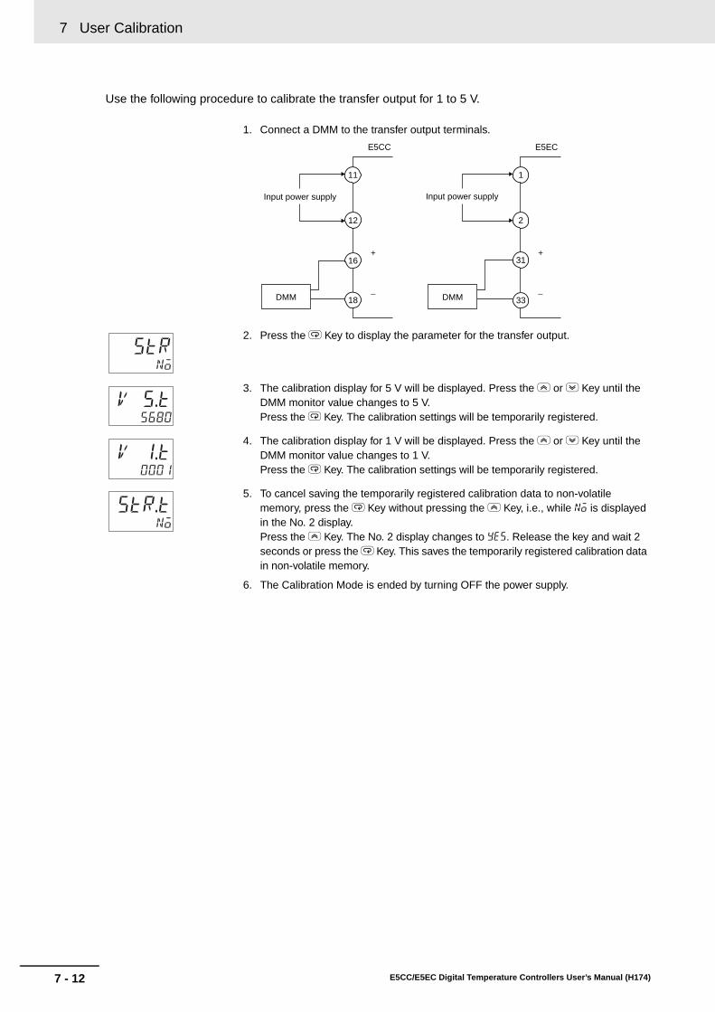
7 User Calibration
7 - 12 E5CC/E5EC Digital Temperature Controllers User’s Manual (H174)
Use the following procedure to calibrate the transfer output for 1 to 5 V.
1. Connect a DMM to the transfer output terminals.
2. Press the M Key to display the parameter for the transfer output.
3. The calibration display for 5 V will be displayed. Press the U or D Key until the DMM monitor value changes to 5 V.Press the M Key. The calibration settings will be temporarily registered.
4. The calibration display for 1 V will be displayed. Press the U or D Key until the DMM monitor value changes to 1 V.Press the M Key. The calibration settings will be temporarily registered.
5. To cancel saving the temporarily registered calibration data to non-volatile memory, press the M Key without pressing the U Key, i.e., while no is displayed in the No. 2 display.Press the U Key. The No. 2 display changes to yes. Release the key and wait 2 seconds or press the M Key. This saves the temporarily registered calibration data in non-volatile memory.
6. The Calibration Mode is ended by turning OFF the power supply.
Input power supply
DMM
E5CC
+
−
Input power supply
DMM
E5EC
+
−
11
12
16
18
1
2
31
33
strno
v 5.t5680
V 1.t0001
str.tno

7 - 13
7 User Calibration
E5CC/E5EC Digital Temperature Controllers User’s Manual (H174)
7-7 Ch
ecking
Ind
ication
Accu
racy
7
7-7 Checking Indication Accuracy
• After calibrating the input, be sure to check the indication accuracy to make sure that thecalibration has been executed correctly.
• Operate the E5CC/E5EC in the process value/set point monitor mode.• Check the indication accuracy at the following three values: upper limit, lower limit, and mid-point.• To check the range of an infrared sensor, set the input type parameter to 6 (i.e., a K thermocouple)
and input a voltage that is equivalent to the starting power of a K thermocouple.
Thermocouple or Infrared Temperature Sensor• Preparations
The diagram below shows the required device connections. Make sure that the E5CC/E5EC andcold junction compensator are connected by a compensating conductor for the thermocouple thatis to be used during actual operation.
• OperationMake sure that the cold junction compensator is at 0°C, and set the STV output to the voltageequivalent of the starting power of the check value.The cold junction compensator and compensation conductor are not required when an externalcold junction compensation method is used.
STV
23
24
1
2
E5EC
STV5
6
11
12
E5CC
−
+
Input power supply
Input power supply
Cold junction compensator
Compensating conductor
−
+
Cold junction compensator
Compensating conductor

7 User Calibration
7 - 14 E5CC/E5EC Digital Temperature Controllers User’s Manual (H174)
Resistance Thermometer• Preparations
The diagram below shows the required device connections.
• OperationSet the 6-dial variable resistor to the resistance that is equivalent to the test value.
Analog Input• PreparationsThe diagram below shows the required device connections.(The connection terminals depend on the model and input type.)
Current Input
A 4
5B'
B 6
11
12
E5CC
A 22
23B'
B 24
1
2
E5EC
Input power supply
6-dial variable resistor
Input power supply
6-dial variable resistor
STV4
5
Input power supply
11
12
E5CC
E5EC
Input power supply
1
222
STV23
−
+
−
+

7 - 15
7 User Calibration
E5CC/E5EC Digital Temperature Controllers User’s Manual (H174)
7-7 Ch
ecking
Ind
ication
Accu
racy
7
Voltage Input
• OperationSet the STV output to the voltage or current test value.
STV5
6
11
12
E5CC
E5EC1
223
STV24
Input power supply
Input power supply
−
+
−
+

7 User Calibration
7 - 16 E5CC/E5EC Digital Temperature Controllers User’s Manual (H174)

A - 1E5CC/E5EC Digital Temperature Controllers User’s Manual (H174)
A
A-1 Specifications . . . . . . . . . . . . . . . . . . . . . . . . . . . . . . . . . . . . . . . . . . . . . . . . . A-2A-1-1 Ratings . . . . . . . . . . . . . . . . . . . . . . . . . . . . . . . . . . . . . . . . . . . . . . . . . . . . . . . A-2A-1-2 Characteristics . . . . . . . . . . . . . . . . . . . . . . . . . . . . . . . . . . . . . . . . . . . . . . . . . A-4A-1-3 Rating and Characteristics of Options . . . . . . . . . . . . . . . . . . . . . . . . . . . . . . . A-5A-1-4 Waterproof Packing . . . . . . . . . . . . . . . . . . . . . . . . . . . . . . . . . . . . . . . . . . . . . . A-5
A-2 Current Transformer (CT) . . . . . . . . . . . . . . . . . . . . . . . . . . . . . . . . . . . . . . . A-7A-2-1 Specifications . . . . . . . . . . . . . . . . . . . . . . . . . . . . . . . . . . . . . . . . . . . . . . . . . . A-7A-2-2 Dimensions (Unit: mm) . . . . . . . . . . . . . . . . . . . . . . . . . . . . . . . . . . . . . . . . . . . A-7
A-3 USB-Serial Conversion Cable and Conversion Cable . . . . . . . . . . . . . . . . A-8A-3-1 E58-CIFQ2 USB-Serial Conversion Cable . . . . . . . . . . . . . . . . . . . . . . . . . . . . A-8A-3-2 E58-CIFQ2-E Conversion Cable . . . . . . . . . . . . . . . . . . . . . . . . . . . . . . . . . . . . A-9
A-4 Error Displays . . . . . . . . . . . . . . . . . . . . . . . . . . . . . . . . . . . . . . . . . . . . . . . . A-10
A-5 Troubleshooting . . . . . . . . . . . . . . . . . . . . . . . . . . . . . . . . . . . . . . . . . . . . . . A-13
A-6 Parameter Operation Lists . . . . . . . . . . . . . . . . . . . . . . . . . . . . . . . . . . . . . A-16A-6-1 Operation Level . . . . . . . . . . . . . . . . . . . . . . . . . . . . . . . . . . . . . . . . . . . . . . . . A-16A-6-2 Adjustment Level . . . . . . . . . . . . . . . . . . . . . . . . . . . . . . . . . . . . . . . . . . . . . . A-17A-6-3 Initial Setting Level . . . . . . . . . . . . . . . . . . . . . . . . . . . . . . . . . . . . . . . . . . . . . A-18A-6-4 Manual Control Level . . . . . . . . . . . . . . . . . . . . . . . . . . . . . . . . . . . . . . . . . . . A-21A-6-5 Monitor/Setting Item Level . . . . . . . . . . . . . . . . . . . . . . . . . . . . . . . . . . . . . . . A-21A-6-6 Advanced Function Setting Level . . . . . . . . . . . . . . . . . . . . . . . . . . . . . . . . . . A-22A-6-7 Protect Level . . . . . . . . . . . . . . . . . . . . . . . . . . . . . . . . . . . . . . . . . . . . . . . . . . A-26A-6-8 Communications Setting Level . . . . . . . . . . . . . . . . . . . . . . . . . . . . . . . . . . . . A-26A-6-9 Initialization According to Parameter Changes . . . . . . . . . . . . . . . . . . . . . . . . A-27
A-7 Sensor Input Setting Range, Indication Range, Control Range . . . . . . . A-30
A-8 Setting Levels Diagram . . . . . . . . . . . . . . . . . . . . . . . . . . . . . . . . . . . . . . . . A-31
A-9 Parameter Flow . . . . . . . . . . . . . . . . . . . . . . . . . . . . . . . . . . . . . . . . . . . . . . . A-32
Appendices

A Appendices
A - 2 E5CC/E5EC Digital Temperature Controllers User’s Manual (H174)
A-1 Specifications
*1 For input setting ranges, refer to A-7 Sensor Input Setting Range, Indication Range, Control Range.*2 When connecting the ES2-HB/THB, connect it 1:1.*3 With the E5CC, you cannot select a relay output or current output for control output 2.
A-1-1 Ratings
Supply voltage 100 to 240 VAC, 50/60 Hz 24 VAC, 50/60 Hz/24 VDC
Operating voltage range 85% to 110% of rated supply voltage
Power consumption
E5CCOption number 000: 5.2 VA max.Other option numbers: 6.5 VA max.
Option number 000: 3.1 VA max./1.6 W max.Other option numbers: 4.1 VA max./2.3 W max.
E5ECOption number 000: 6.6 VA max.Other option numbers: 8.3 VA max.
Option number 000: 4.1 VA max./2.3 W max.Other option numbers: 5.5 VA max./3.2 W max.
Sensor input *1
Thermocouple: K, J, T, E, L, U, N, R, S, B, W, PLIIPlatinum resistance thermometer: Pt100, JPt100Infrared temperature sensor: 10 to 70°C, 60 to 120°C, 115 to 165°C, 140 to 260°CCurrent input *2: 4 to 20 mA, 0 to 20 mA (Input impedance: 150 Ω max.)
Voltage input *2: 1 to 5 V, 0 to 5 V, 0 to 10 V (Input impedance: 1 MΩ min.)
Control output 1/2
Relay output
E5CCSPST-NO, 250 VAC, 3 A (resistive load), electrical durability: 100,000 operations
Min. applicable load: 5 V, 10 mA*3
E5ECSPST-NO, 250 VAC, 5 A (resistive load), electrical durability: 100,000 operationsMin. applicable load: 5 V, 10 mA
Voltage output
E5CCOutput voltage 12 VDC ±20% (PNP), max. load current 21 mA, with short-circuit protection circuit
E5EC
Control Output 1Output voltage 12 VDC ±20% (PNP), max. load current 40 mA, with short-circuit protection circuit(21 mA if there are two control outputs)
Control Output 2Control output 2: 12 VDC ±20% (PNP), max. load current 21 mA, with short-circuit protection circuit
Current output4 to 20 mA DC, 0 to 20 mA DC, Load: 500 Ω max.
Resolution: Approx. 10,000 *3
Auxiliary output Relay outputs
Two Auxiliary OutputsSPST-NO, 250 VAC, 3 A (resistive load), electrical durability: 100,000 operationsMin. applicable load: 5 V, 10 mA
Three Auxiliary Outputs (E5CC) or Four Auxiliary Outputs (E5EC)SPST-NO, 250 VAC, 2 A (resistive load), electrical durability: 100,000 operations, Min. applicable load: 5 V, 10 mA
Control method 2-PID or ON/OFF control
Setting method Digital setting using front panel keys
Indication method 11-segment digital displays and individual indicators
Other functions Depend on the model
Ambient temperature −10 to 55°C (with no condensation or icing); with 3-year guarantee: −10 to 50°CAmbient humidity 25% to 85%
Storage temperature −25 to 65°C (with no condensation or icing)
Altitude 2,000 m max.
Recommended fuse T2A, 250 VAC, time lag, low shut-off capacity
Installation environment Installation Category II, Pollution Class 2 (IEC 61010-1 compliant)

A - 3
A Appendices
E5CC/E5EC Digital Temperature Controllers User’s Manual (H174)
A-1 S
pecificatio
ns
A
A-1-1 R
atings
HB and HS Alarms(E5CC/E5EC Models with HB and HS Alarms)
*1 HB alarms are not detected and the heater power is not measured if the ON time for the control output forheating is 100 ms or less (30 ms or less if the control period is 0.1 or 0.2 s).
*2 HS alarms are not detected and the leakage power is not measured if the ON time for the control outputfor heating is 100 ms or less (35 ms or less if the control period is 0.1 or 0.2 s).
Max. heater current 50 A AC
Input current readout accuracy
±5% FS ±1 digit max.
Heater burnout alarm setting range
0.1 to 49.9 A (0.1 A units)0.0 A: Heater burnout alarm output turns OFF.50.0 A: Heater burnout alarm output turns ON.
Min. detection ON time *1: 30 ms for a control period of 0.1 s or 0.2 s100 ms for a control period of 0.5 s or 1 to 99 s
Heater short alarm setting range
0.1 to 49.9 A (0.1 A units)0.0 A: Heater short alarm output turns ON.50.0 A: Heater short alarm output turns OFF.
Min. detection OFF time *2: 35 ms for a control period of 0.1 s or 0.2 s100 ms for a control period of 0.5 s or 1 to 99 s

A Appendices
A - 4 E5CC/E5EC Digital Temperature Controllers User’s Manual (H174)
*1 The indication accuracy of K, T, and N thermocouples at a temperature of −100°C or less is ±2°C ±1 digit maximum.The indication accuracy of U and L thermocouples is ±2°C ±1 digit maximum.The indication accuracy of B thermocouples at a temperature of 400°C or less is not specified.The indication accuracy of B thermocouples at a temperature of 400 to 800°C is ±3°C maximum.The indication accuracy of R and S thermocouples at a temperature of 200°C or less is ±3°C ±1 digit maximum.The indication accuracy of W thermocouples is (±0.3% of PV or ±3°C, whichever is greater) ±1 digit maximum.The indication accuracy of PLII thermocouples is (±0.3% of PV or ±2°C, whichever is greater) ±1 digit maximum.
*2 Ambient temperature: −10°C to 23°C to 55°CVoltage range: −15 to +10% of rated voltage
*3 The unit is determined by the setting of the Integral/Derivative Time Unit parameter.
A-1-2 Characteristics
Indication accuracy(ambient temperature of 23°C)
Thermocouple *1 (±0.3% of PV or ±1°C, whichever is greater) ±1 digit max.
Resistance thermometer
(±0.2% of PV or ±0.8°C, whichever is greater) ±1 digit max.
Analog input ±0.2% FS ±1 digit max.
CT input ±5% FS ±1 digit max.
Temperature variation
influence *2
Voltage variation influence *2
Thermocouple
Thermocouple (R, S, B, W, PLII)(±1% of PV or ±10°C, whichever is greater) ±1 digit max.Other thermocouples:(±1% of PV or ±4°C, whichever is greater) ±1 digit max. *K thermocouple at −100°C max: ±10°C max.
Resistance thermometer
(±1% of PV or ±2°C, whichever is greater) ±1 digit max.
Analog input ±1% FS ±1 digit max.CT input ±5% FS ±1 digit max.
Remote SP input ±1% FS ±1 digit max.
HysteresisTemperature input 0.1 to 999.9°C or °F (in units of 0.1°C or °F)Analog input 0.01% to 99.99% FS (in units of 0.01% FS)
Proportional band (P)Temperature input 0.1 to 999.9°C or °F (in units of 0.1°C or °F)
Analog input 0.1% to 999.9% FS (in units of 0.1% FS)
Integral time (I) *30 to 9,999 s (in units of 1 s)0.0 to 999.9 s (in units of 0.1 s)
Derivative time (D) *30 to 9,999 s (in units of 1 s)0.0 to 999.9 s (in units of 0.1 s)
Control Period 0.1, 0.2, 0.5, or 1 to 99 s (in units of 1 s)Manual reset value 0.0% to 100.0% (in units of 0.1%)
Alarm setting range −1,999 to 9,999 (decimal point position depends on input type)
Sampling cycle 50 ms
Insulation resistance 20 MΩ min. (at 500 VDC)Dielectric strength 2,300 VAC, 50/60 Hz for 1 min between terminals of different charge
Malfunction vibration 10 to 55 Hz, 20 m/s2 for 10 min each in X, Y and Z directions
Vibration resistance 10 to 55 Hz, 20 m/s2 for 2 hr each in X, Y, and Z directions
Malfunction shock 100 m/s2, 3 times each in X, Y, and Z directions
Shock resistance 300 m/s2, 3 times each in X, Y, and Z directions
WeightE5CC
Approx. 120 g Adapter: Approx. 10 g
Terminal cover: Approx. 0.5 g each
E5ECApprox. 210 g Adapter:
Approx. 4 g × 2Terminal Cover: Approx. 1 g each
Degree of protection Front panel: IP66, rear case: IP20, terminals: IP00
Memory protection Non-volatile memory (number of writes: 1,000,000)

A - 5
A Appendices
E5CC/E5EC Digital Temperature Controllers User’s Manual (H174)
A-1 S
pecificatio
ns
A
A-1-3 R
ating and Characteristics of O
ptions
If the Waterproof Packing is lost or damage, order one of the following models.
A-1-3 Rating and Characteristics of Options
Event inputs
Contact InputON: 1 kΩ max., OFF: 100 kΩ min.
Non-contact InputON: Residual voltage 1.5 V max.; OFF: Leakage current 0.1 mA max.
Communications
Transmission path: RS-485
Communications method: RS-485 (2-wire, half duplex)
Synchronization: Start-stopBaud rate: 9.6, 19.2, 38.4, or 57.6 kbps
Transfer outputCurrent output: 4 to 20 mA DC, Load: 500 Ω max., Resolution: 10,000 ±0.3%
Linear voltage output: 1 to 5 VDC, Load: 1 kΩ min., Resolution: 10,000 ±0.3%
Remote SP inputCurrent input: 4 to 20 or 0 to 20 mA DC with input impedance of 150 Ω max.Voltage input: 1 to 5, 0 to 5, or 0 to 10 VDC with input impedance of 1 MΩ min.
A-1-4 Waterproof Packing
Y92S-P8 (for DIN 48 × 48) Y92S-P9 (for DIN 48 × 96)

A Appendices
A - 6 E5CC/E5EC Digital Temperature Controllers User’s Manual (H174)
A Y92F-P7 Setup Tool Port Cover for the front panel is included with the E5EC. Order this Port Coverseparately if the Port Cover on the front-panel Setup Tool port is lost or damaged. The WaterproofPacking must be periodically replaced because it may deteriorate, shrink, or harden depending on theoperating environment.
Use the following procedure to replace the Setup Tool Port Cover for the front panel.
Replacement Procedure
A-1-5 Setup Tool Port Cover for Front Panel
Y92S-P7
1 Open the Setup Tool Port Cover on the front panel.
2 Pull gently on the Setup Tool Port Cover to remove it from theDigital Controller.
3 Insert the stopper on the Setup Tool Port Cover into the hole atthe bottom of the port.
4 Make sure that the Setup Tool Port Cover is closed.
Insertion hole

A - 7
A Appendices
E5CC/E5EC Digital Temperature Controllers User’s Manual (H174)
A-2 C
urren
t Transfo
rmer (C
T)
A
A-2-1 S
pecifications
A-2 Current Transformer (CT)
*1 The maximum continuous current of the E5CC/E5EC is 50 A.
• E54-CT1
• E54-CT3
A-2-1 Specifications
Item SpecificationsModel number E54-CT1 E54-CT3
Max. continuous current 50 A 120 A *1
Dielectric strength 1,000 VAC (for 1 min)
Vibration resistance 50 Hz, 98 m/s2
Weight Approx. 11.5 g Approx. 50 g
Accessories None Armature (2), Plug (2)
A-2-2 Dimensions (Unit: mm)
2115
25
3
10
30
40
2.8
5.8 dia.
Two, 3.8 dia.
10.5
7.5
30
40
15
9
12 dia.
Two, M3 holes, depth: 4
2.36 dia.
40
30

A Appendices
A - 8 E5CC/E5EC Digital Temperature Controllers User’s Manual (H174)
A-3 USB-Serial Conversion Cable and Conversion Cable
A USB-Serial Conversion Cable is used to connect the E5CC/E5EC to a computer. The E58-CIFQ2-EConversion Cable is also required to connect to the Setup Tool port on the front panel of the E5EC. Thefollowing table lists the cables and ports that are used.
Refer to 2-4 Using the Setup Tool Port for the connection procedure.
Specifications
Note: Use a high-power port for the USB port.
Model Connection port CableE5CC Top-panel Setup Tool port E58-CIFQ2 USB-Serial Conversion Cable
E5EC Top-panel Setup Tool port E58-CIFQ2 USB-Serial Conversion CableFront-panel Setup Tool port
E58-CIFQ2 USB-Serial Conversion Cable and E58-CIFQ2-E Conversion Cable
A-3-1 E58-CIFQ2 USB-Serial Conversion Cable
Item SpecificationsApplicable OS Windows 2000, XP, Vista, or 7
Applicable software CX-Thermo
Applicable models E5CB Series and E5CC/E5EC SeriesUSB interface rating Conforms to USB Specification 2.0
DTE speed 38,400 bps
Connector specifications
Computer end: USB (type A plug)Digital Controller: Special serial connector
Power supply Bus power (Supplied from USB host controller)
Power supply voltage 5 VDC
Current consumption 450 mA max.Output voltage 4.7±0.2 VDC (Supplied through USB-Serial Conversion Cable to the Digital
Controller.)
Output current 250 mA max. (Supplied through USB-Serial Conversion Cable to the Digital Controller.)
Ambient temperature 0 to 55°C (with no condensation or icing)Ambient humidity 10% to 80%
Storage temperature −20 to 60°C (with no condensation or icing)
Storage humidity 10% to 80%Altitude 2,000 m max.
Weight Approx. 120 g

A - 9
A Appendices
E5CC/E5EC Digital Temperature Controllers User’s Manual (H174)
A-3 U
SB
-Serial C
onversio
n C
able an
d C
onversio
n C
able
A
A-3-2 E
58-CIF
Q2-E
Conversion C
able
Dimensions
LED Indicator Display
Specifications
DimensionsE58-CIFQ2-E Conversion Cable
Connected to the E58-CIFQ2 USB-Serial Conversion Cable
Indicator Color Status MeaningPWR Green Lit. USB bus power is being supplied.
Not lit. USB bus power is not being supplied.SD Yellow Lit Sending data from USB-Serial Conversion Cable
Not lit Not sending data from USB-Serial Conversion Cable
RD Yellow Lit Receiving data from the USB-Serial Conversion CableNot lit Not receiving data from the USB-Serial Conversion Cable
A-3-2 E58-CIFQ2-E Conversion Cable
Item SpecificationApplicable models E5EC Series
Connector specifications
Digital Controller: 4-pin plugE58-CIFQ2: Small special connector
Ambient temperature 0 to 55°C (with no condensation or icing)Ambient humidity 10% to 80%
Storage temperature −20 to 60°C (with no condensation or icing)
Storage humidity 10% to 80%Altitude 2,000 m max.
Weight Approx. 60 g
250 mm
(2,110 mm)
263 mm 1,510 mmRD indicator
SD indicator
PWR indicator
(1510 mm)
250 mm
(2,110 mm)
263 mm 1,510 mm

A Appendices
A - 10 E5CC/E5EC Digital Temperature Controllers User’s Manual (H174)
A-4 Error Displays
When an error occurs, the error contents are shown on the No. 1 or the No. 2 display.This section describes how to check error codes on the display, and the actions to be taken to remedythe problems.
MeaningThe input value has exceeded the control range. *The input type setting is not correct. The sensor is disconnected or shorted. The sensor wiring is not correct. The sensor is not wired.
* Control Range
ActionCheck the wiring of inputs for miswiring, disconnections, and short-circuits and check the input type.If no abnormality is found in the wiring and input type, turn the power OFF then back ON again.If the display remains the same, the Controller must be replaced. If the display is restored, then theprobable cause is electrical noise affecting the control system. Check for electrical noise.Note: With resistance thermometer input, a break in the A, B, or B' line is regarded as a disconnection.
OperationAfter an error occurs, the error is displayed and the alarm outputs function as if the upper limit hasbeen exceeded.It will also operate as if transfer output exceeded the upper limit. If an input error is assigned to acontrol output or auxiliary output, the output will turn ON when the input error occurs. The errormessage will appear in the display for the PV.Note: The heating and cooling control outputs will turn OFF. When the manual MV, MV at stop, or MV at error
is set, the control output is determined by the set value.
s.err Input Error
Resistance thermometer, thermocouple input:
Temperature setting lower limit −20°C to temperature setting upper limit +20°C(Temperature setting lower limit −40°F to temperature setting upper limit +40°F)
ES1B input: Same as input indication range
Analog input: −5% to +105% of scaling range

A - 11
A Appendices
E5CC/E5EC Digital Temperature Controllers User’s Manual (H174)
A-4 E
rror D
isplays
A
MeaningThough this is not an error, it is displayed if the process value exceeds the display range when thecontrol range is larger than the display range.The display ranges are shown below (with decimal points omitted).• When less than −1,999: [[[[• When more than 9,999: ]]]]
OperationControl continues, allowing normal operation. The value will appear in the display for the PV.
MeaningThere is an error in internal circuits.
ActionFirst, turn the power OFF then back ON again. If the display remains the same, the Controller mustbe repaired. If the display is restored, then the probable cause is electrical noise affecting the controlsystem. Check for electrical noise.
OperationThe control, auxiliary, and transfer outputs turn OFF. (A current output will be approx. 0 mA. A linearvoltage output will be approx. 0 V.)
[[[[
]]]]Display Range Exceeded
e333 AD Converter Error
−1999 9999 −1999 9999
Resistance thermometer input (Except for models with a setting range of −199.9 to 500.0°C)Thermocouple input (Except for models with a setting range of −199.9 to 400.0°C)ES1B Control range
s.err display Numeric display s.err display
Input indication range
Analog Input• When display range < control range
Control range
s.err display [[[[ display Numeric display
Input indication range
]]]] display s.err display
Resistance thermometer input (Except for models with a setting range of −1999. to 500.0°C)Thermocouple input (Except for models with a setting range of −199.9 to 400.0°C)
Control range
s.err display [[[[ display Numeric display
Input indication range
s.err display
Analog Input• When display range ≥ control range
Control range
s.err display Numeric display s.err display
Display range*
*The display range is shown in numbers with decimal points omitted.
Input indication range
Display range*

A Appendices
A - 12 E5CC/E5EC Digital Temperature Controllers User’s Manual (H174)
MeaningInternal memory operation is in error.
ActionFirst, turn the power OFF then back ON again. If the display remains the same, the Controller mustbe repaired. If the display is restored, then the probable cause is electrical noise affecting the controlsystem. Check for electrical noise.
OperationThe control, auxiliary, and transfer outputs turn OFF. (A current output will be approx. 0 mA. A linearvoltage output will be approx. 0 V.)
MeaningThis error is displayed when the heater current value exceeds 55.0 A.
OperationControl continues, allowing normal operation. An error message is displayed when the followingitems are displayed.Heater current 1 value monitorHeater current 2 value monitorLeakage current 1 monitorLeakage current 2 monitor
MeaningIf there is an HB or HS alarm, the relevant parameter will flash on the No. 1 display.
OperationThe relevant Heater Current 1 Value Monitor, Heater Current 2 Value Monitor, Leakage Current 1Monitor, or Leakage Current 2 Monitor parameters in the Operation or Adjustment Level will flash onthe No. 1 display. However, control continues and operation is normal.
e111 Memory Error
ffff Current Value Exceeds
ct1
ct2
lcr1
lcr2
HB AlarmHS Alarm

A - 13
A Appendices
E5CC/E5EC Digital Temperature Controllers User’s Manual (H174)
A-5 Tro
ub
lesho
otin
g
A
A-5 Troubleshooting
Checking ProblemsIf the Digital Controller is not operating normally, check the following points before requesting repairs. Ifthe problem persists, contact your OMRON representative for details on returning the product.
* Refer to the E5CC/E5EC Digital Temperature Controllers Communications Manual (Cat. No. H175) for details.
Timing Status Meaning Countermeasures Page
Turning ON the power for the first time
The TUNE indicator will flash.
ST (self-tuning) is in progress (default setting: ON).
This is not a product fault.The TUNE indicator flashes during self-tuning.
4-25
Temperature error is large.Input error (S.Err display)
Input type mismatch Check the sensor type and reset the input type correctly. 4-11
Thermometer is not installed properly.
Check the thermometer installation location and polarity and install correctly.
2-8, 2-12
Communications are not possible.
Non-recommended adapter is being used.
Make sure that the connected device is not faulty. *
During operation
OvershootingUndershootingHunting
ON/OFF control is enabled (default: ON/OFF control selected).
Select PID control and execute either ST (self-tuning) or AT (auto-tuning). When using self-tuning, turn ON the power supply to the Digital Controller and load (heater, etc.) at the same time, or turn ON the load power supply first. Accurate self-tuning and optimum control will not be possible if the power supply to the load is turned ON after turning ON the power supply to the Digital Controller.
4-23
Control period is longer compared with the speed of rise and fall in temperature.
Shorten the control period. A shorter control period improves control performance, but a cycle of 20 ms minimum is recommended in consideration of the service life of the relays.
4-14
Unsuitable PID constant Set appropriate PID constants using either of the following methods.• Execute AT (autotuning).• Set PID constants individually using manual settings.
4-23
HS alarm operation fault Use breeder resistance if the problem is due to leakage current. Also investigate the errors detected by the HS alarm function.
4-41
Temperature is not rising Specified operation is unsuitable for required control (default: Reverse operation).
Select either forward or reverse operation depending on the required control. Reverse operation is used for heating operations.
4-14
Heater is burnt out or deteriorated.
Check whether heater burnout or deterioration have occurred. Also investigate the errors detected by the heater burnout alarm.
4-39
Insufficient heater capacity
Check whether the heater's heating capacity is sufficient. ---
Cooling system in operation.
Check whether a cooling system is operating. ---
Peripheral devices have heat prevention device operating.
Set the heating prevention temperature setting to a value higher than the set temperature of the Digital Controller.
---

A Appendices
A - 14 E5CC/E5EC Digital Temperature Controllers User’s Manual (H174)
Timing Status Meaning Countermeasures Page
During operation (continued)
Output will not turn ON Set to STOP (default: RUN)
Set the RUN/STOP mode to RUN. If STOP is lit on the display, control is stopped.
5-12
Specified operation is unsuitable for required control (default: Reverse operation).
Select either forward or reverse operation depending on the required control. Reverse operation is used for heating operations.
4-14
A high hysteresis is set for ON/OFF operation (default: 1.0°C)
Set a suitable value for the hysteresis. 4-20
The specified power is not being supplied from the terminals.
The output will not turn ON while the Digital Controller is being operated with power supplied through the USB-Serial Conversion Cable. Supply the specified power from the terminals.
---
Temperature Controller will not operate
Set to STOP (default: RUN)
Set the RUN/STOP mode to RUN. If STOP is lit on the display, control is stopped.
5-12
Temperature error is largeInput error (S.err display)
Thermometer has burnt out or short-circuited.
Check whether the thermometer has burnt out or short-circuited.
---
Thermometer lead wires and power lines are in the same conduit, causing noise from the power lines (generally, display values will be unstable).
Wire the lead wires and power lines in separate conduits, or wire them using a more direct path.
---
Connection between the Digital Controller and thermocouple is using copper wires.
Connect the thermocouple's lead wires directly, or connect a compensating conductor suitable for the thermocouple.
---
Installation location of thermometer is unsuitable.
Make sure that the location that is being measured with the temperature sensor is suitable.
---
Input shift is not set correctly (default: 0°C)
Set a suitable input shift. If input shift is not required, set the input shift value to 0.0.
5-3
Keys will not operate Setting change protect is ON.
Turn OFF setting change protect. 5-19
Cannot shift levels Operations limited due to protection.
Set the operation/adjustment protect, initial setting/communications protect, and setting change protect values as required.
5-20
After long service life
Control is unstable Terminal screws may be loose.
Retighten terminal screws to a torque of 0.43 to 0.58 N·m. 2-16
The internal components have reached the end of their service life.
The Digital Controller's internal electrolytic capacitor depends on the ambient temperature, and load rate. The structural life depends on the ambient environment (shock, vibration). The life expectancy of the output relays varies greatly with the switching capacity and other switching conditions. Always use the output relays within their rated load and electrical life expectancy. If an output relay is used beyond its life expectancy, its contacts may become welded or burned. Replace the Digital Controller and all other Digital Controllers purchased in the same time period.
---

A - 15
A Appendices
E5CC/E5EC Digital Temperature Controllers User’s Manual (H174)
A-5 Tro
ub
lesho
otin
g
A
Symptom: Cannot Communicate or a Communications Error Occurs
* Refer to the E5CC/E5EC Digital Temperature Controllers Communications Manual (Cat. No. H175) forerror details.
Meaning Countermeasures
The communications wiring is not correct. Correct the wiring.
The communications line has become disconnected.
Connect the communications line securely and tighten the screws.
The communications cable is broken. Replace the cable.
The communications cable is too long. The total cable length for RS-485 is 500 m max.
The wrong communications cable has been used.
Use a shielded, AWG24 to AWG18 (cross-sectional area of 0.205 to 0.823
mm2) twisted-pair cable for the communications cable.
More than the specified number of communications devices are connected to the same communications path.
When 1:N communications are used, a maximum of 32 nodes may be connected, including the host node.
An end node has not been set at each end of the communications line.
Set or connect terminating resistance at each end of the line. If the E5CC/E5EC is the end node, 120-Ω (1/2-W) terminating resistance is used. Be sure that the combined resistance with the host device is 54 Ω minimum.
The specified power supply voltage is not being supplied to the Controller.
Supply the specified power supply voltage.
The specified power supply voltage is not being supplied to an Interface Converter (such as the K3SC).
Supply the specified power supply voltage.
The same baud rate and communications method are not being used by all of the Controllers, host devices, and other devices on the same communications line.
Set the same values for the baud rate, protocol, data length, stop bits, and parity on all nodes.
The unit number specified in the command frame is different from the unit number set by the Controller.
Use the same unit number.
The same unit number as the Controller is being used for another node on the same communications line.
Set each unit number for only one node.
There is a mistake in programming the host device.
Use a line monitor to check the commands. Check operation using a sample program.
The host device is detecting the absence of a response as an error before it receives the response from the Controller.
Shorten the send data wait time in the Controller or increase the response wait time in the host device.
The host device is detecting the absence of a response as an error after broadcasting a command.
The Controller does not return responses for broadcast commands.
The host device sent another command before receiving a response from the Controller.
The response must always be read after sending a command (except for broadcast commands).
The host device sent the next command too soon after receiving a response from the Controller.
After receiving a response, wait at least 2 ms before sending the next command.
The communications line became unstable when Controller power was turned ON or interrupted, and the host device read the unstable status as data.
Initialize the reception buffer in the host device before sending the first command and after turning OFF the power to the Controller.
The communications data was corrupted from noise from the environment.
Try using a slower baud rate.Separate the communications cable from the source of noise.Use a shielded, twisted-pair cable for the communications cable.Use as short a communications cable as possible, and do not lay or loop extra cable.To prevent inductive noise, do not run the communications cable parallel to a power line.If noise countermeasures are difficult to implement, use an Optical Interface.

A Appendices
A - 16 E5CC/E5EC Digital Temperature Controllers User’s Manual (H174)
A-6 Parameter Operation Lists
A-6-1 Operation Level
Parameters Characters Setting (monitor) value Display Default Unit
Process Value Temperature: According to indication range for each sensor.Analog: Scaling lower limit −5% FS to Scaling upper limit +5% FS
EU
Set Point SP lower limit to SP upper limit 0 EU
Multi-SP Set Point Selection
m-sp 0 to 7 0 None
Remote SP Monitor rsp Remote SP lower limit −10%FS to remote SP upper limit + 10%FS
EU
Set Point During SP Ramp
sp-m SP lower limit to SP upper limit EU
Heater Current 1 Value Monitor
ct1 0.0 to 55.0 A
Heater Current 2 Value Monitor
ct2 0.0 to 55.0 A
Leakage Current 1 Monitor
lcr1 0.0 to 55.0 A
Leakage Current 2 Monitor
lcr2 0.0 to 55.0 A
Program Start prst RSET, STRT rset, strt RSET None
Soak Time Remain sktr 0 to 9999 min or h
RUN/STOP r-s RUN/STOP run, stop Run None
Alarm Value 1 al-1 All alarms except for MV absolute-value upper-limit or lower-limit alarms: −1,999 to 9,999
0 EU
MV absolute-value upper-limit or lower-limit alarms: −199.9 to 999.9
0.0 %
Alarm Value Upper Limit 1 al1h −1,999 to 9,999 0 EU
Alarm Value Lower Limit 1 al1l −1,999 to 9,999 0 EU
Alarm Value 2 al-2 All alarms except for MV absolute-value upper-limit or lower-limit alarms: −1,999 to 9,999
0 EU
MV absolute-value upper-limit or lower-limit alarms: −199.9 to 999.9
0.0 %
Alarm Value Upper Limit 2 al2h −1,999 to 9,999 0 EU
Alarm Value Lower Limit 2 al2l −1,999 to 9,999 0 EU
Alarm Value 3 al-3 All alarms except for MV absolute-value upper-limit or lower-limit alarms: −1,999 to 9,999
0 EU
MV absolute-value upper-limit or lower-limit alarms: −199.9 to 999.9
0.0 %
Alarm Value Upper Limit 3 al3h −1,999 to 9,999 0 EU
Alarm Value Lower Limit 3 al3l −1,999 to 9,999 0 EU
Alarm Value 4 al-4 All alarms except for MV absolute-value upper-limit or lower-limit alarms: −1,999 to 9,999
0 EU
MV absolute-value upper-limit or lower-limit alarms: −199.9 to 999.9
0.0 %
Alarm Value Upper Limit 4 al4h −1,999 to 9,999 0 EU
Alarm Value Lower Limit 4 al4l −1,999 to 9,999 0 EU
MV Monitor (Heating) o −5.0 to 105.5 (standard)0.0 to 105.0 (heating/cooling)
%
MV Monitor (Cooling) c-o 0.0 to 105.0 %

A - 17
A Appendices
E5CC/E5EC Digital Temperature Controllers User’s Manual (H174)
A-6 P
arameter O
peratio
n L
ists
A
A-6-2 A
djustment Level
A-6-2 Adjustment Level
Parameters Characters Setting (monitor) value Display Default Unit
Adjustment Level Display
l.adj
AT Execute/Cancel at OFF, AT CancelAT-2: 100%AT ExecuteAT-1: 40%AT Execute
off, at-2, at-1
OFF None
Communications Writing
cmwt OFF, ON off, on OFF None
SP Mode spmd LSP, RSP lsp, rsp LSP None
Heater Current 1 Value Monitor
ct1 0.0 to 55.0 A
Heater Burnout Detection 1
hb1 0.0 to 50.0 0.0 A
Heater Current 2 Value Monitor
ct2 0.0 to 55.0 A
Heater Burnout Detection 2
hb2 0.0 to 50.0 0.0 A
Leakage Current 1 Monitor
lcr1 0.0 to 55.0 A
HS Alarm 1 hs1 0.0 to 50.0 50.0 A
Leakage Current 2 Monitor
lcr2 0.0 to 55.0 A
HS Alarm 2 hs2 0.0 to 50.0 50.0 A
SP 0 sp-0 SP lower limit to SP upper limit 0 EU
SP 1 sp-1 SP lower limit to SP upper limit 0 EU
SP 2 sp-2 SP lower limit to SP upper limit 0 EU
SP 3 sp-3 SP lower limit to SP upper limit 0 EU
SP 4 sp-4 SP lower limit to SP upper limit 0 EU
SP 5 sp-5 SP lower limit to SP upper limit 0 EU
SP 6 sp-6 SP lower limit to SP upper limit 0 EU
SP 7 sp-7 SP lower limit to SP upper limit 0 EU
Process Value Input Shift
ins Temperature input: −199.9 to 999.9 0.0 °C or °FAnalog input: −1,999 to 9,999 0 EU
Process Value Slope Coefficient
inrt 0.001 to 9.999 1.000 None
Remote SP Input Shift rss Temperature input: −199.9 to 999.9 0.0 °C or °FAnalog input: −1,999 to 9,999 0 EU
Remote SP Input Slope Coefficient
rsrt 0.001 to 9.999 1.000 None
Proportional Band p Temperature input: 0.1 to 999.9 8.0 °C or °FAnalog input: 0.1 to 999.9 10.0 %FS
Integral Time i Integral/Derivative Time Unit of 1 s: 0 to 9,999Integral/Derivative Time Unit of 0.1 s: 0.0 to 999.9
233233.0
Seconds
Derivative Time d Integral/Derivative Time Unit of 1 s: 0 to 9,999Integral/Derivative Time Unit of 0.1 s: 0.0 to 999.9
4040.0
Seconds
Proportional Band (Cooling)
c-p Temperature input: 0.1 to 999.9 8.0 °C or °FAnalog input: 0.1 to 999.9 10.0 %FS
Integral Time (Cooling) c-i Integral/Derivative Time Unit of 1 s: 0 to 9,999Integral/Derivative Time Unit of 0.1 s: 0.0 to 999.9
233233.0
Seconds
Derivative Time (Cooling)
c-d Integral/Derivative Time Unit of 1 s: 0 to 9,999Integral/Derivative Time Unit of 0.1 s: 0.0 to 999.9
4040.0
Seconds
Dead Band c-db Temperature input: −199.9 to 999.9 0.0 °C or °FAnalog input: −19.99 to 99.99 0.00 %FS
Manual Reset Value of-r 0.0 to 100.0 50.0 %
Hysteresis (Heating) hys Temperature input: 0.1 to 999.9 1.0 °C or °FAnalog input: 0.01 to 99.99 0.10 %FS
Hysteresis (Cooling) chys Temperature input: 0.1 to 999.9 1.0 °C or °FAnalog input: 0.01 to 99.99 0.10 %FS
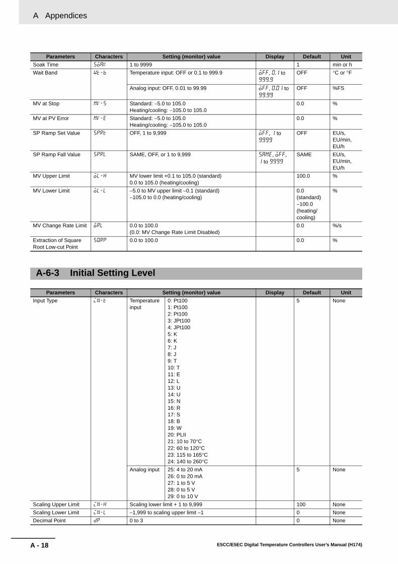
A Appendices
A - 18 E5CC/E5EC Digital Temperature Controllers User’s Manual (H174)
Soak Time soak 1 to 9999 1 min or h
Wait Band wt-b Temperature input: OFF or 0.1 to 999.9 off, 0.1 to 999.9
OFF °C or °F
Analog input: OFF, 0.01 to 99.99 off, 0.01 to 99.99
OFF %FS
MV at Stop mv-s Standard: −5.0 to 105.0Heating/cooling: −105.0 to 105.0
0.0 %
MV at PV Error mv-e Standard: −5.0 to 105.0Heating/cooling: −105.0 to 105.0
0.0 %
SP Ramp Set Value sprt OFF, 1 to 9,999 off, 1 to 9999
OFF EU/s, EU/min, EU/h
SP Ramp Fall Value sprl SAME, OFF, or 1 to 9,999 same, off, 1 to 9999
SAME EU/s, EU/min, EU/h
MV Upper Limit ol-h MV lower limit +0.1 to 105.0 (standard)0.0 to 105.0 (heating/cooling)
100.0 %
MV Lower Limit ol-l −5.0 to MV upper limit −0.1 (standard)−105.0 to 0.0 (heating/cooling)
0.0 (standard)−100.0 (heating/cooling)
%
MV Change Rate Limit orl 0.0 to 100.0(0.0: MV Change Rate Limit Disabled)
0.0 %/s
Extraction of Square Root Low-cut Point
sqrp 0.0 to 100.0 0.0 %
A-6-3 Initial Setting Level
Parameters Characters Setting (monitor) value Display Default Unit
Input Type in-t Temperature input
0: Pt1001: Pt1002: Pt1003: JPt1004: JPt1005: K6: K7: J8: J9: T10: T11: E12: L13: U14: U15: N16: R17: S18: B19: W20: PLII21: 10 to 70°C22: 60 to 120°C23: 115 to 165°C24: 140 to 260°C
5 None
Analog input 25: 4 to 20 mA26: 0 to 20 mA27: 1 to 5 V28: 0 to 5 V29: 0 to 10 V
5 None
Scaling Upper Limit in-h Scaling lower limit + 1 to 9,999 100 None
Scaling Lower Limit in-l −1,999 to scaling upper limit −1 0 None
Decimal Point dp 0 to 3 0 None
Parameters Characters Setting (monitor) value Display Default Unit

A - 19
A Appendices
E5CC/E5EC Digital Temperature Controllers User’s Manual (H174)
A-6 P
arameter O
peratio
n L
ists
A
A-6-3 Initial S
etting Level
Temperature Unit d-u °C, °F c, f °C None
SP Upper Limit sl-h Temperature input: SP lower limit + 1 to Input setting range upper limit
1300 EU
Analog input: SP lower limit + 1 to scaling upper limit 100
SP Lower Limit sl-l Temperature input: Input setting range lower limit to SP upper limit − 1
−200 EU
Analog input: Scaling lower limit to SP upper limit − 1 0
PID ON/OFF cntl ON/OFF 2-PID onof, pid ON/OFF None
Standard or Heating/Cooling
s-hc Standard or heating/cooling stnd, h-c Standard None
ST st OFF, ON off, on ON None
Program Pattern ptrn OFF, STOP, CONT off, stop, cont
OFF None
Control Period (Heating)
cp 0.1, 0.2, 0.5, or 1 to 99 0.1, 0.2, 0.5, 1 to 99
Relay output: 20Voltage output (for driving SSR): 2
Seconds
Control Period (Cooling)
c-cp 0.1, 0.2, 0.5, or 1 to 99 0.1, 0.2, 0.5, 1 to 99
Relay output: 20Voltage output (for driving SSR): 2
Seconds
Direct/Reverse Operation
orev Reverse operation, direct operation or-r, or-d Reverse operation
None
Alarm 1Type alt1 0: Alarm function OFF1: Upper and lower-limit alarm2: Upper-limit alarm3: Lower-limit alarm4: Upper and lower-limit range alarm5: Upper- and lower-limit alarm with standby sequence6: Upper-limit alarm with standby sequence7: Lower-limit alarm with standby sequence8: Absolute-value upper-limit alarm9: Absolute-value lower-limit alarm10: Absolute-value upper-limit alarm with standby sequence11: Absolute-value lower-limit alarm with standby sequence12: LBA (Loop Burnout Alarm)13: PV change rate alarm14: SP absolute-value upper-limit alarm15: SP absolute-value lower-limit alarm16: MV absolute-value upper-limit alarm17: MV absolute-value lower-limit alarm
18: RSP absolute-value upper-limit alarm *1
19: RSP absolute-value lower-limit alarm *1
2 None
Alarm 1 Hysteresis alh1 Temperature input: 0.1 to 999.9 for all alarms except for MV absolute-value upper-limit or MV lower-limit alarms
0.2 °C or °F
Analog input: 0.01 to 99.99 for all alarms except for MV absolute-value upper-limit or MV lower-limit alarms
0.02 %FS
0.01 to 99.99 for MV absolute-value upper-limit or MV lower-limit alarms
0.50 %
Alarm 2 Type alt2 Same as Alarm 1 Type except that 12 (LBA) cannot be set.
2 None
Parameters Characters Setting (monitor) value Display Default Unit

A Appendices
A - 20 E5CC/E5EC Digital Temperature Controllers User’s Manual (H174)
Alarm 2 Hysteresis alh2 Temperature input: 0.1 to 999.9 for all alarms except for MV absolute-value upper-limit or MV lower-limit alarms
0.2 °C or °F
Analog input: 0.01 to 99.99 for all alarms except for MV absolute-value upper-limit or MV lower-limit alarms
0.02 %FS
0.01 to 99.99 for MV absolute-value upper-limit or MV lower-limit alarms
0.50 %
Alarm 3 Type alt3 Same as Alarm 1 Type except that 12 (LBA) cannot be set.
2 None
Alarm 3 Hysteresis alh3 Temperature input: 0.1 to 999.9 for all alarms except for MV absolute-value upper-limit or MV lower-limit alarms
0.2 °C or °F
Analog input: 0.01 to 99.99 for all alarms except for MV absolute-value upper-limit or MV lower-limit alarms
0.02 %FS
0.01 to 99.99 for MV absolute-value upper-limit or MV lower-limit alarms
0.50 %
Alarm 4 Type alt4 Same as Alarm 1 Type except that 12 (LBA) cannot be set.
2 None
Alarm 4 Hysteresis alh4 Temperature input: 0.1 to 999.9 for all alarms except for MV absolute-value upper-limit or MV lower-limit alarms
0.2 °C or °F
Analog input: 0.01 to 99.99 for all alarms except for MV absolute-value upper-limit or MV lower-limit alarms
0.02 %FS
0.01 to 99.99 for MV absolute-value upper-limit or MV lower-limit alarms
0.50 %
Control Output 1 Signal o1st 4-20: 4-20 mA0-20: 0-20 mA
4-20, 0-20 4-20 None
Control Output 2 Signal o2st 4-20: 4-20 mA0-20: 0-20 mA
4-20, 0-20 4-20 None
Transfer Output Signal trst 4-20: 4-20 mA1-5V: 1-5 V
4-20, 1-5V 4-20 None
Transfer Output Type tr-t OFF: OFF
SP: Set point*2
SP-M: Ramp set pointPV: Process valueMV: Manipulated variable (heating)
C-MV: Manipulated variable (cooling)*3
off
sp
sp-m
pv
mv
c-mv
OFF None
Transfer Output Upper Limit
tr-h *4 *4 *4
Transfer Output Lower Limit
tr-l *4 *4 *4
Event Input Assignment 1
ev-1 NONE: NoneSTOP: RUN/STOPMANU: Auto/Manual Switch
PRST: Program Start *5
DRS: Invert Direct/Reverse Operation
RSP: SP mode switch*1
AT-2: 100% AT Execute/Cancel
AT-1: 40% AT Execute/Cancel *6
WTPT: Setting Change Enable/Disable
CMWT: Communications write enable/disable*7
LAT: Alarm Latch CancelMSP0: Multi-SP No. switching bit 0MSP1: Multi-SP No. switching bit 1MSP2: Multi-SP No. switching bit 2
none
stop
manu
prst
drs
rsp
at-2
at-1
wtpt
cmwt
lat
msp0
msp1
msp2
MSP0 None
Event Input Assignment 2
ev-2 Same as Event Input Assignment 1. Same as Event Input Assignment 1.
STOP None
Parameters Characters Setting (monitor) value Display Default Unit

A - 21
A Appendices
E5CC/E5EC Digital Temperature Controllers User’s Manual (H174)
A-6 P
arameter O
peratio
n L
ists
A
A-6-4 M
anual Control Level
*1 This function can be set only for a Controller that supports a remote SP input.*2 When the SP is selected, the remote SP will be output while the Remote SP Mode is set in the SP Mode
parameter.*3 This value can be set for standard control, but the value will be disabled.*4
*4.1 Initialized when the transfer output type is changed.Initialized if the input type, temperature unit, scaling upper/lower limit, or SP upper/lower limit is changedwhen the transfer output type is SP, ramp SP, or PV.(When initialized by the initializing settings, it is initialized to 100.0/0.0.)
*5 PRST (Program Start) can be set even when the Program Pattern parameter is set to OFF, but thefunction will be disabled.
*6 This function can be set for heating/cooling control, but the function will be disabled.*7 These settings can be used only for models with communications.
* When the Manual MV Limit Enable parameter is set to ON, the setting range will be the MV lower limit to the MV upperlimit.
The contents displayed vary depending on the Monitor/Setting 1 to 5 (advanced function settinglevel) setting.
Event Input Assignment 3
ev-3 Same as Event Input Assignment 1. Same as Event Input Assignment 1.
NONE None
Event Input Assignment 4
ev-4 Same as Event Input Assignment 1. Same as Event Input Assignment 1.
NONE None
Event Input Assignment 5
ev-5 Same as Event Input Assignment 1. Same as Event Input Assignment 1.
NONE None
Event Input Assignment 6
ev-6 Same as Event Input Assignment 1. Same as Event Input Assignment 1.
NONE None
Extraction of Square Root Enable
sqr OFF: ON off, on OFF(0) None
Move to Advanced function Setting Level
amov −1,999 to 9,999 0 None
Transfer output type Setting (monitor) rangeDefault*4.1
(transfer output upper/lower limits)
Unit
Set Point SP lower limit to SP upper limit SP upper limit/lower limit EU
Set Point During SP Ramp
SP lower limit to SP upper limit SP upper limit/lower limit EU
PV Temperature input: Input setting range lower limit to Input setting range upper limit
Input setting range upper/lower limit
EU
Analog input: Scaling lower limit to Scaling upper limit
Scaling upper/lower limit
MV (Heating) Standard: −5.0 to 105.0Heating/cooling: 0.0 to 105.0
100.0/0.0 %
MV (Cooling) 0.0 to 105.0 100.0/0.0 %
A-6-4 Manual Control Level
Parameters Characters Setting (monitor) value Display Default Unit
Manual MV −5.0 to 105.0 (standard)*−105.0 to 105.0 (heating/cooling)*
0.0 %
A-6-5 Monitor/Setting Item Level
Parameters Characters Setting (monitor) value Display Default Unit

A Appendices
A - 22 E5CC/E5EC Digital Temperature Controllers User’s Manual (H174)
A-6-6 Advanced Function Setting Level
Parameters Characters Setting (monitor) value Display Default Unit
Parameter Initialization init OFF, FACT off, fact OFF None
Number of Multi-SP Points
mspu OFF(1), 2 to 8 off, 2 to 8 OFF None
SP Ramp Time Unit spru S: EU/secondM: EU/minuteH: EU/hour
s, m, h M None
Standby Sequence Reset
rest Condition A, condition B a, b Condition A None
Auxiliary Output 1 Open in Alarm
sb1n N-O: Close in alarmN-C: Open in alarm
n-o, n-c N-O None
Auxiliary Output 2 Open in Alarm
sb2n N-O: Close in alarmN-C: Open in alarm
n-o, n-c N-O None
Auxiliary Output 3 Open in Alarm
sb3n N-O: Close in alarmN-C: Open in alarm
n-o, n-c N-O None
Auxiliary Output 4 Open in Alarm
sb4n N-O: Close in alarmN-C: Open in alarm
n-o, n-c N-O None
HB ON/OFF hbu OFF, ON off, on ON None
Heater Burnout Latch hbl OFF, ON off, on OFF None
Heater Burnout Hysteresis
hbh 0.1 to 50.0 0.1 A
ST Stable Range st-b 0.1 to 999.9 15.0 °C or °Fα alfa 0.00 to 1.00 0.65 None
Integral/Derivative Time Unit
tidu 1, 0.1 1, 0.1 1 Second
AT Calculated Gain at-g 0.1to 10.0 0.8 None
AT Hysteresis at-h Temperature input: 0.1 to 999.9 0.8 °C or °FAnalog input: 0.01 to 9.99 0.20 %FS
Limit Cycle MV Amplitude
lcma 5.0 to 50.0 20.0 %
Input Digital Filter inf 0.0 to 999.9 0.0 Second
Moving Average Count mav OFF, 2, 4, 8, 16, or 32 OFF Times
MV Display o-dp OFF, ON off, on OFF None
Automatic Display Return Time
ret OFF, 1 to 99 off, 1 to 99 OFF Second
Display Brightness brgt 1 to 3 3 None
Alarm 1 Latch a1lt OFF, ON off, on OFF None
Alarm 2 Latch a2lt OFF, ON off, on OFF None
Alarm 3 Latch a3lt OFF, ON off, on OFF None
Alarm 4 Latch a4lt OFF, ON off, on OFF None
Move to Protect Level Time
prlt 1 to 30 3 Second
Cold Junction Compensation Method
cjc OFF, ON off, on ON None
Alarm 1 ON Delay a1on 0 to 999 (0: ON delay disabled) 0 Second
Alarm 2 ON Delay a2on 0 to 999 (0: ON delay disabled) 0 Second
Alarm 3 ON Delay a3on 0 to 999 (0: ON delay disabled) 0 Second
Alarm 4 ON Delay a4on 0 to 999 (0: ON delay disabled) 0 Second
Alarm 1 OFF Delay a1of 0 to 999 (0: OFF delay disabled) 0 Second
Alarm 2 OFF Delay a2of 0 to 999 (0: OFF delay disabled) 0 Second
Alarm 3 OFF Delay a3of 0 to 999 (0: OFF delay disabled) 0 Second
Alarm 4 OFF Delay a4of 0 to 999 (0: OFF delay disabled) 0 Second
MV at Stop and Error Addition
mvse OFF, ON off, on OFF None
Auto/Manual Select Addition
amad OFF, ON off, on OFF None
Manual Output Method mant HOLD or INIT hold, init HOLD None

A - 23
A Appendices
E5CC/E5EC Digital Temperature Controllers User’s Manual (H174)
A-6 P
arameter O
peratio
n L
ists
A
A-6-6 A
dvanced Function S
etting Level
Manual MV Initial Value mani −5.0 to 105.0 for standard control *1
−105.0 to 105.0 for heating/cooling control *10.0 %
RT rt OFF, ON off, on OFF None
HS Alarm Use hsu OFF, ON off, on ON None
HS Alarm Latch hsl OFF, ON off, on OFF None
HS Alarm Hysteresis hsh 0.1 to 50.0 0.1 A
LBA Detection Time lba 0 to 9999 (0: LBA function disabled) 0 Second
LBA Level lbal Temperature input: 0.1 to 999.9 8.0 °C or °FAnalog input: 0.01 to 99.99 10.00 %FS
LBA Band lbab Temperature input: 0.0 to 999.9 3.0 °C or °FAnalog input: 0.00 to 99.99 0.20 %FS
Control Output 1 Assignment
out1 Relay Output or Voltage Output (for Driving SSR) *2 O None
NONE: No assignment none
O: Control output (heating) o
C-O: Control output (cooling) c-o
ALM1: Alarm 1 alm1
ALM2: Alarm 2 alm2
ALM3: Alarm 3 alm3
ALM4: Alarm 4 alm4
HA: Heater alarm (HB + HS) ha
HB: Heater burnout alarm (HB) hb
HS: Heater short alarm (HS) hs
S.ERR: Input error s.err
RS.ER: Remote SP input error rs.er
P.END: Program End output *3 p.end
RUN: RUN output run
ALM: Integrated alarm alm
WR1: Work bit 1 *4 wr1
WR2: Work bit 2 *4 wr2
WR3: Work bit 3 *4 wr3
WR4: Work bit 4 *4 wr4
WR5: Work bit 5 *4 wr5
WR6: Work bit 6 *4 wr6
WR7: Work bit 7 *4 wr7
WR8: Work bit 8 *4 wr8
Current Output *2
NONE: Not assigned. none
O: Control output (heating) o
C-O: Control output (cooling) c-o
Control Output 2 Assignment
out2 Same as the Control Output 1 Assignment parameter.
Same as the Control Output 1 Assignment parameter.
NONE None
Parameters Characters Setting (monitor) value Display Default Unit

A Appendices
A - 24 E5CC/E5EC Digital Temperature Controllers User’s Manual (H174)
Auxiliary Output 1 Assignment
sub1 NONE: No assignment none ALM1*Controllers without HB and HS alarm detection: HA
None
O: Control output (heating) o
C-O: Control output (cooling) c-o
ALM1: Alarm 1 alm1
ALM2: Alarm 2 alm2
ALM3: Alarm 3 alm3
ALM4: Alarm 4 alm4
HA: Heater alarm (HB + HS) ha
HB: Heater burnout alarm (HB) hb
HS: Heater short alarm (HS) hs
S.ERR: Input error s.err
RS.ER: RSP input error rs.er
P.END: Program end output *3 p.end
RUN: RUN output run
ALM: Integrated alarm alm
WR1: Work bit 1 *4 wr1
WR2: Work bit 2 *4 wr2
WR3: Work bit 3 *4 wr3
WR4: Work bit 4 *4 wr4
WR5: Work bit 5 *4 wr5
WR6: Work bit 6 *4 wr6
WR7: Work bit 7 *4 wr7
WR8: Work bit 8 *4 wr8
Auxiliary Output 2 Assignment
sub2 Same as the Auxiliary Output 1 Assignment parameter.
Same as the Auxiliary Output 1 Assignment parameter.
ALM2 None
Auxiliary Output 3 Assignment
sub3 Same as the Auxiliary Output 1 Assignment parameter.
Same as the Auxiliary Output 1 Assignment parameter.
ALM3 None
Auxiliary Output 4 Assignment
sub4 Same as the Auxiliary Output 1 Assignment parameter.
Same as the Auxiliary Output 1 Assignment parameter.
ALM4 None
Integrated Alarm Assignment
alma 0 to 255Alarm 1: +1Alarm 2: +2Alarm 3: +4Alarm 4: +8HB alarm: +16HS alarm: +32Input error: +64RSP input error: +128
49 None
Soak Time Unit t-u M: MinutesH: Hours
m, h M None
Alarm SP Selection alsp SP-M: Ramp set pointSP: Set point
sp-m, sp SP-M None
Remote SP Input rs-t 4-20: 4-20 mA0-20: 0-20 mA1-5V: 1-5 V0-5V: 0-5 V0-10: 0-10 V
4-20, 0-20, 1-5V, 0-5V, 0-10
4-20 None
Remote SP Enable rspu OFF, ON off, on OFF None
Remote SP Upper limit rsph Temperature input: Input setting range lower limit to Input setting range upper limit
1300 EU
Analog input: Scaling lower limit to Scaling upper limit
100
Parameters Characters Setting (monitor) value Display Default Unit

A - 25
A Appendices
E5CC/E5EC Digital Temperature Controllers User’s Manual (H174)
A-6 P
arameter O
peratio
n L
ists
A
A-6-6 A
dvanced Function S
etting Level
Remote SP lower limit rspl Temperature input: Input setting range lower limit to Input setting range upper limit
−200 EU
Analog input: Scaling lower limit to Scaling upper limit
0
SP Tracking sptr OFF, ON off, on OFF None
Manual MV Limit Enable
manl OFF, ON off, on OFF None
PV Rate of Change Calculation Period
pvrp 1 to 999 20 Sampling period
Heating/Cooling Tuning Method
hctm 0: Same as heating control1: Linear2: Air cooling3: Water cooling
0 None
Minimum Output ON/OFF Band
ompw 0.0 to 50.0 1.0 %
PF Setting pf OFF: OFFRUN: RUNSTOP: STOPR-S: RUN/STOPAT-2: 100% AT execute/cancelAT-1: 40% AT execute/cancelLAT: Alarm Latch CancelA-M: Auto/manualPFDP: Monitor/setting itemSHFT: Digit Shift Key
off
run
stop
r-s
at-2
at-1
lat
a-m
pfdp
shft
SHFT None
Monitor/Setting Item 1 pfd1 0: Disabled1: PV/SP/Multi-SP2: PV/SP/MV3: PV/SP/Soak time remain4: Proportional band (P)5: Integral time (I)6: Derivative time (D)7: Alarm value 18: Alarm value upper limit 19: Alarm value lower limit 110: Alarm value 211: Alarm value upper limit 212: Alarm value lower limit 213: Alarm value 314: Alarm value upper limit 315: Alarm value lower limit 316: Alarm value 417: Alarm value upper limit 418: Alarm value lower limit 419: PV/SP/Internal SP20: PV/SP/Alarm value 121: Proportional Band (Cooling) (C-P)22: Integral Time (Cooling) (C-I)23: Derivative Time (Cooling) (C-D)
1 None
Monitor/Setting Item 2 pfd2 Same as Monitor/Setting Item 1. 0 None
Monitor/Setting Item 3 pfd3 Same as Monitor/Setting Item 1. 0 None
Monitor/Setting Item 4 pfd4 Same as Monitor/Setting Item 1. 0 None
Monitor/Setting Item 5 pfd5 Same as Monitor/Setting Item 1. 0 None
PV/SP No. 1 Display Selection
spd1 0: Nothing is displayed.1: PV/SP/Nothing displayed2: PV/Nothing displayed/Nothing displayed3: SP/SP (character display)/Nothing displayed4: PV/SP/MV5: PV/SP/Multi-SP No.6: PV/SP/Soak time remain7: PV/SP/Internal SP (ramp SP)8: PV/SP/Alarm value 1
4 None
PV/SP No. 2 Display Selection
spd2 Same as PV/SP No. 1 Display Selection. 0 None
MV Display Selection odsl O: MV (Heating)C-O: MV (Cooling)
o, c-o 0 None
Parameters Characters Setting (monitor) value Display Default Unit

A Appendices
A - 26 E5CC/E5EC Digital Temperature Controllers User’s Manual (H174)
*1 If the Manual MV Limit Enable parameter is set to ON, the setting range will be the MV lower limit to theMV upper limit.
*2 The setting ranges are different for relay and voltage outputs (for driving SSR) and for current outputs.*3 This parameter can be set when the Program Pattern parameter is set to OFF, but the function will be
disabled.*4 WR1 to WR8 are not displayed when the logic operation function is not used.
PV Decimal Point Display
pvdp OFF, ON off, on ON None
PV Status Display Function
pvst OFF: OFFMANU: ManualSTOP: StopALM1: Alarm 1ALM2: Alarm 2ALM3: Alarm 3ALM4: Alarm 4ALM: OR of alarms 1 to 4HA: Heater alarm
off
manu
stop
alm1
alm2
alm3
alm4
alm
ha
OFF None
SV Status Display Function
svst OFF: OFFMANU: ManualSTOP: StopALM1: Alarm 1ALM2: Alarm 2ALM3: Alarm 3ALM4: Alarm 4ALM: OR of alarms 1 to 4HA: Heater alarm
off
manu
stop
alm1
alm2
alm3
alm4
alm
ha
OFF None
Display Refresh Period d.ref OFF, 0.25, 0.5, 1.0 off, 0.25, 0.5, 1.0
0.25 Second
Move to Calibration Level
cmoV −1999 to 9999 0 None
A-6-7 Protect Level
Parameters Characters Setting (monitor) value Display Default Unit
Move to Protect level pmoV −1999 to 9999 0 None
Operation/Adjustment Protect oapt 0 to 3 0 None
Initial Setting/Communications Protect
icpt 0 to 2 1 None
Setting Change Protect wtpt OFF, ON off, on OFF None
PF Key Protect pfpt OFF, ON off, on OFF None
Changed Parameters Only chgp OFF, ON off, on OFF None
Parameter Mask Enable pmsk OFF, ON off, on ON None
Password to Move to Protect Level prlp −1,999 to 9,999 0 None
A-6-8 Communications Setting Level
Parameters Characters Setting (monitor) value Display Default Unit
Protocol Setting psel CWF: CompoWay/FMOD: Modbus
cwf, mod CompoWay/F
None
Communications Unit No. u-no 0 to 99 1 None
Communications Baud Rate bps 9.6, 19.2, 38.4, or 57.6 9.6, 9.2, 38.4, 57.6
9.6 kbps
Communications Data Length len 7, 8 7 Bit
Communications Stop Bits sbit 1, 2 2 Bit
Communications Parity prty NONE: NoneEVEN: EvenODD: Odd
none, eVen, odd
Even None
Send Data Wait Time sdwt 0 to 99 20 ms
Parameters Characters Setting (monitor) value Display Default Unit

A - 27
A Appendices
E5CC/E5EC Digital Temperature Controllers User’s Manual (H174)
A-6 P
arameter O
peratio
n L
ists
A
A-6-9 Initialization A
ccording to Param
eter Changes
The parameters that are initialized when parameters are changed are shown under Related initializedparameters.
A-6-9 Initialization According to Parameter Changes
Inp
ut Typ
e
Temp
erature U
nit
Scalin
g L
ower L
imit
Scalin
g U
pp
er Lim
it
SP
Low
er Lim
itS
P U
pp
er Lim
it
PID
ON
/OF
F
Stan
dard
or
Heatin
g/C
oo
ling
Pro
gram
Pattern
ST
Rem
ote S
P E
nab
le
Transfer O
utp
ut Typ
e
RT
Integ
ral/Derivative T
ime U
nit
Alarm
1 to 4 Typ
e
SP
0 to 7
Set P
oin
t
Passw
ord
to M
ove to
Pro
tect Level
Related parameter initialization execution condition
Temperature input
Analog input
*9
SP Upper LimitSP Lower Limit
*1 *1 *1 --- --- --- --- --- --- --- --- --- --- --- ---
Set Point *2 *2 *2 *2 --- --- --- --- --- --- --- --- --- *16 ---
SP0 to SP7 *2 *2 *2 *2 --- --- --- --- --- --- --- --- --- *16 ---
RT *3 --- --- --- --- --- --- --- --- --- --- --- --- --- ---
Proportional Band *13 --- --- --- --- --- --- --- --- --- *9 *19 --- --- ---
Integral Time *13 --- --- --- --- --- --- --- --- --- *9 *19 --- --- ---
Derivative Time *13 --- --- --- --- --- --- --- --- --- *9 *19 --- --- ---
Proportional Band (Cooling)
*13 --- --- --- --- --- --- --- --- --- *9 *19 --- --- ---
Integral Time (Cooling) *13 --- --- --- --- --- --- --- --- --- *9 *19 --- --- ---
Derivative Time (Cooling)
*13 --- --- --- --- --- --- --- --- --- *9 *19 --- --- ---
Integral/Derivative Time Unit
--- --- --- --- --- --- --- --- --- --- *9 --- --- ---
MV Upper Limit, MV Lower Limit
--- --- --- --- --- *5 --- --- --- --- --- --- --- --- ---
MV at Stop --- --- --- --- --- --- --- --- --- --- --- --- --- ---
MV at PV Error --- --- --- --- --- --- --- --- --- --- --- --- --- ---
Transfer Output Upper Limit, Transfer Output Lower Limit *4
*4.1 *4.1 *4.1 *4.1 --- *4.2 --- --- --- *4.3 --- --- --- --- ---
SP Mode *17 --- --- --- *17 *17 --- *11 *12 --- --- --- --- --- ---
Remote SP Enable *17 --- --- --- *17 *17 --- *11 --- --- --- --- --- --- ---
Remote SP Upper LimitRemote SP Lower Limit
*1 *1 *1 --- --- --- --- --- --- --- --- --- --- --- ---
Control Output 1 Assignment
--- --- --- --- --- --- --- --- --- --- --- --- ---
Control Output 2 Assignment
--- --- --- --- --- *6 *6 --- --- --- --- --- --- --- ---
Auxiliary Output 1 Assignment
--- --- --- --- --- *7 *7 --- --- --- --- --- --- --- ---
Auxiliary Output 2 Assignment
--- --- --- --- --- *6 *6 --- --- --- --- --- --- --- ---
Auxiliary Output 3 Assignment
--- --- --- --- --- --- --- --- --- --- --- --- ---
Auxiliary Output 4 Assignment
--- --- --- --- --- *6 *6 --- --- --- --- --- --- --- ---
Event Input Assignment 1 to 6
--- --- --- --- --- --- *8 --- --- --- --- --- --- --- ---
Move to Protect Level --- --- --- --- --- --- --- --- --- --- --- --- --- --- *10
MV Display Selection --- --- --- --- --- --- --- --- --- --- --- --- --- ---
Related initialized parameters
Changed parameter

A Appendices
A - 28 E5CC/E5EC Digital Temperature Controllers User’s Manual (H174)
*1 Initialized to input setting range upper and lower limits, or scaling upper and lower limits. *2 Clamped by SP upper and lower limits. *3 This parameter is initialized only when the input type is changed to analog input when the RT parameter is ON. The RT
parameter turns OFF.*4 Initialization is performed as shown below according to the transfer output type setting. The initialization differs
depending on the changed parameter and the output type setting.• SP: SP upper and lower limits• Ramp SP: SP upper and lower limits• PV: Input setting range upper and lower limits or scaling upper and lower limits• MV (Heating): 100.0/0.0• MV (Cooling): 100.0/0.0
*4.1 Initialized only when the transfer output type is set to SP, Ramp SP, or PV.*4.2 Initialized only when the transfer output type is set to MV (Heating) or MV (Cooling).*4.3 Initialized to the above default values regardless of the settings for changing the transfer output type.
*5 Initialized as follows according to the Standard or Heating/Cooling parameter setting.• MV Upper Limit: 100.0• MV Lower Limit: Standard 0.0, heating/cooling −100.0
*6 Initialized to control output (cooling) for heating and cooling control, according to the following.(The defaults for standard control are the defaults in the parameter list.)
• With control output 2: The Control Output 2 Assignment parameter is initialized to control output (cooling).• If the Controller does not have control output 2 but has four auxiliary outputs, the Auxiliary Output 4 Assignment
parameter is initialized to Control Output (Cooling).• Otherwise, the Auxiliary Output 2 Assignment parameter is initialized to Control Output (Cooling).
*7 If the Program Pattern parameter is set to OFF, the Auxiliary Output 1 Assignment parameter is initialized as follows:• Controllers with HB and HS alarms: Heater alarm• Controllers without HB and HS alarms: Alarm 1
If the Program Pattern parameter is not set to OFF, the Auxiliary Output 1 Assignment parameter is initialized to the pro-gram end output.
*8 If the Program Start parameter is assigned when the program pattern is changed to OFF, the Program Start parameterwill be initialized to "not assigned."
*9 For a temperature input, the Integral/Derivative Time Unit parameter is initialized only when the RT parameter is turnedON. The default is as follows:
• Integral/Derivative Time Unit: 0.1 s (The PID parameters are also initialized when the Integral/Derivative Time Unit
parameter is initialized.) *19
*10 This parameter is initialized to the new Password to Move to Protect Level password.*11 When the ST parameter is turned ON, the SP Mode parameter is initialized to LSP and the Remote SP Enable
parameter is initialized to OFF.*12 When the Remote SP Enable parameter is turned OFF, the SP Mode parameter is initialized to LSP.
Dead Band *13 --- --- --- --- --- --- --- --- --- --- --- --- --- ---
Hysteresis (Heating) *13 --- --- --- --- --- --- --- --- --- --- --- --- --- ---
Hysteresis (Cooling) *13 --- --- --- --- --- --- --- --- --- --- --- --- --- ---
Wait Band *13 --- --- --- --- --- --- --- --- --- --- --- --- --- ---
Alarm 1 to 4 Hysteresis *14 --- --- --- --- --- --- --- --- --- --- --- *15 --- ---
ST Stable Range *13 --- --- --- --- --- --- --- --- --- --- --- --- --- ---
AT Hysteresis *13
*18*18 --- --- --- --- --- --- --- --- --- --- --- --- ---
LBA Level *13 --- --- --- --- --- --- --- --- --- --- --- --- --- ---
LBA Band *13 --- --- --- --- --- --- --- --- --- --- --- --- --- ---
Inp
ut Typ
e
Temp
erature U
nit
Scalin
g L
ower L
imit
Scalin
g U
pp
er Lim
it
SP
Lo
wer L
imit
SP
Up
per L
imit
PID
ON
/OF
F
Stan
dard
or
Heatin
g/C
oo
ling
Pro
gram
Pattern
ST
Rem
ote S
P E
nab
le
Transfer O
utp
ut Typ
e
RT
Integ
ral/Derivative T
ime U
nit
Alarm
1 to 4 Typ
e
SP
0 to 7
Set P
oin
t
Passw
ord
to M
ove to
Pro
tect Level
Related initialized parameters
Changed parameter

A - 29
A Appendices
E5CC/E5EC Digital Temperature Controllers User’s Manual (H174)
A-6 P
arameter O
peratio
n L
ists
A
A-6-9 Initialization A
ccording to Param
eter Changes
*13 These parameters are initialized when the Input Type parameter is changed from a temperature input to an analog inputor from an analog input to a temperature input.
*14 This parameter is initialized when the Input Type parameter is changed from a temperature input to an analog input orfrom an analog input to a temperature input. However, it is not initialized if the applicable alarm is an MV absolute-valueupper-limit alarm or an MV absolute-value lower-limit alarm.
*15 This parameter is initialized to 50 (0.50%) if a non-MV alarm is changed to an MV alarm. This parameter is initialized to2 (0.2°C or 0.02%FS) if an MV alarm is changed to a non-MV alarm.
*16 Write to both so that the SP and the currently selected Multi-SP SP0 to SP7 match.*17 When the ST condition is met, the SP Mode parameter is initialized to LSP and the Remote SP Enable parameter is
initialized to OFF.*18 Initialized to 0.8 when the temperature unit is °C, and to 1.4 when the temperature unit is °F. *19 These parameters are initialized as follows:
• Integral/Derivative Time Unit of 1 s: Proportional band to 8.0, integral time to 233, and derivative time to 40. (Thisapplies to both the heating and cooling constants.)
• Integral/Derivative Time Unit of 0.1 s: Proportional band to 8.0, integral time to 233.0, and derivative time to 40.0.(This applies to both the heating and cooling constants.)

A Appendices
A - 30 E5CC/E5EC Digital Temperature Controllers User’s Manual (H174)
A-7 Sensor Input Setting Range, Indication Range, Control Range
• The default is 5.• The applicable standards for each of the above input ranges are as follows:
K, J, T, E, N, R, S, B: JIS C1602-1995, IEC 60584-1L: Fe-CuNi, DIN 43710-1985U: Cu-CuNi, DIN 43710-1985W: W5Re/W26Re, ASTM E988-1990JPt100: JIS C 1604-1989, JIS C 1606-1989Pt100: JIS C 1604-1997, IEC 60751PLII: According to Platinel II Electromotive Force Table by Engelhard Corp.
Specifications
Set value
Input setting range Input indication range
Resistance thermometer
Pt100 0 −200 to 850 (°C)/−300 to 1500 (°F) −220 to 870 (°C)/−340 to 1540 (°F)
1 −199.9 to 500.0 (°C)/−199.9 to 900.0 (°F) −199.9 to 520.0 (°C)/−199.9 to 940.0 (°F)
2 0.0 to 100.0 (°C)/0.0 to 210.0 (°F) −20.0 to 120.0 (°C)/−40.0 to 250.0 (°F)
JPt100 3 −199.9 to 500.0 (°C)/−199.9 to 900.0 (°F) −199.9 to 520.0 (°C)/−199.9 to 940.0 (°F)
4 0.0 to 100.0 (°C)/0.0 to 210.0 (°F) −20.0 to 120.0 (°C)/−40.0 to 250.0 (°F)
Thermocouple K 5 −200 to 1300 (°C)/−300 to 2300 (°F) −220 to 1320 (°C)/−340 to 2340 (°F)
6 −20.0 to 500.0 (°C)/0.0 to 900.0 (°F) −40.0 to 520.0 (°C)/−40.0 to 940.0 (°F)
J 7 −100 to 850 (°C)/−100 to 1500 (°F) −120 to 870 (°C)/−140 to 1540 (°F)
8 −20.0 to 400.0 (°C)/0.0 to 750.0 (°F) −40.0 to 420.0 (°C)/−40.0 to 790.0 (°F)
T 9 −200 to 400 (°C)/−300 to 700 (°F) −220 to 420 (°C)/−340 to 740 (°F)
10 −199.9 to 400.0 (°C)/−199.9 to 700.0 (°F) −199.9 to 420.0 (°C)/−199.9 to 740.0 (°F)
E 11 −200 to 600 (°C)/−300 to 1100 (°F) −220 to 620 (°C)/−340 to 1140 (°F)
L 12 −100 to 850 (°C)/−100 to 1500 (°F) −120 to 870 (°C)/−140 to 1540 (°F)
U 13 −200 to 400 (°C)/−300 to 700 (°F) −220 to 420 (°C)/−340 to 740 (°F)
14 −199.9 to 400.0 (°C)/−199.9 to 700.0 (°F) −199.9 to 420.0 (°C)/−199.9 to 740 (°F)
N 15 −200 to 1300 (°C)/−300 to 2300 (°F) −220 to 1320 (°C)/−340 to 2340 (°F)
R 16 0 to 1700 (°C)/0 to 3000 (°F) −20 to 1720 (°C)/−40 to 3040 (°F)
S 17 0 to 1700 (°C)/0 to 3000 (°F) −20 to 1720 (°C)/−40 to 3040 (°F)
B 18 100 to 1800 (°C)/300 to 3200 (°F) 0 to 1820 (°C)/0 to 3240 (°F)
W 19 0 to 2300 (°C)/0 to 3200 (°F) −20 to 2320 (°C)/−40 to 3240 (°F)
PLII 20 0 to 1300 (°C)/0 to 2300 (°F) −20 to 1320 (°C)/−40 to 2340 (°F)
ES1B Infrared Temperature Sensor
10 to 70°C 21 0 to 90 (°C)/0 to 190 (°F) −20 to 130 (°C)/−40 to 270 (°F)
60 to 120°C
22 0 to 120 (°C)/0 to 240 (°F) −20 to 160 (°C)/−40 to 320 (°F)
115 to 165°C
23 0 to 165 (°C)/0 to 320 (°F) −20 to 205 (°C)/−40 to 400 (°F)
140 to 260°C
24 0 to 260 (°C)/0 to 500 (°F) −20 to 300 (°C)/−40 to 580 (°F)
Current input 4 to 20 mA
25 Any of the following ranges, by scaling:−1999 to 9999−199.9 to 999.9−19.99 to 99.99−1.999 to 9.999
−5% to 105% of setting range. The display shows −1999 to 9999 (numeric range with decimal point omitted).0 to 20
mA26
Voltage input 1 to 5 V 27
0 to 5 V 28
0 to 10 V 29

A - 31
A Appendices
E5CC/E5EC Digital Temperature Controllers User’s Manual (H174)
A-8 S
etting
Levels D
iagram
A
A-8 Setting Levels Diagram
This diagram shows all of the setting levels. To move to the Advanced Function Setting Level and Cali-bration Level, you must enter passwords. Some parameters are not displayed depending on the protectlevel setting and the conditions of use.Control stops when you move from the Operation Level to the Initial Setting Level.
*1 To use a key procedure to move to Manual Control Level, set the Auto/Manual Select Addition parameter to ON and setthe PF Setting parameter to a-m (Auto/Manual).
*2 The No. 1 display will flash when the keys are pressed for 1 s or longer.*3 Set the PF Setting parameter to pfdp (monitor/setting items).
Ope
ratio
n in
pro
gres
sS
topp
ed
Press the O Key once.
Press the O Key once (models with communications only).
Communications Setting Level
Advanced Function Setting Level
Power ON
Initial Setting Level
Operation LevelAdjustment Level
Monitor/Setting Item Level
Press the O Key once.
Press the O + M Keys for at least 1 s
Only when Manual Mode was used just before power OFF
Level changes automatically.
Press the S Key. Press the S Key.*3
Protect Level
Calibration Level
Manual Control Level
Press the O Key once.
Press the O Key for at least 1 s.
Press the O Key for at least 1 s or the S Key for at
least 1 s
Used to set the MV manually.
Used for SP, alarm values, and other basic settings and monitoring.
Press the O Key for at least 3 s while A-M is displayed*2 or the S Key for at least 1 s*1
Used to set protection for operations.
Used to change adjustment parameters (PID constants, adjustment sensitivity, etc.).
Press the O + M Keys for at least 3 s.*2
Release protection and then enter the password (−169) for the amoV (Move to Advanced Setting Level) parameter.
Used to set application functions.
Enter the password (1201) for the Move to Calibration Level parameter.
Used to calibrate the E5CC/E5EC.
Used to set the input type and other basic settings.
Press the O Key for at least 1 s.
Used to display specified monitor and setting items.
Used to set up communications.
Press the O Key for at least 3 s*2

A Appendices
A - 32 E5CC/E5EC Digital Temperature Controllers User’s Manual (H174)
A-9 Parameter Flow
This section describes the parameters set in each level. Pressing the M Key at the last parameter ineach level returns to the top parameter in that level.
M
M
M
M
M
M
M
M
M
M
M
M
M
M
M
M
M
M
M
M
M
M
M
M
M
M
M
M
M
M
M
M
M
M
M
M
M
M
M
M
M
M
M
M
M
M
M
M
M
M
M
M
M
M
M
MM
M
M
M
M
M
M
M
M
M
M
M
M
M
M
M
M
M
M
M
M
M
M
M
M
M
M
M
Proportional Band (Cooling)
M
SP 4
M
SP 5
M
SP 6
M
SP 7
Integral Time (Cooling)
Derivative Time (Cooling)
M
Work Bit 1 ON Delay
M
Work Bit 2 ON Delay
M
Work Bit 3 ON Delay
M
Work Bit 4 OFF Delay
M
Work Bit 5 ON Delay
M
Work Bit 6 ON Delay
M
Work Bit 7 ON Delay
M
Work Bit 8 ON Delay
M
Work Bit 1 OFF Delay
M
Work Bit 2 OFF Delay
M
Work Bit 3 OFF Delay
M
Work Bit 4 ON Delay
M
Work Bit 5 OFF Delay
M
Work Bit 6 OFF Delay
M
Work Bit 7 OFF Delay
M
Work Bit 8 OFF Delay
Process Value Input Shift
Remote SP Input Shift
M
Process Value Slope Coefficient
Remote SP Input Slope Coefficient
SP Ramp Fall Value
Process Value/Set Point 1
Process Value/Set Point 2
*1
*1
Starting in manual mode.
ST (Self-tuning)
Power ON
Starting in automatic mode.
Manual Control Level
PID Control only
PV/MV
Press the O Key less than 1 s.
Press the O Key less than 1 s.Operation Level
Adjustment Level
Adjustment Level DisplayDisplayed only once when entering adjustment level.
AT Execute/Cancel
Communications Writing
Heater Current 1 Value Monitor
Heater Burnout Detection 1
Heater Current 2 Value Monitor
Heater Burnout Detection 2
Leakage Current 1 Monitor
Leakage Current 2 Monitor
HS Alarm 1
HS Alarm 2
SP 0
SP 1
SP 2
SP 3
Proportional Band
Integral Time
PID settings
Derivative Time
Dead Band
Manual Reset ValueClear the offset during stabilization of P or PD control.
Hysteresis (Heating)
Hysteresis (Cooling)
Hysteresis settings
Soak Time
Wait Band
MV at Stop
MV at PV Error
SP Ramp Set Value
MV Upper Limit
MV Lower Limit
MV Change Rate Limit
Extraction of Square Root Low-cut Point
Auto/Manual SwitchPID control only.Added when auto/manual select addition is ON.
Multi-SP Set Point Selection
Set Point During SP Ramp
Heater Current 1 Value Monitor
Heater Current 2 Value Monitor
Leakage Current 1 Monitor
Leakage Current 2 Monitor
Program Start
Soak Time Remain
Press the O and M Keys for at least 3 s.
Protect Level
Press the O and M Keys for at least 1 s.
Press the O Key less than 1 s.
Communications Setting Level
The time taken to move to the protect level can be adjusted by changing the "Move to protect level time" setting.
Displayed only for models with communications. Changes are effective after cycling power or after a software reset.
Move to Protect Level:Displayed only when a password is set. Restricts moving to protect level.
Operation/Adjustment Protect:Restricts displaying and modifying menus in operation, adjustment, and manual control levels.
Initial Setting/Communications Protect:This protect level restricts movement to the initial setting, communications setting, and advanced function setting levels.
Setting Change Protect:Protects changes to setups by operating the front panel keys.
Password to Move to Protect Level:Password setting
PF Key Protect
Parameter Mask Enable:Displayed only when a parameter mask is set.
Protocol Setting:Switches between CompoWay/F and Modbus.
Communications Unit No.
Communications Baud Rate
CompoWay/F only
Communications Data Length
Communications Stop Bits
Communications Parity
Send Data Wait Time
RUN/STOP
Alarm Value 1
Set
eith
er o
f the
se p
aram
eter
s.
Alarm Value Upper Limit 1
Alarm Value Lower Limit 1
Alarm Value 2
Set
eith
er o
f the
se p
aram
eter
s.
Alarm Value Upper Limit 2
Alarm Value Lower Limit 2
Alarm Value 3
Alarm Value Upper Limit 3
Alarm Value Lower Limit 3
Set
eith
er o
f the
se p
aram
eter
s.
MV Monitor (Heating)
MV Monitor (Cooling)
Press theO Key for at least 1 s.
Press the O Key for less than 1 s.
Initial Setting Level
Input Type
Scaling Upper Limit
Scaling Lower Limit
Decimal Point
For input type of analog
Temperature Unit°C, °F
For input type of temperature
SP Upper Limit
SP Lower Limit
Limit the set point
PID ON/OFF
Standard or Heating/Cooling
For input type of temperature, standard control, or PID
Program Pattern
When assigning PID or control output to ON/OFF output
Control Period (Heating)
Control Period (Cooling)
Set the ON/OFF output cycle.
Direct/Reverse Operation
Alarm 1 Type
Alarm 1
Hysteresis
Press the O Key for at least 3 s.Other than the Auto/Manual Switch display
S Key*2
Press the S Key for at least 1 s.
Press the O Key or the S Key for at least 1 s.
*1. When the PF Setting parameter is set to A-M.
*2. When the PF Setting parameter is set to PFDP.
Press the O Key for at least 3 s.
S Key*2
Set
eith
er o
f the
se p
aram
eter
s.
Alarm Value Upper Limit 4
Alarm Value Lower Limit 4
Alarm Value 4
pmskon
250
C
250
l.adj ins
0.0
rss0.0
inrt1.000
rsrt1.000
c-p8.0
c-i233
c-d40
M
M
M
p8.0
i233
d40
c-db0.0
of-r50.0
hys1.0
chys1.0
soak1
wt-boff
mv-s0.0
pmov0 psel
cwf
u-no1
bps9.6
len7
sbit2
prtyeven
sdwt20
oapt0
icpt1
wtptoff
pfptoff
M
Changed Parameters OnlyM
chgpoff
M
prlp0
mv-e0.0
sprlsame
M
sprtoff
w1on
w2on
w3on
w4of
w5on
w6on
w7on
w8on
w1of
w2of
w3of
w4on
w5of
w6of
w7of
w8of
ol-h100.0
ol-l0.0
M
M
orl0
sqrp0
atoff
cmwtoff
ct10.0
M
SP Modespmdlsp
hb10.0
ct20.0
hb20.0
lcr10
hs150.0
lcr20
hs250.0
sp-00
sp-10
sp-20
sp-30
sp-40
sp-50
sp-60
sp-70
M
sp-30
r-srun
in-t5
in-h100
in-l0
dp0
d-uc
sl-h1300
sl-l-200
cntlonof
s-hcstnd
ston
ptrnoff
cp20
c-cp20
orevor-r
alt12
alh10.2
al-10
al1h0
al1l0
al-20
al2h0
al2l0
al-40
al4h0
al4l0
M
M
M
al-30
al3h0
al3l0
o0.0
c-o0.0
250
a-m
m-sp0
sp-m0
Remote SP Monitorrsp0.0
ct-10.0
ct-20.0
lcr10.0
lcr20.0
prstrset
M
sktr0

A - 33
A Appendices
E5CC/E5EC Digital Temperature Controllers User’s Manual (H174)
A-9 P
arameter F
low
A
S S S S
M
M
M
M
M
M
M
M
M
M
M
M
M
M
M
M
M
M
M
M
M
M
M
M
M
M
M
PV/SP No. 1 Display Selection
M
M
M
M
M
M
PV/SP No. 2 Display Selection
M
M
M
M
Integral/Derivative Time Unit
M
M
M
M
M
M
M
M
M
M
M
M
M
M
M
M
M
M
M
Integrated Alarm Assignment
M
Remote SP Input
Remote SP Enable
M
Remote SP Upper Limit
MRemote SP Lower Limit
Moving Average Count
M M
Manual Output Method
M
Manual MV Initial Value
M
M
M
M
M
M
M
M
M
M
M
M
M
M
M
250
alt22
initoff
a1ltoff
a2ltoff
a3ltoff
a4ltoff
prlt3
a1on0
a2on0
a3on0
a4on0
a1of0
a2of0
a3of0
a4of0
mvseoff
amadoff
manthold
mani0.0
rtoff
hsuon
pfshft
pfd11
pfd20
pfd30
pfd40
pfd50
spd14
spd20
odslo
pvdpon
pvstoff
svstoff
d.ref0.25
cmov0
hsloff
hsh0.1
lba0
lbal8.0
lbab3.0
out1o
out2none
sub1alm1
sub2alm2
sub3alm3
sub4alm4
alma49
t-um
alspsp-m
rs-t4-20
rspuoff
rsph1300
rspl-200
M
M
Heating/Cooling Tuning Method
Minimum Output ON/OFF Band
M
M
SP Tracking
M
sptroff
manloff
pvrp20
hctmoff
ompw1.0
mspuoff
sprum
resta
sb1nn-o
sb2nn-o
sb3nn-o
sb4nn-o
hbuon
hbloff
hbh0.1
st-b15.0
alfa0.65
tidu1
at-g0.8
at-h0.8
lcma20.0
inf0.0
mavoff
M
M
Display Brightness
M
o-dpoff
retoff
brgt3
alh20.2
alt42
alh40.2
M
M
alt32
alh30.2
tr-toff
tr-h100.0
tr-l0.0
ev-1msp0
ev-2stop
ev-3none
ev-4none
MEvent Input Assignment 5 (E5EC only)
M
ev-5none
ev-6none
sqroff
Control Output 1 Signal
M
o1st4-20
Control Output 2 Signal
M
o2st4-20
Transfer Output Signal
M
trst4-20
amov0
Event Input Assignment 6 (E5EC only)
M
M M
MM
M
cjcon
M
RT
Monitor/Setting Item Level
Monitor/Setting Item Display 1
Note: The monitor/setting items to be displayed is set in the Monitor/Setting Item 1 to 5 parameters (advanced function setting level).
Monitor/Setting Item Display 2
Monitor/Setting Item Display 3
Monitor/Setting Item Display 4
Monitor/Setting Item Display 5
Press the O Key for at least 1 s.
Advanced Function Setting Level
Alarm 2 Type
Alarm 3 Type
Alarm 2
Hysteresis
Alarm 3
Hysteresis
Transfer Output Type
Linear output
Transfer Output Upper Limit
Transfer Output Lower Limit
Event Input Assignment 1
Event Input Assignment 2
Extraction of Square Root Enable
Move to Advanced Function Setting Level:Displayed when initial setting/communications protect is set to 0.
Move by setting password (−169).
Parameter Initialization
Number of Multi-SP
Points
SP Ramp Time Unit
Standby Sequence Reset
Auxiliary Output 1
Open in Alarm
Auxiliary Output 2
Open in Alarm
Auxiliary Output 3
Open in Alarm
HB ON/OFF
Heater Burnout Latch
Heater Burnout Hysteresis
ST Stable Range
AT Calculated Gain
α
AT Hysteresis
Limit Cycle MV
Amplitude
Input Digital Filter
MV Display
Automatic Display Return Time
Alarm 1 Latch
Alarm 2 Latch
Alarm 3 Latch
Move to Protect Level Time
Cold Junction Compensation Method
Alarm 1 ON Delay
Alarm 2 ON Delay
Alarm 3 ON Delay
Alarm 1 OFF Delay
Alarm 2 OFF Delay
Alarm 3 OFF Delay
MV at Stop and Error Addition
Auto/Manual Select Addition
HS Alarm Use
HS Alarm Latch
HS Alarm Hysteresis
LBA Detection Time
LBA Level
LBA Band
Control Output 1 Assignment
Control Output 2 Assignment
Auxiliary Output 4 Assignment(E5EC only)
Soak Time Unit
Alarm SP Selection
Manual MV Limit Enable
PV Rate of Change
Calculation Period
Move to Calibration Level
PF Setting
Monitor/Setting Item 1
Monitor/Setting Item 2
Monitor/Setting Item 3
Monitor/Setting Item 4
Monitor/Setting Item 5
MV Display Selection
PV Decimal PointDisplay
PV Status DisplayFunction
SV Status Display Function
Display RefreshPeriod
Auxiliary Output 4
Open in Alarm
Alarm 4 Latch
Alarm 4 ON Delay
Alarm 4 OFF Delay
Auxiliary Output 1 Assignment
Auxiliary Output 2 Assignment
Auxiliary Output 3 Assignment
Alarm 4 Type
Alarm 4
Hysteresis
Event Input Assignment 3
Event Input Assignment 4

A Appendices
A - 34 E5CC/E5EC Digital Temperature Controllers User’s Manual (H174)

Index-1E5CC/E5EC Digital Temperature Controllers User’s Manual (H174)
I
Index

Index-2 E5CC/E5EC Digital Temperature Controllers User’s Manual (H174)
Numerics
2-PID control ......................................................4-13, 6-41
A
AD Converter Error ......................................................A-11Adjustment Level ............................................... 6-17, A-17Advanced Function Setting Level ...................... 6-54, A-22air cooling/water cooling tuning ..................................... 5-9alarm delays ................................................................ 5-26alarm hysteresis .......................................................... 4-37alarm latches ............................................................... 4-38alarm operation ........................................................... 4-38alarm outputs .............................................................. 4-30alarm types .................................................................. 4-30alarm values ................................................................ 4-34alarms ......................................................................... 4-16alarms (standard alarms) .............................................. 1-3analog inputs ..........................................................5-5, 7-9assigning outputs ........................................................ 4-15AT (auto-tuning) ........................................................... 4-23auto/manual control ..................................................... 5-12auto/manual selection display ..................................... 5-32auto-tuning (AT) ..................................................4-23, 6-19auxiliary output opening and closing in alarm ............. 4-18auxiliary outputs 1 to 4 ................................................ 2-18
B
balanceless-bumpless operation ................................. 5-31
C
calibrating a current input .............................................. 7-9calibrating a voltage input ............................................ 7-10calibrating inputs ........................................................... 7-2calibrating the transfer output ...................................... 7-11characteristics ...............................................................A-4checking indication accuracy ....................................... 7-13
analog input ........................................................... 7-14infrared temperature sensor .................................. 7-13resistance thermometer ......................................... 7-14
clearing the program end status .................................. 5-39cold junction compensator ........................................... 7-13communications .......................................................... 2-21communications operation command .......................... 5-21Communications Setting Level .......................... 6-84, A-26CompoWay/F ..................................... 1-4, 5-53, 6-84, A-26connecting the cold junction compensator .................... 7-4control outputs ......................................................1-3, 4-17control outputs 1 and 2 ................................................ 2-17control periods ............................................................. 4-14control ranges ..............................................................A-30controlling the start of the simple program function ..... 5-13CT
dimensions ..............................................................A-7E54-CT1 ..........................................................A-7E54-CT3 ..........................................................A-7
specifications ...........................................................A-7CT inputs ..................................................................... 2-19current transformer (CT) ...................................... 4-43, A-7Current Value Exceeds ................................................A-12
D
derivative time ............................................................. 4-29detection current values .............................................. 4-45Digit Shift Key ................................................................ 3-7dimensions .................................................................... 2-2direct and reverse operation ........................................ 4-14Display Range Exceeded ............................................A-11displaying changed parameters ................................... 5-22Down Key (D Key) ........................................................ 3-6
E
error displays ...............................................................A-10event inputs .................................................1-3, 2-18, 5-11extraction of square roots ............................................ 5-44
F
front panel ..................................................................... 3-4E5CC ....................................................................... 3-4E5EC ....................................................................... 3-4
H
HB alarm ....................................................4-39, A-3, A-12heater burnout alarm ........................................... 6-58, A-3heater short alarm ............................................... 4-39, A-3heating/cooling control .........................................5-7, 6-42HS alarm ....................................................4-41, A-3, A-12HS alarms ...................................................................... 1-3
I
I/O configuration ............................................................ 1-5indication ranges .........................................................A-30infrared temperature sensor ........................................ 7-13initial setting example
example 1 ................................................................ 4-8example 2 ................................................................ 4-9
initial setting examples .................................................. 4-8Initial Setting Level ..................................... 3-4, 6-38, A-18initialization .................................................................. 6-56Input Error ...................................................................A-10input error .................................................................... 6-31input sensor types ......................................................... 1-3Input Type
default .................................................................... 6-39input type ..................................................................... 4-10inputs ........................................................................... 2-16installation ..................................................................... 2-2
mounting the Terminal CoversE5CC ............................................................... 2-5E5EC ............................................................... 2-6

Index-3E5CC/E5EC Digital Temperature Controllers User’s Manual (H174)
mounting to the panelE5CC ............................................................... 2-5E5EC ............................................................... 2-6
insulation block diagrams ............................................ 2-22integral time ................................................................ 4-29integral/derivative time unit ........................................... 5-9
K
key operations ............................................................. 5-11Keys
D Down Key ........................................................... 3-6O Level Key ............................................................ 3-6M Mode Key ........................................................... 3-6S Shift Key (PF Key) .............................................. 3-6U Up Key ............................................................... 3-6
L
Level Key (O Key) ........................................................ 3-6linear tuning .................................................................. 5-9logic operations ........................................................... 5-57loop burnout alarm ...................................................... 5-28
M
main functions ............................................................... 1-3manual control ............................................................ 5-31Manual Control Level .........................................6-36, A-21manual output method ................................................ 5-31manual setup .............................................................. 4-28Memory Error .............................................................. A-12Modbus-RTU ...............................................1-4, 5-53, A-26Mode Key (M Key) ....................................................... 3-6model number legends ................................................. 1-6Monitor/Setting Item Level .................................6-35, A-21mounting the Terminal Covers
E5CC ....................................................................... 2-5E5EC ....................................................................... 2-6
multi-SP ...................................................................... 5-11
N
No. 1 display ................................................. 3-4, 4-49, 6-8No. 2 display ................................................. 3-4, 4-49, 6-8No. 3 display ................................................. 3-4, 4-49, 6-8
O
ON/OFF control ......................................... 4-13, 4-20, 6-41operation indicators ................................................ 3-4, 3-5Operation Level ....................................................6-7, A-16output limits ................................................................. 5-42output periods ............................................................. 6-43
P
panel cutout .................................................................. 2-3parameter flow ............................................................ A-32
parameter operation lists ............................................A-16parameter structure ....................................................... 7-3parameters
a ............................................................................ 6-60Adjustment Level Display ...................................... 6-19Alarm 1 to 4 Hysteresis ......................................... 6-48Alarm 1 to 4 Latch ................................................. 6-63Alarm 1 To 4 OFF Delay ........................................ 6-66Alarm 1 to 4 ON Delay .......................................... 6-65Alarm 1 to 4 Type ......................................... 4-30, 6-44Alarm 1 to 4 Upper Limit ....................................... 4-34Alarm Lower Limit Value ........................................ 4-34Alarm SP Selection ............................................... 6-75Alarm Upper Limit Value ........................................ 4-34Alarm Value 1 to 4 ........................................ 4-34, 6-14Alarm Value Lower Limit 1 to 4 .............................. 6-15Alarm Value Upper Limit 1 to 4 .............................. 6-15Alpha ..................................................................... 6-60AT Calculated Gain ................................................ 6-61AT Calculation Gain ............................................... 4-23AT Execute/Cancel ....................................... 4-23, 6-19AT Hysteresis ............................................... 4-23, 6-61Auto/Manual Select Addition ........................ 5-31, 6-67Auto/Manual Switch ................................................. 6-9Automatic Display Return Time ............................. 6-62Auxiliary Output 1 to 4 Assignment ....... 4-15, 5-7, 6-73Auxiliary Output 1 to 4 Open in Alarm ................... 6-58Changed Parameter Only ........................................ 6-5Cold Junction Compensation Method ................... 6-64Communications Baud Rate .................................. 6-84Communications Data Length ............................... 6-84Communications Parity ......................................... 6-84Communications Stop Bits .................................... 6-84Communications Unit No. ...................................... 6-84Communications Wait Time ................................... 6-84Communications Writing ....................................... 6-20Control Output 1 Assignment ................................ 6-72Control Output 1 Signal ......................................... 6-49Control Output 2 Assignment ................................ 6-72Control Output 2 Signal ......................................... 6-49Control Period (Cooling) ........................................ 6-43Control Period (Heating) ........................................ 6-43Dead Band ..................................................... 5-8, 6-28Decimal Point ........................................................ 6-40Derivative Time ..................................................... 6-27Derivative Time (Cooling) ...................... 4-13, 5-9, 6-28Digit Shift ............................................................... 6-79Direct/Reverse Operation ...................................... 6-44Display Brightness ................................................. 6-63Display Refresh Period .......................................... 6-83Event Input Assignment ........................................ 5-12Event Input Assignment 1 to 6 .............................. 6-51event inputs ........................................................... 5-11Extraction of Square Root Enable ................ 5-44, 6-53Extraction of Square Root Low-cut Point ...... 5-44, 6-33HB ON/OFF ........................................................... 6-58Heater Burnout Detection 1 ................................... 6-21Heater Burnout Detection 2 ................................... 6-22Heater Burnout Hysteresis .................................... 6-59
Index-4 E5CC/E5EC Digital Temperature Controllers User’s Manual (H174)
Heater Burnout Latch ............................................ 6-59Heater Current 1 Value Monitor ....................6-10, 6-21Heater Current 2 Value Monitor ....................6-11, 6-22Heating/Cooling Tuning Method ......................5-9, 6-78HS Alarm 1 ............................................................ 6-23HS Alarm 2 ............................................................ 6-24HS Alarm Hysteresis ............................................. 6-69HS Alarm Latch ..................................................... 6-69HS Alarm Use ...............................................4-42, 6-68Hysteresis .............................................................. 4-20Hysteresis (Cooling) .............................................. 6-29Hysteresis (Heating) .............................................. 6-29Initial Setting/Communications Protect .................... 6-4Input Digital Filter ................................................... 6-61Input Type .................................................... 6-39, A-18input type ............................................................... 4-10Integral Time .......................................................... 6-27Integral Time (Cooling) ..........................4-13, 5-9, 6-28Integral/Derivative Time Unit ...............6-27, 6-28, 6-60Integrated Alarm Assignment .......................5-24, 6-74LBA Band .....................................................5-29, 6-71LBA Detection Time ......................................5-29, 6-70LBA Level .....................................................5-29, 6-70Leakage Current 1 Monitor ...........................6-11, 6-23Leakage Current 2 Monitor ...........................6-12, 6-24Limit Cycle MV Amplitude .............................4-24, 6-61Loop Burnout Alarm (LBA) .................................... 5-28Manual Control Level ............................................. 5-32Manual MV Initial Value ................................5-32, 6-67Manual MV Limit Enable ...............................5-32, 6-77Manual Output Method .......................................... 6-67Manual Reset Value ............................................... 6-29Minimum Output ON/OFF Band ............................ 6-79Monitor/Setting Item 1 to 5 .................................... 6-80Monitor/Setting Item Display 1 to 5 ........................ 6-35Move to Advanced Function Setting Level ............. 6-53Move to Calibration Level ...................................... 6-83Move to Protect Level .............................................. 6-3Move to Protect Level Time ................................... 6-64Move to the Protect Level ...................................... 5-20Moving Average Count ...................................5-3, 6-62Multi-SP Set Point Selection .................................... 6-9MV (Manual MV) .................................................... 6-37MV at Error ............................................................ 6-31MV at PV Error ...................................................... 5-43MV at Stop ....................................................5-42, 6-31MV at Stop and Error Addition ............................... 6-66MV Change Rate Limit .................................5-46, 6-33MV Display ............................................................. 6-62MV Display Selection ....................................4-49, 6-81MV Lower Limit ...................................................... 6-32MV Monitor (Cooling) ............................................. 6-16MV Monitor (Heating) ............................................ 6-16MV Upper Limit ...................................................... 6-32Number of Multi-SP Points ..................5-11, 5-14, 6-56Operation/Adjustment Protect .................................. 6-4Parameter Initialization .......................................... 6-56Parameter Mask Enable .......................................... 6-6password ............................................................... 5-20
Password to Move to Protect Level .......................... 6-6PF Setting ............................................6-35, 6-36, 6-79PID ON/OFF .......................................................... 6-41PID ON/OFF parameter ......................................... 4-21Process Value Input Shift ........................................ 5-3Process Value Slope Coefficient ............................. 5-3Process Value/Set Point 1 ....................................... 6-8Process Value/Set Point 2 ....................................... 6-8Program Pattern ........................................... 5-37, 6-43Program Start ........................................................ 6-12Proportional Band .................................................. 6-27Proportional Band (Cooling) ..................4-13, 5-9, 6-28Protocol Setting ..................................................... 6-84PV Decimal Point Display ...................................... 6-82PV Rate of Change Calculation Period ......... 4-35, 6-78PV Status Display Function ................................... 6-82PV/MV (Manual MV) .............................................. 6-37PV/SP Display Selection ......................................... 6-8PV/SP No. 1 Display Selection ..............4-49, 6-8, 6-81PV/SP No. 2 Display Selection ..............4-49, 6-8, 6-81Remote SP Enable ....................................... 5-55, 6-75Remote SP Input .......................................... 5-55, 6-75Remote SP Input Shift ........................................... 5-55Remote SP Input Slope Coefficient .............. 5-55, 6-27Remote SP Lower Limit ................................ 5-55, 6-76Remote SP Monitor ...............................5-55, 5-56, 6-9Remote SP Upper Limit ................................ 5-55, 6-76RT .......................................................................... 6-68RT (Robust Tuning) ................................................ 6-68RUN/STOP ............................................................ 6-13Scaling Lower Limit ............................................... 6-40Scaling Upper Limit ............................................... 6-40Set Point During SP Ramp .................................... 6-10Set Point Lower Limit ............................................. 5-15Set Point Upper Limit ............................................. 5-15Setting Change Protect ........................................... 6-5Soak Time ...........................................5-37, 5-38, 6-30Soak Time Remain ................................................ 6-13Soak Time Unit ...................................................... 6-74SP Lower Limit ...................................................... 6-41SP Mode ..............................................5-55, 5-56, 6-20SP Ramp Fall Value ...................................... 5-17, 6-32SP Ramp Set Value ...................................... 5-17, 6-32SP Ramp Time Unit ............................................... 6-56SP Tracking ..........................................5-55, 5-56, 6-77SP Upper Limit ...................................................... 6-41SP0 to SP7 ............................................................ 6-25ST (self-tuning) ............................................. 6-42, 6-60ST Stable Range ................................................... 6-60Standard or Heating/Cooling ................................. 6-42Standby Sequence Reset ...................................... 6-57SV Status Display Function ................................... 6-83Temperature Unit ................................................... 6-40Transfer Output Lower Limit ................................... 6-50Transfer Output Signal ........................................... 6-49Transfer Output Type .................................... 5-34, 6-49Transfer Output Upper Limit ................................... 6-50Wait Band ..................................................... 5-38, 6-30Work Bit 1 to 8 OFF Delay ..................................... 6-34

Index-5 E5CC/E5EC Digital Temperature Controllers User’s Manual (H174)
Work Bit 1 to 8 ON Delay ....................................... 6-34password ............................................................5-20, 5-21
setting .................................................................... 5-21PF Key (S Key) .................. 3-6, 3-7, 5-20, 5-32, 5-48, 6-5PF setting .................................................................... 5-48PID constants .....................................................4-23, 4-25PID control ................................................................... 4-13power supply ............................................................... 2-16process value/set point 1 ............................................. 4-49process value/set point 2 ............................................. 4-49program end ................................................................ 5-39program end output ..................................................... 5-39proportional action ....................................................... 4-28proportional band ........................................................ 4-29Protect Level ........................................................ 6-3, A-26protection ..................................................................... 5-19
Initial Setting/Communications Protect .................. 5-19Operation/Adjustment Protect ................................ 5-19PF Key Protect ....................................................... 5-20Setting Change Protect ......................................... 5-20
PV change rate alarm .................................................. 4-35PV status display ......................................................... 5-51
R
ratings ............................................................................A-2registering calibration data ............................................ 7-2remote SP input ........................................................... 2-20remote SP input compensation ................................... 5-56resistance thermometer calibration ............................... 7-7RS-485 ......................................................... 1-4, 2-21, A-5RT (Robust Tuning) ..................................................... 4-26run/stop control ............................................................ 5-12
S
sampling cycle .............................................. 1-2, 4-35, A-4sensor input setting ranges .........................................A-30set point limiter ............................................................ 5-15set points 0 to 7 ............................................................. 6-9setting levels diagram ..................................................A-31setting monitor/setting items ........................................ 5-49setting output specifications ........................................ 4-14setting the input type ................................................... 4-10setting the set point (SP) ............................................. 4-19setting the SP upper and lower limit values ................. 5-15Setup Tool ports ..........................................2-23, 2-24, 3-7Shift Key (S Key) .......................................................... 3-7shifting input values ....................................................... 5-3shifting inputs ................................................................ 5-3simple program function .............................................. 5-37
starting method ...................................................... 5-38SP ramp ...................................................................... 5-17
alarms .................................................................... 5-18operation at startup ................................................ 5-17restrictions ............................................................. 5-18
SP0 to SP7 .................................................................. 5-11specifications .................................................................A-2ST (self-tuning) ............................................................ 4-25
startup conditions .................................................. 4-25ST stable range ........................................................... 4-26standard control .......................................................... 6-42standby sequences ..................................................... 4-37SV status display ......................................................... 5-51switching the SP mode ................................................ 5-13
T
temperature unit .......................................................... 4-12terminal arrangement .................................................... 2-7terminal block wiring examples
E5CC ....................................................................... 2-7E5EC ..................................................................... 2-11
thermocouple calibration ............................................... 7-4thermocouple or infrared temperature sensor ............. 7-13three-position control ................................................... 5-10transfer output .................................................... 2-20, 5-34transfer output signal ................................................... 5-34transfer scaling ............................................................ 5-34troubleshooting ............................................................A-13
U
Up Key (U Key) ............................................................ 3-6USB-Serial Conversion Cable .................... 2-23, 2-25, A-8user calibration .............................................................. 7-2using the terminals ........................................................ 2-7
W
wiring ........................................................................... 2-16wiring precautions ....................................................... 2-16work bit 1 to 8 .............................................................. 5-60

Index-6 E5CC/E5EC Digital Temperature Controllers User’s Manual (H174)


Authorized Distributor:
In the interest of product improvement, specifications are subject to change without notice.
Cat. No. H174-E1-02 0112
© OMRON Corporation 2011 All Rights Reserved.
OMRON Corporation Industrial Automation Company
OMRON ELECTRONICS LLCOne Commerce Drive Schaumburg,IL 60173-5302 U.S.A.Tel: (1) 847-843-7900/Fax: (1) 847-843-7787
Regional HeadquartersOMRON EUROPE B.V.Wegalaan 67-69-2132 JD HoofddorpThe NetherlandsTel: (31)2356-81-300/Fax: (31)2356-81-388
Contact: www.ia.omron.comTokyo, JAPAN
OMRON ASIA PACIFIC PTE. LTD.No. 438A Alexandra Road # 05-05/08 (Lobby 2), Alexandra Technopark, Singapore 119967Tel: (65) 6835-3011/Fax: (65) 6835-2711
OMRON (CHINA) CO., LTD.Room 2211, Bank of China Tower, 200 Yin Cheng Zhong Road, PuDong New Area, Shanghai, 200120, ChinaTel: (86) 21-5037-2222/Fax: (86) 21-5037-2200