Embed Size (px)
Citation preview

VERSION 7
ProvideX
Introduction 3Review of OOP Concepts 5Unified Modeling Language (UML) 8Unified Process (UP) 13Design Patterns 16Case Tools 18Requirements Workflow 19Analysis Workflow 24Design Workflow 31Implementation Workflow 52
Introduction toObject-Oriented Analysis & Design

ProvideX is a trademark of Best Software Canada Ltd.All other products referred to in this document are trademarks or registered trademarks of their respective trademark holders.
©2005 Best Software Canada Ltd. — Printed in Canada8920 Woodbine Ave. Suite 400, Markham, Ontario, Canada L3R 9W9
All rights reserved. Reproduction in whole or in part without permission is prohibited.
The capabilities, system requirements and/or compatibility with third-party products described herein are subject to change without notice. Refer to the Best Software Canada Ltd. website www.pvx.com for current information.
Publication Release: V7

ProvideX V7 3 Back
Introduction toObject-Oriented Analysis & Design
Int roduction
Many of the concepts and terminologies discussed in this workshop require a basic understanding of object-oriented programming. For developers with no previous object-oriented programming experience, ProvideX offers an Introduction to Object Oriented Programming course.
However, no previous knowledge of UML, Unified Process, Design Patterns, and CASE tools is necessary to participate in this workshop.
Workshop Overview
This documentation provides further details to reinforce the concepts discussed in the workshop Introduction to Object-Oriented Analysis & Design:
Review of OOP ConceptsBrief review of the common object-oriented concepts and terminology that will be referenced in this documentation.
Unified Modeling Language (UML)Introduction to UML, which provides the syntax for building object-oriented models.
Unified Process (UP)Discussion of UP methodology, workflows and the phase in a project life cycle.
Design PatternsOverview of design patterns, the concept of recurring design solutions that may be applied to specific problems.
Case ToolsIntroduction to CASE tools and the ProvideX XMI Conversion Tool.

Introduction to Object-Oriented Analysis & Design
ProvideX V7 4 Back
Requirements WorkflowCreation of a requirements model using the tools and methodologies outlined in earlier sections.
Analysis WorkflowSteps through the analysis workflow producing an internal and external view of a system’s structure using classes and use case realizations.
Design WorkflowDescriptions of how the functionality outlined in the analysis model will be realized.
Implementation WorkflowConversion of the Design Workflow into ProvideX source code.

Introduction to Object-Oriented Analysis & Design Review of OOP Concepts
ProvideX V7 5 Back
Review of OOP Concepts B MK
Review of OOP Concept s
This workshop assumes some familiarity with OOP fundamentals. For developers with no previous object-oriented programming experience, ProvideX offers an Object Oriented Programming course. Refer to ProvideX training opportunities at www.direxions.com for more information.
The following is a brief review of common object-oriented concepts and terminology that will be referenced in this documentation:
Objects In the book Object-Oriented Design with Applications, Grady Booch says "An object has state, behavior and identity".
Jacobson writes in Object-Oriented Software Engineering, "An object is an entity able to save a state (information) and which offers a number of operations (behavior) to either examine or affect this state. Objects usually correspond to real life entity objects."
From a practical perspective, an object is a thing. An object-oriented system models real world things in a computer program. An object has attributes that store its state, and methods (also called functions or member functions) that can change these attributes and affect the behavior of the object (attributes and methods are discussed below).
Analogy: A car is represented in a computer system as a Car object.
Classes A class defines an object. Each object belongs to only one class. Similar objects are grouped by class. Because an object represents an instance of a class, the action of creating the object is often called instantiating. In ProvideX, a class is instantiated using the directive NEW.
Analogy: A BlueFord has attributes and methods defined in the Car class of objects. The BlueFord object is an instance of Car created at runtime.
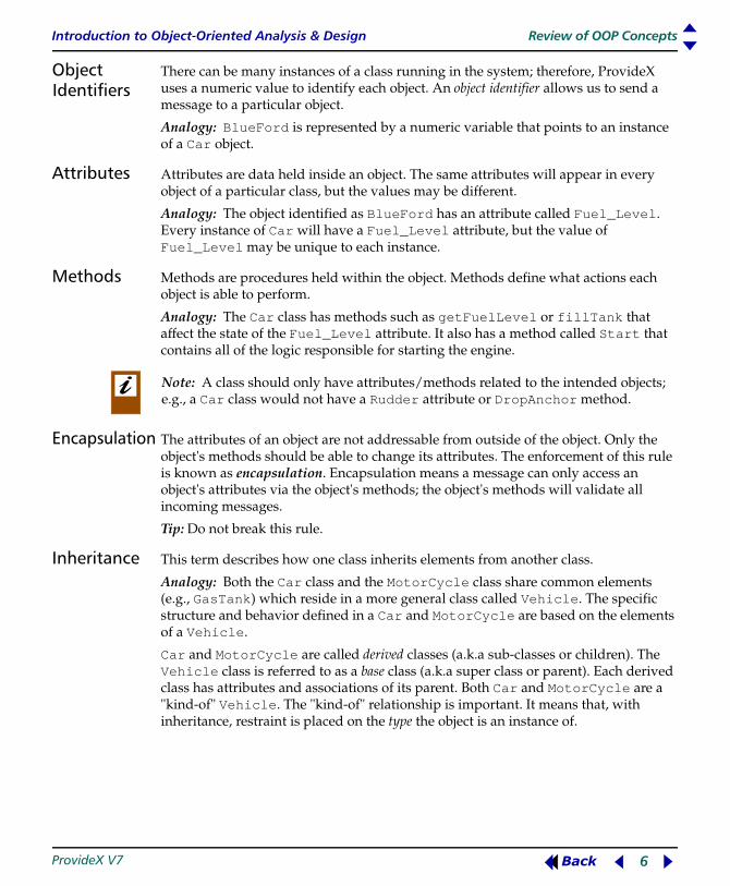
Distinguishing Between an Object and a Class.It is essential to understand the difference between an object and a class. An object is a unique instance of a particular type, whereas the class is that type; e.g.,
Question: Can any of the above objects be a class? Tip: Try adding an "S" to the objects. Content is important.
Object Class
Bob’s Bank Account Bank Account
MIT School
Out of control car Car
Bank of Nova Scotia Bank
Introduction to Object-Oriented Analysis & Design Review of OOP Concepts
ProvideX V7 6 Back
Object Identifiers
There can be many instances of a class running in the system; therefore, ProvideX uses a numeric value to identify each object. An object identifier allows us to send a message to a particular object.
Analogy: BlueFord is represented by a numeric variable that points to an instance of a Car object.
Attributes Attributes are data held inside an object. The same attributes will appear in every object of a particular class, but the values may be different.
Analogy: The object identified as BlueFord has an attribute called Fuel_Level. Every instance of Car will have a Fuel_Level attribute, but the value of Fuel_Level may be unique to each instance.
Methods Methods are procedures held within the object. Methods define what actions each object is able to perform.
Analogy: The Car class has methods such as getFuelLevel or fillTank that affect the state of the Fuel_Level attribute. It also has a method called Start that contains all of the logic responsible for starting the engine.
Encapsulation The attributes of an object are not addressable from outside of the object. Only the object's methods should be able to change its attributes. The enforcement of this rule is known as encapsulation. Encapsulation means a message can only access an object's attributes via the object's methods; the object's methods will validate all incoming messages.
Tip: Do not break this rule.
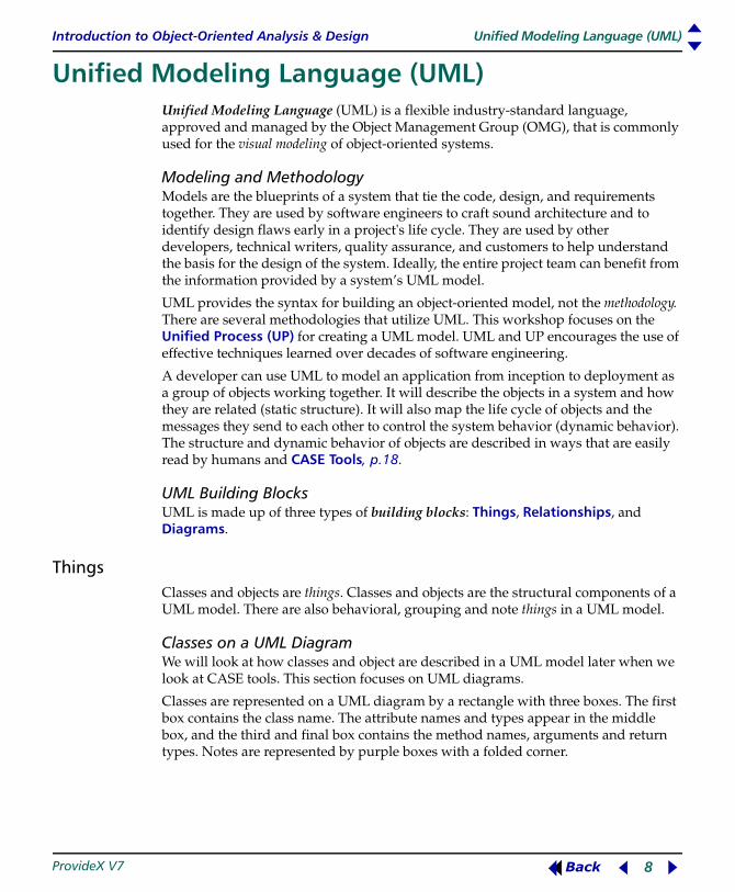
Inheritance This term describes how one class inherits elements from another class.
Analogy: Both the Car class and the MotorCycle class share common elements (e.g., GasTank) which reside in a more general class called Vehicle. The specific structure and behavior defined in a Car and MotorCycle are based on the elements of a Vehicle.
Car and MotorCycle are called derived classes (a.k.a sub-classes or children). The Vehicle class is referred to as a base class (a.k.a super class or parent). Each derived class has attributes and associations of its parent. Both Car and MotorCycle are a "kind-of" Vehicle. The "kind-of" relationship is important. It means that, with inheritance, restraint is placed on the type the object is an instance of.
Note: A class should only have attributes/methods related to the intended objects; e.g., a Car class would not have a Rudder attribute or DropAnchor method.

Introduction to Object-Oriented Analysis & Design Review of OOP Concepts
ProvideX V7 7 Back
Substitutability PrincipleA derived class must be usable through the methods declared in the base class. At anytime the derived class can be substituted for the base class. For example, if a block of code expects to receive a reference to a Vehicle, and instead it receives a reference to a Car, because Car is based on the elements of a Vehicle, the logic will still execute as expected.
Tip: Delegation is an alternative to inheritance. Misuse of inheritance can reduce reusability and complicate maintenance.
Aggregation An aggregate object is an object comprising several other objects, to which it delegates responsibilities. An aggregate forwards messages to attributes that are objects known as delegates. Client objects sending messages to the aggregate are unaware that multiple objects are working behind the scenes. An aggregate delegates responsibilities like inheritance but without the "kind-of" restraints of inheritance.
Collections A collection is an object that groups multiple objects into a single unit. Collections are used to store, retrieve, and transmit objects from one method to another. They don't manipulate the objects, but simply store and retrieve their object identifiers. Collections typically hold objects that form an expected group.
Analogy: A DealerShip object has a collection of Car objects, whereas a ParkingLot has a collection of Vehicle objects.
ProvideX collection objects are *OBJ/COLLECTION and *OBJ/HASHCOLLECTION.
Polymorphism
Polymorphism is based on a Greek word meaning "many forms". In object-oriented modeling, it refers to the ability of objects to respond to a particular message in a manner appropriate to the object's class. Polymorphism is common among classes that are derived from a common base class.
Analogy: All objects that are derived from the Vehicle class have a method called Start. If a ParkingLot object were to cycle through its collection of Vehicle objects to call each Start method, the Car objects will execute logic specific to cars, and Motorcycle objects will execute logic specific to motorcycles, and so on. Although the same message was sent to all Vehicle objects, each object responds with a different Start method.
Introduction to Object-Oriented Analysis & Design Unified Modeling Language (UML)
ProvideX V7 8 Back
Unified Modeling Language (UML) B MK
Unified Modeling Language (UML)
Unified Modeling Language (UML) is a flexible industry-standard language, approved and managed by the Object Management Group (OMG), that is commonly used for the visual modeling of object-oriented systems.
Modeling and MethodologyModels are the blueprints of a system that tie the code, design, and requirements together. They are used by software engineers to craft sound architecture and to identify design flaws early in a project's life cycle. They are used by other developers, technical writers, quality assurance, and customers to help understand the basis for the design of the system. Ideally, the entire project team can benefit from the information provided by a system’s UML model.
UML provides the syntax for building an object-oriented model, not the methodology. There are several methodologies that utilize UML. This workshop focuses on the Unified Process (UP) for creating a UML model. UML and UP encourages the use of effective techniques learned over decades of software engineering.
A developer can use UML to model an application from inception to deployment as a group of objects working together. It will describe the objects in a system and how they are related (static structure). It will also map the life cycle of objects and the messages they send to each other to control the system behavior (dynamic behavior). The structure and dynamic behavior of objects are described in ways that are easily read by humans and CASE Tools, p.18.
UML Building BlocksUML is made up of three types of building blocks: Things, Relationships, and Diagrams.
ThingsClasses and objects are things. Classes and objects are the structural components of a UML model. There are also behavioral, grouping and note things in a UML model.
Classes on a UML DiagramWe will look at how classes and object are described in a UML model later when we look at CASE tools. This section focuses on UML diagrams.
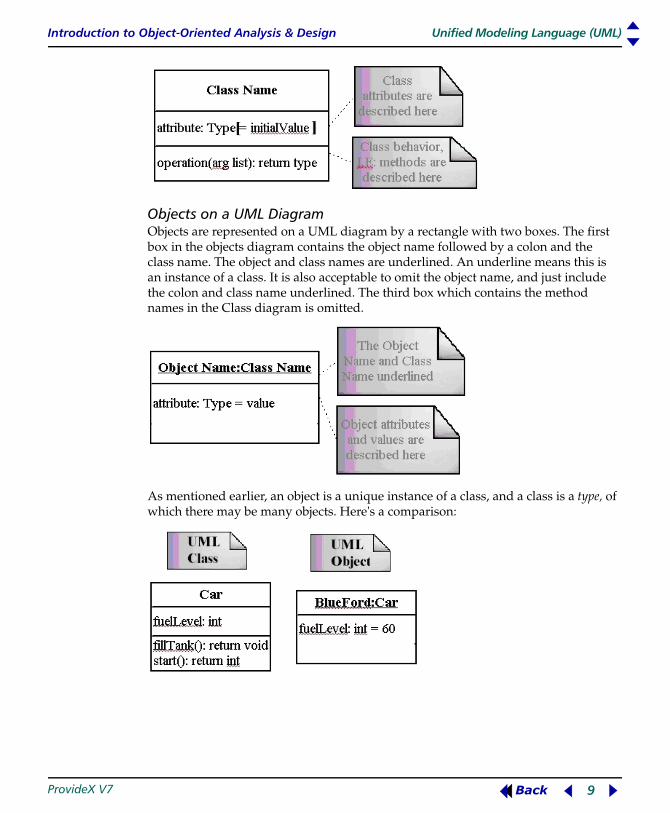
Classes are represented on a UML diagram by a rectangle with three boxes. The first box contains the class name. The attribute names and types appear in the middle box, and the third and final box contains the method names, arguments and return types. Notes are represented by purple boxes with a folded corner.
Introduction to Object-Oriented Analysis & Design Unified Modeling Language (UML)
ProvideX V7 9 Back
Objects on a UML DiagramObjects are represented on a UML diagram by a rectangle with two boxes. The first box in the objects diagram contains the object name followed by a colon and the class name. The object and class names are underlined. An underline means this is an instance of a class. It is also acceptable to omit the object name, and just include the colon and class name underlined. The third box which contains the method names in the Class diagram is omitted.
As mentioned earlier, an object is a unique instance of a class, and a class is a type, of which there may be many objects. Here's a comparison:

Introduction to Object-Oriented Analysis & Design Unified Modeling Language (UML)
ProvideX V7 10 Back
Relationships
Things interact with other things, whereas relationships spell out how things are related to each other. There are four types.
In the example below, the ShoppingCart and Customer classes have an Association relationship. All Associations represent a "has" relationship. The ShoppingCart has 1 Customer object. The Customer has 0 or more ShoppingCart objects. The other relationship demonstrated in this diagram is Generalization. The Customer class has a child called PreferredCustomer; the PreferredCustomer is a "kind-of" Customer.
Association Modelling the potential for links between objects. Associations are drawn as a solid line between two things on a UML diagram. At each end of the line, numeric values indicate how many participants can exist. These values are called multiplicities and will appear on a diagram such as:
"1 -one"* -zero or more (many)"1..* -one or more"0..1 -zero or one
Dependency Modelling what the relationship uses or relies on. Dependency is a potential temporary link, whereas Association indicates the link lasts the lifetime of the object. Dependency is drawn as a dotted line with an unclosed arrow head at one end on a UML diagram.
Generalization The UML equivalent of inheritance. Generalization is drawn as a solid line with an arrow head pointing to the parent thing. The class car is a child of the class vehicle. This relationship is a Generalization.
Realization ........not used in diagrams we're presenting

Introduction to Object-Oriented Analysis & Design Unified Modeling Language (UML)
ProvideX V7 11 Back
Diagrams
These are the graphical representations of UML models. Diagrams present things and relationships found in a UML model in different ways. Think of diagrams as the windows into a UML model. Each type of diagram provides a different perspective of the same underlying model. For example, analysis diagrams visually describe what task a program will perform, and design diagrams describe how the task will be executed. There are nine different types of diagrams in UML. This workshop will concentrate on the five diagrams italicized below:
Example Class Diagram:
Structural Diagrams Behavior Diagrams
Class Use Case
Object Sequence
Component Activity
Deployment Statechart
Collaboration
Introduction to Object-Oriented Analysis & Design Unified Modeling Language (UML)
ProvideX V7 12 Back
SpecificationsDiagrams are not sufficient to describe a UML model. A textual description is also required. A textual description for a thing on a UML diagram is called the specifications. A set of specifications form the semantic backplane of the UML model. The semantic backplane provides context and completes the UML model, by clarifying the structure and behavior of the things in the UML model.
Tip: Create diagrams until a reasonable graphical representation of the system comes into focus, and then add text to the semantic backplane. Some people are diagram-oriented, but others may prefer to have textual descriptions as well.

Introduction to Object-Oriented Analysis & Design Unified Process (UP)
ProvideX V7 13 Back
Unified Process (UP) B MK
U nif ied Proces s (UP)
The Unified Process (UP) is an open software engineering process created by the authors of Unified Modeling Language (UML). It is a modern, light, and adaptive methodology that relies on the use of UML.
UP replaces the Waterfall method of software development. In a Waterfall life cycle, the Requirements and Analysis are completed before Design and Implementation begins. Each phase of development must be accomplished before moving to the next phase. Unfortunately, projects using this method are very slow to get off the ground because they often get bogged down in the first two phases. They are also slow to react when requirements change late in the project's life cycle.
Software development is handled differently under UP, which is essentially a template of the project. The UP methodology generates deliverables throughout each phase of a project's life cycle, and it is able to react quickly to changing requirements. This approach has some obvious benefits:
• Real progress is evident early in the process
• Projects react easily to changing requirements
• Complexity is controlled and developers don't get bogged down in analysis.
Instantiating a UP for projects involves defining standards for documentation, issue tracking, project tracking etc. Best Software Canada Ltd. has been working on various tools to assist in the adaptation of this methodology:
• CASE tool plug-in
• Issues Tracking System
• Integrated Development Environment (IDE).
An in-depth discussion of these tools is beyond the scope of this workshop. This section provides a brief overview of the Unified Process (UP) and how it fits with UML.
Primary UP Features
UP methodology is known for the following distinguishing characteristics:
It is driven by use cases. Each use case is one typical use of a system. For examples of use cases, refer to the section Use Cases and Actors, p.20.
It is architecture-centric. Use cases help create the architecture of the system.
It is an iterative and incremental process. This means it breaks large tasks into smaller more manageable components and makes the system functional in stages. This is how UP projects manage complexity and react quickly to change, while continually generating deliverables. The iterative nature of UP is a key concept.

Introduction to Object-Oriented Analysis & Design Unified Process (UP)
ProvideX V7 14 Back
UP WorkflowsUnder UP, a system is built one use case at a time, and each use case passes through five different workflows. Workflows specify what needs to be done and what skill sets are required to do the work. They include:
We will be illustrating how each of these workflows are applied, using the example of ACME Warehouse Packing Station, p.19.
Project life cycleA project's life cycle is divided into Inception, Elaboration, Construction, and Transition phases. Use cases may pass through each of the five workflows several times throughout the life cycle of a project. This is why we say UP is iterative. After one or more iterations, each use case moves through each phase from Inception to Transition. The following illustrates the five workflows in relation to the life cycle (phases) of a UP project:
This illustration clearly defines the focus of a life cycle. The workshop (and this document) will be describing the area in the highlighted box.
Inception PhaseAs shown by the illustration, most of the work in this phase is handled within the Requirements workflow. At this point, the following is performed:
The scope of any project should be clear by the end of the Inception phase.
Requirements Determine what needs to be done.Analysis Refine requirements and outline system structure.Design Realize the requirements of a use case.Implementation Write the code.Test Confirm that the implementation works.
Requirements Identify purpose of system and what users will expect from it.Analysis Discuss tentative architecture.Design Check feasibility of possible solutions by writing a small
amount of code.

Introduction to Object-Oriented Analysis & Design Unified Process (UP)
ProvideX V7 15 Back
Elaboration PhaseIn the Elaboration phase, we continue to gather Requirements and specify most of the use cases that the system will require:
By the end of this phase, a baseline system should be up and running and the time and resources required to complete the system should be evident.
Construction PhaseHere, the emphasis is on Design and Implementation:
A beta release of the product should be available by the end of this phase.
Transition PhaseDuring the final phase more beta releases lead to bug fixes and finally a general release. After this, a maintenance team and process will be established.
Requirements Specify most use cases in detail.Analysis Determine what needs to be built.Design Finalize the system's architecture.Implementation Write code for critical use cases, and run baseline system.
Requirements Survey use cases to make sure that nothing is missed.Analysis Complete the analysis model.Design Complete the design model.Implementation Construct the system.Test Test to correct any Implementation errors.

Introduction to Object-Oriented Analysis & Design Design Patterns
ProvideX V7 16 Back
Design Patterns B MK
Design Pat terns
A well-designed application should meet its requirements but it should also be adaptable, so that when the real-world requirements change, it can be adapted with minimal effort. In this workshop, we will be using design patterns in our Design Workflow. These concepts are explained below.
What are They?
In 1994, four computer scientists (Erich Gamma, Richard Helm, Ralph Johnson, and John Vlissides) authored a ground-breaking book entitled "Design Patterns: Elements of Reusable Object-Oriented Software." In this book, the authors (aka "the Gang of Four" or "GoF") assert that all of the design problems a software engineer faces have been identified and solved. The GoF identify twenty three different patterns, which can be divided into three groups:
Creational Patterns for object creationStructural Patterns for the structure and composition of classes Behavioral Patterns for the interactions between classes
Essentially, design patterns are recurring design solutions that may be applied to specific problems. A typical design pattern involves three or more classes. Some patterns are simple and obvious, some are complex and elegant.
Patterns can help software engineers resolve common software problems in a tried-and-true way. A development team that has adapted patterns can easily communicate the intention of their code – it becomes somewhat self-explanatory.
For example, when a developer who is familiar with design patterns encounters an Observer (behavioral pattern) in a program, he or she will not have to wade through the code to determine what it does. The pattern is often easily identified by the naming conventions used in the code, as well as by the intent of the pattern and by the way it works as a known commodity.
Don't confuse design patterns with algorithms or language idioms. A design pattern is a solution that can be applied to a design problem in any object-oriented language. In fact, you are probably using patterns already and may not know it.

Introduction to Object-Oriented Analysis & Design Design Patterns
ProvideX V7 17 Back
The following are the design patterns identified in the original GoF design patterns book. This workshop will be applying the patterns in italics.
All design patterns have four characteristics.
Name A name that communicates the use of the patternProblem The problem the pattern will solveSolution The elements and relationships that comprise the patternConsequences The benefits and costs of the pattern
This workshop will be applying the Builder, Singleton, Proxy, and Iterator patterns. For examples, refer to Applying Design Patterns, p.31.
Creational Structural Behavioral
Factory Method(class scope)Abstract FactoryBuilderPrototypeSingleton
Adapter(class scope)AdapterBridgeCompositeDecoratorFaçadeFlyweightProxy
Interpreter(class scope)Chain of ResponsibilityCommandIteratorMediatorMementoObserverStateStrategyVisitor
Note: There are also some patterns in common use that do not appear in the list published by the GoF.

Introduction to Object-Oriented Analysis & Design CASE Tools
ProvideX V7 18 Back
CASE Tools B MK
Case Tools
Computer Aided Software Engineering (CASE) tools are visual modeling aids that allow software engineers to model a system before coding it. With CASE tools, software engineers can identify design flaws early in a project's life cycle, and craft a sound architecture.
These tools are not limited to developers only; in fact, an entire project team can use a CASE tool to extract the information they need from a UML model.
There are several commercial and open source CASE tools available. An internet search should reveal hundreds of CASE tools from different vendors, including:
IBM Rational Rose http://www-306.ibm.com/software/rational/Borland Together http://www.borland.com/together/ArgoUML (free) http://argouml.tigris.orgPoseidon for UML (affordable) http://www.gentleware.com
While UML diagrams can be generated with a simple drawing program like SmartDraw, there are several advantages when creating diagrams with CASE tools:
• They enforce UML syntax
• Model, diagrams and documentation are tied together
• Many CASE tools generate stub code in different programming languages.
XMI and the ProvideX XMI Conversion Tool
XMI is a standard from the Object Management Group (OMG) that defines how an XML file can represent a UML model. XMI is the industry standard way of transferring the contents of a UML model. Most CASE tools can export all of the information contained in a UML model to an XMI file.
The ProvideX XMI Conversion Tool will parse an XMI file and create ProvideX source code. This is extremely valuable. Not only does this tool reduce the time required to write a ProvideX application, but it also ensures the ProvideX code is synchronized with the project's UML model.
For a tutorial on the ProvideX XMI conversion tool, refer to the section Generating Source Code with the ProvideX XMI Conversion Tool, p.53.
Introduction to Object-Oriented Analysis & Design Requirements Workflow
ProvideX V7 19 Back
Requirements Workflow B MK
Requirement s
In this section, we create a requirements model involving a packing station module that is to be added to a hypothetical warehouse management software package. We will be using the tools and methodologies that were described earlier.
Identifying the Requirements
This workshop focuses on object-oriented design and implementation, but we can't start designing until we establish what we intend to build. The first step is to identify the system requirements and generate a requirements model.
The model should clearly communicate the client's needs, and what a system should do in a way that can be understood by end users, software engineers, support/QA staff, and customer service. It should contain enough detail to answer questions from the entire development team and the client's staff.
Most of the work on the requirements model is taken care of during the Inception and Elaboration phases of a UP Project life cycle, p.14. The model is normally generated in the following steps:
1. Identify initial use cases.2. Identify actors.3. Refine the use case model.4. Describe user interfaces.5. Generate domain object model.
ACME Warehouse Packing StationACME has identified a gap in their warehouse management software. Management has found that, from the time a "packing slip" is generated to the time a box is shipped, they have no idea on the status of a package.
Sending a product to customers is a laborious task. The entire process from picking, packing, shipping, and invoicing requires many steps by many people. Inventory is only updated after an item has been shipped and invoiced. As a result, items that appear to be "in stock" when customer service is taking an order may already be (or in the process of being) picked, packaged, shipped or invoiced. Such picking mistakes occur frequently and have proven very costly, especially during peak shipping seasons.
To resolve this problem, management has suggested changes to the shipping process. The addition of a packing station equipped with a PC connected to the warehouse management software will resolve a number of issues:
• Customer service will be able to better track the progress of an order as it moves through the warehouse.
Introduction to Object-Oriented Analysis & Design Requirements Workflow
ProvideX V7 20 Back
• The Packing Station module will update the sales order's shipped quantities with the confirmed packed quantities, which eliminates the need for invoice data entry and improves the accuracy of inventory control.
Manual data entry of shipped and back-ordered quantities during the invoicing process will be eliminated. This will dramatically reduce customer claims and returns through improved picking and packing accuracy.
Use Cases and ActorsWhat are the use cases? As mentioned earlier, a use case represents one standard use of the system. Think of a use case as any task the user would expect to accomplish using the system. Use cases are generated by interviewing end users and customers. They represent the user's perspective of what the system should do. The modeling process is driven by use cases because clients often describe what they want the system to do rather than how the system should do it.
What are the actors? Actors interact with use cases by initiating a series of expected events. An actors typically represents the role a worker would play when interacting with the system. It can be any entity outside of the system that initiates a series of events. For example, a timer that stimulates the system periodically is an actor.
For the packing station, the use cases and actors may be described as follows:
• A warehouse clerk picks and packs all of the items on a sales order's picking slip from the warehouse shelves.
• The items are picked and placed on a cart that is rolled to the packing station.
• The clerk enters the box number and sales order number into the packing station's touch screen.
• The clerk then scans each item with a bar code reader as it is added to the box.
• When each item is scanned, the system decrements the item inventory and increments the sales order's shipped quantities.
• When every item on the cart has been added to the box the clerk presses a button on the touch screen to generate an invoice.
Use Case DiagramIn a use case diagram, the system boundary is drawn as a box labeled with the system's name. Actors are drawn as stick people outside the system, and use cases are drawn as a circle inside the system.

Introduction to Object-Oriented Analysis & Design Requirements Workflow
ProvideX V7 21 Back
The following diagram shows an example Packing Station System, three use cases and two actors. (In a real-world system, there would probably be more use cases.)
Refining the ModelAfter basic use cases and a rough sequence of events have been identified, it is important to refine the model. Refining the requirements model involves identification of use cases that are common among actors and other use cases. The <<include>>, Generalization, and <<extend>> relationships (aka dependencies) are included in the refined use case.
<<include>>In the previous diagram, the clerk must log in prior to packing a box. This means the use case login_to_packing_station is required for the use case Pack_a_box. This is also true for the Customer_service agent; a Customer_service agent can't get the status of an order without logging in. The <<include>> relationship is drawn on a use case diagram as a dotted line with an arrow head. Use <<include>> to consolidate common use cases into one separate use case.
GeneralizationGeneralization (aka inheritance) is drawn in a use case diagram the same way it is drawn in a Class diagram (see Diagrams, p.11). Like classes, use cases and actors can be children or parents of other use cases and actors.

Introduction to Object-Oriented Analysis & Design Requirements Workflow
ProvideX V7 22 Back
In the Packing Station System, it would be useful to allow customers to check the status of their orders without the assistance of a customer service representative. This would require adding another actor called Customer to the use case diagram, and the Customer actor would require a link to the Get_status_of_order use case.
The Customer_Service actor and Customer actor would then share some common behavior; the Customer_Service actor and the Customer actor would both be able to check the status of an order. When multiple entities share common behavior it often makes sense to use generalization and group the common behavior in a base entity.
The Customer_Service and Customer actors could be derived from a more general (base) actor – we use the Purchaser actor in the diagram below. The Purchaser actor is a more general actor from which the Customer_Service and Customer are now derived. The Purchaser actor can log into the system and check the status of an order.
We have also added another use case called Cancel_Order to the diagram. The Cancel_Order use case can only be accessed by the Customer_service actor.
<<extend>>The <<extend>> relationship is a Generalization where an extending use case continues the behavior of a base use case.
Flow-of-EventsThe final step in refining the use case model is to write a detailed textual description of each use case. The following is a detailed description of the Pack_a_box use case:
Use case: Pack_a_boxInitiating Actor: ClerkPreconditions: A customer service representative has created a sales order that contains the customer and the order information. A clerk picks and packs all of the items on the Sales Order's picking slip from the warehouse shelves. The items are picked and placed on a cart that is rolled to a Packing Station.

Introduction to Object-Oriented Analysis & Design Requirements Workflow
ProvideX V7 23 Back
Primary Sequence: 1. Using the Packing Machine's touch screen, the clerk will log into the Packing
Station System.
2. The clerk enters the Sales Order number into the Packing Machine's touch screen.
3. The clerk scans each item with the Packing Machine's bar code reader as it is added to the Box. After each item is scanned, the system decrements the Item in Inventory and increments the Sales Order's packed quantities.
4. When every item on the cart has been added to the Box, the clerk will press a done button on the Packing Machine's touch screen and the system prints the Sales Order's invoice.
Final Steps
At this point, the requirements model is essentially complete. In some instances it may be desirable to create domain object models and business models, but that is beyond the scope of this workshop.
The only thing left to do is create a rough mock-up of the user interface. This can be done using NOMADS and a paint program. Create the GUI using the NOMADS Designer, enter Ctlr-Alt-PrtScn to copy an image of the GUI into a paint program, then save the image to disk for use in your requirements model.

Introduction to Object-Oriented Analysis & Design Analysis Workflow
ProvideX V7 24 Back
Analysis Workflow B MK
Analys is
While the Requirements Workflow provides an end user’s external view of a system, the analysis model expands on the requirements and describes the system in the terminology of a software developer. The analysis model is an internal and external view of the system that describes the structure of the system using classes and use case realizations.
Most of the work on the analysis model is done during the Inception and Elaboration phases of a UP Project life cycle, p.14.
Use Case RealizationThe goal of object-oriented analysis is to deliver use case realizations. The analysis use case realization is essentially a model that contains behavioral and structural diagrams. Structural diagrams are the Class diagrams, and behavioral diagrams are the Collaboration or Sequence diagrams (see Diagrams, p.11 and Design Patterns, p.16). We normally deliver these diagrams in the following steps:
1. Identify and classify classes in each use case.2. Create a rough "first draft" Class diagram.3. Produce a detailed Collaboration diagram.4. Draw on the Collaboration and first draft Class diagrams to produce a detailed
analysis Class diagram.5. Use case refinement.
Identifying and Classifying Classes
Analysis classes should reflect the client's real-world business objects and provide an uncomplicated workable structure that can be elaborated on in the design phase. It is crucial the classes identified during analysis are not inspired by design considerations.
The analysis classes only contain the class name, attributes and associations. Methods are not included on analysis classes.
Identifying Classes using the Noun-Verb MethodThe noun-verb method for identifying classes entails highlighting all of the nouns and verbs in the use case description. Nouns (and noun phrases) are possible classes or attributes. Verbs indicate tasks that a class may be responsible for.
The following primary sequence used in the following example, is taken from the detailed description of the Pack_a_box use case, which was described under Flow-of-Events, p.22. Relevant nouns identifying classes are underlined in red (first instance only). Corresponding verbs are double-underlined in green (first instance only).

Introduction to Object-Oriented Analysis & Design Analysis Workflow
ProvideX V7 25 Back
Primary Sequence: 1. Using Packing Machine's touch screen, the clerk will log into the Packing
Station System.
2. The clerk enters the Sales Order number into the Packing Machine's touch screen.
3. The clerk scans each item with the Packing Machine's bar code reader as he adds it to the box. After each item is scanned, the system decrements the item in inventory and increments the Sales Order's packed quantities.
4. When every item on the cart has been added to the box, the clerk presses a done button on the Packing Machine's touch screen and the Packing Station system prints the Sales Order invoice.
The clerk is an actor, so the noun "clerk" is not highlighted and therefore, not included in the analysis classes. Identifying relevant nouns (classes) and eliminating nouns that are outside of the boundaries of the system can be a difficult task. The clerk, the cart, and the warehouse shelves could all be classes; however, since they are outside of the boundaries of the Packing Station System, they would not be included in the analysis model.
We have now identified several possible classes and attributes and the responsibilities for each. The following classes and attributes have been identified:
Along with noun/verb analysis of the use case description it may be necessary to draw from the physical objects found in the real world. For example, paperwork like the clients existing invoices, orders, receipts, etc, will often help to fill in the details of an identified class. But it is important to remember the business may be looking to replace an obsolete process that has evolved over time. Don't design an OO system that replicates a process that may be broken to begin with.
Touch Screen: ButtonsBar Code Reader: Item ScannedPacking Machine: Touch Screen
Bar Code ReaderPacking Station System: Decrements inventory
Increments Sale's Order's packed quantitiesGenerates an invoiceUser login/logoff
Box: NumberItem:Sales Order: Number
Packed QuantitiesInvoice
Invoice:Inventory: Item

Introduction to Object-Oriented Analysis & Design Analysis Workflow
ProvideX V7 26 Back
Classifying ClassesThe Unified Process specifies three types of analysis classes:
1. Entity (data)• Contain data and methods to manipulate the data• Persist beyond the life span of the use case.
2. Boundary (UI)• Provide user interface • Fire events or send messages to the system based on user interactions• Provide feedback to the user; update the user on the state of the system• Not modeled in detail during analysis. It is important to omit platform specifics.
3. Control• Creates objects and control the sequence of events and message that flow
between objects• Typically exist only for the life span of the use case.
The classes can be classified as follows:
We have now identified and classified analysis classes. We have the noun/verb analysis above and additional resources, so we can now bring it all together in a CASE tool and create a draft of the Class diagram.
Rough Draft The rough Class diagram might look something like the diagram below. In this diagram, the class name identified above as Packing Station System has been shortened to PackingControl, and Packing Machine has been shortened to PackingUI.
Boundary Control Entity
Touch Screen Bar Code ReaderPacking Machine(UI)
Packing Station System BoxItemSales OrderInventoryInvoice
Introduction to Object-Oriented Analysis & Design Analysis Workflow
ProvideX V7 27 Back
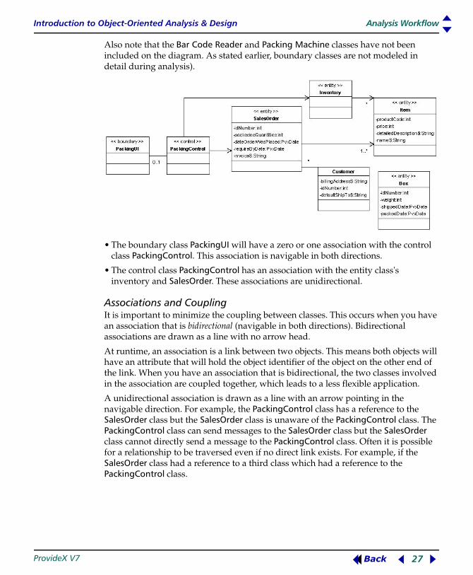
Also note that the Bar Code Reader and Packing Machine classes have not been included on the diagram. As stated earlier, boundary classes are not modeled in detail during analysis).
• The boundary class PackingUI will have a zero or one association with the control class PackingControl. This association is navigable in both directions.
• The control class PackingControl has an association with the entity class's inventory and SalesOrder. These associations are unidirectional.
Associations and CouplingIt is important to minimize the coupling between classes. This occurs when you have an association that is bidirectional (navigable in both directions). Bidirectional associations are drawn as a line with no arrow head.
At runtime, an association is a link between two objects. This means both objects will have an attribute that will hold the object identifier of the object on the other end of the link. When you have an association that is bidirectional, the two classes involved in the association are coupled together, which leads to a less flexible application.
A unidirectional association is drawn as a line with an arrow pointing in the navigable direction. For example, the PackingControl class has a reference to the SalesOrder class but the SalesOrder class is unaware of the PackingControl class. The PackingControl class can send messages to the SalesOrder class but the SalesOrder class cannot directly send a message to the PackingControl class. Often it is possible for a relationship to be traversed even if no direct link exists. For example, if the SalesOrder class had a reference to a third class which had a reference to the PackingControl class.

Introduction to Object-Oriented Analysis & Design Analysis Workflow
ProvideX V7 28 Back
Collaboration Diagram
UML Collaboration diagrams demonstrate the communication between objects. Class diagrams show the static structure of the classes and their relationships with each other. Collaboration diagrams show dynamic interactions between instances of the class at runtime. They also show the messages that are passed between objects.
We have identified and classified the analysis classes, created a Class diagram that illustrates the static structure of the analysis classes. At this point, we need to create a Collaboration diagram to identify the interactions between the classes.

Introduction to Object-Oriented Analysis & Design Analysis Workflow
ProvideX V7 29 Back
Analysis Flow-of-Events
This is a description of the Pack_a_box flow-of-events as they are illustrated in the previous Collaboration diagram:
Preconditions: A customer service representative has created a sales order which contains the customer and the order information. A clerk picks and packs all of the items on the Sales Order's picking slip from the warehouse shelves. The items are picked and placed on a cart that is rolled to a Packing Station.
Flow-of-Events: 1. Clerk enters login user name and password into the PackingUI
2. The PackingUI creates a PackingControl object
3. The sales order number is entered
4. The PackingControl object creates a box
5. PackingControl gets the SalesOrder from the sales order list
6. An item's bar code is scanned by the Clerk
7. The PackingControl object is directed to add the item to the box
8. The PackingControl object retrieves the item from inventory
9. The PackingControl object tells the box to add the item
10.The PackingControl object tells the SalesOrder to add the item
11.The PackingControl object informs the inventory the item has been packed - Inventory decrements on-hand quantities of the item
12.The clerk hits Done
13.The PackingControl object is directed to print an invoice
14.The PackingControl object directs the SalesOrder object to generate an invoice
15.The SalesOrder object creates an invoice
16.The PackingControl object directs the InvoicePrinter to print the invoice.
Detailed Analysis Class Diagram
We will be drawing on the first Class diagram and the Collaboration diagram to produce a detailed version of the analysis Class diagram. The Rough Draft outlines general structure and relationships of the classes, and the Collaboration Diagram provides a detailed textual description of the sequence of events that flow between the objects.
With this information combined we can now complete the final analysis Class diagram, which is necessary for use case realization.

Introduction to Object-Oriented Analysis & Design Analysis Workflow
ProvideX V7 30 Back
Final Steps
Lastly, we complete the Analysis model by refining the use cases, and documenting the classes and attributes discovered.
During the analysis process, it is possible to find new information that should have appeared in the original use case. For example, the original use case indicates an invoice should be generated but it did not provide enough detail – should the invoice be printed? If the invoice is supposed to be printed, then where should it be printed?
All models require a textual description as well as diagrams. To complete the analysis model, document the diagram's attributes and classes.

Introduction to Object-Oriented Analysis & Design Design Workflow
ProvideX V7 31 Back
Design Workflow B MK
Design
In the Analysis Workflow, we describe the system in an abstract way. In the design model, we expand on the analysis and provide a detailed blueprint for the system.
The design process determines how the functionality outlined in the analysis model will be realized. The analysis model is provisional, whereas the design model serves as the primary documentation of the product and it is continually updated as changes are required throughout the life of a product.
Most of the work on the design model is done during Elaboration and Construction phases of a UP Project life cycle, p.14. The goal in the design model is to deliver design use case realizations. When complete, it should contain the following:
1. Designing classes (detailed and refined from analysis)2. Interfaces. Not applicable at this time (see note below)3. Designing use case realizations.
Applying Design PatternsA well-designed application should meet its requirements but it should also be flexible, so that when the real-world requirements change, it can be adapted with minimal effort. This is why the design workflow can be one of the most difficult to complete – an adaptable and reusable object-oriented design requires an especially cohesive approach. In this section, we will be applying techniques known as design patterns (the Builder Pattern, the Singleton Pattern, and the Proxy Pattern). For more on these concepts, refer to Design Patterns, p.16.
Use Case RealizationThe design model further refines the analysis model. The design use case realization is essentially a model comprising behavioral and structural diagrams. The structural diagrams are detailed Class diagrams and the behavioral diagrams are Sequence diagrams, which may also include Collaborations and Statecharts (see Diagrams, p.11). We will deliver these diagrams and a textual description of the flow-of-events between classes in the following steps:
1. Create design classes by refining analysis Class diagram and adding:• Methods and method parameters• Visibility of class methods and attributes• life cycle of classes• Detailed relationships (e.g., inheritance and aggregation).
2. Identify and specify interfaces. Not applicable at this time (see previous note).
3. Produce design use case realization by creating detailed class and Sequence diagrams.
4. Create a Deployment diagram from the use case realizations.
Note: An interface is a class that has defined methods that are only implemented through inheritance. Classes that inherit from an interface must implement all methods belonging to that interface. ProvideX OOP directives do not support this functionality at this time.

Introduction to Object-Oriented Analysis & Design Design Workflow
ProvideX V7 32 Back
Remember, UP is incremental and iterative. Steps 1 through 4 above will likely be repeated several times in order to complete the design. The first pass identifies class methods, defines each method's parameters, and returns; another pass would refine the associations (navigability, collections, etc) ... and so on.
Designing ClassesIn the design model, the classes come from two sources: the problem domain and the solution domain (described in the section Design Patterns, p.16). The problem domain is the analysis model, whereas the solution domain consists of third party libraries, utility classes, component frameworks like COM, and so on. Often, classes defined in the analysis model will be divided into several classes in the design model.
The source code can be generated directly from the design model; therefore, it is important that the following be achieved:
1. Classes must be complete and able to meet requirements.
2. Methods should be primitive. This means that one method provides one service – multiple methods should not be accomplishing the same task.
3. The classes that make up a system should be cohesive. Every class should serve one specific purpose. If a class has several responsibilities, then "helper" classes should be created, and the class should delegate responsibilities to the "helper". It is crucial that every class is focused on one objective and its attributes, methods and associations are all geared to accomplish just one task. Cohesion provides:• Simple classes that are easily understood• Reusable classes• A more adaptable and maintainable system
4. The classes in the model must not be tightly coupled. It is important to get the balance right when modeling relationships between classes. The goal is to have objects within a system interacting to complete a task; however, a class should only have a reference to another class when absolutely necessary in order to fulfill its responsibilities.
Overly-coupled classes are usually created by novice developers who do not employ sound project management techniques and allow a system to evolve in a more-or-less uncontrolled way. This sort of coupling is the object-oriented equivalent of "spaghetti code" and it leads to a system filled with classes that are not maintainable or reusable. This is probably the most common mistake made by novice developers in object-oriented programming.
Avoiding PitfallsAs mentioned above, coupling must be avoided. The overuse of inheritance is the worst kind of coupling, and it leads to less flexible and reusable classes. The other problem with inheritance is the "fragile base class" problem. This occurs when changes made to a base class impacts the functionality of many derived classes spread throughout the system.

Introduction to Object-Oriented Analysis & Design Design Workflow
ProvideX V7 33 Back
Inheritance should only be used when you require some of the implementation details of the parent class; i.e, the methods, attributes or links between other objects. One alternative to inheritance from another class, is inheritance from an interface (aka black box reuse). This type of inheritance provides greater flexibility because it allows you to determine what functionality an object provides without putting restraints on what that object is. However, ProvideX does not support interfaces at this time.
The other alternative to inheritance is delegation. A class will often be composed of other classes; this relationship between classes is called aggregation or composition (a stronger form of aggregation). For example, class "A" requires some functionality class "B" provides. Class "A" could extend class "B" (ProvideX LIKE directive) or class "A" can declare class "B" as a local attribute and call class "B" methods as required.
Refining the Analysis Class DiagramThe following diagram refines the associations of the analysis Class diagram.
At design time, associations are called links. The diagram above contains all of the classes, and all of the links between the classes, required to meet the requirements of the Pack_a_box use case.

Introduction to Object-Oriented Analysis & Design Design Workflow
ProvideX V7 34 Back
The classes diagramed above are not complete; they do not contain the methods required to complete the Pack_a_box use case. As mentioned, Class diagrams are structural diagrams that illustrate the static structure and links between classes. To determine the methods required to implement the use case, we need to create a behavioral diagram.
Sequence DiagramDuring analysis, we used a Collaboration Diagram to determine the interactions between objects. The better behavioral diagram to use for design is a Sequence diagram. A Sequence diagram does more than show interactions between objects over time, it maps the events and messages that pass between objects over time and it shows the life cycle of objects. It points out the methods each object requires.
Furthermore, they help us understand the dynamic behavior of a system. Developers often focus on the static structural relationships of classes and do not examine the dynamic runtime behavior of the classes until they start to write code. You cannot create an effective design without a complete static and dynamic model.
Excessive use of coupling is a hallmark of object-oriented system design that ignores the dynamic nature of the application. Allen Holub summarized the importance of Sequence diagrams like this:
"Without a clearly defined dynamic model, you're only guessing how you will use a class's objects. Consequently, accessor methods often wind up in the model because you must provide as much access as possible since you can't predict whether or not you'll need it. This sort of design-by-guessing strategy is inefficient at best. You waste time writing useless methods (or adding unnecessary capabilities to the classes)." Taken from the article "Why getter and setter methods are evil".

Introduction to Object-Oriented Analysis & Design Design Workflow
ProvideX V7 35 Back
A Sequence diagram outlines the methods required by each class; e.g.,
We can determine from a Sequence diagram what methods will be required to complete the Pack_a_box use case described below.
Design Flow-of-Events
This is a description of the Pack_a_box flow-of-events as illustrated in the previous Sequence diagram.
Preconditions: A customer service representative has created a sales order which contains the customer and the order information. A clerk picks and packs all of the items on the sales order's picking slip from the warehouse shelves. The items are picked and placed on a cart that is rolled to a Packing Station.
Flow-of-Events:
1. 1Clerk enters login user name and password into the PackingUI
2. PackingControl = new PackingControl( )
3. PackingControl'enterSalesOrder(orderNumb$)
4. Box = new Box( )
5. SalesOrder = SalesOrderList'getSalesOrder(orderNumb$, box)
6. WHILE isClerkScanning( );
7. PackingUI'obtainBarCode
8. The packingControl'packItem(barcode)
9. Item = Inventor'getItem(barCode$)

Introduction to Object-Oriented Analysis & Design Design Workflow
ProvideX V7 36 Back
10. Box'addItem(item)
11. END WHILE (clerk hit done button)
12. PackingControl'printInvoice( )
13. Invoice = SalesOrder'getPrintableInvoice( )
14. Invoice = new Invoice( )
15. InvoicePrinter = new InvoicePrinter( )
16. InvoicePrint'printInvoice(invoice)
17. DropInvoicePrinter( )
18. DropPackingControl( )
With the methods identified we can now add most of the required methods to the Class diagram, below. The following Class diagram shows a couple of changes. The methods outlined in the Sequence diagram have been added. The Sequence diagram also showed that the PackingControl class does not call methods in the PackingUI class; therefore, we have made the link between PackingControl and PackingUI not navigable by PackingControl (an arrow head now appears at PackingControl end of link).

Introduction to Object-Oriented Analysis & Design Design Workflow
ProvideX V7 37 Back
The current design creates and destroys the required objects, and most of the methods required by each object have been identified. However, the design is not complete. The behavioral diagram has shown the current design falls short of accomplishing the Pack_a_box use case. This is because it does not specify how the Invoice and InvoicePrinter objects will communicate allowing the PackingControl object to print the invoice. To print an invoice, the design must accomplish the following:
1. SalesOrder passes the salesOrderNumber to the invoice
2. SalesOrder provides the invoice with a list of items that have been packed in the box
3. SalesOrder provides the invoice with the Purchaser's customerName$, and billingAddress$ attribute values
4. The invoice retrieves each item's name$, detailedDescription, and price attributes
5. The InvoicePrinter formats and prints the information contained in the invoice.
The above tasks could be accomplished by adding a few links between each class and several accessor methods, but this would be an inelegant solution. Too many links between classes leads to coupling, which is undesirable. Accessor methods, which are methods used to examine or modify the members of a class, often expose too much detail about the implementation of an object.
As mentioned earlier, a good design must produce primitive and cohesive classes. Information must flow between classes without coupling or exposing the implementation details of the classes. We require a design solution so this is an ideal situation to apply design patterns.
Builder Pattern
The builder design pattern is a creational design pattern, specifically a type of Factory. A Factory is a class that constructs other objects of different types. Creating objects via a Factory facilitates adaptation. For example, using a Builder to generate our invoice would allow us to add the ability to generate an invoice in different formats like PDF, JPEG, etc. Using the builder also minimizes coupling and the need for accessor methods.
Introduction to Object-Oriented Analysis & Design Design Workflow
ProvideX V7 38 Back
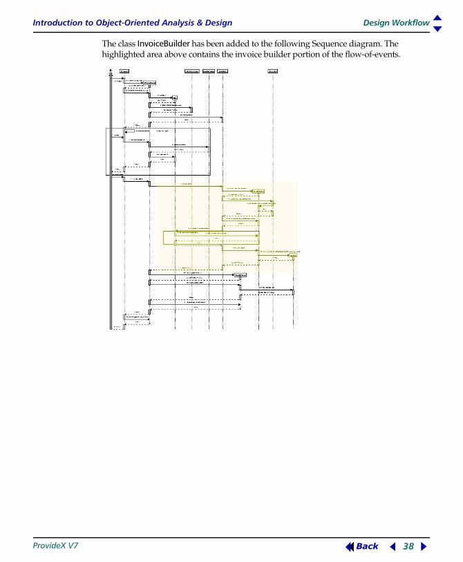
The class InvoiceBuilder has been added to the following Sequence diagram. The highlighted area above contains the invoice builder portion of the flow-of-events.

Introduction to Object-Oriented Analysis & Design Design Workflow
ProvideX V7 39 Back
Following is a closer look at the invoice builder portion:
Builder and Invoice Flow-of-Events This is a description of the flow-of-events illustrated in the previous diagram.
Preconditions: A customer service representative has created a sales order which contains the customer and the order information. A clerk picks and packs all of the items on the sales order's picking slip from the warehouse shelves. The items are picked and placed on a cart that is rolled to a Packing Station.
The Clerk has scanned and added all of the items to the box and hit done to print an invoice; the system has completed events 1 through to 12 outlined in the above diagram.
Flow-of-Events: 1. 1SalesOrder calls Purchaser's exportCustomer method and passes the
invoiceBuilder: purchaser'exportCustomer(invoiceBuilder)
2. Purchaser class calls the invoiceBuilder's addCustomer method to add the customer's information to the invoiceBuilder
3. SalesOrder calls invoiceBuilder'addSalesOrderNumber(orderNumber$) to add the SalesOrder number to the invoiceBuilder
4. SalesOrder calls the Box's exportItems method and passes the invoiceBuilder: box'exportItems(invoiceBuilder)
5. WHILE boxHasMoreItems( )
6. The Box calls invoiceBuilder's addItem method for each item in the box
7. END WHILE
8. SalesOrder calls InvoiceBuilder's buildInvoice method
9. InvoiceBuilder instantiates a new invoice

Introduction to Object-Oriented Analysis & Design Design Workflow
ProvideX V7 40 Back
10. PackingControl instantiates an InvoicePrinter; InvoicePrinter = new InvoicePrinter( )
11. PackingControl calls the invoicePrinter's printInvoice method to print the invoice: InvoicePrint'printInvoice(Invoice)
12. InvoicePrinter calls the invoice's getInvoiceBody$( ) method which returns a String that contains the invoice details in text format
13. PackingControl destroys the invoicePrinter; DROP OBJECT InvoicePrinter
14. PackingUI destroys PackingControl; DROP OBJECT PackingControl.
Director and Builder Classes.The Builder pattern is comprised of Director and Builder classes. In the previous example, the Director is the SalesOrder class. It decides what component parts of the invoice is built, and in what order the invoice is built by repeatedly calling methods in the Builder. The Director controls the order and items added to the invoice, but it does not build the invoice. The construction of the invoice is delegated to the Builder.
The Builder class in this example is TextInvoiceBuilder. Classes export data to the Builder object, but they do not pass their fields. Data is added to the Builder as a numeric or string value. TextInvoiceBuilder creates an invoice containing a simple text document.
Different Builders create invoices in different formats. The TextInvoiceBuilder and HTMLInvoiceBuilder are both derived from the base class InvoiceBuilder. The Purchaser and Box classes are only aware they are exporting data to an InvoiceBuilder. In the Pack_a_box use case the clerk requires a printable invoice. Therefore, in the example above, the Director (SalesOrder class) generates a printable invoice by instantiating a TextInvoiceBuilder and directing the Purchaser and the Box to export information to it. The TextInvoiceBuilder builds a simple text document.
If the Director required an invoice viewable in a web browser, it would instantiate an HTMLInvoiceBuilder; e.g., if a customer service representative checking the status of a SalesOrder wished to view an order's invoice in a web browser from a remote location. The invoice format changes completely without affecting the rest of system.
The following code demonstrates how the Text and HTML versions of the InvoiceBuilder's addCustomer methods would be implemented in ProvideX.
TextInvoiceBuilder addCustomer function:FUNCTION addCustomer(name$,billingAddress$)ENTER name$,billingAddress$LET invoiceValue$+=name$+SEP+billingAddress$+SEP
HTMLInvoiceBuilder addCustomer function:FUNCTION addCustomer(name$,billingAddress$)ENTER name$,billingAddress$LET invoiceValue$+="<B>"+name$+"</B><BR>"+billingAddress$+"<BR>...

Introduction to Object-Oriented Analysis & Design Design Workflow
ProvideX V7 41 Back
The following Class diagram refines previous Class diagrams by adding the InvoiceBuilder classes and the methods required to build the invoice.
Information now flows between objects that are not coupled or exposing internal implementation details. The invoiceBuilder object is completely unaware of the objects which are sharing data with it. If the invoiceBuilder called accessor methods in the SalesOrder, Purchaser, and Box objects (or worst yet, directly referenced those object's attributes) the system would be far less adaptable and maintainable. The objects that export data to the builder are also unaware of the exact type of builder.

Introduction to Object-Oriented Analysis & Design Design Workflow
ProvideX V7 42 Back
This means as long as the object that is building the invoice is a child of InvoiceBuilder, the way the invoice is built can change without affecting the client or entity objects involved.
The diagram now contains dependency associations (dotted line with arrow head). As mention earlier (Unified Modeling Language (UML), p.8), a dependency is a way to model the relation "uses" or "relies on". The dependencies illustrated above indicate a temporary link is required during the execution of a method. Solid lines indicate a link that last the lifetime of the object, and therefore an attribute holding an object ID referencing the class at the arrow head end of the association will be declared in the definition of the class.
This is done in ProvideX using the LOCAL or PROPERTY directives within the DEF block of a class; e.g.,
10 DEF CLASS "PackingControl"20 PROPERTY salesOrder
Singleton Pattern
It is often necessary to ensure that only one instance of a particular class exists; e.g., a WindowManager or a FileManager object. The Singleton design pattern is the solution to this design problem. A class that ensures there will never be more than one instance of itself is called a Singleton.
It is possible to create one instance of a class at the beginning of a program and then document that this particular object is the only instance of the class that should exist during the program life cycle. However, the only way to ensure that a single instance of a class exists is to use a Singleton. In ProvideX, a Singleton is implemented using the UNIQUE directive.
Do not overuse the Singleton design pattern. Singletons are equivalent to adding global variables to an object-oriented system.
It should be obvious by now that eliminating unnecessary links between classes and reducing the navigability of links is a big part of refining the design model. Singletons can be used to reduce links between objects. A client object does not need to declare a reference to a singleton because it can get the reference at runtime via the NEW directive.
For example, when Inventory is not a singleton, an object identifier for Inventory is declared as a member variable:
00010 DEF CLASS "PackingControl"00030 ! Associations:00070 PROPERTY Inventory00080 PROPERTY Box
…. Inventory and box initialized
00090 ! Operation: packItem00180 FUNCTION packItem(barCode$)00190 ENTER barCode

Introduction to Object-Oriented Analysis & Design Design Workflow
ProvideX V7 43 Back
00191 LET item=Inventory'getItem(barCode$)00192 Box'addItem(item)...00200 RETURN
When Inventory is a Singleton, an object identifier for Inventory is not required until needed:
00010 DEF CLASS "PackingControl"00030 ! Associations:00080 PROPERTY Box
….Box initialized
00090 ! Operation: packItem00180 FUNCTION packItem(barCode)00190 ENTER barcode00200 Inventory = new ("Inventory") 00210 LET item=Inventory'getItem(barCode)00220 Box'addItem(item)...00230 RETURN
When Inventory is a Singleton there is no need to declare a member variable to hold the Inventory object ID because the state of the inventory object will not change when the function PackItem goes out of scope.
What classes in the Pack_a_box use case should be singletons? Several classes could be Singletons; i.e.,
InvoicePrinterInvoiceBuilder (and children)InventoryPackingUI
The context of the Pack_a_box use case suggests that the InvoicePrinter and Inventory classes should be Singletons. The next diagram illustrates this change to the design model. Note that the stereotype <<singleton>> now appears above the class names in the Inventory and InvoicePrinter classes. Most importantly, notice that the link between PackingControl and Inventory is no longer required, and the link between PackingControl and InvoicePrinter is no longer required.
Introduction to Object-Oriented Analysis & Design Design Workflow
ProvideX V7 44 Back
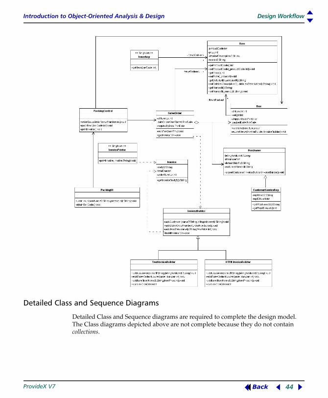
Detailed Class and Sequence Diagrams
Detailed Class and Sequence diagrams are required to complete the design model. The Class diagrams depicted above are not complete because they do not contain collections.

Introduction to Object-Oriented Analysis & Design Design Workflow
ProvideX V7 45 Back
Using CollectionsCollections are implied by the maximum-of-many multiplicity association illustrated by an * asterisk character on a UML diagram. For example, in the previous diagram, the PackingControl class references a maximum-of-many salesOrders. The salesOrder, Box, and Inventory reference maximum-of-many items. Detailed Sequence diagrams must explicitly illustrate the collection objects and classes. The collection classes and their methods must be identified so that the Sequence diagrams can be correctly modeled and collection methods can be documented. Collections are shown on the following Class diagram:

Introduction to Object-Oriented Analysis & Design Design Workflow
ProvideX V7 46 Back
As mentioned earlier (Collections, p.7), ProvideX has two collection objects: *obj/collection and *obj/hashcollection. Both collection objects have been added to the diagram.
*obj/collection usage:The ProvideX group class can store and retrieve one or many object IDs. To add an object to a group:
10 LET Group=NEW("*obj/collection")30 itemIndx=Group'add(NEW("myObject"))
...
Then, retrieve the object from the group:
60 LET myObject=Group'item(itemIndx)...
The Box class holds the list of items that have been packed in a group. The group object id is held in the Box class's itemsPackedList attribute.
The SalesOrder class holds the list of items that have been ordered in a group. The group object id is held in the SalesOrder class's itemsOrderedList attribute.
*obj/hashcollection usage:The ProvideX HashGroup class can store and retrieve one or many object id's with string keys. To add an object to a HashGroup:
10 myObjectKey$ = "a unique key for this object"20 LET hashGroup=NEW("*obj/hashcollection")30 hashGroup'add(myObjectKey$, NEW("myObject"))
...
Then, retrieve the object from the group:
50 LET itemIndx=hashGroup'finditembykey(myObjectKey$)60 LET myObject=hashGroup'item(itemIndx)...
The Inventory class holds the list of items in stock in a HashGroup. The HashGroup object ID is held in the Inventory class's itemsOnHandList attribute. Utilizing the HashGroup class allows the Inventory class to store and retrieved items keyed by a barcode number.
The SalesOrderList class is a singleton that is derived from the HashGroup class. SalesOrderList is derived from the HashGroup class because the system requires a singleton and HashGroup is not a Singleton. The SalesOrderList class does not change the functionality of HashGroup in any other way.
Using collections also allows us to eliminate links between objects. Notice how there is no longer a link from the SalesOrder and Box classes to the Item class. The link between Inventory and Item has also been eliminated.

Introduction to Object-Oriented Analysis & Design Design Workflow
ProvideX V7 47 Back
Note that the Box and SalesOrder class both point to the group class. This does not mean that the SalesOrder and Box classes will point to the same group object at runtime. Remember that this is a Class diagram, not an object diagram. The Sequence diagram below shows the instances of group and HashGroup, and the calls to them (highlighted sections):
Once again, the Sequence diagram has identified the methods each object will require. We can now revisit and refine the Class diagram. At this point the Group and HashGroup methods could be added to the Class diagram. However, they are not required and can be omitted.
As mentioned earlier in this chapter, the design model will contain classes derived from the problem domain and taken from the solution domain. The Group and HashGroup classes are taken from the solution domain. The collection classes should be known to the team programmers and the relationships are not complex. Including the links to these collections and the details of the collection classes may obscure the important relationships that are the focus of the Class diagram. The collection objects

Introduction to Object-Oriented Analysis & Design Design Workflow
ProvideX V7 48 Back
should be included in the Sequence diagrams, but are not required on the Class diagram. Include the collections in the attributes of the client classes instead of illustrating the collection classes and the links to them:
The collection classes have been removed from the Class diagram above and they now appear as attributes within the client classes. The following classes and attributes are of interest:
Class Name Attribute Name Type of Collection
SalesOrderBoxInventorySalesOrderList
itemsOrdereditemsPackeditemsOnHand
GroupGroupHashGroupkind-of HashGroup
Introduction to Object-Oriented Analysis & Design Design Workflow
ProvideX V7 49 Back
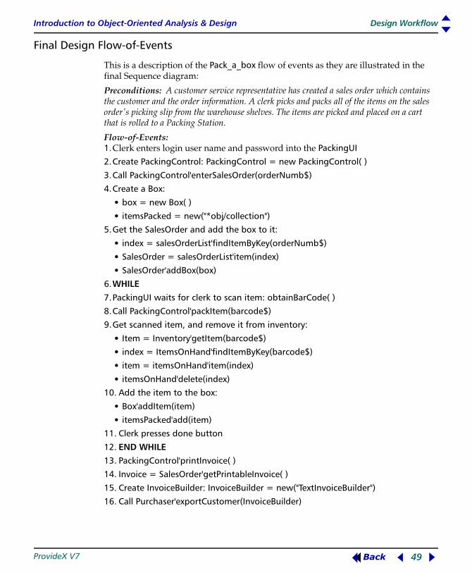
Final Design Flow-of-Events
This is a description of the Pack_a_box flow of events as they are illustrated in the final Sequence diagram:
Preconditions: A customer service representative has created a sales order which contains the customer and the order information. A clerk picks and packs all of the items on the sales order's picking slip from the warehouse shelves. The items are picked and placed on a cart that is rolled to a Packing Station.
Flow-of-Events: 1. 1Clerk enters login user name and password into the PackingUI
2.Create PackingControl: PackingControl = new PackingControl( )
3.Call PackingControl'enterSalesOrder(orderNumb$)
4.Create a Box:
• box = new Box( )
• itemsPacked = new("*obj/collection")
5.Get the SalesOrder and add the box to it:
• index = salesOrderList'findItemByKey(orderNumb$)
• SalesOrder = salesOrderList'item(index)
• SalesOrder'addBox(box)
6.WHILE
7.PackingUI waits for clerk to scan item: obtainBarCode( )
8.Call PackingControl'packItem(barcode$)
9.Get scanned item, and remove it from inventory:
• Item = Inventory'getItem(barcode$)
• index = ItemsOnHand'findItemByKey(barcode$)
• item = itemsOnHand'item(index)
• itemsOnHand'delete(index)
10. Add the item to the box:
• Box'addItem(item)
• itemsPacked'add(item)
11. Clerk presses done button
12. END WHILE
13. PackingControl'printInvoice( )
14. Invoice = SalesOrder'getPrintableInvoice( )
15. Create InvoiceBuilder: InvoiceBuilder = new("TextInvoiceBuilder")
16. Call Purchaser'exportCustomer(InvoiceBuilder)
Introduction to Object-Oriented Analysis & Design Design Workflow
ProvideX V7 50 Back
17. Purchaser's exportCustomer method calls the InvoiceBuilder's addCustomer method, passing customer's name and billingAddress
18. SalesOrder calls the InvoiceBuilder's addSalesOrderNumber method passing the salesOrderNumber
19. SalesOrder calls the box's exportItems method passing the invoiceBuilder
20. FOR each item in the itemsPacked group
21. The box gets the item from the itemsPacked group
22. The box calls the InvoiceBuilder's addItem method passing the item's name and price
23. SalesOrder calls the InvoiceBuilder's buildInvoice method
24. InvoiceBuilder creates a new Invoice object: invoice = new("Invoice", body$, totalDue, orderNumber$)
25. SalesOrder destroys the InvoiceBuilder object: DROP OBJECT InvoiceBuilder
26. PackingControl creates a new InvoicePrinter object: InvoicePrinter = new("InvoicePrinter")
27. PackingControl calls the InvoicePrinter's print invoice method passing the invoice
28. InvoicePrinter call's the Invoice's getBody$() method and prints the returned string
29. PackingControl destroys the InvoicePrinter: DROP OBJECT (InvoicePrinter)
30. PackingControl destroys the Invoice object: DROP OBJECT Invoice
31. PackingUI destroys the PackingControl object: DROP OBJECT PackingControl.
The design could be further refined. Currently, the Inventory object has the attributes itemsOnHand and itemsOutOfStock. The itemsOnHand and itemsOutOfStock objects are hashcollection objects that contain possibly hundreds or thousands of instances of the Item class. This is obviously not the most efficient design.
Proxy Pattern
The Proxy design pattern could be utilized to reduce the memory require by this design. With the Proxy design pattern, the data for each item object would be stored on disk. Instead of holding actual instances of the item class, the hashcollection could contain an instance of a proxy class that is masquerading as an item. The proxy class would then load the information from disk when it was required.
The following Class diagram illustrates the classes that would be involved in the Proxy design pattern:

Introduction to Object-Oriented Analysis & Design Design Workflow
ProvideX V7 51 Back
When the Box object calls one of the item's methods, for example the getPrice( ) method, an ActualItem object would simply return the value of its price variable.
The ProxyItem would contain an attribute called realItem. The realItem attribute would contain the object ID of an Item object. When any of the Item methods are called, the ProxyItem would check if it has a realItem object loaded in memory. If the realItem object ID is not initialized, then ProxyItem would retrieve the ActualItem's information from disk and create the Item (initializing the realItem variable). The Proxy item would then delegate all of the item calls to the realItem object.
At this point, a designer may choose to generate a UML Statechart diagram. A Statechart diagram is a behavioral diagram not covered in this workshop.
Because the UP process is iterative, the design will be revisited several times. This design would be perfected after a couple of iterations.
We have now completed the first iteration of design and we can proceed to write code in the next phase in a UP project life cycle.
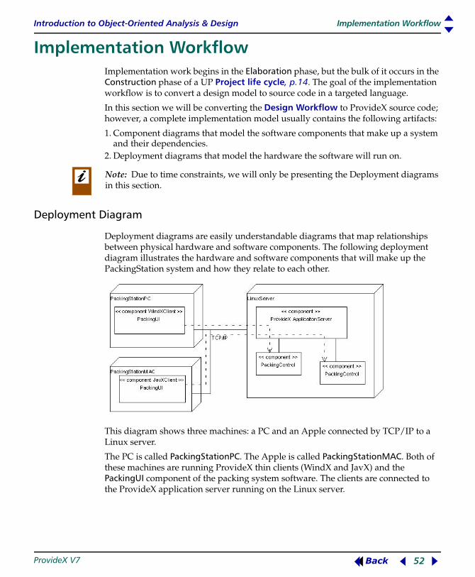
Introduction to Object-Oriented Analysis & Design Implementation Workflow
ProvideX V7 52 Back
Implementation Workflow B MK
Implementation
Implementation work begins in the Elaboration phase, but the bulk of it occurs in the Construction phase of a UP Project life cycle, p.14. The goal of the implementation workflow is to convert a design model to source code in a targeted language.
In this section we will be converting the Design Workflow to ProvideX source code; however, a complete implementation model usually contains the following artifacts:
1. Component diagrams that model the software components that make up a system and their dependencies.
2. Deployment diagrams that model the hardware the software will run on.
Deployment Diagram
Deployment diagrams are easily understandable diagrams that map relationships between physical hardware and software components. The following deployment diagram illustrates the hardware and software components that will make up the PackingStation system and how they relate to each other.
This diagram shows three machines: a PC and an Apple connected by TCP/IP to a Linux server.
The PC is called PackingStationPC. The Apple is called PackingStationMAC. Both of these machines are running ProvideX thin clients (WindX and JavX) and the PackingUI component of the packing system software. The clients are connected to the ProvideX application server running on the Linux server.
Note: Due to time constraints, we will only be presenting the Deployment diagrams in this section.
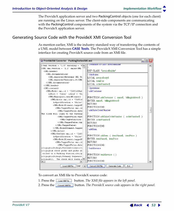
Introduction to Object-Oriented Analysis & Design Implementation Workflow
ProvideX V7 53 Back
The ProvideX application server and two PackingControl objects (one for each client) are running on the Linux server. The client-side components are communicating with the PackingControl components of the system via the TCP/IP connection and the ProvideX application server.
Generating Source Code with the ProvideX XMI Conversion Tool
As mention earlier, XMI is the industry standard way of transferring the contents of a UML model between CASE Tools. The ProvideX XMI Conversion Tool has a simple interface for creating ProvideX source code from an XMI file.
To convert an XMI file to ProvideX source code:
1. Press the button. The XMI file appears in the left panel.2. Press the button. The ProvideX source code appears in the right panel.
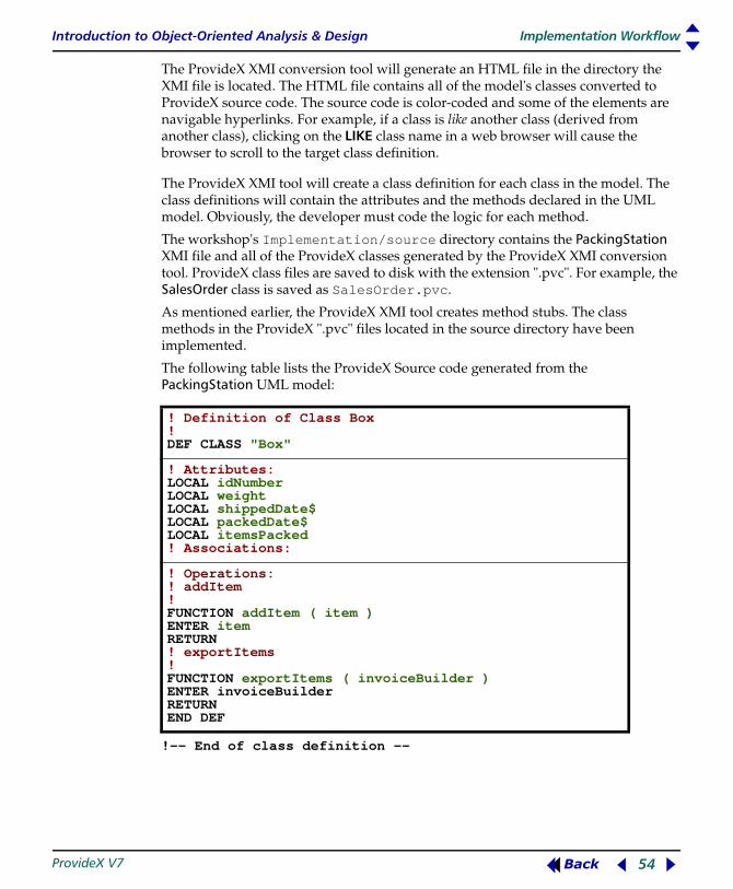
Introduction to Object-Oriented Analysis & Design Implementation Workflow
ProvideX V7 54 Back
The ProvideX XMI conversion tool will generate an HTML file in the directory the XMI file is located. The HTML file contains all of the model's classes converted to ProvideX source code. The source code is color-coded and some of the elements are navigable hyperlinks. For example, if a class is like another class (derived from another class), clicking on the LIKE class name in a web browser will cause the browser to scroll to the target class definition.
The ProvideX XMI tool will create a class definition for each class in the model. The class definitions will contain the attributes and the methods declared in the UML model. Obviously, the developer must code the logic for each method.
The workshop's Implementation/source directory contains the PackingStation XMI file and all of the ProvideX classes generated by the ProvideX XMI conversion tool. ProvideX class files are saved to disk with the extension ".pvc". For example, the SalesOrder class is saved as SalesOrder.pvc.
As mentioned earlier, the ProvideX XMI tool creates method stubs. The class methods in the ProvideX ".pvc" files located in the source directory have been implemented.
The following table lists the ProvideX Source code generated from the PackingStation UML model:
!-- End of class definition --
! Definition of Class Box ! DEF CLASS "Box"
! Attributes: LOCAL idNumber LOCAL weight LOCAL shippedDate$ LOCAL packedDate$ LOCAL itemsPacked ! Associations:
! Operations: ! addItem ! FUNCTION addItem ( item ) ENTER item RETURN ! exportItems ! FUNCTION exportItems ( invoiceBuilder ) ENTER invoiceBuilder RETURN END DEF

Introduction to Object-Oriented Analysis & Design Implementation Workflow
ProvideX V7 55 Back
!-- End of class definition --
! Definition of Class CustomerServiceRep ! DEF CLASS "CustomerServiceRep" LIKE "Purchaser#Purchaser"
! Attributes: LOCAL repName$ LOCAL repIDNumb
! Operations: ! getRepName$ ! FUNCTION getRepName$ ( ) RETURN ! getRepIDNumb ! FUNCTION getRepIDNumb ( ) RETURN END DEF

Introduction to Object-Oriented Analysis & Design Implementation Workflow
ProvideX V7 56 Back
!-- End of class definition --
! Definition of Class HTMLInvoiceBuilder ! DEF CLASS "HTMLInvoiceBuilder" LIKE "InvoiceBuilder#InvoiceBuilder"
! Attributes:
! Operations: ! addCustomer ! FUNCTION addCustomer (name$, billingAddress$) ENTER name$, billingAddress$ RETURN ! addSalesOrderNumber ! FUNCTION addSalesOrderNumber (orderNumber$) ENTER orderNumber$ RETURN! addItem ! FUNCTION addItem (itemName$, itemPrice) ENTER itemName$, itemPrice RETURN ! buildInvoice ! FUNCTION buildInvoice ( ) RETURN END DEF

Introduction to Object-Oriented Analysis & Design Implementation Workflow
ProvideX V7 57 Back
!-- End of class definition --
!-- End of class definition --
! Definition of Class Inventory ! DEF CLASS "Inventory"
! Attributes:LOCAL itemsOutOfStock LOCAL itemsOnHand
! Operations: ! getItem ! FUNCTION getItem ( barCode$ ) ENTER barCode$ RETURN ! addItem ! FUNCTION addItem ( barCode$, item ) ENTER barCode$, item RETURN END DEF
! Definition of Class Invoice ! DEF CLASS "Invoice"
! Attributes:LOCAL body$ LOCAL totalDue LOCAL orderNumber$
! Operations: ! getInvoiceBody$ ! FUNCTION getInvoiceBody$ ( ) RETURN END DEF

Introduction to Object-Oriented Analysis & Design Implementation Workflow
ProvideX V7 58 Back
!-- End of class definition --
!-- End of class definition --
! Definition of Class InvoiceBuilder ! DEF CLASS "InvoiceBuilder"
! Attributes:LOCAL invoiceBody$ LOCAL totalDue LOCAL orderNumber$
! Operations: ! addCustomer ! FUNCTION addCustomer (name$, billingAddress$) ENTER name$, billingAddress$ RETURN ! addSalesOrderNumber ! FUNCTION addSalesOrderNumber (orderNumber$) ENTER orderNumber$ RETURN ! addItem ! FUNCTION addItem ( itemName$, itemPrice ) ENTER itemName$, itemPrice RETURN ! buildInvoice ! FUNCTION buildInvoice ( ) RETURN END DEF
! Definition of InvoicePrinter ! DEF CLASS "InvoicePrinter"
! Attributes:
! Operations: ! printInvoice ! FUNCTION printInvoice ( invoice ) ENTER invoice RETURN END DEF
! Definition of Class Item ! DEF CLASS "Item"
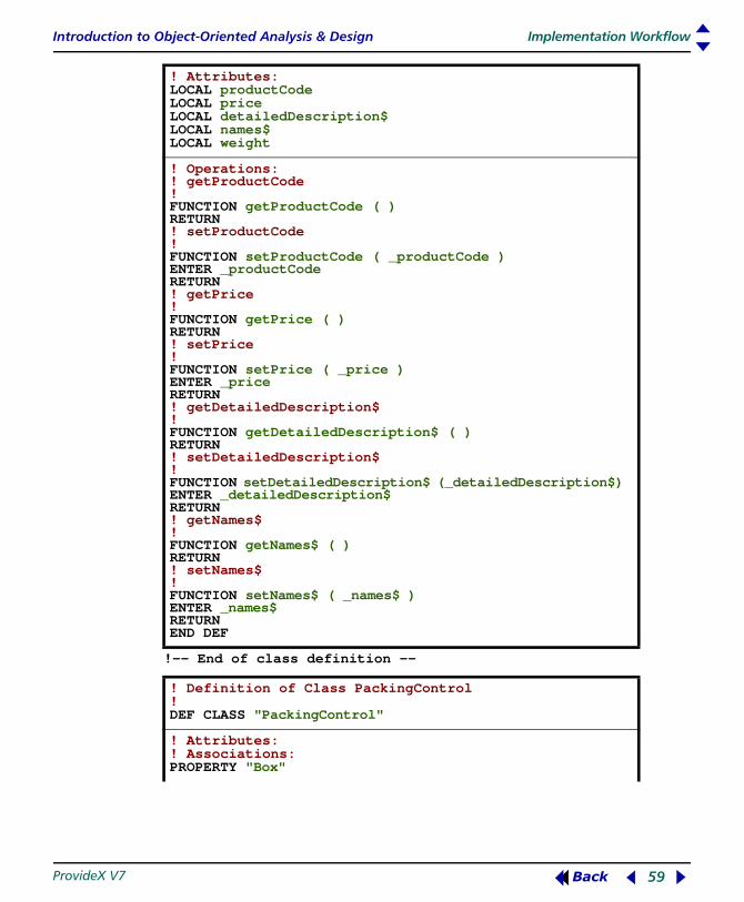
Introduction to Object-Oriented Analysis & Design Implementation Workflow
ProvideX V7 59 Back
!-- End of class definition --
! Attributes:LOCAL productCode LOCAL price LOCAL detailedDescription$ LOCAL names$ LOCAL weight
! Operations: ! getProductCode ! FUNCTION getProductCode ( ) RETURN ! setProductCode ! FUNCTION setProductCode ( _productCode ) ENTER _productCode RETURN ! getPrice ! FUNCTION getPrice ( ) RETURN ! setPrice ! FUNCTION setPrice ( _price ) ENTER _price RETURN ! getDetailedDescription$ ! FUNCTION getDetailedDescription$ ( ) RETURN ! setDetailedDescription$ ! FUNCTION setDetailedDescription$ (_detailedDescription$) ENTER _detailedDescription$ RETURN ! getNames$ ! FUNCTION getNames$ ( ) RETURN ! setNames$ ! FUNCTION setNames$ ( _names$ ) ENTER _names$ RETURN END DEF
! Definition of Class PackingControl ! DEF CLASS "PackingControl"
! Attributes:! Associations: PROPERTY "Box"
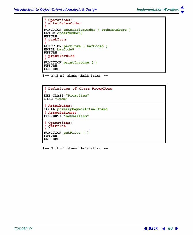
Introduction to Object-Oriented Analysis & Design Implementation Workflow
ProvideX V7 60 Back
!-- End of class definition --
!-- End of class definition --
! Operations: ! enterSalesOrder ! FUNCTION enterSalesOrder ( orderNumber$ ) ENTER orderNumber$ RETURN ! packItem ! FUNCTION packItem ( barCode$ ) ENTER barCode$ RETURN ! printInvoice ! FUNCTION printInvoice ( ) RETURN END DEF
! Definition of Class ProxyItem! DEF CLASS "ProxyItem"LIKE "Item"
! Attributes:LOCAL primaryKeyForActualItem$ ! Associations: PROPERTY "ActualItem"
! Operations: ! getPrice ! FUNCTION getPrice ( ) RETURN END DEF

Introduction to Object-Oriented Analysis & Design Implementation Workflow
ProvideX V7 61 Back
!-- End of class definition --
!-- End of class definition --
! Definition of Class Purchaser ! DEF CLASS "Purchaser"
! Attributes:LOCAL billingAddress$ LOCAL idNumber LOCAL defaultShipTo$ LOCAL customerNames$ ! Associations: LOCAL "SalesOrder"
! Operations: ! getPrice ! FUNCTION exportCustomer ( invoiceBuilder ) ENTER invoiceBuilder RETURN END DEF
! Definition of Class SalesOrder ! DEF CLASS "SalesOrder"
! Attributes:LOCAL idNumber LOCAL dateOrderWasPlaced LOCAL requireByDate LOCAL itemsOrdered ! Associations: PROPERTY Box PROPERTY Purchaser PROPERTY Group
! Operations: ! addBox ! FUNCTION addBox ( box ) ENTER box RETURN ! getPrintableInvoice ! FUNCTION getPrintableInvoice ( ) RETURN END DEF

Introduction to Object-Oriented Analysis & Design Implementation Workflow
ProvideX V7 62 Back
!-- End of class definition --
!-- End of class definition --
! Definition of Class SalesOrderList ! DEF CLASS "SalesOrderList"LIKE "HashCollection"
! Attributes:
! Operations: ! findItemByKey$ ! FUNCTION findItemByKey$ ( key$ ) ENTER key$ RETURN ! item ! FUNCTION item ( index ) ENTER index RETURN END DEF
! Definition of Class TextInvoiceBuilder ! DEF CLASS "TextInvoiceBuilder"LIKE "InvoiceBuilder"
! Attributes:
! Operations: ! addCustomer ! FUNCTION addCustomer ( name$, billingAddress$ ) ENTER name$, billingAddress$ RETURN ! addSalesOrderNumber ! FUNCTION addSalesOrderNumber ( orderNumber$ ) ENTER orderNumber$ RETURN ! addItem ! FUNCTION addItem ( itemName$, itemPrice ) ENTER itemName$, itemPrice RETURN ! buildInvoice ! FUNCTION buildInvoice ( ) RETURN END DEF

![Object-oriented Programming with PHP · Object-oriented Programming with PHP [2 ] Object-oriented programming Object-oriented programming is a popular programming paradigm where concepts](https://img.dokumen.tips/doc/110x75/5e1bb46bfe726d12f8517bf0/object-oriented-programming-with-php-object-oriented-programming-with-php-2-object-oriented.jpg)