Embed Size (px)
Citation preview

Introduction & Lab ILab Equipment & Organization
Shlomo HershkopColumbia University
Fall 2006
Announcements
Introducing the TA Archana Rao maybe one more (depending on enrollment numbers)
Lab Setup Online Poll
please take the office hours poll so we can accommodate everyone’s preferences
Lab times we need to confirm all lab groups (3/4 members) might switch around some people for spreading out experience need to confirm specific lab times

Internet Lab Equipment
4 Cisco 2600 Routers
4 Linux PCs(Intel Celeron 400MHz, 256MB Ram, 40GB disk, cdrom, floppy)
4 Ethernet hubs2x 5-port Hub 3Com OfficeConnect Dual Speed (10/100)2x 8-port Hub NETGEAR DS108
Dual monitor, keyboard, mouse
1 KVM switch can accommodate two users at once
Cables pretty colors

Internet Lab Equipment

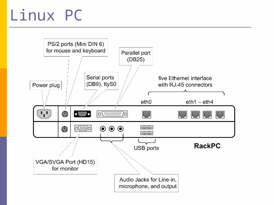
Linux PCs
PCs are labeled as: RackPC1, RackPC2, etc.
PCs run Linux (Redhat)
Each PC has: a floppy drive, a cdrom drive, 2 usb ports a serial port, 5x 10/100 Mbps Ethernet
interface cards (NICs) named eth0 – eth4.
Linux PC
Cisco Routers
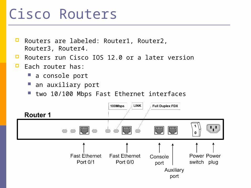
Routers are labeled: Router1, Router2, Router3, Router4. Routers run Cisco IOS 12.0 or a later version Each router has:
a console port an auxiliary port two 10/100 Mbps Fast Ethernet interfaces
Ethernet Hubs
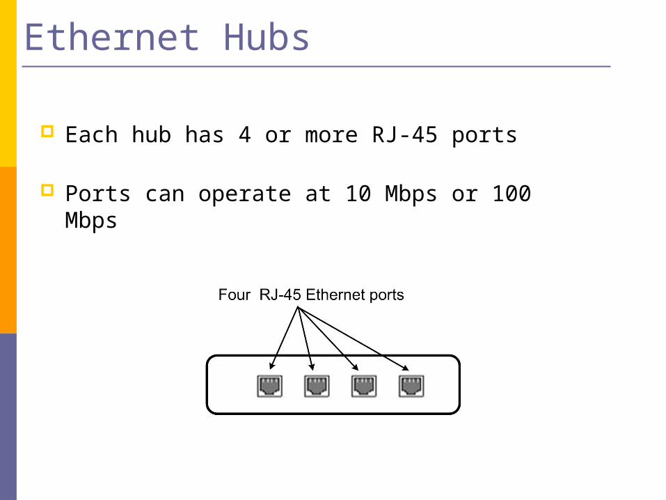
Each hub has 4 or more RJ-45 ports
Ports can operate at 10 Mbps or 100 Mbps

Lab Sequence
Core Labs:
Lab 2 - SingleSegment IPNetworks
Lab 1 -Introduction to
the Internet Lab
Lab 3 - StaticRouting
Lab 4 -DynamicRouting
Protocols
Lab 5 -TransportProtocols:
UDP and TCP
Advanced Labs:
Lab 7 - NATand DHCP
Lab 6 - LANswitching
Lab 8 - DomainName System
Lab 9 - SNMPLab 10 - IPMulticast
Core Labs
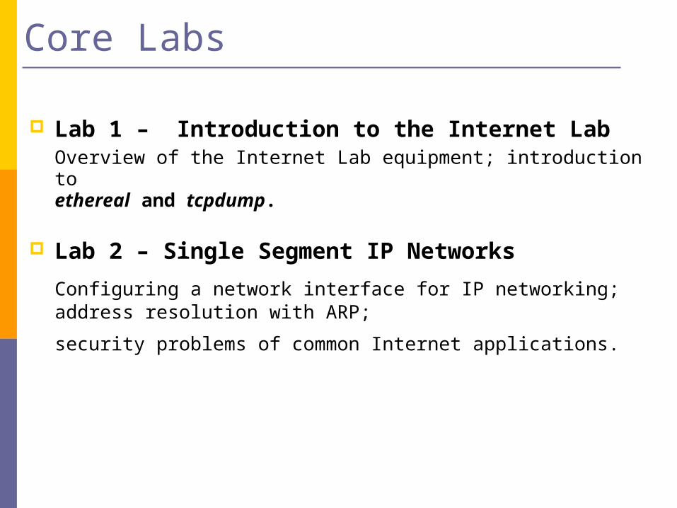
Lab 1 – Introduction to the Internet LabOverview of the Internet Lab equipment; introduction to ethereal and tcpdump.
Lab 2 – Single Segment IP Networks
Configuring a network interface for IP networking; address resolution with ARP;
security problems of common Internet applications.
Core Labs (cont.)
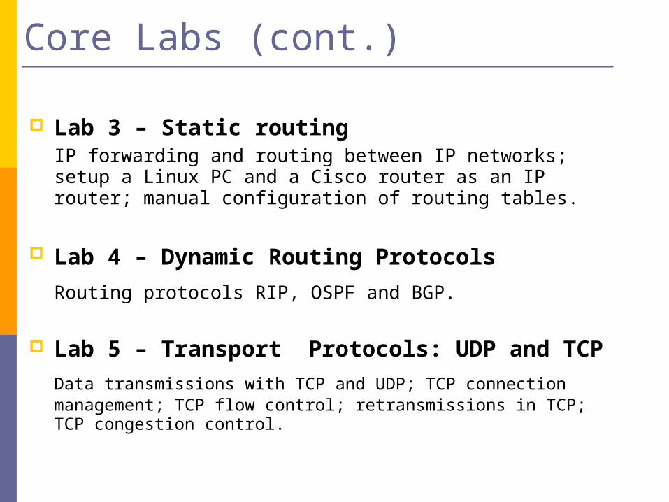
Lab 3 – Static routingIP forwarding and routing between IP networks; setup a Linux PC and a Cisco router as an IP router; manual configuration of routing tables.
Lab 4 – Dynamic Routing Protocols Routing protocols RIP, OSPF and BGP.
Lab 5 – Transport Protocols: UDP and TCP
Data transmissions with TCP and UDP; TCP connection management; TCP flow control; retransmissions in TCP; TCP congestion control.
Advanced Labs
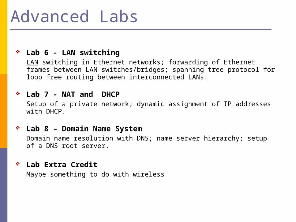
Lab 6 - LAN switchingLAN switching in Ethernet networks; forwarding of Ethernet frames between LAN switches/bridges; spanning tree protocol for loop free routing between interconnected LANs.
Lab 7 - NAT and DHCP Setup of a private network; dynamic assignment of IP addresses with DHCP.
Lab 8 – Domain Name SystemDomain name resolution with DNS; name server hierarchy; setup of a DNS root server.
Lab Extra CreditMaybe something to do with wireless

Structure of the Labs
Each lab has three phases: Pre-laboratory Assignment (Prelab) Lab Session Lab Reports
Structure of the Labs (cont.)
Pre-laboratory Assignment (Pre-lab)
Exercises to be completed in advance of the associated lab session.
The pre-labs ask you to acquire background knowledge that is needed during the lab exercises.
Each pre-lab has a question sheet that must be completed before the corresponding lab session.
The answers to the prelab questions are graded.

Structure of the Labs (cont.)
Lab Session. Lab exercises that are performed on the equipment of the
Internet lab. All lab exercises can be completed without supervision. The time to complete a lab session should be three hours on the average, but may vary. Complete the laboratory activities to the extent that you can. The activities during the lab session are not graded, however, data collected during the lab session are needed to complete a lab report.
Floppy disk symbol in the lab manual indicates when you have to collect data.
Floppy disk symbol
Structure of the Labs (cont.)
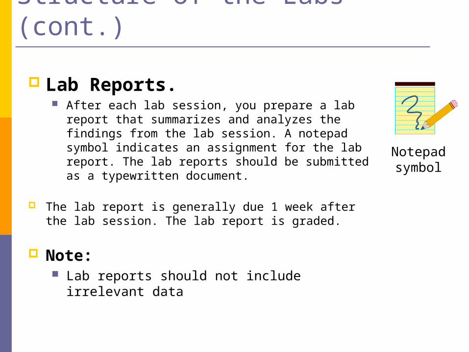
Lab Reports. After each lab session, you prepare a lab report that
summarizes and analyzes the findings from the lab session. A notepad symbol indicates an assignment for the lab report. The lab reports should be submitted as a typewritten document.
The lab report is generally due 1 week after the lab session. The lab report is graded.
Note: Lab reports should not include irrelevant data
Notepad symbol
In the Lab:
1. I am trying to get USB keys, in the meantime, either have one of the group members dig one up (no questions asked, or use provided floppies (please don’t offload them on ebay)
2. Reboot Linux PCs
3. Complete exercises as described in the lab manual
4. Take measurements as instructed
5. Save data to floppy disk

Additional notes
The equipment of the Internet Lab is not connected to the Internet. you can bring in a laptop (best) and connect wired or wirelessly
Each lab has an anonymous feedback sheet. The feedback is used to improve the setup and organization of the labs.
Since you have administrative (root) privileges on the Internet Lab equipment, exercise caution when modifying the configuration of the Internet Lab equipment.
Introductory material.
This module illustrates the interactions of the protocols of the TCP/IP protocol suite with the help of an example. The example intents to motivate the study of the TCP/IP protocols.
TCP/IP NetworkingAn Example
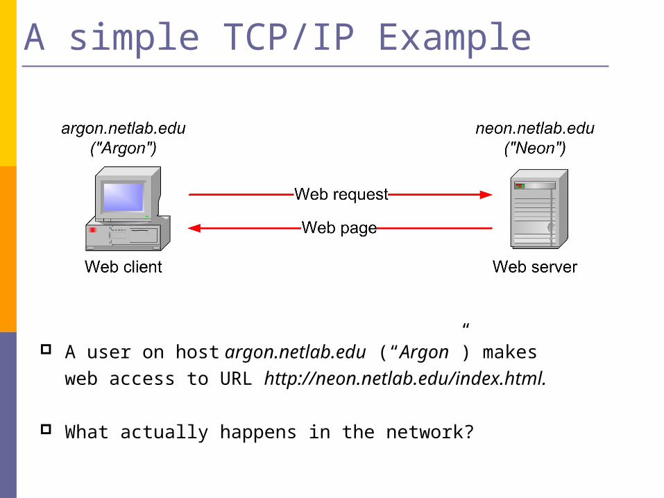
A user on host argon.netlab.edu (“Argon”) makes web access
to URL http://neon.netlab.edu/index.html.
What actually happens in the network?
A simple TCP/IP Example
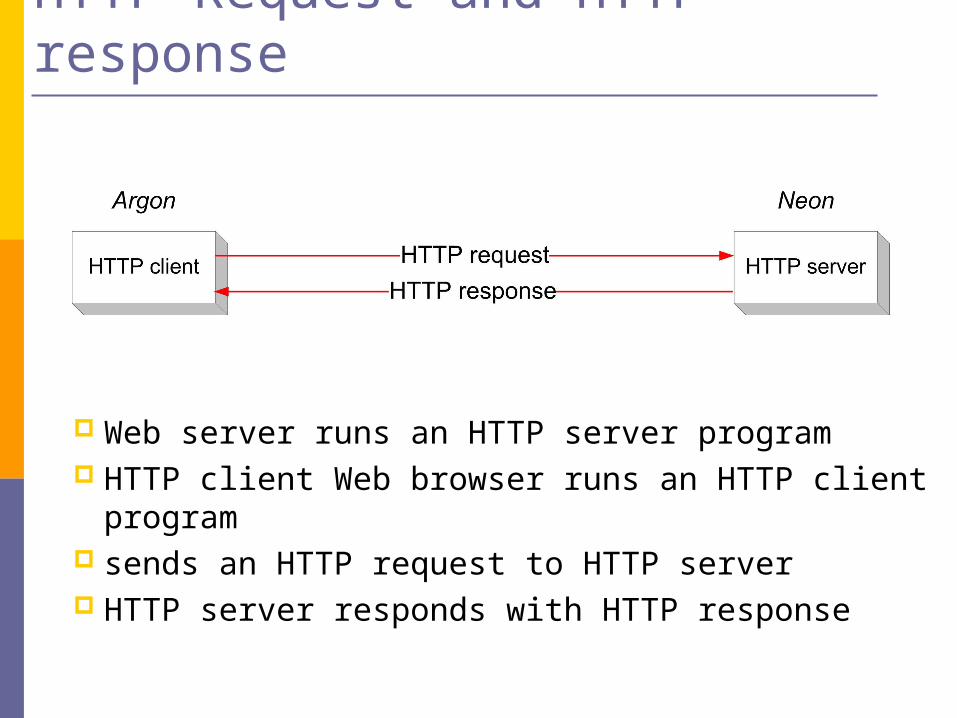
HTTP Request and HTTP response
Web server runs an HTTP server program HTTP client Web browser runs an HTTP client program sends an HTTP request to HTTP server HTTP server responds with HTTP response

HTTP Request
GET /example.html HTTP/1.1
Accept: image/gif, */*
Accept-Language: en-us
Accept-Encoding: gzip, deflate
User-Agent: Mozilla/4.0
Host: 192.168.123.144
Connection: Keep-Alive

HTTP Response
HTTP/1.1 200 OK
Date: Sat, 25 May 2002 21:10:32 GMT
Server: Apache/1.3.19 (Unix)
Last-Modified: Sat, 25 May 2002 20:51:33 GMT
ETag: "56497-51-3ceff955"
Accept-Ranges: bytes
Content-Length: 81
Keep-Alive: timeout=15, max=100
Connection: Keep-Alive
Content-Type: text/html
<HTML>
<BODY>
<H1>Internet Lab</H1>
Click <a href="http://www.netlab.net/index.html">here</a> for the Internet Lab webpage.
</BODY>
</HTML>
• How does the HTTP request get from Argon to Neon ?
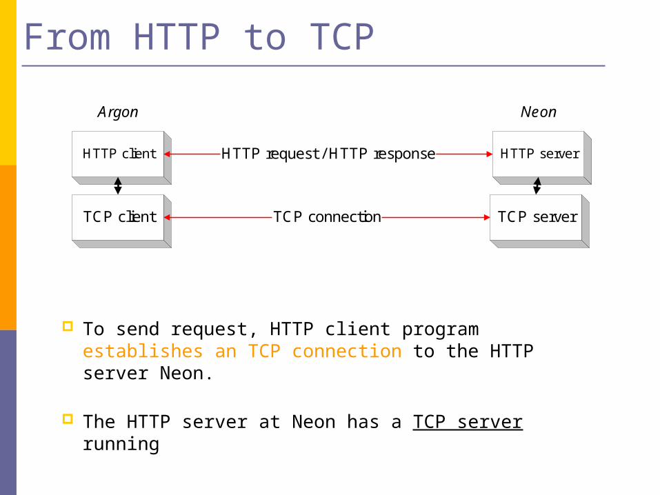
From HTTP to TCP
To send request, HTTP client program establishes an TCP connection to the HTTP server Neon.
The HTTP server at Neon has a TCP server running
HTTP client
TCP client
Argon
HTTP server
TCP server
Neon
HTTP request / HTTP response
TCP connection

Resolving hostnames and port numbers
Since TCP does not work with hostnames and also would not know how to find the HTTP server program at Neon, two things must happen:
1. The name “neon.netlab.edu” must be translated into a
32-bit IP address.
2. The HTTP server at Neon must be identified by a 16-bit port number.

Translating a hostname into an IP address
The translation of the hostname neon.netlab.edu into an IP address is done via a database lookup
The distributed database used is called the Domain Name System (DNS)
All machines on the Internet have an IP address:argon.netlab.edu 128.143.137.144neon.netlab.edu 128.143.71.21
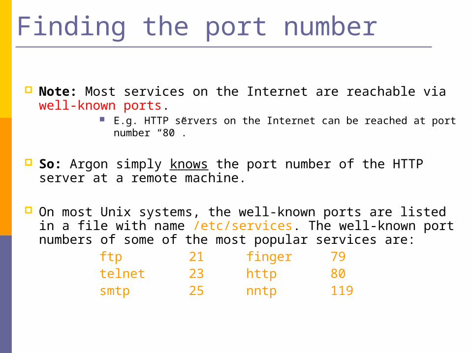
Finding the port number
Note: Most services on the Internet are reachable via well-known ports. E.g. HTTP servers on the Internet can be reached at port number “80”.
So: Argon simply knows the port number of the HTTP server at a remote machine.
On most Unix systems, the well-known ports are listed in a file with name /etc/services. The well-known port numbers of some of the most popular services are:
ftp21 finger 79telnet 23 http 80smtp 25 nntp 119
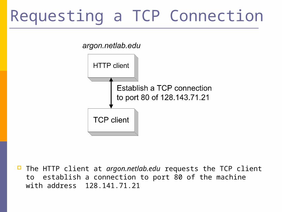
Requesting a TCP Connection
The HTTP client at argon.netlab.edu requests the TCP client to establish a connection to port 80 of the machine with address 128.141.71.21
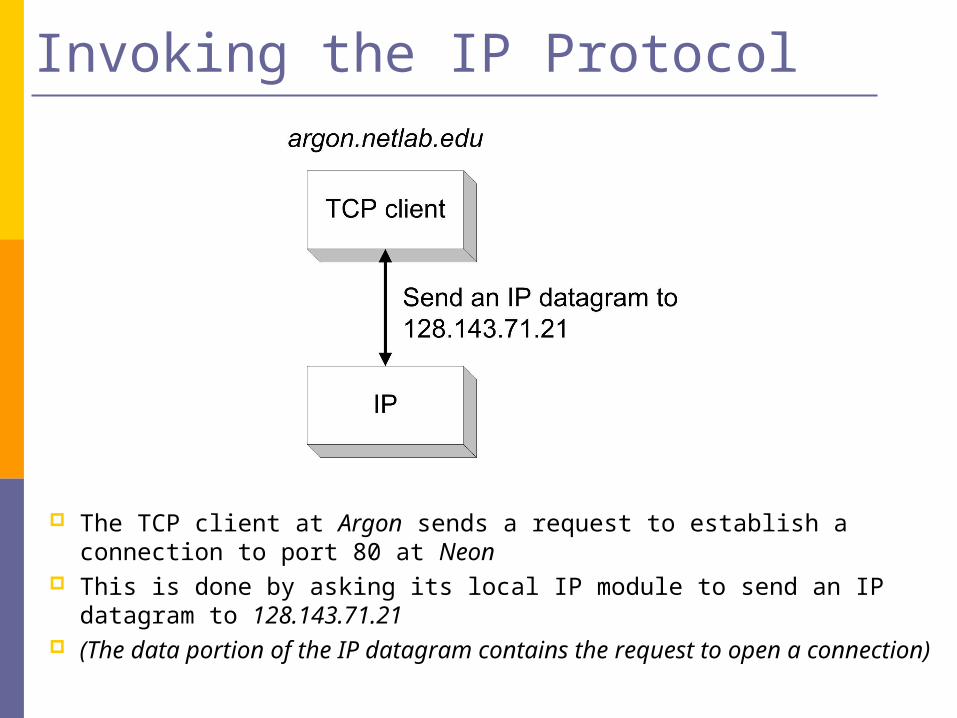
Invoking the IP Protocol
The TCP client at Argon sends a request to establish a connection to port 80 at Neon
This is done by asking its local IP module to send an IP datagram to 128.143.71.21
(The data portion of the IP datagram contains the request to open a connection)
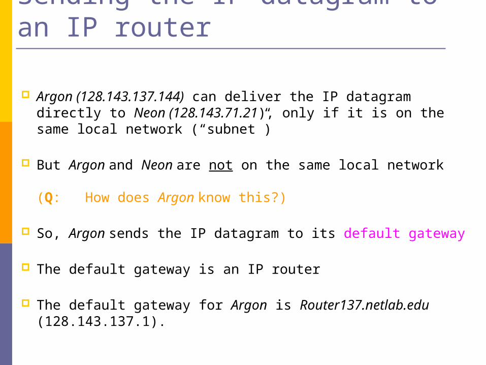
Sending the IP datagram to an IP router
Argon (128.143.137.144) can deliver the IP datagram directly to Neon (128.143.71.21), only if it is on the same local network (“subnet”)
But Argon and Neon are not on the same local network (Q: How does Argon know this?)
So, Argon sends the IP datagram to its default gateway
The default gateway is an IP router
The default gateway for Argon is Router137.netlab.edu (128.143.137.1).
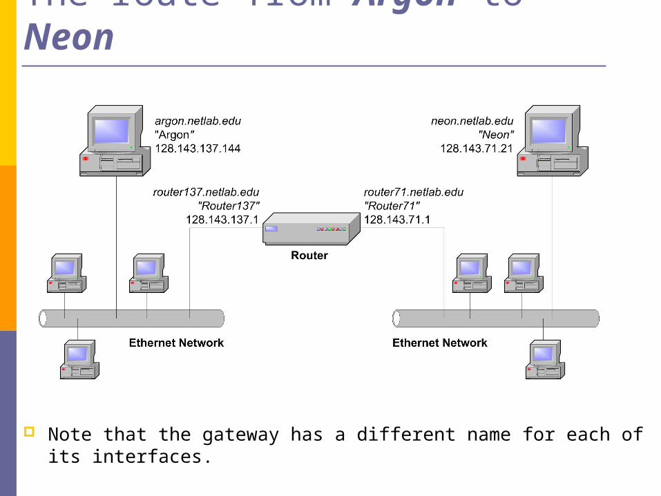
The route from Argon to Neon
Note that the gateway has a different name for each of its interfaces.

Finding the MAC address of the gateway
To send an IP datagram to Router137, Argon puts the IP datagram in an Ethernet frame, and transmits the frame.
However, Ethernet uses different addresses, so-called Media Access Control (MAC) addresses (also called: physical address, hardware address).
Therefore, Argon must first translate the IP address 128.143.137.1 into a MAC address.
The translation of addressed is performed via the Address Resolution Protocol (ARP)
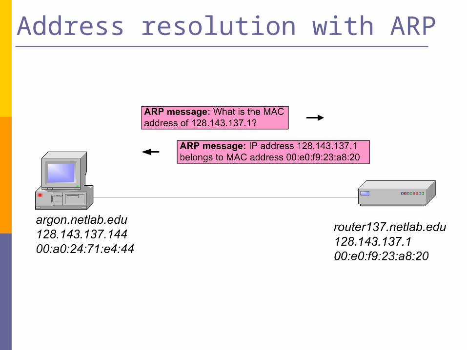
Address resolution with ARP
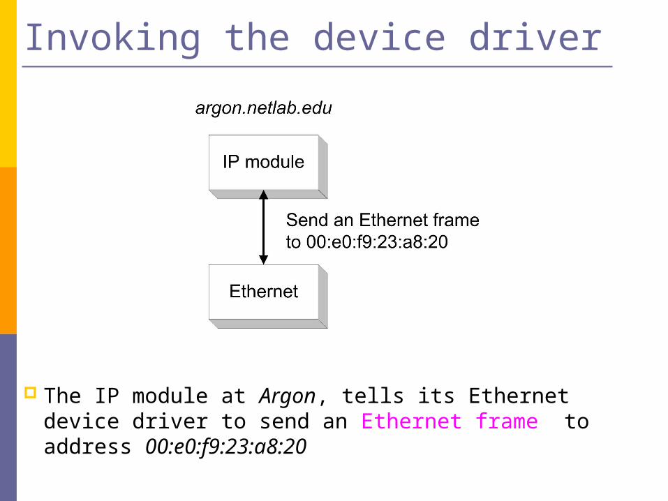
Invoking the device driver
The IP module at Argon, tells its Ethernet device driver to send an Ethernet frame to address 00:e0:f9:23:a8:20

Sending an Ethernet frame
The Ethernet device driver of Argon sends the Ethernet frame to the Ethernet network interface card (NIC)
The NIC sends the frame onto the wire
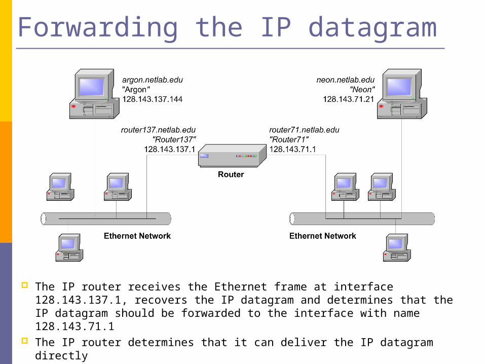
Forwarding the IP datagram
The IP router receives the Ethernet frame at interface 128.143.137.1, recovers the IP datagram and determines that the IP datagram should be forwarded to the interface with name 128.143.71.1
The IP router determines that it can deliver the IP datagram directly
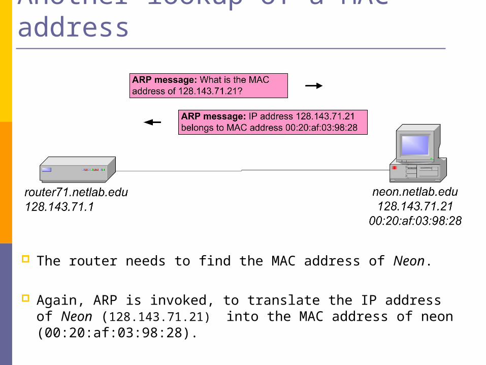
Another lookup of a MAC address
The router needs to find the MAC address of Neon.
Again, ARP is invoked, to translate the IP address of Neon (128.143.71.21) into the MAC address of neon (00:20:af:03:98:28).
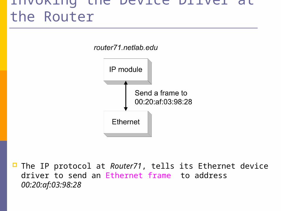
The IP protocol at Router71, tells its Ethernet device driver to send an Ethernet frame to address 00:20:af:03:98:28
Invoking the Device Driver at the Router
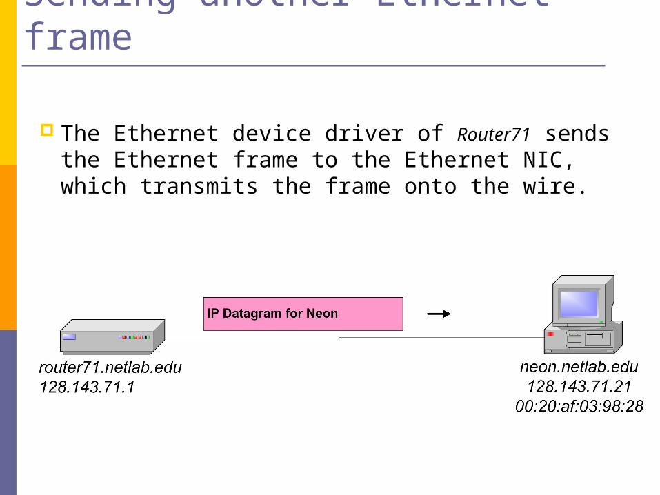
Sending another Ethernet frame
The Ethernet device driver of Router71 sends the Ethernet frame to the Ethernet NIC, which transmits the frame onto the wire.
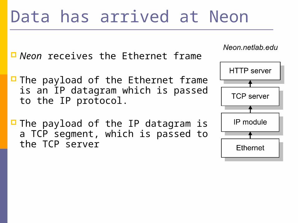
Data has arrived at Neon
Neon receives the Ethernet frame
The payload of the Ethernet frame is an IP datagram which is passed to the IP protocol.
The payload of the IP datagram is a TCP segment, which is passed to the TCP server
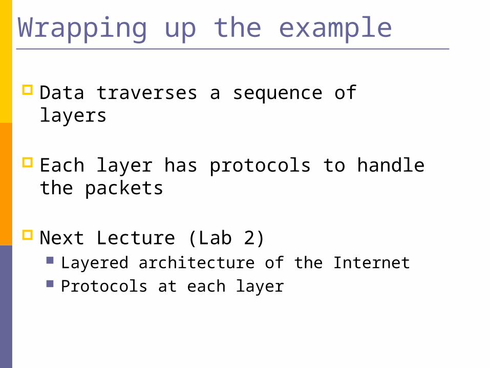
Wrapping up the example
Data traverses a sequence of layers
Each layer has protocols to handle the packets
Next Lecture (Lab 2) Layered architecture of the Internet Protocols at each layer
Review of Important Networking Concepts
Introductory material using Prof. Liebeherr on-line notes
Review of important networking concepts: protocol architecture, protocol layers, encapsulation, demultiplexing, network abstractions.
Networking Concepts
Layered Architecture to reduce complexity Encapsulation Abstractions
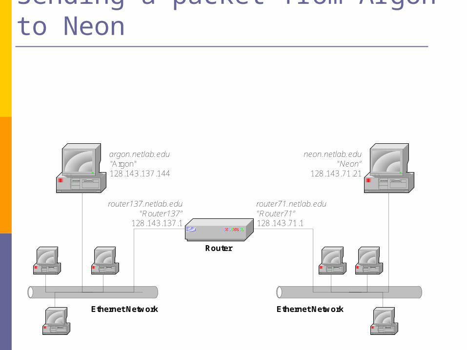
neon.netlab.edu"Neon"
128.143.71.21
argon.netlab.edu "Argon"128.143.137.144
router137.netlab.edu"Router137"
128.143.137.1
router71.netlab.edu"Router71"128.143.71.1
Ethernet NetworkEthernet Network
Router
Sending a packet from Argon to Neon
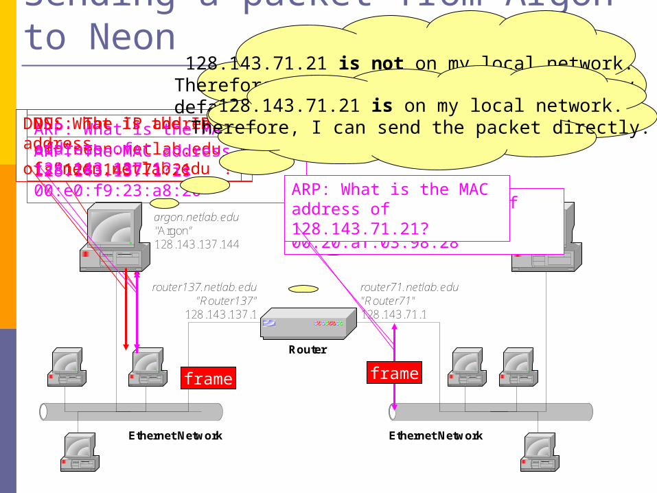
DNS: The IP address of
“neon.netlab.edu” is 128.143.71.21
ARP: What is the MAC address of 128.143.137.1?
neon.netlab.edu"Neon"
128.143.71.21
argon.netlab.edu "Argon"128.143.137.144
router137.netlab.edu"Router137"
128.143.137.1
router71.netlab.edu"Router71"128.143.71.1
Ethernet NetworkEthernet Network
Router
Sending a packet from Argon to Neon
DNS: What is the IP address
of “neon.netlab.edu”?ARP: The MAC address of 128.143.137.1 is 00:e0:f9:23:a8:20
128.143.71.21 is not on my local network.Therefore, I need to send the packet to my
default gateway with address 128.143.137.1
frame
128.143.71.21 is on my local network.Therefore, I can send the packet directly.
ARP: The MAC address of 128.143.137.1 is 00:20:af:03:98:28
ARP: What is the MAC address of 128.143.71.21?
frame
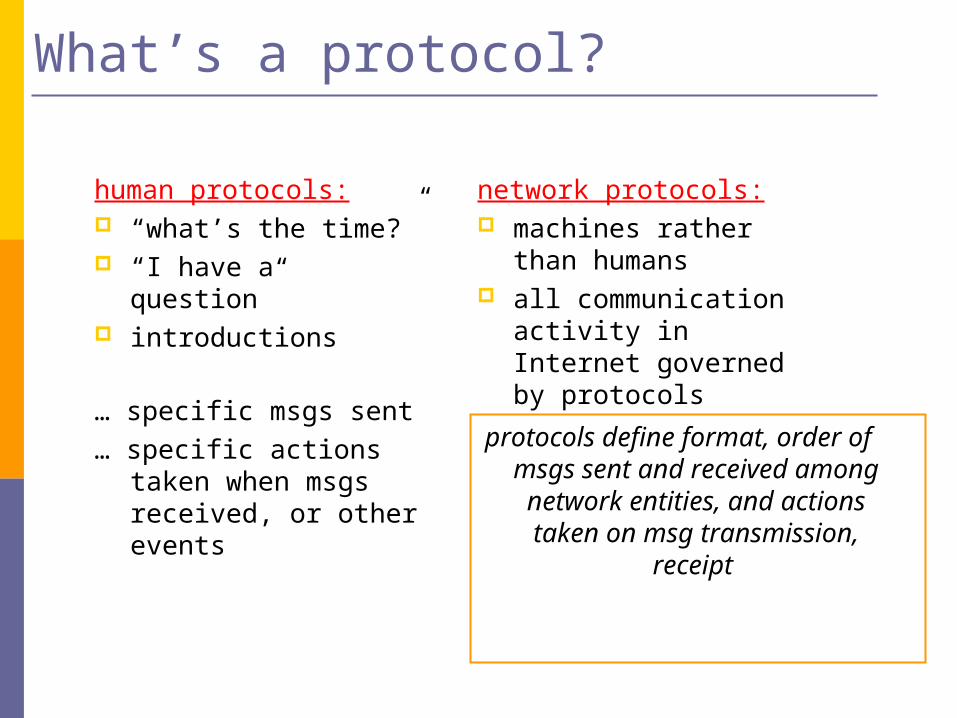
What’s a protocol?
human protocols: “what’s the time?” “I have a question” introductions
… specific msgs sent
… specific actions taken when msgs received, or other events
network protocols: machines rather than
humans all communication activity
in Internet governed by protocols
protocols define format, order of msgs sent and received among
network entities, and actions taken on msg transmission,
receipt

What’s a protocol?
a human protocol and a computer network protocol:
Q: Other human protocols?
Hi
Hi
Got thetime?
2:00
TCP connection req
TCP connectionresponseGet http://www.awl.com/kurose-ross
<file>time
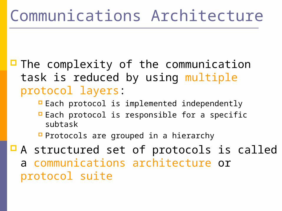
Communications Architecture
The complexity of the communication task is reduced by using multiple protocol layers:
Each protocol is implemented independently Each protocol is responsible for a specific subtask Protocols are grouped in a hierarchy
A structured set of protocols is called a communications architecture or protocol suite
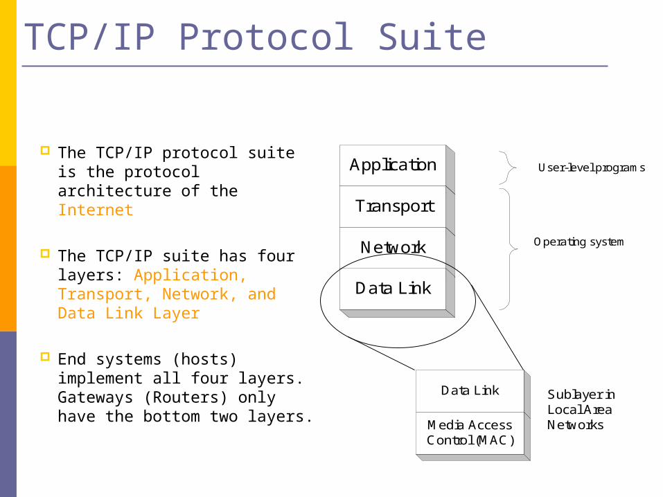
TCP/IP Protocol Suite
The TCP/IP protocol suite is the protocol architecture of the Internet
The TCP/IP suite has four layers: Application, Transport, Network, and Data Link Layer
End systems (hosts) implement all four layers. Gateways (Routers) only have the bottom two layers.
Application
Transport
Network Operating system
User-level programs
Data Link
Data Link
Media AccessControl (MAC)
Sublayer inLocal AreaNetworks
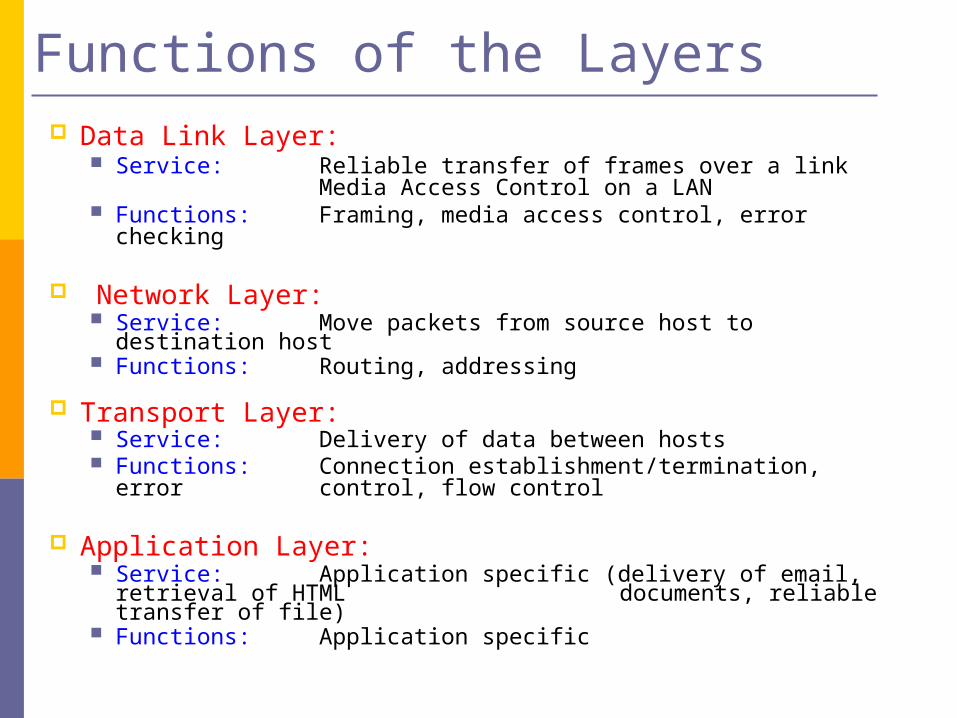
Functions of the Layers Data Link Layer:
Service: Reliable transfer of frames over a linkMedia Access Control on a LAN
Functions: Framing, media access control, error checking
Network Layer: Service: Move packets from source host to destination
host Functions: Routing, addressing
Transport Layer: Service: Delivery of data between hosts Functions: Connection establishment/termination, error
control, flow control
Application Layer: Service: Application specific (delivery of email, retrieval of
HTML documents, reliable transfer of file) Functions: Application specific
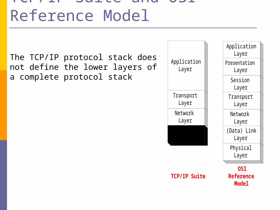
TCP/IP Suite and OSI Reference Model
ApplicationLayer
ApplicationLayer
PresentationLayer
SessionLayer
TransportLayer
NetworkLayer
(Data) LinkLayer
PhysicalLayer
TransportLayer
NetworkLayer
OSIReference
Model
(Data) LinkLayer
TCP/IP Suite
The TCP/IP protocol stack does not define the lower layers of a complete protocol stack
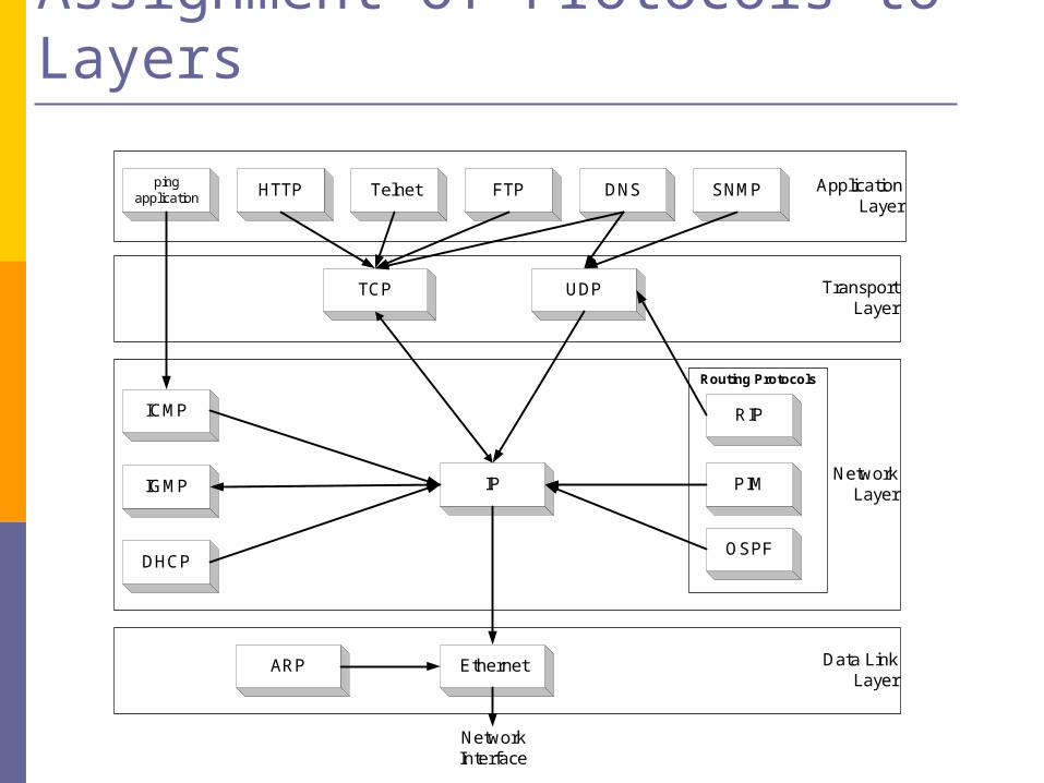
Assignment of Protocols to Layers
NetworkLayer
Routing Protocols
PIM
OSPF
RIP
ApplicationLayer
Data LinkLayer
IP
ARP Ethernet
NetworkInterface
TransportLayer
TCP UDP
SNMPFTP DNSHTTP
ICMP
IGMP
pingapplication Telnet
DHCP

Layered Communications
An entity of a particular layer can only communicate with:1. a peer layer entity using a common protocol (Peer
Protocol)
2. adjacent layers to provide services and to receive services
N+1 LayerEntity
N+1 LayerEntity
N+1 Layer ProtocolN+1 Layer
N-1 LayerEntity
N-1 LayerEntity
N-1 Layer ProtocolN-1 Layer
N LayerEntity
N LayerEntity
N Layer ProtocolN Layer
layer N+1/Ninterface
layer N/N-1interface

Service Primitives
N+1 LayerEntity
N+1 LayerEntity
N LayerEntity
N LayerEntity
N+1 Layer Peer Protocol
Request Delivery
IndicateDelivery
Communication services are invoked via function calls. The functions are called service primitives
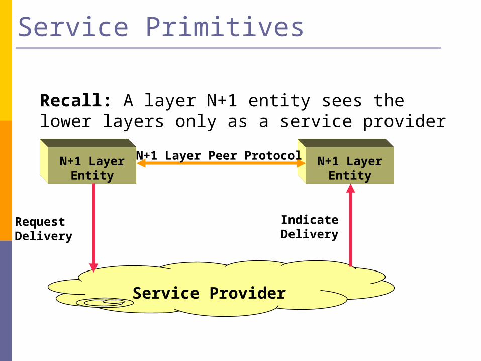
Service Primitives
Recall: A layer N+1 entity sees the lower layers only as a service provider
Service Provider
N+1 LayerEntity
N+1 LayerEntity
N+1 Layer Peer Protocol
Request Delivery
IndicateDelivery
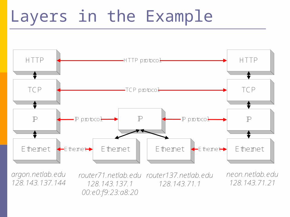
Layers in the Example
HTTP
TCP
IP
argon.netlab.edu128.143.137.144
Ethernet Ethernet Ethernet
IP
HTTP
TCP
IP
neon.netlab.edu128.143.71.21
Ethernet
router71.netlab.edu128.143.137.1
00:e0:f9:23:a8:20
router137.netlab.edu128.143.71.1
HTTP protocol
TCP protocol
IP protocol
Ethernet
IP protocol
Ethernet
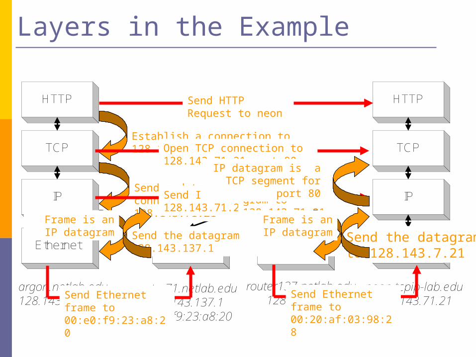
Layers in the Example
HTTP
TCP
IP
argon.netlab.edu128.143.137.144
Ethernet Ethernet Ethernet
IP
HTTP
TCP
IP
neon.tcpip-lab.edu128.143.71.21
Ethernet
router71.netlab.edu128.143.137.1
00:e0:f9:23:a8:20
router137.netlab.edu128.143.71.1
Send HTTP Request to neon
Establish a connection to 128.143.71.21 at port 80Open TCP connection to
128.143.71.21 port 80
Send a datagram (which contains a connection request) to 128.143.71.21Send IP datagram to
128.143.71.21
Send the datagram to 128.143.137.1
Send Ethernet frame to 00:e0:f9:23:a8:20
Send Ethernet frame to 00:20:af:03:98:28
Send IP data-gram to 128.143.71.21
Send the datagram to 128.143.7.21
Frame is an IP datagram
Frame is an IP datagram
IP datagram is a TCP segment for port 80
Layers and Services
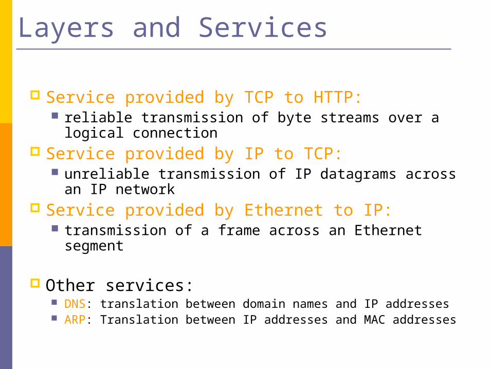
Service provided by TCP to HTTP: reliable transmission of byte streams over a logical
connection Service provided by IP to TCP:
unreliable transmission of IP datagrams across an IP network
Service provided by Ethernet to IP: transmission of a frame across an Ethernet segment
Other services: DNS: translation between domain names and IP addresses ARP: Translation between IP addresses and MAC addresses
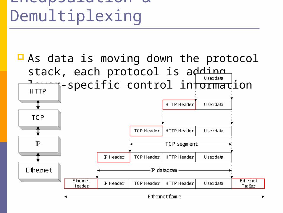
Encapsulation & Demultiplexing
As data is moving down the protocol stack, each protocol is adding layer-specific control informationHTTP
TCP
IP
Ethernet
User data
User dataHTTP Header
TCP Header
TCP HeaderIP Header
TCP HeaderIP HeaderEthernetHeader
EthernetTrailer
IP datagram
TCP segment
Ethernet frame
User dataHTTP Header
User dataHTTP Header
User dataHTTP Header
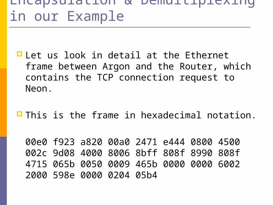
Encapsulation & Demultiplexing in our Example
Let us look in detail at the Ethernet frame between Argon and the Router, which contains the TCP connection request to Neon.
This is the frame in hexadecimal notation.
00e0 f923 a820 00a0 2471 e444 0800 4500 002c 9d08 4000 8006 8bff 808f 8990 808f 4715 065b 0050 0009 465b 0000 0000 6002 2000 598e 0000 0204 05b4
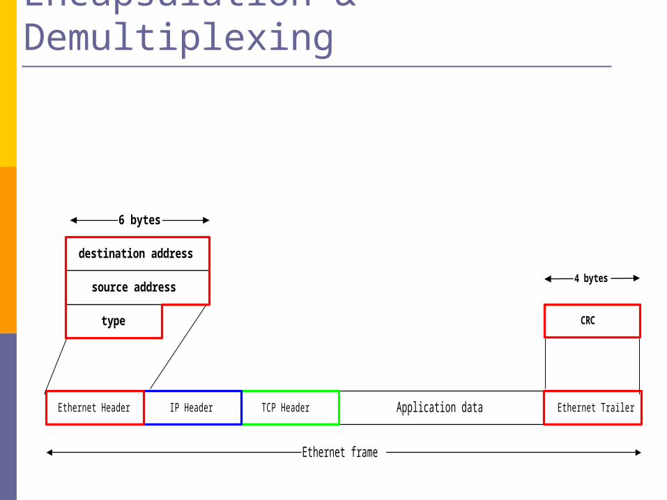
Encapsulation & Demultiplexing
Application dataTCP HeaderIP HeaderEthernet Header Ethernet Trailer
Ethernet frame
destination address
source address
type
6 bytes
CRC
4 bytes
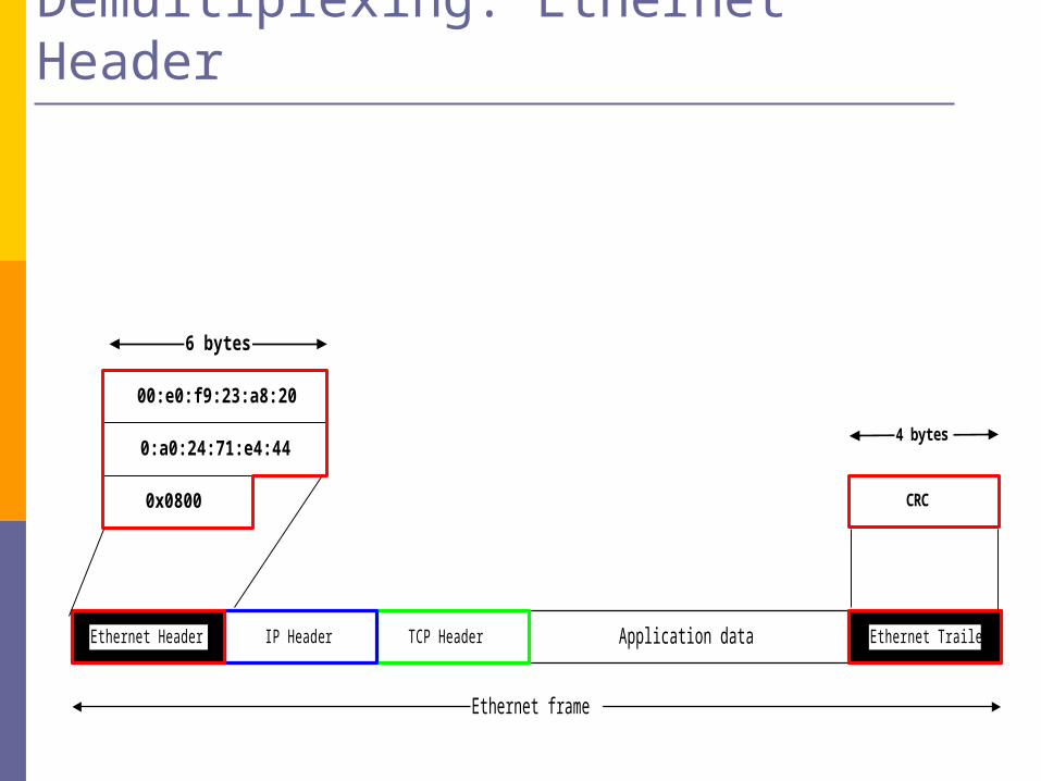
00:e0:f9:23:a8:20
0:a0:24:71:e4:44
0x0800
6 bytes
CRC
4 bytes
Encapsulation & Demultiplexing: Ethernet Header
Application dataTCP HeaderIP HeaderEthernet Header Ethernet Trailer
Ethernet frame
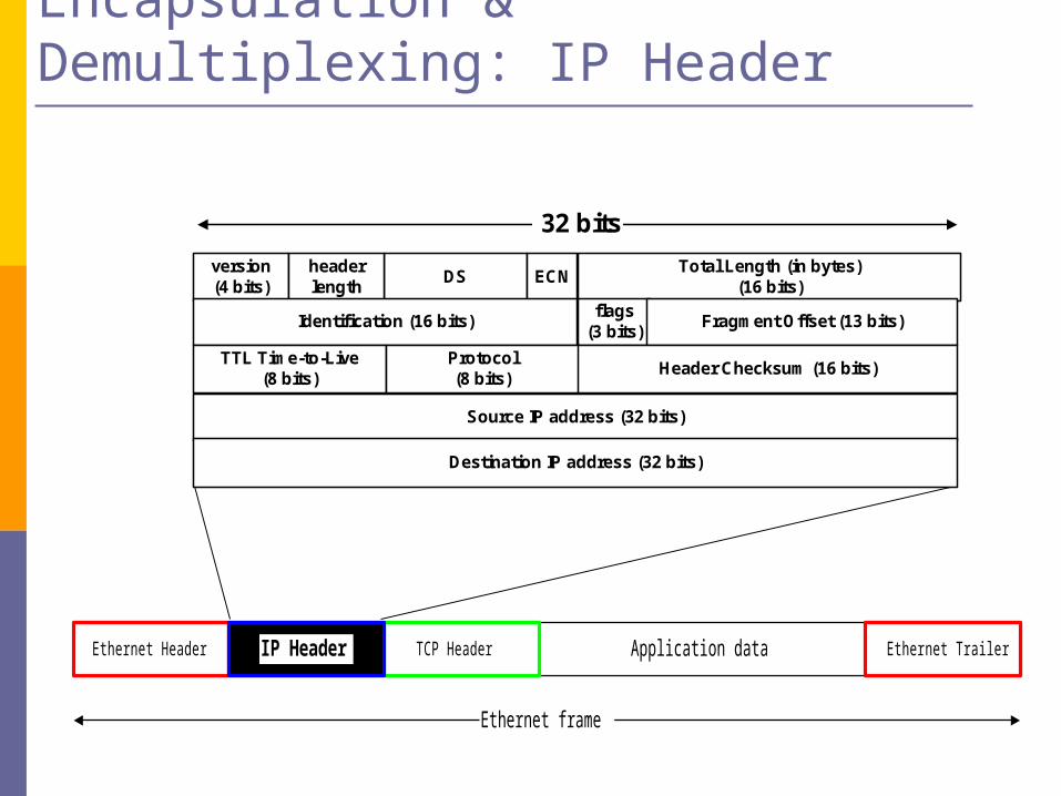
Encapsulation & Demultiplexing: IP Header
Application dataTCP HeaderEthernet Header Ethernet Trailer
Ethernet frame
IP Header
DS ECNversion(4 bits)
headerlength
Total Length (in bytes)(16 bits)
Identification (16 bits)flags
(3 bits)Fragment Offset (13 bits)
Source IP address (32 bits)
Destination IP address (32 bits)
TTL Time-to-Live(8 bits)
Protocol(8 bits)
Header Checksum (16 bits)
32 bits
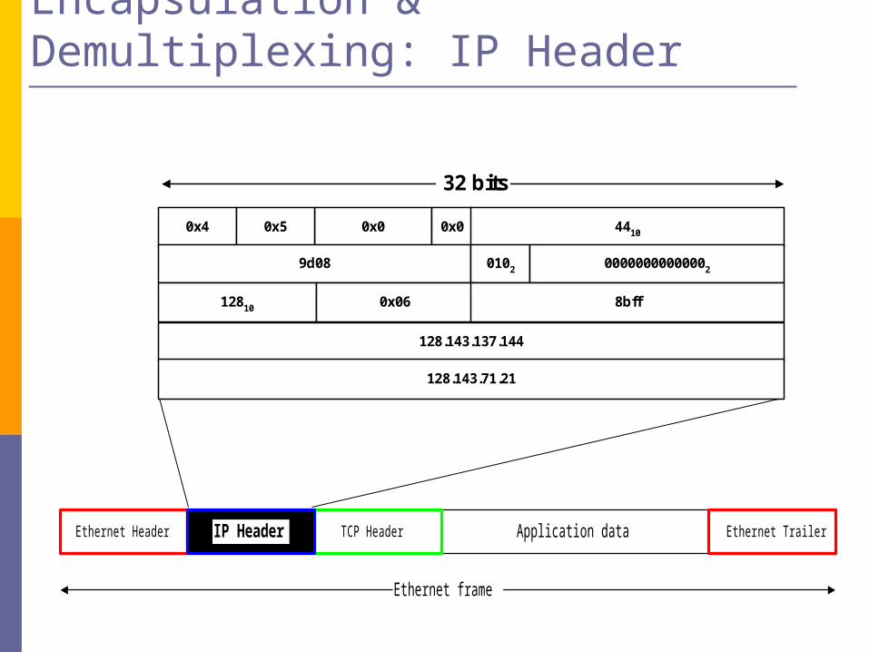
Encapsulation & Demultiplexing: IP Header
Application dataTCP HeaderEthernet Header Ethernet Trailer
Ethernet frame
IP Header
0x0 0x00x4 0x5 4410
9d08 0102 00000000000002
128.143.137.144
128.143.71.21
12810 0x06 8bff
32 bits
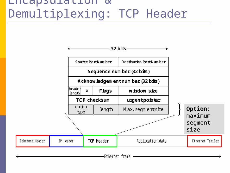
Encapsulation & Demultiplexing: TCP Header
Application dataEthernet Header Ethernet Trailer
Ethernet frame
IP Header TCP Header
Sequence number (32 bits)
Source Port Number Destination Port Number
Acknowledgement number (32 bits)
window sizeheaderlength
0 Flags
TCP checksum urgent pointer
32 bits
length Max. segment sizeoptiontype
Option: maximum segment size
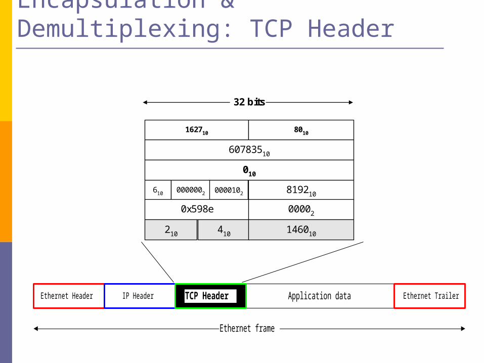
Encapsulation & Demultiplexing: TCP Header
Application dataEthernet Header Ethernet Trailer
Ethernet frame
IP Header TCP Header
60783510
162710 8010
010
819210610 0000002 0000102
0x598e 00002
32 bits
410 146010210
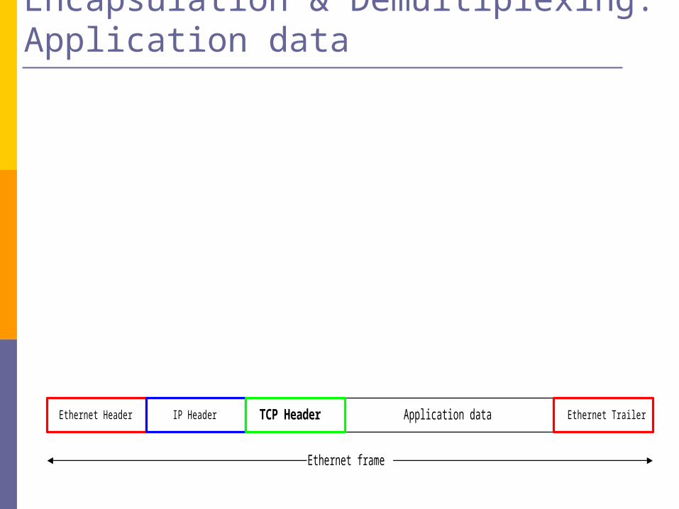
Encapsulation & Demultiplexing: Application data
Application dataEthernet Header Ethernet Trailer
Ethernet frame
IP Header TCP Header

Different Views of Networking
Different Layers of the protocol stack have a different view of the network. This is HTTP’s and TCP’s view of the network.
HTTP client
TCP client
Argon128.143.137.144
HTTPserver
TCP server
Neon128.143.71.21
IP Network
HTTPserver
TCP server
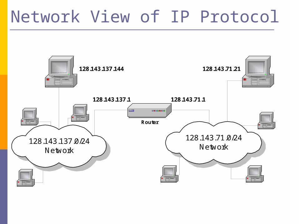
Network View of IP Protocol
128.143.71.21128.143.137.144
Router
128.143.137.0/24Network
128.143.137.1 128.143.71.1
128.143.71.0/24Network
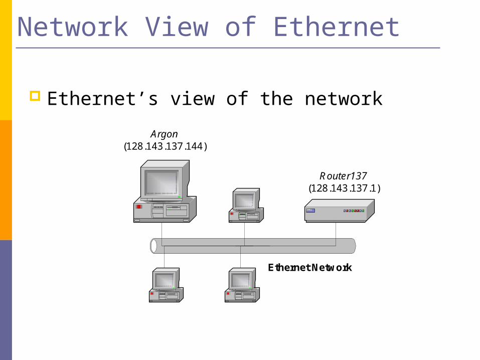
Network View of Ethernet
Ethernet’s view of the network
Argon(128.143.137.144)
Router137(128.143.137.1)
Ethernet Network
The Evolution of Internet
Introductory material.
An overview lecture that covers Internet related topics, including a definition of the Internet, an overview of its history and growth, and standardization and naming.
A Definition
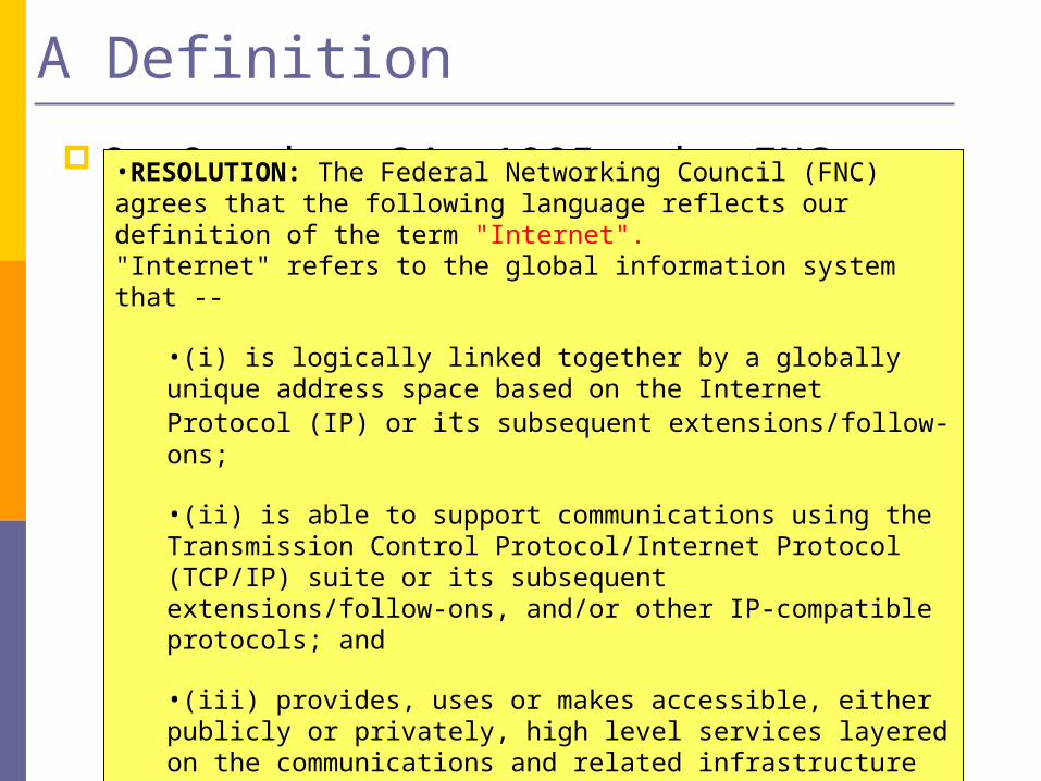
On October 24, 1995, the FNC unanimously passed a resolution defining the term Internet. •RESOLUTION: The Federal Networking Council (FNC) agrees that the following language reflects our definition of the term "Internet". "Internet" refers to the global information system that --
•(i) is logically linked together by a globally unique address space based on the Internet Protocol (IP) or its subsequent extensions/follow-ons;
•(ii) is able to support communications using the Transmission Control Protocol/Internet Protocol (TCP/IP) suite or its subsequent extensions/follow-ons, and/or other IP-compatible protocols; and
•(iii) provides, uses or makes accessible, either publicly or privately, high level services layered on the communications and related infrastructure described herein.

Internet History
1961: Kleinrock - queueing theory shows effectiveness of packet-switching
1964: Baran - packet-switching in military nets
1967: ARPAnet conceived by Advanced Research Projects Agency
1969: first ARPAnet node operational
1972: ARPAnet demonstrated
publicly NCP (Network Control
Protocol) first host-host protocol
first e-mail program ARPAnet has 15 nodes
1961-1972: Early packet-switching principles
Internet History
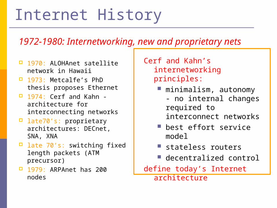
1970: ALOHAnet satellite network in Hawaii
1973: Metcalfe’s PhD thesis proposes Ethernet
1974: Cerf and Kahn - architecture for interconnecting networks
late70’s: proprietary architectures: DECnet, SNA, XNA
late 70’s: switching fixed length packets (ATM precursor)
1979: ARPAnet has 200 nodes
Cerf and Kahn’s internetworking principles: minimalism, autonomy - no
internal changes required to interconnect networks
best effort service model stateless routers decentralized control
define today’s Internet architecture
1972-1980: Internetworking, new and proprietary nets

Internet History
Early 1990’s: ARPAnet decommissioned
1991: NSF lifts restrictions on commercial use of NSFnet (decommissioned, 1995)
early 1990s: Web hypertext [Bush 1945, Nelson
1960’s] HTML, HTTP: Berners-Lee 1994: Mosaic, later Netscape late 1990’s:
commercialization of the Web
Late 1990’s – 2000’s: more killer apps:
instant messaging, P2P file sharing
network security to forefront
est. 50 million host, 100 million+ users
backbone links running at Gbps
1990, 2000’s: commercialization, the Web, new apps

Applications of the Internet
Traditional core applications:EmailNewsRemote LoginFile Transfer
The killer application:World-Wide Web (WWW), P2P
Future applications:Videoconferencing and TelephonyMultimedia ServicesInternet Broadcast

Growth of the Internet
Source: Internet Software Consortium
Internet Infrastructure
local ISP
campusnetwork
corporatenetwork
IXP
RegionalNetwork
RegionalNetwork
local ISP
local ISP
IXP
IXP
Backbone Network
Backbone Network
RegionalNetwork
RegionalNetwork
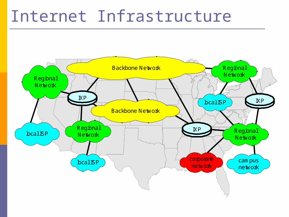
Internet Infrastructure
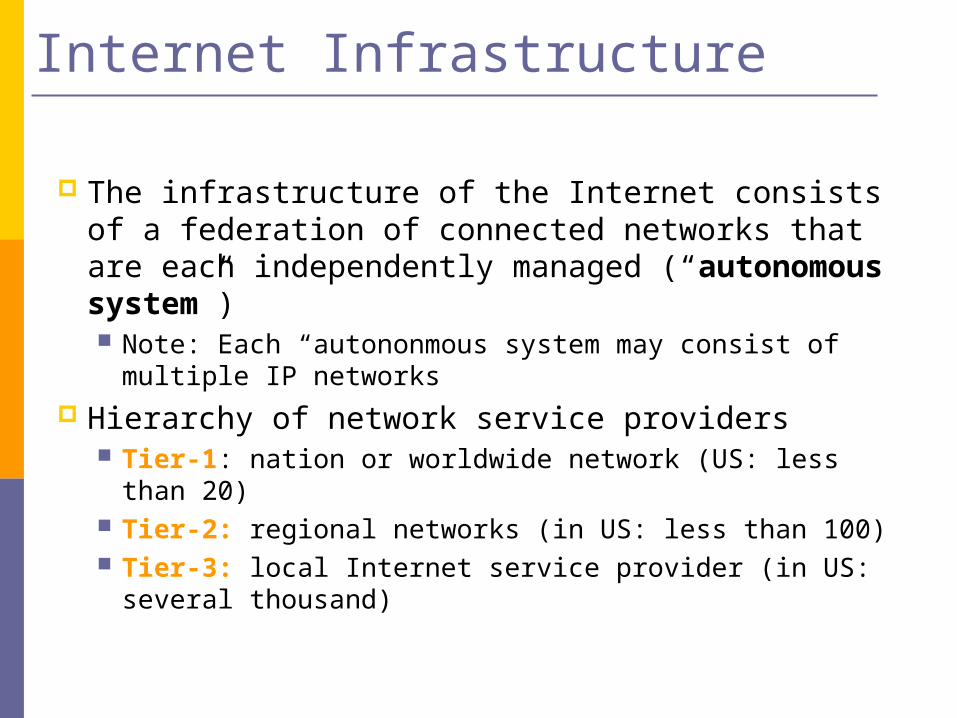
The infrastructure of the Internet consists of a federation of connected networks that are each independently managed (“autonomous system”) Note: Each “autononmous system may consist of
multiple IP networks Hierarchy of network service providers
Tier-1: nation or worldwide network (US: less than 20) Tier-2: regional networks (in US: less than 100) Tier-3: local Internet service provider (in US: several
thousand)
Internet Infrastructure
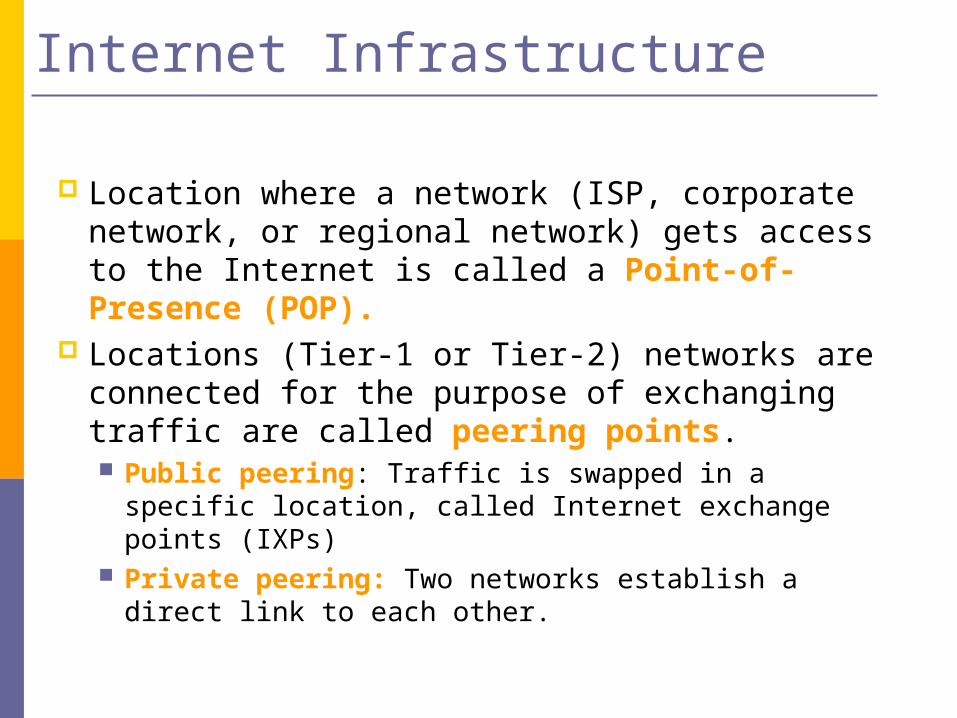
Location where a network (ISP, corporate network, or regional network) gets access to the Internet is called a Point-of-Presence (POP).
Locations (Tier-1 or Tier-2) networks are connected for the purpose of exchanging traffic are called peering points. Public peering: Traffic is swapped in a specific
location, called Internet exchange points (IXPs) Private peering: Two networks establish a direct link
to each other.
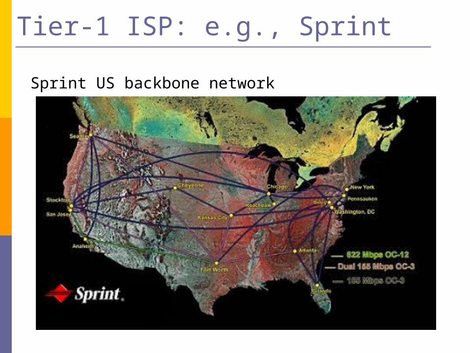
Tier-1 ISP: e.g., Sprint
Sprint US backbone network
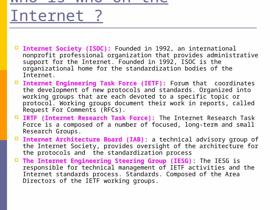
Who is Who on the Internet ?
Internet Society (ISOC): Founded in 1992, an international nonprofit professional organization that provides administrative support for the Internet. Founded in 1992, ISOC is the organizational home for the standardization bodies of the Internet.
Internet Engineering Task Force (IETF): Forum that coordinates the development of new protocols and standards. Organized into working groups that are each devoted to a specific topic or protocol. Working groups document their work in reports, called Request For Comments (RFCs).
IRTF (Internet Research Task Force): The Internet Research Task Force is a composed of a number of focused, long-term and small Research Groups.
Internet Architecture Board (IAB): a technical advisory group of the Internet Society, provides oversight of the architecture for the protocols and the standardization process
The Internet Engineering Steering Group (IESG): The IESG is responsible for technical management of IETF activities and the Internet standards process. Standards. Composed of the Area Directors of the IETF working groups.

Internet Standardization Process
Working groups present their work i of the Internet are published as RFC (Request for Comments).
RFCs are the basis for Internet standards. Not all RFCs become Internet Standards ! (There are
>3000 RFCs and less than 70 Internet standards A typical (but not only) way of standardization is:
Internet Drafts RFC Proposed Standard Draft Standard (requires 2 working implementation) Internet Standard (declared by IAB)
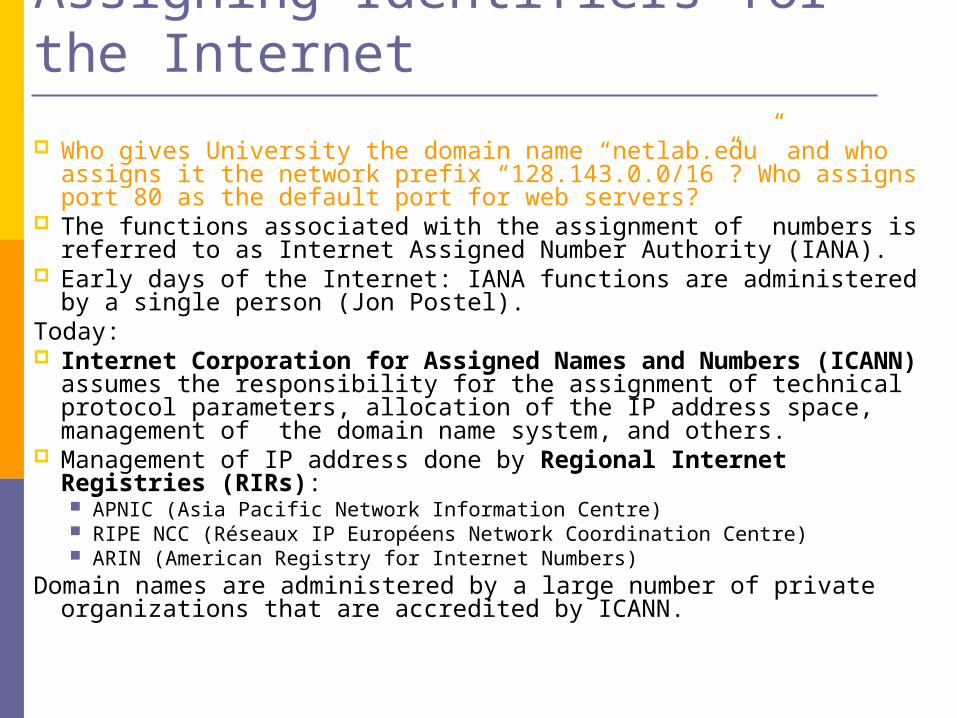
Assigning Identifiers for the Internet
Who gives University the domain name “netlab.edu” and who assigns it the network prefix “128.143.0.0/16”? Who assigns port 80 as the default port for web servers?
The functions associated with the assignment of numbers is referred to as Internet Assigned Number Authority (IANA).
Early days of the Internet: IANA functions are administered by a single person (Jon Postel).
Today: Internet Corporation for Assigned Names and Numbers (ICANN)
assumes the responsibility for the assignment of technical protocol parameters, allocation of the IP address space, management of the domain name system, and others.
Management of IP address done by Regional Internet Registries (RIRs): APNIC (Asia Pacific Network Information Centre) RIPE NCC (Réseaux IP Européens Network Coordination Centre) ARIN (American Registry for Internet Numbers)
Domain names are administered by a large number of private organizations that are accredited by ICANN.
Summary
Layered Internet architecture Reduce complexity Higher layer views lower layer as service provider Application layer, transport layer, network layer, and
link layer