Embed Size (px)
Citation preview
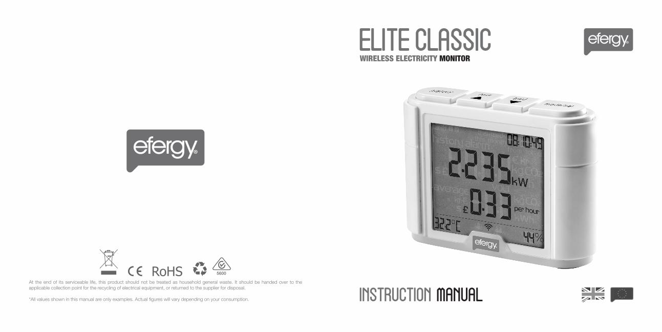

INTRODUCTIONSAFETY
IN THE BOX
HARDWARE INSTALLATION Prior to Installation Mounting Individual or Multiple Circuits Mounting Individual or Multiple Circuits Installing the CT Sensor Installing the CT Sensor
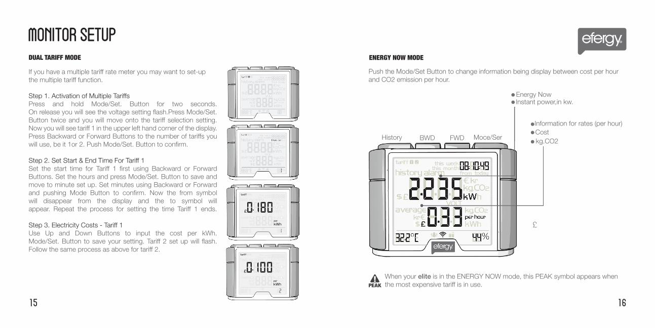
MONITOR SETUP Linking Transmitter and Monitor Setting the Time & Date Setup Instructions Setup Instructions Dual Tariff Mode Energy Now Mode History Mode
FAQsTECHNICAL INFORMATIONINSTALLATION NOTESTECHNICAL NOTES FOR ELECTRICIAN
23
5
678910
11121314151617
18191920


Auxilary Cable1
23
4
12
3 4Fig. 1
12
34
Fig. 2

Fig. 4 Fig. 5

Transmission Signal Symbol
Dashes indicate signals not linked
Wireless energy monitor link button
Hold for 2 seconds
historybackward
forwardmode/set


Model Name Model NumberFrequency Transmission Time Transmission Range Sensor Voltage Range Measuring CurrentMemory
efergy elite ELITE-2.0-UK433.5MHz6, 12 or 18 Sec230 - 328ft (40-70m)110 - 400V50mA - 90A 64K
120V, 3 Wire, Single Phase 120240V, 3 Wire, Single Phase 240
120/ 208V, 3 Wire, 2 Phases of a 3 Phase 120/208V Three wires phase 1 live, phase 2 live, Grid 120V is live to neutral and 208 is phase 120to phase. Assume unbalanced load. 2 CT Sensors
120/ 208V, 4 Wire, 3 Phases, Balanced Load Three phase live, phase 2 live - Neutral, where 120V is phase to neutral and 208V 208is phase to phase. 1 CT Sensor
120/ 208V, 4 Wire, 3 Phases, Unbalanced Load The display does not recognize unbalanced loads in this configuration. The degree 120of accuracy will be relative to the amount of unbalanced current. 3 CT Sensors
208V, 3 Phase Delta Balanced Load 208
277/ 480V, 4 Wire, 3 Phases, Balanced Load Three phase live + neutral, where 277V is phase to neutral and 480V is phase to 480phase. 1CT Sensor
277/ 480V, 4 Wire, 3 Phases, Unbalanced Load Three phase live + neutral, where 277V is phase to neutral and 480V is phase to phase. The display does not recognize unbalanced loads in this configuration. 277The degree of accuracy will be relative to the amount of unbalanced current. 3 CT Sensors
230/ 400V, 4 Wire, 3 Phases, Balanced Load Three phase live + neutral, where 230V is phase to neutral and 400V is phase to 400phase. 1CT Sensor
347/ 575V, 3 Phase, Balanced Load. 1CT Sensor 580
347/ 575V, 3 Phase, Unbalanced Load. The display does not recognize unbalanced loads in this configuration. The degree 350of accuracy will be relative to the amount of unbalanced current. 3 CT Sensors
ELECTRICITY SYSTEM VOLT SETTING