Embed Size (px)
Citation preview

Introduction
SPS07-STMAN1-E
®�

© 2007–2012 Inter-Industry Conference On Auto Collision Repair 2
INTRODUCTION
Topic A. Obligations To The Customer And Liability
The Collision Repair Industry has an obligation to correctly repair the customer’s vehicle. Collision repairs must be performed using:
recommended or tested procedures from vehicle makers, I‑CAR, and other research and testing organizations.
quality replacement parts and materials. repair processes and parts as written and agreed
upon in the repair order.
If items on the repair agreement are not consistent with the repair order, it can be considered fraud.
Performing proper collision repairs requires using parts and procedures that keep remaining warranties intact. Collision repairs must restore:
safety. structural integrity. durability. performance. fit. finish.
Throughout the damage analysis and repair process, the repairer and insurer must communicate with each other and the customer. They must be in agreement with each other and the customer on how repairs will be performed. The customer must be informed of any changes in the repair plan from the original repair agreement and explain the changes and why they have to be made.
To reduce liability, make sure that all repairs are performed thoroughly and correctly. Perform the repairs as listed in the damage report and have documentation of required repairs available for customers. Be sure of the proper procedures. Technicians are considered the experts and are expected be knowledgeable on how to perform a quality repair.
Liability insurance that covers the repair facility may not always cover all damages. For example, the policy may not cover faulty repairs, leaving liability responsibility completely on the facility. A shop owner may find that repair facility liability coverage may not cover the full amount awarded in a lawsuit. The shop owner would have to pay the difference.

© 2007–2012 Inter-Industry Conference On Auto Collision Repair 3
It is difficult to reduce the risk of liability exposure. The part that the repairer can control is the chance of being found at fault. Chances can be minimized by using recommended or tested procedures from the vehicle makers, I‑CAR, or other research and testing organizations. It is also important to use quality replacement parts and materials that restore fit, finish, durability, and perform at least as well as the original. Lastly, keep thorough records that document the repair process.
Keeping thorough records includes more than recording the date, mileage, and pre‑existing damage. Record keeping also includes:
making sure all notes are legible. verifying the repairs that were made or not
made. having the customer sign a waiver for repairs
that they do not want performed. Repairers must determine their liability on not repairing safety systems such as restraint and anti‑lock brake systems.
keeping computer printouts or worksheets on file showing wheel alignment readings or vehicle dimensions before and after repairs.
keeping scan tool printouts and records of computer codes for airbag, anti‑lock brake, emission, and powertrain control module (PCM) systems.
attaching the OEM procedure printout to the vehicle repair order.
keeping receipts for all sublet work performed.
Steel Unitized Structures
Technologies And Repair
Text
book
®�

Steel Unitized Structures Technologies And Repair v.9.4© 2007–2012 Inter-Industry Conference On Auto Collision Repair
2
This material provides general directions for collision damage repair using tested, effective procedures. Follow-ing them will help assure the reliability of the repair.
I-CAR cannot accept responsibility for any individual repair, nor can it warrant to the quality of such repair. Anyone who departs from the instructions in this program must first establish that neither personal safety nor the integrity of the repair of the vehicle is compromised by the choice of methods, tools, or supplies.
I-CAR does not endorse or recommend any brands or makes of vehicles, repair equipment and supplies or other products. The appearance of various makes and brand names in any I-CAR material is purely coincidental and is based on the availability of those products at the time of production.
All recommendations presented in this program are based upon research programs or upon tests conducted by laboratories, manufacturers, or selected collision repair facilities. If performed as outlined, these recom-mendations will provide the basis for a thorough, professional repair.
© 2007–2012 by the Inter-Industry Conference On Auto Collision Repair (I-CAR) All Rights Reserved
IMPORTANT NOTICE

Steel Unitized Structures Technologies And Repair v.9.4© 2007–2012 Inter-Industry Conference On Auto Collision Repair
3
Module 1–Steel Strength And Unitized Structures Repair ...................................................................4A. Vehicle Features And Functions .............................................................................................................. 4B. Steel Strength ............................................................................................................................................... 8C. Mechanical Properties Of Steel .............................................................................................................16D. Heat Affects On Steel ..............................................................................................................................20E. Identifying Steel Types ..............................................................................................................................21F. Metallurgical Designation .........................................................................................................................23G. Review .........................................................................................................................................................32
Module 2–New Construction Processes ............................................................................................. 33Topic A. Front Structures ..............................................................................................................................33Topic B. Laminated Steel ..............................................................................................................................34Topic C. Tailored Blanks ................................................................................................................................38Topic D. Hydroformed Parts ........................................................................................................................41Topic E. Multiple Layer Construction .........................................................................................................42Topic F. Foams ................................................................................................................................................46Topic G. Weld Bonding.................................................................................................................................49Topic H. MIG Brazing ...................................................................................................................................50Topic I. Summary ............................................................................................................................................51
CONTENTS

Steel Unitized Structures Technologies And Repair v.9.4–Module 1© 2007–2012 Inter-Industry Conference On Auto Collision Repair
4
MODULE 1–STEEL STRENGTH AND UNITIZED STRUCTURES REPAIR
Topic A. Vehicle Features And Functions
A-2 Like most new vehicles, this late model Mercedes Benz CLK sedan is loaded with safety and convenience features that add weight to the vehicle.
New vehicles have many features and functions that the vehicles of just a decade or less ago did not. This includes:
n additional electronics, including an increasing number of computers and the wiring associated with them.
n increased noise, vibration, and harshness (NVH) control.
n increased collision energy management. The struc-tures of late model vehicles have been designed with collision energy management and occupant protection as one of the primary goals.
n additional restraints and other safety systems for increased occupant protection in collisions.
All of these added features and functions add weight to the vehicle.
A-3 New unitized structures are designed to maximize occupant protec-tion during collisions.
Passive safety for unitized structures includes:
n controlling collision energy forces for optimized occupant protection. This is done by designing the structure to optimize both collision energy absorption and collision energy transfer charac-teristics.
n maintaining the integrity of the passenger com-partment in collisions. This is critical to limit intrusion injuries to the vehicle occupants. The passenger compartment is the strongest portion of the vehicle.

Steel Unitized Structures Technologies And Repair v.9.4–Module 1© 2007–2012 Inter-Industry Conference On Auto Collision Repair
5
Dodge Caliber
A-4 The deformation of this front frame rail is an example of how unitized structures absorb collision energy during collisions.
Collision energy absorption:
n is achieved through deformation of parts of the structure. As a part deforms or crushes, energy is dissipated. This energy absorption through part deformation is designed into the structure by including collapse or crush zones in the part. As parts crush and energy is absorbed the decelera-tion rate of the vehicle is also slowed down. This helps in controlling g-forces experienced by the vehicles occupants.
n occurs mostly in the front or rear section of the vehicle, though other areas of the vehicle may aide in the process to a lesser extent. Part deformation in the center section of the vehicle is limited to help maintain the shape of the pas-senger compartment and limit intrusion injuries to vehicle occupants.
Front
Side
Rear
Side
A-5 These illustrations show how collision energy is transferred through the structure of a vehicle during a collision.
Collision energy transfer:
n characteristics are incorporated into the struc-ture through build geometry and increased part strength.
n helps to disperse energy around the passenger compartment and other critical areas of the vehicle.
n occurs in the stronger portions of the frame rails, closer to the passenger compartment, and in the pillars and roof rails.
Steel Unitized Structures Technologies And Repair v.9.4–Module 1© 2007–2012 Inter-Industry Conference On Auto Collision Repair
6
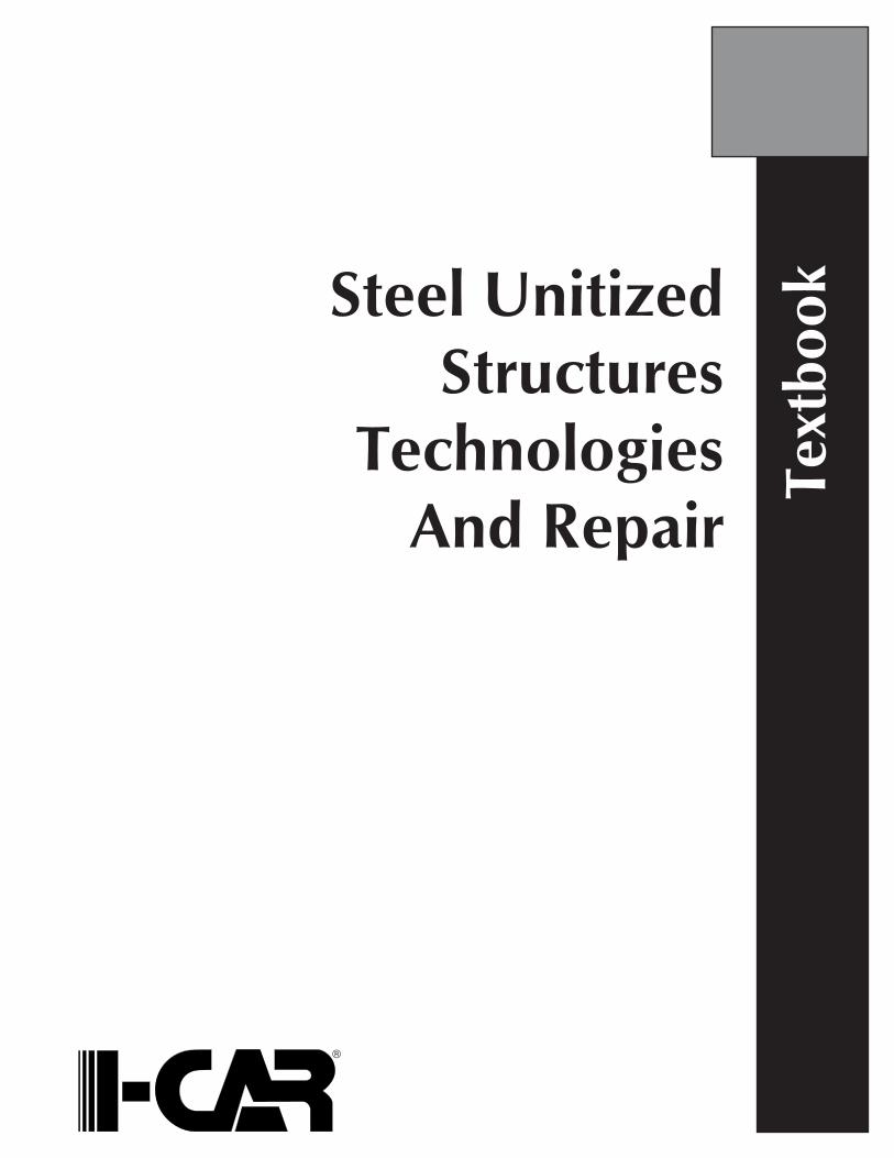
A-6 This offset-front crash test was done to analyze the collision energy management of the vehicles during a common frontal collision.
Collision energy management during frontal colli-sions:
n includes the front portions of the long front frame rails crushing to absorb collision energy and slow the rate of vehicle deceleration. The space between the passenger compartment and the front of the vehicle is where the majority of part deformation and energy absorption is designed to take place in a frontal collision.
n requires the stronger portions of the vehicle structure close to, and including the passenger compartment, to maintain their shape and transfer the collision energy throughout the entire vehicle structure through the rocker panel, roof rails, pillars, and floor pan. The passenger compart-ment is designed to maintain its size and shape. Damage may radiate into weaker parts of the core structure that do not allow a reduction of area inside the passenger compartment.
Saab 9-3
A-7 The center section of the B-pillar on this vehicle maintained its shape during a side collision, helping to avoid intrusion injuries to the vehicle occupants.
Collision energy management during side-impact collisions:
n includes very limited part movement and crush. Because of the limited space between the side of the vehicle and the passengers, the pillars have to be very strong and have minimal deflection in the center portions. B-pillars on newer vehicles are designed to maintain their shape in the center and deflect in very small amounts at the top and bottom where they connect to the rocker panels and roof structure.
n is mostly done through energy transfer. The side pillars transfer energy into the strong rocker panels, floor reinforcements, and roof structure where it is dispersed throughout the passenger compartment and absorbed in softer parts of the structure. Collision energy is also dissipated by the vehicle sliding sideways on the road surface.

Steel Unitized Structures Technologies And Repair v.9.4–Module 1© 2007–2012 Inter-Industry Conference On Auto Collision Repair
7
Dodge Caliber
A-9 This Dodge Caliber uses high-strength and ultra-high-strength steel, as well as new construction methods to maximize passenger safety and comfort while controlling vehicle weight.
How are newer steel unitized vehicles designed to provide maximum occupant protection and com-fort while dealing with the increased weight these features add?
Ford Mustang
A-8 During a rear collision, the rear portion of this vehicle deformed significantly behind the passenger compartment to absorb collision energy.
Collision energy management during rear-impact collisions:
n includes the long, rear frame rails and body structure behind the passenger compartment crushing to absorb collision energy.
n requires the stronger portion of the structure close to the passenger compartment to maintain its shape and transfer collision energy throughout the structure and around the passenger compart-ment and fuel tank.
Rear structures tend to be made of lower strength steels when compared to front structures and will typically collapse more as a result. Crossmembers and reinforcements near the fuel tank and passenger compartment use higher strength steel to resist col-lapse and transfer energy to portions of the structure away from passengers and the fuel tank.

Steel Unitized Structures Technologies And Repair v.9.4–Module 1© 2007–2012 Inter-Industry Conference On Auto Collision Repair
8
Buick Enclave
B-1 The inner B-pillar on this Buick Enclave uses ultra-high-strength steel reinforcements to provide maximum strength without adding consider-able weight to the vehicle.
In recent years, new steel types have been designed that allow:
n parts to be made stronger without the addition of reinforcements.
n parts to be made thinner and lighter, but still have the same strength.
n for added control of collision energy manage-ment. Mechanical properties of new steels allow the collision energy management of a part to be fine-tuned for added energy absorption and transfer as needed.
B-2 This tensile test machine is used to determine the ultimate tensile strength of metal samples.
Steel types can be classified by the:
n strength of the steel. Steel strength may be listed as tensile strength, yield strength, or both.
n mechanical properties of the steel. The mechani-cal properties include those things that determine the workability of the metal.
n metallurgical designation or name of the steel. The metallurgical designation is determined by the build process and alloy of the steel.
Topic B. Steel Strength

Steel Unitized Structures Technologies And Repair v.9.4–Module 1© 2007–2012 Inter-Industry Conference On Auto Collision Repair
9
Tensile Strength (MPa)
70
60
50
40
30
20
10
00 200 500 800 1100 1400 1700
Tota
l Elo
ng
atio
n (
%)
MARTDP-CP
CMn
BH
IS
Ultra-High-StrengthSteels (> 700 MPa)
High-StrengthSteels
Low-StrengthSteels
(< 270 MPa)
IF-HS
IF
MILD
HSLA
TRIP
B-3 This chart shows different types of automotive steels and the basic strength categories that they fall into.
Steel strength classifications for vehicles include:
n mild steel. Mild steel is typically any steel that has less than 270 MPa tensile strength and 210 MPa yield strength.
n high-strength steel (HSS). HSS typically has a tensile strength between 270 and 700 MPa and a yield strength between 210–550 MPa.
n ultra-high-strength steel (UHSS), which has a ten-sile strength over 700 MPa and a yield strength over 550 MPa.
B-5 A molten steel mixture is being poured from one vessel to another during the steel making process.
Increasing the strength of steel can be done by:
n altering the manufacturing process. The amount and rate of heating and cooling of the steel, and the pressures used as it is manufactured can have a drastic effect on the strength of the finished steel.
n alloying of the steel. The percentage of carbon mixed into the iron that steel is made from is one of the main contributing factors to its final strength. Other metals are also added in small amounts to alter the properties and strength of the steel.
Tensile Strength (MPa)
70
60
50
40
30
20
10
00 200 500 800 1100 1400 1700
Tota
l Elo
ng
atio
n (
%)
MARTDP-CP
HSLACMn
IF
MILD
BH
IF-HS
IS
AHSS
TRIP
B-4 This chart highlights the steels that may be called advanced high-strength steel (AHSS).
Newer types of high-strength steel, especially those in the upper strength ranges, may be called advanced high-strength steel (AHSS).
Steel Unitized Structures Technologies And Repair v.9.4–Module 1© 2007–2012 Inter-Industry Conference On Auto Collision Repair
10
900
800
700
600
500
400
300
100
00.1 1 10 10 10 10 10
200
Time (Seconds)
Tem
per
atu
re (
C)
(Austenite)
Pearlite
BaniniteBaninite
Martensite
Martensite
2 3 4 5
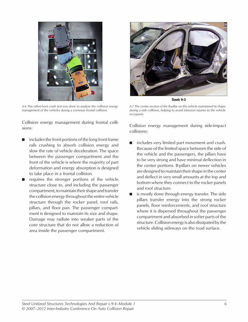
B-7 This temperature-to-time graph shows how the cooling rate affects the final phase and composition of steel.
Austenite phase steels are stronger than ferrite phase steels and are:
n made by heating the steel above 727oC (1,340oF) where more carbon atoms dissolve in the iron atoms of the structure. The amount of carbon that remains dissolved in the iron is affected by rate of heating and cooling, as the carbon falls out of the solution as it cools. The faster the steel is cooled, the more carbon atoms that will remain suspended with the iron atoms.
n a face-centered cubic crystal structure. The spaces between the iron atoms in a face-centered cubic crystal structure are just large enough to hold the carbon atoms.
Body Centered(9 Atoms)
B-6 This illustration shows the basic body-centered cubic structure of ferrite phase or mild steels.
Ferrite phase steels are typically considered mild steels and:
n have a body-centered cubic crystal structure. The spaces between the iron atoms in a body-centered cubic crystal structure are too small to hold carbon atoms.
n have a very small percentage of dissolved carbon in the iron base.
n are the softest and most basic of the steel struc-tures.
Steel Unitized Structures Technologies And Repair v.9.4–Module 1© 2007–2012 Inter-Industry Conference On Auto Collision Repair
11
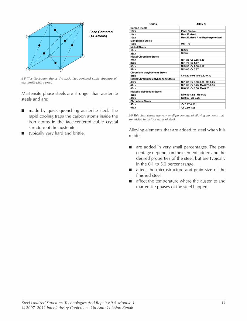
Face Centered(14 Atoms)
B-8 This illustration shows the basic face-centered cubic structure of martensite phase steel.
Martensite phase steels are stronger than austenite steels and are:
n made by quick quenching austenite steel. The rapid cooling traps the carbon atoms inside the iron atoms in the face-centered cubic crystal structure of the austenite.
n typically very hard and brittle.
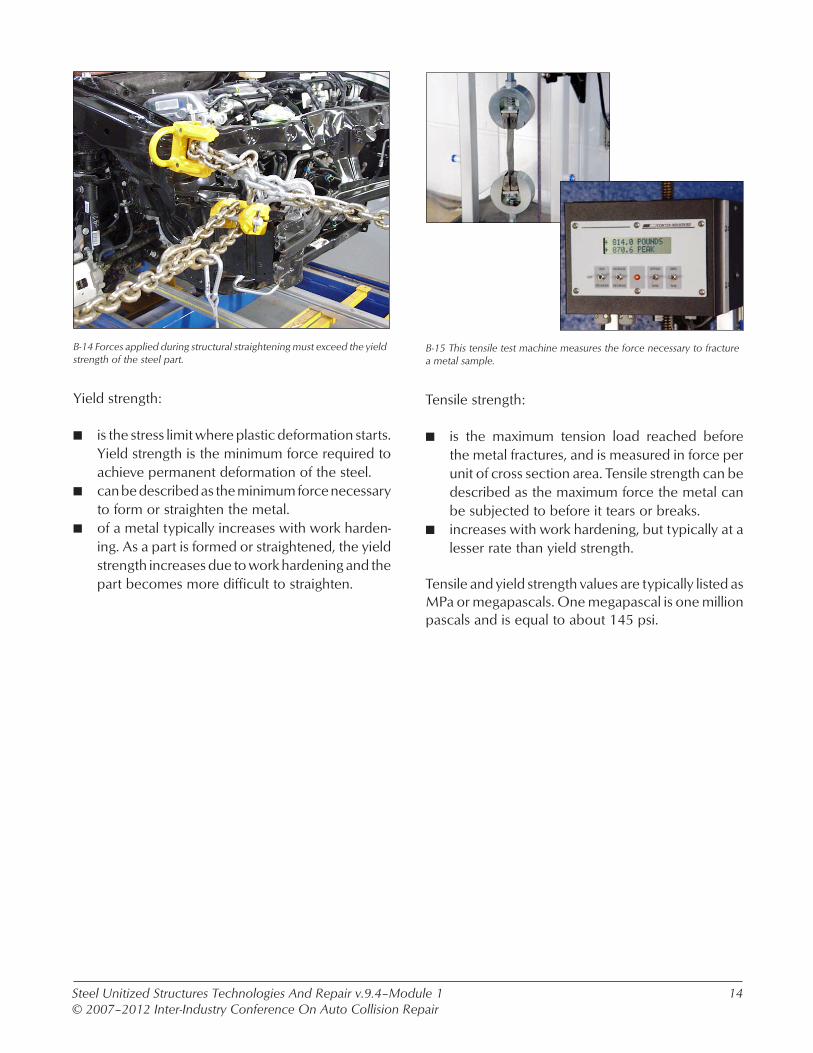
Carbon SteelsPlain CarbonResulfurizedResulfurized And Rephosphorized
23xx25xx
31xx32xx33xx34xx
41xx
43xx47xx86xx
46xx48xx
50xx51xx
13xx Mn 1.75
Ni 3.5Ni 5.0
Ni 1.25 Cr 0.65-0.80Ni 1.75 Cr 1.07Ni 3.50 Cr 1.50-1.57Ni 3.00 Cr 0.77
Cr 0.50-0.95 Mo 0.12-0.30
Ni 1.82 Cr 0.50-0.80 Mo 0.25Ni 1.05 Cr 0.45 Mo 0.20-0.35Ni 0.55 Cr 0.50 Mo 0.20
Ni 0.85-1.82 Mo 0.20Ni 3.50 Mo 0.25
Cr 0.27-0.65Cr 0.80-1.05
10xx11xx12xxManganese Steels
Nickel Steels
Nickel Chromium Steels
Nickel Chromium Molybdenum Steels
Nickel Molybdenum Steels
Chromium Steels
Chromium Molybdenum Steels
Series Alloy %
B-9 This chart shows the very small percentage of alloying elements that are added to various types of steel.
Alloying elements that are added to steel when it is made:
n are added in very small percentages. The per-centage depends on the element added and the desired properties of the steel, but are typically in the 0.1 to 5.0 percent range.
n affect the microstructure and grain size of the finished steel.
n affect the temperature where the austenite and martensite phases of the steel happen.

Steel Unitized Structures Technologies And Repair v.9.4–Module 1© 2007–2012 Inter-Industry Conference On Auto Collision Repair
12
B-10 The high-strength steel frame rail on this Honda Accord cracked when it was subjected to straightening forces.
As the strength of steel increases, it typically becomes:
n harder. The Rockwell hardness of steel typically increases as the tensile strength is increased. This makes the steel less workable and harder to form or straighten. The Rockwell hardness scale uses a testing method based on indention testing that measures the steels resistance to deformation.
n more brittle. The harder and stronger a steel is, the more prone it becomes to cracking when it is worked.
n more heat sensitive. The properties of HSS and UHSS are changed by heat much more than mild steels.
Honda Accord Front Frame Rail
B-11 The floor pan, cowl, and other outer closure panels that are color-coded black on this Volvo XC90 body shell are all made from mild steel.
Mild steel:
n is easily formed and is the most repairable of the steel types used in vehicle structures.
n typically can be heated during repairs as long as the limits for maximum temperature and time are observed.
n usage for structural parts is becoming limited on late model unitized structures.
Black–Mild Steel

Steel Unitized Structures Technologies And Repair v.9.4–Module 1© 2007–2012 Inter-Industry Conference On Auto Collision Repair
13
Yellow, Aqua, Blue–HSS
B-12 The yellow, aqua, and blue structural parts on this Volvo XC90 body shell are all made from various strengths and types of high-strength steel.
High-strength steel:
n is made in numerous different types. Each type may have unique mechanical properties and strength characteristics.
n is commonly used for structural parts because it can be thinner, lighter, and stronger than the same part made from a mild steel.
n is heat sensitive and is typically cold straightened. Heat can dramatically affect the strength and properties of HSS and therefore, is not recom-mended.
Red–UHSS
B-13 The parts of this Volvo XC90 body shell that are color coded red are made from boron-alloyed steel.
Ultra-high-strength steel:
n is very hard and strong.n usage is becoming more common. UHSS is typi-
cally used to reinforce areas and limit passenger compartment deformation in a collision.
n has its strength destroyed by heat.n is typically not straightened at all due to its strength
and the high degree of brittleness that it has.
Steel Unitized Structures Technologies And Repair v.9.4–Module 1© 2007–2012 Inter-Industry Conference On Auto Collision Repair
14
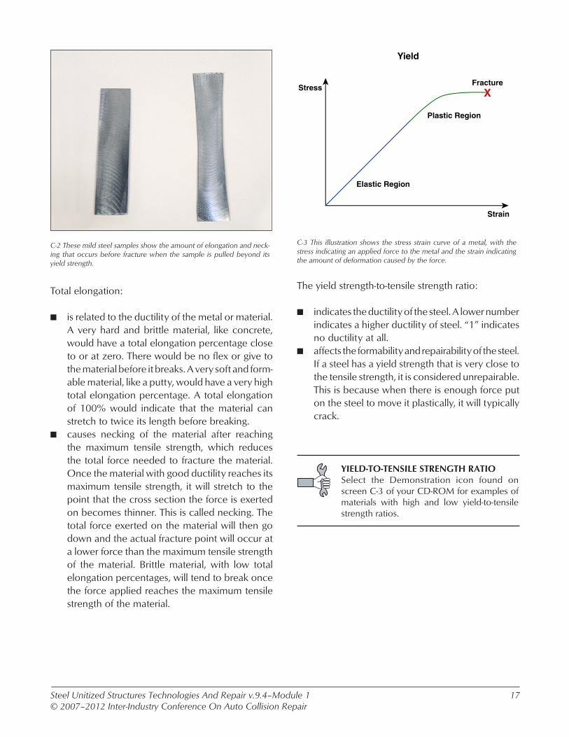
B-14 Forces applied during structural straightening must exceed the yield strength of the steel part.
Yield strength:
n is the stress limit where plastic deformation starts. Yield strength is the minimum force required to achieve permanent deformation of the steel.
n can be described as the minimum force necessary to form or straighten the metal.
n of a metal typically increases with work harden-ing. As a part is formed or straightened, the yield strength increases due to work hardening and the part becomes more difficult to straighten.
B-15 This tensile test machine measures the force necessary to fracture a metal sample.
Tensile strength:
n is the maximum tension load reached before the metal fractures, and is measured in force per unit of cross section area. Tensile strength can be described as the maximum force the metal can be subjected to before it tears or breaks.
n increases with work hardening, but typically at a lesser rate than yield strength.
Tensile and yield strength values are typically listed as MPa or megapascals. One megapascal is one million pascals and is equal to about 145 psi.

Steel Unitized Structures Technologies And Repair v.9.4–Module 1© 2007–2012 Inter-Industry Conference On Auto Collision Repair
15
B-16 The high-strength steel front frame rail on this Honda Accord is being initially straightened prior to its replacement.
What effects does the increased strength of the HSS and UHSS used in the parts of a unitized structure have on the collision repair process?
Honda Accord
B-17 The structural damage to this Honda Accord is greater than indicated by outward visual damage indicators.
The inclusion of higher strength steels in vehicle structures has led to changes in the way vehicles are damaged during collisions. These changes include:
n less passenger compartment deformation and fewer visible damage indicators.
n more collision energy transfer into the vehicle structure. Damage may radiate deeper into the structure and cause deformation of the softer parts of the structure, well away from the area of the primary damage.

Steel Unitized Structures Technologies And Repair v.9.4–Module 1© 2007–2012 Inter-Industry Conference On Auto Collision Repair
16
B-18 Straightening high-strength steel structural parts may require increased pulling force and additional anchoring to avoid collateral damage to other parts of the vehicle.
HSS and UHSS structural parts add some consider-ations to the structural straightening process. These considerations include that:
n increased force is required to straighten a dam-aged HSS part. Most UHSS parts that are dam-aged should not be straightened and will require replacement.
n kink vs. bend may not apply to damaged parts made of higher strength steels. The kink vs. bend rule was made when most structural parts were made of mild steel, or conventional high-strength steel that falls into the lower strength range of the group. With newer advanced HSS and UHSS, even minor visible damage may be hard to repair.
n collateral damage to anchoring points or attached parts is more of a concern. The part that is being straightened may be of a higher strength than the parts that it is attached to. This will cause the pulling forces to be transferred to the lower strength parts, which could cause unwanted damage. Careful monitoring during the straightening process can help avoid causing collateral damage. Additional anchoring points will also help to avoid collateral damage. Another helpful technique is to use heat when stress relieving. However, this should only be done on HSS and UHSS parts that are going to be replaced.
Tensile Strength (MPa)
70
60
50
40
30
20
10
00 200 500 800 1100 1400 1700
To
tal E
lon
gat
ion
(%
)
MARTDP-CP
TRIP
HSLA
CMn
MILD
BH
IF-HSIS
Ultra-High-StrengthSteels (> 700 MPa)
Load Transfer/Crush Resistance
EnergyAbsorption
IF
C-1 This chart shows the basic strength ranges where energy absorption and energy transfer occur.
Mechanical properties of steel include:
n total elongation, which is the percentage that the metal will stretch before it fractures or breaks.
n the work hardening exponent, which is the rate that the metal work hardens.
n the toughness of the metal. Toughness is a com-bination of strength and ductility. For a metal to be considered very tough, it has to have high strength along with a high degree if ductility. Many very strong metals are not considered tough because they are very brittle, while many of the very ductile metals are not tough because they lack strength.
Topic C. Mechanical Properties Of Steel
BRITTLENESS OF ULTRA-HIGH STRENGTH STEELRefer to screen B-19v of your CD-ROM for a video on the brittleness of ultra-high strength steel.
Steel Unitized Structures Technologies And Repair v.9.4–Module 1© 2007–2012 Inter-Industry Conference On Auto Collision Repair
17
C-2 These mild steel samples show the amount of elongation and neck-ing that occurs before fracture when the sample is pulled beyond its yield strength.
Total elongation:
n is related to the ductility of the metal or material. A very hard and brittle material, like concrete, would have a total elongation percentage close to or at zero. There would be no flex or give to the material before it breaks. A very soft and form-able material, like a putty, would have a very high total elongation percentage. A total elongation of 100% would indicate that the material can stretch to twice its length before breaking.
n causes necking of the material after reaching the maximum tensile strength, which reduces the total force needed to fracture the material. Once the material with good ductility reaches its maximum tensile strength, it will stretch to the point that the cross section the force is exerted on becomes thinner. This is called necking. The total force exerted on the material will then go down and the actual fracture point will occur at a lower force than the maximum tensile strength of the material. Brittle material, with low total elongation percentages, will tend to break once the force applied reaches the maximum tensile strength of the material.
Strain
Stress
Elastic Region
Plastic Region
FractureX
Yield
C-3 This illustration shows the stress strain curve of a metal, with the stress indicating an applied force to the metal and the strain indicating the amount of deformation caused by the force.
The yield strength-to-tensile strength ratio:
n indicates the ductility of the steel. A lower number indicates a higher ductility of steel. “1” indicates no ductility at all.
n affects the formability and repairability of the steel. If a steel has a yield strength that is very close to the tensile strength, it is considered unrepairable. This is because when there is enough force put on the steel to move it plastically, it will typically crack.
YIELD-TO-TENSILE STRENGTH RATIOSelect the Demonstration icon found on screen C-3 of your CD-ROM for examples of materials with high and low yield-to-tensile strength ratios.

Steel Unitized Structures Technologies And Repair v.9.4–Module 1© 2007–2012 Inter-Industry Conference On Auto Collision Repair
18
200
300
400
500
600
700
800
Strain Rate (MPa)
Tim
elin
e S
trai
n (
MP
a) 900
1000
1200
0.001 0.01 0.1 1 10 100 1000 10000
200
300
400
500
600
700
800
Strain Rate (MPa)
Yield Strength
Tensile Strength
Tim
elin
e S
trai
n (
MP
a) 900
1000
1200
0.001 0.01 0.1 1 10 100 1000 10000
DP 500/800
DP 350/600
TRIP 350/600
HSLA 350/450
C-4 These charts show the difference between the work hardening effect on the yield and tensile strength of a steel.
Work hardening:
n describes the tendency of steel to increase in strength as it is worked. Work hardening affects both the yield and tensile strength of steel, but tends to affect yield strength at a higher rate than tensile strength. This leads to an increase in the brittleness of the steel as it is work hardened.
n rate differs by steel type. Some steel types work-harden at a much faster rate than others.
WORK HARDENINGSelect the Demonstration icon found on screen C-4 of your CD-ROM for an example of the affects of work hardening.
C-5 Resistance spot welding may be the preferred welding method on new unitized structures.
What considerations do the different mechanical properties of some newer steels add to the collision repair process?

Steel Unitized Structures Technologies And Repair v.9.4–Module 1© 2007–2012 Inter-Industry Conference On Auto Collision Repair
19
C-6 Because of the strength of the B-pillar, the side collision damage to this vehicle radiated deep into the floor pan.
Straightening considerations added by the different mechanical properties of newer steels include:
n that high yield-to-tensile strength ratios will cause cracks when straightening and because of this, parts made from steels with this property are not repairable. The closer the yield-to-tensile ratio is to “1,” the less likely it is that a part can be straightened without cracking.
n the high work hardening rate of some steels. Some of the newer steels used in unitized structures gain a good deal of their final strength through work hardening when parts are formed. Collision damage further work hardens the part and the straightening process adds to it again. This limits the amount of straightening that should be done because even if the part is restored to its correct shape, the mechanical properties and strength of the part may be significantly different than intended. Work hardening also tends to make a part more brittle and prone to cracking when straightened.
n the high heat sensitivity of HSS and UHSS.
GM STEEL REPAIRABILITY CHARTSelect the Demonstration icon found on screen C-6 of your CD-ROM for an example of the General Motors Steel Repairability Chart.
STRAIGHTENING HIGH-STRENGTH STEEL STRUCTURESRefer to screen C-7v of your CD-ROM for a video on structural straightening of a high-strength steel unitized structure.
Steel Unitized Structures Technologies And Repair v.9.4.a–Module 1© 2007–2012 Inter-Industry Conference On Auto Collision Repair
20
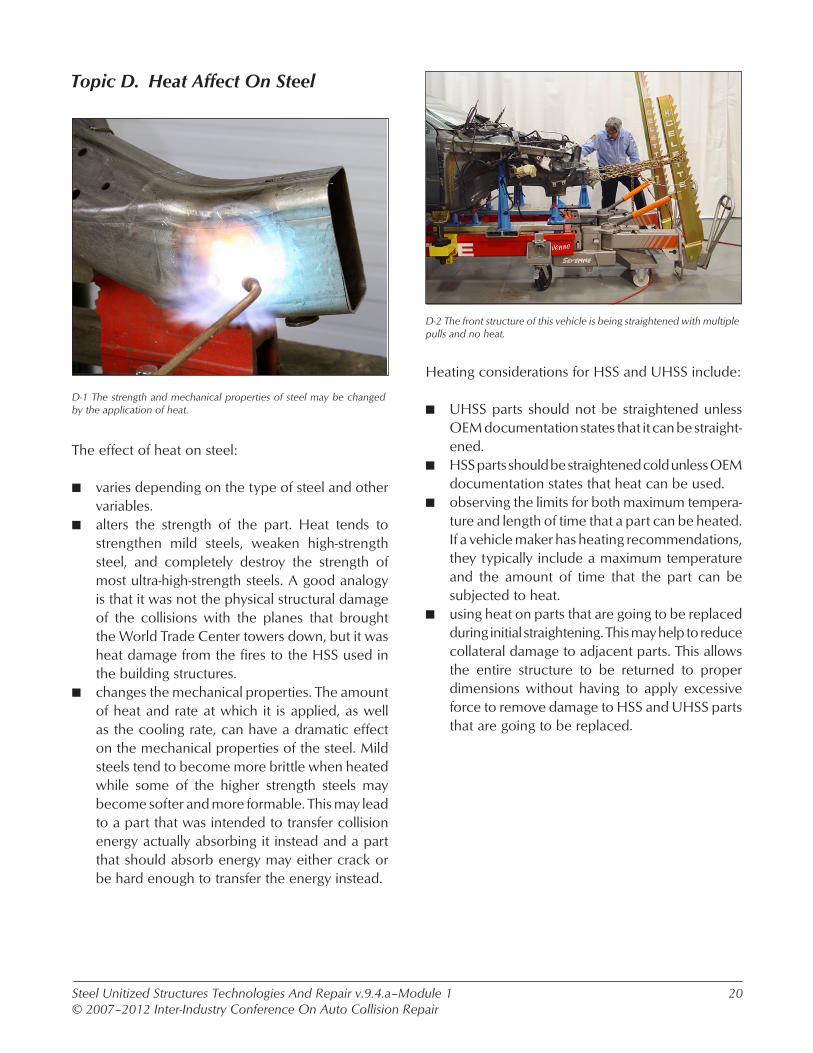
D-2 The front structure of this vehicle is being straightened with multiple pulls and no heat.
Heating considerations for HSS and UHSS include:
n UHSS parts should not be straightened unless OEM documentation states that it can be straight-ened.
n HSS parts should be straightened cold unless OEM documentation states that heat can be used.
n observing the limits for both maximum tempera-ture and length of time that a part can be heated. If a vehicle maker has heating recommendations, they typically include a maximum temperature and the amount of time that the part can be subjected to heat.
n using heat on parts that are going to be replaced during initial straightening. This may help to reduce collateral damage to adjacent parts. This allows the entire structure to be returned to proper dimensions without having to apply excessive force to remove damage to HSS and UHSS parts that are going to be replaced.
D-1 The strength and mechanical properties of steel may be changed by the application of heat.
The effect of heat on steel:
n varies depending on the type of steel and other variables.
n alters the strength of the part. Heat tends to strengthen mild steels, weaken high-strength steel, and completely destroy the strength of most ultra-high-strength steels. A good analogy is that it was not the physical structural damage of the collisions with the planes that brought the World Trade Center towers down, but it was heat damage from the fires to the HSS used in the building structures.
n changes the mechanical properties. The amount of heat and rate at which it is applied, as well as the cooling rate, can have a dramatic effect on the mechanical properties of the steel. Mild steels tend to become more brittle when heated while some of the higher strength steels may become softer and more formable. This may lead to a part that was intended to transfer collision energy actually absorbing it instead and a part that should absorb energy may either crack or be hard enough to transfer the energy instead.
Topic D. Heat Affect On Steel
Steel Unitized Structures Technologies And Repair v.9.4–Module 1© 2007–2012 Inter-Industry Conference On Auto Collision Repair
21
D-4 This GMA (MIG) weld shows the relatively wide heat-affect zone created by this welding process.
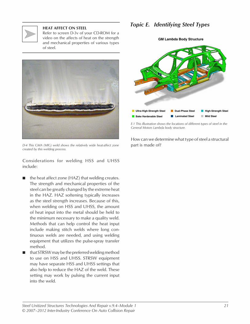
Considerations for welding HSS and UHSS include:
n the heat affect zone (HAZ) that welding creates. The strength and mechanical properties of the steel can be greatly changed by the extreme heat in the HAZ. HAZ softening typically increases as the steel strength increases. Because of this, when welding on HSS and UHSS, the amount of heat input into the metal should be held to the minimum necessary to make a quality weld. Methods that can help control the heat input include making stitch welds where long con-tinuous welds are needed, and using welding equipment that utilizes the pulse-spray transfer method.
n that STRSW may be the preferred welding method to use on HSS and UHSS. STRSW equipment may have separate HSS and UHSS settings that also help to reduce the HAZ of the weld. These setting may work by pulsing the current input into the weld.
HEAT AFFECT ON STEELRefer to screen D-3v of your CD-ROM for a video on the affects of heat on the strength and mechanical properties of various types of steel.
Topic E. Identifying Steel Types
Ultra-High-Strength Steel
Bake Hardenable Steel
High-Strength SteelDual-Phase Steel
GM Lambda Body Structure
Mild SteelLaminated Steel
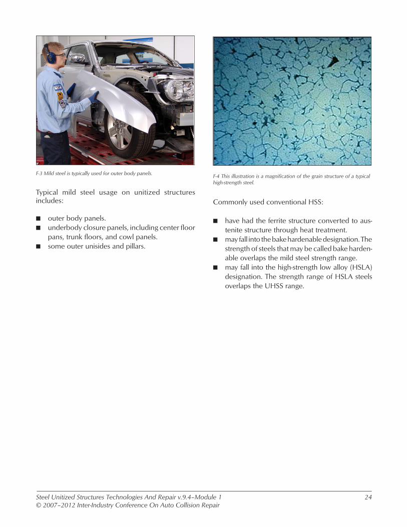
E-1 This illustration shows the locations of different types of steel in the General Motors Lambda body structure.
How can we determine what type of steel a structural part is made of?

Steel Unitized Structures Technologies And Repair v.9.4–Module 1© 2007–2012 Inter-Industry Conference On Auto Collision Repair
22
E-2 This vehicle maker service information shows the location of high-strength and ultra-high-strength steel in a vehicle’s structure.
Ways of identifying what type of steel a structural part is made of include:
n looking up the name or metallurgical designation of the steel in vehicle maker service information. Some collision repair manuals may include infor-mation on the types of steel used to make the structure and body panels of a vehicle.
n hardness testing to categorize as mild, HSS, or UHSS. Typically hardness testing will give numbers that can be compared to that of a known steel. This will allow the steel to be placed into a basic strength category based on this comparative data.
E-3 This technician is using bench top hardness testing equipment to determine the Rockwell hardness of a steel sample.
Hardness testing:
n may be done with fixed or bench mounted equip-ment that requires a small piece to be removed from the part.
n may be done with portable equipment. This allows testing without having to cut sections out of the vehicle parts.
n for comparison readings should be done with the same equipment. Do not compare results from one piece of equipment to those taken with a different piece of equipment.
VEHICLE MAKER STEEL IDENTIFICATION Select the Demonstration icon found on screen E-2 of your CD-ROM for an example of vehicle maker steel identification information.

Steel Unitized Structures Technologies And Repair v.9.4–Module 1© 2007–2012 Inter-Industry Conference On Auto Collision Repair
23
Tensile Strength (MPa)
70
60
50
40
30
20
10
00 200 500 800 1100 1400 1700
Tota
l Elo
ng
atio
n (
%)
MARTDP-CP
TRIP
HSLA
CMn
MILD
BH
IS
IF-HS
IF
F-1 This chart shows the metallurgical designations for the steels com-monly used in vehicle structures.
The metallurgical designation:
n is the scientific name given to different catego-ries of steel based on the build process or alloy content used.
n categorizes steels by common mechanical proper-ties. Typically steels that are made with the same build process and alloy content will have similar mechanical properties.
n only loosely categories the strength of the steel. The strength range within the categories can be very wide.
Topic F. Metallurgical Designation
F-2 This illustration is a magnification of the grain structure of a typical mild steel.
Names used for soft ferrite phase or mild steels include:
n conventional steels.n drawing steel (DS).n deep drawing steel (DDS).n interstitial free (IF).
These common mild steels have a very low carbon content and low tensile strengths but tend to have good ductility.
Steel Unitized Structures Technologies And Repair v.9.4–Module 1© 2007–2012 Inter-Industry Conference On Auto Collision Repair
24
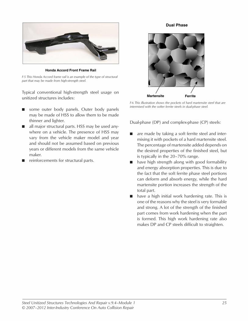
F-3 Mild steel is typically used for outer body panels.
Typical mild steel usage on unitized structures includes:
n outer body panels.n underbody closure panels, including center floor
pans, trunk floors, and cowl panels.n some outer unisides and pillars.
F-4 This illustration is a magnification of the grain structure of a typical high-strength steel.
Commonly used conventional HSS:
n have had the ferrite structure converted to aus-tenite structure through heat treatment.
n may fall into the bake hardenable designation. The strength of steels that may be called bake harden-able overlaps the mild steel strength range.
n may fall into the high-strength low alloy (HSLA) designation. The strength range of HSLA steels overlaps the UHSS range.
Steel Unitized Structures Technologies And Repair v.9.4–Module 1© 2007–2012 Inter-Industry Conference On Auto Collision Repair
25
Dual Phase
FerriteMartensite
F-6 This illustration shows the pockets of hard martensite steel that are intermixed with the softer ferrite steels in dual-phase steel.
Dual-phase (DP) and complex-phase (CP) steels:
n are made by taking a soft ferrite steel and inter-mixing it with pockets of a hard martensite steel. The percentage of martensite added depends on the desired properties of the finished steel, but is typically in the 20–70% range.
n have high strength along with good formability and energy absorption properties. This is due to the fact that the soft ferrite phase steel portions can deform and absorb energy, while the hard martensite portion increases the strength of the total part.
n have a high initial work hardening rate. This is one of the reasons why the steel is very formable and strong. A lot of the strength of the finished part comes from work hardening when the part is formed. This high work hardening rate also makes DP and CP steels difficult to straighten.
Honda Accord Front Frame Rail
F-5 This Honda Accord frame rail is an example of the type of structural part that may be made from high-strength steel.
Typical conventional high-strength steel usage on unitized structures includes:
n some outer body panels. Outer body panels may be made of HSS to allow them to be made thinner and lighter.
n all major structural parts. HSS may be used any-where on a vehicle. The presence of HSS may vary from the vehicle maker model and year and should not be assumed based on previous years or different models from the same vehicle maker.
n reinforcements for structural parts.
Steel Unitized Structures Technologies And Repair v.9.4–Module 1© 2007–2012 Inter-Industry Conference On Auto Collision Repair
26
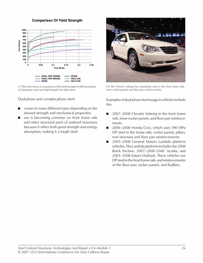
F-8 This Chrysler Sebring has dual-phase steel in the front frame rails, inner rocker panels, and floor pan reinforcements.
Examples of dual-phase steel usage in vehicles include the:
n 2007–2008 Chrysler Sebring in the front frame rails, inner rocker panels, and floor pan reinforce-ments.
n 2006–2008 Honda Civic, which uses 590 MPa DP steel in the frame rails, rocker panels, pillars, roof structure and floor pan reinforcements.
n 2005–2008 General Motors Lambda platform vehicles. The Lambda platform includes the 2008 Buick Enclave, 2007–2008 GMC Acadia, and 2005–2008 Saturn Outlook. These vehicles use DP steel in the front frame rails, and reinforcements of the floor pan, rocker panels, and B-pillars.
DUAL-TEN 780/800DUAL-TEN 590/600DQSK
DP500HSLA 340HSLA 550
Comparison Of Yield Strength
1000
True Strain
900
800
700
600
500
400300
200
100
00 0.05 0.150.1 0.2 0.25
Tru
e S
tres
s
F-7 This chart shows a comparison of the yield strength of different grades of dual-phase steel and high-strength low alloy steel.
Dual-phase and complex-phase steel:
n comes in many different types depending on the desired strength and mechanical properties.
n use is becoming common on front frame rails and other structural parts of unitized structures because it offers both good strength and energy absorption, making it a tough steel.

Steel Unitized Structures Technologies And Repair v.9.4–Module 1© 2007–2012 Inter-Industry Conference On Auto Collision Repair
27
F-10 This illustration is a magnification of the grain structure of a typical martensite steel.
Martensitic (MART) steels:
n have had the austenite structure converted to martensite structure.
n are very strong and hard with tensile strengths up to 1700 MPa.
n typically have low ductility, low total elongation percentages, and high yield strength-to-tensile strength ratios. This makes them hard to form and very difficult to straighten when damaged.
TRIP
Ferrite
RetainedAustenite
Martensite
• •
••
• •
• •
••
•
•
•
••
•
•
• •• •
••••••
•
•
•
•
•
•
•
•
••
••
••
••
• •
•
•
•
••
•
•
••••
••••••
•
•
•
•
•
•
•
•
••
••
••
••
• •
•
•
•
••
•
•
••••
••••••
•
•
•
•
•
•
•
•
••
••
•• •
•
••
•
•
•
••
•
•
•••
•
••••••
•
•
•
• •
•
•
•
• •
••
• •
• •
••
•
•
•
••
•
•
• •• •
••••••
•
•
•
•
•
•
•
•
••
•••
•
•
•
•
•
•
•
••••
••••••
••
•
••
•••
•
•
•
•
•
•
•
••••
••••••
••
•
••
•••
•
•
•
•
•
•
•
••••
••••••
••
•
•
••
••
•
•• •
•
• •
•
••
•
••
••
••
•••••
• •
••
•
•
•
•
•
•••
•
•
•
••
•
•
••
••
••
•••••
•
•
•
• •
••
•
•
•
• • •
••
•
•
•
•
• •
••
•
•
•
•
• •
••
•
•
•
•
• •
••
•
•
•
•
• •
••
•
•
•
•
• •
••
•
•
•
•
Bainite
F-9 This illustration shows the austenite and martensite steels that are intermixed with the ferrite steel in TRIP steel.
Transformation induced plasticity (TRIP) steel:
n is mostly a mixture of ferrite and austenite steels with a small amount of martensite steel. They are similar to DP and CP steels in that a percentage of it is a soft ferrite steel and the remainder is harder and stronger austenite steel and martensite steel.
n has tensile strengths in the 500–1050 MPa range.
n has similar mechanical properties as DP steels, but with slightly more ductility due to the pres-ence of austenite steel instead of the martensite steel which is used for making DP steel.

Steel Unitized Structures Technologies And Repair v.9.4.a–Module 1© 2007–2012 Inter-Industry Conference On Auto Collision Repair
28
F-12 Using pinchweld clamps in conjunction with fixtures helps to avoid collateral damage when straightening high-strength steel structures.
Collision repair considerations with AHSS steels such as DP and MART include:
n that parts made from them are very strong. They are designed to transfer energy and therefore, will transfer damage also. The high strength of these parts also makes straightening them difficult, and UHSS should not be straightened unless OEM documentation allows it. The high strength of parts made from these steels also increases the possibility of collateral damage to other parts of the vehicle when doing structural straightening.
n the location and function of parts that are typically made from these steels. These parts are typically in the main load-carrying path of the vehicle and have functions that are critical to protecting pas-sengers during collisions.
F-11 The inner and outer rocker panels and center floor pan crossmem-ber of this General Motors Lambda body structure are made from a martensitic steel.
The 2005–2008 General Motors Lambda platform vehicles use martensitic steel in the:
n rocker panels. Both the inner and outer rocker panels are made from martensitic steel, making a fully enclosed martensitic structure that maxi-mizes energy transfer in front, rear, and side collisions.
n center floor crossmember that runs between the lower B-pillars. This helps to transfer collision energy from one side of the passenger compart-ment to the other and keep the distance between the left and right side rocker panels from changing. In conjunction with a strong B-pillar, this helps avoid intrusion of the B-pillar into the passenger compartment.

Steel Unitized Structures Technologies And Repair v.9.4.a–Module 1© 2007–2012 Inter-Industry Conference On Auto Collision Repair
29
F-13 Advanced high-strength steel should not be heated during repairs.
Other considerations with DP and MART steels include:
n their heat sensitivity. Parts made from these steel should not be heated unless OEM documentation allows it or the part is going to be replaced. The HAZ when welding should also be considered. Use only enough heat to make a sound weld. Make practice welds that are destructively tested to verify the quality of the weld.
n the yield-to-tensile strength ratio. The closer the yield-to-tensile strength ratio is to “1,” the less repairable the steel is. A frame rail that cracks when pulled back into position is likely made from a steel with a high yield-to-tensile ratio. DP steels tend have a lower yield-to-tensile ratio than MART steels, but have high work hardening rates that increase the ratio as the part is damaged and repaired.
n that they may have high work hardening ratio. DP steels have good formability and energy absorp-tion, but tend to have high work hardening ratios. A steel with a high work hardening ratio cannot tolerate much straightening before it will crack, making anything more than minor straightening or moving of the position of these parts very dif-ficult.
Tensile Strength (MPa)
1: Before Heating
3: After Stamping And Quenching2: After Heating
Hot Stamping Affect On Strength And Ductility
70
60
50
40
30
20
10
00 200 500 800 1100 1400 1700
Tota
l Elo
ng
atio
n (
%)
1
2
3
F-14 This chart shows the strength change that a typical boron-alloyed steel goes through during the heating and quenching cycles of the hot stamping process.
Hot stamped parts:
n are made by stamping the sheet steel while it is very hot. The parts are then quenched to cool while still in the dies. This is done for two reasons, one to add increased formability with higher strength steels, and two, the heating and quenching process can actually increase the steel strength due to conversion of austenite to martensite.
n are typically made from boron-alloyed steels. The strength of a boron-alloyed steel part can increase as much as 250% during the hot stamping process, making a very strong part.
n are typically not galvanized because the high heat used during stamping would destroy the galvanized coating.

Steel Unitized Structures Technologies And Repair v.9.4–Module 1© 2007–2012 Inter-Industry Conference On Auto Collision Repair
30
F-16 The parts of this Volvo XC90 body shell that are color coded red are made from boron-alloyed steel.
Locations on unitized structures where boron-alloyed steel parts may be found include:
n door intrusion beams.n bumper reinforcements.n roof structures.n pillar inner panels and reinforcements.n rocker panel reinforcements.n rear body panels.
Examples include the 2003–2008 Volvo XC90, which uses boron-alloyed steel in the B-pillar reinforcement, center roof bow, and the inner rear body panel. The 2007–2008 Dodge Caliber uses boron-alloyed steel in the roof rail reinforcement and pillar reinforcements. The 2007–2008 Mercedes-Benz S-class uses a type of boron-alloyed steel called Usibor in the pillars of the vehicle.
F-15 This very strong and hard boron-alloyed B-pillar was cut using a chop saw with a special blade.
Boron-alloyed steel:
n is made by adding a small percentage of boron to the steel.
n is very strong and hard, with tensile strengths up to 1600 MPa.
n typically has low ductility, low total elongation percentages, and high yield strength-to-tensile strength ratios. It is typically recommended that boron alloyed steels not be straightened.
Boron-alloyed steels may be called by different names.

Steel Unitized Structures Technologies And Repair v.9.4–Module 1© 2007–2012 Inter-Industry Conference On Auto Collision Repair
31
F-17 A cutoff wheel is being used to cut through this boron-alloyed B-pillar on a Volvo XC90.
Boron-alloyed part considerations include that:
n they should not be sectioned without a vehicle maker procedure. Volvo has sectioning proce-dures for the boron-alloyed rear body panel and B-pillar reinforcement on the XC90.
n they should be cut with a cutoff wheel. A boron-alloyed steel part is harder than a saw blade and will remove the teeth from the blade almost immediately.
n rivet bonding may be recommended for their replacement. Mercedes-Benz has recommenda-tions to replace some of the Usibor parts on their vehicles using rivet bonding instead of welding.
Follow vehicle maker procedures for the replacement of damaged boron-alloyed steel parts.
SECTIONING BORON-ALLOYED PARTSRefer to screen F-18v of your CD-ROM for a video on sectioning parts made from boron-alloyed steel.
F-19 Grinding with a cutoff wheel or using a plasma cutter are two ways of removing spot welds from boron-alloyed steel.
Ways of removing spot welds from boron-alloyed parts include:
n grinding through the weld with a cut-off wheel.n using a plasma cutter. Some plasma cutters have
a setting that allows the cut to be made through only one layer of a multiple layer assembly. Check vehicle maker recommendations to ensure that they do not warn against the use of a plasma cutter.
n drilling the weld using a special hardened bit turning low rpm’s and remaining perpendicular to the weld. Welds can also be drilled from the backside or through the non-boron alloyed part. If you have access to the spot weld on the part that is not a boron-alloyed part, and it is acceptable to have holes in that part, this allows the weld to be drilled out in the conventional manner. Make sure that it will not be a problem having holes in the part that will remain on the vehicle before using this method.

Steel Unitized Structures Technologies And Repair v.9.4–Module 1© 2007–2012 Inter-Industry Conference On Auto Collision Repair
32
68%50% 38%
11%
19%
2%
3%
9%
2006 Honda Civic 2005 Honda Civic
HSS Usage Rate: 32%HSS Usage Rate: 50%
590440
340270
Grade
F-20 This illustration shows the difference in high-strength steel usage between the 2005 and 2006 Honda Civic.
The usage rate for HSS, UHSS, and AHSS in unitized vehicle structures is increasing every model year. An example of this is the Honda Civic. The 2005 Honda Civic structure was made up of 32% higher strength steels with 11% being DP 590. The 2006 Honda Civic structure is made up of 50% higher strength steels with 38% being DP 590.
Topic G. Review
ReviewRefer to screens G-1 and G-2 of your CD-ROM for review questions on steel strength and unitized structures repair.

Steel Unitized Structures Technologies And Repair v.9.4–Module 2© 2007–2012 Inter-Industry Conference On Auto Collision Repair
33
MODULE 2–NEW CONSTRUCTION PROCESSES
Topic A. Front Structures
Ford Taurus
A-2 The composite radiator core support on this vehicle bolts to the upper and lower front frame rails.
Composite radiator core supports are a new trend in vehicle design. Composite radiator core supports:
n allow for an open design front structure. The head-lamps, coolers, and the hood latch are typically attached and can be removed as an assembly with the composite radiator support assembly. Once the assembly is removed, it allows access to the drivetrain and other front structural parts.
n are typically light weight compared to their steel counterparts.
n bolt on to both the lower frame rails and the upper rails.
Nissan 350Z
A-3 Because it will break in a collision, the composite radiator core support on this vehicle will not transfer as much collision energy from side-to-side as a welded steel radiator core support.
Composite radiator supports:
n do not transfer as much collision energy from side-to-side as a welded steel radiator core sup-port. This may help to keep minor front damage isolated more to the side of the collision.
n are typically not repaired when damaged. Dam-aged composite radiator core supports are typi-cally replaced.

Steel Unitized Structures Technologies And Repair v.9.4–Module 2© 2007–2012 Inter-Industry Conference On Auto Collision Repair
34
Volvo S40
A-4 The crush tube on this front module assembly from a Volvo S40 is made from lower strength steel than the boron-alloyed inner bumper reinforcement.
Front crush tubes:
n may be found between the bumper reinforcement and front frame rails. They may be separate bolt-on parts or may be part of the bumper reinforcement assembly. This assembly may be called a front module assembly.
n are designed to absorb collision energy. They are typically made of lower strength steel than the bumper reinforcement and frame rails and are considered a sacrificial part. Damaged front crush tubes should be replaced and not straightened.
B-1 Laminated steel is made by bonding two steel sheets together with an inner polymer layer.
Laminated steel:
n is two steel sheets bonded together with an inner polymer layer. It is primarily used for NVH control, as the polymer layer absorbs any sound waves that are passing through the metal.
n plays a role in weight reduction of the vehicle as it allows good NVH control with the use of less insulation and padding.
n is found mostly on the cowls of vehicles, but may be used on storage tubs or rear floor pan areas.
n use is becoming more common.
Topic B. Laminated Steel
LAMINATED STEELSelect the Demonstration icon found on screen B-1 of your CD-ROM for an example of laminated steel

Steel Unitized Structures Technologies And Repair v.9.4–Module 2© 2007–2012 Inter-Industry Conference On Auto Collision Repair
35
B-3 The edges of this laminated steel part show the three layers.
Ways of identifying laminated steel include:
n checking service information. Laminated steel may be called Quiet Steel by some vehicle makers.
n tapping on the panel. Tapping on laminated steel produces a dull, non-resonating thud with very little sound transfer.
n a visual inspection of panel edges. If the panel edges can be seen, it may be possible to visually detect the laminate between the two layers of steel.
Chevrolet Cobalt
Dodge Caravan
B-2 This Chevrolet Cobalt cowl panel and the Stow ‘n Go seat storage tubs on this Chrysler Town & Country minivan are both made of lami-nated steel.
Laminated steel is used on a wide variety of parts including:
n cowl panels.n upper and lower plenums.n floor pan storage tubs.
Some examples of laminated steel usage include the 2005–2007 Jeep Grand Cherokee dash panel and inner rear wheelhouse reinforcements, the 2002–2006 Ford Explorer/Mercury Mountaineer cowl panel, and the 2006–2007 Cadillac DTS cowl panel. The cowl on the 2004–2008 Ford F-150 is made of laminated steel.

Steel Unitized Structures Technologies And Repair v.9.4–Module 2© 2007–2012 Inter-Industry Conference On Auto Collision Repair
36
B-4 Minor damage to laminated steel parts, such as this, can be cold straightened.
Collision repair considerations for laminated steel panels include that:
n minor straightening can be done, but should be done without the use of heat. Heat will destroy the polymer core between the steel sheets, reducing the NVH control of the panel. Also, do not use weld-on pull tabs or other weld-on straightening equipment on laminated steel parts.
n they may be serviced with regular mild steel replacement parts. Cowl and plenums may be serviced with mild steel parts that require the application of sound deadening material after they are installed.
B-5 Plug welds and rivet bonding are two repair methods used to fasten replacement parts to laminated steel.
Collision repair considerations for laminated steel panels include that:
n they are typically attached with STRSW at the factory, but are typically not fastened with STRSW in the field.
n recommendations for replacing attached parts vary by vehicle maker. Ford recommends GMA (MIG) plug welding when replacing parts attached to a laminated steel cowl panel and General Motors recommends that the parts be replaced with rivet bonding. The laminated steel storage tubs for the Stow ‘n Go seat storage tubs on the 2005–2007 Chrysler Town & Country and Dodge Caravan/Grand Caravan are replaced with adhesive bonding.

Steel Unitized Structures Technologies And Repair v.9.4–Module 2© 2007–2012 Inter-Industry Conference On Auto Collision Repair
37
B-6 These GMA (MIG) plug welds have been made through the laminated steel part into the non-laminated steel replacement part.
When welding to laminated steel:
n GMA (MIG) plug welds are the preferred method. Some vehicle makers may not recommend weld-ing to the laminated steel, so check the service information before making repairs. The plug weld hole is typically put in the laminated steel part. This can be done by drilling completely through both panels when removing the factory spot welds. The plug weld is then made through the laminated steel into the new part. Some procedures may call for sectioning of the attached part to avoid disturbing the flange where the laminated steel and regular steel are attached.
n STRSW of parts attached to laminated steel cowls is typically limited by access of the welding tips to the flange.
Cadillac DTS
B-7 Rivets and adhesive were used to fasten the replacement frame rail and extension to this laminated steel cowl panel.
When rivet bonding parts to laminated steel:
n follow the vehicle maker procedure for the repair. Since the attachment of the service part is differ-ent than the factory attachment method, vehicle makers will typically have very specific service information for the procedure.
n large 7 mm (1/4") rivets are typically used. The rivets are used to replace the factory spot welds and are typically put in the same location.
n structural adhesive is used along with the rivets. Be sure to use the adhesive specified in the service procedure, or one with equivalent properties if the specified adhesive cannot be sourced.
Rivet bonding may also be used for application other than laminated steel but the procedures for doing it will be similar.
RIVET BONDING TO LAMINATED STEELRefer to screen B-8v of your CD-ROM for a video on rivet bonding a front frame rail to a laminated steel cowl panel.
Steel Unitized Structures Technologies And Repair v.9.4–Module 2© 2007–2012 Inter-Industry Conference On Auto Collision Repair
38
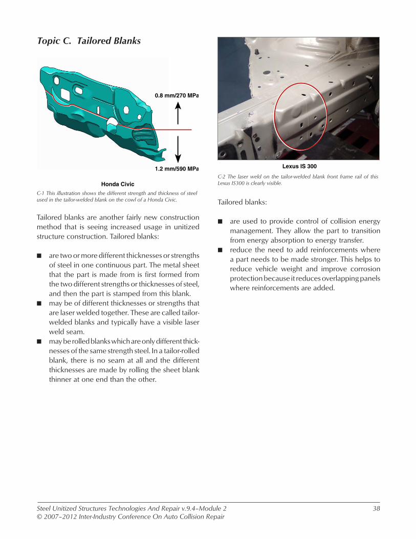
C-1 This illustration shows the different strength and thickness of steel used in the tailor-welded blank on the cowl of a Honda Civic.
Tailored blanks are another fairly new construction method that is seeing increased usage in unitized structure construction. Tailored blanks:
n are two or more different thicknesses or strengths of steel in one continuous part. The metal sheet that the part is made from is first formed from the two different strengths or thicknesses of steel, and then the part is stamped from this blank.
n may be of different thicknesses or strengths that are laser welded together. These are called tailor-welded blanks and typically have a visible laser weld seam.
n may be rolled blanks which are only different thick-nesses of the same strength steel. In a tailor-rolled blank, there is no seam at all and the different thicknesses are made by rolling the sheet blank thinner at one end than the other.
Lexus IS 300
C-2 The laser weld on the tailor-welded blank front frame rail of this Lexus IS300 is clearly visible.
Tailored blanks:
n are used to provide control of collision energy management. They allow the part to transition from energy absorption to energy transfer.
n reduce the need to add reinforcements where a part needs to be made stronger. This helps to reduce vehicle weight and improve corrosion protection because it reduces overlapping panels where reinforcements are added.
0.8 mm/270 MPa
1.2 mm/590 MPa
Honda Civic
Topic C. Tailored Blanks
Steel Unitized Structures Technologies And Repair v.9.4–Module 2© 2007–2012 Inter-Industry Conference On Auto Collision Repair
39
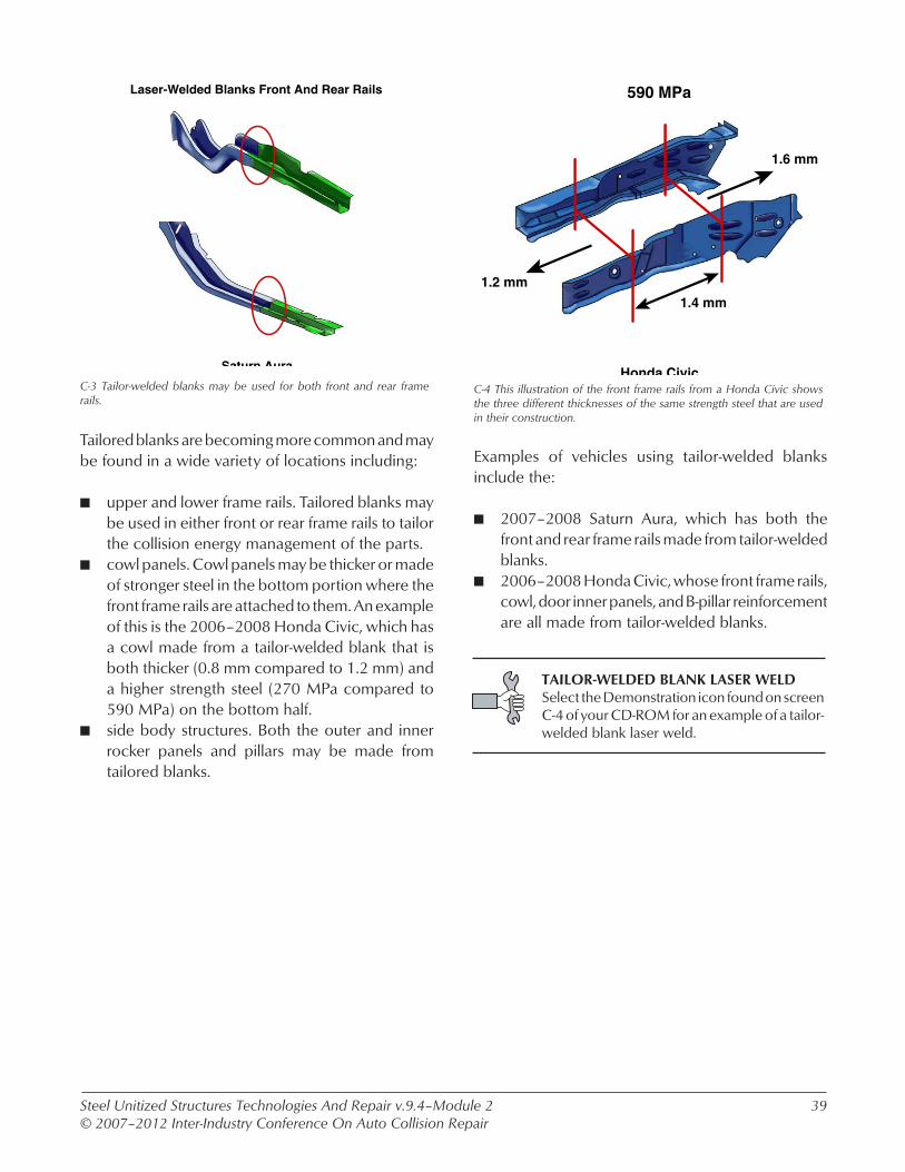
C-3 Tailor-welded blanks may be used for both front and rear frame rails.
Tailored blanks are becoming more common and may be found in a wide variety of locations including:
n upper and lower frame rails. Tailored blanks may be used in either front or rear frame rails to tailor the collision energy management of the parts.
n cowl panels. Cowl panels may be thicker or made of stronger steel in the bottom portion where the front frame rails are attached to them. An example of this is the 2006–2008 Honda Civic, which has a cowl made from a tailor-welded blank that is both thicker (0.8 mm compared to 1.2 mm) and a higher strength steel (270 MPa compared to 590 MPa) on the bottom half.
n side body structures. Both the outer and inner rocker panels and pillars may be made from tailored blanks.
C-4 This illustration of the front frame rails from a Honda Civic shows the three different thicknesses of the same strength steel that are used in their construction.
Examples of vehicles using tailor-welded blanks include the:
n 2007–2008 Saturn Aura, which has both the front and rear frame rails made from tailor-welded blanks.
n 2006–2008 Honda Civic, whose front frame rails, cowl, door inner panels, and B-pillar reinforcement are all made from tailor-welded blanks.
Laser-Welded Blanks Front And Rear Rails
Saturn Aura
590 MPa
1.2 mm
1.4 mm
Honda Civic
1.6 mm
TAILOR-WELDED BLANK LASER WELDSelect the Demonstration icon found on screen C-4 of your CD-ROM for an example of a tailor-welded blank laser weld.

Steel Unitized Structures Technologies And Repair v.9.4–Module 2© 2007–2012 Inter-Industry Conference On Auto Collision Repair
40
C-5 This illustration of the tailor-rolled B-pillar on a Dodge Caliber shows the different thickness of the part.
Examples of vehicles using tailor-rolled blanks include the:
n 2007–2008 Dodge Caliber. Tailor-rolled blanks are used in the B-pillar reinforcements.
n 2006–2008 Audi A3. Tailor-rolled blanks are used in the rocker panel reinforcements.
Lexus IS 300
1.85–1.05 mm
1.9 mm
1.65–1.85 mm
1.6 mm
1.75–1.65 mmTransition Zone
1.8 mm
1.0 mm Mild Steel
1.0 mm
Dodge Caliber C-6 A tailor-welded blank frame rail may deform in front of the laser weld and maintain its shape behind it.
Considerations with tailored blanks include:
n that parts may deform at the transition point between the two strengths or thicknesses of steel.
n collateral damage during straightening to the weaker or thinner portion of the part. If straighten-ing is being done to the thicker or stronger portion, carefully monitor the part for unwanted collateral damage during the straightening process.
n the laser weld is typically not a sectioning joint. Never section a tailor-welded blank at the laser weld unless called for in a vehicle maker proce-dure.
Steel Unitized Structures Technologies And Repair v.9.4–Module 2© 2007–2012 Inter-Industry Conference On Auto Collision Repair
41
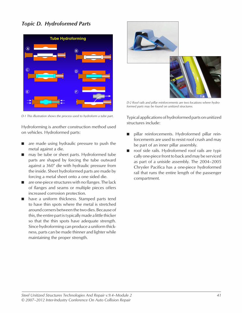
D-1 This illustration shows the process used to hydroform a tube part.
Hydroforming is another construction method used on vehicles. Hydroformed parts:
n are made using hydraulic pressure to push the metal against a die.
n may be tube or sheet parts. Hydroformed tube parts are shaped by forcing the tube outward against a 360° die with hydraulic pressure from the inside. Sheet hydroformed parts are made by forcing a metal sheet onto a one sided die.
n are one-piece structures with no flanges. The lack of flanges and seams or multiple pieces offers increased corrosion protection.
n have a uniform thickness. Stamped parts tend to have thin spots where the metal is stretched around corners between the two dies. Because of this, the entire part is typically made a little thicker so that the thin spots have adequate strength. Since hydroforming can produce a uniform thick-ness, parts can be made thinner and lighter while maintaining the proper strength.
D-2 Roof rails and pillar reinforcements are two locations where hydro-formed parts may be found on unitized structures.
Typical applications of hydroformed parts on unitized structures include:
n pillar reinforcements. Hydroformed pillar rein-forcements are used to resist roof crush and may be part of an inner pillar assembly.
n roof side rails. Hydroformed roof rails are typi-cally one-piece front to back and may be serviced as part of a uniside assembly. The 2004–2005 Chrysler Pacifica has a one-piece hydroformed rail that runs the entire length of the passenger compartment.
Tube Hydroforming
A
C
E
B
D
F
Topic D. Hydroformed Parts

Steel Unitized Structures Technologies And Repair v.9.4–Module 2© 2007–2012 Inter-Industry Conference On Auto Collision Repair
42
Volvo C70
D-3 The hydroformed A-pillar reinforcement on this Volvo C70 convert-ible would make straightening the pillar very difficult.
Considerations with hydroformed parts include:
n that they are difficult to straighten. Because of their closed tube design, straightening visible damage is very difficult. Leaving a buckle in the side of a tubular part will create a collapse zone at that point if exposed to forces from the right direction.
n part replacement issues. Hydroformed rails are often large parts that are behind multiple seams from adjacent assemblies. Replacing pillars or portions of unisides that have hydroformed reinforcements or rails may require sectioning of the hydroformed part. An example of this is the 2004–2005 Chrysler Pacifica uniside, which is supplied as a partial front or back assembly and contains a hydroformed roof rail reinforcement that requires sectioning when replacing either portion.
Volvo XC90
E-1 This B-pillar reinforcement is sandwiched very close to the outer panel.
Inner reinforcements:
n are used to add strength to a part. They are typi-cally placed where the part is intended to transi-tion from energy absorption to energy transfer.
n may be in multiple locations on the frame rails of modern vehicles. Inner reinforcements may be found spaced along the entire length of the rail and may be used to help design crush zones into the part.
n are typically made from HSS or UHSS.
Topic E. Multiple Layer Construction

Steel Unitized Structures Technologies And Repair v.9.4–Module 2© 2007–2012 Inter-Industry Conference On Auto Collision Repair
43
2005 Subaru ForesterE-3 This Subaru forester B-pillar has multiple layered reinforcements in order to create a very strong part.
Structural parts may have multiple reinforcements inside them. Reinforcements may:
n be staggered through the part to help create col-lapse zones. This is especially true of frame rails. The areas that are reinforced will be very strong and transfer collision energy while the areas between the reinforcements will be weaker and will collapse to absorb energy.
n be layered on top of each other in a part. This is done to add strength to the part and to keep it from collapsing. Layered reinforcements are typically found in A-, B-, and C-pillars.
n not be serviced as separate parts. Typically, rein-forcements are not serviced separately but are supplied with the part that they reinforce.
Volvo XC90
E-2 This rear frame rail has multiple staggered reinforcements located inside of it.
Considerations with inner reinforcements include:
n that they limit the amount of straightening that can be done. Areas that have HSS or UHSS reinforce-ments inside will be so stiff and strong that it is often not practical to straighten visible damage in these areas. Straightening of rails or pillars in reinforced areas is limited to minor movement of the part that does not show visible deforma-tion.
n limits to sectioning locations for the part. Heat input from welding is a consideration because inner reinforcements are typically made from higher strength steels. Reinforcements are typically not serviced as separate parts, but are included with, and spot welded to, the part that they are reinforcing. This can make it difficult to make a cut through the outer panel without cutting into the reinforcement.
n corrosion protection considerations because of limited access to parts that are buried deep within an assembly.

Steel Unitized Structures Technologies And Repair v.9.4–Module 2© 2007–2012 Inter-Industry Conference On Auto Collision Repair
44
Nylon ReinforcementsOn A Saturn Aura
E-4 This illustration shows the location of nylon reinforcement inserts used on the Saturn Aura.
Reinforcement inserts:
n may be made from nylon or aluminum.n must be replaced if damaged. They are designed
to absorb collision energy and then transfer it to a specific location once they have collapsed. If a reinforcement insert is damaged and not replaced, it will not perform this function in a subsequent collision.
n are typically adhesively bonded. When replac-ing an adhesively bonded reinforcement insert, thoroughly clean off any old or loose adhesive from the structure and use the recommended adhesive.
E-5 This cutaway shows how the roof and side structures can be layered over each other.
Repair considerations created by panel layering include:
n outer panels layered over inner panels. For example, a roof skin and rails may be layered over pillars and uniside assemblies, requiring roof removal to replace the entire uniside. Upper front frame rails may also be layered over the radiator core support.
n that the build sequence affects access to joints that require separation for the replacement of parts. The order that overlapping panels were put on at the factory may affect how parts are replaced during repairs. The outer layer may be larger or smaller than the underlying parts, causing joints to be covered by the next panel out.
n that sectioning of parts may be limited by multiple layers. As an example, a B-pillar that is made with five layers might require windows to be cut into three of the layers to section the entire B-pillar, thus making it impractical. In other instances, multiple layers may lead to the vehicle maker developing unique sectioning procedures to avoid removing undamaged parts during repairs. An example of this is the 2005–2007 Saturn Outlook B-pillar.

Steel Unitized Structures Technologies And Repair v.9.4–Module 2© 2007–2012 Inter-Industry Conference On Auto Collision Repair
45
2004 Subaru Outback B-Pillar
E-6 This multi-layered B-pillar, from a 2002 Subaru Legacy Outback, would be very difficult to straighten if bent.
Straightening considerations for parts that have mul-tiple layers include:
n limited access to the inside layers. If a multi-layer B-pillar is bent, the inside layers may be damaged as well as the outer layers. The damage may have been pushed from one panel to the next as the panels collapse against each other. Pulling and straightening the outside panel may not transfer the corrective forces to the inner panels, making them impossible to straighten without removing the outer panels.
n that damaged reinforcements may hold damage in the outer panels of an assembly. Reinforce-ments may be made from higher strength steel than the part they are inside of. Because of this, the straightening force that can be applied to the outer panels without damaging them is not great enough to move the damage to the inner reinforcement. There is also typically not enough access to the inside to properly stress relieve the damaged reinforcement.
E-7 This technician is stress relieving while pulling to help avoid collateral damage to the structure.
Additional straightening considerations include:
n collateral damage to other parts of the vehicle when pulling. A multi-layered pillar or uniside will typically be the strongest part of a vehicle. Because of this strength difference, pulling these assemblies with structural straightening equip-ment may break spot welds where the assembly is connected to weaker parts of the vehicle. Some outer unisides may also be considered non-struc-tural by the vehicle maker and be made of lower strength steel than the inner and reinforcements. This makes moving the inner panels by pulling on the outer panels difficult to do without further damaging the outer panel.
n that cutting windows to access inner panels and reinforcements is considered a sectioning procedure. There may be vehicle maker proce-dures for sectioning of outer side structures and trunk floors that can be used to aid in access for straightening.

Steel Unitized Structures Technologies And Repair v.9.4–Module 2© 2007–2012 Inter-Industry Conference On Auto Collision Repair
46
Chevrolet Cobalt
E-8 This prop shows the pre-sleeved service part that is used for section-ing the upper frame rails when replacing the radiator core support on a Chevrolet Cobalt.
The build sequence of a vehicle affects the repair process:
n because of overlapping panels. The build sequence of a front structure may cause the radia-tor core support to be on top of or underneath the upper frame rails. Overlapping panels are more common on vehicle side structures than front structures. The side structure may be overlapped on top of the roof skin, or the roof skin may be overlapped on top of the side structure.
n and may require undamaged part removal or sectioning of outer panels when replacing certain parts. When replacing a complete uniside that is layered underneath a roof skin, the roof skin may require replacement also. Because of build geometry and layering, upper frame rails may require removal to replace a radiator core sup-port that they are layered over. An example of this is the 2005–2007 Chevrolet Cobalt, which requires partial replacement of both outer upper rails when replacing the radiator core support.
LAYERED B-PILLAR REPLACEMENTRefer to screen E-9v of your CD-ROM for a video on replacing a layered B-pillar inner reinforcement assembly without removing the roof.
Buick LaCrosse
F-1 NVH foam is used where the upper frame rail connects to the A-pillar to block the movement of air through the parts.
NVH foam:
n is used in vehicles to control noise and vibration and to block air movement that may cause drafts or wind noise.
n may fill sections of pillars and rocker panels. Rocker panels can be completely filled with foam or they may have small sections filled. Pillars are typically filled towards the bottom or in small sections along their length to block air movement through door hinge fasteners.
n may be flexible or rigid, but is typically a low density product in either case.
Topic F. Foams
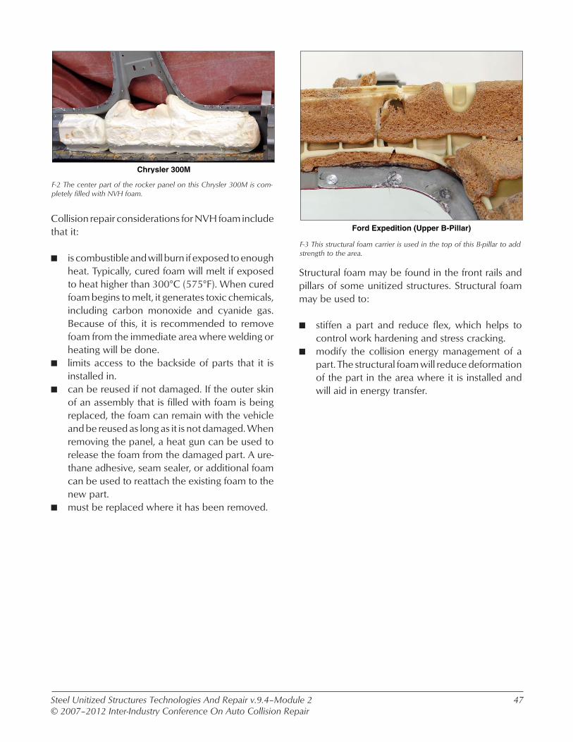
Steel Unitized Structures Technologies And Repair v.9.4–Module 2© 2007–2012 Inter-Industry Conference On Auto Collision Repair
47
Chrysler 300M
F-2 The center part of the rocker panel on this Chrysler 300M is com-pletely filled with NVH foam.
Collision repair considerations for NVH foam include that it:
n is combustible and will burn if exposed to enough heat. Typically, cured foam will melt if exposed to heat higher than 300°C (575°F). When cured foam begins to melt, it generates toxic chemicals, including carbon monoxide and cyanide gas. Because of this, it is recommended to remove foam from the immediate area where welding or heating will be done.
n limits access to the backside of parts that it is installed in.
n can be reused if not damaged. If the outer skin of an assembly that is filled with foam is being replaced, the foam can remain with the vehicle and be reused as long as it is not damaged. When removing the panel, a heat gun can be used to release the foam from the damaged part. A ure-thane adhesive, seam sealer, or additional foam can be used to reattach the existing foam to the new part.
n must be replaced where it has been removed.
Ford Expedition (Upper B-Pillar)
F-3 This structural foam carrier is used in the top of this B-pillar to add strength to the area.
Structural foam may be found in the front rails and pillars of some unitized structures. Structural foam may be used to:
n stiffen a part and reduce flex, which helps to control work hardening and stress cracking.
n modify the collision energy management of a part. The structural foam will reduce deformation of the part in the area where it is installed and will aid in energy transfer.

Steel Unitized Structures Technologies And Repair v.9.4–Module 2© 2007–2012 Inter-Industry Conference On Auto Collision Repair
48
Cadillac DTS
F-4 The rear portion of the service front frame rail for a Cadillac DTS is filled with structural foam.
Collision repair considerations for structural foam include:
n the fact that it may be supplied pre-installed in the service part for some frame rails.
n if it is broken loose and rattling that vehicle maker recommendations for repair may differ. This may require replacement of the frame rail on some vehicles while for others the loose foam may be reattached by full filling the area with additional structural foam. Check vehicle maker service information for the proper procedure for the application.
Ford says to reattach loose structural foam by full filling with additional foam. Loose structural foam in the frame rail of a Cadillac DTS requires frame rail replacement due to limited access.
NVH AND STRUCTURAL FOAM SAMPLESSelect the Demonstration icon found on screen F-4 of your CD-ROM for examples of NVH and structural foam.
Kent Ure-Foam does not list a flash point for non-cured part A. Part B has a non-cured flash point of 254°C (490°F). According to the MSDS, if this material catches fire, the
recommend fire fighting materials include carbon dioxide, dry chemical, foam, alcohol foam, or water fog. According to the MSDS, special fog nozzles are recommended if water is to be used for extinguish-ing a fire.
Fusor 1908 structural foam and Motorcraft® structural foam, have a flash point of the non-cured material of 93°C (201°F) for non-cured material. According to the MSDS, if this material catches fire, the recom-mended fire fighting materials include carbon dioxide, dry chemical, foam, or water fog. According to the MSDS, special fog nozzles are recommended if water is to be used for extinguishing a fire.

Steel Unitized Structures Technologies And Repair v.9.4–Module 2© 2007–2012 Inter-Industry Conference On Auto Collision Repair
49
G-2 This Chrysler publication gives recommendations for welding and weld bonding on their vehicles.
Considerations for weld bonded side structures include:
n vehicle maker recommendations for part replace-ment. Recommendations vary from vehicle maker to vehicle maker with some recommending weld bonding for repair and others recommending increasing the number of spot welds used and leaving the adhesive out. Follow the recommenda-tion for the vehicle being repaired when factory weld bonding is present.
n that part removal may be aided by using heat to loosen the adhesive. Also remember that adhe-sives have poor peel strength so using a chisel to peel apart the flange works better than trying to pull the part straight off.
Topic G. Weld Bonding
Chrysler 300M
G-1 This outer rocker panel is being installed using weld bonding.
Weld bonding:
n is a combination of resistance spot welds and structural adhesive for attaching parts. Weld bonding is being used more and more on vehicle structures as the finished joint is stronger than a joint that is only spot welded. The adhesive also adds additional benefits such as NVH control and corrosion protection to the joint.
n can typically be found on the vehicle side struc-ture.
WELD BONDINGRefer to screen G-3v of your CD-ROM for a video on weld bonding.

Steel Unitized Structures Technologies And Repair v.9.4–Module 2© 2007–2012 Inter-Industry Conference On Auto Collision Repair
50
H-2 This pulse MIG welding machine has pre-programmed parameters for MIG brazing.
MIG brazing:
n is done using GMA (MIG) welding equipment. Because the electrode wire is softer than steel wire, plastic cable liners and half-round smooth drive rolls are typically used. Pulse MIG equip-ment yields the best results as it provides the lowest heat input into the metal and produces almost spatter free welds. Some machines may have pre-programmed parameters for MIG braz-ing.
n uses copper-silicon (CuSi3) or bronze alloy (CuAi8) electrode wire. Copper-silicon is the most common electrode wire for MIG brazing sheet steel.
n typically uses 100% argon for the shielding gas. Shielding gas flow rates are typically set in the 25–30 cfh range.
Topic H. MIG Brazing
GMA (MIG) Welding
MIG Brazing
H-1 This illustration shows the difference between the fusion GMA (MIG) welding process and the non-fusion MIG brazing process.
MIG brazing:
n is a non-fusion joining process. Factory MIG brazed joints are found on some cosmetic exte-rior panel joints such as the quarter panel to roof seam, and may also be found in limited areas of the vehicle structure.
n uses much lower heat than GMA (MIG) welding and therefore, damages much less of the factory zinc coating. The reduced heat input will also create a much narrower heat affect zone, result-ing in less damage to the strength of the steel being joined.

Steel Unitized Structures Technologies And Repair v.9.4–Module 2© 2007–2012 Inter-Industry Conference On Auto Collision Repair
51
Land Rover Ranger Rover Sport
H-3 This illustration shows the location of the MIG braze slot welds made when replacing the outer A-pillar on the Land Rover Range Rover Sport.
MIG brazing for collision repairs is fairly new, vehicle maker recommendations vary including:
n no mention of the process.n duplicating factory MIG brazed joints during the
repair process. Toyota has numerous references in their collision repair manuals to brazing roof panel-to pillar joints and quarter panel to rear body panel at the drip channel joint.
n replacing factory GMA (MIG) welds with MIG brazing. Currently, most of the recommendations for using MIG brazing on structural parts apply to European vehicles that are not available in North America, including the Vauxhall Vectra C Opel, the Volkswagen Golf, and the PSA Peugeot Citroen1s. One North American Example is the outer A-pillar to UHSS inner panel joint on the 2006 Land Rover Range Rover Sport. MIG braze slot welds are made through the replacement A-pillar to the UHSS inner panel.
MIG BRAZING SAMPLESelect the Demonstration icon found on screen H-3 of your CD-ROM for an example of MIG brazing.
Topic I. Summary
Volvo S40
Mild SteelHigh-Strength SteelExtra-High-Strength SteelUltra-High-Strength Steel
I-1 This illustration shows the steel types used on the Volvo S40 body shell.
Vehicle design and construction processes are:
n changing rapidly with passenger safety at the forefront of many. Vehicles are being designed and built different from what we have become used to working on.
n using many new steels that were not in vehicles of just a few years ago.
n using new build geometries to help control and transfer collision energy around the passenger compartment of the vehicle.
n using new construction methods to attach parts. The increased use of HSS and UHSS, as well as the desire for increased NVH and corrosion control, has led to the vehicle makers adopting new construction methods for the attachment of some parts.

Steel Unitized Structures Technologies And Repair v.9.4–Module 2© 2007–2012 Inter-Industry Conference On Auto Collision Repair
52
Buick Enclave
I-2 The ultra-high-strength steel inner reinforcements are being slid up into a portion of the inner B-pillar assembly that remains on this Buick Encalve when replacing the B-pillar.
The way vehicles are built is changing and it is impact-ing the repair process. Collision repairs:
n are changing along with the way vehicles are built. The vehicle makers’ emphasis on comfort and safety has to become a part of the thinking we use during repairs also.
n on new vehicles may use new techniques and procedures that weren’t part of the process just a few years ago.
n may require new skills and equipment that didn’t exist a few years ago.
n are being supported by the vehicle makers at a greater level that ever before. Vehicle maker part replacement and sectioning procedures are becoming more common on the newer design vehicles.
I-3 New steels and construction techniques are leading to less structural straightening and more complete part replacement.
Because of the new higher strength steels and designs being used in vehicles, collision repairs are involving:
n less structural straightening. With parts being made from steels 2–3 times stronger than in the past, and with reinforcements and multiple layer-ing of panels, straightening of structural parts is becoming more difficult.
n more structural part replacement. Since parts are more difficult to straighten, more parts are being replaced. Structural parts can be sectioned where there is a procedure, but may have to be replaced in their entirety because of design or vehicle maker recommendations.