Embed Size (px)
Citation preview

Form No. 3374-188 Rev A
Power Max 724 OE SnowthrowerModel No. 37770—Serial No. 313000001 and Up
Operator's Manual
IntroductionThis machine is intended to be used by residentialhomeowners or professional, hired operators. It isdesigned for removing snow from paved surfaces, suchas driveways and sidewalks, and other surfaces fortraffic on residential or commercial properties. It is notdesigned for removing materials other than snow, nor isa model with a pivoting scraper designed for clearing offgravel surfaces.
Read this information carefully to learn how to operate andmaintain your machine properly and to avoid injury andmachine damage. You are responsible for operating themachine properly and safely.
You may contact Toro directly at www.Toro.com for machineand accessory information, help finding a dealer, or to registeryour machine.
Whenever you need service, genuine Toro parts, or additionalinformation, contact an Authorized Service Dealer or ToroCustomer Service and have the model and serial numbers ofyour machine ready. Figure 1 identifies the location of themodel and serial numbers on the machine. Write the numbersin the space provided.
g018884
Figure 1
1. Model and serial number location
Model No.
Serial No.
This manual identifies potential hazards and has safetymessages identified by the safety alert symbol (Figure 2),
which signals a hazard that may cause serious injury or deathif you do not follow the recommended precautions.
Figure 2
1. Safety alert symbol
This manual uses 2 words to highlight information.Important calls attention to special mechanical informationand Note emphasizes general information worthy of specialattention.
WARNINGCALIFORNIA
Proposition 65 WarningThe engine exhaust from this productcontains chemicals known to the State ofCalifornia to cause cancer, birth defects,
or other reproductive harm.
This spark ignition system complies with Canadian ICES-002.
The enclosed Engine Owner's Manual is supplied forinformation regarding the US Environmental ProtectionAgency (EPA) and the California Emission ControlRegulation of emission systems, maintenance, andwarranty. Replacements may be ordered through theengine manufacturer.
ContentsIntroduction .................................................................. 1
Training ................................................................. 2Preparation............................................................. 3Operation............................................................... 3Clearing a CloggedDischarge Chute .......................... 4Maintenance and Storage.......................................... 4Toro Snowthrower Safety ......................................... 4Safety and Instructional Decals ................................. 5
Setup ............................................................................ 71 Installing the Upper Handle.................................... 82 Installing the Traction Control Linkage .................... 83 Installing the Chute ............................................... 94 Installing the Chute Control Rod ............................10
© 2012—The Toro® Company8111 Lyndale Avenue SouthBloomington, MN 55420
Register at www.Toro.com. Original Instructions (EN)Printed in the USAAll Rights Reserved *3374-188* A

5 Filling the Engine with Oil.....................................116 Checking the Tire Pressure ....................................117 Checking the Skids and Scraper ..............................118 Checking the TractionDriveOperation ...................12
Product Overview .........................................................13Operation ....................................................................13
Freewheeling or Using the Self-propel Drive...............13Filling the Fuel Tank ...............................................14Starting the Engine .................................................15Stopping the Engine ...............................................16Operating the Traction Drive ...................................16Operating the Speed Selector ...................................17Operating the Auger/Impeller Drive.........................17Operating the Quick Lever ......................................18Unclogging the Discharge Chute ..............................18Preventing Freeze-up ..............................................18Operating Tips ......................................................19
Maintenance .................................................................20
RecommendedMaintenance Schedule(s) ......................20Preparing for Maintenance.......................................20Checking the Engine Oil Level .................................20Checking and Adjusting the Skids andScraper ..............................................................21
Checking andAdjusting the Traction Cable ................21Checking and Adjusting the Auger/ImpellerCable ................................................................22
Checking the Auger GearboxOil Level ......................23Changing the Engine Oil .........................................23Lubricating the Hex Shaft ........................................24Replacing the Spark Plug .........................................24Adjusting the Discharge Chute Latch ........................25Replacing the Drive Belts.........................................25
Storage ........................................................................26Preparing theMachine for Storage ............................26Removing theMachine from Storage.........................26
Troubleshooting ...........................................................27
SafetyBefore Operating?
?
Read and understand the contents of thismanual before operating the snowthrower .Become familiar with all controls and knowhow to stop the engine quickly .
Operator 'sPosition
The low-speed auger has a moving pinchpoint close to the opening.
Caution: Improper use may result inloss of fingers, hands, or feet.
There is a high-speedimpeller close to theopening.
This machine meets or exceeds the B71.3 specificationsof the American National Standards Institute in effectat the time of production.
Read and understand the contents of this manual beforethe engine is ever started.
This is the safety alert symbol. It is used to alert youto potential personal injury hazards. Obey all safetymessages that follow this symbol to avoid possible injuryor death.
Improperly using or maintaining this machine couldresult in injury or death. To reduce this potential,comply with the following safety instructions.
Training• Read, understand and follow all instructions on the
machine and in the manual(s) before operating thismachine. Be thoroughly familiar with the controls and
2

the proper use of the machine. Know how to stop themachine and disengage the controls quickly.
• Never allow children to operate the machine. Never allowadults to operate the machine without proper instruction.
• Keep the area of operation clear of all persons, particularlysmall children.
• Exercise caution to avoid slipping or falling, especiallywhen operating the machine in reverse.
Preparation• Thoroughly inspect the area where the machine is to be
used and remove all doormats, sleds, boards, wires, andother foreign objects.
• Disengage all clutches and shift into neutral beforestarting the engine.
• Do not operate the machine without wearing adequatewinter garments. Avoid loose fitting clothing that can getcaught in moving parts. Wear footwear that will improvefooting on slippery surfaces.
• Handle fuel with care; it is highly flammable.
– Use an approved fuel container.
– Never add fuel to a running engine or hot engine.
– Fill fuel tank outdoors with extreme care. Never fillfuel tank indoors.
– Never fill containers inside a vehicle or on a truck ortrailer bed with a plastic liner. Always place containerson the ground, away from your vehicle, before filling.
– When practical, remove gas-powered machinery fromthe truck or trailer and refuel it on the ground. Ifthis is not possible, then refuel such machinery on atrailer with a portable container, rather than from agasoline dispenser nozzle.
– Keep the nozzle in contact with the rim of the fueltank or container opening at all times, until refuelingis complete. Do not use a nozzle lock-open device.
– Replace gasoline cap securely and wipe up spilled fuel.
– If fuel is spilled on clothing, change clothingimmediately.
• Use extension cords and receptacles as specified bythe manufacturer for all machines with electric startingmotors.
• Adjust the collector housing to clear gravel or crushedrock surface.
• Never attempt to make any adjustments while the engineis running (except when specifically recommended bymanufacturer).
• Always wear safety glasses or eye shields during operationor while performing an adjustment or repair to protecteyes from foreign objects that may be thrown from themachine.
Operation• Do not put hands or feet near or under rotating parts.
Keep clear of the discharge opening at all times.
• Exercise extreme caution when operating on or crossinggravel drives, walks, or roads. Stay alert for hiddenhazards or traffic.
• After striking a foreign object, stop the engine, removethe ignition key, thoroughly inspect the machine for anydamage, and repair the damage before restarting andoperating the machine.
• If the machine should start to vibrate abnormally, stop theengine and check immediately for the cause. Vibration isgenerally a warning of trouble.
• Stop the engine whenever you leave the operatingposition, before unclogging the auger/impeller housingor discharge chute, and when making any repairs,adjustments or inspections.
• When cleaning, repairing or inspecting the machine, stopthe engine and make certain the auger/impeller and allmoving parts have stopped. Disconnect the spark plugwire and keep the wire away from the plug to preventsomeone from accidentally starting the engine.
• Do not run the engine indoors, except when startingthe engine and for transporting the machine in or outof the building. Open the outside doors; exhaust fumesare dangerous.
• Exercise extreme caution when operating on slopes.
• Never operate the machine without proper guards, andother safety protective devices in place and working.
• Never direct the discharge toward people or areas whereproperty damage can occur. Keep children and othersaway.
• Do not overload the machine capacity by attempting toclear snow at too fast a rate.
• Never operate the machine at high transport speedson slippery surfaces. Look behind and use care whenoperating in reverse.
• Disengage power to the auger/impeller when machine istransported or not in use.
• Use only attachments and accessories approved by themanufacturer of the machine (such as wheel weights,counterweights, or cabs).
• Never operate the machine without good visibility orlight. Always be sure of your footing, and keep a firmhold on the handles. Walk; never run.
• Never touch a hot engine or muffler.
3
Clearing a Clogged DischargeChute
WARNINGHand contact with the rotating rotor blades insidethe discharge chute is the most common cause ofinjury associated with machines. Never use yourhand to clean out the discharge chute.
To clear the chute:
• Shut the engine off !
• Wait 10 seconds to be sure the rotor blades have stoppedrotating.
• Always use the cleanout tool mounted on thesnowthrower, not your hands.
Maintenance and Storage• Check all fasteners at frequent intervals for proper
tightness to be sure the machine is in safe workingcondition.
• Never store the machine with fuel in the fuel tank inside abuilding where ignition sources are present such as hotwater heaters, space heaters, or clothes dryers. Allow theengine to cool before storing in any enclosure.
• Always refer to the Operator’s Manual for important detailsif the machine is to be stored for an extended period.
• Maintain or replace safety and instruction labels, asnecessary.
• Run the machine a few minutes after throwing snow toprevent freeze-up of the rotor blades.
Toro Snowthrower SafetyThe following list contains safety information specific to Toromachines or other safety information that you must know.
• Rotating auger/impeller can cut off or injure fingersor hands. Stay behind the handles and away from thedischarge opening while operating the machine. Keepyour face, hands, feet, and any other part of yourbody or clothing away from moving or rotating parts.
• Before adjusting, cleaning, inspecting, troubleshooting, orrepairing the machine, stop the engine, remove the key,and wait for all moving parts to stop. Disconnectthe wire from the spark plug and keep it away fromthe spark plug to prevent someone from accidentallystarting the engine.
• Before leaving the operating position, stop the engine,remove the key, and wait for all moving parts to stop.
• To unclog the discharge chute, stay in the operatingposition and release the left hand (traction) lever. Whilerunning the auger/impeller, push down on the handles to
raise the front of the machine a few inches (centimeters)off the pavement. Then lift the handles quickly to bumpthe front of the machine on the pavement. Repeat ifnecessary until a stream of snow comes out the dischargechute.
• If you cannot unclog the discharge chute by bumpingthe front of the machine, stop the engine, wait forall moving parts to stop, and use the cleanout tool;never use your hand.
• If a shield, safety device, or decal is damaged, illegible, orlost, repair or replace it before beginning operation.
• Do not smoke while handling gasoline.
• Do not use the machine on a roof.
• Do not touch the engine while it is running or soon afterit has stopped because the engine may be hot enough tocause a burn.
• Perform only those maintenance instructions described inthis manual. Before performing any maintenance, service,or adjustment, stop the engine, remove the key, anddisconnect the wire from the spark plug. If major repairsare ever needed, contact your Authorized Service Dealer.
• Do not change the governor settings on the engine.
• When storing the machine for more than 30 days, drainthe fuel from the fuel tank to prevent a potential hazard.Store fuel in an approved fuel container. Remove the keyfrom the ignition switch before storing the machine.
• Purchase only genuine Toro replacement parts andaccessories.
4

Safety and InstructionalDecalsImportant: Safety and instruction decals are locatednear areas of potential danger. Replace damaged decals.
121–6823
1. Fast 3. Slow2. Forward speeds 4. Reverse speeds
121–6817
1. Cutting dismemberment, impeller and cuttingdismemberment, auger hazards—keep bystanders a safedistance from the snowthrower.
121–1239Reorder part no. 119–7629
121–1240Reorder part no. 120–7194
1. Traction drive—squeeze the lever to engage; release thelever to disengage.
4. Cutting dismemberment hazard, impeller—keep awayfrom moving parts; remove the ignition key and read theinstructions before servicing or performing maintenance.
2. Warning—read the Operator’s Manual. 5. Thrown object hazard—keep bystanders a safe distance fromthe snowthrower.
3. Cutting/dismemberment hazard, impeller—do not placeyour hand in the chute; stop the engine before leaving theoperating position, use the tool to clear the chute.
6. Auger/impeller drive—squeeze the lever to engage; releasethe lever to disengage.
5

Briggs & Stratton Part No. 273676
1. Stop 3. Fast2. Slow
Briggs & Stratton Part No. 275949
1. Choke on (Choke) 2. Choke off (Run)
Briggs & Stratton Part No. 276925
1. Warning—read theOperator's Manual.
3. Warning—toxic gasinhalation hazard.
2. Warning—fire hazard. 4. Warning—hotsurface/burn hazard.
Briggs & Stratton Part No. 277566
1. When starting a coldengine, close the chokeand press the primer twotimes.
2. When starting a warmengine, open the chokeand do not press theprimer.
Briggs & Stratton Part No. 277588
1. Primer 3. Ignition key out(Engine—Stop)
2. Ignition key in(Engine—Run)
Briggs & Stratton Part No. 278866
1. Fuel—On 2. Fuel—Off
6

SetupLoose PartsUse the chart below to verify that all parts have been shipped.
Procedure Description Qty. UseHandle bolts 2Curved washers 21Locknuts 2
Install the upper handle.
2 No parts required – Install the traction control linkage.
Nut 23 Bolt 2 Install the chute.
Carriage bolts 24 Locknuts 2 Install the chute control rod.
5 No parts required – Fill the engine with oil.
6 No parts required – Check the tire pressure.
7 No parts required – Check the skids and scraper.
8 No parts required – Check the operation of the traction drive.
7

1Installing the Upper Handle
Parts needed for this procedure:2 Handle bolts
2 Curved washers
2 Locknuts
Procedure1. Lift and rotate the upper handle and position it over
the lower handle (Figure 3).
2. Install 2 handle bolts, 2 curved washers, and 2 locknutsin the lower handle holes (Figure 3).
g019003
Figure 3
2Installing the Traction ControlLinkageNo Parts Required
Procedure1. Remove the hairpin cotter and washer from the lower
end of the speed control rod and insert the lower endof the rod into the lower link arm so that the bent endof the speed control rod faces rearward (Figure 4).
g019004
Figure 4
2. Secure the lower end of the speed control rod with thewasher and hairpin cotter that you previously removed.
3. Remove the hairpin cotter and the outer washer fromthe trunnion on the upper end of the speed controlrod (Figure 5).
Figure 5
1. Speed selector lever 3. Inner washer2. Trunnion 4. Outer washer
Note: To make installation easier, leave the flat washeron the trunnion (Figure 5).
4. Shift the speed selector lever into Position F6.
8

5. Rotate the lower link arm fully downward (clockwise)(Figure 6).
Figure 6
6. Push down on the speed control rod and insert thetrunnion into the hole in the speed selector lever(Figure 5).
Note: If the trunnion does not fit into the holewhen you lift up on the speed control rod, rotate thetrunnion upward or downward on the speed controlrod until it fits.
7. Secure the trunnion and upper end of the speed controlrod with the outer washer and a hairpin cotter youpreviously removed.
Note: For easier installation, look down through theopening in the speed selector (Figure 7).
Figure 7
1. Speed selector
3Installing the Chute
Parts needed for this procedure:2 Nut
2 Bolt
Procedure1. Place the chute on the frame and the align the discharge
chute mount to the chute support.
g019013
1 2
Figure 8
1. Bolt 2. Nut
2. Secure the discharge chute mount using 2 bolts and2 nuts.
9

4Installing the Chute ControlRodParts needed for this procedure:
2 Carriage bolts
2 Locknuts
Procedure1. Remove the blue rod cap from the chute control rod.
2. Insert the front end of the rod into the opening inthe back of the chute gear cover until it slides into thechute gear (Figure 10).
g019005
Figure 9
1. Short rod 2. Long chute control rod
g018899
Figure 10
3. Align the holes in the nested ends of the rods andinsert 2 carriage bolts (in the loose parts bag) through
the short rod from the left side of the machine (fromthe operating position).
4. Ensure the chute control operates smoothly.
10
5Filling the Engine with Oil
No Parts Required
ProcedureYour machine comes with oil in the engine crankcase.
Note: Before starting the engine, check the oil level andadd oil if necessary.
Use automotive detergent oil with an API service classificationof SF, SG, SH, SJ, SL, or higher. Refer to your engine owner'smanual.
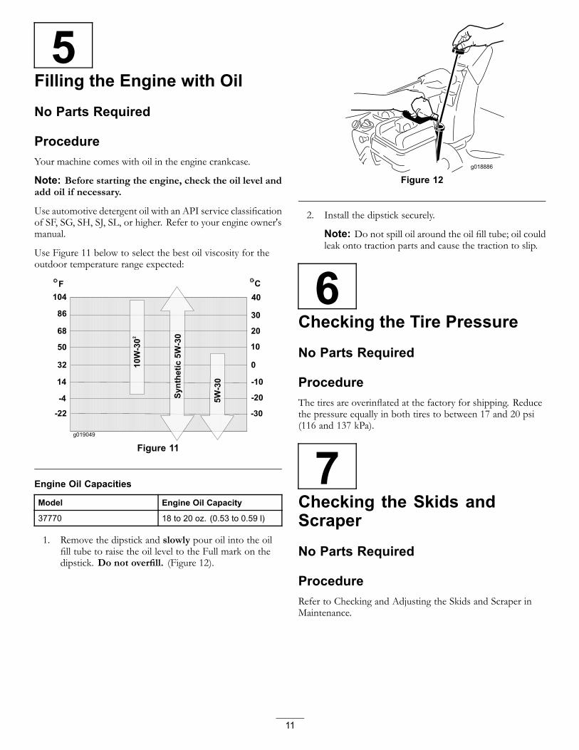
Use Figure 11 below to select the best oil viscosity for theoutdoor temperature range expected:
g019049
Figure 11
Engine Oil Capacities
Model Engine Oil Capacity
37770 18 to 20 oz. (0.53 to 0.59 l)
1. Remove the dipstick and slowly pour oil into the oilfill tube to raise the oil level to the Full mark on thedipstick. Do not overfill. (Figure 12).
g018886
Figure 12
2. Install the dipstick securely.
Note: Do not spill oil around the oil fill tube; oil couldleak onto traction parts and cause the traction to slip.
6Checking the Tire Pressure
No Parts Required
ProcedureThe tires are overinflated at the factory for shipping. Reducethe pressure equally in both tires to between 17 and 20 psi(116 and 137 kPa).
7Checking the Skids andScraper
No Parts Required
ProcedureRefer to Checking and Adjusting the Skids and Scraper inMaintenance.
11

8Checking the Traction DriveOperation
No Parts Required
Procedure
CAUTIONIf the traction drive is not properly adjusted, themachine may move in the direction opposite ofwhat you intended, causing injury and/or propertydamage.
Carefully check the traction drive and adjust itproperly, if necessary.
Note: To check the traction drive operation,the self-propel feature must be engaged byensuring the wheels are pinned in the axle. Refer toFreewheeling or Using the Self-propel Drive (page 13).
1. Start the engine; refer to Starting the Engine.
2. Move the speed selector to Position R1; refer toOperating the Speed Selector.
3. Squeeze the left hand (traction) lever to the hand-grip(Figure 13).
Figure 13
The machine should move rearward. If the machinedoes not move or moves forward, complete thefollowing:
A. Release the traction lever and stop the engine.
B. Disconnect the trunnion from the speed selectorlever (Figure 5).
C. Turn the trunnion downward (clockwise) on thespeed control rod (Figure 5).
D. Connect the trunnion to the speed selector lever(Figure 5).
4. Release the traction lever.
5. Move the speed selector to the Position 1; refer toOperating the Speed Selector.
6. Squeeze the left hand (traction) lever to the hand-grip(Figure 13).
The machine should move forward. If the machinedoes not move or moves rearward, complete thefollowing:
A. Release the traction lever and stop the engine.
B. Disconnect the trunnion from the speed selectorlever (Figure 5).
C. Turn the trunnion upward (counterclockwise) onthe speed control rod (Figure 5).
D. Connect the trunnion to the speed selector lever(Figure 5).
7. If you made any adjustments, repeat this procedureuntil no adjustments are required.
Important: If the machine moves when the tractionlever is in the released position, check the traction cable(refer to Checking and Adjusting the Traction Cable) ortake the machine to an Authorized Service Dealer forservice.
12

Product Overview
g018896
Figure 14
1. Hand-grip (2) 9. Chute deflector2. Auger/impeller lever 10. Discharge chute3. Speed selector lever 11. Scraper4. Quick lever discharge
chute control12. Auger
5. Traction lever 13. Skid (2)6. Fuel tank cap 14. Electric starter button7. Engine oil fill tube/dipstick 15. Electric starter plug-in8. Chute deflector trigger 16. Snow cleanout tool
g018888
Figure 15
1. Choke 5. Recoil starter2. Ignition switch 6. Oil drain plug3. Fuel shutoff valve 7. Primer4. Throttle
Figure 16
1. Snow cleanout tool (attached to the handle)
OperationNote: Determine the left and right sides of the machinefrom the normal operating position.
Freewheeling or Using theSelf-propel DriveYou can operate the snowthrower with the self-propel featureengaged or disengaged (freewheeling).
To freewheel, insert the axle pins through the axle holes, butnot through the wheel hubs (Figure 17).
g019015
Figure 17
To self-propel, insert the axle pins through the holes in thewheel hubs and the axle holes (Figure 18).
g019014
Figure 18
13
Filling the Fuel TankDANGER
Gasoline is extremely flammable and explosive. Afire or explosion from gasoline can burn you andothers.
• To prevent a static charge from igniting thegasoline, place the container and/or machineon the ground before filling, not in a vehicle oron an object.
• Fill the tank outdoors when the engine is cold.Wipe up spills.
• Do not handle gasoline when smoking or aroundan open flame or sparks.
• Store gasoline in an approved fuel container, outof the reach of children.
• For best results, use only clean, fresh, unleaded gasolinewith an octane rating of 87 or higher ((R+M)/2 ratingmethod).
• Oxygenated fuel with up to 10% ethanol or 15% MTBEby volume is acceptable.
• Do Not use ethanol blends of gasoline (such as E15or E85) with more than 10% ethanol by volume.Performance problems and/or engine damage may resultwhich may not be covered under warranty.
• Do Not use gasoline containing methanol.
• DoNot store fuel either in the fuel tank or fuel containersover the winter unless a fuel stabilizer is used.
• Do Not add oil to gasoline.
Important: To reduce starting problems, add fuelstabilizer to the fuel all season, mixing it with gasolineless than 30 days old. Do not add oil to the gasoline.
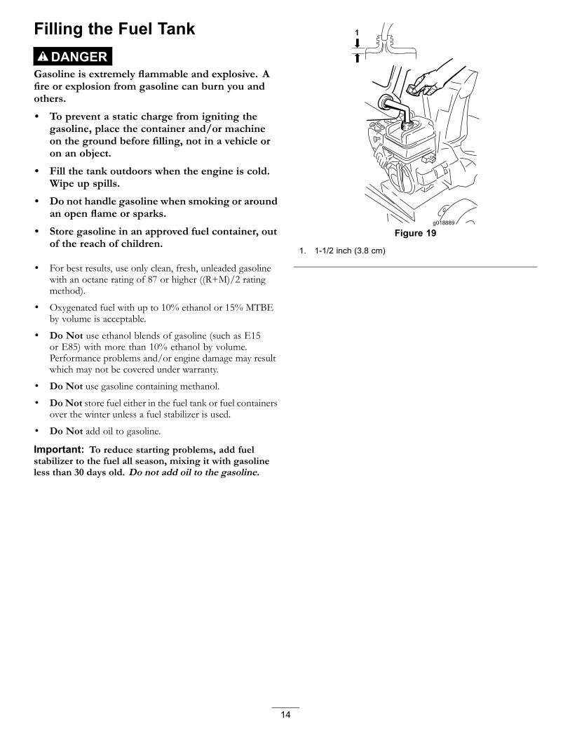
g018889
Figure 19
1. 1-1/2 inch (3.8 cm)
14

Starting the Engine1. Check the engine oil level. Refer to Checking the
Engine Oil Level in Maintenance.
2. Turn the fuel shutoff valve 1/4 turn counterclockwiseto open it (Figure 20).
Figure 20
3. Insert the ignition key (Figure 21).
g018890
Figure 21
1. Ignition key
4. Firmly push in the primer with your thumb 2 times(15°F or -9°C or above) or 4 times (below 15°F or-9°C), holding the primer in for a second beforereleasing it each time (Figure 22).
g018891
Figure 22
5. Rotate the choke to the Choke position (Figure 23).
g018892
Figure 23
6. Move the throttle to the Fast position (Figure 24).
Figure 24
7. Start the machine pulling the recoil starter or pressingthe electric-starter button (Figure 25).
15

g018893
Figure 25
1. Electric-starter button 3. Recoil starter2. Electric starter plug-in
Note: To use the electric starter, connect a powercord to the electric starter plug-in first and then to apower outlet. Use only a UL-listed, 16-gauge extensioncord recommended for outdoor use that is not longerthan 50 feet (15 m).
WARNINGThe electrical cord can become damaged,causing a shock or fire.
Thoroughly inspect the electrical cord beforeusing the machine. If the cord is damaged,do not operate the machine. Replace or repairthe damaged cord immediately. Contact anAuthorized Service Dealer for assistance.
Important: To prevent damaging the electricstarter, run it in short cycles (5 seconds maximum,then wait one minute before trying to start itagain). If the engine still does not start, takethe machine to an Authorized Service Dealer forservice.
8. Disconnect the power cord from the power outlet firstand then from the machine (electric start only).
9. Allow the engine to warm up for several minutes, movethe choke toward the Run position. Wait for the engineto run smoothly before each choke adjustment.
CAUTIONIf you leave the machine plugged into apower outlet, someone can inadvertently startthe machine and injure people or damageproperty.
Unplug the power cord whenever you are notstarting the machine.
Stopping the Engine1. Move the throttle to the Slow position, and then to the
Stop position (Figure 26).
Figure 26
2. Wait for all moving parts to stop before leaving theoperating position.
3. Remove the ignition key.4. Close the fuel shutoff valve by rotating it clockwise
(Figure 27).
Figure 27
5. Pull the recoil starter 3 or 4 times. This helps preventthe recoil starter from freezing up.
Operating the Traction DriveCAUTION
If the traction drive is not properly adjusted, themachine may move in the direction opposite ofwhat you intended, causing injury and/or propertydamage.
Carefully check the traction drive and adjust itproperly, if necessary; refer to Checking the TractionDrive Operation in Setup for more information.
Important: If the machine moves when the tractionlever is in the released position, check the traction cable(refer to Checking and Adjusting the Traction Cable) or
16
take the machine to an Authorized Service Dealer forservice.
Important: To operate the traction drive, you mustoperate the machine with the self-propel featureengaged. Refer to Freewheeling or Using the Self-propelDrive.
1. To engage the traction drive, squeeze the left hand(traction) lever to the handgrip (Figure 28).
Figure 28
2. To stop the traction drive, release the traction lever.
Operating the Speed SelectorThe speed selector has 6 forward and 2 reverse gears. Tochange speeds, release the traction lever and shift the speedselector lever to the desired position (Figure 29). The leverlocks in a notch at each speed selection.
Figure 29
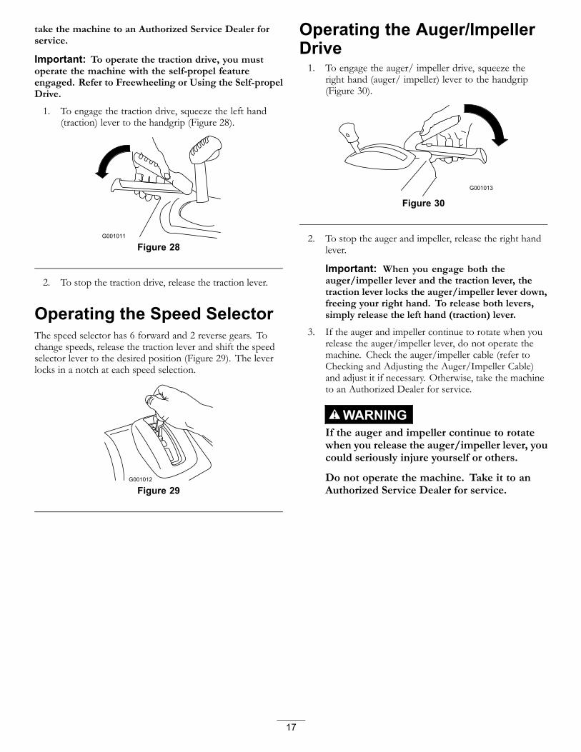
Operating the Auger/ImpellerDrive1. To engage the auger/ impeller drive, squeeze the
right hand (auger/ impeller) lever to the handgrip(Figure 30).
Figure 30
2. To stop the auger and impeller, release the right handlever.
Important: When you engage both theauger/impeller lever and the traction lever, thetraction lever locks the auger/impeller lever down,freeing your right hand. To release both levers,simply release the left hand (traction) lever.
3. If the auger and impeller continue to rotate when yourelease the auger/impeller lever, do not operate themachine. Check the auger/impeller cable (refer toChecking and Adjusting the Auger/Impeller Cable)and adjust it if necessary. Otherwise, take the machineto an Authorized Dealer for service.
WARNINGIf the auger and impeller continue to rotatewhen you release the auger/impeller lever, youcould seriously injure yourself or others.
Do not operate the machine. Take it to anAuthorized Service Dealer for service.
17

Operating the Quick Lever
Moving the Discharge ChutePush the Quick Lever forward; move the Quick Lever tothe left to move the discharge chute to the left; move theQuick Lever to the right to move the discharge chute to theright. Release the lever to lock the discharge chute in place(Figure 31).
g018897
Figure 31
• If the chute does not move, refer to Adjusting theDischarge Chute Latch.
• If the chute does not lock into place when you release thelever, refer to Adjusting the Discharge Chute Latch.
Moving the Chute DeflectorTo raise or lower the angle of the chute deflector, press thetrigger on the chute deflector and move the chute deflectorup or down (Figure 32).
g018898
Figure 32
1. Chute deflector trigger 2. Chute deflector
Unclogging the DischargeChute
WARNINGIf the auger/impeller is running but there is nosnow coming out of the discharge chute, thedischarge chute may be clogged.
Never use your hands to clear a clogged dischargechute. This could result in personal injury.
• To unclog the discharge chute, stay in the operatingposition and release the left hand (traction) lever. Whilerunning the auger/impeller, push down on the handles toraise the front of the machine a few inches (centimeters)off the pavement. Then lift the handles quickly to bumpthe front of the machine on the pavement. Repeat ifnecessary until a stream of snow comes out the dischargechute.
• If you cannot unclog the discharge chute by bumpingthe front of the machine, stop the engine, wait for allmoving parts to stop, and use the snow cleanout tool;never use your hand.
Important: Unclogging the discharge chute bybumping the front of the machine on the pavementmay cause the skids to move. Adjust the skids andtighten the skid bolts securely.
Preventing Freeze-up• In snowy and cold conditions, some controls and moving
parts may freeze. Do not use excessive force whentrying to operate frozen controls. If you have difficultyoperating any control or part, start the engine and let itrun for a few minutes.
• After using the machine, let the engine run for a fewminutes to prevent moving parts from freezing. Engagethe auger/impeller to clear any remaining snow frominside the housing. Rotate the Quick Stick to prevent itfrom freezing. Stop the engine, wait for all moving partsto stop, and remove all ice and snow from the machine.
• With the engine off, pull the recoil starter handle severaltimes and push the electric-starter button once to preventthe recoil and electric starters from freezing up.
18
Operating TipsDANGER
When the machine is in operation, the impeller andauger can rotate and cut off or injure hands and feet.
• Before adjusting, cleaning, inspecting,troubleshooting, or repairing the machine, stopthe engine and wait for all moving parts to stop.Disconnect the wire from the spark plug andkeep it away from the plug to prevent someonefrom accidentally starting the engine.
• Remove an obstruction from the dischargechute; refer to Unclogging the Discharge Chute.If necessary, use the snow cleanout tool, notyour hands, to remove an obstruction from thedischarge chute.
• Stay behind the handles and away from thedischarge opening while operating the machine.
• Keep face, hands, feet, and any other part ofyour body or clothing away from concealed,moving, or rotating parts.
WARNINGThe impeller can throw stones, toys, and otherforeign objects and cause serious personal injury tothe operator or to bystanders.
• Keep the area to be cleared free of all objectsthat the auger could pick up and throw.
• Keep all children and pets away from the areaof operation.
• Always set the throttle to the Fast position when throwingsnow.
• If the engine slows down under a load or the wheels slip,shift the machine into a lower gear.
• If the front of the machine rides up, shift the machineinto a lower gear. If the front continues to ride up, lift upon the handles.
19

MaintenanceNote: Determine the left and right sides of the machine from the normal operating position.
Recommended Maintenance Schedule(s)Maintenance Service
Interval Maintenance Procedure
After the first 2 hours • Inspect the traction cable and adjust it if necessary.• Inspect the auger/impeller cable and adjust it if necessary.
After the first 5 hours • Change the engine oil.
Before each use or daily • Check the engine oil level and add oil if necessary.
Every 25 hours • Change the engine oil.
Every 100 hours • Replace the spark plug.
Yearly
• Check the skids and the scraper and adjust them if necessary.• Inspect the traction cable and adjust or replace it if necessary.• Inspect the auger/impeller cable and adjust or replace it if necessary.• Check the auger gearbox oil and add oil if necessary.• Lubricate the hex shaft.
Yearly or before storage
• Check the air pressure in the tires and inflate them to 17–20 psi (116–137 kPa).• Drain the gasoline and run the engine to dry out the fuel tank and the carburetor atthe end of the season.
• Have an Authorized Service Dealer inspect and replace the traction drive belt and/orthe auger/impeller drive belt, if necessary.
Important: You can find more information about maintaining and servicing your machine at www.Toro.com.
Important: Refer to your engine operator's manual for additional maintenance procedures. For engine adjustments,repairs, or warranty service not covered in this manual, contact an Authorized Briggs & Stratton Servicing Dealer.
Preparing for Maintenance1. Move the machine to a level surface.
2. Stop the engine and wait for all moving parts to stop.
3. Disconnect the spark plug wire. Refer to Replacingthe Spark Plug.
Checking the Engine Oil LevelService Interval: Before each use or daily—Check the engine
oil level and add oil if necessary.
1. Remove the dipstick, wipe it clean, then fully installthe dipstick.
2. Remove the dipstick and check the oil level (Figure 33).If the oil level is below the Add mark on the dipstick,add oil. Refer to Filling the Engine with Oil.
g018886
Figure 33
20

Checking and Adjusting theSkids and ScraperService Interval: Yearly—Check the skids and the scraper
and adjust them if necessary.
Check the skids and the scraper to ensure that the auger doesnot contact the paved or gravel surface. Adjust the skids andthe scraper as needed to compensate for wear.
1. Check the tire pressure. Refer to Checking the TirePressure.
2. Loosen the nuts that secure both skids to the augersides until the skids slide up and down easily (Figure 34).
g0190461
Figure 34
1. 1/8 inch (3 mm)
Important: The auger blades must be supportedabove the ground by the skids.
3. Ensure that the scraper is 1/8 inch (3 mm) above andparallel to a level surface.
Note: If the pavement is cracked, rough, or uneven,adjust the skids to raise the scraper. For gravel surfaces,adjust the skids further down to prevent the machinefrom picking up rocks.
4. Move the skids down until they are even with theground.
5. Firmly tighten the nuts that secure both skids to theauger sides.
Note: To quickly adjust the skids if they loosen,support the scraper 1/8 inch (3 mm) off the pavement,then adjust the skids down to the pavement.
Note: If the skids become excessively worn, you canturn them over and set the unused side toward thepavement.
Checking and Adjusting theTraction CableService Interval: After the first 2 hours—Inspect the
traction cable and adjust it if necessary.
Yearly—Inspect the traction cable andadjust or replace it if necessary.
If the machine does not drive in the forward or reverse speedsor it drives when you release the traction lever, adjust thetraction cable.
If the left hand (traction) cable is not properly adjusted, dothe following steps:
1. Loosen the jam nut.
2. Engage the traction lever and hold it in place(Figure 35).
Figure 35
3. Loosen or tighten the turnbuckle to adjust the springlength to 2.18 inches (5.5 cm).
3
g019048
4
Figure 36
1. Jam nut 3. Spring2. Turnbuckle 4. 2.18 inches (5.5 cm)
21

4. Tighten the jam nut (Figure 36), ensuring there is slighttension on the cable.
5. If the traction cable is properly adjusted but a problemremains, contact an Authorized Service Dealer.
Checking and Adjusting theAuger/Impeller CableService Interval: After the first 2 hours—Inspect the
auger/impeller cable and adjust it ifnecessary.
Yearly—Inspect the auger/impeller cableand adjust or replace it if necessary.
1. Loosen the jam nut.
2. Engage the auger/impeller lever and hold it in place(Figure 37).
Figure 37
3. Loosen or tighten the turnbuckle to adjust the springlength to 2.75 inches (7 cm) (Figure 38).
21
3
g019047
4
Figure 38
1. Jam nut 3. Spring2. Turnbuckle 4. 2.75 inches (7 cm)
4. Tighten the jam nut (Figure 38), ensuring there is slighttension on the cable.
5. If the auger/impeller cable is properly adjusted buta problem remains, contact an Authorized ServiceDealer.
22
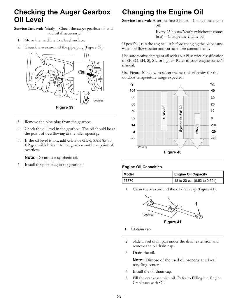
Checking the Auger GearboxOil LevelService Interval: Yearly—Check the auger gearbox oil and
add oil if necessary.
1. Move the machine to a level surface.
2. Clean the area around the pipe plug (Figure 39).
Figure 39
3. Remove the pipe plug from the gearbox.
4. Check the oil level in the gearbox. The oil should be atthe point of overflowing at the filler opening.
5. If the oil level is low, add GL-5 or GL-6, SAE 85-95EP gear oil lubricant to the gearbox until the point ofoverflow.
Note: Do not use synthetic oil.6. Install the pipe plug in the gearbox.
Changing the Engine OilService Interval: After the first 5 hours—Change the engine
oil.
Every 25 hours/Yearly (whichever comesfirst)—Change the engine oil.
If possible, run the engine just before changing the oil becausewarm oil flows better and carries more contaminants.
Use automotive detergent oil with an API service classificationof SF, SG, SH, SJ, SL, or higher. Refer to your engine owner'smanual.
Use Figure 40 below to select the best oil viscosity for theoutdoor temperature range expected:
g019049
Figure 40
Engine Oil Capacities
Model Engine Oil Capacity
37770 18 to 20 oz. (0.53 to 0.59 l)
1. Clean the area around the oil drain cap (Figure 41).
Figure 41
1. Oil drain cap
2. Slide an oil drain pan under the drain extension andremove the oil drain cap.
3. Drain the oil.
Note: Dispose of the used oil properly at a localrecycling center.
4. Install the oil drain cap.
5. Fill the crankcase with oil. Refer to Filling the EngineCrankcase with Oil.
23

Lubricating the Hex ShaftService Interval: Yearly—Lubricate the hex shaft.
Lightly lubricate the hex shaft yearly with automotive engineoil (Figure 42).
g019018
Figure 42
1. Hex shaft 3. Rubber wheel2. Steel friction pulley
Important: Do not get oil on the rubber wheel or thesteel friction pulley because the traction drive will slip(Figure 42).1. Drain the gasoline from the fuel tank.2. Tip the machine forward onto its auger housing and
block it so that it cannot fall.3. Remove the lower cover by removing the 4 screws
securing it to the frame (Figure 43).
g019019
1
Figure 43
1. Screws
4. Move the speed selector lever to Position R2.5. Dip your finger in automotive engine oil and lightly
lubricate hex shaft.6. Move the speed selector lever to Position 6.7. Lubricate the other end of the hex shaft.8. Move the speed selector lever forward and rearward
a few times.
9. Install the lower cover and return the machine to theoperating position.
Replacing the Spark PlugService Interval: Every 100 hours—Replace the spark plug.
Use a Champion QC12YC or equivalent spark plug.
Note: To access the spark plug, you must first remove theupper snow hood (Figure 44).
Figure 44
1. Choke knob 3. Ignition key2. Upper snow hood 4. Screw (2)
1. Remove the choke knob and the ignition key(Figure 44).
2. Remove the 2 screws that secure the upper snow hoodto the machine (Figure 44).
3. Slowly remove the upper snow hood, ensuring thatthe primer bulb hose and the ignition wire remainconnected.
4. Remove the bracket thumb screw and the bracket(Figure 45).
24

Figure 45
1. Spark-plug wire 3. Thumb screw2. Bracket
5. Clean around the base of the spark plug (Figure 45).
6. Remove and discard the old spark plug.
Note: You will need a ratchet wrench extension toremove the spark plug.
7. Set the gap between the electrodes on a new spark plugat 0.030 inch (0.76 mm) (Figure 46).
Figure 46
1. 0.030 inch (0.76 mm)
8. Install the new spark plug, tighten it firmly, and attachthe ignition wire to the spark plug.
9. Install the bracket with the thumb screw that youremoved in step 4.
10. Ensure that the primer bulb hose and the ignition wireare connected and clear of the carburetor bracket.
11. Secure the upper snow hood to the machine with the 2screws that you previously removed.
12. Align the tab on the choke control knob with the sloton the upper snow hood.
13. Connect the choke control knob to the choke shaft onthe carburetor.
Adjusting the Discharge ChuteLatchIf the discharge chute does not lock into the desired positionor does not unlock so that you can move it to anotherposition, adjust the discharge chute latch.
1. Loosen the clamp fastener on the chute support plateuntil the cable is free.
g019021
1
23
Figure 47
1. Cable conduit 3. Clamp fastener2. Cable clamp
2. Remove any slack in the cable by pulling the cableconduit rearward.
3. Tighten the clamp fastener while holding the cable inplace.
Replacing the Drive BeltsIf the auger/impeller drive belt or the traction drive beltbecomes worn, oil-soaked, or otherwise damaged, have anAuthorized Service Dealer replace the belt.
25

StorageWARNING
• Gasoline vapors can explode.
• Do not store gasoline more than 30 days.
• Do not store the machine in an enclosure nearan open flame.
• Allow the engine to cool before storing it.
Preparing the Machine forStorage1. On the last refueling of the year, add fuel stabilizer to
fresh fuel as directed by the engine manufacturer.
Note: Fuel should not be stored longer than suggestedby the fuel stabilizer manufacturer.
2. Run the engine for 10 minutes to distribute theconditioned fuel through the fuel system.
3. Run the machine until the engine runs out of fuel.
4. Prime the engine and start it again.
5. Allow the engine to run until it stops. When you canno longer start the engine, it is sufficiently dry.
6. Stop the engine and allow it to cool.
7. Remove the ignition key.
8. Clean the machine thoroughly.
9. Touch up chipped surfaces with paint available from anAuthorized Service Dealer. Sand affected areas beforepainting, and use a rust preventative to prevent themetal parts from rusting.
10. Tighten all loose screws, bolts, and locknuts. Repair orreplace any damaged parts.
11. Cover the machine and store it in a clean, dry place outof the reach of children.
Removing the Machine fromStorage1. Remove the spark plug and spin the engine rapidly
using the starter to blow the excess oil from thecylinder.
2. Install the spark plug and tighten it firmly.
3. Connect the spark plug wire.
4. Perform the annual maintenance procedures as givenin the Recommended Maintenance Schedule.
26

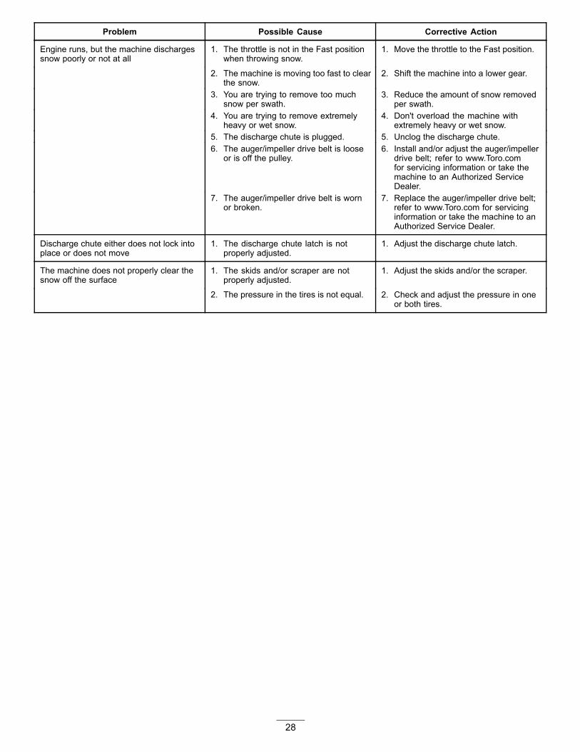
TroubleshootingProblem Possible Cause Corrective Action
1. The power cord is disconnected at theoutlet or the machine.
1. Connect the power cord to the outletand/or the machine.
2. The power cord is worn, corroded, ordamaged.
2. Replace the power cord.
Electric starter does not turn (electric-startmodels only)
3. The power outlet is not energized. 3. Have a qualified electrician energizethe outlet.
1. The key is not in the ignition or is in theStop position.
1. Insert the key into the ignition and turnit to the On position.
2. The choke is in the Off position and theprimer has not been pressed.
2. Move the choke to the On position andpress the primer 3 times.
3. The fuel shutoff valve is not open. 3. Open the fuel shutoff valve.4. The throttle is not in the Fast position. 4. Move the throttle to the Fast position.5. The fuel tank is empty or the fuel
system contains stale fuel.5. Drain and/or fill the fuel tank with fresh
gasoline (not more than 30 days old).If the problem persists, contact anAuthorized Service Dealer.
6. The spark plug wire is loose ordisconnected.
6. Connect the wire to the spark plug.
7. The spark plug is pitted, fouled, or thegap is incorrect.
7. Check the spark plug and adjust thegap if necessary. Replace the sparkplug if it is pitted, fouled, or cracked.
8. The fuel vent cap is restricted. 8. Remove the vent restriction or replacethe fuel cap.
Engine does not start or starts hard
9. The engine oil level in the enginecrankcase is too low or too high.
9. Add or drain oil to adjust the oil level inthe engine crankcase to the Full markon the dipstick.
1. The choke is in the On position. 1. Move the choke to the Off position.
2. The fuel shutoff valve is not completelyopen.
2. Open the fuel shutoff valve.
3. The fuel tank is nearly empty orcontains stale fuel.
3. Drain and fill the fuel tank with freshgasoline (not more than 30 days old).If the problem persists, contact anAuthorized Service Dealer.
4. The spark plug wire is loose. 4. Connect the wire to the spark plug.5. The spark plug is pitted, fouled, or the
gap is incorrect.5. Check the spark plug and adjust the
gap if necessary. Replace the sparkplug if it is pitted, fouled, or cracked.
Engine runs rough
6. The engine oil level in the enginecrankcase is too low or too high.
6. Add or drain oil to adjust the oil level inthe engine crankcase to the Full markon the dipstick.
27
Problem Possible Cause Corrective Action
1. The throttle is not in the Fast positionwhen throwing snow.
1. Move the throttle to the Fast position.
2. The machine is moving too fast to clearthe snow.
2. Shift the machine into a lower gear.
3. You are trying to remove too muchsnow per swath.
3. Reduce the amount of snow removedper swath.
4. You are trying to remove extremelyheavy or wet snow.
4. Don't overload the machine withextremely heavy or wet snow.
5. The discharge chute is plugged. 5. Unclog the discharge chute.6. The auger/impeller drive belt is loose
or is off the pulley.6. Install and/or adjust the auger/impeller
drive belt; refer to www.Toro.comfor servicing information or take themachine to an Authorized ServiceDealer.
Engine runs, but the machine dischargessnow poorly or not at all
7. The auger/impeller drive belt is wornor broken.
7. Replace the auger/impeller drive belt;refer to www.Toro.com for servicinginformation or take the machine to anAuthorized Service Dealer.
Discharge chute either does not lock intoplace or does not move
1. The discharge chute latch is notproperly adjusted.
1. Adjust the discharge chute latch.
1. The skids and/or scraper are notproperly adjusted.
1. Adjust the skids and/or the scraper.The machine does not properly clear thesnow off the surface
2. The pressure in the tires is not equal. 2. Check and adjust the pressure in oneor both tires.
28

Notes:
29

Emission Control Warranty StatementFor the United States, California, and Canada
A Two-Year Limited Warranty
Your Warranty Rights and ObligationsThe California Air Resources Board (CARB), the U.S. Environmental Protection Agency (EPA), and The Toro Company, are pleased to explain theemission control system warranty on your 2012 –2013 small off-road engine/equipment. In California and the United States, new small off-roadengines/equipment must be designed, built, and certified to meet stringent anti-smog standards. The Toro Company warrants the emission controlsystem on your small off-road engine/equipment for the period of time listed above, provided there has been no abuse, neglect, or improper maintenanceof your small off-road engine/equipment.
Your emission control system may include parts such as the carburetor, fuel-injection system, the ignition system, catalytic converter, fuel tanks, fuel lines,fuel caps, valves, canisters, filters, vapor hoses, clamps, connectors, and other associated emission-related components.
Where a warrantable condition exists, The Toro Company will repair your small off-road engine/equipment at no cost to you including diagnosis,parts and labor.
Manufacturer’s Warranty CoverageThe Toro Company and its affiliate, Toro Warranty Company, pursuant to an agreement between them, jointly warrant the 2012–2013 small off-roadengine/equipment for two years from the date of delivery. If any emission-related part on your engine/equipment is defective, the part will be repaired orreplaced by The Toro Company.
Owner ResponsibilitiesAs the small off-road engine owner, you are responsible for the performance of the required maintenance listed in your Operator's Manual. We recommendthat you retain all receipts covering maintenance on your small off-road engine/equipment, but we cannot deny warranty solely for the lack of receipts.
As the small off-road engine/equipment owner, you should however be aware that we may deny you warranty coverage if your small off-roadengine/equipment or a part has failed due to abuse, neglect, improper maintenance or unapproved modifications.
You are responsible for presenting your small off-road engine/equipment to an Authorized Service Dealer as soon as a problem exists. The warrantyrepairs should be completed in a reasonable amount of time, not to exceed thirty (30) days.
If you have any questions regarding your warranty coverage, contact us at:
Customer Care Department, Consumer DivisionToro Warranty Company8111 Lyndale Avenue SouthBloomington, MN 55420-1196Toll free at 800–348–2424 (U.S. customers)Toll free at 800–544–5364 (Canadian customers)
General Emissions Warranty CoverageThe Toro Company and its affiliate, Toro Warranty Company, jointly warrant to the initialowner and each subsequent purchaser that the small off-road engine/equipment is:
• Designed, built, and certified to conform with all applicable emissions regulations; and• Free from defects in materials and workmanship that could cause the failure of a warranted part; and• Identical in all material respects to the parts as described in the application for certification.
The warranty period begins on the date the small off-road engine/equipment is delivered to an ultimate purchaser. The warranted period is two years.
Subject to certain conditions and exclusions as stated below, the warranty on evaporative emissions-related parts is as follows:
1. Any warranted part that is not scheduled for replacement as required maintenance in the written instructions supplied, is warrantedfor the warranty period stated above. If the part fails during the period of warranty coverage, the part will be repaired or replaced byThe Toro Company. Any such part repaired or replaced under warranty will be warranted for the remainder of the warranty period.2. Any warranted part that is scheduled only for regular inspection in the written instructions supplied is warranted for the warrantyperiod stated above. Any such part repaired or replaced under the warranty will be warranted for the remainder of the warranty period.3. Any warranted part that is scheduled for replacement as required maintenance in the written instructions supplied iswarranted for the period of time before the first scheduled replacement date for that part. If the part fails before the firstscheduled replacement, the part will be repaired or replaced by The Toro Company. Any such part repaired or replacedunder warranty will be warranted for the remainder of the period prior to the first scheduled replacement point for the part.4. Repair or replacement of any warranted part under the warranty provisions herein must be performed at anAuthorized Service Dealer at no charge to the owner.5. Notwithstanding the provisions herein, warranty services or repairs will be provided at all Service Dealersauthorized to service the subject engines or equipment.6. The small off-road engine/equipment owner will not be charged for diagnostic labor that is directly associated with diagnosisof a defective, emission-related warranted part, provided that such diagnostic work is performed at an Authorized Service Dealer.7. The Toro Company is liable for damages to other engine/equipment components caused by a failure under warranty of any emissions part.8. Throughout the small off-road engine/equipment warranty period stated above, The Toro Companywill maintain a supply of warranted parts sufficient to meet the expected demand for such parts.9. Manufacturer approved replacement parts may be used in the performance of any warranty maintenance or repairs andmust be provided without charge to the owner. Such use will not reduce the warranty obligations of The Toro Company.10. Add-on or modified parts that are not approved by The Toro Company may not be used. The use of a non-approved add-on or modified partsby the purchaser will be grounds for disallowing a warranty claim. The Toro Company will not be liable to warrant failures of warranted partscaused by the use of an non-approved add-on or modified parts.
Warranted PartsThe following emission warranty parts are covered, to the extent these parts were present on the Toro engine/equipment and/or Toro supplied fuel system:
374-0287 Rev A

1. Fuel System Parts
• Carburetor and internal parts
• Cold starting enrichment (primer or choke)
• Fuel pump
• Fuel line, fittings, and clamps
• Fuel tank, cap, and tether
• Carbon canister
2. Air Induction System
• Air cleaner
• Intake manifold
• Crankcase vent and line(s)
• Purge line and fittings
3. Ignition System
• Spark plug(s) and wire(s)
• Magneto ignition system
4. Catalytic Exhaust System
• Catalytic converter
• Exhaust manifold
• Air injector system and valve(s)
5. Miscellaneous Items Used in Emission Control System
• Valves, switches, and linkages
• Connectors, fittings, and brackets
374-0287 Rev A

Power Max HD andPower MaxTwo-Stage Snowthrowers
The Toro Total Coverage GuaranteeA Three-Year Limited Warranty (45 Day Limited Warranty for Commercial Use)
Conditions and Products CoveredThe Toro Company and its affiliate, Toro Warranty Company, pursuant toan agreement between them, jointly promise to repair the Toro Productlisted below if used for residential purposes*, if defective in materials orworkmanship or if it stops functioning due to the failure of a componentfor the period listed below.
This warranty covers the cost of parts and labor, but you must paytransportation costs.
The following time periods apply from the date of purchase:
Products Warranty Period`Power Max HD and Power Max Snowthrowersand Attachments
3 years
— Power Max HD and Power Max Chute Guaranteed for LifeWarranty (original owneronly)
— Power Max HD and Power Max Deflector Guaranteed for LifeWarranty (original owneronly)
— Power Max HD and Power MaxAnti-Clogging System
Guaranteed for LifeWarranty (original owneronly)
(Plastic Impeller Housing cover)
Limited Warranty for Commercial UseGas-powered Toro Products used for commercial, institutional, orrental use, are warranted for 45 days against defects in materials orworkmanship. Components failing due to normal wear are not coveredby this warranty.
Instructions for Obtaining Warranty ServiceIf you think that your Toro Product contains a defect in materials orworkmanship, follow this procedure:
1. Contact any Authorized Toro Service Dealer to arrange serviceat their dealership. To locate a dealer convenient to you, refer tothe Yellow Pages of your telephone directory (look under “LawnMowers”) or access our web site at www.Toro.com. You may alsocall the numbers listed in item #3 to use the 24-hour Toro Dealerlocator system.
2. Bring the product and your proof of purchase (sales receipt) to theService Dealer. The dealer will diagnose the problem and determineif it is covered under warranty.
3. If for any reason you are dissatisfied with the Service Dealer’sanalysis or with the assistance provided, contact us at:
Customer Care Department, Consumer DivisionThe Toro Company8111 Lyndale Avenue SouthBloomington, MN 55420-1196Toll free at 866-336-5205 (U.S. customers)Toll free at 866-854–9033 (Canadian customers)
Owner ResponsibilitiesYou must maintain your Toro Product by following the maintenanceprocedures described in the Operator's Manual. Such routinemaintenance, whether performed by a dealer or by you, is at your expense.
Items and Conditions Not CoveredThere is no other express warranty except for special emission systemcoverage and engine warranty coverage on some products. This expresswarranty does not cover the following:
• Cost of regular maintenance service or replacement of wear parts,such as rotor blades (paddles), scraper blades, belts, fuel, lubricants,oil changes, spark plugs, cable/linkage or brake adjustments
• Any product or part which has been altered or misused and requiresreplacement or repair due to accidents or lack of proper maintenance
• Repairs necessary due to failure to use fresh fuel (less than onemonth old), or failure to properly prepare the unit prior to any periodof non-use over one month
• Pickup and delivery charges
• Operational misuse, neglect, or accidents
• Repairs or attempted repairs by anyone other than an AuthorizedToro Service Dealer
General ConditionsAll repairs covered by these warranties must be performed by anAuthorized Toro Service Dealer using Toro approved replacement parts.Repair by an Authorized Toro Service Dealer is your sole remedy underthis warranty.
Neither The Toro Company nor Toro Warranty Company is liable forindirect, incidental, or consequential damages in connection with theuse of the Toro Products covered by these warranties, including anycost or expense of providing substitute equipment or service duringreasonable periods of malfunction or non-use pending completion ofrepairs under these warranties.
All implied warranties of merchantability (that the product is fit for ordinaryuse) and fitness for use (that the product is fit for a particular purpose) arelimited to the duration of the expressed warranty.
Some states do not allow exclusions of incidental or consequentialdamages, or limitations on how long an implied warranty lasts, so theabove exclusions may not apply to you.
This warranty gives you specific legal rights, and you may also have otherrights which vary from state to state.
Countries Other than the United States or CanadaCustomers who have purchased Toro products exported from the United States or Canada should contact their Toro Distributor (Dealer) to obtainguarantee policies for your country, province, or state. If for any reason you are dissatisfied with your Distributor's service or have difficulty obtainingguarantee information, contact the Toro importer. If all other remedies fail, you may contact us at Toro Warranty Company.
Australian Consumer LawAustralian customers will find details relating to the Australian Consumer Law either inside the box or at your local Toro Dealer.
*Residential purposes means use of the product on the same lot as your home. Use at more than one location, or institutional or rental use, is consideredcommercial use, and the commercial use warranty would apply.
374-0251 Rev D