Embed Size (px)
Citation preview

WORKING DOCUMENT
STAKEHOLDER EXPERIENCE WITH REGULATIONS 2016/427 AND 2016/646
–COMMENTS APPEAR IN OVER-TYPE MODE AND IN DEDICATED
TEXT BOXES; COMMENTS EXPRESS THE VIEWS OF STAKEHOLDERS BUT MAY NOT BE REGARDED AS THE POSITION OF THE EUROPEAN
COMMISSION
EN EN
EUROPEAN COMMISSION
Brussels, XXX […](2016) XXX draft
ANNEX 3 – PART 1/3
ANNEX
to the
Commission Regulation
supplementing Regulation (EC) No 715/2007 of the European Parliament and of the Council on type-approval of motor vehicles with respect to emissions from light
passenger and commercial vehicles (Euro 5 and Euro 6) and on access to vehicle repair and maintenance information, amending Directive 2007/46/EC of the European Parliament and of the Council, Commission Regulation (EC) No 692/2008 and
Commission Regulation (EU) No 1230/2012 and repealing Regulation (EC) No 692/2008

ANNEX III
[Reserved]
General comment: Amendment of unexpected regulation issues
During the transitional period unexpected problems in applying the RDE regulation may be revealed. Such problems could be the reason for denial of approval. Would in such cases a text update at short notice be possible?
“ANNEX IIIAVERIFYING REAL DRIVING EMISSIONS
1. INTRODUCTION, DEFINITIONS AND ABBREVIATIONS
1.1. Introduction
This Annex describes the procedure to verify the Real Driving Emissions (RDE) performance of light passenger and commercial vehicles.
1.2. Definitions
1.2.1. “Accuracy” means the deviation between a measured or calculated value and a traceable reference value.
1.2.2. “Analyser” means any measurement device that is not part of the vehicle but installed to determine the concentration or the amount of gaseous or particle pollutants.
1.2.3. “Axis intercept” of a linear regression (a0) means:
a0= y−( a1 × x )
where:
a1 is the slope of the regression line
x is the mean value of the reference parameter
y is the mean value of the parameter to be verified
1.2.4. “Calibration” means the process of setting the response of an analyser, flow-measuring instrument, sensor, or signal so that its output agrees with one or multiple reference signals.
107

1.2.5. “Coefficient of determination” (r2) means:
r2=1−∑i=1
n
[ y i−a0−(a1× x i ) ]2
∑i=1
n
( y i− y )2
where:
a0 is the axis intercept of the linear regression line
a1 is the slope of the linear regression line
xi is the measured reference value
yi is the measured value of the parameter to be verified
y is the mean value of the parameter to be verified
is the number of values
1.2.6. “Cross-correlation coefficient” (r) means:
where:
xi is the measured reference value
yi is the measured value of the parameter to be verified
x is the mean reference value
y is the mean value of the parameter to be verified
is the number of values
1.2.7. “Delay time” means the time from the gas flow switching (t0) until the response reaches 10 per cent (t10) of the final reading.
1.2.8. "Engine control unit (ECU) signals or data" means any vehicle information and signal recorded from the vehicle network using the protocols specified in point 3.4.5.of Appendix 1.
108

1.2.9. “Engine control unit” means the electronic unit that controls various actuators to ensure the optimal performance of the powertrain.
1.2.10. "Emissions" also referred to as "components", "pollutant components" or "pollutant emissions" means the regulated gaseous or particle constituents of the exhaust.
1.2.11. “Exhaust”, also referred to as exhaust gas, means the total of all gaseous and particulate components emitted at the exhaust outlet or tailpipe as the result of fuel combustion within the vehicle’s internal combustion engine.
1.2.12. “Exhaust emissions” means the emissions of particles, characterized as particulate matter and particle number, and of gaseous components at the tailpipe of a vehicle.
1.2.13. “Full scale” means the full range of an analyser, flow-measuring instrument or sensor as specified by the equipment manufacturer. If a sub-range of the analyser, flow-measuring instrument or sensor is used for measurements, full scale shall be understood as the maximum reading.
1.2.14. “Hydrocarbon response factor” of a particular hydrocarbon species means the ratio between the reading of a FID and the concentration of the hydrocarbon species under consideration in the reference gas cylinder, expressed as ppmC1.
1.2.15. “Major maintenance” means the adjustment, repair or replacement of an analyser, flow-measuring instrument or sensor that could affect the accuracy of measurements.
1.2.16. “Noise” means two times the root mean square of ten standard deviations, each calculated from the zero responses measured at a constant recording frequency of at least 1.0 Hz during a period of 30 seconds.
ACEA recommends to use a fixed frequency of 1 Hz in order to minimize interference with the provisions of the other Appendices (particularly Appendix 6) and to facilitate post-processing of the data.
109

1.2.17. “Non-methane hydrocarbons” (NMHC) means the total hydrocarbons (THC) excluding methane (CH4).
1.2.18. “Particle number” (PN) means as the total number of solid particles emitted from the vehicle exhaust as defined by the measurement procedure provided for by this Regulation for assessing compliance with the respective Euro 6 emission limit defined in Table 2 of Annex I to Regulation 715/2007. “Particle number emissions" (PN) means the total number of solid particles emitted from the vehicle exhaust quantified according to the dilution, sampling and measurement methods as specified in this Annex.
Typo correction: Delete “as”.The additional text was adopted by TCMV on 14.06.2016 in Regulation XXX/2016 (WLTP).
1.2.19. “Precision” means 2.5 times the standard deviation of 10 repetitive responses to a given traceable standard value.
1.2.20. “Reading” means the numerical value displayed by an analyser, flow-measuring instrument, sensor or any other measurement devise applied in the context of vehicle emission measurements.
1.2.21. “Response time” (t90) means the sum of the delay time and the rise time.
1.2.22. “Rise time” means the time between the 10 per cent and 90 per cent response (t90 – t10) of the final reading.
1.2.23. “Root mean square” (xrms) means the square root of the arithmetic mean of the squares of values and defined as:
xrms=√ 1n (x1
2+ x22+...+xn
2 )
where:
x is the measured or calculated value
n is the number of values
110

1.2.24. “Sensor” means any measurement device that is not part of the vehicle itself but installed to determine parameters other than the concentration of gaseous and particle pollutants and the exhaust mass flow.
1.2.25. “Span” means the calibration of an analyser, flow-measuring instrument, or sensor so that it gives an accurate response to a standard that matches as closely as possible the maximum value expected to occur during the actual emissions test.
1.2.26. “Span response” means the mean response to a span signal over a time interval of at least 30 seconds.
1.2.27. “Span response drift” means the difference between the mean response to a span signal and the actual span signal that is measured at a defined time period after an analyser, flow-measuring instrument or sensor was accurately spanned.
1.2.28. “Slope” of a linear regression (a1) means:
a1=∑i=1
n
( y i− y ) × ( xi−x )
∑i=1
n
( x i− x )2
where:
x is the mean value of the reference parameter
y is the mean value of the parameter to be verified
xi is the actual value of the reference parameter
yi is the actual value of the parameter to be verified
n is the number of values
1.2.29. “Standard error of estimate” (SEE) means:
111

where:
y is the estimated value of the parameter to be verified
yi is the actual value of the parameter to be verified
xmax is the maximum actual value of the reference parameter
n is the number of values
1.2.30. “Total hydrocarbons” (THC) means the sum of all volatile compounds measurable by a flame ionization detector (FID).
1.2.31 “Traceable” means the ability to relate a measurement or reading through an unbroken chain of comparisons to a known and commonly agreed standard.”
1.2.32. “Transformation time” means the time difference between a change of concentration or flow (t0) at the reference point and a system response of 50 per cent of the final reading (t50).
1.2.33. “Type of analyser”, also referred to as “analyser type” means a group of analysers produced by the same manufacturer that apply an identical principle to determine the concentration of one specific gaseous component or the number of particles.
1.2.34. “Type of exhaust mass flow meter” means a group of exhaust mass flow meters produced by the same manufacturer that share a similar tube inner diameter and function on an identical principle to determine the mass flow rate of the exhaust gas.
1.2.35. “Validation” means the process of evaluating the correct installation and functionality of a Portable Emissions Measurement System and the correctness of exhaust mass flow rate measurements as obtained from one or multiple non-traceable exhaust mass flow meters or as calculated from sensors or ECU signals.
112

1.2.36.“Verification” means the process of evaluating whether the measured or calculated output of an analyser, flow-measuring instrument, sensor or signal agrees with a reference signal within one or more predetermined thresholds for acceptance.
1.2.37. “Zero” means the calibration of an analyser, flow-measuring instrument or sensor so that it gives an accurate response to a zero signal.
1.2.38. “Zero response” means the mean response to a zero signal over a time interval of at least 30 seconds.
1.2.39. “Zero response drift” means the difference between the mean response to a zero signal and the actual zero signal that is measured over a defined time period after an analyser, flow-measuring instrument or sensor has been accurately zero calibrated.
1.3. Abbreviations
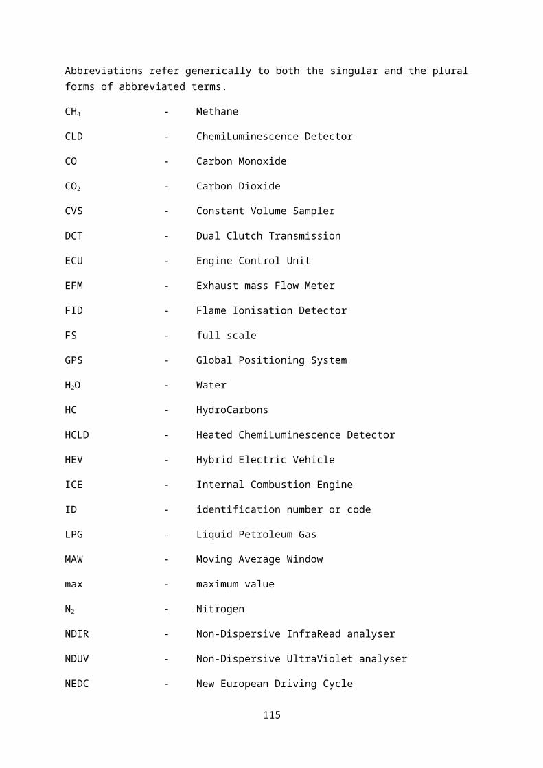
Abbreviations refer generically to both the singular and the plural forms of abbreviated terms.
CH4 - Methane
CLD - ChemiLuminescence Detector
CO - Carbon Monoxide
CO2 - Carbon Dioxide
CVS - Constant Volume Sampler
DCT - Dual Clutch Transmission
ECU - Engine Control Unit
EFM - Exhaust mass Flow Meter
FID - Flame Ionisation Detector
FS - full scale
GPS - Global Positioning System
H2O - Water
HC - HydroCarbons
HCLD - Heated ChemiLuminescence Detector
113

HEV - Hybrid Electric Vehicle
ICE - Internal Combustion Engine
ID - identification number or code
LPG - Liquid Petroleum Gas
MAW - Moving Average Window
max - maximum value
N2 - Nitrogen
NDIR - Non-Dispersive InfraRead analyser
NDUV - Non-Dispersive UltraViolet analyser
NEDC - New European Driving Cycle
NG - Natural Gas
NMC - Non-Methane Cutter
NMC-FID - Non-Methane Cutter in combination with a Flame-Ionisation
Detector
NMHC - Non-Methane HydroCarbons
NO - Nitrogen Monoxide
No. - number
NO2 - Nitrogen Dioxide
NOX - Nitrogen Oxides
NTE - Not-to-exceed
O2 - Oxygen
OBD - On-Board Diagnostics
PEMS - Portable Emissions Measurement System
PHEV - Plug-in Hybrid Electric Vehicle
PN - particle number
RDE - Real Driving Emissions
RPA - Relative Positive Acceleration
114
SCR - Selective Catalytic Reduction
SEE - Standard Error of Estimate
THC - Total HydroCarbons
UN/ECE - United Nations Economic Commission for Europe
VIN - Vehicle Identification Number
WLTC - Worldwide harmonized Light vehicles Test Cycle
WWH-OBD - WorldWide Harmonised On-Board Diagnostics
115

2. GENERAL REQUIREMENTS
2.1 Not-to-exceed emission limits
Throughout the normal life of a vehicle type approved according to Regulation (EC) No 715/2007, its emissions determined in accordance with the requirements of this Annex and emitted at any possible RDE test performed in accordance with the requirements of this Annex, shall not be higher than the following pollutant-specific not-to-exceed (NTE) values:
NTEpollutant = CFpollutant x TF(p1,…, pn) x EURO-6,
where EURO-6 is the applicable Euro 6 emission limit laid down in Table 2 of Annex I to Regulation (EC) No 715/2007.
2.1.1 Final Conformity Factors
The conformity factor CFpollutant for the respective pollutant is specified as follows:
Pollutant Mass of oxides of nitrogen (NOx)
Number of particles (PN)
Mass of carbon monoxide (CO)(1)
Mass of total hydrocarbons (THC)
Combined mass of total hydrocarbons and oxides of nitrogen (THC + NOx)
CFpollutant 1 + margin with
margin = 0,5
to be determined
- - -
(1) CO emissions shall be measured and recorded at RDE tests.
margin is a parameter taking into account the additional measurement uncertainties introduced by the PEMS equipment, which are subject to an annual review and shall be revised as a result of the improved quality of the PEMS procedure or technical progress.
The margin of 0.5 set in the 2nd RDE package is wide compared to the current PEMS (in) accuracy, giving reason to start the review procedure already under the 4th RDE package.
If for PN the same approach were to be followed as for NOx, a reasonable 3rd package proposal would consist of a PN Conformity factor of 1.0 + margin for both the 1st and 2nd step, with an initial value of 0.5 for the margin given similar inaccuracy levels for NOx and PN PEMS equipment.
2.1.2 Temporary Conformity Factors
By way of exception to the provisions of point 2.1.1, during a period of 5 years and 4 months following the dates specified in Article 10(4) and (5) of Regulation (EC) 715/2007 and upon request of the manufacturer, the following temporary conformity factors may apply:
Pollutant Mass of oxides of
Number of particles
Mass of carbon
Mass of total hydrocarbons
Combined mass of total hydrocarbons
116

nitrogen (NOx)
(PN) monoxide (CO)(1)
(THC) and oxides of nitrogen (THC + NOx)
CFpollutant 2,1 to be determined
- - -
(1) CO emissions shall be measured and recorded at RDE tests.
The application of temporary conformity factors shall be recorded in the certificate of conformity of the vehicle.
2.1.3 Transfer functions
The transfer function TF(p1,…, pn) referred to in point 2.1 is set to 1 for the entire range of parameters pi (i = 1,…,n).
If the transfer function TF(p1,…, pn) is amended, this shall be done in a manner which is not detrimental to the environmental impact and the effectiveness of the RDE test procedures. In particular the following condition shall hold:
∫TF ( p1 ,…, pn )∗Q ( p1 ,…, p n )dp=∫Q ( p 1 ,…, pn ) dp
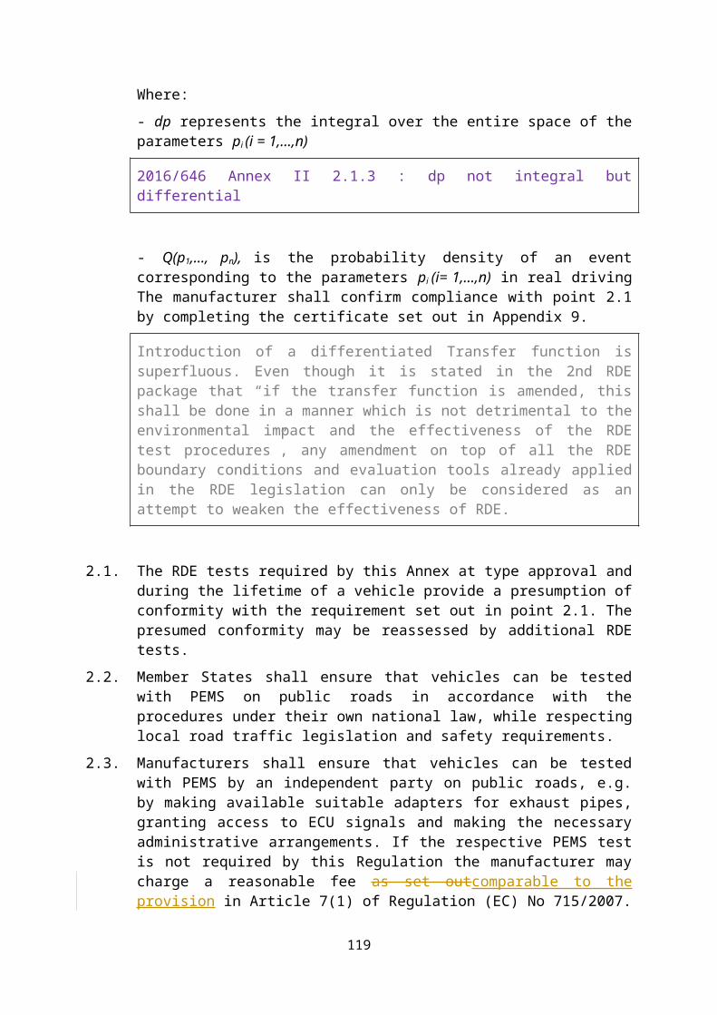
Where:
- dp represents the integral over the entire space of the parameters pi (i = 1,…,n)
2016/646 Annex II 2.1.3 : dp not integral but differential
- Q(p1,…, pn), is the probability density of an event corresponding to the parameters pi (i= 1,…,n) in real driving The manufacturer shall confirm compliance with point 2.1 by completing the certificate set out in Appendix 9.
Introduction of a differentiated Transfer function is superfluous. Even though it is stated in the 2nd RDE package that “if the transfer function is amended, this shall be done in a manner which is not detrimental to the environmental impact and the effectiveness of the RDE test procedures”, any amendment on top of all the RDE boundary conditions and evaluation tools already applied in the RDE legislation can only be considered as an attempt to weaken the effectiveness of RDE.
2.1. The RDE tests required by this Annex at type approval and during the lifetime of a vehicle provide a presumption of conformity with the requirement set out in point 2.1. The presumed conformity may be reassessed by additional RDE tests.
2.2. Member States shall ensure that vehicles can be tested with PEMS on public roads in accordance with the procedures under their own national law, while respecting local road traffic legislation and safety requirements.
[2.3.] Manufacturers shall ensure that vehicles can be tested with PEMS by an independent party on public roads, e.g. by making available suitable adapters for exhaust pipes, granting access to ECU signals and making the necessary administrative arrangements. If the respective PEMS test is not required by this Regulation the
117

manufacturer may charge a reasonable fee as set outcomparable to the provision in Article 7(1) of Regulation (EC) No 715/2007.
Article 7(1) is related only to repair and maintenance information.
3. RDE TEST TO BE PERFORMED
3.1. The following requirements apply to PEMS tests referred to in Article 3(10), second sub-paragraph.
3.1.1. The requirements of point 2.1 shall be fulfilled for the urban part and the complete PEMS trip. Upon the choice of the manufacturer the conditions of at least one of the two points below shall be fulfilled:
Article 3 (10) of consolidated regulation 692/2998/EC asks for two valid tests, if for example SPF method is invalid, ans “EMROAD” method is valid. In our case we provide the results of two tests. Sometimes the approval authority asks us, which is the final number, or valid test. In our opinion it is results from test number one, regardless if second result is higher or lower. But this can be discussed as well.
3.1.1.1. Mgas,d,t ≤ NTEpollutant and Mgas,d,u ≤ NTEpollutant with the definitions of point 2.1 of this Annex and points 6.1 and 6.3 of Appendix 5 and the setting gas = pollutant.
3.1.1.2. M w , gas, d ≤ NTEpollutant and M w , gas, d , U ≤ NTEpollutant with the definitions of point 2.1 of this Annex and point 3.9 of Appendix 6 and the setting gas = pollutant.
3.1.2. For type approval, the exhaust mass flow shall be determined by measurement equipment functioning independently from the vehicle and no vehicle ECU data shall be used in this respect. Outside the type approval context, alternative methods to determine the exhaust mass flow can be used according to Appendix 2, Section 7.2.
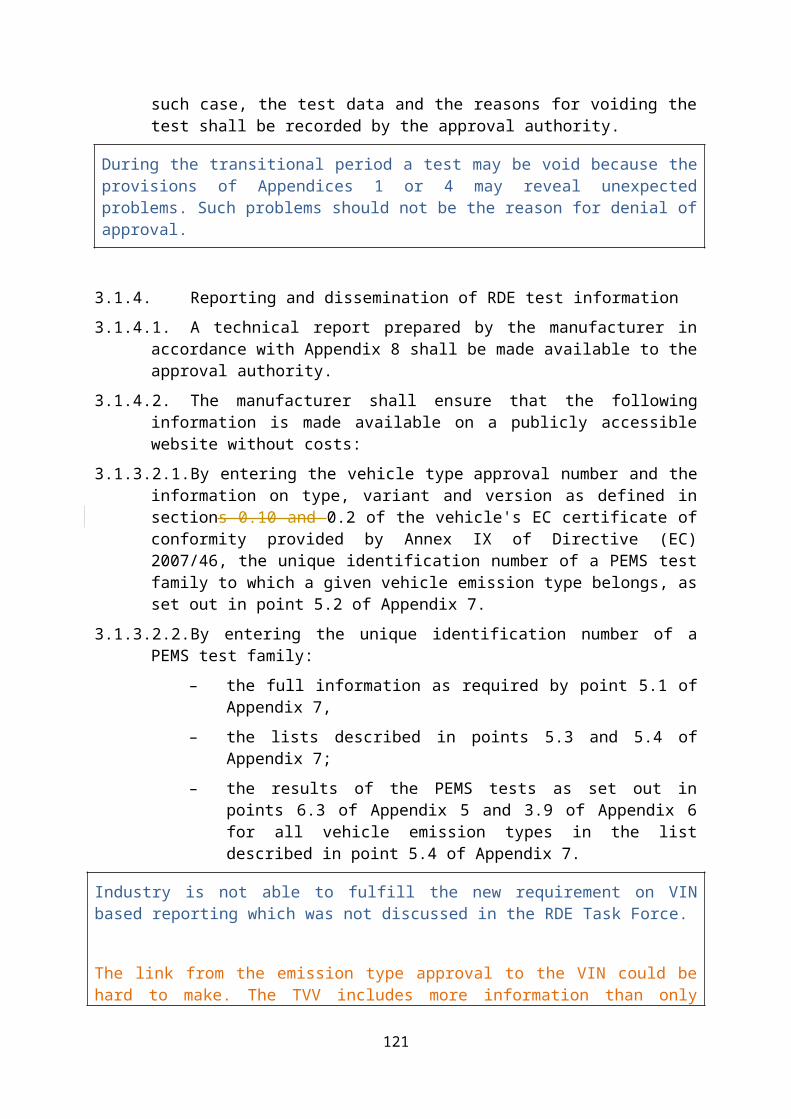
[3.1.3.] From three years after the dates specified in paragraphs 4 and 5 of Article 10 of Regulation (EC) No 715/2007, iIf the approval authority is not satisfied with the data quality check and validation results of a PEMS test conducted according to Appendices 1 and 4, the approval authority may consider the test to be void. In such case, the test data and the reasons for voiding the test shall be recorded by the approval authority.
During the transitional period a test may be void because the provisions of Appendices 1 or 4 may reveal unexpected problems. Such problems should not be the reason for denial of approval.
3.1.3.[3.1.4.] Reporting and dissemination of RDE test information
3.1.3.1.[3.1.4.1.] A technical report prepared by the manufacturer in accordance with Appendix 8 shall be made available to the approval authority.
3.1.3.2.[3.1.4.2.] The manufacturer shall ensure that the following information is made available on a publicly accessible website without costs:
118
3.1.3.2.1.By entering the vehicle type approval number and the information on type, variant and version as defined in sections 0.10 and 0.2 of the vehicle's EC certificate of conformity provided by Annex IX of Directive (EC) 2007/46, the unique identification number of a PEMS test family to which a given vehicle emission type belongs, as set out in point 5.2 of Appendix 7.
3.1.3.2.2.By entering the unique identification number of a PEMS test family:
– the full information as required by point 5.1 of Appendix 7,
– the lists described in points 5.3 and 5.4 of Appendix 7;
– the results of the PEMS tests as set out in points 6.3 of Appendix 5 and 3.9 of Appendix 6 for all vehicle emission types in the list described in point 5.4 of Appendix 7.
Industry is not able to fulfill the new requirement on VIN based reporting which was not discussed in the RDE Task Force.
The link from the emission type approval to the VIN could be hard to make. The TVV includes more information than only emission type, so it is not known at the moment of the emission certificate delivery.
The VIN (section 0.10) is impossible to be known at the moment of the WVTA, and for the TAA it is difficult to have the information when the vehicle is sold.
So the OEM website will be checked after the WVTA.
Moreover, when the emissions certificate is signed by another TAA, than the TAA of the WVTA, which TAA is in charge of the points above?
3.1.3.3.[3.1.4.3.] Upon request, without costs and within 30 days, the manufacturer shall make available the technical report referred to in point 3.1.3.1 to any interested party.
3.1.3.4.[3.1.4.4.] Upon request, the type approval authority shall make available the information listed under points 3.1.3.1 and 3.1.3.2 within 30 days of receiving the request. The type approval authority may charge a reasonable and proportionate fee, which does not discourage an inquirer with a justified interest from requesting the respective information or exceed the internal costs of the authority for making the requested information available.
4. GENERAL REQUIRMENTS
4.1. The RDE performance shall be demonstrated by testing vehicles on the road operated over their normal driving patterns, conditions and payloads. The RDE test shall be representative for vehicles operated on their real driving routes, with their normal load.
4.2. The manufacturer shall demonstrate to the approval authority that the chosen vehicle, driving patterns, conditions and payloads are representative for the vehicle family. The payload and altitude requirements, as specified in points 5.1 and 5.2,
119

shall be used ex-ante to determine whether the conditions are acceptable for RDE testing.
4.3. The approval authority shall propose a test trip in urban, rural and motorway environments meeting the requirements of point 6. For the purpose of trip selection, the definition of urban, rural and motorway operation shall be based on a topographic map.
4.4. If for a vehicle the collection of ECU data influences the vehicle's emissions or performance the entire PEMS test family to which the vehicle belongs as defined in Appendix 7 shall be considered as non-compliant. Such functionality shall be considered as a 'defeat device' as defined in Article 3(10) of Regulation (EC) 715/2007.
5. BOUNDARY CONDITIONS
5.1. Vehicle payload and test mass
5.1.1. The vehicle's basic payload shall comprise the driver, a witness of the test (if applicable) and the test equipment, including the mounting and the power supply devices.
5.1.2. For the purpose of testing some artificial payload may be added as long as the total mass of the basic and artificial payload does not exceed 90% of the sum of the “mass of the passengers” and the “pay-mass” defined in points 19 and 21 of Article 2 of Commission Regulation (EU) No 1230/2012(*).
“As outlined by the following equations.❑❑❑❑❑
❑❑❑❑❑❑❑❑
❑❑
❑❑❑❑❑
❑❑❑❑❑❑
❑❑
❑❑❑❑❑❑❑❑❑
❑❑❑❑❑❑
❑❑
❑❑❑❑❑❑
Comment: Clarification
_________
(*) Commission Regulation (EU) No 1230/2012 of 12 December 2012 implementing Regulation (EC) No 661/2009 of the European Parliament and of the Council with regard to type-approval requirements for masses and dimensions of motor vehicles and their trailers and amending Directive 2007/46/EC of the European Parliament and of the Council (OJ L 353, 21.12.2012, p. 31).
5.2. Ambient conditions
120
5.2.1. The test shall be conducted under ambient conditions laid down in this section. The ambient conditions become “extended” when at least one of the temperature and altitude conditions is extended.
5.2.2. Moderate altitude conditions: Altitude lower or equal to 700 meters above sea level.
If the trip altitude is lower than 0 metres above sea level, then is the test voided? The Netherlands has areas below sea level (~ 7m)
5.2.3. Extended altitude conditions: Altitude higher than 700 meters above sea level and lower or equal to 1300 meters above sea level.
A strong aspect of the RDE requirements is that no restrictions are introduced to limit the window of wind speeds, air pressure, humidity, road inclines and surfaces (provided that the road is paved).
5.2.4. Moderate temperature conditions: Greater than or equal to 273K (0°C) and lower than or equal to 303K (30°C)
In point 5.2.4 of AnneXIIIA, 273K is equal to 0 °C. Should PP judge the ambient conditions at 273K or 273.15K? And also should PP convert exhaust volume flow rate to exhaust mass flow rate by using 273K or 273.15K? PP use 273.15K to judge trip composition but use 273.15K to convert exhaust mass flow rate.
5.2.5. Extended temperature conditions: Greater than or equal to 266 K (-7°C) and lower than 273 K (0°C) or greater than 303 K (30°C) and lower than or equal to 308 K (35°C)
5.2.6. By way of derogation from the provisions of points 5.2.4 and 5.2.5 the lower temperature for moderate conditions shall be greater or equal to 276K (3°C) and the lower temperature for extended conditions shall be greater or equal to 271K (-2°C) between the start of the application of binding NTE emission limits as defined in section 2.1 and until five years after the dates given in paragraphs 4 and 5 of Article 10, of Regulation (EC) No 715/2007.
For the situation in The Netherlands the temperature boundaries can be assessed as being adequate but not strict, with no room to narrow the window.
5.3. Not applicable.
5.4. Dynamic conditions
The dynamic conditions encompass the effect of road grade, head wind and driving dynamics (accelerations, decelerations) and auxiliary systems upon energy consumption and emissions of the test vehicle. The verification of the normality of dynamic conditions shall be done after the test is completed, using the recorded PEMS data. This verification shall be conducted in 2 steps:
121

5.4.1. The overall excess or insufficiency of driving dynamics during the trip shall be checked using the methods described in Appendix 7a to this Annex.
5.4.2. If the trip results as valid following the verifications according to point 5.4.1, the methods for verifying the normality of the test conditions as laid down in Appendices 5 and 6 to this Annex must be applied. Each method includes a reference for test conditions, ranges around the reference and the minimum coverage requirements to achieve a valid test.
“Compliance of the software tool with the provisions laid down in Appendix 5 or 6 shall either be certified by the tool provider or testified by the type approval authority.”
The software provider should prove compliance with the methods laid down in Appendix 5 or 6 by an approval authority certificate. Compliance of non-certified software tools with the provisions of Appendix 5 or 6 should be testified by the type approval authority conducting or supervising the RDE tests.
5.5. Vehicle condition and operation
For PHEV, I could not find anything regarding the SoC of the battery. Shouldn't it be included as amendment of section 5.5 (vehicle condition and operation?)
5.5.1. Auxiliary systems
The air conditioning system or other auxiliary devices shall be operated in a way which corresponds to their possible typical use by a consumer at real driving on the road. “When using the air conditioning system, heating systems (e.g. seat heating or auxiliary heaters) shall be switched off and the vehicle windows shall be closed. When using heating systems (e.g. seat heating or auxiliary heaters), the air conditioning system shall be switched off.”
“possible” would include also an intentionally unreasonable use of such a device. To avoid unreasonable use of heaters and coolers at the same time.
“The vehicle windows shall be closed. The use of trailers or roof boxes and the transport of bicycles on their carriers is not permitted.”
To avoid drag variations caused by such equipment.
5.5.2. Vehicles equipped with periodically regenerating systems
5.5.2.1. “Periodically regenerating systems” shall be understood according to the definition in Article 2(6).
5.5.2.2. If periodic regeneration occurs during a test, the test may be voided and repeated once at the request of the manufacturer.
122
5.5.2.3. The manufacturer may ensure the completion of the regeneration and precondition the vehicle appropriately prior to the second test.
5.5.2.4. If regeneration occurs during the repetition of the RDE test, pollutants emitted during the repeated test shall be included in the emissions evaluation.
6. TRIP REQUIREMENTS
This moment in time, with no RDE-compliant cars available, the risk of increased real-world emissions due to trip recognition and/or trip optimization. Future testing programmes should keep the developments under review. Fundamentally, RDE testing should be unrestricted, except for some basic average properties and boundaries.
6.1. The shares of urban, rural and motorway driving, classified by instantaneous speed as described in points 6.3 to 6.5, shall be expressed as a percentage of the total trip distance.
6.2. The trip sequence shall consist of urban driving followed by rural and motorway driving according to the shares specified in point 6.6. The urban, rural and motorway operation shall be run continuously. Rural operation may be interrupted by short periods of urban operation when driving through urban areas. Motorway operation may be interrupted by short periods of urban or rural operation, e.g., when passing toll stations or sections of road work. If another testing order is justified for practical reasons, the order of urban, rural and motorway operation may be altered, after obtaining approval from the approval authority.
6.3. Urban operation is characterised by vehicle speeds lower than or equal to 60 km/h.
“For M2 and N2 vehicles the urban operation is characterised by vehicle speeds between 0 and 50 km/h.”
Pursuant to Article 2 of Regulation (EC) No 715/2007, the provisions of Appendix IIIA of Regulation (EC) No 692/2008 apply for vehicles of category M2 and N2 with a reference mass up to 2610 kg. Pursuant to Articles 2 and 3 of Directive 92/6/EEC, the maximum speed of category M2 and N2 vehicles has to be limited to 100 km/h and 90 km/h, respectively, by means of speed limiting devices.
Currently is technically impossible to conduct a valid RDE trip for category M2 and N2 vehicles under the RDE regulation. There has to be a differentiation of urban operation between M1, N1 and M2, N2 vehicles to adopt the speed requirements of heavy duty regulation 595/2009 for M2 and N2 vehicles.
6.4. Rural operation is characterised by vehicle speeds higher than 60 and lower than or equal to 90 km/h. “For M2 and N2 vehicles the rural operation is characterised by vehicle speeds higher than 50 and lower than or equal to 75 km/h.”
Pursuant to Article 2 of Regulation (EC) No 715/2007, the provisions of Appendix IIIA of Regulation (EC) No 692/2008 apply for vehicles of category M2 and N2 with
123

a reference mass up to 2610 kg.
Pursuant to Articles 2 and 3 of Directive 92/6/EEC, the maximum speed of category M2 and N2 vehicles has to be limited to 100 km/h and 90 km/h, respectively, by means of speed limiting devices.
Currently is technically impossible to conduct a valid RDE trip for category M2 and N2 vehicles under the RDE regulation.
There has to be a differentiation of urban operation between M1, N1 and M2, N2 vehicles to adopt the speed requirements of heavy duty regulation 595/2009 for M2 and N2 vehicles.
6.5. Motorway operation is characterised by speeds above 90 km/h. “For M2 and N2 vehicles motorway operation is characterised by vehicle speeds above 75 km/h.”
Pursuant to Article 2 of Regulation (EC) No 715/2007, the provisions of Appendix IIIA of Regulation (EC) No 692/2008 apply for vehicles of category M2 and N2 with a reference mass up to 2610 kg.
Pursuant to Articles 2 and 3 of Directive 92/6/EEC, the maximum speed of category M2 and N2 vehicles has to be limited to 100 km/h and 90 km/h, respectively, by means of speed limiting devices.
Currently is technically impossible to conduct a valid RDE trip for category M2 and N2 vehicles under the RDE regulation.
There has to be a differentiation of urban operation between M1, N1 and M2, N2 vehicles to adopt the speed requirements of heavy duty regulation 595/2009 for M2 and N2 vehicles.
6.6. The trip shall consist of approximately 34% per cent urban, 33% per cent rural and 33% per cent motorway driving classified by speed as described in points 6.3 to 6.5 above. “Approximately” shall mean the interval of ±10 per cent points around the stated percentages. The urban driving shall however never be less than 29% of the total trip distance.
From our understanding, urban 34 ±10%, rural 33±10%, motorway 33±10%; 29% ≦ urban ⇒ 29%≦urban < (≦)44% Then, does urban parts include equal to 44%? For safety, we would say > 29%(e.g 29.01) and < 44 % (e.g.43.99) In the end, this will be based on rounding in the calculations.
6.7. The vehicle velocity shall normally not exceed 145 km/h. This maximum speed may be exceeded by a tolerance of 15 km/h for not more than 3% of the time duration of the motorway driving. Local speed limits remain in force during a PEMS test, notwithstanding other legal consequences. Violations of local speed limits per se do not invalidate the results of a PEMS test.
6.8. The average speed (including stops) of the urban driving part of the trip should be between 15 and 40 km/h. Stop periods, defined as vehicle speed of less than 1 km/h,
124

shall account for 6 to 30% of the time duration of urban operation. Urban operation shall contain several stop periods of 10s or longer. If a stop period lasts more the 180 s, the emission events during the 180 s following such an excessively long stop period shall be excluded from the emissions evaluation.
Suggestion on previous text version: “If a stop period lasts more the 180 s, the pollutant emission data during the 180 s following such an excessively long stop period shall be set to zero for the emissions evaluation.”
Argument: Clarification.
The risk of high local emissions due to occasionally long stops during urban driving can be removed by deletion of the requirement that 3 minutes of measurement data following a long stop will be excluded from the evaluation. Preferably, additionally the maximum duration of a stop is extended.
In order to cover a wider range of urban driving throughout Europe, in particular stop and go traffic frequently observed in densely populated areas with high traffic density, it could be considered to lower the limit of the average speed during urban driving of RDE trips. In any case there is no room to increase the current limit of 15 km/h as proposed by experts from the car industry.
I ask this question to know how manufacturers do the RDE test. Is the purpose of this stop periods to know the behavier of the stop-and-start function of vehicle? I am just wondering the reason, because this stop periods will exculde in post data processing.
6.9. The speed range of the motorway driving shall properly cover a range between 90 and at least 110 km/h. The vehicle's velocity shall be above 100 km/h for at least 5 minutes.
“For vehicles of categories M1 and N1 as defined in Annex II to Directive 70/156/EEC the speed range of the motorway driving shall properly cover a range between 90 and at least 110 km/h. The vehicle's velocity shall be above 100 km/h for at least 5 minutes.
For vehicles of categories M2 and N2 as defined in Annex II to Directive 70/156/EEC the speed range of the motorway driving shall properly cover a range between 75 km/h and the legal speed limit.”
Pursuant to Articles 2 and 3 of Directive 92/6/EEC, the maximum speed of category M2 and N2 vehicles has to be limited to 100 km/h or 90 km/h, respectively, by means of speed limiting devices. Additionally legal speed limits may apply. Currently is technically impossible to conduct a valid RDE trip for category M2 and N2 vehicles under the RDE regulation.
There has to be a differentiation of urban operation between M1, N1 and M2, N2 vehicles to adopt the speed requirements of heavy duty regulation 595/2009 for M2 and N2 vehicles.
6.10. The trip duration shall be between 90 and 120 minutes.
125

6.11. The start and the end point shall not differ in their elevation above sea level by more than 100 m. In addition, the proportional cumulative positive altitude gain shall be less than 1200 m/100km) and be determined according to Appendix 7b.
Do the 1200m/100 km apply also to the entireurban driving? Why not 400 or 500 m? Choosing hilly urban driving could beproblematic.
6.12. The minimum distance of each, the urban, rural and motorway operation shall be 16 km.
7. OPERATIONAL REQUIREMENTS
7.1. The trip shall be selected in such a way that the testing is uninterrupted and the data continuously recorded to reach the minimum test duration defined in point 6.10.
7.2. Electrical power shall be supplied to the PEMS by an external power supply unit and not from a source that draws its energy either directly or indirectly from the engine of the test vehicle.
7.3. The installation of the PEMS equipment shall be done in a way to influence the vehicle emissions or performance or both to the minimum extent possible. Care should be exercised to minimize the mass of the installed equipment and potential aerodynamic modifications of the test vehicle. The vehicle payload shall be in accordance with point 5.1.
7.4. RDE tests shall be conducted on working days as defined for the Union in Council Regulation (EEC, Euratom) No 1182/71(*)
______
(*) Regulation (EEC, Euratom) No 1182/71 of the Council of 3 June 1971 determining the rules applicable to periods, dates and time limits (OJ L 124, 8.6.1971, p. 1).
Only working days are defined by 1182/71 and day off of the MS, does it mean that no more "working hours" are requested? Test could be driven by night?
7.5. RDE tests shall be conducted on paved roads and streets (e.g. off road operation is not permitted).
7.6. Prolonged idling shall be avoided after the first ignition of the combustion engine at the beginning of the emissions test. If the engine stalls during the test, it may be restarted, but the sampling shall not be interrupted.
8. LUBRICATING OIL, FUEL AND REAGENT
8.1. The fuel, lubricant and reagent (if applicable) used for RDE testing shall be within the specifications issued by the manufacturer for vehicle operation by the customer.
126

8.2. Samples of fuel, lubricant and reagent (if applicable) shall be taken and kept for at least 1 year.
“In the case of a PEMS test performed by an independent organisation, sSamples of fuel, lubricant and reagent (if applicable) shall be taken and kept for at least 1 year at a temperature between 10°C and 20°C and protected from light.”
Argument: OEMs and TAA can bring the specifications of the fuel, oil and reagent they use – 3rd parties cannot.
Where? Kept by whom? Under which conditions (e.g. temperature/humidity)?
At the time being for monitoring we request the analysis of the fluids.
9. EMISSIONS AND TRIP EVALUATION
9.1. The test shall be conducted in accordance with Appendix 1 of this Annex.
9.2. The trip shall fulfil the requirements set out in points 4 to 8.
9.3. It shall not be permitted to combine data of different trips or to modify or remove data from a trip with exception of provisions for long stops as described in 6.8.
9.4. After establishing the validity of a trip according to Point 9.2 emission results shall be calculated using the methods laid down in Appendices 5 and 6 of this Annex.
9.5. If during a particular time interval the ambient conditions are extended in accordance with point 5.2, the pollutant emissions during this particular time interval, calculated according to Appendix 4, shall be divided by a value of 1,6 before being evaluated for compliance with the requirements of this Annex. This provision does not apply to carbon dioxide emissions.
Ensure consistent use of comma and point as decimal separator.
9.6. The cold start is defined in accordance with point 4 of Appendix 4 of this Annex. Until specific requirements for emissions at cold start are applied, the latter shall be recorded but excluded from the emissions evaluation.
127

Appendix 1
Test procedure for vehicle emissions testing with a Portable Emissions Measurement System (PEMS)
1. INTRODUCTION
This Appendix describes the test procedure to determine exhaust emissions from light passenger and commercial vehicles using a Portable Emissions Measurement System.
2. SYMBOLS, PARAMETERS AND UNITS
≤ - smaller or equal
# - number
#/m3 - number per cubic metre
% - per cent
oC - degree centigrade
g - gramme
g/s - gramme per second
h - hour
Hz - hertz
K - kelvin
kg - kilogramme
kg/s - kilogramme per second
km - kilometre
km/h - kilometre per hour
kPa - kilopascal
kPa/min - kilopascal per minute
128

l - litre
l/min - litre per minute
m - metre
m3 - cubic-metre
mg - milligram
min - minute
pe - evacuated pressure [kPa]
qvs - volume flow rate of the system [l/min]
ppm - parts per million
ppmC1 - parts per million carbon equivalent
rpm - revolutions per minute
s - second
Vs - system volume [l]
3. GENERAL REQUIREMENTS
3.1. PEMSThe test shall be carried out with a PEMS, composed of components specified in points 3.1.1 to 3.1.5. If applicable, a connection with the vehicle ECU may be established to determine relevant engine and vehicle parameters as specified in point 3.2.
3.1.1. Analysers to determine the concentration of pollutants in the exhaust gas.
3.1.2. One or multiple instruments or sensors to measure or determine the exhaust mass flow.
3.1.3. A Global Positioning System to determine the position, altitude and, speed of the vehicle.
129

3.1.4. If applicable, sensors and other appliances being not part of the vehicle, e.g., to measure ambient temperature, relative humidity, air pressure, and vehicle speed.
3.1.5. An energy source independent of the vehicle to power the PEMS.
3.2. Test parametersTest parameters as specified in Table 1 of this Appendix shall be measured, recorded at a constant frequency of 1.0 Hz or higher and reported according to the requirements of Appendix 8. If ECU parameters are obtainedavailable, these should be made availablerequested at a substantially higherthe same frequency thanas the parameters recorded by PEMS. The PEMS analysers, flow-measuring instruments and sensors shall comply with the requirements laid down in Appendices 2 and 3 of this Annex.
ACEA recommends to use a fixed frequency of 1 Hz in order to minimize interference with the provisions of the other Appendices (particularly Appendix 6) and to facilitate post-processing of the data.Table 1 contains several values, the data source of which is marked as “ECU”. However the transmission of most of these values is not (or only optional) requested by the OBD regulation. Thus it cannot be anticipated that these values are available from the ECU.The available data rate depends on the type and amount of requested data and on the number of answering control units. A data rate “substantially higher“ than 1Hz may not be possible.
Table 1
Test parameters
Parameter Recommended unit Source(8)
THC concentration(1,4) ppm Analyser
CH4 concentration(1,4) ppm Analyser
NMHC concentration(1,4) ppm Analyser(6)
CO concentration(1,4) ppm Analyser
CO2 concentration(1) ppm Analyser
NOX concentration(1,4) ppm Analyser(7)
PN concentration(4) #/m3 Analyser
Exhaust mass flow rate kg/s EFM, any methods described in point 7 of Appendix 2
Ambient humidity % Sensor
130

Ambient temperature K Sensor
Ambient pressure kPa Sensor
Vehicle speed km/h Sensor, GPS, or ECU(3)
Vehicle latitude Degree GPS
Vehicle longitude Degree GPS
Vehicle altitude(5,9) M GPS or Sensor
Exhaust gas temperature(5) K Sensor
Engine coolant temperature(5) K Sensor or ECU
Engine speed(5) rpm Sensor or ECU
Engine torque(5) Nm Sensor or ECU
Torque at driven axle(5) Nm Rim torque meter
Pedal position(5) % Sensor or ECU
Engine fuel flow(2) g/s Sensor or ECU
Engine intake air flow(2) g/s Sensor or ECU
Fault status(5) - ECU
Intake air flow temperature K Sensor or ECU
Regeneration status(5) - ECU
Engine oil temperature(5) K Sensor or ECU
Actual gear(5) # ECU
Desired gear (e.g. gear shift indicator)(5)
# ECU
Other vehicle data(5) unspecified ECU
Notes:
(1) to be measured on a wet basis or to be corrected as described in point 8.1 of Appendix 4
(2) to be determined only if indirect methods are used to calculate exhaust mass flow rate as described in paragraphs 10.2 and 10.3 of Appendix 4
(3) method to be chosen according to point 4.7
(4) parameter only mandatory if measurement required by Annex IIIA, section 2.1
131

(5) to be determined only if necessary to verify the vehicle status and operating conditions
(6) may be calculated from THC and CH4 concentrations according to point 9.2 of Appendix 4
(7) may be calculated from measured NO and NO2 concentrations
(8) Multiple parameter sources may be used.
(9) The preferable source is the ambient pressure sensor.
In table 2, the recommended units are 'ppm' for 'THC concentration', 'CH4 concentration' and 'NMHC concentrtion'. OBS use the 'ppmC' for these gas concentration. If it is possible, please unify the unit in Euro6 to avoid confusing. (These compounds will be standard units - ppmC)
3.3. Preparation of the vehicleThe preparation of the vehicle shall include a general verification of the correct technical functioning of the test vehicle.
3.4. Installation of PEMS
3.4.1. General
The installation of the PEMS shall follow the instructions of the PEMS manufacturer and the local health and safety regulations. The PEMS should be installed as to minimize during the test electromagnetic interferences as well as exposure to shocks, vibration, dust and variability in temperature. The installation and operation of the PEMS shall be leak-tight and minimize heat loss. The installation and operation of PEMS shall not change the nature of the exhaust gas nor unduly increase the length of the tailpipe. To avoid the generation of particles, connectors shall be thermally stable at the exhaust gas temperatures expected during the test. It is recommended to avoid the use of a material which may emit volatile components to connect the vehicle exhaust outlet and the connecting tube. Elastomer connectors, if used, shall have a minimum exposure to the exhaust gas to avoid artefacts at high engine load.
3.4.2. Permissible backpressure
The installation and operation of the PEMS shall not unduly increase the static pressure at the exhaust outlet. If technically feasible, any extension to facilitate the sampling or connection with the exhaust mass flow meter shall have an equivalent, or larger, cross sectional area than the exhaust pipe.
3.4.3. Exhaust mass flow meter
Whenever used, the exhaust mass flow meter shall be attached to the vehicle's tailpipe(s) according to the recommendations of the EFM manufacturer. The measurement range of the EFM shall match the range of the exhaust mass flow rate expected during the test. The installation of the EFM and any exhaust pipe adaptors or junctions shall not adversely affect the operation of the engine or exhaust
132

after-treatment system. A minimum of four pipe diameters or 150 mm of straight tubing, whichever is larger, shall be placed at either side of the flow-sensing element. When testing a multi-cylinder engine with a branched exhaust manifold, it is recommended to combine the manifolds upstream of the exhaust mass flow meter and to increase the cross section of the piping appropriately as to minimize backpressure in the exhaust. If this is not feasible, exhaust flow measurements with several exhaust mass flow meters shall be considered. The wide variety of exhaust pipe configurations, dimensions and exhaust mass flow rates may require compromises, guided by good engineering judgement, when selecting and installing the EFM(s). If measurement accuracy requires, it is permissible to install an EFM with a diameter smaller than that of the exhaust outlet or the total cross-sectional area of multiple outlets, providing it does not adversely affect the operation or the exhaust after-treatment as specified in point 3.4.2.
Are there any thresholds or parameters to know the effect? OBS has 5 types of pitot tube size as a line up to measure the exhaust mass flow rate. Therefore car manufacturers can select from these. This is covered in the text by two statements.EFM should be selected by the exhaust flow rate of the vehicle under RDE test conditions.And the statement: The installation of the EFM and any exhaust pipe adaptors or junctions shall not adversely affect the operation of the engine or exhaust after-treatment system.
The basis of the decision for the EFM is "good engineering judgment" based on the vehicle design. For example, back pressure might affect the Low Pressure EGR so it is especially important not to use too small a diameter flow tube in this case.
3.4.4. Global Positioning System (GPS)
The GPS antenna should be mounted, e.g. at the highest possible location, as to ensure good reception of the satellite signal. The mounted GPS antenna shall interfere as little as possible with the vehicle operation.
3.4.5. Connection with the Engine Control Unit (ECU)
If desired, relevant vehicle and engine parameters listed in Table 1 can be recorded by using a data logger connected with the ECU or the vehicle network through standards, such as ISO 15031-5 or SAE J1979, OBD-II, EOBD or WWH-OBD. If applicable, manufacturers shall disclose labels to allow the identification of required parameters.
3.4.6. Sensors and auxiliary equipment
Vehicle speed sensors, temperature sensors, coolant thermocouples or any other measurement device not part of the vehicle shall be installed to measure the parameter under consideration in a representative, reliable and accurate manner without unduly interfering with the vehicle operation and the functioning of other analysers, flow-measuring instruments, sensors and signals. Sensors and auxiliary equipment shall be powered independently of the vehicle. It is permitted to power any safety-related illumination of fixtures and installations of PEMS components outside of the vehicle’s cabin by the vehicle’s battery.
133

3.5. Emissions samplingEmissions sampling shall be representative and conducted at locations of well-mixed exhaust where the influence of ambient air downstream of the sampling point is minimal. If applicable, emissions shall be sampled downstream of the exhaust mass flow meter, respecting a distance of at least 150 mm to the flow sensing element. The sampling probes shall be fitted at least 200 mm or three times the inner diameter of the exhaust pipe, whichever is larger, upstream of the point at which the exhaust exits the PEMS sampling installation into the environment. If the PEMS feeds back a flow to the tail pipe, this shall occur downstream of the sampling probe in a manner that does not affect during engine operation the nature of the exhaust gas at the sampling point(s). If the length of the sampling line is changed, the system transport times shall be verified and if necessary corrected.
If the engine is equipped with an exhaust after-treatment system, the exhaust sample shall be taken downstream of the exhaust after-treatment system. When testing a vehicle with a multi-cylinder engine and branched exhaust manifold, the inlet of the sampling probe shall be located sufficiently far downstream so as to ensure that the sample is representative of the average exhaust emissions of all cylinders. In multi-cylinder engines, having distinct groups of manifolds, such as in a "V" engine configuration, the manifolds shall be combined upstream of the sampling probe. If this is technically not feasible, multi-point sampling at locations of well-mixed exhaust free of ambient air shall be considered. In this case, the number and location of sampling probes shall match as far as possible those of the exhaust mass flow meters. In case of unequal exhaust flows, proportional sampling or sampling with multiple analysers shall be considered.
If particles are measured, the exhaust shall be sampled from the centre of the exhaust stream. If several probes are used for emissions sampling, the particle sampling probe shall be placed upstream of the other sampling probes.
If hydrocarbons are measured, the sampling line shall be heated to 463 ± 10 K (190 ± 10 °C). For the measurement of other gaseous components with or without cooler, the sampling line shall be kept at a minimum of 333 K (60°C) to avoid condensation and to ensure appropriate penetration efficiencies of the various gases. For low pressure sampling systems, the temperature can be lowered corresponding to the pressure decrease provided that the sampling system ensures a penetration efficiency of 95% for all regulated gaseous pollutants. If particles are sampled, the sampling line from the raw exhaust sample point shall be heated to a minimum of 373 K (100 °C). The residence time of the sample in the particle sampling line shall be less than 3 s until reaching first dilution or the particle counter.
134

4. PRE-TEST PROCEDURES
4.1. PEMS leak checkAfter the installation of the PEMS is completed, a leak check shall be performed at least once for each PEMS-vehicle installation as prescribed by the PEMS manufacturer or as follows. The probe shall be disconnected from the exhaust system and the end plugged. The analyser pump shall be switched on. After an initial stabilization period all flow meters shall read approximately zero in the absence of a leak. Else, the sampling lines shall be checked and the fault be corrected.
The leakage rate on the vacuum side shall not exceed 0.5 per cent of the in-use flow rate for the portion of the system being checked. The analyser flows and bypass flows may be used to estimate the in-use flow rate.
Alternatively, the system may be evacuated to a pressure of at least 20 kPa vacuum (80 kPa absolute). After an initial stabilization period the pressure increase p (kPa/min) in the system shall not exceed:
Alternatively, a concentration step change at the beginning of the sampling line shall be introduced by switching from zero to span gas while maintaining the same pressure conditions as under normal system operation. If for a correctly calibrated analyser after an adequate period of time the reading is ≤99 per cent compared to the introduced concentration, the leakage problem shall be corrected.
4.2. Starting and stabilizing the PEMSThe PEMS shall be switched on, warmed up and stabilized according to the specifications of the PEMS manufacturer until, e.g., pressures, temperatures and flows have reached their operating set points.
4.3. Preparing the sampling systemThe sampling system, consisting of the sampling probe, sampling lines and the analysers, shall be prepared for testing by following the instruction of the PEMS manufacturer. It shall be ensured that the sampling system is clean and free of moisture condensation.
135

4.4. Preparing the Exhaust mass Flow Meter (EFM)If used for measuring the exhaust mass flow, the EFM shall be purged and prepared for operation in accordance with the specifications of the EFM manufacturer. This procedure shall, if applicable, remove condensation and deposits from the lines and the associated measurement ports.
4.5. Checking and calibrating the analysers for measuring gaseous emissionsZero and span calibration adjustments of the analysers shall be performed using calibration gases that meet the requirements of point 5 of Appendix 2. The calibration gases shall be chosen to match the range of pollutant concentrations expected during the RDE test. To minimize analyser drift, one should conduct the zero and span calibration of analysers at an ambient temperature that resembles, as closely as possible, the temperature experienced by the test equipment during the trip.
4.6. Checking the analyser for measuring particle emissionsThe zero level of the analyser shall be recorded by sampling HEPA filtered ambient air. The signal shall be recorded at a constant frequency of at least 1.0 Hz over a period of 2 min and averaged; the permissible concentration value shall be determined once suitable measurement equipment becomes available.
ACEA recommends to use a fixed frequency of 1 Hz in order to minimize interference with the provisions of the other Appendices (particularly Appendix 6) and to facilitate post-processing of the data.
Proposal to allow auto-zeroing of PN analyser: “Alternatively, the user can follow the leak test procedure defined by the PEMS manufacturer providing that it fully meets the intention of being able to demonstrate the particle number measurement device is operating in accordance with the required performance specifications”.
4.7. Determining vehicle speedVehicle speed shall be determined by at least one of the following methods:
(a) a GPS; if vehicle speed is determined by a GPS, the total trip distance shall be checked against the measurements of another method according to point 7 of Appendix 4.
(b) a sensor (e.g., optical or micro-wave sensor); if vehicle speed is determined by a sensor, the speed measurements shall comply with the requirements of point 8 of Appendix 2, or alternatively, the total trip distance determined by the sensor shall be compared with a reference distance obtained from a digital road network or topographic map. The total trip distance determined by the sensor shall deviate by no more than 4% from the reference distance.
(c) the ECU; if vehicle speed is determined by the ECU, the total trip distance shall be validated according to point 3 of Appendix 3 and the ECU speed signal adjusted, if necessary to fulfil the requirements of point 3.3 of Appendix 3. Alternatively, the total trip distance as determined by the ECU can be
136

compared with a reference distance obtained from a digital road network or topographic map. The total trip distance determined by the ECU shall deviate by no more than 4% from the reference.
4.8. Check of PEMS set upThe correctness of connections with all sensors and, if applicable, the ECU shall be verified. If engine parameters are retrieved, it shall be ensured that the ECU reports values correctly (e.g., zero engine speed [rpm] while the combustion engine is in key-on-engine-off status). The PEMS shall function free of warning signals and error indication.
If errors and warning signals occur for PN PEMS, these should be recorded.
5. EMISSIONS TEST
5.1. Test startSampling, measurement and recording of parameters shall begin prior to the start of the engine. To facilitate time alignment, it is recommended to record the parameters that are subject to time alignment either by a single data recording device or with a synchronised time stamp. Before and directly after engine start, it shall be confirmed that all necessary parameters are recorded by the data logger.
5.2. TestSampling, measurement and recording of parameters shall continue throughout the on-road test of the vehicle. The engine may be stopped and started, but emissions sampling and parameter recording shall continue. Any warning signals, suggesting malfunctioning of the PEMS, shall be documented and verified. Parameter recording shall reach a data completeness of higher than 99%. Measurement and data recording may be interrupted for less than 1% of the total trip duration but for no more than a consecutive period of 30 s solely in the case of unintended signal loss or for the purpose of PEMS system maintenance. Interruptions may be recorded directly by the PEMS. It is not permissible to introduce interruptions in the recorded parameter via the pre-processing, exchange or post-processing of data. If conducted, auto zeroing shall be performed against a traceable zero standard similar to the one used to zero the analyser. If necessary it is strongly recommended to initiate PEMS system maintenance during periods of zero vehicle speed.
5.3. Test endThe end of the test is reached when the vehicle has completed the trip and the combustion engine is switched off. Excessive idling of the engine after the completion of the trip shall be avoided. The data recording shall continue until the response time of the sampling systems has elapsed.
137

6. POST-TEST PROCEDURE
6.1. Checking the analysers for measuring gaseous emissionsThe zero and span of the analysers of gaseous components shall be checked by using calibration gases identical to the ones applied under point 4.5 to evaluate the analyser's zero and response drift compared to the pre-test calibration. It is permissible to zero the analyser prior to verifying the span drift, if the zero drift was determined to be within the permissible range. The post-test drift check shall be completed as soon as possible after the test and before the PEMS, or individual analysers or sensors, are turned off or have switched into a non-operating mode. The difference between the pre-test and post-test results shall comply with the requirements specified in Table 2.
Table 2
Permissible analyser drift over a PEMS testPollutant Zero response drift Span response drift (1)
CO2 ≤2000 ppm per test ≤2% of reading or ≤2000 ppm per test, whichever is larger
CO ≤75 ppm per test ≤2% of reading or ≤75 ppm per test, whichever is larger
NO2 ≤5 ppm per test ≤2% of reading or ≤5 ppm per test, whichever is larger
NO/NOX ≤5 ppm per test ≤2% of reading or ≤5 ppm per test, whichever is larger
CH4 ≤10 ppmC1 per test ≤2% of reading or ≤10 ppmC1 per test, whichever is larger
THC ≤10 ppmC1 per test ≤2% of reading or ≤10 ppmC1 per test, whichever is larger
(1) If the zero drift is within the permissible range, it is permissible to zero the analyser prior to verifying the span drift.
If the difference between the pre-test and post-test results for the zero and span drift is higher than permitted, all test results shall be voided and the test repeated.
6.2. Checking the analyser for measuring particle emissionsThe zero level of the analyser shall be recorded by sampling HEPA filtered ambient air. The signal shall be recorded over a period of 2 min and averaged; the permissible final concentration shall be defined once suitable measurement equipment becomes available. If the difference between the
138

pre-test and post-test check is higher than permitted, all test results shall be voided and the test repeated.
6.3. Checking the on-road emission measurements
The used span gas concentration of the analysers as calibrated according to Appendix 1, paragraph 4.5 of this Annex shall cover The calibrated range of the analysers shall account at least for 90% of the concentration values obtained from 99% of the measurements of the valid parts of the emissions test. It is permissible that 1% of the total number of measurements used for evaluation exceeds the used span gas calibrated range of the analysers by up to a factor of two. If these requirements are not met, the test shall be voided.
Clarification.
Is our undersanding correct in below? SPAN Gas> 0.9×99th percentile and %measures values >= 2*spangas; This wording is ambiguous. Does "calibrated range" refer to analyser linearised range or the range relative to the span gas value used for the calibration?
To be honest, we do not understand this paragraph at the moment, our customers have trouble with this too. I would like to propose to rediscuss and clarify this. With the cold start coming in for “evaluation” I’m seeing this event more critical.
139

Appendix 2
Specifications and calibration of PEMS components and signals
1. INTRODUCTION
This appendix sets out the specifications and calibration of PEMS components and signals.
2. SYMBOLS, PARAMETERS AND UNITS > - larger than
≥ - larger than or equal to
% - per cent
≤ - smaller than or equal to
A - undiluted CO2 concentration [%]
a0 - y-axis intercept of the linear regression line
a1 - slope of the linear regression line
B - diluted CO2 concentration [%]
C - diluted NO concentration [ppm]
c - analyser response in the oxygen interference test
cFS,b - full scale HC concentration in step (b) [ppmC1]
cFS,d - full scale HC concentration in step (d) [ppmC1]
cHC(w/NMC) - HC concentration with CH4 or C2H6 flowing through the NMC
[ppmC1]
cHC(w/o NMC) - HC concentration with CH4 or C2H6 bypassing the
NMC [ppmC1]
cm,b - measured HC concentration in step (b) [ppmC1]
cm,d - measured HC concentration in step (d) [ppmC1]
cref,b - reference HC concentration in step (b) [ppmC1]
140

cref,d - reference HC concentration in step (d) [ppmC1]
oC - degree centigrade
D - undiluted NO concentration [ppm]
De - expected diluted NO concentration [ppm]
E - absolute operating pressure [kPa]
ECO2 - per cent CO2 quench
EE - ethane efficiency
EH2O - per cent water quench
EM - methane efficiency
EO2 - oxygen interference
F - water temperature [K]
G - saturation vapour pressure [kPa]
g - gram
gH2O/kg - gramme water per kilogram
h - hour
H - water vapour concentration [%]
Hm - maximum water vapour concentration [%]
Hz - hertz
K - kelvin
kg - kilogramme
km/h - kilometre per hour
kPa - kilopascal
max - maximum value
NOX,dry - moisture-corrected mean concentration of the stabilized NOX
recordings
NOX,m - mean concentration of the stabilized NOX recordings
NOX,ref - reference mean concentration of the stabilized NOX recordings
141

ppm - parts per million
ppmC1 - parts per million carbon equivalents
r2 - coefficient of determination
s - second
t0 - time point of gas flow switching [s]
t10 - time point of 10% response of the final reading
t50 - time point of 50% response of the final reading
t90 - time point of 90% response of the final reading
tbd - to be determined
x - independent variable or reference value
χmin - minimum value
y - dependent variable or measured value
3. LINEARITY VERIFICATION
3.1. GeneralThe linearity of analysers, flow-measuring instruments, sensors and signals, shall be traceable to international or national standards. Any sensors or signals that are not directly traceable, e.g., simplified flow-measuring instruments shall be calibrated alternatively against chassis dynamometer laboratory equipment that has been calibrated against international or national standards.
3.2. Linearity requirementsAll analysers, flow-measuring instruments, sensors and signals shall comply with the linearity requirements given in Table 1. If air flow, fuel flow, the air-to-fuel ratio or the exhaust mass flow rate is obtained from the ECU, the calculated exhaust mass flow rate shall meet the linearity requirements specified in Table 1.
Table 1
Linearity requirements of measurement parameters and systems
Measurement parameter/instrument
min (a1 - 1)+ a0
Slopea1
Standard errorSEE
Coefficient of determination
142

r2
Fuel flow rate(1) ≤1% max 0.98 - 1.02 ≤2% max ≥0.990
Air flow rate(1) ≤1% max 0.98 - 1.02 ≤2% max ≥0.990
Exhaust mass flow rate ≤2% max 0.97 - 1.03 ≤2% max ≥0.990
Gas analysers ≤0.5% max 0.99 - 1.01 ≤1% max ≥0.998
Torque(2) ≤1% max 0.98-1.02 ≤2% max ≥0.990
PN analysers(3) tbd tbd tbd tbd
(1) optional to determine exhaust mass flow
(2) optional parameter
(3) to be decided once equipment becomes available
About |xmin * (a1-1)+a0|, does 'max' means F.S. max? or Reading max? For OBS, reading max of linearity is almost same or over with F.S. so the result should be same but I would like to make it clearly. About Slope a1, does it include equal or not? Can JRC confirm generically whether this refers to detector full scale or maximum value during the RDE test
3.3. Frequency of linearity verificationThe linearity requirements according to point 3.2 shall be verified:
(a) for each analyser at least every three months or whenever a system repair or change is made that could influence the calibration;
(b) for other relevant instruments, such as exhaust mass flow meters and traceably calibrated sensors, whenever damage is observed, as required by internal audit procedures, by the instrument manufacturer or by ISO 9000 but no longer than one year before the actual test.
The linearity requirements according to point 3.2 for sensors or ECU signals that are not directly traceable shall be performed with a traceably calibrated measurement device on the chassis dynamometer once for each PEMS setup.
3.4. Procedure of linearity verification
3.4.1. General requirements
The relevant analysers, instruments and sensors shall be brought to their normal operating condition according to the recommendations of their manufacturer. The analysers, instruments and sensors shall be operated at their specified temperatures, pressures and flows.
143

3.4.2. General procedure
The linearity shall be verified for each normal operating range by executing the following steps:
(a) The analyser, flow-measuring instrument or sensor shall be set to zero by introducing a zero signal. For gas analysers, purified synthetic air or nitrogen shall be introduced to the analyser port via a gas path that is as direct and short as possible.
(b) The analyser, flow-measuring instrument or sensor shall be spanned by introducing a span signal. For gas analysers, an appropriate span gas shall be introduced to the analyser port via a gas path that is as direct and short as possible.
(c) The zero procedure of (a) shall be repeated.
(d) The linearity shall be verified by introducing at least 10, approximately equally spaced and valid, reference values (including zero). The reference values with respect to the concentration of components, the exhaust mass flow rate or any other relevant parameter shall be chosen to match the range of values expected during the emissions test. For measurements of exhaust mass flow, reference points below 5% of the maximum calibration value can be excluded from the linearity verification.
(e) For gas analysers, known gas concentrations in accordance with point 5 shall be introduced to the analyser port. Sufficient time for signal stabilisation shall be given.
[(f)] The values under evaluation and, if needed, the reference values shall be recorded at a constant frequency of at least 1.0 Hz over a period of 30 seconds.
ACEA recommends to use a fixed frequency of 1 Hz in order to minimize interference with the provisions of the other Appendices (particularly Appendix 6) and to facilitate post-processing of the data.
(f)[(g)] The arithmetic mean values over the 30 seconds period shall be used to calculate the least squares linear regression parameters, with the best-fit equation having the form:
y = a1x + a0
where:
y is the actual value of the measurement system
a1 is the slope of the regression line
x is the reference value
a0 is the y intercept of the regression line
The standard error of estimate (SEE) of y on x and the coefficient of determination (r²) shall be calculated for each measurement parameter and system.
144

(g)[(h)] The linear regression parameters shall meet the requirements specified in Table 1.
3.4.3. Requirements for linearity verification on a chassis dynamometer
Non-traceable flow-measuring instruments, sensors or ECU signals that cannot directly be calibrated according to traceable standards, shall be calibrated on a chassis dynamometer. The procedure shall follow as far as applicable, the requirements of Annex 4a to UN/ECE Regulation No 83. If necessary, the instrument or sensor to be calibrated shall be installed on the test vehicle and operated according to the requirements of Appendix 1. The calibration procedure shall follow whenever possible the requirements of point 3.4.2; at least 10 appropriate reference values shall be selected as to ensure that at least 90% of the maximum value expected to occur during the RDE test is covered.
If a not directly traceable flow-measuring instrument, sensor or ECU signal for determining exhaust flow is to be calibrated, a traceably calibrated reference exhaust mass flow meter or the CVS shall be attached to the vehicle’s tailpipe. It shall be ensured that the vehicle exhaust is accurately measured by the exhaust mass flow meter according to point 3.4.3 of Appendix 1. The vehicle shall be operated by applying constant throttle at a constant gear selection and chassis dynamometer load.
4. ANALYSERS FOR MEASURING GASEOUS COMPONENTS
4.1. Permissible types of analysers
4.1.1. Standard analysers
The gaseous components shall be measured with analysers specified in points 1.3.1 to 1.3.5 of Appendix 3, Annex 4A to UN/ECE Regulation No 83, 07 series of amendments. If an NDUV analyser measures both NO and NO2, a NO2/NO converter is not required.
4.1.2. Alternative analysers
Any analyser not meeting the design specifications of point 4.1.1 is permissible provided that it fulfils the requirements of point 4.2. The manufacturer shall ensure that the alternative analyser achieves an equivalent or higher measurement performance compared to a standard analyser over the range of pollutant concentrations and co-existing gases that can be expected from vehicles operated with permissible fuels under moderate and extended conditions of valid RDE testing as specified in points 5, 6 and 7 of this Annex. Upon request, the manufacturer of the analyser shall submit in writing supplemental information, demonstrating that the measurement performance of the alternative analyser is consistently and reliably in line with the measurement performance of standard analysers. Supplemental information shall contain:
(a) a description of the theoretical basis and the technical components of the alternative analyser;
(b) a demonstration of equivalency with the respective standard analyser specified in point 4.1.1 over the expected range of pollutant concentrations and ambient conditions of the
145

type-approval test defined in Annex 4a to UN/ECE Regulation No 83, 07 series of amendments as well as a validation test as described in point 3 of Appendix 3 for a vehicle equipped with a spark-ignition and compression-ignition engine; the manufacturer of the analyser shall demonstrate the significance of equivalency within the permissible tolerances given in point 3.3 of Appendix 3.
(c) a demonstration of equivalency with the respective standard analyser specified in point 4.1.1 with respect to the influence of atmospheric pressure on the measurement performance of the analyser; the demonstration test shall determine the response to span gas having a concentration within the analyser range to check the influence of atmospheric pressure under moderate and extended altitude conditions defined in point 5.2 of this Annex. Such a test can be performed in an altitude environmental test chamber.
(d) a demonstration of equivalency with the respective standard analyser specified in point 4.1.1 over at least three on-road tests that fulfil the requirements of this Annex .
(e) a demonstration that the influence of vibrations, accelerations and ambient temperature on the analyser reading does not exceed the noise requirements for analysers set out in point 4.2.4.
Approval authorities may request additional information to substantiate equivalency or refuse approval if measurements demonstrate that an alternative analyser is not equivalent to a standard analyser.
4.2. Analyser specifications
4.2.1. General
In addition to the linearity requirements defined for each analyser in point 3, the compliance of analyser types with the specifications laid down in points 4.2.2 to 4.2.8 shall be demonstrated by the analyser manufacturer. Analysers shall have a measuring range and response time appropriate to measure with adequate accuracy the concentrations of the exhaust gas components at the applicable emissions standard under transient and steady state conditions. The sensitivity of the analysers to shocks, vibration, aging, variability in temperature and air pressure as well as electromagnetic interferences and other impacts related to vehicle and analyser operation shall be limited as far as possible.
4.2.2. Accuracy
The accuracy, defined as the deviation of the analyser reading from the reference value, shall not exceed 2% of reading or 0.3% of full scale, whichever is larger.
Setting absolute demands on PEMS accuracy could help to make sure that systems are further improved and the uncertainty margin in the Conformity Factors can be reduced.
4.2.3. Precision
The precision, defined as 2.5 times the standard deviation of 10 repetitive responses to a given calibration or span gas, shall be no greater than 1% of the full scale concentration for a measurement
146

range equal or above 155 ppm (or ppmC1) and 2% of the full scale concentration for a measurement range of below 155 ppm (or ppmC1).
4.2.4. Noise
The noise, defined as two times the root mean square of ten standard deviations, each calculated from the zero responses measured at a constant recording frequency of at least 1.0 Hz during a period of 30 seconds, shall not exceed 2% of full scale. Each of the 10 measurement periods shall be interspersed with an interval of 30 seconds in which the analyser is exposed to an appropriate span gas. Before each sampling period and before each span period, sufficient time shall be given to purge the analyser and the sampling lines.
ACEA recommends to use a fixed frequency of 1 Hz in order to minimize interference with the provisions of the other Appendices (particularly Appendix 6) and to facilitate post-processing of the data.
4.2.5. Zero response drift
The drift of the zero response, defined as the mean response to a zero gas during a time interval of at least 30 seconds, shall comply with the specifications given in Table 2.
4.2.6. Span response drift
The drift of the span response, defined as the mean response to a span gas during a time interval of at least 30 seconds, shall comply with the specifications given in Table 2.
Table 2
Permissible zero and span response drift of analysers for measuring gaseous components under laboratory conditions
Pollutant Zero response drift Span response drift
CO2 ≤1000 ppm over 4 h ≤2% of reading or ≤1000 ppm over 4 h, whichever is larger
CO ≤50 ppm over 4 h ≤2% of reading or ≤50 ppm over 4 h, whichever is larger
NO2 ≤5 ppm over 4 h ≤2% of reading or ≤5 ppm over 4 h, whichever is larger
NO/NOX ≤5 ppm over 4 h ≤2% of reading or 5 ppm over 4h, whichever is larger
CH4 ≤10 ppmC1 ≤2% of reading or ≤10 ppmC1 over 4 h, whichever is larger
147

THC ≤10 ppmC1 ≤2% of reading or ≤10 ppmC1 over 4 h, whichever is larger
4.2.7. Rise time
The rise time, defined as the time between the 10 per cent and 90 per cent response of the final reading (t90 – t10; see point 4.4), shall not exceed 3 seconds.
4.2.8. Gas drying
Exhaust gases may be measured wet or dry. A gas-drying device, if used, shall have a minimal effect on the composition of the measured gases. Chemical dryers are not permitted.
4.3. Additional requirements
4.3.1. General
The provisions in points 4.3.2 to 4.3.5 define additional performance requirements for specific analyser types and apply only to cases, in which the analyser under consideration is used for RDE emission measurements.
4.3.2. Efficiency test for NOX converters
If a NOX converter is applied, for example to convert NO2 into NO for analysis with a chemiluminescence analyser, its efficiency shall be tested by following the requirements of point 2.4 of Appendix 3 of Annex 4a to UN/ECE Regulation No 83, 07 series of amendments. The efficiency of the NOX converter shall be verified no longer than one month before the emissions test.
4.3.3. Adjustment of the Flame Ionisation Detector (FID)
(a) Optimization of the detector response
If hydrocarbons are measured, the FID shall be adjusted at intervals specified by the analyser manufacturer by following point 2.3.1 of Appendix 3 of Annex 4a to UN/ECE Regulation No 83, 07 series of amendments. A propane-in-air or propane-in-nitrogen span gas shall be used to optimize the response in the most common operating range.
(b) Hydrocarbon response factors
If hydrocarbons are measured, the hydrocarbon response factor of the FID shall be verified by following the provisions of point 2.3.3 of Appendix 3 of Annex 4a to UN/ECE Regulation No 83, 07 series of amendments, using propane-in-air or propane-in-nitrogen as span gases and purified synthetic air or nitrogen as zero gases, respectively.
148

(c) Oxygen interference check
The oxygen interference check shall be performed when introducing a FID into service and after major maintenance intervals. A measuring range shall be chosen in which the oxygen interference check gases fall in the upper 50 per cent. The test shall be conducted with the oven temperature set as required. The specifications of the oxygen interference check gases are described in point 5.3.
The following procedure applies:
(i) The analyser shall be set at zero;
(ii) The analyser shall be spanned with a 0 per cent oxygen blend for positive ignition engines and a 21 per cent oxygen blend for compression ignition engines;
(iii) The zero response shall be rechecked. If it has changed by more than 0.5 per cent of full scale, steps (i) and (ii) shall be repeated;
(iv) The 5 per cent and 10 per cent oxygen interference check gases shall be introduced;
(v) The zero response shall be rechecked. If it has changed by more than ±1 per cent of full scale, the test shall be repeated;
(vi) The oxygen interference EO2 shall be calculated for each oxygen interference check gas in step (d) as follows:
EO 2=( cref , d−c )
¿¿¿
where the analyser response is:
149
where:
cref,b is the reference HC concentration in step (b) [ppmC1]
cref,d is the reference HC concentration in step (d) [ppmC1]
cFS,b is the full scale HC concentration in step (b) [ppmC1]
cFS,d is the full scale HC concentration in step (d) [ppmC1]
cm,b is the measured HC concentration in step (b) [ppmC1]
cm,d is the measured HC concentration in step (d) [ppmC1]
(vii) The oxygen interference EO2 shall be less than ±1.5 per cent for all required oxygen interference check gases.
(viii) If the oxygen interference EO2 is higher than ±1.5 per cent, corrective action may be taken by incrementally adjusting the air flow (above and below the manufacturer's specifications), the fuel flow and the sample flow.
(ix) The oxygen interference check shall be repeated for each new setting.
4.3.4. Conversion efficiency of the non-methane cutter (NMC)
If hydrocarbons are analysed, a NMC can be used to remove non-methane hydrocarbons from the gas sample by oxidizing all hydrocarbons except methane. Ideally, the conversion for methane is 0 per cent and for the other hydrocarbons represented by ethane is 100 per cent. For the accurate measurement of NMHC, the two efficiencies shall be determined and used for the calculation of the NMHC emissions (see point 9.2 of Appendix 4). It is not necessary to determine the methane conversion efficiency in case the NMC-FID is calibrated according to method (b) in point 9.2 of Appendix 4 by passing the methane/air calibration gas through the NMC.
(a) Methane conversion efficiency
Methane calibration gas shall be flown through the FID with and without bypassing the NMC; the two concentrations shall be recorded. The methane efficiency shall be determined as:
150

EM=1−cHC(w /NMC)
c HC(w /oNMC )
where:
cHC(w/NMC) is the HC concentration with CH4 flowing through the NMC [ppmC1]
cHC(w/o NMC) is the HC concentration with CH4 bypassing the NMC [ppmC1]
(b) Ethane conversion efficiency
Ethane calibration gas shall be flown through the FID with and without bypassing the NMC; the two concentrations shall be recorded. The ethane efficiency shall be determined as:
EE=1−cHC (w/NMC )
cHC(w /oNMC )
where:
cHC(w/NMC) is the HC concentration with C2H6 flowing through the NMC [ppmC1]
cHC(w/o NMC) is the HC concentration with C2H6 bypassing the NMC [ppmC1]
4.3.5. Interference effects
(a) General
Other gases than the ones being analysed can affect the analyser reading. A check for interference effects and the correct functionality of analysers shall be performed by the analyser manufacturer prior to market introduction at least once for each type of analyser or device addressed in points (b) to (f).
(b) CO analyser interference check
Water and CO2 can interfere with the measurements of the CO analyser. Therefore, a CO2 span gas having a concentration of 80 to 100 per cent of full scale of the maximum operating range of the CO analyser used during the test shall be bubbled through water at room temperature and the analyser response recorded. The analyser response shall not be more than 2 per cent of the mean CO concentration expected during normal on-road testing or ±50 ppm, whichever is larger. The interference check for H2O and CO2 may be run as separate procedures. If the H2O and CO2 levels used for the interference check are higher than the maximum levels expected during the test, each observed interference value shall be scaled down by multiplying the observed interference with the
151

ratio of the maximum expected concentration value during the test and the actual concentration value used during this check. Separate interference checks with concentrations of H2O that are lower than the maximum concentration expected during the test may be run and the observed H2O interference shall be scaled up by multiplying the observed interference with the ratio of the maximum H2O concentration value expected during the test and the actual concentration value used during this check. The sum of the two scaled interference values shall meet the tolerance specified in this point.
(c) NOX analyser quench check
The two gases of concern for CLD and HCLD analysers are CO2 and water vapour. The quench response to these gases is proportional to the gas concentrations. A test shall determine the quench at the highest concentrations expected during the test. If the CLD and HCLD analysers use quench compensation algorithms that utilize H2O or CO2 measurement analysers or both, quench shall be evaluated with these analysers active and with the compensation algorithms applied.
(i) CO2 quench check
A CO2 span gas having a concentration of 80 to 100 per cent of the maximum operating range shall be passed through the NDIR analyser; the CO2 value shall be recorded as A. The CO2 span gas shall then be diluted by approximately 50 per cent with NO span gas and passed through the NDIR and CLD or HCLD; the CO2 and NO values shall be recorded as B and C, respectively. The CO2 gas flow shall then be shut off and only the NO span gas shall be passed through the CLD or HCLD; the NO value shall be recorded as D. The per cent quench shall be calculated as:
ECO 2=[1−( C × A( D × A )−(D × B) )]×100
where:
A is the undiluted CO2 concentration measured with the NDIR [%]
B is the diluted CO2 concentration measured with the NDIR [%]
C is the diluted NO concentration measured with the CLD or HCLD [ppm]
D is the undiluted NO concentration measured with the CLD or HCLD [ppm]
Alternative methods of diluting and quantifying of CO2 and NO span gas values such as dynamic mixing/blending are permitted upon approval of the approval authority.
152

(ii) Water quench check
This check applies to measurements of wet gas concentrations only. The calculation of water quench shall consider dilution of the NO span gas with water vapour and the scaling of the water vapour concentration in the gas mixture to concentration levels that are expected to occur during an emissions test. A NO span gas having a concentration of 80 per cent to 100 per cent of full scale of the normal operating range shall be passed through the CLD or HCLD; the NO value shall be recorded as D. The NO span gas shall then be bubbled through water at room temperature and passed through the CLD or HCLD; the NO value shall be recorded as C. The analyser's absolute operating pressure and the water temperature shall be determined and recorded as E and F, respectively. The mixture's saturation vapour pressure that corresponds to the water temperature of the bubbler F shall be determined and recorded as G. The water vapour concentration H [%] of the gas mixture shall be calculated as:
The expected concentration of the diluted NO-water vapour span gas shall be recorded as De after being calculated as:
De=D ×(1− H100 )
. For diesel exhaust, the maximum concentration of water vapour in the exhaust gas (in per cent) expected during the test shall be recorded as Hm after being estimated, under the assumption of a fuel H/C ratio of 1.8/1, from the maximum CO2 concentration in the exhaust gas A as follows:
Hm=0.9× A
. The per cent water quench shall be calculated as:
EH 2O=(( De−CD e )×( Hm
H ))×100
153

where:
De is the expected diluted NO concentration [ppm]
C is the measured diluted NO concentration [ppm]
Hm is the maximum water vapour concentration [%]
H is the actual water vapour concentration [%]
(iii) Maximum allowable quench
The combined CO2 and water quench shall not exceed 2 per cent of full scale.
(d) Quench check for NDUV analysers
Hydrocarbons and water can positively interfere with NDUV analysers by causing a response similar to that of NOX. The manufacturer of the NDUV analyser shall use the following procedure to verify that quench effects are limited:
(i) The analyser and chiller shall be set up by following the operating instructions of the manufacturer; adjustments should be made as to optimise the analyser and chiller performance.
(ii) A zero calibration and span calibration at concentration values expected during emissions testing shall be performed for the analyser.
(iii) A NO2 calibration gas shall be selected that matches as far as possible the maximum NO2 concentration expected during emissions testing.
(iv) The NO2 calibration gas shall overflow at the gas sampling system's probe until the NOX response of the analyser has stabilised.
(v) The mean concentration of the stabilized NOX recordings over a period of 30 s shall be calculated and recorded as NOX,ref.
(vi) The flow of the NO2 calibration gas shall be stopped and the sampling system saturated by overflowing with a dew point generator's output, set at a dew point of 50 °C. The dew point generator's output shall be sampled through the sampling system and chiller for at least 10 minutes until the chiller is expected to be removing a constant rate of water.
(vii) Upon completion of (iv), the sampling system shall again be overflown by the NO2
calibration gas used to establish NOX,ref until the total NOX response has stabilized.
(viii) The mean concentration of the stabilized NOX recordings over a period of 30 s shall be calculated and recorded as NOX,m.
(ix) NOX,m shall be corrected to NOX,dry based upon the residual water vapour that passed through the chiller at the chiller's outlet temperature and pressure.
The calculated NOX,dry shall at least amount to 95% of NOX,ref.
154

(e) Sample dryer
A sample dryer removes water, which can otherwise interfere with the NOX measurement. For dry CLD analysers, it shall be demonstrated that at the highest expected water vapour concentration Hm the sample dryer maintains the CLD humidity at ≤ 5 g water/kg dry air (or about 0.8 per cent H2O), which is 100 per cent relative humidity at 3.9 °C and 101.3 kPa or about 25 per cent relative humidity at 25 °C and 101.3 kPa. Compliance may be demonstrated by measuring the temperature at the outlet of a thermal sample dryer or by measuring the humidity at a point just upstream of the CLD. The humidity of the CLD exhaust might also be measured as long as the only flow into the CLD is the flow from the sample dryer.
(f) Sample dryer NO2 penetration
Liquid water remaining in an improperly designed sample dryer can remove NO2 from the sample. If a sample dryer is used in combination with a NDUV analyser without an NO2/NO converter upstream, water could therefore remove NO2 from the sample prior to the NOX measurement. The sample dryer shall allow for measuring at least 95 per cent of the NO2 contained in a gas that is saturated with water vapour and consists of the maximum NO2 concentration expected to occur during emission testing.
4.4. Response time check of the analytical systemFor the response time check, the settings of the analytical system shall be exactly the same as during the emissions test (i.e. pressure, flow rates, filter settings in the analysers and all other parameters influencing the response time). The response time shall be determined with gas switching directly at the inlet of the sample probe. The gas switching shall be done in less than 0.1 second. The gases used for the test shall cause a concentration change of at least 60 per cent full scale of the analyser.
The concentration trace of each single gas component shall be recorded. The delay time is defined as the time from the gas switching (t0) until the response is 10 per cent of the final reading (t10). The rise time is defined as the time between 10 per cent and 90 per cent response of the final reading (t90 – t10). The system response time (t90) consists of the delay time to the measuring detector and the rise time of the detector.
For time alignment of the analyser and exhaust flow signals, the transformation time is defined as the time from the change (t0) until the response is 50 per cent of the final reading (t50).
155

The system response time shall be 12 s with a rise time of 3 seconds for all components and all ranges used. When using a NMC for the measurement of NMHC, the system response time may exceed 12 seconds.
5. GASES
5.1. GeneralThe shelf life of calibration and span gases shall be respected. Pure and mixed calibration and span gases shall fulfil the specifications of points 3.1 and 3.2 of Appendix 3 of Annex 4A to UN/ECE Regulation No 83, 07 series of amendments. In addition, NO2 calibration gas is permissible. The concentration of the NO2 calibration gas shall be within two per cent of the declared concentration value. The amount of NO contained in the NO2 calibration gas shall not exceed 5 per cent of the NO2 content.
5.2. Gas dividersGas dividers, i.e., precision blending devices that dilute with purified N2 or synthetic air, can be used to obtain calibration and span gases. The accuracy of the gas divider shall be such that the concentration of the blended calibration gases is accurate to within ±2 per cent. The verification shall be performed at between 15 and 50 per cent of full scale for each calibration incorporating a gas divider. An additional verification may be performed using another calibration gas, if the first verification has failed.
Does it mean when the linearity of analyzer is to be made or checked, the gas devider is allowed to be used only the range between 15- 50%? This is a misunderstanding.I will explain that it means that the validation check gas should be between 15 and 50% of the analyser full scale.
Optionally, the gas divider may be checked with an instrument which by nature is linear, e.g. using NO gas in combination with a CLD. The span value of the instrument shall be adjusted with the span gas directly connected to the instrument. The gas divider shall be checked at the settings typically used and the nominal value shall be compared with the concentration measured by the instrument. The difference shall in each point be within ±1 per cent of the nominal concentration value.
5.3. Oxygen interference check gases
Oxygen interference check gases consist of a blend of propane, oxygen and nitrogen and shall contain propane at a concentration of 350 75 ppmC1. The concentration shall be determined by gravimetric methods, dynamic blending or the chromatographic analysis of total hydrocarbons plus impurities. The oxygen concentrations of the oxygen interference check gases shall meet the requirements listed in Table 3; the remainder of the oxygen interference check gas shall consist of purified nitrogen.
156
Table 3
Oxygen interference check gases
Engine type
Compression ignition Positive ignition
O2 concentration
21 ± 1% 10 ± 1%
10 ± 1% 5 ± 1%
5 ± 1% 0.5 ± 0.5%
6. ANALYSERS FOR MEASURING PARTICLE NUMBER EMISSIONS This sections will define future requirement for analysers for measuring particle number emissions, once their measurement becomes mandatory.
7. INSTRUMENTS FOR MEASURING EXHAUST MASS FLOW
7.1. GeneralInstruments, sensors or signals for measuring the exhaust mass flow rate shall have a measuring range and response time appropriate for the accuracy required to measure the exhaust mass flow rate under transient and steady state conditions. The sensitivity of instruments, sensors and signals to shocks, vibration, aging, variability in temperature, ambient air pressure, electromagnetic interferences and other impacts related to vehicle and instrument operation shall be on a level as to minimize additional errors.
7.2. Instrument specificationsThe exhaust mass flow rate shall be determined by a direct measurement method applied in either of the following instruments:
(a) Pitot-based flow devices;
(b) Pressure differential devices like flow nozzle (details see ISO 5167);
(c) Ultrasonic flow meter;
(d) Vortex flow meter.
Each individual exhaust mass flow meter shall fulfil the linearity requirements set out in point 3. Furthermore, the instrument manufacturer shall demonstrate the compliance of each type of exhaust mass flow meter with the specifications in points 7.2.3 to 7.2.9.
157

It is permissible to calculate the exhaust mass flow rate based on air flow and fuel flow measurements obtained from traceably calibrated sensors if these fulfil the linearity requirements of point 3, the accuracy requirements of point 8 and if the resulting exhaust mass flow rate is validated according to point 4 of Appendix 3.
In addition, other methods that determine the exhaust mass flow rate based on not directly traceable instruments and signals, such as simplified exhaust mass flow meters or ECU signals are permissible if the resulting exhaust mass flow rate fulfils the linearity requirements of point 3 and is validated according to point 4 of Appendix 3.
7.2.1. Calibration and verification standards
The measurement performance of exhaust mass flow meters shall be verified with air or exhaust gas against a traceable standard such as, e.g. a calibrated exhaust mass flow meter or a full flow dilution tunnel.
7.2.2. Frequency of verification
The compliance of exhaust mass flow meters with points 7.2.3 and 7.2.9 shall be verified no longer than one year before the actual test.
7.2.3. Accuracy
The accuracy, defined as the deviation of the EFM reading from the reference flow value, shall not exceed ± 2 percent of the reading, 0.5% of full scale or ± 1.0 per cent of the maximum flow at which the EFM has been calibrated, whichever is larger.
7.2.4. Precision
The precision, defined as 2.5 times the standard deviation of 10 repetitive responses to a given nominal flow, approximately in the middle of the calibration range, shall not exceed 1 per cent of the maximum flow at which the EFM has been calibrated.
7.2.5. Noise
The noise, defined as two times the root mean square of ten standard deviations, each calculated from the zero responses measured at a constant recording frequency of at least 1.0 Hz during a period of 30 seconds, shall not exceed 2 per cent of the maximum calibrated flow value. Each of the 10 measurement periods shall be interspersed with an interval of 30 seconds in which the EFM is exposed to the maximum calibrated flow.
158

ACEA recommends to use a fixed frequency of 1 Hz in order to minimize interference with the provisions of the other Appendices (particularly Appendix 6) and to facilitate post-processing of the data.
7.2.6. Zero response drift
The zero response drift is defined as the mean response to zero flow during a time interval of at least 30 seconds. The zero response drift can be verified based on the reported primary signals, e.g., pressure. The drift of the primary signals over a period of 4 hours shall be less than ±2 per cent of the maximum value of the primary signal recorded at the flow at which the EFM was calibrated.
7.2.7. Span response drift
The span response drift is defined as the mean response to a span flow during a time interval of at least 30 seconds. The span response drift can be verified based on the reported primary signals, e.g., pressure. The drift of the primary signals over a period of 4 hours shall be less than ±2 per cent of the maximum value of the primary signal recorded at the flow at which the EFM was calibrated.
7.2.8. Rise time
The rise time of the exhaust flow instruments and methods should match as far as possible the rise time of the gas analysers as specified in point 4.2.7 but shall not exceed 1 second.
7.2.9. Response time check
The response time of exhaust mass flow meters shall be determined by applying similar parameters as those applied for the emissions test (i.e., pressure, flow rates, filter settings and all other response time influences). The response time determination shall be done with gas switching directly at the inlet of the exhaust mass flow meter. The gas flow switching shall be done as fast as possible, but highly recommended in less than 0.1 second. The gas flow rate used for the test shall cause a flow rate change of at least 60 per cent full scale of the exhaust mass flow meter. The gas flow shall be recorded. The delay time is defined as the time from the gas flow switching (t0) until the response is 10 per cent (t10) of the final reading. The rise time is defined as the time between 10 per cent and 90 per cent response (t90 – t10) of the final reading. The response time (t90) is defined as the sum of the delay time and the rise time. The exhaust mass flow meter response time (t90) shall be 3 seconds with a rise time (t90 – t10) of 1 second in accordance with point 7.2.8.
8. SENSORS AND AUXILIARY EQUIPMENT Any sensor and auxiliary equipment used to determine, e.g., temperature, atmospheric pressure, ambient humidity, vehicle speed, fuel flow or intake air flow shall not alter or unduly affect the performance of the vehicle’s engine and exhaust after-treatment system. The accuracy of sensors
159

and auxiliary equipment shall fulfil the requirements of Table 4. Compliance with the requirements of Table 4 shall be demonstrated at intervals specified by the instrument manufacturer, as required by internal audit procedures or in accordance with ISO 9000.
Table 4
Accuracy requirements for measurement parameters
Measurement parameter Accuracy
Fuel flow(1) ± 1% of reading(3)
Air flow(1) ± 2% of reading
Vehicle speed(2) ± 1.0 km/h absolute
Temperatures ≤600 K ± 2 K absolute
Temperatures >600 K ± 0.4% of reading in Kelvin
Ambient pressure ± 0.2 kPa absolute
Relative humidity ± 5% absolute
Absolute humidity ± 10% of reading or, 1 gH2O/kg dry air, whichever is larger
(1) optional to determine exhaust mass flow
(2) This requirement applies to the speed sensor only; if vehicle speed is used to determine parameters like acceleration, the product of speed and positive acceleration, or RPA, the speed signal shall have an accuracy of 0,1 % above 3 km/h and a sampling frequency of 1 Hz. This accuracy requirement can be met by using the signal of a wheel rotational speed sensor.
Does the % means percent of reading? Not percent of full scale
I know the PEMS manufacturers are all concerned on the 0.1% accuracy for speed that is in the current regulation document. Is this likely to be amended? Can you recommend a device we could use?
(3) The accuracy shall be 0.02 per cent of reading if used to calculate the air and exhaust mass flow rate from the fuel flow according to point 10 of Appendix 4.
160

161

Appendix 3
Validation of PEMS and non-traceable exhaust mass flow rate
Technically, the best way to valid the PEMS+EFM on a vehicle is to compare with the chassis dynamometer reference as it is recommended in the text. After months of experience this step appears to be technically essential when it comes to dealing with failed results => how will it be dealt with in package 4?Same issue for the cycle the cycle: WLTP is only recommended, can a steady speed at 80km/h during 5 minutes be acceptable? => becomes crucial in package 4In addition, the validation of the distance on chassis dyno of +/- 250m is difficult to achieve on some vehicles on WLTC (usually OK on NEDC due to smaller distance). A percentage or distance (as ppm or mg/km for emissions pollutant) would help.Moreover is it relevant to validate the distance when the GPS speed is used for the calculation?
1. INTRODUCTION
This appendix describes the requirements to validate under transient conditions the functionality of the installed PEMS as well as the correctness of the exhaust mass flow rate obtained from non-traceable exhaust mass flow meters or calculated from ECU signals.
2. SYMBOLS, PARAMETERS AND UNITS
% - per cent
#/km - number per kilometre
a0 - y intercept of the regression line
a1 - slope of the regression line
g/km - gramme per kilometre
Hz - hertz
km - kilometre
m - metre
mg/km - milligramme per kilometre
r2 - coefficient of determination
x - actual value of the reference signal
y - actual value of the signal under validation
162
3. VALIDATION PROCEDURE FOR PEMS
3.1. Frequency of PEMS validationIt is recommended to validate the installed PEMS once for each PEMS-vehicle combination either before the RDE test or, alternatively, after the completion of the test.
3.2. PEMS validation procedure
3.2.1. PEMS installation
The PEMS shall be installed and prepared according to the requirements of Appendix 1. The PEMS installation shall be kept unchanged in the time period between the validation and the RDE test.
Due to our experience the validation of the measurement system is strongly recommended to be obligate.
3.2.2. Test conditions
The validation test shall be conducted on a chassis dynamometer, as far as applicable, under type approval conditions by following the requirements of Annex 4a to UN/ECE Regulation No 83, 07 series of amendments or any other adequate measurement method. It is recommended to conduct the validation test with the Worldwide harmonized Light vehicles Test Cycle (WLTC) as specified in Annex 1 to UNECE Global Technical Regulation No. 15 . The ambient temperature shall be within the range specified in point 5.2 of this Annex.
Here and elsewhere – Can the WLTC references to GTR 15 be replaced by references to another Annex of this regulation?
Confused Road Load Model situation, e.g...
o Many places in RDE regs use Reg83 RLM: PEMS validation procedure - Appendix 3 Section 3.2.2 Power Binning de-normalisation - Appendix 6 Section 3.4.1
o But other places use GTR15: Moving Averaging Windowing CO2 characteristic curve generation -
Appendix 5 Section 4.1 Power Binning VeLine defnition - Appendix 6 Section 4
However where GTR15 used, there's no definition of what RLM to use - TEL / TEH / value for actual vehicle being RDE tested?
It is recommended to feed the exhaust flow extracted by the PEMS during the validation test back to the CVS. If this is not feasible, the CVS results shall be corrected for the extracted exhaust mass. If the exhaust mass flow rate is validated with an exhaust mass flow meter, it is recommended to cross-check the mass flow rate measurements with data obtained from a sensor or the ECU.
3.2.3. Data analysis
The total distance-specific emissions [g/km] measured with laboratory equipment shall be calculated following Annex 4a to UN/ECE Regulation No 83, 07 series of amendments. The emissions as
163

measured with the PEMS shall be calculated according to point 9 of Appendix 4, summed to give the total mass of pollutant emissions [g] and then divided by the test distance [km] as obtained from the chassis dynamometer. The total distance-specific mass of pollutants [g/km], as determined by the PEMS and the reference laboratory system, shall be evaluated against the requirements specified in point 3.3. For the validation of NOX emission measurements, humidity correction shall be applied following point 6.6.5 of Annex 4a to UN/ECE Regulation No 83, 07 series of amendments.
3.3. Permissible tolerances for PEMS validationThe PEMS validation results shall fulfil the requirements given in Table 1. If any permissible tolerance is not met, corrective action shall be taken and the PEMS validation shall be repeated.
Table 1
Permissible tolerances
Parameter [Unit] Permissible tolerance
Distance [km](1) ± 250 m of the laboratory reference
THC(2) [mg/km] ± 15 mg/km or 15% of the laboratory reference, whichever is larger
CH4(2) [mg/km] ± 15 mg/km or 15% of the laboratory reference, whichever is larger
NMHC(2) [mg/km] ± 20 mg/km or 20% of the laboratory reference, whichever is larger
PN(2) [#/km] (3)
CO(2) [mg/km] ± 150 mg/km or 15% of the laboratory reference, whichever is larger
CO2 [g/km] ± 10 g/km or 10% of the laboratory reference, whichever is larger
NOx(2) [mg/km] ± 15 mg/km or 15% of the laboratory reference, whichever is larger
(1) only applicable if vehicle speed is determined by the ECU; to meet the permissible tolerance it is permitted to adjust the ECU vehicle speed measurements based on the outcome of the validation test
(2) parameter only mandatory if measurement required by point 2.1 of this Annex.
(3) still to be determined
164
4. VALIDATION PROCEDURE FOR THE EXHAUST MASS FLOW RATE DETERMINED BY NON-TRACEABLE INSTRUMENTS AND SENSORS
4.1. Frequency of validationIn addition to fulfilling the linearity requirements of point 3 of Appendix 2 under steady-state conditions, the linearity of non-traceable exhaust mass flow meters or the exhaust mass flow rate calculated from non-traceable sensors or ECU signals shall be validated under transient conditions for each test vehicle against a calibrated exhaust mass flow meter or the CVS. The validation can be executed without the installation of the PEMS but shall generally follow the requirements defined in Annex 4a to UN/ECE Regulation No 83, 07 series of amendments and the requirements pertinent to exhaust mass flow meters defined in Appendix 1.
4.2. Validation procedureThe validation shall be conducted on a chassis dynamometer under type approval conditions, as far as applicable, by following the requirements of Annex 4a to UN/ECE Regulation No 83, 07 series of amendments. The test cycle shall be the Worldwide harmonized Light vehicles Test Cycle (WLTC) as specified in Annex 1 to UNECE Global Technical Regulation No. 15. As reference, a traceably calibrated flow meter shall be used. The ambient temperature can be any within the range specified in point 5.2 of this Annex. The installation of the exhaust mass flow meter and the execution of the test shall fulfil the requirement of point 3.4.3 of Appendix 1 of this Annex.
The following calculation steps shall be taken to validate the linearity:
(a) The signal under validation and the reference signal shall be time corrected by following, as far as applicable, the requirements of point 3 of Appendix 4.
(b) Points below 10% of the maximum flow value shall be excluded from the further analysis.
[(c)] At a constant frequency of at least 1.0 Hz, the signal under validation and the reference signal shall be correlated using the best-fit equation having the form:
ACEA recommends to use a fixed frequency of 1 Hz in order to minimize interference with the provisions of the other Appendices (particularly Appendix 6) and to facilitate post-processing of the data.
where:
y is the actual value of the signal under validation
a1 is the slope of the regression line
x is the actual value of the reference signal
165

a0 is the y intercept of the regression line
The standard error of estimate (SEE) of y on x and the coefficient of determination (r²) shall be calculated for each measurement parameter and system.
(c)[(d)] The linear regression parameters shall meet the requirements specified in Table 2.
4.3. Requirements The linearity requirements given in Table 2 shall be fulfilled. If any permissible tolerance is not met, corrective action shall be taken and the validation shall be repeated.
Table 2
Linearity requirements of calculated and measured exhaust mass flow
Measurement parameter/system
a0 Slope a1
Standard errorSEE
Coefficient of determinationr2
Exhaust mass flow 0.0 ± 3.0 kg/h 1.00 ± 0.075 ≤10% max ≥0.90
Limits on EFM validation need to be checked more thoroughly
Are there any validation limits on exhaust flow calculated by OBD signals?
EFM linearity criteria for regression fit (a0) is most difficult to satisfy. Current pass rate for validation is 42 % (a0), vs 88 % (R^2) and 100 % (a1, SEE).
Equipment can pass on gram value (g/km) comparison but fail on EFM data.
Standard Error (SEE) calculation is quoted in 1.2.29 (RDE1 L82/7) returns a fraction. The Requirements on table 2 (4.3, RDE1 L82/39) -- SEE should also be fraction for clarity.
166

Appendix 4
Determination of emissions
1. INTRODUCTION
This appendix describes the procedure to determine the instantaneous mass and particle number emissions [g/s; #/s] that shall be used for the subsequent evaluation of a RDE trip and the calculation of the final emission result as described in Appendices 5 and 6.
2. SYMBOLS, PARAMETERS AND UNITS
% - per cent
< - smaller than
#/s - number per second
α - molar hydrogen ratio (H/C)
β - molar carbon ratio (C/C)
γ - molar sulphur ratio (S/C)
δ - molar nitrogen ratio (N/C)
Δtt,i - transformation time t of the analyser [s]
Δtt,m - transformation time t of the exhaust mass flow meter [s]
ε - molar oxygen ratio (O/C)
e - density of the exhaust
gas - density of the exhaust component “gas”
- excess air ratio
i - instantaneous excess air ratio
A/Fst - stoichiometric air-to-fuel ratio [kg/kg]
°C - degrees centigrade
cCH4 - concentration of methane
cCO - dry CO concentration [%]
167

cCO2 - dry CO2 concentration [%]
cdry - dry concentration of a pollutant in ppm or per cent volume
cgas,i - instantaneous concentration of the exhaust component “gas”
[ppm]
cHCw - wet HC concentration [ppm]
cHC(w/NMC) - HC concentration with CH4 or C2H6 flowing
through the NMC [ppmC1]
cHC(w/oNMC) - HC concentration with CH4 or C2H6 bypassing the NMC
[ppmC1]
ci,c - time-corrected concentration of component i [ppm]
ci,r - concentration of component i [ppm] in the exhaust
cNMHC - concentration of non-methane hydrocarbons
cwet - wet concentration of a pollutant in ppm or per cent volume
EE - ethane efficiency
EM - methane efficiency
g - gramme
g/s - gramme per second
Ha - intake air humidity [g water per kg dry air]
i - number of the measurement
kg - kilogramme
kg/h - kilogramme per hour
kg/s - kilogramme per second
kw - dry-wet correction factor
m - metre
mgas,i - mass of the exhaust component “gas” [g/s]
qmaw,i - instantaneous intake air mass flow rate [kg/s]
qm,c - time-corrected exhaust mass flow rate [kg/s]
qmew,i - instantaneous exhaust mass flow rate [kg/s]
168

qmf,i - instantaneous fuel mass flow rate [kg/s]
qm,r - raw exhaust mass flow rate [kg/s]
r - cross-correlation coefficient
r2 - coefficient of determination
rh - hydrocarbon response factor
rpm - revolutions per minute
s - second
ugas - u value of the exhaust component “gas”
3. TIME CORRECTION OF PARAMETERS
For the correct calculation of distance-specific emissions, the recorded traces of component concentrations, exhaust mass flow rate, vehicle speed, and other vehicle data shall be time corrected. To facilitate the time correction, data which are subject to time alignment shall be recorded either in a single data recording device or with a synchronised timestamp following point 5.1 of Appendix 1. The time correction and alignment of parameters shall be carried out by following the sequence described in points 3.1 to 3.3.
3.1. Time correction of component concentrationsThe recorded traces of all component concentrations shall be time corrected by reverse shifting according to the transformation times of the respective analysers. The transformation time of analysers shall be determined according to point 4.4 of Appendix 2:
ci,c(t- Δtt,i)=ci,r(t)
where:
ci,c is the time-corrected concentration of component i as function of time t
ci,r is the raw concentration of component i as function of time t
Δtt,i is the transformation time t of the analyser measuring component i
169

3.2. Time correction of exhaust mass flow rateThe exhaust mass flow rate measured with an exhaust flow meter shall be time corrected by reverse shifting according to the transformation time of the exhaust mass flow meter. The transformation time of the mass flow meter shall be determined according to point 4.4.9 of Appendix 2:
qm,c(t-Δtt,m)=qm,r(t)
where:
qm,c is the time-corrected exhaust mass flow rate as function of time t
qm,r is the raw exhaust mass flow rate as function of time t
Δtt,m is the transformation time t of the exhaust mass flow meter
In case the exhaust mass flow rate is determined by ECU data or a sensor, an additional transformation time shall be considered and obtained by cross-correlation between the calculated exhaust mass flow rate and the exhaust mass flow rate measured following point 4 of Appendix 3.
3.3. Time alignment of vehicle dataOther data obtained from a sensor or the ECU shall be time-aligned by cross-correlation with suitable emission data (e.g., component concentrations).
3.3.1. Vehicle speed from different sources
To time align vehicle speed with the exhaust mass flow rate, it is first necessary to establish one valid speed trace. In case vehicle speed is obtained from multiple sources (e.g., the GPS, a sensor or the ECU), the speed values shall be time aligned by cross-correlation.
3.3.2. Vehicle speed with exhaust mass flow rate
Vehicle speed shall be time aligned with the exhaust mass flow rate by cross-correlation between the exhaust mass flow rate and the product of vehicle speed and positive acceleration.
3.3.3. Further signals
The time alignment of signals whose values change slowly and within a small value range, e.g. ambient temperature, can be omitted.
170

4. COLD START
The cold start period covers the first 5 minutes after initial start of the combustion engine. If the coolant temperature can be reliably determined, the cold start period ends once the coolant has reached 343 K (70 °C) for the first time but no later than 5 min after initial engine start. Cold start emissions shall be recorded.
Does cold start include 299 or 300 seconds?
5. EMISSION MEASUREMENTS DURING ENGINE STOP
Any instantaneous emissions or exhaust flow measurements obtained while the combustion engine is deactivated shall be recorded. In a separate step, the recorded values shall afterward be set to zero by the data post processing. The combustion engine shall be considered as deactivated if two of the following criteria apply: the recorded engine speed is <50 rpm; the exhaust mass flow rate is measured at <3 kg/h; the measured exhaust mass flow rate drops to <15% of the steady-state exhaust mass flow rate at idling.
"Do you know calculation formula of ""steady-state exhaust mass flow rate at idling"" ? - Is this taken from a single idle event (if so, at what point of the test) or the average of all of the idle events
6. CONSISTENCY CHECK OF VEHICLE ALTITUDE
In case well-reasoned doubts exist that a trip has been conducted above of the permissible altitude as specified in point 5.2 of this Annex and in case altitude has only been measured with a GPS, the GPS altitude data shall be checked for consistency and, if necessary, corrected. The consistency of data shall be checked by comparing the latitude, longitude and altitude data obtained from the GPS with the altitude indicated by a digital terrain model or a topographic map of suitable scale. Measurements that deviate by more than 40 m from the altitude depicted in the topographic map shall be manually corrected and marked.
7. CONSISTENCY CHECK OF GPS VEHICLE SPEED
The vehicle speed as determined by the GPS shall be checked for consistency by calculating and comparing the total trip distance with reference measurements obtained from either a sensor, the validated ECU or, alternatively, from a digital road network or topographic map. It is mandatory to correct GPS data for obvious errors, e.g., by applying a dead reckoning sensor, prior to the consistency check. The original and uncorrected data file shall be retained and any corrected data shall be marked. The corrected data shall not exceed an uninterrupted time period of 120 s or a total of 300 s. The total trip distance as calculated from the corrected GPS data shall deviate by no more
171

than 4% from the reference. If the GPS data do not meet these requirements and no other reliable speed source is available, the test results shall be voided.
The point 7 of the appendix 4 (determination of emissions) of Annex IIIA states that the vehicle speed determined by a GPS shall be checked for consistency by comparing the total trip distance with reference measurements obtained from either a sensor, a validated ECU or a digital road network or topographic map. In case is decided to use a digital road network it is not specified which kind of source are reliable for this purpose. For example: can the altitude profile from Google maps be used? Who will certify that the altitude profile has been obtained from a reliable source?
8. CORRECTION OF EMISSIONS
8.1. Dry-wet correctionIf the emissions are measured on a dry basis, the measured concentrations shall be converted to a wet basis as:
cwet=kw∗cdry
where:
cwet is the wet concentration of a pollutant in ppm or per cent volume
cdry is the dry concentration of a pollutant in ppm or per cent volume
kw is the dry-wet correction factor
The following equation shall be used to calculate kw:
k w=( 11+α × 0.005 × (cCO2
+cCO)−kw 1)× 1.008
where:
k w1=1.608 × Ha
1000+(1.608 × Ha )
172
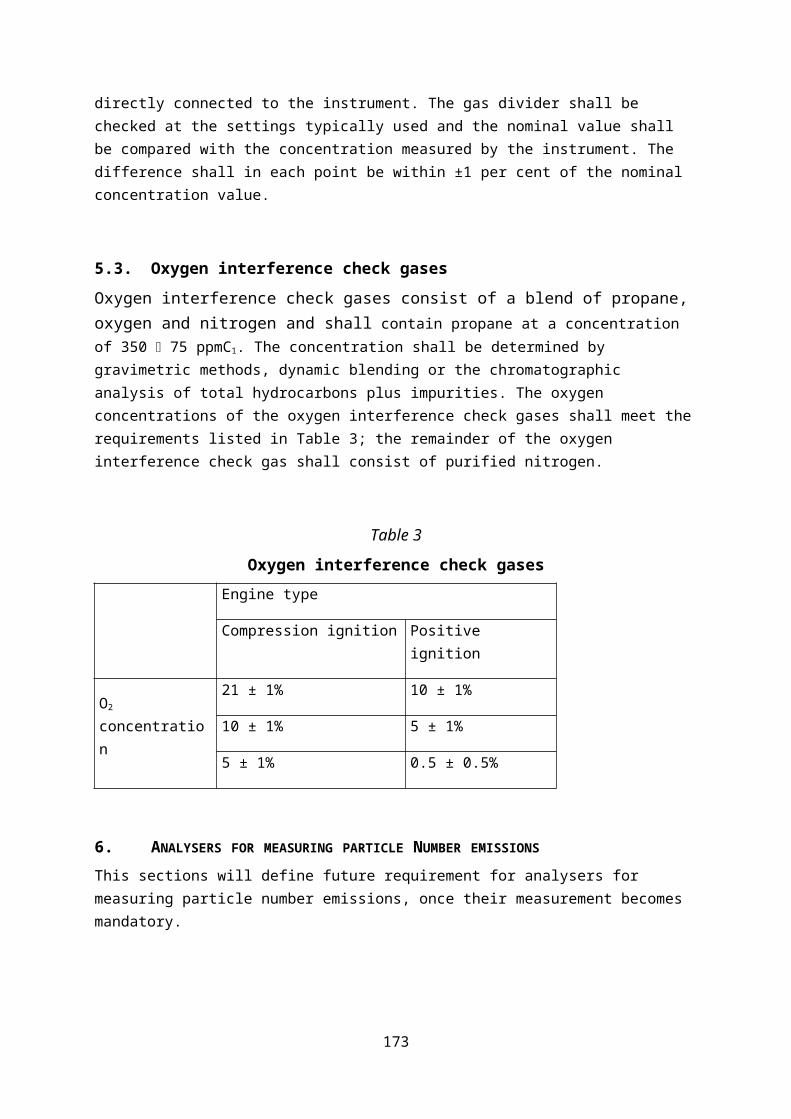
where:
Ha is the intake air humidity [g water per kg dry air]
cCO2 is the dry CO2 concentration [%]
cCO is the dry CO concentration [%]
α is the molar hydrogen ratio
8.2. Correction of NOx for ambient humidity and temperatureNOx emissions shall not be corrected for ambient temperature and humidity.
9. DETERMINATION OF THE INSTANTANEOUS GASEOUS EXHAUST COMPONENTS
9.1. IntroductionThe components in the raw exhaust shall be measured with the measurement and sampling analysers described in Appendix 2. The raw concentrations of relevant components shall be measured in accordance with Appendix 1. The data shall be time corrected and aligned in accordance with point 3.
9.2. Calculating NMHC and CH4 concentrationsFor methane measurement using a NMC-FID, the calculation of NMHC depends on the calibration gas/method used for the zero/span calibration adjustment. When a FID is used for THC measurement without a NMC, it shall be calibrated with propane/air or propane/N2 in the normal manner. For the calibration of the FID in series with a NMC, the following methods are permitted:
(a) the calibration gas consisting of propane/air bypasses the NMC;
(b) the calibration gas consisting of methane/air passes through the NMC.
It is strongly recommended to calibrate the methane FID with methane/air through the NMC.
In method (a), the concentrations of CH4 and NMHC shall be calculated as follows:
173

In method (b), the concentration of CH4 and NMHC shall be calculated as follows:
where:
cHC(w/oNMC) is the HC concentration with CH4 or C2H6 bypassing the NMC [ppmC1]
cHC(w/NMC)is the HC concentration with CH4 or C2H6 flowing through the NMC [ppmC1]
rh is the hydrocarbon response factor as determined in point 4.3.3.(b)
of Appendix 2
EM is the methane efficiency as determined in point 4.3.4.(a) of Appendix 2
EE is the ethane efficiency as determined in point 4.3.4(b) of Appendix 2
If the methane FID is calibrated through the cutter (method b), then the methane conversion efficiency as determined in point 4.3.4.(a) of Appendix 2 is zero. The density used for calculating the NMHC mass shall be equal to that of total hydrocarbons at 273.15 K and 101.325 kPa and is fuel-dependent.
10. DETERMINATION OF EXHAUST MASS FLOW RATE
10.1. IntroductionThe calculation of instantaneous mass emissions according to points 11 and 12 requires determining the exhaust mass flow rate. The exhaust mass flow rate shall be determined by one of the direct measurement methods specified in point 7.2 of Appendix 2. Alternatively, it is permissible to calculate the exhaust mass flow rate as described in points 10.2 to 10.4.
174

10.2. Calculation method using air mass flow rate and fuel mass flow rateThe instantaneous exhaust mass flow rate can be calculated from the air mass flow rate and the fuel mass flow rate as follows:
qmew ,i=qmaw ,i+qmf ,i
where:
qmew,i is the instantaneous exhaust mass flow rate [kg/s]
qmaw,i is the instantaneous intake air mass flow rate [kg/s]
qmf,i is the instantaneous fuel mass flow rate [kg/s]
If the air mass flow rate and the fuel mass flow rate or the exhaust mass flow rate are determined from ECU recording, the calculated instantaneous exhaust mass flow rate shall meet the linearity requirements specified for the exhaust mass flow rate in point 3 of Appendix 2 and the validation requirements specified in point 4.3 of Appendix 3.
10.3. Calculation method using air mass flow and air-to-fuel ratioThe instantaneous exhaust mass flow rate can be calculated from the air mass flow rate and the air-to-fuel ratio as follows:
qmew ,i=qmaw ,i ×(1+ 1A /F st ×❑i )
where:
A/ F st=138.0×(1+ α
4− ε
2+γ )
12.011+1.008 × α+15.9994 × ε+14.0067 × δ+32.0675 × γ
175
❑i=
(100−cCO ×10− 4
2−cHCw ×10−4)+(α
4×
1−2× cCO ×10−4
3.5 × cCO 2
1+cCO ×10−4
3.5 × cCO 2
− ε2− δ
2 )× (cCO 2+cCO ×10−4 )
4.764 ×(1+ α4− ε
2+γ )× (cCO2+cCO × 10−4+cHCw ×10−4 )
where:
qmaw,i is the instantaneous intake air mass flow rate [kg/s]
A/Fst is the stoichiometric air-to-fuel ratio [kg/kg]
i is the instantaneous excess air ratio
cCO2 is the dry CO2 concentration [%]
cCO is the dry CO concentration [ppm]
cHCw is the wet HC concentration [ppm]
α is the molar hydrogen ratio (H/C)
β is the molar carbon ratio (C/C)
γ is the molar sulphur ratio (S/C)
δ is the molar nitrogen ratio (N/C)
ε is the molar oxygen ratio (O/C)
Coefficients refer to a fuel Cβ Hα Oε Nδ Sγ with β = 1 for carbon based fuels. The concentration of HC emissions is typically low and may be omitted when calculating i.
If the air mass flow rate and air-to-fuel ratio are determined from ECU recording, the calculated instantaneous exhaust mass flow rate shall meet the linearity requirements specified for the exhaust mass flow rate in point 3 of Appendix 2 and the validation requirements specified in point 4.3 of Appendix 3.
10.4. Calculation method using fuel mass flow and air-to-fuel ratioThe instantaneous exhaust mass flow rate can be calculated from the fuel flow and the air-to-fuel ratio (calculated with A/Fst and i according to point 10.3) as follows:
176

qmew ,i=qmf ,i× (1+A / F st×❑i )
The calculated instantaneous exhaust mass flow rate shall meet the linearity requirements specified for the exhaust gas mass flow rate in point 3 of Appendix 2 and the validation requirements specified in point 4.3 of Appendix 3.
11. CALCULATING THE INSTANTANEOUS MASS EMISSIONS OF GASEOUS COMPONENTS
The instantaneous mass emissions [g/s] shall be determined by multiplying the instantaneous concentration of the pollutant under consideration [ppm] with the instantaneous exhaust mass flow rate [kg/s], both corrected and aligned for the transformation time, and the respective u value of Table 1. If measured on a dry basis, the dry-wet correction according to point 8.1 shall be applied to the instantaneous component concentrations before executing any further calculations. If occurring, negative instantaneous emission values shall enter all subsequent data evaluations. Parameter values shall enter the calculation of instantaneous emissions [g/s] as reported by the analyser, flow-measuring instrument, sensor or the ECU. The following equation shall be applied:
Aus unserer Sicht fehlt ein zu „0“ setzen negativer Messwerte. (Für gemessene Emissionen während der „Motor aus Phasen“ ist es in der RL implementiert, ansonsten jedoch nicht).
mgas ,i=ugas ∙ cgas ,i ∙ qmew , i
where:
mgas,i is the mass of the exhaust component “gas” [g/s]
ugas is the ratio of the density of the exhaust component “gas” and the overall
density of the exhaust as listed in Table 1
cgas,i is the measured concentration of the exhaust component “gas” in the exhaust
[ppm]
qmew,i is the measured exhaust mass flow rate [kg/s]
gas is the respective component
i number of the measurement
Table 1
177

Raw exhaust gas u values depicting the ratio between the densities of exhaust component or pollutant i [kg/m3] and the density of the exhaust gas [kg/m3](6)
Fuele
[kg/m3]
Component or pollutant i
NOx CO HC CO2 O2 CH4
gas [kg/m3]
2.053 1.250 (1) 1.9636 1.4277 0.716
ugas (2,6)
Diesel (B7)1.2943 0.001586
0.000966
0.000482 0.001517 0.001103 0.000553
Ethanol (ED95)
1.2768 0.0016090.000980
0.000780 0.001539 0.001119 0.000561
CNG(3)
1.2661 0.0016210.000987
0.000528(4) 0.001551 0.001128 0.000565
Propane1.2805 0.001603
0.000976
0.000512 0.001533 0.001115 0.000559
Butane1.2832 0.001600
0.000974
0.000505 0.001530 0.001113 0.000558
LPG(5) 1.2811 0.001602 0.000976
0.000510 0.001533 0.001115 0.000559
Petrol (E10)1.2931 0.001587
0.000966
0.000499 0.001518 0.001104 0.000553
Ethanol (E85)1.2797 0.001604
0.000977
0.000730 0.001534 0.001116 0.000559
(1) depending on fuel
(2) at = 2, dry air, 273 K, 101.3 kPa
(3) u values accurate within 0.2% for mass composition of: C=66-76%; H=22-25%; N=0-12%
(4) NMHC on the basis of CH2.93 (for THC the ugas coefficient of CH4 shall be used)
(5) u accurate within 0.2% for mass composition of: C3=70-90%; C4=10-30%
(6) ugas is a unitless parameter; the ugas values include unit conversions to ensure that the instantaneous emissions are obtained in the specified physical unit, i.e., g/s
Bei der Emissionsberechnung sind nicht alle Kraftstoffe aufgeführt. Z.B. ist bei Benzin nur
178
E10 aufgeführt. Ist ein Fahrzeug 98 Oktan-pflichtig und tankt somit Super+ handelt es sich jedoch um E5. Die Abgasberechnung erfolgt aufgrund des fehlenden E5 in der RL jedoch mit den Parametern für E10, somit wird hier ein Berechnungsfehler gemacht. Dieser ist gerade bei KV und CO2 nicht unerheblich.
12. CALCULATING THE INSTANTANEOUS PARTICLE NUMBER EMISSIONS
This sections will define the requirement for calculating instantaneous particle number emissions, once their measurement becomes mandatory.
13. DATA REPORTING AND EXCHANGE The data shall be exchanged between the measurement systems and the data evaluation software by a standardised reporting file as specified in point 2 of Appendix 8. Any pre-processing of data (e.g. time correction according to point 3 or the correction of the GPS vehicle speed signal according to point 7) shall be done with the control software of the measurement systems and shall be completed before the data reporting file is generated. If data are corrected or processed prior to entering the data reporting file, the original raw data shall be kept for quality assurance and control. Rounding of intermediate values is not permitted.
179


![White paper: HEVC analysers · Parabola Explorer Developed by Parabola Research, the analyser is available in trial and full versions from their website [5]. The software currently](https://img.dokumen.tips/doc/110x75/5e5a127c50fa6a72dc6ab7c1/white-paper-hevc-analysers-parabola-explorer-developed-by-parabola-research-the.jpg)