Embed Size (px)
Citation preview

Introducing
John McCabe with the Windows Server team
Windows Server 2016
PUBLISHED BY
Microsoft Press
A division of Microsoft Corporation
One Microsoft Way
Redmond, Washington 98052-6399
Copyright © 2016 by Microsoft Corporation
All rights reserved. No part of the contents of this book may be reproduced or transmitted in any
form or by any means without the written permission of the publisher.
ISBN: 978-0-7356-9774-4
Microsoft Press books are available through booksellers and distributors worldwide. If you need
support related to this book, email Microsoft Press Support at [email protected]. Please tell us
what you think of this book at http://aka.ms/tellpress.
This book is provided “as-is” and expresses the author’s views and opinions. The views, opinions and
information expressed in this book, including URL and other Internet website references, may change
without notice.
Some examples depicted herein are provided for illustration only and are fictitious. No real association
or connection is intended or should be inferred.
Microsoft and the trademarks listed at http://www.microsoft.com on the “Trademarks” webpage are
trademarks of the Microsoft group of companies. All other marks are property of their respective
owners.
Acquisitions Editor: Kim Spilker
Developmental Editor: Bob Russell, Octal Publishing, Inc.
Editorial Production: Dianne Russell, Octal Publishing, Inc.
Copyeditor: Bob Russell
• Hundreds of titles available – Books, eBooks, and online resources from industry experts
• Free U.S. shipping
• eBooks in multiple formats – Read on your computer, tablet, mobile device, or e-reader
• Print & eBook Best Value Packs
• eBook Deal of the Week – Save up to 60% on featured titles
• Newsletter and special offers – Be the first to hear about new releases, specials, and more
• Register your book – Get additional benefits
microsoftpressstore.com
Visit us today at

ii Contents
Contents Introduction ............................................................................................................................................. vi
Acknowledgments .................................................................................................................................................................. vi
Free ebooks from Microsoft Press .................................................................................................................................. vii
Errata, updates, & book support ..................................................................................................................................... vii
We want to hear from you ................................................................................................................................................ viii
Stay in touch ........................................................................................................................................................................... viii
Chapter 1: Introduction to Microsoft Windows Server 2016 ............................................................. 1
Introduction ............................................................................................................................................................................... 1
Cloud ready with Windows Server 2016 ......................................................................................................................... 2
Security .................................................................................................................................................................................... 3
Software-defined datacenter .......................................................................................................................................... 3
Microsoft loves Linux! ....................................................................................................................................................... 5
System Center 2016 ................................................................................................................................................................ 6
Chapter 2: Software-defined datacenter ............................................................................................... 9
Compute ...................................................................................................................................................................................... 9
Hyper-V ................................................................................................................................................................................... 9
VM groups .......................................................................................................................................................................... 12
True VM mobility .............................................................................................................................................................. 17
VM configuration version ............................................................................................................................................. 22
New configuration file format ..................................................................................................................................... 24
Production checkpoints ................................................................................................................................................. 25
Hot add and hot remove for network adapters and memory ....................................................................... 27
Failover cluster ....................................................................................................................................................................... 31
iii Contents
Creating a cloud witness by using Azure ................................................................................................................ 31
Shared VHDX improvements ....................................................................................................................................... 33
Improved cluster logs ..................................................................................................................................................... 35
Active memory dump ..................................................................................................................................................... 37
Network name diagnostics........................................................................................................................................... 38
Cluster operating system rolling upgrade ............................................................................................................. 39
Workgroup and multidomain clusters ..................................................................................................................... 45
SMB multichannel and multi-NIC cluster networks ........................................................................................... 45
VM improvements ........................................................................................................................................................... 46
Storage ...................................................................................................................................................................................... 46
Storage Replica ................................................................................................................................................................. 46
Scenarios ............................................................................................................................................................................. 49
Storage Replica in Windows Server 2016 ............................................................................................................... 53
Storage Spaces Direct ......................................................................................................................................................... 54
Implementation details .................................................................................................................................................. 56
Improved scalability ........................................................................................................................................................ 57
Storage Spaces Direct optimized pool .................................................................................................................... 58
Failure scenarios ............................................................................................................................................................... 58
Deduplication ......................................................................................................................................................................... 59
Storage Quality of Service ................................................................................................................................................. 61
Networking .............................................................................................................................................................................. 64
Network Controller .......................................................................................................................................................... 67
RAS Gateway multitenant BGP router ...................................................................................................................... 69
Software Load Balancing ............................................................................................................................................... 70
Datacenter firewall ........................................................................................................................................................... 71
Web Application Proxy .................................................................................................................................................. 72
Web Application Proxy troubleshooting ................................................................................................................ 83
Chapter 3: Application platform .......................................................................................................... 87
Modernizing traditional apps .......................................................................................................................................... 87
Microservices .......................................................................................................................................................................... 88
Azure Hybrid Use Benefit .................................................................................................................................................. 89
Nano Server ............................................................................................................................................................................ 89
Understanding Nano Server ........................................................................................................................................ 89
Deploying Nano Server ................................................................................................................................................. 92
Specializing Nano Server .............................................................................................................................................. 93
Remotely managing Nano Server ............................................................................................................................. 94
Service branching ................................................................................................................................................................. 96
Containers ................................................................................................................................................................................ 97
iv Contents
What is a container? ....................................................................................................................................................... 97
Why use containers? ....................................................................................................................................................... 99
Windows Server containers versus Hyper-V containers ................................................................................... 99
Chapter 4: Security and identity ......................................................................................................... 106
Shielded VMs ........................................................................................................................................................................ 107
Threat-resistant technologies ........................................................................................................................................ 108
Control Flow Guard ....................................................................................................................................................... 108
Device Guard on Windows Server 2016 ................................................................................................................ 109
What is Device Guard ................................................................................................................................................... 109
Enhanced Kernel Mode protection using Hypervisor Code Integrity ....................................................... 109
Deploy configurable code Integrity policy........................................................................................................... 110
Create code Integrity policy for general server usage .................................................................................... 110
Create code integrity policy for lockdown server ............................................................................................. 111
Deploy code integrity policy...................................................................................................................................... 111
Credential Guard ............................................................................................................................................................ 111
Remote credential guard ............................................................................................................................................ 113
Windows Defender ........................................................................................................................................................ 114
Threat detection technologies ....................................................................................................................................... 114
Securing privileged access .............................................................................................................................................. 117
Just-in-Time and Just Enough Administration ........................................................................................................ 117
A strategy for securing privileged access .................................................................................................................. 118
Short-term plan .............................................................................................................................................................. 119
Medium-term plan ........................................................................................................................................................ 120
Long-term plan ............................................................................................................................................................... 122
Identity .................................................................................................................................................................................... 123
Active Directory Domain Services............................................................................................................................ 123
Chapter 5: Systems management ....................................................................................................... 131
Windows PowerShell improvements .......................................................................................................................... 131
Package management ...................................................................................................................................................... 132
Windows PowershellGet and NuGet ...................................................................................................................... 133
Windows PowerShell Classes ......................................................................................................................................... 137
Windows PowerShell script debugging ..................................................................................................................... 138
Break All ............................................................................................................................................................................. 138
Remote editing ............................................................................................................................................................... 138
Remote debugging ....................................................................................................................................................... 138
Job debugging ................................................................................................................................................................ 139
Runspace debugging .................................................................................................................................................... 140
Desired State Configuration ........................................................................................................................................... 141
v Contents
DSC Local Configuration Manager .......................................................................................................................... 141
New methods in LCM ................................................................................................................................................... 145
DSC partial configurations .......................................................................................................................................... 147
Setting up the LCM Meta Configuration .............................................................................................................. 147
Authoring the configurations .................................................................................................................................... 149
Deploying the configurations ................................................................................................................................... 151
System Center 2016 ........................................................................................................................................................... 152
Operations Management Suite ................................................................................................................................ 154
Server management tools ............................................................................................................................................... 162
About the author ................................................................................................................................. 168
[Type text]
vi Introduction
Introduction Windows Server has powered a generation of organizations, from small businesses to large
enterprises. No matter what your role in IT, you can be guaranteed you that have touched Windows
Server at some point in your career or at very least you have seen it from afar! This book introduces
you to Windows Server 2016, which is the next version of Windows Server. No matter what your area
of expertise, this book will introduce you to the latest developments in Windows Server 2016.
Each chapter has been written by either field experts or members of the product group, giving you the
latest information on every improvement or new feature that is included in this version of Windows
Server. This information will help you to prepare for Windows Server 2016 and give you the means to
develop and design a path to introduce Windows Server 2016 into your environment and take full
advantage of what is to come. This book is being written at a time when the product is still evolving
and it should be noted that things might change or not appear in the final version of Windows Server
2016 when released. All guidance in the chapters is meant to be tried and evaluated in a test
environment; you should not implement it in a production environment.
This book assumes that you are familiar with key concepts surrounding Windows Server (i.e., Microsoft
Hyper-V, Networking, and Storage) as well as cloud technologies such as Microsoft Azure. In this
book, we cover a variety of concepts irelated to the technology and present scenarios with a customer
focus, but it is not intended as a how-to or design manual. You can use other sources, including the
online Microsoft resources, to stay up to date with the latest developments on the roles and features
of Windows Server 2016. The online resources will also contain the latest how-to procedures and
information about designing a Windows Server 2016 infrastructure for your business.
Acknowledgments We’d like to thank all of the contributors who made this book possible:
David Holladay
Mitch Tulloch
Ned Pyle
Claus Joergensen
Matt Garson
John Marlin
Robert Mitchell
Deepak Srivastava
Shababir Ahmed
vii Introduction
Ramnish Singh
Ritesh Modi
Jason M. Anderson
Schumann Ge
Yuri Diogenes
David Branscome
Shabbir Ahmed
Ramnish Singh
Andrew Mason
Neil Peterson
The staff at Microsoft Press who makes these titles possible!
Finally, to anyone I haven’t directly mentioned, for all the help that has been provided, thank you!
Free ebooks from Microsoft Press
From technical overviews to in-depth information on special topics, the free ebooks from Microsoft
Press cover a wide range of topics. These ebooks are available in PDF, EPUB, and Mobi for Kindle
formats, ready for you to download at:
http://aka.ms/mspressfree
Check back often to see what is new!
Errata, updates, & book support We’ve made every effort to ensure the accuracy of this book and its companion content. You
can access updates to this book—in the form of a list of submitted errata and their related
corrections—at:
https://aka.ms/IntroWinServ2016/errata
If you discover an error that is not already listed, please submit it to us at the same page.
If you need additional support, email Microsoft Press Book Support at [email protected].
Please note that product support for Microsoft software and hardware is not offered through the
previous addresses. For help with Microsoft software or hardware, go to http://support.microsoft.com.

viii Introduction
We want to hear from you
At Microsoft Press, your satisfaction is our top priority, and your feedback our most valuable asset.
Please tell us what you think of this book at:
http://aka.ms/tellpress
The survey is short, and we read every one of your comments and ideas. Thanks in advance for your
input!
Stay in touch
Let’s keep the conversation going! We’re on Twitter: http://twitter.com/MicrosoftPress.
1 CHAPTER 1 | Introduction to Microsoft Windows Server 2016
C H A P T E R
1
Introduction to Microsoft Windows Server 2016 Whether you are a small- to mid-size business, a large enterprise, or a
cloud service provider, the demand on what IT must deliver is a rapidly
changing landscape. Customers want to access their applications in a
variety of ways and be confident that they can complete their daily tasks in
a secure and efficient manner. They simply are not concerned about how
IT infrastructures are made up and the challenges that team’s supporting
these environments experience a day-to-day basis.
Introduction If you run an IT environment today, how do you meet the aforementioned challenges? Can your
applications and infrastructure meet the demands placed on it? Can you meet the rate of innovation
the cloud offers or the agility and speed of delivery? In these respects, there are an increasing number
of challenges facing the on-premises infrastructure.
However, not everyone is ready to move to the cloud, and there will be many cases in which you can’t
because of a multitude of reasons; for example, contractual commitments that stipulate data can’t
move to the cloud.
2 CHAPTER 1 | Introduction to Microsoft Windows Server 2016
Even if you can’t or don’t want to move to the cloud today, it is still important that you begin the
journey to modernize your infrastructure so that you can take advantage of all the developments and
advances that Microsoft has made gleaned from its cloud experience and incorporated into Windows
Server 2016.
Cloud ready with Windows Server 2016
Simply put, Windows Server 2016 is the cloud-ready operating system (OS) that delivers new layers of
security and Microsoft Azure-inspired innovation for the applications and infrastructure that power
your business.
For this release, Microsoft has spent a considerable amount of time reaching out to customers and
gathering feedback of what is important and how it can meet the future needs for customer’s
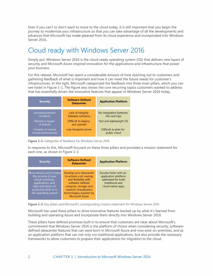
infrastructures. In this light, Microsoft categorized the feedback into three main pillars, which you can
see listed in Figure 1-1. The figure also shows the core recurring topics customers wanted to address
that has essentially driven the innovative features that appear in Windows Server 2016 today.
Figure 1-1: Categories of feedback for Windows Server 2016
In response to this, Microsoft focused on these three pillars and provided a mission statement for
each one, as shown in Figure 1-2.
Figure 1-2: Key pillars and Microsoft’s corresponding mission statement for Windows Server 2016
Microsoft has used these pillars to drive innovative features backed up by what it’s learned from
building and operating Azure and incorporate them directly into Windows Server 2016.
These pillars have defined promises built in to ensure that customers are clear about Microsoft’s
commitment that Windows Server 2016 is the platform of choice when considering security, software-
defined datacenter features that can were born in Microsoft Azure and now exist on-premises, and as
an application platform that can not only run traditional applications, but also provide the necessary
frameworks to allow customers to prepare their applications for migration to the cloud.
3 CHAPTER 1 | Introduction to Microsoft Windows Server 2016
The following subsections dive deeper into the pillars and what Microsoft promises to deliver and,
more important, how it will deliver on these promises.
Security
Windows Server 2016 gives you the power to prevent attacks and detect suspicious activity with new
features to control privileged access, protect virtual machines (VMs), and harden the platform against
emerging threats. Here’s what Windows Server 2016 can do for you:
Prevent the risk associated with compromised administrative credentials
Using the new privileged identity management features, you can limit access to Just Enough and
Just-in-Time 1. And, using Credential Guard, you can prevent administrative credentials from
being stolen by Pass-the-Hash attacks.
Protect your VMs from compromised fabric administrators by using shielded VMs
A shielded VM is a Generation 2 VM that has a virtual Trusted Platform Module (TPM), is
encrypted by using BitLocker, and can run only on approved hosts in the fabric.
Reduce your datacenter footprint and increase availability with just-enough OS.
The new Nano Server deployment option is 25 times smaller than Windows Server, while still
offering a desktop experience. This minimizes the attack surface, increases availability, and
reduces deployment time, resource usage, and startup time.
Add even more protection to every deployment of Windows Server 2016.
Whether you’re running in any cloud or on-premises, you can take advantage of additional
security features such as Code Integrity and Control Flow Guard to ensure that only permitted
binaries are run and protect against unknown vulnerabilities.
Detect malicious behavior through enhanced security auditing optimized for threat detection.
Using new audit categories for group membership and PNP to identify and add additional
information to audit events, administrators can dive deeper than ever to discover new threats
Defend against malware attacks by using the built-in antimalware
Windows Defender is now included in Windows Server 2016 and optimized to support the various
server roles and integrate with Windows PowerShell for malware scanning.
Limit exposure in case of a security intrusion
If you were to suffer a security breach, Windows Server 2016 can limit the exposure by
segmenting your network based on workload or business needs using a distributed firewall and
network security groups. You can apply rich policies within and across segments.
Use Hyper-V Containers for a unique additional level of isolation for containerized applications
without any changes to the container image.
Hyper-V containers provide isolation at the hardware level, giving administrators the peace of
mind that they have come to appreciate with hardware-based virtualization protection as it
incorporates the same isolation methods.
Software-defined datacenter
Windows Server 2016 delivers a more flexible and cost-efficient OS for your datacenter, using
software-defined compute, storage, and network virtualization features inspired by Azure.
4 CHAPTER 1 | Introduction to Microsoft Windows Server 2016
Software-defined compute
The following list presents just some of the amazing new features that fall under the software-defined
compute stack for Windows Server 2016:
Minimize attack surface, increase availability, and reduce resource usage with just-enough OS
using the Nano Server deployment option, which is 25 times smaller than Windows Server while
still providing a desktop experience.
Make the move to the cloud easier by running your workloads in Microsoft Hyper-V, the same
hypervisor that runs Azure and Azure Stack.
Deploy applications on multiple operating systems with best-in-class support for Linux on
Hyper-V.
Upgrade infrastructure clusters to Windows Server 2016 with zero downtime for your
application/workload, and without requiring new hardware, using mixed-mode cluster upgrades.
Support.
Increase application availability with improved cluster resiliency to transient failures in the network
and storage.
Add incremental resiliency to your clusters by using Cloud Witness to connect to resources in
Azure.
Automate server management with native tools such as Desired State Configuration and Windows
PowerShell 5.0.
Manage Windows servers from anywhere by using the new web-based GUI—Server management
tool—a service running in Azure. Especially useful for managing headless deployment options
such as Nano Server and Server Core.
Software-defined storage
The following list introduces some of the enterprise grade storage features coming in Windows
Server 2016:
Build highly available and scalable software-defined storage at a fraction of the cost of a Storage-
Area Network (SAN) or Network-Attached Storage (NAS). Storage Spaces Direct uses standard
servers with local storage to create converged or hyper-converged storage architectures.
Create affordable business continuity and disaster recovery among datacenters with Storage
Replica synchronous storage replication.
Ensure that users of business-critical applications have priority access to storage resources using
Storage Quality of Service (QoS) features.
Software-defined networking
The following lists some of the new features around software-defined networking coming in Windows
Server 2016:
Deploy complex workloads with hundreds of networking policies (isolation, QoS, security, load
balancing, switching, routing, gateway, DNS, etc.) using a scalable network controller in a matter
of seconds, similar to how we do it in Azure.
Dynamically segment your network based on workload needs using an Azure-inspired distributed
firewall and network security groups to apply rich policies within and across segments. Route or
mirror traffic to third-party virtual appliances for even higher levels of security.
5 CHAPTER 1 | Introduction to Microsoft Windows Server 2016
Offer greater service availability with software-based scale-out and scale-up resiliency for both the
infrastructure (host, software load balancer, gateway, network controller) and the workloads.
Take control of your hybrid workloads, including running them in containers, and move them
across servers, racks, and clouds utilizing the power of VXLAN and NVGRE based virtual
networking and multitenanted hybrid gateways.
Optimize your cost/performance when you converge Remote Direct Memory Access (RDMA) and
tenant traffic on the same teamed Network Interface Cards (NICs), thereby driving down cost
while providing needed performance guarantees at 40G and beyond.
Application platform
Windows Server 2016 delivers new ways to deploy and run your applications, whether on-premises or
in Azure, using new capabilities such as Windows containers and the lightweight Nano Server
deployment option.
Containers in Windows Server 2016 offer the agility and density required for modern cloud
applications. Windows Server containers brings containers to the Windows ecosystem and
Hyper-V containers with its additional layer of isolation for sensitive applications with no
additional coding required.
Use the lightweight Nano Server deployment option for the agility and flexibility today’s
application developers need. It’s the perfect option for running applications from containers or
micro services.
Run traditional first-party applications such as SQL Server 2016 with best-in-class performance,
security and availability.
Save money by bringing the Windows Server licenses you own to Azure, and pay the lower base
compute rate with the Azure Hybrid Use Benefit. (SA required.)
Service Branching
With Nano Server, you get more active updates to the operating system, which will enable new
features during its lifecycle and give developers the tools to consistently adopt the latest Agile
and/or secure technologies that Microsoft deploys.
Throughout this book we will examine each of these elements closely and provide further information
about each category and feature mentioned.
Microsoft loves Linux!
It is no secret that Microsoft has made major investments to ensure Linux gets an enterprise grade
experience in the Microsoft ecosystem. Microsoft has made contributions to the Linux kernel and
actively maintains the Linux Integration Services (LIS) to ensure a fully enlightened experienced while
running Linux on Hyper-V.
Microsoft fully supports the following distributions on Hyper-V today, with more being added in the
future.
Red Hat Linux
SUSE
OpenSUSE
CentOS
6 CHAPTER 1 | Introduction to Microsoft Windows Server 2016
Ubuntu
Debian
Oracle Linux
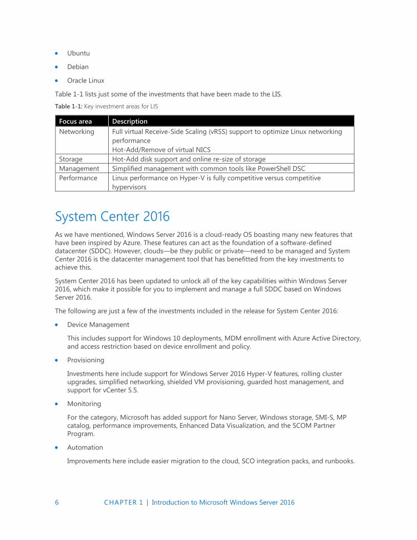
Table 1-1 lists just some of the investments that have been made to the LIS.
Table 1-1: Key investment areas for LIS
Focus area Description
Networking Full virtual Receive-Side Scaling (vRSS) support to optimize Linux networking
performance
Hot-Add/Remove of virtual NICS
Storage Hot-Add disk support and online re-size of storage
Management Simplified management with common tools like PowerShell DSC
Performance Linux performance on Hyper-V is fully competitive versus competitive
hypervisors
System Center 2016 As we have mentioned, Windows Server 2016 is a cloud-ready OS boasting many new features that
have been inspired by Azure. These features can act as the foundation of a software-defined
datacenter (SDDC). However, clouds—be they public or private—need to be managed and System
Center 2016 is the datacenter management tool that has benefitted from the key investments to
achieve this.
System Center 2016 has been updated to unlock all of the key capabilities within Windows Server
2016, which make it possible for you to implement and manage a full SDDC based on Windows
Server 2016.
The following are just a few of the investments included in the release for System Center 2016:
Device Management
This includes support for Windows 10 deployments, MDM enrollment with Azure Active Directory,
and access restriction based on device enrollment and policy.
Provisioning
Investments here include support for Windows Server 2016 Hyper-V features, rolling cluster
upgrades, simplified networking, shielded VM provisioning, guarded host management, and
support for vCenter 5.5.
Monitoring
For the category, Microsoft has added support for Nano Server, Windows storage, SMI-S, MP
catalog, performance improvements, Enhanced Data Visualization, and the SCOM Partner
Program.
Automation
Improvements here include easier migration to the cloud, SCO integration packs, and runbooks.
7 CHAPTER 1 | Introduction to Microsoft Windows Server 2016
Self-Service
In the area of self-service, you can benefit from improved usability and performance, an HTML5
self-service portal, and the new exchange connector.
Data Protection
Here, you can take advantage of investments that include support for Azure Express Route,
shielded VM, and Storage spaces direct.
All of these improvements in the System Center suite give organizations the power they need to
create the next generation of the cloud. However, the investments don’t stop there, System Center
2016 can now natively access new integrations into Microsoft Operations Management Suite.
This integration unlocks new possibilities to complement the already wide-ranging capabilities of
System Center and gives administrators greater visibility, protection, control, and security into their
IT environment at cloud scale. Operations Management Suite reporting capabilities and native
integration into Microsoft Power BI with which administrators can create powerful and dynamic
reports and visualizations in a matter of clicks.
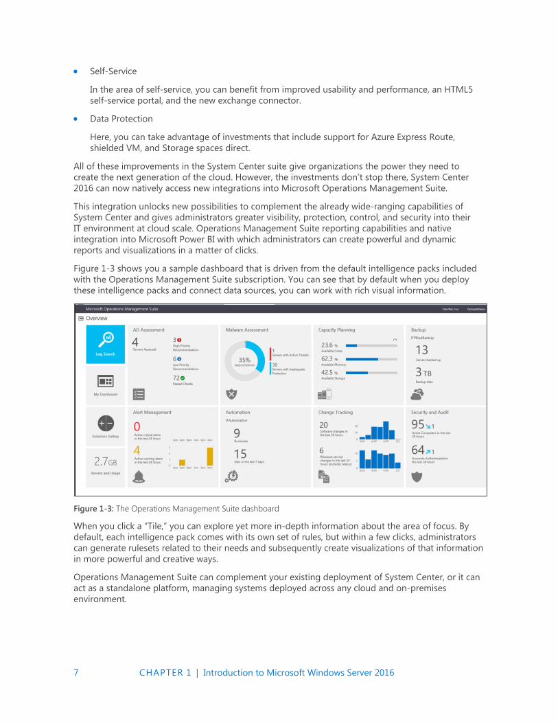
Figure 1-3 shows you a sample dashboard that is driven from the default intelligence packs included
with the Operations Management Suite subscription. You can see that by default when you deploy
these intelligence packs and connect data sources, you can work with rich visual information.
Figure 1-3: The Operations Management Suite dashboard
When you click a “Tile,” you can explore yet more in-depth information about the area of focus. By
default, each intelligence pack comes with its own set of rules, but within a few clicks, administrators
can generate rulesets related to their needs and subsequently create visualizations of that information
in more powerful and creative ways.
Operations Management Suite can complement your existing deployment of System Center, or it can
act as a standalone platform, managing systems deployed across any cloud and on-premises
environment.

8 CHAPTER 1 | Introduction to Microsoft Windows Server 2016
The Operations Management Suite platform is divided into the following pillars:
Insights and Analytics
This pillar focuses on collecting data from multiple sources, correlating activities, and providing
mechanisms with which you can act on the results using alerts and searches to trigger activities. It
is also capable of mapping and understanding the dependencies of workloads in the same
capacity.
Security and Compliance
This pillar, which is built from Microsoft security data and analysis, helps you to prevent, detect,
and respond to threats more effectively than ever before. With the increased visibility into what is
happening into your environment, you can mitigate situations and enforce policies to fully control
your IT ecosystem that spans the cloud.
Automation and Control
This pillar concentrates on giving back control to IT administrators. Here, you can trigger
runbooks from alerts generated in the Insights and Analytics pillar and driving operational
efficiencies through automation.
Protection and Recovery
This pillar is based on giving simple and efficient cloud backup and disaster recovery to
organizations today. With it, you can automate your disaster recovery runbook in a controlled and
efficient manner, ensuring success every time.
Although these pillars are important to understand what makes up the Operations Management Suite
and how you can approach your adoption of the suite. It does not represent all of the potential
solution packs available or coming in the gallery today. Figure 1-4 depicts the solution packs
customers can use to gain further intelligence and visibility on their IT environment, both today and
what’s coming in the future:
Figure 1-4: Solutions available in Operations Management Suite today as well as future solutions
We will examine Operations Management Suite in greater depth later in this book and show some
simple examples of how it complements Windows Server 2016.
9 CHAPTER 2 | Software-defined datacenter
C H A P T E R
2
Software-defined datacenter In this chapter, we dive into the new or improved features in Windows
Server 2016 that can bring a software-defined datacenter to life. If you are
cloud service provider or want to build a platform to host your next
generation of applications, Windows Server 2016 is the key to achieving
this task. This chapter is broken into three main components: Compute,
Storage, and Networking. These components are the underpinning to any
software-defined datacenter, and in each section we will examine them
into more detail.
Compute In this section we focus on everything Compute with a major focus on Hyper-V and what is new within
Windows Server 2016. We will discuss all the features which will underpin world class software defined
datacenters.
Hyper-V
By Robert Mitchell, Deepak Srivastava, Shabbir Ahmed, and Ramnish Singh
Microsoft Hyper-V virtualization technology has been enhanced in a number of ways in Windows
Server 2016, and this section describes several of these improvements. Robert Mitchell demonstrates
a new feature called Virtual Machine Groups and also describes the new cross-version virtual machine
(VM) mobility capabilities of the platform. Deepak Srivastava walks you through the new VM
configuration version, new configuration file format, and new support for using checkpoints in
production environments. Finally, Shababir Ahmed and Ramnish Singh demonstrate the new hot add
and remove capability for network adapters and memory that is now supported by the Hyper-V role.

10 CHAPTER 2 | Software-defined datacenter
Scale
Windows Server 2016, delivers new industry-leading scalability to virtualize any and every workload
without exception. The following table shows you a comparison of the journey we have taken from
Windows Server 2012/2012R2 to now:
Description
Windows Server 2012/2012 R2,
Standard and Datacenter
Windows Server 2016 Standard,
and Datacenter
Physical (host) memory
support
Up to 4 TB per physical server Up to 24 TB per physical server (6x)
Physical (host) logical
processor support
Up to 320 LPs Up to 512 LPs
VM memory support Up to 1 TB per VM Up to 16 TB per VM (16x)
VM virtual processor
support
Up to 64 VPs per VM Up to 240 VPs per VM (3.75x)
Nested virtualization
Nested virtualization makes it possible for you to run Hyper-V as a guest VM running on Hyper-V! It
exposes hardware virtualization extensions to a VM. There are some requirements for running this
technology:
Windows Server 2016 or Windows 10
Minimum 4 GB RAM for the Host
Intel VT-x processors (as of this writing)
EPT Support
Nested VM running Hyper-V must have dynamic memory disabled
To turn on nested virtualization, first, on the host, you must run the following Windows PowerShell
command against a VM that you have created but have not yet turned on.
Set-VMProcessor -VMName <VMName> -ExposeVirtualizationExtensions $true
If you want to provide connectivity options for the guest VMs that will reside within your nested
Hyper-V machine, you have two choices. The first option is to turn on MAC spoofing for the guest VM.
This will allow its guest VMs to send traffic over the network. To turn on MAC spoofing on the host
Hyper-V switch, use the following command:
Get-VMNetworkAdapter -VMName <VMName> | Set-VMNetworkAdapter -MacAddressSpoofing On
Your second option is NAT. You need to turn on NAT on the nested Hyper-V VM by using the
following commands:
new-vmswitch -name VmNAT -SwitchType Internal
New-NetNat –Name LocalNAT –InternalIPInterfaceAddressPrefix “192.168.100.0/24”
When this is done, you need to assign an IP address to the new internal adapter. This essentially will
be the gateway address for the VMs running under the nested Hyper-V. Here’s the Windows
PowerShell command to do this:
get-netadapter "vEthernet (VmNat)" | New-NetIPAddress -IPAddress 192.168.100.1 -AddressFamily IPv4 -PrefixLength 24
11 CHAPTER 2 | Software-defined datacenter
Each nested guest VM needs to have an IP address set and its gateway set as follows:
get-netadapter "Ethernet" | New-NetIPAddress -IPAddress 192.168.100.2 -DefaultGateway 192.168.100.1 -AddressFamily IPv4 -PrefixLength 24
More info See the following link https://msdn.microsoft.com/virtualization/ hyperv_on_windows/user_guide/nesting.
Linux secure boot
Linux VMs that are created as Generation 2 VMs can now utilize secure boot. To do this, you must
turn on the VM to use the Microsoft UEFI Cert Authority by running the following Windows
PowerShell command:
Set-VMFirmware vmname -SecureBootTemplate MicrosoftUEFICertificateAuthority
You also can turn on secure boot via the Hyper-V manager or Virtual Machine Manager.
Currently, only certain distributions support secure boot:
Ubuntu 14.04 and later
SUSE Linux Enterprise Server 12 and later
Red Hat Enterprise Linux 7.0 and later
CentOS 7.0 and later
Integration services
Updates to integration services for Windows guests are distributed through Windows Update. For
service providers and private cloud hosters, this puts the control of applying updates into the hands
of the tenants who own the VMs. Tenants can now update their Windows VMs with all updates,
including the integration services, using a single method.
Hyper-V Manager improvements
There are some new improvements to the Hyper-V Manager. Let’s take a look at them:
Alternate credentials support You can now use a different set of credentials in Hyper-V
Manager when you connect to another Windows Server 2016 or Windows 10 remote host. You
also can save these credentials to make it easier to sign in again.
Manage earlier versions With Hyper-V Manager in Windows Server 2016 and Windows 10, you
can manage computers running Hyper-V on Windows Server 2012, Windows 8, Windows Server
2012 R2, and Windows 8.1.
Updated management protocol Hyper-V Manager has been updated to communicate with
remote Hyper-V hosts using the Web Services Management (WS-MAN) protocol, which permits
CredSSP, Kerberos, or NTLM authentication. When you use CredSSP to connect to a remote
Hyper-V host, you can do a live migration without turning on constrained delegation in Active
Directory. The WS-MAN–based infrastructure also makes it easier to set up a host for remote
management. WS-MAN connects over port 80, which is open by default.
Host resource protection
One of the problems with virtualization has always been the struggle to prevent a VM from using
more than its fair share of resources. This overuse could potentially affect the host system
performance and guest VMs. By default, this monitoring and protection is turned off; to turn it on, run
the following:
12 CHAPTER 2 | Software-defined datacenter
Set-VMProcessor -EnableHostResourceProtection $true
This will turn on a monitoring process that scans for excessive usage and will limit the resources of
any VM that might be causing the issue, thereby isolating the impact.
Connected Standby
When the Hyper-V role is installed on a computer that uses the Always On/Always Connected (AOAC)
power model, the Connected Standby power state is now available.
Device assignment
Using this feature, you can give a VM direct and exclusive access to some PCIe hardware devices.
Using a device in this way bypasses the Hyper-V virtualization stack, which results in faster access.
More info See the following link http://blogs.technet.com/b/virtualization/archive/2015/11/19/ discrete-device-assignment.aspx.
Windows PowerShell Direct
Windows PowerShell Direct gives you a way to run Windows PowerShell commands in a VM from the
host. Windows PowerShell Direct runs between the host and the VM. This means it doesn't require
networking or firewall requirements, and it works regardless of your remote management
configuration.
Windows PowerShell Direct works much like remote Windows PowerShell except that you do not
need network connectivity.
To connect to the VM from a host, use the Enter-PSSession cmdlet, as follows:
Enter-PSSession -VMName <VMName>
You will be prompted for credentials and then you can manage the VM from this PSSession.
The Invoke-Command cmdlet has been updated to perform similar tasks; for example, you can
execute a script from the host against the VM, as shown here:
Invoke-Command -VMName <vmname> -FilePath C:\Scripts\MyTestScript.ps1
Remote Direct Memory Access
In Windows Server 2016, you can now turn on Remote Direct Memory Access (RDMA) on NICs that
are not teamed or without Switch Embedded Teaming (SET). We discuss this later in this chapter.
More info To learn more about working with RDMA, go to https://technet.microsoft.com/ library/mt403349.aspx.
VM groups
To make the management of multiple VMs easier, Windows Server 2016 has added support for
groupings of VMs. VM groups are exactly what the name implies: logical groupings of VMs.
There are two different types of groups:
VM collections
Management collections

13 CHAPTER 2 | Software-defined datacenter
A VM collection group is a logical collection of VMs. This type of group makes it possible for
administrators to carry out their tasks on specific groups, rather than having to carry them out on
each individual VM separately.
A management collection group is a logical collection of VM collection groups. With this type of
group, administrators can nest VM collections as needed.
In Hyper-V Manager, it is possible to carry out operations on multiple VMs simply by selecting
multiple objects, as illustrated in Figure 2-1
Figure 2-1: Options available on VM
You can carry out these tasks without using VM groups, but the effort is somewhat limited. You can
do more by using VM groups. Two scenarios for which VM groups are useful are backups and VM
replicas. Even though it is fairly easy to back up or replicate a VM, and although such functionality has
been included in Windows Server for some time, all VMs are dealt with separately. In some situations,
because of distributed applications, VMs should be treated as a unit. This is true in both backup and
VM replica situations.
Creating VM collections
The following new Windows PowerShell cmdlets have been introduced to facilitate scripting:
New-VMGroup
Get-VMGroup
Remove-VMGroup
Add-VMGroupMember
Remove-VMGroupMember
Rename-VMGroup
As of this writing, VM group management tools are still being developed; however, they will be visible
in Windows PowerShell, Hyper-V Manager, and the upcoming version of Microsoft System Center
Virtual Machine Manager.
To group together the three example VMs shown in Figure 2-2, you need to do the following:
1. Create a VM group.
2. Add the VMs to the group membership.
14 CHAPTER 2 | Software-defined datacenter
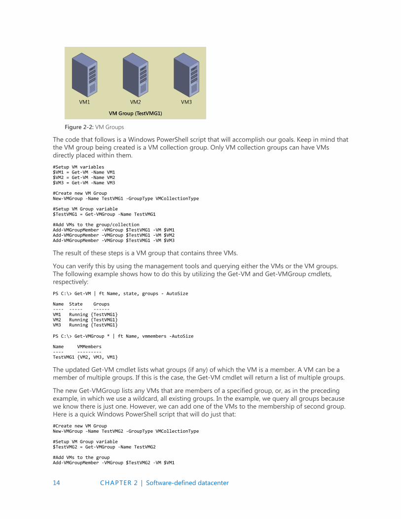
Figure 2-2: VM Groups
The code that follows is a Windows PowerShell script that will accomplish our goals. Keep in mind that
the VM group being created is a VM collection group. Only VM collection groups can have VMs
directly placed within them.
#Setup VM variables $VM1 = Get-VM -Name VM1 $VM2 = Get-VM -Name VM2 $VM3 = Get-VM -Name VM3 #Create new VM Group New-VMGroup -Name TestVMG1 -GroupType VMCollectionType #Setup VM Group variable $TestVMG1 = Get-VMGroup -Name TestVMG1 #Add VMs to the group/collection Add-VMGroupMember -VMGroup $TestVMG1 -VM $VM1 Add-VMGroupMember -VMGroup $TestVMG1 -VM $VM2 Add-VMGroupMember -VMGroup $TestVMG1 -VM $VM3
The result of these steps is a VM group that contains three VMs.
You can verify this by using the management tools and querying either the VMs or the VM groups.
The following example shows how to do this by utilizing the Get-VM and Get-VMGroup cmdlets,
respectively:
PS C:\> Get-VM | ft Name, state, groups - AutoSize Name State Groups ---- ----- ------ VM1 Running {TestVMG1} VM2 Running {TestVMG1} VM3 Running {TestVMG1}
PS C:\> Get-VMGroup * | ft Name, vmmembers -AutoSize Name VMMembers ---- --------- TestVMG1 {VM2, VM3, VM1}
The updated Get-VM cmdlet lists what groups (if any) of which the VM is a member. A VM can be a
member of multiple groups. If this is the case, the Get-VM cmdlet will return a list of multiple groups.
The new Get-VMGroup lists any VMs that are members of a specified group, or, as in the preceding
example, in which we use a wildcard, all existing groups. In the example, we query all groups because
we know there is just one. However, we can add one of the VMs to the membership of second group.
Here is a quick Windows PowerShell script that will do just that:
#Create new VM Group New-VMGroup -Name TestVMG2 -GroupType VMCollectionType #Setup VM Group variable $TestVMG2 = Get-VMGroup -Name TestVMG2 #Add VMs to the group Add-VMGroupMember -VMGroup $TestVMG2 -VM $VM1

15 CHAPTER 2 | Software-defined datacenter
Using the Get-VM cmdlet, you can see that VM1 now belongs to both the TestVMG1 group and the
new TestVMG2 group:
PS C:\> Get-VM | ft Name, state, groups - AutoSize Name State Groups ---- ----- ------ VM1 Running {TestVMG2, TestVMG1} VM2 Running {TestVMG1} VM3 Running {TestVMG1}
Using the Get-VMGroup cmdlet, you now see both groups and VM1 are members of both VM groups:
PS C:\> Get-VMGroup * | ft Name, vmmembers -AutoSize Name VMMembers ---- --------- TestVMG2 {VM1} TestVMG1 {VM2, VM3, VM1}
There are now two VM groups: one comprising three VMs, and the other with a single VM, as shown
in Figure 2-3.
Figure 2-3: Mulitple VM groups
With the two VM groups established, you can carry out actions directed at VM1, VM2, and VM3 by
utilizing TestVMG1. You can perform actions directed only at VM1 by utilizing TestVMG2.
Creating management collections
VM collections are fairly simple. They maintain a membership of VMs. Management collections, on the
other hand, maintain a membership of VM collections. Figure 2-4 shows a management group that
contains both of the VM groups that were created earlier. Those VM groups contain actual VMs. Note
that VMs cannot directly belong to the membership of a management collection.
16 CHAPTER 2 | Software-defined datacenter
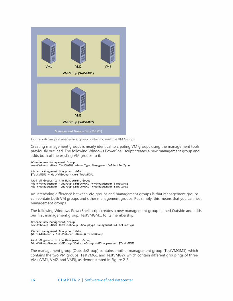
Figure 2-4: Single management group containing multiple VM Groups
Creating management groups is nearly identical to creating VM groups using the management tools
previously outlined. The following Windows PowerShell script creates a new management group and
adds both of the existing VM groups to it:
#Create new Management Group New-VMGroup -Name TestVMGM1 -GroupType ManagementCollectionType #Setup Management Group variable $TestVMGM1 = Get-VMGroup -Name TestVMGM1 #Add VM Groups to the Management Group Add-VMGroupMember -VMGroup $TestVMGM1 -VMGroupMember $TestVMG1 Add-VMGroupMember -VMGroup $TestVMGM1 -VMGroupMember $TestVMG2
An interesting difference between VM groups and management groups is that management groups
can contain both VM groups and other management groups. Put simply, this means that you can nest
management groups.
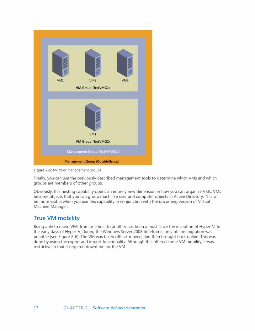
The following Windows PowerShell script creates a new management group named Outside and adds
our first management group, TestVMGM1, to its membership:
#Create new Management Group New-VMGroup -Name OutsideGroup -GroupType ManagementCollectionType #Setup Management Group variable $OutsideGroup = Get-VMGroup -Name OutsideGroup #Add VM groups to the Management Group Add-VMGroupMember -VMGroup $OutsideGroup -VMGroupMember $TestVMGM1
The management group (OutsideGroup) contains another management group (TestVMGM1), which
contains the two VM groups (TestVMG1 and TestVMG2), which contain different groupings of three
VMs (VM1, VM2, and VM3), as demonstrated in Figure 2-5.
17 CHAPTER 2 | Software-defined datacenter
Figure 2-5: Multitier management groups
Finally, you can use the previously described management tools to determine which VMs and which
groups are members of other groups.
Obviously, this nesting capability opens an entirely new dimension in how you can organize VMs. VMs
become objects that you can group much like user and computer objects in Active Directory. This will
be more visible when you use this capability in conjunction with the upcoming version of Virtual
Machine Manager.
True VM mobility
Being able to move VMs from one host to another has been a must since the inception of Hyper-V. In
the early days of Hyper-V, during the Windows Server 2008 timeframe, only offline migration was
possible (see Figure 2-6). The VM was taken offline, moved, and then brought back online. This was
done by using the export and import functionality. Although this offered some VM mobility, it was
restrictive in that it required downtime for the VM.
18 CHAPTER 2 | Software-defined datacenter
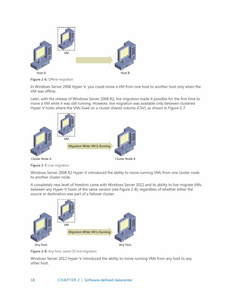
Figure 2-6: Offline migration
In Windows Server 2008 Hyper-V, you could move a VM from one host to another host only when the
VM was offline.
Later, with the release of Windows Server 2008 R2, live migration made it possible for the first time to
move a VM while it was still running. However, live migration was available only between clustered
Hyper-V hosts where the VMs lived on a cluster shared volume (CSV), as shown in Figure 2-7.
Figure 2-7: Live migration
Windows Server 2008 R2 Hyper-V introduced the ability to move running VMs from one cluster node
to another cluster node.
A completely new level of freedom came with Windows Server 2012 and its ability to live-migrate VMs
between any Hyper-V hosts of the same version (see Figure 2-8), regardless of whether either the
source or destination was part of a failover cluster.
Figure 2-8: Any host, same OS live migration
Windows Server 2012 Hyper-V introduced the ability to move running VMs from any host to any
other host.
19 CHAPTER 2 | Software-defined datacenter
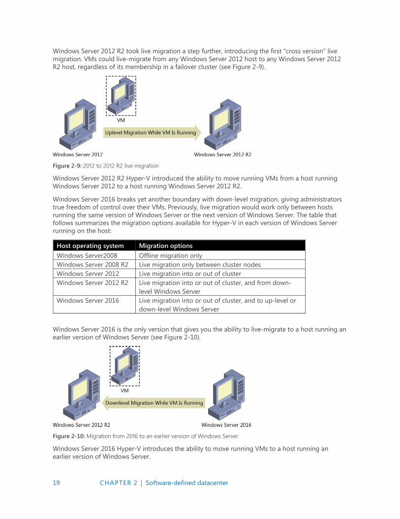
Windows Server 2012 R2 took live migration a step further, introducing the first "cross version" live
migration. VMs could live-migrate from any Windows Server 2012 host to any Windows Server 2012
R2 host, regardless of its membership in a failover cluster (see Figure 2-9).
Figure 2-9: 2012 to 2012 R2 live migration
Windows Server 2012 R2 Hyper-V introduced the ability to move running VMs from a host running
Windows Server 2012 to a host running Windows Server 2012 R2.
Windows Server 2016 breaks yet another boundary with down-level migration, giving administrators
true freedom of control over their VMs. Previously, live migration would work only between hosts
running the same version of Windows Server or the next version of Windows Server. The table that
follows summarizes the migration options available for Hyper-V in each version of Windows Server
running on the host:
Host operating system Migration options
Windows Server2008 Offline migration only
Windows Server 2008 R2 Live migration only between cluster nodes
Windows Server 2012 Live migration into or out of cluster
Windows Server 2012 R2 Live migration into or out of cluster, and from down-
level Windows Server
Windows Server 2016 Live migration into or out of cluster, and to up-level or
down-level Windows Server
Windows Server 2016 is the only version that gives you the ability to live-migrate to a host running an
earlier version of Windows Server (see Figure 2-10).
Figure 2-10: Migration from 2016 to an earlier version of Windows Server
Windows Server 2016 Hyper-V introduces the ability to move running VMs to a host running an
earlier version of Windows Server.
20 CHAPTER 2 | Software-defined datacenter
For VMs on Windows Server 2016 to live-migrate to earlier versions of Windows Server, the following
must be true:
Both hosts must be members of the same Active Directory.
Both hosts must have live-migration functionality turned on.
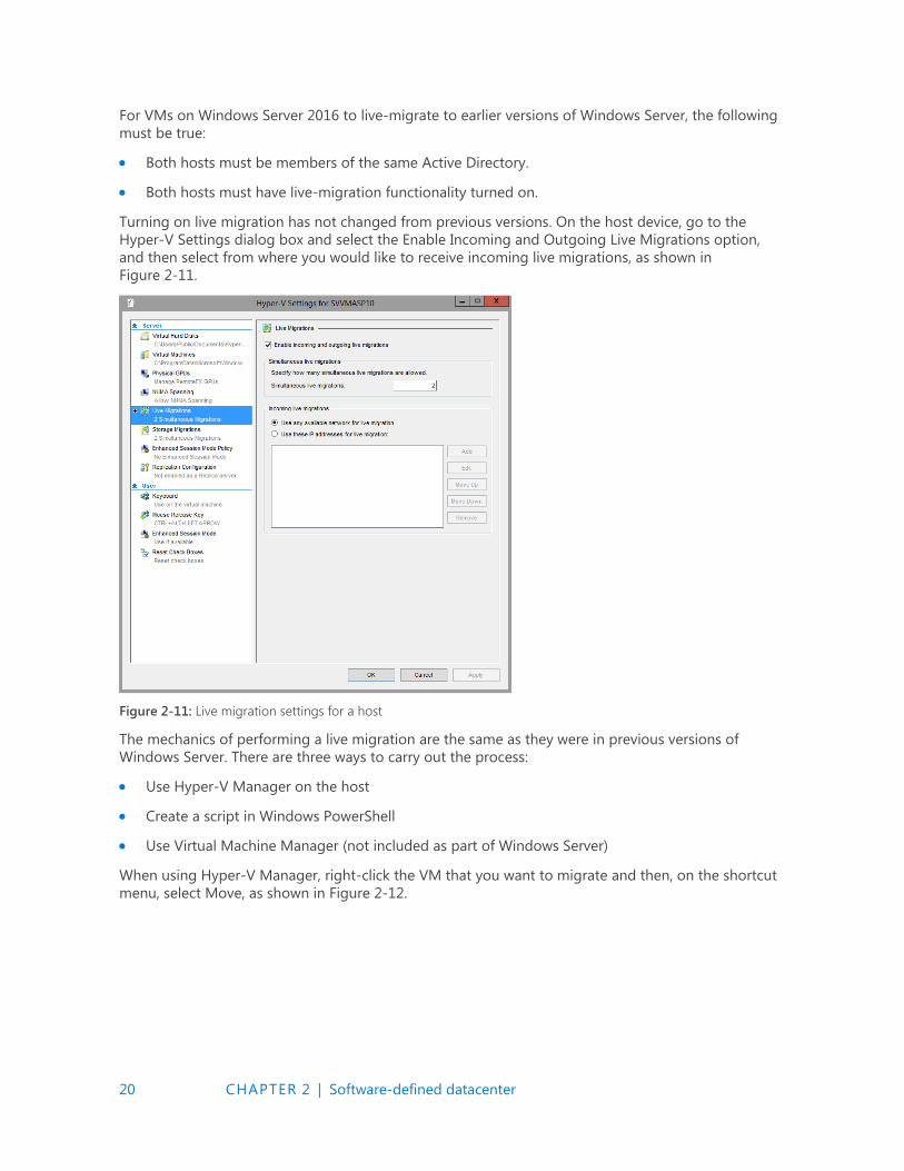
Turning on live migration has not changed from previous versions. On the host device, go to the
Hyper-V Settings dialog box and select the Enable Incoming and Outgoing Live Migrations option,
and then select from where you would like to receive incoming live migrations, as shown in
Figure 2-11.
Figure 2-11: Live migration settings for a host
The mechanics of performing a live migration are the same as they were in previous versions of
Windows Server. There are three ways to carry out the process:
Use Hyper-V Manager on the host
Create a script in Windows PowerShell
Use Virtual Machine Manager (not included as part of Windows Server)
When using Hyper-V Manager, right-click the VM that you want to migrate and then, on the shortcut
menu, select Move, as shown in Figure 2-12.
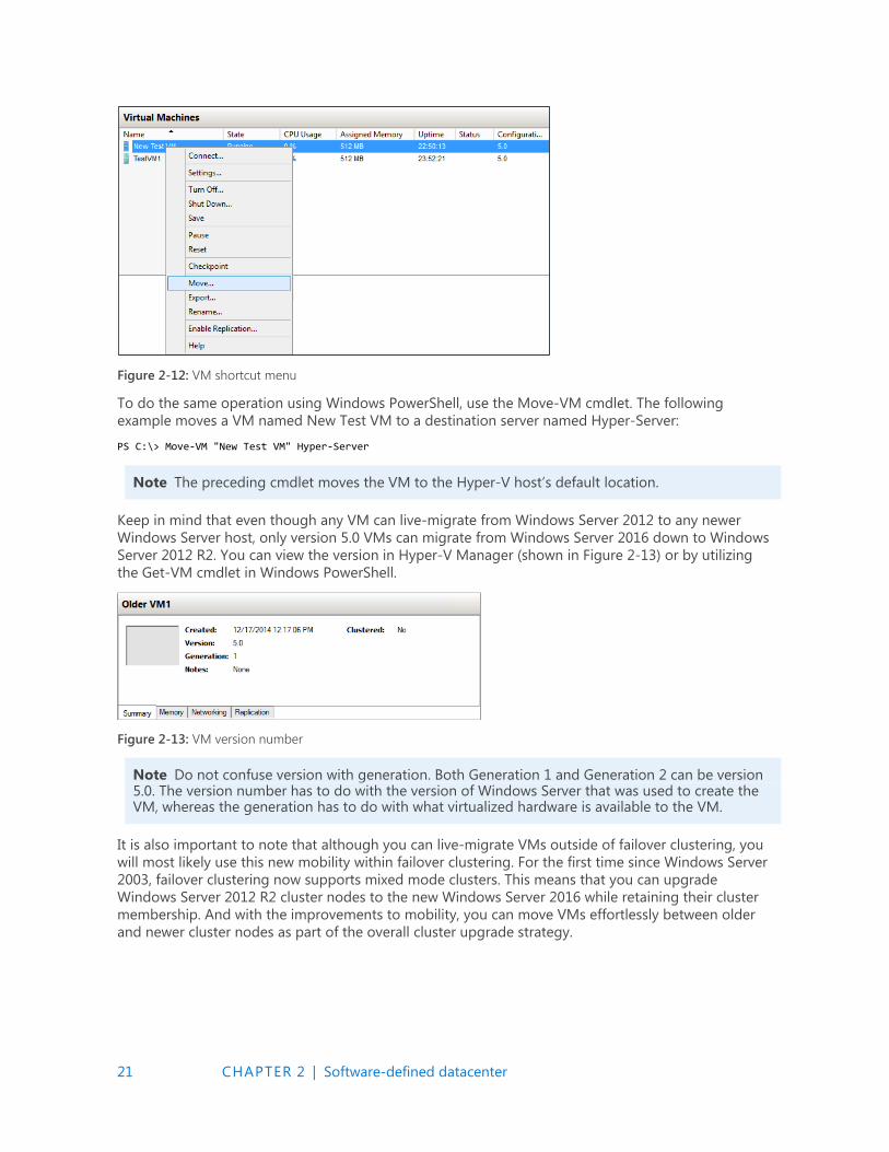
21 CHAPTER 2 | Software-defined datacenter
Figure 2-12: VM shortcut menu
To do the same operation using Windows PowerShell, use the Move-VM cmdlet. The following
example moves a VM named New Test VM to a destination server named Hyper-Server:
PS C:\> Move-VM "New Test VM" Hyper-Server
Note The preceding cmdlet moves the VM to the Hyper-V host’s default location.
Keep in mind that even though any VM can live-migrate from Windows Server 2012 to any newer
Windows Server host, only version 5.0 VMs can migrate from Windows Server 2016 down to Windows
Server 2012 R2. You can view the version in Hyper-V Manager (shown in Figure 2-13) or by utilizing
the Get-VM cmdlet in Windows PowerShell.
Figure 2-13: VM version number
Note Do not confuse version with generation. Both Generation 1 and Generation 2 can be version 5.0. The version number has to do with the version of Windows Server that was used to create the VM, whereas the generation has to do with what virtualized hardware is available to the VM.
It is also important to note that although you can live-migrate VMs outside of failover clustering, you
will most likely use this new mobility within failover clustering. For the first time since Windows Server
2003, failover clustering now supports mixed mode clusters. This means that you can upgrade
Windows Server 2012 R2 cluster nodes to the new Windows Server 2016 while retaining their cluster
membership. And with the improvements to mobility, you can move VMs effortlessly between older
and newer cluster nodes as part of the overall cluster upgrade strategy.

22 CHAPTER 2 | Software-defined datacenter
VM configuration version
The VM upgrade process has changed in Windows Server 2016. In the past, when you imported VMs
to a new version of Hyper-V, they were automatically upgraded. However, it was not always easy to
identify which VMs were imported from a previous version of Hyper-V and which were newly created.
That's because the VM configuration version upgrades automatically with the host upgrade.
The real challenge, however, was that you couldn't roll back the VM to a previous configuration
version. The VM version determines with which versions of Hyper-V the VM’s configuration, saved
state, and snapshot files are compatible. In Windows Server 2016, the VM configuration version
upgrade process is no longer automatic. This makes it possible for you to move the VM to a server
running an earlier version of Hyper-V, such as Windows Server 2012 R2. In that case, you do not have
access to new VM features until you manually update the VM configuration version.
All VM capabilities remain compatible, such as live migration, storage live migration, and dynamic
memory. Hence, upgrading a VM is now a manual operation that is separate from upgrading the
physical host. It is important to note that when you upgrade the configuration version of the VM, you
cannot downgrade it. If you use VMs that were created with Windows Server 2012 R2, you will not
have access to new VM features until you manually update the VM configuration version.
VMs with configuration version 5.0 are compatible with Windows Server 2012 R2 and can run on both
Windows Server 2012 R2 and Windows Server 2016. VMs with configuration version 6.0 are compatible
with Windows Server 2016 but will not run on Hyper-V running on Windows Server 2012 R2.
The following table lists the supported versions of the configuration version on Windows:
Hyper-V host Windows version Supported VM configuration versions
Windows 10 Anniversary Update 8.0, 7.1, 7.0, 6.2, 5.0
Windows Server 2016 Technical Preview 7.1, 7.0, 6.2, 5.0
Windows 10 build 10565 or later 7.0, 6.2, 5.0
Windows 10 builds earlier than 10565 6.2, 5.0
Windows Server 2012 R2 5.0
Windows 8.1 5.0
Upgrading the configuration version
To upgrade the configuration version, shut down the VM and, at an elevated Windows PowerShell
command prompt, type the following command:
Update-VmConfigurationVersion vmname or vmobject.
To check the configuration version of the VMs running on Hyper-V, from an elevated command
prompt, run the following command:
Get-VM * | Format-Table Name, Version
To illustrate the configuration version upgrade process, the following example determines the VM
configuration version imported from a host running Windows Server 2012 R2 and then shows how to
upgrade its configuration version. In this case, as expected, the configuration version of the VM is 5.0
as indicated in Hyper-V Manager (see Figure 2-14).
Figure 2-14: VM version number
23 CHAPTER 2 | Software-defined datacenter
You can confirm this by using Windows PowerShell as follows:
PS C:\Users\Administrator> Get-VM vm02 |Format-Table Name, Version Name Version ---- ------- vm02 5.0
As stated previously, you must shut down the VM and run the following Windows PowerShell
command to upgrade the configuration version of the VM:
PS C:\Users\Administrator> Update-VMConfigurationVersion vm02 Confirm Are you sure you want to perform this action? Performing a configuration version update of "vm02" will prevent it from being migrated to or imported on previous versions of Windows. This operation is not reversible. [Y] Yes [A] Yes to All [N] No [L] No to All [S] Suspend [?] Help (default is "Y"): Y PS C:\Users\Administrator>
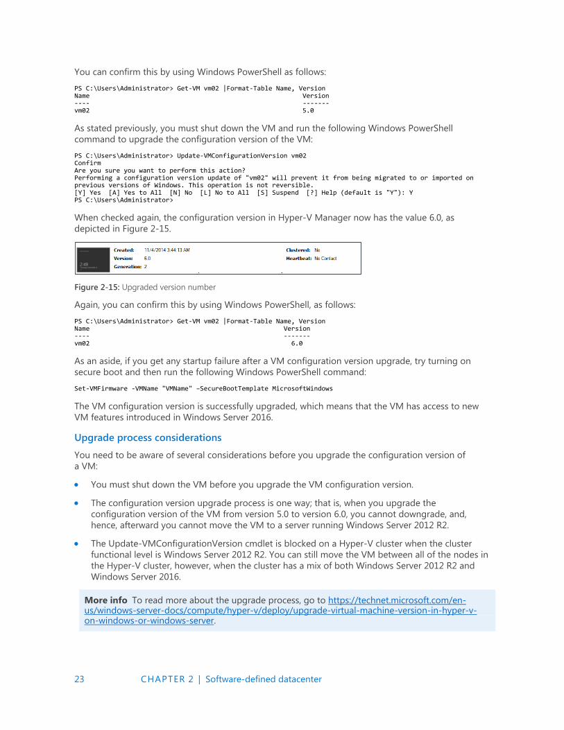
When checked again, the configuration version in Hyper-V Manager now has the value 6.0, as
depicted in Figure 2-15.
Figure 2-15: Upgraded version number
Again, you can confirm this by using Windows PowerShell, as follows:
PS C:\Users\Administrator> Get-VM vm02 |Format-Table Name, Version Name Version ---- ------- vm02 6.0
As an aside, if you get any startup failure after a VM configuration version upgrade, try turning on
secure boot and then run the following Windows PowerShell command:
Set-VMFirmware -VMName "VMName" –SecureBootTemplate MicrosoftWindows
The VM configuration version is successfully upgraded, which means that the VM has access to new
VM features introduced in Windows Server 2016.
Upgrade process considerations
You need to be aware of several considerations before you upgrade the configuration version of
a VM:
You must shut down the VM before you upgrade the VM configuration version.
The configuration version upgrade process is one way; that is, when you upgrade the
configuration version of the VM from version 5.0 to version 6.0, you cannot downgrade, and,
hence, afterward you cannot move the VM to a server running Windows Server 2012 R2.
The Update-VMConfigurationVersion cmdlet is blocked on a Hyper-V cluster when the cluster
functional level is Windows Server 2012 R2. You can still move the VM between all of the nodes in
the Hyper-V cluster, however, when the cluster has a mix of both Windows Server 2012 R2 and
Windows Server 2016.
More info To read more about the upgrade process, go to https://technet.microsoft.com/en-us/windows-server-docs/compute/hyper-v/deploy/upgrade-virtual-machine-version-in-hyper-v-on-windows-or-windows-server.
24 CHAPTER 2 | Software-defined datacenter
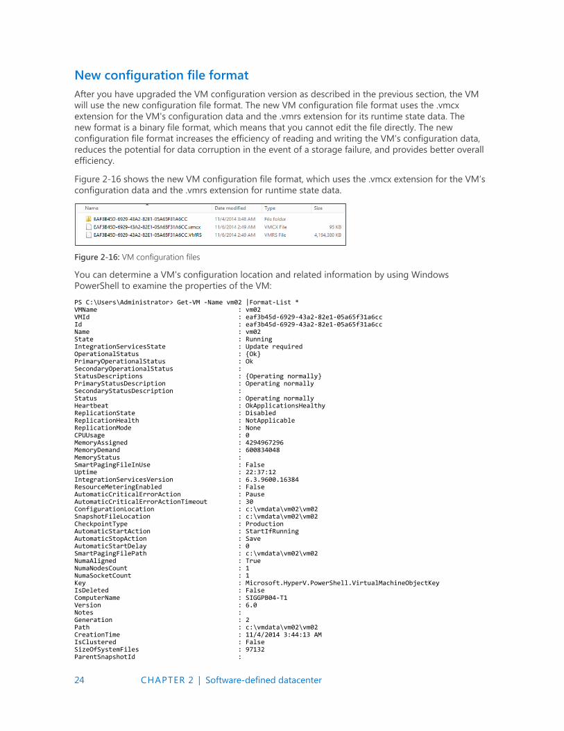
New configuration file format
After you have upgraded the VM configuration version as described in the previous section, the VM
will use the new configuration file format. The new VM configuration file format uses the .vmcx
extension for the VM's configuration data and the .vmrs extension for its runtime state data. The
new format is a binary file format, which means that you cannot edit the file directly. The new
configuration file format increases the efficiency of reading and writing the VM's configuration data,
reduces the potential for data corruption in the event of a storage failure, and provides better overall
efficiency.
Figure 2-16 shows the new VM configuration file format, which uses the .vmcx extension for the VM’s
configuration data and the .vmrs extension for runtime state data.
Figure 2-16: VM configuration files
You can determine a VM's configuration location and related information by using Windows
PowerShell to examine the properties of the VM:
PS C:\Users\Administrator> Get-VM -Name vm02 |Format-List * VMName : vm02 VMId : eaf3b45d-6929-43a2-82e1-05a65f31a6cc Id : eaf3b45d-6929-43a2-82e1-05a65f31a6cc Name : vm02 State : Running IntegrationServicesState : Update required OperationalStatus : {Ok} PrimaryOperationalStatus : Ok SecondaryOperationalStatus : StatusDescriptions : {Operating normally} PrimaryStatusDescription : Operating normally SecondaryStatusDescription : Status : Operating normally Heartbeat : OkApplicationsHealthy ReplicationState : Disabled ReplicationHealth : NotApplicable ReplicationMode : None CPUUsage : 0 MemoryAssigned : 4294967296 MemoryDemand : 600834048 MemoryStatus : SmartPagingFileInUse : False Uptime : 22:37:12 IntegrationServicesVersion : 6.3.9600.16384 ResourceMeteringEnabled : False AutomaticCriticalErrorAction : Pause AutomaticCriticalErrorActionTimeout : 30 ConfigurationLocation : c:\vmdata\vm02\vm02 SnapshotFileLocation : c:\vmdata\vm02\vm02 CheckpointType : Production AutomaticStartAction : StartIfRunning AutomaticStopAction : Save AutomaticStartDelay : 0 SmartPagingFilePath : c:\vmdata\vm02\vm02 NumaAligned : True NumaNodesCount : 1 NumaSocketCount : 1 Key : Microsoft.HyperV.PowerShell.VirtualMachineObjectKey IsDeleted : False ComputerName : SIGGPB04-T1 Version : 6.0 Notes : Generation : 2 Path : c:\vmdata\vm02\vm02 CreationTime : 11/4/2014 3:44:13 AM IsClustered : False SizeOfSystemFiles : 97132 ParentSnapshotId :
25 CHAPTER 2 | Software-defined datacenter
ParentSnapshotName : MemoryStartup : 4294967296 DynamicMemoryEnabled : False MemoryMinimum : 536870912 MemoryMaximum : 1099511627776 ProcessorCount : 1 RemoteFxAdapter : NetworkAdapters : {Network Adapter} FibreChannelHostBusAdapters : {} ComPort1 : Microsoft.HyperV.PowerShell.VMComPort ComPort2 : Microsoft.HyperV.PowerShell.VMComPort FloppyDrive : DVDDrives : {} HardDrives : {Hard Drive on SCSI controller number 0 at location 0} VMIntegrationService : {Time Synchronization, Heartbeat, Key-Value Pair Exchange, Shutdown...}
Production checkpoints
Windows Server 2016 introduces a new concept of taking checkpoints for production VMs; that is,
production checkpoints. A checkpoint is a point-in-time capture of the state of a VM, which gives you
the ability to revert the VM to an earlier state. Before Windows Server 2016, the use of checkpoints
focused on test and development scenarios but was not recommended for use in production
environments.
Production checkpoints deliver the same kind of experience as in Windows Server 2012 R2, but they
are now fully supported for production environments for two main reasons:
The Volume Snapshot Service (VSS) is now used instead of saved state to create checkpoints.
Restoring a checkpoint is just like restoring a system backup.
Note VSS is used for creating production checkpoints only on Windows VMs; Linux VMs do this by flushing their file system buffers to create a file system–consistent checkpoint.
If you want to create checkpoints by using saved-state technology, you can still use standard checkpoints for your VM. However, the default for new VMs will be to create production checkpoints with a fallback to standard checkpoints.
In certain scenarios, an administrator might need to disable checkpoints for specific VMs for
operational reasons. This is now feasible in Windows Server 2016, which gives you the ability to turn
on or turn off production checkpoints on individual VMs. This option provides flexibility and gives
Hyper-V administrators the means to manage and optimize their resources effectively.
Figure 2-17 demonstrates how you can use VM settings to turn on or turn off checkpoints for the
VM and allow production checkpoints. By default, the Enable Checkpoints option is selected and is
configured to allow production checkpoints and to create standard checkpoints if it is not possible
to create a production checkpoint.
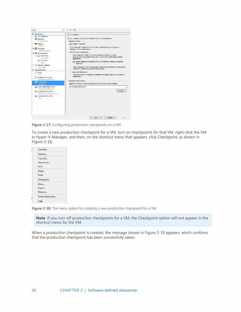
26 CHAPTER 2 | Software-defined datacenter
Figure 2-17: Configuring production checkpoints on a VM
To create a new production checkpoint for a VM, turn on checkpoints for that VM, right-click the VM
in Hyper-V Manager, and then, on the shortcut menu that appears, click Checkpoint, as shown in
Figure 2-18.
Figure 2-18: The menu option for creating a new production checkpoint for a VM
Note If you turn off production checkpoints for a VM, the Checkpoint option will not appear in the shortcut menu for the VM.
When a production checkpoint is created, the message shown in Figure 2-19 appears, which confirms
that the production checkpoint has been successfully taken.

27 CHAPTER 2 | Software-defined datacenter
Figure 2-19: Message indicating that the production checkpoint was successfully created
And, of course, you also can do all of this by using Windows PowerShell.
Hot add and hot remove for network adapters and memory
With Windows Server 2016, you no longer need to plan for downtime to upgrade or downgrade
memory on VMs hosted on Hyper-V. There is also no downtime when adding or removing a network
card. Now, you can hot-add and hot-remove both network adapters and memory on the platform.
This is a huge improvement that will ease the Hyper-V administrator’s job. In a physical environment,
installing additional RAM or adding a new network card is a time-consuming process that usually
involves planning and downtime. With this new feature, you can accomplish everything with no
downtime. Both service providers and enterprises can now scale up or scale down the memory of VMs
in seconds by using either Hyper-V Manager or Windows PowerShell.
Note Hot-add memory works for Generation 1 and Generation 2 guests running Windows Server 2016. It does not work with Windows Server 2012 R2 or earlier.
Hot add and remove memory
Figure 2-20 presents Hyper-V Manager with two VMs named VM1 and VM2 running on it. Hyper-V
Manager shows that VM2 is a Generation 1 VM, and the Settings dialog box for VM2 shows that this
VM has been provisioned with 2 GB (2,048 MB) of RAM.
Figure 2-20: Generation 1 settings for memory

28 CHAPTER 2 | Software-defined datacenter
Connecting to this VM using Virtual Machine Connection shows that two applications are currently
running on its desktop: Date and Time, which displays a clock with the current time, and Task
Manager, which displays the memory usage of VM2 and shows that 2 GB are available, as shown
in Figure 2-21.
Figure 2-21: VM task manager showing memory usage
Use the settings for VM2 to change the RAM used by this VM from 2 GB to 4 GB and then click Apply
while the VM is still running. Within a few seconds, Hyper-V Manager shows that VM2 is now running
with 4 GB of RAM, with no reboot necessary, as illustrated in Figure 2-22.
Figure 2-22 VM memory settings changing while running
Virtual Machine Connection shows that the clock is still running in VM2, and Task Manager displays
4 GB of memory available to the VM, using the hot-add memory feature of Windows Server 2016, as
shown in Figure 2-23.
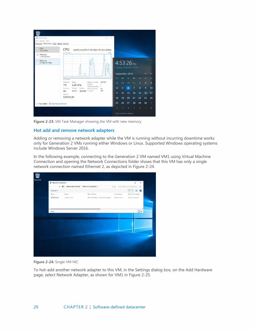
29 CHAPTER 2 | Software-defined datacenter
Figure 2-23: VM Task Manager showing the VM with new memory
Hot add and remove network adapters
Adding or removing a network adapter while the VM is running without incurring downtime works
only for Generation 2 VMs running either Windows or Linux. Supported Windows operating systems
include Windows Server 2016.
In the following example, connecting to the Generation 2 VM named VM1 using Virtual Machine
Connection and opening the Network Connections folder shows that this VM has only a single
network connection named Ethernet 2, as depicted in Figure 2-24.
Figure 2-24: Single VM NIC
To hot-add another network adapter to this VM, in the Settings dialog box, on the Add Hardware
page, select Network Adapter, as shown for VM1 in Figure 2-25.
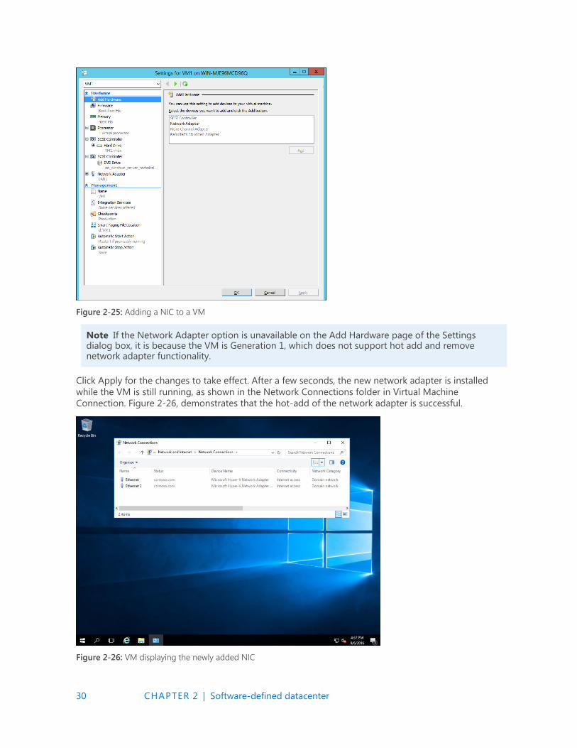
30 CHAPTER 2 | Software-defined datacenter
Figure 2-25: Adding a NIC to a VM
Note If the Network Adapter option is unavailable on the Add Hardware page of the Settings dialog box, it is because the VM is Generation 1, which does not support hot add and remove network adapter functionality.
Click Apply for the changes to take effect. After a few seconds, the new network adapter is installed
while the VM is still running, as shown in the Network Connections folder in Virtual Machine
Connection. Figure 2-26, demonstrates that the hot-add of the network adapter is successful.
Figure 2-26: VM displaying the newly added NIC
31 CHAPTER 2 | Software-defined datacenter
Failover cluster
By John Marlin and Colin Robinson
This section describes key improvements Microsoft has made to failover clustering in Windows Server
2016. These improvements include the following:
Cloud witness using Microsoft Azure
Shared VHDX improvements
Improved cluster logs
Active memory dumps
Network name diagnostics
Cluster operating system rolling upgrade
Workgroup and multidomain clusters
SMB multichannel and multi-NIC cluster networks
VM improvements
In addition, Colin Robinson walks us through a detailed demonstration of performing a rolling
upgrade on a failover cluster.
Creating a cloud witness by using Azure
Beginning with Windows Server 2008, each version of failover clustering introduced a new quorum
type to complement what already exists. That hasn't changed. Windows Server 2016 introduces the
cloud witness quorum type, a witness that you can create in the cloud by using Azure.
This quorum type takes advantage of the Azure public cloud as the arbitration (witness) point for the
cluster. You can achieve this configuration without the need for an extra site and you will utilize it
mostly in multisite clusters. It provides a quorum option for the following situations:
Multisite clusters that do not have a third site on which to place a file-share witness
Clusters using nonshared storage
Guest clusters hosted in Azure
Guest clusters hosted in private clouds
Clusters using Direct-Attached Storage (DAS)
The cloud witness acts the same as a file-share witness, using the same basic logic in that it does not
contain a copy of the cluster database and will act as a deciding vote to prevent split brains (multiple
nodes running in the same cluster that cannot communicate with one another).
To configure a cloud witness, you first must have an Azure subscription. Here are the steps you need
to take to get one:
1. Sign in to the Azure management portal (https://portal.azure.com and create a storage account
for this witness (if you are not sure how to see https://azure.microsoft.com/documentation/
articles/storage-create-storage-account/)

32 CHAPTER 2 | Software-defined datacenter
2. When the storage account is created, highlight it in the portal, and then click Manage Access
Keys. Copy the primary access key for later use.
3. In the Failover Cluster Manager console, configure the quorum for the cloud witness. First, right-
click the name of the cluster, and then, on the shortcut menu that opens, click More Actions, and
then select Configure Cluster Quorum Settings, as demonstrated in Figure 2-27.
Figure 2-27: Configuring cluster quorum settings
4. The Configure Cluster Quorum Wizard opens. On the Select Quorum Configuration Option page,
click Select The Quorum Witness, as depicted in Figure 2-3
Figure 2-28: Selecting the quorum type
5. On the Select Quorum Witness page, click Configure A Cloud Witness, as illustrated in
Figure 2-29.
Figure 2-29: Configuring a cloud witness
6. On the Configure Cloud Witness page, type the storage account name you created in the
management portal, your Azure primary storage account key, and the Azure service endpoint,
as shown in Figure 2-30.
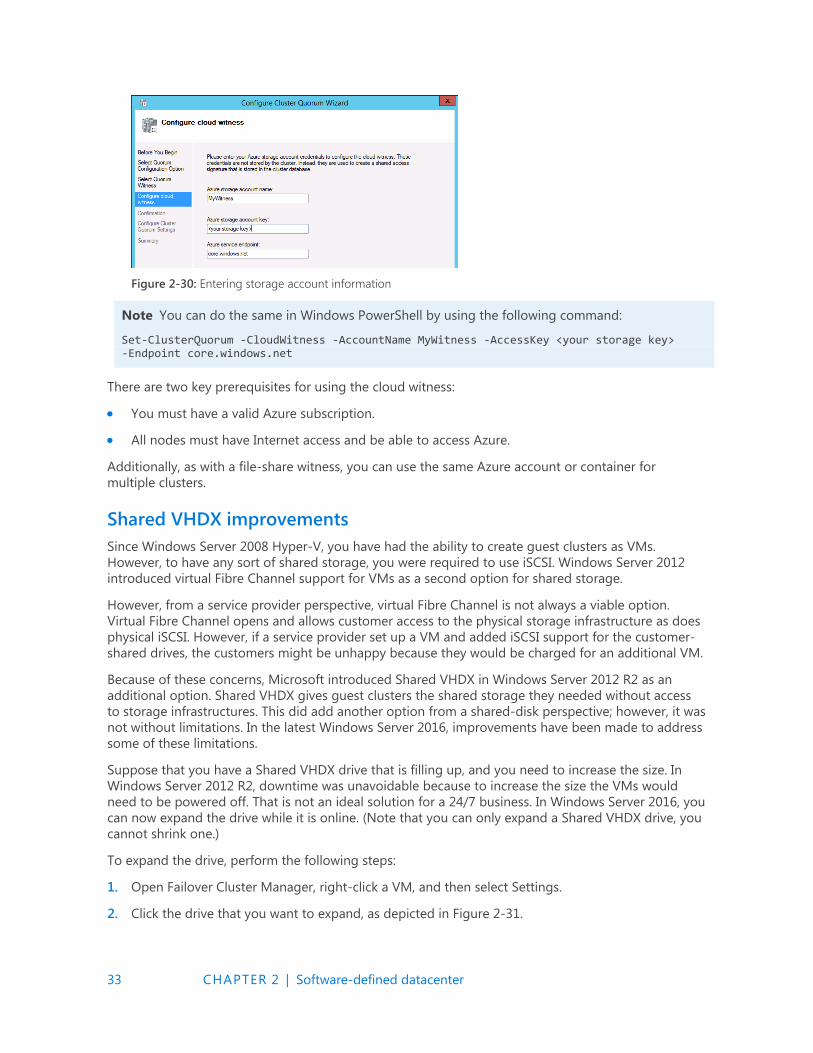
33 CHAPTER 2 | Software-defined datacenter
Figure 2-30: Entering storage account information
Note You can do the same in Windows PowerShell by using the following command:
Set-ClusterQuorum -CloudWitness -AccountName MyWitness -AccessKey <your storage key> -Endpoint core.windows.net
There are two key prerequisites for using the cloud witness:
You must have a valid Azure subscription.
All nodes must have Internet access and be able to access Azure.
Additionally, as with a file-share witness, you can use the same Azure account or container for
multiple clusters.
Shared VHDX improvements
Since Windows Server 2008 Hyper-V, you have had the ability to create guest clusters as VMs.
However, to have any sort of shared storage, you were required to use iSCSI. Windows Server 2012
introduced virtual Fibre Channel support for VMs as a second option for shared storage.
However, from a service provider perspective, virtual Fibre Channel is not always a viable option.
Virtual Fibre Channel opens and allows customer access to the physical storage infrastructure as does
physical iSCSI. However, if a service provider set up a VM and added iSCSI support for the customer-
shared drives, the customers might be unhappy because they would be charged for an additional VM.
Because of these concerns, Microsoft introduced Shared VHDX in Windows Server 2012 R2 as an
additional option. Shared VHDX gives guest clusters the shared storage they needed without access
to storage infrastructures. This did add another option from a shared-disk perspective; however, it was
not without limitations. In the latest Windows Server 2016, improvements have been made to address
some of these limitations.
Suppose that you have a Shared VHDX drive that is filling up, and you need to increase the size. In
Windows Server 2012 R2, downtime was unavoidable because to increase the size the VMs would
need to be powered off. That is not an ideal solution for a 24/7 business. In Windows Server 2016, you
can now expand the drive while it is online. (Note that you can only expand a Shared VHDX drive, you
cannot shrink one.)
To expand the drive, perform the following steps:
1. Open Failover Cluster Manager, right-click a VM, and then select Settings.
2. Click the drive that you want to expand, as depicted in Figure 2-31.
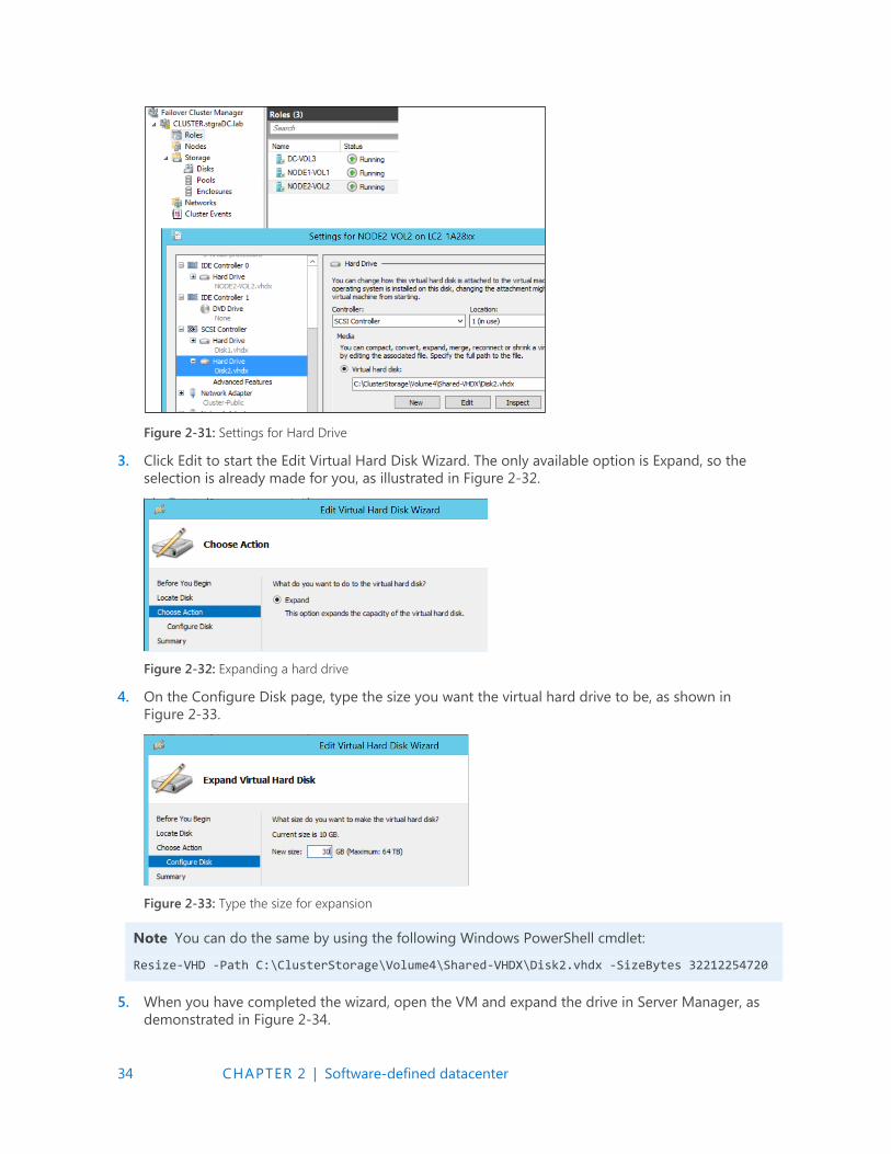
34 CHAPTER 2 | Software-defined datacenter
Figure 2-31: Settings for Hard Drive
3. Click Edit to start the Edit Virtual Hard Disk Wizard. The only available option is Expand, so the
selection is already made for you, as illustrated in Figure 2-32.
Figure 2-32: Expanding a hard drive
4. On the Configure Disk page, type the size you want the virtual hard drive to be, as shown in
Figure 2-33.
Figure 2-33: Type the size for expansion
Note You can do the same by using the following Windows PowerShell cmdlet:
Resize-VHD -Path C:\ClusterStorage\Volume4\Shared-VHDX\Disk2.vhdx -SizeBytes 32212254720
5. When you have completed the wizard, open the VM and expand the drive in Server Manager, as
demonstrated in Figure 2-34.

35 CHAPTER 2 | Software-defined datacenter
Figure 2-34: Extending a volume in Server manager
With your VMs all running on your Hyper-V cluster, it is time to back up the machines. In Windows
Server 2012 R2, you cannot back up the Shared VHDX attached to a VM from the host. Because it is
shared, it is blocked from being backed up. However, in Windows Server 2016, you can select it as a
virtual hard drive (VHD) to back up.
VMs that include a Shared VHDX can now also participate in Hyper-V Replica. In previous versions of
Windows Server, VMs with a Shared VHDX were blocked from participating. With the improvements in
Shared VHDX, you not only have the option to replicate the VMs, you also have the option to select
any or all of the Shared VHDX drives, as presented in Figure 2-35.
Figure 2-35: Choosing replica VHDs
Improved cluster logs
Getting as much critical data as possible in a timely fashion can help to quickly resolve failover
clustering problems. Getting the right data at the right time can be critical for restoring services. With
all the Service-Level Agreements (SLAs) available, the right diagnostics is crucial to many businesses.
From a diagnostic standpoint, the first improvement in Windows Server 2016 is with the cluster
diagnostics log. The cluster log has always been useful for identifying an error, what led to an error,
what was happening at the time of the error, and so on. But using the cluster log to determine things
such as the configuration of the cluster is a more involved process.
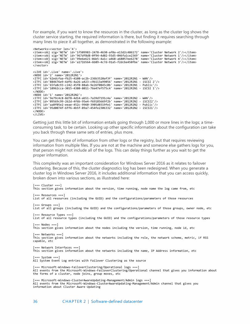
36 CHAPTER 2 | Software-defined datacenter
For example, if you want to know the resources in the cluster, as long as the cluster log shows the
cluster service starting, the required information is there, but finding it requires searching through
many lines to piece it all together, as demonstrated in the following example:
<Networks><vector len='4'> <item><obj sig='NETW' id='1f509983-2478-4630-af8a-e13d2c486172' name='Cluster Network 2'/></item> <item><obj sig='NETW' id='967df8d8-0f94-4d02-93d5-046fa1ce2369' name='Cluster Network 1'/></item> <item><obj sig='NETW' id='99e6e621-0de5-4a1c-a468-a68057ee6278' name='Cluster Network 4'/></item> <item><obj sig='NETW' id='a171b564-6b89-4c7d-91a5-f2dcbe450fbe' name='Cluster Network 3'/></item> </vector> <LIVE id='.Live' name='.Live'> <NODE id='2' name='2012R2N1'> <ITFC id='62edcfaa-fb25-4108-ac2b-236b3520af3f' name='2012R2N1 - WAN'/> <ITFC id='884676e9-6df6-4a26-a423-c9b113a99056' name='2012R2N1 - iSCSI 2'/> <ITFC id='65fa8c93-c242-45f0-88ab-9e26f0845c0b' name='2012R2N1 - Public'/> <ITFC id='10962cca-3015-4380-8011-76e47ef575c4' name='2012R2N1 - iSCSI 1'/> </NODE> <NODE id='1' name='2012R2N2'> <ITFC id='9e79c4c8-8d78-4d14-ab51-7a39d7191c4a' name='2012R2N2 - WAN'/> <ITFC id='09569c99-262d-4f6b-95e4-f69185669f2b' name='2012R2N2 - iSCSI2'/> <ITFC id='aa8f05e2-eeae-452c-9960-3905d0319fe1' name='2012R2N2 - Public'/> <ITFC id='95d0074f-6ff6-4b5f-89a7-454fe2306332' name='2012R2N2 - iSCSI1'/> </NODE> </LIVE>
Getting just this little bit of information entails going through 1,000 or more lines in the logs; a time-
consuming task, to be certain. Looking up other specific information about the configuration can take
you back through these same sets of entries, plus more.
You can get this type of information from other logs or the registry, but that requires reviewing
information from multiple files. If you are not at the machine and someone else gathers logs for you,
that person might not include all of the logs. This can delay things further as you wait to get the
proper information.
This complexity was an important consideration for Windows Server 2016 as it relates to failover
clustering. Because of this, the cluster diagnostics log has been redesigned. When you generate a
cluster log in Windows Server 2016, it includes additional information that you can access quickly,
broken down into various sections, as illustrated here:
[=== Cluster ===] This section gives information about the version, time running, node name the log came from, etc [=== Resources ===] List of all resources (including the GUID) and the configurations/parameters of those resources [=== Groups ===] List of all groups (including the GUID) and the configurations/parameters of those groups, owner node, etc [=== Resource Types ===] List of all resource types (including the GUID) and the configurations/parameters of those resource types [=== Nodes ===] This section gives information about the nodes including the version, time running, node id, etc [=== Networks ===] This section gives information about the networks including the role, the network scheme, metric, if RSS capable, etc [=== Network Interfaces ===] This section gives information about the networks including the name, IP Address information, etc [=== System ===] All System Event Log entries with Failover Clustering as the source [=== Microsoft-Windows-FailoverClustering/Operational logs ===] All events from the Microsoft-Windows-FailoverClustering/Operational channel that gives you information about the forms of a cluster, node joins, group moves, etc [=== Microsoft-Windows-ClusterAwareUpdating-Management/Admin logs ===] All events from the Microsoft-Windows-ClusterAwareUpdating-Management/Admin channel that gives you information about Cluster Aware Updating

37 CHAPTER 2 | Software-defined datacenter
[=== Microsoft-Windows-ClusterAwareUpdating/Admin logs ===] All events from the Microsoft-Windows-ClusterAwareUpdating/Admin channel that gives you information about Cluster Aware Updating [=== Microsoft-Windows-FailoverClustering/DiagnosticVerbose ===] This is actually a new event channel that gives you the similar output as Debug Level 5 for a Cluster Log without having to set it. You can use this information to get deeper into the calls and goings on with the cluster and gives it in a more verbose output. [=== Cluster Logs ===] This is the output that you normally see in a cluster log.
Clearly, there is a lot to this log now. Using this one log can reduce the time you spend looking for
information or trying to resolve an issue. Instead of having to review three or more files that might be
loaded in three different applications with their own formats, you now need only review one file.
The other useful thing about the log is that if you generate it with no switches, everything in an event
channel (for example, the System Event) is shown. So you can actually get any history pertaining to a
particular problem. For cases in which you can reproduce an error condition and do not need all of
the history, you can generate a log for the last five minutes (TimeSpan=5). Helpfully, the new cluster log
uses this same five-minute time span for all of the event channels and gives you only those, so you
don’t need to deal with an unnecessarily large file.
Active memory dump
Another new feature as it relates to diagnostics is the ability to capture memory dumps. Imagine that
you have a big Hyper-V cluster and each of the nodes has 512 GB of memory. If the node is having an
issue and you create a memory dump that contains both user and kernel mode memory, that memory
dump is going to be larger than 512 GB. Trying to work with a file that size can be a nightmare. First,
you need to ensure that you have a drive with enough free space to hold a file of that size. You then
need to spend hours zipping, uploading, and unzipping before you can even begin to open it. If the
problem is with the host server itself and you are running VMs that use 500 GB of that memory, this is
information that you don’t need, because it does not pertain to the host.
Because of this, there is a new dump setting called Active Memory Dump. This setting captures only
the memory that the host is actually using. If the host is actively using only 5 GB of memory, a 5 GB
memory dump is what will be created. This smaller dump is much easier to parse than the 512 GB file
in the previous scenario.
The Active Memory Dump option is in the same location as the normal dump settings, in the Startup
And Recovery dialog box of the System Properties, as shown in Figure 2-36.
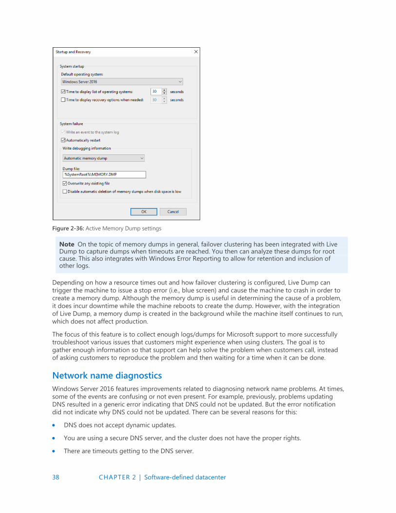
38 CHAPTER 2 | Software-defined datacenter
Figure 2-36: Active Memory Dump settings
Note On the topic of memory dumps in general, failover clustering has been integrated with Live Dump to capture dumps when timeouts are reached. You then can analyze these dumps for root cause. This also integrates with Windows Error Reporting to allow for retention and inclusion of other logs.
Depending on how a resource times out and how failover clustering is configured, Live Dump can
trigger the machine to issue a stop error (i.e., blue screen) and cause the machine to crash in order to
create a memory dump. Although the memory dump is useful in determining the cause of a problem,
it does incur downtime while the machine reboots to create the dump. However, with the integration
of Live Dump, a memory dump is created in the background while the machine itself continues to run,
which does not affect production.
The focus of this feature is to collect enough logs/dumps for Microsoft support to more successfully
troubleshoot various issues that customers might experience when using clusters. The goal is to
gather enough information so that support can help solve the problem when customers call, instead
of asking customers to reproduce the problem and then waiting for a time when it can be done.
Network name diagnostics
Windows Server 2016 features improvements related to diagnosing network name problems. At times,
some of the events are confusing or not even present. For example, previously, problems updating
DNS resulted in a generic error indicating that DNS could not be updated. But the error notification
did not indicate why DNS could not be updated. There can be several reasons for this:
DNS does not accept dynamic updates.
You are using a secure DNS server, and the cluster does not have the proper rights.
There are timeouts getting to the DNS server.

39 CHAPTER 2 | Software-defined datacenter
Troubleshooting an event such as this took time because you had to look at it in broad terms before
you could focus on a specific area and narrow down the problem. In Windows Server 2016, events are
updated to include the specific error. So, if the error is due to one of the reasons mentioned in the list,
you are notified of the error and can immediately focus on that one cause. This makes for quicker
resolutions because you do not need to troubleshoot a problem that does not exist.
Also, additional checks have been added for the network name to help prevent a problem that might
not occur for days or weeks. During every online/offline of the resource and every one hour that the
name is online, Windows Server 2016 checks for the following:
A searchable domain controller
A synchronized Cluster Name Object (CNO) password
A CNO in Active Directory that is turned on
An existing CNO and Virtual Computer Object (VCO) in Active Directory
Windows Server 2016 also includes several additional tests in cluster validation for network names to
do the following:
Check that the CNO and VCO are greater than 15 characters
Verify that the CNO has Create Computer Object permissions in the Organizational Unit (OU) in
the Active Directory of which it is a member
Ensure that it is possible to sign in to the CNO and corresponding VCO
Confirm that the local Users group on the nodes has the members CLISUR and NT
AUTHORITY\Authenticated Users
The previous items are commonly the cause of issues with network names, which is why these new
diagnostics were added.
Cluster operating system rolling upgrade
Windows Server 2016 introduces a wonderful new method for upgrading the operating system of
your server clusters with no downtime and dramatically reduced effort. This feature is called the
cluster operating system rolling upgrade. Cluster operating system rolling upgrades initially will be
limited to Hyper-V clusters and scale-out file servers (SOFS) clusters for Windows Server 2016.
Until now, the cluster administrator was tasked with developing a detailed migration plan to update
clusters with a new operating system. Often, administrators waited to move a cluster until new
hardware was brought in as part of a system refresh. This often meant several years without any new
capabilities for the cluster as well as some planned downtime for moving services between the old
and new cluster.
Cluster operating system rolling upgrade does not require the purchase of any additional hardware;
the upgrades are done in place to each of the nodes. The cluster itself never needs to be stopped or
restarted; the work takes place at the cluster node level, and all services remain online during the
rolling upgrade process. Unlike typical cluster migration strategies, you do not need to make a new
cluster. The existing cluster objects, including cluster name and cluster IPs, remain the same and
online during the upgrade. Even better news is that you can fully reverse the process until the Cluster
Functional Level attribute is changed. (More on that later.)
Figure 2-37 shows a three-node Hyper-V cluster named ContosoPVTCloud.
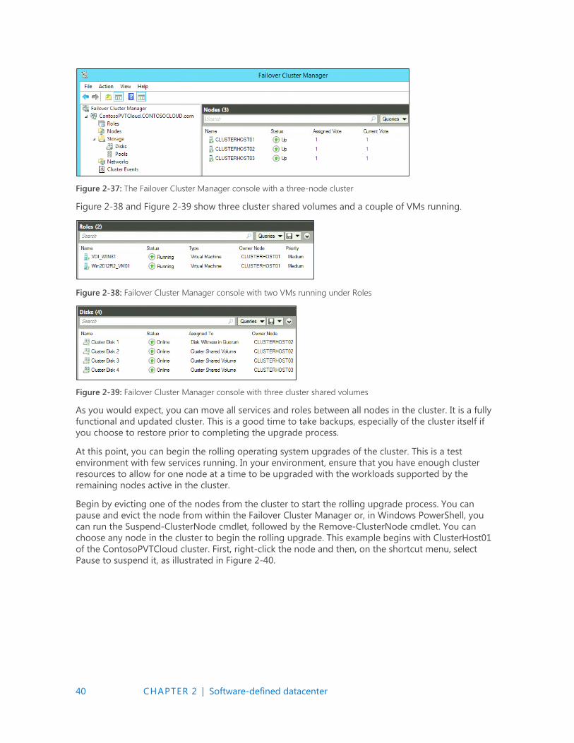
40 CHAPTER 2 | Software-defined datacenter
Figure 2-37: The Failover Cluster Manager console with a three-node cluster
Figure 2-38 and Figure 2-39 show three cluster shared volumes and a couple of VMs running.
Figure 2-38: Failover Cluster Manager console with two VMs running under Roles
Figure 2-39: Failover Cluster Manager console with three cluster shared volumes
As you would expect, you can move all services and roles between all nodes in the cluster. It is a fully
functional and updated cluster. This is a good time to take backups, especially of the cluster itself if
you choose to restore prior to completing the upgrade process.
At this point, you can begin the rolling operating system upgrades of the cluster. This is a test
environment with few services running. In your environment, ensure that you have enough cluster
resources to allow for one node at a time to be upgraded with the workloads supported by the
remaining nodes active in the cluster.
Begin by evicting one of the nodes from the cluster to start the rolling upgrade process. You can
pause and evict the node from within the Failover Cluster Manager or, in Windows PowerShell, you
can run the Suspend-ClusterNode cmdlet, followed by the Remove-ClusterNode cmdlet. You can
choose any node in the cluster to begin the rolling upgrade. This example begins with ClusterHost01
of the ContosoPVTCloud cluster. First, right-click the node and then, on the shortcut menu, select
Pause to suspend it, as illustrated in Figure 2-40.
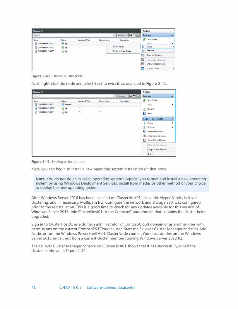
41 CHAPTER 2 | Software-defined datacenter
Figure 2-40: Pausing cluster node
Next, right-click the node and select Evict to evict it, as depicted in Figure 2-41.
Figure 2-41: Evicting a cluster node
Next, you can begin to install a new operating system installation on that node.
Note You do not do an in-place operating system upgrade; you format and install a new operating system by using Windows Deployment Services, install from media, or other method of your choice to deploy the new operating system.
After Windows Server 2016 has been installed on ClusterHost01, install the Hyper-V role, failover
clustering, and, if necessary, Multipath I/O. Configure the network and storage as it was configured
prior to the reinstallation. This is a good time to check for any updates available for this version of
Windows Server 2016. Join ClusterHost01 to the ContosoCloud domain that contains the cluster being
upgraded.
Sign in to ClusterHost01 as a domain administrator of ContosoCloud domain or as another user with
permissions on the current ContosoPVTCloud cluster. Start the Failover Cluster Manager and click Add
Node, or run the Windows PowerShell Add-ClusterNode cmdlet. You must do this on the Windows
Server 2016 server, not from a current cluster member running Windows Server 2012 R2.
The Failover Cluster Manager console on ClusterHost01 shows that it has successfully joined the
cluster, as shown in Figure 2-42.
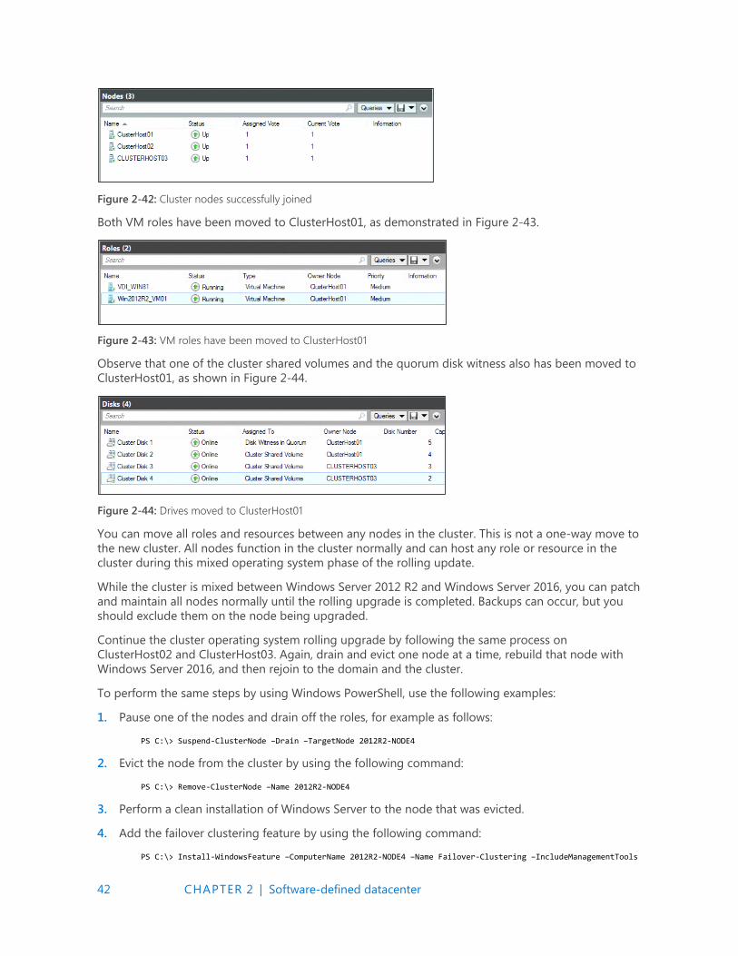
42 CHAPTER 2 | Software-defined datacenter
Figure 2-42: Cluster nodes successfully joined
Both VM roles have been moved to ClusterHost01, as demonstrated in Figure 2-43.
Figure 2-43: VM roles have been moved to ClusterHost01
Observe that one of the cluster shared volumes and the quorum disk witness also has been moved to
ClusterHost01, as shown in Figure 2-44.
Figure 2-44: Drives moved to ClusterHost01
You can move all roles and resources between any nodes in the cluster. This is not a one-way move to
the new cluster. All nodes function in the cluster normally and can host any role or resource in the
cluster during this mixed operating system phase of the rolling update.
While the cluster is mixed between Windows Server 2012 R2 and Windows Server 2016, you can patch
and maintain all nodes normally until the rolling upgrade is completed. Backups can occur, but you
should exclude them on the node being upgraded.
Continue the cluster operating system rolling upgrade by following the same process on
ClusterHost02 and ClusterHost03. Again, drain and evict one node at a time, rebuild that node with
Windows Server 2016, and then rejoin to the domain and the cluster.
To perform the same steps by using Windows PowerShell, use the following examples:
1. Pause one of the nodes and drain off the roles, for example as follows:
PS C:\> Suspend-ClusterNode –Drain –TargetNode 2012R2-NODE4
2. Evict the node from the cluster by using the following command:
PS C:\> Remove-ClusterNode –Name 2012R2-NODE4
3. Perform a clean installation of Windows Server to the node that was evicted.
4. Add the failover clustering feature by using the following command:
PS C:\> Install-WindowsFeature –ComputerName 2012R2-NODE4 –Name Failover-Clustering –IncludeManagementTools
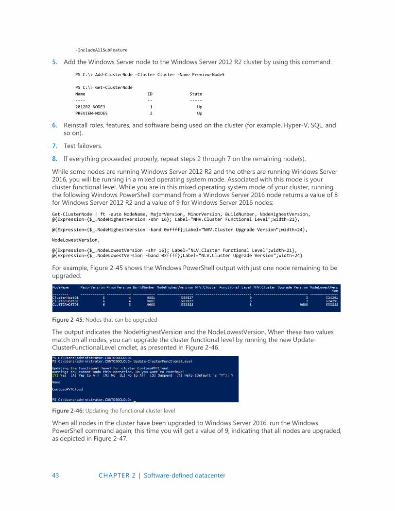
43 CHAPTER 2 | Software-defined datacenter
-IncludeAllSubFeature
5. Add the Windows Server node to the Windows Server 2012 R2 cluster by using this command:
PS C:\> Add-ClusterNode –Cluster Cluster –Name Preview-Node5
PS C:\> Get-ClusterNode
Name ID State
---- -- -----
2012R2-NODE3 1 Up
PREVIEW-NODE5 2 Up
6. Reinstall roles, features, and software being used on the cluster (for example, Hyper-V, SQL, and
so on).
7. Test failovers.
8. If everything proceeded properly, repeat steps 2 through 7 on the remaining node(s).
While some nodes are running Windows Server 2012 R2 and the others are running Windows Server
2016, you will be running in a mixed operating system mode. Associated with this mode is your
cluster functional level. While you are in this mixed operating system mode of your cluster, running
the following Windows PowerShell command from a Windows Server 2016 node returns a value of 8
for Windows Server 2012 R2 and a value of 9 for Windows Server 2016 nodes:
Get-ClusterNode | ft -auto NodeName, MajorVersion, MinorVersion, BuildNumber, NodeHighestVersion, @{Expression={$_.NodeHighestVersion -shr 16}; Label="NHV.Cluster Functional Level";width=21}, @{Expression={$_.NodeHighestVersion -band 0xffff};Label=”NHV.Cluster Upgrade Version”;width=24}, NodeLowestVersion, @{Expression={$_.NodeLowestVersion -shr 16}; Label="NLV.Cluster Functional Level";width=21}, @{Expression={$_.NodeLowestVersion -band 0xffff};Label="NLV.Cluster Upgrade Version";width=24}
For example, Figure 2-45 shows the Windows PowerShell output with just one node remaining to be
upgraded.
Figure 2-45: Nodes that can be upgraded
The output indicates the NodeHighestVersion and the NodeLowestVersion. When these two values
match on all nodes, you can upgrade the cluster functional level by running the new Update-
ClusterFunctionalLevel cmdlet, as presented in Figure 2-46.
Figure 2-46: Updating the functional cluster level
When all nodes in the cluster have been upgraded to Windows Server 2016, run the Windows
PowerShell command again; this time you will get a value of 9, indicating that all nodes are upgraded,
as depicted in Figure 2-47.
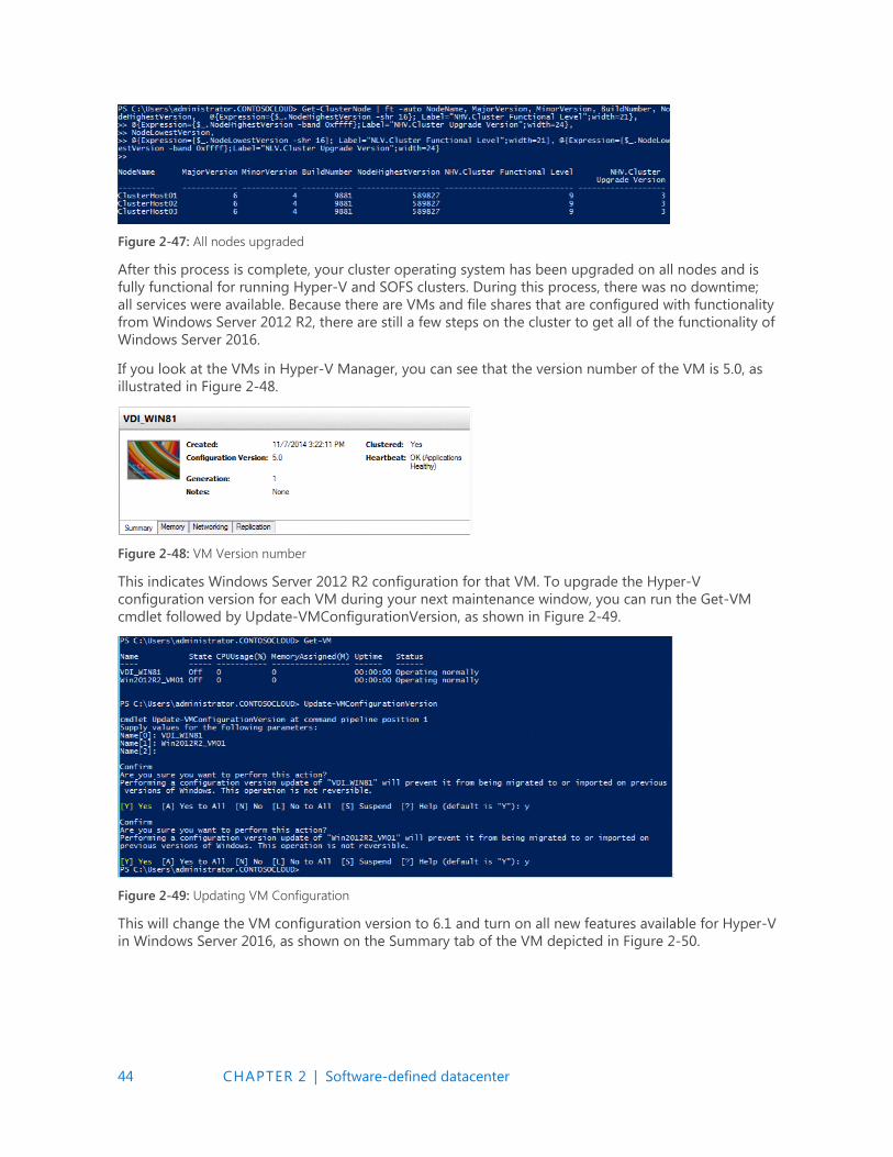
44 CHAPTER 2 | Software-defined datacenter
Figure 2-47: All nodes upgraded
After this process is complete, your cluster operating system has been upgraded on all nodes and is
fully functional for running Hyper-V and SOFS clusters. During this process, there was no downtime;
all services were available. Because there are VMs and file shares that are configured with functionality
from Windows Server 2012 R2, there are still a few steps on the cluster to get all of the functionality of
Windows Server 2016.
If you look at the VMs in Hyper-V Manager, you can see that the version number of the VM is 5.0, as
illustrated in Figure 2-48.
Figure 2-48: VM Version number
This indicates Windows Server 2012 R2 configuration for that VM. To upgrade the Hyper-V
configuration version for each VM during your next maintenance window, you can run the Get-VM
cmdlet followed by Update-VMConfigurationVersion, as shown in Figure 2-49.
Figure 2-49: Updating VM Configuration
This will change the VM configuration version to 6.1 and turn on all new features available for Hyper-V
in Windows Server 2016, as shown on the Summary tab of the VM depicted in Figure 2-50.
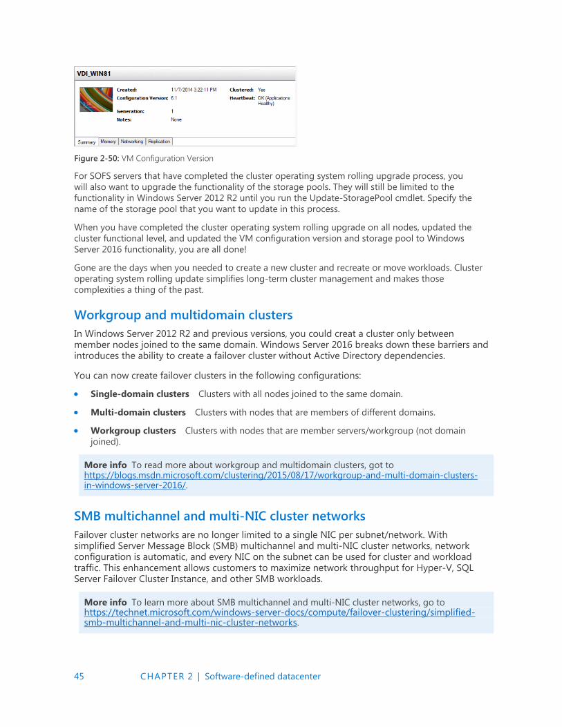
45 CHAPTER 2 | Software-defined datacenter
Figure 2-50: VM Configuration Version
For SOFS servers that have completed the cluster operating system rolling upgrade process, you
will also want to upgrade the functionality of the storage pools. They will still be limited to the
functionality in Windows Server 2012 R2 until you run the Update-StoragePool cmdlet. Specify the
name of the storage pool that you want to update in this process.
When you have completed the cluster operating system rolling upgrade on all nodes, updated the
cluster functional level, and updated the VM configuration version and storage pool to Windows
Server 2016 functionality, you are all done!
Gone are the days when you needed to create a new cluster and recreate or move workloads. Cluster
operating system rolling update simplifies long-term cluster management and makes those
complexities a thing of the past.
Workgroup and multidomain clusters
In Windows Server 2012 R2 and previous versions, you could creat a cluster only between member nodes joined to the same domain. Windows Server 2016 breaks down these barriers and introduces the ability to create a failover cluster without Active Directory dependencies.
You can now create failover clusters in the following configurations:
Single-domain clusters Clusters with all nodes joined to the same domain.
Multi-domain clusters Clusters with nodes that are members of different domains.
Workgroup clusters Clusters with nodes that are member servers/workgroup (not domain
joined).
More info To read more about workgroup and multidomain clusters, got to https://blogs.msdn.microsoft.com/clustering/2015/08/17/workgroup-and-multi-domain-clusters-in-windows-server-2016/.
SMB multichannel and multi-NIC cluster networks
Failover cluster networks are no longer limited to a single NIC per subnet/network. With simplified Server Message Block (SMB) multichannel and multi-NIC cluster networks, network configuration is automatic, and every NIC on the subnet can be used for cluster and workload traffic. This enhancement allows customers to maximize network throughput for Hyper-V, SQL Server Failover Cluster Instance, and other SMB workloads.
More info To learn more about SMB multichannel and multi-NIC cluster networks, go to https://technet.microsoft.com/windows-server-docs/compute/failover-clustering/simplified-smb-multichannel-and-multi-nic-cluster-networks.
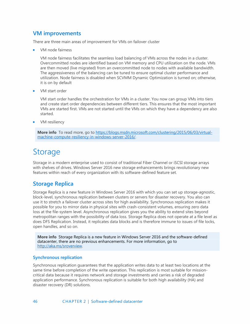
46 CHAPTER 2 | Software-defined datacenter
VM improvements
There are three main areas of improvement for VMs on failover cluster
VM node fairness
VM node fairness facilitates the seamless load balancing of VMs across the nodes in a cluster.
Overcommitted nodes are identified based on VM memory and CPU utilization on the node. VMs
are then moved (live migrated) from an overcommitted node to nodes with available bandwidth.
The aggressiveness of the balancing can be tuned to ensure optimal cluster performance and
utilization. Node fairness is disabled when SCVMM Dynamic Optimization is turned on; otherwise,
it is on by default
VM start order
VM start order handles the orchestration for VMs in a cluster. You now can group VMs into tiers
and create start order dependencies between different tiers. This ensures that the most important
VMs are started first. VMs are not started until the VMs on which they have a dependency are also
started.
VM resiliency
More info To read more, go to https://blogs.msdn.microsoft.com/clustering/2015/06/03/virtual-machine-compute-resiliency-in-windows-server-2016/.
Storage
Storage in a modern enterprise used to consist of traditional Fiber Channel or iSCSI storage arrays
with shelves of drives. Windows Server 2016 new storage enhancements brings revolutionary new
features within reach of every organization with its software-defined feature set.
Storage Replica
Storage Replica is a new feature in Windows Server 2016 with which you can set up storage-agnostic,
block-level, synchronous replication between clusters or servers for disaster recovery. You also can
use it to stretch a failover cluster across sites for high availability. Synchronous replication makes it
possible for you to mirror data in physical sites with crash-consistent volumes, ensuring zero data
loss at the file-system level. Asynchronous replication gives you the ability to extend sites beyond
metropolitan ranges with the possibility of data loss. Storage Replica does not operate at a file level as
does DFS Replication. Instead, it replicates data blocks and is therefore immune to issues of file locks,
open handles, and so on.
More info Storage Replica is a new feature in Windows Server 2016 and the software-defined datacenter, there are no previous enhancements. For more information, go to http://aka.ms/sroverview.
Synchronous replication
Synchronous replication guarantees that the application writes data to at least two locations at the
same time before completion of the write operation. This replication is most suitable for mission-
critical data because it requires network and storage investments and carries a risk of degraded
application performance. Synchronous replication is suitable for both high availability (HA) and
disaster recovery (DR) solutions.
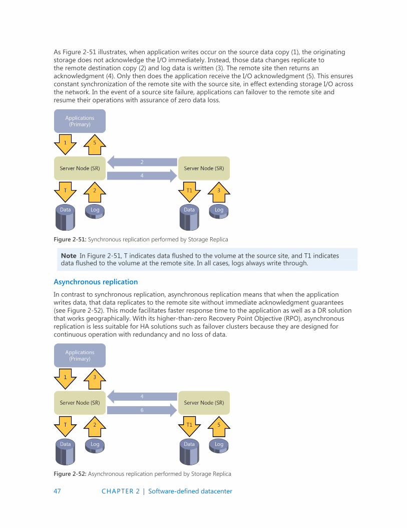
47 CHAPTER 2 | Software-defined datacenter
As Figure 2-51 illustrates, when application writes occur on the source data copy (1), the originating
storage does not acknowledge the I/O immediately. Instead, those data changes replicate to
the remote destination copy (2) and log data is written (3). The remote site then returns an
acknowledgment (4). Only then does the application receive the I/O acknowledgment (5). This ensures
constant synchronization of the remote site with the source site, in effect extending storage I/O across
the network. In the event of a source site failure, applications can failover to the remote site and
resume their operations with assurance of zero data loss.
Figure 2-51: Synchronous replication performed by Storage Replica
Note In Figure 2-51, T indicates data flushed to the volume at the source site, and T1 indicates data flushed to the volume at the remote site. In all cases, logs always write through.
Asynchronous replication
In contrast to synchronous replication, asynchronous replication means that when the application
writes data, that data replicates to the remote site without immediate acknowledgment guarantees
(see Figure 2-52). This mode facilitates faster response time to the application as well as a DR solution
that works geographically. With its higher-than-zero Recovery Point Objective (RPO), asynchronous
replication is less suitable for HA solutions such as failover clusters because they are designed for
continuous operation with redundancy and no loss of data.
Figure 2-52: Asynchronous replication performed by Storage Replica

48 CHAPTER 2 | Software-defined datacenter
As Figure 2-52 illustrates, when the application writes data (1), the replication engine captures and
logs the write (2) and immediately acknowledges to the application (3). The captured data then
replicates to the remote location (4). The remote node processes the copy of the data, writes log data
(5), and lazily acknowledges back to the source copy (6). Because replication performance is no longer
in the application I/O path, the remote site’s responsiveness and distance are less important factors.
There is risk of data loss if the source data is lost while the destination copy of the data is still in buffer
without leaving the source.
Implementation-specific details
Storage Replica utilizes SMB 3.0 as a reliable, high-speed data transport for replication. This grants all
the advantages of SMB 3.0, such as multichannel, RDMA, encryption, signing, and Kerberos-based
security. Storage Replica does not require any changes to Active Directory Domain Services (AD DS) or
any domain administrative permissions. The following table summarizes the implementation-specific
details of Storage Replica:
Feature Details
Type Host-based
Synchronous Yes
Asynchronous Yes (server-to-server only)
Storage hardware agnostic Yes
Replication unit Volume (partition)
Windows Server Stretch Cluster creation Yes
Server-to-server replication Yes
Transport SMB 3.0
Network TCP/IP or RDMA
RDMA iWARP, InfiniBand*
Replication network port firewall requirements Single IANA port (TCP 445 or 5445)
Multipath/Multichannel Yes (SMB 3.0)
Kerberos support Yes (SMB 3.0)
Over the wire encryption and signing Yes (SMB 3.0)
Per volume failovers allowed Yes
Management UI in box Windows PowerShell, Failover Cluster Manager
*Subject to further testing. InfiniBand might require additional long-haul equipment
Note In Windows Server 2016, Storage Replica does not implement transitive replication, the so-called “A-B-C” topology (that is, synchronous replication from server A to server B, and then asynchronous replication from server B to server C). Storage Replica does not implement one-to-many replication. It is possible, for virtualized workloads only, to use Hyper-V Replica as the secondary asynchronous replication mechanism. This means configuring Hyper-V Replica on the source A volume and replicating to a server other than B, forming an “A-to-B + A-to-C” topology.
Requirements
The following are prerequisites for Storage Replica testing:
Windows Server 2016 Datacenter Edition
At least 4 GB of physical memory in each server and at least two cores
AD DS (for SMB to use Kerberos)
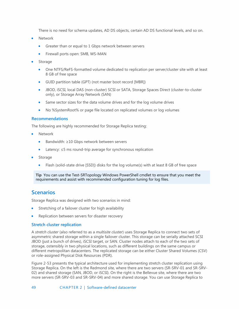
49 CHAPTER 2 | Software-defined datacenter
There is no need for schema updates, AD DS objects, certain AD DS functional levels, and so on.
Network
Greater than or equal to 1 Gbps network between servers
Firewall ports open: SMB, WS-MAN
Storage
One NTFS/ReFS-formatted volume dedicated to replication per server/cluster site with at least
8 GB of free space
GUID partition table (GPT) (not master boot record [MBR])
JBOD, iSCSI, local DAS (non-cluster) SCSI or SATA, Storage Spaces Direct (cluster-to-cluster
only), or Storage Array Network (SAN)
Same sector sizes for the data volume drives and for the log volume drives
No %SystemRoot% or page file located on replicated volumes or log volumes
Recommendations
The following are highly recommended for Storage Replica testing:
Network
Bandwidth: ≥10 Gbps network between servers
Latency: ≤5 ms round-trip average for synchronous replication
Storage
Flash (solid-state drive [SSD]) disks for the log volume(s) with at least 8 GB of free space
Tip You can use the Test-SRTopology Windows PowerShell cmdlet to ensure that you meet the requirements and assist with recommended configuration tuning for log files.
Scenarios
Storage Replica was designed with two scenarios in mind:
Stretching of a failover cluster for high availability
Replication between servers for disaster recovery
Stretch cluster replication
A stretch cluster (also referred to as a multisite cluster) uses Storage Replica to connect two sets of
asymmetric shared storage within a single failover cluster. This storage can be serially attached SCSI
JBOD (just a bunch of drives), iSCSI target, or SAN. Cluster nodes attach to each of the two sets of
storage, ostensibly in two physical locations, such as different buildings on the same campus or
different metropolitan datacenters. The replicated storage can be either Cluster Shared Volumes (CSV)
or role-assigned Physical Disk Resources (PDR).
Figure 2-53 presents the typical architecture used for implementing stretch cluster replication using
Storage Replica. On the left is the Redmond site, where there are two servers (SR-SRV-01 and SR-SRV-
02) and shared storage (SAN, JBOD, or iSCSI). On the right is the Bellevue site, where there are two
more servers (SR-SRV-03 and SR-SRV-04) and more shared storage. You can use Storage Replica to
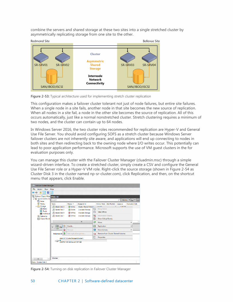
50 CHAPTER 2 | Software-defined datacenter
combine the servers and shared storage at these two sites into a single stretched cluster by
asymmetrically replicating storage from one site to the other.
Figure 2-53: Typical architecture used for implementing stretch cluster replication
This configuration makes a failover cluster tolerant not just of node failures, but entire site failures.
When a single node in a site fails, another node in that site becomes the new source of replication.
When all nodes in a site fail, a node in the other site becomes the source of replication. All of this
occurs automatically, just like a normal nonstretched cluster. Stretch clustering requires a minimum of
two nodes, and the cluster can contain up to 64 nodes.
In Windows Server 2016, the two cluster roles recommended for replication are Hyper-V and General
Use File Server. You should avoid configuring SOFS as a stretch cluster because Windows Server
failover clusters are not inherently site aware, and applications will end up connecting to nodes in
both sites and then redirecting back to the owning node where I/O writes occur. This potentially can
lead to poor application performance. Microsoft supports the use of VM guest clusters in the for
evaluation purposes only.
You can manage this cluster with the Failover Cluster Manager (cluadmin.msc) through a simple
wizard-driven interface. To create a stretched cluster, simply create a CSV and configure the General
Use File Server role or a Hyper-V VM role. Right-click the source storage (shown in Figure 2-54 as
Cluster Disk 3 in the cluster named np-sr-cluster.com), click Replication, and then, on the shortcut
menu that appears, click Enable.
Figure 2-54: Turning on disk replication in Failover Cluster Manager

51 CHAPTER 2 | Software-defined datacenter
In the Configure Storage Replica Wizard that opens, on the Select Destination Data Disk page, select a
destination drive from the available storage displayed for the source drive that you want to replicate.
In Figure 2-55, Cluster Disk 1 is selected as the destination data drive.
Figure 2-55: Selecting a destination disk for the Replica
Follow the remaining wizard prompts to finish configuring your stretched cluster. When configured,
the storage synchronously replicates between the source and destination storage on the cluster.
When completed, replication forms the stretch cluster and Storage Replica protects the data on the
source and destination drives. For example, Figure 2-56 shows the direction of replication after a
subsequent failover. In this case, Cluster Disk 1 is now the source of replication and Cluster Disk 3 is
the destination.
Figure 2-56: Disk information after a replica has been created
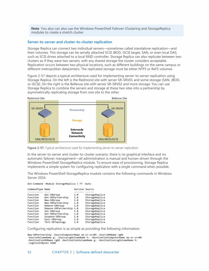
52 CHAPTER 2 | Software-defined datacenter
Note You also can also use the Windows PowerShell Failover-Clustering and StorageReplica modules to create a stretch cluster.
Server-to-server and cluster-to-cluster replication
Storage Replica can connect two individual servers—sometimes called standalone replication—and
their volumes. This storage can be serially attached SCSI JBOD, iSCSI target, SAN, or even local DAS,
such as SCSI drives attached to a local RAID controller. Storage Replica can also replicate between two
clusters as if they were two servers, with any shared storage the cluster considers acceptable.
Replication occurs between two physical locations, such as different buildings on the same campus or
different metropolitan datacenters. The replicated storage must be either NTFS or ReFS volumes.
Figure 2-57 depicts a typical architecture used for implementing server-to-server replication using
Storage Replica. On the left is the Redmond site with server SR-SRV01 and some storage (SAN, JBOD,
or iSCSI). On the right is the Bellevue site with server SR-SRV02 and more storage. You can use
Storage Replica to combine the servers and storage at these two sites into a partnership by
asymmetrically replicating storage from one site to the other.
Figure 2-57: Typical architecture used for implementing server-to-server replication
In the server-to-server and cluster-to-cluster scenario, there is no graphical interface and no
automatic failover management—all administration is manual and human-driven through the
Windows PowerShell StorageReplica module. To ensure ease of provisioning, Storage Replica
implements a simple system for configuring replication with a single command when possible.
The Windows PowerShell StorageReplica module contains the following commands in Windows
Server 2016:
Get-Command -Module StorageReplica | FT –Auto CommandType Name Version Source ----------- ---- ------- ------ Function Get-SRGroup 1.0 StorageReplica Function Get-SRPartnership 1.0 StorageReplica Function New-SRGroup 1.0 StorageReplica Function New-SRPartnership 1.0 StorageReplica Function Remove-SRGroup 1.0 StorageReplica Function Remove-SRPartnership 1.0 StorageReplica Function Set-SRGroup 1.0 StorageReplica Function Set-SRPartnership 1.0 StorageReplica Function Suspend-SRGroup 1.0 StorageReplica Function Sync-SRGroup 1.0 StorageReplica Function Test-SRTopology 1.0 StorageReplica
Configuring replication is as simple as providing the following information:
New-SRPartnership -SourceComputerName np-sr-srv05 -SourceRGName rg01 -SourceVolumeName g: -SourceLogVolumeName h: -DestinationComputerName np-sr-srv06 -DestinationRGName rg02 -DestinationVolumeName g: -DestinationLogVolumeName h: -LogSizeInBytes 16GB

53 CHAPTER 2 | Software-defined datacenter
There are many options for the New-SRPartnership cmdlet, including creating asynchronous
replication. You also can create replication in a more granular fashion by running New-SRGroup on
each server and tying them together by using New-SRPartnership. You can add additional volumes to
a replication group by using Set-SRGroup, and you can run more than one replication group on a
server at a time. Storage Replica will include more cmdlets before the final release, including a cmdlet
to determine how well replication will perform between two servers over a given network, how to
optimally size the replication logs, and what the current write I/O load is on a server you propose for
replication—all without the need to install or configure Storage Replica beforehand.
Storage Replica in Windows Server 2016
The following are some of the key things to know concerning Storage Replica as of the Windows
Server 2016 release:
Network bandwidth and latency with fastest storage There are physical limitations to
synchronous replication. Because Storage Replica implements an I/O filtering mechanism using
logs and requiring network roundtrips, synchronous replication is likely to make application writes
slower. By using low-latency, high-bandwidth networks as well as high-throughput drive
subsystems for the logs, you can minimize performance overhead.
The destination volume is not accessible while replicating When you configure replication,
the destination volume will dismount and no longer be visible in any normal GUI tools or
accessible to any writes by users until you remove replication, or the volume becomes the source
due to failover.
Block-level replication technologies are incompatible with allowing access to the destination’s
mounted file system in a volume; NTFS and ReFS do not support users writing data to the volume
while blocks change underneath them.
Different implementation of asynchronous replication The Microsoft implementation of
asynchronous replication is different than most industry implementations of asynchronous
replication that rely on snapshot-based replication, whereby periodic differential transfers move
to the other node and merge. In contrast, Storage Replica asynchronous replication operates just
like synchronous replication, except that it removes the requirement for a serialized synchronous
acknowledgment from the destination. This means that Storage Replica theoretically has a lower
RPO as it continuously replicates. However, this also means it relies on internal application
consistency guarantees rather than using snapshots to force consistency in application files.
Storage Replica guarantees crash consistency in all replication modes.
Storage Replica is not Distributed File System Replication Volume-level block storage
replication is not a good candidate for use in branch-office scenarios. Branch-office networks tend
to be highly latent, highly utilized, and lower bandwidth, which makes synchronous replication
impractical. A branch office often replicates data in a one-to-many with read-only destinations,
such as for software distribution, and Storage Replica is not capable of this in the first release.
When replicating data from a branch office to a main office, Storage Replica dismounts the
destination volume to prevent direct access.
It is important to note, nevertheless, that many customers use Distributed File System Replication
(DFSR) as a DR solution even though it is often impractical for that scenario—DFSR cannot
replicate open files and is designed to minimize bandwidth usage at the expense of performance,
leading to large recovery-point deltas. Storage Replica might make it possible for you to retire
DFSR from some of these types of DR duties.
Storage Replica is not backup Some IT environments deploy replication systems as backup
solutions due to their zero-data-loss options when compared to daily backups. Storage Replica
replicates all changes to all blocks of data on the volume, regardless of the change type. If a user

54 CHAPTER 2 | Software-defined datacenter
deletes all data from a volume, Storage Replica replicates the deletion instantly to the other
volume, irrevocably removing the data from both servers.
Storage Replica is not Hyper-V Replica or SQL AlwaysOn Storage Replica is a general
purpose, storage-agnostic engine. By definition, it cannot tailor its behavior as ideally as
application-level replication. This might lead to specific feature gaps that encourage you to
deploy or remain on specific application replication technologies.
Storage Spaces Direct Storage Spaces Direct enables service providers and enterprises to use industry standard servers with
internal drives to build highly available and scalable software defined storage. Using servers with
internal drives decreases complexity, increases scalability, and enables use of storage devices that
were not previously possible, such as SATA solid state disks to lower cost of flash storage, or NVMe
solid state disks for better performance.
Storage Spaces Direct removes the need for a shared SAS fabric, simplifying deployment and
configuration. Instead, it uses the network as a storage fabric, using SMB3 and SMB Direct (RDMA) for
high-speed, low-latency CPU-efficient storage. To scale out, simply add more servers to increase
storage capacity and I/O performance. Following are some more features and characteristics of
Storage Spaces Direct:
Storage for Hyper-V and Microsoft Azure Stack The primary use cases for Storage
Spaces Direct is as storage for Hyper-V VMs or as storage for Azure Stack.
Hardware Storage Spaces Direct makes it possible to build highly available and scalable
storage solutions using modern storage hardware like SATA SSD for lower cost and NVMe
SSD for better performance and less CPU overhead. It can also use RDMA-enabled network
infrastructure for low-latency storage with less CPU overhead than traditional Ethernet. Less
CPU overhead means increased workload density.
Prescriptive configurations Microsoft is working closely with its hardware partners to
define and validate prescriptive server configurations for Storage Spaces Direct. Using these
server configurations provides the best possible experience with Storage Spaces Direct with
the full feature set and best performance.
Storage Configurations You can use Storage Spaces Direct with various storage
configurations. The most common configurations are:
SSDs with traditional hard drives, where the SSDs are used as a read/write cache to
accelerate I/O performance.
All-flash configuration with NVMe SSDs and SATA SSDs for extremely high I/O
performance.
Three tiers of physical storage, NVMe SSDs, SATA SSDs, and traditional hard drives.

55 CHAPTER 2 | Software-defined datacenter
Deployment Choice Storage Spaces Direct provides customers with a deployment choice,
either as hyper-converged infrastructure or as converged infrastructure. In a hyper-
converged infrastructure, compute and storage resources are provided by the same
machines, simplifying scale and management. In a converged infrastructure, compute
resources are separate from storage resources, allowing for increased scalability and
independent scaling of compute and storage.
Fault Tolerance Storage Spaces Direct is resilient to drive failures. When drives fail,
degraded data is automatically reconstructed on the remaining drives. Storage Spaces
Direct supports three fault domain types: a) server, b) chassis, and c) rack, and all data
placement, data repair, and data rebalancing will adhere to the fault domain configuration.
Accelerated Erasure Coding Storage Spaces Direct introduces hybrid volumes, which is in
addition to the existing mirror and erasure coding volume types. Hybrid volumes mixes the
best of mirror (performance) with the best of erasure coding (efficiency) into a single volume
with automatic real-time storage tiering.
Efficient VM check-points Storage Spaces Direct utilizes the new ReFSv2 file system,
which when combined with Hyper-V can do very quick and efficient VM checkpoints with
little overhead and storage I/O.
Scalability Storage Spaces Direct can scale from 2 to 16 servers. You can add servers as
needed, and data can be rebalanced to best utilize the additional resources. Microsoft and
Intel demonstrated a 16 server Storage Spaces Direct deployment using all NVMe SSDs at
IDF 2015.
Health Service Storage Spaces Direct includes an intelligent built-in diagnostic engine
that makes it possible for administrators with limited technical expertise to monitor and
operate the system day to day.
The Health Service actively monitors the underlying cluster, storage hardware, and
software-defined storage stack to detect problems and generate alerts that contain
precise instructions for how to react.
Performance and capacity information is aggregated to present a holistic, high-level
view of available resources.
Frequent tasks such as drive replacement and drive firmware updates are automated to
reduce the burden on the administrator.
To help understand Storage Spaces Direct, let’s begin by examining Storage Spaces in Windows
Server 2012 R2 HA storage systems. In Windows Server 2012 R2, an HA system using Storage Spaces
requires drive devices to be physically connected to all storage nodes. For the drive devices to be
physically connected to all storage nodes, they need to reside in an external JBOD chassis, with each
storage node having physical connectivity to the external JBOD. Also, because multiple storage nodes
will be connecting to each drive, the drive devices need to be serial-attached SCSI (SAS) because the
SAS protocol allows for this sharing where drives such as SATA do not allow multi-initiator. Because of
these requirements, this deployment is referred to as Storage Spaces Shared JBOD to contrast it with
Storage Spaces Direct. Figure 2-58 shows a Storage Spaces Shared JBOD deployment.
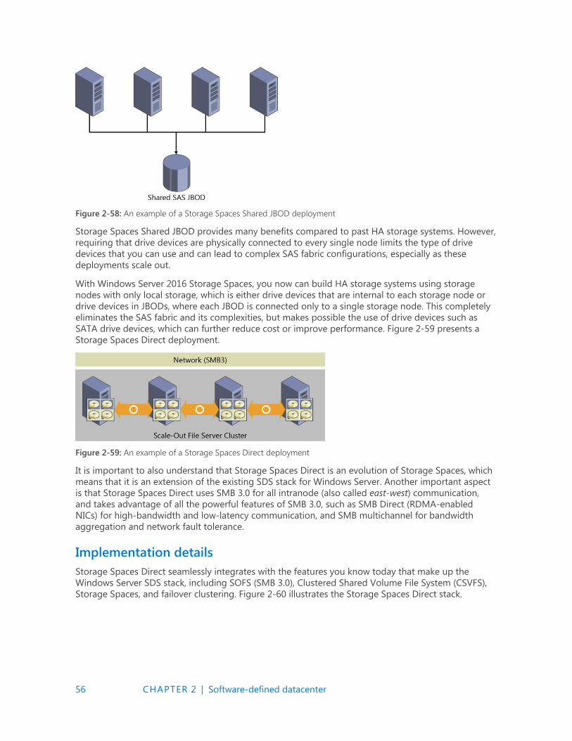
56 CHAPTER 2 | Software-defined datacenter
Figure 2-58: An example of a Storage Spaces Shared JBOD deployment
Storage Spaces Shared JBOD provides many benefits compared to past HA storage systems. However,
requiring that drive devices are physically connected to every single node limits the type of drive
devices that you can use and can lead to complex SAS fabric configurations, especially as these
deployments scale out.
With Windows Server 2016 Storage Spaces, you now can build HA storage systems using storage
nodes with only local storage, which is either drive devices that are internal to each storage node or
drive devices in JBODs, where each JBOD is connected only to a single storage node. This completely
eliminates the SAS fabric and its complexities, but makes possible the use of drive devices such as
SATA drive devices, which can further reduce cost or improve performance. Figure 2-59 presents a
Storage Spaces Direct deployment.
Figure 2-59: An example of a Storage Spaces Direct deployment
It is important to also understand that Storage Spaces Direct is an evolution of Storage Spaces, which
means that it is an extension of the existing SDS stack for Windows Server. Another important aspect
is that Storage Spaces Direct uses SMB 3.0 for all intranode (also called east-west) communication,
and takes advantage of all the powerful features of SMB 3.0, such as SMB Direct (RDMA-enabled
NICs) for high-bandwidth and low-latency communication, and SMB multichannel for bandwidth
aggregation and network fault tolerance.
Implementation details
Storage Spaces Direct seamlessly integrates with the features you know today that make up the
Windows Server SDS stack, including SOFS (SMB 3.0), Clustered Shared Volume File System (CSVFS),
Storage Spaces, and failover clustering. Figure 2-60 illustrates the Storage Spaces Direct stack.

57 CHAPTER 2 | Software-defined datacenter
Figure 2-60: The Storage Spaces Direct stack
The updated stack includes the following, starting from the bottom:
Hardware The storage system consists of a minimum of four storage nodes with local storage.
Each storage node can have internal drives or drives in an external SAS-connected JBOD
enclosure. The drive devices can be SATA disks or SAS disks.
Software Storage Bus The Software Storage Bus spans all of the storage nodes and brings
together the local storage in each node, so all drives are visible to the Storage Spaces layer above.
Storage Spaces Storage Spaces provides storage pools and virtual drives. The storage pool can
span all of the local storage across the nodes. The virtual drives provide resiliency to drive or node
failures because data copies are stored on different storage nodes.
Resilient File System (ReFS) ReFS provides the file system in which the Hyper-V VM files are
stored. ReFS is a premier file system in Windows Server 2016 for virtualized deployments and
includes optimizations for Storage Spaces such as error detection and automatic correction. In
addition, ReFS provides accelerations for VHD(X) operations such as fixed VHD(X) creation,
dynamic VHD(X) growth, and VHD(X) merge. CSVFS layers above ReFS bring all the mounted
volumes into a single namespace.
SOFS This is the top layer of the storage stack that provides remote access to the storage
system by using the SMB 3.0 access protocol.
Improved scalability
You can deploy Storage Spaces Direct using storage nodes with either local storage or nonshared
JBODs. In previous versions of Windows Server, scaling out Storage Spaces solutions required a
concurrent increase in the scale of the SAS fabric that joined the storage nodes to the shared SAS
JBODs. In contrast, with Storage Spaces Direct, you can set up a model that removes the complexities
of the SAS fabric, making scale-out as simple as adding a new storage node, either with internal
storage or attached to a nonshared JBOD. Scaling out by adding storage nodes provides more
flexibility in storage planning because storage expansion is no longer bound by the number of drive
slots in a shared SAS JBOD.
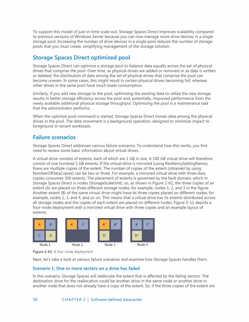
58 CHAPTER 2 | Software-defined datacenter
To support this model of just-in-time scale-out, Storage Spaces Direct improves scalability compared
to previous versions of Windows Server because you can now manage more drive devices in a single
storage pool. Increasing the number of drive devices in a single pool reduces the number of storage
pools that you must create, simplifying management of the storage solution.
Storage Spaces Direct optimized pool
Storage Spaces Direct can optimize a storage pool to balance data equally across the set of physical
drives that comprise the pool. Over time, as physical drives are added or removed or as data is written
or deleted, the distribution of data among the set of physical drives that comprise the pool can
become uneven. In some cases, this might result in certain physical drives becoming full, whereas
other drives in the same pool have much lower consumption.
Similarly, if you add new storage to the pool, optimizing the existing data to utilize the new storage
results in better storage efficiency across the pool and, potentially, improved performance from the
newly available additional physical storage throughput. Optimizing the pool is a maintenance task
that the administrator performs.
When the optimize pool command is started, Storage Spaces Direct moves data among the physical
drives in the pool. The data movement is a background operation, designed to minimize impact to
foreground or tenant workloads.
Failure scenarios
Storage Spaces Direct addresses various failure scenarios. To understand how this works, you first
need to review some basic information about virtual drives.
A virtual drive consists of extents, each of which are 1 GB in size. A 100 GB virtual drive will therefore
consist of one hundred 1 GB extents. If the virtual drive is mirrored (using ResiliencySettingName),
there are multiple copies of the extent. The number of copies of the extent (obtained by using
NumberOfDataCopies) can be two or three. For example, a mirrored virtual drive with three data
copies consumes 300 extents. The placement of extents is governed by the fault domain, which in
Storage Spaces Direct is nodes (StorageScaleUnit), so, as shown in Figure 2-61, the three copies of an
extent (A) are placed on three different storage nodes; for example, nodes 1, 2, and 3 in the figure.
Another extent (B) of the same virtual drive might have its three copies placed on different nodes; for
example, nodes 1, 3, and 4, and so on. This means that a virtual drive has its extents distributed across
all storage nodes and the copies of each extent are placed on different nodes. Figure 3-11 depicts a
four-node deployment with a mirrored virtual drive with three copies and an example layout of
extents.
Figure 2-61: A four-node deployment
Next, let’s take a look at various failure scenarios and examine how Storage Spaces handles them.
Scenario 1: One or more sectors on a drive has failed
In this scenario, Storage Spaces will reallocate the extent that is affected by the failing sectors. The
destination drive for the reallocation could be another drive in the same node or another drive in
another node that does not already have a copy of the extent. So, if the three copies of the extent are
59 CHAPTER 2 | Software-defined datacenter
on node A, B, and C, and the extent on node A is affected by a sector failure, the new copy can be
generated on a different drive in node A or any drive in Node D. Drives in node B and C cannot be
used, because these two nodes already have a copy of the extent.
Scenario 2: A drive has failed
In this scenario, Storage Spaces retires the physical drive from the storage pool when it discovers the
drive has failed. After the physical drive has been retired, each virtual drive starts its repair process.
Because the physical drive has been retired, the virtual drives generate a new copy of the extents that
were on the retired physical drive. The new copies follow the same logic as in scenario 1.
Scenario 3: A drive is missing
In this scenario, Storage Spaces will do one of two things:
If only the physical drive is missing, Storage Spaces will retire the disk.
If the storage node or the physical enclosure to which the physical drive is attached is also
missing, Storage Spaces will not retire the physical drive.
The reason Storage Spaces won’t retire the physical drive in this second case is that during a storage
node restart or temporary maintenance of a storage node, all the drives and physical enclosures
associated with that node will be reported missing. Automatically retiring all of those drives and
enclosures would potentially result in a massive amount of repair activity because you would need to
rebuild all of the extents on those drives elsewhere in the storage system. This could easily be multiple
terabytes of data. If the drives and enclosures are really missing and will not come back to the storage
system, the administrator will need to retire the missing physical drives and start the repair process.
Scenario 4: Storage node restart or maintenance
In this scenario, Storage Spaces does not automatically retire physical drives from the storage pool for
the reasons described earlier in scenario 3. When the storage node comes back online, Storage
Spaces automatically updates all extents that are not up to date with the copies that were unaffected
by the restart or maintenance.
Scenario 5: Permanent storage node failure
In this scenario, Storage Spaces requires the administrator to retire all of the affected physical drives
from the storage pool, add additional storage nodes to the storage system if needed, and then begin
repair. This is not an automatic process, because Storage Spaces does not know if the failure is
temporary or permanent. It is not desired to initiate a repair that could potentially result in significant
repair activity.
More info To learn more about Storage Spaces Direct in Windows Server 2016, go to https://technet.microsoft.com/library/mt126109.aspx.
Deduplication
In Windows Server 2016 Deduplication, the core focus is to have significant impact on the scale and
performance that you can address with this technology. With this shift in focus, you can now use
Windows Server 2016 in the following scenarios:
Volumes up to 64 TB
File sizes up to 1 TB
Virtualized backup
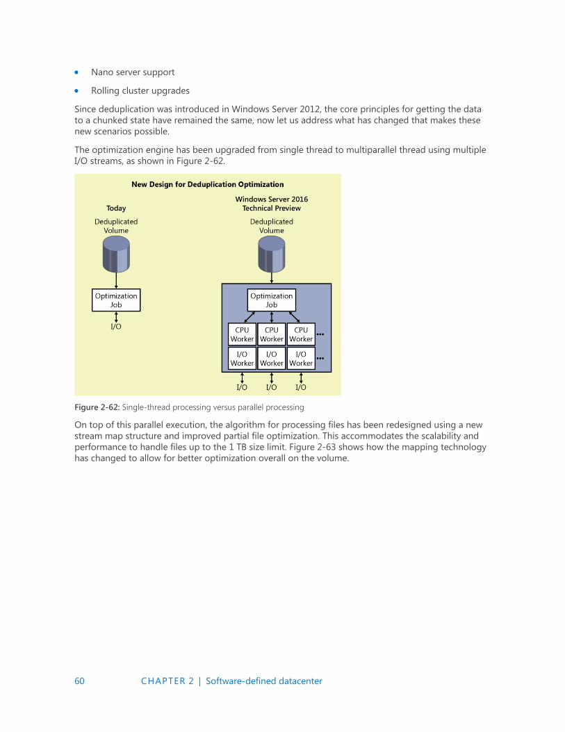
60 CHAPTER 2 | Software-defined datacenter
Nano server support
Rolling cluster upgrades
Since deduplication was introduced in Windows Server 2012, the core principles for getting the data
to a chunked state have remained the same, now let us address what has changed that makes these
new scenarios possible.
The optimization engine has been upgraded from single thread to multiparallel thread using multiple
I/O streams, as shown in Figure 2-62.
Figure 2-62: Single-thread processing versus parallel processing
On top of this parallel execution, the algorithm for processing files has been redesigned using a new
stream map structure and improved partial file optimization. This accommodates the scalability and
performance to handle files up to the 1 TB size limit. Figure 2-63 shows how the mapping technology
has changed to allow for better optimization overall on the volume.
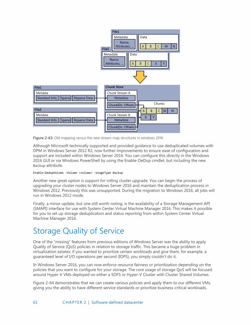
61 CHAPTER 2 | Software-defined datacenter
Figure 2-63: Old mapping versus the new stream map structures in windows 2016
Although Microsoft technically supported and provided guidance to use deduplicated volumes with
DPM in Windows Server 2012 R2, now further improvements to ensure ease of configuration and
support are included within Windows Server 2016. You can configure this directly in the Windows
2016 GUI or via Windows PowerShell by using the Enable-DeDup cmdlet, but including the new
Backup attribute.
Enable-DedupVolume -Volume <volume> -UsageType Backup
Another new great option is support for rolling cluster upgrade. You can begin the process of
upgrading your cluster nodes to Windows Server 2016 and maintain the deduplication process in
Windows 2012. Previously this was unsupported. During the migration to Windows 2016, all jobs will
run in Windows 2012 mode.
Finally, a minor update, but one still worth noting, is the availability of a Storage Management API
(SMAPI) interface for use with System Center Virtual Machine Manager 2016. This makes it possible
for you to set up storage deduplication and status reporting from within System Center Virtual
Machine Manager 2016.
Storage Quality of Service
One of the “missing” features from previous editions of Windows Server was the ability to apply
Quality of Service (QoS) policies in relation to storage traffic. This became a huge problem in
virtualization estates; if you wanted to prioritize certain workloads and give them, for example, a
guaranteed level of I/O operations per second (IOPS), you simply couldn’t do it.
In Windows Server 2016, you can now enforce resource fairness or prioritization depending on the
policies that you want to configure for your storage. The core usage of storage QoS will be focused
around Hyper-V VMs deployed on either a SOFS or Hyper-V Cluster with Cluster Shared Volumes.
Figure 2-64 demonstrates that we can create various policies and apply them to our different VMs,
giving you the ability to have different service standards or prioritize business-critical workloads.
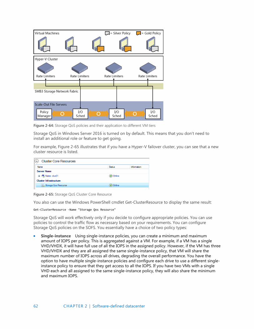
62 CHAPTER 2 | Software-defined datacenter
Figure 2-64: Storage QoS policies and their application to different VM tiers
Storage QoS in Windows Server 2016 is turned on by default. This means that you don’t need to
install an additional role or feature to get going.
For example, Figure 2-65 illustrates that if you have a Hyper-V failover cluster, you can see that a new
cluster resource is listed.
Figure 2-65: Storage QoS Cluster Core Resource
You also can use the Windows PowerShell cmdlet Get-ClusterResource to display the same result:
Get-ClusterResource -Name "Storage Qos Resource"
Storage QoS will work effectively only if you decide to configure appropriate policies. You can use
policies to control the traffic flow as necessary based on your requirements. You can configure
Storage QoS policies on the SOFS. You essentially have a choice of two policy types:
Single-instance Using single-instance policies, you can create a minimum and maximum
amount of IOPS per policy. This is aggregated against a VM. For example, if a VM has a single
VHD/VHDX, it will have full use of all the IOPS in the assigned policy. However, if the VM has three
VHD/VHDX and they are all assigned the same single-instance policy, that VM will share the
maximum number of IOPS across all drives, degrading the overall performance. You have the
option to have multiple single-instance policies and configure each drive to use a different single-
instance policy to ensure that they get access to all the IOPS. If you have two VMs with a single
VHD each and all assigned to the same single-instance policy, they will also share the minimum
and maximum IOPS.
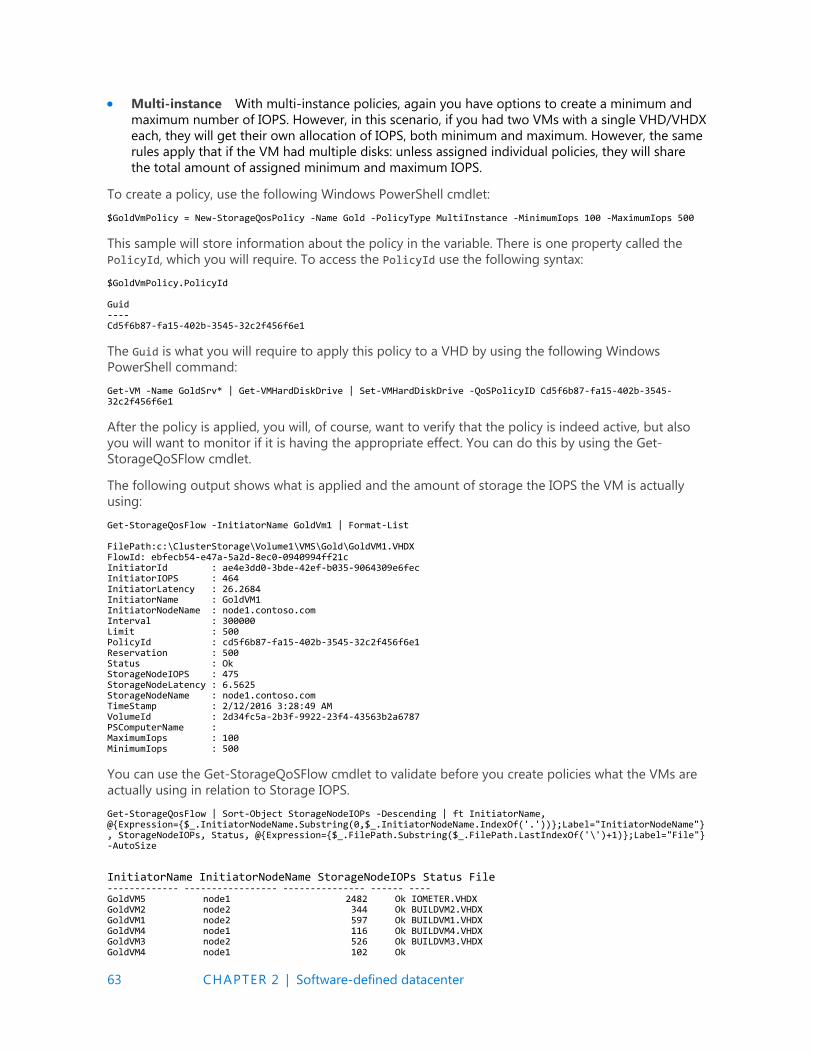
63 CHAPTER 2 | Software-defined datacenter
Multi-instance With multi-instance policies, again you have options to create a minimum and
maximum number of IOPS. However, in this scenario, if you had two VMs with a single VHD/VHDX
each, they will get their own allocation of IOPS, both minimum and maximum. However, the same
rules apply that if the VM had multiple disks: unless assigned individual policies, they will share
the total amount of assigned minimum and maximum IOPS.
To create a policy, use the following Windows PowerShell cmdlet:
$GoldVmPolicy = New-StorageQosPolicy -Name Gold -PolicyType MultiInstance -MinimumIops 100 -MaximumIops 500
This sample will store information about the policy in the variable. There is one property called the
PolicyId, which you will require. To access the PolicyId use the following syntax:
$GoldVmPolicy.PolicyId Guid ---- Cd5f6b87-fa15-402b-3545-32c2f456f6e1
The Guid is what you will require to apply this policy to a VHD by using the following Windows
PowerShell command:
Get-VM -Name GoldSrv* | Get-VMHardDiskDrive | Set-VMHardDiskDrive -QoSPolicyID Cd5f6b87-fa15-402b-3545-32c2f456f6e1
After the policy is applied, you will, of course, want to verify that the policy is indeed active, but also
you will want to monitor if it is having the appropriate effect. You can do this by using the Get-
StorageQoSFlow cmdlet.
The following output shows what is applied and the amount of storage the IOPS the VM is actually
using:
Get-StorageQosFlow -InitiatorName GoldVm1 | Format-List FilePath:c:\ClusterStorage\Volume1\VMS\Gold\GoldVM1.VHDX FlowId: ebfecb54-e47a-5a2d-8ec0-0940994ff21c InitiatorId : ae4e3dd0-3bde-42ef-b035-9064309e6fec InitiatorIOPS : 464 InitiatorLatency : 26.2684 InitiatorName : GoldVM1 InitiatorNodeName : node1.contoso.com Interval : 300000 Limit : 500 PolicyId : cd5f6b87-fa15-402b-3545-32c2f456f6e1 Reservation : 500 Status : Ok StorageNodeIOPS : 475 StorageNodeLatency : 6.5625 StorageNodeName : node1.contoso.com TimeStamp : 2/12/2016 3:28:49 AM VolumeId : 2d34fc5a-2b3f-9922-23f4-43563b2a6787 PSComputerName : MaximumIops : 100 MinimumIops : 500
You can use the Get-StorageQoSFlow cmdlet to validate before you create policies what the VMs are
actually using in relation to Storage IOPS.
Get-StorageQosFlow | Sort-Object StorageNodeIOPs -Descending | ft InitiatorName, @{Expression={$_.InitiatorNodeName.Substring(0,$_.InitiatorNodeName.IndexOf('.'))};Label="InitiatorNodeName"}, StorageNodeIOPs, Status, @{Expression={$_.FilePath.Substring($_.FilePath.LastIndexOf('\')+1)};Label="File"} -AutoSize InitiatorName InitiatorNodeName StorageNodeIOPs Status File ------------- ----------------- --------------- ------ ---- GoldVM5 node1 2482 Ok IOMETER.VHDX GoldVM2 node2 344 Ok BUILDVM2.VHDX GoldVM1 node2 597 Ok BUILDVM1.VHDX GoldVM4 node1 116 Ok BUILDVM4.VHDX GoldVM3 node2 526 Ok BUILDVM3.VHDX GoldVM4 node1 102 Ok
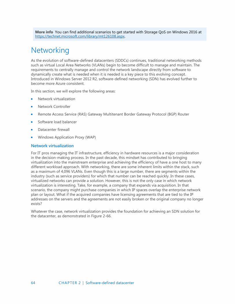
64 CHAPTER 2 | Software-defined datacenter
More info You can find additional scenarios to get started with Storage QoS on Windows 2016 at https://technet.microsoft.com/library/mt126108.aspx.
Networking
As the evolution of software-defined datacenters (SDDCs) continues, traditional networking methods
such as virtual Local Area Networks (VLANs) begin to become difficult to manage and maintain. The
requirements to centrally manage and control the network landscape directly from software to
dynamically create what is needed when it is needed is a key piece to this evolving concept.
Introduced in Windows Server 2012 R2, software-defined networking (SDN) has evolved further to
become more Azure consistent.
In this section, we will explore the following areas:
Network virtualization
Network Controller
Remote Access Service (RAS) Gateway Multitenant Border Gateway Protocol (BGP) Router
Software load balancer
Datacenter firewall
Windows Application Proxy (WAP)
Network virtualization
For IT pros managing the IT infrastructure, efficiency in hardware resources is a major consideration
in the decision-making process. In the past decade, this mindset has contributed to bringing
virtualization into the mainstream enterprise and achieving the efficiency of have a one host to many
different workload approach. With networking, there are some inherent limits within the stack, such
as a maximum of 4,096 VLANs. Even though this is a large number, there are segments within the
industry (such as service providers) for which that number can be reached quickly. In these cases,
virtualized networks can provide a solution. However, this is not the only case in which network
virtualization is interesting. Take, for example, a company that expands via acquisition. In that
scenario, the company might purchase companies in which IP spaces overlap the enterprise network
plan or layout. What if the acquired companies have licensing agreements that are tied to the IP
addresses on the servers and the agreements are not easily broken or the original company no longer
exists?
Whatever the case, network virtualization provides the foundation for achieving an SDN solution for
the datacenter, as demonstrated in Figure 2-66.
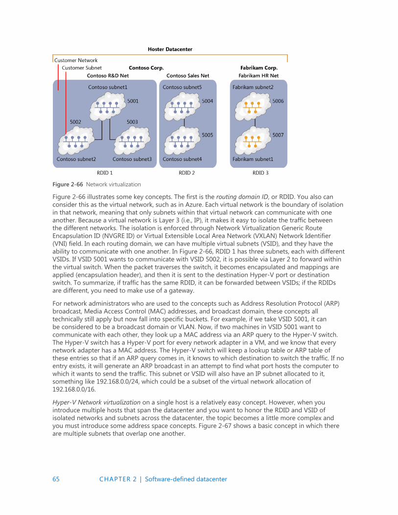
65 CHAPTER 2 | Software-defined datacenter
Figure 2-66 Network virtualization
Figure 2-66 illustrates some key concepts. The first is the routing domain ID, or RDID. You also can
consider this as the virtual network, such as in Azure. Each virtual network is the boundary of isolation
in that network, meaning that only subnets within that virtual network can communicate with one
another. Because a virtual network is Layer 3 (i.e., IP), it makes it easy to isolate the traffic between
the different networks. The isolation is enforced through Network Virtualization Generic Route
Encapsulation ID (NVGRE ID) or Virtual Extensible Local Area Network (VXLAN) Network Identifier
(VNI) field. In each routing domain, we can have multiple virtual subnets (VSID), and they have the
ability to communicate with one another. In Figure 2-66, RDID 1 has three subnets, each with different
VSIDs. If VSID 5001 wants to communicate with VSID 5002, it is possible via Layer 2 to forward within
the virtual switch. When the packet traverses the switch, it becomes encapsulated and mappings are
applied (encapsulation header), and then it is sent to the destination Hyper-V port or destination
switch. To summarize, if traffic has the same RDID, it can be forwarded between VSIDs; if the RDIDs
are different, you need to make use of a gateway.
For network administrators who are used to the concepts such as Address Resolution Protocol (ARP)
broadcast, Media Access Control (MAC) addresses, and broadcast domain, these concepts all
technically still apply but now fall into specific buckets. For example, if we take VSID 5001, it can
be considered to be a broadcast domain or VLAN. Now, if two machines in VSID 5001 want to
communicate with each other, they look up a MAC address via an ARP query to the Hyper-V switch.
The Hyper-V switch has a Hyper-V port for every network adapter in a VM, and we know that every
network adapter has a MAC address. The Hyper-V switch will keep a lookup table or ARP table of
these entries so that if an ARP query comes in, it knows to which destination to switch the traffic. If no
entry exists, it will generate an ARP broadcast in an attempt to find what port hosts the computer to
which it wants to send the traffic. This subnet or VSID will also have an IP subnet allocated to it,
something like 192.168.0.0/24, which could be a subset of the virtual network allocation of
192.168.0.0/16.
Hyper-V Network virtualization on a single host is a relatively easy concept. However, when you
introduce multiple hosts that span the datacenter and you want to honor the RDID and VSID of
isolated networks and subnets across the datacenter, the topic becomes a little more complex and
you must introduce some address space concepts. Figure 2-67 shows a basic concept in which there
are multiple subnets that overlap one another.
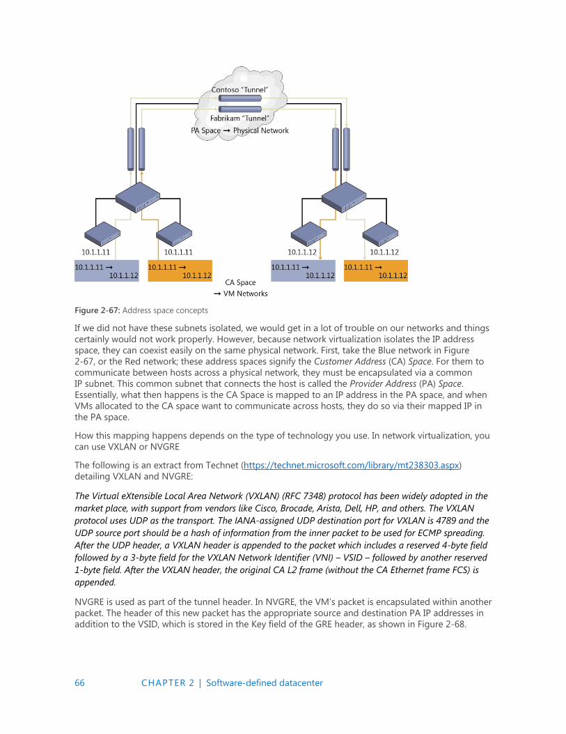
66 CHAPTER 2 | Software-defined datacenter
Figure 2-67: Address space concepts
If we did not have these subnets isolated, we would get in a lot of trouble on our networks and things
certainly would not work properly. However, because network virtualization isolates the IP address
space, they can coexist easily on the same physical network. First, take the Blue network in Figure
2-67, or the Red network; these address spaces signify the Customer Address (CA) Space. For them to
communicate between hosts across a physical network, they must be encapsulated via a common
IP subnet. This common subnet that connects the host is called the Provider Address (PA) Space.
Essentially, what then happens is the CA Space is mapped to an IP address in the PA space, and when
VMs allocated to the CA space want to communicate across hosts, they do so via their mapped IP in
the PA space.
How this mapping happens depends on the type of technology you use. In network virtualization, you
can use VXLAN or NVGRE
The following is an extract from Technet (https://technet.microsoft.com/library/mt238303.aspx)
detailing VXLAN and NVGRE:
The Virtual eXtensible Local Area Network (VXLAN) (RFC 7348) protocol has been widely adopted in the
market place, with support from vendors like Cisco, Brocade, Arista, Dell, HP, and others. The VXLAN
protocol uses UDP as the transport. The IANA-assigned UDP destination port for VXLAN is 4789 and the
UDP source port should be a hash of information from the inner packet to be used for ECMP spreading.
After the UDP header, a VXLAN header is appended to the packet which includes a reserved 4-byte field
followed by a 3-byte field for the VXLAN Network Identifier (VNI) – VSID – followed by another reserved
1-byte field. After the VXLAN header, the original CA L2 frame (without the CA Ethernet frame FCS) is
appended.
NVGRE is used as part of the tunnel header. In NVGRE, the VM’s packet is encapsulated within another
packet. The header of this new packet has the appropriate source and destination PA IP addresses in
addition to the VSID, which is stored in the Key field of the GRE header, as shown in Figure 2-68.
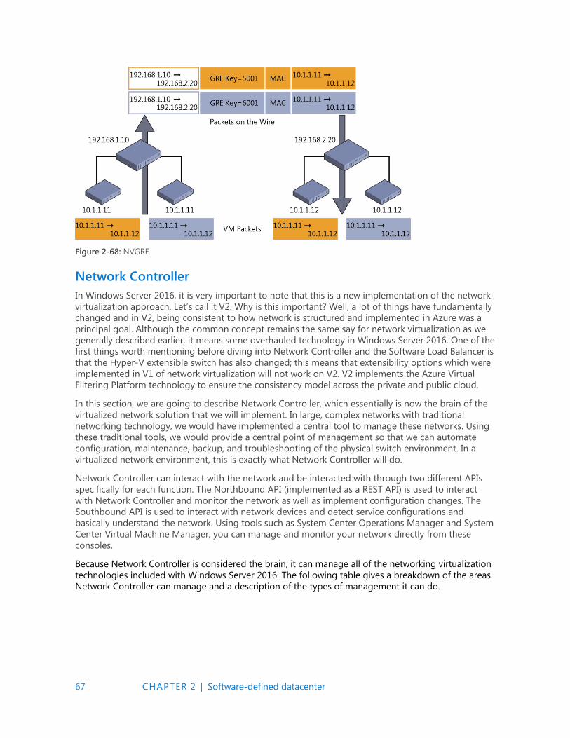
67 CHAPTER 2 | Software-defined datacenter
Figure 2-68: NVGRE
Network Controller
In Windows Server 2016, it is very important to note that this is a new implementation of the network
virtualization approach. Let’s call it V2. Why is this important? Well, a lot of things have fundamentally
changed and in V2, being consistent to how network is structured and implemented in Azure was a
principal goal. Although the common concept remains the same say for network virtualization as we
generally described earlier, it means some overhauled technology in Windows Server 2016. One of the
first things worth mentioning before diving into Network Controller and the Software Load Balancer is
that the Hyper-V extensible switch has also changed; this means that extensibility options which were
implemented in V1 of network virtualization will not work on V2. V2 implements the Azure Virtual
Filtering Platform technology to ensure the consistency model across the private and public cloud.
In this section, we are going to describe Network Controller, which essentially is now the brain of the
virtualized network solution that we will implement. In large, complex networks with traditional
networking technology, we would have implemented a central tool to manage these networks. Using
these traditional tools, we would provide a central point of management so that we can automate
configuration, maintenance, backup, and troubleshooting of the physical switch environment. In a
virtualized network environment, this is exactly what Network Controller will do.
Network Controller can interact with the network and be interacted with through two different APIs
specifically for each function. The Northbound API (implemented as a REST API) is used to interact
with Network Controller and monitor the network as well as implement configuration changes. The
Southbound API is used to interact with network devices and detect service configurations and
basically understand the network. Using tools such as System Center Operations Manager and System
Center Virtual Machine Manager, you can manage and monitor your network directly from these
consoles.
Because Network Controller is considered the brain, it can manage all of the networking virtualization
technologies included with Windows Server 2016. The following table gives a breakdown of the areas
Network Controller can manage and a description of the types of management it can do.
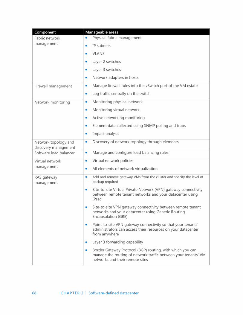
68 CHAPTER 2 | Software-defined datacenter
Component Manageable areas
Fabric network
management
Physical fabric management
IP subnets
VLANS
Layer 2 switches
Layer 3 switches
Network adapters in hosts
Firewall management Manage firewall rules into the vSwitch port of the VM estate
Log traffic centrally on the switch
Network monitoring Monitoring physical network
Monitoring virtual network
Active networking monitoring
Element data collected using SNMP polling and traps
Impact analysis
Network topology and
discovery management
Discovery of network topology through elements
Software load balancer Manage and configure load balancing rules
Virtual network
management
Virtual network policies
All elements of network virtualization
RAS gateway
management
Add and remove gateway VMs from the cluster and specify the level of
backup required
Site-to-site Virtual Private Network (VPN) gateway connectivity
between remote tenant networks and your datacenter using
IPsec
Site-to-site VPN gateway connectivity between remote tenant
networks and your datacenter using Generic Routing
Encapsulation (GRE)
Point-to-site VPN gateway connectivity so that your tenants’
administrators can access their resources on your datacenter
from anywhere
Layer 3 forwarding capability
Border Gateway Protocol (BGP) routing, with which you can
manage the routing of network traffic between your tenants’ VM
networks and their remote sites
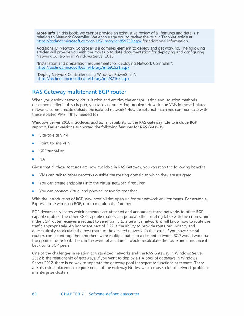
69 CHAPTER 2 | Software-defined datacenter
More info In this book, we cannot provide an exhaustive review of all features and details in relation to Network Controller. We encourage you to review the public TechNet article at https://technet.microsoft.com/en-US/library/dn859239.aspx for additional information.
Additionally, Network Controller is a complex element to deploy and get working. The following articles will provide you with the most up to date documentation for deploying and configuring Network Controller in Windows Server 2016:
“Installation and preparation requirements for deploying Network Controller”: https://technet.microsoft.com/library/mt691521.aspx
“Deploy Network Controller using Windows PowerShell”: https://technet.microsoft.com/library/mt282165.aspx
RAS Gateway multitenant BGP router
When you deploy network virtualization and employ the encapsulation and isolation methods
described earlier in this chapter, you face an interesting problem: How do the VMs in these isolated
networks communicate outside the isolated network? How do external machines communicate with
these isolated VMs if they needed to?
Windows Server 2016 introduces additional capability to the RAS Gateway role to include BGP
support. Earlier versions supported the following features for RAS Gateway:
Site-to-site VPN
Point-to-site VPN
GRE tunneling
NAT
Given that all these features are now available in RAS Gateway, you can reap the following benefits:
VMs can talk to other networks outside the routing domain to which they are assigned.
You can create endpoints into the virtual network if required.
You can connect virtual and physical networks together.
With the introduction of BGP, new possibilities open up for our network environments. For example,
Express route works on BGP, not to mention the Internet!
BGP dynamically learns which networks are attached and announces these networks to other BGP-
capable routers. The other BGP-capable routers can populate their routing table with the entries, and
if the BGP router receives a request to send traffic to a tenant’s network, it will know how to route the
traffic appropriately. An important part of BGP is the ability to provide route redundancy and
automatically recalculate the best route to the desired network. In that case, if you have several
routers connected together and there were multiple paths to a desired network, BGP would work out
the optimal route to it. Then, in the event of a failure, it would recalculate the route and announce it
back to its BGP peers.
One of the challenges in relation to virtualized networks and the RAS Gateway in Windows Server
2012 is the relationship of gateways. If you want to deploy a HA pool of gateways in Windows
Server 2012, there is no way to separate the gateway pool for separate functions or tenants. There
are also strict placement requirements of the Gateway Nodes, which cause a lot of network problems
in enterprise clusters.
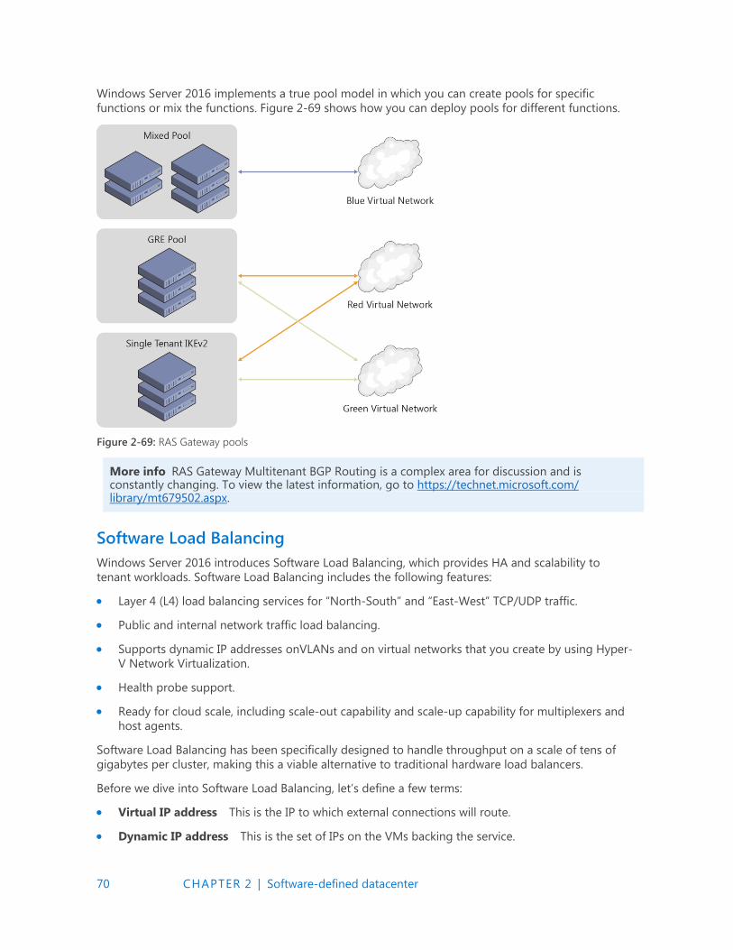
70 CHAPTER 2 | Software-defined datacenter
Windows Server 2016 implements a true pool model in which you can create pools for specific
functions or mix the functions. Figure 2-69 shows how you can deploy pools for different functions.
Figure 2-69: RAS Gateway pools
More info RAS Gateway Multitenant BGP Routing is a complex area for discussion and is constantly changing. To view the latest information, go to https://technet.microsoft.com/ library/mt679502.aspx.
Software Load Balancing
Windows Server 2016 introduces Software Load Balancing, which provides HA and scalability to
tenant workloads. Software Load Balancing includes the following features:
Layer 4 (L4) load balancing services for “North-South” and “East-West” TCP/UDP traffic.
Public and internal network traffic load balancing.
Supports dynamic IP addresses onVLANs and on virtual networks that you create by using Hyper-
V Network Virtualization.
Health probe support.
Ready for cloud scale, including scale-out capability and scale-up capability for multiplexers and
host agents.
Software Load Balancing has been specifically designed to handle throughput on a scale of tens of
gigabytes per cluster, making this a viable alternative to traditional hardware load balancers.
Before we dive into Software Load Balancing, let’s define a few terms:
Virtual IP address This is the IP to which external connections will route.
Dynamic IP address This is the set of IPs on the VMs backing the service.

71 CHAPTER 2 | Software-defined datacenter
When you have a service that requires Software Load Balancing, Network Controller is notified of the
request and provisions a Software Load Balancing multiplexer. You can have several different
multiplexers in an environment. Each multiplexer will be assigned a virtual IP address. The BGP then
announces the virtual IP address to the network. The multiplexer is also responsible for accepting
connections and routing them to the VMs backing the service. Because the virtual IP address is
announced through BGP and is controlled by Network Controller, in the event of a multiplexer failure,
Network Controller has the ability to recover by initiating a new multiplexer and reannouncing the
routes through BGP. Figure 2-70 shows the Software Load Balancing architecture.
Figure 2-70: An overview of Software Load Balancing
More info Software Load Balancing requires that Network Controller be installed and configured. For instructions on how to do this, go to the TechNet article at https://technet.microsoft.com/ library/mt632286.aspx.
Datacenter firewall
Introduced in Windows Server 2016, the datacenter firewall is designed to be a network-layer firewall
with the following features:
Stateful packet inspection
Multitenant
Five-tuple rule matching (Protocol, source and destination port numbers, source and destination
IP addresses)
This is a multitenant option; you can use it to protect tenant VM workloads and configure it via the
tenant administrators. This means that it can implement the security policies by which your
organization is governed. Figure 2-71 illustrates the datacenter firewall.

72 CHAPTER 2 | Software-defined datacenter
Figure 2-71: Datacenter firewall
The datacenter firewall is controlled by Network Controller. The tenant administrator can configure
policies and apply them directly to a Vport on the Hyper-V switch. Additionally, as tenant workloads
move around the datacenter, the policy for the tenant can follow them on their journey between
hosts.
Web Application Proxy
In this section, Yuri Diogenes and David Branscome demonstrate how you can use the updated Web
Application Proxy in Windows Server 2016 to easily access information from anywhere.
Publishing capability enhancements
Users can access company data by using different form factors (e.g., laptop computers, tablets, and
smartphones), which here, for simplicity, we will just refer to as devices. These devices can originate
requests from different locations, but the users expect to have an experience similar to what they have
when they are on-premises. IT must ensure that the entire communication channel is secure, from
data at rest in the datacenter (on-premises or in the cloud), to data in transit until it reaches the
destination device. There, it will also be at rest and must also be secure.
To make it possible for users to securely access company data, Web Application Proxy in Windows
Server 2016 was enhanced to cover more bring-your-own-device (BYOD) scenarios, such as Pre-Auth
with Microsoft Exchange Server, which we will discuss later in more detail. Web Application Proxy
continues to make use of Active Directory Federation Services (AD FS) and AD DS for authentication
and authorization. This integration is very important for BYOD scenarios because it provides the
capability to create custom rules for users who are accessing resources while physically located on-
premises versus those accessing resources via the Internet.
Note If you are not familiar with Web Application Proxy in Windows Server 2012 R2, read the article at http://technet.microsoft.com/library/dn584107.aspx.
The Web Application Proxy installation experience is similar to that in the previous version of
Windows Server 2012 R2; therefore, you can use the same steps to install it in Windows Server 2016.
When the installation is complete, you are prompted to perform the post-deployment configurations,
as shown in Figure 2-72.
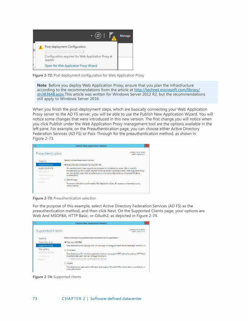
73 CHAPTER 2 | Software-defined datacenter
Figure 2-72: Post deployment configuration for Web Application Proxy
Note Before you deploy Web Application Proxy, ensure that you plan the infrastructure according to the recommendations from the article at http://technet.microsoft.com/library/ dn383648.aspx.This article was written for Windows Server 2012 R2, but the recommendations still apply to Windows Server 2016.
When you finish the post-deployment steps, which are basically connecting your Web Application
Proxy server to the AD FS server, you will be able to use the Publish New Application Wizard. You will
notice some changes that were introduced in this new version. The first change you will notice when
you click Publish under the Web Application Proxy management tool are the options available in the
left pane. For example, on the Preauthentication page, you can choose either Active Directory
Federation Services (AD FS) or Pass-Through for the preauthentication method, as shown in
Figure 2-73.
Figure 2-73: Preauthentication selection
For the purpose of this example, select Active Directory Federation Services (AD FS) as the
preauthentication method, and then click Next. On the Supported Clients page, your options are
Web And MSOFBA, HTTP Basic, or OAuth2, as depicted in Figure 2-74.
Figure 2-74: Supported clients

74 CHAPTER 2 | Software-defined datacenter
You can use the Web and MSOFBA option to preauthenticate clients by using the Microsoft Office
Forms Based Authentication (MSOFBA) protocol. MSOFBA provides form-based authentication
instead of basic or NTLM authentication when you use Office client applications. The second option is
the well-known HTTP basic authentication that you can use in scenarios such as Exchange Active Sync
(ActiveSync). This is a new capability included in this release of Web Application Proxy. For the
ActiveSync scenario, the authentication process includes four core steps:
1. WAP stops the request and passes all credentials to AD FS.
2. AD FS validates, applies policy, and replies with a token.
3. Upon success, Web Application Proxy allows the request to pass to the Exchange server.
4. Web Application Proxy caches the token for future use.
The third option is OAuth2, which is an authorization framework that many vendors use, including
Microsoft. Web Application Proxy has supported OAuth2 since Windows Server 2012 R2; however, the
option was not available in the user interface (UI).
More info To learn more about OAuth2, go to http://tools.ietf.org/html/rfc6749. You can find additional information about AD FS support for OAuth2 at http://technet.microsoft.com/ library/dn383640.aspx.
After you select the appropriate client for the publication, click Next. The Publishing Settings page
includes one new option with which you can turn on HTTP-to-HTTPS redirection, as illustrated in
Figure 2-75.
Figure 2-75: Publishing settings
This is a great addition because to turn on HTTP-to-HTTPs redirection in Windows Server 2012 R2,
you were required to install and configure Internet Information Services (IIS). Notice that this option is
selected by default, but ensure that it is selected for your app before clicking Next and moving on to
the Confirmation page.
Remote Desktop Gateway scenario
The changes that were first introduced in the Windows Server 2012 R2 August 2014 update package
regarding the way Web Application Proxy handles Remote Desktop Gateway publication is
incorporated in this release. This change simplifies the deployment experience for IT administrators
who are planning to publish RDP via Web Application Proxy and makes it possible for Remote
Desktop Gateway to pick up the session cookie that was used by Remote Desktop Web Access to
authenticate the RDP over HTTP traffic.
75 CHAPTER 2 | Software-defined datacenter
Auditing access to resources
Windows Server 2016 introduces a new capability that gives IT administrators better audit access to
published resources. Web Application Proxy now adds to every request an X-Forwarded-For (XFF)
header to verify whether the header already exists. If so, Web Application Proxy concatenates the
client IP to this header.
Note XFF is a nonstandard HTTP header that became the de facto standard. It is used extensively by proxy servers to identify the IP of an originated request. For more information about this, read the RFC at http://tools.ietf.org/html/rfc7239.
Another important aspect of Web Application Proxy auditing capabilities are the events that are
logged in the Event Viewer. In this release, the Event Viewer includes many more events, such as
analytics and debug logs. You will review some examples of these events in the section "Web
Application Proxy troubleshooting" later in this chapter.
Taking application proxies to the modern IT world
A few years ago, our team had a big dilemma. We had two products in the market: Forefront Threat Management Gateway and Forefront Unified Access Gateway. Both of these products had been around for many years and had been deployed by tens of thousands of customers. Both of them had evolved since they were first introduced during the 1990s.
However, both products had similar issues: They were very complex products that were difficult to deploy, troubleshoot, and maintain. This was partly because over the years they accumulated many capabilities that became irrelevant. At the same time, they lacked or had limited support for modern technologies such as federation and OAuth2. On top of it all, they were expensive products that had their own licenses.
It was a tough decision, but we decided to start from a blank page, to examine all the functionality of reverse proxy, to pick and choose only the technologies that matter today, and to implement them by using a fresh code base built on the most modern standards. A big part of this decision was that we wanted to embed the reverse proxy into Windows Server. We wanted to make it just like any other role service available to install from Server Manager. For us, this meant adhering to the strictest standards regarding code and management. Microsoft customers expect that all Windows Server role services are managed the same way, including in Windows PowerShell, the administrator UI, the remote administrator UI, performance counters, the System Center Operations Manager pack, event logs, and so on.
This is how Web Application Proxy was born in Windows Server 2012 R2. We made no compromise on code security, management, and standardization. And, we were happy that customers got it. Companies were able to deploy and integrate Web Application Proxy into their infrastructure very easily.
The downside of this approach is that we were not able to include all of the functionality we wanted to have—functionality that would make it possible for all customers to move from Threat Management Gateway and Unified Access Gateway to the new solution. However, now that we have built a solid foundation, it is easier to add more functionality to make Web Application Proxy the obvious choice to publish on-premises resources such as Microsoft SharePoint, Lync, and Exchange to remote users. This version marks an important milestone in the journey we began quite a few years ago.
Now, it is time for us to begin another journey to bring remote access to the cloud era. We have created Azure Active Directory Application Proxy as another tool for customers to publish applications in cloud-based solutions. Fortunately, Web Application Proxy in Windows Server and Azure Active Directory Application Proxy share a lot of code. More than that, they share the same concepts and perception of remote access and how to make it simple to deploy and easy to maintain.

76 CHAPTER 2 | Software-defined datacenter
Going forward, we will continue to develop both products. We plan to offer Microsoft customers a choice with regard to which architecture to use. The cloud offers users a unique and highly efficient way to implement remote access utilizing the rich functionality and robust security mechanisms of Azure Active Directory, without the need to change their perimeter network. The same service that takes care of 18 billion authentication requests per week handles your on-premises applications.
Meir Mendelovich, Senior Program Manager
Publishing Exchange Server 2013
As noted earlier, the retirement of Forefront Threat Management Gateway left a number of Exchange
administrators in a quandary about how to publish their Exchange server to the Internet. Although
large organizations can generally take advantage of an existing hardware load balancer infrastructure
to accomplish this task, small- and medium-sized businesses might not have the funds or expertise to
manage a load balancer. This is where the Web Application Server role can be very useful.
The basic principles for publishing Exchange 2013 Outlook Web App and the Exchange Admin Center
through Web Application Proxy are outlined in detail at http://technet.microsoft.com/library/
dn635116(v=exchg.150).aspx. However, to get a better understanding of some of the capabilities of
Web Application Proxy on Windows Server 2016, consider the very simple scenario illustrated in
Figure 2-76.
Figure 2-76: A scenario demonstrating Web Application Proxy on Windows Server 2016
In this scenario, a user on a nondomain-joined machine named CLT01 will be connecting to Outlook
Web App by using the URL https://mail.contoso.com/owa. The user’s request is sent over the external
network to a Routing and Remote Access Server (RRAS01), which provides external DNS resolution for
the zone contoso.com and routes traffic to the Contoso internal network for outside users. RRAS01
routes the request for https://mail.contoso.com/owa into Contoso’s internal network to the Web
Application Proxy server (WAP01), which is running Windows Server 2016.
On WAP01, Outlook Web App has been published using AD FS preauthentication. In fact, a number of
different Exchange services have been published using AD FS preauthentication or pass-through
authentication, as demonstrated in Figure 2-77.

77 CHAPTER 2 | Software-defined datacenter
Figure 2-77: Published web applications
In this case, we are assuming that this is a split DNS configuration and that internal and external DNS
resolve the name mail.contoso.com to different IP addresses, depending on the user’s location. Thus,
the External URL value and Backend Server URL value are the same, but they could be different, as
we’ll show later. So, when a user who is on the internal Contoso network goes to
https://mail.contoso.com/owa, authentication takes place by using Windows Integrated
Authentication. This requires that the URLs for mail.contoso.com and adfs.contoso.com are defined in
the Trusted Zone for Local Intranet in Internet Explorer. If that is done, the user should be able to
connect to his mailbox and not be prompted for authentication at all.
On the other hand, a user connecting from outside the corporate network is presented with a form-
based authentication webpage, such as that shown in Figure 2-78, and is required to provide sign-in
credentials.
Figure 2-78: A form-based authentication page
However, one very important service used extensively in nearly every organization is missing—
Microsoft Server ActiveSync. You could define a relying party trust for ActiveSync and set it up for
pass-through authentication; this is what you would have done in Windows Server 2012 R2 Web
Application Proxy. But, as noted earlier in this chapter, Web Application Proxy in Windows Server 2016
now supports the use of HTTP Basic clients for services such as ActiveSync that don’t support
redirection and that use HTTP Basic to authenticate users.
HTTP Basic is the authorization method used by many protocols, including ActiveSync, to connect rich
clients, including smartphones, with an Exchange mailbox. (For more information on HTTP Basic, see
RFC 2617 at http://www.ietf.org/rfc/rfc2617.txt.) Web Application Proxy traditionally interacts with AD
FS using redirections, which is not supported on ActiveSync clients. Publishing an app by using HTTP
Basic provides support for ActiveSync clients in Web Application Proxy by making it possible for the
HTTP app to receive a nonclaims relying party trust for the application to AD FS.
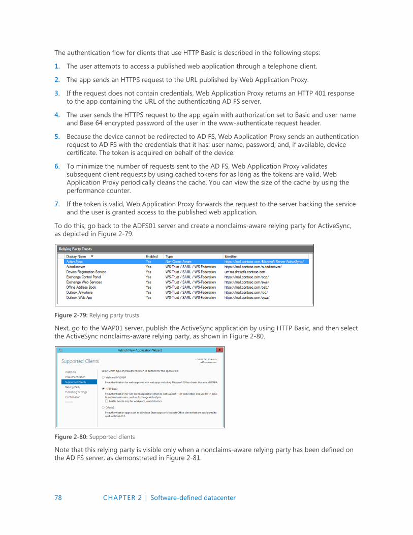
78 CHAPTER 2 | Software-defined datacenter
The authentication flow for clients that use HTTP Basic is described in the following steps:
1. The user attempts to access a published web application through a telephone client.
2. The app sends an HTTPS request to the URL published by Web Application Proxy.
3. If the request does not contain credentials, Web Application Proxy returns an HTTP 401 response
to the app containing the URL of the authenticating AD FS server.
4. The user sends the HTTPS request to the app again with authorization set to Basic and user name
and Base 64 encrypted password of the user in the www-authenticate request header.
5. Because the device cannot be redirected to AD FS, Web Application Proxy sends an authentication
request to AD FS with the credentials that it has: user name, password, and, if available, device
certificate. The token is acquired on behalf of the device.
6. To minimize the number of requests sent to the AD FS, Web Application Proxy validates
subsequent client requests by using cached tokens for as long as the tokens are valid. Web
Application Proxy periodically cleans the cache. You can view the size of the cache by using the
performance counter.
7. If the token is valid, Web Application Proxy forwards the request to the server backing the service
and the user is granted access to the published web application.
To do this, go back to the ADFS01 server and create a nonclaims-aware relying party for ActiveSync,
as depicted in Figure 2-79.
Figure 2-79: Relying party trusts
Next, go to the WAP01 server, publish the ActiveSync application by using HTTP Basic, and then select
the ActiveSync nonclaims-aware relying party, as shown in Figure 2-80.
Figure 2-80: Supported clients
Note that this relying party is visible only when a nonclaims-aware relying party has been defined on
the AD FS server, as demonstrated in Figure 2-81.

79 CHAPTER 2 | Software-defined datacenter
Figure 2-81: Relying party options
Complete the remainder of the wizard, configuring the external and server URL backing the service.
The end result is shown in Figure 2-82.
Figure 2-82: All published web applications
Notice that the Microsoft ActiveSync published application uses the AD FS For Rich Clients
preauthentication method.
Defining the claims
Although defining claims isn’t a function of the Web Application Proxy role in Windows Server 2016,
it’s important to understand the role that claims play in a transaction. Claims are defined in the
Outlook Web App section of the Actions pane on the AD FS server, as shown in Figure 2-83.
Figure 2-83: Editing claim rules
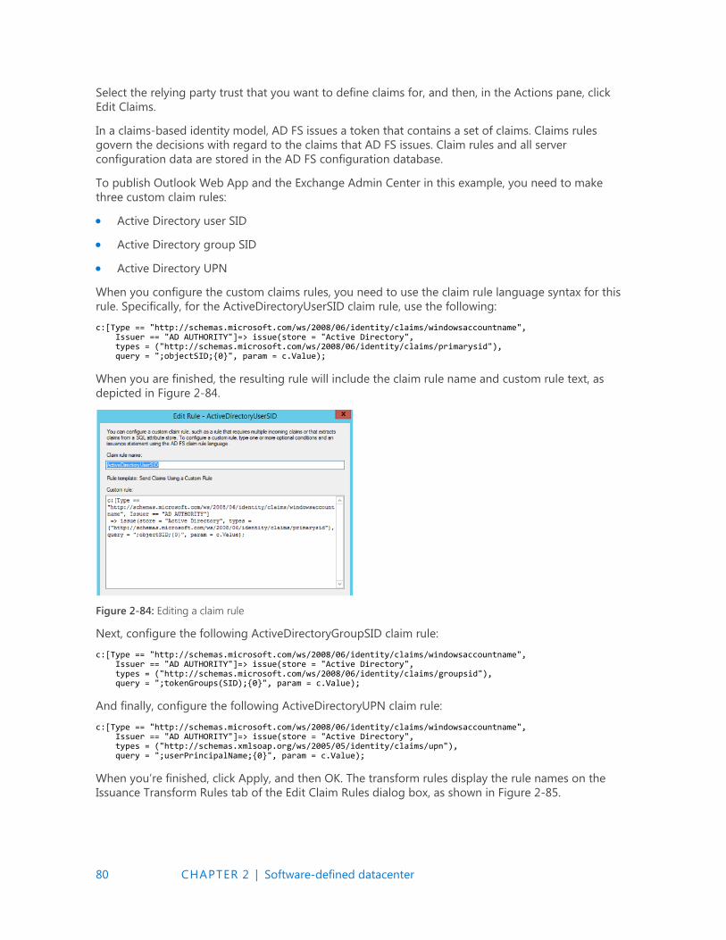
80 CHAPTER 2 | Software-defined datacenter
Select the relying party trust that you want to define claims for, and then, in the Actions pane, click
Edit Claims.
In a claims-based identity model, AD FS issues a token that contains a set of claims. Claims rules
govern the decisions with regard to the claims that AD FS issues. Claim rules and all server
configuration data are stored in the AD FS configuration database.
To publish Outlook Web App and the Exchange Admin Center in this example, you need to make
three custom claim rules:
Active Directory user SID
Active Directory group SID
Active Directory UPN
When you configure the custom claims rules, you need to use the claim rule language syntax for this
rule. Specifically, for the ActiveDirectoryUserSID claim rule, use the following:
c:[Type == "http://schemas.microsoft.com/ws/2008/06/identity/claims/windowsaccountname", Issuer == "AD AUTHORITY"]=> issue(store = "Active Directory", types = ("http://schemas.microsoft.com/ws/2008/06/identity/claims/primarysid"), query = ";objectSID;{0}", param = c.Value);
When you are finished, the resulting rule will include the claim rule name and custom rule text, as
depicted in Figure 2-84.
Figure 2-84: Editing a claim rule
Next, configure the following ActiveDirectoryGroupSID claim rule:
c:[Type == "http://schemas.microsoft.com/ws/2008/06/identity/claims/windowsaccountname", Issuer == "AD AUTHORITY"]=> issue(store = "Active Directory", types = ("http://schemas.microsoft.com/ws/2008/06/identity/claims/groupsid"), query = ";tokenGroups(SID);{0}", param = c.Value);
And finally, configure the following ActiveDirectoryUPN claim rule:
c:[Type == "http://schemas.microsoft.com/ws/2008/06/identity/claims/windowsaccountname", Issuer == "AD AUTHORITY"]=> issue(store = "Active Directory", types = ("http://schemas.xmlsoap.org/ws/2005/05/identity/claims/upn"), query = ";userPrincipalName;{0}", param = c.Value);
When you’re finished, click Apply, and then OK. The transform rules display the rule names on the
Issuance Transform Rules tab of the Edit Claim Rules dialog box, as shown in Figure 2-85.

81 CHAPTER 2 | Software-defined datacenter
Figure 2-85: The Edit Claim Rules dialog box
Note You will need to do this for each of your relying party trusts.
URL hostname translation
Another thing to keep in mind is that Web Application Proxy can translate host names in URLs.
For example, you might have an application that your external users access by using the URL
http://www.contoso.com/app01, whereas your internal users get to the same app by going to
http://apps.contoso.com/app01. This is perfectly acceptable, and Web Application Proxy can
handle the difference in the URL, as illustrated by Figure 2-86, in which the external URL is
http://www.contoso.com/app01 and the Backend Server URL is http://apps.contoso.com/app01.
Figure 2-86: Published web applications
Note You cannot change the path to be http://www.contoso.com/app1 externally and http://apps.contoso.com/applicationXYZ internally.
This is valuable to know when publishing Exchange, because you can have different DNS namespaces
for internal and external access. Therefore, you might want to publish a URL for Outlook Web App
that is different for your internal users than the one you publish for external access. Figure 2-87 shows
that Web Application Proxy can accommodate this need as long as you keep the same path name.
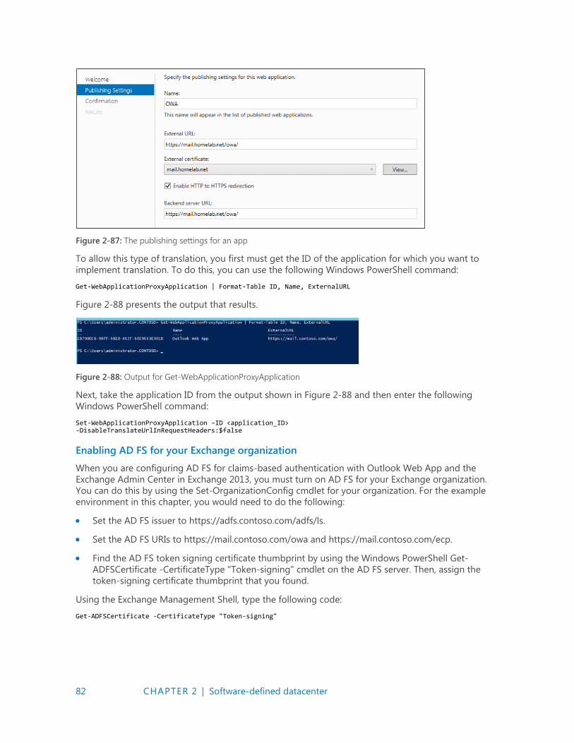
82 CHAPTER 2 | Software-defined datacenter
Figure 2-87: The publishing settings for an app
To allow this type of translation, you first must get the ID of the application for which you want to
implement translation. To do this, you can use the following Windows PowerShell command:
Get-WebApplicationProxyApplication | Format-Table ID, Name, ExternalURL
Figure 2-88 presents the output that results.
Figure 2-88: Output for Get-WebApplicationProxyApplication
Next, take the application ID from the output shown in Figure 2-88 and then enter the following
Windows PowerShell command:
Set-WebApplicationProxyApplication –ID <application_ID> -DisableTranslateUrlInRequestHeaders:$false
Enabling AD FS for your Exchange organization
When you are configuring AD FS for claims-based authentication with Outlook Web App and the
Exchange Admin Center in Exchange 2013, you must turn on AD FS for your Exchange organization.
You can do this by using the Set-OrganizationConfig cmdlet for your organization. For the example
environment in this chapter, you would need to do the following:
Set the AD FS issuer to https://adfs.contoso.com/adfs/ls.
Set the AD FS URIs to https://mail.contoso.com/owa and https://mail.contoso.com/ecp.
Find the AD FS token signing certificate thumbprint by using the Windows PowerShell Get-
ADFSCertificate -CertificateType "Token-signing" cmdlet on the AD FS server. Then, assign the
token-signing certificate thumbprint that you found.
Using the Exchange Management Shell, type the following code:
Get-ADFSCertificate -CertificateType "Token-signing"
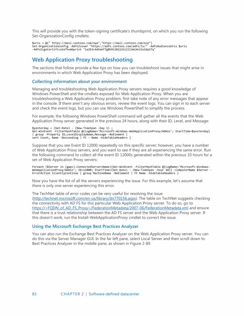
83 CHAPTER 2 | Software-defined datacenter
This will provide you with the token-signing certificate’s thumbprint, on which you run the following
Set-OrganizationConfig cmdlets:
$uris = @(" https://mail.contoso.com/owa","https://mail.contoso.com/ecp") Set-OrganizationConfig -AdfsIssuer "https://adfs.contoso.com/adfs/ls/" -AdfsAudienceUris $uris –AdfsSignCertificateThumbprint "1a2b3c4d5e6f7g8h9i10j11k12l13m14n15o16p17q"
Web Application Proxy troubleshooting
The sections that follow provide a few tips on how you can troubleshoot issues that might arise in
environments in which Web Application Proxy has been deployed.
Collecting information about your environment
Managing and troubleshooting Web Application Proxy servers requires a good knowledge of
Windows PowerShell and the cmdlets exposed for Web Application Proxy. When you are
troubleshooting a Web Application Proxy problem, first take note of any error messages that appear
in the console. If there aren’t any obvious errors, review the event logs. You can sign in to each server
and check the event logs, but you can use Windows PowerShell to simplify the process.
For example, the following Windows PowerShell command will gather all the events that the Web
Application Proxy server generated in the previous 24 hours, along with their ID, Level, and Message:
$yesterday = (Get-Date) - (New-TimeSpan -Day 1) ; Get-WinEvent -FilterHashTable @{LogName='Microsoft-Windows-WebApplicationProxy/Admin'; StartTime=$yesterday} | group -Property ID,LevelDisplayName,Message -NoElement | sort Count, Name -Descending | ft – Name -HideTableHeaders }
Suppose that you see Event ID 12000 repeatedly on this specific server; however, you have a number
of Web Application Proxy servers, and you want to see if they are all experiencing the same error. Run
the following command to collect all the event ID 12000s generated within the previous 10 hours for a
set of Web Application Proxy servers:
Foreach ($Server in (gwpc).ConnectedServersName){Get-WinEvent -FilterHashTable @{LogName='Microsoft-Windows-WebApplicationProxy/Admin'; ID=12000; StartTime=(Get-Date) - (New-TimeSpan -hour 10)} -ComputerName $Server -ErrorAction SilentlyContinue | group MachineName -NoElement | ft Name -HideTableHeaders }
Now you have the list of all the servers experiencing the issue. For this example, let’s assume that
there is only one server experiencing this error.
The TechNet table of error codes can be very useful for resolving the issue
(http://technet.microsoft.com/en-us/library/dn770156.aspx). The table on TechNet suggests checking
the connectivity with AD FS for this particular Web Application Proxy server. To do so, go to
https://<FQDN_of_AD_FS_Proxy>/FederationMetadata/2007-06/FederationMetadata.xml and ensure
that there is a trust relationship between the AD FS server and the Web Application Proxy server. If
this doesn’t work, run the Install-WebApplicationProxy cmdlet to correct the issue.
Using the Microsoft Exchange Best Practices Analyzer
You can also run the Exchange Best Practices Analyzer on the Web Application Proxy server. You can
do this via the Server Manager GUI. In the far left pane, select Local Server and then scroll down to
Best Practices Analyzer in the middle pane, as shown in Figure 2-89.
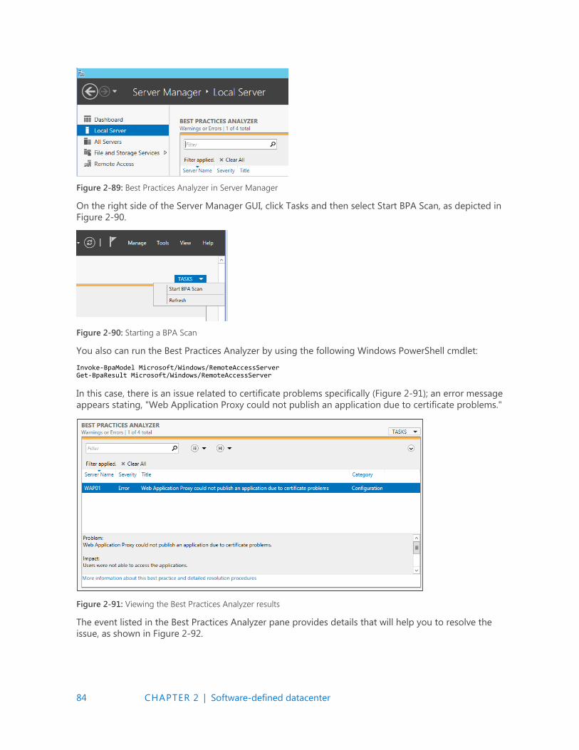
84 CHAPTER 2 | Software-defined datacenter
Figure 2-89: Best Practices Analyzer in Server Manager
On the right side of the Server Manager GUI, click Tasks and then select Start BPA Scan, as depicted in
Figure 2-90.
Figure 2-90: Starting a BPA Scan
You also can run the Best Practices Analyzer by using the following Windows PowerShell cmdlet:
Invoke-BpaModel Microsoft/Windows/RemoteAccessServer Get-BpaResult Microsoft/Windows/RemoteAccessServer
In this case, there is an issue related to certificate problems specifically (Figure 2-91); an error message
appears stating, "Web Application Proxy could not publish an application due to certificate problems."
Figure 2-91: Viewing the Best Practices Analyzer results
The event listed in the Best Practices Analyzer pane provides details that will help you to resolve the
issue, as shown in Figure 2-92.
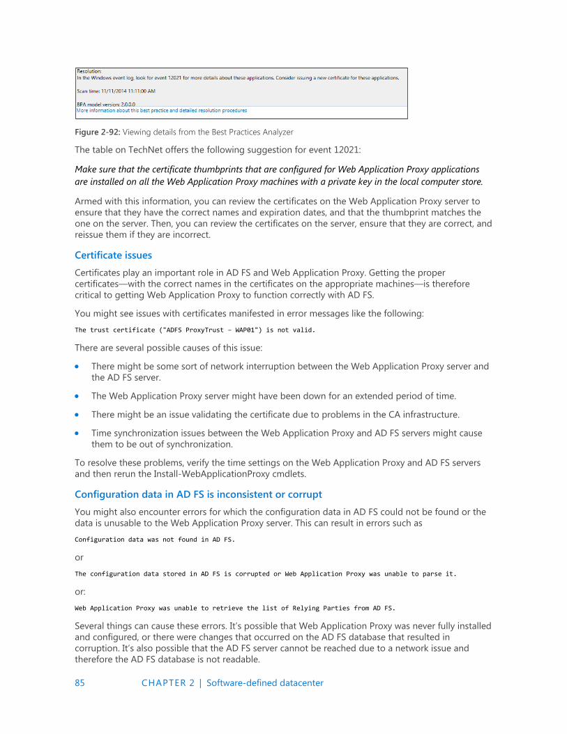
85 CHAPTER 2 | Software-defined datacenter
Figure 2-92: Viewing details from the Best Practices Analyzer
The table on TechNet offers the following suggestion for event 12021:
Make sure that the certificate thumbprints that are configured for Web Application Proxy applications
are installed on all the Web Application Proxy machines with a private key in the local computer store.
Armed with this information, you can review the certificates on the Web Application Proxy server to
ensure that they have the correct names and expiration dates, and that the thumbprint matches the
one on the server. Then, you can review the certificates on the server, ensure that they are correct, and
reissue them if they are incorrect.
Certificate issues
Certificates play an important role in AD FS and Web Application Proxy. Getting the proper
certificates—with the correct names in the certificates on the appropriate machines—is therefore
critical to getting Web Application Proxy to function correctly with AD FS.
You might see issues with certificates manifested in error messages like the following:
The trust certificate ("ADFS ProxyTrust – WAP01") is not valid.
There are several possible causes of this issue:
There might be some sort of network interruption between the Web Application Proxy server and
the AD FS server.
The Web Application Proxy server might have been down for an extended period of time.
There might be an issue validating the certificate due to problems in the CA infrastructure.
Time synchronization issues between the Web Application Proxy and AD FS servers might cause
them to be out of synchronization.
To resolve these problems, verify the time settings on the Web Application Proxy and AD FS servers
and then rerun the Install-WebApplicationProxy cmdlets.
Configuration data in AD FS is inconsistent or corrupt
You might also encounter errors for which the configuration data in AD FS could not be found or the
data is unusable to the Web Application Proxy server. This can result in errors such as
Configuration data was not found in AD FS.
or
The configuration data stored in AD FS is corrupted or Web Application Proxy was unable to parse it.
or:
Web Application Proxy was unable to retrieve the list of Relying Parties from AD FS.
Several things can cause these errors. It’s possible that Web Application Proxy was never fully installed
and configured, or there were changes that occurred on the AD FS database that resulted in
corruption. It’s also possible that the AD FS server cannot be reached due to a network issue and
therefore the AD FS database is not readable.

86 CHAPTER 2 | Software-defined datacenter
There are several paths to resolution for these types of errors:
Run the Install-WebApplicationProxy cmdlet again to clear up configuration issues.
Confirm network connectivity to the AD FS server from the Web Application Proxy server.
Verify that the WebApplicationProxy service is running on the Web Application Proxy server.
Supporting non–SPI-capable clients
Server Name Indication (SNI) is a feature of Secure Sockets Layer (SSL) Transport Layer Security (TLS)
that is used in Web Application Proxy server and AD FS to reduce network infrastructure
requirements. Traditionally, an SSL certificate had to be bound to an IP address/port combination. This
meant that you would need to have a separate IP address configured if you wanted to bind a different
certificate to the same port number on a server. With the use of SNI, a certificate is instead bound to
the host name and port, allowing you to conserve IP addresses and reduce complexity.
It’s important to realize that SNI relies on the requesting client supporting SNI. If the SSL Client Hello
doesn’t contain the SNI header, http.sys won’t be able to determine which certificate to offer the client
and will reset the connection.
Most modern clients support SNI, but there are some clients that tend to cause issues. Generally,
older browsers, legacy operating systems, hardware load balancers, health probes, older versions of
WebDAV, ActiveSync on Android, and some older VoIP conferencing devices might be non–SNI-
capable devices.
If it is necessary to support non-SNI clients, the easiest solution is to create a fallback certificate
binding in http.sys. The fallback certificate needs to include any fully qualified domain names (FQDNs)
that may need to be supported, including the FQDN for the AD FS service itself (adfs.contoso.com),
the FQDN of any applications published via Web Application Proxy (mail.contoso.com), and the FQDN
to support Enterprise registration (enterpriseregsitration.contoso.com) if you are using Workplace
Join.
When you have generated the certificate, get the application GUID and certificate thumbprints in use
by using the following Windows PowerShell cmdlet:
Get-WebApplicationProxyApplication | fl Name,ExternalURL,ExternalCertificateThumbprint
Now that you have the application GUID and certificate thumbprint, you can bind it to the IP wildcard
and port 443 by using the following syntax:
netsh http add sslcert ipport=0.0.0.0:443 certhash=certthumprint appid={applicationguid}
Note that you will need to run this on each server in the AD FS farm as well as on any Web
Application Proxy server.
More info You can find technical details on SNI as a subsection of the TLS Extensions RFC at https://tools.ietf.org/html/rfc3546#section-3.1.

Get the latest news from Microsoft Press sent to your inbox.
• New and upcoming books
• Specialoffers
• Free eBooks
• How-to articles
Sign up today at MicrosoftPressStore.com/Newsletters
Hear aboutit first.
87 CHAPTER 3 | Application platform
C H A P T E R
3
Application platform In this chapter, we explore how Microsoft has made a focused shift to
ensuring that customers today, whether they are in the public or private
cloud, have a solid foundation for their application portfolio. We discuss
two new technologies introduced in Microsoft Windows Server 2016:
Nano Server and containers. With these new technologies, you can take
advantage of a highly optimized, scalable, and secure experience for
Application Platform.
Modernizing traditional apps The cloud makes it possible for businesses to innovate quickly and deliver faster time-to-value with
cloud-native applications and microservices architecture. But most businesses are grappling with how
to manage and update thousands of existing applications while planning how to move to this new
world. What is needed is a solution that helps you invigorate existing applications and create new,
cloud-native applications. Windows Server 2016 can do both.
Windows Server helps you to secure and modernize existing enterprise server apps with little or no
code changes; package existing apps in containers to realize the benefit of a more agile DevOps
model; and then deploy either on-premises, to any cloud, or in a hybrid model. Developers can create
cloud-ready, business-changing apps and services, whether on-premises or in any cloud, using
technologies such as containers and the lightweight Nano Server installation option.
Windows Server 2016 can help you modernize your apps and innovate faster with a cloud-ready
application platform. Figure 3-1 highlights the areas where you can take advantage of the technology
today in Windows Server 2016 to move forward and be cloud ready or cloud native.
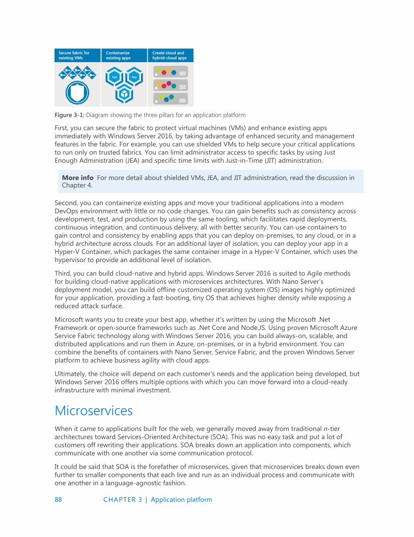
88 CHAPTER 3 | Application platform
Figure 3-1: Diagram showing the three pillars for an application platform
First, you can secure the fabric to protect virtual machines (VMs) and enhance existing apps
immediately with Windows Server 2016, by taking advantage of enhanced security and management
features in the fabric. For example, you can use shielded VMs to help secure your critical applications
to run only on trusted fabrics. You can limit administrator access to specific tasks by using Just
Enough Administration (JEA) and specific time limits with Just-in-Time (JIT) administration.
More info For more detail about shielded VMs, JEA, and JIT administration, read the discussion in Chapter 4.
Second, you can containerize existing apps and move your traditional applications into a modern
DevOps environment with little or no code changes. You can gain benefits such as consistency across
development, test, and production by using the same tooling, which facilitates rapid deployments,
continuous integration, and continuous delivery, all with better security. You can use containers to
gain control and consistency by enabling apps that you can deploy on-premises, to any cloud, or in a
hybrid architecture across clouds. For an additional layer of isolation, you can deploy your app in a
Hyper-V Container, which packages the same container image in a Hyper-V Container, which uses the
hypervisor to provide an additional level of isolation.
Third, you can build cloud-native and hybrid apps. Windows Server 2016 is suited to Agile methods
for building cloud-native applications with microservices architectures. With Nano Server’s
deployment model, you can build offline customized operating system (OS) images highly optimized
for your application, providing a fast-booting, tiny OS that achieves higher density while exposing a
reduced attack surface.
Microsoft wants you to create your best app, whether it’s written by using the Microsoft .Net
Framework or open-source frameworks such as .Net Core and Node.JS. Using proven Microsoft Azure
Service Fabric technology along with Windows Server 2016, you can build always-on, scalable, and
distributed applications and run them in Azure, on-premises, or in a hybrid environment. You can
combine the benefits of containers with Nano Server, Service Fabric, and the proven Windows Server
platform to achieve business agility with cloud apps.
Ultimately, the choice will depend on each customer’s needs and the application being developed, but
Windows Server 2016 offers multiple options with which you can move forward into a cloud-ready
infrastructure with minimal investment.
Microservices
When it came to applications built for the web, we generally moved away from traditional n-tier
architectures toward Services-Oriented Architecture (SOA). This was no easy task and put a lot of
customers off rewriting their applications. SOA breaks down an application into components, which
communicate with one another via some communication protocol.
It could be said that SOA is the forefather of microservices, given that microservices breaks down even
further to smaller components that each live and run as an individual process and communicate with
one another in a language-agnostic fashion.
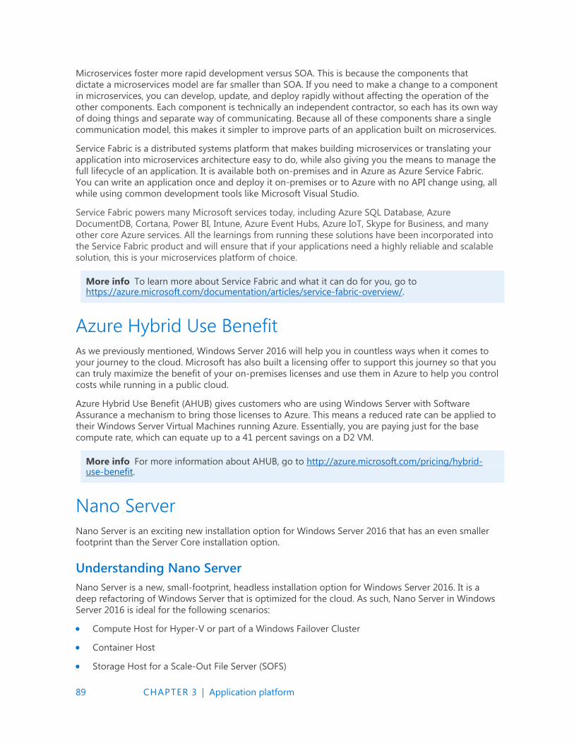
89 CHAPTER 3 | Application platform
Microservices foster more rapid development versus SOA. This is because the components that
dictate a microservices model are far smaller than SOA. If you need to make a change to a component
in microservices, you can develop, update, and deploy rapidly without affecting the operation of the
other components. Each component is technically an independent contractor, so each has its own way
of doing things and separate way of communicating. Because all of these components share a single
communication model, this makes it simpler to improve parts of an application built on microservices.
Service Fabric is a distributed systems platform that makes building microservices or translating your
application into microservices architecture easy to do, while also giving you the means to manage the
full lifecycle of an application. It is available both on-premises and in Azure as Azure Service Fabric.
You can write an application once and deploy it on-premises or to Azure with no API change using, all
while using common development tools like Microsoft Visual Studio.
Service Fabric powers many Microsoft services today, including Azure SQL Database, Azure
DocumentDB, Cortana, Power BI, Intune, Azure Event Hubs, Azure IoT, Skype for Business, and many
other core Azure services. All the learnings from running these solutions have been incorporated into
the Service Fabric product and will ensure that if your applications need a highly reliable and scalable
solution, this is your microservices platform of choice.
More info To learn more about Service Fabric and what it can do for you, go to https://azure.microsoft.com/documentation/articles/service-fabric-overview/.
Azure Hybrid Use Benefit
As we previously mentioned, Windows Server 2016 will help you in countless ways when it comes to
your journey to the cloud. Microsoft has also built a licensing offer to support this journey so that you
can truly maximize the benefit of your on-premises licenses and use them in Azure to help you control
costs while running in a public cloud.
Azure Hybrid Use Benefit (AHUB) gives customers who are using Windows Server with Software
Assurance a mechanism to bring those licenses to Azure. This means a reduced rate can be applied to
their Windows Server Virtual Machines running Azure. Essentially, you are paying just for the base
compute rate, which can equate up to a 41 percent savings on a D2 VM.
More info For more information about AHUB, go to http://azure.microsoft.com/pricing/hybrid-use-benefit.
Nano Server
Nano Server is an exciting new installation option for Windows Server 2016 that has an even smaller
footprint than the Server Core installation option.
Understanding Nano Server
Nano Server is a new, small-footprint, headless installation option for Windows Server 2016. It is a
deep refactoring of Windows Server that is optimized for the cloud. As such, Nano Server in Windows
Server 2016 is ideal for the following scenarios:
Compute Host for Hyper-V or part of a Windows Failover Cluster
Container Host
Storage Host for a Scale-Out File Server (SOFS)
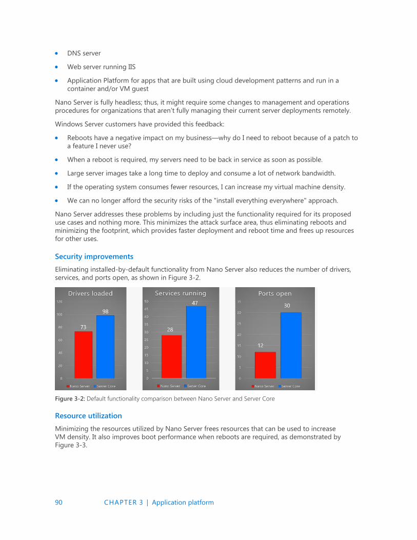
90 CHAPTER 3 | Application platform
DNS server
Web server running IIS
Application Platform for apps that are built using cloud development patterns and run in a
container and/or VM guest
Nano Server is fully headless; thus, it might require some changes to management and operations
procedures for organizations that aren’t fully managing their current server deployments remotely.
Windows Server customers have provided this feedback:
Reboots have a negative impact on my business—why do I need to reboot because of a patch to
a feature I never use?
When a reboot is required, my servers need to be back in service as soon as possible.
Large server images take a long time to deploy and consume a lot of network bandwidth.
If the operating system consumes fewer resources, I can increase my virtual machine density.
We can no longer afford the security risks of the "install everything everywhere" approach.
Nano Server addresses these problems by including just the functionality required for its proposed
use cases and nothing more. This minimizes the attack surface area, thus eliminating reboots and
minimizing the footprint, which provides faster deployment and reboot time and frees up resources
for other uses.
Security improvements
Eliminating installed-by-default functionality from Nano Server also reduces the number of drivers,
services, and ports open, as shown in Figure 3-2.
Figure 3-2: Default functionality comparison between Nano Server and Server Core
Resource utilization
Minimizing the resources utilized by Nano Server frees resources that can be used to increase
VM density. It also improves boot performance when reboots are required, as demonstrated by
Figure 3-3.
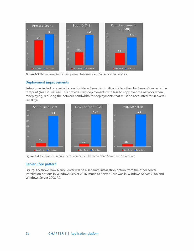
91 CHAPTER 3 | Application platform
Figure 3-3: Resource utilization comparison between Nano Server and Server Core
Deployment improvements
Setup time, including specialization, for Nano Server is significantly less than for Server Core, as is the
footprint (see Figure 3-4). This provides fast deployments with less to copy over the network when
redeploying, reducing the network bandwidth for deployments that must be accounted for in overall
capacity.
Figure 3-4: Deployment requirements comparison between Nano Server and Server Core
Server Core pattern
Figure 3-5 shows how Nano Server will be a separate installation option from the other server
installation options in Windows Server 2016, much as Server Core was in Windows Server 2008 and
Windows Server 2008 R2.
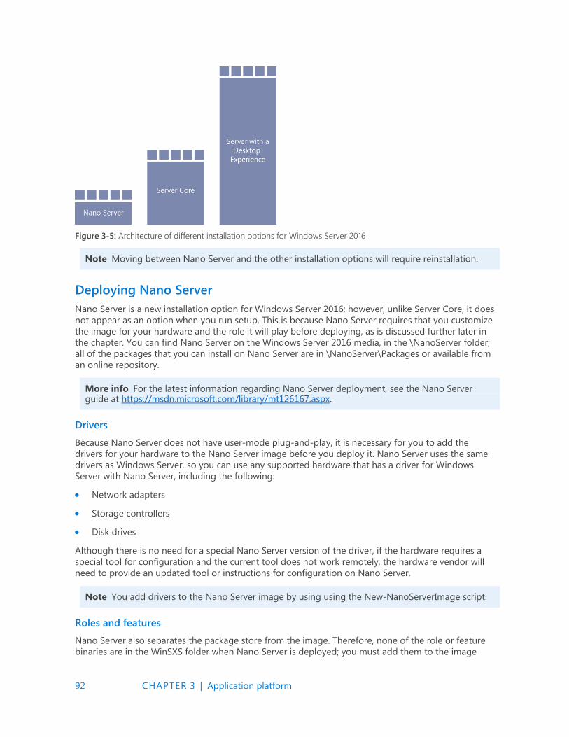
92 CHAPTER 3 | Application platform
Figure 3-5: Architecture of different installation options for Windows Server 2016
Note Moving between Nano Server and the other installation options will require reinstallation.
Deploying Nano Server
Nano Server is a new installation option for Windows Server 2016; however, unlike Server Core, it does
not appear as an option when you run setup. This is because Nano Server requires that you customize
the image for your hardware and the role it will play before deploying, as is discussed further later in
the chapter. You can find Nano Server on the Windows Server 2016 media, in the \NanoServer folder;
all of the packages that you can install on Nano Server are in \NanoServer\Packages or available from
an online repository.
More info For the latest information regarding Nano Server deployment, see the Nano Server guide at https://msdn.microsoft.com/library/mt126167.aspx.
Drivers
Because Nano Server does not have user-mode plug-and-play, it is necessary for you to add the
drivers for your hardware to the Nano Server image before you deploy it. Nano Server uses the same
drivers as Windows Server, so you can use any supported hardware that has a driver for Windows
Server with Nano Server, including the following:
Network adapters
Storage controllers
Disk drives
Although there is no need for a special Nano Server version of the driver, if the hardware requires a
special tool for configuration and the current tool does not work remotely, the hardware vendor will
need to provide an updated tool or instructions for configuration on Nano Server.
Note You add drivers to the Nano Server image by using using the New-NanoServerImage script.
Roles and features
Nano Server also separates the package store from the image. Therefore, none of the role or feature
binaries are in the WinSXS folder when Nano Server is deployed; you must add them to the image
93 CHAPTER 3 | Application platform
prior to deploying Nano Server. This makes it possible for you to configure the deployed Nano Server
image with just what is necessary for the role of the server.
Note You install roles and features by using the NewNanoServerImage cmdlet.
Additional roles will be added over time. You can check to validate what are the latest roles added to
Nano Server Support at https://msdn.microsoft.com/library/mt126167.aspx.
Applications
Nano Server has several proven scenarios as we have discussed, but what about running applications
on Nano Server as a guest VM or container workload? This would reduce the footprint required and
mitigate a broad number of potential security threats. The big question is how do we get an
application into Nano Server?
Remember, Nano Server is a deeply refactored version of Windows, and hence if there are
components that your application depends on (i.e., GUI components), not included in Nano Server, it
will not run and you will need to refactor the application to support Nano Server.
More info For some background reference, you can find a walkthrough example for developing an application on Nano Server at http://blogs.technet.microsoft.com/nanoserver/2016/04/27/ developing-native-apps-on-nano-server and https://blogs.technet.microsoft.com/ nanoserver/2016/04/27/nanoserverapiscan-exe-updated-for-tp5/.
If you have refactored your application to be compatible with Nano Server, you can use a new utility
called Windows Server Apps (WSA) Installer to help you package an APPX package and install this on
your Nano Server. APPX and WSA are a new framework for installing applications and overcoming
some of the limitations we had with MSI Installer.
More info To learn more about installing Windows Server applications on Nano Server, go to https://blogs.technet.microsoft.com/nanoserver/2015/11/18/installing-windows-server-apps-on-nano-server.
Specializing Nano Server
Just like Server Core, you can use a subset of what is available via Unattend to specialize a Nano
Server image. In an effort to further reduce the deployment time beyond just the smaller footprint, a
couple of commonly used Unattend settings are available to set offline:
Computer name
Domain join using Djoin.exe
More info For information on how to perform an offline domain join using Djoin.exe, see https://technet.microsoft.com/windows-server-docs/compute/nano-server/getting-started-with-nano-server.
When you deploy a Nano Server image with these settings configured in the offline section of the
Unattend file, Nano Server is specialized on first boot. This eliminates the second boot that occurs
with Server Core during specialization, further reducing deployment time.

94 CHAPTER 3 | Application platform
Remotely managing Nano Server
Nano Server is truly headless—there is no way to use Remote Desktop to connect remotely. As a
result, you must perform all Nano Server management remotely, either via Windows PowerShell,
Windows Management Instrumentation (WMI), Windows Remote Shell (WinRS), Emergency
Management Services (EMS), or remote GUI tools.
Note The options discussed in this section to remotely manage Nano Server are the same mechanisms that you can use to remotely manage Server Core. The only difference in managing Nano Server is that you must do it all remotely.
Windows PowerShell
Nano Server includes a refactored subset of Windows PowerShell called Core PowerShell, which is
based on the CoreCLR. Core PowerShell provides the following:
Full Windows PowerShell language compatibility
Full Windows PowerShell remoting
Most core engine features
Support for all cmdlet types, including C#, Windows PowerShell, and CIM
Because Nano Server includes Core PowerShell, it is possible to use Windows PowerShell Remoting to
manage Nano Server. To do so, you need to be an administrator on the Nano Server machine and add
its IP address to the management machine's trusted hosts. To do that, from an elevated Windows
PowerShell prompt, run the following command (which, for this example, assumes the Nano Server
machine’s IP address is 192.168.1.10):
PS C:\> Set-Item WSMan:\localhost\Client\TrustedHosts "192.168.1.10"
The following is an example of how to start an interactive remoting session:
PS C:\NanoServer> $ip = "192.168.1.10" PS C:\NanoServer> $user = "Administrator" PS C:\NanoServer> Enter-PSSession -ComputerName $ip -Credential $user
After you have done this, you can now run any available Windows PowerShell command as if you
were entering it directly into the Nano Server console; for example:
[192.168.1.10]: PS C:\users\user1\Documents> Get-Process w* [192.168.1.10]: PS C:\users\user1\Documents> ipconfig /all
Not all Windows PowerShell commands are available in Nano Server. To see which cmdlets are
available, run the following command:
[192.168.1.10]: PS C:\users\user1\Documents> Get-Command -CommandType Cmdlet
To end the remoting session, run this command:
[192.168.1.10]: PS C:\users\user1\Documents> Exit-PSSession
WMI
Nano Server includes WMI v1 and WMI v2 as well as the providers for the included functionality.
95 CHAPTER 3 | Application platform
WinRM
You can use CIM sessions and CIM instances in Windows PowerShell to run WMI commands remotely
over WinRM, as demonstrated here:
PS C:\NanoServer> $ip = "192.168.1.10" PS C:\NanoServer> $user = "Administrator" PS C:\NanoServer> $cim = New-CimSession –Credential $user –ComputerName $ip
When the CIM session is established, you can run various WMI commands, such as the following:
PS C:\NanoServer> Get-CimInstance –CimSession $cim –ClassName Win32_ComputerSystem | Format-List * PS C:\NanoServer> Get-CimInstance -Query "SELECT * from Win32_Process WHERE name LIKE 'p%'"
WinRS
Using Windows Remote Management (WinRM), you can run programs remotely. Before you can use
WinRS, you need to configure the WinRM service and set the code page, as follows:
C:\NanoServer> winrm quickconfig C:\NanoServer> winrm set winrm/config/client @{TrustedHosts="*"}
After you configure the WinRM service, you can run commands remotely, as if you were running them
from the command line:
C:\NanoServer> winrs –r:192.168.1.10 -u:Administrator -p:Tuva ipconfig
More info To learn more about about WinRS, go to http://technet.microsoft.com/library/ hh875630.aspx.
EMS
EMS is yet another tool that you can use to remotely manage Nano Server by connecting a serial
cable between the management machine and the Nano Server machine.
After you set up EMS in the Boot Configuration Data (BCD) settings for the Nano Server machine and
start Nano Server, start a terminal emulator, such as PuTTY, from an elevated prompt on the
management machine, and then complete the following steps:
1. Set the speed to the same baud rate you used in the Nano Server BCD.
2. Select Serial for Connection Type.
3. Enter the correct value for Serial Line.
Remote GUI tools
In addition to the command-line remote management options discussed in the previous sections, you
can use many existing remote GUI tools to remotely manage Nano Server. Because there is no local
sign-in or Remote Desktop in Nano Server and there are tools that even in Server Core don't have
remote GUI replacements, for example Task Manager, there are a set of web-based remote GUI called
Server Management Tools available in Azure today. You can use these web-based remote GUI tools to
manage Nano Server as well as Server Core and any of the other installation options.
More info For further information about the Server Management Tools, see Chapter 5.
96 CHAPTER 3 | Application platform
Monitoring Nano Server
You can now monitor Nano Server by using System Center 2016 Operations Manager. This will require
updated management packs, but it will be capable of monitoring the base Nano Server operating
system, Failover Clustering, DNS, and IIS. Support for other roles will come via new management
packs. The agent can be deployed remotely via the System Center 2016 Operations Manager Console.
Through the normal discovery wizard, you can push an agent to Nano Server. You also can configure
Nano Server to forward its security-related events to the Audit Collector Service in System Center
2016 Operations Manager.
Nano Server Recovery Console
Nano Server includes a Recovery Console that ensures you can access your Nano Server even if a
network misconfiguration interferes with connecting to the Nano Server. You can use the Recovery
Console to fix the network and then use your usual remote management tools.
When you boot Nano Server in either a VM or a physical computer that has a monitor and keyboard
attached, you'll see a full-screen, text-mode sign-in prompt. Sign in to this prompt with an
administrator account to see the computer name and IP address of the Nano Server. You can use the
following commands to navigate in this console:
Use arrow keys to scroll
Use Tab to move to any text that begins with “>”; then press Enter to select.
To go back one screen or page, press Esc. If you're on the home page, pressing ESC will log
you off.
Some screens have additional capabilities displayed on the last line of the screen. For example, if
you explore a network adapter, F4 will disable the network adapter.
Note The Recovery Console only supports basic keyboard functions. Keyboard lights, 10-key sections, and keyboard layout switching such as caps lock and number lock are not supported.
Service branching
In prior releases, Windows Server has been serviced and supported with a “5 + 5” model, meaning
that there is five years of mainstream support and five years of extended support, and this will
continue with Windows Server 2016. Customers that choose to install Windows Server 2016 with
desktop experience or Server Core will maintain this servicing experience, this is now known as the
Long-Term Servicing Branch (LTSB).
Customers choosing the Nano Server installation will opt into a more active servicing model similar to
the experience with Windows 10. Specifically, these periodic releases are known as Current Branch for
Business (CBB) releases. This approach supports customers that are moving at a “cloud cadence” of
rapid development lifecycles and want to innovate more quickly. Because this type of servicing
continues to provide new features and functionality, Software Assurance is also required to deploy
and operate Nano Server in production.

97 CHAPTER 3 | Application platform
Installation option
LTSB servicing
model
CBB servicing
model
Server with Desktop Experience Yes No
Server Core Yes No
Nano Server No Yes
The goal is to provide feature updates approximately two or three times per year for Nano Server.
The model will be similar to the Windows client servicing model, but we expect it to have some
differences. Although we share the same goal of delivering new and valuable technology to our
customers rapidly, we understand that a server operating environment has unique requirements.
For example, even though it will be necessary to stay current with new versions as they come out, the
new versions will not auto-update a server. Instead, the administrator will perform a manual
installation when he chooses. Because Nano Server will be updated on a more frequent basis,
customers can be no more than two Nano Server CBB releases behind. Only two CBB releases will be
serviced at any given time; therefore, when the third Nano Server release comes out you will need to
move off of release 1 because it will no longer be serviced. When release 4 comes out, you will need
to move off of release 2, and so on.
Containers By John McCabe
This section introduces a new technology to Windows Server 2016 called containers. Containers come
in two types:
Windows Server Containers
Hyper-V Containers
In this section, we explain what a container is and why is it important.
What is a container?
A container in its simplest form is exactly that—a container. It is an isolated environment in which you
can run an application without fear of changes due to applications or configuration. Containers share
key components (kernel, system drivers, and so on) that can reduce startup time and provide greater
density than you can achieve with a VM. Figure 3-6 shows an abstract of a container.
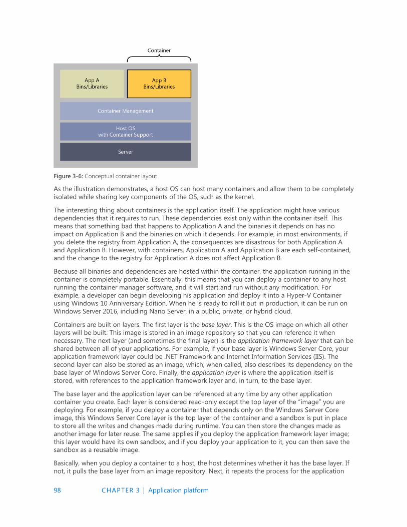
98 CHAPTER 3 | Application platform
Figure 3-6: Conceptual container layout
As the illustration demonstrates, a host OS can host many containers and allow them to be completely
isolated while sharing key components of the OS, such as the kernel.
The interesting thing about containers is the application itself. The application might have various
dependencies that it requires to run. These dependencies exist only within the container itself. This
means that something bad that happens to Application A and the binaries it depends on has no
impact on Application B and the binaries on which it depends. For example, in most environments, if
you delete the registry from Application A, the consequences are disastrous for both Application A
and Application B. However, with containers, Application A and Application B are each self-contained,
and the change to the registry for Application A does not affect Application B.
Because all binaries and dependencies are hosted within the container, the application running in the
container is completely portable. Essentially, this means that you can deploy a container to any host
running the container manager software, and it will start and run without any modification. For
example, a developer can begin developing his application and deploy it into a Hyper-V Container
using Windows 10 Anniversary Edition. When he is ready to roll it out in production, it can be run on
Windows Server 2016, including Nano Server, in a public, private, or hybrid cloud.
Containers are built on layers. The first layer is the base layer. This is the OS image on which all other
layers will be built. This image is stored in an image repository so that you can reference it when
necessary. The next layer (and sometimes the final layer) is the application framework layer that can be
shared between all of your applications. For example, if your base layer is Windows Server Core, your
application framework layer could be .NET Framework and Internet Information Services (IIS). The
second layer can also be stored as an image, which, when called, also describes its dependency on the
base layer of Windows Server Core. Finally, the application layer is where the application itself is
stored, with references to the application framework layer and, in turn, to the base layer.
The base layer and the application layer can be referenced at any time by any other application
container you create. Each layer is considered read-only except the top layer of the “image” you are
deploying. For example, if you deploy a container that depends only on the Windows Server Core
image, this Windows Server Core layer is the top layer of the container and a sandbox is put in place
to store all the writes and changes made during runtime. You can then store the changes made as
another image for later reuse. The same applies if you deploy the application framework layer image;
this layer would have its own sandbox, and if you deploy your application to it, you can then save the
sandbox as a reusable image.
Basically, when you deploy a container to a host, the host determines whether it has the base layer. If
not, it pulls the base layer from an image repository. Next, it repeats the process for the application
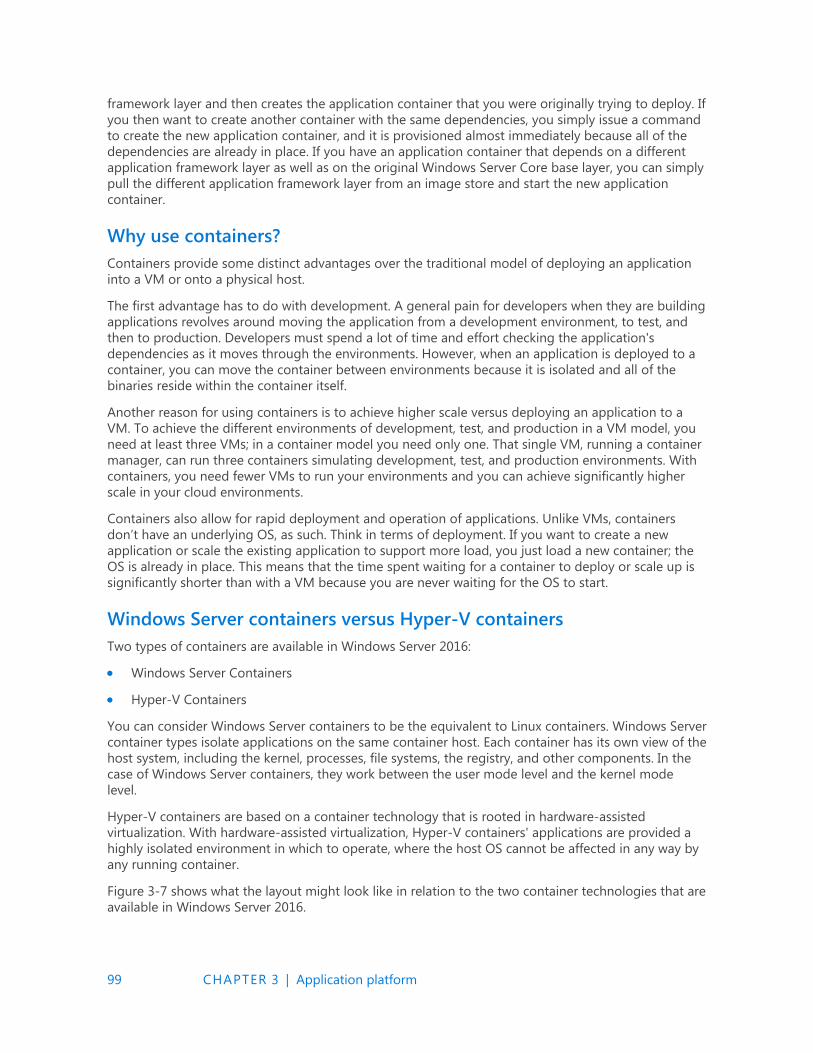
99 CHAPTER 3 | Application platform
framework layer and then creates the application container that you were originally trying to deploy. If
you then want to create another container with the same dependencies, you simply issue a command
to create the new application container, and it is provisioned almost immediately because all of the
dependencies are already in place. If you have an application container that depends on a different
application framework layer as well as on the original Windows Server Core base layer, you can simply
pull the different application framework layer from an image store and start the new application
container.
Why use containers?
Containers provide some distinct advantages over the traditional model of deploying an application
into a VM or onto a physical host.
The first advantage has to do with development. A general pain for developers when they are building
applications revolves around moving the application from a development environment, to test, and
then to production. Developers must spend a lot of time and effort checking the application's
dependencies as it moves through the environments. However, when an application is deployed to a
container, you can move the container between environments because it is isolated and all of the
binaries reside within the container itself.
Another reason for using containers is to achieve higher scale versus deploying an application to a
VM. To achieve the different environments of development, test, and production in a VM model, you
need at least three VMs; in a container model you need only one. That single VM, running a container
manager, can run three containers simulating development, test, and production environments. With
containers, you need fewer VMs to run your environments and you can achieve significantly higher
scale in your cloud environments.
Containers also allow for rapid deployment and operation of applications. Unlike VMs, containers
don’t have an underlying OS, as such. Think in terms of deployment. If you want to create a new
application or scale the existing application to support more load, you just load a new container; the
OS is already in place. This means that the time spent waiting for a container to deploy or scale up is
significantly shorter than with a VM because you are never waiting for the OS to start.
Windows Server containers versus Hyper-V containers
Two types of containers are available in Windows Server 2016:
Windows Server Containers
Hyper-V Containers
You can consider Windows Server containers to be the equivalent to Linux containers. Windows Server
container types isolate applications on the same container host. Each container has its own view of the
host system, including the kernel, processes, file systems, the registry, and other components. In the
case of Windows Server containers, they work between the user mode level and the kernel mode
level.
Hyper-V containers are based on a container technology that is rooted in hardware-assisted
virtualization. With hardware-assisted virtualization, Hyper-V containers' applications are provided a
highly isolated environment in which to operate, where the host OS cannot be affected in any way by
any running container.
Figure 3-7 shows what the layout might look like in relation to the two container technologies that are
available in Windows Server 2016.
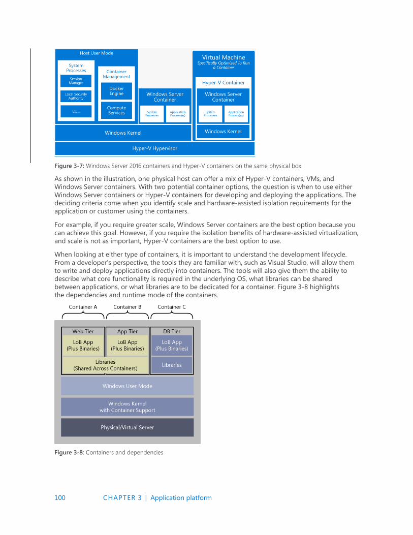
100 CHAPTER 3 | Application platform
Figure 3-7: Windows Server 2016 containers and Hyper-V containers on the same physical box
As shown in the illustration, one physical host can offer a mix of Hyper-V containers, VMs, and
Windows Server containers. With two potential container options, the question is when to use either
Windows Server containers or Hyper-V containers for developing and deploying the applications. The
deciding criteria come when you identify scale and hardware-assisted isolation requirements for the
application or customer using the containers.
For example, if you require greater scale, Windows Server containers are the best option because you
can achieve this goal. However, if you require the isolation benefits of hardware-assisted virtualization,
and scale is not as important, Hyper-V containers are the best option to use.
When looking at either type of containers, it is important to understand the development lifecycle.
From a developer’s perspective, the tools they are familiar with, such as Visual Studio, will allow them
to write and deploy applications directly into containers. The tools will also give them the ability to
describe what core functionality is required in the underlying OS, what libraries can be shared
between applications, or what libraries are to be dedicated for a container. Figure 3-8 highlights
the dependencies and runtime mode of the containers.
Figure 3-8: Containers and dependencies
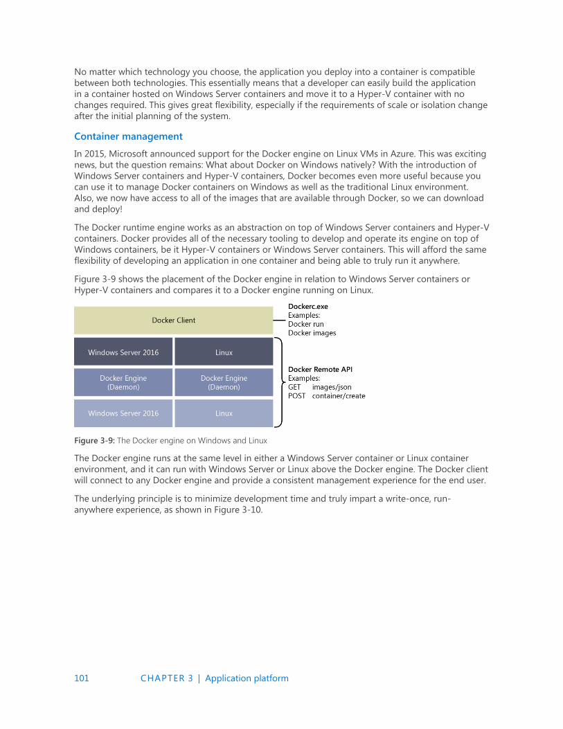
101 CHAPTER 3 | Application platform
No matter which technology you choose, the application you deploy into a container is compatible
between both technologies. This essentially means that a developer can easily build the application
in a container hosted on Windows Server containers and move it to a Hyper-V container with no
changes required. This gives great flexibility, especially if the requirements of scale or isolation change
after the initial planning of the system.
Container management
In 2015, Microsoft announced support for the Docker engine on Linux VMs in Azure. This was exciting
news, but the question remains: What about Docker on Windows natively? With the introduction of
Windows Server containers and Hyper-V containers, Docker becomes even more useful because you
can use it to manage Docker containers on Windows as well as the traditional Linux environment.
Also, we now have access to all of the images that are available through Docker, so we can download
and deploy!
The Docker runtime engine works as an abstraction on top of Windows Server containers and Hyper-V
containers. Docker provides all of the necessary tooling to develop and operate its engine on top of
Windows containers, be it Hyper-V containers or Windows Server containers. This will afford the same
flexibility of developing an application in one container and being able to truly run it anywhere.
Figure 3-9 shows the placement of the Docker engine in relation to Windows Server containers or
Hyper-V containers and compares it to a Docker engine running on Linux.
Figure 3-9: The Docker engine on Windows and Linux
The Docker engine runs at the same level in either a Windows Server container or Linux container
environment, and it can run with Windows Server or Linux above the Docker engine. The Docker client
will connect to any Docker engine and provide a consistent management experience for the end user.
The underlying principle is to minimize development time and truly impart a write-once, run-
anywhere experience, as shown in Figure 3-10.
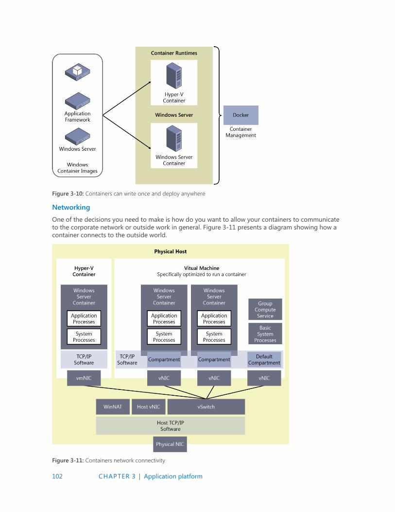
102 CHAPTER 3 | Application platform
Figure 3-10: Containers can write once and deploy anywhere
Networking
One of the decisions you need to make is how do you want to allow your containers to communicate
to the corporate network or outside work in general. Figure 3-11 presents a diagram showing how a
container connects to the outside world.
Figure 3-11: Containers network connectivity
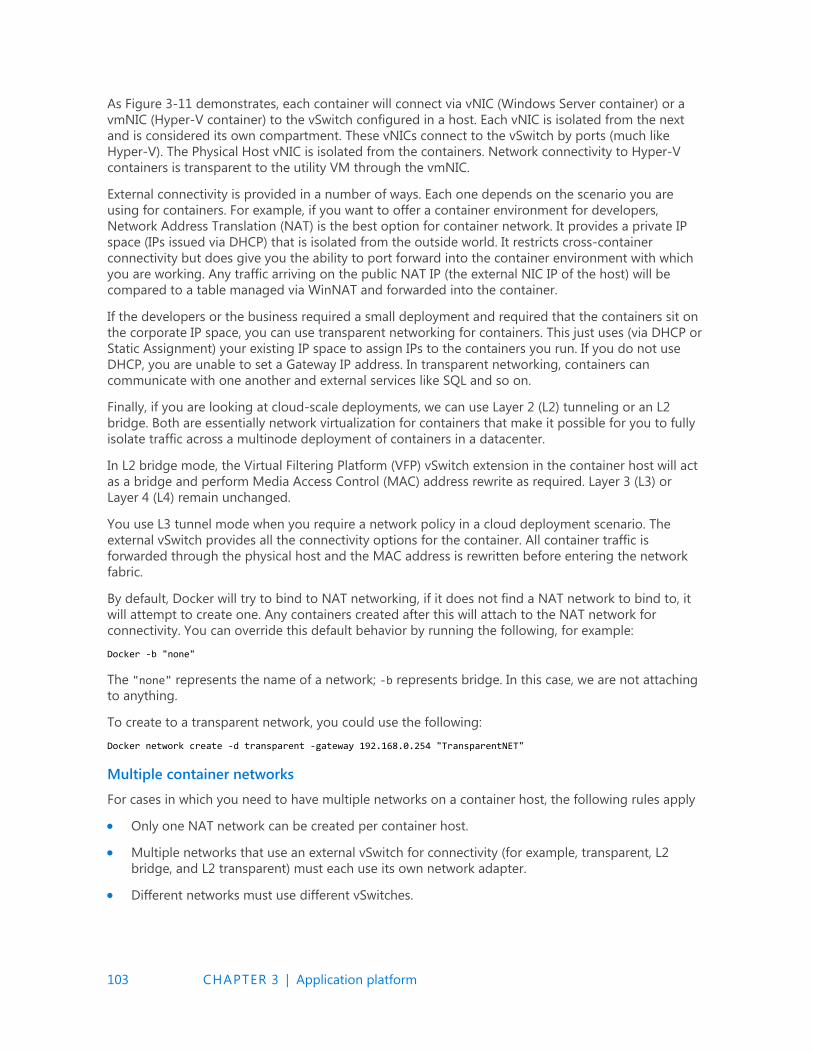
103 CHAPTER 3 | Application platform
As Figure 3-11 demonstrates, each container will connect via vNIC (Windows Server container) or a
vmNIC (Hyper-V container) to the vSwitch configured in a host. Each vNIC is isolated from the next
and is considered its own compartment. These vNICs connect to the vSwitch by ports (much like
Hyper-V). The Physical Host vNIC is isolated from the containers. Network connectivity to Hyper-V
containers is transparent to the utility VM through the vmNIC.
External connectivity is provided in a number of ways. Each one depends on the scenario you are
using for containers. For example, if you want to offer a container environment for developers,
Network Address Translation (NAT) is the best option for container network. It provides a private IP
space (IPs issued via DHCP) that is isolated from the outside world. It restricts cross-container
connectivity but does give you the ability to port forward into the container environment with which
you are working. Any traffic arriving on the public NAT IP (the external NIC IP of the host) will be
compared to a table managed via WinNAT and forwarded into the container.
If the developers or the business required a small deployment and required that the containers sit on
the corporate IP space, you can use transparent networking for containers. This just uses (via DHCP or
Static Assignment) your existing IP space to assign IPs to the containers you run. If you do not use
DHCP, you are unable to set a Gateway IP address. In transparent networking, containers can
communicate with one another and external services like SQL and so on.
Finally, if you are looking at cloud-scale deployments, we can use Layer 2 (L2) tunneling or an L2
bridge. Both are essentially network virtualization for containers that make it possible for you to fully
isolate traffic across a multinode deployment of containers in a datacenter.
In L2 bridge mode, the Virtual Filtering Platform (VFP) vSwitch extension in the container host will act
as a bridge and perform Media Access Control (MAC) address rewrite as required. Layer 3 (L3) or
Layer 4 (L4) remain unchanged.
You use L3 tunnel mode when you require a network policy in a cloud deployment scenario. The
external vSwitch provides all the connectivity options for the container. All container traffic is
forwarded through the physical host and the MAC address is rewritten before entering the network
fabric.
By default, Docker will try to bind to NAT networking, if it does not find a NAT network to bind to, it
will attempt to create one. Any containers created after this will attach to the NAT network for
connectivity. You can override this default behavior by running the following, for example:
Docker -b "none"
The "none" represents the name of a network; -b represents bridge. In this case, we are not attaching
to anything.
To create to a transparent network, you could use the following:
Docker network create -d transparent -gateway 192.168.0.254 "TransparentNET"
Multiple container networks
For cases in which you need to have multiple networks on a container host, the following rules apply
Only one NAT network can be created per container host.
Multiple networks that use an external vSwitch for connectivity (for example, transparent, L2
bridge, and L2 transparent) must each use its own network adapter.
Different networks must use different vSwitches.
104 CHAPTER 3 | Application platform
Firewalls
Every container host has a set of firewall rules turned on by default, the firewall rules are configured
with a default set. If you want containers to be pingable (ICMP) or receive an IP Address from DHCP,
you need to ensure that the container host has these rules turned on. To allow different traffic types
into the containers you also will need to configure additional rules.
If you are using NAT and decide to turn on port forwarding for the containers, the firewall rules will be
automatically created for you during configuration.
Troubleshooting
Docker no longer keeps a separate log file; it logs all events to the Application Log in Event Viewer.
You can filter based on source equal to Docker and retrieve all of its events or you can use Windows
PowerShell to review the log, as well, by using the following code:
Get-EventLog -LogName Application -Source Docker
You could also start Docker in debug mode by using this:
Dockerd.exe -D
Or, use the docker configuration file (you can locate this file [or place it if it does not exist] at
C:\ProgramData\docker\config\daemon.json) to start debug mode as follows:
{ "debug": true }
Installing containers
To use Windows Server Containers, you must first install the Containers feature. Further, if you would
like to also use Hyper-V Containers, you will have to also install the Hyper-V feature.
You will then need to install and set up Docker, which does not come with Windows Server 2016.
More info Follow the URL for details on how to set up these feature and how to install and set up Docker, go to https://aka.ms/windowscontainers and read the Quick Start guides.
Rules for containers
For Windows, the container image you download must be an OS image that matches the container
host in respect of build and patch level. Table 3-1 details the support of what base image will run on
what type of container host.
Table 3-1: Supported container images on container hosts
Container OS runtime
Server Core Nano Server (AB1)
Co
nta
iner
Ho
st O
S
Dep
loym
en
t
Server with UI (LTSB) Windows Server Containers
and/or Hyper-V Containers
Windows Server Containers
and/or Hyper-V Containers
Server Core (LTSB) Windows Server Containers
and/or Hyper-V Containers
Windows Server Containers
and/or Hyper-V Containers
Nano Server (AB1) Hyper-V Containers Windows Server Containers
or Hyper-V Container

105 CHAPTER 3 | Application platform
Patching a container host will require you to patch the container image and commit to ensure normal
operation.
Microsoft will provide an updated Windows Docker image on a monthly basis, which you can use to
rebuild your container image.
If you are planning on using Hyper-V containers inside a guest VM, you must ensure the following:
Nested Virtualization is turned on for the container host
There is at least 4 GB of RAM on the host
You’re using Windows Server 2016 or Windows 10 for the host OS
The container host guest VM needs at least two virtual processors
There are additional images in the Docker repository that also follow the same rules.
More info This book does not present a deep deployment guide for Windows Server containers. For more information, go to https://msdn.microsoft.com/virtualization/windowscontainers/ quick_start/manage_docker.

106 CHAPTER 4 | Security and identity
C H A P T E R
4
Security and identity Over the past several years, cybersecurity has been consistently rated as a
top priority for IT. This is not surprising, given that top companies and
government agencies are being publicly called out for being hacked and
failing to protect their customers’ and employees’ personal information.
On the other hand, with readily available tools and a lack of adequate protections, attackers are able
to infiltrate large organizations and remain undetected for long periods of time while conducting
exfiltration of secrets or attacking internal resources.
In this chapter, we explore the layers of protection in Microsoft Windows Server 2016 that help
address emerging threats and make it an active participant in your security defenses. First, we will
describe the new shielded virtual machine solution that protects virtual machines (VMs) from attacks
on the underlying fabric.
Then, we introduce you to the extensive threat-resistance components built in to the Windows Server
2016 operating system (OS) and the enhanced auditing events that can help security systems detect
malicious activity.
Last, we will share with you an end-to-end plan for securing privileged access based on existing and
new capabilities in Windows Server.

107 CHAPTER 4 | Security and identity
Shielded VMs
By John Saville
Today, in most virtual environments there are many types of administrators who have access to VM
assets, such as storage. That includes virtualization administrators, storage administrators, network
administrators, backup administrators, just to name just a few. Many organizations including hosting
providers need a way to secure VMs—even from administrators—which is exactly what shielded VMs
provides. Keep in mind that this protection from administrators is needed for a number of reasons.
Here are just a few:
Phishing attacks
Stolen administrator credentials
Insider attacks
Shielded VMs provide protection for the data and state of the VM against inspection, theft, and
tampering from administrator privileges. Shielded VMs work for Generation 2 VMs that provide the
necessary secure startup, UEFI firmware, and virtual Trusted Platform Module (vTPM) 2.0 support
required. Although the Microsoft Hyper-V hosts must be running Windows Server 2016, the guest OS
in the VM can be Windows Server 2012 or above.
A new Host Guardian Service instance is deployed in the environment, which stores the keys required
for an approved Hyper-V host that can prove its health to run shielded VMs.
A shielded VM provides the following benefits:
BitLocker encrypted drives (utilizing its vTPM)
A hardened VM worker process (VMWP) that encrypts live migration traffic in addition to its
runtime state file, saved state, checkpoints, and even Hyper-V Replica files
No console access in addition to blocking Windows PowerShell Direct, Guest File Copy Integration
Components, and other services that provide possible paths from a user or process with
administrative privileges to the VM
How is this security possible? First, it’s important that the Hyper-V host has not been compromised
before the required keys to access VM resources are released from the Host Guardian Service (HGS).
This attestation can happen in one of two ways. The preferred way is by using the TPM 2.0 that is
present in the Hyper-V host. Using the TPM, the boot path of the server is assured, which guarantees
no malware or root kits are on the server that could compromise the security. The TPM secures
communication to and from the HGS attestation service. For hosts that do not have a TPM 2.0, an
alternate Active Directory–based attestation is possible; however, this merely checks whether the host
is part of a configured Active Directory group. Therefore, it does not provide the same levels of
assurance and protection from binary meddling and thus host administrator privileges for a
sophisticated attacker. However, the same shielded VM features are available.
After a host undergoes the attestation, it receives a health certificate from the attestation service on
the HGS that authorizes the host to get keys released from the key protection service that also runs
on the HGS. The keys are encrypted during transmission and can be decrypted only within a protected
enclave that is new to Windows 10 and Windows Server 2016 (more on that later). These keys can
then be used to decrypt the vTPM to make it possible for the VM to access its BitLocker-protected
storage and start the VM. Therefore, only if a host is authorized and noncompromised will it be able
to get the required key and turn on the VM’s access to the encrypted storage (not the administrator,
though, as the virtual hard drive (VHD) remains encrypted on the drive).
108 CHAPTER 4 | Security and identity
At this point, it might be self-defeating: If I am an administrator on the Hyper-V and the keys are
released to the host to start the VM, I would be able to gain access to the memory of the host and
get the keys, thus nullifying the very security that should protect VMs from administrative privileges.
Fortunately, another new feature in Windows 10 and Windows Server 2016 prevents this from
happening. This feature is the protected enclave mentioned earlier, which is known as Virtual Secure
Mode (VSM). A number of components use this service, including Credential Guard. VSM is a secure
execution environment in which secrets and keys are maintained and critical security processes run as
Trustlets (small trusted processes) in a secure virtualized partition.
This is not a Hyper-V VM; rather, think of it like a small virtual safe that is protected by virtualization
based on technologies such as Second Level Address Translation (SLAT) to prevent people from trying
to directly access memory, I/O Memory Management Unit (IOMMU) to protect against Direct Memory
Access (DMA) attacks, and so on. The Windows operating system, even the kernel, has no access to
VSM. Only safe processes (Trustlets) that are Microsoft signed are allowed to cross the “bridge” to
access VSM. A vTPM Trustlet is used for the vTPM of each VM, separate from the rest of the VM
process, which runs in a new type of protected VM worker process. This means that there is no way to
access the memory used to store these keys, even with complete kernel access. If I'm running with a
debugger attached, for example, that would be flagged as part of the attestation process, the health
check would fail, and the keys would not be released to the host. Remember I mentioned the keys
from the key protection service are sent encrypted? It's the VSM that decrypts them, always keeping
the decrypted key protected from the host OS.
When you put all of this together, you have the ability to create a secure VM environment that is
protected from any level of administrator (when using TPM 2.0 in the host) and will close a security
hole many environments cannot close today.
More info To read detailed guides that Microsoft has provided to implement this scenario in your environment, go to https://gallery.technet.microsoft.com/Shielded-VMs-and-Guarded-44176db3/view/Discussions.
Threat-resistant technologies Windows Server 2016 includes integrated threat-resistance technologies that make it an active
component in your overall security story. These technologies range from blocking external attackers
trying to exploit vulnerabilities (Control Flow Guard) to resistance to attacks by malicious users and
software that gained administrator access to the server (Credential Guard and Device Guard). In this
section, we explore some of these new features.
Control Flow Guard
In Windows Server 2016 and Windows 10, the OS is protected by Control Flow Guard. This highly
optimized platform security feature makes it much more difficult to run arbitrary code through
exploits such as buffer overflows.
In addition, when a developer compiles his code, the compiler will perform some security checks on
the code and then identify the set of functions that are considered a source for an indirect call. These
indirect calls might come from a code exploit whereby malformed data is sent into the function,
causing it to behave abnormally. The indirect call in non–Control Flow Guard–aware code can cause
a memory buffer overrun, which can corrupt other applications or lead to privileged execution.
However, because the compiler has identified these sets of functions as potential vulnerabilities and
marked them, the runtime will detect and provide additional logic that verifies whether an indirect
call is actually valid. If the indirect call validation fails, the application will terminate, preventing the
application from causing further damage to the system.

109 CHAPTER 4 | Security and identity
Device Guard on Windows Server 2016
With thousands of new malicious files created every day, using traditional methods like antivirus
solutions—signature-based detection to fight against malware—might not be sufficient for some
environments. Device Guard on Windows Server 2016 changes from a mode in which apps are trusted
unless blocked by an antivirus or other security solution, to a mode in which the operating system
trusts only apps authorized by your enterprise.
What is Device Guard
Device Guard can protect software running in Kernel mode and User mode. Under Kernel mode
protection, Device Guard ensures that the drivers are at the very least signed by a known signature
(WHQL signed) or you can further restrict the drivers by placing them in a safe-programs list in the
policy. Device Guard will block drivers from loading dynamic code and block any driver that is not on
the safe-programs list. If there is a compromised driver that tries to modify code in memory, it cannot
be run on the machine. Device Guard also provides User mode protection (UMCI), meaning that you
can create Code Integrity (CI) policies that define what’s trusted and authorized to run on individual
servers.
For details on Device Guard, here are some good references (note that this is not a complete list):
Introduction to Device Guard
Requirements for deployment planning for Device Guard
Code integrity policies
Enhanced Kernel Mode protection using Hypervisor Code Integrity
The core functionality and protection of Device Guard begins at the hardware level. Devices that have
processors equipped with SLAT technologies and virtualization extensions, such as Intel VT x and AMD
V, will be able to take advantage of a Virtualization Based Security (VBS) environment that
dramatically enhances Windows security by isolating critical Windows services from the operating
system itself.
Device Guard uses VBS to isolate its Hypervisor Code Integrity (HVCI) service, which makes it possible
for Device Guard to help protect kernel mode processes and drivers from vulnerability exploits and
zero-day attacks. HVCI uses the processor’s functionality to force all software running in kernel mode
to safely allocate memory. This means that after memory has been allocated, its state must be
changed from writable to read-only or run-only. By forcing memory into these states, it helps to
ensure that attacks are unable to inject malicious code into Kernel mode processes and drivers
through techniques such as buffer overruns or heap spraying.
To deliver this level of security, Device Guard has the following hardware and software requirements:
UEFI Secure Boot (optionally with a non-Microsoft UEFI CA removed from the UEFI database)
Virtualization support turned on by default in the system firmware (BIOS):
Virtualization extensions (for example, Intel VT-x and AMD RVI)
SLAT (for example, Intel EPT and AMD RVI)
IOMMU (for example, Intel VT-d, AMD-Vi)

110 CHAPTER 4 | Security and identity
UEFI BIOS configured to prevent an unauthorized user from disabling Device Guard–dependent
hardware security features (for example, Secure Boot)
Kernel-mode drivers signed and compatible with hypervisor-enforced code integrity
You can deploy HVCI (aka Virtualization Based Security of Code Integrity) by using Group Policy. It is
recommended to enable HVCI on all the servers running Windows Server 2016. For more details of
Group Policy configuration, go to https://technet.microsoft.com/itpro/windows/keep-secure/deploy-
device-guard-enable-virtualization-based-security.
Deploy configurable code Integrity policy
Historically, most malware has been unsigned. Simply by deploying code integrity policies,
organizations can get immediate protection against unsigned malware, which is estimated to be
responsible for the vast majority of current attacks. By using code integrity policies, an enterprise can
also select exactly which binaries are allowed to run in both User mode and Kernel mode. When
completely enforced, it will load only specific applications or software with specific signatures. This
feature alone fundamentally changes security in an enterprise.
You can run configurable code integrity independent of HVCI, thus making it available to devices that
don’t meet the HVCI hardware requirements.
Configurable code integrity policy offers a wide range of options to allow administrators to define the
level of control of what software to trust on a server, ranging from allowing software signed by
reputable publishers (e.g., Microsoft) to a specific file match hash.
It is recommended that you always first deploy code integrity policies in audit mode, which makes it
possible for you to review the binaries fail to load under the policy. You can then adjust the policy
before changing the code integrity policy to enforcement mode.
In this document, we illustrate two common types of code integrity policies: one for general server
usage, and another one for locked down servers:
General server usage Servers that run a variety of workloads, expected to have new software
installed from time to time, flexible in that for which they are used.
Locked down servers Servers that run a specific workload, critical in their reliability, such as
Hyper-V host or domain controllers.
Create code Integrity policy for general server usage
To create the code integrity policy, you can begin by building a reference server on their standard
hardware, and then install all of the software that their servers are known to run. Then, run the
following cmdlet:
New-CIPolicy -Level Publisher -Fallback Hash -UserPEs -FilePath C:\CI\Publisher.xml
More info For details of the level parameter, go to https://technet.microsoft.com/en-us/itpro/windows/keep-secure/deploy-code-integrity-policies-policy-rules-and-file-rules#code-integrity-file-rule-levels.
This cmdlet creates the policy by scanning the files on the server, and extracts the publisher
information from the files and adds it to the policy. The policy is created in auditing mode. Under
audit mode, files that are not covered by the CI policy will be able to load; however, they will be
logged in the Microsoft\Windows\CodeIntegrity event log channel. Administrators can audit the logs
to detect any security attacks.

111 CHAPTER 4 | Security and identity
As part of normal operations, they will get software updates or perhaps add software from the same
software providers. Because the "Publisher" remains the same on those updates and software, there is
no need to update the code integrity policy.
You can deploy the same code integrity policy to servers in the same category and running the same
hardware.
Create code integrity policy for lockdown server
It is a similar process to create the code integrity policy on this category of servers, but with different
level of control on the software you trust. For this type of server, we recommend using FilePublisher,
to ensure only whitelisted files can be loaded on the server. To create the Code Integrity policy, run
the following cmdlet:
New-CIPolicy -Level FilePublisher -Fallback Hash -UserPEs -FilePath C:\CI\FilePublisher.xml
This cmdlet creates the policy by scanning the files on the server and creates a safe-program list of
the files by their name, version, and publisher info in the policy. Only the files are on the safe-program
list with matching name, publisher, and version equal or greater is considered as trusted. In the case
of software update, the update to the files covered by the policy will have a higher version number;
therefore, you won’t need to regenerate CI policy. If there are new files added to the server, you will
need to scan the new files, and merge it to the existing CI policy.
The cmdlet creates the policy in Audit mode, you can validate the policy in the Audit mode first,
ensuring that all the files you trust are covered by the CI policy. After you are comfortable with it, you
can run the following cmdlet to change it to enforcement mode:
Set-RuleOptions -FilePath C:\CI\FilePublisher.xml -Option 3 -delete
Deploy code integrity policy
The xml file created by the New-CIPolicy can’t be consumed by the system yet. To deploy the policy, it
needs to be converted to binary format, and copied to the CodeIntegrity folder under system32.
Run the following cmdlet to convert the xml file:
ConvertFrom-CIPolicy C:\CI\FilePublisher.xml C:\CI\FilePublisher.bin
Deploy CI policy:
Copy-Item C:\CI\FilePublisher.bin C:\Windows\System32\CodeIntegrity\SiPolicy.p7b
Reboot the server to allow code integrity service to load the policy.
More info For some basic information on how to get started with Code Integrity policies as well as further information about creating an audit policy and deploying it via Group Policy, go to https://technet.microsoft.com/library/mt463091(v=vs.85).aspx#code_integrity_policies.
Credential Guard
Credential Guard isolates secrets by using virtualization-based technologies so that only privileged
systems can access them. Credential Guard offers the following features:
Hardware security This increases the security of derived domain credentials by taking
advantage of platform security features, including Secure Boot and virtualization.
Virtualization-based security Windows services that manage derived domain credentials and
other secrets run in a protected environment that is isolated from the running OS.
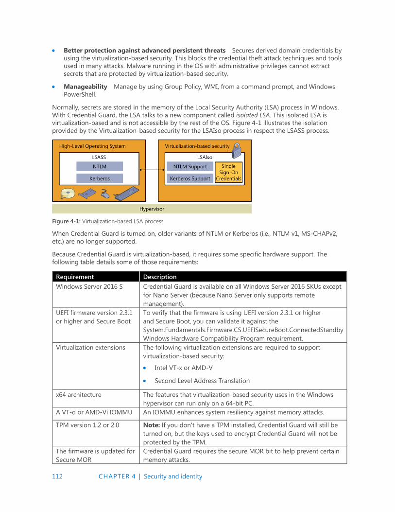
112 CHAPTER 4 | Security and identity
Better protection against advanced persistent threats Secures derived domain credentials by
using the virtualization-based security. This blocks the credential theft attack techniques and tools
used in many attacks. Malware running in the OS with administrative privileges cannot extract
secrets that are protected by virtualization-based security.
Manageability Manage by using Group Policy, WMI, from a command prompt, and Windows
PowerShell.
Normally, secrets are stored in the memory of the Local Security Authority (LSA) process in Windows.
With Credential Guard, the LSA talks to a new component called isolated LSA. This isolated LSA is
virtualization-based and is not accessible by the rest of the OS. Figure 4-1 illustrates the isolation
provided by the Virtualization-based security for the LSAIso process in respect the LSASS process.
Figure 4-1: Virtualization-based LSA process
When Credential Guard is turned on, older variants of NTLM or Kerberos (i.e., NTLM v1, MS-CHAPv2,
etc.) are no longer supported.
Because Credential Guard is virtualization-based, it requires some specific hardware support. The
following table details some of those requirements:
Requirement Description
Windows Server 2016 S Credential Guard is available on all Windows Server 2016 SKUs except
for Nano Server (because Nano Server only supports remote
management).
UEFI firmware version 2.3.1
or higher and Secure Boot
To verify that the firmware is using UEFI version 2.3.1 or higher
and Secure Boot, you can validate it against the
System.Fundamentals.Firmware.CS.UEFISecureBoot.ConnectedStandby
Windows Hardware Compatibility Program requirement.
Virtualization extensions The following virtualization extensions are required to support
virtualization-based security:
Intel VT-x or AMD-V
Second Level Address Translation
x64 architecture The features that virtualization-based security uses in the Windows
hypervisor can run only on a 64-bit PC.
A VT-d or AMD-Vi IOMMU An IOMMU enhances system resiliency against memory attacks.
TPM version 1.2 or 2.0 Note: If you don't have a TPM installed, Credential Guard will still be
turned on, but the keys used to encrypt Credential Guard will not be
protected by the TPM.
The firmware is updated for
Secure MOR
Credential Guard requires the secure MOR bit to help prevent certain
memory attacks.

113 CHAPTER 4 | Security and identity
implementation
Physical PC or VM Credential Guard is supported on both physical machines or virtual
machines. For virtual machine, the Hypervisor needs to support
nested virtualization.
The simplest way to get Credential Guard implemented for your organization is to turn it on via Group
Policy and designate the machines in your enterprise for which you want to apply it.
From the Group Policy Management Console, create a new group policy or edit an existing one. Then,
go to Computer Configuration > Administrative Templates > System > Device Guard.
Double-click Turn On Virtualization Based Security, and then, in the dialog box that opens (see Figure
4-2), select the Enabled option. In the Select Platform Security Level list box, choose Secure Boot or
Secure Boot And DMA Protection. In the Credential Guard Configuration list box, select Enabled With
UEFI lock, and then click OK. If you want to be able to turn off Credential Guard remotely, in the
Credential Guard Configuration list box, choose Enabled Without Lock instead of Enabled With
UEFI Lock.
Figure 4-2: Group policy options for Credential Guard
More info For further information, go to https://technet.microsoft.com/library/ mt483740(v=vs.85).aspx.
Remote credential guard
Remote credential guard provides protection against your credentials being stolen when you are
remotely connected to a system via a remote desktop session.
114 CHAPTER 4 | Security and identity
When a user attempts to remote desktop to a remote host, the Kerberos request is redirected back to
the originating host for authentication. The credential simply does not exist on the remote host any
more. If a remote host (i.e., an end user’s computer or server) has malicious code running on it that
can obtain credentials, remote credential guard will mitigate this because no credentials will be
passed into the remote host.
There are some requirements for remote credential guard to operate:
The user must be joined to the same Active Directory domain or a remote desktop server must be
joined to a domain with a trust relationship to the client device’s domain.
They must use Kerberos authentication.
They must be running at least Windows 10, version 1607 or Windows Server 2016.
The Remote Desktop classic Windows app is required. The Remote Desktop Universal Windows
Platform app doesn't support Remote Credential Guard.
To turn on remote credential guard, you can configure this via a group policy and widely deploy this
across your estate.
To configure this via group policy, open the Group Policy Management Console, and then go to
Computer Configuration Administrative Templates System Credentials Delegation. Next,
double-click Restrict Delegation To Remote Servers, and then select Require Remote Credential
Guard. Finally, click OK and run gpudpate /force to push the group policy out. (You also can turn on
remote credential guard via registry key—see the following “More info” link.)
More info To learn more about deploying remote credential guard, go to https://technet.microsoft.com/itpro/windows/keep-secure/remote-credential-guard.
Windows Defender
Windows Defender is included (and running) by default when you install Windows Server 2016.
If your organization has a company standard for malware technology, you can uninstall it by using
Windows PowerShell, as well:
Uninstall-WindowsFeature -Name Windows-Server-Antimalware
Windows Defender receives updates via Windows Update. If your organization manages Windows
Update via an update deployment tool, you need to ensure that you are downloading the updates to
keep Windows Defender up to date with its definitions.
You also can configure Windows Defender via Group Policy for central control and administration.
Threat detection technologies
No matter how much you try to secure an environment, you still need to perform audits to validate
whether those measures are effective. Windows Server 2016 introduces two new audit subcategories
to give you greater insight into the events:
Audit Group Membership This is part of the Logon/Logoff event category. The events in this
subcategory are generated when group memberships are enumerated or queried on the PC
where the sign-in session was created.
115 CHAPTER 4 | Security and identity
Audit PNP Activity Found in the Detailed Tracking category, you can use the Audit PNP Activity
subcategory to audit when plug-and-play detects an external device. Only Success audits are
recorded for this category.
Additional changes have been made in Windows Server 2016 that expose more information to help
you identify and address threats quickly. The following table provides more information:
Area Improvements
Kernel Default
Audit Policy
In previous releases, the kernel depended on the LSA to retrieve information
in some of its events. In Server 2016, the process creation events audit policy
is automatically turned on until an actual audit policy is received from the
LSA. This results in better auditing of services that might start before the LSA
starts
Default process
Security ACL
(SACL) to
LSASS.exe
A default process, SACL was added to LSASS.exe to log processes attempting
to access LSASS.exe. The SACL is L"S:(AU;SAFA;0x0010;;;WD)". You can turn
this on under Advanced Audit Policy Configuration|Object Access|Audit Kernel
Object.
New fields in the
sign-in event
The sign-in event ID 4624 has been updated to include more verbose
information to make them easier to analyze. The following fields have been
added to event 4624:
MachineLogon String: yes or no
If the account that signed in to the PC is a computer account, this field
will be yes; otherwise, the field is no.
ElevatedToken String: yes or no
If the account that signed in to the PC is an administrative sign-in, this
field will be yes; otherwise, the field is no. Additionally, if this is part of a
split token, the linked login ID (LSAP_LOGON_SESSION) will also be
shown.
TargetOutboundUserName String and TargetOutboundUserDomain
String
The user name and domain of the identity that was created by the
LogonUser method for outbound traffic.
VirtualAccount String: yes or no
If the account that signed in to the PC is a virtual account, this field will be
yes; otherwise, the field is no.
GroupMembership String
A list of all of the groups in the user’s token.
RestrictedAdminMode String: yes or no
If the user signs in to the PC in restricted admin mode with Remote
Desktop, this field will be yes.
116 CHAPTER 4 | Security and identity
New fields in the
process creation
event
The sign-in event ID 4688 has been updated to include more verbose
information to make it easier to analyze. The following fields have been added
to event 4688:
TargetUserSid String
The SID of the target principal.
TargetUserName String
The account name of the target user.
TargetDomainName String
The domain of the target user.
TargetLogonId String
The logon ID of the target user.
ParentProcessName String
The name of the creator process.
ParentProcessId String
A pointer to the actual parent process if it's different from the creator
process.
Security Account
Manager (SAM)
events
New SAM events were added to cover SAM APIs that perform read/query
operations. In previous versions of Windows, only write operations were
audited. The new events are event ID 4798 and event ID 4799. The following
APIs are now audited:
SamrEnumerateGroupsInDomain
SamrEnumerateUsersInDomain
SamrEnumerateAliasesInDomain
SamrGetAliasMembership
SamrLookupNamesInDomain
SamrLookupIdsInDomain
SamrQueryInformationUser
SamrQueryInformationGroup
SamrQueryInformationUserAlias
SamrGetMembersInGroup
SamrGetMembersInAlias
SamrGetUserDomainPasswordInformation
Boot
Configuration
Database (BCD)
events
Event ID 4826 has been added to track the following changes to the BCD:
DEP/NEX settings
Test signing
PCAT SB simulation
Debug
Boot debug
Integrity Services
Disable Winload debugging menu
PNP Events Event ID 6416 has been added to track when an external device is detected
through plug-and-play. One important scenario is if an external device that
contains malware is inserted into a high-value machine that doesn’t expect
this type of action, such as a domain controller.

117 CHAPTER 4 | Security and identity
Securing privileged access In this section, we are going to explore a few concepts regarding securing privileged access. First we
are going to dive into the concepts of Just-in-Time and Just Enough Administration. Then, we are
going to explain how you combine all of the tools and technologies we have discussed in this chapter
into an implementation strategy for your organization.
Just-in-Time and Just Enough Administration
Just-in-Time (JIT) administration is a fairly basic concept: the principal is that we evolve to a state in
which there are no full-time administrators, or, more specifically, we have no accounts that have full-
time administrator privileges. Rather, through a simple process, the privileges required are requested
just before they are actually needed, then approved, and then granted to the account for a specific
time period. This ensures that the task can be carried out successfully with the correct amount of
privileges for the allotted time. JIT works in conjunction with Just Enough Administration (JEA) to
secure the correct privileges. In Windows Server 2016, these technologies are combined to provide
Privileged Access Management (PAM).
More info For more information about PAM, go to https://technet.microsoft.com/library/ dn903243.aspx.
Now, let’s take a quick look at JEA. This is part of the Windows Management Framework 5.0 package
and has been supported since Windows Server 2008 R2. Using JEA, you can assign specific privileges
(just enough of them) to a user account that are needed to perform a given required function. This
means that you don’t need to assign a user to an administrator account and then remember to
remove that person later. JEA gives us the role-based access control (RBAC) that modern enterprises
require to achieve more secure environments.
To implement JEA on a system, you first need a Windows PowerShell Session Configuration file. Use
the New-PSSessionConfigurationFile cmdlet to create the .pssc file you need to control access by
running the following syntax:
New-PSSessionConfigurationFile -Path "$env:Programdata\<JEAConfigDirectory>\<filename>.pssc"
The following is a sample of the default configuration file this command generates:
@{ # Version number of the schema used "for this document SchemaVersion = '2.0.0.0' # ID used to uniquely identify this document GUID = '1da190ce-fc94-4f8b-98e0-7d70fd9154b1' # Author of this document Author = 'john' # Description of the functionality provided by these settings # Description = '' # Session type defaults to apply for this session configuration. Can be 'RestrictedRemoteServer' (recommended), 'Empty', or 'Default' SessionType = 'Default' # Directory to place session transcripts for this session configuration # TranscriptDirectory = 'C:\Transcripts\' # Whether to run this session configuration as the machine's (virtual) administrator account # RunAsVirtualAccount = $true # Groups associated with machine's (virtual) administrator account # RunAsVirtualAccountGroups = 'Remote Desktop Users', 'Remote Management Users' # Scripts to run when applied to a session # ScriptsToProcess = 'C:\ConfigData\InitScript1.ps1', 'C:\ConfigData\InitScript2.ps1' # User roles (security groups), and the role capabilities that should be applied to them when applied to a session # RoleDefinitions = @{ 'CONTOSO\SqlAdmins' = @{ RoleCapabilities = 'SqlAdministration' }; 'CONTOSO\ServerMonitors' = @{ VisibleCmdlets = 'Get-Process' } } }

118 CHAPTER 4 | Security and identity
The core areas of interest to change are the SessionType, which is set to Default. For JEA to
work, you need to configure this as RestrictedRemoteServer. Next, you need to uncomment
# RunAsVirtualAccount = $True, which ensures that the session will have “virtual” administrator
privileges. Finally, you need to modify the Roledefintions section and uncomment it to reflect your
environment.
After you generate and set up the configuration file, you need to register it by using the Register-
PSSessionConfiguration cmdlet.
Register-PSSessionConfiguration -Name <Name> -Path "$env:Programdata\<JEAConfigDirectory>\<filename>.pssc"
You can test this by connecting to the machine as you would a normal Windows PowerShell remote
session.
Enter-PSSession -ComputerName <ComputerName> -ConfigurationName <JEAConfigName> -Credential $cred
You can create another file called a Role Capability file with the extension .psrc. You can use this file to
define what commands and applications are visible to the specific roles you define. You use the New-
PSRoleCapabilityFile cmdlet to create a blank template.
This file contains sections in which you can define which modules to import and which functions and
cmdlets are exposed.
# ModulesToImport = 'MyCustomModule', @{ ModuleName = 'MyCustomModule2'; ModuleVersion = '1.0.0.0'; GUID = '4d30d5f0-cb16-4898-812d-f20a6c596bdf' } # VisibleFunctions = 'Invoke-Function1', @{ Name = 'Invoke-Function2'; Parameters = @{ Name = 'Parameter1'; ValidateSet = 'Item1', 'Item2' }, @{ Name = 'Parameter2'; ValidatePattern = 'L*' } } # VisibleCmdlets = 'Invoke-Cmdlet1', @{ Name = 'Invoke-Cmdlet2'; Parameters = @{ Name = 'Parameter1'; ValidateSet = 'Item1', 'Item2' }, @{ Name = 'Parameter2'; ValidatePattern = 'L*' } }
More info JEA is a detailed subject, and we can provide only the basics here. For further guidance and to see all of the configuration options, go to http://aka.ms/JEA.
A strategy for securing privileged access
It has to be said that no matter how secure you can make an operating system or service, it is only as
secure as the weakest password. For example, suppose that you have the most sensitive data on earth
and you encrypt it by using the most sophisticated technology, but then you use a password like
“Password01”; this utterly defeats the purpose of putting in place a battery of secure technologies.
Let’s look at another scenario. Walk around your office and count how many people have written their
passwords on notes and stuck them on their keyboards or monitors. Then, observe how many people
have pictures of their family or pets on their desk. When those people need to think of a password,
what is the likelihood that it might be something personal based on the pictures?
Now, let’s consider a final scenario: the social engineering attack. With this particular form of attack—
which is a leading cause of security breaks—the attacker calls someone, out of the blue, and pretends
to be from IT, saying he needs to verify some account information. If the attacker is good at his job,
the chances are high that the hapless victim will readily provide the information.
With those scenarios in mind, the attacker will gain access to something and potentially use that
access to perform an escalated attack. But, what if the account were a privileged one in the first place.
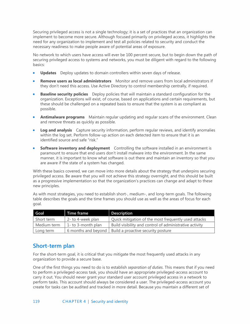
119 CHAPTER 4 | Security and identity
Securing privileged access is not a single technology; it is a set of practices that an organization can
implement to become more secure. Although focused primarily on privileged access, it highlights the
need for any organization to implement and test all policies related to security and conduct the
necessary readiness to make people aware of potential areas of exposure.
No network to which users have access will ever be 100 percent secure, but to begin down the path of
securing privileged access to systems and networks, you must be diligent with regard to the following
basics:
Updates Deploy updates to domain controllers within seven days of release.
Remove users as local administrators Monitor and remove users from local administrators if
they don’t need this access. Use Active Directory to control membership centrally, if required.
Baseline security policies Deploy policies that will maintain a standard configuration for the
organization. Exceptions will exist, of course, based on applications and certain requirements, but
these should be challenged on a repeated basis to ensure that the system is as compliant as
possible.
Antimalware programs Maintain regular updating and regular scans of the environment. Clean
and remove threats as quickly as possible.
Log and analysis Capture security information, perform regular reviews, and identify anomalies
within the log set. Perform follow-up action on each detected item to ensure that it is an
identified source and safe “risk.”
Software inventory and deployment Controlling the software installed in an environment is
paramount to ensure that end users don’t install malware into the environment. In the same
manner, it is important to know what software is out there and maintain an inventory so that you
are aware if the state of a system has changed.
With these basics covered, we can move into more details about the strategy that underpins securing
privileged access. Be aware that you will not achieve this strategy overnight, and this should be built
as a progressive implementation so that the organization’s practices can change and adapt to these
new principles.
As with most strategies, you need to establish short-, medium-, and long-term goals. The following
table describes the goals and the time frames you should use as well as the areas of focus for each
goal.
Goal Time frame Description
Short term 2- to 4-week plan Quick mitigation of the most frequently used attacks
Medium term 1- to 3-month plan Build visibility and control of administrative activity
Long term 6 months and beyond Build a proactive security posture
Short-term plan
For the short-term goal, it is critical that you mitigate the most frequently used attacks in any
organization to provide a secure base.
One of the first things you need to do is to establish separation of duties. This means that if you need
to perform a privileged-access task, you should have an appropriate privileged-access account to
carry it out. You should never grant your standard user account privileged access in a network to
perform tasks. This account should always be considered a user. The privileged-access account you
create for tasks can be audited and tracked in more detail. Because you maintain a different set of
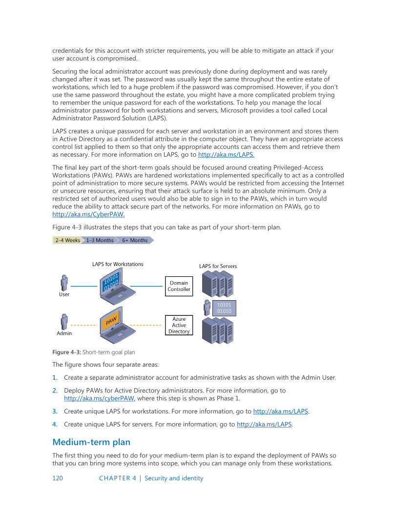
120 CHAPTER 4 | Security and identity
credentials for this account with stricter requirements, you will be able to mitigate an attack if your
user account is compromised.
Securing the local administrator account was previously done during deployment and was rarely
changed after it was set. The password was usually kept the same throughout the entire estate of
workstations, which led to a huge problem if the password was compromised. However, if you don’t
use the same password throughout the estate, you might have a more complicated problem trying
to remember the unique password for each of the workstations. To help you manage the local
administrator password for both workstations and servers, Microsoft provides a tool called Local
Administrator Password Solution (LAPS).
LAPS creates a unique password for each server and workstation in an environment and stores them
in Active Directory as a confidential attribute in the computer object. They have an appropriate access
control list applied to them so that only the appropriate accounts can access them and retrieve them
as necessary. For more information on LAPS, go to http://aka.ms/LAPS.
The final key part of the short-term goals should be focused around creating Privileged-Access
Workstations (PAWs). PAWs are hardened workstations implemented specifically to act as a controlled
point of administration to more secure systems. PAWs would be restricted from accessing the Internet
or unsecure resources, ensuring that their attack surface is held to an absolute minimum. Only a
restricted set of authorized users would also be able to sign in to the PAWs, which in turn would
reduce the ability to attack secure part of the networks. For more information on PAWs, go to
http://aka.ms/CyberPAW.
Figure 4-3 illustrates the steps that you can take as part of your short-term plan.
Figure 4-3: Short-term goal plan
The figure shows four separate areas:
1. Create a separate administrator account for administrative tasks as shown with the Admin User.
2. Deploy PAWs for Active Directory administrators. For more information, go to
http://aka.ms/cyberPAW, where this step is shown as Phase 1.
3. Create unique LAPS for workstations. For more information, go to http://aka.ms/LAPS.
4. Create unique LAPS for servers. For more information, go to http://aka.ms/LAPS.
Medium-term plan
The first thing you need to do for your medium-term plan is to expand the deployment of PAWs so
that you can bring more systems into scope, which you can manage only from these workstations.
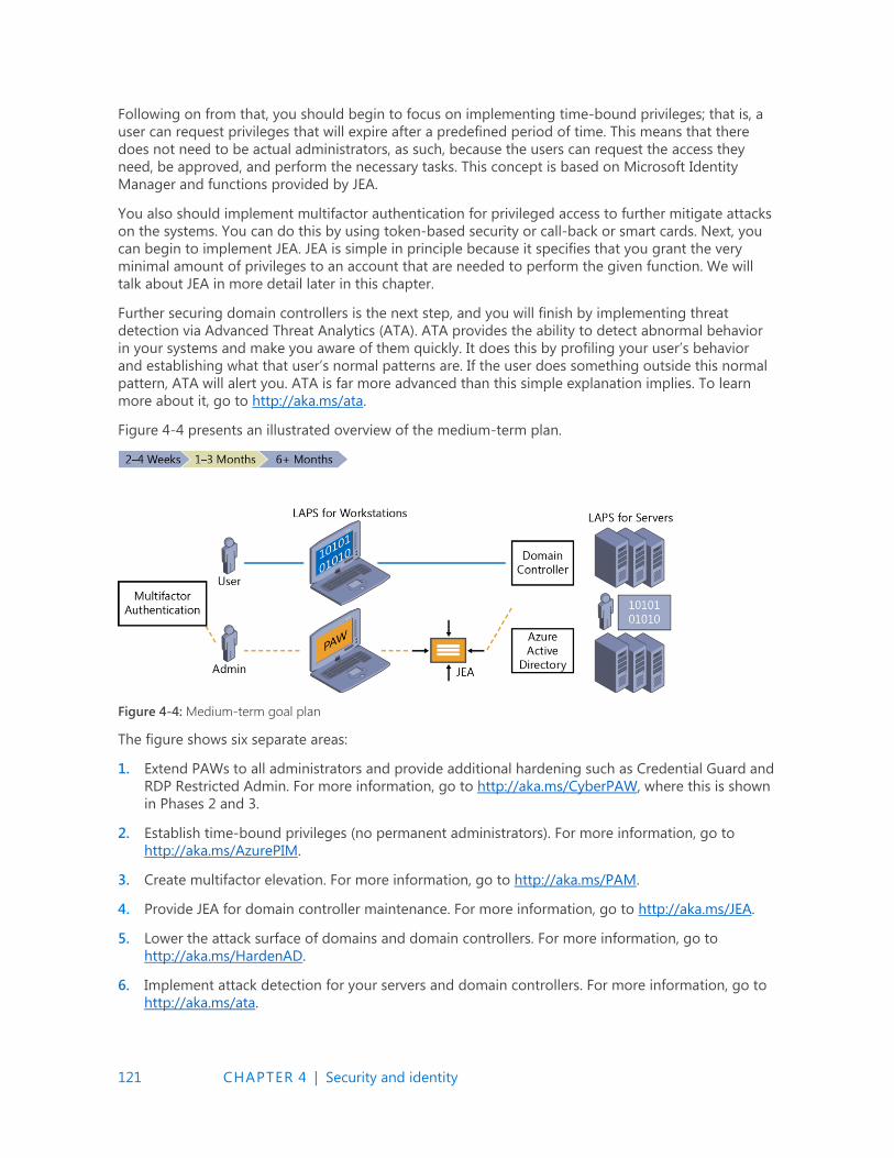
121 CHAPTER 4 | Security and identity
Following on from that, you should begin to focus on implementing time-bound privileges; that is, a
user can request privileges that will expire after a predefined period of time. This means that there
does not need to be actual administrators, as such, because the users can request the access they
need, be approved, and perform the necessary tasks. This concept is based on Microsoft Identity
Manager and functions provided by JEA.
You also should implement multifactor authentication for privileged access to further mitigate attacks
on the systems. You can do this by using token-based security or call-back or smart cards. Next, you
can begin to implement JEA. JEA is simple in principle because it specifies that you grant the very
minimal amount of privileges to an account that are needed to perform the given function. We will
talk about JEA in more detail later in this chapter.
Further securing domain controllers is the next step, and you will finish by implementing threat
detection via Advanced Threat Analytics (ATA). ATA provides the ability to detect abnormal behavior
in your systems and make you aware of them quickly. It does this by profiling your user’s behavior
and establishing what that user’s normal patterns are. If the user does something outside this normal
pattern, ATA will alert you. ATA is far more advanced than this simple explanation implies. To learn
more about it, go to http://aka.ms/ata.
Figure 4-4 presents an illustrated overview of the medium-term plan.
Figure 4-4: Medium-term goal plan
The figure shows six separate areas:
1. Extend PAWs to all administrators and provide additional hardening such as Credential Guard and
RDP Restricted Admin. For more information, go to http://aka.ms/CyberPAW, where this is shown
in Phases 2 and 3.
2. Establish time-bound privileges (no permanent administrators). For more information, go to
http://aka.ms/AzurePIM.
3. Create multifactor elevation. For more information, go to http://aka.ms/PAM.
4. Provide JEA for domain controller maintenance. For more information, go to http://aka.ms/JEA.
5. Lower the attack surface of domains and domain controllers. For more information, go to
http://aka.ms/HardenAD.
6. Implement attack detection for your servers and domain controllers. For more information, go to
http://aka.ms/ata.
122 CHAPTER 4 | Security and identity
Long-term plan
The long-term goals (see Figure 4-5) detail the final parts to date in an ever-evolving strategy.
Securing your environment never stops. Therefore, this strategy will need to be reviewed and adapted
over time, but it will provide you with a basis to begin and grow.
As with software development, you should apply a lifecycle with regard to how you control access to
resources. Your approach should be based on the latest principles and JEA. Following on from this, all
administrators should be issued strong authentication mechanisms such as SmartCard or Passport
Authentication.
To really enhance protection, you can implement a secure forest that is isolated from a traditional user
forest. Here, you can store the most secure systems in the environment and be fully isolated from the
production network. The next section is to implement code integrity, which will ensure that only
authorized code can be run on the systems.
Finally, you can use a new feature in Hyper-V Server 2016 called shielded virtual machines. This uses a
Generation 2 VM to encrypt a VM. In this case, you can begin by focusing on domain controllers so
that an attacker can’t inspect a VM and copy it from the drives or do a host attack to gain access to
the VM. Shielded VMs are described further later in this chapter.
Figure 4-5: Long-term goal plan
The figure identifies the following areas:
1. Modernize roles and the delegation model
2. Implement smart card or passport authentication for all administrators (http://aka.ms/passport)
3. Create a specific administrator forest for Active Directory administrators (http://aka.ms/ESAE)
4. Implement a code-integrity policy for domain controllers in Windows Server 2016
5. Implement shielded VMs for domain controllers in Windows Server 2016 and Hyper-V Fabric
(http://aka.ms/shieldedvms)
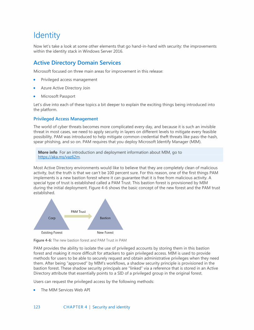
123 CHAPTER 4 | Security and identity
Identity
Now let’s take a look at some other elements that go hand-in-hand with security: the improvements
within the identity stack in Windows Server 2016.
Active Directory Domain Services
Microsoft focused on three main areas for improvement in this release:
Privileged access management
Azure Active Directory Join
Microsoft Passport
Let’s dive into each of these topics a bit deeper to explain the exciting things being introduced into
the platform.
Privileged Access Management
The world of cyber threats becomes more complicated every day, and because it is such an invisible
threat in most cases, we need to apply security in layers on different levels to mitigate every feasible
possibility. PAM was introduced to help mitigate common credential theft threats like pass-the-hash,
spear phishing, and so on. PAM requires that you deploy Microsoft Identify Manager (MIM).
More info For an introduction and deployment information about MIM, go to https://aka.ms/vaz62m.
Most Active Directory environments would like to believe that they are completely clean of malicious
activity, but the truth is that we can’t be 100 percent sure. For this reason, one of the first things PAM
implements is a new bastion forest where it can guarantee that it is free from malicious activity. A
special type of trust is established called a PAM Trust. This bastion forest is provisioned by MIM
during the initial deployment. Figure 4-6 shows the basic concept of the new forest and the PAM trust
established.
Figure 4-6: The new bastion forest and PAM Trust in PAM
PAM provides the ability to isolate the use of privileged accounts by storing them in this bastion
forest and making it more difficult for attackers to gain privileged access. MIM is used to provide
methods for users to be able to securely request and obtain administrative privileges when they need
them. After being “approved” by MIM’s workflows, a shadow security principle is provisioned in the
bastion forest. These shadow security principals are “linked” via a reference that is stored in an Active
Directory attribute that essentially points to a SID of a privileged group in the original forest.
Users can request the privileged access by the following methods:
The MIM Services Web API

124 CHAPTER 4 | Security and identity
A REST Endpoint
Windows PowerShell (using the New-PAMRequest cmdlet)
These simple methods can be integrated into other tools like automation runbooks and ticketing
systems to provide further control on the overall process.
Earlier in this chapter, we mentioned the concepts and technology of JIT and JEA, PAM is a way of
implementing this for your environment. Like JIT and JEA, PAM provides time-bound privileges to the
request account and, of course, link it to the privileged group that has the necessary permissions to
perform the task.
You also can adjust the Kerberos ticket lifetime to ensure it has the lowest possible Time-to-Live (TTL)
value. This way, if you sign in and receive a Kerberos ticket, its lifetime will be bound to the time
remaining from the total amount of time PAM has granted you access to the privileged group.
PAM also comes with a variety of new monitoring features to provide greater insight with respect to
who requested access, what type of access was actually granted, and, more important, what activities
that person performed during the privileged-access assignment.
You can view this information MIM or in the Event Viewer, or if you already have System Center
Operations Manager 2012 provisioned and use the Audit Collection Services, you can create
visualizations of the information. Other third-party tools and Operations Management Suite (OMS)
will be able to visualize the information in the future, as well.
Azure Active Directory Join
When enterprises begin to adopt the cloud and the work force becomes mobile, managing an estate
that rarely touches the corporate network can become troublesome. There are a variety of other
challenges that occur; for example, how do you give access to organizational resources on a
noncorporate device. Whatever the challenge Azure Active Directory (Azure AD) Domain Join is
another feature in Windows Server 2016 that will enhance the overall experience for identify and offer
new capabilities for both corporate and personal devices alike. Figure 4-7 demonstrates the
possibilities for Azure AD Join.
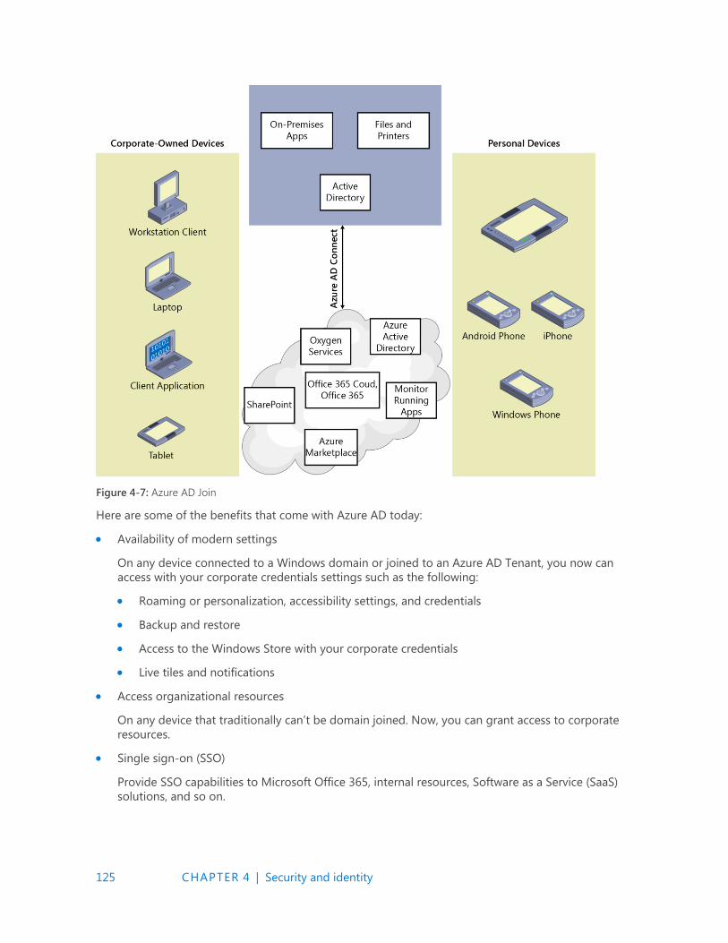
125 CHAPTER 4 | Security and identity
Figure 4-7: Azure AD Join
Here are some of the benefits that come with Azure AD today:
Availability of modern settings
On any device connected to a Windows domain or joined to an Azure AD Tenant, you now can
access with your corporate credentials settings such as the following:
Roaming or personalization, accessibility settings, and credentials
Backup and restore
Access to the Windows Store with your corporate credentials
Live tiles and notifications
Access organizational resources
On any device that traditionally can’t be domain joined. Now, you can grant access to corporate
resources.
Single sign-on (SSO)
Provide SSO capabilities to Microsoft Office 365, internal resources, Software as a Service (SaaS)
solutions, and so on.

126 CHAPTER 4 | Security and identity
Bring Your Own Device (BYOD) equipment
On personal devices where you need to access corporate resources you can now specify a work
account from which you can access those resources and be influenced by new technologies like
Conditional Access.
MDM integration
Provides the ability for the BYOD scenario to become corporate-controlled resources via an
autoenroll solution to your Mobile Device Management (MDM) solution like Microsoft Intune.
Kiosk Mode for multiple users
You can configure a device in kiosk mode so that many users can interact with a single modern
app; for example, a sign in application at the reception area of an enterprise.
Developer experience
Lets your developers build applications that can cater to business and personal uses on a single
stack
Imaging
Give further control to the end users to accept the corporate image or allow corporate policies to
be configured during the first-run experience.
Although these are all great features, why should you suddenly begin to adopt Azure AD Join?
Actually, there can be a variety of reasons, depending on what type of organization you are in. For
example, if yours is a startup organization with a large mobile foot print, providing users with the
ability to use their own laptops or personal machines that can connect to Azure AD Join would save
time and effort for the roll-out of a corporate policy. This would even stand true for more mature
organizations in relation to new markets that they want to penetrate and the difficulty they might
have in sending machines from corporate to the remote offices. Another possibility would be around
educational institutions and cloud email solutions such as those offered as a part of Office 365. These
institutions can manage all users in Azure AD and provide access to cloud email and control access to
other resources like Microsoft SharePoint Online.
Finally, it is important to highlight not only the variations between the different methods and how
users will be affected, but also what they will be able to do. Table 4-1 lists some of the key differences.

127 CHAPTER 4 | Security and identity
Table 4-1: Variations across different “join” methods
Corporate device (joined to on-
premises domain)
Corporate device (joined to the
cloud) Personal device
Users can sign in to Windows with
work credentials (as they do
today).
Users can sign in to Windows with
work credentials that are managed
in Azure AD. This is relevant for
corporate devices in three cases:
The organization doesn’t have
Active Directory on-premises
(for example, a small business).
The organization doesn’t
create all user accounts in
Active Directory (for example,
accounts for students,
consultants, or seasonal
workers are not created in
Active Directory).
The organization has corporate
devices that can’t be joined to
an (on-premises) domain, like
phones or tablets running a
Mobile SKU (for example, a
secondary device taken to a
factory/retail floor). Azure AD
Join supports joining of
corporate devices for both
managed and federated
organizations.
Users sign in to Windows
with their personal
Microsoft account
credentials (no change).
Users have access to roaming
settings and the enterprise
Windows Store. These services
work with work accounts and
don't require a personal Microsoft
account. This requires
organizations to connect their on-
premises Active Directory to
Azure AD.
Users can do self-service setup.
They can go through the first-run
experience (FRX) via their work
account as an alternative to having
IT provision the devices, although
both methods are supported.
Users can easily add a work
account that’s managed in
Active Directory or Azure
AD.
Users have SSO ability from the
desktop to work apps, websites,
and resources—including both
on-premises resources and cloud
apps that use Azure AD for
authentication.
Devices are automatically
registered in the enterprise
directory (Azure AD) and
automatically enrolled in mobile
device management. (Azure AD
Premium feature).
Users have SSO ability
across apps and to
websites/resources with
this work account.
128 CHAPTER 4 | Security and identity
Users can add their personal
Microsoft accounts to access their
personal pictures and files without
affecting enterprise data.
(Roaming settings continue to
work with their work accounts.)
The Microsoft account makes SSO
possible and no longer drives the
roaming of settings.
Users can do a self-service
password reset (SSPR) on
winlogon, meaning they can reset
a forgotten password. (Azure AD
Premium feature).
Users have access to the
enterprise Windows Store
so that they can acquire
and use line-of-business
apps on their personal
devices.
Microsoft Passport
Authentication methods are moving at a faster pace than ever before. Think about it for a moment:
you sign in to your laptop and then open your browser to go to your favorite websites where you
again sign in. In these instances, you are not always using your corporate credentials. If you hear of a
new service and want to access it, the chances are that you will be prompted to sign up and use
credentials from, for example, your public Microsoft account, Facebook, Google, and so on. The
traditional paradigm of using a dedicated identity authentication provider that you build as an
application developer is moving on and we are now using more “well-known” services like those just
mentioned.
Microsoft Passport is a new key-based authentication method that goes beyond passwords to
mitigate traditional authentication attacks. A user enrolls for Microsoft Passport but must ensure that
the authentication provider she uses supports Fast Identity Online (FIDO) authentication; thus,
through a two-step process, the user sets up Microsoft Passport on her device and sets a gesture or
PIN. This can then be used to authenticate the user via Microsoft Passport
During the setup, a certificate of asymmetric key–pair is stored on the device. The private key is stored
within the TPM chip on the device. The private key never leaves the device during the authentication
process. The public key is registered in Azure Active Directory and Windows Server Active Directory.
The user account has a mapping between the public and private key, which helps to validate the user.
Additional controls are implemented via One Time Passwords, Phonefactor, and so on.
More info For further information on deploying Microsoft Passport check the following link https://aka.ms/bh1m24.
Active Directory Federation Services
As we move forward in a cloud-focused world, being able to control your identity is becoming more
important. We need to think about how we can use our corporate identity to access applications that
we don’t technically own anymore. We also need to think about how we provide access to
applications we own to other organizations in a secure and controlled manner without having a
cumbersome user-management process.
Active Directory Federation Services (AD FS) provides this ability so that you can connect to
applications that are on-premises or in the cloud (Platform as a Service [PaaS] or SaaS) with your
corporate identity.
129 CHAPTER 4 | Security and identity
AD FS has been around for quite a while (since AD FS 2.0), and with Windows Server 2016, there are
further enhancements to the technology to ensure that it meets the next level of demands from
organizations in the cloud world. Here are some of the key improvement areas for AD FS:
Multifactor authentication
Windows Server 2016 contains a built-in Azure MFA adapter to simplify the process of using
Azure MFA as the primary provider for authentication. There is no longer a need to deploy an on-
premises MFA server.
Device registration for hybrid conditional access
You now can configure AD FS to recognize the device status. This means that you can manage the
device and apply policies as necessary. This will ensure that the device stays compliant to
corporate policy and reduce potential risks to corporate resources.
More info For further information, go to https://aka.ms/i4jy7h.
Windows 10 and Microsoft Passport integration
Microsoft Passport and AD FS have been designed to integrate to provide a further seamless
authentication experience for Windows 10 users.
Lightweight Directory Access Protocol (LDAP) integration to secure non-AD directories
Many organizations don’t rely on Active Directory for their identities. When this is the case, AD FS
will integrate into LDAP v3–compliant directories. This will allow further integration into the cloud
using those identity providers and the same enterprise experience when using Active Directory.
More info For further information, go to https://aka.ms/qqupdh.
Auditing improvements
Auditing in AD FS has been quite complicated in the past, with lots of verbose information that is
difficult to track. In Windows Server 2016, Microsoft has streamlined these improvements to prove
a more consistent auditing experience and provide easier methods to trace through the logs.
More info For further information, go to https://aka.ms/ftbvm1.
SAML 2.0 improvements
SAML support has been improved in Windows Server 2016 with the inclusion of importing trusts
based on metadata that contains multiple entities. With this support, you can configure AD FS to
participate in confederations such as InCommon Federations as well as other implementations
conforming to eGov 2.0.
More info For further information, go to https://aka.ms/d1xw4q.
Customized sign-in experience
In Windows Server 2016 you can customize messages, images, logos, and themes on a per
application basis, making it possible for multiorganizations to have one deployment rather than
multiple to suit the individual units. You can extend these customizations on a per–relying party
basis, as well.
130 CHAPTER 4 | Security and identity
More info For further information, go to https://aka.ms/f6rxu8.
Simplified password management for federated Office 365 users
AD FS can now send password expiry claims to relying party trusts. The application users will be
notified of their expiring passwords and then have the ability to take action and change their
passwords.
More info For further information, go to https://aka.ms/i8jq9x.
Configure access control policies without knowing the claim rules language
In Windows Server 2016, there are new access control policy templates which ease the
configuration of claims rules. These templates bring a simple UI-driven process to quickly and
securely create claims rules for the organization.
More info For further information, go to https://aka.ms/rf833l.
Migration from previous versions of AD FS
The upgrade process for AD FS has been greatly simplified in Windows Server 2016. Now, all
you need to do is install a Windows Server 2016 AD FS instance into an existing farm, verify the
functionality, and then remove the previous versions. AD FS in Windows Server 2016 can “act” like
a previous version of AD FS.
More info For further information, go to https://aka.ms/qo74pk.
Tell us what you think!
Is this book useful?Did it meet your expectations?Is there room for improvement?
Let us know at http://aka.ms/tellpress
Your feedback goes directly to the staff at Microsoft Press, and we read every one of your responses. Thanks in advance!
131 CHAPTER 5 | Systems management
C H A P T E R
5
Systems management By John McCabe and Ritesh Modi
This chapter explores some of the new elements for Windows Server 2016
related to systems management. We begin the discussion with Windows
PowerShell V5/V5.1 and then we will dive into detailing what’s new in
System Center 2016 and how you can take advantage of Microsoft
Operations Management Suite to have a complete hybrid management
experience. Finally, we will look at the new server management tools for
managing Windows servers from a web GUI or command-line tools.
Windows PowerShell improvements Windows PowerShell is the de facto standard for managing Microsoft technologies. With increased
support across our private and public cloud offerings, you will not find a single management solution
that provides the vast capabilities that Windows PowerShell offers today. It has become so popular, in
fact, that many third-party vendors are including Windows PowerShell support directly with their
application portfolio. Windows PowerShell now has been open-sourced, which means the community
can get involved and contribute to it and make it even better than before. Another fantastic area that
Microsoft announced in 2016 is support for Linux. Now, you can use the same interfaces and coding
standards you have developed in Windows PowerShell to manage your Linux environments. The
future is bright for Windows PowerShell and these improvements reflect the investment Microsoft is
making to ensure that it is not just the primary choice for managing Windows Environments, but
Linux, as well.
Windows PowerShell is part of the Windows Management Framework. Version 5.1 will be released
with Windows Server 2016 but is backward compatible with Windows 7 up to 2012 R2.
We cover some of the newer features throughout this chapter for 5 and 5.1 to ensure we give
coverage of the most interesting topics. However, a useful link in all Windows PowerShell user’s

132 CHAPTER 5 | Systems management
arsenal should be http://microsoft.com/PowerShell. This one stop resource gives you access to the
following:
Windows PowerShell Gallery
http://www.powershellgallery.com/
Windows PowerShell Blog
https://blogs.msdn.microsoft.com/powershell
Windows PowerShell Repo on GitHub
https://github.com/PowerShell/PowerShell
In addition, you can do the following:
Download Windows Management Framework
https://www.microsoft.com/en-us/download/details.aspx?id=50395
Review the Windows PowerShell Documentation
https://msdn.microsoft.com/en-us/powershell/scripting/powershell-scripting
Give feedback to the Windows PowerShell team
https://windowsserver.uservoice.com/forums/301869-powershell
And much more…
Here are just some of the new (or improved) features for Windows PowerShell that we discuss:
Package management
Windows PowerShell Classes
Windows PowerShell script debugging
Desired State Configuration
For a full walkthrough on what is available in WMF 5.0 and WMF 5.1, check the following links:
WMF 5.0 https://msdn.microsoft.com/powershell/wmf/5.0/releasenotes
WMF 5.1 https://msdn.microsoft.com/powershell/wmf/5.1/release-notes
Package management
If you think of how you would traditionally install software on Windows today, there are a variety of
ways. For example, you could get an .exe file or a .msi file to perform the installation. These files might
have dependencies that come in different packages or are dependent on patches with .msu
extensions. In short, installing software can be difficult. In Linux, this problem has been solved through
package management using managers like APT-GET, YUM, and so on. These managers understand
the software you are trying to install, retrieve all its dependencies, and then install the software.
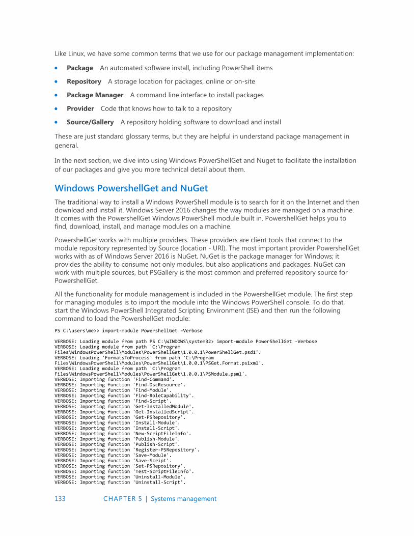
133 CHAPTER 5 | Systems management
Like Linux, we have some common terms that we use for our package management implementation:
Package An automated software install, including PowerShell items
Repository A storage location for packages, online or on-site
Package Manager A command line interface to install packages
Provider Code that knows how to talk to a repository
Source/Gallery A repository holding software to download and install
These are just standard glossary terms, but they are helpful in understand package management in
general.
In the next section, we dive into using Windows PowerShellGet and Nuget to facilitate the installation
of our packages and give you more technical detail about them.
Windows PowershellGet and NuGet
The traditional way to install a Windows PowerShell module is to search for it on the Internet and then
download and install it. Windows Server 2016 changes the way modules are managed on a machine.
It comes with the PowershellGet Windows PowerShell module built in. PowershellGet helps you to
find, download, install, and manage modules on a machine.
PowershellGet works with multiple providers. These providers are client tools that connect to the
module repository represented by Source (location - URI). The most important provider PowershellGet
works with as of Windows Server 2016 is NuGet. NuGet is the package manager for Windows; it
provides the ability to consume not only modules, but also applications and packages. NuGet can
work with multiple sources, but PSGallery is the most common and preferred repository source for
PowershellGet.
All the functionality for module management is included in the PowershellGet module. The first step
for managing modules is to import the module into the Windows PowerShell console. To do that,
start the Windows PowerShell Integrated Scripting Environment (ISE) and then run the following
command to load the PowershellGet module:
PS C:\users\me>> import-module PowershellGet –Verbose VERBOSE: Loading module from path PS C:\WINDOWS\system32> import-module PowerShellGet -Verbose VERBOSE: Loading module from path 'C:\Program Files\WindowsPowerShell\Modules\PowerShellGet\1.0.0.1\PowerShellGet.psd1'. VERBOSE: Loading 'FormatsToProcess' from path 'C:\Program Files\WindowsPowerShell\Modules\PowerShellGet\1.0.0.1\PSGet.Format.ps1xml'. VERBOSE: Loading module from path 'C:\Program Files\WindowsPowerShell\Modules\PowerShellGet\1.0.0.1\PSModule.psm1'. VERBOSE: Importing function 'Find-Command'. VERBOSE: Importing function 'Find-DscResource'. VERBOSE: Importing function 'Find-Module'. VERBOSE: Importing function 'Find-RoleCapability'. VERBOSE: Importing function 'Find-Script'. VERBOSE: Importing function 'Get-InstalledModule'. VERBOSE: Importing function 'Get-InstalledScript'. VERBOSE: Importing function 'Get-PSRepository'. VERBOSE: Importing function 'Install-Module'. VERBOSE: Importing function 'Install-Script'. VERBOSE: Importing function 'New-ScriptFileInfo'. VERBOSE: Importing function 'Publish-Module'. VERBOSE: Importing function 'Publish-Script'. VERBOSE: Importing function 'Register-PSRepository'. VERBOSE: Importing function 'Save-Module'. VERBOSE: Importing function 'Save-Script'. VERBOSE: Importing function 'Set-PSRepository'. VERBOSE: Importing function 'Test-ScriptFileInfo'. VERBOSE: Importing function 'Uninstall-Module'. VERBOSE: Importing function 'Uninstall-Script'.
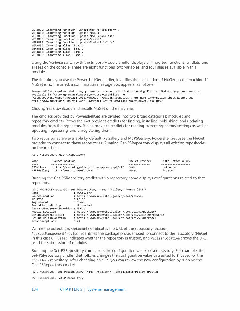
134 CHAPTER 5 | Systems management
VERBOSE: Importing function 'Unregister-PSRepository'. VERBOSE: Importing function 'Update-Module'. VERBOSE: Importing function 'Update-ModuleManifest'. VERBOSE: Importing function 'Update-Script'. VERBOSE: Importing function 'Update-ScriptFileInfo'. VERBOSE: Importing alias 'fimo'. VERBOSE: Importing alias 'inmo'. VERBOSE: Importing alias 'pumo'. VERBOSE: Importing alias 'upmo'.
Using the Verbose switch with the Import-Module cmdlet displays all imported functions, cmdlets, and
aliases on the console. There are eight functions, two variables, and four aliases available in this
module.
The first time you use the PowershellGet cmdlet, it verifies the installation of NuGet on the machine. If
NuGet is not installed, a confirmation message box appears, as follows:
PowershellGet requires NuGet_anycpu.exe to interact with NuGet-based galleries. NuGet_anycpu.exe must be available in 'C:\ProgramData\OneGet\ProviderAssemblies' or 'C:\Users\<username>\AppData\Local\OneGet\ProviderAssemblies'. For more information about NuGet, see http://www.nuget.org. Do you want PowershellGet to download NuGet_anycpu.exe now?
Clicking Yes downloads and installs NuGet on the machine.
The cmdlets provided by PowershellGet are divided into two broad categories: modules and
repository cmdlets. PowershellGet provides cmdlets for finding, installing, publishing, and updating
modules from the repository. It also provides cmdlets for reading current repository settings as well as
updating, registering, and unregistering them.
Two repositories are available by default: PSGallery and MSPSGallery. PowershellGet uses the NuGet
provider to connect to these repositories. Running Get-PSRepository displays all existing repositories
on the machine.
PS C:\users\me>> Get-PSRepository Name SourceLocation OneGetProvider InstallationPolicy ---- -------------- -------------- ------------------ PSGallery https://msconfiggallery.cloudapp.net/api/v2/ NuGet Untrusted MSPSGallery http://www.microsoft.com/ NuGet Trusted
Running the Get-PSRepository cmdlet with a repository name displays configurations related to that
repository.
PS C:\WINDOWS\system32> get-PSRepository -name PSGallery |Format-list * Name : PSGallery SourceLocation : https://www.powershellgallery.com/api/v2/ Trusted : False Registered : True InstallationPolicy : Untrusted PackageManagementProvider : NuGet PublishLocation : https://www.powershellgallery.com/api/v2/package/ ScriptSourceLocation : https://www.powershellgallery.com/api/v2/items/psscrip ScriptPublishLocation : https://www.powershellgallery.com/api/v2/package/ ProviderOptions : {}
Within the output, SourceLocation indicates the URL of the repository location,
PackageManagementProvider identifies the package provider used to connect to the repository (NuGet
in this case), Trusted indicates whether the repository is trusted, and PublishLocation shows the URL
used for submission of modules.
Running the Set-PSRepository cmdlet sets the configuration values of a repository. For example, the
Set-PSRepository cmdlet that follows changes the configuration value Untrusted to Trusted for the
PSGallery repository. After changing a value, you can review the new configuration by running the
Get-PSRepository cmdlet.
PS C:\Users\me> Set-PSRepository -Name "PSGallery" -InstallationPolicy Trusted PS C:\Users\me> Get-PSRepository
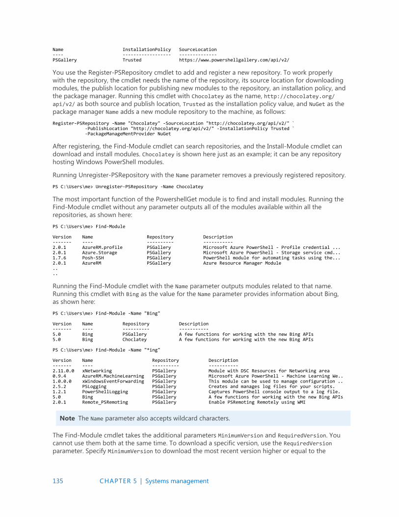
135 CHAPTER 5 | Systems management
Name InstallationPolicy SourceLocation ---- ------------------ -------------- PSGallery Trusted https://www.powershellgallery.com/api/v2/
You use the Register-PSRepository cmdlet to add and register a new repository. To work properly
with the repository, the cmdlet needs the name of the repository, its source location for downloading
modules, the publish location for publishing new modules to the repository, an installation policy, and
the package manager. Running this cmdlet with Chocolatey as the name, http://chocolatey.org/
api/v2/ as both source and publish location, Trusted as the installation policy value, and NuGet as the
package manager Name adds a new module repository to the machine, as follows:
Register-PSRepository -Name "Chocolatey" -SourceLocation "http://chocolatey.org/api/v2/" ` -PublishLocation "http://chocolatey.org/api/v2/" -InstallationPolicy Trusted ` -PackageManageMentProvider NuGet
After registering, the Find-Module cmdlet can search repositories, and the Install-Module cmdlet can
download and install modules. Chocolatey is shown here just as an example; it can be any repository
hosting Windows PowerShell modules.
Running Unregister-PSRepository with the Name parameter removes a previously registered repository.
PS C:\Users\me> Unregister-PSRepository -Name Chocolatey
The most important function of the PowershellGet module is to find and install modules. Running the
Find-Module cmdlet without any parameter outputs all of the modules available within all the
repositories, as shown here:
PS C:\Users\me> Find-Module Version Name Repository Description ------- ---- ---------- ----------- 2.0.1 AzureRM.profile PSGallery Microsoft Azure PowerShell - Profile credential ... 2.0.1 Azure.Storage PSGallery Microsoft Azure PowerShell - Storage service cmd... 1.7.6 Posh-SSH PSGallery PowerShell module for automating tasks using the... 2.0.1 AzureRM PSGallery Azure Resource Manager Module .. ..
Running the Find-Module cmdlet with the Name parameter outputs modules related to that name.
Running this cmdlet with Bing as the value for the Name parameter provides information about Bing,
as shown here:
PS C:\Users\me> Find-Module -Name "Bing" Version Name Repository Description ------- ---- ---------- ----------- 5.0 Bing PSGallery A few functions for working with the new Bing APIs 5.0 Bing Choclatey A few functions for working with the new Bing APIs PS C:\Users\me> Find-Module -Name "*ing" Version Name Repository Description ------- ---- ---------- ----------- 2.11.0.0 xNetworking PSGallery Module with DSC Resources for Networking area 0.9.4 AzureRM.MachineLearning PSGallery Microsoft Azure PowerShell - Machine Learning We.. 1.0.0.0 xWindowsEventForwarding PSGallery This module can be used to manage configuration .. 2.5.2 PSLogging PSGallery Creates and manages log files for your scripts. 1.2.1 PowerShellLogging PSGallery Captures PowerShell console output to a log file. 5.0 Bing PSGallery A few functions for working with the new Bing APIs 2.0.1 Remote_PSRemoting PSGallery Enable PSRemoting Remotely using WMI
Note The Name parameter also accepts wildcard characters.
The Find-Module cmdlet takes the additional parameters MinimumVersion and RequiredVersion. You
cannot use them both at the same time. To download a specific version, use the RequiredVersion
parameter. Specify MinimumVersion to download the most recent version higher or equal to the
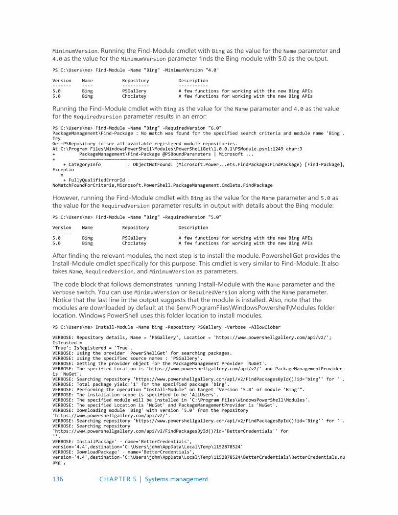
136 CHAPTER 5 | Systems management
MinimumVersion. Running the Find-Module cmdlet with Bing as the value for the Name parameter and
4.0 as the value for the MinimumVersion parameter finds the Bing module with 5.0 as the output.
PS C:\Users\me> Find-Module -Name "Bing" -MinimumVersion "4.0" Version Name Repository Description ------- ---- ---------- ----------- 5.0 Bing PSGallery A few functions for working with the new Bing APIs 5.0 Bing Choclatey A few functions for working with the new Bing APIs
Running the Find-Module cmdlet with Bing as the value for the Name parameter and 4.0 as the value
for the RequiredVersion parameter results in an error:
PS C:\Users\me> Find-Module -Name "Bing" -RequiredVersion "6.0" PackageManagement\Find-Package : No match was found for the specified search criteria and module name 'Bing'. Try Get-PSRepository to see all available registered module repositories. At C:\Program Files\WindowsPowerShell\Modules\PowerShellGet\1.0.0.1\PSModule.psm1:1249 char:3 + PackageManagement\Find-Package @PSBoundParameters | Microsoft ... + ~~~~~~~~~~~~~~~~~~~~~~~~~~~~~~~~~~~~~~~~~~~~~~~~~ + CategoryInfo : ObjectNotFound: (Microsoft.Power...ets.FindPackage:FindPackage) [Find-Package], Exceptio n + FullyQualifiedErrorId : NoMatchFoundForCriteria,Microsoft.PowerShell.PackageManagement.Cmdlets.FindPackage
However, running the Find-Module cmdlet with Bing as the value for the Name parameter and 5.0 as
the value for the RequiredVersion parameter results in output with details about the Bing module:
PS C:\Users\me> Find-Module -Name "Bing" -RequiredVersion "5.0" Version Name Repository Description ------- ---- ---------- ----------- 5.0 Bing PSGallery A few functions for working with the new Bing APIs 5.0 Bing Choclatey A few functions for working with the new Bing APIs
After finding the relevant modules, the next step is to install the module. PowershellGet provides the
Install-Module cmdlet specifically for this purpose. This cmdlet is very similar to Find-Module. It also
takes Name, RequiredVersion, and MinimumVersion as parameters.
The code block that follows demonstrates running Install-Module with the Name parameter and the
Verbose switch. You can use MinimumVersion or RequiredVersion along with the Name parameter.
Notice that the last line in the output suggests that the module is installed. Also, note that the
modules are downloaded by default at the $env:ProgramFiles\WindowsPowershell\Modules folder
location. Windows PowerShell uses this folder location to install modules.
PS C:\Users\me> Install-Module -Name bing -Repository PSGallery -Verbose -AllowClober VERBOSE: Repository details, Name = 'PSGallery', Location = 'https://www.powershellgallery.com/api/v2/'; IsTrusted = 'True'; IsRegistered = 'True'. VERBOSE: Using the provider 'PowerShellGet' for searching packages. VERBOSE: Using the specified source names : 'PSGallery'. VERBOSE: Getting the provider object for the PackageManagement Provider 'NuGet'. VERBOSE: The specified Location is 'https://www.powershellgallery.com/api/v2/' and PackageManagementProvider is 'NuGet'. VERBOSE: Searching repository 'https://www.powershellgallery.com/api/v2/FindPackagesById()?id='bing'' for ''. VERBOSE: Total package yield:'1' for the specified package 'bing'. VERBOSE: Performing the operation "Install-Module" on target "Version '5.0' of module 'Bing'". VERBOSE: The installation scope is specified to be 'AllUsers'. VERBOSE: The specified module will be installed in 'C:\Program Files\WindowsPowerShell\Modules'. VERBOSE: The specified Location is 'NuGet' and PackageManagementProvider is 'NuGet'. VERBOSE: Downloading module 'Bing' with version '5.0' from the repository 'https://www.powershellgallery.com/api/v2/'. VERBOSE: Searching repository 'https://www.powershellgallery.com/api/v2/FindPackagesById()?id='Bing'' for ''. VERBOSE: Searching repository 'https://www.powershellgallery.com/api/v2/FindPackagesById()?id='BetterCredentials'' for ''. VERBOSE: InstallPackage' - name='BetterCredentials', version='4.4',destination='C:\Users\johm\AppData\Local\Temp\1152878524' VERBOSE: DownloadPackage' - name='BetterCredentials', version='4.4',destination='C:\Users\johm\AppData\Local\Temp\1152878524\BetterCredentials\BetterCredentials.nupkg',
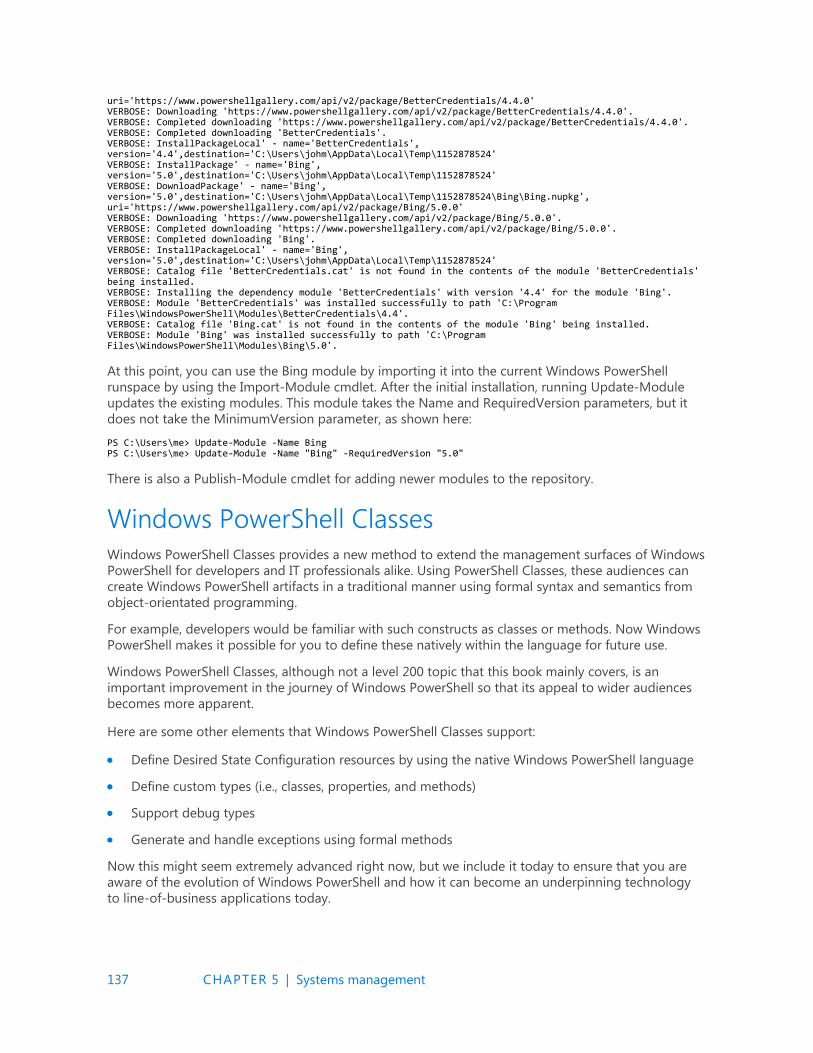
137 CHAPTER 5 | Systems management
uri='https://www.powershellgallery.com/api/v2/package/BetterCredentials/4.4.0' VERBOSE: Downloading 'https://www.powershellgallery.com/api/v2/package/BetterCredentials/4.4.0'. VERBOSE: Completed downloading 'https://www.powershellgallery.com/api/v2/package/BetterCredentials/4.4.0'. VERBOSE: Completed downloading 'BetterCredentials'. VERBOSE: InstallPackageLocal' - name='BetterCredentials', version='4.4',destination='C:\Users\johm\AppData\Local\Temp\1152878524' VERBOSE: InstallPackage' - name='Bing', version='5.0',destination='C:\Users\johm\AppData\Local\Temp\1152878524' VERBOSE: DownloadPackage' - name='Bing', version='5.0',destination='C:\Users\johm\AppData\Local\Temp\1152878524\Bing\Bing.nupkg', uri='https://www.powershellgallery.com/api/v2/package/Bing/5.0.0' VERBOSE: Downloading 'https://www.powershellgallery.com/api/v2/package/Bing/5.0.0'. VERBOSE: Completed downloading 'https://www.powershellgallery.com/api/v2/package/Bing/5.0.0'. VERBOSE: Completed downloading 'Bing'. VERBOSE: InstallPackageLocal' - name='Bing', version='5.0',destination='C:\Users\johm\AppData\Local\Temp\1152878524' VERBOSE: Catalog file 'BetterCredentials.cat' is not found in the contents of the module 'BetterCredentials' being installed. VERBOSE: Installing the dependency module 'BetterCredentials' with version '4.4' for the module 'Bing'. VERBOSE: Module 'BetterCredentials' was installed successfully to path 'C:\Program Files\WindowsPowerShell\Modules\BetterCredentials\4.4'. VERBOSE: Catalog file 'Bing.cat' is not found in the contents of the module 'Bing' being installed. VERBOSE: Module 'Bing' was installed successfully to path 'C:\Program Files\WindowsPowerShell\Modules\Bing\5.0'.
At this point, you can use the Bing module by importing it into the current Windows PowerShell
runspace by using the Import-Module cmdlet. After the initial installation, running Update-Module
updates the existing modules. This module takes the Name and RequiredVersion parameters, but it
does not take the MinimumVersion parameter, as shown here:
PS C:\Users\me> Update-Module -Name Bing PS C:\Users\me> Update-Module -Name "Bing" -RequiredVersion "5.0"
There is also a Publish-Module cmdlet for adding newer modules to the repository.
Windows PowerShell Classes
Windows PowerShell Classes provides a new method to extend the management surfaces of Windows
PowerShell for developers and IT professionals alike. Using PowerShell Classes, these audiences can
create Windows PowerShell artifacts in a traditional manner using formal syntax and semantics from
object-orientated programming.
For example, developers would be familiar with such constructs as classes or methods. Now Windows
PowerShell makes it possible for you to define these natively within the language for future use.
Windows PowerShell Classes, although not a level 200 topic that this book mainly covers, is an
important improvement in the journey of Windows PowerShell so that its appeal to wider audiences
becomes more apparent.
Here are some other elements that Windows PowerShell Classes support:
Define Desired State Configuration resources by using the native Windows PowerShell language
Define custom types (i.e., classes, properties, and methods)
Support debug types
Generate and handle exceptions using formal methods
Now this might seem extremely advanced right now, but we include it today to ensure that you are
aware of the evolution of Windows PowerShell and how it can become an underpinning technology
to line-of-business applications today.
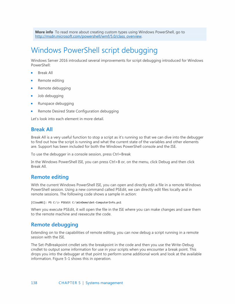
138 CHAPTER 5 | Systems management
More info To read more about creating custom types using Windows PowerShell, go to http://msdn.microsoft.com/powershell/wmf/5.0/class_overview.
Windows PowerShell script debugging
Windows Server 2016 introduced several improvements for script debugging introduced for Windows
PowerShell:
Break All
Remote editing
Remote debugging
Job debugging
Runspace debugging
Remote Desired State Configuration debugging
Let’s look into each element in more detail.
Break All
Break All is a very useful function to stop a script as it’s running so that we can dive into the debugger
to find out how the script is running and what the current state of the variables and other elements
are. Support has been included for both the Windows PowerShell console and the ISE.
To use the debugger in a console session, press Ctrl+Break
In the Windows PowerShell ISE, you can press Ctrl+B or, on the menu, click Debug and then click
Break All.
Remote editing
With the current Windows PowerShell ISE, you can open and directly edit a file in a remote Windows
PowerShell session. Using a new command called PSEdit, we can directly edit files locally and in
remote sessions. The following code shows a sample in action:
[Cloud01]: PS C:\> PSEdit C:\WinDemo\Get-ComputerInfo.ps1
When you execute PSEdit, it will open the file in the ISE where you can make changes and save them
to the remote machine and reexecute the code.
Remote debugging
Extending on to the capabilities of remote editing, you can now debug a script running in a remote
session with the ISE.
The Set-PsBreakpoint cmdlet sets the breakpoint in the code and then you use the Write-Debug
cmdlet to output some information for use in your scripts when you encounter a break point. This
drops you into the debugger at that point to perform some additional work and look at the available
information. Figure 5-1 shows this in operation.
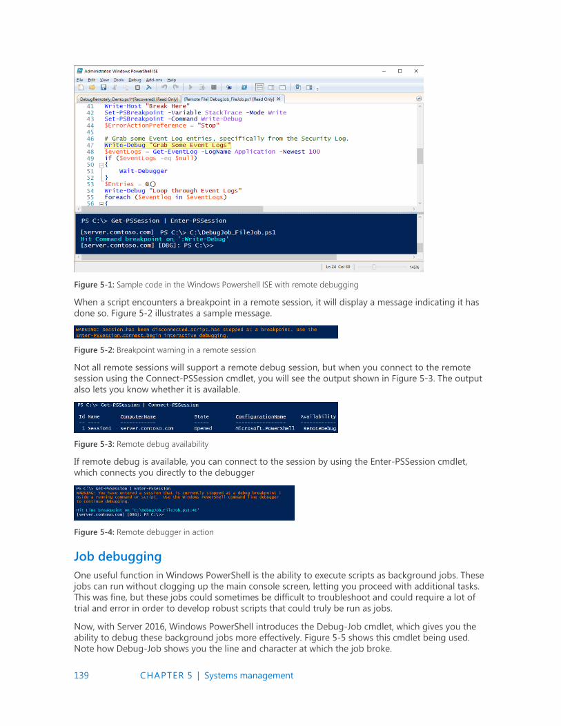
139 CHAPTER 5 | Systems management
Figure 5-1: Sample code in the Windows Powershell ISE with remote debugging
When a script encounters a breakpoint in a remote session, it will display a message indicating it has
done so. Figure 5-2 illustrates a sample message.
Figure 5-2: Breakpoint warning in a remote session
Not all remote sessions will support a remote debug session, but when you connect to the remote
session using the Connect-PSSession cmdlet, you will see the output shown in Figure 5-3. The output
also lets you know whether it is available.
Figure 5-3: Remote debug availability
If remote debug is available, you can connect to the session by using the Enter-PSSession cmdlet,
which connects you directly to the debugger
Figure 5-4: Remote debugger in action
Job debugging
One useful function in Windows PowerShell is the ability to execute scripts as background jobs. These
jobs can run without clogging up the main console screen, letting you proceed with additional tasks.
This was fine, but these jobs could sometimes be difficult to troubleshoot and could require a lot of
trial and error in order to develop robust scripts that could truly be run as jobs.
Now, with Server 2016, Windows PowerShell introduces the Debug-Job cmdlet, which gives you the
ability to debug these background jobs more effectively. Figure 5-5 shows this cmdlet being used.
Note how Debug-Job shows you the line and character at which the job broke.
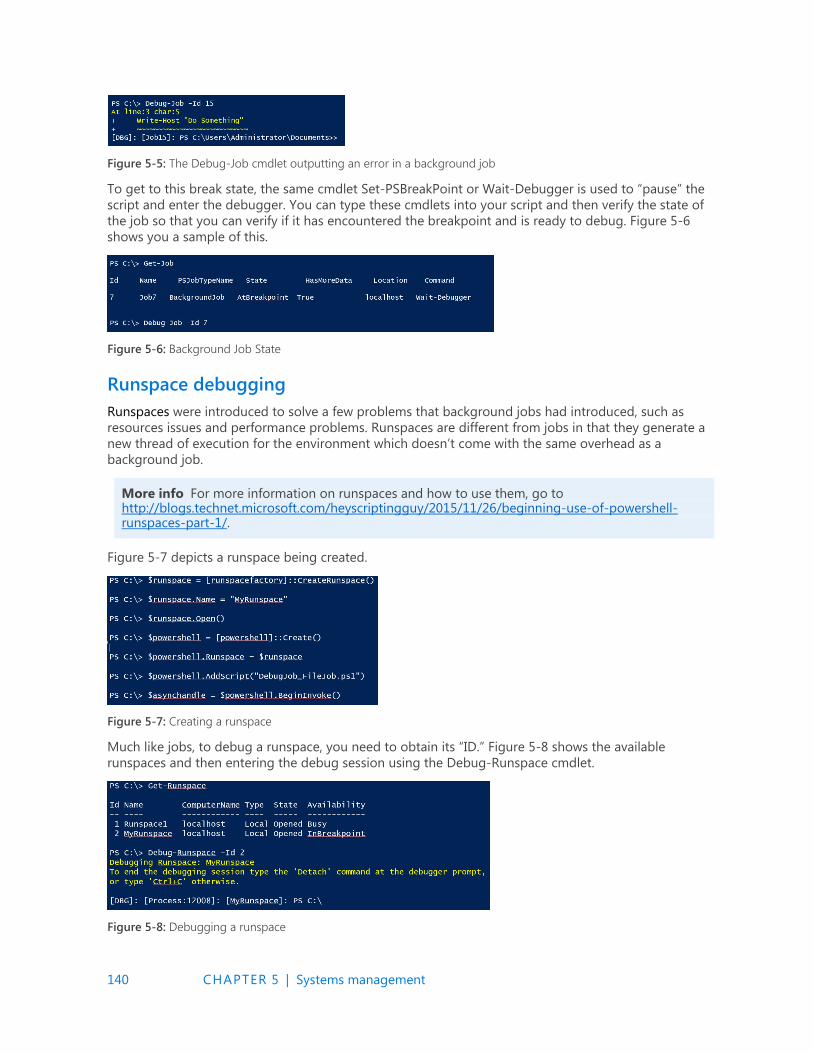
140 CHAPTER 5 | Systems management
Figure 5-5: The Debug-Job cmdlet outputting an error in a background job
To get to this break state, the same cmdlet Set-PSBreakPoint or Wait-Debugger is used to “pause” the
script and enter the debugger. You can type these cmdlets into your script and then verify the state of
the job so that you can verify if it has encountered the breakpoint and is ready to debug. Figure 5-6
shows you a sample of this.
Figure 5-6: Background Job State
Runspace debugging
Runspaces were introduced to solve a few problems that background jobs had introduced, such as
resources issues and performance problems. Runspaces are different from jobs in that they generate a
new thread of execution for the environment which doesn’t come with the same overhead as a
background job.
More info For more information on runspaces and how to use them, go to http://blogs.technet.microsoft.com/heyscriptingguy/2015/11/26/beginning-use-of-powershell-runspaces-part-1/.
Figure 5-7 depicts a runspace being created.
Figure 5-7: Creating a runspace
Much like jobs, to debug a runspace, you need to obtain its “ID.” Figure 5-8 shows the available
runspaces and then entering the debug session using the Debug-Runspace cmdlet.
Figure 5-8: Debugging a runspace
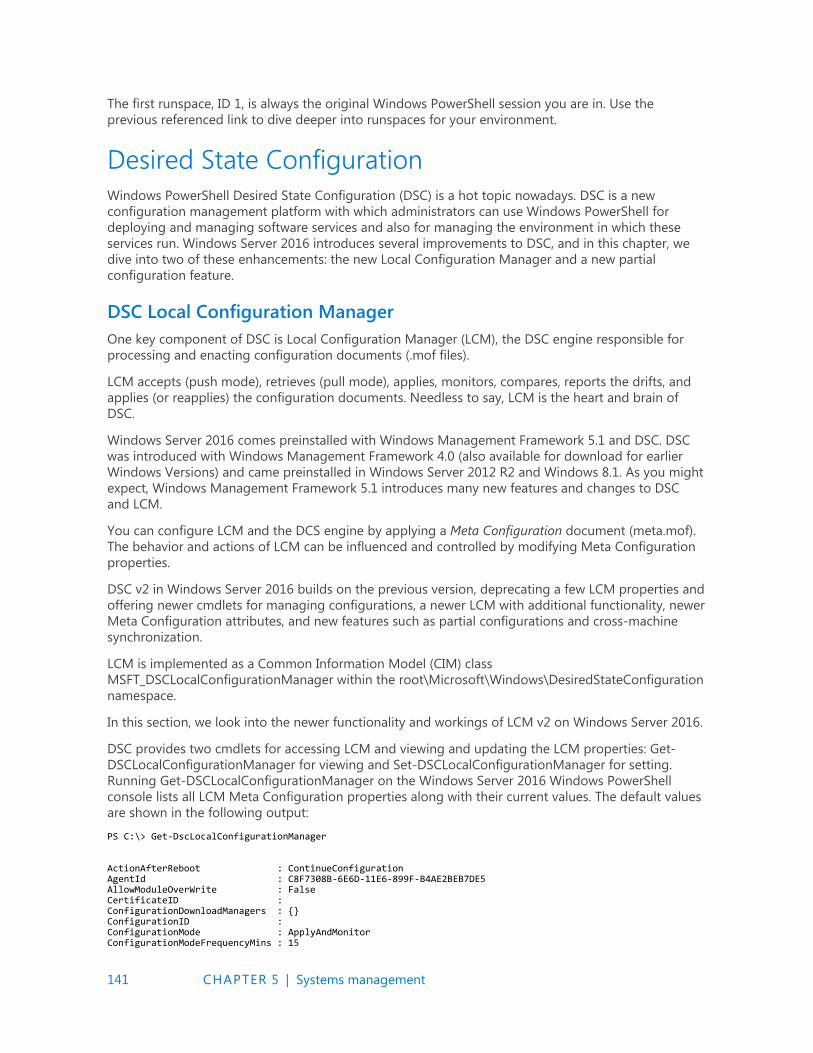
141 CHAPTER 5 | Systems management
The first runspace, ID 1, is always the original Windows PowerShell session you are in. Use the
previous referenced link to dive deeper into runspaces for your environment.
Desired State Configuration
Windows PowerShell Desired State Configuration (DSC) is a hot topic nowadays. DSC is a new
configuration management platform with which administrators can use Windows PowerShell for
deploying and managing software services and also for managing the environment in which these
services run. Windows Server 2016 introduces several improvements to DSC, and in this chapter, we
dive into two of these enhancements: the new Local Configuration Manager and a new partial
configuration feature.
DSC Local Configuration Manager
One key component of DSC is Local Configuration Manager (LCM), the DSC engine responsible for
processing and enacting configuration documents (.mof files).
LCM accepts (push mode), retrieves (pull mode), applies, monitors, compares, reports the drifts, and
applies (or reapplies) the configuration documents. Needless to say, LCM is the heart and brain of
DSC.
Windows Server 2016 comes preinstalled with Windows Management Framework 5.1 and DSC. DSC
was introduced with Windows Management Framework 4.0 (also available for download for earlier
Windows Versions) and came preinstalled in Windows Server 2012 R2 and Windows 8.1. As you might
expect, Windows Management Framework 5.1 introduces many new features and changes to DSC
and LCM.
You can configure LCM and the DCS engine by applying a Meta Configuration document (meta.mof).
The behavior and actions of LCM can be influenced and controlled by modifying Meta Configuration
properties.
DSC v2 in Windows Server 2016 builds on the previous version, deprecating a few LCM properties and
offering newer cmdlets for managing configurations, a newer LCM with additional functionality, newer
Meta Configuration attributes, and new features such as partial configurations and cross-machine
synchronization.
LCM is implemented as a Common Information Model (CIM) class
MSFT_DSCLocalConfigurationManager within the root\Microsoft\Windows\DesiredStateConfiguration
namespace.
In this section, we look into the newer functionality and workings of LCM v2 on Windows Server 2016.
DSC provides two cmdlets for accessing LCM and viewing and updating the LCM properties: Get-
DSCLocalConfigurationManager for viewing and Set-DSCLocalConfigurationManager for setting.
Running Get-DSCLocalConfigurationManager on the Windows Server 2016 Windows PowerShell
console lists all LCM Meta Configuration properties along with their current values. The default values
are shown in the following output:
PS C:\> Get-DscLocalConfigurationManager ActionAfterReboot : ContinueConfiguration AgentId : C8F7308B-6E6D-11E6-899F-B4AE2BEB7DE5 AllowModuleOverWrite : False CertificateID : ConfigurationDownloadManagers : {} ConfigurationID : ConfigurationMode : ApplyAndMonitor ConfigurationModeFrequencyMins : 15
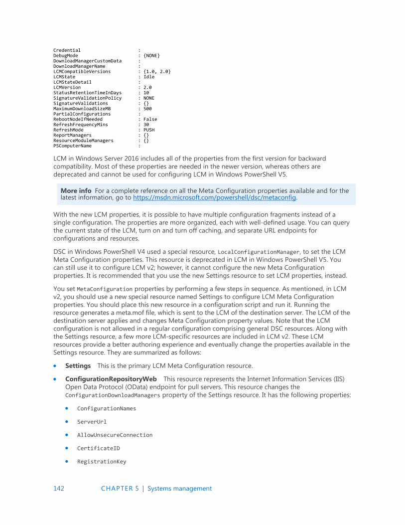
142 CHAPTER 5 | Systems management
Credential : DebugMode : {NONE} DownloadManagerCustomData : DownloadManagerName : LCMCompatibleVersions : {1.0, 2.0} LCMState : Idle LCMStateDetail : LCMVersion : 2.0 StatusRetentionTimeInDays : 10 SignatureValidationPolicy : NONE SignatureValidations : {} MaximumDownloadSizeMB : 500 PartialConfigurations : RebootNodeIfNeeded : False RefreshFrequencyMins : 30 RefreshMode : PUSH ReportManagers : {} ResourceModuleManagers : {} PSComputerName :
LCM in Windows Server 2016 includes all of the properties from the first version for backward
compatibility. Most of these properties are needed in the newer version, whereas others are
deprecated and cannot be used for configuring LCM in Windows PowerShell V5.
More info For a complete reference on all the Meta Configuration properties available and for the latest information, go to https://msdn.microsoft.com/powershell/dsc/metaconfig.
With the new LCM properties, it is possible to have multiple configuration fragments instead of a
single configuration. The properties are more organized, each with well-defined usage. You can query
the current state of the LCM, turn on and turn off caching, and separate URL endpoints for
configurations and resources.
DSC in Windows PowerShell V4 used a special resource, LocalConfigurationManager, to set the LCM
Meta Configuration properties. This resource is deprecated in LCM in Windows PowerShell V5. You
can still use it to configure LCM v2; however, it cannot configure the new Meta Configuration
properties. It is recommended that you use the new Settings resource to set LCM properties, instead.
You set MetaConfiguration properties by performing a few steps in sequence. As mentioned, in LCM
v2, you should use a new special resource named Settings to configure LCM Meta Configuration
properties. You should place this new resource in a configuration script and run it. Running the
resource generates a meta.mof file, which is sent to the LCM of the destination server. The LCM of the
destination server applies and changes Meta Configuration property values. Note that the LCM
configuration is not allowed in a regular configuration comprising general DSC resources. Along with
the Settings resource, a few more LCM-specific resources are included in LCM v2. These LCM
resources provide a better authoring experience and eventually change the properties available in the
Settings resource. They are summarized as follows:
Settings This is the primary LCM Meta Configuration resource.
ConfigurationRepositoryWeb This resource represents the Internet Information Services (IIS)
Open Data Protocol (OData) endpoint for pull servers. This resource changes the
ConfigurationDownloadManagers property of the Settings resource. It has the following properties:
ConfigurationNames
ServerUrl
AllowUnsecureConnection
CertificateID
RegistrationKey
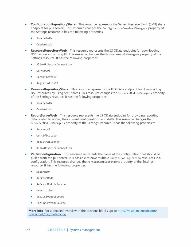
143 CHAPTER 5 | Systems management
ConfigurationRepositoryShare This resource represents the Server Message Block (SMB) share
endpoint for pull servers. This resource changes the ConfigurationDownloadManagers property of
the Settings resource. It has the following properties:
SourcePath
Credential
ResourceRepositoryWeb This resource represents the IIS OData endpoint for downloading
DSC resources by using IIS. This resource changes the ResourceModuleManagers property of the
Settings resource. It has the following properties:
AllowUnSecureConnection
ServerUrl
CertificateID
RegistrationID
ResourceRepositoryShare This resource represents the IIS OData endpoint for downloading
DSC resources by using SMB shares. This resource changes the ResourceModuleManagers property
of the Settings resource. It has the following properties:
SourcePath
Credential
ReportServerWeb This resource represents the IIS OData endpoint for providing reporting
data related to nodes, their current configurations, and drifts. This resource changes the
ResourceModuleManagers property of the Settings resource. It has the following properties:
ServerUrl
CertificateID
RegistrationKey
AllowUnsecureConnection
PartialConfiguration This resource represents the name of the configuration that should be
pulled from the pull server. It is possible to have multiple PartialConfiguration resources in a
configuration. This resource changes the PartialConfigurations property of the Settings
resource. It has the following properties:
DependsOn
RefreshMode
RefreshModuleSource
Description
ExclusiveResources
ConfigurationSource
More info For a detailed overview of the previous blocks, go to https://msdn.microsoft.com/ powershell/dsc/metaconfig.
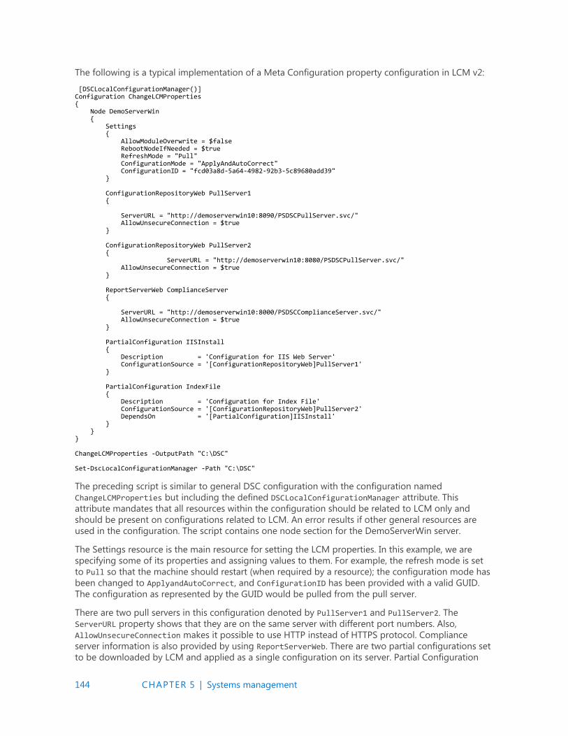
144 CHAPTER 5 | Systems management
The following is a typical implementation of a Meta Configuration property configuration in LCM v2:
[DSCLocalConfigurationManager()] Configuration ChangeLCMProperties { Node DemoServerWin { Settings { AllowModuleOverwrite = $false RebootNodeIfNeeded = $true RefreshMode = "Pull" ConfigurationMode = "ApplyAndAutoCorrect" ConfigurationID = "fcd03a8d-5a64-4982-92b3-5c89680add39" } ConfigurationRepositoryWeb PullServer1 { ServerURL = "http://demoserverwin10:8090/PSDSCPullServer.svc/" AllowUnsecureConnection = $true } ConfigurationRepositoryWeb PullServer2 { ServerURL = "http://demoserverwin10:8080/PSDSCPullServer.svc/" AllowUnsecureConnection = $true } ReportServerWeb ComplianceServer { ServerURL = "http://demoserverwin10:8000/PSDSCComplianceServer.svc/" AllowUnsecureConnection = $true } PartialConfiguration IISInstall { Description = 'Configuration for IIS Web Server' ConfigurationSource = '[ConfigurationRepositoryWeb]PullServer1' } PartialConfiguration IndexFile { Description = 'Configuration for Index File' ConfigurationSource = '[ConfigurationRepositoryWeb]PullServer2' DependsOn = '[PartialConfiguration]IISInstall' } } } ChangeLCMProperties -OutputPath "C:\DSC" Set-DscLocalConfigurationManager -Path "C:\DSC"
The preceding script is similar to general DSC configuration with the configuration named
ChangeLCMProperties but including the defined DSCLocalConfigurationManager attribute. This
attribute mandates that all resources within the configuration should be related to LCM only and
should be present on configurations related to LCM. An error results if other general resources are
used in the configuration. The script contains one node section for the DemoServerWin server.
The Settings resource is the main resource for setting the LCM properties. In this example, we are
specifying some of its properties and assigning values to them. For example, the refresh mode is set
to Pull so that the machine should restart (when required by a resource); the configuration mode has
been changed to ApplyandAutoCorrect, and ConfigurationID has been provided with a valid GUID.
The configuration as represented by the GUID would be pulled from the pull server.
There are two pull servers in this configuration denoted by PullServer1 and PullServer2. The
ServerURL property shows that they are on the same server with different port numbers. Also,
AllowUnsecureConnection makes it possible to use HTTP instead of HTTPS protocol. Compliance
server information is also provided by using ReportServerWeb. There are two partial configurations set
to be downloaded by LCM and applied as a single configuration on its server. Partial Configuration
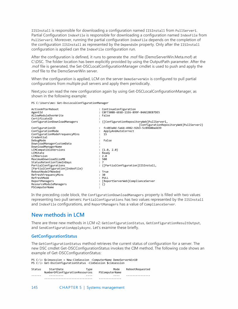
145 CHAPTER 5 | Systems management
IISInstall is responsible for downloading a configuration named IISInstall from PullServer1.
Partial Configuration IndexFile is responsible for downloading a configuration named IndexFile from
PullServer2. Moreover, running the partial configuration IndexFile depends on the completion of
the configuration IISInstall as represented by the DependsOn property. Only after the IISInstall
configuration is applied can the IndexFile configuration run.
After the configuration is defined, it runs to generate the .mof file (DemoServerWin.Meta.mof) at
C:\DSC. The folder location has been explicitly provided by using the OutputPath parameter. After the
.mof file is generated, the Set-DSCLocalConfigurationManager cmdlet is used to push and apply the
.mof file to the DemoServerWin server.
When the configuration is applied, LCM on the server DemoServerWin is configured to pull partial
configurations from multiple pull servers and apply them periodically.
Next,you can read the new configuration again by using Get-DSCLocalConfigurationManager, as
shown in the following example:
PS C:\Users\me> Get-DscLocalConfigurationManager ActionAfterReboot : ContinueConfiguration AgentId : C8F7308B-6E6D-11E6-899F-B4AE2BEB7DE5 AllowModuleOverWrite : False CertificateID : ConfigurationDownloadManagers : {[ConfigurationRepositoryWeb]PullServer1, [ConfigurationRepositoryWeb]PullServer2} ConfigurationID : fcd03a8d-5a64-4982-92b3-5c89680add39 ConfigurationMode : ApplyAndAutoCorrect ConfigurationModeFrequencyMins : 15 Credential : DebugMode : False DownloadManagerCustomData : DownloadManagerName : LCMCompatibleVersions : {1.0, 2.0} LCMState : Ready LCMVersion : 2.0 MaximumDownloadSizeMB : 500 StatusRetentionTimeInDays : 7 PartialConfigurations : {[PartialConfiguration]IISInstall, [PartialConfiguration]IndexFile} RebootNodeIfNeeded : True RefreshFrequencyMins : 30 RefreshMode : PULL ReportManagers : [ReportServerWeb]ComplianceServer ResourceModuleManagers : {} PSComputerName :
In the preceding code block, the ConfigurationDownloadManagers property is filled with two values
representing two pull servers: PartialConfigurations has two values represented by the IISInstall
and IndexFile configurations, and ReportManagers has a value of ComplianceServer.
New methods in LCM
There are three new methods in LCM v2: GetConfigurationStatus, GetConfigurationResultOutput,
and SendConfigurationApplyAsync. Let's examine these briefly.
GetConfigurationStatus
The GetConfigurationStatus method retrieves the current status of configuration for a server. The
new DSC cmdlet Get-DSCConfigurationStatus invokes the CIM method. The following code shows an
example of Get-DSCConfigurationStatus:
PS C:\> $cimsession = New-CimSession -ComputerName DemoServerWin10 PS C:\> Get-DscConfigurationStatus -CimSession $cimsession Status StartDate Type Mode RebootRequested NumberOfConfigurationResources PSComputerName ------ --------- ---- ---- --------------- ------------------------------ --------------
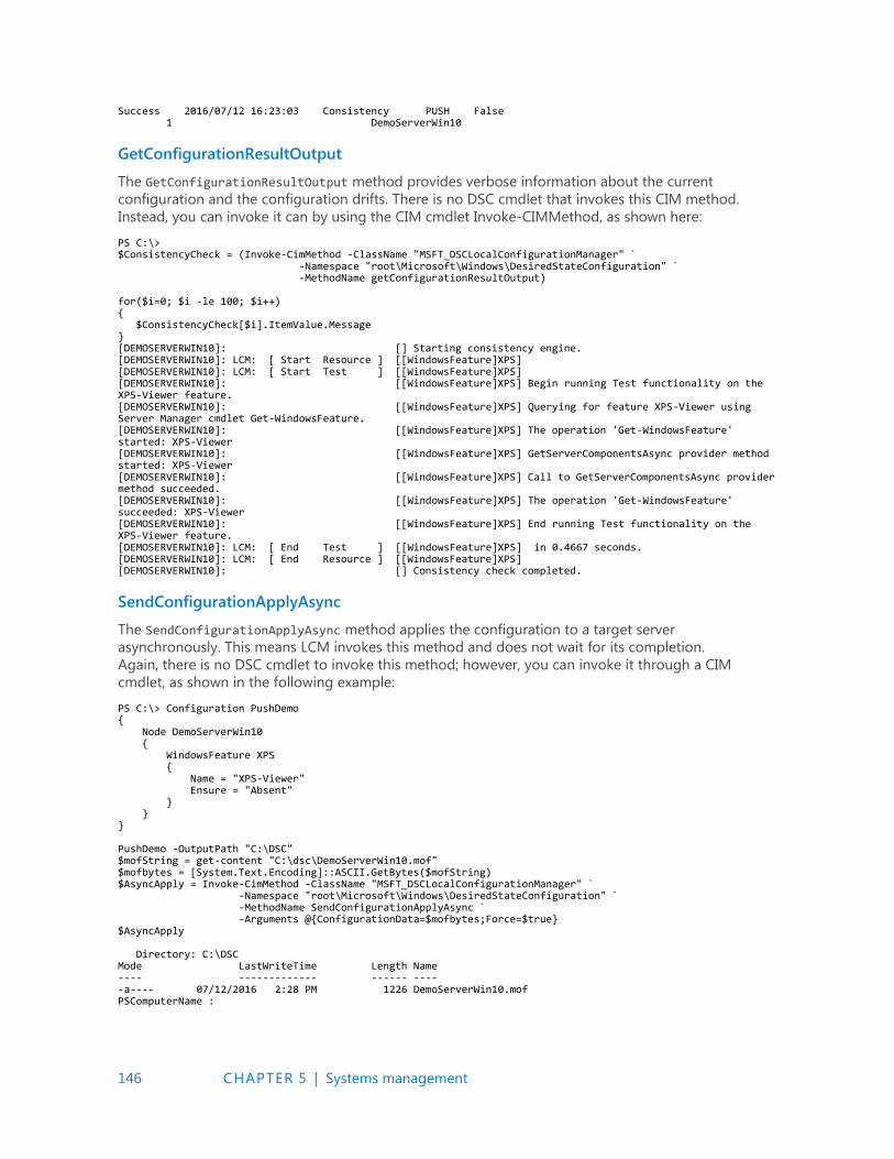
146 CHAPTER 5 | Systems management
Success 2016/07/12 16:23:03 Consistency PUSH False 1 DemoServerWin10
GetConfigurationResultOutput
The GetConfigurationResultOutput method provides verbose information about the current
configuration and the configuration drifts. There is no DSC cmdlet that invokes this CIM method.
Instead, you can invoke it can by using the CIM cmdlet Invoke-CIMMethod, as shown here:
PS C:\> $ConsistencyCheck = (Invoke-CimMethod -ClassName "MSFT_DSCLocalConfigurationManager" ` -Namespace "root\Microsoft\Windows\DesiredStateConfiguration" ` -MethodName getConfigurationResultOutput) for($i=0; $i -le 100; $i++) { $ConsistencyCheck[$i].ItemValue.Message } [DEMOSERVERWIN10]: [] Starting consistency engine. [DEMOSERVERWIN10]: LCM: [ Start Resource ] [[WindowsFeature]XPS] [DEMOSERVERWIN10]: LCM: [ Start Test ] [[WindowsFeature]XPS] [DEMOSERVERWIN10]: [[WindowsFeature]XPS] Begin running Test functionality on the XPS-Viewer feature. [DEMOSERVERWIN10]: [[WindowsFeature]XPS] Querying for feature XPS-Viewer using Server Manager cmdlet Get-WindowsFeature. [DEMOSERVERWIN10]: [[WindowsFeature]XPS] The operation 'Get-WindowsFeature' started: XPS-Viewer [DEMOSERVERWIN10]: [[WindowsFeature]XPS] GetServerComponentsAsync provider method started: XPS-Viewer [DEMOSERVERWIN10]: [[WindowsFeature]XPS] Call to GetServerComponentsAsync provider method succeeded. [DEMOSERVERWIN10]: [[WindowsFeature]XPS] The operation 'Get-WindowsFeature' succeeded: XPS-Viewer [DEMOSERVERWIN10]: [[WindowsFeature]XPS] End running Test functionality on the XPS-Viewer feature. [DEMOSERVERWIN10]: LCM: [ End Test ] [[WindowsFeature]XPS] in 0.4667 seconds. [DEMOSERVERWIN10]: LCM: [ End Resource ] [[WindowsFeature]XPS] [DEMOSERVERWIN10]: [] Consistency check completed.
SendConfigurationApplyAsync
The SendConfigurationApplyAsync method applies the configuration to a target server
asynchronously. This means LCM invokes this method and does not wait for its completion.
Again, there is no DSC cmdlet to invoke this method; however, you can invoke it through a CIM
cmdlet, as shown in the following example:
PS C:\> Configuration PushDemo { Node DemoServerWin10 { WindowsFeature XPS { Name = "XPS-Viewer" Ensure = "Absent" } } } PushDemo -OutputPath "C:\DSC" $mofString = get-content "C:\dsc\DemoServerWin10.mof" $mofbytes = [System.Text.Encoding]::ASCII.GetBytes($mofString) $AsyncApply = Invoke-CimMethod -ClassName "MSFT_DSCLocalConfigurationManager" ` -Namespace "root\Microsoft\Windows\DesiredStateConfiguration" ` -MethodName SendConfigurationApplyAsync ` -Arguments @{ConfigurationData=$mofbytes;Force=$true} $AsyncApply Directory: C:\DSC Mode LastWriteTime Length Name ---- ------------- ------ ---- -a---- 07/12/2016 2:28 PM 1226 DemoServerWin10.mof PSComputerName :
147 CHAPTER 5 | Systems management
DSC partial configurations
One of the most awaited and interesting features of DSC v2 is partial configuration. Until DSC v2, it
was difficult to split a configuration into multiple configuration files authored for a server. Partial
configuration makes it possible for you to split a configuration into multiple smaller configuration
fragments across multiple files. Partial configurations are implemented exactly the same as any
general DSC configuration. It is the responsibility of LCM on a destination server to combine all the
configuration fragments into a single configuration and apply it.
Partial configurations are complete in and of themselves, and you can apply them independently as a
complete configuration to any server. It is the LCM Meta Configuration that’s configured on the target
server that makes it possible for partial configurations to be applied to a server.
In Windows Server 2016, partial configurations work within DSC push and pull mode. This means that
you should configure the LCM of servers in a network to pull configurations from a pull server (IIS or
SMB share) and be able to identify the configurations distinctly on these pull servers.
The benefits of partial configurations include the following:
Multiple authors can write configurations independently and simultaneously for servers in a
network.
You can apply incremental configurations to servers without modifying any existing
configurations.
Modular authoring of configurations is available.
There are no longer dependencies on using only a single .mof file. This was the case in DSC v1, for
which only one .mof file was allowed and applied to a server at a given point of time. Newer
configuration (.mof) would replace the current configuration in DSC v1.
To make partial configuration work in Windows Server 2016, complete the following steps:
1. Create the pull server.
2. Configure the LCM Meta Configuration of servers on the network.
3. Author the configurations.
4. Deploy the configurations on the pull server.
We will look into the details of each of these steps, except for the creation of the pull server because
that process is the same as for DSC v1.
Setting up the LCM Meta Configuration
To prepare a server’s LCM Meta Configuration, you must set the following:
RefreshMode with the value of Pull.
ConfigurationMode with any value to keep the server in the expected state.
ConfigurationRepositoryWeb resource instance representing a pull server of either web or SMB.
Multiple PartialConfiguration resource instances, each representing a configuration on a pull
server.
In LCM, another Meta Configuration property you need to decide to set can be either
ConfigurationID or ConfigurationName. Visit the following two links in reference to both properties:
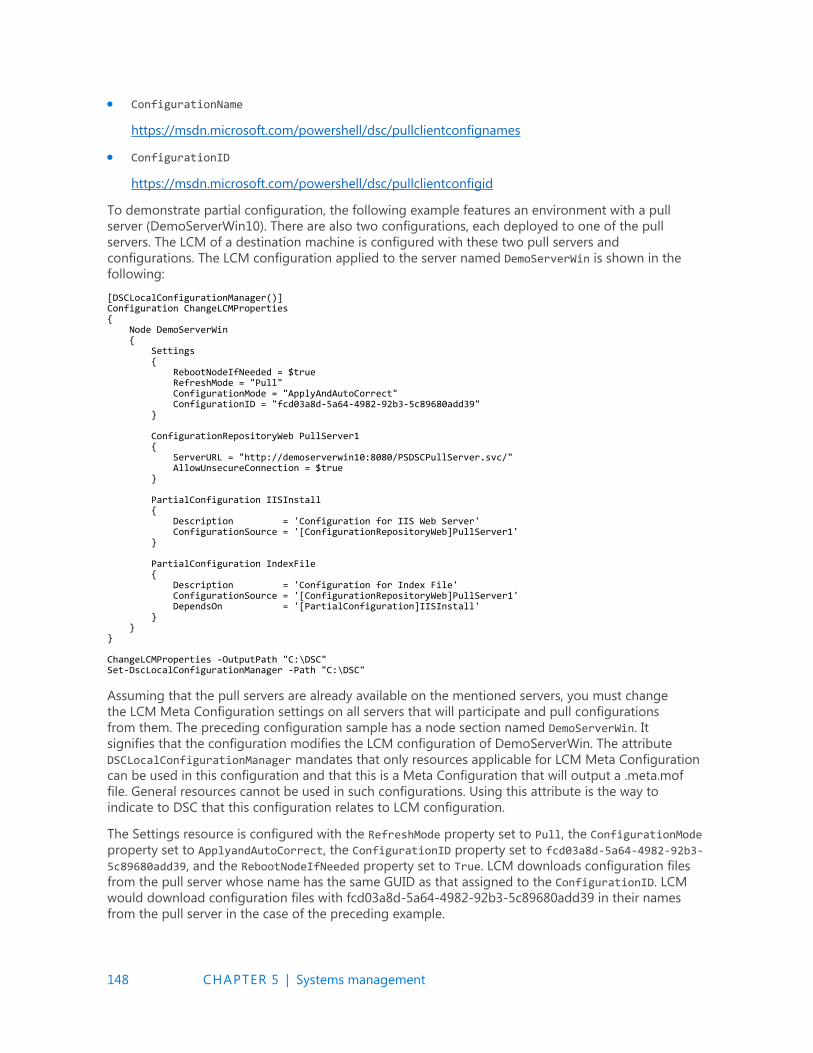
148 CHAPTER 5 | Systems management
ConfigurationName
https://msdn.microsoft.com/powershell/dsc/pullclientconfignames
ConfigurationID
https://msdn.microsoft.com/powershell/dsc/pullclientconfigid
To demonstrate partial configuration, the following example features an environment with a pull
server (DemoServerWin10). There are also two configurations, each deployed to one of the pull
servers. The LCM of a destination machine is configured with these two pull servers and
configurations. The LCM configuration applied to the server named DemoServerWin is shown in the
following:
[DSCLocalConfigurationManager()] Configuration ChangeLCMProperties { Node DemoServerWin { Settings { RebootNodeIfNeeded = $true RefreshMode = "Pull" ConfigurationMode = "ApplyAndAutoCorrect" ConfigurationID = "fcd03a8d-5a64-4982-92b3-5c89680add39" } ConfigurationRepositoryWeb PullServer1 { ServerURL = "http://demoserverwin10:8080/PSDSCPullServer.svc/" AllowUnsecureConnection = $true } PartialConfiguration IISInstall { Description = 'Configuration for IIS Web Server' ConfigurationSource = '[ConfigurationRepositoryWeb]PullServer1' } PartialConfiguration IndexFile { Description = 'Configuration for Index File' ConfigurationSource = '[ConfigurationRepositoryWeb]PullServer1' DependsOn = '[PartialConfiguration]IISInstall' } } } ChangeLCMProperties -OutputPath "C:\DSC" Set-DscLocalConfigurationManager -Path "C:\DSC"
Assuming that the pull servers are already available on the mentioned servers, you must change
the LCM Meta Configuration settings on all servers that will participate and pull configurations
from them. The preceding configuration sample has a node section named DemoServerWin. It
signifies that the configuration modifies the LCM configuration of DemoServerWin. The attribute
DSCLocalConfigurationManager mandates that only resources applicable for LCM Meta Configuration
can be used in this configuration and that this is a Meta Configuration that will output a .meta.mof
file. General resources cannot be used in such configurations. Using this attribute is the way to
indicate to DSC that this configuration relates to LCM configuration.
The Settings resource is configured with the RefreshMode property set to Pull, the ConfigurationMode
property set to ApplyandAutoCorrect, the ConfigurationID property set to fcd03a8d-5a64-4982-92b3-
5c89680add39, and the RebootNodeIfNeeded property set to True. LCM downloads configuration files
from the pull server whose name has the same GUID as that assigned to the ConfigurationID. LCM
would download configuration files with fcd03a8d-5a64-4982-92b3-5c89680add39 in their names
from the pull server in the case of the preceding example.
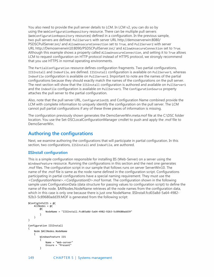
149 CHAPTER 5 | Systems management
You also need to provide the pull server details to LCM. In LCM v2, you can do so by
using the WebConfigurationRepository resource. There can be multiple pull servers
(WebConfigurationRepository resources) defined in a configuration. In the previous sample,
two pull servers are defined: PullServer1 with server URL http://demoserverwin:8080/
PSDSCPullServer.svc/ and AllowUnsecureConnection set to True, and PullServer2 with server
URL http://Demoserverwin10:8090/PSDSCPullServer.svc/ and AllowUnsecureConnection set to True.
Although this example shows a property called AllowUnsecureConnection, and setting it to True allows
LCM to request configuration on HTTP protocol instead of HTTPS protocol, we strongly recommend
that you use HTTPS in normal operating environments.
The PartialConfiguration resource defines configuration fragments. Two partial configurations,
IISInstall and IndexFile, are defined. IISInstall configuration is available on PullServer1, whereas
IndexFile configuration is available on PullServer2. Important to note are the names of the partial
configurations because they should exactly match the names of the configurations on the pull server.
The next section will show that the IISInstall configuration is authored and available on PullServer1
and the IndexFile configuration is available on PullServer1. The ConfigurationSource property
attaches the pull server to the partial configuration.
Also, note that the pull server URL, ConfigurationID, and Configuration Name combined provide the
LCM with complete information to uniquely identify the configuration on the pull server. The LCM
cannot pull partial configurations if any of these three pieces of information is missing.
The configuration previously shown generates the DemoServerWin.meta.mof file at the C:\DSC folder
location. You use the Set-DSCLocalConfigurationManager cmdlet to push and apply the .mof file to
DemoServerWin.
Authoring the configurations
Next, we examine authoring the configurations that will participate in partial configuration. In this
section, two configurations, IISInstall and IndexFile, are authored.
IISInstall configuration
This is a simple configuration responsible for installing IIS (Web-Server) on a server using the
WindowsFeature resource. Running the configurations in this section and the next one generates
.mof files. The configuration script in our sample that follows runs on server ServerWin10. The
name of the .mof file is same as the node name defined in the configuration script. Configurations
participating in partial configurations have a special naming requirement. They must use the
<ConfigurationName>.<ConfigurationID>.mof format. The configuration shown in the following
sample uses ConfigurationData (data structure for passing values to configuration script) to define the
name of the node. $AllNodes.NodeName retrieves all the node names from the configuration data,
which in this case is only one because there is just one NodeName. IISInstall.fcd03a8d-5a64-4982-
92b3-5c89680add39.MOF is generated from the following script:
$ConfigInfoIIS = @{ AllNodes = @( @{ NodeName = "IISInstall.fcd03a8d-5a64-4982-92b3-5c89680add39" } ) } Configuration IISInstall { Node $AllNodes.NodeName { WindowsFeature IIS { Name = "Web-server" Ensure = "Present" }

150 CHAPTER 5 | Systems management
} } IISInstall -OutputPath 'C:\Program Files\WindowsPowerShell\DscService\Configuration' -ConfigurationData $ConfigInfoIIS New-DSCCheckSum -ConfigurationPath 'C:\Program Files\WindowsPowerShell\DscService\Configuration' -OutPath 'C:\Program Files\WindowsPowerShell\DscService\Configuration'
You should place the .mof files on pull server WinServer10 in a well-defined folder, typically in
C:\Program Files\WindowsPowerShell\DSCService\Configuration. When the .mof file is generated, this
folder location is passed as a parameter for the OutPath attribute.
After .mof file generation, the checksum file for the configuration needs to be generated. The
checksum determines if a new configuration exists on the pull server or not. It also helps to verify the
integrity of configurations when they are transmitted between the pull server and the LCM. The
checksum file must have the same name as the .mof file with .mof.checksum as an extension. DSC
provides the New-DSCCheckSum cmdlet to generate the checksum file. The ConfigurationPath
parameter specifies the folder location where configurations are stored. The cmdlet generates a
checksum file for each configuration and saves the checksum in the folder location specified by the
OutPath parameter.
IndexFile configuration
IndexFile is a simple configuration responsible for generating an Index.htm file on a server at the IIS
default root directory (C:\Inetpubwwwroot\). The purpose of this file is to show a “Website under
maintainence” message to users. It uses a File resource and creates a file named Index.htm in the
C:\Inetpub\wwwroot folder with HTML content displaying, in this example, “If you are seeing this
page, it means the website is under maintenance and DSC Rocks!!!!!” The configuration script that
follows runs on the DemoServerWin10 server. The name is IndexFile.fcd03a8d-5a64-4982-92b3-
5c89680add39, and this is the same GUID value shown earlier for the IISInstall configuration
example.
$ConfigInfoIndex = @{ AllNodes = @( @{ NodeName = "IndexFile.fcd03a8d-5a64-4982-92b3-5c89680add39" } ) } Configuration IndexFile { Node $AllNodes.NodeName { File IndexFile { DestinationPath = "C:\inetpub\wwwroot\index.htm" Ensure = "Present" Type = "File" Force = $true Contents = "<HTML><HEAD><Title> Website under construction.</Title></HEAD><BODY> ` <h1>If you are seeing this page, it means the website is under maintenance and DSC Rocks !!!!!</h1></BODY></HTML>" } } } IndexFile -OutputPath 'C:\Program Files\WindowsPowerShell\DscService\Configuration' -ConfigurationData $ConfigInfoIndex New-DSCCheckSum -ConfigurationPath 'C:\Program Files\WindowsPowerShell\DscService\Configuration' -OutPath 'C:\Program Files\WindowsPowerShell\DscService\Configuration'
To function, the Configuration IndexFile must match the partial configuration defined in the Meta
Configuration.
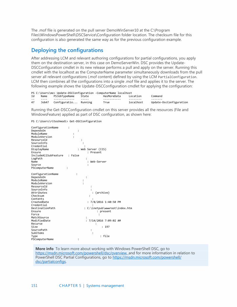
151 CHAPTER 5 | Systems management
The .mof file is generated on the pull server DemoWinServer10 at the C:\Program
Files\WindowsPowerShell\DSCService\Configuration folder location. The checksum file for this
configuration is also generated the same way as for the previous configuration example.
Deploying the configurations
After addressing LCM and relevant authoring configurations for partial configurations, you apply
them on the destination server, in this case on DemoServerWin. DSC provides the Update-
DSCConfiguration cmdlet in its new release performs a pull and apply on the server. Running this
cmdlet with the localhost as the ComputerName parameter simultaneously downloads from the pull
server all relevant configurations (.mof content) defined by using the LCM PartialConfiguration.
LCM then combines all the configurations into a single .mof file and applies it to the server. The
following example shows the Update-DSCConfiguration cmdlet for applying the configuration:
PS C:\Users\me> Update-DSCConfiguration -ComputerName localhost Id Name PSJobTypeName State HasMoreData Location Command -- ---- ------------- ----- ----------- -------- ------- 47 Job47 Configuratio... Running True localhost Update-DscConfiguration
Running the Get-DSCConfiguration cmdlet on this server provides all the resources (File and
WindowsFeature) applied as part of DSC configuration, as shown here:
PS C:\Users\riteshmodi> Get-DSCConfiguration ConfigurationName : DependsOn : ModuleName : ModuleVersion : ResourceId : SourceInfo : Credential : DisplayName : Web Server (IIS) Ensure : Present IncludeAllSubFeature : False LogPath : Name : Web-Server Source : PSComputerName : ConfigurationName : DependsOn : ModuleName : ModuleVersion : ResourceId : SourceInfo : Attributes : {archive} Checksum : Contents : CreatedDate : 7/8/2016 1:40:50 PM Credential : DestinationPath : C:\inetpub\wwwroot\index.htm Ensure : present Force : MatchSource : ModifiedDate : 7/14/2016 7:09:02 AM Recurse : Size : 197 SourcePath : SubItems : Type : file PSComputerName :
More info To learn more about working with Windows PowerShell DSC, go to https://msdn.microsoft.com/powershell/dsc/overview, and for more information in relation to PowerShell DSC Partial Configurations, go to https://msdn.microsoft.com/powershell/ dsc/partialconfigs.
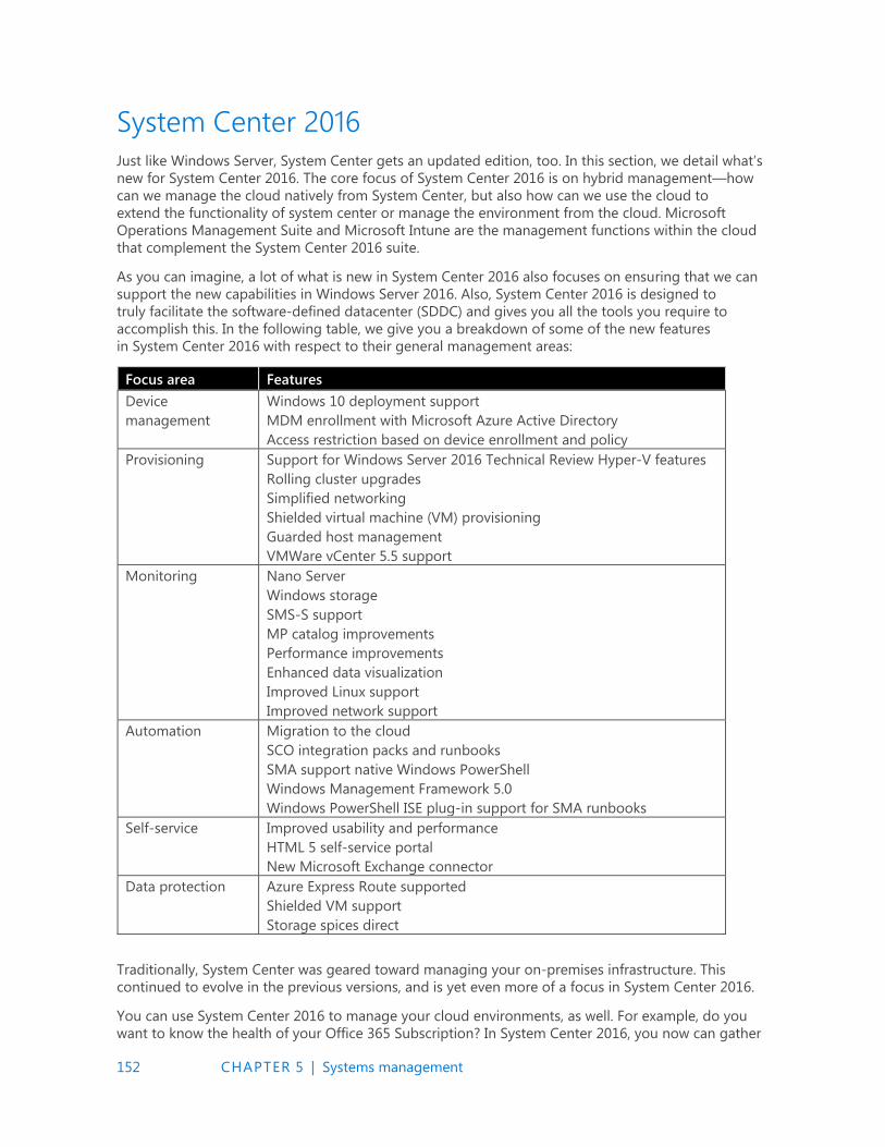
152 CHAPTER 5 | Systems management
System Center 2016
Just like Windows Server, System Center gets an updated edition, too. In this section, we detail what’s
new for System Center 2016. The core focus of System Center 2016 is on hybrid management—how
can we manage the cloud natively from System Center, but also how can we use the cloud to
extend the functionality of system center or manage the environment from the cloud. Microsoft
Operations Management Suite and Microsoft Intune are the management functions within the cloud
that complement the System Center 2016 suite.
As you can imagine, a lot of what is new in System Center 2016 also focuses on ensuring that we can
support the new capabilities in Windows Server 2016. Also, System Center 2016 is designed to
truly facilitate the software-defined datacenter (SDDC) and gives you all the tools you require to
accomplish this. In the following table, we give you a breakdown of some of the new features
in System Center 2016 with respect to their general management areas:
Focus area Features
Device
management
Windows 10 deployment support
MDM enrollment with Microsoft Azure Active Directory
Access restriction based on device enrollment and policy
Provisioning Support for Windows Server 2016 Technical Review Hyper-V features
Rolling cluster upgrades
Simplified networking
Shielded virtual machine (VM) provisioning
Guarded host management
VMWare vCenter 5.5 support
Monitoring Nano Server
Windows storage
SMS-S support
MP catalog improvements
Performance improvements
Enhanced data visualization
Improved Linux support
Improved network support
Automation Migration to the cloud
SCO integration packs and runbooks
SMA support native Windows PowerShell
Windows Management Framework 5.0
Windows PowerShell ISE plug-in support for SMA runbooks
Self-service Improved usability and performance
HTML 5 self-service portal
New Microsoft Exchange connector
Data protection Azure Express Route supported
Shielded VM support
Storage spices direct
Traditionally, System Center was geared toward managing your on-premises infrastructure. This
continued to evolve in the previous versions, and is yet even more of a focus in System Center 2016.
You can use System Center 2016 to manage your cloud environments, as well. For example, do you
want to know the health of your Office 365 Subscription? In System Center 2016, you now can gather
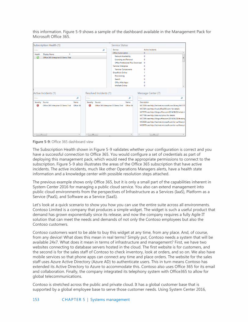
153 CHAPTER 5 | Systems management
this information. Figure 5-9 shows a sample of the dashboard available in the Management Pack for
Microsoft Office 365.
Figure 5-9: Office 365 dashboard view
The Subscription Health shown in Figure 5-9 validates whether your configuration is correct and you
have a successful connection to Office 365. You would configure a set of credentials as part of
deploying this management pack, which would need the appropriate permissions to connect to the
subscription. Figure 5-9 also illustrates the areas of the Office 365 subscription that have active
incidents. The active incidents, much like other Operations Managers alerts, have a health state
information and a knowledge center with possible resolution steps attached.
The previous example shows only Office 365, but it is only a small part of the capabilities inherent in
System Center 2016 for managing a public cloud service. You also can extend management into
public cloud environments from the perspectives of Infrastructure as a Services (IaaS), Platform as a
Service (PaaS), and Software as a Service (SaaS).
Let’s look at a quick scenario to show you how you can use the entire suite across all environments.
Contoso Limited is a company that produces a simple widget. The widget is such a useful product that
demand has grown exponentially since its release, and now the company requires a fully Agile IT
solution that can meet the needs and demands of not only the Contoso employees but also the
Contoso customers.
Contoso customers want to be able to buy this widget at any time, from any place. And, of course,
from any device! What does this mean in real terms? Simply put, Contoso needs a system that will be
available 24x7. What does it mean in terms of infrastructure and management? First, we have two
websites connecting to database servers hosted in the cloud. The first website is for customers, and
the second is for the sales staff of Contoso to check inventory, look at orders, and so on. We also have
mobile services so that phone apps can connect any time and place orders. The website for the sales
staff uses Azure Active Directory (Azure AD) to authenticate users. This in turn means Contoso has
extended its Active Directory to Azure to accommodate this. Contoso also uses Office 365 for its email
and collaboration. Finally, the company integrated its telephony system with Office365 to allow for
global telecommunications.
Contoso is stretched across the public and private cloud. It has a global customer base that is
supported by a global employee base to serve those customer needs. Using System Center 2016,
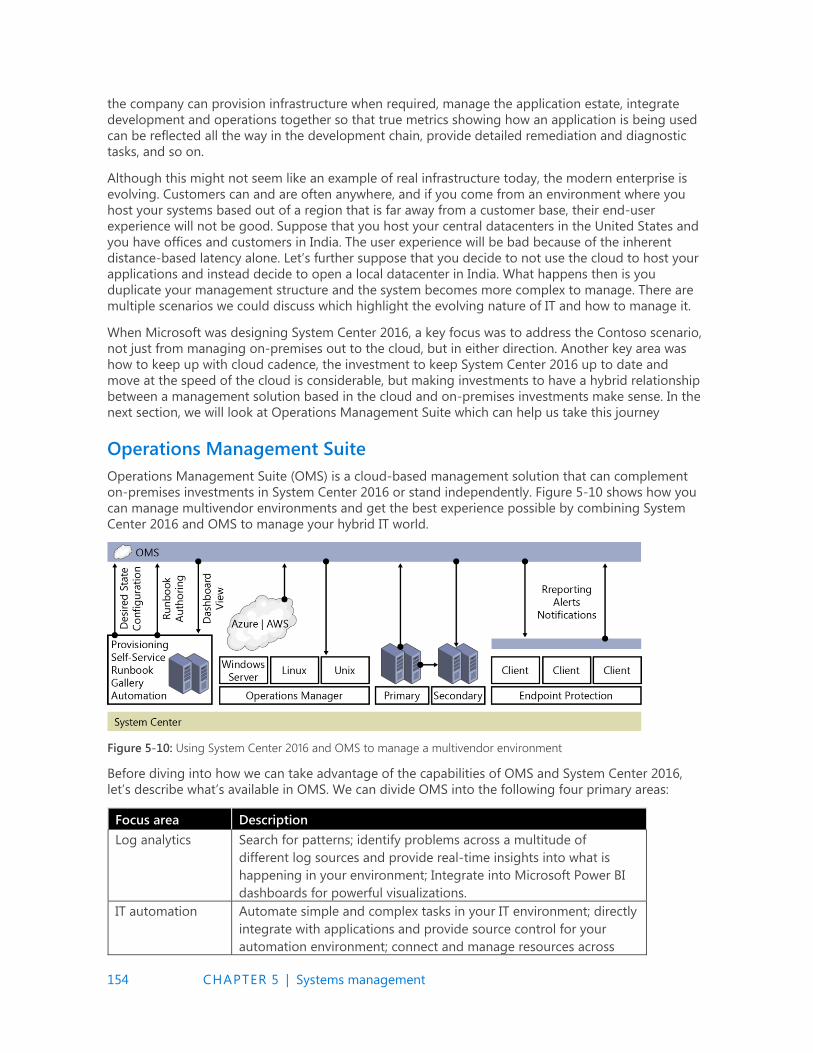
154 CHAPTER 5 | Systems management
the company can provision infrastructure when required, manage the application estate, integrate
development and operations together so that true metrics showing how an application is being used
can be reflected all the way in the development chain, provide detailed remediation and diagnostic
tasks, and so on.
Although this might not seem like an example of real infrastructure today, the modern enterprise is
evolving. Customers can and are often anywhere, and if you come from an environment where you
host your systems based out of a region that is far away from a customer base, their end-user
experience will not be good. Suppose that you host your central datacenters in the United States and
you have offices and customers in India. The user experience will be bad because of the inherent
distance-based latency alone. Let’s further suppose that you decide to not use the cloud to host your
applications and instead decide to open a local datacenter in India. What happens then is you
duplicate your management structure and the system becomes more complex to manage. There are
multiple scenarios we could discuss which highlight the evolving nature of IT and how to manage it.
When Microsoft was designing System Center 2016, a key focus was to address the Contoso scenario,
not just from managing on-premises out to the cloud, but in either direction. Another key area was
how to keep up with cloud cadence, the investment to keep System Center 2016 up to date and
move at the speed of the cloud is considerable, but making investments to have a hybrid relationship
between a management solution based in the cloud and on-premises investments make sense. In the
next section, we will look at Operations Management Suite which can help us take this journey
Operations Management Suite
Operations Management Suite (OMS) is a cloud-based management solution that can complement
on-premises investments in System Center 2016 or stand independently. Figure 5-10 shows how you
can manage multivendor environments and get the best experience possible by combining System
Center 2016 and OMS to manage your hybrid IT world.
Figure 5-10: Using System Center 2016 and OMS to manage a multivendor environment
Before diving into how we can take advantage of the capabilities of OMS and System Center 2016,
let’s describe what’s available in OMS. We can divide OMS into the following four primary areas:
Focus area Description
Log analytics Search for patterns; identify problems across a multitude of
different log sources and provide real-time insights into what is
happening in your environment; Integrate into Microsoft Power BI
dashboards for powerful visualizations.
IT automation Automate simple and complex tasks in your IT environment; directly
integrate with applications and provide source control for your
automation environment; connect and manage resources across

155 CHAPTER 5 | Systems management
datacenters.
Backup and
recovery
Back up your workloads directly to the cloud and use the cloud as a
recovery point. Alternatively, replicate your workloads from VMware
or Hyper-V and use the cloud as a recovery site.
Security and
compliance
Continually assess and understand what is happening in your
environment, from who is signing in to a new risk that is highlighted
in your environment.
The key takeaway here is the ability to be hybrid. This is particularly relevant if you have made a large
investment on-premises and want to use OMS and its features along with System Center 2016. Even if
you haven’t made any investment into System Center on-premises but like what OMS can offer, no
problem: You can take advantage of OMS to manage your existing cloud or on-premises estates.
To begin, whether you have OMS deployed or not, you must create an OMS workspace. To do so, sign
in to https://portal.azure.com, and then click New. Next, type Log Analytics (OMS), click Log
Analytics (OMS) (see Figure 5-11), and then click Create on the next page.
Figure 5-11: Creating your OMS workspace, part 1
This will open the OMS Workspace dialog box; you will need to populate the settings to match those
shown in Figure 5-12 and then click Create Workspace. You have a choice of tier; for most users, the
Free tier is a great way to explore the power and benefits of OMS.
Figure 5-12: Creating your OMS workspace, part 2
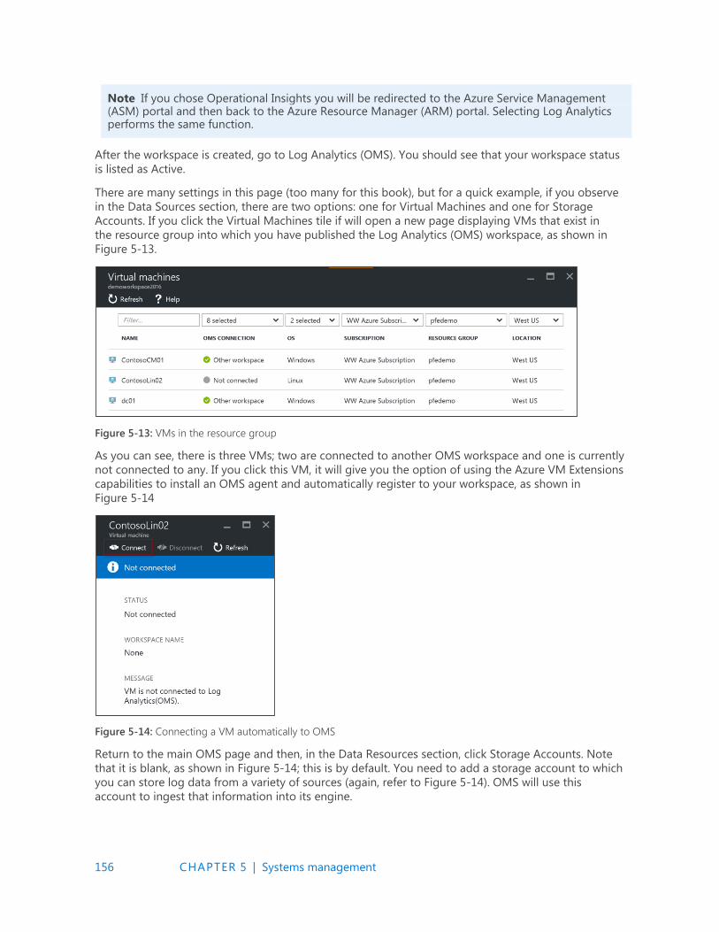
156 CHAPTER 5 | Systems management
Note If you chose Operational Insights you will be redirected to the Azure Service Management (ASM) portal and then back to the Azure Resource Manager (ARM) portal. Selecting Log Analytics performs the same function.
After the workspace is created, go to Log Analytics (OMS). You should see that your workspace status
is listed as Active.
There are many settings in this page (too many for this book), but for a quick example, if you observe
in the Data Sources section, there are two options: one for Virtual Machines and one for Storage
Accounts. If you click the Virtual Machines tile if will open a new page displaying VMs that exist in
the resource group into which you have published the Log Analytics (OMS) workspace, as shown in
Figure 5-13.
Figure 5-13: VMs in the resource group
As you can see, there is three VMs; two are connected to another OMS workspace and one is currently
not connected to any. If you click this VM, it will give you the option of using the Azure VM Extensions
capabilities to install an OMS agent and automatically register to your workspace, as shown in
Figure 5-14
Figure 5-14: Connecting a VM automatically to OMS
Return to the main OMS page and then, in the Data Resources section, click Storage Accounts. Note
that it is blank, as shown in Figure 5-14; this is by default. You need to add a storage account to which
you can store log data from a variety of sources (again, refer to Figure 5-14). OMS will use this
account to ingest that information into its engine.
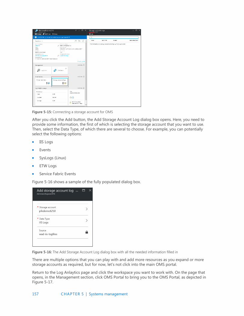
157 CHAPTER 5 | Systems management
Figure 5-15: Connecting a storage account for OMS
After you click the Add button, the Add Storage Account Log dialog box opens. Here, you need to
provide some information, the first of which is selecting the storage account that you want to use.
Then, select the Data Type, of which there are several to choose. For example, you can potentially
select the following options:
IIS Logs
Events
SysLogs (Linux)
ETW Logs
Service Fabric Events
Figure 5-16 shows a sample of the fully populated dialog box.
Figure 5-16: The Add Storage Account Log dialog box with all the needed information filled in
There are multiple options that you can play with and add more resources as you expand or more
storage accounts as required, but for now, let’s not click into the main OMS portal.
Return to the Log Anlaytics page and click the workspace you want to work with. On the page that
opens, in the Management section, click OMS Portal to bring you to the OMS Portal, as depicted in
Figure 5-17.
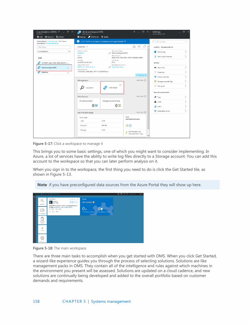
158 CHAPTER 5 | Systems management
Figure 5-17: Click a workspace to manage it
This brings you to some basic settings, one of which you might want to consider implementing. In
Azure, a lot of services have the ability to write log files directly to a Storage account. You can add this
account to the workspace so that you can later perform analysis on it.
When you sign in to the workspace, the first thing you need to do is click the Get Started tile, as
shown in Figure 5-13.
Note if you have preconfigured data sources from the Azure Portal they will show up here.
Figure 5-18: The main workspace
There are three main tasks to accomplish when you get started with OMS. When you click Get Started,
a wizard-like experience guides you through the process of selecting solutions. Solutions are like
management packs in OMS. They contain all of the intelligence and rules against which machines in
the environment you present will be assessed. Solutions are updated on a cloud cadence, and new
solutions are continually being developed and added to the overall portfolio based on customer
demands and requirements.
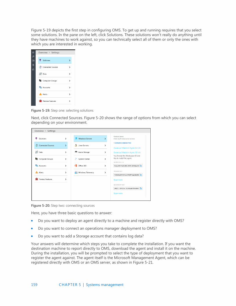
159 CHAPTER 5 | Systems management
Figure 5-19 depicts the first step in configuring OMS. To get up and running requires that you select
some solutions. In the pane on the left, click Solutions. These solutions won’t really do anything until
they have machines to work against, so you can technically select all of them or only the ones with
which you are interested in working.
Figure 5-19: Step one: selecting solutions
Next, click Connected Sources. Figure 5-20 shows the range of options from which you can select
depending on your environment.
Figure 5-20: Step two: connecting sources
Here, you have three basic questions to answer:
Do you want to deploy an agent directly to a machine and register directly with OMS?
Do you want to connect an operations manager deployment to OMS?
Do you want to add a Storage account that contains log data?
Your answers will determine which steps you take to complete the installation. If you want the
destination machine to report directly to OMS, download the agent and install it on the machine.
During the installation, you will be prompted to select the type of deployment that you want to
register the agent against. The agent itself is the Microsoft Management Agent, which can be
registered directly with OMS or an OMS server, as shown in Figure 5-21.
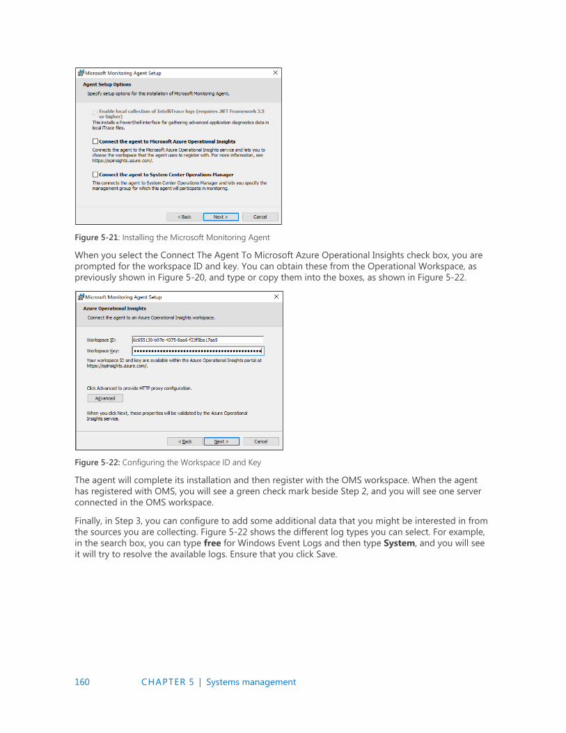
160 CHAPTER 5 | Systems management
Figure 5-21: Installing the Microsoft Monitoring Agent
When you select the Connect The Agent To Microsoft Azure Operational Insights check box, you are
prompted for the workspace ID and key. You can obtain these from the Operational Workspace, as
previously shown in Figure 5-20, and type or copy them into the boxes, as shown in Figure 5-22.
Figure 5-22: Configuring the Workspace ID and Key
The agent will complete its installation and then register with the OMS workspace. When the agent
has registered with OMS, you will see a green check mark beside Step 2, and you will see one server
connected in the OMS workspace.
Finally, in Step 3, you can configure to add some additional data that you might be interested in from
the sources you are collecting. Figure 5-22 shows the different log types you can select. For example,
in the search box, you can type free for Windows Event Logs and then type System, and you will see
it will try to resolve the available logs. Ensure that you click Save.

161 CHAPTER 5 | Systems management
Figure 5-23: Adding logs
From here the rules are downloaded to the agent, as normal, and processed. Data will be uploaded to
the portal and assessed. The main solution gallery will be updated with the latest information pulled
from the system. You can add additional solutions from the solutions gallery when you need them.
Figure 5-24 presents an updated dashboard after information has been uploaded.
Figure 5-24: Updated dashboard
You can click each site to view more information. From here you can also configure additional items
such as Automation, Backup, and Azure Site Recovery. You can use all three areas in hybrid scenarios
to manage cloud resources and on-premises resources from the cloud.
From here, you can explore Log Search and all additional solutions, as shown in Figure 5-25.
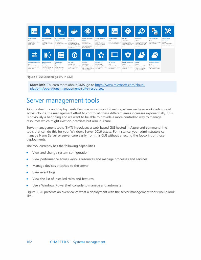
162 CHAPTER 5 | Systems management
Figure 5-25: Solution gallery in OMS
More info To learn more about OMS, go to https://www.microsoft.com/cloud-platform/operations-management-suite-resources.
Server management tools
As infrastructure and deployments become more hybrid in nature, where we have workloads spread
across clouds, the management effort to control all these different areas increases exponentially. This
is obviously a bad thing and we want to be able to provide a more controlled way to manage
resources which might exist on-premises but also in Azure.
Server management tools (SMT) introduces a web-based GUI hosted in Azure and command-line
tools that can do this for your Windows Server 2016 estate. For instance, your administrators can
manage Nano Server or server core easily from this GUI without affecting the footprint of those
deployments.
The tool currently has the following capabilities
View and change system configuration
View performance across various resources and manage processes and services
Manage devices attached to the server
View event logs
View the list of installed roles and features
Use a Windows PowerShell console to manage and automate
Figure 5-26 presents an overview of what a deployment with the server management tools would look
like.

163 CHAPTER 5 | Systems management
Figure 5-26: Sample deployment for server management tools
You will also observe from the diagram that a gateway server (in the middle of the diagram) is
required to allow on-premises infrastructure to communicate with the service in Azure.
SMT support for Windows 2012 and later
If this is a Windows 2016 Server, no prerequisite work is required, but if you are using a previous
edition of Windows (i.e., 2012 or 2012 R2) you must install WMF 5.0 so that you can manage Windows
Server 2016 hosts, including Nano Server.
With the exception of Windows Update and Device Manager, all SMT tools will work with Windows
2012 and 2012 R2. There is one thing to consider when approaching SMT and using it to manage your
previous versions of Windows: the dependencies of installed applications on the server. For example,
will your application break if you install a newer version of WMF?
Note To verify if you can install WMF 5.0 before proceeding to connect the server to SMT go to https://msdn.microsoft.com/en-us/powershell/wmf/5.0/productincompat.
You might also need to perform additional tests to ensure that your applications perform correctly
with WMF 5.0.
Persistent credentials
In Windows Server 2016 Server Management Tools, you can store credentials encrypted by using
AES256 encryption and stored in Azure. The gateway is responsible for encrypting these credentials
with a certificate that only exists on the gateway before uploading the credentials to Azure in a
secured state. These credentials can then be decrypted only by the gateway using the certificate that
encrypted the credentials in the first place. The certificate, as stated, never leaves the gateway and
only ever exists on the gateway.
Firewall rules
Centrally managing a Windows firewall provides numerous benefits to servers by ensuring that a
standardized policy is enforced. Unfortunately, dealing with a Windows firewall outside of traditional
enterprise monitoring tools typically has been a difficult task; you can’t easily work at scale and it can

164 CHAPTER 5 | Systems management
be difficult to gather a complete understanding what rules are turned on and what their status is. In
SMT, Microsoft provides GUI support for looking at the firewall rules on a specific machine, making it
easier to understand what is happening, as demonstrated in Figure 5-27.
Figure 5-27: Firewall Rules in SMT
Windows PowerShell script editor enhancements
The Windows PowerShell script editor in SMT has been upgraded to support file-browsing capabilities
on a machine. Now, you can open, edit, and save scripts on specified machines.
The script editor also has the ability to connect directly to an Azure Storage Blob (see Figure 5-28) and
save your scripts to it. The scripts then become accessible to all servers in your subscription and
beyond!
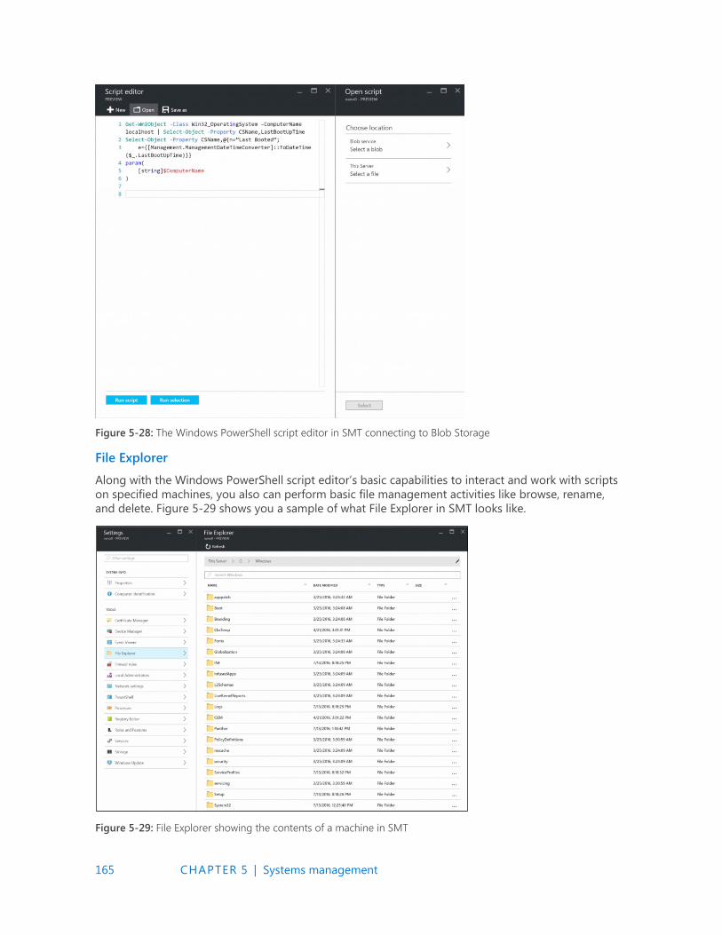
165 CHAPTER 5 | Systems management
Figure 5-28: The Windows PowerShell script editor in SMT connecting to Blob Storage
File Explorer
Along with the Windows PowerShell script editor’s basic capabilities to interact and work with scripts
on specified machines, you also can perform basic file management activities like browse, rename,
and delete. Figure 5-29 shows you a sample of what File Explorer in SMT looks like.
Figure 5-29: File Explorer showing the contents of a machine in SMT
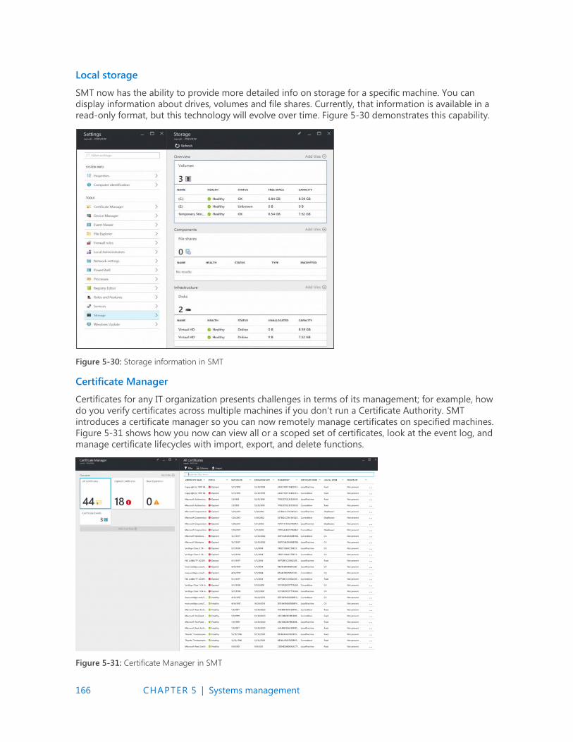
166 CHAPTER 5 | Systems management
Local storage
SMT now has the ability to provide more detailed info on storage for a specific machine. You can
display information about drives, volumes and file shares. Currently, that information is available in a
read-only format, but this technology will evolve over time. Figure 5-30 demonstrates this capability.
Figure 5-30: Storage information in SMT
Certificate Manager
Certificates for any IT organization presents challenges in terms of its management; for example, how
do you verify certificates across multiple machines if you don’t run a Certificate Authority. SMT
introduces a certificate manager so you can now remotely manage certificates on specified machines.
Figure 5-31 shows how you now can view all or a scoped set of certificates, look at the event log, and
manage certificate lifecycles with import, export, and delete functions.
Figure 5-31: Certificate Manager in SMT
167 CHAPTER 5 | Systems management
Deployment
Deployment of SMT is relatively straightforward; however, it does involve the use of Azure and will
require an Azure subscription. There are various ways of obtaining an Azure subscription but the
simplest is to go to https://azure.microsoft.com/free/. Here, you can create a subscription if your
organization does not already have one.
The gateway server you will create also needs Internet access, so it will need to be on a routable
subnet within your organization.
There are two methods to deploy SMT: via the Azure Portal or Windows PowerShell. For the
GUI deployment you can go to https://blogs.technet.microsoft.com/servermanagement/
2016/08/17/deploy-setup-server-management-tools/. To use Windows PowerShell, go to
http://social.technet.microsoft.com/wiki/contents/articles/35196.microsoft-azure-managing-nano-
server-with-server-management-tools.aspx.
More info For all the latest information on SMT, read the product group’s blog at https://blogs.technet.microsoft.com/servermanagement/.
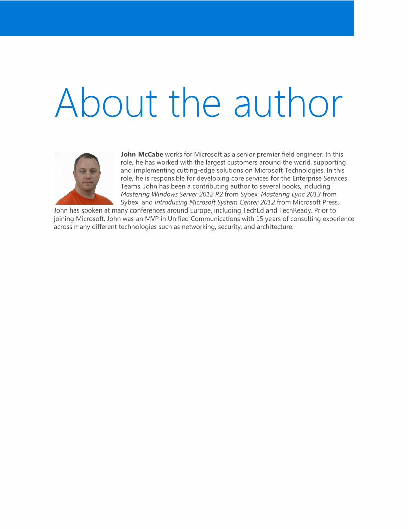
About the author John McCabe works for Microsoft as a senior premier field engineer. In this
role, he has worked with the largest customers around the world, supporting
and implementing cutting-edge solutions on Microsoft Technologies. In this
role, he is responsible for developing core services for the Enterprise Services
Teams. John has been a contributing author to several books, including
Mastering Windows Server 2012 R2 from Sybex, Mastering Lync 2013 from
Sybex, and Introducing Microsoft System Center 2012 from Microsoft Press.
John has spoken at many conferences around Europe, including TechEd and TechReady. Prior to
joining Microsoft, John was an MVP in Unified Communications with 15 years of consulting experience
across many different technologies such as networking, security, and architecture.
Microsoft Press
Free ebooks
From technical overviews to drilldowns on special topics, get free ebooks from Microsoft Press at: www.microsoftvirtualacademy.com/ebooks Download your free ebooks in PDF, EPUB, and/or Mobi for Kindle formats. Look for other great resources at Microsoft Virtual Academy, where you can learn new skills and help advance your career with free Microsoft training delivered by experts.