Embed Size (px)
Citation preview

Paper ID #11460
Introducing Kinematics with Robot Operating System (ROS)
Dr. Asad Yousuf, Savannah State UniversityMr. William Lehman, Bill’s Robotic Solution
William Lehman is President of Bill’s Robotic Solutions which he started in July of 2013. He has hadover twenty years of experience in software and hardware development. He has worked on numerousprojects in digital communication systems, robotics, and aerospace applications. Mr. Lehman receivedhis Bachelor of Science degree in Electrical Engineering in 1979 from Catholic University of America.
Dr. Mohamad A. Mustafa, Savannah State UniversityDr. Mir M Hayder, Savannah State University
Dr. Hayder is an Assistant Professor in the Department of Engineering Technology at savannah StateUniversity, GA. He received PhD in Mechanical Engineering from McGill University, Canada in 2009.His research interest lies in the areas of fluid-structure interaction, flow-induced vibrations, syngas andblended fuel combustion, nanofluids, concentrating solar power technologies, and flow and structuralsimulations.
c©American Society for Engineering Education, 2015
Page 26.1024.1

Introducing Kinematics with Robot Operating System (ROS)
Abstract
The study of Kinematics is essential to Robotics. A robot, to perform most applications needs to
process positional data and transform data from one frame of reference to another. Robots have
sensors, links and actuators each with its own frame of reference, so transformations between
reference frames can be quite tedious. Traditionally Kinematics for robots is introduced to
students with MatLab and the Robotic Toolbox. In this paper we examine the introduction of
Kinematics for robotics with the features and tools available in the open source Robot Operating
System (ROS). ROS implements tools for Kinematics transforms (tf) as a key part of the ROS
Core Libraries. ROS defines robots with the Unified Robot Description Format (URDF) standard
based upon Extensible Markup Language (XML). URDF is in many respects similar to Denavit-
Hartenberg (D-H) Convention, but with significant additional enhancements.
We choose to introduce the Electronic Engineering Technology (EET) students to Kinematics
and ROS so they would have greater insight into engineering projects involving robotics. We
also found that using ROS in robotics projects not only makes the projects more interesting to
students but, gives students an authentic experience with distributive systems and odometry
sensors. Kinematics for robots uses Linear Algebra, Matrices, Natural logarithms (Euler’s
equation), Imaginary numbers and Trigonometry. The areas of mathematics we used to introduce
kinematics for robotics to EET students are very similar to the mathematics to understand
electricity, electric fields and circuit theory. We emphasize matrix operations, operations
involving Triaminic functions and imaginary numbers. This paper summarizes the result of this
approach.
Introduction
The study and understanding of Kinematics is a tool in both industrial and mobile Robotics. A
robot, to perform most applications needs to process positional data and transform data from one
frame of reference to another. Robots have sensors, links and actuators each with its own frame
of reference, so transformations between reference frames can be quite tedious. Software makes
transforms easy to perform and automatic, but the student needs to understand Kinematics to use
the software [1].
We designed the labs for EET students to give them basic kinematic concepts while gaining
experience with ROS. We have added additional material for advanced students interested in
robotics. In this paper we present enough kinematic theory to give the reader a good idea of
what kinematic concepts are presented in the lab. In the detailed descriptions of the labs we also Page 26.1024.2

covered how we used ROS to learn kinematics. The pre-lab materials and labs are available as
free open source for readers who wish to know more.
The topics covered for the Kinematic Labs are depicted in Figure 1. Euler angles tend to be
intuitive to describe robot motion but have issues when angles approach 90. Quaternions are an
alternative to using Euler angles but are not intuitive to use. We will treat Quaternions as black
boxes and use Euler angles for our inputs to the robot model to have the best of both descriptions
of rotation [2].
Joints used in our labs were Revolute or Prismatic. We can approximate other joint types in
ROS using combinations of Revolute and Prismatic joints. We limited our joint types to keep
the introduction to kinematics simple.
Joints in robots are usually combined in a series to form chains. Our Robot modeling software
allows for chains to also be combined into tree like structures. A good example of a Kinematic
tree would be a robot with two or more arms.
Forward Kinematics determines the position of the Robot given the joint rotations or distance for
Prismatic sliding joints. Inverse Kinematics is more difficult than Forward Kinematics since we
need to find one or more ways to move a Robot to a given point in space. Where there is usually
a solution in Forward Kinematic problems there may be multiple or no solutions in an Inverse
Kinematic problem.
Figure 1 Robotic Kinematic Topic’s for Labs
Robotic Operating System
We will explore Kinematics using software packages. ROS has a number of software packages
that deal with Kinematics (see Figure 2). To demonstrate the Kinematic concepts from Figure 1,
we needed to use more than one software package from Figure 2. RVIZ is a robot simulator that
Robotic Kinematics
Prismatic and
Revolute Joints
Euler Angles
Kinematic Chains and
Trees
Quaternions
URDF & D-H
Inverse Kinematics
Page 26.1024.3

can display a URDF robot model in 3D along with data from other sensors such as cameras. All
the labs take advantage of RVIZ to demonstrate the six Kinematic concepts in Figure 1.
The tf software package provides a library of Kinematic routines that provides all the
mathematical functions we need to transform Kinematic data from one frame of reference to
another in our robot manipulators.
Transforms in ROS are made on positional data in both space and time. There are good tutorials
in ROS on how data is transformed in the temporal domain. In this paper, we use examples and
labs where the positional data is constant so we can ignore extrapolation in time. Time is
important but we ignore it to “keep it simple” for students [3]. URDF is a XML modeling
language capable of modeling most robots. Python is a programming language with interfaces to
the ROS system.
Software packages in ROS are written mainly in Python, Lisp and C++. We will use Python
interpreter much like a calculator. RVIZ GUI will display robot information and we will confirm
the results using calculations made in Python.
Figure 2 – Software Packages in ROS for Lab
MOVEIT is a fascinating software package for controlling robot arms and manipulator’s.
Each of the labs developed to introduce students to Robot Kinematics is listed in Table 1.
Lab Title
1 RVIZ and PYTHON with Simple Robot Manipulator Model
2 RVIZ, TF and PYTHON with Aircraft Robot Model
3 URDF and Hydra Robot Models
3
EXTENT
Converting D-H Table to URDF Model
4 MOVEIT and Inverse Kinematics
Table 1 – Titles of Labs
Lab 1 deals with analyzing views of robot from different Frames of Reference and converting
Quaternions to and from axis angle representation.
ROS
RVIZ
tf
URDFPython
Moveit
Page 26.1024.4

In Lab 2 the student converts Quaternions to and from Euler angles using the Python
Programming Language.
In Lab3 students learn to read and write URDF files with the Linux Ubuntu screen editor gedit.
The extension to Lab 3 exposes students to converting D-H tables to URDF files. Finally,
students confirm there URDF model is correct with the RVIZ robot simulator.
Lab 4 gives the opportunity to run a number of inverse algorithms from OMPL using both the
Willow Garage PR2 and 6R robot [4].
Please note Labs 1 – 3 deals with concepts in Forward Kinematics and Labs 4 in Inverse
Kinematics.
Lab 1 RVIZ and PYTHON with Simple Robot Manipulator Model
In this Lab we will learn how to use the RVIZ Robot Simulator and convert Quaternions to/from
axis angle representation. We will use the Python programming language to make our manual
calculations and confirm ROS is working as expected (see Figure 1). Python is an interpreted
language and supported by the Robotic Operation System (ROS).
Figure 3 – Lab Setup
There are four sections to this lab:
a) Setup and RVIZ features
b) Converting from Quaternion to Axis Angle Representation
c) Frames of Reference
d) Robot Arm Movement Sequence
Setup will guide you through startup of RVIZ, Robot State Publisher and terminals. Features of
the RVIZ display will be explored. We will convert Quaternions to Axis Angle representation to
get useful information from the Quaternion. We will also change the Frames of Reference in the
chain of links to take different measurements. Finally we will explore Sequences of moving arm
joints to set the robot to different positions in 3D space.
ROS Python and tf
Page 26.1024.5

Next is a screen shot of the RVIZ Robot Simulator showing the robot arm. The position is shown
on the RVIZ screen along with relative position using Quaternions for the orientation. The
Robot State Publisher screen is also displayed with sliders to control the robot arm [5].
Figure 4 RVIZ Simulator and State Publisher Window
The second screen shot of the RVIS Robot Simulator shows the robot arm visuals turned off to
reveal the axis systems of each frame.
Figure 5 Joint Conventions and 3D Axis
Quaterions
Axis angle is somewhat intuitive and similar to Quaternions but in 3D. Axis angle can be
converted to/from Euler angles to and from Quaternions. Eq. 20 through Eq. 30 converts the
axis angle vector to a Quaternion [6].
𝑞1 = sin (𝛼
2) cos( 𝛽𝑥) (Eq. 1)
𝑞2 = sin (𝛼
2) cos( 𝛽𝑦) (Eq. 2)
𝑞3 = sin (𝛼
2) cos( 𝛽𝑧) (Eq. 3)
Page 26.1024.6

𝑞4 = cos (𝛼
2) (Eq. 4)
The Quaternion is normalized so equation Eq. 5 is applies.
𝑞12 + 𝑞22 + 𝑞32 + 𝑞42 = 1 (Eq. 5)
Equations 6 through 9 convert a Quaternion to axis angle vector.
= 2 cos−1(𝑞4) (Eq. 6)
𝑥 = 𝑞1
√1−𝑞42 (Eq. 7)
𝑦 = 𝑞2
√1−𝑞42 (Eq. 8)
𝑧 = 𝑞3
√1−𝑞42 (Eq. 9)
The direction cosine angles can be found with the following equations:
𝑥
= cos−1 𝑥 (Eq. 10)
𝑦
= cos−1 𝑦 (Eq. 11)
𝑧
= cos−1 𝑧 (Eq. 12)
EXAMPLE
Given the Quaternion:
q1 = 0.293802, q2 = -0.0957684, q3 = -0.294745 , q4 = 0.904231
Note the Quaternion is normalized:
1 = 𝑞12 + 𝑞22 + 𝑞32 + 𝑞42 = 0.999999518
a = 0.427043673
= 2 cos−1(𝑞4) = 0.8824416 = 50.56
𝑥 = 0.6829905, 𝑦 = -0.2242590, 𝑧 = -0.6901987
Note that 𝑥2 + 𝑦2 + 𝑧2 = 1 and is thus normalized.
𝑥
= cos−1 𝑥 = 46.5
Page 26.1024.7

𝑦
= cos−1 𝑦 = 77.4
𝑧
= cos−1 𝑧 = 133.6
Lab 2 RVIZ, TF and PYTHON with Aircraft Robot Model
In this Lab we will learn how to use the RVIZ Robot Simulator, Python Programming Interpreter
and ROS tf library to study Euler angles. The Robot State Publisher allows for the Robot model
in RVIZ to be controlled with sliders.
Figure 6 – Lab Setup
There are three sections to this lab:
a) Euler Angles and Gimbal Lock
b) Converting Quaterions to/from Euler Angles
c) Frames of Reference and the tf Transform
Euler angles are expressed in terms of roll, pitch and yaw to specify the orientation of an aircraft.
In ROS roll is a rotation about the x axis, pitch is a rotation about the y axis and yaw is a rotation
about the z axis. All rotations in ROS follow the Right Hand Rule for direction of rotation [7].
ROLL PITCH YAW
Figure 7 Roll, pitch and yaw of aircraft
Euler Angle Rotation Combinations
RVIZ & Robot State Publisher
Python and tf
Page 26.1024.8

Proper Euler
Angles
Tait-Bray
Angles
RYR RYP
RPR RPY
PRP PRY
PYP PYR
YPY YPR
YRY YRP
Table 2 Euler Angle Combinations
Table 2 shows the combinations of Euler angles possible. Note, that Tait-Bray angles are also
referred to as Euler angles.
The tf library provides two ways to convert Euler angles to Quaternions with any of the
combinations in Table 2. The tf library can also provide a convenient conversion from
Quaternions to Euler angles [8].
Euler angles are intuitive to use except there are issues with Gimbal Lock. Quaternions avoid the
issues of Euler angles, but are difficult to visualize. We solve this dilemma by converting to and
from Euler angles [9].
Using multiple Frames of Reference for a Robot makes it easy to calculate angles and distances
from one point in the environment to another. We use the tf library in ROS to perform this task.
We also learn some of the underlying concepts behind the magic of tf Transforms.
Lab 3 URDF and Hydra Robot Models
In this Lab we will learn how Unified Robot Description Format (URDF) describes robots and
use it to design our own Robot. We will use the Ubuntu Linux editor gedit to modify and create
URDF text files. We will use RVIZ a Robot Simulator and the Robot State Publisher in ROS to
display and control our Robot Models [10].
There are five sections to this lab:
a) URDF format and Simple Robot Model
b) Ubuntu Linux Graphical Screen Editor gedit
c) Hydra Robot Example
d) Hydra Robots URDF models
e) Design a Robot URDF model
Page 26.1024.9

URDF can be used to model a robot with links (members) connected by joints in a chain or tree.
Most Industrial Robots can be modeled by chains of joints offset by links. Multi-arm robots can
be modeled with a tree data structure of joints connected by links to a base link. We do not
cover the transmission element at this point since all the robots we need are created by chains or
trees. Other elements of URDF such as sensors are also not used.
There are two main types of URDF XML elements we need to create our robots links and joints.
Link elements (or blocks) can contain elements for inertial properties, visual properties, and
collision properties. Joint elements can also contain elements for origin, parent link name, child
link name, axis of rotation/translation, calibration, dynamics, limit, mimic another joint and
safety controller information.
Figure 8 Kinematic Tree
The Kinematic Chain or Tree can be represented by a graph of links connected though joints
between each Link and other links.
Link 1A is moved by the joint between the Base Link and Link 1A. Link 1A is connected to a
joint between Link 1A and Link 2A that moves Link 2A. Link 1A is also connected to a joint
between Link 1A and Link 3A which moves Link 3A. Each Link is moved by a single joint but
may be connected to a number of joints that move other links. In URDF terminology multiple
joints can be connected to one link, but the link can only be a Child in one of the joints
connected to it and must be a Parent to all the other joints connected to it.
The Base Link is the first link in the tree and is special. The origin of the axis system to World
coordinates x, y and z is determined from the Odometry Frame (/odom) and Map. In the
example to follow our robot arm axis origin is located at World Coordinate 0,0,0.
It should be noted the students can get a graph of the Kinematic Tree or Chain with
urdf_graphviz command typed in the terminal [11].
Link elements must have the “name” attributes for the link. The inertial and collision properties
for the link are not included, except where it will be connected to a prismatic type joint. The
visual information can be provided by specifying a rectangle, sphere or cylinder shape for the
link or a mesh. Although the mesh produced by a Computer Aided Design (CAD) program can
be very pleasing to the eye, we keep it simple with a rectangle or cylinder shape. As a
Base Link
Link 1A
Link 2A Link 3A
Link 1B
Link 2B
Page 26.1024.10

convention in the design of our robots for the labs we group together all the link elements to and
then all the joint elements for readability of the URDF file [12].
Figure 9 Types of URDF XML Blocks
The joint element has a name and an attribute for the type of joint. We only select a revolute,
continuous or prismatic type for the joint. The ROS Continuous joint type in actuality is a
revolute. In URDF a continuous joint is a revolute joint where the angle of rotation is 360,
where the revolute joint limits of rotation must be specified. The joint attaches a parent link to a
child link. The child link can be a parent link to one or more other links in a chain or tree. The
child link however can never be connected through a series of joints and links back to its parent
link making a loop [13].
An example link element can be found in figure 10. We could have named the link anything we
felt useful to identify it, since it was the second link in the chain we named it “link2”. We skip
the inertial and collision information, not because it’s not useful but to keep the example simple.
The visual element contains the geometry element which sets the type of display using the
geometry element. The box element is inside the geometry element. The box element sets the x,
y, z sizes of the rectangle. The visual also contains the material element which sets the color of
the rectangle link. We set it to an arbitrary color to distinguish this link from other links in the
RVIS simulator display.
ROBOT NAME
Link Elements 1-N
Joint Elements 1-N
END ROBOT
Page 26.1024.11
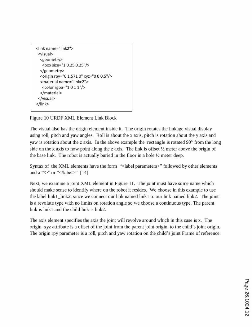
Figure 10 URDF XML Element Link Block
The visual also has the origin element inside it. The origin rotates the linkage visual display
using roll, pitch and yaw angles. Roll is about the x axis, pitch is rotation about the y axis and
yaw is rotation about the z axis. In the above example the rectangle is rotated 90 from the long
side on the x axis to now point along the z axis. The link is offset ½ meter above the origin of
the base link. The robot is actually buried in the floor in a hole ½ meter deep.
Syntax of the XML elements have the form “<label parameters>” followed by other elements
and a “/>” or “</label>” [14].
Next, we examine a joint XML element in Figure 11. The joint must have some name which
should make sense to identify where on the robot it resides. We choose in this example to use
the label link1_link2, since we connect our link named link1 to our link named link2. The joint
is a revolute type with no limits on rotation angle so we choose a continuous type. The parent
link is link1 and the child link is link2.
The axis element specifies the axis the joint will revolve around which in this case is x. The
origin xyz attribute is a offset of the joint from the parent joint origin to the child’s joint origin.
The origin rpy parameter is a roll, pitch and yaw rotation on the child’s joint Frame of reference.
<link name="link2"> <visual> <geometry> <box size="1 0.25 0.25"/> </geometry> <origin rpy="0 1.571 0" xyz="0 0 0.5"/> <material name="linkc2"> <color rgba="1 0 1 1"/> </material> </visual> </link>
Page 26.1024.12

Figure 11 URDF XML Joint Element Example
The following command in the terminal window can be used in ROS to check the syntax of the
URDF file:
rosrun urdfdom check_urdf filename.urdf
Our robot URDF examples with prismatic joints are slightly more complex since prismatic joints
require limits parameters and safety parameters not required for continuous joint type.
Lab 3 Extension – Converting D-H Table to URDF Model
Denivit-Hartenberg (D-H) Conventions ease the process of calculating the position and orientation
of Frames in a Kinematic Chain [15]. As seen in the last section URDF can be used to model
Robots that are Kinematic Trees. URDF does not require axis systems for Frames to only rotate
about the Z axis. URDF actually uses arbitrary axis for Revolute or Prismatic Joints. However,
we can tabulate the parameters of our URDF joint variables in a table analogous to D-H
parameters.
To demonstrate we will use the axis system in Figure 12 to make the D-H table for the 3R robot
similar to the 3R robot we saw earlier. The Ɵ variable represents rotation about the z axis of the
joint. The d parameter is the distance along the z axis to the next joint. The d is a variable in the
case of Prismatic joints. The a parameter is the distance of each common normal or the offset
between joints. Finally the parameter is the angle between the current joint i and the next joint
i+1. The parameters in the D-H table can be translated to parameters in the URDF Joint element
[16].
<joint name="link1_link2" type="continuous"> <parent link="link1"/> <child link="link2"/> <axis xyz="1 0 0" /> <origin rpy="0 0 0" xyz="0 0 1.0"/> </joint>
Page 26.1024.13

Figure 12 Axis 3R Robot
Note in Figure 12 has the y axis into the page for Joint 1 and z axis out of the page for Joint 2 and
3.
Link Ɵ𝑖 𝑑𝑖 𝑎𝑖 𝑖
1 Ɵ1 𝑑1 0 90
2 Ɵ2 0 𝑎2 0
3 Ɵ3 0 𝑎3 0
Table 3 D-H Parameters for 3R Robot
The parameters of the URDF Joint Elements can be enumerated in a Table similar in concept to
the D-H table. For a simple Kinematic Chain there would be a single corresponding table to model
the joints in the Robot. For a Kinematic Tree we could use multiple Joint Element Parameter
tables to represent each Kinematic Chain in the Tree.
The 𝑑𝑖 parameters will always be placed in the corresponding Joint + 1 z axis offset between Joint
i and Joint i+1. The 𝑎𝑖 parameter is the offset between Joint i and Joint i+1 along the x axis of
Joint I and joint i+1.
We have to place the robot in World coordinates in ROS, so we will select a convenient orientation
and origin to simplify calculations. We put the 3R robot at the origin of the World axis system
and aligned with that axis system. This means instead of rotating Joint 2 by 90 we will rotate
Joint 2 so the z axis will be out of the page. Joint 3 and 4 will also be rotated since 2 is attached to
3 and 3 is attached to Joint 4. Joint 4 is a Fixed type Joint and does not move. Joint 4 is included
to show a3 parameter in the D-H table.
Page 26.1024.14

# Joint
Type
Joint
Link #
Joint+1
Link #
x y z Joint+1
Roll
Joint+1
Pitch
Joint+1
Yaw
Joint+1
Axis X
Joint+1
Axis y
Joint+1
Axis z
1 R Base 1 0 0 𝑑1 0 0 0 0 0 1
2 R 1 2 𝑎2 0 0 90 0 0 0 0 1
3 R 2 3 𝑎3 0 0 0 0 0 0 0 1
4 Fixed 3 4 0 0 0 0 0 0 - - -
Table 4 URDF Joint Element Parameters
Dummy URDF Link elements are set up with simple names such as Link_1, Link_2 etc. No
information is needed in the URDF Link Element since we are not displaying visual elements of
the Robot model in the Lab. We need a Base Link not included in D-H table to attach our robot
model to the World Coordinates.
The parameters from the table to the URDF Joint Element are also straight forward. The x,y,z
parameters corresponds to the origin xyz parameter in the URDF Joint element. The roll, pitch
and yaw parameters corresponds to the origin rpy parameter in the URDF Joint element. Finally
the axis parameters define a unit vector pointing along the z axis. Since this is a Revolute joint,
the joint will rotate around the z axis.
Figure 13 D-H 3R Robot Displayed in RVIZ
After students create the URDF Joint Element Parameter given the D-H table they perform, they
convert it to URDF and display the results in RVIZ to confirm it matches the Fig. 12 axis system
Page 26.1024.15
orientation. The a3 parameter is between Joint 3 and Joint 4. The Red axis is x, the Green axis is
y and the Blue axis is z in Fig. 13.
Lab 4 MOVEIT and Inverse Kinematics
There are two sections to this lab:
a) Setup Moveit
b) Using Different Planning Algorithms to move robot
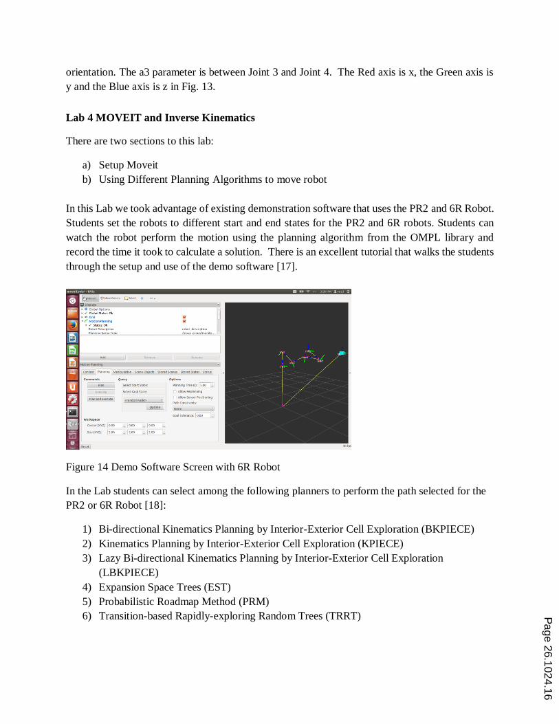
In this Lab we took advantage of existing demonstration software that uses the PR2 and 6R Robot.
Students set the robots to different start and end states for the PR2 and 6R robots. Students can
watch the robot perform the motion using the planning algorithm from the OMPL library and
record the time it took to calculate a solution. There is an excellent tutorial that walks the students
through the setup and use of the demo software [17].
Figure 14 Demo Software Screen with 6R Robot
In the Lab students can select among the following planners to perform the path selected for the
PR2 or 6R Robot [18]:
1) Bi-directional Kinematics Planning by Interior-Exterior Cell Exploration (BKPIECE)
2) Kinematics Planning by Interior-Exterior Cell Exploration (KPIECE)
3) Lazy Bi-directional Kinematics Planning by Interior-Exterior Cell Exploration
(LBKPIECE)
4) Expansion Space Trees (EST)
5) Probabilistic Roadmap Method (PRM)
6) Transition-based Rapidly-exploring Random Trees (TRRT) Page 26.1024.16

Building upon the RVIZ Plugin tutorial the student is presented with a problem requiring
building a table for the selected algorithm using different Planning Groups and other Planning
parameters. The student then records the results of the test in a table of planning parameters vs
time and evaluate the results. The goal of the Lab is to give them some insight into the
complexity of Inverse Kinematics.
Conclusion
We have presented the major features of the five labs developed to introduce our students to
Kinematics using ROS. We are developing labs where students use accelerometers, and gyros to
track real robots using ROS. The Introduction to Robotic Kinematics should provide the
background to understanding Kinematic aspects of these labs.
The Robot Toolbox provides a powerful system for introducing students to Robotic Kinematics
[19]. However for EET students teaching kinematics on ROS is more efficient, since students use
ROS on other projects.
Information to obtain the free Open Source labs outlined in this paper can be found at reference
[20].
References
[1] Foote Tully, “Technologies for Practical Robot Applications (TePRA), 2013 IEEE International Conference on
Open-Source Software workshop in Proceedings 6556373 tf: The transform library”, April 2013, Pages 1-6. Doi
10.1109/TePRA.2013.6556373, ISSN 2325-0526
[2] Diebel James, “Representing Attitude: Euler Angles, Unit Quaternions, and Rotation Vectors”, Stanford,
California 94301–9010 “, 20 October 2006 from http://www.astro.rug.nl/software/kapteyn/_downloads/attitude.pdf
[3] www.wiki.ros.org/tf
[4] “ Open Motion Planning Library: A Primer”, http://ompl.kavrakilab.org
[5] Siciliano Bruno, Khatib Oussama , “Handbook of Robotics” , DIGITAL DESIGN page 11
[6] www.euclideanspace.com/maths/geometry/rotations/conversions/
[7] “Coordinate Frames for Mobile Platforms”, http://www.ros.org/reps/rep-0105.html
[8] “Standard Units Measure and Coordinate Conventions”, http://www.ros.org/reps/rep-0103.html Section 2.5
Visualization wiki.ros.org/urdf
Page 26.1024.17

[9] wiki.ros.org/geometry/CoordinateFrameConventions
[10] http://wiki.ros.org/urdf/Tutorials
[11] “5.2 Visualization”, wiki.ros.org/urdfoveit.ros.org/urdf
[12] wiki.ros.org/urdf/XML/link
[13] wiki.ros.org/urdf/XML/joint
[14] en.wikipedia.org/wiki/XML
[15] Mark W. Spong, Seth Hutchinson, and M. Vidyasagar, “Robot Dynamics and Control Second Edition”, Chapter
3 Forward Kinematics: The Denivit-Hartenberg Convention”, Jan 28, 2004
[16] Thomas Federico , “Universitat Politecnica DE Catalunya BarcelonaTECH Solved Problems in Robot
Kinematics Using the Robotic Toolbox”, [email protected] April 2, 2012
[17] http://moveit.ros.org/documentation/tutorials/
[18] Ioan, A. Sucan, Member, IEEE, Mark Moll, Member, IEEE, and Lydia E. Kavraki, Senior Member, IEEE ]
“The Open Motion Planning Library”,http://ompl.kavrakilab.org/ieee-ram-2012-ompl.pdf
[19] Corke Peter, “Robotic Toolbox for Matlab Release 9”, Release 9.9”, April 2014,
http://www.petercorke.com/robot
[20] http://www.brazenbot.com
Page 26.1024.18