Embed Size (px)
Citation preview
1
Tech. Talk with Rick Alves
Introduction to Troubleshooting
Topics to be Covered:
Troubleshooting
Contact Phone numbersTool recommendationsProgramming methodsBatteries & Care of Batteries
Field Load TestsChargers
Helpful Tools & Support: Invacare
•Invacare Technical Support: 1-800-668-5324 ext. 2655
Please have ready the model number, serial number, controller software version & any error codes.Always check that the batteries before calling.
•The Aftermarket Group/TAG: 1-800-668-5324
www.invacare.ca
2
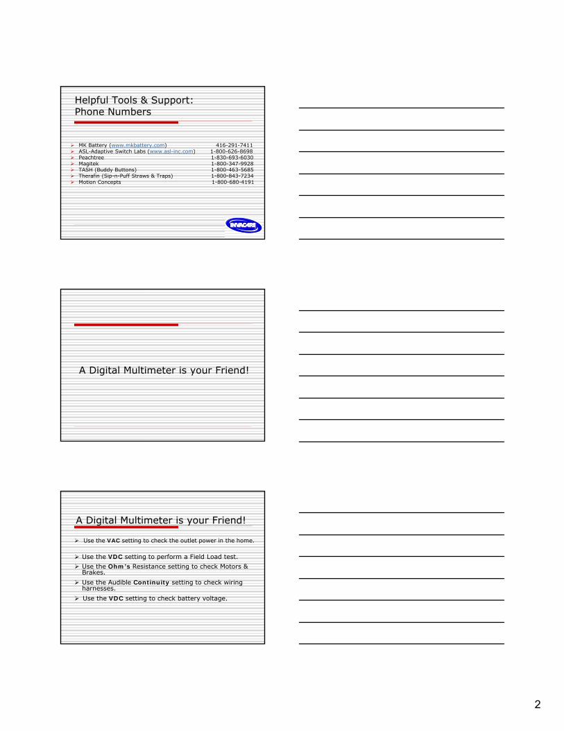
MK Battery (www.mkbattery.com) 416-291-7411 ASL-Adaptive Switch Labs (www.asl-inc.com) 1-800-626-8698 Peachtree 1-830-693-6030 Magitek 1-800-347-9928 TASH (Buddy Buttons) 1-800-463-5685 Therafin (Sip-n-Puff Straws & Traps) 1-800-843-7234 Motion Concepts 1-800-680-4191
Helpful Tools & Support:Phone Numbers
A Digital Multimeter is your Friend!
A Digital Multimeter is your Friend!
Use the VAC setting to check the outlet power in the home.
Use the VDC setting to perform a Field Load test. Use the Ohm’s Resistance setting to check Motors &
Brakes. Use the Audible Continuity setting to check wiring
harnesses. Use the VDC setting to check battery voltage.

3
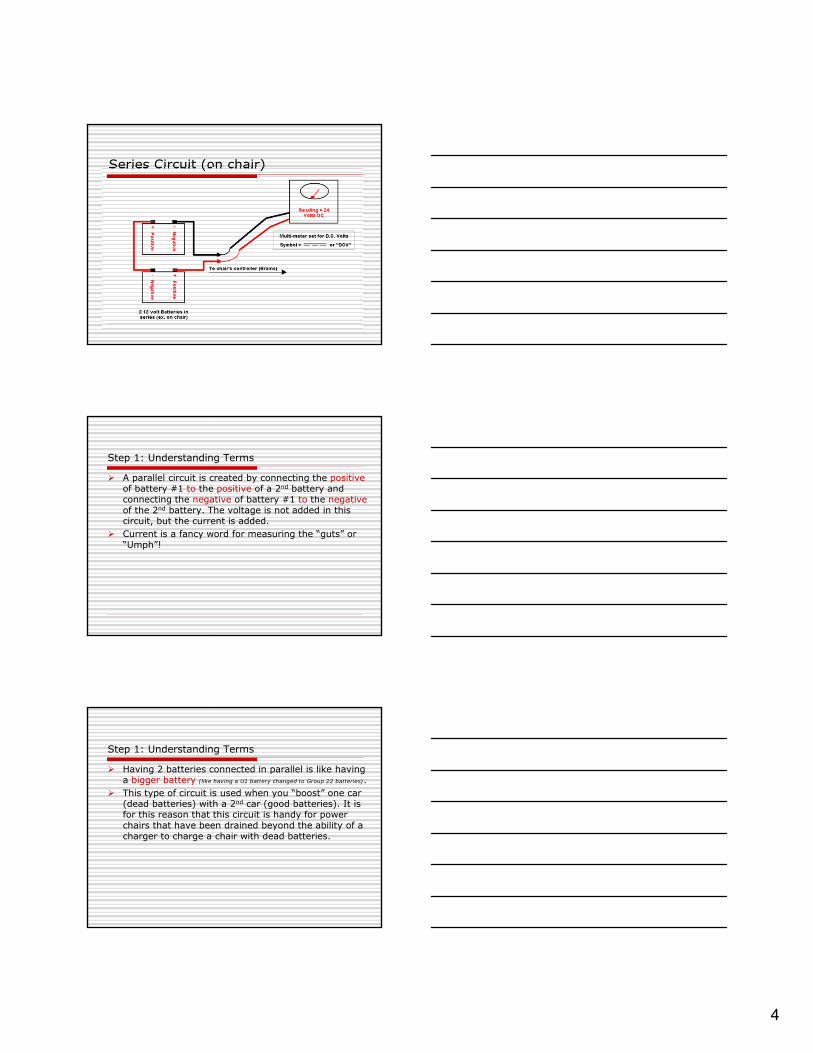
Series Circuit (on chair)
Step 1: Understanding Terms
Everything on a chair is powered by DC voltage (Direct Current). Direct Current or “DC” is a fancy word for “battery voltage” (this is the symbol: or “DCV”).
An electrical outlet on the wall is powered by AC voltage (Alternating Current). The symbol is ~ or “ACV” .
Step 1: Understanding Terms
There are 2 types of electrical circuits : Series and Parallel.
Series is how 2 batteries are connected on all power chairs.
In our power chairs 2 batteries are connected in series. The two batteries are connected by a connector going from the positive terminal of one battery to the negative of the 2nd battery. The remaining terminals (one + and one -) go to the chairs controller.
Two 12 volt batteries in series will equal 24 volts. In series circuits the two voltages add together(12v + 12v = 24v).
4
Series Circuit (on chair)
Step 1: Understanding Terms
A parallel circuit is created by connecting the positiveof battery #1 to the positive of a 2nd battery and connecting the negative of battery #1 to the negativeof the 2nd battery. The voltage is not added in this circuit, but the current is added.
Current is a fancy word for measuring the “guts” or “Umph”!
Step 1: Understanding Terms
Having 2 batteries connected in parallel is like having a bigger battery (like having a U1 battery changed to Group 22 batteries).
This type of circuit is used when you “boost” one car (dead batteries) with a 2nd car (good batteries). It is for this reason that this circuit is handy for power chairs that have been drained beyond the ability of a charger to charge a chair with dead batteries.
5
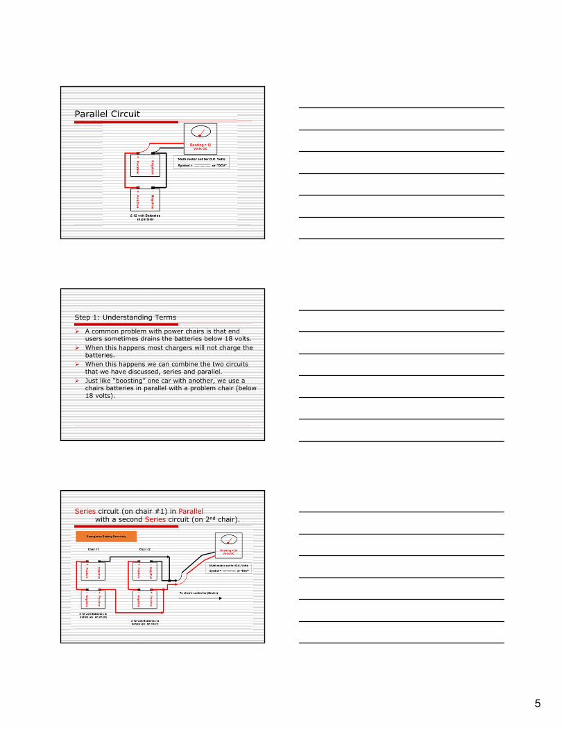
Parallel Circuit
Step 1: Understanding Terms
A common problem with power chairs is that end users sometimes drains the batteries below 18 volts.
When this happens most chargers will not charge the batteries.
When this happens we can combine the two circuits that we have discussed, series and parallel.
Just like “boosting” one car with another, we use a chairs batteries in parallel with a problem chair (below 18 volts).
Series circuit (on chair #1) in Parallelwith a second Series circuit (on 2nd chair).
6
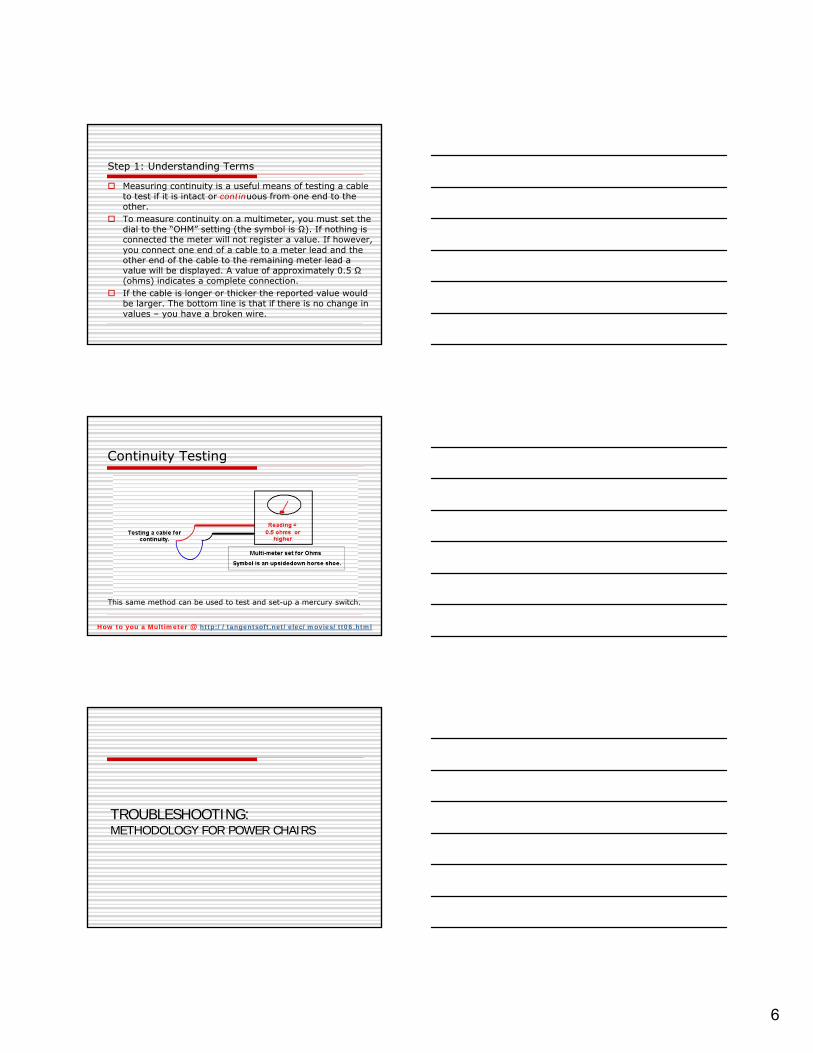
Step 1: Understanding Terms
Measuring continuity is a useful means of testing a cable to test if it is intact or continuous from one end to the other.
To measure continuity on a multimeter, you must set the dial to the “OHM” setting (the symbol is Ω). If nothing is connected the meter will not register a value. If however, you connect one end of a cable to a meter lead and the other end of the cable to the remaining meter lead a value will be displayed. A value of approximately 0.5 Ω (ohms) indicates a complete connection.
If the cable is longer or thicker the reported value would be larger. The bottom line is that if there is no change in values – you have a broken wire.
Continuity Testing
This same method can be used to test and set-up a mercury switch.
How to you a Multimeter @ http://tangentsoft.net/elec/movies/tt06.html
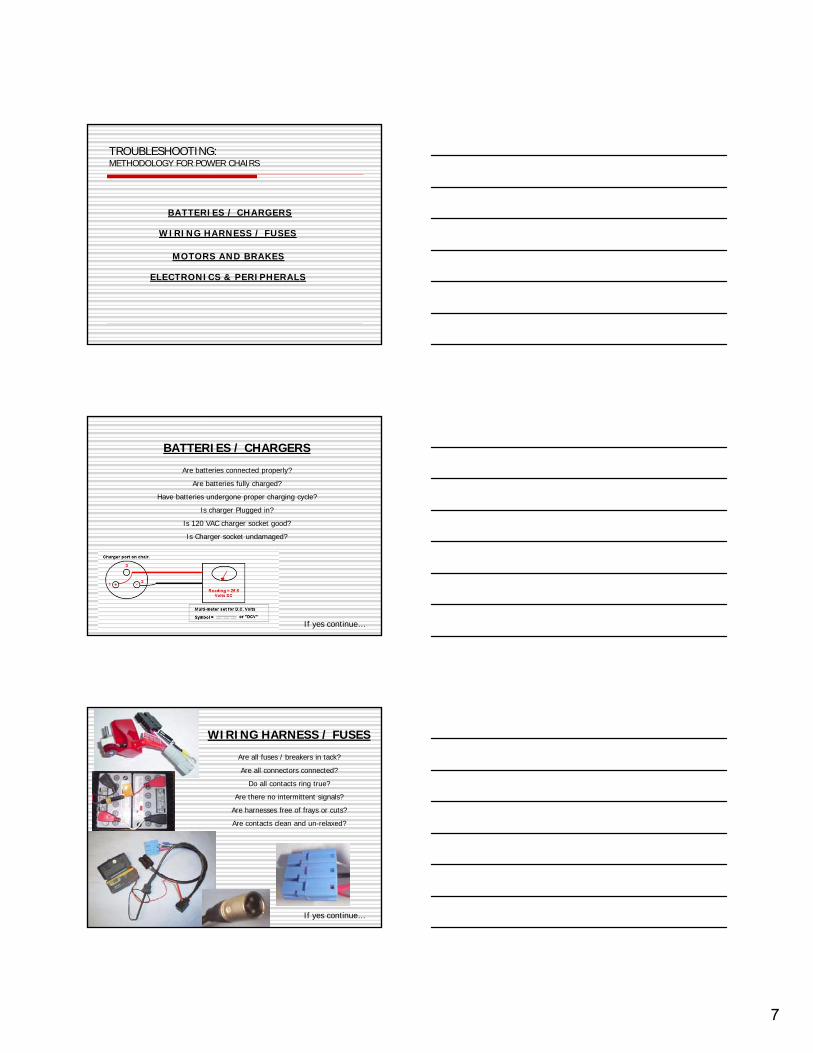
TROUBLESHOOTING:METHODOLOGY FOR POWER CHAIRS
7
TROUBLESHOOTING:METHODOLOGY FOR POWER CHAIRS
BATTERIES / CHARGERS
WIRING HARNESS / FUSES
MOTORS AND BRAKES
ELECTRONICS & PERIPHERALS
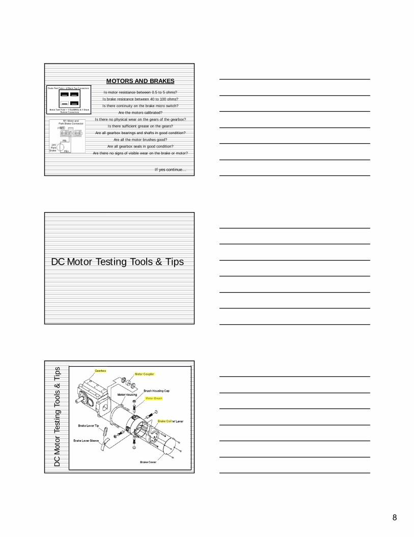
BATTERIES / CHARGERSAre batteries connected properly?
Are batteries fully charged?Have batteries undergone proper charging cycle?
Is charger Plugged in?Is 120 VAC charger socket good?Is Charger socket undamaged?
If yes continue…
WIRING HARNESS / FUSESAre all fuses / breakers in tack? Are all connectors connected?
Do all contacts ring true?Are there no intermittent signals?
Are harnesses free of frays or cuts?Are contacts clean and un-relaxed?
If yes continue…
8
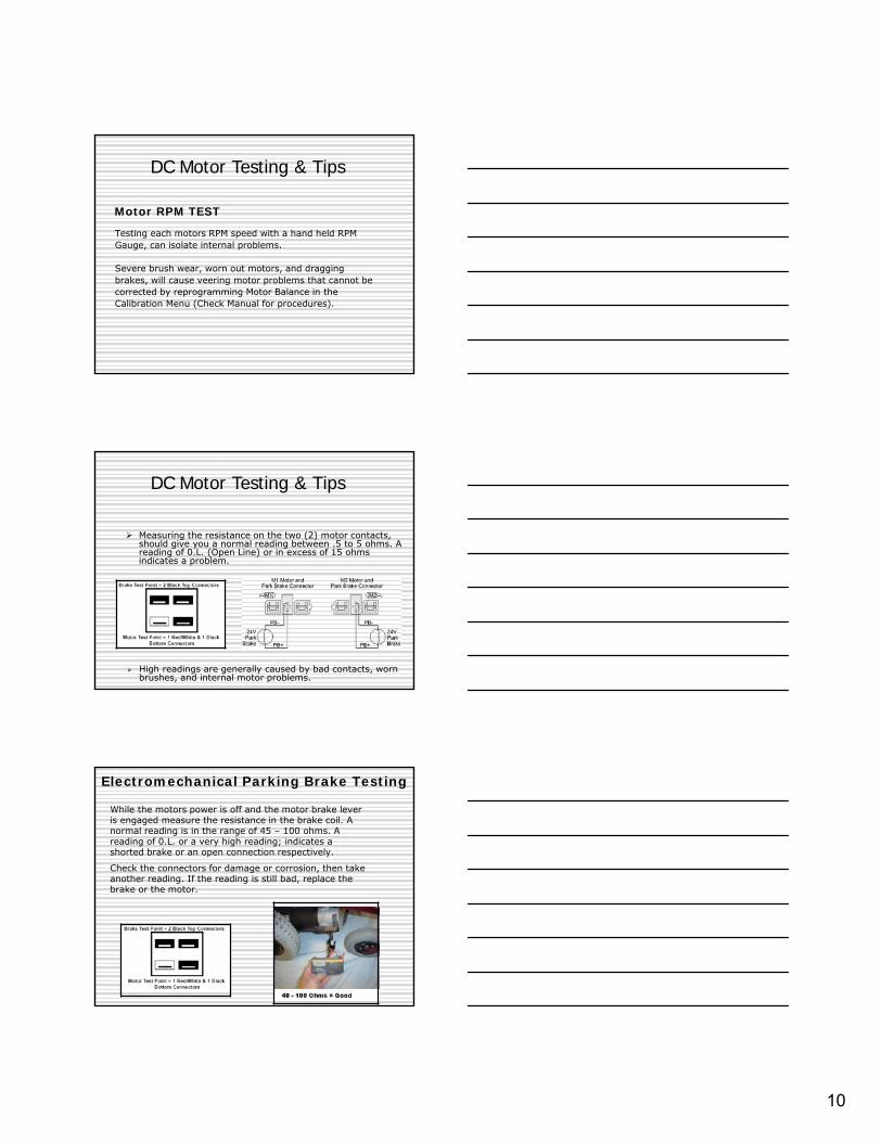
MOTORS AND BRAKESIs motor resistance between 0.5 to 5 ohms?Is brake resistance between 40 to 100 ohms?Is there continuity on the brake micro switch?
Are the motors calibrated?Is there no physical wear on the gears of the gearbox?
Is there sufficient grease on the gears?Are all gearbox bearings and shafts in good condition?
Are all the motor brushes good?Are all gearbox seals in good condition?
Are there no signs of visible wear on the brake or motor?
If yes continue…
DC Motor Testing Tools & Tips
DC M
otor
Tes
ting
Tool
s &
Tips

9
On average 40% of the motor problems can be fixed by replacing motor brushes.
Check the shunt wire for any discoloring, and check the spring for damage. If either is noticed replace the brush.
DC Motor Testing & Tips
Brushes should be replaced before the tamped shunt or pigtail lead has a chance to score the commutator.
DC Motor Testing & Tips
2 Pole Motor
4 Pole Motor2 Pole Motor TrueTrack-Gearless Brushless
•2 pole-generally found on the basic power wheelchairs (slower speeds, limited terrain, limited seating options)
•4 pole-generally found on rehab power wheelchairs(Varied terrains, powered seating, varied seating adjustments)
•TrueTrack-gearless/Brushless found on wheelchairs for use in varied terrain and those where endurance and energy consumption are issues)
DC Motor Testing & Tips
10
Testing each motors RPM speed with a hand held RPM Gauge, can isolate internal problems.
Severe brush wear, worn out motors, and dragging brakes, will cause veering motor problems that cannot be corrected by reprogramming Motor Balance in the Calibration Menu (Check Manual for procedures).
DC Motor Testing & Tips
Motor RPM TEST
Measuring the resistance on the two (2) motor contacts, should give you a normal reading between .5 to 5 ohms. A reading of 0.L. (Open Line) or in excess of 15 ohms indicates a problem.
DC Motor Testing & Tips
High readings are generally caused by bad contacts, worn brushes, and internal motor problems.
While the motors power is off and the motor brake lever is engaged measure the resistance in the brake coil. A normal reading is in the range of 45 – 100 ohms. A reading of 0.L. or a very high reading; indicates a shorted brake or an open connection respectively.
Check the connectors for damage or corrosion, then take another reading. If the reading is still bad, replace the brake or the motor.
Electromechanical Parking Brake Testing
11
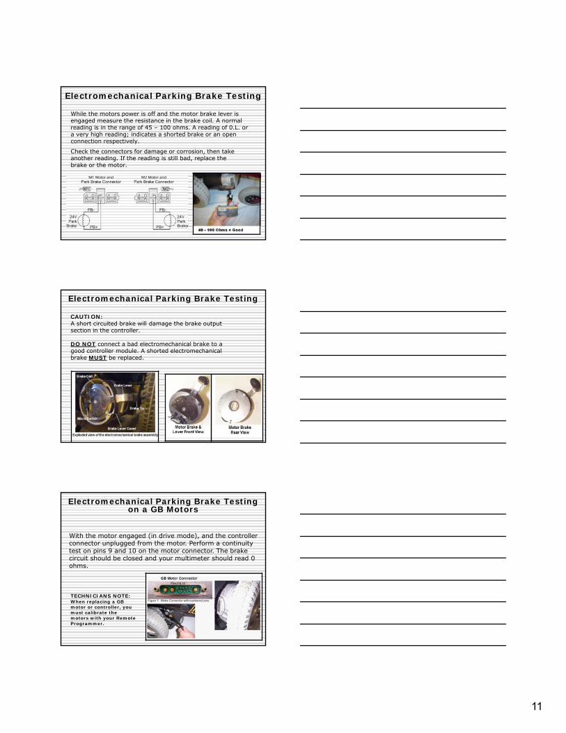
While the motors power is off and the motor brake lever is engaged measure the resistance in the brake coil. A normal reading is in the range of 45 – 100 ohms. A reading of 0.L. or a very high reading; indicates a shorted brake or an openconnection respectively.
Check the connectors for damage or corrosion, then take another reading. If the reading is still bad, replace the brake or the motor.
Electromechanical Parking Brake Testing
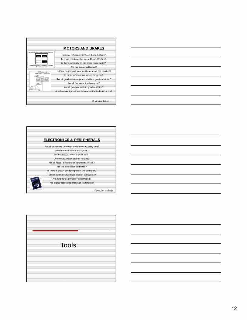
CAUTION:A short circuited brake will damage the brake output section in the controller.
DO NOT connect a bad electromechanical brake to a good controller module. A shorted electromechanical brake MUST be replaced.
Electromechanical Parking Brake Testing
With the motor engaged (in drive mode), and the controller connector unplugged from the motor. Perform a continuity test on pins 9 and 10 on the motor connector. The brake circuit should be closed and your multimeter should read 0 ohms.
TECHNICIANS NOTE: When replacing a GB motor or controller, you must calibrate the motors with your Remote Programmer.
Electromechanical Parking Brake Testing on a GB Motors
12
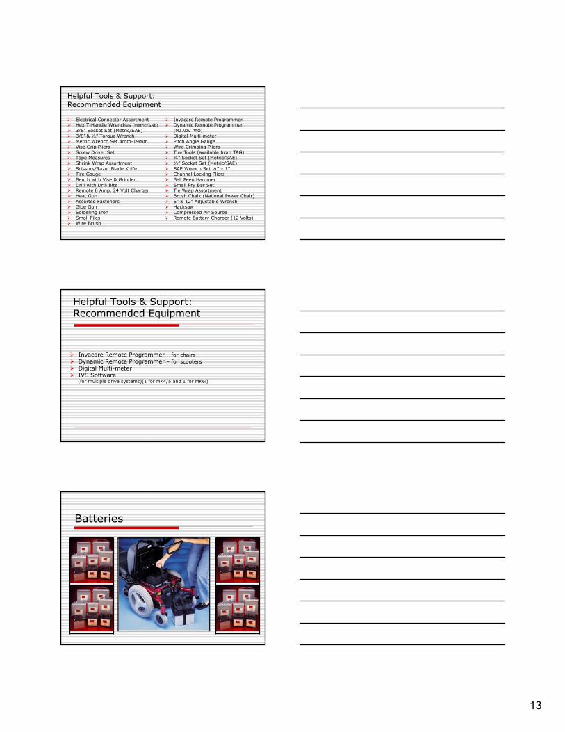
MOTORS AND BRAKESIs motor resistance between 0.5 to 5 ohms?Is brake resistance between 40 to 100 ohms?Is there continuity on the brake micro switch?
Are the motors calibrated?Is there no physical wear on the gears of the gearbox?
Is there sufficient grease on the gears?Are all gearbox bearings and shafts in good condition?
Are all the motor brushes good?Are all gearbox seals in good condition?
Are there no signs of visible wear on the brake or motor?
If yes continue…
ELECTRONICS & PERIPHERALSAre all connectors unbroken and do contacts ring true?
Are there no intermittent signals?Are harnesses free of frays or cuts?Are contacts clean and un-relaxed?
Are all fuses / breakers on peripherals in tact?Are the electronics calibrated?
Is there a known good program in the controller?Is there software /hardware version compatible?
Are peripherals physically undamaged?Are display lights on peripherals illuminated?
If yes, let us help.
Tools
13
Electrical Connector Assortment Hex T-Handle Wrenches (Metric/SAE) 3/8” Socket Set (Metric/SAE) 3/8’ & ½” Torque Wrench Metric Wrench Set 4mm-19mm Vise Grip Pliers Screw Driver Set Tape Measures Shrink Wrap Assortment Scissors/Razor Blade Knife Tire Gauge Bench with Vise & Grinder Drill with Drill Bits Remote 8 Amp, 24 Volt Charger Heat Gun Assorted Fasteners Glue Gun Soldering Iron Small Files Wire Brush
Helpful Tools & Support:Recommended Equipment
Invacare Remote Programmer Dynamic Remote Programmer
(PN ADV-PRO) Digital Multi-meter Pitch Angle Gauge Wire Crimping Pliers Tire Tools (available from TAG) ¼” Socket Set (Metric/SAE) ½” Socket Set (Metric/SAE) SAE Wrench Set ¼” – 1” Channel Locking Pliers Ball Peen Hammer Small Pry Bar Set Tie Wrap Assortment Brush Chalk (National Power Chair) 6” & 12” Adjustable Wrench Hacksaw Compressed Air Source Remote Battery Charger (12 Volts)
Helpful Tools & Support:Recommended Equipment
Invacare Remote Programmer – for chairs Dynamic Remote Programmer – for scooters Digital Multi-meter IVS Software
(for multiple drive systems)(1 for MK4/5 and 1 for MK6i)
Batteries

14
Two Types of Batteries
•Deep Cycle Gel Cell (recombinant battery)
•Lead Acid
Batteries
A Gel cell is a “recombinant” battery.
This means that the oxygen that is normally produced on the positive plate recombines with the hydrogengiven off by the negative plate.
The “recombination” of the hydrogen & oxygen produces water (H20), which replaces the moisture in the battery.
Therefore, the battery is maintenance-free, as it never needs water.
DEEP CYCLE GELL BATTERIES
Batteries
•An Ampere-Hour is a unit of measure for a battery's electrical storage capacity.
•Obtained by multiplying the current in amperes by the time in hours of discharge.
•A battery which delivers 5 amperes for 20 hours is a 100 Amp-Hr battery.
Batteries are rated in Amp Hours
Batteries
AH
CURRENT DRAW (AMPS) TIME (HR)x
15
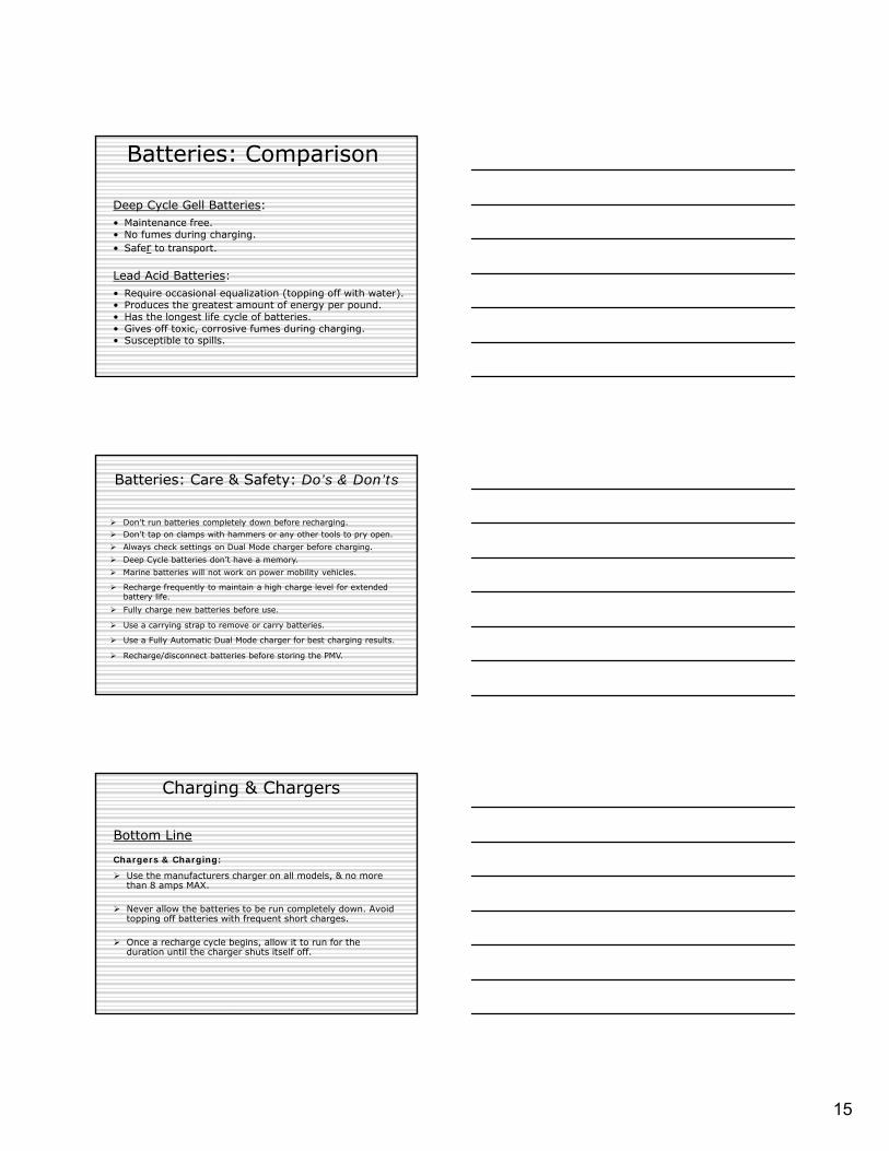
Deep Cycle Gell Batteries:• Maintenance free.• No fumes during charging.• Safer to transport.
Lead Acid Batteries:• Require occasional equalization (topping off with water).• Produces the greatest amount of energy per pound.• Has the longest life cycle of batteries.• Gives off toxic, corrosive fumes during charging.• Susceptible to spills.
Batteries: Comparison
Batteries: Care & Safety: Do’s & Don’ts
Don’t run batteries completely down before recharging. Don’t tap on clamps with hammers or any other tools to pry open. Always check settings on Dual Mode charger before charging. Deep Cycle batteries don’t have a memory. Marine batteries will not work on power mobility vehicles.
Recharge frequently to maintain a high charge level for extended battery life.
Fully charge new batteries before use.
Use a carrying strap to remove or carry batteries.
Use a Fully Automatic Dual Mode charger for best charging results.
Recharge/disconnect batteries before storing the PMV.
Chargers & Charging:
Use the manufacturers charger on all models, & no more than 8 amps MAX.
Never allow the batteries to be run completely down. Avoid topping off batteries with frequent short charges.
Once a recharge cycle begins, allow it to run for the duration until the charger shuts itself off.
Bottom Line
Charging & Chargers
16
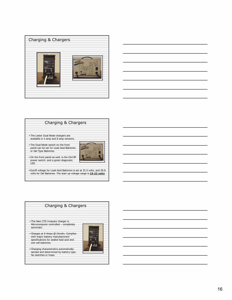
Charging & Chargers
•The Lester Dual Mode chargers are available in 4 amp and 8 amp versions.
•The Dual Mode switch on the front panel can be set for Lead Acid Batteries or Gel Type Batteries.
•On the front panel as well, is the On/Off power switch, and a green diagnostic LED.
•Cutoff voltage for Lead Acid Batteries is set at 31.0 volts, and 28.8 volts for Gel Batteries. The start up voltage range is 18-22 volts.
Charging & Chargers
•The New CTE Invacare charger is Microcomputer controlled – completely automatic.
•Charges at 8 Amps @ 24volts. Complies with major battery manufacturers’ specifications for sealed lead acid and wet cell batteries.
•Charging characteristics automatically sensed and determined by battery type. No switches or fuses.
Charging & Chargers

17
TECHNICIANS NOTE:
Allow eight (8) hours for normal charging. Larger batteries (greater than 55 ampere-hours) or severely discharged batteries may require up to sixteen (16) hours to be properly charged and equalized.
If charger operates for sixteen (16) hours and is unable to fully charge the batteries, an internal timer turns the charger off and begins to fast blink the green light.
Perform a load test on the batteries, and determine if replacements are needed.
Charging & Chargers
TROUBLE SHOOTING:Batteries/Chargers
How do you know if your charger did its job?
How do you know if your batteries are good?

18
Testing under load is the only way to spot the problem of faulty/old batteries.
Two methods: ON Chair (next) & OFF Chair (above).
Battery Testing Procedure with Load Tester
Battery Testing Procedure with Meter
Read the static battery voltage when Fully Charged. Fully Charged = 25.6 volts or higher.
Battery Testing Procedure with Meter
Could take up to 10 to 16 hours to reach full charge. Badly depleted batteries can rise rapidly during charging and cause a false reading. Shutting off too soon. If the batteries are too low for the OEM charger to begin, use a 12 volt charger (no more than 10 AMPS) on each battery for an hour (off chair). Then recharge the batteries (on chair) overnight with the OEM charger.
19
While monitoring the voltage of the battery we try to drive into a stationary object, tempting to stall the chair(Check manual for details of procedure before proceeding).
Caution:Be sure not to stall motors for longer than 15 seconds. Stalling the motors for more than 15 seconds, may cause hot spots on the commutator plates, or cause the chair to go into 100% Current Rollback
TECH NOTE:If the voltage drops to less than 23.1 volts from a pair of fully charged batteries while under load, they should be replaced regardless of the unloaded voltages.
Battery Testing Procedure without Load Tester
Battery Testing Procedure
After testing the batteries if they are found to be bad...Replace them.
Invacare Remote Programmers
20
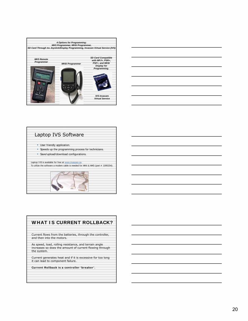
4 Options for Programming:MK5 Programmer, MK6i Programmer,
SD Card Through the Joystick/Display Programming, Invacare Virtual Service (IVS)
MK5 Remote Programmer
MK6i Programmer
SD Card Compatible with MPJ+, PSR+, PSF+, and MK6i
Display for Programming.
IVS Invacare Virtual Service
Laptop IVS Software
• User friendly application.
Laptop IVS is available for free at www.invacare.ca. To utilize the software a modem cable is needed for MK4 & MK5 (part # 1095204).
• Speeds up the programming process for technicians.• Save/upload/download configurations.
WHAT IS CURRENT ROLLBACK?
Current flows from the batteries, through the controller, and then into the motors.
As speed, load, rolling resistance, and terrain angle increases so does the amount of current flowing through the system.
Current generates heat and if it is excessive for too long it can lead to component failure.
Current Rollback is a controller ‘breaker’.
21
WHAT IS CURRENT ROLLBACK?
•Controller reaches current rollback setting•Controller will automatically reduce the output•Causes the chair to slow down or stop depending upon the load and operating terrain.
•Controller has an internal timer that keeps the operating system at this reduced output until the system has had time to cool down.
•Once it counts down full power output is restored
What increases the risk of current rollback?
Terrain Angle - Inclines require the system to work harder as you fight gravity.
Weight - Weight includes the user in the chair as well as all other accessories mounted to the chair.
Rolling Resistance – The surface that the chair is operating on makes a difference to how hard the chair has to work. ex. sand/grass
What increases the risk of current rollback?
Speed – Combine high-speed settings with factors prior and you run the risk of going into current rollback.
A big factor that leads to a chair going into current rollback is front loading.
Front loading occurs when an excessive amount of the user’s weight rests on the front casters and not the drive wheels. Rear wheel drive chairs are designed to carry weight and not push it.
22
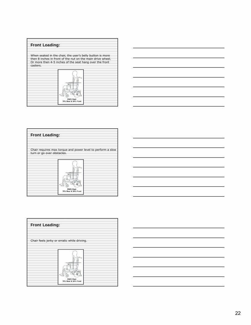
Front Loading:
When seated in the chair, the user’s belly button is more then 8 inches in front of the nut on the main drive wheel. Or more then 4-5 inches of the seat hang over the front casters.
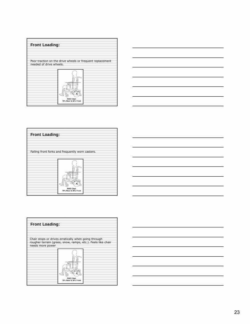
Front Loading:
Chair requires max torque and power level to perform a slow turn or go over obstacles.
Chair feels jerky or erratic while driving.
Front Loading:
23
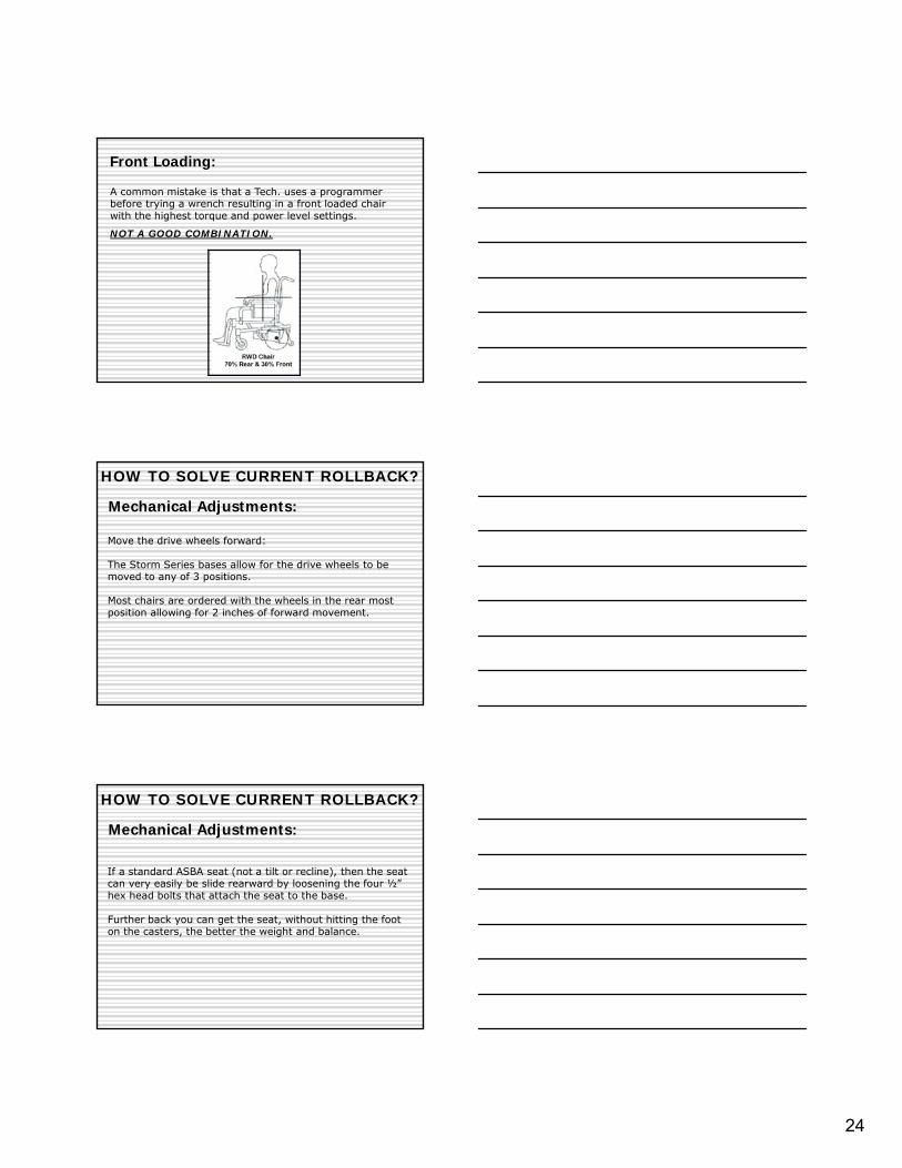
Poor traction on the drive wheels or frequent replacement needed of drive wheels.
Front Loading:
Failing front forks and frequently worn casters.
Front Loading:
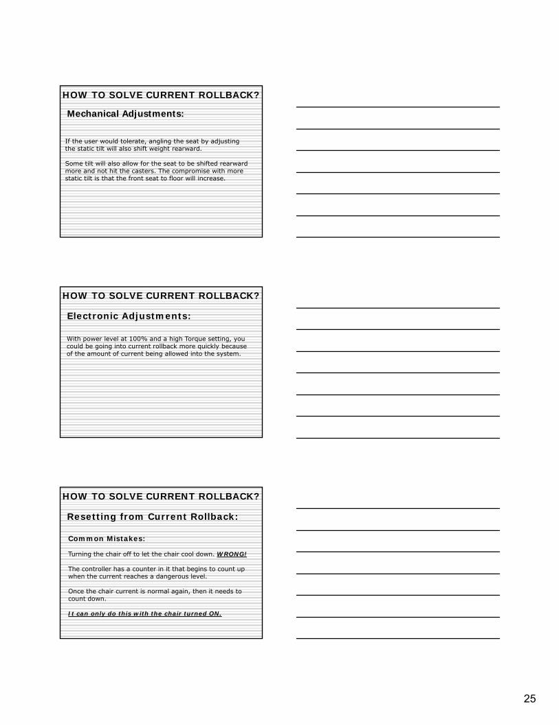
Chair stops or drives erratically when going through rougher terrain (grass, snow, ramps, etc.). Feels like chair needs more power
Front Loading:
24
A common mistake is that a Tech. uses a programmer before trying a wrench resulting in a front loaded chair with the highest torque and power level settings.
NOT A GOOD COMBINATION.
Front Loading:
Move the drive wheels forward:
The Storm Series bases allow for the drive wheels to be moved to any of 3 positions.
Most chairs are ordered with the wheels in the rear most position allowing for 2 inches of forward movement.
HOW TO SOLVE CURRENT ROLLBACK?
Mechanical Adjustments:
Mechanical Adjustments:
If a standard ASBA seat (not a tilt or recline), then the seat can very easily be slide rearward by loosening the four ½” hex head bolts that attach the seat to the base.
Further back you can get the seat, without hitting the foot on the casters, the better the weight and balance.
HOW TO SOLVE CURRENT ROLLBACK?
25
HOW TO SOLVE CURRENT ROLLBACK?
Mechanical Adjustments:
If the user would tolerate, angling the seat by adjusting the static tilt will also shift weight rearward.
Some tilt will also allow for the seat to be shifted rearward more and not hit the casters. The compromise with more static tilt is that the front seat to floor will increase.
Electronic Adjustments:
With power level at 100% and a high Torque setting, you could be going into current rollback more quickly because of the amount of current being allowed into the system.
HOW TO SOLVE CURRENT ROLLBACK?
Resetting from Current Rollback:
Common Mistakes:
Turning the chair off to let the chair cool down. WRONG!
The controller has a counter in it that begins to count up when the current reaches a dangerous level.
Once the chair current is normal again, then it needs to count down.
It can only do this with the chair turned ON.
HOW TO SOLVE CURRENT ROLLBACK?

26
Resetting from Current Rollback:
Common Mistakes:
If someone claims to be in a state of constant current rollback, then chances are that they are turning their chair off and the counter is remaining high, so that it only takes a little bit of driving to go back into rollback.
HOW TO SOLVE CURRENT ROLLBACK?
Resetting from Current Rollback:
Solution:
Charge the chair with the power on.
This ensures that the counter is zeroed and the batteries are full.
HOW TO SOLVE CURRENT ROLLBACK?
TROUBLE SHOOTING:Messages
27
Ways of diagnosing error/problems:
1.- Diagnostic codes via ERP Programmer.
2.- Diagnostic lights via SPJ, SPJ+, SPJ-80 & CSPJ Joysticks.
3.- Diagnostic icons on MPJ’s, PSR’s, PSF’s joysticks and
Dispay’s.
Thank you for your time.I have been your presenter,
Rick Alves