Embed Size (px)
Citation preview

IntesisBox Modbus Server LG Air Conditioning
User’s Manual Issue Date: 06/2016
r1 eng
IntesisBox® Modbus Server – LG AC User’s Manual r1 eng
© Intesis Software S.L. - All rights reserved This information is subject to change without notice
IntesisBox® is a registered trademark of Intesis Software SL
URL Email tel
http://www.intesis.com [email protected] +34 938047134
2 / 24
© Intesis Software S.L. 2016 All Rights Reserved. Information in this document is subject to change without notice. The software described in this document is furnished under a license agreement or nondisclosure agreement. The software may be used only in accordance with the terms of those agreements. No part of this publication may be reproduced, stored in a retrieval system or transmitted in any form or any means electronic or mechanical, including photocopying and recording for any purpose other than the purchaser’s personal use without the written permission of Intesis Software S.L.
Intesis Software S.L. Milà i Fontanals, 1 bis 08700 Igualada Spain TRADEMARKS All trademarks and tradenames used in this document are acknowledged to be the copyright of their respective holders.

IntesisBox® Modbus Server – LG AC User’s Manual r1 eng
© Intesis Software S.L. - All rights reserved This information is subject to change without notice
IntesisBox® is a registered trademark of Intesis Software SL
URL Email tel
http://www.intesis.com [email protected] +34 938047134
3 / 24
Gateway for the integration of LG compatible systems into Modbus (RTU and TCP) control and monitoring systems. Five models are available for this gateway, with the following Order Codes: LG-AC-MBS-4 Model supporting up to 4 indoor units. LG-AC-MBS-8 Model supporting up to 8 indoor units. LG-AC-MBS-32 Model supporting up to 32 indoor units. LG-AC-MBS-64 Model supporting up to 64 indoor units.

IntesisBox® Modbus Server – LG AC User’s Manual r1 eng
© Intesis Software S.L. - All rights reserved This information is subject to change without notice
IntesisBox® is a registered trademark of Intesis Software SL
URL Email tel
http://www.intesis.com [email protected] +34 938047134
4 / 24
INDEX
1. Description ......................................................................................................... 5 1.1 Introduction .................................................................................................... 5 1.2 Integration signals ........................................................................................... 5 1.3 Functionality ................................................................................................... 6 1.4 Capacity of IntesisBox ...................................................................................... 7
2. Modbus interface of IntesisBox .............................................................................. 8 2.1 Functions supported ......................................................................................... 8 2.2 Modbus RTU .................................................................................................... 8 2.3 Modbus TCP .................................................................................................... 8 2.4 Address Map ................................................................................................... 8
2.4.1 Modbus addresses related to Indoor Units 1…64 ............................................ 8 3. LinkBoxMB. Configuration & monitoring tool. ......................................................... 10
3.1 Introduction .................................................................................................. 10 3.2 Connections configuration ............................................................................... 10
3.2.1 Configuration tab ..................................................................................... 10 3.2.2 Modbus map tab ...................................................................................... 13
3.3 Sending the configuration to IntesisBox ............................................................ 14 3.4 Signals viewer ............................................................................................... 14 3.5 Files ............................................................................................................. 15
4. Setup process and troubleshooting ...................................................................... 16 4.1 Pre-requisites ................................................................................................ 16 4.2 Setup procedure ............................................................................................ 16
5. Connections ...................................................................................................... 17 6. Functional characteristics .................................................................................... 18 7. Mechanical & Electrical characteristics .................................................................. 19 8. Dimensions ....................................................................................................... 20 9. AC Unit Types compatibility ................................................................................ 21 10. Error codes for Indoor and Outdoor Units ............................................................. 21 11. Annexes ........................................................................................................... 22
11.1 PMNFP14Ax and PHNFP14A0 connection boards ................................................. 22 11.1.1 PMNFP14Ax ............................................................................................. 22 11.1.2 PHNFP14A0 ............................................................................................. 23
11.2 Indoor unit PCB address ................................................................................. 24

IntesisBox® Modbus Server – LG AC User’s Manual r1 eng
© Intesis Software S.L. - All rights reserved This information is subject to change without notice
IntesisBox® is a registered trademark of Intesis Software SL
URL Email tel
http://www.intesis.com [email protected] +34 938047134
5 / 24
1. Description
1.1 Introduction
IntesisBox Modbus Server – LG AC is a communication gateway for LG AC system integration into a Modbus supervision/control/automation system through PLC, SCADA and in general through any device or system with a Modbus mastering (TCP or RTU) interface. Thanks to IntesisBox, up to 64 Indoor Units can be integrated, allowing a maximum of 4 indoor units (LG-AC-MBS-4), 8 indoor units (LG-AC-MBS-8), 32 indoor units (LG-AC-MBS-32) or 64 indoor units (LG-AC-MBS-64). This integration may require the LG AC system being equipped with a LG PI485 interface. Otherwise, direct connection to the outdoor unit will be enough. PI485 interface is supplied by LG. Contact your nearest LG AC Systems distributor for details.
1.2 Integration signals
Following is the list of parameters that can be monitored/controlled on the indoor and outdoor units using IntesisBox:
Signal Indoor Unit Type
AC Vent DX AWHP
Communication AC Error R R R R
On/Off RW - RW RW
Mode RW - RW RW
Set Point Temperature RW - RW -
Ambient Temperature R - R R
Swing RW - - -
Fan Speed RW RW RW -
Remote Control RW RW RW RW
Error Code R R R R
Error Sign R R R R
On/Off (VENT) - RW RW -
Mode (VENT) - RW RW -
Filter Alarm - R - -
Supply Air Temperature - - R -
Outdoor Air Temperature - - R -
Heater - - RW -
Power Saving - - RW -
Rapidity - - RW -
Humidifier - - R -
Set Point Temperature Mode - - - R
Set Point Temperature AWHP - - - RW
Hot Water On/Off - - - RW
Hot Water Only - - - R
Set Point for Hot Water - - - RW
Water Inlet Temperature - - - R
Water Discharge Temperature - - - R
Water Tank Temperature - - - R
Solar Source Temperature - - - R
Accumulated Power (if PDI is present) R - R R
IntesisBox® Modbus Server – LG AC User’s Manual r1 eng
© Intesis Software S.L. - All rights reserved This information is subject to change without notice
IntesisBox® is a registered trademark of Intesis Software SL
URL Email tel
http://www.intesis.com [email protected] +34 938047134
6 / 24
1.3 Functionality
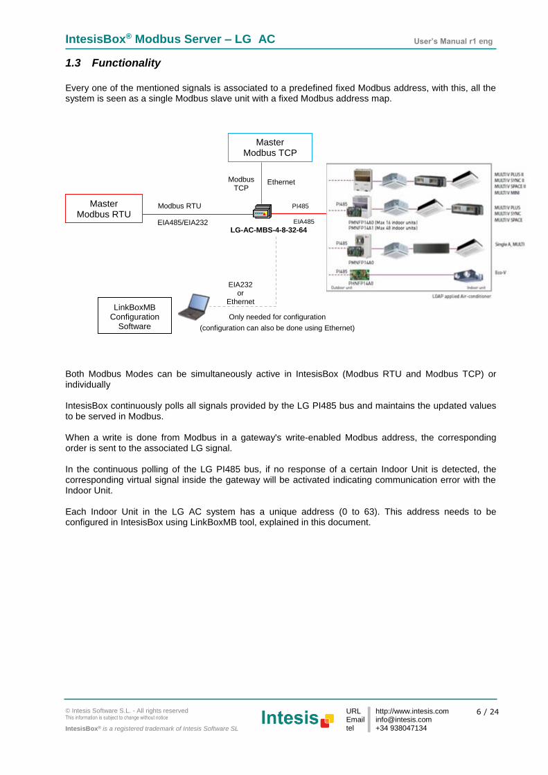
Every one of the mentioned signals is associated to a predefined fixed Modbus address, with this, all the system is seen as a single Modbus slave unit with a fixed Modbus address map. Both Modbus Modes can be simultaneously active in IntesisBox (Modbus RTU and Modbus TCP) or individually IntesisBox continuously polls all signals provided by the LG PI485 bus and maintains the updated values to be served in Modbus. When a write is done from Modbus in a gateway's write-enabled Modbus address, the corresponding order is sent to the associated LG signal. In the continuous polling of the LG PI485 bus, if no response of a certain Indoor Unit is detected, the corresponding virtual signal inside the gateway will be activated indicating communication error with the Indoor Unit. Each Indoor Unit in the LG AC system has a unique address (0 to 63). This address needs to be configured in IntesisBox using LinkBoxMB tool, explained in this document.
Ethernet
EIA232 or
Ethernet
Only needed for configuration
(configuration can also be done using Ethernet)
LinkBoxMB Configuration
Software
LG-AC-MBS-4-8-32-64
PI485
EIA485/EIA232
Modbus TCP
Modbus RTU
EIA485
Master Modbus TCP
Master Modbus RTU

IntesisBox® Modbus Server – LG AC User’s Manual r1 eng
© Intesis Software S.L. - All rights reserved This information is subject to change without notice
IntesisBox® is a registered trademark of Intesis Software SL
URL Email tel
http://www.intesis.com [email protected] +34 938047134
7 / 24
1.4 Capacity of IntesisBox
Element
Max. Notes
Number of indoor units
64* Maximum number AC indoor units that can be controlled
Number of LG PI485 connections 16 Maximum number of PI485 Cards or Outdoor Units (if no PI485 card is required) that can be connected to a single IntesisBox
Number of variables per indoor unit
30 Modbus addresses
Maximum number of variables
1920* Modbus addresses
*There are four different models of IntesisBox Modbus Server – LG AC each with different capacity. The table above shows the capacity for the top model (with maximum capacity). Their order codes are:
Model supporting up to 4 LG indoor units. Ref.: LG-AC-MBS-4 Model supporting up to 8 LG indoor units. Ref.: LG-AC-MBS-8 Model supporting up to 32 LG indoor units. Ref.: LG-AC-MBS-32 Model supporting up to 64 LG indoor units. Ref.: LG-AC-MBS-64
IntesisBox® Modbus Server – LG AC User’s Manual r1 eng
© Intesis Software S.L. - All rights reserved This information is subject to change without notice
IntesisBox® is a registered trademark of Intesis Software SL
URL Email tel
http://www.intesis.com [email protected] +34 938047134
8 / 24
2. Modbus interface of IntesisBox
2.1 Functions supported
This part is common for Modbus RTU and TCP. Modbus functions 03 and 04 (read holding registers and read input registers) can be used to read Modbus registers. Modbus function 06 (Single Holding Registers) and 16 (Write Multiple Holding Registers) must be used to write Modbus registers. As per Modbus standard specification, register contents are always expressed in MSB..LSB. Modbus error codes are fully supported; they will be sent whenever a non-valid Modbus action or address is required.
2.2 Modbus RTU
Baud rate can be selected from 1200, 2400, 4800, 9600, 19200, 38400 and 56700. Data Bits: 8 Parity can be selected from none, even and odd. Stop Bits can be selected from 1 and 2. Modbus slave number can be configured. Physical connection (EIA232 or EIA485) can also be selected. Only the lines RX, TX and GND of the EIA232 connector are used (TX and RX for EIA485).
2.3 Modbus TCP
The TCP port to use can be configured (by default 502 is used). The IP address, subnet mask and default gateway address to use by IntesisBox can be also configured.
2.4 Address Map
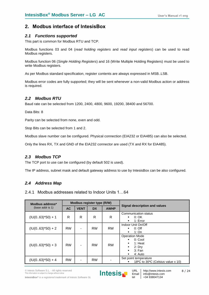
2.4.1 Modbus addresses related to Indoor Units 1…64
Modbus address* (base addr is 1)
Modbus register type (R/W) Signal description and values
AC VENT DX AWHP
(IU(0..63)*50) + 1 R R R R Communication status
0: OK 1: Error
(IU(0..63)*50) + 2 RW - RW RW Indoor Unit On/Off
0: Off 1: On
(IU(0..63)*50) + 3 RW - RW RW
Operation Mode 0: Cool 1: Heat 2: Dry 3: Fan 4: Auto
(IU(0..63)*50) + 4 RW - RW - Set point temperature
18ºC to 30ºC (Celsius value x 10)
IntesisBox® Modbus Server – LG AC User’s Manual r1 eng
© Intesis Software S.L. - All rights reserved This information is subject to change without notice
IntesisBox® is a registered trademark of Intesis Software SL
URL Email tel
http://www.intesis.com [email protected] +34 938047134
9 / 24
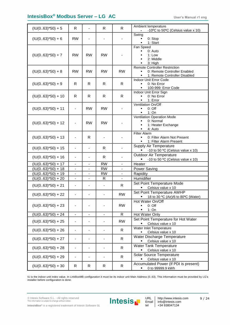
(IU(0..63)*50) + 5 R - R R Ambient temperature
-10ºC to 50ºC (Celsius value x 10)
(IU(0..63)*50) + 6 RW - - - Swing
0: Stop 1: Start
(IU(0..63)*50) + 7 RW RW RW -
Fan Speed 0: Auto 1: Low 2: Middle 3: High
(IU(0..63)*50) + 8 RW RW RW RW Remote Controller Restriction
0: Remote Controller Enabled 1: Remote Controller Disabled
(IU(0..63)*50) + 9 R R R R Indoor Unit Error Code
0: No Error 100-999: Error Code
(IU(0..63)*50) + 10 R R R R Indoor Unit Error Sign
0: No Error 1: Error
(IU(0..63)*50) + 11 - RW RW - Ventilation On/Off
0: Off 1: On
(IU(0..63)*50) + 12 - RW RW -
Ventilation Operation Mode 0: Normal 1: Heater Exchange 4: Auto
(IU(0..63)*50) + 13 - R - - Filter Alarm
0: Filter Alarm Not Present 1: Filter Alarm Present
(IU(0..63)*50) + 15 - - R - Supply Air Temperature
-10 to 50 ºC (Celsius value x 10)
(IU(0..63)*50) + 16 - - R - Outdoor Air Temperature
-10 to 50 ºC (Celsius value x 10)
(IU(0..63)*50) + 17 - - RW - Heater
(IU(0..63)*50) + 18 - - RW - Power Saving
(IU(0..63)*50) + 19 - - RW - Rapidity
(IU(0..63)*50) + 20 - - R - Humidifier
(IU(0..63)*50) + 21 - - - R Set Point Temperature Mode
Celsius value x 10
(IU(0..63)*50) + 22 - - - RW Set Point Temperature AWHP
18 to 30 ºC (Air)/6 to 80ºC (Water)
(IU(0..63)*50) + 23 - - - RW Hot Water On/Off
0: Off
1: On
(IU(0..63)*50) + 24 - - - R Hot Water Only
(IU(0..63)*50) + 25 - - - RW Set Point Temperature for Hot Water
Celsius value x 10
(IU(0..63)*50) + 26 - - - R Water Inlet Temperature
Celsius value x 10
(IU(0..63)*50) + 27 - - - R Water Discharge Temperature
Celsius value x 10
(IU(0..63)*50) + 28 - - - R Water Tank Temperature
Celsius value x 10
(IU(0..63)*50) + 29 - - - R Solar Source Temperature
Celsius value x 10
(IU(0..63)*50) + 30 R R R R Accumulated Power (If PDI is present)
0 to 99999.9 kWh
IU is the indoor unit index value. In LinkBoxMB configuration it must be its indoor unit Main Address (0..63). This information must be provided by LG’s installer before configuration is done.
IntesisBox® Modbus Server – LG AC User’s Manual r1 eng
© Intesis Software S.L. - All rights reserved This information is subject to change without notice
IntesisBox® is a registered trademark of Intesis Software SL
URL Email tel
http://www.intesis.com [email protected] +34 938047134
10 / 24
3. LinkBoxMB. Configuration & monitoring tool.
3.1 Introduction
LinkBoxMB is a Windows® compatible software developed specifically to monitor and configure IntesisBox Modbus Server series. The installation procedure and main functions are explained in the LinkBoxMB User Manual. This document can be found in the Doc folder, or can be downloaded from the link indicated in the installation sheet supplied with the IntesisBox device. In this section, only the specific case of LG indoor unit’s integration to Modbus networks will be covered.
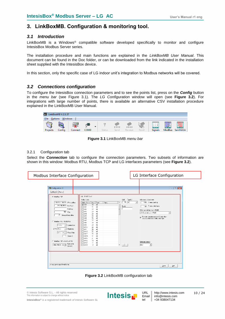
3.2 Connections configuration
To configure the IntesisBox connection parameters and to see the points list, press on the Config button in the menu bar (see Figure 3.1). The LG Configuration window will open (see Figure 3.2). For integrations with large number of points, there is available an alternative CSV installation procedure explained in the LinkBoxMB User Manual.
Figure 3.1 LinkBoxMB menu bar
3.2.1 Configuration tab
Select the Connection tab to configure the connection parameters. Two subsets of information are shown in this window: Modbus RTU, Modbus TCP and LG interfaces parameters (see Figure 3.2).
Figure 3.2 LinkBoxMB configuration tab
Modbus Interface Configuration LG Interface Configuration

IntesisBox® Modbus Server – LG AC User’s Manual r1 eng
© Intesis Software S.L. - All rights reserved This information is subject to change without notice
IntesisBox® is a registered trademark of Intesis Software SL
URL Email tel
http://www.intesis.com [email protected] +34 938047134
11 / 24
Modbus interface configuration parameters:
Figure 3.3 Modbus Interface Configuration
1. Select the type of Modbus communication to use (TCP, RTU or both).
If Modbus TCP is selected, then:
2. IP IntesisBox: Enter the IP address for IntesisBox.
3. Net Mask: Enter the IP net mask for IntesisBox.
4. Gateway: Enter the default gateway address for IntesisBox; leave it blank if no router is needed.
5. Port: Enter the TCP port to use (default for Modbus TCP is 502).
6. Timeout Keep Alive: Enter the time (expressed in seconds) that IntesisBox will wait, upon no
TCP activity, to send a Keep Alive packet. Enter 0 if you don’t want IntesisBox to send any Keep Alive packet (default 30 seconds).
If Modbus RTU is selected, then:
7. Connection: Select the physical media (EIA232 or EIA485)1.
8. Baud rate: Enter the baud rate of the serial communication.
9. Parity: Enter the byte parity of the serial communication.
10. Slave: Introduce the Slave number for the Modbus interface.
11. Byte Order (32 bits): Select the proper Byte order for the 32 bits Modbus register to match
your Modbus Master format type.
1 In the LinkBoxMB this connection is labeled as EIA232 and EIA485 respectively.
1
2
3
4
6
7
8
9
5
10
11

IntesisBox® Modbus Server – LG AC User’s Manual r1 eng
© Intesis Software S.L. - All rights reserved This information is subject to change without notice
IntesisBox® is a registered trademark of Intesis Software SL
URL Email tel
http://www.intesis.com [email protected] +34 938047134
12 / 24
LG (PI485 Card) interface configuration parameters:
Figure 3.4 LG AC Configuration
1. Indoor Units list. In this list, you can individually enable each of the 64 indoor units available on the system. The index in the column “Indoor unit” (i.e. the number x in “IU-xxx”) is the reference that will be used later on (in tab “Signals”) to refer to this AC indoor unit. Values for columns “Add”, “Type” and “Name” in each indoor unit (IU) can be changed by selecting the IU in the list, by means of textboxes 2, 3 and 4.
2. Indoor Unit address. Main address of the Indoor Unit. 3. Name. Optionally you can enter a name, which will appear on the list (1), for each IU.
4. Indoor Unit Type. You need to select the type of indoor unit so the right signals can be applied. By
default, it is set to AC type.
Additional configuration parameters below should generally be left to their default value. They only might need to be tuned in some very specific cases (installations with large number of units, scenarios with large bursts of commands sent at once…)
5. Timeout polling. Time waiting response from the LG PI485 bus when polling is performed. 6. Timeout interframe. Minimum time between RX and TX frames sent to the LG PI485 bus.
7. Other control devices in PI485. In this list you will be able to select between:
No other controller in PI485: That means that the IntesisBox is the only controller present in the PI485 bus.
LG Slave device in PI485: That means that there is second controller in the LG PI485 bus working as a Slave.
1 2 3 4
5
6
7
8
9

IntesisBox® Modbus Server – LG AC User’s Manual r1 eng
© Intesis Software S.L. - All rights reserved This information is subject to change without notice
IntesisBox® is a registered trademark of Intesis Software SL
URL Email tel
http://www.intesis.com [email protected] +34 938047134
13 / 24
LG Slave device in PI485, with PDI feature: That means that there is second controller in the LG PI485 bus working as a Slave and support PDI (Power Distribution Indication) feature.
8. Execute operation on the AC only when value written from Modbus changes. If this check box is
selected, commands to the AC system will only be sent if they have a different value from the current one. This is used to avoid overflow of the communication between the AC system and the IntesisBox.
On the contrary, if this parameter is unchecked, then the commands will be sent to the AC system every time they are received from the Modbus side, independently from its value. Default and recommended value is checked.
9. Gateway version. In the right lower part of the IntesisBox configuration window, select which version
of the IntesisBox Modbus Server – LG gateway you are to set up. (64AC for LG-AC-MBS-64, 32AC for LG-AC-MBS-32, 8AC for LG-AC-MBS-8 or 4AC for LG-AC-MBS-4).
3.2.2 Modbus map tab
In order to know the Modbus map that is going to be used by the interface, the Modbus map tab can be consulted. Content in this tab is just informative: no information has to be set up.
Figure 3.5 Signals list
1. Address Formula: Formula used by IntesisBox to define the Modbus address for the point. Use this address (obtained with this formula) to access the point from your Modbus master device.
2. R/W: Indicates if the signal is read-only, write-only or if it can be read and written (from the Modbus system point of view). Depending on the different indoor unit type some of them will be available and some others will not.
3. Signal: Signal description.
4. Values: Possible values for the signal. See section 2.4 for further detail on address map and the possible values on each signal.
1 2 3 4

IntesisBox® Modbus Server – LG AC User’s Manual r1 eng
© Intesis Software S.L. - All rights reserved This information is subject to change without notice
IntesisBox® is a registered trademark of Intesis Software SL
URL Email tel
http://www.intesis.com [email protected] +34 938047134
14 / 24
3.3 Sending the configuration to IntesisBox
When the configuration is finished, follow the next steps.
1.- Click on Save button to save the project to the project folder on your hard disk (more information in LinkBoxMB User Manual).
2.- You will be prompted to generate the configuration file to be sent to the gateway.
a.- If Yes is selected, the binary file (LGE.Lbox) containing the configuration for the gateway will be generated and saved also into the project folder. b.- If NO is selected, remember that the binary file with the project needs to be generated before the IntesisBox starts to work as expected.
3.- Once in the configuration window again, click on exit. Configuration file is ready to be sent to the IntesisBox device.
4.- Press the Send File button to send the binary file to the IntesisBox device. The process of file transmission can be monitored in the IntesisBox Communication Console window. IntesisBox will reboot automatically once the new configuration is loaded.
After any configuration change, do not forget to send the configuration file to the IntesisBox using button Send File.
3.4 Signals viewer
Once the gateway is running with the correct configuration, to supervise the status of the configured signals, press the Signals button on the menu bar (see Figure 3.1). The Signals Viewer window will open (see Figure 3.6). This window shows all signals active within the gateway with its main configuration parameters and its real time value1 in the Value column.
Figure 3.6 LinkBoxMB Signals Viewer
1 In case you connect to the IntesisBox when it’s been running for a certain time, you should press the Refresh
button to get updated values. After pressing Refresh, all signal values will keep continuously updated until the
connection is closed.

IntesisBox® Modbus Server – LG AC User’s Manual r1 eng
© Intesis Software S.L. - All rights reserved This information is subject to change without notice
IntesisBox® is a registered trademark of Intesis Software SL
URL Email tel
http://www.intesis.com [email protected] +34 938047134
15 / 24
The signals viewer can be used even though only one system is connected to the IntesisBox, Modbus or LG AC. Therefore, it becomes convenient for supervision and testing the system. In order to force a specific value to a signal, double-click its row in the table. This will display a dialog in which the desired value can be entered (see Figure 3.7). Changing its value in this way, will make:
The content of the corresponding Modbus address will be changed to this value.
If the signal is write-enabled, it will trigger a suitable command to LG AC system.
Figure 3.7 Signal value change window
3.5 Files
LinkBoxMB saves the integration configuration in the following files inside the project folder:
PROJECT.INI INI file containing general information related to the project
LGE.INI INI file containing information related with the values configured through the “Connection” tab in IntesisBox configuration
LGE.LBOX Binary file created from the information in the files described above. This is the file downloaded to the IntesisBox.
Table 3.1 LinkBoxMB generated files during Project creation
It is strongly recommended to back up the project folder containing these files in external media, once the installation process is finished. This way you will be able to do future configuration changes in case of reinstallation of LinkBoxMB due, for example, to a failure of the hard disk in the PC where LinkBoxMB was installed. The configuration cannot be uploaded from the gateway to LinkBoxMB, it can only be downloaded.

IntesisBox® Modbus Server – LG AC User’s Manual r1 eng
© Intesis Software S.L. - All rights reserved This information is subject to change without notice
IntesisBox® is a registered trademark of Intesis Software SL
URL Email tel
http://www.intesis.com [email protected] +34 938047134
16 / 24
4. Setup process and troubleshooting
4.1 Pre-requisites
It is necessary to have the Modbus master device operative and well connected to the Modbus port of IntesisBox, remember to respect the maximum of 15 meters’ cable distance if using EIA232 communication. It is necessary to have suitable EIA485 bus network connection near IntesisBox with all LG Indoor Units connected to this network. Connectors, connection cables, PC for LinkBoxMB, and other auxiliary material, if needed, are not supplied by Intesis Software for this standard integration. The items supplied by Intesis Software for this integration are:
IntesisBox Modbus Server device LG AC external protocol firmware loaded.
LinkBoxMB software to configure IntesisBox.
Console cable needed to download the configuration to IntesisBox.
Product documentation. If requested, Intesis Software can also supply:
Standard plug-in power supply 220Vac 50Hz to power IntesisBox (European plug type).
4.2 Setup procedure
1. Install LinkBoxMB on your laptop. Use the setup program supplied for this purpose and follow
instructions given by the Installation wizard. 2. Install IntesisBox in the desired installation site. The mounting can be on DIN rail or on a stable not
vibrating surface (DIN rail mounted inside a metallic industrial cabinet connected to ground and with restricted access is recommended). For your convenience, check external enclosure measures (see section 8) before deciding where to place the IntesisBox device.
3. Connect the communication cable coming from the Modbus master device to the port marked as
Modbus of IntesisBox. Use EIA232, EIA485 or Ethernet port depending on the type of Modbus communication to use (See details for this communication cable in section 5).
4. Connect the EIA485 cable attached to LG’s AC Outdoor unit to the port marked as LG of IntesisBox
(See details for this communication cable in section 5). 5. Power up IntesisBox. The supply voltage can be 9 to 30 Vdc or just 24 Vac. You can use also the
standard plug-in power supply 220/125VAC-12VDC/300mA supplied with the device (if requested). Take care of the polarity of the supply voltage applied.
WARNING! In order to avoid earth loops that can damage IntesisBox and/or any other equipment connected to it, we strongly recommend:
The use of DC power supplies, floating or with the negative terminal connected to earth. Never use a DC power supply with the positive terminal connected to earth.
The use of AC power supplies only if they are floating and not powering any other device. 6. Connect the communication cable coming from the serial port of your laptop PC to the port marked as
PC Console of IntesisBox or to the Ethernet port in case you want to communicate through IP connection (See details for this communication cable in section 5).
7. Open LinkBoxMB and can check proper communication between the elements of the integration
using the bus viewers and signal viewers. Check the LinkBoxMB manual for more information.

IntesisBox® Modbus Server – LG AC User’s Manual r1 eng
© Intesis Software S.L. - All rights reserved This information is subject to change without notice
IntesisBox® is a registered trademark of Intesis Software SL
URL Email tel
http://www.intesis.com [email protected] +34 938047134
17 / 24
5. Connections
IntesisBox (RJ45 F)
C1 Modbus TCP Connection Master TCP (RJ45 F)
Cable (RJ45 M)
Ethernet Cable (RJ45 M)
Cable UTP/FTP Cat5 Crossover 1 device Modbus master
Cable UTP/FTP Cat5 Straight Hub N devices Modbus master
IntesisBox (Terminal block
2C)
C2 EIA485 bus to 1 to 16 Outdoor Units LG (screw terminal)
Cable Cable EIA-485 (twisted pair + shield) Cable
+ R1 (+)
- R2 (-)
IntesisBox (DB9 M)
C3 Modbus RTU Connection Master RTU (DB9 M)
Cable (DB9 F)
EIA-232 (Crossed)
Cable (DB9 F)
RX 2 2 RX
TX 3 3 TX
GND 5 5 GND
Cable (DB9 F)
or EIA-485
TX/RX+ TX/RX+
TX/RX- TX/RX-
IntesisBox (DB9 F)
C4 PC Connection (LinkBoxMB) PC (DB9 M)
Cable (DB9 M)
EIA-232 (Straight)
Cable (DB9 F)
TX 2 2 RX
RX 3 3 TX
GND 5 5 GND
C3
C1
C4
Ethernet RJ45
PC Console
ETH
- +
Modbus TCP
- + CMN 24Vac
Power
C2
EIA-485
+ -
LG PI485
IntesisBox®
Modbus RTU EIA485 EIA232
PC (LinkBoxMB)

IntesisBox® Modbus Server – LG AC User’s Manual r1 eng
© Intesis Software S.L. - All rights reserved This information is subject to change without notice
IntesisBox® is a registered trademark of Intesis Software SL
URL Email tel
http://www.intesis.com [email protected] +34 938047134
18 / 24
6. Functional characteristics
General
Max. Number of LG interfaces
Up to 16 R1/R2 connections can be supported. There 4 different versions of IntesisBox, supporting a maximum 64, 32, 8 or 4 indoor units respectively.
Virtual signals One communication error virtual signal per every single Outdoor Unit in the system
One communication error virtual signal per every indoor unit.
All these virtual signals are available from Modbus.
Modbus interface
Device type Slave.
Modbus modes supported
TCP, RTU EIA232 or EIA485.
Modbus TCP configuration
parameters
IP address.
Subnet mask.
Default gateway address.
TCP port.
Modbus RTU configuration parameters
EIA232/EIA485.
Baud rate.
Parity.
Slave number.
Points
Configuration AC system related fields.
MIM interface or Outdoor Unit address: Address of the MIM interface or the Outdoor Unit each AC indoor unit Modbus memory block relates to.
Indoor unit main address: Main Address of the indoor each AC indoor unit Modbus memory block relates to.
Supported Modbus function codes
Read functions:
3- Read holding registers.
4- Read input registers.
Write functions:
6- Write single register.
16-Write multiple holding register
If poll records are used to read/write multiple records, the range of addresses requested must contain valid addresses, otherwise the corresponding Modbus error code will be responded.
Modbus data coding All the point's values are coded in 2 byte registers (even if their possible values are 0 and 1). They are expressed in MSB..LSB format (big endian)

IntesisBox® Modbus Server – LG AC User’s Manual r1 eng
© Intesis Software S.L. - All rights reserved This information is subject to change without notice
IntesisBox® is a registered trademark of Intesis Software SL
URL Email tel
http://www.intesis.com [email protected] +34 938047134
19 / 24
7. Mechanical & Electrical characteristics
Enclosure Plastic, type PC (UL 94 V-0). Dimensions: 107mm x 105mm x 58mm.
Color Light Grey. RAL 7035.
Power
9 to 30Vdc +/-10%, Max.: 125mA. 24Vac +/-10% 50-60Hz, Max.: 127mA Must use a NEC Class 2 or Limited Power Source (LPS) and SELV rated power supply. Plug-in terminal block for power connection (2 poles).
Terminal wiring (for power supply and low-voltage signals)
Per terminal: solid wires or stranded wires (twisted or with ferrule) 1 core: 0.5mm2… 2.5mm2 2 cores: 0.5mm2… 1.5mm2 3 cores: not permitted
Mounting Wall. DIN rail EN60715 TH35.
Modbus TCP port 1 x Ethernet 100Base-T (RJ45).
Modbus RTU ports 1 x Serial EIA232 (DB9 male DTE). SELV
1 x Serial EIA485 (Plug-in screw terminal block 2 poles). SELV
LG AC port 1 x EIA485. Plug-in screw terminal block (2 poles). SELV
LED indicators
1 x Power.
2 x Serial port Modbus RTU activity (Tx, Rx).
2 x Serial port LG AC activity (Tx, Rx). 2 x Ethernet port Modbus TCP link and activity (LNK, ACT).
Console port EIA232. DB9 female connector (DCE). SELV
Configuration Via console port.1
Firmware Allows upgrades via console port.
Operational temperature
0°C to +70°C
Operational humidity 5% to 95%, non-condensing
1 Along with the device it is also supplied a standard DB9 male - DB9 female 1.8 m. cable for configuring and monitoring the
device using a PC via serial COM port. The configuration software LinkBoxMB, compatible with MS Windows® operating systems, is also supplied with the device.

IntesisBox® Modbus Server – LG AC User’s Manual r1 eng
© Intesis Software S.L. - All rights reserved This information is subject to change without notice
IntesisBox® is a registered trademark of Intesis Software SL
URL Email tel
http://www.intesis.com [email protected] +34 938047134
20 / 24
8. Dimensions
Recommended available space for its installation into a cabinet (wall or DIN rail mounting), with space enough for external connections:
115 mm
130 mm
100 mm
Power
+ Ethernet port
107 mm 105
mm
58 mm
Modbus RTU
EIA232/485
Console
port
LG PI485 port

IntesisBox® Modbus Server – LG AC User’s Manual r1 eng
© Intesis Software S.L. - All rights reserved This information is subject to change without notice
IntesisBox® is a registered trademark of Intesis Software SL
URL Email tel
http://www.intesis.com [email protected] +34 938047134
21 / 24
9. AC Unit Types compatibility
A list of LG unit model references compatible with LG-AC-MBS-4/8/32/64 and their available features can be found in: http://intesis.com/pdf/IntesisBox_LG-AC-xxx-MIU_AC_Compatibility.pdf
10. Error codes for Indoor and Outdoor Units Refer to the Error Code table of LG AC product manual for the error code.

IntesisBox® Modbus Server – LG AC User’s Manual r1 eng
© Intesis Software S.L. - All rights reserved This information is subject to change without notice
IntesisBox® is a registered trademark of Intesis Software SL
URL Email tel
http://www.intesis.com [email protected] +34 938047134
22 / 24
11. Annexes
The explanations given in the following sections are just informative. Any action described
should be performed by LG qualified personnel.
11.1 PMNFP14Ax and PHNFP14A0 connection boards
11.1.1 PMNFP14Ax
In this section it can be found a brief description and configuration of the board
PMNFP14A0. This board is to be used with MultiV Plus, Multi Standard and MPS Inverter
Product.
Figure 11.1 PMNFP14A0 board description
To allow the LG system to work with the IntesisBox MODBUS – LG the DIP switch (number
4 in Figure 11.1) needs to be configured in as shown in Figure 11.2.
Figure 11.2 DIP switch configuration
1 and 4 ON, All others OFF: MultiV Plus & MPS Inverter Product + IntesisBox
2 and 4 ON, All others OFF: Multi Standard Product Inverter Product + IntesisBox
CN_OUT: To be connected to the Indoor
Unit
BUS_A: RS-485 (+) Terminal. Connected
to the IntesisBox EIA485 + Terminal
BUS_B: RS-485 (-) Terminal. Connected
to the IntesisBox EIA485 – Terminal
DIP Switch: Product Select

IntesisBox® Modbus Server – LG AC User’s Manual r1 eng
© Intesis Software S.L. - All rights reserved This information is subject to change without notice
IntesisBox® is a registered trademark of Intesis Software SL
URL Email tel
http://www.intesis.com [email protected] +34 938047134
23 / 24
11.1.2 PHNFP14A0
In this section it can be found a brief description and configuration of the board PHNFP14A0.
This board is to be used with ECO-V products.
Figure 11.3 PHNFP14A0 board description
To allow the LG system to work with the IntesisBox MODBUS – LG the DIP switch (number
7 in Figure 11.3) needs to be configured in as shown in Figure 11.4.
Figure 11.4 DIP switch configuration
For more information, read the LG PC Central Controller Installation Manual and the LG
PI485 GATEWAY Installation Manual
CN_OUT: To be connected to the Indoor
Unit
BUS_B: RS-485 (-) Terminal. Connected
to the IntesisBox EIA485 – Terminal
BUS_A: RS-485 (+) Terminal. Connected
to the IntesisBox EIA485 + Terminal
LED01G,02G,03G: Communication Status
LED
LED1: RS-485 Communication Status LED
Reset Switch: PI485(C) Reset
DIP Switch: Product Select
3, 4 ON+ALL OFF: ECO-V Products + IntesisBox

IntesisBox® Modbus Server – LG AC User’s Manual r1 eng
© Intesis Software S.L. - All rights reserved This information is subject to change without notice
IntesisBox® is a registered trademark of Intesis Software SL
URL Email tel
http://www.intesis.com [email protected] +34 938047134
24 / 24
11.2 Indoor unit PCB address
Each indoor Unit needs to have an address so that the IntesisBox can communicate with it.
Once set, this address is the one that is going to be used in the connection tab of
LinkBoxMB (section3).
Setting the Indoor Units addresses should be performed by LG qualified personnel at
installation time and the LG installer needs to provide the list of addresses for Main
addresses in an AC system before doing the configuration of IntesisBox.
To set the Indoor unit address there are two rotary switches (Figure 11.5), rotary low and
Rotary High that allow the installer to set the desired address in the range.
Figure 11.5 Ac Indoor address configuration
For more information, read the LG PC Central Controller Installation Manual.