Embed Size (px)
Citation preview

INFORMATIVE PUBLICATION NO. 20/I
INTERPRETATIONS OF THE INTERNATIONAL CONVENTION ON LOAD LINES, 1966
2015 July
Publications I (Informative) are issued by Polski Rejestr Statków as guidance or explanatory notes to PRS Rules.
GDAŃSK
The present Publication was approved by the Director for Ship Division on 1 June 2015. © Copyright by Polski Rejestr Statków S.A., 2015
PRS/OP, 06/2015

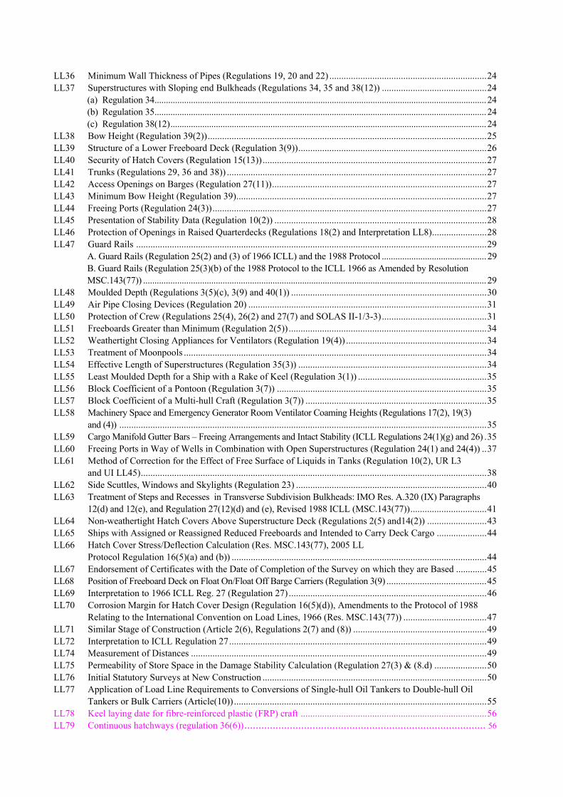
CONTENTS
Reference Table 1: ICLL Articles/Regulations and Corresponding IACS LL Interpretations ................................................5 Reference Table 2: IACS LL Interpretations Status ..................................................................................................... 7 LL1 Application (Article (4)) ............................................................................................................................... 11 LL2 Depth for Freeboard (Regulation 3(6)) ......................................................................................................... 11 LL3 Superstructure (Regulation 3(10)(b))............................................................................................................ 11 LL4 Details of Marking (Regulation 8)................................................................................................................ 11 LL5 Doors (Regulation 12) .................................................................................................................................. 11 LL6 Hatchways Closed by Weather Tight Covers of Steel or Other Equivalent Material Fitted With Gaskets
and Clamping Devices (Regulations 16 and 27(7)(c))...................................................................................... 11 Regulation 16 ........................................................................................................................................................ 11 Regulation 27(7)(c):.............................................................................................................................................. 12
LL7 Machinery Space Openings (Regulations 17(1), 26(1), 27(8) and 27(9)...................................................... 12 LL8 Miscellaneous Openings in Freeboard and Superstructure Decks (Regulation 18(2) and 18(3)) ................. 12
Regulation 18(2): .................................................................................................................................................. 12 Regulation 18(3): .................................................................................................................................................. 12
LL9 Deleted.......................................................................................................................................................... 13 LL10 Air Pipes (Regulation 20) ............................................................................................................................. 13 LL11 Scuppers, Inlets and Discharges (Regulation 22(1))..................................................................................... 13 LL12 Deleted.......................................................................................................................................................... 15 LL13 Freeing Ports (Regulations 24(1) and 24(5)) ................................................................................................ 15
Regulation 24(1) ................................................................................................................................................... 15 Regulation 24(5): .................................................................................................................................................. 15
LL14 Protection of the Crew (Regulation 25(2)) ................................................................................................... 15 LL15 Length of Superstructure (Regulations 34(1) and (2)).................................................................................. 15
Regulation 34(1): .................................................................................................................................................. 15 Regulation 34(2): .................................................................................................................................................. 15
LL16 Sheer (Regulation 38) ................................................................................................................................... 16 LL17 Minimum Bow Height (Regulations 39(1) and 39(2)) ................................................................................. 16 LL18 Freeboard Tables (Regulation 28) ................................................................................................................ 19
(a) Type A ships................................................................................................................................................... 19 (b) Type B ships................................................................................................................................................... 19
LL19 Form of Certificates (Article 18) .................................................................................................................. 19 LL20 Hatch Beams and Cover Stiffeners of Variable Cross Section (Regulations 15(4), 15(5), 15(6), 15(7) and 16).. 19 LL21 Cargo Ports or Similar Openings Below the Uppermost Load Line (Regulation 21(2)) .............................. 20 LL22 Position of the Inboard End of Discharges when Timber Freeboard is Assigned (Regulation 22(1))............. 20 LL23 Freeing Arrangement (Regulations 26(5), 27(7) and 36(1)(e)) .................................................................... 20
Regulation 27(7): Freeing Arrangements on Ships Having Reduced B Freeboard Assigned and Fitted with Bulwarks on the Freeboard Deck................................................................................................................. 20 Regulations 26(5) and 36(1)(e): Freeing Arrangements for Type A Ships and Type B Ships with Trunks...... 21
LL24 Negative Depth Correction (Regulation 31(3)) ............................................................................................ 21 LL25 Effective Length of Raised Quarterdeck (Regulation 35(4)) ........................................................................ 21 LL26 Continuous Hatchways as Trunk (Regulation 36) ........................................................................................ 21 LL27 Less than Standard Hatch Coamings on Trunks of Less than Standard Height (Regulation 36(4)) ............. 21 LL28 Deduction for Superstructures and Trunks (Regulations 37 and 38(12)) ..................................................... 22 LL29 Sheer Credit for Superimposed Superstructures (Regulations 38(5), 38(7) and 38(12)) .............................. 22
(a) Regulation 38(5): Superstructures Superimposed on a Complete Superstructure.......................................... 22 (b) Regulation 38(7): Superstructures Superimposed on a Forecastle or Poop (i.e. a Stepped Forecastle or Poop)..22
LL30 Sheer Allowance for Excess Height of Superstructure (Regulations 38(7) and 38(12)) .............................. 23 LL31 Deduction for Excess Sheer (Regulation 38(15)) ......................................................................................... 23 LL32 Special Requirements for Vehicle Ferries, Ro-Ro Ships and other Ships of Similar Type .......................... 23 LL33 Timber Freeboards for Ships Having Reduced Type B Freeboards Assigned (Regulations 45(2) and 45(3)) ......23 LL34 Freeboard for Lighters and Barges (Regulation 27(11) of 1966 ILLC)........................................................ 23 LL35 Stowage of Timber Deck Cargo on Ships Having Timber Freeboards Assigned (Regulations 44 and 45).. 24
LL36 Minimum Wall Thickness of Pipes (Regulations 19, 20 and 22) ..................................................................24 LL37 Superstructures with Sloping end Bulkheads (Regulations 34, 35 and 38(12)) ............................................24
(a) Regulation 34.................................................................................................................................................. 24 (b) Regulation 35.................................................................................................................................................. 24 (c) Regulation 38(12)........................................................................................................................................... 24
LL38 Bow Height (Regulation 39(2)).....................................................................................................................25 LL39 Structure of a Lower Freeboard Deck (Regulation 3(9))...............................................................................26 LL40 Security of Hatch Covers (Regulation 15(13))..............................................................................................27 LL41 Trunks (Regulations 29, 36 and 38)) .............................................................................................................27 LL42 Access Openings on Barges (Regulation 27(11))..........................................................................................27 LL43 Minimum Bow Height (Regulation 39).........................................................................................................27 LL44 Freeing Ports (Regulation 24(3))...................................................................................................................27 LL45 Presentation of Stability Data (Regulation 10(2)) .........................................................................................28 LL46 Protection of Openings in Raised Quarterdecks (Regulations 18(2) and Interpretation LL8).......................28 LL47 Guard Rails ...................................................................................................................................................29
A. Guard Rails (Regulation 25(2) and (3) of 1966 ICLL) and the 1988 Protocol .............................................. 29 B. Guard Rails (Regulation 25(3)(b) of the 1988 Protocol to the ICLL 1966 as Amended by Resolution MSC.143(77)) ....................................................................................................................................................... 29
LL48 Moulded Depth (Regulations 3(5)(c), 3(9) and 40(1)) ..................................................................................30 LL49 Air Pipe Closing Devices (Regulation 20) ....................................................................................................31 LL50 Protection of Crew (Regulations 25(4), 26(2) and 27(7) and SOLAS II-1/3-3)............................................31 LL51 Freeboards Greater than Minimum (Regulation 2(5)) ...................................................................................34 LL52 Weathertight Closing Appliances for Ventilators (Regulation 19(4)) ...........................................................34 LL53 Treatment of Moonpools ...............................................................................................................................34 LL54 Effective Length of Superstructures (Regulation 35(3)) ...............................................................................34 LL55 Least Moulded Depth for a Ship with a Rake of Keel (Regulation 3(1)) ......................................................35 LL56 Block Coefficient of a Pontoon (Regulation 3(7)) ........................................................................................35 LL57 Block Coefficient of a Multi-hull Craft (Regulation 3(7)) ............................................................................35 LL58 Machinery Space and Emergency Generator Room Ventilator Coaming Heights (Regulations 17(2), 19(3)
and (4)) ..........................................................................................................................................................35 LL59 Cargo Manifold Gutter Bars – Freeing Arrangements and Intact Stability (ICLL Regulations 24(1)(g) and 26) .35 LL60 Freeing Ports in Way of Wells in Combination with Open Superstructures (Regulation 24(1) and 24(4)) ..37 LL61 Method of Correction for the Effect of Free Surface of Liquids in Tanks (Regulation 10(2), UR L3
and UI LL45).................................................................................................................................................38 LL62 Side Scuttles, Windows and Skylights (Regulation 23) ................................................................................40 LL63 Treatment of Steps and Recesses in Transverse Subdivision Bulkheads: IMO Res. A.320 (IX) Paragraphs
12(d) and 12(e), and Regulation 27(12)(d) and (e), Revised 1988 ICLL (MSC.143(77))................................41 LL64 Non-weathertight Hatch Covers Above Superstructure Deck (Regulations 2(5) and14(2)) .........................43 LL65 Ships with Assigned or Reassigned Reduced Freeboards and Intended to Carry Deck Cargo .....................44 LL66 Hatch Cover Stress/Deflection Calculation (Res. MSC.143(77), 2005 LL
Protocol Regulation 16(5)(a) and (b)) ...........................................................................................................44 LL67 Endorsement of Certificates with the Date of Completion of the Survey on which they are Based .............45 LL68 Position of Freeboard Deck on Float On/Float Off Barge Carriers (Regulation 3(9) ..........................................45 LL69 Interpretation to 1966 ICLL Reg. 27 (Regulation 27) ...................................................................................46 LL70 Corrosion Margin for Hatch Cover Design (Regulation 16(5)(d)), Amendments to the Protocol of 1988
Relating to the International Convention on Load Lines, 1966 (Res. MSC.143(77)) ...................................47 LL71 Similar Stage of Construction (Article 2(6), Regulations 2(7) and (8)) ........................................................49 LL72 Interpretation to ICLL Regulation 27............................................................................................................49 LL74 Measurement of Distances ............................................................................................................................49 LL75 Permeability of Store Space in the Damage Stability Calculation (Regulation 27(3) & (8.d) ......................50 LL76 Initial Statutory Surveys at New Construction ..............................................................................................50 LL77 Application of Load Line Requirements to Conversions of Single-hull Oil Tankers to Double-hull Oil
Tankers or Bulk Carriers (Article(10))..........................................................................................................55 LL78 Keel laying date for fibre-reinforced plastic (FRP) craft ..............................................................................56 LL79 Continuous hatchways (regulation 36(6))..................................................................................... 56

5
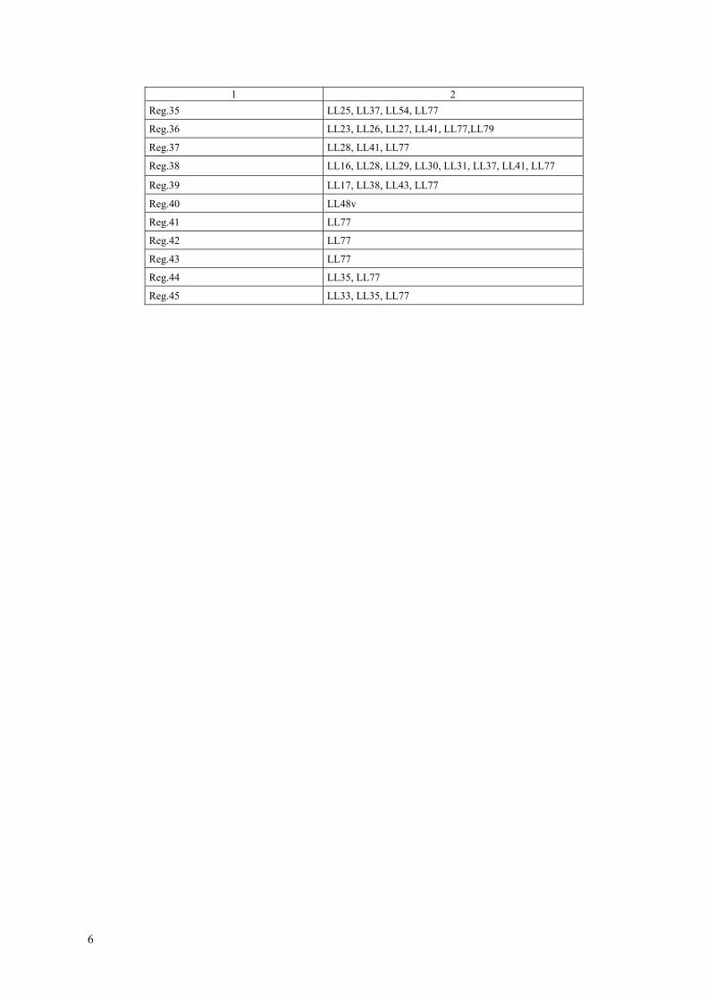
Reference table 1 ICLL articles/regulations and corresponding IACS LL interpretations
LL Protocol 1988, Regulation (Reg.) or ICLL Article (Art.) No. Related interpretation No.
1 2 Art.2 LL71, LL78
Art.4 LL1
Art. 10 LL77
Art.18 LL19, LL67
Art.19 LL67
Reg.1 LL77
Reg.2 LL51, LL64, LL71, LL77
Reg.3 LL2, LL3, LL39, LL48, LL55, LL56, LL57, LL68, LL77
Reg.4 LL77
Reg.5 LL77
Reg.6 LL77
Reg.7 LL77
Reg.8 LL4, LL75, LL77
Reg.9 LL77
Reg.10 LL45, LL61, LL77
Reg.11 LL77
Reg.12 LL5, LL77, UI SC220
Reg.13 LL77
Reg.14 LL64, LL77
Reg.15 LL20, LL40, LL77
Reg.16 LL6, LL20, LL66, LL70, LL77
Reg.17 LL7, LL58, LL77
Reg.18 LL8, LL46, LL77
Reg.19 LL36, LL52, LL58, LL77
Reg.20 LL10, LL36, LL49, LL77
Reg.21 LL21, LL77
Reg.22 LL11, LL22, LL36, LL77
Reg.23 LL12, LL62, LL77
Reg.24 LL13, LL44, LL59, LL60, LL77
Reg.25 LL14, LL47, LL50, LL77
Reg.26 LL7, LL23, LL50, LL59, LL77
Reg.27 LL6, LL7, LL23, LL34, LL42, LL50, LL63, LL65, LL69, LL72, LL75, LL77
Reg.28 LL18, LL77
Reg.29 LL41, LL77
Reg.30 LL77
Reg.31 LL24, LL77
Reg.32 LL77
Reg.33 LL77
Reg.34 LL15, LL37, LL77
6
1 2 Reg.35 LL25, LL37, LL54, LL77
Reg.36 LL23, LL26, LL27, LL41, LL77,LL79
Reg.37 LL28, LL41, LL77
Reg.38 LL16, LL28, LL29, LL30, LL31, LL37, LL41, LL77
Reg.39 LL17, LL38, LL43, LL77
Reg.40 LL48v
Reg.41 LL77
Reg.42 LL77
Reg.43 LL77
Reg.44 LL35, LL77
Reg.45 LL33, LL35, LL77

7
Reference table 2 IACS LL interpretations status
Interpretation Reference Adopted Submitted to IMO A
IMO approval
Submitted to governments Remarks
LL1 Application Art. 4 1968 1972 yes 1972 Rev. 1 2008 LL2 Depth for freeboard Reg. 3(6) 1968 1972 yes 1972 Rev. 1 2008 LL3 Superstructure Reg. 3(10)(b) 1968 1972 yes 1972 Rev. 1 2008 LL4 Details of marking Reg. 8 1968 1972 yes 1972 Rev. 1 2008 LL5 Doors Reg. 12 1968 1972 yes 1972 Rev. 1 2008 LL6 Hatchways closed by weathertight covers of steel or other equivalent material fitted with gaskets and clamping devices
Reg. 16&27(7)(c) Rev.1 July 2004 1972 yes 1972 Rev. 3 2008
LL7 Machinery space openings Reg. 17(1), 26(1), 27(8) and 27(9)
1968/Rev.1 Jun 2002 1972 yes 1972 Rev. 2 2008
LL8 Miscellaneous openings in freeboard and su-perstructure decks
Reg. 18(2) & 18(3) 1968 1972 yes 1972 Rev. 1 2008
LL9 DELETED LL10 Air pipes Reg. 20 1968 1972 yes 1972 Rev. 1 2008 LL11 Scuppers, inlets and discharges Reg. 22(1) Rev.2 1994 1972 yes 1972 Rev.3 1994 LL12 DELETED Deleted 2008 LL13 Freeing ports Reg. 24(1) & (5) 1968 1972 yes 1972 Rev. 1 2008 LL14 Protection of the crew Reg. 25(2) 1968 1972 yes 1972 Rev. 1 2008 LL15 Length of superstructure Reg. 34(1) & (2) 1968/Rev.2 July 2003 1972 yes 1972 Rev. 3 2008 LL16 Sheer Reg. 38 1968 1972 yes 1972 Rev. 1 2008 LL17 Minimum bow height Reg. 39 Corr.2 Oct 2007 1972 not yet 1972 Rev. 1 2008 LL18 Freeboard tables Reg. 28 1968 1972 yes 1972 Rev. 1 2008 LL19 Form of certificates Art. 18 1972 1972 yes 1972 Rev. 1 2008 LL20 Hatch beams and cover stiffeners of variable cross section
Reg. 15(4), (5), (6), (7) & 16 1972 1972 yes 1972 Rev. 1 2008
LL21 Cargo ports or similar openings below the uppermost load line
Reg. 21(2) 1972 1972 yes 1972 Rev. 1 2008
LL22 Position of the inboard end of discharges when timber freeboard is assigned
Reg. 22(1) 1972 1972 yes 1972 Rev. 1 2008
LL23 Freeing arrangement Reg. 26(5), 27(7) & 36(1) (e) 1972 1972 yes 1972 Rev. 1 2008 LL24 Negative depth correction Reg. 31(3) 1972 1972 yes 1972 Rev. 1 2008

8
Interpretation Reference Adopted Submitted to IMO A
IMO approval
Submitted to governments Remarks
LL25 Effective length of raised quarterdeck Reg. 35(4) 1972 1972 yes 1972 Rev. 1 2008 LL26 Continuous hatchways as trunk Reg. 36 Rev.1 1983 1983 yes Rev. 2 2008 LL27 Less than standard hatch coamings on trunks of less than standard height
Reg. 36(4) 1972 1972 yes 1972 Rev. 1 2008
LL28 Deduction for superstructures and trunks Reg. 37 & 38(12) 1972 1972 yes 1972 Rev. 1 2008 LL29 Sheer credit for superimposed superstructures Reg. 38(5), (7) & (12) Rev.1 1983 1983 yes Rev. 2 2008 LL30 Sheer allowance for excess height of super-structure
Reg. 38(7) & (12) 1972 1972 yes 1972 Rev. 1 2008
LL31 Deduction for excess sheer Reg. 38(15) 1972 1972 yes 1972 Rev. 1 2008 LL32 Special requirements for vehicle ferries, ro-ro ships and other ships of similar type
Withdrawn Oct 2007 1972 1972 yes partly 1972 LL32(b) Noted at IMO as a safety re-quirement but out-side the scope of LLC 1966. Retained for IACS purposes
LL33 Timber freeboards for ships having reduced Type ‘B’ freeboards assigned
Reg. 45(2) & 45(3) 1972 1972 yes 1972 Rev. 1 2008
LL34 Freeboard for lighters and barges Reg. 27(11) 1972 1972 yes 1972 Corr. 1 2008 LL35 Stowage of timber deck cargo on ships having timber freeboards assigned
Reg. 44 & 45 1972 1972 yes 1972 Corr. 1 2008
LL36 Minimum wall thickness of pipes Reg. 19, 20 & 22 Rev.1 1978 1978 yes 1978 Rev. 2 July 2008 LL37 Superstructures with sloping end bulkheads Reg. 34, 35 & 38(12) Rev.1 1983/Corr. 1996 1983 yes Rev. 2 2008 LL38 Bow height Reg. 39(2) Corr.1 June 2006 1983 yes Rev. 2 2008 LL39 Structure of a lower freeboard deck Reg. 3(9) 1977 1978 yes 1978 Rev. 1 2008 LL40 Security of hatch covers Reg. 15(13) Rev.1 1980 1980 yes 1980 Rev. 2 2008 LL41 Trunks Reg. 29, 36 & 38 1978 1978 yes 1978 Rev. 1 2008 LL42 Access openings on barges Reg. 27(11) 1978 1978 yes 1978 Rev. 1 2008 LL43 Minimum bow height Reg. 39 1978 1978 yes 1978 Rev. 1 2008 LL44 Freeing ports Reg. 24(3) 1978 1978 yes 1978 Rev. 1 2008 LL45 Presentation of stability data Reg. 10(2) Rev.1 1984 1986 Rev. 2 2008 LL46 Protection of openings in raised quarter decks Reg. 18(2) Interp. LL8 Rev.1 1980/ Rev.2 1997 1980 yes 1980 Rev. 3 2008 LL47 Guard rails Reg. 25 Corr.1 Oct 2007 1980 yes 1980 Rev. 3 2008 LL48 Moulded depth and freeboard calculation Reg. 3(5) (c), 3(9) & 40(1) Rev.1 1983 Rev.1 1983 yes Rev. 2 2008 LL49 Air pipe closing devices Reg. 20 1980 1980 yes 1980 Rev. 1 2008

9
Interpretation Reference Adopted Submitted to IMO A
IMO approval
Submitted to governments Remarks
LL50 Protection of crew Reg. 25(4), 26(2) & 27(7) SOLAS II-1/3.3
Rev. 4.1 Oct 98 Rev.4 1998 yes Rev. 5 2008
LL51 Freeboards greater than minimum Reg. 2(5) Rev.1 1986 Rev.2 1997 yes Rev. 2 2008 LL52 Weathertight closing appliances for ventila-tors
Reg. 19(4) 1983 1983 yes Rev. 1 2008
LL53 Treatment of moonpools 1987 1987 Rev. 1 2008 LL54 Effective length of superstructures Reg. 35(3) 1989 Rev. 1 2008 LL55 Least Moulded Depth for a ship with a Rake of Keel
Reg. 3(1) 1993 Rev. 1 2008
LL56 Block Coefficient of a Pontoon Reg. 3(7) 1993 Rev. 1 2008 LL57 Block Coefficient of a Multi-hull Craft Reg. 3(7) 1996 Rev. 1 2008 LL58 Machinery space and emergency generator room ventilator coaming heights
Reg. 17(2), 19(3) & 19(4) 1997 Rev. 1 2008
LL59 Cargo manifold gutter bars – freeing ar-rangements and intact stability
Reg 24(1)g Reg. 26 Rev.1 Dec 2007
LL60 Freeing ports in way of wells in combination with open superstructures
Reg.24(1) &24 (4) 1997, Corr.1 April 1998 Rev. 1 2008
LL61 Method of correction for the effect of free surface of liquids in tanks (Regulation 10(2), UR L3 and UI LL45)
Reg. 10(2) UR L3 UI LL45
1997 Rev. 1 2008
LL62 Side Scuttles, Windows and Skylights Reg. 23 1997 Rev. 1 2008 Corr. 1 August 2010
LL63 Treatment of steps and recesses in transverse subdivision bulkheads: IMO Res. A.320
Reg. 27(12)(d)(e) Rev.1 July 2008
LL64 Non-Weathertight Hatchcovers above Super-structure Deck
Reg. 2(5) & 14(2) Rev.5 July 2008
LL65 Ships with assigned or reassigned reduced freeboards and intended to carry deck cargo
Reg. 27 Rev.2 July 2008
LL66 Hatch Cover Stress/ Deflection Calculation (Res. MSC.143(77), 2005 LL Protocol Regulation 16(5) (a) & (b))
Reg. 16(5)(a) & (b) Oct 2003
LL67 Endorsement of Certificates with the Date of Completion of the Survey on which they are Based
Art. 18, Art. 19 Rev.1 Nov 2005
LL68 Position of Freeboard Deck on Float On/Float Off Barge Carriers (Regulation 3(9))
Reg. 3(9) Rev. 1 July 2008

10
Interpretation Reference Adopted Submitted to IMO A
IMO approval
Submitted to governments Remarks
LL69 Interpretation to 1966 ICLL Reg. 27 Reg. 27 Rev. 1 July 2008 LL70 Corrosion Margin for Hatch Cover Design (FAQ)
Reg. 16(5)d 1988 Prot. Jan 2005
LL71 Similar stage of Construction Art. 2(6) Reg. 2(7) & (8) 1988 Prot.
Rev. 1 July 2008
LL72 Interpretation to ICLL Regulation 27 Reg. 27(3) Sept 2005 LL73 under development LL74 Measurement of distances Aug 2008 LL75 Permeability of Store Spaces in the Damage Stability Calculation
Reg. 27(3) Reg. 27(8.d) 1988 Prot
Rev. 1 Mar 2009
LL76 Initial Statutory Surveys at New Construction Corr. 1 July 2010 LL 77 Application of Load Line Requirements to Conversions of Single-hull Oil Tankers to Double-hull Oil Tankers or Bulk Carriers
Art. 10
Dec 2011
LL 78 Keel laying date for fibre-reinforced plastic (FRP) craft.
Art. 4 Mar 2013 (Corr.1 Jan 2014)
LL 79 Continuous hatchways Reg. 36(6) 1988 Prot July 2014

11
LL1 APPLICATION (ARTICLE (4)):
Even where the increase in draught is only of the order of 1 in or 2 in there should be no relaxation from the condition that existing ships comply with all the requirements. Footnote: This UI is also applicable to the revised Article 4 of the 1966 Convention as modified by its 1988 Protocol.
LL2 DEPTH FOR FREEBOARD (REGULATION 3 (6)):
The correction for thickness of sheathing on the exposed freeboard deck T(L-S)/L is applicable only when deck is completely sheathed between superstructures. In other cases the correction should be Tl/L, where l = length of sheathed area which extends from side to side. Only wood sheathing should be con-sidered. Footnote: This UI is also applicable to Regulation 3(6) of the 1988 Protocol. LL3 SUPERSTRUCTURE (REGULATION 3(10)(B)):
A bridge or poop shall not be regarded as enclosed unless access is provided for the crew starting from any point on the uppermost complete exposed deck or higher to reach machinery and other working spaces inside these superstructures by alternative means which are available at all times when bulkhead openings are closed. Footnote: This UI is also applicable to Regulation 3(10)(b) of the 1988 Protocol.
LL4 DETAILS OF MARKING (REGULATION 8):
'Permanently marked' is considered to include welding of the marks on the sides of the ship provided the usual precautions as to material, electrodes, etc. are observed. Footnote: This UI is also applicable to Regulation 8 of the 1988 Protocol and the revised 1988 Protocol.
LL5 DOORS (REGULATION 12):
(a) Doors should generally open outwards to provide additional security against the impact of the sea. Doors which open inwards are to be especially approved.
(b) Portable sills should be avoided. However, in order to facilitate the loading/unloading of heavy spare parts or similar, portable sills may be fitted on the following conditions: (i) They must be installed before the ship leaves port. (ii) Sills are to be gasketed and fastened by closely spaced through bolts. (iii) Whenever the sills are replaced after removal, the weathertightness of the sills and the related doors
must be verified by hose testing. The dates of removal, replacing and hose testing shall be recorded in the ship's log book.
Footnotes: 1. This UI is also applicable to Regulation 12 of 1988 Protocol. 2. Paragraph (b)(iii) of this UI is also applicable to Regulation 12 of the revised 1988 Protocol.
LL6 HATCHWAYS CLOSED BY WEATHERTIGHT COVERS OF STEEL OR OTHER EQUIVALENT MATERIAL FITTED WITH GASKETS AND CLAMPING DEVICES (REGULATIONS 16 AND 27(7)(c)):
Regulation 16:
Where hatchways are fitted with coamings of standard height, no extra strengthening (beyond what is required in the Load Line Convention) shall be required for covers loaded with cargo, even if dense cargo, provided the load does not exceed 1.75 ton/m2 (in position 1)*.

12
Regulation 27(7)(c):
No extra strengthening is recommended for hatchway covers on vessels* which are assigned free-boards less than those based on Table B, except for flush hatchway covers which are fitted on the free-board deck forward of the quarter length, in which case the section modulus and the moment of interia shall be increased 15% over that required by Regulation 16. * Bulk Carriers: For the hatch covers on Bulk Carriers, as defined in UR Z1 1.2.2, contracted for construction on or after 1 July
1998, the hatch cover load and strength requirements are to be in accordance with IACS Unified Requirement S21, "Evalua-tion of Scantlings of Hatch Covers of Bulk Carrier Cargo Holds".
Footnote: This UI is also applicable to Regulation 16 and 27(8)(c) of the 1988 Protocol. Note: The "contracted for construction" date means the date on which the contract to build the vessel is signed between the prospective owner and the shipbuilder. For further details regarding the date of "contract for construction", refer to IACS Procedural Re-quirement (PR) No. 29.
LL7 MACHINERY SPACE OPENINGS (REGULATIONS 17(1), 26(1), 27(8) AND 27 (9)):
Where casings are not protected by other structures, double doors should be required for type A or type B ships assigned freeboards less than those based on Table B1. An inner sill of 230 mm in conjunc-tion with the outer sill of 600 mm is recommended. Footnotes: 1. This UI is also applicable to Regulations 17(1), 26(1), 27(9) and 27(10) of the 1988 Protocol; 2. "Based on Table B" means without any reduction in accordance with Regulation 27(8) or (9) of the 1966 ICLL or Regula-
tion 27(9) or (10) of the 1988 Protocol.. Note: Changes introduced in Rev. 1 are to be uniformly implemented by IACS Members and Associates from 1 January 2003.
LL8 MISCELLANEOUS OPENINGS IN FREEBOARD AND SUPERSTRUCTURE DECKS (REGULATION 18 (2) & 18 (3)):
Regulation 18 (2): (a) Only those doorways in deckhouses leading to or giving access to companionways leading below,
need to be fitted with doors in accordance with Regulation 12. (b) Alternatively, if stairways within a deckhouse are enclosed within properly constructed companion-
ways fitted with doors complying with Regulation 12, the external door need not be watertight. (c) Where an opening in a superstructure deck or in the top of a deckhouse on the freeboard deck which
gives access to a space below the freeboard deck or to a space within an enclosed superstructure is protected by a deckhouse, then it is considered that only those side scuttles fitted in spaces which give direct access to an open stairway need be fitted with deadlights in accordance with Regulation 23. A cabin is considered to provide adequate protection against the minimal account of water which will enter through a broken side scuttle glass fitted on the second tier.
Regulation 18 (3):
In the application of Regulation 18 it is understood that: (i) where access is provided from the deck as an alternative to access from the freeboard deck in accor-
dance with Regulation 3 (10) (b) then the height of sills into a bridge or poop should be 380 mm. The same consideration should apply to deckhouses on the freeboard deck;
(ii) where access is not provided from above, the height of the sills to doorways in a poop bridge or deckhouse on the freeboard deck should be 600 mm;
(iii) where the closing appliances of access openings in superstructures and deckhouses are not in accor-dance with Regulation 12, interior deck openings are to be considered exposed, i.e. situated in the open deck.
Footnotes: 1. This UI is also applicable to Regulation 18(2) and 18(3) of the 1988 Protocol. 2. Paragraphs 1 (c) and 2 (ii) of this UI are also applicable to Regulation 18(2) and (6) of the revised 1988 Protocol respectively.

13
LL9 DELETED
LL10 AIR PIPES (REGULATION 20):
For ships assigned timber freeboards the air pipes should be provided with automatic closing appliances. Footnote: This UI is also applicable to Regulation 20 of the 1988 Protocol.
LL11 SCUPPERS, INLETS AND DISCHARGES (REGULATION 22 (1)):
It is considered that an acceptable equivalent to one automatic non-return valve with a positive means of closing from a position above the freeboard deck would be one automatic non-return valve and one sluice valve controlled from above the freeboard deck.
Where two automatic non-return valves are required, the inboard valve must always be accessible un-der service condition, i.e., the inboard valve should be above the level of the tropical load water line. If this is not practicable, then, provided a locally controlled sluice valve is interposed between the two automatic non-return valves, the inboard valve need not to be fitted above the LWL.
Where sanitary discharges and scuppers lead overboard through the shell in way of machinery spaces, the fitting to shell of a locally operated positive closing valve, together with non-return valve inboard, is considered to provide protection equivalent to the requirements of Regulation 22 (1).
It is considered that the requirements of Regulation 22 (1) for non-return valves are applicable only to those discharges which remain open during the normal operation of a vessel. For discharges which must necessarily be closed at sea, such as gravity drains from topside ballast tanks, a single screw down valve operated from the deck is considered to provide efficient protection.
The inboard end of a gravity discharge which leads overboard from an enclosed superstructure or space is to be located above the water line formed by a 5 degree heel, to port or starboard, at a draft cor-responding to the assign summer freeboard.
It is considered that the position of the inboard end of discharges should be related to the timber summer load waterline when timber freeboard is assigned.
Refer to the attached Table for the acceptable arrangements of scuppers, inlets, and discharges. For garbage chutes it is considered that an acceptable equivalent to the non-return valve with a posi-
tive means of closing from a position above the freeboard deck would be two gate valves controlled from the working deck of the chute. The lowest gate valve should, in addition, be controlled from a position above the freeboard deck. An interlock system between the two valves should be arranged.
It is recommended that the inboard end be located above the waterline formed by an 8.5 degree heel, to port or starboard, at a draft corresponding to the assigned summer freeboard, but not less than 1000 mm above the summer waterline.
Where the inboard end of the garbage chute exceeds 0.01L above the summer waterline, valve control from the freeboard deck is not required, provided the inboard gate valve is always accessible under ser-vice conditions.
The distance between the two gate valves should be adequate to allow the smooth operation of the in-terlock system.
Alternatively, the upper gate valve may be replaced by a hinged weathertight cover at the inboard end of the chute together with a discharge flap which replaces the lower gate valve.
The cover and flap are to be arranged with an interlock so that the discharge flap cannot be operated until the hopper cover is closed.
The chute is to be constructed of material of substantial thickness up to, and including, the cover. The gate valve(s) controls and/or hinged cover are to be clearly marked: "Keep closed when not in use". Where the inboard end of a garbage chute is below the margin line in a passenger ship, or the critical
(crucial) waterline of a cargo ship of more than 100 m in length then: (i) the inboard end hinged cover/valve is to be watertight; (ii) the valve is to be a screw-down non-return valve fitted in an easily accessible position above the
deepest subdivision load line; (iii) the screw-down non-return valve is to be controlled from a position above the bulkhead deck and
provided with open/shut indicators. The valve control is to be clearly marked: "Keep closed when not in use".

14
Where plastic pipes are used for sanity discharges and scuppers, they are also subject to the require-ments of the Table, and the valve at the shell is to be operated from outside the space in which the valve is located.
Where such plastic pipes are located below the summer waterline (timber summer load waterline), the valve is to be operated from a position above the freeboard deck.
The portion of discharge line from the shell to the first valve as well as shell fittings and valves shell be of steel, bronze or other approved ductile material.
The approval of plastic piping in any location will be subject to the consideration of strength and fire hazards involved with special reference to penetrations through bulkheads, decks or other significant compartment boundaries. Attention must also be paid to valid fire technical regulations.
Footnote: This UI is also applicable to Regulation 22(1) of the 1988 Protocol.
15
LL12 DELETED
LL13 FREEING PORTS (REGULATIONS 24 (1) AND 24 (5)):
Regulation 24 (1)
On a flush deck ship with a substantial deckhouse amidships, it is considered that the deckhouse pro-vides sufficient break to form two wells and that each could be given the required freeing port area based upon the length of the 'well'. It would not then be allowed to base the area upon 0,7L.
In defining a substantial deckhouse it is suggested that the breadth of the deckhouse should be at least 80% of the beam of the vessel, and that the passageways along the side of the ship should not exceed 1,5 m (4.9 ft) in width.
Where a screen bulkhead is fitted completely across the vessel, at the forward end of a midship deck-house, this would effectively divide the exposed deck into wells and no limitation on the breadth of the deckhouse is considered necessary in this case.
It is considered that wells on raised quarterdecks should be treated as previously, i.e. as being on free-board decks.
Regulation 24 (5):
With zero or little sheer on the exposed freeboard deck or an exposed superstructure deck it is consid-ered that the feeling port area should be spread along the length of the well. Footnote: This UI is also applicable to Regulation 24(1) and 24(5) of the 1988 Protocol.
LL14 PROTECTION OF THE CREW (REGULATION 25 (2)):
A guard rail should also be required for first tier deckhoused and for superstructures' ends. Footnote: This UI is also applicable to Regulation 25(2) of the 1988 Protocol and the revised 1988 Protocol.
LL15 LENGTH OF SUPERSTRUCTURE (REGULATIONS 34 (1) AND 34 (2)):
Regulation 34(1):
Where a superstructure bulkhead is recessed, the effective length of the superstructure shall be re-duced by an amount equivalent in area to the area of the recess related to the breadth of the ship at the mid-length of the recess.
Where the recess is unsymmetrical about the centre line, the largest portion of the recess shall be considered as applying to both sides of the ship.
It is considered that such a recess need not be decked over. Where a cargo hatchway, complying with the requirements of regulation 16 and having a coaming
height that extends above the level of the superstructure deck, is fitted in the recess and covering the whole area of the recess, the hatchway may be taken into account as forming a part of the superstructure, and the effective length of the superstructure need not be reduced by the amount equivalent in area to the area of the recess.
The hatchway coaming height shall be in accordance with Regulation 16(1), measured from the su-perstructure deck level.
Regulation 34(2):
Where there is an extension to a superstructure, which extension has a breadth on each side of the centre line at least 30% of the breadth of the ship, the effective length of the superstructure may be in-creased by considering an equivalent superstructure bulkhead in the form of a parabola. This parabola should extend from the extension at the centre line and pass through the junction of the actual superstruc-ture bulkhead with the sides of the extension and extend to the sides of the ship. This parabola should be completely contained within the boundary of the superstructure and its extensions.
16
If the superstructure is set-in from the side, up to the limit allowed under Regulation 3 (10), the equivalent bulkhead should be calculated on the basis of the actual breadth of the superstructure (not the breadth of the ship). Footnotes: 1. This UI is also applicable to Regulation 34(1) and 34(2) of the 1988 Protocol. 2. Changes introduced in Rev.2 (July 2003) are also applicable to regulation 34(1) of the revised 1988 Protocol. Note: Changes introduced in Rev.2 (July 2003) are to be uniformly implemented by IACS Members and Associates from 1 January 2004.
LL16 SHEER (REGULATION 38):
Where the height of a superstructure is less than standard, paragraph 12 may be applied except that the superstructure deck shall not be less than the minimum height of the superstructure above the virtual shear curve at any point.
For this purpose y shall be taken as the difference between the actual and minimum height of the su-perstructure at the end of sheer. Footnote: This UI is also applicable to Regulation 38 of the 1988 Protocol.
LL17 MINIMUM BOW HEIGHT (REGULATIONS 39(1) AND (2)): When a ship built on or after 21 July 1968 is arranged to suit exceptional operational requirements
such that the forecastle and/or sheer forward do not meet the provisions of paragraphs (1) and (2) of Regulation 39 of the 1966 ICLL, the increase of calculated summer freeboard may, with the concurrence of the Administration, be determined in the following ways: Nomenclature
00 ≥ΔE Bow height penalty. =minS sfbdH −min
minH Minimum bow height calculated according to paragraph (1) of this Regulation
sfbd Summer freeboard Ld 15.0≤ Extent of sheer (measured from FP). LlF 07.0≤ Mean covered length of forecastle.
h Height of forecastle measured at FP from zero sheer line. FPS Actual sheer measured at FP.
BHDS Actual sheer in way of forecastle bulkhead. 2
min1 15.015.0
⎟⎠⎞
⎜⎝⎛ −
=L
lLSS F Theoretical sheer in way of forecastle bulkhead corresponding to Smin.
2
1 15.015.0
⎟⎠⎞
⎜⎝⎛ −
=L
lLhS F Theoretical sheer in way of forecastle bulkhead corresponding to h.
a) Where no forecastle is fitted and the sheer forward extends less than 0.15L from fore perpendicular (FP):
015.0min0 ≥−=Δ
LdSSE FP
min5.10 SSFP ≤≤

17
b) Where there is no sheer on the forward part of the freeboard deck, and the forecastle length is less
than 0.07L from FP:
007.0min0 ≥−=Δ
Ll
hSE F
min5.10 Sh ≤≤
The height of the forecastle at the bulkhead position shall not be less than the ordinate, at that point,
of a parabolic sheer curve having an ordinate Smin at the forward perpendicular and extending aft for a distance of 0.15L from the forward perpendicular. c) Where the sheer forward extends less than 0.15L and the length of forecastle is less than 0.07L from
FP: (i) minmin 5.1 ShS ≤≤
15.10 SSBHD ≤≤
0)15.0
1)(07.0
1(1min
min0 ≥−
−−−=Δ
F
FBHDF
lLld
SS
Ll
ShSE

18
Condition:
⎪⎪⎭
⎪⎪⎬
⎫
−−
−
−
)15.0
1(
)07.0
1(
1
min
F
FBHD
F
lLld
SS
Ll
Sh
not to be taken negative (less than zero)
The height of the forecastle at bulkhead must satisfy the same conditions as in subparagraph (b) of this paragraph.
(ii) minSh ≤
25.10 SSBHD ≤≤
0)15.0
1)(07.0
1()(2
min0 ≥−
−−−+−=Δ
F
FBHDF
lLld
SS
Ll
hhSE
Condition:
⎪⎪⎭
⎪⎪⎬
⎫
−−
−
−
)15.0
1(
)07.0
1(
2 F
FBHD
F
lLld
SS
Ll
not to be taken negative (less than zero)
The height of the forecastle at bulkhead position shall not be less than the ordinate, at that point, or a parabolic sheer curve having an ordinate h at the forward perpendicular and extending aft for a distance of 0.15L from the forward perpendicular.
(d) In general, this interpretation should be applied to existing ships only. However, to suit exceptional operational requirements, and upon the special consideration by the Administration, the provision of this interpretation may also be applied to new ships.
Note: This UI may also be applied to Regulation 39(1) and 39(2) of the 1988 Protocol and revised 1988 Protocol upon the special con-sideration by the Administration.
19
LL18 FREEBOARD TABLES (REGULATION 28):
(a) Type A ships (i) Freeboards for Type A ships with lengths between 365 m and 400 m shall be determined by the
following formula: f = 221 + 16.10L – 0.02L2
where: f is the freeboard in [mm] L is the length as defined in Regulation 3(1).
(ii) Freeboards for Type A ships with lengths of 400 m and above shall be the constant value, 3460 mm.
(b) Type B ships (i) Freeboards for Type B ships with lengths between 365 m and 400 m shall be determined by the
following formula: f = – 587 + 23L – 0.0188L2
where: f is the freeboard in [mm] L is the length as defined in Regulation 3(1).
(ii) Freeboards for Type B ships with lengths of 400 m and above shall be the constant value, 5605 mm.
Footnote: This UI is also applicable to Regulation 28 of the 1988 Protocol and the revised 1988 Protocol.
LL19 FORM OF CERTIFICATES (ARTICLE 18):
It is recommended that the model form of certificates given in Annex III of the Load Line Convention should be strictly adhered to and any deviations from this pattern should be avoided. Footnote: This UI is also applicable to Article 18 of the 1988 Protocol and the revised 1988 Protocol.
LL20 HATCH BEAMS AND COVER STIFFENERS OF VARIABLE CROSS SECTION (REGULATIONS 15(4), 15(5), 15(6), 15(7) AND 16):
To avoid stresses and deflections exceeding those given in the above Regulations along construction elements of variable cross section, the required section modulus calculated as for constriction elements of constant cross section is to be increased by a factor K expressed by:
4.078.02.31
+−−
+=γαK
where: α= l1/l0, γ= W1 /W0.
The value of factor K obtained by the formula is not to be less than unity. l1, l0, Wl and W0 are indicated on the sketch below:

20
The moment of inertia is likewise to be increased by the factor C expressed by:
ββα34.0
181 3
+
−+=C
where: 01 / ll=α , 01 / II=β .
The value factor of C obtained by the formula is not to be less than unity. I1 and I0 are indicated on the sketch above.
The use of the above formulae is limited to the determination of the strength of hatch beams and cov-ers in which abrupt changes in the section of the face material do no occur along the length of the beam or cover end. Footnote: This UI is also applicable to Regulations 15(4), 15(5), 15(6), 15(7) and 16 of the 1988 Protocol.
LL21 CARGO PORTS OR SIMILAR OPENINGS BELOW THE UPPERMOST LOAD LINE (REGULATION 21(2)):
It is recommended that cargo ports or similar openings may be accepted submerged provided the safety of the ship is in no way impaired. It is considered that the fitting of a second door of equivalent strength and watertightness is one acceptable arrangement. In that case leakage detection device should be provided in the compartment between the two doors. Further, drainage of this compartment to the bilges controlled by an easily accessible screw down valve, should be arranged. The outer door should preferably open outwards. Footnote: This UI is also applicable to Regulation 21(2) of the 1988 Protocol.
LL22 POSITION OF THE INBOARD END OF DISCHARGES WHEN TIMBER FREEBOARD IS ASSIGNED (REGULATION 22(1)):
It is considered that the position of the inboard end of discharges should be related to the timber summer load waterline when timber freeboard is assigned. Footnotes: 1. This UI is also applicable to Regulation 22(1) of the 1988 Protocol. 2. This UI is also applicable to Regulation 22-1 of the revised 1988 Protocol.
LL23 FREEING ARRANGEMENT (REGULATIONS 26(5), 27(7) AND 36(1)(e)):
REGULATION 27(7): FREEING ARRANGEMENTS ON SHIPS HAVING REDUCED B FREEBOARD ASSIGNED AND FITTED WITH BULWARKS ON THE FREEBOARD DECK
For Type B ships with freeboards reduced by not more than 60% of the difference between B and A tables there shall be freeing port area in the lower part of the bulwarks equal to at least 25% of the total area of the bulkwarks. The upper edge of the sheer strake shall be kept as low as possible.
21
REGULATIONS 26(5) AND 36(1)(e): FREEING ARRANGEMENTS FOR TYPE A SHIPS AND TYPE B SHIPS WITH TRUNKS
It is considered that a freeing port area, in the lower part of the bulwarks, of 33% of the total area of the bulwarks provides the 'other effective freeing arrangements' mentioned in Regulation 26, and may be considered equivalent to the 50% open rails in way of trunks required by Regulation 36(1)(e). Footnotes: 1. This UI is also applicable to Regulations 26(5), 27(8) and 36(1)(e) of the 1988 Protocol. 2. This UI is also applicable to Regulation 27(8) of the revised 1988 Protocol.
LL24 NEGATIVE DEPTH CORRECTION (REGULATION 31(3)): When the height of a superstructure, raised quarterdeck or trunk is less than the corresponding stan-
dard height, it is recommended that the calculated reduction be corrected in the ratio of the height of the actual superstructure, raised quarterdeck or trunk to the applicable standard height as defined in Regula-tion 33. Footnote: This UI is also applicable to Regulation 31(3) of the 1988 Protocol and the revised 1988 Protocol.
LL25 EFFECTIVE LENGTH OF RAISED QUARTERDECK (REGULATION 35(4)): It is recommended that the maximum effective length of 0.6L of a raised quarterdeck which is stipulated
by Regulation 35(4), is to be measured from the after perpendicular even where a poop is fitted in conjunc-tion with the raised quarterdeck. Footnote: This UI is also applicable to Regulation 35(4) of the 1988 Protocol
LL26 CONTINUOUS HATCHWAYS AS TRUNK (REGULATION 36):
It is recommended that continuous hatchways may be treated as a trunk in the freeboard computation provided Regulation 36 is complied with in all respects.
The trunk deck stringer referred to in Regulation 36(1)(b) may be fitted outboard of the trunk side bulkhead in association with the following: (i) The stringer so formed is to provide a clear walkway of at least 450 mm in width on each side of the
ship; (ii) The stringer is to be of solid plate efficiently supported and stiffened. (iii) The stringer is to be as high above the freeboard deck as practicable. In the freeboard calculation,
the trunk height is to be reduced by at least 600 mm or by the actual difference between the top of the trunk and the stringer, whichever is greater;
(iv) Hatch cover securing appliances are to be accessible from the stringer or walkway; (v) The breadth of the trunk is to be measured between the trunk side bulkheads; (vi) Regulation 36 is to be complied with in all other respects. Footnote: This UI is also applicable to Regulation 36 of the 1988 Protocol.
LL27 LESS THAN STANDARD HATCH COAMINGS ON TRUNKS OF LESS THAN STANDARD HEIGHT (REGULATION 36(4)):
In the case where trunk height is less than standard and the trunk hatch coamings are also of less than standard height, or omitted entirely, doubt may arise whether the trunk hatchways are located in position 1 or position 2 and, consequently, about the reduction to be made in the actual trunk height. It is consid-ered that in these cases the reduction from the actual height of trunk on account of insufficient hatch coaming height shall be taken as the difference between 600 mm and the actual height of coaming, or 600 mm if no hatch coamings are fitted. Reduction in the actual height of trunk shall not be required in cases where only small hatches with less than standard height are fitted in the trunk deck for which dis-pensation from the requirement of standard coaming height may be given. Footnote: This UI is also applicable to Regulation 36(4) of the 1988 Protocol.

22
LL28 DEDUCTION FOR SUPERSTRUCTURES AND TRUNKS (REGULATIONS 37 AND 38(12)):
For the purpose of applying the table 'Percentage of Deduction for Type B ships' in Regulation 37(2) it is considered that any detached superstructure abaft midship whose after bulkhead is located 0.05L or more forward of the after perpendicular may be treated as a detached bridge.
A superstructure whose after bulkhead is located within 0.05L from the after perpendicular shall not qualify as a detached bridge.
Any excess in the height of such a superstructure, which does not extend to the after perpendicular, cannot be regarded as contributing to the sheer allowance contemplated in Regulation 38(12). Footnote: This UI is also applicable to Regulations 37 and 38(12) of the 1988 Protocol.
LL29 SHEER CREDIT FOR SUPERIMPOSED SUPERSTRUCTURES (REGULATIONS 38(5), 38(7) AND 38(12)):
(A) REGULATION 38(5): SUPERSTRUCTURES SUPERIMPOSED ON A COMPLETE SUPERSTRUCTURE.
In applying Regulation 38(5) (sheer on a complete superstructure ship) where there is an enclosed poop or forecastle superimposed on a complete superstructure, sheer credit shall be allowed for such a poop or forecastle, according to the method of Regulation 38(12) as shown in Fig 1.
(B) REGULATION 38(7): SUPERSTRUCTURES SUPERIMPOSED ON A FORECASTLE
OR POOP (I.E. A STEPPED FORECASTLE OR POOP).
In applying Regulation 38(7) and 38(12) where a poop or forecastle consists of two layers, the method shown in Fig 2 shall be used:

23
In the above the following definitions apply: Z is as per Reg. 38(5). Zv is the end ordinate of a virtual standard parabolic curve taken through the point "X". If Zv is greater than (Z+h), the end ordinate shall be (Z+h), in which case point "X" shall be disregarded and curve (2) not taken into account.
When the length of the first tier superstructure is greater than 0.5L, the virtual standard parabolic curve shall commence at amidships as indicated in Fig 1. Footnote: This UI is also applicable to Regulations 38(5), 38(7) and 38(12) of the 1988 Protocol.
LL30 SHEER ALLOWANCE FOR EXCESS HEIGHT OF SUPERSTRUCTURE (REGULATIONS 38(7) AND 38(12)):
As Regulation 38(7) and (12) does not refer to a raised quarter deck it is recommended that credit un-der this paragraph be given for this type of superstructure only when the height of the raised quarterdeck is greater than the standard height of 'other superstructures' as defined in Regulation 33, and only for the amount by which the actual height of the raised quarterdeck exceeds that standard height. Footnote: This UI is also applicable to Regulations 38(7) and 38(12) of the 1988 Protocol.
LL31 DEDUCTION FOR EXCESS SHEER (REGULATION 38(15)):
Since no stipulation is made as to the height of the superstructure referred to in Regulation 38(15), it is recommended that the height of this superstructure shall be related to its standard height. When the height of the superstructure or raised quarterdeck is less than standard, the reduction shall be in the ratio of the actual to the standard height thereof. Footnote: This UI is also applicable to Regulation 38(15) of the 1988 Protocol.
LL32 SPECIAL REQUIREMENTS FOR VEHICLE FERRIES, RO-RO SHIPS AND OTHER SHIPS OF SIMILAR TYPE
Withdrawn Oct 2007, re-categorized as UI SC220 (NEW Oct 2007)
LL33 TIMBER FREEBOARDS FOR SHIPS HAVING REDUCED TYPE B FREEBOARDS ASSIGNED (REGULATIONS 45(2) AND 45(3)):
It is understood that some Administrations accept that timber freeboards may be assigned to ships with reduced Type B freeboards, provided the timber freeboards are calculated on the basis of the ordi-nary Type B freeboard.
It is recommended that Regulation 45(2) and (3) is interpreted or, if necessary, amended such that the Timber Winter mark and/or the Timber Winter North Atlantic mark are placed at the same level as the reduced Type B Winter mark when the computed Timber Winter mark and/or the computed Timber Winter North Atlantic mark fall below the reduced Type B Winter mark. Footnote: This UI is also applicable to Regulations 45(2) and 45(3) of the 1988 Protocol.
LL34 FREEBOARD FOR LIGHTERS AND BARGES (REGULATION 27(11) OF 1966 ILLC):
In applying Regulation 27(11) to deck cargo barges it is recommended that only Type B freeboard can be assigned, even if the barges possess the same integrity of exposed decks and equivalent safety against flooding as normal tank barges.
This view is taken as a result of the consideration that Type A freeboard can only be assigned to liq-uid cargo barges.
It is further concluded that deck cargo can only be carried on barges to which Type B freeboard is as-signed.

24
LL35 STOWAGE OF TIMBER DECK CARGO ON SHIPS HAVING TIMBER FREEBOARDS ASSIGNED (REGULATIONS 44 AND 45):
It is recommended that for the purpose of applying Regulation 45 the timber deck cargo shall extend as far outboard as possible due allowance being given for obstructions such as guard rail, stanchions, up-rights, etc.
LL36 MINIMUM WALL THICKNESS OF PIPES (REGULATIONS 19, 20 AND 22):
For pipes covered by the above Regulations the following minimum wall thicknesses are recom-mended: (a)
(i) For scupper and discharge pipes, where substantial thickness is not required; and (ii) For venting pipes other than specified under (c):
– external diameter of pipes equal to or less than 155 mm: thickness not less than 4.5 mm; – external diameter of pipes equal to or more than 230 mm: thickness not less than 6.0 mm; intermediate sizes are to be determined by linear interpolation.
(b) For scupper and discharge pipes where substantial thickness is required: – external diameter of pipes equal to or less than 80 mm: thickness not less than 7.0 mm; – external diameter of pipes 180 mm: thickness not less than 10.0 mm; – external diameter of pipes equal to or more than 220 mm: thickness not less than 12.5 mm; intermediate sizes are to be determined by linear interpolation.
(c) For venting pipes in position 1 and 2 leading to spaces below the freeboard deck or to spaces within closed superstructures: – external diameter of pipes equal to or less than 80 mm: thickness not less than 6.0 mm; – external diameter of pipes equal to or more than 165 mm: thickness not less than 8.5 mm; intermediate sizes are to be determined by linear interpolation.
Footnotes: 1. This UI is also applicable to Regulations 19, 20 and 22 of the 1988 Protocol. 2. Paragraphs (a)(ii) and (c) are also applicable to Regulations 19 and 20 of the revised 1988 Protocol.
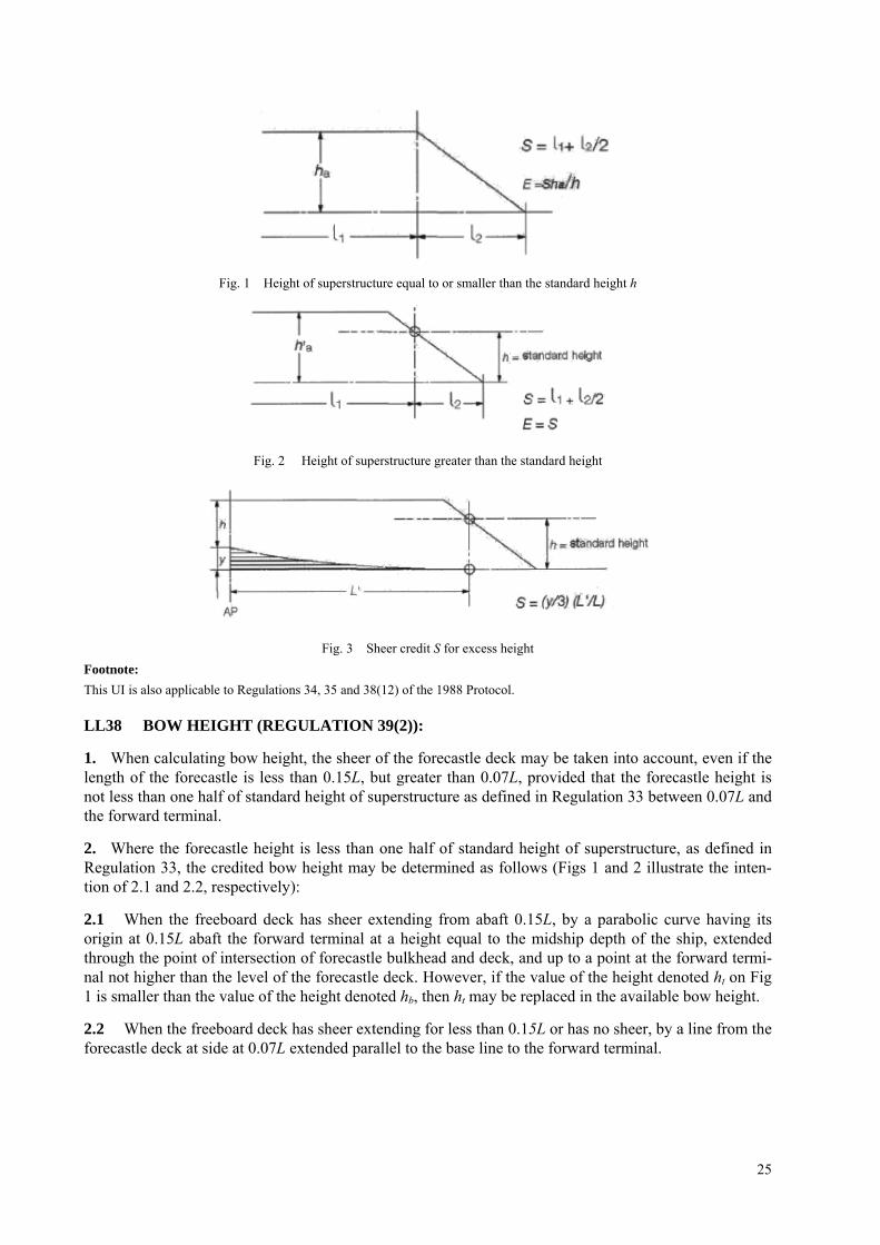
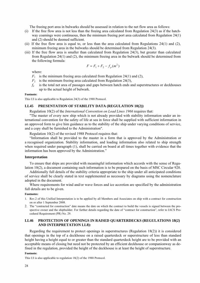
LL37 SUPERSTRUCTURES WITH SLOPING END BULKHEADS (REGULATIONS 34, 35 AND 38(12)):
When taking account of superstructures which have sloping end bulkheads in the calculations of free-boards, such superstructures shall be dealt with in the following manner:
(a) Regulation 34:
(i) When the height of superstructure, clear of slope, is equal to or smaller than the standard height, length S is to be obtained as shown in Fig 1.
(ii) When the height is greater than the standard, length S is to be obtained as shown in Fig 2. (iii) The foregoing will apply only when the slope, related to the base line, is 15° or greater. Where the
slope is less than 15°, the configuration will be treated as sheer.
(b) Regulation 35:
When the height of the superstructure, clear of the slope, is less than the standard height, its effective length E shall be its length S as obtained from (a)(i), reduced in the ratio of the actual height to the stan-dard height.
(c) Regulation 38(12):
When a poop or a forecastle has sloping end bulkheads, the sheer credit may be allowed on account of excess height, the formula given in Regulation 38(12) shall be used, the values for y and L' being as shown in Fig 3.
25
Fig. 1 Height of superstructure equal to or smaller than the standard height h
Fig. 2 Height of superstructure greater than the standard height
Fig. 3 Sheer credit S for excess height Footnote: This UI is also applicable to Regulations 34, 35 and 38(12) of the 1988 Protocol.
LL38 BOW HEIGHT (REGULATION 39(2)):
1. When calculating bow height, the sheer of the forecastle deck may be taken into account, even if the length of the forecastle is less than 0.15L, but greater than 0.07L, provided that the forecastle height is not less than one half of standard height of superstructure as defined in Regulation 33 between 0.07L and the forward terminal.
2. Where the forecastle height is less than one half of standard height of superstructure, as defined in Regulation 33, the credited bow height may be determined as follows (Figs 1 and 2 illustrate the inten-tion of 2.1 and 2.2, respectively):
2.1 When the freeboard deck has sheer extending from abaft 0.15L, by a parabolic curve having its origin at 0.15L abaft the forward terminal at a height equal to the midship depth of the ship, extended through the point of intersection of forecastle bulkhead and deck, and up to a point at the forward termi-nal not higher than the level of the forecastle deck. However, if the value of the height denoted ht on Fig 1 is smaller than the value of the height denoted hb, then ht may be replaced in the available bow height.
2.2 When the freeboard deck has sheer extending for less than 0.15L or has no sheer, by a line from the forecastle deck at side at 0.07L extended parallel to the base line to the forward terminal.

26
ht
ht
zt
Fig. 1
ht
Fig. 2
ht = Half standard height of superstructure as defined in regulation 33.
tb
bt zx
LZh −⎟⎟⎠
⎞⎜⎜⎝
⎛=
215.0
Footnote: This UI is also applicable to Regulation 39(2) of the 1988 Protocol.
LL39 STRUCTURE OF A LOWER FREEBOARD DECK (REGULATION 3(9)):
When a lower deck is designated as the freeboard deck, it shall be continuous in fore and aft direction as well as athwartship. Such freeboard deck as a minimum shall consist of suitably framed stringers at the ship sides and transversely at each watertight bulkhead which extends to the upper deck, within cargo spaces. The width of these stringers shall not be less than can be conveniently fitted having regard to the structure and the operation of the ship. Any arrangement of stringers shall be such that structural re-quirement can also be met. Footnote: This UI is also applicable to Regulation 3(9) of the 1988 Protocol.
Note Member Societies formulated this Interpretation in order to have a guide when judging whether a structure below the uppermost complete deck can be designated as freeboard deck in terms of Regulation 3(9) for the application of tonnage regulation. This was done, although it is obvious that such a structure has no significance with regard to the philosophy of the Load Line Convention.
Nevertheless it is felt that it would be preferable if tonnage and load line matters could be clearly separated by deleting from the Load Line Convention the reference to a lower deck being designated as the freeboard deck.

27
LL40 SECURITY OF HATCH COVERS (REGULATION 15(13)):
Acceptable equivalent means to steel bars shall consist of devices and materials which will provide strength equivalent to, and elasticity not greater than that of, steel.
Steel wire ropes cannot be regarded as satisfactory equivalent means. Care is to be taken that tarpaulins are adequately protected from the possibility of damage arising
from the use of securing devices which do not provide a flat bearing surface. Footnotes:
1. This UI is also applicable to Regulation 15(13) of the 1988 Protocol. 2. This UI is also applicable to Regulation 15(12) of the revised 1988 Protocol.
LL41 TRUNKS (REGULATIONS 29, 36 AND 38):
(a) Where the length of a trunk, corrected for breadth and height as may be appropriate, can be in-cluded in the effective length used for calculating the correction for superstructures in accordance with Regulation 37, it shall not be taken into account for calculating the total length S for the pur-pose of sheer correction according to Regulation 38(13).
(b) The effective length of superstructures E which is used for calculating the freeboard correction ac-cording to Regulation 29 shall be determined excluding the length of trunks.
(c) The inclusion of a trunk in the calculation of freeboard need not prohibit the fitting of openings in the bulkheads of adjacent superstructures such as poops, bridges or forecastles provided there is no direct communication between the superstructure and the trunk.
(d) The sides of a trunk included in the calculation of freeboard shall be intact. Side scuttles of the non-opening type and bolted manhole covers may be allowed.
Footnote:
This UI is also applicable to Regulations 29, 36 and 38 of the 1988 Protocol.
LL42 ACCESS OPENINGS ON BARGES (REGULATION 27(11)):
(a) Since Regulation 27(11) does not contain any indication as to what size the term 'small access openings' refers, it is recommended that such openings should not be greater than 1.5 m2 where a freeboard reduction of 25% is granted.
(b) Access plates are considered as being equivalent to an intact deck for unmanned barges, thereby allowing for a 25% reduction in freeboard, provided they are secured by closely spaced bolts, their joining parts are properly gasketed and their arrangements, for all practical purposes, have equiva-lent structural integrity and tightness as an intact deck.
Footnote:
This UI is also applicable to Regulation 27(14)(c) of the 1988 Protocol and the revised 1988 Protocol.
LL43 MINIMUM BOW HEIGHT (REGULATION 39):
On ships to which timber freeboards are assigned Regulation 39 should relate to the summer load wa-terline and not to the timber summer load waterline. Footnote:
This UI is also applicable to Regulation 39 of the 1988 Protocol.
LL44 FREEING PORTS (REGULATION 24(3)):
The effectiveness of the freeing area in bulwarks required by Regulation 24(1) and (2) depends on free flow across the deck of a ship. Where there is no free flow due to the presence of a continuous trunk or hatchway coaming, the freeing area in bulwarks is calculated in accordance with Regulation 24(3).
The free flow area on deck is the net area of gaps between hatchways, and between hatchways and superstructures and deckhouses up to the actual height of the bulwark.
28
The freeing port area in bulwarks should be assessed in relation to the net flow area as follows: (i) If the free flow area is not less than the freeing area calculated from Regulation 24(3) as if the hatch-
way coamings were continuous, then the minimum freeing port area calculated from Regulation 24(1) and (2) should be deemed sufficient.
(ii) If the free flow area is equal to, or less than the area calculated from Regulations 24(1) and (2), minimum freeing area in the bulwarks should be determined from Regulation 24(3).
(iii) If the free flow area is smaller than calculated from Regulation 24(3), but greater than calculated from Regulation 24(1) and (2), the minimum freeing area in the bulwark should be determined from the following formula:
)( 221 mfFFF p−+=
where: F1 is the minimum freeing area calculated from Regulation 24(1) and (2), F2 is the minimum freeing area calculated from Regulation 24(3), fp is the total net area of passages and gaps between hatch ends and superstructures or deckhouses
up to the actual height of bulwark. Footnote: This UI is also applicable to Regulation 24(3) of the 1988 Protocol.
LL45 PRESENTATION OF STABILITY DATA (REGULATION 10(2)) Regulation 10(2) of the International Convention on Load Lines 1966 requires that: "The master of every new ship which is not already provided with stability information under an in-
ternational convention for the safety of life at sea in force shall be supplied with sufficient information in an approved form to give him guidance as to the stability of the ship under varying conditions of service, and a copy shall be furnished to the Administration".
Regulation 10(2) of the revised 1988 Protocol requires that: “Information shall be provided to the master in a form that is approved by the Administration or
a recognised organization. Stability information, and loading information also related to ship strength when required under paragraph (1), shall be carried on board at all times together with evidence that the information has been approved by the Administration.”
Interpretation
To ensure that ships are provided with meaningful information which accords with the sense of Regu-lation 10(2), a document containing such information is to be prepared on the basis of MSC Circular 920.
Additionally full details of the stability criteria appropriate to the ship under all anticipated conditions of service shall be clearly stated in text supplemented as necessary by diagrams using the nomenclature adopted in the document.
Where requirements for wind and/or wave forces and ice accretion are specified by the administration full details are to be given. Footnotes: 1. Rev.2 of this Unified Interpretation is to be applied by all Members and Associates on ship with a contract for construction
on or after 1 September 2008. 2. The “contracted for construction” date means the date on which the contract to build the vessels is signed between the pro-
spective owner and the shipbuilder. For further details regarding the date of “contract for construction”, refer to IACS Pro-cedural Requirement (PR) No. 29.
LL46 PROTECTION OF OPENINGS IN RAISED QUARTERDECKS (REGULATIONS 18(2) AND INTERPRETATION LL8):
Regarding the requirement to protect openings in superstructures (Regulation 18(2)) it is considered that openings in the top of a deckhouse on a raised quarterdeck or superstructure of less than standard height having a height equal to or greater than the standard quarterdeck height are to be provided with an acceptable means of closing but need not be protected by an efficient deckhouse or companionway as de-fined in the regulation, provided the height of the deckhouse is at least the height of superstructure. Footnote: This UI is also applicable to regulation 18(2) of the 1988 Protocol.

29
LL47 GUARD RAILS:
A. GUARD RAILS (Regulation 25(2) and (3) of 1966 ICLL and the 1988 Protocol):
Regulation 25(2) and (3) of 1966 ICLL read: (2) Efficient guard rails or bulwarks shall be fitted to all exposed parts of the freeboard and superstruc-
ture decks. The height of the bulwarks or guard rails shall be at least 1 m (39 inches) from the deck, provided that where this height would interfere with the normal operation of the ship, a lesser height may be approved if the Administration is satisfied that adequate protection is provided.
(3) The opening below the lowest course of the guard rails shall not exceed 230 mm (9 inches). The other courses shall be not more than 380 mm (15 inches) apart. In the case of ships with rounded gunwales the guard rail supports shall be placed on the flat of the deck.
INTERPRETATION
(a) Fixed, removable or hinged stanchions shall be fitted about 1,5 m apart. (b) At least every third stanchion shall be supported by a bracket or stay. In lieu of this, flat steel stan-
chions shall be of increased breadth as given in Figure 1, and aligned with member below deck unless the deck plating thickness exceeds 20 mm.
(c) Wire ropes may only be accepted in lieu of guard rails in special circumstances and then only in limited lengths.
(d) Lengths of chain may only be accepted in lieu of guard rails if they are fitted between two fixed stanchions and/or bulwarks.
(e) The openings between courses should be in accordance with Regulation 25(3) of the Convention. (f) Wires shall be made taut by means of turnbuckles. (g) Removable or hinged stanchions shall be capable of being locked in the upright position.
Fig.1
Guardrail stanchion of increased breadth, welded to deck with double continuous fillet weld with leg size of min. 7 mm or as specified by the design standard.

30
B: GUARD RAILS (Regulation 25(3)(b) of the 1988 Protocol to the ICLL 1966 as amended by Resolution MSC.143(77):
Regulation 25(3)(b) of the 1988 Protocol to the ICLL 1966 as amended by resolution MSC.143(77) reads: (b) At least every third stanchion shall be supported by a bracket or stay.
INTERPRETATION
As alternate arrangements (required by Regulation 25(3)(b)), flat steel stanchions shall be of in-creased breadth as given in Figure 1, and aligned with member below deck unless the deck plating thick-ness exceeds 20 mm. Note: 1. Rev.2 was withdrawn in Nov 2006, to remove ambiguity in referencing relevant regulations. 2. Rev.2.1 of this UI is to be uniformly applied by IACS Societies to ships contracted for construction on or after 1 April 2007.
However, Societies are not precluded from applying this UI before such date. 3. The “contracted for construction” date means the date on which the contract to build the vessel is signed between the pro-
spective owner and shipbuilder. For further details regarding the date of “contract for construction”, refer to IACS Proce-dural Requirement (PR) No. 29.
LL48 MOULDED DEPTH (REGULATIONS 3(5)(c) AND 3(9) AND REGULATION 40(1)):
Discontinuous Freeboard Deck, Stepped Freeboard Deck.
1 Where a step exists in the freeboard deck, creating a discontinuity extending over the full breadth of the ship, and this step is in excess of one meter in length, Reg. 3(9) shall apply. (Fig 1). A step one meter or less in length shall be treated as a recess in accordance with paragraph 2.
2 Where a recess is arranged in the freeboard deck, and this recess does not extend to the side of the ship, the freeboard calculated without regard to the recess is to be corrected for the consequent loss of buoyancy. The correction would be equal to the value obtained by dividing the volume of the recess by the waterplane area of the ship at 85% of the least moulded depth. (Fig 2). The correction would be a straight addition to the freeboard obtained after all other corrections have been applied, except bow height correction. Where the freeboard, corrected for lost buoyancy as above, is greater than the minimum geometric freeboard determined on the basis of a moulded depth measured to the bottom of the recess, the latter value may be used.
3 Recesses in a second deck, designated as the freeboard deck, may be disregarded in this Interpreta-tion provided all openings in the weather deck are fitted with weathertight closing appliances.
4 Due regard is to be given to the drainage of exposed recesses and to free surface effects on stability.
5 This Interpretation is not intended to apply to dredgers, hopper barges or other similar types of ships with large open holds, where each case would require individual consideration.

31
Fig. 2
Correction is addition to freeboard equal to:
DWPAreadbl r
85.0@⋅⋅
Footnotes: 1. This UI is also applicable to Regulations 3(5)(c), 3(9) and 40(1) of 1988 Protocol. 2. Paragraph 1 should be replaced with the following sentence: “A step one metre or less in length shall be treated as a recess in
accordance with Reg. 32-1.” When this UI applies to revised 1988 Protocol paragraphs from 2 to 5 are not applicable to the revised 1988 Protocol.
LL49 AIR PIPE CLOSING DEVICES (REGULATION 20):
Where required by Regulation 20 air pipe closing devices shall be weathertight. Closing devices shall be automatic if, while the vessel is at its draught corresponding to summer load line, the openings of air pipes to which these closures are fitted submerge at angles up to 40° or up to a lesser angle which may be agreed on the basis of stability requirements. Pressure-vacuum valves (PV valves) may, however, be ac-cepted on tankers.
Wooden plugs and trailing canvas hoses shall not be accepted in position 1 and position 2. Footnotes: 1. This UI is also applicable to Regulation 20 of 1988 Protocol. 2. The first and last sentences of this UI are also applicable to Reg.20(3) of the revised 1988 Protocol. Note The Member Societies in formulating this interpretation realise that pressure-vacuum valves (PV valves) presently installed on tankers do not theoretically provide complete watertightness. In view, however, of experience of this type of valve and the posi-tion in which they are normally fitted it was considered they could be accepted
LL50 PROTECTION OF CREW (REGULATIONS 25(4), 26(2), 27(7) AND SOLAS II-1/3-3):
When applying Regulations 25(4), 26(2) and 27(7) of the ICLL 1966, as well as Regulation II-1/3-3 of SOLAS the protection of crew should be provided at least one of the means denoted in the table given below:

32
Acceptable arrangements according to type of freeboard assignee Type of
Ship Locations of access in Ship Assigned Summer
Freeboard Type A
Type B-100
Type B-60
Type B&B+
1 2 3 4 5 6 7
< 3000 mm
a b e
a b e
a b
c(l) e
f(l)
a b
c(l) c(2) c(4)
1.1 Access to midship quarters 1.1.1 Between poop and bridge, or 1.1.2 Between poop and deckhouse containing living accommodation or navigating equipment, or both.
> 3000 mm
a b e
a b e
a b
c(l) c(2)
e f(l) f(2)
d(l) d(2) d(3)
e f(l) f(2) f(4)
1.2 Access to Ends 1.2.1 Between poop and bow (if there is no bridge),
< 3000 mm
a b
c(l) e
f(l)
a b
c(l) c(2)
e f(l) f(2)
a b
c(l) c(2)
e f(l) f(2)
1.2.2 Between bridge and bow, or 1.2.3 Between a deckhouse containing living accommodation or navigating equipment, or both,
a b
c(l) d(l) e
f(1)
a b
c(l) c(2) d(l) d(2)
a b
c(l) c(2) c(4) d(l)
1.2.4 In the case of a flush deck vessel, be-tween crew accommodation and the forward and after ends of ship
All Ships other than
oil tankers*, chemical tankers*
and gas
carriers*
>3000 mm
e f(l) f(2)
d(2) d(3)
e f(l) f(2) f(4)
1 2 3 4
2.1 Access to Bow 2.1.1. Between poop and bow or 2.1.2. Between a deckhouse containing living accommodation or navigating equipment, or both, and bow, or
≤ (Af +Hs)**
a e
f(l) f(5)
2.1.3. In the case of a flush deck vessel, between crew accommoda-tion and the forward ends of ship.
> (Af + Hs)**
a e
f(l) f(2)
oil tankers*, chemical
tankers* and gas carriers*
2.2 Access to after end in the case of a flush deck vessel, between crew accommodation and the after end of ship.
as required in 1.2.4 for other types of ships
* Oil Tankers, Chemical Tanker and Gas Carrier as defined in SOLAS II-1/2.12, VII/8.2 and VII/11.2 respectively ** Af : the minimum summer freeboard calculated as type A ship regardless of the type freeboard actually assigned.
Hs : the standard height of superstructure as defined in ICLL Regulation 33.
For oil tanker, as defined in SOLAS II-1/2.12, chemical tankers as defined in SOLAS VII/8.2 or gas carriers as defined in SOLAS VII/11.2, constructed before 1st July 1998, existing arrangements which complied with (b) or (c) may be accepted in lieu of (e) or (f) provided such existing arrangements are fit-ted with shelters and means of access to and from the deck as required for the arrangements (e) or (f) as defined below.

33
For tankers less than 100 m in length, the minimum width of the gangway platform or deck level walkway fitted in accordance with arrangement (e) or (f), respectively, may be reduced to 0.6 m.
Acceptable arrangements referred to in the table are defined as follows: (a) A well lighted and ventilated under-deck passageway (clear opening 0.8 m wide, 2.0 m high) as close
as practicable to the freeboard deck, connecting and providing access to the locations in question. (b) A permanent and efficiently constructed gangway fitted at or above the level of the superstructure
deck on or as near as practicable to the center line of the ship, providing a continuous platform at least 0.6 m in width and a non-slip surface, with guard rails extending on each side throughout its length. Guard rails shall be at least 1 m high with courses as required in Load Line Regulation 25(3), and supported by stanchions spaced not more than 1.5 m; a foot-stop shall be provided.
(c) A permanent walkway at least 0.6 m in width fitted at freeboard deck level consisting of two rows of guard rails with stanchions spaced not more than 3 m. The number of courses of rails and their spac-ing are to be as required by Regulation 25(3). On Type B ships, hatchway coamings not less than 0.6 m in height may be regarded as forming one side of the walkway, provided that between the hatchways two rows of guard rails are fitted.
(d) A 10 mm minimum diameter wire rope lifeline supported by stanchions about 10 m apart, or a sin-gle hand rail or wire rope attached to hatch coamings, continued and adequately supported between hatchways.
(e) A permanent and efficiently constructed gangway fitted at or above the level of the superstructure deck on or as near as practicable to the center line of the ship: – located so as not to hinder easy access across the working areas of the deck; – providing a continuous platform at least 1.0 m in width; – constructed of fire resistant and non-slip material; – fitted with guard rails extending on each side throughout its length; guard rails should be at least
1.0 m high with courses as required by Regulation 25(3) and supported by stanchions spaced not more than 1.5 m;
– provided with a foot stop on each side; – having openings, with ladders where appropriate, to and from the deck. Openings should not be
more than 40 m apart; – having shelters of substantial construction set in way of the gangway at intervals not exceeding
45 m if the length of the exposed deck to be traversed exceeds 70 m. Every such shelter should be capable of accommodating at least one person and be so constructed as to afford weather pro-tection on the forward, port and starboard sides.
(f) A permanent and efficiently constructed walkway fitted at freeboard deck level on or as near as practica-ble to the center line of the ship having the same specifications as those for a permanent gangway listed in (e) except for foot-stops. On Type B ships (certified for the carriage of liquids in bulk), with a combined height of hatch coaming and fitted hatch cover of together not less than 1 m in height the hatchway coamings may be regarded as forming one side of the walkway, provided that between the hatchways two rows of guard rails are fitted.
Alternative transverse locations for (c),(d) and (f) above, where appropriate: (1) At or near center line of ship; or fitted on hatchways at or near center line of ship. (2) Fitted on each side of the ship. (3) Fitted on one side of the ship, provision being made for fitting on either side. (4) Fitted on one side only. (5) Fitted on each side of the hatchways as near to the center line as practicable. Footnotes: 1. This UI will be applied by all Members and Associates for ships that are subject to the referenced ICLL and SOLAS Regula-
tions. 2. This UI is also applicable to Regulations 25(4), 26(2) and 27(8) of 1988 Protocol. Notes: 1. In all cases where wire ropes are fitted, adequate devices are to be provided to ensure their tautness. 2. Wire ropes may only be accepted in lieu of guard rails in special circumstances and then only in limited lengths. 3. Lengths of chain may only be accepted in lieu of guard rails if fitted between two fixed stanchions. 4. Where stanchions are fitted, every 3rd stanchion is to be supported by a bracket or stay.
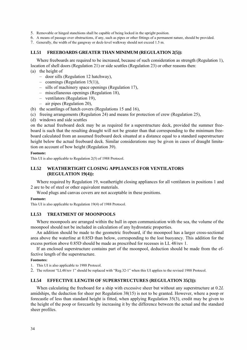
34
5. Removable or hinged stanchions shall be capable of being locked in the upright position. 6. A means of passage over obstructions, if any, such as pipes or other fittings of a permanent nature, should be provided. 7. Generally, the width of the gangway or deck-level walkway should not exceed 1.5 m.
LL51 FREEBOARDS GREATER THAN MINIMUM (REGULATION 2(5)):
Where freeboards are required to be increased, because of such consideration as strength (Regulation 1), location of shell doors (Regulation 21) or side scuttles (Regulation 23) or other reasons then: (a) the height of
– door sills (Regulation 12 hatchway), – coamings (Regulation 15(1)), – sills of machinery space openings (Regulation 17), – miscellaneous openings (Regulation 18), – ventilators (Regulation 19), – air pipes (Regulation 20),
(b) the scantlings of hatch covers (Regulations 15 and 16), (c) freeing arrangements (Regulation 24) and means for protection of crew (Regulation 25), (d) windows and side scuttles on the actual freeboard deck may be as required for a superstructure deck, provided the summer free-board is such that the resulting draught will not be greater than that corresponding to the minimum free-board calculated from an assumed freeboard deck situated at a distance equal to a standard superstructure height below the actual freeboard deck. Similar considerations may be given in cases of draught limita-tion on account of bow height (Regulation 39). Footnote: This UI is also applicable to Regulation 2(5) of 1988 Protocol.
LL52 WEATHERTIGHT CLOSING APPLIANCES FOR VENTILATORS (REGULATION 19(4)):
Where required by Regulation 19, weathertight closing appliances for all ventilators in positions 1 and 2 are to be of steel or other equivalent materials.
Wood plugs and canvas covers are not acceptable in these positions. Footnote: This UI is also applicable to Regulation 19(4) of 1988 Protocol.
LL53 TREATMENT OF MOONPOOLS Where moonpools are arranged within the hull in open communication with the sea, the volume of the
moonpool should not be included in calculation of any hydrostatic properties. An addition should be made to the geometric freeboard, if the moonpool has a larger cross-sectional
area above the waterline at 0.85D than below, corresponding to the lost buoyancy. This addition for the excess portion above 0.85D should be made as prescribed for recesses in LL 48/rev 1.
If an enclosed superstructure contains part of the moonpool, deduction should be made from the ef-fective length of the superstructure. Footnotes: 1. This UI is also applicable to 1988 Protocol. 2. The referent “LL48/rev 1” should be replaced with “Reg.32-1” when this UI applies to the revised 1988 Protocol.
LL54 EFFECTIVE LENGTH OF SUPERSTRUCTURES (REGULATION 35(3)): When calculating the freeboard for a ship with excessive sheer but without any superstructure at 0.2L
amidships, the deduction for sheer per Regulation 38(15) is not to be granted. However, where a poop or forecastle of less than standard height is fitted, when applying Regulation 35(3), credit may be given to the height of the poop or forecastle by increasing it by the difference between the actual and the standard sheer profiles.

35
When the height of the superstructure, clear of the slope, is less than the standard height, its effective length E shall be its length S as obtained from (a)(i), reduced in the ratio of the actual height to the (b). Footnote: This UI is also applicable to Regulation 35(3) of 1988 Protocol.
LL55 LEAST MOULDED DEPTH FOR A SHIP WITH A RAKE OF KEEL (REGULATION 3(1)):
For a ship with a rake of keel, least moulded depth, Dmld is found by drawing a line parallel to the keel line of the vessel (including skeg) tangent to the moulded sheer line of the freeboard deck, as illustrated in the above sketch. The least moulded depth is the vertical distance measured from the top of the keel to the top of the freeboard deck beam at side at the point of tangency.
Depth for freeboard, D, may then be found. Footnote: This UI is also applicable to Regulation 3(1) of 1988 Protocol.
LL56 BLOCK COEFFICIENT OF A PONTOON (REGULATION 3(7)) When calculating the block coefficient of a pontoon, according to the definition of Regulation 3(7),
the 96%-length, if applicable, shall be used disregarding the fact that this might lead to a coefficient greater than 1.0. Footnote: This UI is also applicable to Regulation 3(7) of 1988 Protocol.
LL57 BLOCK COEFFICIENT OF A MULTI-HULL CRAFT (REGULATION 3(7)): When calculating the block coefficient (Cb) of a multi-hull craft according to the definition of Regula-
tion 3(7), the full breadth (B) as defined in regulation 3(4) is to be used and not the breadth of a single hull. Footnote: This UI is also applicable to Regulation 3(7) of 1988 Protocol.
LL58 MACHINERY SPACE AND EMERGENCY GENERATOR ROOM VENTILATOR COAMING HEIGHTS (REGULATIONS 17(2), 19(3) AND 19(4)):
Regulation 17(2) requires that the coamings of machinery space ventilators situated in exposed positions on the freeboard and superstructure decks be as high above the deck as is reasonable and practicable.
In general, ventilators necessary to continuously supply the machinery space and, on demand, imme-diately supply the emergency generator room should have coamings which comply with regulation 19(3), without having to fit weathertight closing appliances.
However, where due to vessel size and arrangement this is not practicable, lesser heights for machin-ery space and emergency generator room ventilator coamings may be accepted with provision of weathertight closing appliances in accordance with regulation 19(4) in combination with other suitable arrangements to ensure an uninterrupted, adequate supply of ventilation to these spaces. Footnote: This UI is also applicable to Regulations 17(2), 19(3) and 19 (4) of 1988 Protocol.
LL59 CARGO MANIFOLD GUTTER BARS – FREEING ARRANGEMENTS AND INTACT STABILITY (ICLL REGULATION 24(1)(g) AND REGULATION 26):
ICLL 1988, as amended by res. MSC.143(77), Regulation 24 Freeing Ports:
(1)(g) Gutter bars greater than 300 mm in height fitted around the weather decks of tankers in way of cargo manifolds and cargo piping shall be treated as bulwarks. Freeing ports shall be arranged in accordance with this regulation. Closures attached to the freeing ports for use during loading and discharge operations are to be arranged in such a way that jamming cannot occur while at sea.
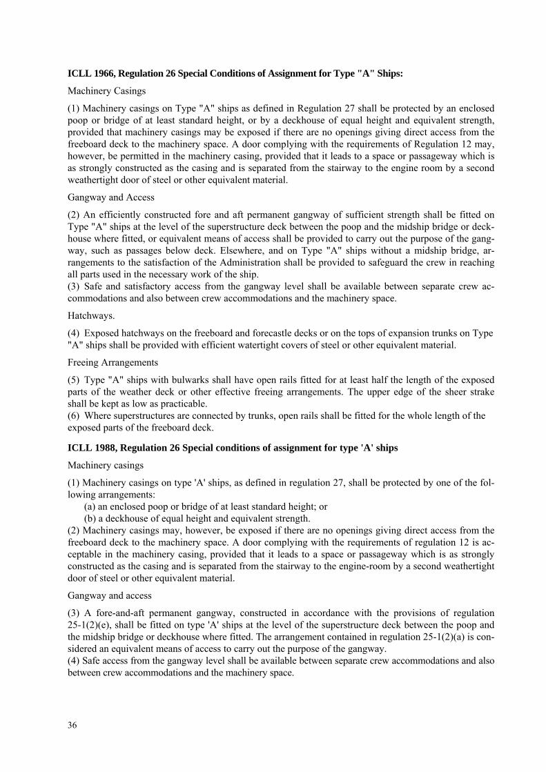
36
ICLL 1966, Regulation 26 Special Conditions of Assignment for Type "A" Ships:
Machinery Casings
(1) Machinery casings on Type "A" ships as defined in Regulation 27 shall be protected by an enclosed poop or bridge of at least standard height, or by a deckhouse of equal height and equivalent strength, provided that machinery casings may be exposed if there are no openings giving direct access from the freeboard deck to the machinery space. A door complying with the requirements of Regulation 12 may, however, be permitted in the machinery casing, provided that it leads to a space or passageway which is as strongly constructed as the casing and is separated from the stairway to the engine room by a second weathertight door of steel or other equivalent material.
Gangway and Access
(2) An efficiently constructed fore and aft permanent gangway of sufficient strength shall be fitted on Type "A" ships at the level of the superstructure deck between the poop and the midship bridge or deck-house where fitted, or equivalent means of access shall be provided to carry out the purpose of the gang-way, such as passages below deck. Elsewhere, and on Type "A" ships without a midship bridge, ar-rangements to the satisfaction of the Administration shall be provided to safeguard the crew in reaching all parts used in the necessary work of the ship. (3) Safe and satisfactory access from the gangway level shall be available between separate crew ac-commodations and also between crew accommodations and the machinery space.
Hatchways.
(4) Exposed hatchways on the freeboard and forecastle decks or on the tops of expansion trunks on Type "A" ships shall be provided with efficient watertight covers of steel or other equivalent material.
Freeing Arrangements
(5) Type "A" ships with bulwarks shall have open rails fitted for at least half the length of the exposed parts of the weather deck or other effective freeing arrangements. The upper edge of the sheer strake shall be kept as low as practicable. (6) Where superstructures are connected by trunks, open rails shall be fitted for the whole length of the exposed parts of the freeboard deck.
ICLL 1988, Regulation 26 Special conditions of assignment for type 'A' ships
Machinery casings
(1) Machinery casings on type 'A' ships, as defined in regulation 27, shall be protected by one of the fol-lowing arrangements:
(a) an enclosed poop or bridge of at least standard height; or (b) a deckhouse of equal height and equivalent strength.
(2) Machinery casings may, however, be exposed if there are no openings giving direct access from the freeboard deck to the machinery space. A door complying with the requirements of regulation 12 is ac-ceptable in the machinery casing, provided that it leads to a space or passageway which is as strongly constructed as the casing and is separated from the stairway to the engine-room by a second weathertight door of steel or other equivalent material.
Gangway and access
(3) A fore-and-aft permanent gangway, constructed in accordance with the provisions of regulation 25-1(2)(e), shall be fitted on type 'A' ships at the level of the superstructure deck between the poop and the midship bridge or deckhouse where fitted. The arrangement contained in regulation 25-1(2)(a) is con-sidered an equivalent means of access to carry out the purpose of the gangway. (4) Safe access from the gangway level shall be available between separate crew accommodations and also between crew accommodations and the machinery space.

37
Hatchways
(5) Exposed hatchways on the freeboard and forecastle decks or on the tops of expansion trunks on type 'A' ships shall be provided with efficient watertight covers of steel or other equivalent material.
Freeing arrangements
(6) Type 'A' ships with bulwarks shall have open rails fitted for at least half the length of the weather deck or other equivalent freeing arrangements. A freeing port area, in the lower part of the bulwarks, of 33% of the total area of the bulwarks, is an acceptable equivalent freeing arrangement. The upper edge of the sheer strake shall be kept as low as practicable. (7) Where superstructures are connected by trunks, open rails shall be fitted for the whole length of the exposed parts of the freeboard deck.
Interpretation
Where gutter bars are installed on the weather decks of tankers in way of cargo manifolds and are ex-tended aft as far as the after house front for the purpose of containing cargo spills on deck during loading and discharge operations, the free surface effects caused by containment of a cargo spill during liquid transfer operations or of boarding seas while underway require consideration with respect to the vessel’s available margin of positive initial stability (GMo).
Where the gutter bars installed are greater than 300 mm in height, they are to be treated as bulwarks according to the Load Line Convention with freeing ports arranged in accordance with Regulation 24 and effective closures provided for use during loading and discharge operations. Attached closures are to be arranged in such a way that jamming cannot occur while at sea, ensuring that the freeing ports will re-main fully effective.
On ships without deck camber, or where the height of the installed gutter bars exceeds the camber, and for tankers having cargo tanks exceeding 60% of the vessel’s maximum beam at midships regardless of gutter bar height, gutter bars should not be accepted without an assessment of the initial stability (GMo) for compliance with the relevant intact stability requirement taking into account the free surface effect caused by liquids contained by the gutter bars. Note: Rev.1 of this Unified Interpretation is to be uniformly implemented by all Members and Associates from 1 July 2008, unless otherwise instructed by a Flag State.
LL60 FREEING PORTS IN WAY OF WELLS IN COMBINATION WITH OPEN SUPERSTRUCTURES (REGULATIONS 24(1) AND 24(4)):
In the case of vessels having open superstructures on the freeboard or superstructure decks, which open to wells formed by bulwarks on the peripheries of the open decks, the convention leaves to the satisfaction of the Administration how the freeing port areas for the open spaces within the superstructures are to be calculated.
Since water can enter only through the end bulkhead openings, the freeing port areas for the open spaces within the superstructures should be a function of the breadth of the end openings and the extent to which wells formed by the open decks and common spaces within the open superstructures are cov-ered by the open superstructures.
To determine the minimum freeing port area on each side of the ship for the open superstructure (As) and for the open well (Aw), the following procedure is recommended:
1 Determine the total well length (lt) equal to the sum of the length of the open deck enclosed by bul-warks (lw) and the length of the common space within the open superstructure (lts).
2 To determine (As):
2.1 Calculate the freeing port area (A) required for an open well of length lt in accordance with regula-tion 24(1) with standard height bulwark assumed.

38
2.2 Multiply by the factor of 1.5 to correct for the absence of sheer, if applicable, in accordance with regulation 24(2).
2.3 Multiply by the factor (bo/lt) to adjust the freeing port area for the breadth (bo) of the openings in the end bulkhead of the enclosed superstructure. (Note: this cancels the lt terms from the (calculation)).
2.4 To adjust the freeing port area for that part of the entire length of the well which is enclosed by the open superstructure, multiply by the factor:
2)/(1 tw ll− , where: lw and lt are defined in 1 above.
2.5 To adjust the freeing port area for the distance of the well deck above the freeboard deck, multiply by the factor:
)/(5.0 ws hh , where: hw is the distance of the well deck above the freeboard deck and hs is one standard superstructure height.
3 To determine (Aw).
3.1 The freeing port area for the open well (Aw) is to be calculated in accordance with step 2.1 above, using lw to calculate (A'), and then adjusted for the actual height of the bulwark (hb) by the application of one of the following area corrections, whichever is applicable: For bulwarks greater than 1.2 m in height:
)004.0))(10.0/()2.1(( −= bwC hlA m2
For bulwarks less than 0.9 m in height: )004.0))(10.0/()9.0(( −= bwC hlA m2
For bulwarks between 1.2 m and 0.9 m in height: 00.0=CA m2
3.2 The corrected freeing port area, (Aw = A' + Ac), is then adjusted for absence of sheer, if applicable, and height above freeboard deck as in steps 2.2 and 2.5 above, using hs and hw.
4 The resulting freeing port areas for the open superstructure (As) and for the open well (Aw) are to be provided along each side of the open space covered by the open superstructure and each side of the open well respectively.
5 The above relationships are summarized by the following equations, assuming lt, the sum of lw and ls, is greater than 20 m*: Freeing port area Aw for the open well: Aw = (0.07 lw+ Ac) (sheer correction) (0.5hs/hw) Freeing port area As for the open superstructure: As = (0.07lt) (sheer correction) (bo/lt) (1-(lw/lt)2) (0.5hs/hw) * Where lt is 20 m or less, the basic freeing port area is A = 0.7 + 0.035lt in accordance with Regulation 24 (1). Units are to be consistent with those in the Convention. Footnote: This UI is also applicable to Regulation 24(1) and 24(4) of the 1988 Protocol.
LL61 METHOD OF CORRECTION FOR THE EFFECT OF FREE SURFACE OF LIQUIDS IN TANKS (REGULATION 10(2), UR L3 AND UI LL 45):
1 For all loading conditions, the initial metacentric height and the righting lever curve should be cor-rected for the effect of free surfaces of liquids in tanks.
2 Free surface effects will exist whenever the filling level in a tank is less than 100% and greater than 0%. Where the total free surface effects of nominally full (i.e. 98% or above) tanks is small in relation to the metacentric height of the vessel, with the agreement of the administration the effects for such tanks may be ignored. Free surface effects should be considered whenever the filling level in a tank is less than 98%.
39
3 Tanks which are taken into consideration when determining the free surface correction may be in one of two categories:
3.1 Tanks with filling levels fixed (e.g. liquid cargo, water ballast). The free surface correction should be determined for the actual filling level to be used in each tank.
3.2 Tanks with filling levels variable (e.g. consumable liquids such as fuel oil, diesel oil, and fresh wa-ter, and also liquid cargo and water ballast during liquid transfer operations). Except as permitted in 5 and 6, the free surface correction should be the maximum value attainable between the filling limits en-visaged for each tank, consistent with any operating instructions.
4 In calculating the free surface effects in tanks containing consumable liquids, it should be assumed that for each type of liquid at least one transverse pair or a single centerline tank has a free surface and the tank or combination of tanks taken into account should be those where the effect of free surfaces is the greatest.
5 Where water ballast tanks, including anti-rolling tanks and anti-heeling tanks, are to be filled or dis-charged during the course of a voyage, the free surface effects should be calculated to take account of the most onerous transitory stage relating to such operations.
6 For vessels engaged in liquid transfer operations, the free surface corrections at any stage of the liq-uid transfer operations may be determined in accordance with the filling level in each tank at that stage of the transfer operation.
7 The corrections to the initial metacentric height and to the righting lever curve should be addressed separately as follows:
7.1 In determining the correction to initial metacentric height, the transverse moments of inertia of the tanks should be calculated at 0 degrees angle of heel according to the categories indicated in 3.
7.2 The righting lever curve may be corrected by any of the following methods subject to the agree-ment of the Administration:
.1 Correction based on the actual moment of fluid transfer for each angle of heel calculated.
.2 Correction based on the moment of inertia, calculated at 0 degrees angle of heel, modified at each angle of heel calculated, (i.e.: GG1sinθ).
.3 Correction based on the summation of Mfs values for all tanks taken into consideration, see 8. With the exception of item 7.2.3 above, corrections may be calculated according to the categories in-
dicated in 3. Whichever method is selected for correcting the righting lever curve, only that method should be pre-
sented in the vessel's stability booklet. However, where an alternative method is described for use in manually calculating loading conditions, an explanation of the differences which may be found in the re-sults, as well as an example correction for each alternative, should be included.
8 The values of Mfs for each tank may be derived from the formula: δρkvbM fs =
where: Mfs is the free surface moment at any inclination in meter-tones, v is the tank total capacity in cubic meters, b is the tank maximum breadth in meters, ρ is the mass density of liquid in the tank in tones/cubic meters, δ is equal to v/blh (the tank block coefficient), h is the tank maximum height in meters, l is the tank maximum length in meters, k is the dimensionless coefficient to be determined from the following table according to the ratio b/h.
The intermediate values are determined by interpolation.

40
Table of Values for Coefficient “k” for Calculating Free Surface Corrections
hbk )
2tan1(
12sin 2 θθ
+=
where hb
≥θcot
)2
cot1()(12
cos)tan1(8
cos 2
2θθθθ
+−+=hbhb
k
where hb
≤θcot
θ b/h
5˚ 10˚ 15˚ 20˚ 30˚ 40˚ 45˚ 50˚ 60˚ 70˚ 75˚ 80˚ 85˚ θ
b/h 20 0.11 0.12 0.12 0.12 0.11 0.10 0.09 0.09 0.07 0.05 0.04 0.03 0.02 20 10 0.07 0.11 0.12 0.12 0.11 0.10 0.10 0.09 0.07 0.05 0.04 0.03 0.02 10 5 0.04 0.07 0.10 0.11 0.11 0.11 0.10 0.10 0.08 0.07 0.06 0.05 0.04 5 3 0.02 0.04 0.07 0.09 0.11 0.11 0.11 0.10 0.09 0.08 0.07 0.06 0.05 3 2 0.01 0.03 0.04 0.06 0.09 0.11 0.11 0.11 0.10 0.09 0.09 0.08 0.07 2
1.5 0.01 0.02 0.03 0.05 0.07 0.10 0.11 0.11 0.11 0.11 0.10 0.10 0.09 1.5 1 0.01 0.01 0.02 0.03 0.05 0.07 0.09 0.10 0.12 0.13 0.13 0.13 0.13 1
0.75 0.01 0.01 0.02 0.02 0.04 0.05 0.07 0.08 0.12 0.15 0.15 0.16 0.16 0.75 0.5 0.00 0.01 0.01 0.02 0.02 0.04 0.04 0.05 0.09 0.16 0.18 0.21 0.23 0.5 0.3 0.00 0.00 0.01 0.01 0.01 0.02 0.03 0.03 0.05 0.11 0.19 0.27 0.34 0.3 0.2 0.00 0.00 0.00 0.01 0.01 0.01 0.02 0.02 0.04 0.07 0.13 0.27 0.45 0.2 0.1 0.00 0.00 0.00 0.00 0.00 0.01 0.01 0.01 0.02 0.04 0.06 0.14 0.53 0.1
9 Small tanks which satisfy the following condition using the values of "k" corresponding to an angle of inclination of 30 degrees, need not be included in the correction:
01.0/ min <Δδρkvb m
where Δmin = the minimum ship displacement in tones.
10 The usual remainder of liquids in empty tanks need not be taken into account in calculating the corrections providing the total of such residual liquids does not constitute a significant free surface effect. Footnote: This UI is also applicable to Regulation 10(2) of the 1988 Protocol and the revised 188 Protocol.
LL62 SIDE SCUTTLES, WINDOWS AND SKYLIGHTS (REGULATION 23):
(1) Side scuttles and windows together with their glasses, deadlights1 and storm covers, if fitted, shall be of approved design and substantial construction in accordance with, or equivalent to, recognized national or international standards. Non-metallic frames are not acceptable.
(2) Side scuttles are defined as being round, or oval, openings with an area not exceeding 0.16 square meters. Round or oval openings having areas exceeding 0.16 square meters shall be treated as win-dows.
(3) Windows are defined as being rectangular openings generally, having a radius at each corner rela-tive to the window size in accordance with recognized national or international standards, and round, or oval, openings with an area exceeding 0.16 square meters.
(4) Side scuttles to the following spaces shall be fitted with efficient hinged inside deadlights: a) spaces below freeboard deck b) spaces within the first tier of enclosed superstructures c) first tier deckhouses on the freeboard deck protecting openings leading below or considered
buoyant in stability calculations.
1 „Deadlights”, in accordance with recognized standards, are fitted to the inside of windows and side scuttles while “storm
covers”, of comparable specifications to deadlights, are fitted to the outside of windows, where accessible, and may be hinged or portable.

41
The deadlights shall be capable of being effectively closed and secured watertight if fitted below free-board deck and weathertight if fitted above. (5) Side scuttles shall not be fitted in such a position that their sills are below a line drawn parallel to the
freeboard deck at side and having its lowest point 2.5 percent of the breadth B, or 500 mm, whichever is the greatest distance, above the summer load line (or timber summer load line if assigned).
(6) Side scuttles shall be of the non-opening type in ships subject to damage stability regulations, if cal-culations indicate that they would become immersed by any intermediate stage of flooding or the fi-nal equilibrium waterplane in any required damage case.
(7) Windows shall not be fitted below the freeboard deck, in the first tier end bulkheads or sides of en-closed superstructures and in first tier deckhouses2 considered buoyant in the stability calculations or protecting openings leading below.
(8) Side scuttles and windows at the side shell in the second tier, protecting direct access below or con-sidered buoyant in the stability calculations, shall be provided with efficient hinged inside dead-lights capable of being effectively closed and secured weathertight.
(9) Side scuttles and windows set inboard from the side shell in the second tier, protecting direct access be-low to spaces listed in paragraph (4), shall be provided with either efficient hinged inside deadlights or, where they are accessible, permanently attached external storm covers of approved design and of sub-stantial construction and capable of being effectively closed and secured weathertight.
(10) Cabin bulkheads and doors in the second tier separating side scuttles and windows from a direct ac-cess leading below may be accepted in place of deadlights or storm covers fitted to the side scuttles and windows.
(11) Deckhouses situated on a raised quarter deck or on the deck of a superstructure of less than standard height may be regarded as being in the second tier as far as the provision of deadlights is concerned, provided the height of the raised quarter deck or superstructure is equal to, or greater than, the stan-dard quarter deck height.
(12) Fixed or opening skylights shall have glass thickness appropriate to their size and position as required for side scuttles and windows. Skylight glasses in any position shall be protected from mechanical dam-age and where fitted in positions 1 or 2, shall be provided with robust deadlights or storm covers perma-nently attached.
Footnotes: 1. This UI is also applicable to Regulation 23 of the 1988 Protocol. 2. Paragraph 7 of this UI is applicable to Reg. 23(7)(c) of the revised 1988 Protocol. 3. Paragraph 11 of this UI is applicable to Reg. 23(11) of the revised 1988 Protocol.
LL63 TREATMENT OF STEPS AND RECESSES IN TRANSVERSE SUBDIVISION BULKHEADS: IMO RES. A.320 (IX), PARAGRAPHS 12(d) AND 12(e), AND REGULATION 27(12)(d) AND (e), REVISED 1988 ICLL (MSC.143(77)):
Regulation 27, paragraphs 12(d) of 1988 ICLL as amended by Res. MSC.143(77) reads:
“Except where otherwise required by paragraph (10)(a), the flooding shall be confirmed to a single compartment between adjacent transverse bulkheads, provided that the inner longitudinal boundary of the compartment is not in a position within the transverse extent of assumed damage. Transverse bound-ary bulkheads of wing tanks, which do not extend over the full breadth of the ship shall be assumed not to be damaged, provided that they extend beyond the transverse extent of assumed damage prescribed in subparagraph (b). If in a transverse bulkhead there are steps or recesses of not more than 3 m in length, located within the transverse extend of assumed damage as defined subparagraph (b), such transverse bulkhead may be considered intact and the adjacent compartment may be floodable singly. If, however, within the transverse extent of assumed damage there is a step or recess of more than 3 m in length in a transverse bulkhead, the two compartments adjacent to this bulkhead shall be considered as flooded. The step formed by the afterpeak bulkhead and the afterpeak tank shall not be regarded as a step for the purpose of this regulation.”
2 Two members reserved their position for those cases where the first tier is not considered buoyant, provided efficient dead-
lights are fitted.
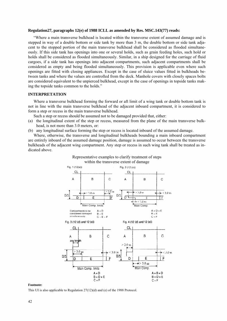
42
Regulation27, paragraphs 12(e) of 1988 ICLL as amended by Res. MSC.143(77) reads:
“Where a main transverse bulkhead is located within the transverse extent of assumed damage and is stepped in way of a double bottom or side tank by more than 3 m, the double bottom or side tank adja-cent to the stopped portion of the main transverse bulkhead shall be considered as flooded simultane-ously. If this side tank has openings into one or several holds, such as grain feeding holes, such hold or holds shall be considered as flooded simultaneously. Similar, in a ship designed for the carriage of fluid cargoes, if a side tank has openings into adjacent compartments, such adjacent compartments shall be considered as empty and being flooded simultaneously. This provision is applicable even where such openings are fitted with closing appliances. Except in the case of sluice values fitted in bulkheads be-tween tanks and where the values are controlled from the deck. Manhole covers with closely spaces bolts are considered equivalent to the unpierced bulkhead, except in the case of openings in topside tanks mak-ing the topside tanks common to the holds.”
INTERPRETATION
Where a transverse bulkhead forming the forward or aft limit of a wing tank or double bottom tank is not in line with the main transverse bulkhead of the adjacent inboard compartment, it is considered to form a step or recess in the main transverse bulkhead.
Such a step or recess should be assumed not to be damaged provided that, either: (a) the longitudinal extent of the step or recess, measured from the plane of the main transverse bulk-
head, is not more than 3.0 meters, or: (b) any longitudinal surface forming the step or recess is located inboard of the assumed damage.
Where, otherwise, the transverse and longitudinal bulkheads bounding a main inboard compartment are entirely inboard of the assumed damage position, damage is assumed to occur between the transverse bulkheads of the adjacent wing compartment. Any step or recess in such wing tank shall be treated as in-dicated above.
Representative examples to clarify treatment of steps within the transverse extent of damage
Footnote: This UI is also applicable to Regulation 27(12)(d) and (e) of the 1988 Protocol.
43
Note: 1. This UI shall be uniformly implemented by all IACS Members and Associates to ships contracted for construction after
1 January 1999. 2. The "contracted for construction" date means the date on which the contract to build the vessel is signed between the pro-
spective owner and the shipbuilder. For further details regarding the date of "contract for construction", refer to IACS Proce-dural Requirement (PR) No. 29.
3. Longitudinal distance of 3.0 (m) referred in sub-item (a) and figures 1 to 4 should be replaced with 3.05 (m), when this in-terpretation applies to Res. A.320.
LL64 NON-WEATHERTIGHT HATCH COVERS ABOVE SUPERSTRUCTURE DECK (LOAD LINE CONVENTION 1966 REGULATIONS 2 (5) AND 14(2)):
The requirements for coaming height and weathertightness of hatch covers located above the super-structure deck are left to the satisfaction of the flag Administration by Regulations 2 (5) and 14(2) of the Load Line Convention. Exposed coamings and hatch covers situated above the second tier of the super-structure, or equivalent, or above the third tier, or equivalent, in the forward quarter of the ship's length, may be regarded to be above the superstructure deck in the application of 14(2). Non-weathertight covers in these locations may be accepted subject to the approval of the flag Administration and conditional upon the following: 1. Their acceptance should be limited to use on container ships. 2. They may be fitted to hatchways located on weather decks which are at least two standard superstruc-
ture heights above an actual freeboard deck or an assumed freeboard deck from which a freeboard can be calculated which will result in a draught not less than that corresponding to the freeboard actually assigned. Where any part of a hatchway is forward of a point located one quarter of the ship's length (0.25L) from the forward perpendicular, that hatchway is to be located on a weatherdeck at least three standard superstructure heights above the actual or assumed freeboard deck. It is to be noted that the as-sumed freeboard deck is used only for the purpose of measuring the height of the deck on which the hatchways are situated and may be an imaginary, or virtual deck and in this case is not to be used for the actual assignment of freeboard. The vessels freeboard is to be assigned from an actual deck, desig-nated as the freeboard deck, which is to be determined in accordance with the Convention and LL39.
3. The hatchway coamings should be not less than 600 mm in height. 4. The non-weathertight gaps between hatch cover panels should be considered as unprotected openings
with respect to the requirements of intact and damage stability calculations. They should be as small as possible commensurate with the capacity of the bilge system and expected water ingress, and the capacity and operational effectiveness of the fire-fighting system and, generally, should not exceed 50 mm.
5. Labyrinths, gutter bars, or equivalents should be fitted proximate to the edges of each panel in way of the gaps to minimize the amount of water that can enter the container hold from the top surface of each panel.
6. Scantlings of the hatch cover panels are to be equivalent to those for weathertight covers and in ac-cordance with the applicable requirements of UR S21 and UI LL70. The details on the securing ar-rangements to the vessel's support structure and coamings are provided in IACS Recommendation No. 14.
7. Bilge alarms should be provided in each hold fitted with non-weathertight covers, Footnote: This UI is also applicable to Regulations 2(5) and 14(2) of the 1988 Protocol and the revised 1988 Protocol.
Note: 1. This Unified Interpretation is to be uniformly implemented by all Members and Associates from 1 July 1999, unless other-
wise instructed by a Flag State. 2. Changes introduced in Rev.3 are to be uniformly implemented by IACS Members and Associates from 1 January 2002. 3. Changes introduced in Rev.4 are to be uniformly implemented by IACS Members and Associate from 1 January 2006.

44
LL65 SHIPS WITH ASSIGNED OR REASSIGNED REDUCED FREEBOARDS AND INTENDED TO CARRY DECK CARGO
SOLAS, CHAPTER II-1, REGULATION 4, FOOTNOTES .6 AND .7:
"Cargo ships shown to comply with the following regulations may be excluded from the application of part B-1: .6 Damage stability requirements of regulation 27 of the 1966 Load Lines Convention as applied in
compliance with resolutions A.320(IX) and A.514(13), provided that in the case of cargo ships to which regulation 27(9) applies, main transverse watertight bulkheads, to be considered effective, are spaced according to paragraph (12)(f) of resolution A.320(IX), except ships intended for the carriage of deck cargo; and
.7 Damage stability requirements of regulation 27 of the 1988 Load Lines Protocol, except ships in-tended for the carriage of deck cargo".
General:
1. This UI pertains to ships intended to carry deck cargo and assigned or reassigned reduced freeboards in accordance with Regulation 27 of the International Convention on Load Lines, 1966 (ICLL 1966) or the ICLL 1966 as amended by the 1988 Protocol.
2. In .6 and .7 of the footnotes to SOLAS Chapter II-1, Regulation 4, ships shown to comply with ICLL 1966 Regulation 27 as applied in compliance with IMO Res. A.320 and A.514, may be excluded from the application of SOLAS Chapter II-1 Part B-1, except if they carry deck cargo.
3. Therefore ships identified in item 1), above, shall: a) according to the assigned reduced freeboards, comply with damage stability requirements of
Regulation 27 of ICLL 1966 and the 1988 Protocol to the ICLL 1966; and b) according to the intended deck cargo capacity, be provided with the limiting GM or KG curve
required by SOLAS Chapter II-1, Regulation 5-1.4 in compliance with the probabilistic damage stability analysis of SOLAS Chapter II-1 Part B-1.
4. The KG used for demonstrating compliance with the criteria in 3 a) shall be the same as that used for the criteria in 3 b) at the deepest subdivision load line.
Footnote: This UI is also applicable to the revised 1988 Protocol. Note: 1. This UI LL 65 is to be uniformly implemented by IACS Members and Associates from 1 July 2001. 2. Revision 1 is to be uniformly implemented by IACS Members and Associates from 1 January 2009.
LL66 HATCH COVER STRESS/DEFLECTION CALCULATION (RES. MSC.143(77), 2005 LL PROTOCOL REGULATION 16(5)(a) & (b)):
Regulation 16 Hatchways closed by weathertight covers of steel or other equivalent materials
Hatch cover minimum design loads
(5) All hatch covers shall be designed such that: (a) the product of the maximum stress determined in accordance with the above loads and the factor of
1.25 does not exceed the minimum upper yield point strength of the material in tension and the criti-cal buckling strength in compression;
(b) the deflection is limited to not more than 0.0056 times the span,
INTERPRETATION
In the calculation of stress and deflection from the prescribed mass per unit area, the design pressure is to be determined by using a vertical acceleration equal to 1.0g. Note: This UI LL 66 is to be uniformly implemented by IACS Members and Associates from 1 January 2005.
45
LL67 ENDORSEMENT OF CERTIFICATES WITH THE DATE OF COMPLETION OF THE SURVEY ON WHICH THEY ARE BASED:
"Resolutions MSC. 170(79), MSC.171(79), MSC. 172(79), MSC. 174(79) through MSC.179(79) and MSC.181(79) through MSC. 187(79) require that the identified certificates include the statement:
"Completion date of the survey on which this certificate is based: dd/mm/yyyy".
INTERPRETATION
For application of the above resolutions, the following IACS Unified Interpretation applies: The "Completion date of the survey on which this certificate is based", is the date of the last ini-
tial/renewal survey visit on which all statutory and class items, required to be surveyed, have been sur-veyed (regardless if they were found satisfactory or with minor deficiency). Note: 1. This UI is to be uniformly implemented by IACS Members and Associates from 1 March 2004. 2. Revision 1 of this UI is to be uniformly implemented by IACS Members and Associates from 1 July 2006.
LL68 POSITION OF FREEBOARD DECK ON FLOAT ON/FLOAT OFF BARGE CARRIERS (REGULATION 3(9)):
"Freeboard Deck. The freeboard deck is normally the uppermost complete deck exposed to weather and sea, which has permanent means of closing all openings in the weather part thereof, and below which all openings in the sides of the ship are fitted with permanent means of watertight closing. In a ship hav-ing a discontinuous freeboard deck, the lowest line of the exposed deck and the continuation of that line parallel to the upper part of the deck is taken as the freeboard deck. At the option of the owner and sub-ject to the approval of the Administration, a lower deck may be designated as the freeboard deck pro-vided it is a complete and permanent deck continuous in fore and aft direction at least between the ma-chinery space and peak bulkheads and continuous athwartships. When this lower deck is stepped the lowest line of the deck and the continuation of that line parallel to the upper part of the deck is taken as the freeboard deck. When a lower deck is designated as the freeboard deck, that part of the hull which extends above the freeboard deck is treated as a superstructure so far as concerns the application of the conditions of assignment and the calculation of freeboard. It is from this deck that the freeboard is calcu-lated"
Interpretation:
1. Float On/Float Off Barge Carriers are designed to be ballasted such that the bottom of their cargo space(s) (well deck) submerges below the waterline to allow barges being floated in and out.
2. If such a ship is fitted with weathertight closures for the cargo space(s) and a watertight enclosure at the stern, the uppermost complete deck may be taken as the freeboard deck.
3. If such a ship is not fitted with weathertight closures for the cargo space(s) or a watertight enclosure at the stern, the well deck shall be taken as the freeboard deck, while buoyant spaces above may be considered as superstructures in accordance with UI LL 15 or 88 Prot. Reg. 34(1).
4. If such a ship is not fitted with weathertight closures for the cargo space(s) but has a watertight enclo-sure at the stern, the uppermost complete deck may be taken as the freeboard deck provided that: – the structure of the freeboard deck complies with the requirements of LL39; – the calculated freeboard is corrected for any missing buoyancy above the well deck in accordance
with LL48, and – a satisfactory safety level at the resulting draught is demonstrated according to alternative con-
cepts. Footnote: This UI is also applicable to Regulation 3(9) of the 1988 Protocol and the revised 1988 Protocol.
Note: This UI is to be uniformly implemented by IACS Members and Associates from 1 April 2005.

46
LL69 INTERPRETATION TO 1966 ICLL REG. 27
REGULATION 27 of ICLL 1966: IMO RES. A.320 PARAGRAPH 12:
"DAMAGE ASSUMPTIONS”
(12) The following principles regarding the character of the assumed damage apply: (a) The vertical extent of damage in all cases is assumed to be from the base line upwards without limit. (b) The transverse extent of damage is equal to B/5 or 11.5 meters (37.7 feet), whichever is the lesser,
measured inboard from the side of the ship perpendicularly to the centre line at the level of the sum-mer load water line.
(c) If damage of a lesser extent than specified in sub paragraphs (a) and (b) of this paragraph results in a more severe condition, such lesser extent shall be assumed.
(d) Except where otherwise required by paragraph (10)(a) the flooding shall be confined to a single compartment between adjacent transverse bulkheads provided the inner longitudinal boundary of the compartment is not in a position within the transverse extent of assumed damage. Transverse bound-ary bulkheads of wing tanks, which do not extend over the full breadth of the ship shall be assumed not to be damaged, provided they extend beyond the transverse extent of assumed damage prescribed in sub paragraph (b) of this paragraph.
If in a transverse bulkhead there are steps or recesses of not more than 3.05 meters (10 feet) in length located within the transverse extent of assumed damage as defined in sub-paragraph (b) of this paragraph, such transverse bulkhead may be considered intact and the adjacent compartment may be floodable singly. If, however, within the transverse extent of assumed damage there is a step or recess of more than 3.05 meters (10 feet) in length in a transverse bulkhead, the two compartments adjacent to this bulkhead shall be considered as flooded. The step formed by the after peak bulkhead and the af-ter peak tank top shall not be regarded as a step for the purpose of this Regulation.
(e) Where a main transverse bulkhead is located within the transverse extent of assumed damage and is stepped in way of a double bottom or side tank by more than 3.05 meters (10 feet), the double bot-tom or side tanks adjacent to the stepped portion of the main transverse bulkhead shall be considered as flooded simultaneously. If this side tank has openings into one or several holds, such as grain feeding holes, such hold or holds shall be considered as flooded simultaneously. Similarly in a ship designed for the carriage of fluid cargoes, if a side tank has openings into adjacent compartments, such adjacent compartments shall be considered as empty and flooded simultaneously. This provi-sion is applicable even where such openings are fitted with closing appliances, except in the case of sluice valves fitted in bulkheads between tanks and where the valves are controlled from the deck. Manhole covers with closely spaced belts are considered equivalent to the non-pierced bulkhead ex-cept in the case of openings in topside tanks making the topside tanks common to the holds.
f) Where the flooding of any two adjacent fore and aft compartments is envisaged main transverse wa-tertight bulkheads shall be spaced at least 1/3L2/3 or 14.5 meters (0.495L2/3 or 47.6 feet), whichever is the lesser, in order to be considered effective. Where transverse bulkheads are spaced at a lesser distance, one or more of these bulkheads shall be assumed as non-existent in order to achieve the minimum spacing between bulkheads."
Interpretation:
Treatment of the volume of the forecastle, which is located over the foremost cargo hold for damage stability calculation in accordance with Reg.27 of ICLL 1966: IMO Res. A.320 paragraph 12.
In the case where the forecastle overlaps foremost cargo hold, provided the forecastle bulkhead is not more than 3.05 m aft of the forward bulkhead of the hold and the deck forming the step in way is water-tight, then the bulkhead will be considered as continuous and not subject to damage. Footnote: The distance of 3.05 m referred in this UI should be replaced with 3.00 m, when this interpretation applies to the 1988 Protocol and revised 1988 Protocol. Note: This UI is to be uniformly implemented by IACS Members and Associates from 1 April 2005.

47
LL70 CORROSION MARGIN FOR HATCH COVER DESIGN (REG. 16 (5)(d), AMENDMENTS TO THE PROTOCOL OF 1988 RELATING TO THE INTERNATIONAL CONVENTION ON LOAD LINES, 1966 (RES. MSC. 143(77)):
Regulation 16 (5) (d) reads:
HATCHWAYS CLOSED BY WEATHERTIGHT COVERS OF STEEL OR OTHER EQUIVALENT MATERIAL
All hatch covers shall be designed such that: a) the product of the maximum stress determined in accordance with the above loads and the factor of
1.25 does not exceed the minimum upper yield point strength of the material in tension and the criti-cal buckling strength in compression;
b) the deflection is limited to not more that 0.0056 times the span; c) steel plating forming the tops of covers is not less in thickness that 1 % of the spacing of stiffeners or
6 mm if that be greater; and d) an appropriate corrosion margin is incorporated.
INTERPRETATION
The "appropriate corrosion margin" for hatch covers of cargo holds in position 1 and 2 and above, de-fined as the corrosion addition ts which is to be added to the net thickness tnet required by (a), (b) and (c) is: 1. for Bulk Carriers, Ore Carriers and Combination Carriers, as defined in UR Z11.2:
– single skin hatch covers, a corrosion addition ts = 2.0 mm for all plating and stiffeners; – double skin hatch covers, a corrosion addition ts = 2.0 mm for top and bottom plating and ts = 1.5 mm
for the internal structure. 2. for other vessels:
– single skin hatch covers, a corrosion addition ts = 2.0i) mm for all plating and stiffeners; – double skin hatch covers, a corrosion addition ts = 1.5i) mm for top and bottom plating and ts =
1.0 mm for the internal structure. i) Corrosion addition ts = 1.0 mm for the hatch covers in way of cellular cargo holds intended for containers.
The above corrosion margins have been defined based on the assumption that corrosion protection and renewals as given in UR S21.6.1 is complied with for all ship types subject to regulation 16 (5) (d) of the 1988 Load Line Protocol.
For corrosion addition ts = 1.0 mm it is assumed that the thickness for steel renewal is tnet and the thickness for coating or annual gauging is tnet + 0.5 mm. Note: This UI LL70 is to be uniformly implemented by IACS Members and Associates on ships constructed (i.e. keel laid) from 1st January 2005.
FREQUENTLY ASKED QUESTIONS"
(Note: This paper was prepared by IACS for external use. 16 August 2005).
Hatch Cover Design for General Cargo Ships and Container Ships
Question 1
Bulk Carriers
IACS S21 Rev.3 (April 2003) entered into force on 1 January 2004, and applies to ships contracted for construction on or after 1 January 2004.
When the bulk carrier hatch covers are designed according to IACS S21 Rev.3 (April 2003), do they also fulfill the MSC.143 (77) Annex 3 -Regulation 16 requirements?
ANSWER
It is confirmed that when bulk carrier hatch covers are designed according to IACS UR S21 Rev.3 (April 2003), they also fulfill the MSC.143 (77) Annex 3 -Regulation 16 requirements.
48
Question 2
Container Carriers and General Cargo Ships
In Resolution MSC.143 (77) Annex 3 (Adopted on 5 June 2003) -Regulation 16 (5)(d), it is stated that "an appropriate corrosion margin is incorporated'.
Can the same corrosion margin as for the conventional 1.75t/m2 weather load (as per the current Clas-sification Rules) be used for this purpose?
ANSWER
The current version of S21, applicable to bulk carriers, ore carriers and combination carriers, consid-ers only the sea pressures but a new version is presently under development for application to all types of ships and at this purpose also loads other than sea loads will be taken into account.
The unified requirements that will be developed by IACS for the design of hatch covers will be based on a net scantling approach.
The corrosion additions in UR S21 to be used also for other types of ships will be the same as the ones presently adopted for bulk carriers.
Until the new version of UR S21 is adopted by IACS, hatch covers for ships different from bulk carri-ers, ore carriers and combination carriers are to be designed in accordance with: – the requirements of ILLC, as far as sea loads are concerned ; – the current Classification Societies Rules.
Question 3
Container Carriers – special features
Interpretation of Resolution MSC.143 (77) Annex 3 (Adopted on 5 June 2003) – Regulation 16 – Ta-ble 16.2 for Container Carriers with L >100 m: Can the following interpretation be applied?
Longitudinal position
FP 0.25L Aft of 0.25L
L >100 m
Freeboard Deck Equation in 16 (2) (a) 3.5 t/m2 3.5 t/m2
1st superstructure deck 3.5 t/m2 3.5 t/m2 2.6 t/m2
2nd superstructure deck 2.6 t/m2 2.6 t/m2 2.1 t/m2
3rd superstructure deck 2.1 t/m2 2.1 t/m2 2.1 t/m2
ANSWER
The design loads can be reduced from 2.6 t/m2 to 2.1 t/m2, as proposed above, for locations other than positions 1 and 2, as defined in ILLC.
The following considerations have been given for accepting a load reduction: – Position 2 is defined in the Amendments to the Protocol of 1988 with respect to the exposed super-
structure decks. – The meaning of "located at least one (or two, when forward of 0.25L from forward perpendicular)
standard height of superstructure above the freeboard deck", relevant to the "position 2" definition, should be interpreted as: decks of superstructures having height less than one (two) standard height(s) of superstructure are to be considered as being in "position 1".
In conclusion, locations more than two (or three, when forward of 0.25L from forward perpendicular) standard height of superstructure above the freeboard deck are not position 2 and the design loads in these locations may be reduced with respect to those specified in ILLC.
Question 4
To determine the hatch cover location, can we use the "assumed freeboard deck" as defined in IACS UI LL64?
49
ANSWER
It is confirmed that LL 64 is to be used to determine the hatch cover location.
LL71 SIMILAR STAGE OF CONSTRUCTION (ART. 2 (6), REGULATIONS 2(7) AND (8)):
New ship means a ship the keel of which is laid, or which is at a similar stage of construction, on or after the date of coming into force of the present Convention for each Contracting Government.
Amended 1988 LL Protocol, regulation 2, paragraphs (7) and (8):
(7) Unless expressly provided otherwise, the regulations of this Annex shall apply to ships the keels of which are laid or which are at a similar stage of construction on or after 1 January 2005.
(8) For ships the keels of which are laid or which are at a similar stage of construction before 1 January 2005, the Administration shall ensure that the requirements which are applicable under the Interna-tional Convention on Load Lines, 1966, as modified by the Protocol of 1988 relating thereto, adopted by the International Conference on Harmonized System of Survey and Certification, 1988, are com-plied with.
Interpretation: The term "similar stage of construction" means the stage at which:
– construction identifiable with a specific ship begins; and – assembly of that ship has commenced comprising at least 50 tones or one per cent of the estimated
mass of all structural material, whichever is less. Footnote: This UI is also applicable to Article 2(6) of the 1988 Protocol and the revised 1988 Protocol. Note: This UI LL71 is to be uniformly implemented by IACS Members and Associate from 1 July 2005.
LL72 INTERPRETATION TO ICLL REGULATION 27
REGULATION
Regulation 27(3) reads: A type "A" ship, if over 150 m in length, and designed to have empty compartments when loaded to
her summer load water line, shall be able to withstand the flooding of any one of these empty compart-ments at an assumed permeability of 0.95, and remain afloat in a condition of equilibrium considered to be satisfactory by the Administration. In such a ship, if over 225 m in length, the machinery space shall be treated as a floodable compartment but with a permeability of 0.85.
INTERPRETATION
Members apply resolution A.320(IX) when certifying ships of non 1988 Protocol Parties under regu-lations 27(3) of the 1966 ICCL. Note: This UI is to be uniformly implemented by IACS Members and Associates to ships constructed on or after 1 January 2006.
LL74 MEASUREMENT OF DISTANCES
Several IMO instruments (e.g., ICLL, SOLAS and MARPOL Conventions, the IBC Code and the IGC Code, etc.) require distance to be measured such as tank length, height, width, ship (or subdivision or wa-terline) length, etc.
INTERPRETATION
Unless explicitly stipulated otherwise in the text of the regulations in SOLAS, Load Line and MARPOL Convention and any of their mandatory Codes, distances are to be measured by using moulded dimensions. Note: The Unified Interpretation is to be uniformly implemented by IACS Societies form 1 April 2009.

50
LL75 PERMEABILITY OF STORE SPACE IN THE DAMAGE STABILITY CALCULATION (REGULATION 27(3) & (8.D))
REGULATION
1. Reg. 27(3) of 1988 Protocol of 1966 ICLL and its amendment MSC.143(77) reads: “(3) A type "A" ship, if over 150 m in length, to which a freeboard less than type "B" has been as-signed, when loaded in accordance with the requirements of paragraph (11), shall be able to withstand the flooding of any compartment or compartments with an assumed permeability of 0.95, consequent upon the damage assumptions specified in paragraph (12), and shall remain afloat in a satisfactory condition of equilibrium, as specified in paragraph (13). In such a ship, the machinery space shall be treated as a floodable compartment, but with a permeability of 0.85.”
2. Reg. 27(8.d) of 1988 Protocol of 1966 ICLL and its amendment MSC.143(77) reads: “the ship, when loaded in accordance with the requirements of paragraph (11), shall be able to with-stand the flooding of any compartment or compartments, with an assumed permeability of 0.95, con-sequent upon the damage assumptions specified in paragraph (12), and shall remain afloat in a satis-factory condition of equilibrium, as specified in a satisfactory condition of equilibrium, as specified in paragraph (13). In such a ship, if over 150 m in length, the machinery space shall be treated as a floodable compartment, but with a permeability of 0.85”
INTERPRETATION
The permeability assumed in the damage stability calculation for the flooding of any store space shall be 0.95 under 1988 Protocol of 1966 ICLL. Note: 1. This Unified Interpretation is to be uniformly implemented by IACS Members and Associates for ships contract for con-
struction on or after 1 July 2009. 2. The “contracted for construction” date means the date on which the contract to build the vessel is signed between the pro-
spective owner and the shipbuilder. For further details regarding the date of “contract for construction”, refer to IACS Pro-cedural Requirement (PR) No/ 29.
LL76 INITIAL STATUTORY SURVEYS AT NEW CONSTRUCTION
1. Scope
The scope of this UI is to define the requirements for the initial statutory surveys at new construction as detailed in IMO Resolution A.997(25), which are not addresses in UR Z23 for the following as applicable: (i) International Load Line Certificate (1966); (ii) Cargo Ship Safety Equipment Certificate; (iii) International Oil Pollution Prevention Certificate.
This UI only covers the survey actives required and does not cover the technical interpretations of the statutory requirements or approval of plans, designs and manuals required by the Regulations.
2. This UI does not cover the requirements for type approval or certification at vendor’s works and for which evidence of acceptance is to be provided as indicated in the survey tables.
3. Definitions used in the survey tables
Survey Item A description of the survey item considered
Origin of the Requirement Applicable Statutory Regulation
Approved Drawings /Documentation
Indicates whether approved drawings/documentation is required
Conformity Verification This verification may consist of an examination of the certificate, a check of the marks or, for products which require type approval, to verify conformity of the product with the approved prototype or certification with Flag Administration requirements
Survey during construction or installation
Indicates whether the witness by surveyor of construction and installation on board is required
51
Tightness Testing Indicates whether tightness testing is required to be witnessed by the surveyor for survey item
Survey after construction or installation
Indicates whether the survey items is examined by the Surveyor after completion of its con-struction and installation an board
Function Test Indicates whether a survey item or system is to be subjected to a functioning and/or perform-ance test or trial in the presence of a Surveyor after installation on board
Onboard Verification of docu-mentation
Indicates whether the required documentation is to be verified on board by the surveyor
Series of Vessels As defined by IACS PR 29
4. Application
This UI applies to all vessels for which the statutory certificates listed in paragraph 1 are to be issued at new construction by IACS Societies.
5. Interpretation of the survey requirements are given in Appendix 1
Table 1 – Safety Equipment Table 2 – Load Line Table 3 – MARPOL Annex 1
6. Specific flag administration requirements, if any, supersede the requirements contained this UI.
7. Qualification and monitoring of personnel
The survey required by this UI shall be carried out by exclusive surveyors of the classification soci-ety, as defined in PR5. The surveyors are to be qualified to be able to carry out the tasks and procedures are to be in place the ensure that their activities are monitored.
Details are specified in PR 6 and PR 7.
8. Inspection and test plan for new building activities
The shipbuilder is to provide inspection and testing plan for the items which are required to be sur-veyed and/or tested prior to the commencement of the surveys and/or test.
9. Product and Type Approval Certificates
The shipbuilder is to provide product and type approval certificates for the applicable items listed in Appendix 1 to be placed on board.
10. Proof of the consistency of surveys
The classification society is to be able to provide evidence, e.g. through records, check list, inspection and the records, etc. that its surveyors have complied with the requirement of this UI. Note: This UI is to be uniformly implemented by IACS Societies on ships contracted for construction (as defined in IACS PR29) from 1st July 2010.
52
Appendix 1 to LL 76 Description
COLUMN 1 A.997(25) Requirements
COLUMN 2 Survey Item A description of the survey item considered
COLUMN 3 Origin of the Requirement Applicable Statutory Regulation
COLUMN 4 Correspondence with Approved Draw-ings/Documentation
Indicates whether approved drawings /documentation is required
COLUMN 5 Conformity Verification This verification may consist of an examination of the certifi-cate, a check of the marks or, for type approved products, to verify conformity of the product with the approved prototype or certification with National Requirements
COLUMN 6 Survey during construction or installa-tion
Indicates whether the witness by surveyor of fabrication and installation on board is required
COLUMN 7 Tightness Testing Indicates whether tightness testing is required to be witnessed by the surveyor for survey item
COLUMN 8 Survey after construction or installation Indicates whether the survey item is examined by the Sur-veyor after completion of its installation on board and/or construction
COLUMN 9 Function Test Indicates whether a system is to be subjected to a function-ing and/or performance test or trial in the presence of a Sur-veyor after installation on board
COLUMN 10 Onboard Verification of documentation Indicates whether the required documentation is to be veri-fied on board by the surveyor
53
Table 2 Load Line
A.997(25) Requirement Survey Item Origin of the Requirement
Cor
resp
onde
nce
with
ap
prov
ed d
raw
ings
/d
ocum
enta
tion
Con
form
ity v
erifi
catio
n
Surv
ey d
urin
g C
on-
stru
ctio
n or
Inst
alla
tion
Tigh
tnes
s Tes
t
Surv
ey a
fter C
onst
ruc-
tion
and
Inst
alla
tion
or I
nsta
llatio
n
Func
tion
Test
On
Boa
rd V
erifi
catio
n
of D
ocum
enta
tion
(LI) 1.1.2
For the load line the survey during construction and after installation should consist of:
(LI) 1.1.2.2
confirming that the deck line and load line mark are prop-erly positioned
Positioning of Deck Line and Load Line Mark
LLC 66/88 regs. 4 to 9
X X
(LI) 1.1.2.3
witnessing the inclining experiment or lightweight survey Inclining Experiment LLC 66/88/03 reg. 10
X X
Superstructure End Bulkheads (LI) 1.1.2.4
examining the superstructure end bulkheads and the open-ing therein Superstructure Openings
LLC 66/88 regs. 11 and 12 X X X X
Freeboarde Deck – Means of Secur-ing the weather tightness of Cargo Hatchways
X X X X
Freeboarde Deck – Means of Secur-ing the weather tightness of Other Hatchways
X X X
Freeboarde Deck – Means of Secur-ing the weather tightness of Other Openings
X X X
Superstructure Deck – Means of Se-curing the weather tightness of Cargo Hatchways
X X X X
Superstructure Deck – Means of Se-curing the weather tightness of Other Hatchways
X X X
(LI) 1.1.2.5
examining the means of securing the weather tightness of cargo hatchways, other hatchways and other openings on the freeboard and superstructure decks
Superstructure Deck – Means of Se-curing the weather tightness of Other Openings
LLC 66/88 regs. 13 to 18
X X X
54
A.997(25) Requirement Survey Item Origin of the Requirement
Cor
resp
onde
nce
with
ap
prov
ed d
raw
ings
/d
ocum
enta
tion
Con
form
ity v
erifi
catio
n
Surv
ey d
urin
g C
on-
stru
ctio
n or
Inst
alla
tion
Tigh
tnes
s Tes
t
Surv
ey a
fter C
onst
ruc-
tion
and
Inst
alla
tion
or I
nsta
llatio
n
Func
tion
Test
On
Boa
rd V
erifi
catio
n
of D
ocum
enta
tion
(LI) 1.1.2.6
examining the ventilators and air pipes, including their coamings and closing appliances
Ventilators and air pipe including their coamings and closing appliances
LLC 66/88 regs. 19 and 20
X X X
(LI) 1.1.2.7
examining the watertight integrity of the closures to any openings in the ship’s side below freeboard deck
Closures to any openings in the ship’s side below the freeboard deck
LLC 66/88 reg. 21
X X X X X
(LI) 1.1.2.8
examining the scuppers, inlets and discharges Scuppers, Inlets and Discharges LLC 66/88 reg. 22
X X X
(LI) 1.1.2.9
examining the garbage chutes Garbage chute LLC 66/88/03, reg. 22-1
X X X
Spurling Pipe X X X (LI) 1.1.2.10
examining the spurling pipes and cable lockers Cable Locker
LLC 66/88/03, reg. 22-2 X X X
(LI) 1.1.2.11
examining the side scuttles and deadlights Side Scuttles and Deadlights LLC 66/88 reg. 23
X X X X
Bulwarks X X Freeing Ports X X
(LI) 1.1.2.12
examining the bulwarks including the provision of freeing ports, special attention being given to any freeing ports fitted with shutters Freeing Ports fitted with shutters
LLC 66/88/03 reg. 24, 25
X X X Guardrails Gangways Walkways
(LI) 1.1.2.13
Examining the guardrails, gangways, walkways and other means provided for the protection of the crew and means for safe passage of crew
Other means
LLC 66/88/03 reg. 25, 25-1
X X
Machinery Casings Gangway and Access Hatchways
(LI) 1.1.2.14
Special requirements for ships permitted to sail with type “A” or type “B-minus” freeboards
Freeing arrangements
LLC 66/88/03 reg. 26, 27
X X X
Uprights X X Lashings X X Stability X X
(LI) 1.1.2.15
Checking, when applicable, of the fittings and appliances for timber deck cargoes
Protection of Crew
LLC 66/88 regs. 42 to 45
X X (LI) 1.1.3.1
Checking that the loading and ballasting information has been supplied to the master
Loading and Stability Manual LLc 66/88 reg. 10
X X

55
LL 77 APPLICATION OF LOAD LINE REQUIREMENTS TO CONVER- SIONS OF SINGLE-HULL OIL TANKERS TO DOUBLE-HULL OIL TANKERS OR BULK CARRIERS (ARTICLE(10))
Article 10 – ‘Repairs, alterations and modifications ‘ reads:
(1) A ship which undergoes repairs, alterations, modifications and outfitting related thereto shall continue to comply with at least the requirements previously applicable to the ship. An existing ship in such a case shall not, as a rule, comply to a lesser extent with the requirements for a new ship than it did before.
(2) Repairs, alterations and modifications of a major character and outfitting related thereto should meet the requirements for a new ship in so far as the administration deems reasonable and practicable.
Interpretation
1 For single-hull oil tankers converted to double-hull oil tankers:
1.2 The ship should meet the requirements of the regulations contained in Chapter III (Freeboards) of Annex I of the load line convention in effect at the date of conversion. In cases where there are no changes to the parameters which result in a change of the minimum freeboard3, and where there is no de-crease in magnitude of freeboard assigned after conversion, using the convention previously applicable to the ship in determining any change or decrease as mentioned above, the converted ship should continue to comply with at least the requirements previously applicable to the ship.
1.3 Any structure and/or equipment such as doors, hatches and cable lockers, etc., which is newly added, replaced or modified, is to comply with the requirements of the regulations contained in Chapter II (Conditions of assignment of freeboard) of Annex I of the convention in effect at the date of conver-sion.
2 For single-hull oil tankers converted to bulk carriers:
2.1 Any such conversion should be regarded as a modification of a major character and the ship should meet all the requirements of the regulations annexed to the Convention (including regulation 39) in effect at the date of conversion; and
2.2 Notwithstanding the above, the requirements of the regulations contained in Chapter II (Condi-tions of assignment of freeboard) of Annex I of the Convention in effect at the date of conversion, should be applied only to the structure and/or equipment, which is newly added, replaced, or modified.
3 The date on which a conversion occurs for the purpose of determining the applicability of require-ments for ships constructed on or after the date on which any relevant amendments enter into force should be:
3.1 The date on which the contract is placed for the conversion; or
3.2 In the absence of a contract, the date on which the work identifiable with the specific conversion begins; or
3.3 The completion date of the conversion4, if that occurs more than 3 years after the date specified in subparagraph 3.1 above or 30 months after the date specified in subparagraph 3.2 above, either as ap-plicable. Note: This Unified Interpretation is to apply to conversions which occur (as defined in paragraph 3) on or after 1 January 2013.
3 ‘which result in a change of the minimum freeboard’ should be understood as ‘which are used in determining the minimum
freeboard even though the minimum freeboard has no change in fact’ 4 where the completion date has been subject to delay beyond the period referred to in paragraph 3.3 above due to unforeseen
circumstances beyond the control of the builder and the owner, the other dates referred to in paragraph 3.1 or 3.2 above, if applicable, may be accepted by the Administration in lieu of the completion date of the conversion in accordance with MSC-MEPC.1/Circ.1247.
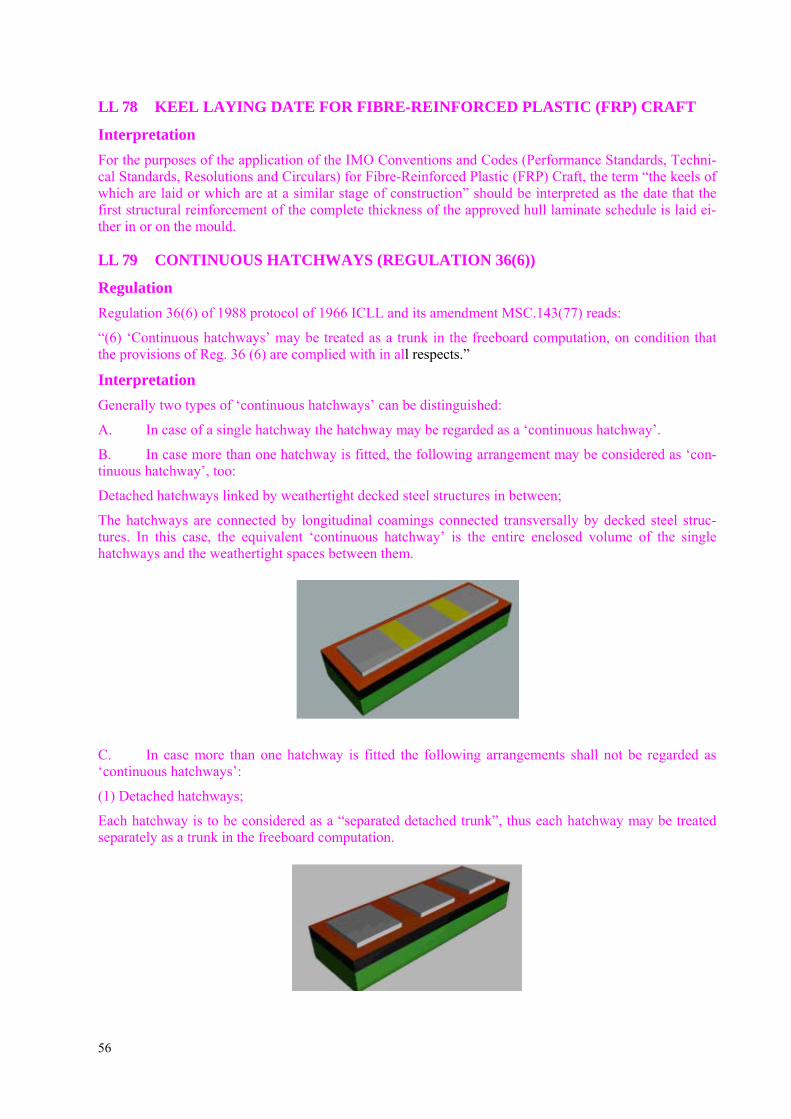
56
LL 78 KEEL LAYING DATE FOR FIBRE-REINFORCED PLASTIC (FRP) CRAFT
Interpretation For the purposes of the application of the IMO Conventions and Codes (Performance Standards, Techni-cal Standards, Resolutions and Circulars) for Fibre-Reinforced Plastic (FRP) Craft, the term “the keels of which are laid or which are at a similar stage of construction” should be interpreted as the date that the first structural reinforcement of the complete thickness of the approved hull laminate schedule is laid ei-ther in or on the mould.
LL 79 CONTINUOUS HATCHWAYS (REGULATION 36(6))
Regulation Regulation 36(6) of 1988 protocol of 1966 ICLL and its amendment MSC.143(77) reads:
“(6) ‘Continuous hatchways’ may be treated as a trunk in the freeboard computation, on condition that the provisions of Reg. 36 (6) are complied with in all respects.”
Interpretation Generally two types of ‘continuous hatchways’ can be distinguished:
A. In case of a single hatchway the hatchway may be regarded as a ‘continuous hatchway’.
B. In case more than one hatchway is fitted, the following arrangement may be considered as ‘con-tinuous hatchway’, too:
Detached hatchways linked by weathertight decked steel structures in between;
The hatchways are connected by longitudinal coamings connected transversally by decked steel struc-tures. In this case, the equivalent ‘continuous hatchway’ is the entire enclosed volume of the single hatchways and the weathertight spaces between them.
C. In case more than one hatchway is fitted the following arrangements shall not be regarded as ‘continuous hatchways’:
(1) Detached hatchways;
Each hatchway is to be considered as a “separated detached trunk”, thus each hatchway may be treated separately as a trunk in the freeboard computation.

57
(2) Detached hatchways connected by longitudinal coamings;
All hatchways may be treated in the same manner as (1).
List of changes effective as of 1 July 2015
Item Title/Subject Source
LL 78 Keel laying date for fibre-reinforced plastic (frp) craft IACS UI LL 78
LL 79 Continuous hatchways (regulation 36(6)) IACS UI LL 79 (New July 2014)

![IN THE WEATHERTIGHT HOMES TRIBUNAL · page | 1 in the weathertight homes tribunal tri-2011-100-000065 [2013] nzwht auckland 17 between carl santo saffioti and eija marita saffioti](https://img.dokumen.tips/doc/110x75/5c63ddbc09d3f2241d8be490/in-the-weathertight-homes-tribunal-page-1-in-the-weathertight-homes-tribunal.jpg)


![IN THE WEATHERTIGHT HOMES TRIBUNAL TRI-2008-100-000036 ...€¦ · in the weathertight homes tribunal tri-2008-100-000036 [2011] nzwht auckland 27 between vivienne diana lowe, graham](https://img.dokumen.tips/doc/110x75/60987b631995726e9d4c1b59/in-the-weathertight-homes-tribunal-tri-2008-100-000036-in-the-weathertight-homes.jpg)