Embed Size (px)
Citation preview
General rights Copyright and moral rights for the publications made accessible in the public portal are retained by the authors and/or other copyright owners and it is a condition of accessing publications that users recognise and abide by the legal requirements associated with these rights.
• Users may download and print one copy of any publication from the public portal for the purpose of private study or research. • You may not further distribute the material or use it for any profit-making activity or commercial gain • You may freely distribute the URL identifying the publication in the public portal
If you believe that this document breaches copyright please contact us providing details, and we will remove access to the work immediately and investigate your claim.
Downloaded from orbit.dtu.dk on: Jul 02, 2018
Interoperability between Modelling Tools (MoT) with Thermodynamic PropertyPrediction Packages (Simulis® Thermodynamics) and Process Simulators(ProSimPlus) Via CAPE-OPEN Standards
Morales Rodriguez, Ricardo; Gani, Rafiqul; Déchelotte, Stéphane; Vacher, Alain; Baudouin, Olivier
Published in:Thermodynamics
Publication date:2011
Document VersionPublisher's PDF, also known as Version of record
Link back to DTU Orbit
Citation (APA):Morales Rodriguez, R., Gani, R., Déchelotte, S., Vacher, A., & Baudouin, O. (2011). Interoperability betweenModelling Tools (MoT) with Thermodynamic Property Prediction Packages (Simulis® Thermodynamics) andProcess Simulators (ProSimPlus) Via CAPE-OPEN Standards. In M. Tadashi (Ed.), Thermodynamics (pp. 425-440). InTech.

20
Interoperability between Modelling Tools (MoT) with Thermodynamic Property Prediction
Packages (Simulis® Thermodynamics) and Process Simulators (ProSimPlus) Via CAPE-
OPEN Standards Ricardo Morales-Rodriguez1, Rafiqul Gani1, Stéphane Déchelotte2,
Alain Vacher2 and Olivier Baudouin2
1CAPEC, Technical University of Denmark 2ProSim S.A.
1Denmark 2France
1. Introduction Simulation and modelling continues to play a very important role for chemical engineers in the study, evaluation, development, etc., of chemical processes by producing different alternatives in the design/production of product/process of chemicals and thereby, avoiding expenses in experimentation. The CAPE-OPEN effort is a standardisation process for achieving true plug and play of process industry simulation software components and environments, where, CAPE-OPEN Laboratorties Network (CO-LaN) consortium is in charge of managing the lifecycle of the CAPE-OPEN standard (Belaud, 2002). The objective of CAPE-OPEN project was to clarify user priorities for process modelling software component/environment interoperability and promote the use of CAPE-OPEN standards to create commercially-valuable interoperability (Pons, 2005a). The follow-up of the CAPE-OPEN project, called the Global CAPE-OPEN project, focused on the development of standards in new subfields of process modelling and simulation addressing complex physical properties, kinetic models, new numerical algorithms and distributed models. Also, future support for the development of simulation software in the CAPE-OPEN-compliant interface components was established through the creation of the CO-LaN. The CO-LaN promotes the integration of open process simulation technology in the work process, and use of CAPE-OPEN compliant interoperated software for taking real industrial case studies and in assessing the use of CAPE-OPEN technology. In addition, CO-LaN provides support and user training; definition of open standards for new technologies beyond process modelling and simulation, developing prototypes for on-line systems, discrete and mixer batch-continuous processes, finer granularity interfaces, and scheduling and planning systems. Further dissemination of the technical results of CAPE-OPEN using

Thermodynamics
426
both traditional and internet-based mechanism; assessment of the use and benefits of CAPE-OPEN standards for educations and training (Braunschweig et al., 2000). Currently, several commercial simulator vendors, modelling tools developers, etc. have incorporated CAPE-OPEN standard in their products, allowing the user a better and easier manner for implementation/combination among process modelling components (PMC) and process modelling environments (PME) (Pons, 2003). CAPE-OPEN is an abstract specification that can be subsequently implemented in COM, CORBA and .NET for bridging PMCs and PMEs. Recently, .NET framework has been introduced as a new alternative to provide the interoperability among different platforms. This new technology has been presented by Microsoft and it seems to be visualized as the future of the connections between different platforms. CO-LaN has published guidelines on how to use .NET with CAPE-OPEN, this is available in CO-LaN website at http://www.colan.org/News/Y06/news-0616.htm. In this chapter, a connection between a modelling tool (ICAS-MoT) representing a PMC and external simulators (ProSimPlus and Simulis® Thermodynamics) representing a PME is established and implemented through the CAPE-OPEN standards and highlighted through two case studies. The interoperability issues of ICAS-MoT and Simulis® Thermodynamics are highlighted through case study number one. Here, a thermodynamic property model is generated by ICAS-MoT and wrapped to satisfy the CAPE-OPEN standard. A second case study highlights the interaction issues between ICAS-MoT and ProSimPlus regarding the use of a non-conventional unit operation (model generated in ICAS-MoT) plugged to the ProSimPlus simulator environment. Furthermore, as this unit operation model is employing a multiscale modelling approach, these issues are also highlighted through the case study.
2. What do we need for the Interoperability between modelling tool (MoT) and external simulators (ProSim)?
Fig. 1. Interoperability between the PMC and PME
Process modelling component (represented by ICAS-MoT) is able to achieve interoperability and be wrapped for use within a PME (represented by a simulation engine, external software and external simulator) through CAPE-OPEN interfaces. Fig. 1 illustrates the interaction that can be done between a PMC and a PME. This interaction has been applicated in this chapter for two case studies. In both cases, the ICAS-MoT is representing a

Interoperability between Modelling Tools (MoT) with Thermodynamic Property Prediction Packages (Simulis® Thermodynamics) and Process Simulators (ProSimPlus) Via CAPE-OPEN Standards
427
PMC with different models. In the first case, the PMC is integrated with a PME (represented by Simulis® Thermodynamics) while in the second case, the PMC is integrated with a PME (represented by one external simulator as ProSimPlus). To establish the integration, here, the following components are needed: • PME (Process Modelling Environment) • PMC (Process Modelling Component) • Middleware (COM) These are briefly explained below.
2.1 Process modelling component (PMC) Process modelling components are objects that can be added to the flowsheet to represent unit operations or mathematical/information/energy flows within the flowsheet, thermodynamic property models, reaction models or mathematical model solvers (Barrett, 2005). PMCs basically are pieces of software that are defined for a specific function. Most of the applications are for: physical properties, unit operation modules, numerical solver and flowsheet analysis tools. This work focuses mostly on the connection of PMCs related to physical properties and unit operation to an appropriate PME. As far as physical properties are concerned, they are an important part in the evaluation of chemical processes that involve some kind of phase equilibrium calculations (vapor-liquid, liquid-liquid, solid-liquid and so on) or some transport properties or the use of some derivatives of some properties with respect to temperature or pressure (i.e.; fugacity coefficients, enthalpy, etc.) using some equations of states or special correlations (depending on the property that it is being calculated) that cannot be easily found in some commercial or free software.
Fig. 2. CAPE-OPEN Unit operation In CAPE-OPEN compliant PMCs for unit operations, the interface includes ports that can be classified as material, energy and information ports. In this work, the notion of Material Object is used to represent a material stream. In fact, a CAPE-OPEN Material Object is a
Thermodynamics
428
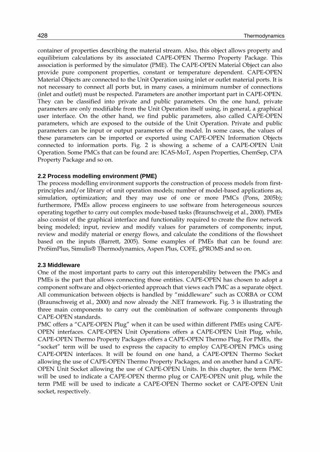
container of properties describing the material stream. Also, this object allows property and equilibrium calculations by its associated CAPE-OPEN Thermo Property Package. This association is performed by the simulator (PME). The CAPE-OPEN Material Object can also provide pure component properties, constant or temperature dependent. CAPE-OPEN Material Objects are connected to the Unit Operation using inlet or outlet material ports. It is not necessary to connect all ports but, in many cases, a minimum number of connections (inlet and outlet) must be respected. Parameters are another important part in CAPE-OPEN. They can be classified into private and public parameters. On the one hand, private parameters are only modifiable from the Unit Operation itself using, in general, a graphical user interface. On the other hand, we find public parameters, also called CAPE-OPEN parameters, which are exposed to the outside of the Unit Operation. Private and public parameters can be input or output parameters of the model. In some cases, the values of these parameters can be imported or exported using CAPE-OPEN Information Objects connected to information ports. Fig. 2 is showing a scheme of a CAPE-OPEN Unit Operation. Some PMCs that can be found are: ICAS-MoT, Aspen Properties, ChemSep, CPA Property Package and so on.
2.2 Process modelling environment (PME) The process modelling environment supports the construction of process models from first-principles and/or library of unit operation models; number of model-based applications as, simulation, optimization; and they may use of one or more PMCs (Pons, 2005b); furthermore, PMEs allow process engineers to use software from heterogeneous sources operating together to carry out complex mode-based tasks (Braunschweig et al., 2000). PMEs also consist of the graphical interface and functionality required to create the flow network being modeled; input, review and modify values for parameters of components; input, review and modify material or energy flows, and calculate the conditions of the flowsheet based on the inputs (Barrett, 2005). Some examples of PMEs that can be found are: ProSimPlus, Simulis® Thermodynamics, Aspen Plus, COFE, gPROMS and so on.
2.3 Middleware One of the most important parts to carry out this interoperability between the PMCs and PMEs is the part that allows connecting those entities. CAPE-OPEN has chosen to adopt a component software and object-oriented approach that views each PMC as a separate object. All communication between objects is handled by “middleware” such as CORBA or COM (Braunschweig et al., 2000) and now already the .NET framework. Fig. 3 is illustrating the three main components to carry out the combination of software components through CAPE-OPEN standards. PMC offers a “CAPE-OPEN Plug” when it can be used within different PMEs using CAPE-OPEN interfaces. CAPE-OPEN Unit Operations offers a CAPE-OPEN Unit Plug, while, CAPE-OPEN Thermo Property Packages offers a CAPE-OPEN Thermo Plug. For PMEs, the “socket” term will be used to express the capacity to employ CAPE-OPEN PMCs using CAPE-OPEN interfaces. It will be found on one hand, a CAPE-OPEN Thermo Socket allowing the use of CAPE-OPEN Thermo Property Packages, and on another hand a CAPE-OPEN Unit Socket allowing the use of CAPE-OPEN Units. In this chapter, the term PMC will be used to indicate a CAPE-OPEN thermo plug or CAPE-OPEN unit plug, while the term PME will be used to indicate a CAPE-OPEN Thermo socket or CAPE-OPEN Unit socket, respectively.

Interoperability between Modelling Tools (MoT) with Thermodynamic Property Prediction Packages (Simulis® Thermodynamics) and Process Simulators (ProSimPlus) Via CAPE-OPEN Standards
429
Fig. 3. CAPE-OPEN components
3. Case studies 3.1 Simulis® thermodynamic – ICAS-MoT The first case study is demonstrating the integration between ICAS-MoT and Simulis® Thermodynamics, which is carried out through the use of a DLL file as the middleware. Fig. 4 is illustrating the general structure of the combination of these different computational tools. The introduction of data is carried out through Simulis® Thermodynamics that provides a graphic interface for this purpose. Information (data) is transferred through the DLL file where variables that are shared between the integrated computational tools are specified. This information is transferred to ICAS-MoT to carry out the calculations using the ICAS-MoT solver. Afterwards, results are returned through the DLL file again
Fig. 4. ICAS-MoT interoperability with Simulis® Thermodynamics

Thermodynamics
430
and presented in the Simulis® Thermodynamics dialogs as the same way than calculations carried out using its native models. This case study is illustrated using the calculation of fugacity and activity coefficients where the mathematical (thermodynamic property) model is specified in the ICAS-MoT file.
Fugacity and Activity Coefficients Calculation In order to show the reliability of this integration, calculations of fugacity coefficients have been performed with three different mathematical models equations of state: SRK, SAFT and PC-SAFT. Note that the same middleware has been used for the different equations of state models (see Fig. 5). For instance, whether one wants to perform the calculations using the SAFT model and afterwards with the PC-SAFT model, the only “work” needed is to change the ICAS-MoT file and it would be possible to perform the calculations in Simulis® Thermodynamics without any extra effort. The data-flow taking place through the DLL file involves the following variables: temperature (T), pressure (P), vapour composition (Yv) and fugacity coefficients in vapour phase (Phiv). Among these variables, (T, P and Yv) are specified in Simulis® Thermodynamics and through the DLL file to ICAS-MoT, which then employs the specified model to calculate the fugacity coefficients (PhiV) sent it to Simulis® Thermodynamics through the DLL file.
Fig. 5. Structure for the calculation of fugacity and activity coefficients though the synergy between ICAS-MoT and Simulis® thermodynamic
As far as activity coefficient calculation is concerned, two different mathematical models have been performed: Wilson and UNIFAC models solution (see Fig. 5). The data-flow through DLL file involves: temperature (T), pressure (P), liquid composition (Xl) and activity coefficient (Gamma). T, P and Xl are also specified in Simulis® thermodynamics and sent them through the DLL file to ICAS-MoT, which employs them to calculate the activity coefficients (Gamma) and send it to Simulis® Thermodynamics through the DLL file.
Testing of Interoperability The interoperability of the PME-PMC integration is tested through the calculation of the component fugacity coefficients by three different equations of state for the binary mixture of methanol-methane, using the same middleware. Note that the model parameters have not been adjusted. The SAFT and PC-SAFT EOS give similar values while the SRK EOS give very different values. For the chemical system already used in this case study, at high pressures, the calculations with the PC-SAFT and the SAFT EOS are supposed to give more

Interoperability between Modelling Tools (MoT) with Thermodynamic Property Prediction Packages (Simulis® Thermodynamics) and Process Simulators (ProSimPlus) Via CAPE-OPEN Standards
431
accurate values. Since the calculated values with the SRK EOS are very different, it suggests that there is a need for parameter regression to obtain more accurate results. Activity coefficient calculations for methanol-water mixture are also performed in order to show the interoperability of the PME and PMC employing a different thermodynamic property. Results for fugacity and activity coefficient calculation are illustrated in Fig. 6.
Fig. 6. Results for fugacity and activity coefficient calculations using ICAS-MoT and Simulis® Thermodynamics
3.2 ProSimPlus – ICAS-MoT The interoperability between ProSimPlus and ICAS-MoT is shown in this case study. A new unit operation (Direct Methanol Fuel Cell) model employing a multiscale modelling approach is combined with unit operations that can be found in the model library of ProSimPlus; other examples of this interoperability between ProSimPlus and MoT can also be found at this reference Morales-Rodriguez et al. (2006). The first step is to understand the interoperability between the PMC and PME. Fig. 7 illustrates a “Generic CAPE-OPEN Unit Operation” where objects are wrapped by an ICAS-MoT object (COM object) representing a model generated through ICAS-MoT (a ICAS-MoT file) and where all the necessary interfaces for connection to other tools are CAPE-OPEN compliant. An XML configuration file describes the mapping between variables of the ICAS-MoT model and variables required by CAPE-OPEN specifications. The input Material Objects must, at least, provide the following variables: temperature, pressure, composition (either total flowrate and molar fractions, either partial flowrates)

Thermodynamics
432
through the COM interfaces. More generally, the wrapper will provide/ask to MoT Objects for each property described in the XML configuration file (containing the mapping between ICAS-MoT Objects variable and wrapper variables). The values of the variables are obtained using the ICAS-MoT model and calculated by the ICAS-MoT Solver. As far as output Material Objects concerns, the same variables should be described and returned plus enthalpy of the stream (in this case calculated by ProSimPlus).
Fig. 7. ICAS-MoT CAPE-OPEN Unit Operation
The generic CAPE-OPEN MoT Unit Operation uses configuration files to determine the number and the definition of ports, variables and constants. These files are text files (“.MoTUO” filename extension) with a specific syntax and can be written with any text editor. They are based on the well known XML and XSD standard. The structure of the XML configuration file consists of three main sections: “Globals”, “UserParameters” and “MaterialPorts” as shown in Fig. 8. First of all, encoding type used in the XML file (in our case "ISO-8859-1") and schema used in the XLM file are specified. The schema describes the grammar of the XML file. The “Globals” block consists of general information about: the unit operation, minimum and maximum number of material ports, compounds, etc. “UserParameters” block describes the values of parameters that the user can modify through the GUI (Graphical User Interface) of the unit operation in the simulator. Here, it is possible to specify the type of parameter, default initial value, lower and upper bound for the parameters and so on. “MaterialPorts” block consists of a list of ports. These ports describe the connections available for the simulator and the values to copy from/to CAPE-OPEN Material objects connected to the port. Each “MaterialPort” section describes the connection port, variables and constants used to communicate with the CAPE-OPEN Material Objects connected to these ports. “MaterialPorts” block also contents the

Interoperability between Modelling Tools (MoT) with Thermodynamic Property Prediction Packages (Simulis® Thermodynamics) and Process Simulators (ProSimPlus) Via CAPE-OPEN Standards
433
Fig. 8. XML configuration file structure

Thermodynamics
434
“variables” sections where the list of variables are specified. These variables are used to transfer data from and to the CAPE-OPEN Material Objects connected to the port and are non constant properties of the mixture or of a pure compound. Note that since the XML configuration file specifies and controls the information shared between the PMC and PME, its construction needs to be done carefully. A flow-diagram for a Direct Methanol Fuel Cell modeled through multiscale approach is shown in Fig. 9. Multiscale modelling approach basically consists of the division of a complex problem/model into a set of sub-problems/models that are described at different scales of length or/and time, in order to improve the degree of details of the phenomena that the set of mathematical model is describing in product-process design. Furthermore, multiscale approach facilitates the discovery and manufacture of complex products (Cameron et al., 2005); it is possible to observe that two different scales are involved: meso-scale and micro-scale. The meso-scale involves the modelling of the anode and cathode compartments while the micro-scale is employed to model, the behaviour of the anode and cathode catalyst layers and the proton membrane exchange.
Fig. 9. Direct methanol fuel cell through multiscale approach
The set of equations for the DMFC unit is shown in table 1 where the description of each type of equation and the scale embedded in the unit is illustrated. This model is adapted from Sundmacher et al. (2001) and Xu et al. (2005) and this is more detalied in its solution by Morales-Rodriguez (2009) and Cameron and Gani (2010). In order to highlight the differences between the results of the multiscale modelling and single-scale modelling, two scenarios have been chosen: • For the multiscale modelling approach (MS): the entire set of equations shown in table 1
was solved; it means, meso-scale and micro-scale were taken into account. The variables shared between both scales are following (see table 2):

Interoperability between Modelling Tools (MoT) with Thermodynamic Property Prediction Packages (Simulis® Thermodynamics) and Process Simulators (ProSimPlus) Via CAPE-OPEN Standards
435
Scale Description Equation
( ) ( )τ= − − −3
3 3 3 3
1 LS SCH OH F CL
CH OH CH OH CH OH CH OHa
dc k Ac c c cdt V
(1)
Leve
l 3
(Mes
o-sc
ale)
Ano
de
com
part
men
t
( ) ( )τ= − − −2
2 2 2 2
1 LS SCO FA CL
CO CO CO COa
dc k Ac c c cdt V
(2)
( )= − − −3
3 3 3 1
CL LS S S SCH OH CL M
CL CL CLCH OH CH OH CH OHa a a
dc k A A Ac c n rdt V V V
(3)
Ano
de
Cat
alys
t La
yer ( )= − +2
2 2 1
CL LS S SCO CL
CL CLCO COa a
dc k A Ac c rdt V V
(4)
Mas
s Bal
ance
Mem
bran
e m
odel
( ) ( ) ( )∂ ∂
= − +∂ ∂
3 3
3
, ,,
M MCH OH CH OHM M
CH OH
c t z c t zD vc t z
t z (5)
Ano
de
Cat
alys
t La
yer ( )η
= − − 11 6a
cella
d i Frdt C
(6)
Cha
rge
Bala
nces
Cat
hode
C
atal
yst
Laye
r ( )( )η= − − +
351 6 Mc
cell CH OHc
d i F r ndt C
(7)
α η θ η θ −
⎧ ⎫⎛ ⎞ ⎛ ⎞= − −⎨ ⎬⎜ ⎟ ⎜ ⎟⎝ ⎠⎝ ⎠⎩ ⎭3
311 1
1
1exp expCLa Pt a Pt COHCH OH
F Fr k cRT K RT
(8)
Leve
l 2
(mic
ro-s
cale
)
Con
stitu
tive
Equa
tions
Elec
trod
e ki
netic
s
α η η⎧ ⎫⎛ ⎞⎛ ⎞⎪ ⎪⎛ ⎞⎜ ⎟= − −⎨ ⎬⎜ ⎟ ⎜ ⎟⎜ ⎟⎝ ⎠⎝ ⎠⎪ ⎪⎝ ⎠⎩ ⎭
2
3/2
55 5 0exp 1 exp O
c c
pF Fr kRT RT p
(9)
Table 1. Direct methanol fuel cell model equation divided at the different scales and parts of the unit

Thermodynamics
436
Description Variable
Methanol bulk concentration 3CH OHc
Concentration in the catalyst layer of methanol 3
CLCH OHc
Carbon dioxide bulk concentration 2COc
Concentration in the catalyst layer of methanol 2
CLCOc
Table 2. Variables shared between meso-scale and micro-scale
• For the single-scale scenario (SS): equations at the meso-scale level were solved (equations 1 and 2) while as far as micro-scale equations are concerned, values for the dependent and explicit variables (equations 3-9) values were given as known (that is, values at a specific point are known or obtained from experiment or simply as data from the literature). In this case study, the values for these variables were taken from the multiscale steady state simulation.
In the next step, the different parts of the model are assembled through the middleware (CAPE-OPEN interface) within the PME (external simulator) as shown in Fig. 10. The construction of the flowsheet is carried out by adding the corresponding identifiers of the unit operation(s) as well as the feed, product and connection streams, available in the
Fig. 10. Flowsheet in the ProSimPlus including the CAPE-OPEN unit operation using an ICAS-MoT model

Interoperability between Modelling Tools (MoT) with Thermodynamic Property Prediction Packages (Simulis® Thermodynamics) and Process Simulators (ProSimPlus) Via CAPE-OPEN Standards
437
process flow diagram menu on the left side of the graphic user interface window. Once, the addition of the unit operation has been done, a dialog box window appears to introduce the information, conditions and values for each unit operation that have been chosen previously. It is convenient to highlight the information introduced in the dialog box window for the generic CAPE-OPEN unit operation (in the PME) corresponds to the parameters specified in the XML configuration file in the “UserParameters” block. The flowsheet shown in Fig. 10 illustrates a small part of the industrial production of methanol where this product is generated in the reactor by chemical reaction between carbon dioxide and hydrogen. The outstream of the reactor is composed of methanol, water (as the reaction products) and the reactants. This mixture is fed to a unit operation representing a membrane unit operation where pure methanol is obtained as the top and the mixture of the four compounds is located on the bottom. The top product is fed in the Generic CAPE-OPEN unit operation that is representing a DMFC unit operation and its mathematical model is generated and represented by ICAS-MoT file. Both scenarios mentioned below and described in separate ICAS-MOT files but work with the same XLM file, thereby providing “plug and play” option. Dynamic simulation results for the flowsheet presented in Fig. 10 is shown in Fig. 11. Note that the PME simulator is not a dynamic simulator but Direct Methanol Fuel Cell model contained in the ICAS-MoT file is. The simulation strategy involved was changing the final time of integration of the model directly in ICAS-MoT. This was done in order to see the different results that can be obtained for the dynamic simulation, with or without the multiscale feature. Obviously, the two models should give the same steady state values but the path to achieve them would be predicted different.
Fig. 11. Results of the CAPE-OPEN unit operation embedding multiscale modeling
Methanol bulk composition and carbon dioxide bulk concentration, which are variables at the meso-scale level were chosen to illustrate the different results obtained for each scenario. Fig. 11 (a) is showing the bulk composition of methanol present in the fuel cell obtained with the mutiscale (MS) and Single-multiscale (SS) models. As it can be seen, the values of these variables at the steady state are quite similar, but they are not for the transient state where some differences in the composition along the time can be noted. Those details are the extra information that can be obtained through the use of the multiscale modelling approach. The bulk compositions for carbon dioxide are also shown in Fig. 11 (b) using the multiscale and single-multiscale models. The simulated results are
Thermodynamics
438
also different for the two modelling approaches. Certainly, it is possible to add further details of the phenomena that it is occurring in the process depending on whether the model for lower or higher scale are available or necessary for the study. The multiscale modelling framework is useful for the integration, connection and description at different scales, but mathematical model to use will depend on the scenario and objectives of the model-based study.
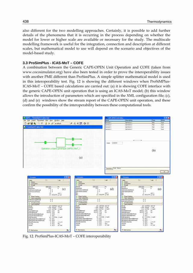
3.3 ProSimPlus - ICAS-MoT – COFE A combination between the Generic CAPE-OPEN Unit Operation and COFE (taken from www.cocosimulator.org) have also been tested in order to prove the interoperability issues with another PME different than ProSimPlus. A simple splitter mathematical model is used in this interoperability test. Fig. 12 is showing the different windows when ProSiMPlus-ICAS-MoT – COFE based calculations are carried out: (a) it is showing COFE interface with the generic CAPE-OPEN unit operation that is using an ICAS-MoT model; (b) this window allows the introduction of parameters which are specified in the XML configuration file; (c), (d) and (e) windows show the stream report of the CAPE-OPEN unit operation, and these confirm the possibility of the interoperability between these computational tools.
Fig. 12. ProSimPlus-ICAS-MoT – COFE interoperability

Interoperability between Modelling Tools (MoT) with Thermodynamic Property Prediction Packages (Simulis® Thermodynamics) and Process Simulators (ProSimPlus) Via CAPE-OPEN Standards
439
Note that the use of the CAPE-OPEN standards facilitates the simulation of new unit operations in PMEs or those that cannot be found in commercial simulators. The use of the multiscale modelling approach embedded in the model of the new unit operation is used to highlight the importance of selecting the appropriate details of the model needed to match the objective. Other examples for chemical product-process design have been solved in a software so called the Virtual Product-Process Design Lab, which also combines different computer-aided tools through the use of COM-objects (Morales-Rodriguez, 2009; Morales-Rodriguez & Gani, 2009).
4. Conclusion The advantages of the use of CAPE-OPEN standards for the integration of different tools have been tested and highlighted. Furthermore, the use of a multiscale modelling approach in the simulation of unit operations not found in the host PME has been highlighted for different scales and objectives of the model. Using a standard middleware for thermo-models interoperability aspects of the integrated tools have been illustrated through the calculation of fugacity coefficients and activity coefficients by different property models. The integration between ICAS-MoT and ProSimPlus for reliable simulation of any unit operation, where models can be supplied from different sources can be easily achieved through plug & play (interoperability) of software tools and models. Here, the CAPE-OPEN interface for unit operations plays an important role. Current and future work is involved with the development and testing of more middleware and in the creation of a library of models ready to be used through the developed CAPE-OPEN compliant middleware.
5. References Barrett Jr, W.M. & Yang, J. (2005). Development of a chemical process modelling
environment based on CAPE-OPEN interfaces standards and the Microsoft .NET framework. Computers and Chemical Engineering, Vol. 30, No. 2, 191-201. ISSN 0098-1354.
Belaud, J.P. & Pons, M. (2002). Open software for process simulation: the current status of CAPE-OPEN standard. Computer-Aided Chemical Engineering, vol. 10, in Grievink, J. and van Schijndel, J. (eds). European Symposium on Computer Aided Process Engineering – 12, (Elsevier, Amsterdam, Netherlands). ISBN 10: 0-444-51109-1.
Braunschweig, B.L., Pantelides, C.C., Britt, H.I. & Sama, S. (2000). Process modelling: The promise of open software architectures. Chemical Engineering Progress. Vol. 96, 65-76. ISSN 0360-7275.
Cameron, I.T., & Gani, R. (2010). Product and Process Modelling: A Case Study Approach. Elsevier Science.ISBN 13: 978-0444531612.
Cameron, I.T., Wang, F.Y., Immanuel, C.D. & Stepanek, F. (2005). Process system modelling and applications in granulation: A review. Chemical Engineering Science, Vol. 60, No. 14, 3723-3750. ISSN 0009-2509.

Thermodynamics
440
Morales-Rodriguez, R. (2009). Computer-Aided multiscale Modelling for Chemical Product-Process Design. Department of Chemical and Biochemical Engineering, Technical University of Denmark. ISBN: 978-87-92481-01-6.
Morales-Rodriguez, R. & Gani, R. (2007). Multiscale Modelling Framework for Chemical Product-Process Design. Computer-Aided Chemical Engineering, Vol. 26. ISSN 1570-7946.
Morales-Rodriguez, R., Sales-Cruz, M., Gani, R., Déchelotte, S., Vacher, A. & Baudouin, O. (2007). Interoperability between modelling tools (MoT) and process simulators (ProSim) through CAPE-OPEN standards, Paper489c, Presented at AIChE Annual Meeting, San Francisco, 12-17 November.
Pons, M. (2003). Industrial implementations of the CAPE-OPEN standard. In AIDIC Conference Series, Vol 6, 253-262. ISBN 0390-2358.
Pons, M. (2005a). What is the CAPE-OPEN Laboratories Network (CO-LaN)?. Chemical Processing. Available at: http://www.chemicalprocessing.com/
Pons, M. (2005b). Introduction to CAPE-OPEN part 1, Presentation in Scandpower, June 14. At: http://www.colan.org/Communication/Y05_SPTGroup_Introduction.pdf
Sundmacher, K., Schultz, T., Zhou, S., Scott, K., Ginkel, M. & Gilles, E.D. (2001). Dynamics of the direct methanol fuel cell (DMFC): experiments and model based analysis. Chemical Engineering Science, Vol. 56, No. 2, 333-341. ISSN 0009-2509.
Xu, C., Follmann, P.M. Biegler, L.T. & Jhon, M.S. (2005). Numerical simulation and optimization of a direct methanol fuel cell. Computers and Chemical Engineering, Vol. 29, No. 8, 1849-1860. ISSN 0098-1354.