Embed Size (px)
Citation preview

C H A P T E R
Internetworking Design Basic
2
Internetworking Design Basics
Designing an internetwork can be a challenging task. An internetwork that consists of only50 meshed routing nodes can pose complex problems that lead to unpredictable results. Attemptingto optimize internetworks that feature thousands of nodes can pose even more complex problems.
Despite improvements in equipment performance and media capabilities, internetwork design isbecoming more difficult. The trend is toward increasingly complex environments involving multiplemedia, multiple protocols, and interconnection to networks outside any single organization’sdominion of control. Carefully designing internetworks can reduce the hardships associated withgrowth as a networking environment evolves.
This chapter provides an overview of planning and design guidelines. Discussions are divided intothe following general topics:
• Understanding Basic Internetworking Concepts
• Identifying and Selecting Internetworking Capabilities
• Identifying and Selecting Internetworking Devices
Understanding Basic Internetworking ConceptsThis section covers the following basic internetworking concepts:
• Overview of Internetworking Devices
• Switching Overview
Overview of Internetworking DevicesNetwork designers faced with designing an internetwork have four basic types of internetworkingdevices available to them:
• Hubs (concentrators)
• Bridges
• Switches
• Routers
Table 2-1 summarizes these four internetworking devices.
s 2-1

Understanding Basic Internetworking Concepts
chal as
direct
Table 2-1 Summary of Internetworking Devices
Data communications experts generally agree that network designers are moving away from bridgesand concentrators and primarily using switches and routers to build internetworks. Consequently,this chapter focuses primarily on the role of switches and routers in internetwork design.
Switching OverviewToday in data communications, all switching and routing equipment perform two basic operations:
• Switching data frames—This is generally a store-and-forward operation in which a frame arriveson an input media and is transmitted to an output media.
• Maintenance of switching operations—In this operation, switches build and maintain switchingtables and search for loops. Routers build and maintain both routing tables and service tables.
There are two methods of switching data frames: Layer 2 and Layer 3 switching.
Layer 2 and Layer 3 SwitchingSwitching is the process of taking an incoming frame from one interface and delivering it outthrough another interface. Routers use Layer 3 switching to route a packet, and switches (Layer 2switches) use Layer 2 switching to forward frames.
The difference between Layer 2 and Layer 3 switching is the type of information inside the framethat is used to determine the correct output interface. With Layer 2 switching, frames areswitched based on MAC address information. With Layer 3 switching, frames are switched basedon network-layer information.
Layer 2 switching does not look inside a packet for network-layer information as does Layer 3switching. Layer 2 switching is performed by looking at a destination MAC address within a frame.It looks at the frame’s destination address and sends it to the appropriate interface if it knows thedestination address location. Layer 2 switching builds and maintains a switching table that keepstrack of which MAC addresses belong to each port or interface.
If the Layer 2 switch does not know where to send the frame, it broadcasts the frame out all its portsto the network to learn the correct destination. When the frame’s reply is returned, the switch learnsthe location of the new address and adds the information to the switching table.
Device Description
Hubs (concentrators) Hubs (concentrators) are used to connect multiple users to a single physical device, whiconnects to the network. Hubs and concentrators act as repeaters by regenerating the signit passes through them.
Bridges Bridges are used to logically separate network segments within the same network. Theyoperate at the OSI data link layer (Layer 2) and are independent of higher-layer protocols.
Switches Switches are similar to bridges but usually have more ports. Switches provide a uniquenetwork segment on each port, thereby separating collision domains. Today, networkdesigners are replacing hubs in their wiring closets with switches to increase their networkperformance and bandwidth while protecting their existing wiring investments.
Routers Routers separate broadcast domains and are used to connect different networks. Routersnetwork traffic based on the destination network layer address (Layer 3) rather than theworkstation data link layer or MAC address. Routers are protocol dependent.
Internetwork Design Guide2-2

Switching Overview
Layer 2 addresses are determined by the manufacturer of the data communications equipment used.They are unique addresses that are derived in two parts: the manufacturing (MFG) code and theunique identifier. The MFG code is assigned to each vendor by the IEEE. The vendor assigns aunique identifier to each board it produces. Except for Systems Network Architecture (SNA)networks, users have little or no control over Layer 2 addressing because Layer 2 addresses are fixedwith a device, whereas Layer 3 addresses can be changed. In addition, Layer 2 addresses assume aflat address space with universally unique addresses.
Layer 3 switching operates at the network layer. It examinespacket information and forwardspackets based on their network-layer destination addresses. Layer 3 switching also supports routerfunctionality.
For the most part, Layer 3 addresses are determined by the network administrator who installs ahierarchy on the network. Protocols such as IP, IPX, and AppleTalk use Layer 3 addressing. Bycreating Layer 3 addresses, a network administrator creates local areas that act as single addressingunits (similar to streets, cities, states, and countries), and assigns a number to each local entity. Ifusers move to another building, their end stations will obtain new Layer 3 addresses, but their Layer2 addresses remain the same.
As routers operate at Layer 3 of the OSI model, they can adhere to and formulate a hierarchicaladdressing structure. Therefore, a routed network can tie a logical addressing structure to a physicalinfrastructure, for example, through TCP/IP subnets or IPX networks for each segment. Traffic flowin a switched (flat) network is therefore inherently different from traffic flow in a routed(hierarchical) network. Hierarchical networks offer more flexible traffic flow than flat networksbecause they can use the network hierarchy to determine optimal paths and contain broadcastdomains.
Implications of Layer 2 and Layer 3 SwitchingThe increasing power of desktop processors and the requirements of client-server and multimediaapplications have driven the need for greater bandwidth in traditional shared-media environments.These requirements are prompting network designers to replace hubs in wiring closets withswitches.
Although Layer 2 switches use microsegmentation to satisfy the demands for more bandwidth andincreased performance, network designers are now faced with increasing demands for intersubnetcommunication. For example, every time a user accesses servers and other resources, which arelocated on different subnets, the traffic must go through a Layer 3 device. Figure 2-1 shows the routeof intersubnet traffic with Layer 2 switches and Layer 3 switches.
Figure 2-1 Flow of intersubnet traffic with Layer 2 switches and routers.
As Figure 2-1 shows, for Client X to communicate with Server Y, which is on another subnet, it musttraverse through the following route: first through Switch A (a Layer 2 switch) and then throughRouter A (a Layer 3 switch) and finally through Switch B (a Layer 2 switch). Potentially there is atremendous bottleneck, which can threaten network performance, because the intersubnet trafficmust pass from one network to another.
Router ALayer 3 switch
Switch ALayer 2 switch
Client XSubnet 1
Switch BLayer 2 switch
Server YSubnet 2
Internetworking Design Basics 2-3

Identifying and Selecting Internetworking Capabilities
To relieve this bottleneck, network designers can add Layer 3 capabilities throughout the network.They are implementing Layer 3 switching on edge devices to alleviate the burden on centralizedrouters. Figure 2-2 illustrates how deploying Layer 3 switching throughout the network allowsClient X to directly communicate with Server Y without passing through Router A.
Figure 2-2 Flow of intersubnet traffic with Layer 3 switches.
Identifying and Selecting Internetworking CapabilitiesAfter you understand your internetworking requirements, you must identify and then select thespecific capabilities that fit your computing environment. The following discussions provide astarting point for making these decisions:
• Identifying and Selecting an Internetworking Model
• Choosing Internetworking Reliability Options
Identifying and Selecting an Internetworking ModelHierarchical models for internetwork design allow you to design internetworks in layers. Tounderstand the importance of layering, consider the Open System Interconnection (OSI) referencemodel, which is a layered model for understanding and implementing computer communications.By using layers, the OSI model simplifies the task required for two computers to communicate.Hierarchical models for internetwork design also uses layers to simplify the task required forinternetworking. Each layer can be focused on specific functions, thereby allowing the networkingdesigner to choose the right systems and features for the layer.
Using a hierarchical design can facilitate changes. Modularity in network design allows you to createdesign elements that can be replicated as the network grows. As each element in the network designrequires change, the cost and complexity of making the upgrade is constrained to a small subset ofthe overall network. In large flat or meshed network architectures, changes tend to impact a largenumber of systems. Improved fault isolation is also facilitated by modular structuring of the networkinto small, easy-to-understand elements. Network mangers can easily understand the transitionpoints in the network, which helps identify failure points.
Using the Hierarchical Design ModelA hierarchical network design includes the following three layers:
Switch BLayer 2 and 3 switch
Router A
Client X
Switch ALayer 2 and 3 switching
Switch CLayer 2 and 3 switching
Server Y
Si
SiSi
Internetwork Design Guide2-4

Using the Hierarchical Design Model
• The backbone (core) layer that provides optimal transport between sites
• The distribution layer that provides policy-based connectivity
• The local-access layer that provides workgroup/user access to the network
Figure 2-3 shows a high-level view of the various aspects of a hierarchical network design. Ahierarchical network design presents three layers—core, distribution, and access—with each layerproviding different functionality.
Figure 2-3 Hierarchical network design model.
Function of the Core LayerThe core layer is a high-speed switching backbone and should be designed to switch packets as fastas possible. This layer of the network should not perform any packet manipulation, such as accesslists and filtering, that would slow down the switching of packets.
Function of the Distribution LayerThe distribution layer of the network is the demarcation point between the access and core layersand helps to define and differentiate the core. The purpose of this layer is to provide boundarydefinition and is the place at which packet manipulation can take place. In the campus environment,the distribution layer can include several functions, such as the following:
• Address or area aggregation
• Departmental or workgroup access
• Broadcast/multicast domain definition
• Virtual LAN (VLAN) routing
• Any media transitions that need to occur
• Security
In the non-campus environment, the distribution layer can be a redistribution point between routingdomains or the demarcation between static and dynamic routing protocols. It can also be the pointat which remote sites access the corporate network. The distribution layer can be summarized as thelayer that provides policy-based connectivity.
Core
High-speed switching
Policy-based connectivity
Distribution
Access
Local and remote workgroup access
Internetworking Design Basics 2-5

Identifying and Selecting Internetworking Capabilities
Function of the Access LayerThe access layer is the point at which local end users are allowed into the network. This layer mayalso use access lists or filters to further optimize the needs of a particular set of users. In the campusenvironment, access-layer functions can include the following:
• Shared bandwidth
• Switched bandwidth
• MAC layer filtering
• Microsegmentation
In the non-campus environment, the access layer can give remote sites access to the corporatenetwork via some wide-area technology, such as Frame Relay, ISDN, or leased lines.
It is sometimes mistakenly thought that the three layers (core, distribution, and access) must exist inclear and distinct physical entities, but this does not have to be the case. The layers are defined to aidsuccessful network design and to represent functionality that must exist in a network. Theinstantiation of each layer can be in distinct routers or switches, can be represented by a physicalmedia, can be combined in a single device, or can be omitted altogether. The way the layers areimplemented depends on the needs of the network being designed. Note, however, that for a networkto function optimally, hierarchy must be maintained.
The discussions that follow outline the capabilities and services associated with backbone,distribution, and local access internetworking services.
Evaluating Backbone ServicesThis section addresses internetworking features that support backbone services. The followingtopics are discussed:
• Path Optimization
• Traffic Prioritization
• Load Balancing
• Alternative Paths
• Switched Access
• Encapsulation (Tunneling)
Path OptimizationOne of the primary advantages of a router is its capability to help you implement a logicalenvironment in which optimal paths for traffic are automatically selected. Routers rely on routingprotocols that are associated with the various network layer protocols to accomplish this automatedpath optimization.
Depending on the network protocols implemented, routers permit you to implement routingenvironments that suit your specific requirements. For example, in an IP internetwork, Cisco routerscan support all widely implemented routing protocols, including Open Shortest Path First (OSPF),RIP, IGRP, Border Gateway Protocol (BGP), Exterior Gateway Protocol (EGP), and HELLO. Keybuilt-in capabilities that promote path optimization include rapid and controllable route convergenceand tunable routing metrics and timers.
Internetwork Design Guide2-6

Evaluating Backbone Services
Convergence is the process of agreement, by all routers, on optimal routes. When a network eventcauses routes to either halt operation or become available, routers distribute routing updatemessages. Routing update messages permeate networks, stimulating recalculation of optimal routesand eventually causing all routers to agree on these routes. Routing algorithms that converge slowlycan cause routing loops or network outages.
Many different metrics are used in routing algorithms. Some sophisticated routing algorithms baseroute selection on a combination of multiple metrics, resulting in the calculation of a single hybridmetric. IGRP uses one of the most sophisticated distance vector routing algorithms. It combinesvalues for bandwidth, load, and delay to create a composite metric value. Link state routingprotocols, such as OSPF and IS-IS, employ a metric that represents the cost associated with a givenpath.
Traffic PrioritizationAlthough some network protocols can prioritize internal homogeneous traffic, the router prioritizesthe heterogeneous traffic flows. Such traffic prioritization enables policy-based routing and ensuresthat protocols carrying mission-critical data take precedence over less important traffic.
Priority QueuingPriority queuing allows the network administrator to prioritize traffic. Traffic can be classifiedaccording to various criteria, including protocol and subprotocol type, and then queued on one offour output queues (high, medium, normal, or low priority). For IP traffic, additional fine-tuning ispossible. Priority queuing is most useful on low-speed serial links. Figure 2-4 shows how priorityqueuing can be used to segregate traffic by priority level, speeding the transit of certain packetsthrough the network.
Figure 2-4 Priority queuing.
You can also use intraprotocol traffic prioritization techniques to enhance internetworkperformance. IP’s type-of-service (TOS) feature and prioritization of IBM logical units (LUs)are intraprotocol prioritization techniques that can be implemented to improve traffic handling overrouters. Figure 2-5 illustrates LU prioritization.
Traffic sent to routerwithout any priority
UDPBridged LAT
DECnetVINESTCPOther bridged
All other traffic
AppleTalk
Traffic Priority
High priority
Mediumpriority
Normalpriority
Lowpriority
Backbonenetwork
Traffic sent tobackbone in
order of priority
Router
Internetworking Design Basics 2-7
Identifying and Selecting Internetworking Capabilities
Figure 2-5 LU prioritization implementation.
In Figure 2-5, the IBM mainframe is channel-attached to a 3745 communications controller, whichis connected to a 3174 cluster controller via remote source-route bridging (RSRB). Multiple 3270terminals and printers, each with a unique local LU address, are attached to the 3174. By applyingLU address prioritization, you can assign a priority to each LU associated with a terminal or printer;that is, certain users can have terminals that have better response time than others, and printers canhave lowest priority. This function increases application availability for those users runningextremely important applications.
Finally, most routed protocols (such as AppleTalk, IPX, and DECnet) employ a cost-based routingprotocol to assess the relative merit of the different routes to a destination. By tuning associatedparameters, you can force particular kinds of traffic to take particular routes, thereby performing atype of manual traffic prioritization.
Custom QueuingPriority queuing introduces a fairness problem in that packets classified to lower priority queuesmight not get serviced in a timely manner, or at all. Custom queuing is designed to address thisproblem. Custom queuing allows more granularity than priority queuing. In fact, this feature iscommonly used in the internetworking environment in which multiple higher-layer protocols aresupported. Custom queuing reserves bandwidth for a specific protocol, thus allowing mission-critical traffic to receive a guaranteed minimum amount of bandwidth at any time.
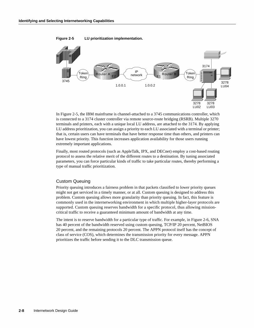
The intent is to reserve bandwidth for a particular type of traffic. For example, in Figure 2-6, SNAhas 40 percent of the bandwidth reserved using custom queuing, TCP/IP 20 percent, NetBIOS20 percent, and the remaining protocols 20 percent. The APPN protocol itself has the concept ofclass of service (COS), which determines the transmission priority for every message. APPNprioritizes the traffic before sending it to the DLC transmission queue.
TokenRing
37451.0.0.21.0.0.1
IPnetwork Token
Ring
3278LU03
3278LU02
3174
3278LU04
Router AE2
Router BE1
Internetwork Design Guide2-8
Evaluating Backbone Services
Figure 2-6 Custom queuing.
Custom queuing prioritizes multiprotocol traffic. A maximum of 16 queues can be built with customqueuing. Each queue is serviced sequentially until the number of bytes sent exceeds the configurablebyte count or the queue is empty. One important function of custom queuing is that if SNA trafficuses only 20 percent of the link, the remaining 20 percent allocated to SNA can be shared by theother traffic.
Custom queuing is designed for environments that want to ensure a minimum level of service for allprotocols. In today’s multiprotocol internetwork environment, this important feature allowsprotocols of different characteristics to share the media.
Weighted Fair QueuingWeighted fair queuing is a traffic priority management algorithm that uses the time-divisionmultiplexing (TDM) model to divide the available bandwidth among clients that share the sameinterface. In time-division multiplexing, each client is allocated a time slice in a round-robin fashion.In weighted fair queuing, the bandwidth is distributed evenly among clients so that each client getsa fair share if every one has the same weighting. You can assign a different set of weights, forexample through type-of-service, so that more bandwidth is allocated.
If every client is allocated the same bandwidth independent of the arrival rates, the low volume traffichas effective priority over high volume traffic. The use of weighting allows time-delay-sensitivetraffic to obtain additional bandwidth, thus consistent response time is guaranteed under heavytraffic. There are different types of data stream converging on a wire, as shown in Figure 2-7.
S
S
S
S S S
TCP/IPtraffic
T T 20%
APPNtraffic
A A
40%
NetBIOStraffic
N
M N A T S S
N 20%
Miscellaneoustraffic
M M M 20%
H
M
H
L
N H M
N = Network priority
H = High priority
M = Medium priority
L = Low priority
S = SNA traffic
L
Internetworking Design Basics 2-9

Identifying and Selecting Internetworking Capabilities
Figure 2-7 Weighted fair queuing.
Both C and E are FTP sessions, and they are high-volume traffic. A, B, and D are interactive sessionsand they are low-volume traffic. Every session in this case is termed aconversation. If eachconversation is serviced in a cyclic manner and gets a slot regardless of its arrival rate, the FTPsessions do not monopolize the bandwidth. Round trip delays for the interactive traffic, therefore,become predictable.
Weighted fair queuing provides an algorithm to identify data streams dynamically using an interface,and sorts them into separate logical queues. The algorithm uses various discriminators based onwhatever network layer protocol information is available and sorts among them. For example, for IPtraffic, the discriminators are source and destination address, protocol type, socket numbers, andTOS. This is how the two Telnet sessions (Sessions B and D) are assigned to different logical queues,as shown in Figure 2-7.
Ideally, the algorithm would classify every conversation that is sharing the wire so that eachconversation receives its fair share of the bandwidth. Unfortunately, with such protocols as SNA, youcannot distinguish one SNA session from another. For example, in DLSw+, SNA traffic ismultiplexed onto a single TCP session. Similarly in APPN, SNA sessions are multiplexed onto asingle LLC2 session.
The weighted fair queuing algorithm treats these sessions as a single conversation. If you have manyTCP sessions, the TCP sessions get the majority of the bandwidth and the SNA traffic gets theminimum. For this reason, this algorithm is not recommended for SNA using DLSw+ TCP/IPencapsulation and APPN.
Weighted fair queuing, however, has many advantages over priority queuing and custom queuing.Priority queuing and custom queuing require the installation of access lists; the bandwidth has to bepre-allocated and priorities have to be predefined. This is clearly a burden. Sometimes, networkadministrators cannot identify and prioritize network traffic in real time. Weighted fair queuing sortsamong individual traffic streams without the administrative burden associated with the other twotypes of queuing.
Load BalancingThe easiest way to add bandwidth in a backbone network is to implement additional links. Routersprovide built-in load balancing for multiple links and paths. You can use up to four paths to adestination network. In some cases, the paths need not be of equal cost.
Within IP, routers provide load balancing on both a per-packet and a per-destination basis. Forper-destination load balancing, each router uses its route cache to determine the output interface. IfIGRP or Enhanced IGRP routing is used, unequal-cost load balancing is possible. The router usesmetrics to determine which paths the packets will take; the amount of load balancing can be adjustedby the user.
Telnet session BB B B B
IPX session AA A A A
FTP session C
CCCCCCC C
Telnet session DD
B A B D C E A
DFTP session E
EEEEEE E E
Internetwork Design Guide2-10

Evaluating Backbone Services
Load balancing bridged traffic over serial lines is also supported. Serial lines can be assigned tocircuit groups. If one of the serial links in the circuit group is in the spanning tree for a network, anyof the serial links in the circuit group can be used for load balancing. Data ordering problems areavoided by assigning each destination to a serial link. Reassignment is done dynamically if interfacesgo down or come up.
Alternative PathsMany internetwork backbones carry mission-critical information. Organizations running suchbackbones are usually interested in protecting the integrity of this information at virtually any cost.Routers must offer sufficient reliability so that they are not the weak link in the internetwork chain.The key is to provide alternative paths that can come on line whenever link failures occur alongactive networks.
End-to-end reliability is not ensured simply by making the backbone fault tolerant. Ifcommunication on a local segment within any building is disrupted for any reason, that informationwill not reach the backbone. End-to-end reliability is only possible when redundancy is employedthroughout the internetwork. Because this is usually cost prohibitive, most companies prefer toemploy redundant paths only on those segments that carry mission-critical information.
What does it take to make the backbone reliable? Routers hold the key to reliable internetworking.Depending on the definition of reliability, this can mean duplicating every major system on eachrouter and possibly every component. However, hardware component duplication is not the entiresolution because extra circuitry is necessary to link the duplicate components to allow them tocommunicate. This solution is usually very expensive, but more importantly, it does not completelyaddress the problem. Even assuming all routers in your network are completely reliable systems, linkproblems between nodes within a backbone can still defeat a redundant hardware solution.
To really address the problem of network reliability,links must be redundant. Further, it is notenough to simply duplicate all links. Dual links must terminate at multiple routers unless allbackbone routers are completely fault tolerant (no single points of failure). Otherwise, backbonerouters that are not fault tolerant become single points of failure. The inevitable conclusion is that acompletely redundant router is not the most effective solution to the reliability problem because it isexpensive and still does not address link reliability.
Most network designers do not implement a completely redundant network. Instead, networkdesigners implement partially redundant internetworks. The section, “Choosing InternetworkingReliability Options,” later in this chapter, addresses several hypothetical networks that representcommonly implemented points along the reliability continuum.
Switched AccessSwitched access provides the capability to enable a WAN link on an as-needed basis via automatedrouter controls. One model for a reliable backbone consists of dual, dedicated links and one switchedlink for idle hot backup. Under normal operational conditions, you can load balance over the duallinks, but the switched link is not operational until one of the dedicated links fails.
Traditionally, WAN connections over the Public Switched Telephone Network (PSTN) have useddedicated lines. This can be very expensive when an application requires only low-volume, periodicconnections. To reduce the need for dedicated circuits, a feature calleddial-on-demand routing(DDR) is available. Figure 2-8 illustrates a DDR connection.
Internetworking Design Basics 2-11

Identifying and Selecting Internetworking Capabilities
Figure 2-8 The Dial-on-demand routing environment.
Using DDR, low-volume, periodic network connections can be made over the PSTN. A routeractivates the DDR feature when it receives a bridged or routed IP packet destined for a location onthe other side of the dial-up line. After the router dials the destination phone number and establishesthe connection, packets of any supported protocol can be transmitted. When the transmission iscomplete, the line is automatically disconnected. By terminating unneeded connections, DDRreduces cost of ownership.
Encapsulation (Tunneling)Encapsulationtakes packets or frames from one network system and places them inside frames fromanother network system. This method is sometimes calledtunneling. Tunneling provides a meansfor encapsulating packets inside a routable protocol via virtual interfaces. Synchronous Data LinkControl (SDLC) transport is also an encapsulation of packets in a routable protocol. In addition,transport provides enhancements to tunneling, such as local data-link layer termination, broadcastavoidance, media conversion, and other scalability optimizations.
Cisco routers support the following encapsulation and tunneling techniques:
• The IBM technology feature set provides these methods:
— Serial tunneling (STUN) or Synchronous Data Link Control (SDLC) Transport
— SRB with direct encapsulation
— SRB with Fast Sequenced Transport (FST) encapsulation
— SRB with Transmission Control Protocol/Internet Protocol (TCP/IP) encapsulation
— Data Link Switching Plus (DLSw+) with direct encapsulation
— DLSw+ with TCP/IP encapsulation
— DLSw+ with Fast Sequenced Transport/Internet Protocol (FST/IP) encapsulation
— DLSw+ with DLSw Lite (Logical Link Control Type 2 [LLC2]) encapsulation
• Generic Routing Encapsulation (GRE)
Cisco supports encapsulating Novell Internetwork Packet Exchange (IPX), Internet Protocol(IP), Connectionless Network Protocol (CLNP), AppleTalk, DECnet Phase IV, Xerox NetworkSystems (XNS), Banyan Virtual Network System (VINES), and Apollo packets for transportover IP
• Single-protocol tunneling techniques: Cayman (AppleTalk over IP), AURP (AppleTalk over IP),EON (CLNP over IP), and NOS (IP over IP)
The following discussion focuses on IBM encapsulations and the multiprotocol GRE tunnelingfeature.
DCEdevice
DCEdevice
Ethernet
Ethernet
TokenRing
TokenRing
Public Switched
TelephoneNetwork
RouterRouter
Internetwork Design Guide2-12

Evaluating Backbone Services
IBM FeaturesSTUN allows two devices that are normally connected by a direct serial link, using protocolscompliant with SDLC or High-level Data Link Control (HDLC), to be connected through one ormore routers. The routers can be connected via a multiprotocol network of arbitrary topology. STUNallows integration of System Network Architecture (SNA) networks and non-SNA networks usingrouters and existing network links. Transport across the multiprotocol network that connects therouters can use TCP/IP. This type of transport offers reliability and intelligent routing via anysupported IP routing protocol. A STUN configuration is shown in Figure 2-9.
Figure 2-9 STUN configuration.
SDLC Transport is a variation of STUN that allows sessions using SDLC protocols and TCP/IPencapsulation to be locally terminated. SDLC Transport permits participation in SDLC windowingand retransmission activities.
When connecting remote devices that use SRB over a slow-speed serial link, most network designerschoose RSRB with direct HDLC encapsulation. In this case, SRB frames are encapsulated in anHDLC-compliant header. This solution adds little overhead, preserving valuable serial linkbandwidth. Direct HDLC encapsulation is not restricted to serial links (it can also be used overEthernet, Token Ring, and FDDI links), but is most useful in situations in which additional controloverhead on the encapsulating network is not tolerable.
TokenRing
TokenRing
Local site
Remote site
16/4Mbps
16/4Mbps
Sun workstations
3270 3270 3270
IBM terminals
IBM mainframe
Sun workstations
Cluster controller 3x74
SNAbackbone
TokenRing
16/4Mbps
37x5
Router
Router
Router
Router
Internetworking Design Basics 2-13

Identifying and Selecting Internetworking Capabilities
When more overhead can be tolerated, frame sequencing is important, but extremely reliabledelivery is not needed, and SRB packets can be sent over serial, Token Ring, Ethernet, and FDDInetworks using FST encapsulation. FST is similar to TCP in that it provides packet sequencing.However, unlike TCP, FST does not provide packet-delivery acknowledgment.
For extremely reliable delivery in environments in which moderate overhead can be tolerated, youcan choose to encapsulate SRB frames in TCP/IP packets. This solution is not only reliable, it canalso take advantage of routing features that include handling via routing protocols, packet filtering,and multipath routing.
Generic Routing Encapsulation (GRE)Cisco’s Generic Routing Encapsulation (GRE) multiprotocol carrier protocol encapsulates IP,CLNP, IPX, AppleTalk, DECnet Phase IV, XNS, VINES, and Apollo packets inside IP tunnels. WithGRE tunneling, a Cisco router at each site encapsulates protocol-specific packets in an IP header,creating a virtual point-to-point link to Cisco routers at other ends of an IP cloud, where the IP headeris stripped off. By connecting multiprotocol subnetworks in a single-protocol backboneenvironment, IP tunneling allows network expansion across a single-protocol backboneenvironment. GRE tunneling involves three types of protocols:
• Passenger—The protocol is encapsulated (IP, CLNP, IPX, AppleTalk, DECnet Phase IV, XNS,VINES and Apollo).
• Carrier—GRE protocol provides carrier services.
• Transport—IP carries the encapsulated protocol.
GRE tunneling allows desktop protocols to take advantage of the enhanced route selectioncapabilities of IP. Many local-area network (LAN) protocols, including AppleTalk and Novell IPX,are optimized for local use. They have limited route selection metrics and hop count limitations. Incontrast, IP routing protocols allow more flexible route selection and scale better over largeinternetworks. Figure 2-10 illustrates GRE tunneling across a single IP backbone between sites.Regardless of how many routers and paths may be associated with the IP cloud, the tunnel is seen asa single hop.
Figure 2-10 Using a single protocol backbone.
GRE provides key capabilities that other encapsulation protocols lack: sequencing and the capabilityto carry tunneled data at high speeds. Some higher-level protocols require that packets are deliveredin correct order. The GRE sequencing option provides this capability. GRE also has an optional key
AppleTalksite
Novellsite
AppleTalksite
AppleTalk/Novellsite
IPBackbone
GRE tunnel
Internetwork Design Guide2-14

Evaluating Backbone Services
feature that allows you to avoid configuration errors by requiring the same key to be entered at eachtunnel endpoint before the tunneled data is processed. IP tunneling also allows network designers toimplement policies, such as which types of traffic can use which routes or assignment of priority orsecurity levels to particular traffic. Capabilities like these are lacking in many native LAN protocols.
IP tunneling provides communication between subnetworks that have invalid or discontiguousnetwork addresses. With tunneling, virtual network addresses are assigned to subnetworks, makingdiscontiguous subnetworks reachable. Figure 2-11 illustrates that with GRE tunneling, it is possiblefor the two subnetworks of network 131.108.0.0 to talk to each other even though they are separatedby another network.
Figure 2-11 Connecting discontiguous networks with tunnels.
Because encapsulation requires handling of the packets, it is generally faster to route protocolsnatively than to use tunnels. Tunneled traffic is switched at approximately half the typical processswitching rates. This means approximately 1,000 packets per second (pps) aggregate for each router.Tunneling is CPU intensive, and as such, should be turned on cautiously. Routing updates, SAPupdates, and other administrative traffic may be sent over each tunnel interface. It is easy to saturatea physical link with routing information if several tunnels are configured over it. Performancedepends on the passenger protocol, broadcasts, routing updates, and bandwidth of the physicalinterfaces. It is also difficult to debug the physical link if problems occur. This problem can bemitigated in several ways. In IPX environments, route filters and SAP filters cut down on the size ofthe updates that travel over tunnels. In AppleTalk networks, keeping zones small and using routefilters can limit excess bandwidth requirements.
Tunneling can disguise the nature of a link, making it look slower, faster, or more or less costly thanit may actually be in reality. This can cause unexpected or undesirable route selection. Routingprotocols that make decisions based only on hop count will usually prefer a tunnel to a real interface.This may not always be the best routing decision because an IP cloud can comprise several differentmedia with very disparate qualities; for example, traffic may be forwarded across both 100-MbpsEthernet lines and 9.6-Kbps serial lines. When using tunneling, pay attention to the media overwhich virtual tunnel traffic passes and the metrics used by each protocol.
If a network has sites that use protocol-based packet filters as part of a firewall security scheme, beaware that because tunnels encapsulate unchecked passenger protocols, you must establish filteringon the firewall router so that only authorized tunnels are allowed to pass. If tunnels are accepted fromunsecured networks, it is a good idea to establish filtering at the tunnel destination or to place thetunnel destination outside the secure area of your network so that the current firewall scheme willremain secure.
131.108.20.0255.255.255.0
131.108.10.0255.255.255.0
Tunnel
Network192.1.1.0
Router Router
Internetworking Design Basics 2-15

Identifying and Selecting Internetworking Capabilities
When tunneling IP over IP, you must be careful to avoid inadvertently configuring a recursive routingloop. A routing loop occurs when the passenger protocol and the transport protocol are identical. Therouting loop occurs because the best path to the tunnel destination is via the tunnel interface. Arouting loop can occur when tunneling IP over IP, as follows:
1 The packet is placed in the output queue of the tunnel interface.
2 The tunnel interface includes a GRE header and enqueues the packet to the transport protocol (IP)for the destination address of the tunnel interface.
3 IP looks up the route to the tunnel destination address and learns that the path is the tunnelinterface.
4 Once again, the packet is placed in the output queue of the tunnel interface, as described inStep 1, hence, the routing loop.
When a router detects a recursive routing loop, it shuts down the tunnel interface for 1 to 2 minutesand issues a warning message before it goes into the recursive loop. Another indication that arecursive route loop has been detected is if the tunnel interface is up and the line protocol is down.
To avoid recursive loops, keep passenger and transport routing information in separate locations byimplementing the following procedures:
• Use separate routing protocol identifiers (for example, igrp 1 and igrp 2).
• Use different routing protocols.
• Assign the tunnel interface a very low bandwidth so that routing protocols, such as IGRP, willrecognize a very high metric for the tunnel interface and will, therefore, choose the correct nexthop (that is, choose the best physical interface instead of the tunnel).
• Keep the two IP address ranges distinct; that is, use a major address for your tunnel network thatis different from your actual IP network. Keeping the address ranges distinct also aids indebugging because it is easy to identify an address as the tunnel network instead of the physicalnetwork and vice versa.
Evaluating Distribution ServicesThis section addresses internetworking features that support distribution services. The followingtopics are discussed:
• Backbone Bandwidth Management
• Area and Service Filtering
• Policy-Based Distribution
• Gateway Service
• Interprotocol Route Redistribution
• Media Translation
Backbone Bandwidth ManagementTo optimize backbone network operations, routers offer several performance tuning features.Examples include priority queuing, routing protocol metrics, and local session termination.
Internetwork Design Guide2-16

Evaluating Distribution Services
You can adjust the output queue length on priority queues. If a priority queue overflows, excesspackets are discarded and quench messages that halt packet flow are sent, if appropriate, for thatprotocol. You can also adjust routing metrics to increase control over the paths that the traffic takesthrough the internetwork.
Local session termination allows routers to act as proxies for remote systems that represent sessionendpoints. (Aproxy is a device that acts on behalf of another device.) Figure 2-12 illustrates anexample of local session termination in an IBM environment.
Figure 2-12 Local session termination over multiprotocol backbone.
In Figure 2-12, the routers locally terminate Logical Link Control type 2 (LLC2) data-link controlsessions. Instead of end-to-end sessions, during which all session control information is passed overthe multiprotocol backbone, the routers take responsibility for acknowledging packets that comefrom hosts on directly attached LANs. Local acknowledgment saves WAN bandwidth (and,therefore, WAN utilization costs), solves session timeout problems, and provides faster response tousers.
Area and Service FilteringTraffic filters based onareaor servicetype are the primary distribution service tools used to providepolicy-based access control into backbone services. Both area and service filtering are implementedusingaccess lists. An access list is a sequence of statements, each of which either permits or deniescertain conditions or addresses. Access lists can be used to permit or deny messages from particularnetwork nodes and messages sent using particular protocols and services.
Area or network access filters are used to enforce the selective transmission of traffic based onnetwork address. You can apply these on incoming or outgoing ports. Service filters use access listsapplied to protocols (such as IP’s UDP), applications such as the Simple Mail Transfer Protocol(SMTP), and specific protocols.
Suppose you have a network connected to the Internet, and you want any host on an Ethernet to beable to form TCP connections to any host on the Internet. However, you do not want Internet hoststo be able to form TCP connections to hosts on the Ethernet except to the SMTP port of a dedicatedmail host.
SMTP uses TCP port 25 on one end of the connection and a random port number on the other end.The same two port numbers are used throughout the life of the connection. Mail packets coming infrom the Internet will have a destination port of 25. Outbound packets will have the port numbers
TokenRing
TokenRing
Multiprotocolbackbone
3x74 controller
Acknowledgments
LLC2 sessionT1 timer
Acknowledgments
LLC2 sessionT1 timer
3745 TCP/IP session• Reliable transport• TCP flow control• Error recovery
Router Router
Internetworking Design Basics 2-17

Identifying and Selecting Internetworking Capabilities
reversed. The fact that the secure system behind the router always accepts mail connections onport 25 is what makes it possible to separately control incoming and outgoing services. The accesslist can be configured on either the outbound or inbound interface.
In the following example, the Ethernet network is a Class B network with the address 128.88.0.0,and the mail host’s address is 128.88.1.2.The keywordestablishedis used only for the TCP protocolto indicate an established connection. A match occurs if the TCP datagram has the ACK or RST bitsset, which indicate that the packet belongs to an existing connection.
access-list 102 permit tcp 0.0.0.0 255.255.255.255 128.88.0.0 0.0.255.255 establishedaccess-list 102 permit tcp 0.0.0.0 255.255.255.255 128.88.1.2 0.0.0.0 eq 25interface ethernet 0ip access-group 102
Policy-Based DistributionPolicy-based distribution is based on the premise that different departments within a commonorganization might have different policies regarding traffic dispersion through the organization-wideinternetwork. Policy-based distribution aims to meet the differing requirements withoutcompromising performance and information integrity.
A policy within this internetworking context is a rule or set of rules that governs end-to-enddistribution of traffic to (and subsequently through) a backbone network. One department might sendtraffic representing three different protocols to the backbone, but might want to expedite oneparticular protocol’s transit through the backbone because it carries mission-critical applicationinformation. To minimize already excessive internal traffic, another department might want toexclude all backbone traffic except electronic mail and one key custom application from entering itsnetwork segment.
These examples reflect policies specific to a single department. However, policies can reflect overallorganizational goals. For example, an organization might want to regulate backbone traffic to amaximum of 10 percent average bandwidth during the work day and 1-minute peaks of 30 percentutilization. Another corporate policy might be to ensure that communication between two remotedepartments can freely occur, despite differences in technology.
Different policies frequently require different workgroup and department technologies. Therefore,support for policy-based distribution implies support for the wide range of technologies currentlyused to implement these policies. This in turn allows you to implement solutions that support a widerange of policies, which helps to increase organizational flexibility and application availability.
In addition to support for internetworking technologies, there must be a means both to keep separateand integrate these technologies, as appropriate. The different technologies should be able to coexistor combine intelligently, as the situation warrants.
Consider the situation depicted in Figure 2-13. Assume that a corporate policy limits unnecessarybackbone traffic. One way to do this is to restrict the transmission of Service Advertisement Protocol(SAP) messages. SAP messages allow NetWare servers to advertise services to clients. Theorganization might have another policy stating that all NetWare services should be provided locally.If this is the case, there should be no reason for services to be advertised remotely. SAP filters preventSAP traffic from leaving a router interface, thereby fulfilling this policy.
Internetwork Design Guide2-18

Evaluating Distribution Services
Figure 2-13 Policy-based distributation: SAP filtering.
Gateway ServiceProtocol gateway capabilities are part of each router’s standard software. For example, DECnet iscurrently in Phase V. DECnet Phase V addresses are different than DECnet Phase IV addresses. Forthose networks that require both type of hosts to coexist, two-way Phase IV/Phase V translationconforms to Digital-specified guidelines. The routers interoperate with Digital routers, and Digitalhosts do not differentiate between the different devices.
The connection of multiple independent DECnet networks can lead to addressing problems. Nothingprecludes two independent DECnet administrators from assigning node address 10 to one of thenodes in their respective networks. When the two networks are connected at some later time,conflicts result. DECnet address translation gateways (ATGs) address this problem. The ATGsolution provides router-based translation between addresses in two different DECnet networksconnected by a router. Figure 2-14 illustrates an example of this operation.
Figure 2-14 Sample DECnet ATG implementation.
In Network 0, the router is configured at address 19.4 and is a Level 1 router. In Network 1, the routeris configured at address 50.5 and is an area router. At this point, no routing information is exchangedbetween the two networks. The router maintains a separate routing table for each network. Byestablishing a translation map, packets in Network 0 sent to address 19.5 will be routed toNetwork 1, and the destination address will be translated to 50.1. Similarly, packets sent toaddress 19.6 in Network 0 will be routed to Network 1 as 19.1; packets sent to address 47.1 inNetwork 1 will be routed to Network 0 as 19.1; and packets sent to 47.2 in Network 1 will be sentto Network 0 as 19.3.
Backbonenetwork
Client Client Client Client Client Client
SAP filter SAP filter
NetWare server NetWare server
Router Router
Network 0 Network 1
19.5 50.1
19.6 19.1
19.1 47.1
19.3 47.2
19.1A::
19.2B::
19.3C::
50.1D::
60.1E::
19.1F::
DECnet translation table
19.4 50.5
Router A
E0 E1
Internetworking Design Basics 2-19

Identifying and Selecting Internetworking Capabilities
AppleTalk is another protocol with multiple revisions, each with somewhat different addressingcharacteristics. AppleTalk Phase 1 addresses are simple local forms; AppleTalk Phase 2 usesextended (multinetwork) addressing. Normally, information sent from a Phase 2 node cannot beunderstood by a Phase 1 node if Phase 2 extended addressing is used. Routers support routingbetween Phase 1 and Phase 2 nodes on the same cable by using transitional routing.
You can accomplish transitional routing by attaching two router ports to the same physical cable.Configure one port to support nonextended AppleTalk and the other to support extended AppleTalk.Both ports must have unique network numbers. Packets are translated and sent out the other port asnecessary.
Interprotocol Route RedistributionThe preceding section, “Gateway Service,” discussed howrouted protocol gateways (such as onethat translates between AppleTalk Phase 1 and Phase 2) allow two end nodes with differentimplementations to communicate. Routers can also act as gateways forrouting protocols.Information derived from one routing protocol, such as the IGRP, can be passed to, and used by,another routing protocol, such as RIP. This is useful when running multiple routing protocols in thesame internetwork.
Routing information can be exchanged between any supported IP routing protocols. These includeRIP, IGRP, OSPF, HELLO, EGP, and BGP. Similarly, route redistribution is supported by ISO CLNSfor route redistribution between ISO IGRP and IS-IS. Static route information can also beredistributed. Defaults can be assigned so that one routing protocol can use the same metric for allredistributed routes, thereby simplifying the routing redistribution mechanism.
Media TranslationMedia translation techniques translate frames from one network system into frames of another. Suchtranslations are rarely 100 percent effective because one system might have attributes with no corollaryto the other. For example, Token Ring networks support a built-in priority and reservation system,whereas Ethernet networks do not. Translations between Token Ring and Ethernet networks mustsomehow account for this discrepancy. It is possible for two vendors to make different decisionsabout how this discrepancy will be handled, which can prevent multivendor interoperation.
For those situations in which communication between end stations on different media is required,routers can translate between Ethernet and Token Ring frames. For direct bridging between Ethernetand Token Ring environments, use either source-route translational bridging or source-routetransparent bridging (SRT). Source-route translational bridging translates between Token Ring andEthernet frame formats; SRT allows routers to use both SRB and the transparent bridging algorithmused in standard Ethernet bridging.
When bridging from the SRB domain to the transparent bridging domain, the SRB fields of theframes are removed. RIFs are cached for use by subsequent return traffic. When bridging in theopposite direction, the router checks the packet to determine whether it has a multicast or broadcastdestination or a unicast destination. If it has a multicast or broadcast destination, the packet is sentas a spanning-tree explorer. If it has a unicast destination, the router looks up the path to thedestination in the RIF cache. If a path is found, it will be used; otherwise, the router will send thepacket as a spanning-tree explorer. A simple example of this topology is shown in Figure 2-15.
Internetwork Design Guide2-20

Evaluating Distribution Services
Figure 2-15 Source-route translational bridging topology.
Routers support SRT through implementation of both transparent bridging and SRB algorithms oneach SRT interface. If an interface notes the presence of a RIF field, it uses the SRB algorithm; ifnot, it uses the transparent bridging algorithm.
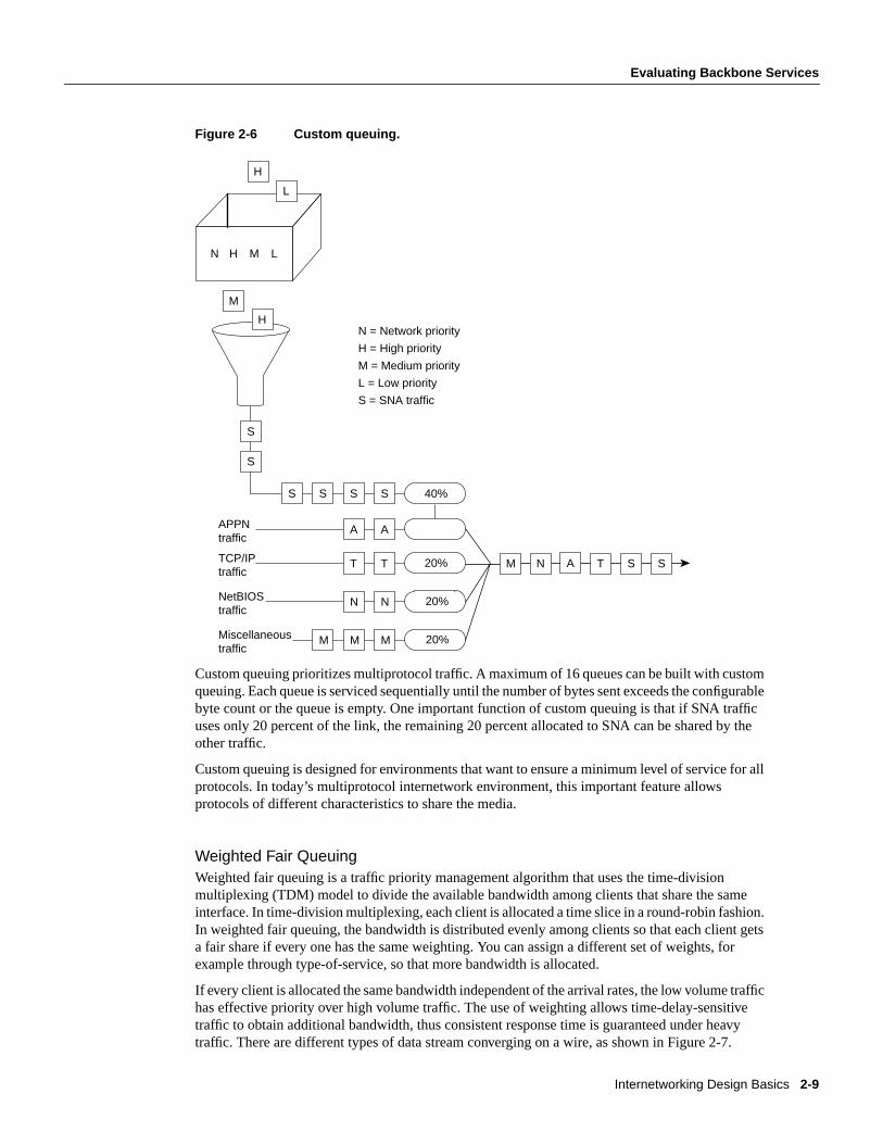
Translation between serial links running the SDLC protocol and Token Rings running LLC2 is alsoavailable. This is referred to as SDLLC frame translation. SDLLC frame translation allowsconnections between serial lines and Token Rings. This is useful for consolidating traditionallydisparate SNA/SDLC networks into a LAN-based, multiprotocol, multimedia backbone network.Using SDLLC, routers terminate SDLC sessions, translate SDLC frames to LLC2 frames, and thenforward the LLC2 frames using RSRB over a point-to-point or IP network. Because a router-basedIP network can use arbitrary media, such as FDDI, Frame Relay, X.25, or leased lines, routerssupport SDLLC over all such media through IP encapsulation.
A complex SDLLC configuration is shown in Figure 2-16.
Source-routebridged domain
Frames lose their RIFs in this direction
Frames gain RIFs in this direction
TokenRing
Transparentbridging domain
Transparentbridging ring
Source-route translational bridging
Router
Internetworking Design Basics 2-21
Identifying and Selecting Internetworking Capabilities
Figure 2-16 Complex SDLLC configuration.
Evaluating Local-Access ServicesThe following discussion addresses internetworking features that support local-access services.Local-access service topics outlined here include the following:
• Value-Added Network Addressing
• Network Segmentation
• Broadcast and Multicast Capabilities
• Naming, Proxy, and Local Cache Capabilities
• Media Access Security
• Router Discovery
Value-Added Network AddressingAddress schemes for LAN-based networks, such as NetWare and others, do not always adaptperfectly to use over multisegment LANs or WANs. One tool routers implement to ensure operationof such protocols is protocol-specifichelper addressing. Helper addressing is a mechanism to assistthe movement of specific traffic through a network when that traffic might not otherwise transit thenetwork.
3270 3270
RSRB Virtual Ring 100
C2
SDLLC Ring 8
Token Ring 10
SDLLC Ring 9
SDLLC Ring 7
32703x74
3x74
3x743270
C3
C1
WAN
37x5
Host
T0E0
Router A Router BSDLLC
S1
E0
S0
Router CSDLLC
E0
S0
Internetwork Design Guide2-22

Evaluating Local-Access Services
The use ofhelper addressingis best illustrated with an example. Consider the use of helper addressesin Novell IPX internetworks. Novell clients send broadcast messages when looking for a server. Ifthe server is not local, broadcast traffic must be sent through routers. Helper addresses and accesslists can be used together to allow broadcasts from certain nodes on one network to be directedspecifically to certain servers on another network. Multiple helper addresses on each interface aresupported, so broadcast packets can be forwarded to multiple hosts. Figure 2-17 illustrates the useof NetWare-based helper addressing.
Figure 2-17 Sample network map illustrating helper address broadcast control.
NetWare clients on Network AA are allowed to broadcast to any server on Network BB. Anapplicable access list would specify that broadcasts of type 10 will be permitted from all nodes onNetwork AA. A configuration-specified helper address identifies the addresses on Network BB towhich these broadcasts are directed. No other nodes on Network BB receive the broadcasts. No otherbroadcasts other than type 10 broadcasts are routed.
Any downstream networks beyond Network AA (for example, some Network AA1) are not allowedto broadcast to Network BB through Router C1, unless the routers partitioning Networks AA andAA1 are configured to forward broadcasts with a series of configuration entries. These entries mustbe applied to the input interfaces and be set to forward broadcasts between directly connectednetworks. In this way, traffic is passed along in a directed manner from network to network.
Network SegmentationThe splitting of networks into more manageable pieces is an essential role played by local-accessrouters. In particular, local-access routers implement local policies and limit unnecessary traffic.Examples of capabilities that allow network designers to use local-access routers to segmentnetworks include IP subnets, DECnet area addressing, and AppleTalk zones.
You can use local-access routers to implement local policies by placing the routers in strategiclocations and by configuring specific segmenting policies. For example, you can set up a series ofLAN segments with different subnet addresses; routers would be configured with suitable interfaceaddresses and subnet masks. In general, traffic on a given segment is limited to local broadcasts,
NetWareclient B
NetWare client A
NetWare server A
NetWareserver B
00b4.23cd.110a
0090.aa23.ef01
BB
AA
CC
Allows type 10 broadcasts only
Router C1 E1
E0
E2
Internetworking Design Basics 2-23

Identifying and Selecting Internetworking Capabilities
traffic intended for a specific end station on that segment, or traffic intended for another specificrouter. By distributing hosts and clients carefully, you can use this simple method of dividing up anetwork to reduce overall network congestion.
Broadcast and Multicast CapabilitiesMany protocols usebroadcastandmulticastcapabilities. Broadcasts are messages that are sent outto all network destinations. Multicasts are messages sent to a specific subset of network destinations.Routers inherently reduce broadcast proliferation by default. However, routers can be configured torelay broadcast traffic if necessary. Under certain circumstances, passing along broadcastinformation is desirable and possibly necessary. The key is controlling broadcasts and multicastsusing routers.
In the IP world, as with many other technologies, broadcast requests are very common. Unlessbroadcasts are controlled, network bandwidth can be seriously reduced. Routers offer variousbroadcast-limiting functions that reduce network traffic and minimize broadcast storms. Forexample, directed broadcasting allows for broadcasts to a specific network or a series of networks,rather than to the entire internetwork. When flooded broadcasts (broadcasts sent through the entireinternetwork) are necessary, Cisco routers support a technique by which these broadcasts are sentover a spanning tree of the network. The spanning tree ensures complete coverage without excessivetraffic because only one packet is sent over each network segment.
As discussed previously in the section “Value-Added Network Addressing,” broadcast assistance isaccommodated with thehelper address mechanisms. You can allow a router or series of routers torelay broadcasts that would otherwise be blocked by using helper addresses. For example, you canpermit retransmission of SAP broadcasts using helper addresses, thereby notifying clients ondifferent network segments of certain NetWare services available from specific remote servers.
The Cisco IP multicast feature allows IP traffic to be propagated from one source to any number ofdestinations. Rather than sending one packet to each destination, one packet is sent to a multicastgroup identified by a single IP destination group address. IP multicast provides excellent support forsuch applications as video and audio conferencing, resource discovery, and stock market trafficdistribution.
For full support of IP multicast, IP hosts must run the Internet Group Management Protocol (IGMP).IGMP is used by IP hosts to report their multicast group memberships to an immediatelyneighboring multicast router. The membership of a multicast group is dynamic. Multicast routerssend IGMP query messages on their attached local networks. Host members of a multicast grouprespond to a query by sending IGMP reports for multicast groups to which they belong. Reports sentby the first host in a multicast group suppress the sending of identical reports from other hosts of thesame group.
The multicast router attached to the local network takes responsibility for forwarding multicastdatagrams from one multicast group to all other networks that have members in the group. Routersbuild multicast group distribution trees (routing tables) so that multicast packets have loop-free pathsto all multicast group members so that multicast packets are not duplicated. If no reports are receivedfrom a multicast group after a set number of IGMP queries, the multicast routers assume the grouphas no local members and stop forwarding multicasts intended for that group.
Cisco routers also support Protocol Independent Multicast (PIM). For more information on thistopic, see Chapter 13, “Designing Internetworks for Multimedia.”
Naming, Proxy, and Local Cache CapabilitiesThree key router capabilities help reduce network traffic and promote efficient internetworkingoperation: name service support, proxy services, and local caching of network information.
Internetwork Design Guide2-24

Evaluating Local-Access Services
Network applications and connection services provided over segmented internetworks require arational way to resolve names to addresses. Various facilities accommodate this requirement. Anyrouter you select must support the name services implemented for different end-systemenvironments. Examples of supported name services include NetBIOS, IP’s Domain Name System(DNS) and IEN-116, and AppleTalk Name Binding Protocol (NBP).
A router can also act as aproxyfor a name server. The router’s support of NetBIOS name caching isone example of this kind of capability. NetBIOS name caching allows the router to maintain a cacheof NetBIOS names, which avoids the overhead of transmitting all of the broadcasts between clientand server NetBIOS PCs (IBM PCs or PS/2s) in an SRB environment. When NetBIOS name cachingis enabled, the router does the following:
• Notices when any host sends a series of duplicate query frames and limits retransmission to oneframe per period. The time period is a configuration parameter.
• Keeps a cache of mappings between NetBIOS server and client names and their MAC addresses.As a result, broadcast requests sent by clients to find servers (and by servers in response to theirclients) can be sent directly to their destinations, rather than being broadcast across the entirebridged network.
When NetBIOS name caching is enabled and default parameters are set on the router, the NetBIOSname server, and the NetBIOS name client, approximately 20 broadcast packets per login are kepton the local ring where they are generated.
In most cases, the NetBIOS name cache is best used when large amounts of NetBIOS broadcasttraffic might create bottlenecks on a WAN that connects local internetworks to distant locations.
The router can also save bandwidth (or handle nonconforming name resolution protocols) by usinga variety of other proxy facilities. By using routers to act on behalf of other devices to performvarious functions, you can more easily scale networks. Instead of being forced to add bandwidthwhen a new workgroup is added to a location, you can use a router to manage address resolution andcontrol message services. Examples of this kind of capability include the proxy explorer feature ofSRB and the proxy polling feature of STUN implementations.
Sometimes portions of networks cannot participate in routing activity or do not implement softwarethat conforms to generally implemented address-resolution protocols. Proxy implementations onrouters allow network designers to support these networks or hosts without reconfiguring aninternetwork. Examples of these kinds of capabilities include proxy ARP address resolution for IPinternetworks and NBP proxy in AppleTalk internetworks.
Local caches store previously learned information about the network so that new informationrequests do not need to be issued each time the same piece of information is desired. A router’s ARPcache stores physical address and network address mappings so that it does not need to broadcastARP requests more than once within a given time period for the same address. Address caches aremaintained for many other protocols as well, including DECnet, Novell IPX, and SRB, where RIFinformation is cached.
Media Access SecurityIf all corporate information is readily available to all employees, security violations andinappropriate file access can occur. To prevent this, routers must do the following:
• Keep local traffic from inappropriately reaching the backbone
• Keep backbone traffic from exiting the backbone into an inappropriate department or workgroupnetwork
Internetworking Design Basics 2-25

Identifying and Selecting Internetworking Capabilities
These two functions require packet filtering. Packet filtering capabilities should be tailored tosupport a variety of corporate policies. Packet filtering methods can reduce traffic levels on anetwork, thereby allowing a company to continue using its current technology rather than investingin more network hardware. In addition, packet filters can improve security by keeping unauthorizedusers from accessing information and can minimize network problems caused by excessivecongestion.
Routers support many filtering schemes designed to provide control over network traffic that reachesthe backbone. Perhaps the most powerful of these filtering mechanisms is the access list. Each of thefollowing possible local-access services can be provided through access lists:
• You have an Ethernet-to-Internet routing network and you want any host on the Ethernet to beable to form TCP connections to any host on the Internet. However, you do not want Internethosts to be able to form TCP connections into the Ethernet except to the SMTP port of a dedicatedmail host.
• You want to advertise only one network through a RIP routing process.
• You want to prevent packets that originated on any Sun workstation from being bridged on aparticular Ethernet segment.
• You want to keep a particular protocol based on Novell IPX from establishing a connectionbetween a source network or source port combination and a destination network or destinationport combination.
Access lists logically prevent certain packets from traversing a particular router interface, therebyproviding a general tool for implementing network security. In addition to this method, severalspecific security systems already exist to help increase network security. For example, the U.S.government has specified the use of an optional field within the IP packet header to implement ahierarchical packet security system called the Internet Protocol Security Option (IPSO).
IPSO support on routers addresses both the basic and extended security options described in a draftof the IPSO circulated by the Defense Communications Agency. This draft document is an earlyversion of Request for Comments (RFC) 1108. IPSO defines security levels (for example, TOPSECRET, SECRET, and others) on a per-interface basis and accepts or rejects messages based onwhether they include adequate authorization.
Some security systems are designed to keep remote users from accessing the network unless theyhave adequate authorization. For example, the Terminal Access Controller Access Control System(TACACS) is a means of protecting modem access into a network. The Defense Data Network(DDN) developed TACACS to control access to its TAC terminal servers.
The router’s TACACS support is patterned after the DDN application. When a user attempts to startan EXEC command interpreter on a password-protected line, TACACS prompts for a password. Ifthe user fails to enter the correct password, access is denied. Router administrators can controlvarious TACACS parameters, such as the number of retries allowed, the timeout interval, and theenabling of TACACS accounting.
The Challenge Handshake Authentication Protocol (CHAP) is another way to keep unauthorizedremote users from accessing a network. It is also commonly used to control router-to-routercommunications. When CHAP is enabled, a remote device (for example, a PC, workstation, router,or communication server) attempting to connect to a local router is “challenged” to provide anappropriate response. If the correct response is not provided, network access is denied.
CHAP is becoming popular because it does not require a secret password to be sent over the network.CHAP is supported on all router serial lines using Point-to-Point Protocol (PPP) encapsulation.
Internetwork Design Guide2-26

Choosing Internetworking Reliability Options
Router DiscoveryHosts must be able to locate routers when they need access to devices external to the local network.When more than one router is attached to a host’s local segment, the host must be able to locate therouter that represents the optimal path to the destination. This process of finding routers is calledrouter discovery.
The following are router discovery protocols:
• End System-to-Intermediate System (ES-IS)—This protocol is defined by the ISO OSI protocolsuite. It is dedicated to the exchange of information between intermediate systems (routers) andend systems (hosts). ESs send “ES hello” messages to all ISs on the local subnetwork. In turn,“IS hello” messages are sent from all ISs to all ESs on the local subnetwork. Both types ofmessages convey the subnetwork and network-layer addresses of the systems that generate them.Using this protocol, end systems and intermediate systems can locate one another.
• ICMP Router Discovery Protocol (IRDP)—Although the issue is currently under study, there iscurrently no single standardized manner for end stations to locate routers in the IP world. In manycases, stations are simply configured manually with the address of a local router. However,RFC 1256 outlines a router discovery protocol using the Internet Control Message Protocol(ICMP). This protocol is commonly referred to as IRDP.
• Proxy Address Resolution Protocol (ARP)—ARP uses broadcast messages to determine theMAC-layer address that corresponds to a particular internetwork address. ARP is sufficientlygeneric to allow use of IP with virtually any type of underlying media-access mechanism. Arouter that has proxy ARP enabled responds to ARP requests for those hosts for which it has aroute, which allows hosts to assume that all other hosts are actually on their network.
• RIP—RIP is a routing protocol that is commonly available on IP hosts. Many hosts use RIP tofind the address of the routers on a LAN or, when there are multiple routers, to pick the best routerto use for a given internetwork address.
Cisco routers support all the router discovery protocols listed. You can choose the router discoverymechanism that works best in your particular environment.
Choosing Internetworking Reliability OptionsOne of the first concerns of most network designers is to determine the required level of applicationavailability. In general, this key consideration is balanced against implementation cost. For mostorganizations, the cost of making a network completely fault tolerant is prohibitive. Determining theappropriate level of fault tolerance to be included in a network and where redundancy should be usedis not trivial.
The nonredundant internetwork design in Figure 2-18 illustrates the considerations involved withincreasing levels of internetwork fault tolerance.
Internetworking Design Basics 2-27

Identifying and Selecting Internetworking Capabilities
Figure 2-18 Typical nonredundant internetwork design.
The internetwork shown in Figure 2-18 has two levels of hierarchy: a corporate office and remoteoffices. Assume the corporate office has eight Ethernet segments, to which approximately 400 users(an average of 50 per segment) are connected. Each Ethernet segment is connected to a router. In theremote offices, two Ethernet segments are connected to the corporate office through a router. Therouter in each remote office is connected to the router in the corporate office through a T1 link.
The following sections address various approaches to creating redundant internetworks, providesome context for each approach, and contrast their relative merits and drawbacks. The following foursections are provided:
• Redundant Links Versus Meshed Topologies
• Redundant Power Systems
• Fault-Tolerant Media Implementations
• Backup Hardware
Redundant Links Versus Meshed TopologiesTypically, WAN links are the least reliable components in an internetwork, usually because ofproblems in the local loop. In addition to being relatively unreliable, these links are often an orderof magnitude slower than the LANs they connect. However, because they are capable of connectinggeographically diverse sites, WAN links often make up the backbone network, and are thereforecritical to corporate operations. The combination of potentially suspect reliability, lack of speed, andhigh importance makes the WAN link a good candidate for redundancy.
As a first step in making the example internetwork more fault tolerant, you might add a WAN linkbetween each remote office and the corporate office. This results in the topology shown in Figure2-19. The new topology has several advantages. First, it provides a backup link that can be used if aprimary link connecting any remote office and the corporate office fails. Second, if the routerssupport load balancing, link bandwidth has now been increased, lowering response times for usersand increasing application availability.
Corporate office
Remote office 1 Remote office 2 Remote office 3
Router
Router Router Router
Internetwork Design Guide2-28

Choosing Internetworking Reliability Options
Figure 2-19 Internetwork with dual links to remote offices.
Load balancing in transparent bridging and IGRP environments is another tool for increasing faulttolerance. Routers also support load balancing on either a per-packet or a per-destination basis in allIP environments. Per-packet load balancing is recommended if the WAN links are relatively slow(for example, less than 56 Kbps). If WAN links are faster than 56 Kbps, enabling fastswitching onthe routers is recommended. When fast switching is enabled, load balancing occurs on a per-destination basis.
Routers can automatically compensate for failed WAN links through routing algorithms ofprotocols, such as IGRP, OSPF, and IS-IS. If one link fails, the routing software recalculates therouting algorithm and begins sending all traffic through another link. This allows applications toproceed in the face of WAN link failure, improving application availability.
The primary disadvantage of duplicating WAN links to each remote office is cost. In the exampleoutlined in Figure 2-19, three new WAN links are required. In large star networks with more remoteoffices, 10 or 20 new WAN links might be needed, as well as new equipment (including new WANrouter interfaces). A lower cost alternative that is becoming increasingly popular links the remoteoffices using a meshed topology, as shown in Figure 2-20.
Figure 2-20 Evolution from a star to a meshed topology.
Corporate office
Remote office 1 Remote office 2 Remote office 3
Router
Router Router Router
Corporate office
Remote office 1 Remote office 2
A B
Before
Corporate office
Remote office 1 Remote office 2
A B
After
C
Internetworking Design Basics 2-29
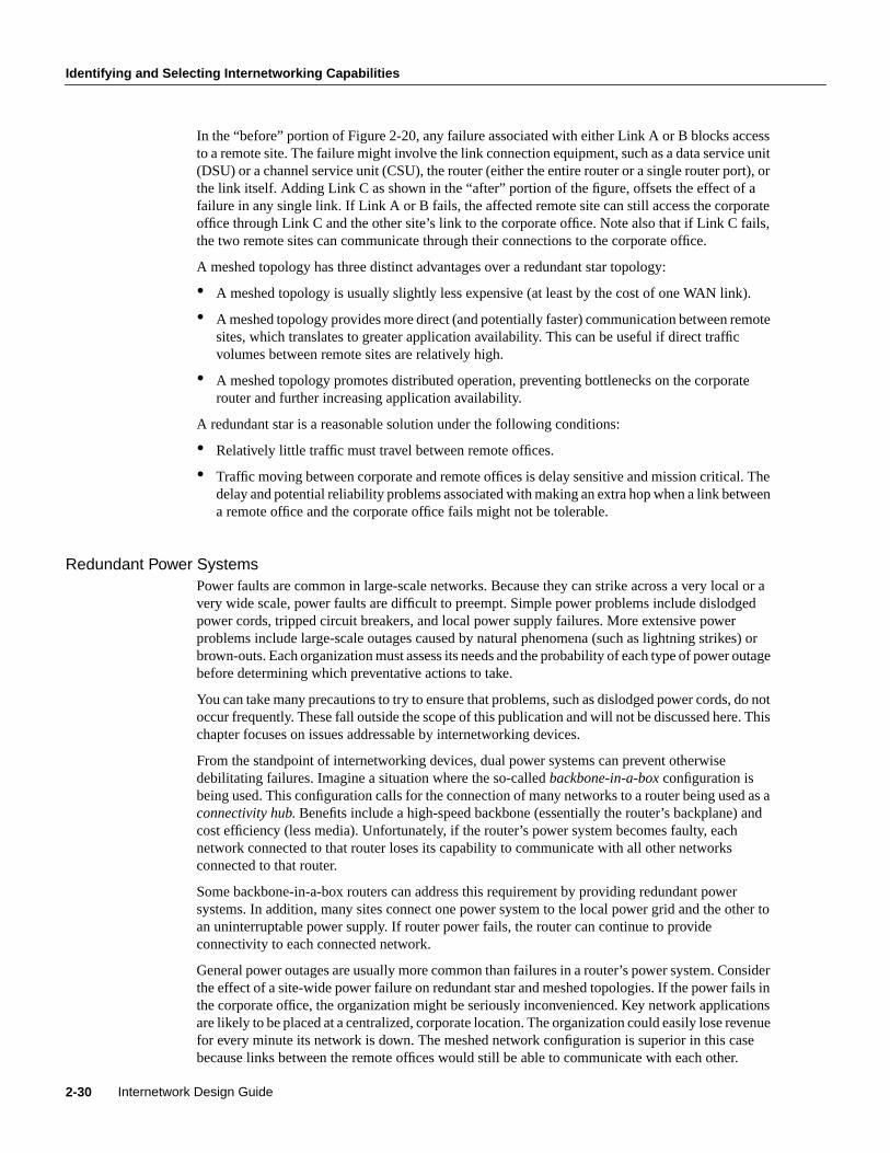
Identifying and Selecting Internetworking Capabilities
In the “before” portion of Figure 2-20, any failure associated with either Link A or B blocks accessto a remote site. The failure might involve the link connection equipment, such as a data service unit(DSU) or a channel service unit (CSU), the router (either the entire router or a single router port), orthe link itself. Adding Link C as shown in the “after” portion of the figure, offsets the effect of afailure in any single link. If Link A or B fails, the affected remote site can still access the corporateoffice through Link C and the other site’s link to the corporate office. Note also that if Link C fails,the two remote sites can communicate through their connections to the corporate office.
A meshed topology has three distinct advantages over a redundant star topology:
• A meshed topology is usually slightly less expensive (at least by the cost of one WAN link).
• A meshed topology provides more direct (and potentially faster) communication between remotesites, which translates to greater application availability. This can be useful if direct trafficvolumes between remote sites are relatively high.
• A meshed topology promotes distributed operation, preventing bottlenecks on the corporaterouter and further increasing application availability.
A redundant star is a reasonable solution under the following conditions:
• Relatively little traffic must travel between remote offices.
• Traffic moving between corporate and remote offices is delay sensitive and mission critical. Thedelay and potential reliability problems associated with making an extra hop when a link betweena remote office and the corporate office fails might not be tolerable.
Redundant Power SystemsPower faults are common in large-scale networks. Because they can strike across a very local or avery wide scale, power faults are difficult to preempt. Simple power problems include dislodgedpower cords, tripped circuit breakers, and local power supply failures. More extensive powerproblems include large-scale outages caused by natural phenomena (such as lightning strikes) orbrown-outs. Each organization must assess its needs and the probability of each type of power outagebefore determining which preventative actions to take.
You can take many precautions to try to ensure that problems, such as dislodged power cords, do notoccur frequently. These fall outside the scope of this publication and will not be discussed here. Thischapter focuses on issues addressable by internetworking devices.
From the standpoint of internetworking devices, dual power systems can prevent otherwisedebilitating failures. Imagine a situation where the so-calledbackbone-in-a-box configuration isbeing used. This configuration calls for the connection of many networks to a router being used as aconnectivity hub. Benefits include a high-speed backbone (essentially the router’s backplane) andcost efficiency (less media). Unfortunately, if the router’s power system becomes faulty, eachnetwork connected to that router loses its capability to communicate with all other networksconnected to that router.
Some backbone-in-a-box routers can address this requirement by providing redundant powersystems. In addition, many sites connect one power system to the local power grid and the other toan uninterruptable power supply. If router power fails, the router can continue to provideconnectivity to each connected network.
General power outages are usually more common than failures in a router’s power system. Considerthe effect of a site-wide power failure on redundant star and meshed topologies. If the power fails inthe corporate office, the organization might be seriously inconvenienced. Key network applicationsare likely to be placed at a centralized, corporate location. The organization could easily lose revenuefor every minute its network is down. The meshed network configuration is superior in this casebecause links between the remote offices would still be able to communicate with each other.
Internetwork Design Guide2-30

Choosing Internetworking Reliability Options
If power fails at a remote site, all connections to that remote site will be terminated unless otherwiseprotected. Neither the redundant star nor the meshed topology is superior. In both cases, all otherremote offices will still be able to communicate with the corporate office. Generally, power failuresin a remote office are more serious when network services are widely distributed.
To protect against local and site-wide power outages, some companies have negotiated anarrangement with local power companies to use multiple power grids within their organization.Failure within one power grid will not affect the network if all critical components have access tomultiple power grids. Unfortunately, this arrangement is very expensive and should only beconsidered by companies with substantial resources, extremely mission-critical operations, and arelatively high likelihood of power failures.
The effect of highly localized power failures can be minimized with prudent network planning.Wherever possible, redundant components should use power supplied by different circuits. Further,these redundant components should not be physically colocated. For example, if redundant routersare employed for all stations on a given floor, these routers can be physically stationed in wiringclosets on different floors. This prevents local wiring closet power problems from affecting thecapability of all stations on a given floor to communicate. Figure 2-21 shows such a configuration.
Figure 2-21 Redundant components on different floors.
For some organizations, the need for fault tolerance is so great that potential power failures areprotected against with a duplicate corporate data center. Organizations with these requirements oftenlocate a redundant data center in another city, or in a part of the same city that is some distance fromthe primary data center. All backend services are duplicated, and transactions coming in from remoteoffices are sent to both data centers. This configuration requires duplicate WAN links from all remoteoffices, duplicate network hardware, duplicate servers and server resources, and leasing anotherbuilding. Because this approach is so costly, it is typically the last step taken by companies desiringthe ultimate in fault tolerance.
Partial duplication of the data center is also a possibility. Several key servers and links to thoseservers can be duplicated. This is a common compromise to the problem presented by power failures.
To end stations on floor X+2
End stations
End stations
Shared media LANs
Shared media LANs
Router on floor X-1
Floor X+1
Floor X
To other routers
To other routers
Router
Router
Router
Router
Internetworking Design Basics 2-31

Identifying and Selecting Internetworking Capabilities
Fault-Tolerant Media ImplementationsMedia failure is another possible network fault. Included in this category are all problems associatedwith the media and its link to each individual end station. Under this definition, media componentsinclude network interface controller failures, lobe or attachment unit interface (AUI) cable failures,transceiver failures, hub failures, and all failures associated with media components (for example,the cable itself, terminators, and other parts). Many media failures are caused by operator negligenceand cannot easily be eliminated.
One way to reduce the havoc caused by failed media is to divide existing media into smallersegments and support each segment with different hardware. This minimizes the effect of a failureon a particular segment. For example, if you have 100 stations attached to a single switch, movesome of them to other switches. This reduces the effect of a hub failure and of certain subnetworkfailures. If you place an internetworking device (such as a router) between segments, you protectagainst additional problems and cut subnetwork traffic.
As shown in Figure 2-21, redundancy can be employed to help minimize media failures. Each stationin this figure is attached to two different media segments. NICs, hub ports, and interface cables areall redundant. This approach doubles the cost of network connectivity for each end station as wellas the port usage on all internetworking devices, and is therefore only recommended in situationswhere complete redundancy is required. It also assumes that end station software, including both thenetwork and the application subsystems, can handle and effectively use the redundant components.The application software or the networking software or both must be able to detect network failuresand initiate use of the other network.
Certain media access protocols have some fault-tolerant features built in. Token Ring multistationaccess units (MAUs) can detect certain media connection failures and bypass the failure internally.FDDI dual rings can wrap traffic onto the backup ring to avoid portions of the network withproblems.
From a router’s standpoint, many media failures can be bypassed so long as alternative paths areavailable. Using various hardware detection techniques, routers can sense certain media-levelproblems. If routing updates or routing keepalive messages have not been received from devices thatwould normally be reached through a particular router port, the router will soon declare that routedown and will look for alternative routes. Meshed networks provide these alternative paths, allowingthe router to compensate for media failures.
Backup HardwareLike all complex devices, routers, switches, and other internetworking devices develop hardwareproblems. When serious failures occur, the use of dual devices can effectively reduce the adverseeffects of a hardware failure. After a failure, discovery protocols help end stations choose new pathswith which to communicate across the network. If each network connected to the failed device hasan alternative path out of the local area, complete connectivity will still be possible.
For example, when backup routers are used, routing metrics can be set to ensure that the backuprouters will not be used unless the primary routers are not functioning. Switchover is automatic andrapid. For example, consider the situation shown in Figure 2-22. In this network, dual routers areused at all sites with dual WAN links. If Router R1 fails, the routers on FDDI 1 will detect the failureby the absence of messages from Router R1. Using any of several dynamic routing protocols,Router A, Router B, and Router C will designate Router R3 as the new next hop on the way toremote resources accessible via Router R4.
Internetwork Design Guide2-32

Identifying and Selecting Internetworking Devices
Figure 2-22 Redundant FDDI router configuration.
Many networks are designed with multiple routers connecting particular LANs in order to provideredundancy. In the past, the effectiveness of this design was limited by the speed at which the hostson those LANs detected a topology update and changed routers. In particular, IP hosts tend to beconfigured with a default gateway or configured to use Proxy ARP in order to find a router on theirLAN. Convincing an IP host to change its router usually required manual intervention to clear theARP cache or to change the default gateway.
The Hot Standby Router Protocol (HSRP) is a solution that allows network topology changes to betransparent to the host. HSRP typically allows hosts to reroute in approximately 10 seconds. HSRPis supported on Ethernet, Token Ring, FDDI, Fast Ethernet, and ATM.
An HSRP group can be defined on each LAN. All members of the group know the standby IP addressand the standby MAC address. One member of the group is elected the leader. The lead routerservices all packets sent to the HSRP group address. The other routers monitor the leader and act asHSRP routers. If the lead router becomes unavailable, the HSRP router elects a new leader whoinherits the HSRP MAC address and IP address.
High-end routers (Cisco 4500, 7000, and 7500 families) can support multiple MAC addresses on thesame Ethernet or FDDI interface, allowing the routers to simultaneously handle both traffic that issent to the standby MAC address and the private MAC address. The commands for enabling HSRPand configuring an HSRP group arestandby ip andstandby group.
Identifying and Selecting Internetworking DevicesNetwork designers have four basic types of internetworking devices available to them:
• Hubs (concentrators)
• Bridges
• Switches
• Routers
FDDI 1
FDDI 2
Local site
Remote site
Router A
Router B
Router C
Router R1
Router R3
Router R2
Router R4
Router X
Router Y
Router Z
Internetworking Design Basics 2-33

Identifying and Selecting Internetworking Devices
For a summary of these four internetworking devices, see Table 2-1 earlier in this chapter. Datacommunications experts generally agree that network designers are moving away from bridges andprimarily using switches and routers to build internetworks. Consequently, this section focuses onthe role of switches and routers in designing internetworks.
Switches can be functionally divided into two main groups: Layer 2 switches and multilayerswitches that provide Layer 2 and Layer 3 switching capabilities. Today, network designers arereplacing hubs in their wiring closets with switches to increase their network performance andprotect their existing wiring investments.
Routers segment network traffic based on the destination network layer address (Layer 3) rather thanthe workstation data link layer or MAC address. Consequently, routers are protocol dependent.
Benefits of Switches (Layer 2 Services)An individual Layer 2 switch might offer some or all of the following benefits:
• Bandwidth—LAN switches provide excellent performance for individual users by allocatingdedicated bandwidth to each switch port. Each switch port represents a different networksegment. This technique is known asmicrosegmenting.
• VLANs—LAN switches can group individual ports into switched logical workgroups calledVLANs, thereby restricting the broadcast domain to designated VLAN member ports. VLANsare also known as switched domains and autonomous switching domains. Communicationbetween VLANs requires a router.
• Automated packet recognition and translation—This capability allows the switch to translateframe formats automatically, such as Ethernet MAC to FDDI SNAP.
Benefits of Routers (Layer 3 Services)Because routers use Layer 3 addresses, which typically have structure, routers can use techniques(such as address summarization) to build networks that maintain performance and responsiveness asthey grow in size. By imposing structure (usually hierarchical) on a network, routers can effectivelyuse redundant paths and determine optimal routes even in a dynamically changing network.
Routers are necessary to ensure scalability as the network grows and expands. They provide thefollowing capabilities that are vital in network designs:
• Broadcast and multicast control
• Broadcast segmentation
• Security
• Quality of service (QoS)
• Multimedia
Backbone Routing OptionsIn an ideal world, the perfect enterprise-wide internetwork would feature a single, bullet-proofnetwork protocol capable of transporting all manner of data communications seamlessly, error free,and with sufficient resilience to accommodate any unforeseen connectivity disruption. However, inthe real world, there are many protocols with varying levels of resilience.
In designing a backbone for your organization, you might consider several options. These optionsare typically split into the following two primary categories:
Internetwork Design Guide2-34

Types of Switches
• Multiprotocol routing backbone
• Single-protocol backbone
The following discussions outline the characteristics and properties of these two strategies.
Multiprotocol Routing BackboneWhen multiple network layer protocols are routed throughout a common backbone withoutencapsulation (also referred to asnative mode routing), the environment is referred to as amultiprotocol routing backbone. A multiprotocol backbone environment can adopt one of tworouting strategies, or both, depending on the routed protocol involved. The two strategies aregenerally referred to as the following:
• Integrated routing—Integrated routing involves the use of a single routing protocol (for example,a link state protocol) that determines the least cost path for different routed protocols.
• Ships in the night—The ships-in-the-night approach involves the use of a different routingprotocol for each network protocol. For instance, some large-scale networks might featuremultiple protocols in which Novell IPX traffic is routed using a proprietary version of the RoutingInformation Protocol (RIP), IP is routed with IGRP, and DECnet Phase V traffic is routed via ISOCLNS-compliant IS-IS.
Each of these network layer protocols is routed independently, with separate routing processeshandling their traffic and separate paths calculated. Mixing routers within an internetwork thatsupports different combinations of multiple protocols can create a confusing situation, particularlyfor integrated routing. In general, integrated routing is easier to manage if all the routers attached tothe integrated routing backbone support the same integrated routing scheme. Routes for otherprotocols can be calculated separately. As an alternative, you can use encapsulation to transmit trafficover routers that do not support a particular protocol.
Single-Protocol BackboneWith a single-protocol backbone, all routers are assumed to support a single routing protocol for asingle network protocol. In this kind of routing environment, all other routing protocols are ignored.If multiple protocols are to be passed over the internetwork, unsupported protocols must beencapsulated within the supported protocol or they will be ignored by the routing nodes.
Why implement a single-protocol backbone? If relatively few other protocols are supported at alimited number of isolated locations, it is reasonable to implement a single protocol backbone.However, encapsulation does add overhead to traffic on the network. If multiple protocols aresupported widely throughout a large internetwork, a multiprotocol backbone approach is likely towork better.
In general, you should support all the network layer protocols in an internetwork with a nativerouting solution and implement as few network layer protocols as possible.
Types of SwitchesSwitches can be categorized as follows:
• LAN switches—The switches within this category can be further divided into Layer 2 switchesand multilayer switches.
• ATM switches—ATM switching and ATM routers offer greater backbone bandwidth required byhigh-throughput data services.
Internetworking Design Basics 2-35

Identifying and Selecting Internetworking Devices
Network managers are adding LAN switches to their wiring closets to augment bandwidth andreduce congestion in existing shared-media hubs while using new backbone technologies, such asFast Ethernet and ATM.
LAN SwitchesToday’s cost-effective, high-performance LAN switches offer network managers the followingbenefits:
• Superior microsegmentation
• Increased aggregate data forwarding
• Increased bandwidth across the corporate backbone
LAN switches address end users’ bandwidth needs for wiring closet applications. By deployingswitches rather than traditional shared hubs, network designers can increase performance andleverage the current investments in existing LAN media and adapters. These switches also offerfunctionality not previously available, such as VLANs, that provide the flexibility to use software tomove, add, and change users across the network.
LAN switches are also suited to provide segment switching and scalable bandwidth within networkdata centers by delivering switched links to interconnect existing hubs in wiring closets, LANswitches, and server farms. Cisco provides the Catalyst family of multilayer switches for connectingmultiple wiring closet switches or shared hubs into a backbone configuration.
ATM SwitchesEven though all ATM switches perform cell relay, ATM switches differ markedly in the followingcapabilities:
• Variety of interfaces and services that are supported
• Redundancy
• Depth of ATM internetworking software
• Sophistication of traffic management mechanism
Just as there are routers and LAN switches available at various price/performance points withdifferent levels of functionality, ATM switches can be segmented into the following four distincttypes that reflect the needs of particular applications and markets:
• Workgroup ATM switches
• Campus ATM switches
• Enterprise ATM switches
• Multiservice access switches
Cisco offers a complete range of ATM switches.
Workgroup and Campus ATM SwitchesWorkgroup ATM switches have Ethernet switch ports and an ATM uplink to connect to a campusATM switch. An example of a workgroup ATM switch is the Cisco Catalyst 5000.
Campus ATM switchesare generally used for small-scale ATM backbones (for example, to link ATMrouters or LAN switches). This use of ATM switches can alleviate current backbone congestion andenable the deployment of such new services as VLANs. Campus switches need to support a wide
Internetwork Design Guide2-36

Switches and Routers Compared
variety of both local backbone and WAN types, but be price/performance optimized for the localbackbone function. In this class of switches, ATM routing capabilities that allow multiple switchesto be tied together is very important. Congestion control mechanisms for optimizing backboneperformance is also important. The LightStream 1010 family of ATM switches is an example of acampus ATM switch. For more information on deploying workgroup and campus ATM switches inyour internetwork, see Chapter 12, “Designing Switched LAN Internetworks.”
Enterprise ATM SwitchesEnterprise ATM switches are sophisticated multiservice devices that are designed to form the corebackbones of large, enterprise networks. They are intended to complement the role played by today’shigh-end multiprotocol routers. Enterprise ATM switches are used to interconnect campus ATMswitches. Enterprise-class switches, however, can act not only as ATM backbones but can serve asthe single point of integration for all of the disparate services and technology found in enterprisebackbones today. By integrating all of these services onto a common platform and a common ATMtransport infrastructure, network designers can gain greater manageability and eliminate the need formultiple overlay networks.
Cisco’s BPX/AXIS is a powerful broadband ATM switch designed to meet the demanding,high-traffic needs of a large private enterprise or public service provider. For more information ondeploying enterprise ATM switches in your internetwork, see Chapter 8, “Designing ATMInternetworks.”
Multiservice Access SwitchesBeyond private networks, ATM platforms will also be widely deployed by service providers both ascustomer premises equipment (CPE) and within public networks. Such equipment will be used tosupport multiple MAN and WAN services—for example, Frame Relay switching, LANinterconnect, or public ATM services—on a common ATM infrastructure. Enterprise ATM switcheswill often be used in these public network applications because of their emphasis on high availabilityand redundancy, their support of multiple interfaces, and capability to integrate voice and data.
Switches and Routers ComparedTo highlight the differences between switches and routers, the following sections examine thedifferent roles of these devices in the following situations:
• Implementation of VLANs
• Implementation of switched internetworks
Role of Switches and Routers in VLANsVLANs address the following two problems:
• Scalability issues of a flat network topology
• Simplification of network management by facilitating network reconfigurations (moves andchanges)
A VLAN consists of a single broadcast domain and solves the scalability problems of large flatnetworks by breaking a single broadcast domain into several smaller broadcast domains or VLANs.Virtual LANs offer easier moves and changes in a network design than traditional networks. LANswitches can be used to segment networks into logically defined virtual workgroups. This logicalsegmentation, commonly referred to as VLAN communication, offers a fundamental change in how
Internetworking Design Basics 2-37

Identifying and Selecting Internetworking Devices
LANs are designed, administered, and managed. Although logical segmentation provides substantialbenefits in LAN administration, security, and management of network broadcast across theenterprise, there are many components of VLAN solutions that network designers should considerprior to large scale VLAN deployment.
Switches and routers each play an important role in VLAN design. Switches are the core devicethat controls individual VLANs while routers provide interVLAN communication, as shown inFigure 2-23.
Figure 2-23 Role of switches and routers in VLANs.
Switches remove the physical constraints imposed by a shared-hub architecture because theylogically group users and ports across the enterprise. As a replacement for shared hubs, switchesremove the physical barriers imposed within each wiring closet. Additionally, the role of the routerevolves beyond the more traditional role of firewalls and broadcast suppression to policy-basedcontrol, broadcast management, and route processing and distribution. Equally as important,routers remain vital for switched architectures configured as VLANs because they provide thecommunication between VLANs. Routers also provide VLAN access to shared resources, such asservers and hosts. For more information on deploying VLANs, see Chapter 12, “Designing SwitchedLAN Internetworks.”
Examples of Campus Switched Internetwork DesignsA successful campus switched internetworking solution must combine the benefits of both routersand switches in every part of the network, as well as offer a flexible evolution path fromshared-media networking to switched internetworks.
For example, incorporating switches in campus network designs will generally result in thefollowing benefits:
• High bandwidth
• Improved performance
• Low cost
• Easy configuration
If you need advanced internetworking services, however, routers are necessary. Routers offer thefollowing services:
Floor 3
Access controlbetween VLANs
VLAN Group 1 VLAN Group 2
Floor 2
Floor 1
Internetwork Design Guide2-38

Switches and Routers Compared
• Broadcast firewalling
• Hierarchical addressing
• Communication between dissimilar LANs
• Fast convergence
• Policy routing
• QoS routing
• Security
• Redundancy and load balancing
• Traffic flow management
• Multimedia group membership
Some of these router services will be offered by switches in the future. For example, support formultimedia often requires a protocol, such as Internet Group Management Protocol (IGMP), thatallows workstations to join a group that receives multimedia multicast packets. In the future, Ciscowill allow switches to participate in this process by using the Cisco Group Management Protocol(CGMP). One router will still be necessary, but you will not need a router in each departmentbecause CGMP switches can communicate with the router to determine if any of their attached usersare part of a multicast group.
Switching and bridging sometimes can result in non-optimal routing of packets. This is becauseevery packet must go through the root bridge of the spanning tree. When routers are used, the routingof packets can be controlled and designed for optimal paths. Cisco now provides support forimproved routing and redundancy in switched environments by supporting one instance of thespanning tree per VLAN.
The following figures illustrate how network designers can use switches and routers to evolve theirshared-media networks to switching internetworks. Typically, this evolution to a campus switchedinternetwork architecture will extend over four phases.
Phase 1 is the microsegmentation phase in which network designers retain their hubs and routers,but insert a LAN switch to enhance performance. Figure 2-24 shows an example of how a LANswitch can be used to segment a network.
Figure 2-24 Using switches for microsegmentation.
Cisco router
Shared hubLAN switch
Internetworking Design Basics 2-39

Identifying and Selecting Internetworking Devices
Phase 2 is the addition of high-speed backbone technology and routing between switches. LANswitches perform switch processing and provide dedicated bandwidth to the desktop and toshared-media hubs. Backbone routers are attached to either Fast Ethernet or ATM switches. Theincrease in backbone bandwidth matches the increase bandwidth in the wiring closet. Figure 2-25shows an example of how you can add high-speed backbone technology and routing betweenexisting switches in your network.
Figure 2-25 Adding high-speed backbone technology and routing between switches.
In Phase 3, routers are distributed between the LAN switches in the wiring closet and the high-speedcore switch. The network backbone is now strictly a high-speed transport mechanism with all otherdevices, such as the distributed routers, at the periphery. Figure 2-26 illustrates such a network.
Figure 2-26 Distributing routers between high-speed core and LAN switches.
ATM campus switch
LAN switch
High-speedcore switch
Router
LAN switch
High-speedswitch
Internetwork Design Guide2-40

Summary
Phase 4 is the final phase—the end point. It involves end-to-end switching with integral VLANs andmultilayer switching capability. By this point, Layer 2 and Layer 3 integrated switching is distributedacross the network and is connected to the high-speed core. Figure 2-27 shows an example of thisfinal phase.
Figure 2-27 End-to-end switching with VLAN and multilayer switching capability.
SummaryNow that the basic internetworking devices and general design principles have been examined, theremaining chapters in this part focus on the different technologies available when designing aninternetwork.
RouterHigh-speedcore switch
LAN switch
Si
Si
Internetworking Design Basics 2-41

Summary
Internetwork Design Guide2-42