Embed Size (px)
Citation preview

INTERNATIONAL ORGANISATION FOR STANDARDISATION
ORGANISATION INTERNATIONALE DE NORMALISATION
ISO/IEC JTC1/SC29/WG11
CODING OF MOVING PICTURES AND AUDIO
ISO/IEC JTC1/SC29/WG11
MPEG2011/N12355
November 2011, Geneva, Switzerland
Source Video Subgroup
Status draft
Title Internet Video Coding Test Model (ITM) Version 1.0
Editor Siwei Ma, Yunfei Wang, Jianwen Chen
N12355
-ii-
Table of Contents
1 Introduction ................................................................................................................... 6 1.1 Objective................................................................................................................. 6 1.2 Technical Summary ................................................................................................ 6 1.3 Prediction Technique .............................................................................................. 6 1.3.1 Picture Partition ............................................................................................... 6 1.3.2 Transform and Quantization ............................................................................ 7 2 Terms and Definitions ................................................................................................... 8 2.1 Reserved ................................................................................................................. 8 2.2 Bit string ................................................................................................................. 8 2.3 Bitstream................................................................................................................. 8 2.4 Bitstream buffer ...................................................................................................... 8 2.5 Bitstream order ....................................................................................................... 8 2.6 Variable length coding ............................................................................................ 8 2.7 Transform coefficient ............................................................................................. 8 2.8 Encoding presentation ............................................................................................ 8 2.9 Encoding process .................................................................................................... 9 2.10 Encoder ................................................................................................................... 9 2.11 Coded picture .......................................................................................................... 9 2.12 Flag ......................................................................................................................... 9 2.13 Compensation ......................................................................................................... 9 2.14 Residual .................................................................................................................. 9 2.15 Reference index ...................................................................................................... 9 2.16 Reference picture .................................................................................................... 9 2.17 Layer ....................................................................................................................... 9 2.18 Profile ..................................................................................................................... 10 2.19 Non-reference picture ............................................................................................. 10 2.20 Component ............................................................................................................. 10 2.21 Inverse transform .................................................................................................... 10 2.22 Dequantization ........................................................................................................ 10 2.23 Block ...................................................................................................................... 10 2.24 Block scan .............................................................................................................. 10 2.25 Luma ....................................................................................................................... 10 2.26 Quantization parameter ........................................................................................... 10 2.27 Quantized coefficient .............................................................................................. 11 2.28 Raster scan .............................................................................................................. 11 2.29 Macroblock ............................................................................................................. 11 2.30 Macroblock address ................................................................................................ 11 2.31 Macroblock line ...................................................................................................... 11 2.32 Macroblock position ............................................................................................... 11 2.33 Backward prediction ............................................................................................... 11 2.34 Partitioning ............................................................................................................. 11 2.35 Level ....................................................................................................................... 12 2.36 AC coefficient ........................................................................................................ 12 2.37 Decode processing .................................................................................................. 12 2.38 Decoding process .................................................................................................... 12 2.39 Decoder................................................................................................................... 12 2.40 Decoding order ....................................................................................................... 12 2.41 Decoded picture ...................................................................................................... 12 2.42 Decoded picture buffer ........................................................................................... 12 2.43 Parse ....................................................................................................................... 12 2.44 Forbidden ................................................................................................................ 13 2.45 X-profile decoder .................................................................................................... 13

N12355
-iii-
2.46 Start code ................................................................................................................ 13 2.47 Forward prediction ................................................................................................. 13 2.48 Forward inter decoded picture ................................................................................ 13 2.49 Chroma ................................................................................................................... 13 2.50 Sequence ................................................................................................................. 13 2.51 Output reorder delay ............................................................................................... 13 2.52 Output processing ................................................................................................... 14 2.53 Output order ............................................................................................................ 14 2.54 Bidirectional prediction .......................................................................................... 14 2.55 Bidirectional inter decoded picture ......................................................................... 14 2.56 Random access ....................................................................................................... 14 2.57 Random access point .............................................................................................. 14 2.58 Stuffing bits ............................................................................................................ 14 2.59 Slice ........................................................................................................................ 14 2.60 Slice header ............................................................................................................ 14 2.61 Skipped macroblock ............................................................................................... 14 2.62 Picture reordering ................................................................................................... 15 2.63 Display order .......................................................................................................... 15 2.64 Sample .................................................................................................................... 15 2.65 Width height ratio ................................................................................................... 15 2.66 Sample value .......................................................................................................... 15 2.67 Run ......................................................................................................................... 15 2.68 Prediction ................................................................................................................ 15 2.69 Prediction process ................................................................................................... 15 2.70 Prediction value ...................................................................................................... 15 2.71 Syntax element ....................................................................................................... 16 2.72 Source ..................................................................................................................... 16 2.73 Motion vector ......................................................................................................... 16 2.74 DC coefficient ........................................................................................................ 16 2.75 Frame ...................................................................................................................... 16 2.76 Inter coding ............................................................................................................. 16 2.77 Inter prediction ....................................................................................................... 16 2.78 Intra coding ............................................................................................................. 16 2.79 Intra decoded picture .............................................................................................. 16 2.80 Intra prediction ....................................................................................................... 17 2.81 Byte ........................................................................................................................ 17 2.82 Byte alignment ........................................................................................................ 17 3 Abbreviations ................................................................................................................. 18 4 Conventions ................................................................................................................... 19 4.1 Arithmetic operators ............................................................................................... 19 4.2 Logical operators .................................................................................................... 19 4.3 Relational operators ................................................................................................ 19 4.4 Bitwise operators .................................................................................................... 20 4.5 Assignment ............................................................................................................. 20 4.6 Mathemetical functions .......................................................................................... 20 4.7 Description of bitsteam syntax parsing process and decoding process ................... 21 4.7.1 Method of describing bitstream syntax ............................................................ 21 4.7.2 Functions ......................................................................................................... 22 4.7.3 Descriptor ........................................................................................................ 24 4.7.4 Reserved, forbidden and marker bit................................................................. 24 5 Bitstream syntax and semantics ..................................................................................... 25 5.1 Structure of coded video data ................................................................................. 25 5.1.1 Video sequence ................................................................................................ 25 5.1.2 Sequence header .............................................................................................. 25 5.1.3 Picture .............................................................................................................. 26 5.1.4 Color format .................................................................................................... 26 5.1.5 Picture types .................................................................................................... 26 5.1.6 Order between pictures .................................................................................... 26 5.1.7 Reference picture ............................................................................................. 27
N12355
-iv-
5.1.8 Slice ................................................................................................................. 27 5.1.9 Macroblock ...................................................................................................... 28 5.1.10 8x8 block ......................................................................................................... 28 5.1.11 4x4 block ......................................................................................................... 28 5.2 Bitstream syntax ..................................................................................................... 29 5.2.1 Start codes ....................................................................................................... 29 5.2.2 Video sequence ................................................................................................ 29 5.2.3 Extension and user data ................................................................................... 30 5.2.4 Picture .............................................................................................................. 31 5.2.5 Slice ................................................................................................................. 32 5.2.6 Macroblock ...................................................................................................... 32 5.2.7 Block ............................................................................................................... 34 5.3 Video bitstream semantics ...................................................................................... 34 5.3.1 Video sequence ................................................................................................ 34 5.3.2 Sequence header .............................................................................................. 35 5.3.3 Extension data and user data ........................................................................... 37 5.3.4 Picture .............................................................................................................. 38 5.3.5 Slice ................................................................................................................. 38 5.3.6 Macroblock ...................................................................................................... 38 5.3.7 Block ............................................................................................................... 39 6 Video decoding process ................................................................................................. 41 6.1 High-level syntax structure ..................................................................................... 41 6.2 Variable length decoding ........................................................................................ 41 6.2.1 Initialization of the qcoder Decoder ................................................................ 42 6.2.2 Entropy decoding processing........................................................................... 43 6.2.3 Binary decoding method .................................................................................. 47 6.3 Inverse scanning ..................................................................................................... 57 6.3.1 Inverse scanning process for 4×4 block coefficients ....................................... 57 6.3.2 Inverse scanning process for 8×8 block coefficients ....................................... 57 6.4 Inverse quantization process ................................................................................... 58 6.5 Inverse transform process ....................................................................................... 59 6.5.1 Inverse transform for 4×4 block ...................................................................... 59 6.5.2 Inverse transform for 8×8 block ...................................................................... 60 6.6 Intra prediction ....................................................................................................... 62 6.6.1 Intra prediction modes of DC coefficients ....................................................... 63 6.6.2 Getting intra DC coefficients‟ prediction values ............................................. 63 6.6.3 Reconstruction ................................................................................................. 64 6.7 Inter prediction ....................................................................................................... 64 6.7.1 Inter prediction modes ..................................................................................... 65 6.7.2 Frame prediction modes selection ................................................................... 65 6.7.3 Motion vectors ................................................................................................. 66 6.7.4 Luma motion vectors prediction ...................................................................... 66 6.7.5 Forming predictors .......................................................................................... 67 6.7.6 Skipped mode macroblocks ............................................................................. 68 6.7.7 Combining predictions .................................................................................... 68 6.7.8 Adding prediction and coefficient data ............................................................ 69 7 Description of the Internet Video Coding Encoder........................................................ 70 7.1 General Coding Structure ....................................................................................... 70 7.2 Picture Partitioning ................................................................................................. 71 7.2.1 Macroblock ...................................................................................................... 71 7.2.2 Slice ................................................................................................................. 71 7.3 Intra Prediction ....................................................................................................... 71 7.4 Inter Prediction ....................................................................................................... 72 7.4.1 Motion vector prediction ................................................................................. 73 7.4.2 Skip Mode ....................................................................................................... 74 7.5 Transform ............................................................................................................... 74 7.5.1 1-D 4-point forward transform ........................................................................ 74 7.5.2 1-D 8-point forward transform ........................................................................ 74 7.6 Quantization ........................................................................................................... 75

N12355
-v-
7.7 Entropy Coding ...................................................................................................... 77 7.7.1 Binarization and Context model Selection (CS) .............................................. 77 7.7.2 Initialization..................................................................................................... 78 7.8 Encoder configurations ........................................................................................... 79 7.8.1 Constraint set 1 configuration.......................................................................... 79 7.8.2 Constraint set 2 configuration.......................................................................... 79 Annex A VLC coding table ........................................................................................................... 80 Annex B Profiles and levels ....................................................................................................................... 84 B.1 Profile 84 B.2 Level 84 B.3 Level constraints independent of profiles ............................................................................................ 85
N12355
-6-
1 Introduction
1.1 Objective
Internet Video Coding (IVC) is an effort to produce a video coding standard
whose baseline profile complies with the IVC CfP (N12204). This work has been
originated by the proposal made by a group of Chinese Universities (M22477).
This Core Experiment (CE) document includes descriptions of investigations of
coding modules in IVC, analysis of the coding performance of different
configurations to further improve the coding performance of the IVC tools included in
the test model (ITM1.0). Everybody is encouraged to propose further core
experiments. Changes to the test model must comply with the IVC CfP (N12204).
In Section 5 the decoder description, syntax and semantics are provided.
In Section 6 the encoder description is provided.
1.2 Technical Summary
The ITM includes a set of tools to achieve efficient video coding, including intra
prediction, inter prediction, transform, quantization and entropy coding, etc. Inter
prediction uses block-based motion vectors to eliminate redundancy between pictures;
intra prediction uses spatial prediction mode to eliminate redundancy within the
picture. The visual redundancy within the picture is eliminated by the transformation
and quantization of the prediction residual. And finally, motion vectors, prediction
modes, quantization parameters and transform coefficients are compressed using
entropy coding.
1.3 Prediction Technique
Intra prediction doesn‟t need to refer to other pictures, and the pictures coded by
intra prediction can serve as random access points of the encoded sequence.
Inter prediction needs to refer to previously decoded pictures, and decoding order
can be different from the source picture capture order at the encoder side or the
display order at the decoder side. The motion vector precision of Inter prediction can
be as precise as 1 / 4 pixel, and motion vectors are coded by predictive coding.
1.3.1 Picture Partition
The basic unit of video decoding in this part is macroblock. A macro block
consists of a 1616 luminance block and corresponding chroma blocks. Macroblock
can be further divided to 88 block and 4x4 block to perform the prediction.

N12355
-7-
1.3.2 Transform and Quantization
The unit of transform is 88 or 44 block. Transform coefficients are quantized
by scalar quantization.

N12355
-8-
2 Terms and Definitions
The terms and definitions below are applicable to the content in this part.
2.1 Reserved
Defines some special syntax element values which will be used to extend this
part in the future.
Note: These values should not exist in the bitstream which conforms to the
syntax defined in this part.
2.2 Bit string
Ordered string with limited number of bits. The left most bit is the most
significant bit (MSB), the right most bit is the least significant bit (LSB).
2.3 Bitstream
The binary bit stream generated by encoding the frame.
2.4 Bitstream buffer
The buffer which stores the bitstream.
2.5 Bitstream order
The order in the bitstream where the encoded frame located, which is the same as
the frame order in the decoding process.
2.6 Variable length coding
A reversible entropy coding process, which distributes short codewords to the
high-frequency symbols and distributes long codewords to the low-frequency
symbols.
2.7 Transform coefficient
A scalar in the transform domain.
2.8 Encoding presentation
The representation after the encoding process

N12355
-9-
2.9 Encoding process
The process which generates the bitstream conforms to the description in the
current part.
Note: This part doesn‟t specify the encoding process.
2.10 Encoder
The realization of the encoding process.
2.11 Coded picture
The representation of one picture after the encoding process.
2.12 Flag
A binary variable.
2.13 Compensation
Obtaining the addition of the decoded residual and the corresponding prediction
values.
2.14 Residual
The difference between the reconstructed samples and the corresponding
prediction values.
2.15 Reference index
The number of the reference frame or the corresponding field in the frame buff in
the decoding process.
2.16 Reference picture
Picture for inter prediction of subsequent pictures in the decoding process.
2.17 Layer
Layered structure in bitstream, of which higher layer includes lower layer. The
coding layers ranging from high to low are respectively: sequence, picture, slice,
macroblock and block.
N12355
-10-
2.18 Profile
A subset of syntax, semantics and algorithms defined in this part.
2.19 Non-reference picture
Picture not used for inter prediction of subsequent pictures in the decoding
process
2.20 Component
One of the three picture sample value matrices (one luma matrix and two chroma
matrices) or its single sample value.
2.21 Inverse transform
The process in which transform coefficient matrix is transformed into spatial
sample value matrix.
2.22 Dequantization
The process in which transform coefficients are obtained after scaling the
quantized coefficients.
2.23 Block
An MN sample value matrix or transform coefficient matrix (M columns and N
rows).
2.24 Block scan
Specified serial ordering of quantized coefficients.
2.25 Luma
Sample value matrix or single sample value representing the luma signal.
Note: the symbol representing luma is Y.
2.26 Quantization parameter
The parameter that dequantizes the quantized coefficients in the decoding
process.

N12355
-11-
2.27 Quantized coefficient
Transform coefficients before dequantization.
2.28 Raster scan
Maps a two dimensional rectangular raster into a one dimensional raster, in
which the entry of the one dimensional raster starts from the first row of the two
dimensional raster, and the scanning then goes through the second row and the third
row, and so on. Each raster row is scanned in the left to right order.
2.29 Macroblock
Includes a 1616 luma sample value block and its corresponding chroma sample
value blocks.
2.30 Macroblock address
Starting from the upper left macroblock and numbering according to the order of
raster scan, with an initial number 0.
2.31 Macroblock line
Consecutive macroblocks within the same vertical position that start from the left
coded picture boundary to the right. The height of one macroblock line is 16 samples.
2.32 Macroblock position
The two-dimensional coordinates of one macroblock in a picture denoted by
(x,y).The coordinate of the top left macroblock (x,y) is equal to (0,0); x is
incremented by 1 for each macroblock column from left to right; y is incremented by
1 for each macroblock row from top to bottom.
2.33 Backward prediction
Predict current picture by using future pictures in the display order as reference
pictures.
2.34 Partitioning
The process of dividing a set into subsets such that each element in the set
belong to only one of the subsets.
N12355
-12-
2.35 Level
A defined set of constraints on the values for the syntax elements and syntax
element parameters under certain level
2.36 AC coefficient
Any transform coefficient whose frequency indexes are non-zero in at least one
dimension.
2.37 Decode processing
Including the analyzing processing and the decoding processing.
2.38 Decoding process
The process that derives decoded pictures from syntax elements.
2.39 Decoder
One embodiment of the decoding process.
2.40 Decoding order
The order of decoding frames, which depends on the relationship of inter
prediction.
2.41 Decoded picture
The reconstructed picture out of the bitstream by the decoder.
2.42 Decoded picture buffer
The buffer used for saving the decoded pictures for prediction as well as output
reordering and output timing.
2.43 Parse
The procedure of getting the syntax element from the bitstream.

N12355
-13-
2.44 Forbidden
Define some special syntax elements, which should not exist in the bitstream
which conforms to the syntax defined in this part. The reason for forbidden is to avoid
the pseudo initial code in the bitstream.
2.45 X-profile decoder
The decoder which is able to decode the bitstream which satisfies the
specifications of a certain profile.
2.46 Start code
A 32-bit codeword which is unique in the whole bitstream. Start code has a lot of
usages, one of which is to identify the start point of the syntax structure in the
bitstream.
2.47 Forward prediction
The process of predicting the current picture by the past reference pictures in the
display order.
2.48 Forward inter decoded picture
Decoded pictures using only forward prediction in inter prediction.
2.49 Chroma
Sample value matrix or single sample value of one of the two colour difference
signals.
Notes: symbols of chroma are Cr and Cb.
2.50 Sequence
The highest level syntax structure of coding bitstream, including one or several
consecutive coded pictures.
2.51 Output reorder delay
The delay between the beginning of decoding one frame in the bitstream and the
output of the decoded picture, which is caused by the difference between the display
order and the decoding order.

N12355
-14-
2.52 Output processing
The process of deriving the output frame or field from the decoded picture.
2.53 Output order
The order of outputting decoded pictures, which is the same as the display order.
2.54 Bidirectional prediction
The process of predicting the current picture by the past reference pictures and
future reference pictures in the display order.
2.55 Bidirectional inter decoded picture
Decoded pictures using bidirectional prediction in inter prediction.
2.56 Random access
The ability to decode the bit-stream and restore the decoded picture from a point
which is not the starting point.
2.57 Random access point
The point which can be accessed randomly in the bit-stream.
2.58 Stuffing bits
The bit string which is inserted into bit-stream during encoding process and
should be aborted during the decoding process.
2.59 Slice
Several consecutive macroblock rows in the raster scan order.
2.60 Slice header
One part of the encoded slice which is the encoding presentation for the public
data of macroblocks in the slice.
2.61 Skipped macroblock
Macroblock without other encoding data except for the indicator “skipped”.

N12355
-15-
2.62 Picture reordering
The process of reordering the decoded pictures if the decoding order is different
from the output order.
2.63 Display order
The order of displaying decoded pictures.
2.64 Sample
The basic elements that compose the picture.
2.65 Width height ratio
The ratio of the horizontal distance between columns to the vertical distance
between rows of the luma samples in one frame.
Shown as , where is the horizontal width and is the vertical height.
2.66 Sample value
The amplitude value of a sample.
2.67 Run
A number of data elements of the same value in the decoding process. On one
hand, it means the number of zero coefficients before a non-zero coefficient in the
block scan; on the other hand, it means the number of skipped macroblocks.
2.68 Prediction
The implementation of the prediction process.
2.69 Prediction process
The process of estimating the decoded sample value or data element using a
predictor.
2.70 Prediction value
The value, which is the combination of the previously decoded sample values or
data elements, used in the decoding process of the next sample value/data element.

N12355
-16-
2.71 Syntax element
The analysis result of the data unit in the bitstream.
2.72 Source
The term describing the raw video clips or some of their attributes before the
encoding process.
2.73 Motion vector
A two-dimensional vector used for inter prediction which refers the current
picture to the reference picture, the value of which provides the coordinate offsets
between the current picture and the reference picture.
2.74 DC coefficient
A transform coefficient whose frequency indexes are zero in both dimensions
2.75 Frame
The representation of video signals in the space domain, Composed of one luma
sample matrix (Y) and two chroma sample matrices (Cb and Cr).
2.76 Inter coding
Coding one macroblock or picture using inter prediction.
2.77 Inter prediction
The process of deriving the prediction value for the current picture (or field)
using previously decoded pictures (or fields).
2.78 Intra coding
Coding one macroblock or picture using intra prediction.
2.79 Intra decoded picture
The decoded picture using only intra prediction. If the I frame uses field coding,
the first field can only use intra prediction.

N12355
-17-
2.80 Intra prediction
The process of deriving the prediction value for the current sample using
previously decoded sample values in the same decoded picture (or field).
2.81 Byte
8-bit bit string.
2.82 Byte alignment
Starting from the first bit in the bitstream, one bit is byte aligned if the position
of the bit is an integer multiple of eight.

N12355
-18-
3 Abbreviations
BBV: Bitstream Buffer Verifier
CBR: Constant Bit Rate
LSB: Least Significant Bit
MB: Macroblock
MSB: Most Significant Bit
VBR: Variable Bit Rate
VLC: Variable Length Coding

N12355
-19-
4 Conventions
The mathematical operators and their precedence rules used to describe this
Specification are similar to those used in the C programming language. However,
operators of integer divisions with truncation and of rounding are specifically defined.
If not specifically explained, numbering and counting begin from zero.
4.1 Arithmetic operators
Addition
– Subtraction (as a binary operator) or negation (as a unary prefix operator)
× Multiplication
ab Exponential operation. a is raised to power of b. also it can represent
superscript.
/ Integer division with truncation of the result toward zero. For example, 7/4
and –7/–4 are truncated to 1 and –7/4 and 7/–4 are truncated to –1.
Division in mathematical equations where no truncation or rounding is
intended
b
a Division in mathematical equations where no truncation or rounding is
intended
b
ai
if )( The summation of the f (i) with i taking integral values from a up to, b
(including b)
a % b Remainder from division of a by b. both a and b are positive integers
4.2 Logical operators
a && b Logical AND operation between a and b
a || b Logical OR operation between a and b
! Logical NOT operation
4.3 Relational operators
Greater than
Greater than or equal to
Less than
Less than or equal to
Equal to
! Not equal to

N12355
-20-
4.4 Bitwise operators
& AND operation
| OR operation
~ Negation operation
a >> b Shift a in 2‟s complement binary integer representation format to the right by
b bit positions. This operator is only defined with b, a positive integer
a << b Shift a in 2‟s complement binary integer representation format to the left by b
bit positions. This operator is only defined with b, a positive integer
4.5 Assignment
Assignment operator
Increment, x++ is equivalent to x = x + 1. When this operator is used for an
array index, the variable value is obtained before the auto increment operation
-- Decrement, i.e. x– – is equivalent to x = x - 1. When this operator is used for
an array index the variable value is obtained before the auto decrement operation
+= Addition assignment operator, for example x += 3 corresponds to
x = x + 3, x += (-3) is equivalent to x = x + (-3)
-= Subtraction assignment operator,for example x -= 3 corresponds to
x = x - 3, x -= (-3) is equivalent to x = x - (-3)
4.6 Mathemetical functions
Abs(x) =; 0
; 0
x x
x x
(1)
Ceil(x) takes the smallest integer not smaller than x (2)
Clip1(x) = Clip3(0, 255, x) (3)
Clip3(a,b,c) =
;
;
; else
a c a
b c b
c
(4)
Floor(x) takes the biggest integer not bigger than x (5)
Log2(x) logarithm number of x with base 2
Log10(x) logarithm number of x with base 10 (6)
Median(x,y,z) = x + y + z – Min(x, Min(y, z)) – Max(x, Max(y, z)) (7)
Min(x, y) = ;
;
x x y
y x y
(8)

N12355
-21-
Max(x, y) = ;
;
x x y
y x y
(9)
Round(x) = Sign(x) Floor(Abs(x) + 0.5)
Sign(x) =
01
01
x
x (10)
4.7 Description of bitsteam syntax parsing process
and decoding process
4.7.1 Method of describing bitstream syntax
The bitstream description language used for this specification is similar to C language.
Syntax elements of the language are represented in bold type. Each syntax element is described by
its name syntax and semantics. The name is represented by a combination of English words with
all lower case letters separated by an underline character. The value of a syntax element in a
syntax table and in text is represented in normal type.
In some cases, variable values derived from syntax elements need to be used in syntax tables.
These variables in syntax table and in the text use name with combined lower case characters and
upper case characters without underlines. Variables with the first character in upper case are used
for current decoding and related syntax structures. They can be also used for syntax structures
after current decoding. Variables with its first character in lower case are only used inside a
section where they are located.
Mnemonics of syntax element values and Mnemonics of variable values and their
relationships are explained in the text. In some cases, they are used equivocally. A Mnemonic is
represented by combination of words separated by one or more underlines where each word starts
with a upper case character and may contain more upper case characters.
When the bit length of a bit string is integer multiple of 4, it can be represented by
hexadecimal representation. The prefix of hexadecimal representation is „0x‟. For example,
„0x1a‟ represents a bit string „0001 1010‟.
In condition statement, 0 represents FALSE, and non zero represents TRUE.
Syntax tables describe the superset of all the bitstream syntaxes conforming to this
Specification. The additional constraints on syntaxes are explained in the corresponding section.
An example of pseudo bistream description syntax is shown below. When a syntax element
appears, this means that a data element is read from the bitstream.
descriptor
/* a statement is a descriptor of a syntax element, or explains the presence of a syntax element, its type and value. The below shows two examples */
syntax_element ue(v)
conditioning statement
N12355
-22-
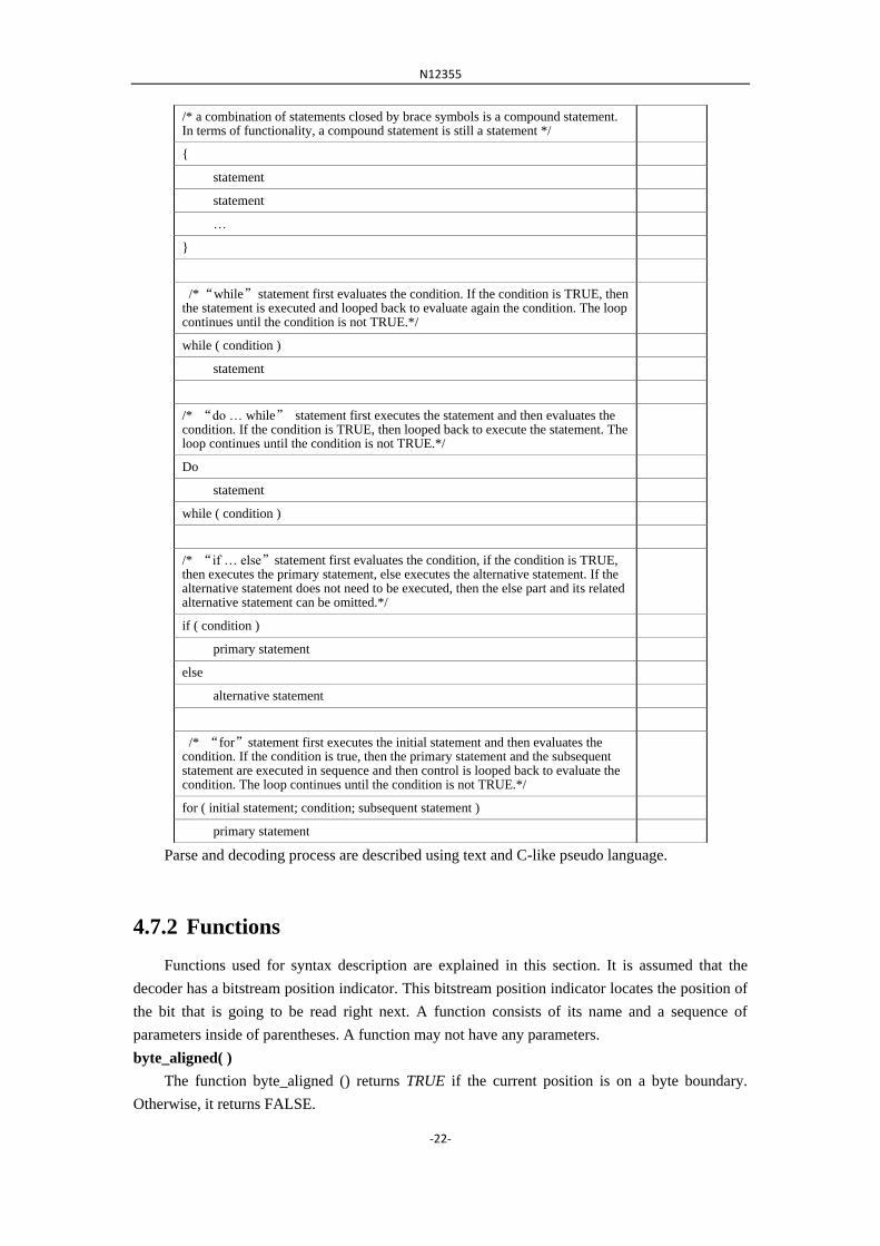
/* a combination of statements closed by brace symbols is a compound statement. In terms of functionality, a compound statement is still a statement */
{
statement
statement
…
}
/* “while” statement first evaluates the condition. If the condition is TRUE, then the statement is executed and looped back to evaluate again the condition. The loop continues until the condition is not TRUE.*/
while ( condition )
statement
/* “do … while” statement first executes the statement and then evaluates the condition. If the condition is TRUE, then looped back to execute the statement. The loop continues until the condition is not TRUE.*/
Do
statement
while ( condition )
/* “if … else”statement first evaluates the condition, if the condition is TRUE, then executes the primary statement, else executes the alternative statement. If the alternative statement does not need to be executed, then the else part and its related alternative statement can be omitted.*/
if ( condition )
primary statement
else
alternative statement
/* “for”statement first executes the initial statement and then evaluates the condition. If the condition is true, then the primary statement and the subsequent statement are executed in sequence and then control is looped back to evaluate the condition. The loop continues until the condition is not TRUE.*/
for ( initial statement; condition; subsequent statement )
primary statement
Parse and decoding process are described using text and C-like pseudo language.
4.7.2 Functions
Functions used for syntax description are explained in this section. It is assumed that the
decoder has a bitstream position indicator. This bitstream position indicator locates the position of
the bit that is going to be read right next. A function consists of its name and a sequence of
parameters inside of parentheses. A function may not have any parameters.
byte_aligned( )
The function byte_aligned () returns TRUE if the current position is on a byte boundary.
Otherwise, it returns FALSE.

N12355
-23-
next_bits( n )
The function returns the next n bits from the bitstream, MSB first. The current bitstream
position indicator is not changed. If the remaining number of bits to be read are less than n, then
returns 0.
byte_aligned_next_bits( n )
If the current position of the bitstream is not byte aligned, returns n bits beginning from the
next byte aligned position, MSB first. The current bitstream position indicator is not changed. If
the current position of the bitstream is byte aligned, returns n bits from the current position, MSB
first. The current bitstream position is not changed. If the remaining number of bits to be read is
less than n, then returns 0.
next_start_code( )
The next_start_code() function locates the next start code. It is defined in the table below.
next_start_code() { descriptor
stuffing_bit '1'
while ( ! byte_aligned() )
stuffing_bit '0'
while ( next_bits(24) != '0000 0000 0000 0000 0000 0001' )
stuffing_byte '0000 0000'
}
The stuffing_bytes shall appear after a picture header and before a slice header start code.
is_end_of_slice( )
This function tests if the current position is at the end of the slice. The function‟s definition is
shown in the table below.
is_end_of_slice () { descriptor
if ( byte_aligned ( ) {
if ( next_bits(32) == 0x80000001
return TRUE; // end of slice
}
else {
if ( (byte_aligned_next_bits(24) == 0x000001) && is_stuffing_pattern() )
return TRUE; // end of slice
}
return FALSE;
}
is_stuffing_pattern( )
This function tests whether the remaining bits of the current byte or the next byte (in case the
current position is byte aligned), are stuffing bits. The function‟s definition is shown in the table
below.
is_stuffing_pattern () { descriptor
if ( next_bits(8-n) == ( 1<< (7-n) ) ) // n:0~7,for shifting the bitstream position indicator in the current byte, when n is 0, the bitstream position indicator indicates the MSB of the current byte.
return TRUE;
N12355
-24-
Else
return FALSE;
}
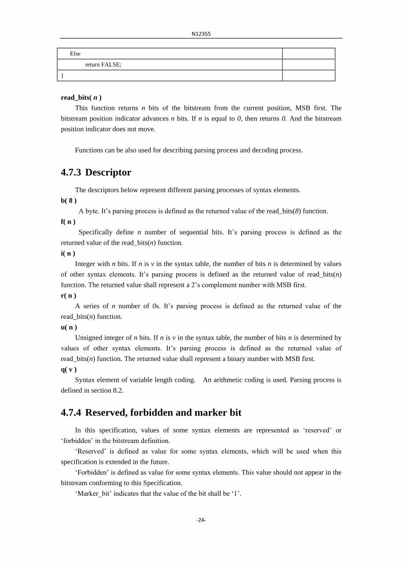
read_bits( n )
This function returns n bits of the bitstream from the current position, MSB first. The
bitstream position indicator advances n bits. If n is equal to 0, then returns 0. And the bitstream
position indicator does not move.
Functions can be also used for describing parsing process and decoding process.
4.7.3 Descriptor
The descriptors below represent different parsing processes of syntax elements.
b( 8 )
A byte. It‟s parsing process is defined as the returned value of the read_bits(8) function.
f( n )
Specifically define n number of sequential bits. It‟s parsing process is defined as the
returned value of the read_bits(n) function.
i( n )
Integer with n bits. If n is v in the syntax table, the number of bits n is determined by values
of other syntax elements. It‟s parsing process is defined as the returned value of read_bits(n)
function. The returned value shall represent a 2‟s complement number with MSB first.
r( n )
A series of n number of 0s. It‟s parsing process is defined as the returned value of the
read_bits(n) function.
u( n )
Unsigned integer of n bits. If n is v in the syntax table, the number of bits n is determined by
values of other syntax elements. It‟s parsing process is defined as the returned value of
read_bits(n) function. The returned value shall represent a binary number with MSB first.
q( v )
Syntax element of variable length coding. An arithmetic coding is used. Parsing process is
defined in section 8.2.
4.7.4 Reserved, forbidden and marker bit
In this specification, values of some syntax elements are represented as „reserved‟ or
„forbidden‟ in the bitstream definition.
„Reserved‟ is defined as value for some syntax elements, which will be used when this
specification is extended in the future.
„Forbidden‟ is defined as value for some syntax elements. This value should not appear in the
bitstream conforming to this Specification.
„Marker_bit‟ indicates that the value of the bit shall be „1‟.

N12355
-25-
‟Reserved_bits‟ represents that values for some syntax elements are reserved, which will be
used when this specification is extended in the future. The decode processing shall ignore these
bits.
5 Bitstream syntax and semantics
5.1 Structure of coded video data
This section explains the structure of coded bitstream, relationships between layers and
processing order.
5.1.1 Video sequence
The highest syntactic structure of the coded video bitstream is the video sequence. A video
sequence commences with a sequence header which is followed by one or more coded pictures. In
front of each picture, a picture header is present. The order of the coded pictures in the coded
bitstream is the bitstream order. The bitstream order is same as the decoding order. The decoding
order is not necessarily same as the display order. The video sequence is terminated by a
sequence_end_code.
This Specification deals with coding of progressive sequences.
A frame consists of three sample matrices of integers: a luminance sample matrix (Y), and two
chrominance sample matrices (Cb and Cr).
An element of each color sample matrix has integer value. The relationship between these Y, Cb
and Cr components and the primary (analogue) Red, Green and Blue Signals, the chromaticity of these
primaries and the transfer characteristics of the source frame may be specified in the bitstream. This
information does not affect the decoding process.
The output of the decoding process is a series of frames. Reconstructed frames are separated
in time by a frame period.
5.1.2 Sequence header
A video sequence header commences with sequence header start code and is followed by a series
of coded picture data. A sequence header is allowed to be repeatedly present in bitstream. This
sequence header is called repeat sequence header. The main purpose of repeat sequence header is
providing with random access functionality. The first coded picture after a sequence header should be I
frame. The first P frame after a sequence header only refers to pictures appeared after the sequence
header. If a bitstream is edited so that all of the data preceding any of the repeat sequence headers is
removed (or alternatively random access is made to that sequence header), then the resulting bitstream
shall be a legal bitstream that complies with this specification.

N12355
-26-
5.1.3 Picture
A picture is a frame. Its coded data starts with a picture start code and ends with a sequence
start code, a sequence end code or another picture start code. The decode process of a picture
includes parsing processing and decoding processing.
5.1.4 Color format
In 4:2:0 format, the Cb and Cr matrices shall be one half the size of the Y-matrix in both
horizontal and vertical dimensions. The luminance and chrominance samples are positioned as
shown in Figure 1.
Luminance sample Chrominance sample
Figure 1 Position of luminance and chrominance samples in 4:2:0 format
5.1.5 Picture types
This specification defines 2 types of decoded pictures:
1) a non-bidirectional Predictive-decoded (P);
2) a Bidirectional predictive-decoded (B) picture.
5.1.6 Order between pictures
If there is no B frames in a video sequence, the decoding order and the display order are same.
If a video sequence contains more than one B frame, the decoding order is not same as the display
order so that before the decoded pictures are output to display, they need to be reordered. The
re-ordering is performed according to the following rules:
1) If there are no decoded frames, and the current frame is not coded with only intra blocks,
no frame is output. If there are no decoded frames, and the current frame is coded with
only intra blocks, the frame is reconstructed and marked as P-frame;
2) If the current frame to decode is a B-frame, the output frame is the frame reconstructed
from that B frame;
3) If the current frame to decode is a P-frame and a previously decoded P-frame exists, the
output frame is the frame reconstructed from the previously decoded P-frame. If
previously decoded P-frame does not exist, no frame is output;

N12355
-27-
4) After all the steps are finished, if there are still frames not output in the buffer, output
those frames.
The following is an example for explaining re-ordering: there are two coded B-frames
between successive coded P-frames. The P-frame with only intra coded blocks is marked as “I”.
Frame „1I‟ is used to form a prediction for frame „4P‟. Frames „4P‟ and „1I‟ are both used to form
predictions for frames „2B‟ and „3B‟. Therefore the order of coded frames in the coded sequence
shall be „1I‟, „4P‟, „2B‟, „3B‟. However, the decoder shall display them in the order „1I‟, „2B‟,
„3B‟, „4P‟.
Encoder input order:
1 2 3 4 5 6 7 8 9 1
0
1
1
1
2
1
3
I B B P B B P B B I B B P
Decoding order :
1 4 2 3 7 5 6 1
0
8 9 1
3
1
1
1
2
I P B B P B B I B B P B B
Decoder output (display order):
1 2 3 4 5 6 7 8 9 1
0
1
1
1
2
1
3
I B B P B B P B B I B B P
5.1.7 Reference picture
At most two reference pictures can be used for P or B frame coding. P frame can use one
forward frames as reference; B frame can refer to one forward reference frame and one backward
reference frame.
In a situation where a pixel indicated by a motion vector is outside of the reference picture
boundary, the nearest integer sample inside a picture from the indicated outside position shall be
used for boundary padding. For luminance sample matrix, pixels in a reference block shall not
surpass 16 pixels both horizontally and vertically from the reference picture boundary. For
chrominance sample matrix, if color format is 4:2:0, pixels in a reference block shall not surpass 8
pixels both horizontally and vertically from the reference picture boundary.
5.1.8 Slice
Slice is a series of one or more macroblocks in the order of raster scan. Macroblocks of a slice
shall not overlap and also slices shall not overlap. The position of slices may change from picture
to picture. The decoding process of a macroblock inside a slice should not use data in the other
slices of the same picture.

N12355
-28-
5.1.9 Macroblock
A picture is partitioned into macroblocks. The top-left corner of macroblock shall not surpass
the boundary of picture. For interlace case, when two coded fields for a frame appears in sequence
in the bitstream, any macroblock shall consist of pixels from the same field data.
A macroblock is partitioned for motion compensation as shown in Figure 3. The number
inside a rectangle indicates the order of motion vectors and reference indices after partitioning in
the bitstream.
Figure 3 Macroblock partition
5.1.10 8x8 block
For 4:2:0 format, a macroblock contains 4 blocks of 8x8 luminance (Y) block and 2
chrominance blocks of 8x8 size (one Cb and one Cr). The numbers shown in Figure 4 indicate the
order of 8x8 blocks in a macroblock.
04 5
1
2 3
Y Cb Cr
Figure 4 partitioning of a macroblock into 8x8 blocks (4:2:0 format)
5.1.11 4x4 block
For 4:2:0 format, a macroblock contains 16 blocks of 4x4 luminance (Y) block and four 4x4
blocks of Cb, and four 4x4 blocks of Cr. The numbers shown in Figure 5 indicate the order of 4x4
blocks in a macroblock.
0 1 4 5
2 3 6 7
8 9 12 13
10 11 14 15
0 1
2 3
0 1
2 3
Y Cb Cr
Figure 5 partitioning of a macroblock into 4x4 blocks (4:2:0 format)
0
0 1
2 3
A 16x16 luma block
and its corresponding
chroma block
Four 8x8 luma blocks
and their corresponding
chroma blocks
N12355
-29-
5.2 Bitstream syntax
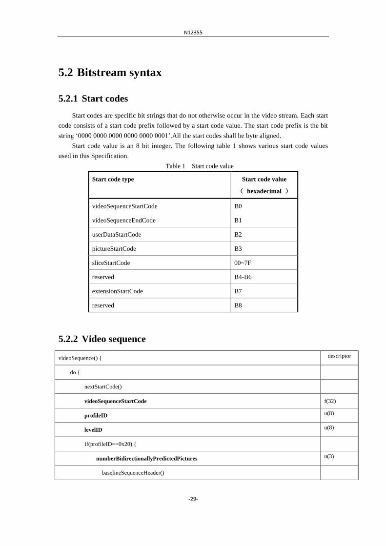
5.2.1 Start codes
Start codes are specific bit strings that do not otherwise occur in the video stream. Each start
code consists of a start code prefix followed by a start code value. The start code prefix is the bit
string „0000 0000 0000 0000 0000 0001‟.All the start codes shall be byte aligned.
Start code value is an 8 bit integer. The following table 1 shows various start code values
used in this Specification.
Table 1 Start code value
Start code type Start code value
( hexadecimal )
videoSequenceStartCode B0
videoSequenceEndCode B1
userDataStartCode B2
pictureStartCode B3
sliceStartCode 00~7F
reserved B4-B6
extensionStartCode B7
reserved B8
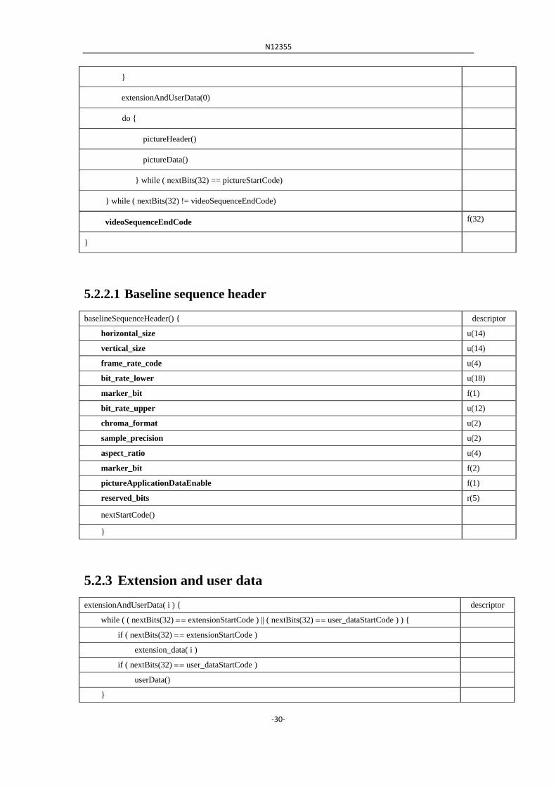
5.2.2 Video sequence
videoSequence() { descriptor
do {
nextStartCode()
videoSequenceStartCode f(32)
profileID u(8)
levelID u(8)
if(profileID==0x20) {
numberBidirectionallyPredictedPictures u(3)
baselineSequenceHeader()
N12355
-30-
}
extensionAndUserData(0)
do {
pictureHeader()
pictureData()
} while ( nextBits(32) == pictureStartCode)
} while ( nextBits(32) != videoSequenceEndCode)
videoSequenceEndCode f(32)
}
5.2.2.1 Baseline sequence header
baselineSequenceHeader() { descriptor
horizontal_size u(14)
vertical_size u(14)
frame_rate_code u(4)
bit_rate_lower u(18)
marker_bit f(1)
bit_rate_upper u(12)
chroma_format u(2)
sample_precision u(2)
aspect_ratio u(4)
marker_bit f(2)
pictureApplicationDataEnable f(1)
reserved_bits r(5)
nextStartCode()
}
5.2.3 Extension and user data
extensionAndUserData( i ) { descriptor
while ( ( nextBits(32) extensionStartCode ) || ( nextBits(32) user_dataStartCode ) ) {
if ( nextBits(32) extensionStartCode )
extension_data( i )
if ( nextBits(32) user_dataStartCode )
userData()
}

N12355
-31-
}
5.2.3.1 Extension data
extensionData( i ) { descriptor
while (nextBits(32) == extensionStartCode ) {
extensionStartCode f(32)
while ( nextBits(24) != '0000 0000 0000 0000 0000 0001' )
extensionDataByte u(8)
}
}
5.2.3.2 User data
extensionData( i ) { descriptor
while (nextBits(32) == extensionStartCode ) {
extensionStartCode f(32)
while ( nextBits(24) != '0000 0000 0000 0000 0000 0001' )
extensionDataByte u(8)
}
}
5.2.4 Picture
5.2.4.1 Picture header
pictureHeader() { descriptor
pictureStartCode u(32)
if (pictureApplicationDataEnable) {
pictureApplicationData u(18)
marker_bit f(1)
pictureApplicationData u(18)
marker_bit f(1)
pictureApplicationData u(2)
}
fixed_picture_qp u(1)
picture_qp u(6)
vbs_enable u(1)
nextStartCode()

N12355
-32-
}
5.2.4.2 Picture data
pictureData() { descriptor
do {
slice()
} while ( nextBits(32) == sliceStartCode )
nextStartCode()
}
5.2.5 Slice
The MPEG-2 style slice is used in the ITM.
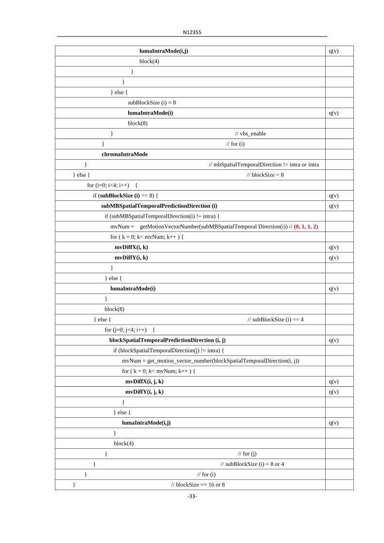
5.2.6 Macroblock
macroblock() { descriptor
mb_skip_flag q(v)
mb_qp_delta q(v)
blockSize // (16 or 8) q(v)
if (blockSize == 16) {
mbSpatialTemporalDirection // (0: intra, 1: fwd, 2: bwd, 3: bi,) q(v)
if (mbSpatialTemporalDirection != intra) {
mvNum = getMotionVectorNumber(mbSpatialTemporalDirection) // (0, 1, 1, 2)
for ( i = 0; i < mvNum; i++ ) {
mvDiffX(i) q(v)
mvDiffY(i) q(v)
}
for ( i = 0; i < 4; i++ ) {
block (8)
}
} else{ // intra macroblock
for (i=0, i<4, i++) {
if (vbs_enable) {
if subBlockSize (i) = 8 { // (8 or 4) q(v)
lumaIntraMode(i) q(v)
block(8)
} else { // subBlockSize (i) = 4
for (j=0, j<4, j++)
N12355
-33-
lumaIntraMode(i,j) q(v)
block(4)
}
}
} else {
subBlockSize (i) = 8
lumaIntraMode(i) q(v)
block(8)
} // vbs_enable
} // for (i)
chromaIntraMode
} // mbSpatialTemporalDirection != intra or intra
} else { // blockSize = 8
for (i=0; i<4; i++) {
if (subBlockSize (i) == 8) { q(v)
subMBSpatialTemporalPredictionDirection (i) q(v)
if (subMBSpatialTemporalDirection(i) != intra) {
mvNum = getMotionVectorNumber(subMBSpatialTemporal Direction(i)) // (0, 1, 1, 2)
for ( k = 0; k< mvNum; k++ ) {
mvDiffX(i, k) q(v)
mvDiffY(i, k) q(v)
}
} else {
lumaIntraMode(i) q(v)
}
block(8)
} else { // subBlockSize (i) == 4
for (j=0; j<4; i++) {
blockSpatialTemporalPredictionDirection (i, j) q(v)
if (blockSpatialTemporalDirection(j) != intra) {
mvNum = get_motion_vector_number(blockSpatialTemporalDirection(i, j))
for ( k = 0; k< mvNum; k++ ) {
mvDiffX(i, j, k) q(v)
mvDiffY(i, j, k) q(v)
}
} else {
lumaIntraMode(i,j) q(v)
}
block(4)
} // for (j)
} // subBlockSize (i) = 8 or 4
} // for (i)
} // blockSize == 16 or 8
N12355
-34-
block(8) // Cr coeffs in 8x8
block(8) // Cb coeffs in 8x8
}
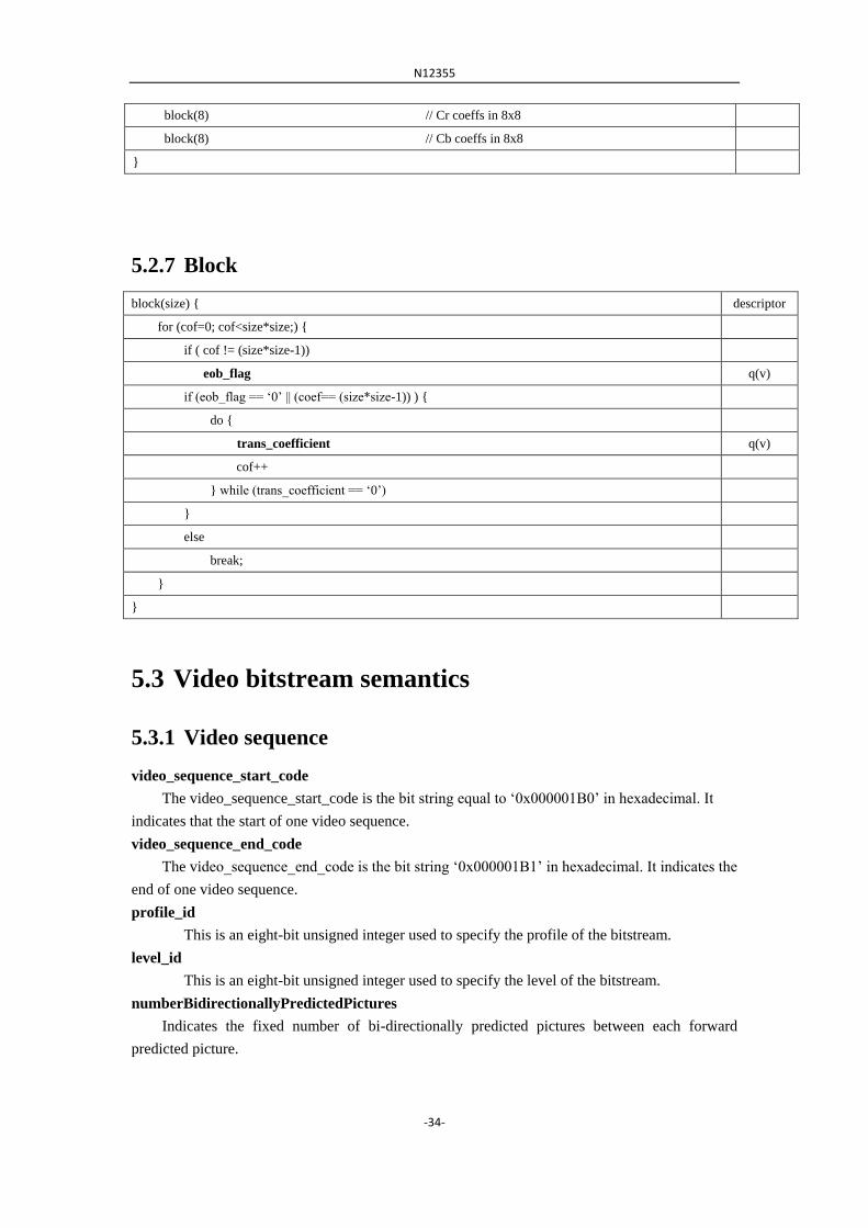
5.2.7 Block
block(size) { descriptor
for (cof=0; cof<size*size;) {
if ( cof != (size*size-1))
eob_flag q(v)
if (eob_flag == „0‟ || (coef== (size*size-1)) ) {
do {
trans_coefficient q(v)
cof++
} while (trans_coefficient == „0‟)
}
else
break;
}
}
5.3 Video bitstream semantics
5.3.1 Video sequence
video_sequence_start_code
The video_sequence_start_code is the bit string equal to „0x000001B0‟ in hexadecimal. It
indicates that the start of one video sequence.
video_sequence_end_code
The video_sequence_end_code is the bit string „0x000001B1‟ in hexadecimal. It indicates the
end of one video sequence.
profile_id
This is an eight-bit unsigned integer used to specify the profile of the bitstream.
level_id
This is an eight-bit unsigned integer used to specify the level of the bitstream.
numberBidirectionallyPredictedPictures
Indicates the fixed number of bi-directionally predicted pictures between each forward
predicted picture.

N12355
-35-
5.3.2 Sequence header
horizontal_size
The horizontal_size is a 14-bit unsigned integer used to specify the width of the intended
display‟s region of the luminance component of pictures in samples.
The width of the encoded luminance component of pictures in macroblocks, MBwidth, is
calculated as:
MbWidth = (horizontal_size + 15) / 16。
The value of horizontal_size should not be zero. The unit of horizontal_size should be image
samples per line. The displayable part is left-aligned in the decoded pictures.
vertical_size
The vertical_size is a 14-bit unsigned integer used to specify the height of the intended
display‟s region (it‟s top-aligned in the decoded pictures) of the luminance component of pictures
in lines.
The height of the encoded luminance component of frame pictures in macroblocks,
MbHeight, is calculated as
MbHeight = (vertical_size + 15) / 16
The value of vertical_size should not be zero. The unit of horizontal_size should be the lines
of image samples.
Note: the relationship between horizontal_size, vertical_size and the image borders is
illustrated in figure 6. In figure 6, the solid line represents the border of the displayable part. Its
width and height are specified by horizontal_size and vertical_size respectively. The dotted line
represents the border of the pitcures. Its width and height are specified by MbWidth and
MbHeight respectively. For example, if horizontal_size is 1920 and vertical_size is 1080, then
MbWidth 16 equals to 1920 and MbHeight 16 equals to 1088.
Figure 6 Illustration of the image border
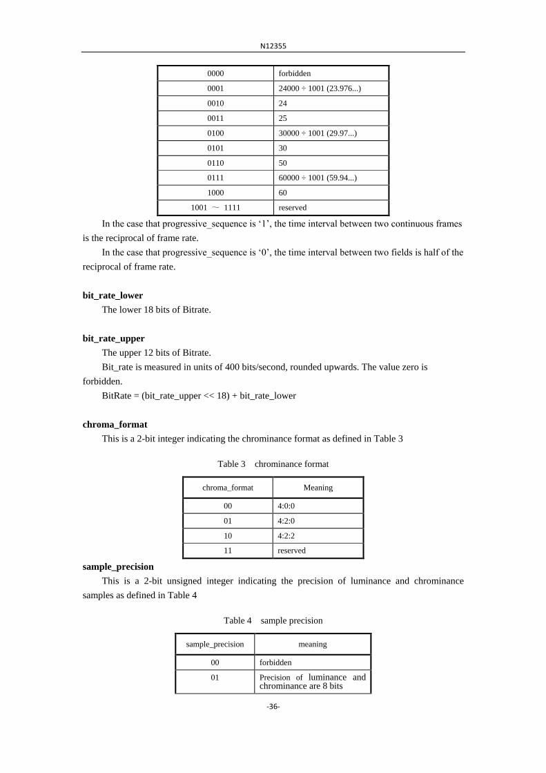
frame_rate_code
This is a 4-bit unsigned integer indicating the frame rate as defined in the Table 2.
Table 2 the frame rate code
frame_rate_code Frame rate
N12355
-36-
0000 forbidden
0001 24000 ÷ 1001 (23.976...)
0010 24
0011 25
0100 30000 ÷ 1001 (29.97...)
0101 30
0110 50
0111 60000 ÷ 1001 (59.94...)
1000 60
1001 ~ 1111 reserved
In the case that progressive_sequence is „1‟, the time interval between two continuous frames
is the reciprocal of frame rate.
In the case that progressive_sequence is „0‟, the time interval between two fields is half of the
reciprocal of frame rate.
bit_rate_lower
The lower 18 bits of Bitrate.
bit_rate_upper
The upper 12 bits of Bitrate.
Bit_rate is measured in units of 400 bits/second, rounded upwards. The value zero is
forbidden.
BitRate = (bit_rate_upper << 18) + bit_rate_lower
chroma_format
This is a 2-bit integer indicating the chrominance format as defined in Table 3
Table 3 chrominance format
chroma_format Meaning
00 4:0:0
01 4:2:0
10 4:2:2
11 reserved
sample_precision
This is a 2-bit unsigned integer indicating the precision of luminance and chrominance
samples as defined in Table 4
Table 4 sample precision
sample_precision meaning
00 forbidden
01 Precision of luminance and chrominance are 8 bits

N12355
-37-
10 reserved
11 reserved
aspect_ratio
This is a 4-bit unsigned integer indicating the Sample Aspect Ratio (SAR) or the Display
Aspect Ratio (DAR) as defined in Table 5.
Table 5 aspect ratio
aspect_ratio Sample Aspect Ratio
(SAR)
Display Aspect Ratio
(DAR)
0000 forbidden forbidden
0001 1.0 –
0010 – 4 ÷ 3
0011 – 16 ÷ 9
0100 – 2.21 ÷ 1
0101 ~ 1111 – reserved
If the sequence_display_extension() is not present in the bitstream, then the entire
reconstructed frame is intended to be mapped to the entire active region of the display. The sample
aspect ratio
may be calculated as follows:
SAR = DAR vertical_size horizontal_size
NOTE - In this case, horizontal_size and vertical_size are constrained by the SAR of the
source and the DAR selected.
If the sequence_display_extension() is present then the sample aspect ratio may be calculated
as:
SAR = DAR display_vertical_size display_horizontal_size
pictureApplicationDataEnable
This is one bit flag. „1‟ indicates that pictureApplicationData appears in the picture header.
„0‟ indicates that pictureApplicationData does not appear in the picture header.
5.3.3 Extension data and user data
5.3.3.1 Extension data
extension_start_code
The extension_start_code is the bit string „0x000001B5‟ in hexadecimal. It identifies the
beginning of video extension data.
extension_data_byte
The extension_data_byte is an 8-bit unsigned integer which is used for identifying the video
extension data.

N12355
-38-
5.3.3.2 user data
user_data_start_code
The user_data_start_code is the bit string „0x000001B2‟ in hexadecimal. It identifies the
beginning of user data. The user data continues until receipt of another start code.
user_data
This is an 8-bit integer. User data is defined by users for their specific applications. In the
series of consecutive user_data bytes there shall not be a string of 23 or more consecutive zero
bits.
5.3.4 Picture
5.3.4.1 Picture header
picture_start_code
The picture_start_code is the bit string 0x000001B3‟ in hexadecimal. It is the startcode of
aframes and identifies the beginning of a frame.
pictureApplicationData
may be used by an application.
fixed_picture_qp
This is one bit flag. „1‟ indicates the quantization parameter does not change in the picutre. „0‟
indicates the quantization parameter may change.
picture_qp
This is 6-bit unsigned integer. It specifies the quantization parameter of the picture, with a
range from 0 to 63 inclusive.
vbs_enable
This is one bit flag. „1‟ indicates that current decoded picture can use 4x4 transforms. „0‟
indicates 4x4 luminance blocks are not allowed. If this flag is not present in the picture header, it
is set to be „0‟.
5.3.5 Slice
start_code_prefix
The start_code_prefix is the 24-bit bit string „0x000001‟ in hexadecimal.
5.3.6 Macroblock
mb_skip_flag
It equal to 1 specifies that the current macroblock is skiped and equal to 0 specifies that the
current macroblock is not skipped.
mb_qp_delta
It gives the increment of current quantization coefficients relative to predicted quantization
coefficients, with a range of -32 to 31. The QP of the current Macroblock QPMB is equal to
picture_qp + mb_qp_delta. If mb_qp_delta is not present in the picture header, it is set to be 0.

N12355
-39-
blockSize
It equal to 16 specifies that the current macroblock is coded as one block with 16x16-size and
equal to 8 specifies that the current macroblock is divided into four 8x8 blocks.
mbSpatialTemporalDirection
It equal to 0 specifies that the current block is intra coded, equal to 1 specifies that the current
block is forward predicted, equal to 2 specifies that the current block is backward predicted and
equal to 3 specifies that the current block is bi-predicted.
subBlockSize
It equal to 8 specifies that the current 8x8 block is coded as one block and equal to 4 specifies
that the current block is divided into four 4x4 blocks.
subMBSpatialTemporalPredictionDirection
It equal to 0 specifies that the current block is intra coded, equal to 1 specifies that the current
block is forward predicted, equal to 2 specifies that the current block is backward predicted and
equal to 3 specifies that the current block is bi-predicted.
blockSpatialTemporalPredictionDirection
It equal to 0 specifies that the current block is intra coded, equal to 1 specifies that the current
block is forward predicted, equal to 2 specifies that the current block is backward predicted and
equal to 3 specifies that the current block is bi-predicted.
lumaIntraMode
It is used to determine the intra prediction mode of a luma block. It equal to 0 specifies that
the prediction mode for the current block is horizontal prediction, equal to 1 specifies that it is
vertical prediction and equal to 2 specifies that it is direct prediction. If it is not present, it is set to be
2.
chromaIntraMode
It is used to determine the intra prediction mode of a luma block. It equal to 0 specifies that
the prediction mode for the current block is horizontal prediction, equal to 1 specifies that it is
vertical prediction and equal to 2 specifies that it is direct prediction. If it is not present, it is set to be
2.
mvDiffX
mvDiffY
They define the values of motion vector differences. It is in one-half luma sample unit, with
range -2048 to 2047 (the range is -1024 to 1023.75 in luma sample units). Decoder decodes all
forward motion vectors first, and then decodes all backward motion vectors. See subclause 8.2 for
parsing process.
5.3.7 Block
eob_flag
This flag, when set to „1‟, indicates that trans_coefficient of current block have not been decoded
completely, there is still non-zero trans_coefficient after it.
trans_coefficient

N12355
-40-
Transform coefficient, could be either non-zero value or zero value.

N12355
-41-
6 Video decoding process
This chapter defines video decoding process.
The video decoding process is shown in figure 7.
Variable Length
Decoding
Inverse Quantis-
ation
Inverse Scan
Motion Compen-
sation
Inverse DCT
Frame- store
Memory
f[y][x]F[v][u]
QF[v][u]QFS[n]
Coded Data
Decoded samples
d[y][x]
Figure 7 video decoding process
6.1 High-level syntax structure
The reconstructed frames shall be output from the decoding process at regular intervals of the
frame period.
6.2 Variable length decoding
Option-1 video uses binary arithmetic code based on QM-coder. This method uses definite
state auto machine to running after the change of the probability for one or more syntax elements
which share the same probability distributing, and code or decoder the syntax elements with
binary arithmetic code based on the context.
The decoder of QM-coder is defined as
typedef struct qcoder {
unsigned long interval;
unsigned long code;
int code_bits;
}
There are two registers in QM-coder: the probability interval register and the code register.
QM-coder uses 16bit unsigned integer to estimate the probability. The initial value for the interval
is 0x10000, and the renormalization boundary value is 0x8000. The definition of interval and code
register is in Table 6.
Table 6 interval and code register
Interval 00000000 00000000 vvvvvvvv vvvvvvvv
Code xxxxxxxx xxxxxxxx bbbbbbbb 00000000
N12355
-42-
In interval register, “v” bits stand the size of the interval in current. And in code register, “x”
bits are the sub-interval bits in current, “b” bits are the value of the next input byte from the bit
stream.
Definite state auto machine defines the rules for the probability estimation and changing. Its
structure is :
typedef struct prob_state {
int lps_interval;
int next_state_lps;
int next_state_mps;
int do_switch_mps;
} prob_state_t;
Context(prob_context_t) is made up of two things: the current state from definite state auto
machine and the next probability prediction. The structure is defined below.
typedef struct prob_context {
int mps;
int state;
prob_state_t* prob_fsm;
} prob_context_t;
In entropy decoding process, there are mainly two methods which can be found in Table 7.
Table 7 Mainly methods in entropy decoding
Methods Function
initializeArithmeticCoder () Initialization of the qcoder decoder engine
qcoder_decode_symbol(prob_context_t context) Output the binary value based on the input context
In itializeArithmeticCoder() is to initialize the context value of the syntax elements in the
qcoder decoder. And qcoder_decode_symbol(prob_context_t context) output the bits of “0” and
“1” based on the context.
6.2.1 Initialization of the qcoder Decoder
In initializeArithmeticCoder() processing, every syntax element has the initial value. There
are many different but independent syntax elements, so there are also many different but
independent contexts. Every context can predict the next state according to their own state
machine, and update the state machine. The flow chart of the Initialization processing is:

N12355
-43-
Figure 8 The initialization of decoder
The syntax elements and the corresponding context initial values are in Table 8.
Table 8 syntax elements and the corresponding contexts initial values
Contexts syntax elements value
mps state prob_fsm
cx_eq_prob N/A 0 0 eq_prob_fsm
OTHERS All other syntaxes 0 0 standard_prob_fsm
eq_prob_fsm and standard_prob_fsm are probability prediction state machine, which is
obtained from by certain learning processing. This is the same with JPEG Annex-D, which can be
found in Annex-A.
6.2.2 Entropy decoding processing
qcoder_decode_symbol(prob_context_t context) runs with certain context as its input, and
qcoder_init()
interval = 0x10000
code = 0
code += (input_byte() << 8)
code <<= 8
code += (input_byte() << 8)
code <<= 8;
code += (input_byte() << 8)
code_bits = 8
context initilization
return

N12355
-44-
produce a binary value. The flow chart is as below.
Figure 2 Flow chart for entropy decoding
MPS conditional exchanging processing Cond_MPS_EX(prob_context_t c) is as Figure 10.
qcoder_decode_symbol(prob_context_t c)
interval -= c.lps_interval
code < interval
Yes
Yes
b = Cond_MPS_EX(c)
Renormalize()
b = c.mps
No
b = Cond_LPS_EX(c)
Renormalize()
return b
No
interval < 0x8000

N12355
-45-
Figure 10 Flow chart of MPS conditional exchanging processing
LPS conditional exchanging processing Cond_LPS_EX(prob_context_t c) is as Figure 11.
Figure 11 Flow chart of LPS conditional exchanging processing
Cond_LPS_EX(prob_context_t c)
interval < c.lps_interval
No Yes
b = c.mps
code -= interval
interval = c.lps_interval
b = 1 - c.mps
code -= interval
interval = c.lps_interval
MPS_estimate(c)
Cond_MPS_EX(prob_context_t c)
interval < c.lps_interval
No Yes
b = 1 – c.mps b = c.mps
MPS_estimate(c)
return b
LPS_estimate(c)
LPS_estimate(c)
return b
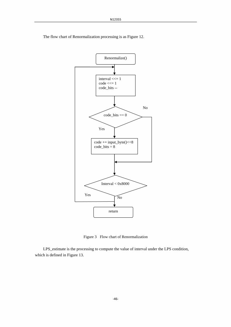
N12355
-46-
The flow chart of Renormalization processing is as Figure 12.
Figure 3 Flow chart of Renormalization
LPS_estimate is the processing to compute the value of interval under the LPS condition,
which is defined in Figure 13.
Renormalize()
interval <<= 1
code <<= 1
code_bits --
code_bits == 0
No
code += input_byte()<<8
code_bits = 8
Interval < 0x8000
Yes
No
return
Yes
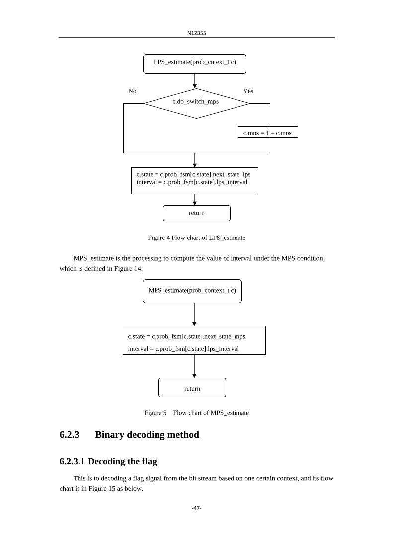
N12355
-47-
Figure 4 Flow chart of LPS_estimate
MPS_estimate is the processing to compute the value of interval under the MPS condition,
which is defined in Figure 14.
Figure 5 Flow chart of MPS_estimate
6.2.3 Binary decoding method
6.2.3.1 Decoding the flag
This is to decoding a flag signal from the bit stream based on one certain context, and its flow
chart is in Figure 15 as below.
MPS_estimate(prob_context_t c)
c.state = c.prob_fsm[c.state].next_state_mps
interval = c.prob_fsm[c.state].lps_interval
return
LPS_estimate(prob_cntext_t c)
c.do_switch_mps
Yes No
c.mps = 1 – c.mps
c.state = c.prob_fsm[c.state].next_state_lps
interval = c.prob_fsm[c.state].lps_interval
return
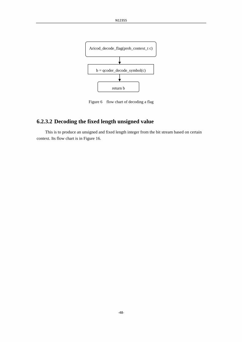
N12355
-48-
Figure 6 flow chart of decoding a flag
6.2.3.2 Decoding the fixed length unsigned value
This is to produce an unsigned and fixed length integer from the bit stream based on certain
context. Its flow chart is in Figure 16.
Aricod_decode_flag(prob_context_t c)
b = qcoder_decode_symbol(c)
return b
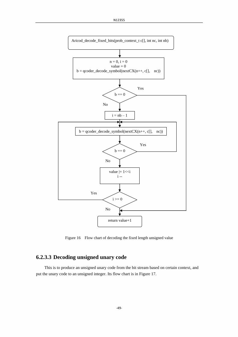
N12355
-49-
Figure 16 Flow chart of decoding the fixed length unsigned value
6.2.3.3 Decoding unsigned unary code
This is to produce an unsigned unary code from the bit stream based on certain context, and
put the unary code to an unsigned integer. Its flow chart is in Figure 17.
Aricod_decode_fixed_bits(prob_context_t c[], int nc, int nb)
n = 0, i = 0
value = 0
b = qcoder_decode_symbol(nextCX(n++, c[], nc))
b == 0
Yes
i = nb – 1
b = qcoder_decode_symbol(nextCX(n++, c[], nc))
b == 0
No
No
value |= 1<<i
i --
i >= 0
Yes
No
return value+1
Yes

N12355
-50-
Figure 7 Flow chart of Decoding unsigned unary code
6.2.3.4 Decoding signed unary code
This is to produce a signed unary code from the bit stream based on certain context, and put
the unary code into a signed integer. Its flow chart is in Figure 18.
Aricod_decode_unary(prob_context_t c[], int nc)
n = 0
value = 0
b = qcoder_decode_symbol(nextCX(n++, c[], nc))
b == 0
value ++
return value
Yes
No

N12355
-51-
Figure 18 Flow chart of decoding signed unary code
6.2.3.5 Decoding unsigned truncated unary code
This is to produce an unsigned truncated unary code from the bit stream based on certain
context, and put the truncated unary code into an unsigned integer. Its flow chart is in Figure 19.
Aricod_decode_signed_unary(prob_context_t c[], int nc)
n = 0
value = 0
b = qcoder_decode_symbol(nextCX(n++, c[], nc))
b == 0
value ++
return value
Yes
No
pos = value & 1
value += 1
value >>= 1
Value = value * (pos?1:-1)

N12355
-52-
Figure 19 Flow chart of decoding unsigned trunary code
6.2.3.6 Decoding unsigned Exp-Golomb code
This is to produce an unsigned Exp-Golomb code from the bit stream based on certain
context, and put the Exp-Golomb code into an unsigned integer. Its flow chart is in Figure 20.
Aricod_decode_truncated_unary(prob_context_t c[], int nc, int maxValue)
n = 0
value = 0
b = qcoder_decode_symbol(nextCX(n++, c[], nc))
value < maxValue && b!=0
value ++
Yes
Return value
No
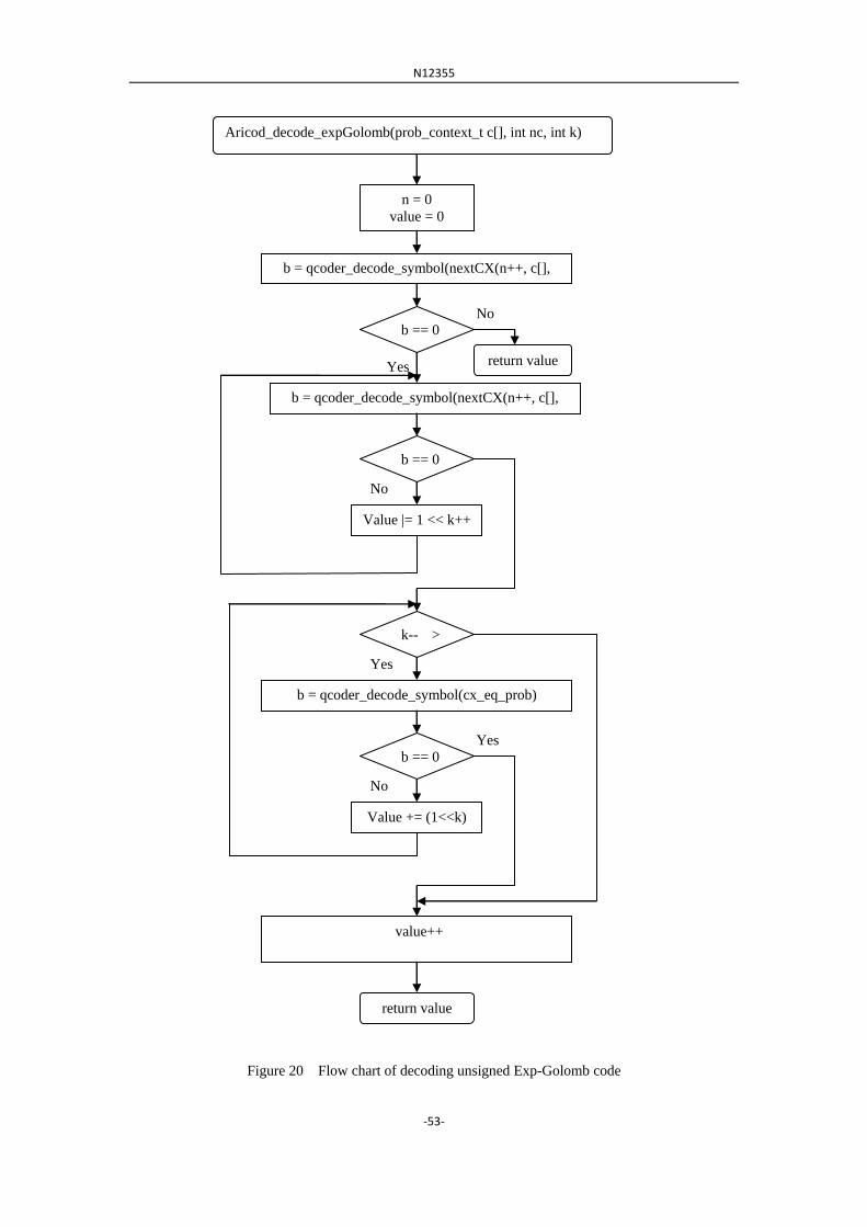
N12355
-53-
Figure 20 Flow chart of decoding unsigned Exp-Golomb code
Aricod_decode_expGolomb(prob_context_t c[], int nc, int k)
n = 0
value = 0
b == 0
b = qcoder_decode_symbol(nextCX(n++, c[],
nc))
return value
b = qcoder_decode_symbol(nextCX(n++, c[],
nc))
b == 0
No
Yes
No
Value |= 1 << k++
k-- >
0 Yes
b = qcoder_decode_symbol(cx_eq_prob)
b == 0
Value += (1<<k)
return value
Yes
No
value++

N12355
-54-
6.2.3.7 Decoding signed Exp-Golomb code
This is to produce a signed Exp-Golomb code from the bit stream based on certain context,
and put the Exp-Golomb code into a signed integer. Its flow chart is in Figure 21.
Figure 8 Flow chart of decoding signed Exp-Golomb code
Aricod_decode_signed_expGolomb(prob_context_t c[], int nc,
int k)
n = 0, neg = 0
value = 0
b == 0
b = qcoder_decode_symbol(nextCX(n++, c[],
nc))
return value
b = qcoder_decode_symbol(nextCX(n++, c[],
nc))
b == 0
No
Ye
s
No
Value |= 1 << k++
k-- > 0
Yes
b = qcoder_decode_symbol(cx_eq_prob)
b == 0
Value += (1<<k)
return value
Yes
No
neg = qcoder_decode_symbol(nextCX(n++, c[], nc))
value++
value = value * (neg ? -1 : 1)
N12355
-55-
6.2.3.8 Decoding of syntax elements
6.2.3.8.1 Decoding macroblockSkipFlag
The syntax element macroblockSkipFlag in the bit stream is using flag, and the decoding
processing is: aricod_decode_flag(cx_skip_flag).
6.2.3.8.2 Decoding blocksize
The syntax element blocksize in the bit stream is using flag, and the decoding processing is:
aricod_decode_flag(cx_block_size).
6.2.3.8.3 Decoding subBlockSize
The syntax element subBlockSize in the bit stream is using flag, and the decoding processing
is: aricod_decode_flag(cx_subblock_size).
6.2.3.8.4 Decoding mbSpatialTemporalDirection
The syntax element mbSpatialTemporalDirection in the bit stream is using fixed length code, and
the decoding processing is: aricod_decode_fixed_bits(cx_mb_dir,2).
6.2.3.8.5 Decoding subMBSpatialTemporalDirection
The syntax element subMBSpatialTemporalDirection in the bit stream is using fixed length code,
and the decoding processing is: aricod_decode_fixed_bits(cx_submb_dir,2).
6.2.3.8.6 Decoding blockSpatialTemporalDirection
The syntax element blockSpatialTemporalDirection in the bit stream is using fixed length code,
and the decoding processing is: aricod_decode_fixed_bits(cx_block_dir,2).
6.2.3.8.7 Decoding eobFlag
The syntax element eobFlag in the bit stream is using flag.
The decoding processing for 8x8 luminance block is: aricod_decode_flag
(cx_luma_8x8[idx]),
The decoding processing for 8x8 chroma block is: aricod_decode_flag
(cx_chroma_8x8[idx]),

N12355
-56-
The decoding processing for 4x4 luminance block is: aricod_decode_flag
(cx_luma_4x4[idx]).
6.2.3.8.8 Decoding chromaIntraMode
The syntax element chromaIntraMode in the bit stream is using truncated unary code, and the
decoding processing is: aricod_decode_truncated_unary (cx_chroma_mode, 2,2).
6.2.3.8.9 Decoding lumaIntraMode
The syntax element lumaIntraMode in the bit stream is using truncated unary code, and the
decoding processing is: aricod_decode_truncated_unary (cx_luma_mode, 2,2).
6.2.3.8.10 Decoding mvDiffx, mvDiffy
The syntax elements mvDiffx and mvDiffy in the bit stream is using signed Exp-Golomb
code, and the decoding processing is: aricod_decode_signed_expGolomb(cx_mvd_x, 5, 0) and
aricod_decode_signed_expGolomb(cx_mvd_y, 5, 0).
6.2.3.8.11 Decoding mb_qp_delta
The syntax element mb_qp_delta in the bit stream is using signed unary code, and the
decoding processing is: aricod_decode_signed_unary(cx_delta_qp, 4)。
6.2.3.8.12 Decoding trans_coefficient
The syntax element trans_coefficient in the bit stream is using signed Exp-Golomb code.
The decoding processing for 8x8 luminance block is:
aricod_decode_signed_expGolomb(cx_luma_8x8[idx<32?idx:32], 6, 0),
The decoding processing for 8x8 chroma block is:
aricod_decode_signed_expGolomb(cx_chroma_8x8[idx<32?idx:32], 6, 0),
The decoding processing for 4x4 luminance block is:
aricod_decode_signed_expGolomb(cx_luma_4x4[idx<8?idx:8], 6, 0).
6.2.3.8.13 Decoding macroblockSkipFlag
The syntax element macroblockSkipFlag in the bit stream is using flag, and the decoding
processing is: aricod_decode_flag (cx_macroblockSkip_flag).

N12355
-57-
6.3 Inverse scanning
6.3.1 Inverse scanning process for 4×4 block coefficients
Input of this process is an array Q with size of 16. The elements of the array is qn, with 0≤n≤15.
Output of this process is a two-dimensional array C with size of 4×4. The elements of the array is cij,
with 0≤i≤3,0≤j≤3.
The conversion between the array Q and C is: cij= qn , and Table 9 shows the mapping from the index n
of Q to the indices i and j of the array C.
Table 9 Inverse scanning order of 4×4 block
n 0 1 2 3 4 5 6 7 8 9 10 11 12 13 14 15
i 0 1 0 0 1 2 3 2 1 0 1 2 3 3 2 3
j 0 0 1 2 1 0 0 1 2 3 3 2 1 2 3 3
6.3.2 Inverse scanning process for 8×8 block coefficients
Input of this process is an array Q with size of 64. The elements of the array is qn, with 0≤n
≤63.
Output of this process is a two-dimensional array C with size of 8×8. The elements of the
array is cij, with 0≤i≤7,0≤j≤7.
The conversion between the array Q and C is: cij= qn , and Table 10 shows the mapping from
the index n of Q to the indices i and j of the array C.
Table 10 Inverse scanning order of 8×8 block
n 0 1 2 3 4 5 6 7 8 9 10 11 12 13 14 15
i 0 1 0 0 1 2 3 2 1 0 0 1 2 3 4 5
j 0 0 1 2 1 0 0 1 2 3 4 3 2 1 0 0
n 16 17 18 19 20 21 22 23 24 25 26 27 28 29 30 31
i 4 3 2 1 0 0 1 2 3 4 5 6 7 6 5 4
j 1 2 3 4 5 6 5 4 3 2 1 0 0 1 2 3
n 32 33 34 35 36 37 38 39 40 41 42 43 44 45 46 47
i 3 2 1 0 1 2 3 4 5 6 7 7 6 5 4 3
j 4 5 6 7 7 6 5 4 3 2 1 2 3 4 5 6
n 48 49 50 51 52 53 54 55 56 57 58 59 60 61 62 63
i 2 3 4 5 6 7 7 6 5 4 5 6 7 7 6 7

N12355
-58-
j 7 7 6 5 4 3 4 5 6 7 7 6 5 6 7 7
6.4 Inverse quantization
6.4.1 Quantization parameter
Input of this process is QPMB.
Output of this process is QP.
If current block is a luma one, QP is equal to QPMB.
If current block is a chroma one, the relationship between QP and QPMB is given in table 11.
Table 11 The relationship between QP and QPMB in chroma block
QPMB <43 43 44 45 46 47 48 49 50 51 52
QP QPMB 42 43 43 44 44 45 45 46 46 47
QPMB 53 54 55 56 57 58 59 60 61 62 63
QP 47 48 48 48 49 49 49 50 50 50 51
6.4.2 Inverse quantization process
Inputs of this process are
— the variables of BitDepth and QP
— a two-dimensional array C with size of N×N. The elements of the array is cij, with 0≤i
≤N-1,0≤j≤N-1.
Output of this process is a two-dimensional array D with size of N×N. The elements of the
array is dij, with 0≤i≤N-1,0≤j≤N-1. N can be 4 or 8, which means 4×4 or 8×8 block
respectively.
The inverse quantization process is:
dij = Sign( (Abs(cij) ×DequantTable(QP) + 2(ShiftTable(QP)-1)
)>> ShiftTable(QP) , cij )
Data in the bitstream shall ensure that any element cij and dij must be in the range of integer values
from -2(BitDepth+7)
to 2(BitDepth+7)
-1, inclusive.
Table 12 shows the relationship between QP, DequantTable and ShiftTable
Table 12 The relationship between QP, DequantTable and ShiftTable
QP 0 1 2 3 4 5 6 7
DequantTable(QP) 32768 36061 38968 42495 46341 50535 55437 60424
ShiftTable(QP) 14 14 14 14 14 14 14 14
QP 8 9 10 11 12 13 14 15
DequantTable(QP) 32932 35734 38968 42495 46177 50535 55109 59933
ShiftTable(QP) 13 13 13 13 13 13 13 13

N12355
-59-
QP 16 17 18 19 20 21 22 23
DequantTable(QP) 65535 35734 38968 42577 46341 50617 55027 60097
ShiftTable(QP) 13 12 12 12 12 12 12 12
QP 24 25 26 27 28 29 30 31
DequantTable(QP) 32809 35734 38968 42454 46382 50576 55109 60056
ShiftTable(QP) 11 11 11 11 11 11 11 11
QP 32 33 34 35 36 37 38 39
DequantTable(QP) 65535 35734 38968 42495 46320 50515 55109 60076
ShiftTable(QP) 11 10 10 10 10 10 10 10
QP 40 41 42 43 44 45 46 47
DequantTable(QP) 65535 35744 38968 42495 46341 50535 55099 60087
ShiftTable(QP) 10 9 9 9 9 9 9 9
QP 48 49 50 51 52 53 54 55
DequantTable(QP) 65535 35734 38973 42500 46341 50535 55109 60097
ShiftTable(QP) 9 8 8 8 8 8 8 8
QP 56 57 58 59 60 61 62 63
DequantTable(QP) 32771 35734 38965 42497 46341 50535 55109 60099
ShiftTable(QP) 7 7 7 7 7 7 7 7
6.5 Inverse transform process
6.5.1 Inverse transform for 4×4 block
Inputs of this process are
— the variables of BitDepth
— a two-dimensional array D with size of 4×4. The elements of the array is dij, with 0≤i
≤3, 0≤j≤3
Output of this process is a two-dimensional array R with size of 4×4. The elements of the array is
rij, with 0≤i≤3, 0≤j≤3
The inverse transform process is equivalent to the following.
First, horizontal transform for the array D is done:
Step 1, with i = 0, 1, 2, 3
ei0 = di0 + di2
ei2 = di0 - di2
t = (di1 + di3)*69>>7
ei1 = t + (di1*98>>7)
ei3 = t - (di3*236>>7)
Data in the bitstream shall ensure that any element dij, t and eij must be in the range of integer
values from -2(BitDepth+7)
to 2(BitDepth+7)
-1, inclusive.

N12355
-60-
Step 2, with i = 0, 1, 2, 3
fi0 = ei0 + ei1
fi3 = ei0 - ei1
fi1 = ei2 + ei3
fi2 = ei2 - ei3
Data in the bitstream shall ensure that any element fij must be in the range of integer values from
-2(BitDepth+7)
to 2(BitDepth+7)
-1, inclusive.
And then, vertical transform for the resulting matrix is done:
Step 1, with j = 0, 1, 2, 3
g0j = f0j + f2j
g2j = f0j - f2j
t = (f1j + f3j)*69>>7
g1j = t + (f1j*98>>7)
g3j = t - (f3j*236>>7)
Data in the bitstream shall ensure that any element gij and t must be in the range of integer values
from -2(BitDepth+7)
to 2(BitDepth+7)
-1, inclusive.
Step 2, with j = 0, 1, 2, 3
h0j = g0j + g1j
h3j = g0j - g1j
h1j = g2j + g3j
h2j = g2j - g3j
Data in the bitstream shall ensure that any element hij must be in the range of integer values from
-2(BitDepth+7)
to 2(BitDepth+7)
-1, inclusive.
At last, after horizontal and vertical transform, the final constructed value is derived as
rij = Sign ( ( Abs( hij ) + 4 )>>3, hij ), with i=0,1…,3, j=0,1,…,3
6.5.2 Inverse transform for 8×8 block
Inputs of this process are
— the variables of BitDepth
— a two-dimensional array D with size of 8×8. The elements of the array is dij, with 0≤i
≤7, 0≤j≤7
Output of this process is a two-dimensional array R with size of 8×8. The elements of the array is
rij, with 0≤i≤7, 0≤j≤7
The inverse transform process is equivalent to the following.
First, horizontal transform for the array D is done:
Step 1, with i = 0, 1, … , 7
ei0 = (di0 + di4)*181>>7
ei1 = (di0 - di4)*181>>7

N12355
-61-
ei2 = (di2*196>>8) - (di6*473>>8)
ei3 = (di2*473>>8) + (di6*196>>8)
ti4 = di1 - di7
ti7 = di1 + di7
ti5 = di3*181>>7
ti6 = di5*181>>7
ei4 = ti4 + ti6
ei5 = ti7 - ti5
ei6 = ti4 - ti6
ei7 = ti7 + ti5
Data in the bitstream shall ensure that any element dij, tij and eij must be in the range of integer
values from -2(BitDepth+7)
to 2(BitDepth+7)
-1, inclusive.
Step 2, with i = 0, 1, … , 7
fi0 = ei0 + ei3
fi3 = ei0 - ei3
fi1 = ei1 + ei2
fi2 = ei1 - ei2
fi4 = (ei4*301>>8) - (ei7*201>>8)
fi7 = (ei4*201>>8) + (ei7*301>>8)
fi5 = (ei5*710>>9) - (ei6*141>>9)
fi6 = (ei5*141>>9) + (ei6*710>>9)
Data in the bitstream shall ensure that any element fij must be in the range of integer values from
-2(BitDepth+7)
to 2(BitDepth+7)
-1, inclusive.
Step 3, with i = 0, 1, … , 7
gi0 = fi0 + fi7
gi7 = fi0 - fi7
gi1 = fi1 + fi6
gi6 = fi1 - fi6
gi2 = fi2 + fi5
gi5 = fi2 - fi5
gi3 = fi3 + fi4
gi4 = fi3 - fi4
Data in the bitstream shall ensure that any element gij must be in the range of integer values from
-2(BitDepth+7)
to 2(BitDepth+7)
-1, inclusive.
And then, vertical transform for the resulting matrix is done:
Step 1, with j = 0, 1, … , 7
h0j = (g0j + g4j)*181>>7
h1j = (g0j - g4j)*181>>7
h2j = (g2j*196>>8) - (g6j*473>>8)

N12355
-62-
h3j = (g2j*473>>8) + (g6j*196>>8)
t4j = g1j - g7j
t7j = g1j + g7j
t5j = g3j*181>>7
t6j = g5j*181>>7
h4j = t4j + t6j
h5j = t7j - t5j
h6j = t4j - t6j
h7j = t7j + t5j
Data in the bitstream shall ensure that any element hij must be in the range of integer values from
-2(BitDepth+7)
to 2(BitDepth+7)
-1, inclusive.
Step 2, with j = 0, 1, … , 7
m0j = h0j + h3j
m3j = h0j - h3j
m1j = h1j + h2j
m2j = h1j - h2j
m4j = (h4j*301>>8) - (h7j*201>>8)
m7j = (h4j*201>>8) + (h7j*301>>8)
m5j = (h5j*710>>9) - (h6j*141>>9)
m6j = (h5j*141>>9) + (h6j*710>>9)
Data in the bitstream shall ensure that any element mij must be in the range of integer values from
-2(BitDepth+7)
to 2(BitDepth+7)
-1, inclusive.
Step 3, with j = 0, 1, … , 7
n0j = m0j + m7j
n7j = m0j - m7j
n1j = m1j + m6j
n6j = m1j - m6j
n2j = m2j + m5j
n5j = m2j - m5j
n3j = m3j + m4j
n4j = m3j - m4j
Data in the bitstream shall ensure that any element nij must be in the range of integer values from
-2(BitDepth+7)
to 2(BitDepth+7)
-1, inclusive.
At last, after horizontal and vertical transform, the final constructed value is derived as
rij = Sign ( ( Abs( nij ) + 16 )>>5, nij ), with i=0,1…,7, j=0,1,…,7
6.6 Intra prediction
In IVC, in order to decode the current intra coded block‟s DC coefficient, first a prediction
value of DC coefficient is got from its neighbouring blocks, and then a DC coefficient differential

N12355
-63-
value is recovered from the coded data which is added to the predictor to recover the final decoded
coefficient.
The DC prediction is performed for intra coded blocks.
6.6.1 Intra prediction modes of DC coefficients
As is shown in table 13, three probable prediction modes are used in coding current block‟s
DC coefficient. The current block‟s prediction mode of intra macroblocks can be get by decoding
syntax elements (intra_mode( intra_mode_8[i], intra_mode_4[i][j])).
Table 13 Intra prediction modes of DC coefficients
Value prediction modes
0 horizontal prediction
1 vertical prediction
2 direct prediction
Horizontal prediction: The DC coefficient of current block can be predicted from its left-hand
block.
Vertical prediction: The DC coefficient of current block can be predicted from its upper block.
Direct prediction: The DC coefficient of current block can be predicted from a predetermined
value: 0.
6.6.2 Getting intra DC coefficients’ prediction values
If the DC coefficient of current block is encoded with prediction (horizontal prediction or
vertical prediction), the prediction values can calculate as follows.
There are four 8x8 blocks in one macroblock and every block‟s DC coefficient can be indicated
by B8_DC_Level. That is B8_DC_Level[j][i] (0≤i,j≤1) which is shown in figure 22.
B8_DC_Level[0][0] B8_DC_Level[0][1]
B8_DC_Level[1][0] B8_DC_Level[1][1]
Figure 22 DC coefficient of 8x8 blocks
The size of the reference block is determined as follows.

N12355
-64-
If current block is an 8x8 block, its neighboring blocks should be regarded as 8x8 block no
matter whether the neighboring blocks use 8x8 spatial prediction or 4x4 spatial prediction.
If current block is a 4x4 block, its neighboring blocks should be regarded as
--If current block and its neighboring block belong to the same 8x8 block, the
neighboring block should be regarded as 4x4 block and the neighboring 4x4 block‟s DC value
equals to the DC value of the 4x4 transform.
--Otherwise, the neighboring blocks should be regarded as 8x8 blocks.
If the block size of the current block is equal to its reference block, the neighboring block‟s
DC value is used as the prediction value. Otherwise, the prediction value equals to one half of the
neighboring block‟s DC value: B8_DC_Level / 2.
If a reference block is entirely intra coded, then it is available for DC prediction; otherwise, it
is treated to be unavailable, and the corresponding mode cannot be used. If the reference block
size is equal to its transform block size, then the DC coefficient is used as the prediction value.
Otherwise, the reference block-size is 8x8 and the transform block-size is 4x4, then the DC of the
8x8 block is derived as:
B8_DC_Level = (B4_DC_Level [0][0]+ B4_DC_Level [0][1]+ B4_DC_Level [1][0]+
B4_DC_Level [1][1]+1)/2
Where B4_DC_Level [i][j] is the DC of the a 4x4 block within the 8x8 block.
6.6.3 Reconstruction
The reconstructed block can be obtained as follows. The transform data f[y][x] shall be
added to the prediction data 128 and saturated to form the final decoded samples d[y][x] as
follows:
for (y=0; y<size; y++) {
for (x=0; x<size; x++) {
d[y][x] = f[y][x]+128;
if (d[y][x] < 0) d[y][x] = 0;
if (d[y][x] > 255) d[y][x] = 255;
}
}
6.7 Inter prediction
Inter prediction creates a prediction model from one or more previously decoded video
frames. Then the current frame is got by adding decoded residual to the prediction model. The
process of inter prediction is shown in figure 23.
Intra coding techniques of Inter frame can refer to 6.6.2.2.
Under the two circumstances a block has no coefficients. One is skip mode and the other is

N12355
-65-
when the current coefficients are all equals to zero. So the residual f[y][x] is zero and the decoded
picture is actually the predicted picture p[y][x].
Fra mestore
Addressing
P rediction
Field/Fra me
Se le ction
Vec tor
Dec oding
Additiona l
Dua l-P rime
Arithmetic
Fra mestore s
Half-pe l
P rediction
Filte ring
Sat
ura
tion
Vec tor
P redictors
From
Bitstream
Dec ode d
P els
f[y][x] d[y][x]
p[y][x]
ve ctor[r][s][t]
Half-P el
Info.Combine
P redictions
Sc aling
for Colour
Compone nts
ve ctor' [r][s][t]
Figure 23 A simplified motion compensation process
6.7.1 Inter prediction modes
For each coding block (16x16, 8x8, or 4x4) The prediction mode is derived from
SpatialTemporalDirection as defined in Table 14.
Table 14 Prediction mode
SpatialTemporalDirection
MvNum PredMode
0 0 intra
1 1 FWD
2 1 BWD
3 2 BI
6.7.2 Frame prediction modes selection
Method of this section is to determine which frame is chosen as the predicted value.
P frame uses one forward frame as reference.
B frame uses the neighbouring forward and backward P frame as reference.
The relation between blocksize and DCT transform is as follows:

N12355
-66-
For 16x16 block, 8x8 transform is performed;
For 8x8 block, 8x8 transform is performed;
For 4x4 block, 4x4 transform is performed.
6.7.3 Motion vectors
When coding motion vectors, only the differentials between motion vectors and their predicted
ones are coded. In order to decode them, the decoder should save four motion vectors (every
motion vector has one horizontal component and one vertical component) labelled as
PMV[r][s][t]. For every predicted value, firstly, its corresponding motion vector is derived
labelled as vector‟[r][s][t]. Then the motion vector is scaled depending on video signal‟s format
and finally we get the motion vector vector[r][s][t]. Table 15 shows the index‟s meaning in
PMV[r][s][t], vector’[r][s][t] and vector[r][s][t].
Table 15 Meanings of index in PMV[r][s][t], vector[r][s][t] and vector[r][s][t]
0 1
r the first motion vector in current
macroblock
the second motion vector in current
macroblock
s forward motion vector backward motion vector
t horizontal component vertical component
Note: r can be 2 or 3 which indicates current macroblock‟s third and fourth motion
vector.
6.7.4 Luma motion vectors prediction
If the current macroblock mode is skip, the motion vectors prediction please refer to 6.7.5.
Else if current block‟s left-hand block size is 16x16 and available, the predicted value of luma
motion vector is equal to its left-hand 16x16 block‟s motion vector.
Else if its left-hand block size is 8x8 and available, the predicted value of luma motion vector
is equal to its left-hand 8x8 block‟s motion vector.
Else if its left-hand block size is 4x4 and available, the predicted value of luma motion vector
is equal to its left-hand 4x4 block‟s motion vector.
Else if the left block isn‟t available or uses intra prediction mode, the prediction value is 0.
6.7.4.1 Decoding luma motion vectors
The current block‟s motion vector is equal to the sum of predicted motion vector and the
differentials decoded by mv_diff_x and mv_diff_y. If the current macroblock or subblock mode is
skip, then the motion vector is the predicted one.

N12355
-67-
6.7.4.2 Resetting motion vector predictors
All motion vector predictors shall be reset to zero in the following cases:
At the start of each slice.
Whenever an intra macroblock is decoded, the motion vector is 0.
6.7.4.3 Motion vectors for chrominance components
Motion vectors for chrominance components can get by scaling the luminance component.
If the current block is an intra block, chrominance components need to do intra prediction.
Please refer to 6.6.3.
If the current block is not an intra block,
If the current block size is 16x16 or 8x8, both the horizontal and vertical components of
the motion vector are scaled by dividing by two. That is
vector[r][s][0] = vector‟[r][s][0] / 2;
vector[r][s][1] = vector‟[r][s][1] / 2;
If the current block size is 4x4, we choose the 8x8 block‟s first 4x4 block as reference.
Both the horizontal and vertical components of the motion vector are scaled by dividing the
reference by two.
6.7.5 Forming predictors
Predictions are formed by reading prediction samples from the reference fields or frames. A
given sample is predicted by reading the corresponding sample in the reference field or frame
offset by the motion vector.
A positive value of the horizontal component of a motion vector indicates that the prediction
is made from samples (in the reference field/frame) that lie to the right of the samples being
predicted. A positive value of the vertical component of a motion vector indicates that the
prediction is made from samples (in the reference field/frame) that lie the below the samples being
predicted.
All motion vectors are specified to an accuracy of one half sample. Thus if a component of
the motion vector is odd, the samples will be read from mid-way between the actual samples in the
reference field/frame. These half-samples are calculated by simple linear interpolation from the
actual samples.
For each prediction block the integer sample motion vectors int_vec[t] and the half sample
flags half_flag[t] shall be formed as follows;
for (t=0; t<2; t++) {
int_vec[t] = vector[r][s][t] DIV 2;
if ((vector[r][s][t] - (2 * int_vec[t]) != 0)
half_flag[t] = 1;
else

N12355
-68-
half_flag[t] = 0;
}
Then the final predicted value is calculated as follows:
if ( (! half_flag[0] )&& (! half_flag[1]) )
pel_pred[y][x] = pel_ref[y + int_vec[1]][x + int_vec[0]] ;
if ( (! half_flag[0] )&& half_flag[1] )
pel_pred[y][x] = ( pel_ref[y + int_vec[1]][x + int_vec[0]] +
pel_ref[y + int_vec[1]+1][x + int_vec[0]] ) // 2;
if ( half_flag[0]&& (! half_flag[1]) )
pel_pred[y][x] = ( pel_ref[y + int_vec[1]][x + int_vec[0]] +
pel_ref[y + int_vec[1]][x + int_vec[0]+1] ) // 2;
if ( half_flag[0]&& half_flag[1] )
pel_pred[y][x] = ( pel_ref[y + int_vec[1]][x + int_vec[0]] +
pel_ref[y + int_vec[1]][x + int_vec[0]+1] +
pel_ref[y + int_vec[1]+1][x + int_vec[0]] +
pel_ref[y + int_vec[1]+1][x + int_vec[0]+1] ) // 4;
where pel_pred[y][x] is the prediction sample being formed and pel_ref[y][x] are samples in
the reference field or frame.
6.7.6 Skipped mode macroblocks
A skipped macroblock is a macroblock for which no residual data is encoded. Except at the
start of a slice, if the number (macroblock_address - previous_macroblock_address - 1) is larger
than zero then this number indicates the number of macroblocks that have been skipped. The
decoder shall form a prediction for skipped macroblocks which shall then be used as the final
decoded sample values. A skipped macroblock should be derived as follows.
The coding block-size should be 16x16. If the left block exists and is not intra coded, the block
mode should be equal to the mode of the left block. Otherwise, if the picture type is P, the block mode
should be forward; if the picture type is B, it should be bi-directional. The MVD equals to 0. The
residue block is an all-zero block.
6.7.7 Combining predictions
The final stage is to combine the various predictions together in order to form the final
prediction blocks. For B frames, if bi-direction prediction is executed, the final prediction value
should be an average of forward and backward prediction. If forward prediction is denoted as
pel_pred_forward[y][x] and backward prediction is pel_pred_backward[y][x], then the final
prediction can be calculated as:

N12355
-69-
pel_pred[y][x] = (pel_pred_forward[y][x] + pel_pred_backward[y][x])//2;
6.7.8 Adding prediction and coefficient data
The prediction blocks have been formed and added to its corresponding residuals to get
reconstructed picture. The transform data f[y][x] shall be added to the prediction data p[y][x] and
saturated to form the final decoded samples d[y][x] as follows;
for (y=0; y<size; y++) {
for (x=0; x<size; x++) {
d[y][x] = f[y][x]+p[y][x];
if (d[y][x] < 0) d[y][x] = 0;
if (d[y][x] > 255) d[y][x] = 255;
}
}

N12355
-70-
7 Description of the Internet Video
Coding Encoder
7.1 General Coding Structure
The coding structure of the IVC is similar to MPEG-1, and the codec is royalty free, while
providing better coding performance compared with MPEG-2. The key technologies used in the
current Test Model are listed as follows:
Integer DCT transforms: transform sizes of 4x4 and 8x8 are supported. 16-bit
implementation is supported.
Quad-tree based variable block-size coding: the macro-block (MB) size is 16x16. The
MB is tiled to coding blocks in a quad-tree style. Inter coding supports 16x16, 8x8 and
4x4; intra coding supports 8x8 and 4x4.
QMCoder for entropy coding: the classic QMCoder is used for entropy coding. This is
the same as JPEG, Annex D.
Motion accuracy of 1/2 pel with 2-tap interpolation filter: a simple 2-tap interpolation
filter is used for sub-pel MC.
IBBP structure: I/B/P frames are supported, and the number of B frames is defined in the
sequence header.
Figure24 shows the coding process of this proposal. It is similar to MPEG-1, but with JPEG
arithmetic coding instead of VLC coding. Each coding tool will be discussed in details in this section.
Block Segment
Transform
Quantization
Entropy Coding
Intra DC Prediction
Inter Prediction
Intra ?Yes No
Transform
Quantization
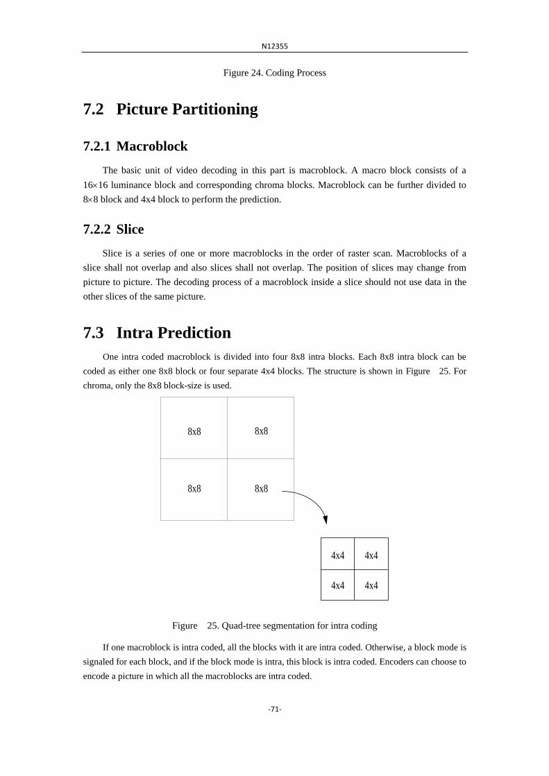
N12355
-71-
Figure 24. Coding Process
7.2 Picture Partitioning
7.2.1 Macroblock
The basic unit of video decoding in this part is macroblock. A macro block consists of a
1616 luminance block and corresponding chroma blocks. Macroblock can be further divided to
88 block and 4x4 block to perform the prediction.
7.2.2 Slice
Slice is a series of one or more macroblocks in the order of raster scan. Macroblocks of a
slice shall not overlap and also slices shall not overlap. The position of slices may change from
picture to picture. The decoding process of a macroblock inside a slice should not use data in the
other slices of the same picture.
7.3 Intra Prediction
One intra coded macroblock is divided into four 8x8 intra blocks. Each 8x8 intra block can be
coded as either one 8x8 block or four separate 4x4 blocks. The structure is shown in Figure 25. For
chroma, only the 8x8 block-size is used.
8x8
8x88x8
4x4
4x44x4
4x4
8x8
Figure 25. Quad-tree segmentation for intra coding
If one macroblock is intra coded, all the blocks with it are intra coded. Otherwise, a block mode is
signaled for each block, and if the block mode is intra, this block is intra coded. Encoders can choose to
encode a picture in which all the macroblocks are intra coded.
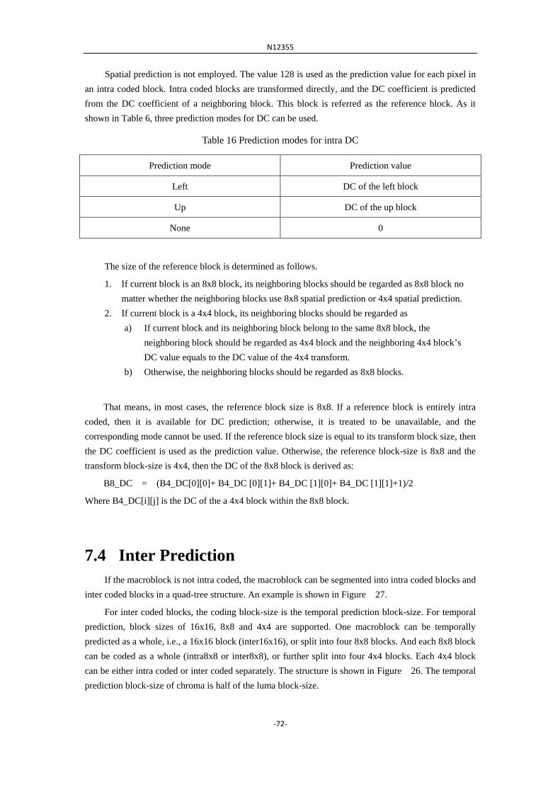
N12355
-72-
Spatial prediction is not employed. The value 128 is used as the prediction value for each pixel in
an intra coded block. Intra coded blocks are transformed directly, and the DC coefficient is predicted
from the DC coefficient of a neighboring block. This block is referred as the reference block. As it
shown in Table 6, three prediction modes for DC can be used.
Table 16 Prediction modes for intra DC
Prediction mode Prediction value
Left DC of the left block
Up DC of the up block
None 0
The size of the reference block is determined as follows.
1. If current block is an 8x8 block, its neighboring blocks should be regarded as 8x8 block no
matter whether the neighboring blocks use 8x8 spatial prediction or 4x4 spatial prediction.
2. If current block is a 4x4 block, its neighboring blocks should be regarded as
a) If current block and its neighboring block belong to the same 8x8 block, the
neighboring block should be regarded as 4x4 block and the neighboring 4x4 block‟s
DC value equals to the DC value of the 4x4 transform.
b) Otherwise, the neighboring blocks should be regarded as 8x8 blocks.
That means, in most cases, the reference block size is 8x8. If a reference block is entirely intra
coded, then it is available for DC prediction; otherwise, it is treated to be unavailable, and the
corresponding mode cannot be used. If the reference block size is equal to its transform block size, then
the DC coefficient is used as the prediction value. Otherwise, the reference block-size is 8x8 and the
transform block-size is 4x4, then the DC of the 8x8 block is derived as:
B8_DC = (B4_DC[0][0]+ B4_DC [0][1]+ B4_DC [1][0]+ B4_DC [1][1]+1)/2
Where B4_DC[i][j] is the DC of the a 4x4 block within the 8x8 block.
7.4 Inter Prediction
If the macroblock is not intra coded, the macroblock can be segmented into intra coded blocks and
inter coded blocks in a quad-tree structure. An example is shown in Figure 27.
For inter coded blocks, the coding block-size is the temporal prediction block-size. For temporal
prediction, block sizes of 16x16, 8x8 and 4x4 are supported. One macroblock can be temporally
predicted as a whole, i.e., a 16x16 block (inter16x16), or split into four 8x8 blocks. And each 8x8 block
can be coded as a whole (intra8x8 or inter8x8), or further split into four 4x4 blocks. Each 4x4 block
can be either intra coded or inter coded separately. The structure is shown in Figure 26. The temporal
prediction block-size of chroma is half of the luma block-size.

N12355
-73-
8x8 Intra
8x8 Inter8x8 Inter
4x4
Intra
4x4
Inter
4x4
Inter
4x4
Intra
Figure 26. An example of the quad-tree segmentation
8x8
8x88x8
4x4
4x44x4
4x4
8x8
16x16
Figure 27. Quad-tree segmentation for inter prediction
7.4.1 Motion vector prediction
While coding an MV, a predicted MV (MVP) is first generated, and the differential (MVD) is coded.
If the left neighboring block of the current block is available, and an MV with the same direction
(forward or backward) is used for the left block, this MV is used as the MVP of current MV.
Otherwise, 0 is used as the MVP.

N12355
-74-
7.4.2 Skip Mode
One bit is signaled for each macroblock, indicating if it is skipped. A skipped macroblock should be
derived as follows.
The coding block-size should be 16x16. If the left block exists and is not intra coded, the block mode
should be equal to the mode of the left block. Otherwise, if the picture type is P, the block mode should
be forward; if the picture type is B, it should be bi-directional. The MVD equals to 0. The residue block
is an all-zero block.
7.5 Transform
IVC supports 4x4 and 8x8 transforms. Discrete Cosine Transform (DCT) is used for the separable
two-dimensional transform. There are no scale factors for coefficients since the transform is
orthonormal. Low complexity butterfly structure for 4-point and 8-point transforms is used. Moreover,
the design of the transform is fully recursive.
7.5.1 1-D 4-point forward transform
The butterfly structure of 4x4 1-D DCT is given as below, with “x” as input and “X” as output.
+
+
+
+-
-
+
+
+
+
×
×
××
A
A
B
X0
X2
X1
X3
>>1
>>1
>>1
>>1
x0
x1
x2
x3
The irrational numbers of the parameters in the butterfly structure are approximated with rational
numbers as follows.
128167832
12869832
/)/sin(
/)/cos(
B
A
7.5.2 1-D 8-point forward transform
The butterfly structure of 8x8 1-D DCT is given as below, with “x” as input and “X” as output.

N12355
-75-
+
+
+
+
+
+
+
+
x0
x1
x2
x3
x4
x5
x6
x7
+
+
+
+
+
+
+
+-
-
-
-
×
×
××
×
×
×
×
C
C
E
EF
F
D
+
+
+
+
×
×
××
A
A
B
+
+
+
+
-
-
G
G
G
G
X0
X4
X2
X6
X1
X5
X3
X7
>>2
>>2
>>2
>>2
>>2
>>2
>>2
>>2
The irrational numbers of the parameters in the butterfly structure are approximated with rational
numbers as follows.
1281812
25620116
32256301
16
32
51214116
12512710
16
12
25647316
22256196
16
22
/
/)sin(,/)cos(
/)sin(,/)cos(
/)cos(,/)sin(
G
DC
FE
BA
7.6 Quantization
The QP range is from 0 to 63 and Table lists the parameters in the encoder side. The
quantization process is defined as follows with 16-bit precision.
inter,/)(
intra,/)(
)][_(
6210151
3110151
15
offset
offsetQPTABQCCq
Where C is the coefficient after transform and Cq the coefficient after quantization.
Table 17. The value of Q_TAB.
QP 0 1 2 3 4 5 6 7
Q_TAB 32768 29775 27554 25268 23170 21247 19369 17770
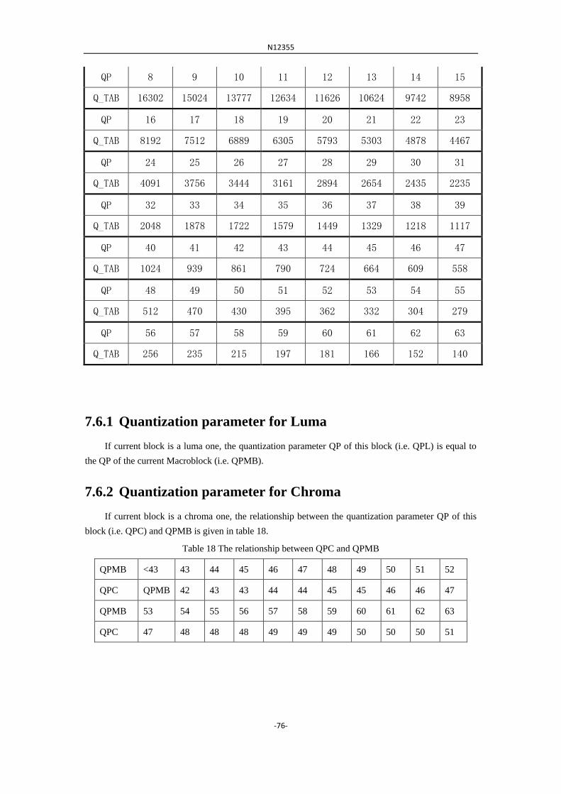
N12355
-76-
QP 8 9 10 11 12 13 14 15
Q_TAB 16302 15024 13777 12634 11626 10624 9742 8958
QP 16 17 18 19 20 21 22 23
Q_TAB 8192 7512 6889 6305 5793 5303 4878 4467
QP 24 25 26 27 28 29 30 31
Q_TAB 4091 3756 3444 3161 2894 2654 2435 2235
QP 32 33 34 35 36 37 38 39
Q_TAB 2048 1878 1722 1579 1449 1329 1218 1117
QP 40 41 42 43 44 45 46 47
Q_TAB 1024 939 861 790 724 664 609 558
QP 48 49 50 51 52 53 54 55
Q_TAB 512 470 430 395 362 332 304 279
QP 56 57 58 59 60 61 62 63
Q_TAB 256 235 215 197 181 166 152 140
7.6.1 Quantization parameter for Luma
If current block is a luma one, the quantization parameter QP of this block (i.e. QPL) is equal to
the QP of the current Macroblock (i.e. QPMB).
7.6.2 Quantization parameter for Chroma
If current block is a chroma one, the relationship between the quantization parameter QP of this
block (i.e. QPC) and QPMB is given in table 18.
Table 18 The relationship between QPC and QPMB
QPMB <43 43 44 45 46 47 48 49 50 51 52
QPC QPMB 42 43 43 44 44 45 45 46 46 47
QPMB 53 54 55 56 57 58 59 60 61 62 63
QPC 47 48 48 48 49 49 49 50 50 50 51

N12355
-77-
7.7 Entropy Coding
IVC employs a QM Coder, which is the same as Annex D of the JPEG standard (ISO/IEC
10918-3). For coefficients coding, the coefficients are coded in a zigzag order. An eobflag is coded at
the beginning of a block, and after each coefficient, to indicate if there are more coefficients after it.
7.7.1 Binarization and Context model Selection (CS)
Signed Unary code, Truncated Unary code, Fixed Length code, Signed Exp-Golomb code and
flag are used for the binarization. The binarization of all the syntax elements is given in Table 19.
Table 19 Binarization of syntax elements.
Syntax elements Binarization CS
macroblockSkipFlag flag 1context model
mbQPDelta Signed Unary code Sec. 7.7.1.1
blockSize flag 1 context model
mbSpatialTemporalDirection Fixed Length code (2-bin) 1context model for
each bin
mvDiffX Signed Zero-order Exp-Golomb
code
Sec. 7.7.1.2
mvDiffY Signed Zero-order Exp-Golomb
code
Sec. 7.7.1.2
chromaIntraMode Truncated Unary code (1 or
2-bin)
1context model for
each bin
subBlockSize flag 1context model
lumaIntraMode Truncated Unary code (1 or
2-bin)
1context model for
each bin
subMBSpatialTemporalPredictionDire
ction Fixed Length code (2-bin)
1context model for
each bin
blockSpatialTemporalPredictionDirect
ion Fixed Length code (2-bin)
1context model for
each bin
eobFlag flag Sec. 7.7.1.3
transCoefficient Signed Zero-order Exp-Golomb
code
Sec. 7.7.1.4
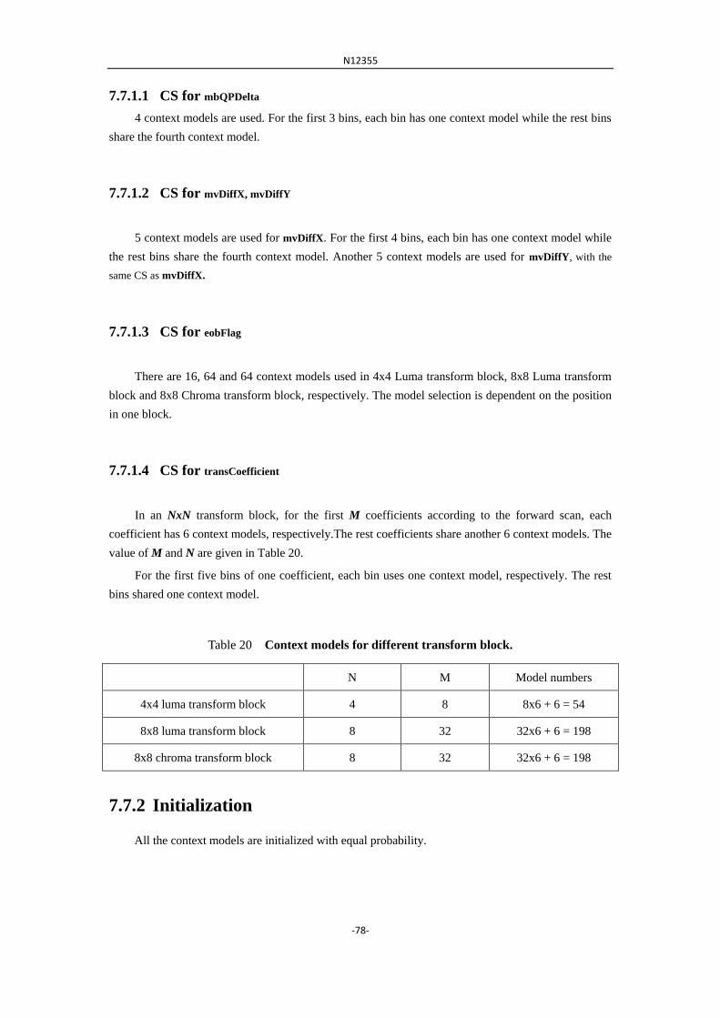
N12355
-78-
7.7.1.1 CS for mbQPDelta
4 context models are used. For the first 3 bins, each bin has one context model while the rest bins
share the fourth context model.
7.7.1.2 CS for mvDiffX, mvDiffY
5 context models are used for mvDiffX. For the first 4 bins, each bin has one context model while
the rest bins share the fourth context model. Another 5 context models are used for mvDiffY, with the
same CS as mvDiffX.
7.7.1.3 CS for eobFlag
There are 16, 64 and 64 context models used in 4x4 Luma transform block, 8x8 Luma transform
block and 8x8 Chroma transform block, respectively. The model selection is dependent on the position
in one block.
7.7.1.4 CS for transCoefficient
In an NxN transform block, for the first M coefficients according to the forward scan, each
coefficient has 6 context models, respectively.The rest coefficients share another 6 context models. The
value of M and N are given in Table 20.
For the first five bins of one coefficient, each bin uses one context model, respectively. The rest
bins shared one context model.
Table 20 Context models for different transform block.
N M Model numbers
4x4 luma transform block 4 8 8x6 + 6 = 54
8x8 luma transform block 8 32 32x6 + 6 = 198
8x8 chroma transform block 8 32 32x6 + 6 = 198
7.7.2 Initialization
All the context models are initialized with equal probability.

N12355
-79-
7.8 Encoder configurations
7.8.1 Constraint set 1 configuration
For satisfying constraint set 1, structural delay of processing units is restricted to be no larger than
8-picture "group of pictures (GOPs)" and random access intervals is restricted to be 1.1 seconds or less.
The encoder is configured as follows:
IBBP coding structure
Random access intervals is restricted to be 1.1 seconds or less.
Fixed QP assignment: QP for I, QP+2 for P, QP+5 for B
1 forward reference picture & 1 backward reference picture
RD Optimization enabled
Fast motion estimation (UMHexagon Search)
RDOQ ensabled
7.8.2 Constraint set 2 configuration
For satisfying constraint set 2, no picture reordering is allowed between decoder processing and
output, with bit rate fluctuation characteristics and no multi-pass encoding. The encoder is configured
as follows:
IPPP coding structure
Fixed QP assignment: QP for I, QP+2 for P
1 forward reference picture
RD Optimization enabled
Fast motion estimation (UMHexagon Search)
RDOQ enabled
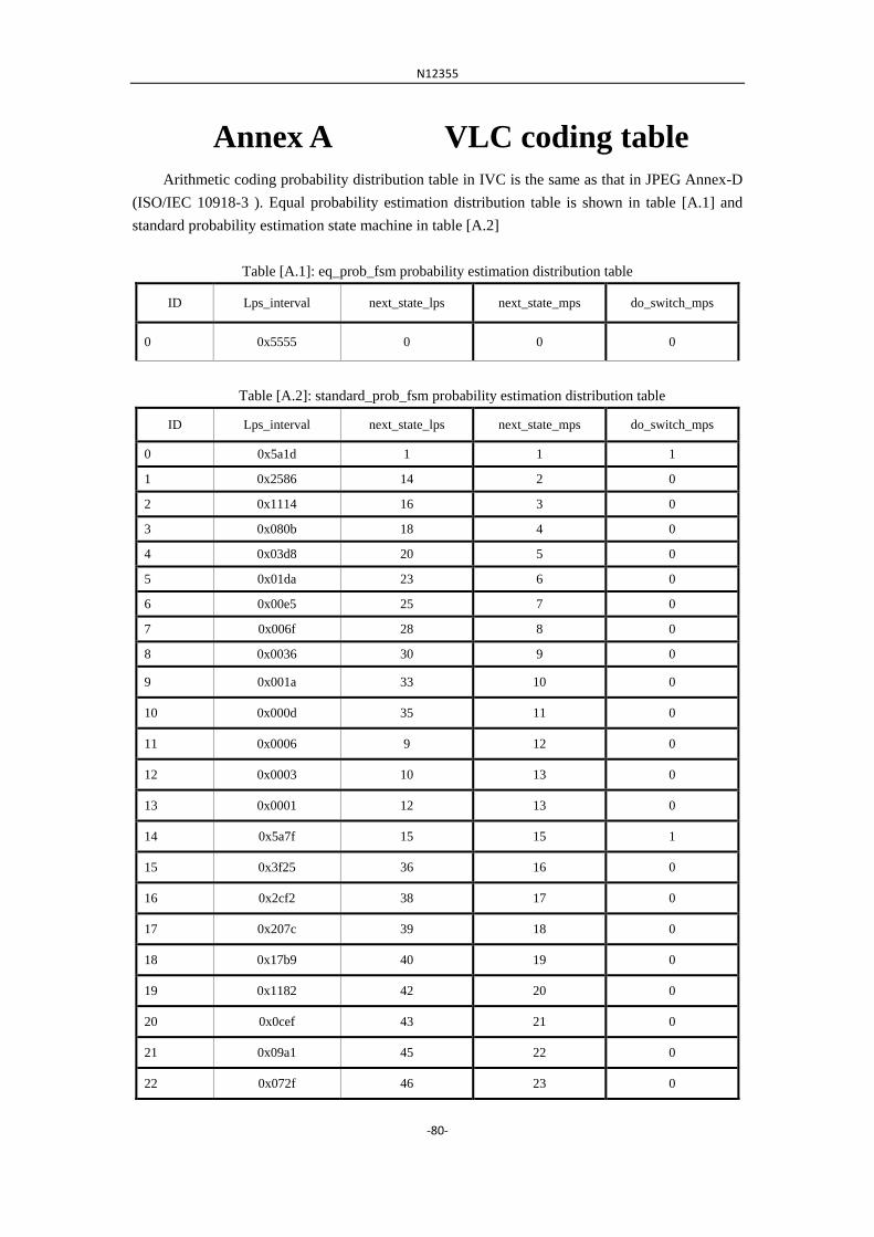
N12355
-80-
Annex A VLC coding table
Arithmetic coding probability distribution table in IVC is the same as that in JPEG Annex-D
(ISO/IEC 10918-3 ). Equal probability estimation distribution table is shown in table [A.1] and
standard probability estimation state machine in table [A.2]
Table [A.1]: eq_prob_fsm probability estimation distribution table
ID Lps_interval next_state_lps next_state_mps do_switch_mps
0 0x5555 0 0 0
Table [A.2]: standard_prob_fsm probability estimation distribution table
ID Lps_interval next_state_lps next_state_mps do_switch_mps
0 0x5a1d 1 1 1
1 0x2586 14 2 0
2 0x1114 16 3 0
3 0x080b 18 4 0
4 0x03d8 20 5 0
5 0x01da 23 6 0
6 0x00e5 25 7 0
7 0x006f 28 8 0
8 0x0036 30 9 0
9 0x001a 33 10 0
10 0x000d 35 11 0
11 0x0006 9 12 0
12 0x0003 10 13 0
13 0x0001 12 13 0
14 0x5a7f 15 15 1
15 0x3f25 36 16 0
16 0x2cf2 38 17 0
17 0x207c 39 18 0
18 0x17b9 40 19 0
19 0x1182 42 20 0
20 0x0cef 43 21 0
21 0x09a1 45 22 0
22 0x072f 46 23 0

N12355
-81-
23 0x055c 48 24 0
24 0x0406 49 25 0
25 0x0303 51 26 0
26 0x0240 52 27 0
27 0x01b1 54 28 0
28 0x0144 56 29 0
29 0x00f5 57 30 0
30 0x00b7 59 31 0
31 0x008a 60 32 0
32 0x0068 62 33 0
33 0x004e 63 34 0
34 0x003b 32 35 0
35 0x002c 33 9 0
36 0x5ae1 37 37 1
37 0x484c 64 38 0
38 0x3a0d 65 39 0
39 0x2ef1 67 40 0
40 0x261f 68 41 0
41 0x1f33 69 42 0
42 0x19a8 70 43 0
43 0x1518 72 44 0
44 0x1177 73 45 0
45 0x0e74 74 46 0
46 0x0bfb 75 47 0
47 0x09f8 77 48 0
48 0x0861 78 49 0
49 0x0706 79 50 0
50 0x05cd 48 51 0
51 0x04de 50 52 0
52 0x040f 50 53 0
53 0x0363 51 54 0
54 0x02d4 52 55 0

N12355
-82-
55 0x025c 53 56 0
56 0x01f8 54 57 0
57 0x01a4 55 58 0
58 0x0160 56 59 0
59 0x0125 57 60 0
60 0x00f6 58 61 0
61 0x00cb 59 62 0
62 0x00ab 61 63 0
63 0x008f 61 32 0
64 0x5b12 65 65 1
65 0x4d04 80 66 0
66 0x412c 81 67 0
67 0x37d8 82 68 0
68 0x2fe8 83 69 0
69 0x293c 84 70 0
70 0x2379 86 71 0
71 0x1edf 87 72 0
72 0x1aa9 87 73 0
73 0x174e 72 74 0
74 0x1424 72 75 0
75 0x119c 74 76 0
76 0x0f6b 74 77 0
77 0x0d51 75 78 0
78 0x0bb6 77 79 0
79 0x0a40 77 48 0
80 0x5832 80 81 1
81 0x4d1c 86 82 0
82 0x438e 89 83 0
83 0x3bdd 90 84 0
84 0x34ee 91 85 0
85 0x2eae 92 86 0
86 0x299a 93 87 0
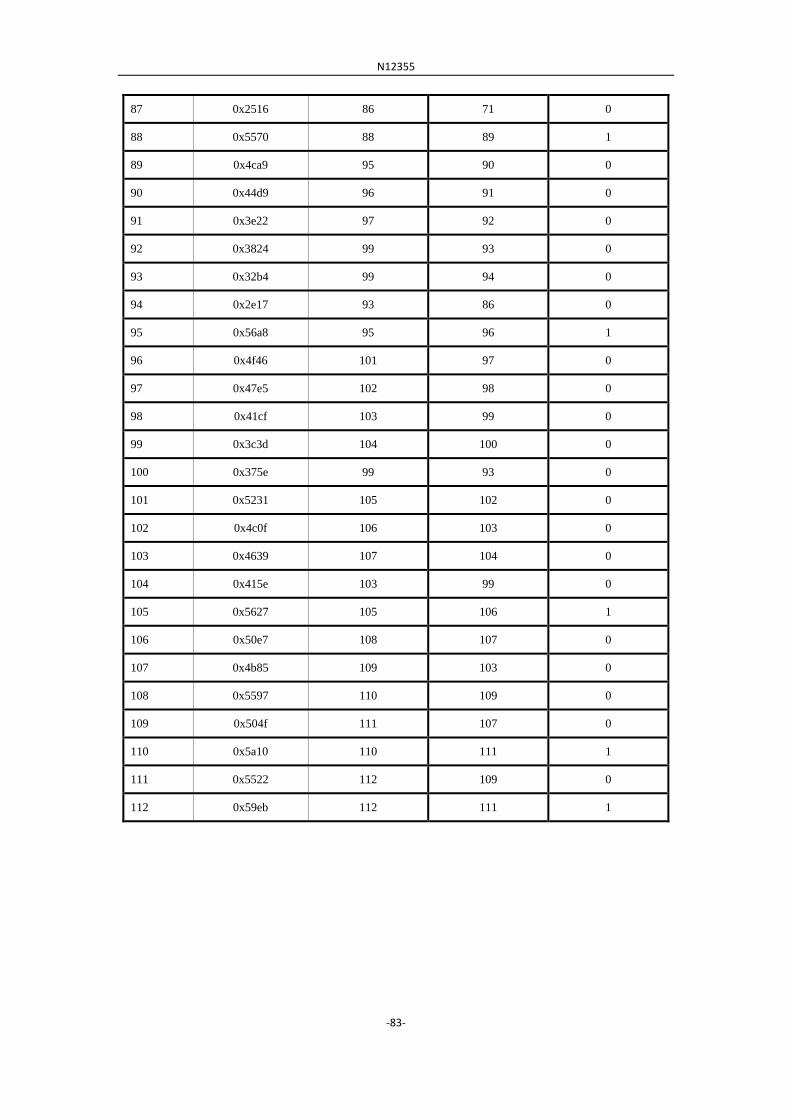
N12355
-83-
87 0x2516 86 71 0
88 0x5570 88 89 1
89 0x4ca9 95 90 0
90 0x44d9 96 91 0
91 0x3e22 97 92 0
92 0x3824 99 93 0
93 0x32b4 99 94 0
94 0x2e17 93 86 0
95 0x56a8 95 96 1
96 0x4f46 101 97 0
97 0x47e5 102 98 0
98 0x41cf 103 99 0
99 0x3c3d 104 100 0
100 0x375e 99 93 0
101 0x5231 105 102 0
102 0x4c0f 106 103 0
103 0x4639 107 104 0
104 0x415e 103 99 0
105 0x5627 105 106 1
106 0x50e7 108 107 0
107 0x4b85 109 103 0
108 0x5597 110 109 0
109 0x504f 111 107 0
110 0x5a10 110 111 1
111 0x5522 112 109 0
112 0x59eb 112 111 1
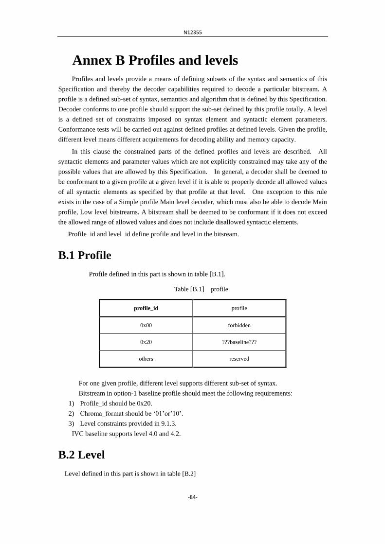
N12355
-84-
Annex B Profiles and levels
Profiles and levels provide a means of defining subsets of the syntax and semantics of this
Specification and thereby the decoder capabilities required to decode a particular bitstream. A
profile is a defined sub-set of syntax, semantics and algorithm that is defined by this Specification.
Decoder conforms to one profile should support the sub-set defined by this profile totally. A level
is a defined set of constraints imposed on syntax element and syntactic element parameters.
Conformance tests will be carried out against defined profiles at defined levels. Given the profile,
different level means different acquirements for decoding ability and memory capacity.
In this clause the constrained parts of the defined profiles and levels are described. All
syntactic elements and parameter values which are not explicitly constrained may take any of the
possible values that are allowed by this Specification. In general, a decoder shall be deemed to
be conformant to a given profile at a given level if it is able to properly decode all allowed values
of all syntactic elements as specified by that profile at that level. One exception to this rule
exists in the case of a Simple profile Main level decoder, which must also be able to decode Main
profile, Low level bitstreams. A bitstream shall be deemed to be conformant if it does not exceed
the allowed range of allowed values and does not include disallowed syntactic elements.
Profile_id and level_id define profile and level in the bitsream.
B.1 Profile
Profile defined in this part is shown in table [B.1].
Table [B.1] profile
profile_id profile
0x00 forbidden
0x20 ???baseline???
others reserved
For one given profile, different level supports different sub-set of syntax.
Bitstream in option-1 baseline profile should meet the following requirements:
1) Profile_id should be 0x20.
2) Chroma_format should be „01‟or‟10‟.
3) Level constraints provided in 9.1.3.
IVC baseline supports level 4.0 and 4.2.
B.2 Level
Level defined in this part is shown in table [B.2]

N12355
-85-
Table [B.2] Level
level_id level
0x00 forbidden
0x10 2.0
0x20 4.0
level_id level
0x22 4.2
0x40 6.0
0x42 6.2
others reserved
B.3 Level constraints independent of profiles
For all the profiles, the maximum bits constraints for one coded macroblock is shown in table
[B.3].
Table [B.3] maximum bits constraints for one coded macroblock
picture format maximum bits
4:2:0 128 + 25681.5 = 3200
4:2:2 128 + 25682 = 4224
Table [B.4], [B.5] and [B.6] give other constraints.
Table [B.4] parameter constraints in level
Parameter
level
2.0
maximum samples in a row 352
maximum rows in a frame 288
maximum frames per second 30
luma sample rate 2,534,400

N12355
-86-
maximum bit rates (bit/s) 1,000,000
BBV buffer (bits) 122,880
maximum number of macroblock per frame 396
maximum number of macroblock per second 11,880
maximum vertical motion vector confines in frame coding(luma sample numbers)
[-128, +127.75]
maximum vertical motion vector confines in field coding(luma sample numbers)
-
maximum horizontal motion vector confines (luma sample numbers)
[-2048, +2047.75]
picture format 4:2:0
Table [B.5] parameter constraints in level
parameter
level
4.0 4.2
maximum samples in a row 720 720
maximum rows in a frame 576 576
maximum frames per second 30 30
luma sample rate 10,368,000 10,368,000
maximum bit rates (bit/s) 10,000,000 15,000,000
BBV buffer (bits) 1,228,800 1,851,392
maximum number of macroblock per frame 1,620 1,620
maximum number of macroblock per second 40,500 40,500
maximum vertical motion vector confines in frame coding(luma sample numbers)
[-256, +255.75] [-256, +255.75]
maximum vertical motion vector confines in field coding(luma sample numbers)
[-128, +127.75] [-128, +127.75]
maximum horizontal motion vector confines (luma sample numbers)
[-2048, +2047.75] [-2048, +2047.75]
picture format 4:2:0 4:2:0 or 4:2:2
Table [B.6] parameter constraints in level
parameter
level
6.0 6.2

N12355
-87-
maximum samples in a row 1,920 1,920
maximum rows in a frame 1,152 1,152
maximum frames per second 60 60
luma sample rate 62,668,800 62,668,800
maximum bit rates (bit/s) 20,000,000 30,000,000
BBV buffer (bits) 2,457,600 3,686,400
maximum number of macroblock per frame 8,160 8,160
maximum number of macroblock per second 244,800 244,800
maximum vertical motion vector confines in frame coding(luma sample numbers)
[-512, +511.75] [-512, +511.75]
maximum vertical motion vector confines in field coding(luma sample numbers)
[-256, +255.75] [-256, +255.75]
maximum horizontal motion vector confines (luma sample numbers)
[-2048, +2047.75] [-2048, +2047.75]
picture format 4:2:0 4:2:0 or 4:2:2
Note: Syntactic elements relevant to table 23, 24 and 25 are horizontal_size, vertical_size, frame_rate_code
and chroma_format.


![PDF] Use empirical data benchmark criteria7) ISO 8996 (2004) Ergonomics of the thermal environment - Determination of metabolic rate. International Organisation for Standardisation,](https://img.dokumen.tips/doc/110x75/612e1b2a1ecc515869429a8d/-use-empirical-data-benchmark-criteria7-iso-8996-2004-ergonomics-of-the-thermal.jpg)