Embed Size (px)
Citation preview

1
INTERNATIONAL LASER RANGING SERVICE (ILRS)
E. C. Pavlis1, M. R. Pearlman2, C. E. Noll3, W. Gurtner4, J. Mueller5
4 Joint Center for Earth Systems Technology, UMBC and NASA GSFC, Baltimore, MD 21250, USA
2 Harvard-Smithsonian Center for Astrophysics (CfA), Cambridge, MA USA 02138, USA 3 NASA Goddard Space Flight Center, Greenbelt, MD 20771, USA
4 Astronomical Institute, University of Berne, CH-3012 Berne, Switzerland 5 University of Hannover/Institut fuer Erdmessung, Hannover, GERMANY
CONTRIBUTIONS OF THE ILRS The ILRS was organized as one of the IAG measurement services in 1998. The service collects, merges, analyzes, archives and distributes Satellite Laser Ranging (SLR) and Lunar Laser Ranging (LLR) observation data sets to satisfy the objectives of scientific, engineering, and operational applications and programs. The basic observable is the precise time-of-flight of an ultrashort laser pulse to and from a retroreflector array on a satellite. The Service also produces analogous lunar ranging observations. These data sets are used by the ILRS to generate fundamental data products, including: accurate satellite ephemerides, Earth orientation parameters, three-dimensional coordinates and velocities of the ILRS tracking stations, time-varying geocenter coordinates, static and time-varying coefficients of the Earth's gravity field, fundamental physical constants, lunar ephemerides and librations, and lunar orientation parameters. The ILRS generates a standard weekly product of station positions and Earth orientation for submission to the IERS, and produces LAGEOS combination solutions for maintenance of the International Terrestrial Reference Frame (ITRF). The ILRS participates in the Global Geodetic Observing System (GGOS) organized under the IAG. ORGANIZATION AND ROLE OF THE ILRS The ILRS accomplishes its mission through the following permanent components:
• Tracking Stations and Subnetworks • Operations Centers • Global and Regional Data Centers • Analysis and Associate Analysis Centers • Central Bureau
The ILRS Tracking Stations range to a constellation of Earth satellites, the Moon, a lunar satellite, and eventually interplanetary spacecraft with state-of-the-art laser ranging systems and transmit their data on an hourly basis to an Operations or Data Center. Stations are expected to meet ILRS data accuracy, quantity, and timeliness requirements, and their data must be regularly and continuously analyzed by at least one Analysis or mission-specific Associate Analysis Center. Each Tracking Station is typically associated with one of the three regional subnetworks: National Aeronautics and Space Administration (NASA), EUROpean LASer Network (EUROLAS), or the Western Pacific Laser Tracking Network (WPLTN). Operations Centers collect and merge the data from the tracking sites, provide initial quality checks, reformat and compress the data if necessary, maintain a local archive of the tracking data, and relay the data to a Data Center. Operational Centers may also provide the Tracking Stations with sustaining engineering, communications links, and other technical support. Tracking Stations may perform part or all of the tasks of an Operational Center themselves. Global Data Centers are the primary interfaces between the Tracking Stations and the Analysis Centers and outside users. They receive and archive ranging data and supporting information from the Operations and Regional Data Centers, and provide these data on-line to the Analysis Centers. They also receive and archive ILRS scientific data products from the Analysis Centers and provide these products on-line to users. Regional Data Centers reduce traffic on electronic networks and provide a local data archive.

2
Analysis Centers retrieve data from the archives and process them to produce the official ILRS products. They are committed to follow designated standards and produce data products on a routine basis for delivery to the Global Data Centers and the IERS. Analysis Centers routinely process the global LAGEOS-1 and LAGEOS-2 data and compute weekly solutions of station positions and Earth orientation for combination and submission to the IERS. Analysis Centers also provide a second level of data quality assurance in the network. Analysis and Associate Analysis Centers produce station coordinates and velocities, geocenter coordinates, time-varying gravity field measurements, fundamental constants, satellite predictions, precision orbits for special-purpose satellites, regional geodetic measurements, and data products of a mission-specific nature. Associate Analysis Centers are also encouraged to perform quality control functions through the direct comparison of Analysis Center products and the creation of “combined” solutions using data from other space geodetic techniques. Based on the longest observation time series of all space geodetic techniques, lunar laser ranging (LLR) analysis centers provide results for several dynamic parameters in the Earth-Moon system, e.g., orbital and libration parameters, reflector and station coordinates, and lunar physics quantities. Moreover, LLR is sensitive to nutation/precession, Earth rotation UT0, and polar motion. Also a variety of relativistic features are studied, like the strong equivalence principle, variation of the gravitational constant, metric or preferred-frame effects. CENTRAL BUREAU The ILRS Central Bureau (CB) is responsible for the daily coordination and management of ILRS activities. It facilitates communications and information transfer and promotes compliance with ILRS network standards. The CB monitors network operations and quality assurance of the data, maintains all ILRS documentation and databases, and organizes meetings and workshops. In order to strengthen the ILRS interface with the scientific community, a Science Coordinator and an Analysis Coordinator within the CB take a proactive role to enhance dialogue, to promote SLR goals and capabilities, and to educate and advise the ILRS entities on current and future science requirements related to SLR. The Science Coordinator leads efforts to ensure that ILRS data products meet the needs of the scientific community and that there is easy online access to published material relevant to SLR science and technology objectives. The CB has been actively providing new facilities to expedite communication and performance review, and adding to the technical and scientific database. The information available via the ILRS Web Site has grown enormously since its inception, and many new links to related organizations and sites have been established. The site provides details on the ILRS, the satellites and campaigns, individual SLR station characteristics, a scientific and technical bibliography on SLR and its applications, current activities of the Governing Board, Working Groups, and Central Bureau, meeting minutes and reports (including annual reports), tracking plans, and much more. The Central Bureau maintains the ILRS Web site, http://ilrs.gsfc.nasa.gov, as the primary vehicle for the distribution of information within the ILRS community. Enhancements to the ILRS Web site continue. The ILRS station information pages were expanded to include various reports and plots to monitor network performance. Station operators, analysts, and other ILRS groups can view these reports and plots to quickly ascertain how individual stations are performing as well as how the overall network is supporting the various missions. Detailed information on satellites supported by the ILRS is also available on the ILRS Web site, organized by mission. GOVERNING BOARD The Governing Board (GB) is responsible for the general direction of the service. It defines official ILRS policy and products, determines satellite-tracking priorities, develops standards and procedures, and interacts with other services and organizations. There are sixteen members of the Governing Board (GB) - three are ex-officio, seven are appointed, and six are elected by their peer groups (see Table 1). A new Board was installed in October 2008 at the 16th International Workshop on Laser Ranging in Poznan Poland. WORKING GROUPS Within the GB, permanent (Standing) or temporary (Ad-Hoc) Working Groups (WG) carry out policy formulation for the ILRS. At its creation, the ILRS established four standing WGs: (1) Missions, (2) Data Formats and Procedures, (3) Networks and Engineering, (4) Analysis, and (5) Transponders for lunar and planetary ranging. The WGs are intended to provide the expertise necessary to make technical decisions, to plan programmatic courses of action, and are responsible for reviewing and approving the content of technical and scientific databases maintained by the Central Bureau. All GB members serve on at least one of the five WGs, led by a Coordinator and Deputy Coordinator (see Table 1). The WGs continue to attracted talented people from the general ILRS membership who contributed greatly to the success of these efforts. The Missions WG, with a set of evolving formal and standardized documentation, has been working with new satellite missions to seek ILRS approval for SLR observing support, if such support is deemed necessary for the success of the mission,

3
and is within the operational capabilities of the network. The WG works with the new mission personnel and campaign sponsors to develop and finalize tracking plans and to establish recommended tracking priorities.
Table 1. ILRS Governing Board (as of June 2009)
Zuheir Altamimi Ex-Officio, President of IAG Commission France Michael Pearlman Ex-Officio, Director, ILRS Central Bureau USA Carey Noll Ex-Officio, Secretary, ILRS Central Bureau USA Bob Schutz Appointed, IERS Representative to ILRS USA Werner Gurtner Appointed, EUROLAS, Governing Board Chair Switzerland Giuseppe Bianco Appointed, EUROLAS Italy David Carter Appointed, NASA USA Jan McGarry Appointed, NASA USA Yang Fumin Appointed, WPLTN China Ramesh Govind Appointed, WPLTN Australia Vincenza Luceri Elected, Analysis Representative, Analysis Working Group Deputy Coordinator Italy Erricos C. Pavlis Elected, Analysis Representative, Analysis Working Group Coordinator USA Wolfgang Seemueller Elected, Data Centers Rep., Data Formats and Procedures WG Coordinator Germany Jürgen Mueller Elected, Lunar Representative Germany Graham Appleby Elected, At-Large, Missions Working Group Coordinator UK Georg Kirchner Elected, At-Large, Networks and Engineering Working Group Coordinator Austria
The Data Formats and Procedures WG completed the implementation of the Consolidated Prediction Format (CPF) for a much wider variety of laser ranging targets including (1) Earth-orbiting retroreflector satellites, (2) Lunar reflectors, (3) asynchronous and synchronous transponders. The new expanded format capability, with more complete modeling representation, has improved tracking on lower satellites and has removed the need for drag and special maneuver files as well as virtually all satellite time-bias corrections. The working group also designed and began implementing the Consolidated laser Ranging Data format (CRD), which accommodates full rate, sampled engineering, and normal point data types for artificial satellite, lunar, and now transponder ranging data. The format change was required to incorporate higher precision fire times for transponder ranging and to more efficiently represent full rate data from kHz laser-repetition-rate stations. The format was designed to be flexible and expandable and to incorporate additional statistical and configuration data unavailable in the earlier formats. Implementation and initial validation of the CRD format is being monitored by the WG through a cooperative effort with the OCs, DCs, and AGs (organized through the Analysis WG). The Working Group has also coordinated the implementation of new features to support mission support restrictions due to satellite vulnerability. The Networks and Engineering WG is assisting stations to upgrade to high repetition rate lasers and to implement some adaptations to the exiting normal point format to accommodate this high rate data. Software has been made available to the stations for on-site normal point data quality verification. Work continued on the bias problems with the Stanford SR620 counters, but laboratory calibrations did not prove to be sufficiently stable to reduce biases below the several cm level. The Signal Processing Study Group completed its modeling of the LAGEOS retroreflector arrays and is now working on Etalon. The Analysis WG completed its pilot projects to assess, document and resolve differences among analysis products from the Analysis and Associate Analysis Centers. Eight centers have qualified as Analysis Centers; four additional centers have expressed interest in becoming Analysis Centers, two of them already in the qualifying process. A Combination Center and a Backup Combination Center have been in operation since 2004. The WG has developed and implemented the process to deliver LAGEOS derived site positions and EOP to the IERS as required on a weekly basis. A 1983-2008 reanalysis of the LAGEOS and LAGEOS 2 data was provided to the IERS in support of the development of ITRF2008. Work is underway to add additional official ILRS products including precision orbits and certified data corrections. The Transponder Working Group has been involved in a number of activities in transponder and one-way ranging. Ground based hardware simulations for laser transponder operations at interplanetary distances have been successfully carried out within the frame of the Transponder Working Group. Results are promising and currently under review at "Planetary and Space Science". The first time transfer experiment T2L2 is under way on the satellite Jason 2. A second time transfer proposal (ELT) utilizing a laser link for the atomic clock ensemble in space (ACES) mission on the ISS has progressed to the point that it is

4
ready to be accepted for the baseline design of ACES. The transponder working group also actively supports LRO, where one-way laser ranging will improve the orbit calculations for the laser altimeter. ILRS NETWORK Satellite Laser Ranging (SLR) Network The present ILRS network includes forty stations in 23 countries (see Figure 1.) Stations designated as operational have met the minimum ILRS qualification for data quantity and quality. A dozen stations dominated the network with the Yarragadee, Mt Stromlo, Zimmerwald, and San Juan stations being the strongest performers. From start-up in 2005, the San Juan Station performance has been dramatic; in 2008 station performance has risen to second only to Yarragadee. There has also been noticeable improvement at Greenbelt, San Fernando, Concepcion, Mount Haleakala, Arequipa and Katzively. The improved orbital coverage over the Pacific region should have a very fundamental impact on our ILRS data products. The Arequipa stations and Mt Haleakala Stations were both rededicated in early 2007 with the NASA TLRS-3 and 4 SLR systems respectively; both are back in operation. In addition to San Juan, the rest of the Chinese SLR network continues its very strong support for the ILRS network. The Changchun station maintained its very strong performance, and data yield continues to improve at the new Shanghai station. The Chinese Mobile TROS system had its first session at the Korea Astronomy and Space Science Institute (KASI), Daejeon, Korea in mid-2008; the next session is scheduled for mid-2009. The Riyadh station continues to do well playing a vital role in the network as the only SLR station on the Arabian Peninsula. Data started flowing again from the Russian Stations, including the new station at Altay. The TIGO system in Concepción, Chile underwent substantial repairs in the 2005-6 time frame and is now performing very well, having reached full operational status in the network. SLR data are again flowing from the new MEO station at Grasse, France; the French Transportable Laser System (FTLRS) conducted a campaign in Burnie, Tasmania in 2008 to support altimeter calibration and validation for Jason. While there it supported the general ILRS requirements.
Figure 1. ILRS network (as of June 2009).

5
Several stations have moved to higher repetition rate lasers. In the spring of 2008, the Zimmerwald Station introduced its new 100 Hz system and rapidly became one of the major data producers in the network. The Graz system continues its impressive performance with 2 kHz operations, a technology that will most likely become more prevalent in the network as time goes on. A 2 kHz laser has been added to the Herstmonceux station; several other stations have this upgrade underway. A number of stations using the Stanford Counter have experienced timing (range) errors in some cases as large a centimeter. Calibration procedures have not been successful in addressing the problem and several of these stations have now gone to new epoch timing units – in particular the units now made by the University of Latvia. Additional stations have also moved the SPAD detectors. Lunar Laser Ranging (LLR) Network During three U.S. American Apollo missions (11, 14, and 15) and two un-manned Soviet missions (Luna 17 and Luna 21), retro-reflectors were deployed near the landing sites between 1969 and 1973 (Figure 2). The LLR experiment has continuously provided range data for about 40 years, generating about 16300 normal points. The main benefit of this space geodetic technique is the determination of a host of parameters describing lunar ephemeris, lunar physics, the Moon’s interior, various reference frames, Earth orientation parameters and the Earth-Moon dynamics. LLR has also become the strongest tool for testing Einstein's theory of general relativity in the solar system; no violations of general relativity have been found so far. However, the basis for all scientific analyses is more high quality data from a well distributed global LLR network. From all of the ILRS observatories (nearly 40), there are only a few sites that are technically equipped to carry out Lunar Laser Ranging (LLR) to retro-reflector arrays on the surface of the Moon (Figure 3). The McDonald Observatory in Texas, USA and Observatoire de la Côte d’ Azur, France are the only currently operational LLR sites. The latter has undergone renovation since late 2004, and it is expected to imminently return to action in 2009. The McDonald observatory has major problems to get further LLR tracking funded. Thus no system upgrade could be made in the past years and at the end of 2009, even any financial support for lunar tracking will be cut down, so that lunar laser ranging is not possible anymore. A new site with lunar capability has been built at the Apache Point Observatory, New Mexico, USA, equipped with a 3.5 m telescope. This station, called APOLLO, is designed for mm accuracy ranging. A new set of data from APOLLO was released in 2008 with an additional ~200 normal points, and a promise to soon make the data available in the newly adopted ILRS data format. The Australian station at Mt. Stromlo is expected to join this group in the future, and there are plans for establishing lunar capability at the South African site of Hartebeesthoek, and at Wettzell observatory, Germany, once there are new telescopes installed. Also other modern stations have demonstrated lunar capability, e.g., the Matera Laser Ranging Station, Italy in 2005, but all of them suffer from funding restrictions or technical problems when upgrading their systems. Hopefully, further sites may provide lunar data on a routine basis in the near future. Current LLR data are collected, archived and distributed under the auspices of ILRS. All former and current LLR data are electronically accessible through the EDC in Munich, Germany and the CDDIS in Greenbelt, Maryland.
Figure 2. Retro-reflector sites on the Moon, Luna 17 has never been successfully tracked.
Figure 3. ILRS sites with potential lunar capability demonstrated in the past or planned for the near future.

6
ILRS TRACKING PRIORITIES AND MISSION SUPPORT The ILRS is currently tracking 28 artificial satellites including passive geodetic (geodynamics) satellites, Earth remote sensing satellites, navigation satellites, and engineering missions (see Table 2). The stations with lunar capability are also tracking the lunar reflectors. In response to tandem missions (e.g., GRACE-A/-B) and general overlapping schedules, stations have begun tracking satellites with interleaving procedures. The ILRS assigns satellite priorities in an attempt to maximize data yield on the full satellite complex while at the same time placing greatest emphasis on the most immediate data needs. Priorities provide guidelines for the network stations, but stations may occasionally deviate from the priorities to support regional activities or national initiatives and to expand tracking coverage in regions with multiple stations. Tracking priorities are set by the Governing Board, based on application to the Central Bureau and recommendation of the Missions Working Group.
Table 2. ILRS Tracking Priorities (as of June 2009)
Satellite Priorities
Priority
Mission
Sponsor Altitude
(km) Inclination (degrees)
Comments
1 GOCE ESA 295 96.7 2 GRACE-A, -B GFZ/JPL 485-500 89 Tandem mission 3 CHAMP GFZ 429-474 87.3
4 TerraSAR-X Infoterra/DLR/ GFZ/CSR 514 97.44 First priority for acquisition phase only
5 Envisat ESA 796 98.6 Tandem with ERS-2 6 ERS-2 ESA 800 98.6 Tandem with Envisat 7 Jason-1 NASA/CNES 1,350 66.0
9 Jason-2 NASA, CNES, Eumetsat, NOAA 1,336 66.0 Tandem with Jason-1
9 Larets IPIE 691 98.2 10 Starlette CNES 815-1,100 49.8 11 Stella CNES 815 98.6 12 Ajisai NASDA 1,485 50 13 LAGEOS-2 ASI/NASA 5625 52.6 14 LAGEOS-1 NASA 5850 109.8 15 Beacon-C NASA 950-1,300 41 16 GIOVE-B ESA 23,916 56 17 Etalon-1 Russian Federation 19,100 65.3 18 Etalon-2 Russian Federation 19,100 65.2 19 COMPASS-M1 China 21,500 55.5 20 GLONASS-115 Russian Federation 19,100 65 Replaced GLONASS-99 on 03/31/2009 21 GLONASS-109 Russian Federation 19,100 65 Replaced GLONASS-95 on 05/28/2008 22 GLONASS-102 Russian Federation 19,100 65 Replaced GLONASS-89 on 05/04/2007 23 GPS-36 US DoD 20,100 55.0 24 GIOVE-A ESA 29,601 56
Lunar Priorities
Priority Retroreflector
Array
Sponsor Altitude
(km)
1 Apollo 15 NASA 356,400 2 Apollo 11 NASA 356,400 3 Apollo 14 NASA 356,400 4 Luna 21 Russian Federation 356,400
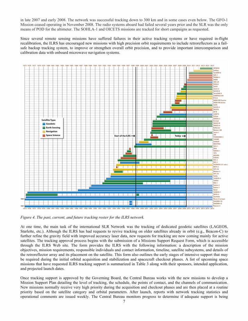
Missions are added to the ILRS tracking roster as new satellites are launched and as new requirements are adopted. Missions for completed programs are deleted from the ILRS (see Figure 4). New missions added during this reporting period included: ETS-8, GIOVE-B, Jason -2 (with T2L2); COMPASS-M1, SOHLA-1, TerraSAR-X and GOCE. The network continued to support the GLONASS program: GLONASS 102 replaced GLONASS 89 in May 2007. GLONASS 109 replaced GLONASS 95 in March 2008, and GLONASS 115 replaced GLONASS 99 in April 2009. ETS-8 was the first ILRS target in synchronous orbit. In April the GPS receiver on Jason-1 failed and SLR became the primary means of POD. The ANDE satellites reentered
7
in late 2007 and early 2008. The network was successful tracking down to 300 km and in some cases even below. The GFO-1 Mission ceased operating in November 2008. The radio systems aboard had failed several years prior and the SLR was the only means of POD for the altimeter. The SOHLA-1 and OICETS missions are tracked for short campaigns as requested. Since several remote sensing missions have suffered failures in their active tracking systems or have required in-flight recalibration, the ILRS has encouraged new missions with high precision orbit requirements to include retroreflectors as a fail-safe backup tracking system, to improve or strengthen overall orbit precision, and to provide important intercomparison and calibration data with onboard microwave navigation systems.
Figure 4. The past, current, and future tracking roster for the ILRS network. At one time, the main task of the international SLR Network was the tracking of dedicated geodetic satellites (LAGEOS, Starlette, etc.). Although the ILRS has had requests to revive tracking on older satellites already in orbit (e.g., Beacon-C) to further refine the gravity field with improved accuracy laser data, new requests for tracking are now coming mainly for active satellites. The tracking approval process begins with the submission of a Missions Support Request Form, which is accessible through the ILRS Web site. The form provides the ILRS with the following information: a description of the mission objectives, mission requirements, responsible individuals and contact information, timeline, satellite subsystems, and details of the retroreflector array and its placement on the satellite. This form also outlines the early stages of intensive support that may be required during the initial orbital acquisition and stabilization and spacecraft checkout phases. A list of upcoming space missions that have requested ILRS tracking support is summarized in Table 3 along with their sponsors, intended application, and projected launch dates. Once tracking support is approved by the Governing Board, the Central Bureau works with the new missions to develop a Mission Support Plan detailing the level of tracking, the schedule, the points of contact, and the channels of communication. New missions normally receive very high priority during the acquisition and checkout phases and are then placed at a routine priority based on the satellite category and orbital parameters. After launch, reports with network tracking statistics and operational comments are issued weekly. The Central Bureau monitors progress to determine if adequate support is being

8
provided. New mission sponsors (users) are requested to report at the ILRS meetings on the status of ongoing campaigns, including the responsiveness of the ILRS to their needs and on progress towards achieving the desired science or engineering results.
One interesting application for SLR is the tracking support of the Lunar Reconnaissance Orbiter (LRO), launched June 17, 2009. The LRO mission objective is to conduct investigations that will be specifically targeted to prepare for and support future human exploration of the Moon. The LRO Laser Ranging (LR) system will use one-way range measurements from laser ranging stations on the Earth to LRO to determine LRO position at sub-meter level with respect to Earth and the center of the Moon (on the lunar near-side or whenever possible). The LR aspect of the mission will allow for the determination of a more precise orbit than possible with S-band tracking data alone. The flight system consists of a receiver telescope, which captures the uplinked laser signal and a fiber optic cable, which routes it to the LOLA instrument. The LOLA instrument captures the arrival time of the laser signal, records that information and provides it to the onboard LRO data system for storage and/or transmittal to the ground through the RF link.
Table 3. Upcoming Missions (as of June 2009)
Mission Sponsor Planned Launch
Date
Mission Duration (years)
Altitude (km)
Inclination (degrees) Application
ANDE NRL Jul-2009 1-3 350 51.6° Atmospheric modeling BLITS IPIE Aug-2009 5 832 98.77° Test of retroreflector technology
PROBA-2 ESA Dec-2009 2 721 98° Technology validation QZS-1 JAXA 2010 12 32K-40K 45°
STSAT-1 KAIST Mid-2009 390-1500 80° Technology development and Earth brightness
TanDEM-X DLR, GFZ,
EADS, Astrium, InfoTerra
Mid-2009 5 514 97.44° Digital elevation models
NPOESS NOAA, NASA, DoD 2013 7 833 98.7° Sea surface height
OFFICIAL ANALYSIS PRODUCTS The ILRS products consist of SINEX files of weekly station coordinates and daily Earth Orientation Parameters (x-pole, y-pole and excess length-of-day, LOD) estimated from 7-day arcs. Two types of products are distributed each week: a loosely constrained estimation of coordinates and EOP and an EOP solution, derived from the previous one and constrained to an ITRF, currently ITRF2000. Official ILRS Analysis Centers (AC) and Combination Centers (CC) generate these products with individual and combined solutions respectively. Both the individual and combined solutions follow strict standards agreed upon within the ILRS Analysis Working Group (AWG) to provide high quality products consistent with the IERS Conventions 2003. This description refers to the status as of January 2009. Each official weekly ILRS solution is obtained through the combination of weekly solutions submitted by the official ILRS Analysis Centers:
ASI, Agenzia Spaziale Italiana BKG, Bundesamt für Kartographie und Geodäsie DGFI, Deutsches Geodätisches Forschungsinstitut GA, Geosciences Australia GFZ, GeoForschungsZentrum Potsdam GRGS, Observatoire de Cote d’ Azur JCET, Joint Center for Earth Systems Technology NSGF, NERC Space Geodesy Facility
These ACs have been certified through benchmark tests developed by the AWG. The official Primary Combination Center (ASI) and the official Backup Combination Center (DGFI) follow strict timelines for these routinely provided products. In addition to operational products, solutions have been provided covering the period back to 1983. A current effort is underway to provide similar solutions on a daily basis, with a minimal 2-day delay, primarily to provide IERS’ NEOS center with robust EOP observations for their weekly forecasting. The ILRS products are available, via ftp from the official ILRS Data Centers CDDIS/NASA Goddard (ftp://cddis.gsfc.nasa.gov/) and EDC/DGFI (ftp://ftp.dgfi.badw-muenchen.de).

9
ILRS Contribution to ITRF2008 The time series of weekly solutions from 1983 to the end of 2008, produced by the Primary Combination Center, was delivered to IERS/ITRS as an official ILRS contributed data set for ITRF2008. Several months of joint work within the ILRS AWG were devoted to the quality assessment of the contributing solutions from the ILRS ACs as well as the final combined solutions from the ILRS CCs. The preliminary version of the combined ILRS time series was submitted in April 2009. Figures 5 and 6 show the origin and scale differences with respect to the old ITRF realization, ITRF2005 (actually the SLRF2005 frame, a derivative of ITRF2005, scaled for compliance to the SLR scale and merged with the ITRF2000 normal equations to cover all sites tracking between early 80’s to present, These time series are essentially equivalent to the ones that have been generated operationally since after January 2007 and only differ from that in the applied tropospheric model (Marini-Murray for the old vs. Mendes-Pavlis for the new series) and the modeling of a range biases for a subset of stations. The latter have been the focus of extensive studies and comparisons with engineering tests and logs. After these extensive investigations it became apparent that even for the best sites some of the biases are best determined by analysis rather than engineering tests, and that was the route adopted for the establishment of a database with definite biases for all sites with known bias problems during specified periods. The entire bias database will be made public on the ILRS web pages and it will be maintained in the future for the benefit of all SLR data users. The description of the official contribution to ITRF2008 will be made available on the ILRS pages once the new model is finalized and adopted by ITRS.
Figure 5. Origin offsets of the weekly product with respect to SLRF2005 (ITRF2005S): 1983-2009.

10
Figure 6. Scale difference of the weekly product with respect to SLRF2005 (ITRF2005S): 1983–2009.
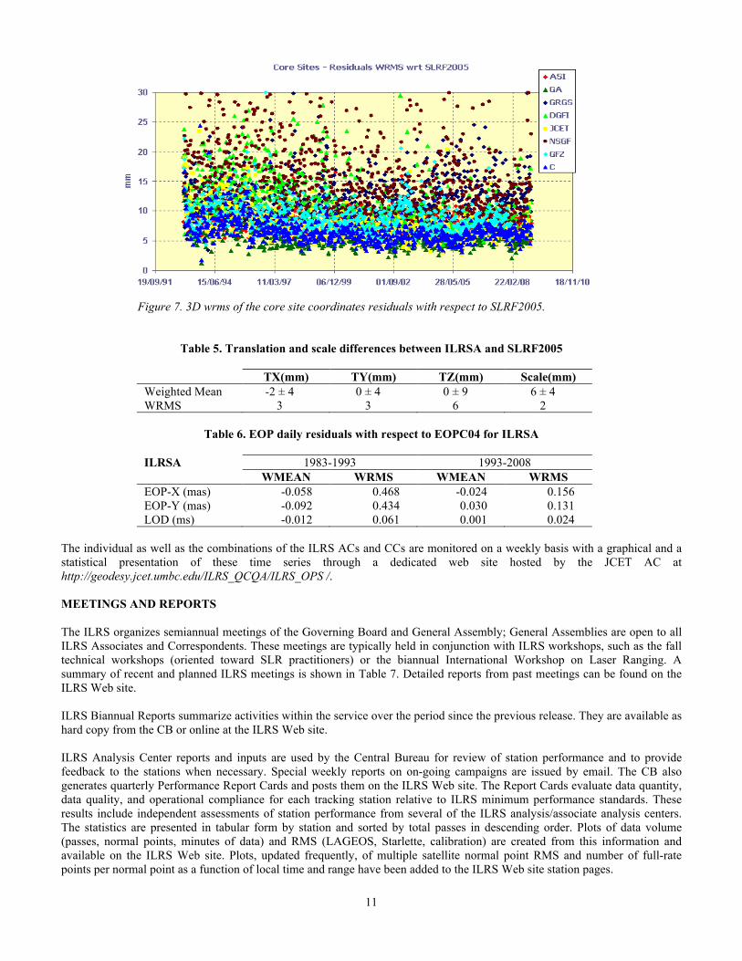
The official ILRS Combination (ILRS-A) ASI produces the official ILRSA combination solution and it is routinely compared with the backup combined solution ILRSB produced by DGFI following a fundamentally different approach. Comparisons show a good agreement between the two solutions and absence of any systematic differences.
1. mean 3D wrms of the site coordinates residuals with respect to SLRF2005 (Table 4 and Figure 7); 2. mean differences of the translation and scale parameters with respect to SLRF2005 (Table 5); 3. EOP residuals with respect to EOP 05 C04 (Table 6) for the year 2008.
Table 4. 3D wrms of the site coordinates residuals w.r.t. SLRF2005
ILRSA(mm)
1983-1993 1993-2008 All sites (mean) 52 10 Core sites (mean) 15 7
11
Figure 7. 3D wrms of the core site coordinates residuals with respect to SLRF2005.
Table 5. Translation and scale differences between ILRSA and SLRF2005
TX(mm) TY(mm) TZ(mm) Scale(mm) Weighted Mean -2 ± 4 0 ± 4 0 ± 9 6 ± 4 WRMS 3 3 6 2
Table 6. EOP daily residuals with respect to EOPC04 for ILRSA
ILRSA 1983-1993 1993-2008 WMEAN WRMS WMEAN WRMS EOP-X (mas) -0.058 0.468 -0.024 0.156 EOP-Y (mas) -0.092 0.434 0.030 0.131 LOD (ms) -0.012 0.061 0.001 0.024
The individual as well as the combinations of the ILRS ACs and CCs are monitored on a weekly basis with a graphical and a statistical presentation of these time series through a dedicated web site hosted by the JCET AC at http://geodesy.jcet.umbc.edu/ILRS_QCQA/ILRS_OPS /. MEETINGS AND REPORTS The ILRS organizes semiannual meetings of the Governing Board and General Assembly; General Assemblies are open to all ILRS Associates and Correspondents. These meetings are typically held in conjunction with ILRS workshops, such as the fall technical workshops (oriented toward SLR practitioners) or the biannual International Workshop on Laser Ranging. A summary of recent and planned ILRS meetings is shown in Table 7. Detailed reports from past meetings can be found on the ILRS Web site. ILRS Biannual Reports summarize activities within the service over the period since the previous release. They are available as hard copy from the CB or online at the ILRS Web site. ILRS Analysis Center reports and inputs are used by the Central Bureau for review of station performance and to provide feedback to the stations when necessary. Special weekly reports on on-going campaigns are issued by email. The CB also generates quarterly Performance Report Cards and posts them on the ILRS Web site. The Report Cards evaluate data quantity, data quality, and operational compliance for each tracking station relative to ILRS minimum performance standards. These results include independent assessments of station performance from several of the ILRS analysis/associate analysis centers. The statistics are presented in tabular form by station and sorted by total passes in descending order. Plots of data volume (passes, normal points, minutes of data) and RMS (LAGEOS, Starlette, calibration) are created from this information and available on the ILRS Web site. Plots, updated frequently, of multiple satellite normal point RMS and number of full-rate points per normal point as a function of local time and range have been added to the ILRS Web site station pages.
12
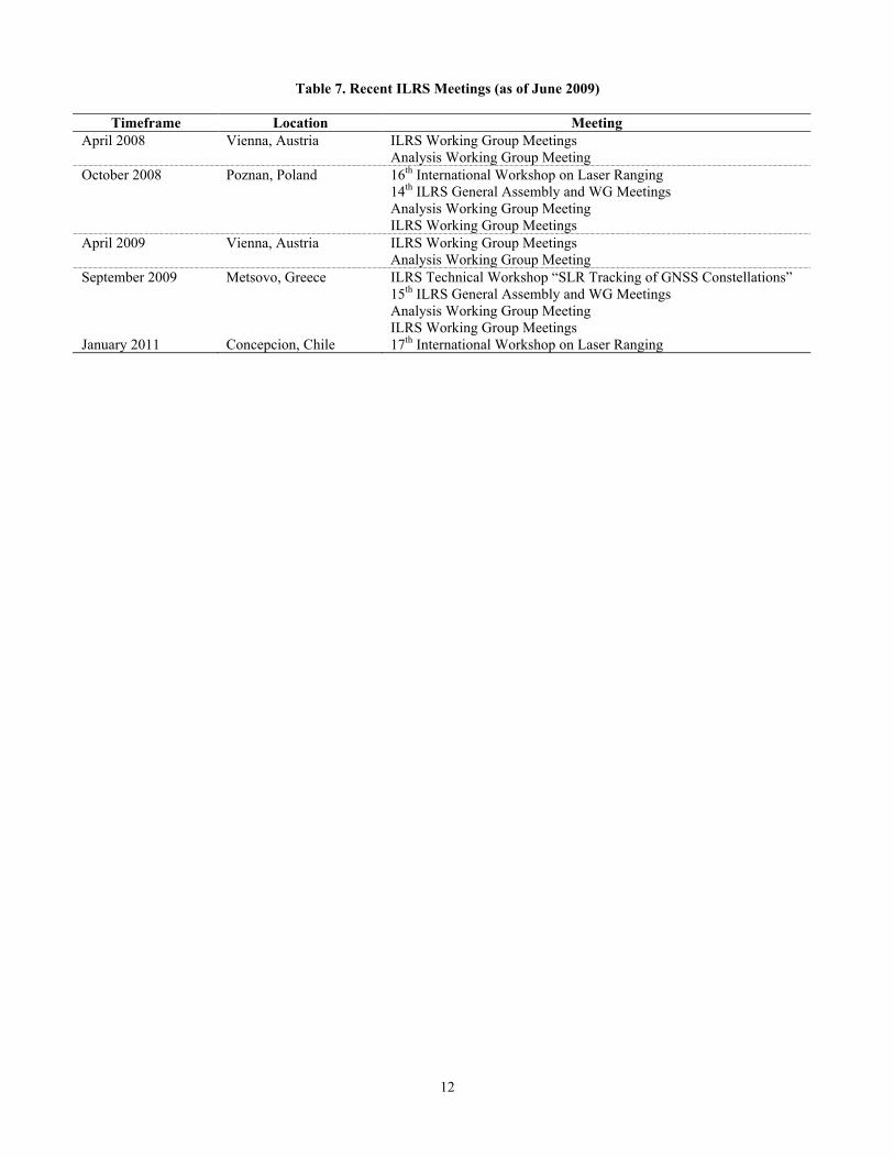
Table 7. Recent ILRS Meetings (as of June 2009)
Timeframe Location Meeting
April 2008 Vienna, Austria ILRS Working Group Meetings Analysis Working Group Meeting
October 2008 Poznan, Poland 16th International Workshop on Laser Ranging 14th ILRS General Assembly and WG Meetings Analysis Working Group Meeting ILRS Working Group Meetings
April 2009 Vienna, Austria ILRS Working Group Meetings Analysis Working Group Meeting
September 2009 Metsovo, Greece ILRS Technical Workshop “SLR Tracking of GNSS Constellations” 15th ILRS General Assembly and WG Meetings Analysis Working Group Meeting ILRS Working Group Meetings
January 2011 Concepcion, Chile 17th International Workshop on Laser Ranging


![Monitoring the Time Bias in laser ranging stations thanks ......Network accurate at 1 mm and stable at 1 mm/y [Plag et al. 2009] ILRS Recommendations Laser Ranging stations synchronized](https://img.dokumen.tips/doc/110x75/5f49d91b929e26056e10cc0c/monitoring-the-time-bias-in-laser-ranging-stations-thanks-network-accurate.jpg)