Embed Size (px)
Citation preview
Review Article ISSN: 2319-507X
Nichat AV, IJPRET, 2013; Volume 1(8):336-347 IJPRET
Available Online At www.ijpret.com
INTERNATIONAL JOURNAL OF PURE AND
APPLIED RESEARCH IN ENGINEERING AND
TECHNOLOGY A PATH FOR HORIZING YOUR INNOVATIVE WORK
APPLICATION OF REVERSE ENGINEERING USING CMM FOR MANUFACTURING
INTRICATE COMPONENT: A CASE STUDY
A. V. NICHAT1, N. W. KALE
2, Dr. A. U. AWATE
2, M. R. DHARME
1
1. Department of Mechanical Engineering, IBSS College of Engineering, University-Mardi
Road Amravati.
2. Department of Mechanical Engineering, Prof. Ram Meghe Institute of Technology &
research, Badnera Amravati.
Accepted Date:
27/02/2013
Publish Date:
01/04/2013
Keywords
Splineshaft, Gearbox,
CMM (Coordinate
Measuring Machine),
Reverse Engineering,
Point Cloud Data (PCD),
CAD Modeling And
Analysis,
NC Part programming,
CAM.
Corresponding Author
Mr. A. V. Nichat
Abstract
The aim of this study is to redesign a physical product which has been
already manufactured. It is based on an integrated use of Point Cloud
Data (PCD) achieved from 3D scans of model from Coordinate
Measuring Machine (CMM). This method was found to be simpler and
it assists in producing more accurate intricate component and thus
more accurate CAD models in the reverse engineering of same parts. In
order to obtain CAD model of the component to be applied in the
supports design and measurement path, the Reverse Engineering
which is the only technique allowing to copy faithfully and to
reconstruct complex geometric entities. In this paper an attempt has
been made to find out the dimensions of pre-existing splineshaft of
gearbox using reverse engineering. Splineshaft is an essential
component which establishes a power transmitting between the
various gear assembly of gearbox. The geometric data of undertaken
component has been obtained by using CMM. The 3D model of
splineshaft has been created by using CATIA. The analysis of splineshaft
has been performed at various loads ranging from minimum value to
maximum value in order to study the behavior of splineshaft by using
ANSYS. And the finally for computer aided manufacturing NC part
programming is generated by using CATIA
Review Article ISSN: 2319-507X
Nichat AV, IJPRET, 2013; Volume 1(8):336-347 IJPRET
Available Online At www.ijpret.com
INTRODUCTION
Engineering fields are constantly improving
upon designs and methods to make life
simple and easier. When referring to
technology, simple and easier can be
directly related to fast and accurate.
Engineering is described as "the application
of scientific and mathematical principles to
practical ends such as the design,
manufacture, and operation of efficient and
economical structures, machines,
processes, and systems". This type of
engineering is more commonly known as
Forward Engineering. An emerging
engineering concept is utilizing forward
engineering in a reverse way. This method
is more commonly referred to as Reverse
Engineering.
Reverse engineering is the opposite of
forward engineering. It takes an existing
product, and creates a CAD model, for
modification or reproduction to the design
aspect of the product. It can also be defined
as the process or duplicating an existing
component by capturing the components
physical dimensions.
2. LITERATURE REVIEW
Bardell et al. (2003):- defined reverse
engineering as systematic evaluation of a
product with the purpose of replication
which involves either direct copies or
adding improvements to existing design.
They have also proposed a method of
automating the verification of an
acceptable free-form surface, using
coordinate measuring machine (CMM).
Computer-aided geometric design (CAGD) is
used to analyze the surface for optimum
continuity and assess the CMM data
accuracy.
Mohammad Shadab et. al. (2006):-
presented the applications of the reverse
engineering method on the modeling of
Pillion step holder of Hero Honda CBZ
Motor Bike. The CAD Model of Pillion step
holder has been developed by CATIA V5
using the cloud data. The stress analysis of
pillion step holder was also done. Results
shows that the maximum stress at critical is
within the permissible limit as compared to
the strength of the material and the
deflections in the component is much lesser
than the permissible value. Again the stress
Review Article ISSN: 2319-507X
Nichat AV, IJPRET, 2013; Volume 1(8):336-347 IJPRET
Available Online At www.ijpret.com
is performed on the modified CAD Model. It
is found that the maximum stress and
maximum deflection is still within the
permissible limit. It also helps to
understand the behavior of the CAD Model
under various loading conditions and
further help to modify it.
F. Belarifi et. al. (2008):- This paper propose
a method to optimize the module of cutting
conical spur gear, after being worn or
broken, with the aid of Computer-Aided
Design (CAD). It also allows creating a
virtual model, by theoretical geometric
characteristics, to calculate the volume. The
suggested method allows determining the
geometric features of a pair of conical spur
gear after worn. A simulation package,
R2000, was used and special "AutoCAD"
software has been developed to accomplish
the drawing of 2D wheel conical spur gear,
the verification of the system assembly and
the drawing of a 3D volume pattern.
A.R. Ismail et. al. (2009):- explained the
modeling and machining of four stroke
piston engine using Reverse engineering
method. The process include digitizing
process by using layout machine to capture
the point clouds and following by the
Computer Aided Design (CAD) stage and
Computer Aided Manufacturing (CAM)
stage using Unigraphics NX2 software to
reconstruct the piston engine surface. Then,
machining process with Computer
Numerical Control (CNC) machine is used to
create the piston head engine. Finally, the
accuracy of the replicated piston engine is
checked by using Coordinate Measurement
Machine (CMM) and block gauge.
Niranjan Singh et. al. (2012):- In this paper
the methodology of Reverse Engineering
has been employed to Brake Rod of Bajaj
Pulsar 150cc Motor Bike. This paper
describes the generation of 2D model of
Brake Rod using photogrammetry
technique, development of 3D solid model
on SolidWorks and Autodesk Inventor,
stresses are analysed at different loads.
Finally the results of SolidWorks have been
compared with the results of Autodesk
Inventor. [1]
To avoid the wastage of time if possible the
manufacturing information is obtained itself
from the manufacturer. In order to reverse
engineer a product or a component of a
Review Article ISSN: 2319-507X
Nichat AV, IJPRET, 2013; Volume 1(8):336-347 IJPRET
Available Online At www.ijpret.com
system, engineers & researchers generally
follow the following four stage process:-
• Identifying the product or component to
be reverse engineered.
• Observing or disassembling the
information documenting how the
original product works.
• Implementing the technical data
generated by reverse engineering in
replica or modified version of the
original.
• Creating the new product.
In the first stage in the process, sometimes
called "prescreening," reverse engineers
determine the candidate product for their
project. Potential candidates for such a
project include singular items, parts,
components, units, subassemblies, some of
which may contain many smaller parts sold
as a single entity.
The second stage, disassembly of the
original product, is the most time-
consuming aspect of the project. In this
stage, reverse engineers attempt to
construct a characterization of the system
by accumulating all of the technical data
and how the product works.
In the third stage of reverse engineering,
reverse engineers try to verify that the data
generated by disassembly is an accurate
reconstruction the original system.
Engineers verify the accuracy and validity of
their designs by testing the system,
creating prototypes, and experimenting
with the results.
The final stage of the reverse engineering
process is the introduction of a new product
into the marketplace. These new products
are often innovations of the original
product with competitive designs, features,
or capabilities. These products may also be
adaptations of the original products for use
with other integrated systems such as
different platforms of computer operating
systems.
3. INVESTIGATIONS OF EXISTING
SPLINESHAFT:
Splineshaft is an essential structure element
which provides linkage between gear
assembly of gearbox. Its one end is engage
with small spur gear and other end is
Review Article
Nichat AV, IJPRET, 2013; Volume 1(8):336
Available Online At www.ijpret.com
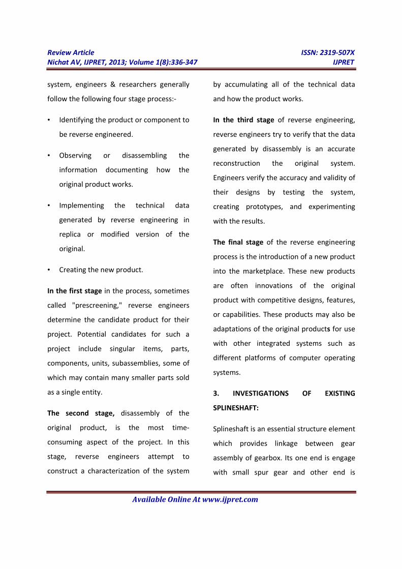
attached to large spur gear assembly. In this
part the investigations of the existing
splineshaft have been carried out.
Figure 2. Splineshaft of gearbox and its
various parameter
3.1. Measurement of various Lengths,
major and minor Diameters:
The various dimensions of splineshaft were
measured by using CMM. The different
readings obtained are shown in table given
below:
4. METHODOLOGY
Article
IJPRET, 2013; Volume 1(8):336-347
Available Online At www.ijpret.com
attached to large spur gear assembly. In this
part the investigations of the existing
haft have been carried out.
of gearbox and its
3.1. Measurement of various Lengths,
major and minor Diameters:
The various dimensions of splineshaft were
measured by using CMM. The different
readings obtained are shown in table given
In reverse engineering, collection of
coordinates of every point of contact of
Table 1. Various parameters of splineshaft
probe with the part surface is the point
cloud data of the part/product.
Different steps are followed in this
technique are:-
• Scan by using CMM:
splineshaft coordinates are measured by
mm; 2 mm 00 degrees probe and manual
scanning are used for effective collection of
points data.
The CMM used here is the Global Classic
Sr. No. Parameters
A Diameter of Left spline
B Diameter of left collar
C Middle diameter
D Diameter of right side collar
E Diameter of bearing rest right
F Diameter of right spline
G spline length left
H spline length right
I Length left up to collar
J Length between two collar
K Length right up to bearing rest
L overall length
M bearing rest length right
a Fillet at left side
b Fillet at right side
ISSN: 2319-507X
IJPRET
In reverse engineering, collection of
coordinates of every point of contact of
Table 1. Various parameters of splineshaft
probe with the part surface is the point
cloud data of the part/product.
Different steps are followed in this
• Scan by using CMM: - In this technique,
splineshaft coordinates are measured by 30
mm; 2 mm 00 degrees probe and manual
scanning are used for effective collection of
The CMM used here is the Global Classic-SR.
Dimensions
Diameter of Left spline 34.37mm
41.42mm
38.00mm
Diameter of right side collar 48.00mm
Diameter of bearing rest right 40.00mm
right spline 34.37mm
47.00mm
37.00mm
Length left up to collar 54.00mm
Length between two collar 114.75mm
Length right up to bearing rest 41.00mm
231.75mm
bearing rest length right 20.00mm
50.00mm
30.00mm
Review Article
Nichat AV, IJPRET, 2013; Volume 1(8):336
Available Online At www.ijpret.com
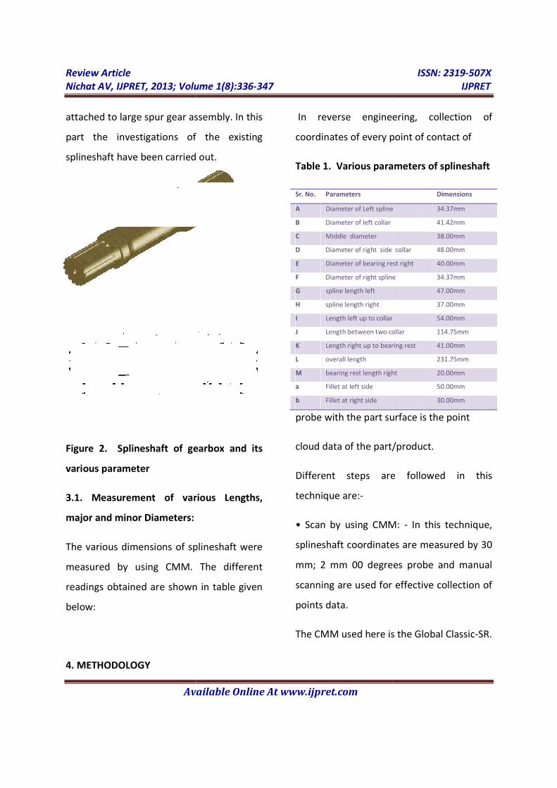
Figure 3. Coordinate Measuring Machine
Global Classic-SR is the most cost effective
solution to common shop measurement
and inspection applications. Available in
configurations to support either touch
trigger or analog scanning probes, Classic is
ideal as a first CMM, for mult
deployments, or as a cost-effective way to
add extra automated inspection capacity to
your quality program.
Standard Package contain in Global Classic:
Probe: TESASTAR-I manual indexing probe
head
Software: PC-DMIS-2011
Control: UMP360 touch trigger controller
Accessories: Computer package, desk,
installation.
Article
IJPRET, 2013; Volume 1(8):336-347
Available Online At www.ijpret.com
Measuring Machine
SR is the most cost effective
solution to common shop measurement
and inspection applications. Available in
configurations to support either touch
trigger or analog scanning probes, Classic is
ideal as a first CMM, for multiple-unit
effective way to
add extra automated inspection capacity to
Standard Package contain in Global Classic:
I manual indexing probe
gger controller
Accessories: Computer package, desk,
Options: Upgraded controller, probes and
software
The data conversion depends on software
availability in the CMM. Some of the CMM
software converts the data into CAD
format, like DXF, DWG
forms. It has a PC-DMIS PRO software pack
for converting the data into polyline IGES
format as small segments depending on
pitch. The polylines are then converted into
curves/splines and this will reduce the
curve generating process.
By using this technique we get PCD which is
then imported in CAD software.
• After importing data in CAD software 2D
CAD Model is created by using drawing
commands.
• The CAD Model is then scaled accordingly
with one exactly known dimension. Then all
other dimensions are automatically
extracted from the CAD Model.
• Finally the 3D CAD Model is created using
CATIA software.
5. CAD Modeling of Splineshaft
ISSN: 2319-507X
IJPRET
Options: Upgraded controller, probes and
The data conversion depends on software
availability in the CMM. Some of the CMM
software converts the data into CAD
format, like DXF, DWG, STL, IGES, and other
DMIS PRO software pack
for converting the data into polyline IGES
format as small segments depending on
pitch. The polylines are then converted into
curves/splines and this will reduce the
curve generating process.
By using this technique we get PCD which is
then imported in CAD software.
• After importing data in CAD software 2D
CAD Model is created by using drawing
• The CAD Model is then scaled accordingly
with one exactly known dimension. Then all
her dimensions are automatically
extracted from the CAD Model.
• Finally the 3D CAD Model is created using
5. CAD Modeling of Splineshaft
Review Article ISSN: 2319-507X
Nichat AV, IJPRET, 2013; Volume 1(8):336-347 IJPRET
Available Online At www.ijpret.com
The software used here for modeling is
CATIA. It is CAD/CAE/CAM integration
software of French Dassault Systems, which
can provides users an integrated digital
environment and complexity requirements
for users from design to manufacture. [4]
Following steps are required for the
development of CAD Model of Splineshaft
with the help of available solid modeling
technique:-
• Importing PCD in CAD software.
• Scaling accordingly with one exactly
known dimension (length of splineshaft) i.e.
231.75mm.
• Creating the features by CATIA.
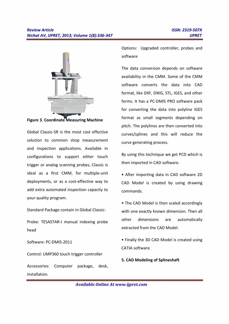
The first step in reverse engineering process
is to import the scanned data, which is in
the form of lines, arc, circles etc. in CAD
package (CATIA).
Figure 4. Point Cloud Data of Splineshaft
imported in CATIA
Above figure shows imported PCD in CATIA,
now by using drawing commands all lines,
arc, circles are converted into 2D CAD
Model.
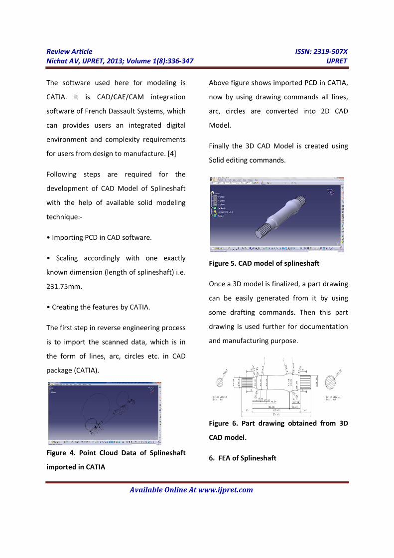
Finally the 3D CAD Model is created using
Solid editing commands.
Figure 5. CAD model of splineshaft
Once a 3D model is finalized, a part drawing
can be easily generated from it by using
some drafting commands. Then this part
drawing is used further for documentation
and manufacturing purpose.
Figure 6. Part drawing obtained from 3D
CAD model.
6. FEA of Splineshaft
Review Article ISSN: 2319-507X
Nichat AV, IJPRET, 2013; Volume 1(8):336-347 IJPRET
Available Online At www.ijpret.com
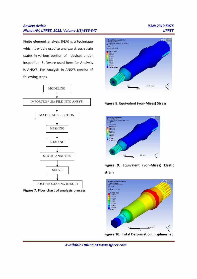
Finite element analysis (FEA) is a technique
which is widely used to analyze stress-strain
states in various portion of devices under
inspection. Software used here for Analysis
is ANSYS. For Analysis in ANSYS consist of
following steps
Figure 7. Flow chart of analysis process
Figure 8. Equivalent (von-Mises) Stress
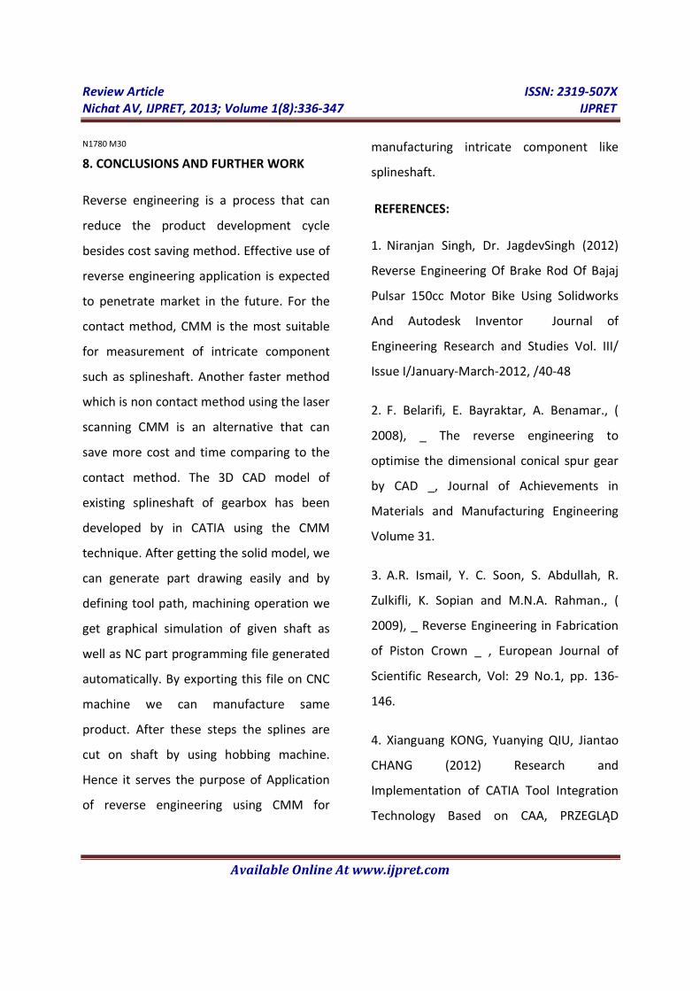
Figure 9. Equivalent (von-Mises) Elastic
strain
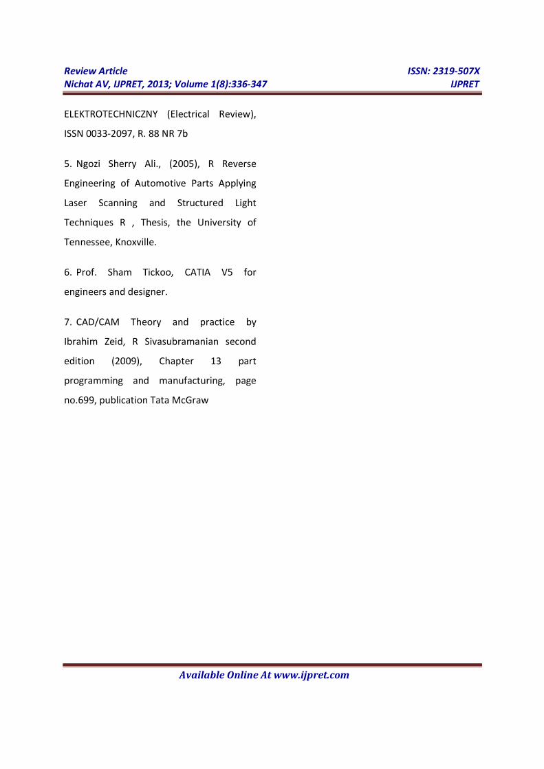
Figure 10. Total Deformation in splineshat
IMPORTED * .Sat FILE INTO ANSYS
MODELING
LOADING
MESHING
MATERIAL SELECTION
STATIC ANALYSIS
SOLVE
POST PROCESSING-RESULT

Review Article ISSN: 2319-507X
Nichat AV, IJPRET, 2013; Volume 1(8):336-347 IJPRET
Available Online At www.ijpret.com
Various analyses done on given splineshaft
shown in above Figures. Following table
shows behaviour of splineshaft after
applying various boundary conditions and
twisting load on it.
7. CAM of Splineshaft
The CATIA software has provides a 2.5-axis,
3 axis and multi-axis CNC machining
modules. Users can compile NC
programming using CATIA, both can call a
tool from CATIA tool library, and can
manually enter the parameters to create
the CATIA has powerful CNC machining
modules. The basic operation methods of
CNC machining include setting processing
elements, setting the tool path, setting tool
parameters, setting feed/back knife, cutting
simulation and generating NC programs.
Selecting tool is very important in the NC
content, for each machining operation
needs to specify a processing tool. [4]
Following steps are required for the
development of CAM of Splineshaft with
the help of available software technique:-
• Create raw material shaft used for
manufacturing the given product.
• Used lathe machining from advance
machining tool available in software.
• Define tool used, tool path, tool angle
etc.
Table 2. Tabulated Results for splineshaft
• Simulate of machining operation.
• Defining machine used for
manufacturing.
• Finally, we get output file which is
generated automatically in the machine
readable format generally in NC coding
which used G- Preparatory and M-
miscellaneous code. By exporting this
file on CNC machine we can
manufacture same product.
Minimum Maximum
Load (N) 0 2000
Equivalent (Von-mises)
stress in mpa
0.088875 163.28
Equivalent (Von-mises)
elastic strain
4.4438e-7
0.00081642
Total Deformation (max)
mm
00 0.06534

Review Article ISSN: 2319-507X
Nichat AV, IJPRET, 2013; Volume 1(8):336-347 IJPRET
Available Online At www.ijpret.com
In this case study the tool path define is
shown with red lines in given below figure
Figure 11. Defining tool path.
Following figure shows the tool used and
tool positioning for machining a part
Figure 12. Tool used and its positioning
Figure 13. Simulation of machining
operation
Figure above shows the Simulation of
machining operation before going for actual
manufacturing of product.
Here, we are defining post processor and
emulator as a Cenit® and machine post
processor as a Sinumerik 840D. Finally, an
output extension file as NC code will be
generated automatically in the machine
readable format generally in NC coding
which used G- Preparatory and M-
miscellaneous code. The NC coding format
generated during this operation is given
below
;==========================================
;= cPost Standard PP for SINUMERIK 840 D =
;==========================================
N10 G0 G90 G40
N20; ============= TOOL CHANGE ============
N30; DESC:
N40;=======================================
N50 T1 M06
N60 D1
N70 G0 G90 G40 G17
N80 F0 S0
N90 G64 SOFT
N100 G0 X37.791 Y0 Z233.889 S70 M4
N110 G0 X27.791
N120 G1 X25.791 F0 G95
.
.
.
N1740 X17.925 Z3.89
N1750 X13.234 Z-6.171
N1760 X13.336 Z-6.453 F1
N1770 M5 M9
Review Article ISSN: 2319-507X
Nichat AV, IJPRET, 2013; Volume 1(8):336-347 IJPRET
Available Online At www.ijpret.com
N1780 M30
8. CONCLUSIONS AND FURTHER WORK
Reverse engineering is a process that can
reduce the product development cycle
besides cost saving method. Effective use of
reverse engineering application is expected
to penetrate market in the future. For the
contact method, CMM is the most suitable
for measurement of intricate component
such as splineshaft. Another faster method
which is non contact method using the laser
scanning CMM is an alternative that can
save more cost and time comparing to the
contact method. The 3D CAD model of
existing splineshaft of gearbox has been
developed by in CATIA using the CMM
technique. After getting the solid model, we
can generate part drawing easily and by
defining tool path, machining operation we
get graphical simulation of given shaft as
well as NC part programming file generated
automatically. By exporting this file on CNC
machine we can manufacture same
product. After these steps the splines are
cut on shaft by using hobbing machine.
Hence it serves the purpose of Application
of reverse engineering using CMM for
manufacturing intricate component like
splineshaft.
REFERENCES:
1. Niranjan Singh, Dr. JagdevSingh (2012)
Reverse Engineering Of Brake Rod Of Bajaj
Pulsar 150cc Motor Bike Using Solidworks
And Autodesk Inventor Journal of
Engineering Research and Studies Vol. III/
Issue I/January-March-2012, /40-48
2. F. Belarifi, E. Bayraktar, A. Benamar., (
2008), _ The reverse engineering to
optimise the dimensional conical spur gear
by CAD _, Journal of Achievements in
Materials and Manufacturing Engineering
Volume 31.
3. A.R. Ismail, Y. C. Soon, S. Abdullah, R.
Zulkifli, K. Sopian and M.N.A. Rahman., (
2009), _ Reverse Engineering in Fabrication
of Piston Crown _ , European Journal of
Scientific Research, Vol: 29 No.1, pp. 136-
146.
4. Xianguang KONG, Yuanying QIU, Jiantao
CHANG (2012) Research and
Implementation of CATIA Tool Integration
Technology Based on CAA, PRZEGLĄD
Review Article ISSN: 2319-507X
Nichat AV, IJPRET, 2013; Volume 1(8):336-347 IJPRET
Available Online At www.ijpret.com
ELEKTROTECHNICZNY (Electrical Review),
ISSN 0033-2097, R. 88 NR 7b
5. Ngozi Sherry Ali., (2005), R Reverse
Engineering of Automotive Parts Applying
Laser Scanning and Structured Light
Techniques R , Thesis, the University of
Tennessee, Knoxville.
6. Prof. Sham Tickoo, CATIA V5 for
engineers and designer.
7. CAD/CAM Theory and practice by
Ibrahim Zeid, R Sivasubramanian second
edition (2009), Chapter 13 part
programming and manufacturing, page
no.699, publication Tata McGraw