Embed Size (px)
Citation preview

lable at ScienceDirect
International Journal of Pressure Vessels and Piping 88 (2011) 198e212
Contents lists avai
International Journal of Pressure Vessels and Piping
journal homepage: www.elsevier .com/locate/ i jpvp
Design of pressure vessels using shape optimization: An integrated approach
R.C. Carbonari a, P.A. Muñoz-Rojas b, E.Q. Andrade c, G.H. Paulino d,e, K. Nishimoto f, E.C.N. Silva a,*
aDepartment of Mechatronic Engineering, Escola Politécnica da Universidade de São Paulo, Av. Prof. Mello Moraes, 2231 São Paulo, SP 05508-900, BrazilbDepartment of Mechanical Engineering, Universidade do Estado de Santa Catarina, Bom Retiro, Joinville, SC 89223-100, BrazilcCENPES, PDP/Métodos Científicos, Petrobras, BrazildNewmark Laboratory, Department of Civil and Environmental Engineering, University of Illinois at Urbana-Champaign, 205 North Mathews Av., Urbana, IL 61801, USAeDepartment of Mechanical Science and Engineering, University of Illinois at Urbana-Champaign, 158 Mechanical Engineering Building, 1206 West Green Street, Urbana,IL 61801-2906, USAfDepartment of Naval Architecture and Ocean Engineering, Escola Politécnica da Universidade de São Paulo, Av. Prof. Mello Moraes, 2231 São Paulo, SP 05508-900, Brazil
a r t i c l e i n f o
Article history:Received 7 September 2010Received in revised form10 May 2011Accepted 11 May 2011
Keywords:Shape optimizationPressure vesselMulti-objective function
* Corresponding author. Tel.: þ55 11 30919754; faxE-mail addresses: [email protected] (R.C. Carbonari),
Muñoz-Rojas), [email protected] (E.Q.(G.H. Paulino), [email protected] (K. Nishimoto), ecn
0308-0161/$ e see front matter � 2011 Elsevier Ltd.doi:10.1016/j.ijpvp.2011.05.005
a b s t r a c t
Previous papers related to the optimization of pressure vessels have considered the optimization of thenozzle independently from the dished end. This approach generates problems such as thickness variationfrom nozzle to dished end (coupling cylindrical region) and, as a consequence, it reduces the optimalityof the final result which may also be influenced by the boundary conditions. Thus, this work discussesshape optimization of axisymmetric pressure vessels considering an integrated approach in which theentire pressure vessel model is used in conjunctionwith a multi-objective function that aims to minimizethe von-Mises mechanical stress from nozzle to head. Representative examples are examined andsolutions obtained for the entire vessel considering temperature and pressure loading. It is noteworthythat different shapes from the usual ones are obtained. Even though such different shapes may not beprofitable considering present manufacturing processes, they may be competitive for futuremanufacturing technologies, and contribute to a better understanding of the actual influence of shape inthe behavior of pressure vessels.
� 2011 Elsevier Ltd. All rights reserved.
1. Introduction
In the pressure vessel literature, the optimization of nozzle andheads has been conducted independently. Although this is a prac-tical and widely used approach, it leads to undesirable problemssuch as thickness variation from nozzle to head (among others)and, as a consequence, reduces the optimality of the final result(which may also be influenced by the adopted boundary condi-tions). Thus, this work investigates the optimization of pressurevessels considering a model of the entire vessel. A multi-objectivefunction based on a p-root of summation of p-exponent terms ofvon-Mises stress values is defined in order to minimize the tankmaximum von-Mises stresses. Mechanical and thermal loads areconsidered. Shape optimization techniques are applied, and thedesign optimization procedure is implemented by combining thecommercial finite element analysis system ANSYS with our MAT-LAB optimization algorithm. Although composite tanks have
: þ55 11 [email protected] (P.A.Andrade), [email protected]@usp.br (E.C.N. Silva).
All rights reserved.
a strength/weight ratio higher than steel tanks, they have a highermanufacturing cost. Thus, this work emphasizes homogeneoustanks, and focuses on CNG (Compressed Natural Gas) tank designby means of shape optimization techniques.
This paper is organized as follows. The literature review andrelated work are presented in Section 2. The formulation andnumerical implementation of the optimization problem for thepressure vessel is described in Sections 3 and 4, respectively. InSection 5, the optimized shapes for the entire pressure vessel arepresented and the results are discussed. Finally, in Section 6, someconclusions are inferred.
2. Related work
The design of pressure vessels is an important and practicaltopic which has been explored for decades. Even though optimi-zation techniques have been extensively applied to design struc-tures in general, few pieces of work can be found which are directlyrelated to optimal pressure vessel design. These few references aremainly related to the design optimization of homogeneous andcomposite pressure vessels.
A pioneering work on optimization techniques for designingpressure vessels was presented by Middletown and Owen [1], who

x
yy1
spline Shy2
ynh
x1x2
xnn
} head variables
}nozzle variables
spline Sn
Fig. 1. Definition of design variables.
y
x
nodes
integration points
topbottom
midsurface
Fig. 3. Details of the shell element (employed in this work).
R.C. Carbonari et al. / International Journal of Pressure Vessels and Piping 88 (2011) 198e212 199
used parametric optimization techniques to minimize the maxi-mum shear stress in the design of a pressure vessel dished end(head) modeled with axisymmetric finite elements. Following thiswork, Middletown [2] applied these parametric optimizationtechniques to design a pressure vessel nozzle considering theminimization of the maximum shear stress. Mechanical andthermal loads were taken into account by specifying differenttemperatures in the internal and external walls of the nozzle anddished end (head). Later, Blachut [3] also applied parametric opti-mization techniques to minimize the weight of the dished end byconsidering the limit pressure instead of mechanical stress. Thelimit pressurewas defined as the value that first causes a full plasticregion along the entire thickness of the pressure vessel. The opti-mization problem was defined as the minimization withconstraints of the limit pressure, the strain at the peak of the dishedend, and box constraints for parametric design variables. A zeroorder method (no gradients) was applied to solve the optimizationproblem. Four situations were studied: optimization of the main
Initialization and
Data Input
Creation of Spline Curve
and
Solution of FEM
Calculation of Objective Function and Constraints
Converged?
Calculate Sensitivities and Moving Limits
Solve LP problem with
respect to xi
and yi
Update xi
and yi
ENDY
N
Fig. 2. Flowchart of optimization procedure.
dimensions of a torispherical shell; optimization of the ellipticalprofile of the torispherical shell with uniform thickness; the sameproblem, but including the thickness as a design variable; and againthe same problem, however, considering the thickness varyingalong the meridian defined by a polynomial. The weight reductionobtained was 8%, 19%, 27%, and 31%, respectively. As an importantconclusion, they showed that the boundary conditions between thedished end and the cylinder do influence the design. A “Fully StressedDesign”-(FSD), which keeps the stress constant along the body, wasalso performed, however, it produced inferior results in relation tothe best result among the four cases discussed, showing that, asexpected, the design considering stress constraints is not as intui-tive and thus a more formal approach is needed.
Another relevant work considering pressure vessel design usingcomputational modeling was presented by Zhu and Boyle [4], whoapplied shape optimization techniques to optimize separately thehead and nozzle of the pressure vessel, considering as objectivefunction either the mechanical stresses or the limit pressure. Thelimit pressure is calculated by using the elastic compensationmethod [5e7], and performing successive linear analyses, whichhas as main advantage the fact that it precludes the need to
P, Ti
x
y
Te
sym
met
ry
Fig. 4. Computer-aided Engineering (CAE) model including pressure (P), temperature(Ti, Te), and boundary conditions.

d0
d1
h1
h4
h3
h2
x
ysymmetry point
Fig. 5. Initial pressure vessel shape.
Table 2Initial values for design variables (mm).
initial shape 1 initial shape 2 initial shape 3 elliptical head
y1 (0; 3066) y1 (0; 3066) y1 (0; 3066) y1 (0; 2066)y2 (500; 2932) y2 (382.7; 2989.9) y2 (258.8; 3.31.9) y2 (223; 2053)y3 (866; 2566) y3 (707.1; 2773.1) y3 (500; 2932) y3 (434; 2016)x1 (900; 893) y4 (923.9; 2448.7) y4 (707.1; 2773.1) y4 (624; 1957)x2 (800; 719) x1 (900; 893) y5 (866; 2560) y5 (782; 1877)x3 (700; 546) x2 (800; 719) y6 (965.9,2324.8) y6 (901; 1783)x4 (600; 373) x3 (700; 546) x1 (900; 893) y7 (975; 1677)
x4 (600; 373) x2 (800; 719) x1 (900; 893)x3 (700; 546) x2 (800; 719)x4 (600; 373) x3 (700; 546)
x4 (600; 373)
R.C. Carbonari et al. / International Journal of Pressure Vessels and Piping 88 (2011) 198e212200
perform non-linear analysis, thus reducing the computational costin the overall optimization procedure. Their optimization proce-dure was implemented using the software ANSYS with the APDL(ANSYS Parametric Design Language) language and spline curves toperform shape optimization. The obtained results showed satis-factory improvements. The work of Malinowski and Magnuki [8]employed parametric discrete optimization techniques to designinternal reinforcements of pressure vessels by minimizing thereinforcement mass considering stress constraints. Following ananalytical approach, Banichuk et al. [9] used variational calculus tofind the head meridian profile optimal curve in order to maximizethe ratio between head volume and mass subjected to stressconstraints.
An interesting issue when designing the head (or nozzle) is thestress concentration in the transition between the head (or nozzle)and the cylinder. At the head and cylinder junction, bendingmoments and shear forces appear in order to compensate thestiffness difference between the components (head and cylinder).These bending moments and shear forces generate a stressconcentration that can be estimated by thin shell theory. Whena non-hemispherical head is considered, the stress concentrationalong the junction increases. Such stress concentration can bereduced either by transitioning the thickness from the head to thecylinder or by changing the head geometry. Following this idea,Magnucki and Lewinsky [10] analytically assessed the headgeometry (shape) design that generates an equivalent stress lessthan or equal to the cylinder stress. In this case, the internalbending moments and shear forces would be null. They considereda head geometry partially composed by a sphere and a genericcurve (to be determined). The sphere radius is calculated togenerate equivalent stresses in the head that do not exceed theequivalent stress at the cylinder surface. The stress is uniform and
Table 1Material properties.
Young’s Modulus E 200.0 � 109 PaPoisson’s Ratio n 0.3Density r 7810.0 Kg/m3
Thermal expansion a 1.15 � 10�5 1/◦C
the thickness is uniform for the proposed geometry. An equivalentellipsoidal head would have an equivalent stress value in the head20% larger than the equivalent stress in the cylinder and a headthickness 50% larger than the cylinder thickness. The minimizationof stress concentration in pressure vessels with ellipsoidal headswas also discussed by Magnucki et al. [11] by means of analyticaltechniques. As noticed in their previous work, if the same thicknessis considered for head and cylinder, there is a stress concentrationin the junction of head and cylinder with head stresses being largerthan cylinder stresses. A stress equalization can be obtained byincreasing the head thickness or by changing the head geometry b/a > 0.5, where b and a are the minor and major ellipse axes,respectively. In the case of thickness variation, an increase of 70%from cylinder to head would be necessary, which is impracticalfrom amanufacturing point of view. An interesting plot of thicknessratio as a function of (b/a) ratio related to the non-dimensionalequivalent stress equalization between head and cylinder couldbe built. From this plot, by considering the same thickness for headand cylinder, the ratio (b/a) must be equal to 0.6 for stress equal-ization. In another plot, the ratio between the maximum non-dimensional equivalent stress and the cylinder equivalent stress(subjected to pressure only) is given as a function of the ratio (b/a).It shows that (b/a) values less than 0.48 are not of interest becausethe stress concentration would increase. For (b/a) values rangingfrom 0.48 to 0.86, high stress values are generated (although equalfor head and cylinder). Thus, other criteria, such as minimummass,must be selected to decide on a (b/a) value between 0.48 and 0.86.From these previous pieces of work, we conclude that heads withhemispherical, torispherical or elliptical geometries are not optimalbecause they can only avoid the stress concentration in the junctionbetween head and cylinder with large thickness variation, whichmay be impractical (e.g. from a manufacturing point of view).Meanwhile, it is also concluded that the minimization of the stressconcentration in the junction can be achieved by changing the headmeridian profile shape, suggesting that shape optimization tech-niques can be applied to search for this optimum shape. The samestudy could be developed for the junction between nozzle andcylinder, however, no analytical work has been found, probably,due to difficulties to develop the analytical model. However, similarconclusions may be applied, that is, by changing the nozzlemeridian profile shape the stress concentration in the transitioncan be reduced.
Table 3Representative optimization parameters.
p 1 to 8w 0.5ah 0.25an 0.5fh ¼ fn ¼ 0.01

0 500 1000 1500 2000 2500 3000 3500 40000
50
100
150
200
250
Along length (mm)
von
Mis
es s
tres
s (M
Pa)
1402807001400
number of elements:
A EDCB
x
yA
B C
D E
Fig. 6. von-Mises stress values along vessel meridional profile, considering different discretizations and no thermal load.
R.C. Carbonari et al. / International Journal of Pressure Vessels and Piping 88 (2011) 198e212 201
Although most of previous optimization literature assumedspecific geometries, Hammer and Olhoff [12] used topology opti-mization to design structures subjected to pressure loads. For suchdesign-dependent problem, the boundary where the pressure isapplied must move as the material is removed. This problem isaddressed by using a spline function to represent the boundarywhere the pressure is applied. A follow up of this work wasprovided by Du and Olhoff [13] and Zheng et al. [14], who extendedthe investigation to three-dimensional structures. However, theyconsidered as objective function the minimization of meancompliance without stress constraints, which is not realistic forpressure vessel design. In fact, the solution of topology optimiza-tion considering stress constraints is still an open problem [15e17].
Recently, Blachut andMagnuki [18]published anextensive reviewabout modeling and optimization of pressure vessels where theymention that, in the optimization field, there are still few pieces ofwork related to pressure vessel design. This work provides a contri-bution along those lines by presenting an integrated approach inwhich the entire vessel is considered in the optimization process.
3. Formulation of the shape optimization problem
In this section, an approach to design CNG tanks based onthe shape optimization technique is presented. In this shape
0 500 1000 1500 20
100
200
300
400
500
600
Along le
von
Mis
es s
tres
s (M
Pa)
1402807001400
number of elements:
A B
Fig. 7. von-Mises stress values along vessel meridional profile
optimization approach, the head and nozzle meridian profilecurves will be optimized by using spline curves, thus no pre-defined shape will be assumed. Shape here refers to thegeometric shape of the midsurface with a uniform thickness. Theshape of the midwall surface is more important than thickness foreither maximum stress or load-carrying capacity [4]. A typicaloptimization problem is defined as
Min FðxÞSubjected to gðxÞ � 0
xL � x � xU
where F(x) is the objective function, x are the design variables, g(x)are inequality constraints, and xL and xU are box constraints. Thepressure vessel optimized design can be achieved by directenforcement of maximum stress as constraints or, alternatively, bydefining a stress measure to be minimized as objective function. Inthis work, we deal with the stress minimization problem bydefining a multi-objective function based on a p-root of summationof p-exponent terms of von-Mises stresses. These stresses are theusual choice of stress measurement for pressure vessel design inthe literature [10,11]. The von-Mises stresses are chosen instead oflimit pressure [5e7] because the intention is to design the vessel foractual working conditions [4]. If different levels of mechanicalstresses occur in nozzle and head regions in this work, then an
000 2500 3000 3500 4000ngth (mm)
x
yA
B C
D E
EDC
, considering different discretizations and thermal load.

R.C. Carbonari et al. / International Journal of Pressure Vessels and Piping 88 (2011) 198e212202
analysis of the entire vessel is performed. A proper mathematicalsetting must be formulated in the sense that the optimizationprocess should guarantee that nozzle and head stress values willhave equal influence in the objective function. This is achieved byusing a logarithmic function. Thus, a multi-objective function isdefined as the sum of the logarithmic of the p-root of summation ofp-exponent terms of head and nozzle von-Mises stresses, allowingthe control of the head and nozzle stresses through a weightingcoefficient, which it is given by:
F ¼ wln�Xnh
i¼1sphj
�1pþð1�wÞln
�Xnn
j¼1spnj
�1p (1)
where shiand snj are the von-Mises mechanical stresses at Gauss
points of the i e th and j e th finite elements that model the headand nozzle, respectively; w is the weighting coefficient whichallows control of the influence of stresses in the head and nozzleregions in the optimization problem; p is an exponent coefficientwhich can assume even or odd values (as von-Mises stress valuesare always positive); nh and nn are the number of finite elementsused to discretize the head and nozzle regions, respectively.Therefore, the minimization of the multi-objective functionconsists of minimizing simultaneously the von-Mises mechanicalstresses in the head and nozzle regions.
0 500 10000
500
1000
1500
2000
2500
3000
Dimension in x (mm)
Dim
ensi
on in
y (
mm
)
initialoptimized
head spline knots=3
0 500 1000
500
1000
1500
2000
2500
3000
Dimension in x (
Dim
ensi
on in
y (
mm
)
head spline kno
a
c
Fig. 8. Optimization result obtained for initial shapes 1, 2, and 3 corresponding to differentgiven beside each figure.
3.1. Design variables
In the adopted shape optimization approach the shapes of headand nozzle are given by cubic spline interpolation whose shape ischanged during the optimization process by varying the coordi-nates of spline knots. Separate spline curves are defined for thehead and for the nozzle. The optimization must be performed ina way that the spline knots move in the normal direction to thespline curve, because analytical shape sensitivity in the directiontangent to the spline can be shown to be null. In principle, x and ycoordinates of spline knots could be chosen as design variables,however, considering the constraint that knots must move in thenormal direction, it suffices to choose only x or y coordinates. Fig. 1shows that x and y knot coordinates are chosen as the designvariables for nozzle and head splines, respectively. Thus, the headdesign variable set is defined by the coordinates of the head splineknots (yh) in the Cartesian direction y, while the nozzle designvariable set is defined by the coordinates of the nozzle spline knots(xn) in the Cartesian x direction, as illustrated in Fig. 1.
3.2. Complexity constraints
In order to reduce the numerical oscillations during the opti-mization process, and to control the spline shape, complexity
0 500 10000
500
1000
1500
2000
2500
3000
Dimension in x (mm)
Dim
ensi
on in
y (
mm
)
initialoptimized
head spline knots=4
0mm)
initialoptimized
ts=6
b
number of head spline knots (no thermal load). Detailed views of head and nozzle are
0 500 1000 1500 2000 2500 3000 3500 40000
50
100
150
200
250
300
350
Along length (mm)
von
Mis
esst
ress
(MPa
)
optimizedinitialsemi-spherical headanalytical ( cylinder)8
A EDCB
x
yA
B C
D E
head spline knots=3
0 500 1000 1500 2000 2500 3000 3500 40000
50
100
150
200
250
300
350
head spline knots=4
0 500 1000 1500 2000 2500 3000 3500 40000
50
100
150
200
250
300
350
Along length (mm)
von
Mis
esst
ress
(MPa
)
optimizedinitialsemi-spherical head
A EDCB
x
yA
B C
D Eanalytical ( cylinder)8
head spline knots=6
a
b
c
Along length (mm)
von
Mis
esst
ress
(MPa
)
optimizedinitialsemi-spherical head
A EDCB
x
yA
B C
D Eanalytical ( cylinder)8
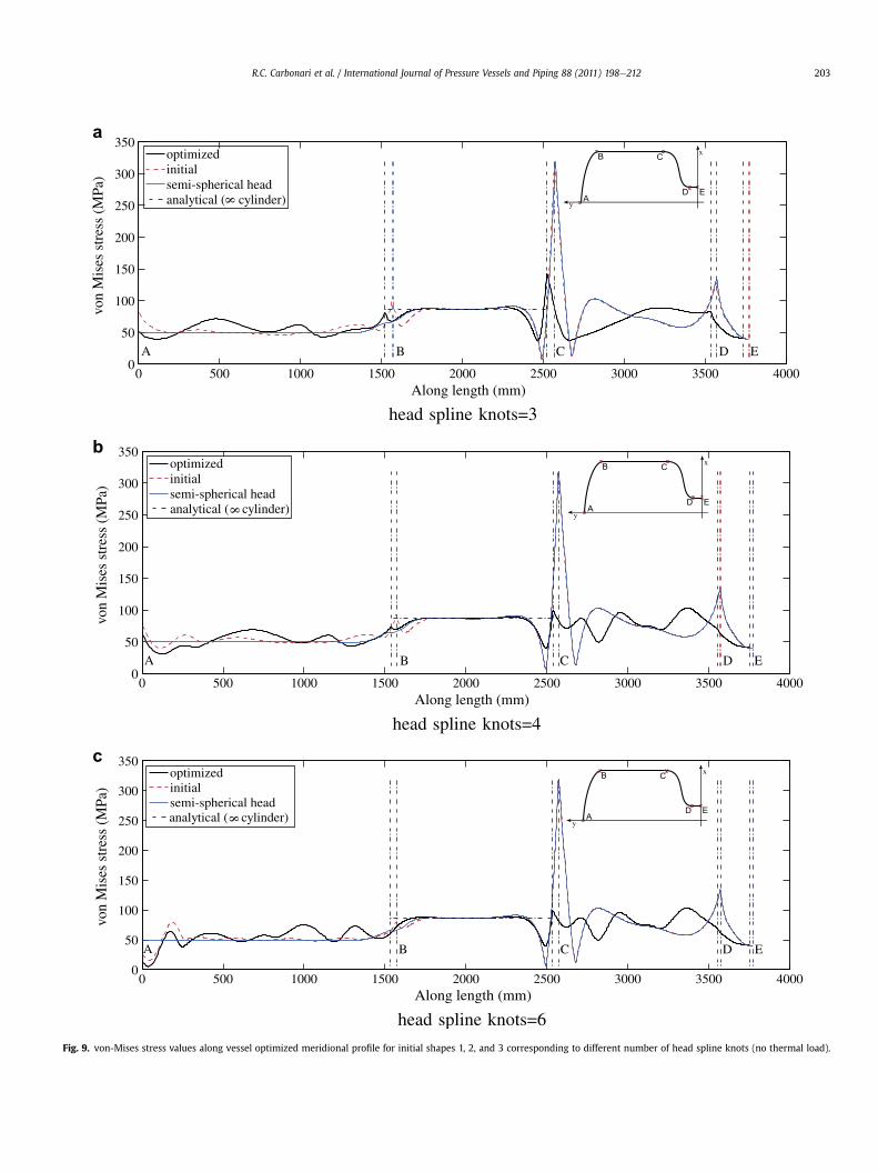
Fig. 9. von-Mises stress values along vessel optimized meridional profile for initial shapes 1, 2, and 3 corresponding to different number of head spline knots (no thermal load).
R.C. Carbonari et al. / International Journal of Pressure Vessels and Piping 88 (2011) 198e212 203

Table 4Maximum von-Mises stress values (MPa), where subscripts h, n, 0, ss, and h2 indicatehead, nozzle, initial shape, standard spherical, and cylindrical region h2, respectively(sah2
¼ 86:6 Mpa for an infinite cylinder).
Example sh sh0 sss sn sn0 sh2 sh20
Fig. 9(a) 80.4 101.3 67.0 142.9 318.6 89.0 91.5Fig. 9(b) 73.9 92.9 67.0 103.3 318.6 89.0 91.5Fig. 9(c) 75.6 79.4 67.0 103.4 318.6 89.0 91.5Fig. 12(a) 303.5 292.0 261.6 276.6 452.7 276.5 278.0Fig. 12(b) 302.1 286.5 261.6 276.6 452.7 276.5 278.0Fig. 12(c) 256.6 276.2 261.6 276.6 452.7 276.5 278.0Fig. 9(a, b and c) thermal loadFig. 12(a, b and c) no thermal load
R.C. Carbonari et al. / International Journal of Pressure Vessels and Piping 88 (2011) 198e212204
constraints are introduced in the optimization problem. Thus, thecomplexity constraints for the head region are defined as:
y1 � ymaxy1 � y2 � eyi � yiþ1 � eynh � ymin ði ¼ 2 . nh� 1Þ
(2)
where yi are shown in Fig. 1 and nh is the number of knots in thehead region; ymax and ymin are the maximum and minimum valuesallowed for these coordinates, respectively; and e is a small number.For the nozzle, the complexity constraints are defined as:
x1 � xmaxx1 � x2 � dxj � xjþ1 � dxnn � xmin ði ¼ 2 . nn� 1Þ
(3)
where xi are shown in Fig. 1 and nn is the number of knots in thenozzle region; xmax and xmin are the maximum and minimumvalues allowed for these coordinates, respectively; and d is a smallnumber.
A material volume constraint is not specified because thechange of spline length is not significant during the optimization.Althoughmaterial volume constraint is not included, it is verified “aposteriori”.
3.3. Summary and remarks
Based on the above considerations, shape optimization problemcan be defined as:
0 50 100 1504
5
6
7
8
9
10
Iter
Mul
ti-ob
ject
ive
func
tion p = 1
Fig. 10. Convergence of multi-objective function for initial shape 1, corre
Min : Fðyh; xnÞSubjected to :
y1 � ymax x1 � xmax�y1 þ y2 � �e �x1 þ x2 � �d�yi þ yiþ1 � �e �xj þ xjþ1 � �d�ynh � �ymin ði ¼ 2 . nh� 1Þ�xnn � �xmin ðj ¼ 2 . nn� 1Þ
The numerical implementation of this defined shape optimiza-tion problem is described in the next section. Mechanical (pressure)and thermal loads (temperature difference) are considered. Inaddition, in the case of vessels subjected to internal pressure,buckling instability may occur for head and nozzle (mainly head) ifhoop stresses reach negative values [19]. The head buckling is moresusceptible to occur for vessels with large diameter/thickness ratioand high yield stress values [20]. Because during the optimizationprocess the head and nozzle geometry is changed, then a geometrysusceptible to buckling problems may be obtained. In this work, noconstraint is specified for the hoop stress in the optimizationproblem, its value is only verified “a posteriori” in the final result.
4. Numerical implementation of shape optimization program
The flowchart of the program is illustrated in Fig. 2. The programis implemented using the commercial software MATLAB [21] andANSYS [22]. All processes, including the optimization process andfile input and output from ANSYS are controlled byMATLAB. ANSYSinput files contain all the information of the pressure vesselcomputer-aided engineering (CAE)model. After obtaining the inputfiles, the MATLAB routine executes ANSYS, and an output file isgenerated, which is in turn read by MATLAB.
The pressure vessel is modeled by using the 2D-axisymmetricshell finite element type SHELL208 [22]. The default option for thiselement employs two nodes (linear displacement interpolation ofthe midsurface) and three integration points through the thickness(at the bottom, at the top and at the midsurface), as illustrated byFig. 3. This element has the capability of modeling bending andmembrane stiffness, and torsion. It gives, as a result, the longitu-dinal, meridional, and von-Mises stress values at the Gauss inte-gration points. The von-Mises stress considered and presented forall results in this work are the maximum values among the Gaussintegration points through the thickness.
Fig. 4 illustrates the mechanical and thermal boundary condi-tions applied to the model. In this figure, Ti and Te are internal andexternal temperature, respectively, and P is the internal pressure.
200 250 300ations
p = 5
sponding to head spline knot number equal to 3 (no thermal load).

R.C. Carbonari et al. / International Journal of Pressure Vessels and Piping 88 (2011) 198e212 205
Following the flowchart in Fig. 2, the initial data of the optimi-zation problem is the geometry of the pressure vessel, whichcontains the spline knot coordinates (or design variable initialvalues), material properties, load and boundary conditions. Thespline curves are obtained using the MATLAB function spline,considering the design variables yh and xn and discretizationparameters nh and nn for head and nozzle, respectively. The usedfunction spline considers a cubic spline data interpolation, which isgenerated using the following parameters:
Sh ¼ f ðxh; yhÞ ¼ ½splineðh; xi;1 : nhÞ; splineðh; yi;1 : nhÞ� (4)
Sn ¼ f ðxn;ynÞ ¼hspline
�n;xj;1 :nn
�;spline
�n;yj;1 :nn
�i(5)
where Sh and Sn are matrices that contain the cubic spline knotcoordinates for the head and for the nozzle, respectively. The headspline Sh is obtained considering the tangent at the symmetry pointequal to zero (see Fig. 5). As mentioned before, xh and yn arecalculated as functions of yh and xn, respectively, considering theconstraint that knots must move in the normal direction.
In the sequence, the CAE model is defined including algorithmicparameters and mesh attributes such as the finite element type,number of nodes and elements, loads and boundary conditions.Once the CAE model is built, the ANSYS solver is executed byrunning a linear static analysis, which generates output files that
0 500 10000
500
1000
1500
2000
2500
3000
Dimension in x (mm)
Dim
ensi
on in
y (
mm
)
initialoptimized
head spline knots=3
0 500 1000
500
1000
1500
2000
2500
3000
Dimension in x (
Dim
ensi
on in
y (
mm
)
head spline kno
a
c
Fig. 11. Optimization result obtained for initial shapes 1, 2, and 3 corresponding to differentare given beside each figure.
contain the results of von-Mises mechanical stresses (sh and sn) ateach finite element integration point.
The sensitivity analysis of the multi-objective function in rela-tion to design variables is obtained by using the central finitedifference scheme. Thus, for the gradient numerical calculations itis necessary to obtain the perturbations dh and dn defined in theexpressions below,
vFvyi
yFðyi þ dhÞ � Fðyi � dhÞ
2dh(6)
vFvyi
yFðxi þ dnÞ � Fðxi � dnÞ
2dn(7)
Notice that y and x coordinates are defined as design variables forhead and nozzle, respectively. Moreover, dh and dn are calculatedconsidering a fraction of the spline length Lh or Ln, which is givenby:
Lh ¼H nhj¼1 Sh
�xj; yj
�ds
Pyi
0dh ¼ fhLh (8)
Ln ¼H nni¼1 Snðxi; yiÞdsP
xj0dn ¼ fnLn (9)
0 500 10000
500
1000
1500
2000
2500
3000
Dimension in x (mm)
Dim
ensi
on in
y (
mm
)
initialoptimized
head spline knots=4
0mm)
initialoptimized
ts=6
b
number of head spline knot and with thermal load. Detailed views of head and nozzle

0 500 1000 1500 2000 2500 3000 3500 40000
100
200
300
400
500
Along length (mm)
von
Mis
esst
ress
(MPa
)
optimizedinitialsemi-spherical head
A EDCB
x
yA
B C
D E
head spline knots=3
0 500 1000 1500 2000 2500 3000 3500 40000
100
200
300
400
500
Along length (mm)
von
Mis
esst
ress
(MPa
)
optimizedinitialsemi-spherical head
A EDCB
x
yA
B C
D E
head spline knots=4
0 500 1000 1500 2000 2500 3000 3500 40000
100
200
300
400
500
Along length (mm)
von
Mis
esst
ress
(MPa
)
optimizedinitialsemi-spherical head
A EDCB
x
yA
B C
D E
head spline knots=6
Fig. 12. von-Mises stress values along vessel optimized meridional profile for initial shapes 1, 2, and 3 corresponding to different number of knots at head spline and withthermal load.
R.C. Carbonari et al. / International Journal of Pressure Vessels and Piping 88 (2011) 198e212206
0 50 100 150 200 250 3006
7
8
9
10
11
12
Iterations
Mul
ti-ob
ject
ive
func
tion
p = 1 p = 7
Fig. 13. Convergence of multi-objective function for initial shape 3, corresponding to head spline knot number equal to 6 and thermal load.
R.C. Carbonari et al. / International Journal of Pressure Vessels and Piping 88 (2011) 198e212 207
where fh and fn are percentage values specified for head andnozzle, respectively.
To solve the optimization problem, the gradient based sequen-tial linear programming (SLP) optimization algorithm is used [23].The SLP is implemented using the available function linprog (LinearProgramming) from MATLAB. The SLP requires that a moving limitscheme be defined for design variables. These moving limits alsohelp to control the numerical oscillations of multi-objective func-tion gradients. The amplitude of the moving limits is defined asa function of coefficients qh and qn. These coefficients are calculatedby using a scheme similar to the one used for calculating dh and dn.Thus, qh and qn are obtained considering a fraction of the splinelength (Lh or Ln), which is given by:
qh ¼ ahLh; qn ¼ anLn (10)
where qh and qn are the moving limits coefficients for the head andnozzle, respectively, which are updated at each iteration. Accord-ingly, ahand an are percentage values specified for head andnozzle, respectively. Therefore, the upper and lower boundsobtained using the moving limits routine for the design variablesare calculated by:
0 500 10000
500
1000
1500
2000
2500
Dimension in x (mm)
Dim
ensi
on in
y (
mm
)
initialoptimized
Fig. 14. Optimization result for example 2, considering h2 ¼ 1000 mm and free tangentangle at head symmetry knot (no thermal load). Detailed views of head and nozzle aregiven beside figure.
yiL ¼ yi � qhili (11)
yiU ¼ yi þ qhili ði ¼ 1 . nhÞ (12)
xjL ¼ xj � qnjlj (13)
xjU ¼ xj þ qnjlj ðj ¼ 1 . nnÞ (14)
where subscripts L and U are lower and upper bounds, respectively.The parameters li and lj are updated during the optimizationprocess, and thus the moving limit steps decrease by 5% with theconvergence of multi-objective function.
Thus, the following optimization problem at each iteration isdefined:
Min : Fðyh;xnÞSubjected to :
y1 � ymax x1 � xmax�y1 þ y2 � �e �x1 þ x2 � �d�yi þ yiþ1 � �e �xj þ xjþ1 � �d�ynh � �ymin i ¼ 2 . nh�xnn � �xmin j ¼ 2 . nnykL � yk � ykU k ¼ 1 . nhxlL � xl � xjU l ¼ 1 . nn
0 500 10000
500
1000
1500
2000
2500
Dimension in x (mm)
Dim
ensi
on in
y (
mm
)
initialoptimized
Fig. 15. Optimization result for example 2, considering h2 ¼ 1000 mm and null tangentangle at head symmetry point (no thermal load). Detailed views of head and nozzle aregiven beside figure.

0 500 1000 1500 2000 2500 3000 35000
50
100
150
200
250
300
350
Along length (mm)
von
Mis
esst
ress
(MPa
)
optimizedinitialelliptical head
A EDCB
x
yA
B C
D Eanalytical ( cylinder)8
Fig. 16. von-Mises stress values along vessel optimized meridional profile obtained for example 2, considering h2 ¼ 1000 mm and free tangent angle at head symmetry point (nothermal load).
R.C. Carbonari et al. / International Journal of Pressure Vessels and Piping 88 (2011) 198e212208
The optimization problem is updatedwith the new design variablesand the loop is continued until convergence of the multi-objectivefunction and, finally, the optimal shape of the vessel is obtained.
5. Numerical results
This section illustrates the integrated approach for pressurevessel design, in which the entire vessel is considered during theoptimization process.
Fig. 5 shows the finite element model adopted for the vesselshape optimization. As indicated before, a 2D-axisymmetric shellelement from ANSYS is used (SHELL 208). The material propertiesare described in Table 1. The initial vessel shape is depicted in Fig. 5,where the values of the parameters d0, h2, h3, h4, and d1 are equal to2000 mm,1000 mm, 866 mm, 200 mm and 1000 mm, respectively.The corresponding initial values for the design variables thatgenerate this geometry, considering spline approximations, aredescribed in Table 2. These initial values for the vessel dimensionsare based on reference [4]. The parameter h1 depends on the initialdesign domain, and the influence of h2 will be analyzed in Section5.2.2. The thickness is uniform along the vessel profile and its valueis equal to 10.0 mm. Examples are presented considering pressure
0 500 1000 15000
50
100
150
200
250
300
350
Along le
von
Mis
esst
ress
(MPa
)
optimizedinitialelliptical head
A B
analytical ( cylinder)8
Fig. 17. von-Mises stress values along vessel optimized meridional profile obtained for examthermal load).
load (P) equal to 1 MPa, and also pressure load together withthermal load. The thermal load is obtained by specifyinga temperature gradient along the thickness. The p exponent valuein Eq. (1) is changed continuously from 1 to 8, and the adoptedparameter values for ah and an (see Eq. (10)) are equal to 25% and50%, respectively, for all examples. The coefficient w (see Eq. (1)) isequal to 0.5 for all examples. These parameters are summarized inTable 3.
5.1. Example 1: pressure vessel design with g ¼ 0
In this example, the objective is to analyze and compare thedesign of pressure vessels with mechanical loading only (pressure)and with both mechanical and temperature loading. An initialshape close (due to spline approximation) to a semi-sphere isadopted for the head (h1 ¼ d0/2). The theoretical semi-sphericalshape presents a uniform low value stress distribution, witha peak stress at the junction between cylinder and semi-sphere.Thus, it is a quasi-optimum result from the stress point of view,however, it is difficult to manufacture. Furthermore, it is a goodinitial guess to evaluate the optimization algorithm and itsevaluation.
2000 2500 3000 3500ngth (mm)
EDC
x
yA
B C
D E
ple 2, considering h2 ¼ 1000 mm and null tangent angle at head symmetry point (no

Table 5Maximum von-Mises stress values (MPa), where subscripts h, n, 0, se, and h2 indicatehead, nozzle, initial shape, standard ellipse, and cylindrical region h2, respectively(sah2
¼ 86:6 Mpa for infinite cylinder).
Example sh sh0 sse sn sn0 sh2 sh20h2 g
Fig. 16 143.2 153.4 150.6 141.3 319.0 90.4 91.3 1000 freeFig. 17 140.4 153.0 150.6 103.4 319.0 90.2 91.3 1000 nullFig. 19 242.0 252.0 213.6 201.0 392.8 200.0 201.0 1000 nullFig. 22 141.2 161.1 150.1 109.5 336.0 92.5 95.0 500 nullFig. 23 135.0 162.5 150.3 106.1 333.7 75.7 82.4 250 nullFigs. 16, 17 and
22 and 23no thermal load
Fig. 19 thermal load
0 500 10000
500
1000
1500
2000
2500
Dimension in x (mm)
Dim
ensi
on in
y (
mm
)
initialoptimized
Fig. 18. Optimization result for example 2, considering h2 ¼ 1000 mm and thermalload with null tangent angle at head symmetry point (with thermal load). Detailedviews of head and nozzle are given beside figure.
R.C. Carbonari et al. / International Journal of Pressure Vessels and Piping 88 (2011) 198e212 209
The tangent angle g of the head spline at the vessel symmetryaxis point (see Fig. 5) is kept null during the optimization. Theinternal and external temperatures, Ti and Te, are equal to 250 �C and25 �C, respectively. Three, four and six knot splines are considered todescribe the head shapes, whereas the nozzle shapes are parame-terized using a four knot spline in all examples. This parametrizationchoice is motivated by the convergence characteristics of theproblem, which is easier for the nozzle shape than for the head one.The initial values of design variables are given in Table 2 consideringthree different initial shapes (close to a semi-sphere) correspondingto three, four and six head spline knots (design variables).
Initially, the convergence of the von-Mises stress values(maximum values among the three Gauss integration pointsthrough the thickness) along the vessel meridional profile isanalyzed by considering different discretizations of the finiteelement mesh with and without thermal load. The results obtainedfor the von-Mises stresses are shown in Figs. 6 and 7 (the beginningof the plot is the center point of the head), disregarding andincluding the thermal load, respectively. In both analyses 4, 4, 4,and 2 divisions are adopted for head, cylindrical region h2, nozzle,and h4 region, respectively; and the discretizations employed are10, 20, 50, and 100 finite elements for each division. By analyzingvon-Mises stress values, it can be concluded that stress curvesconverged to the same values along vessel meridional profile.Numerical discretizations with 1100,1150, and 1250 finite elementsfor the problems with three, four and six head spline knots (designvariables) (corresponding to initial shapes 1, 2, and 3 e see Table 2)are adopted, respectively, with and without thermal load. Thesediscretization choices are considered to provide accurate enoughstress results throughout the optimization processes.
5.1.1. Entire vessel design without temperature gradientFirst, a temperature gradient is not considered along the vessel
thickness. The optimization results obtained are shown in Fig. 8considering different number of head spline knots (correspondingto initial shapes 1, 2, and 3). Fig. 9(a, b and c) show the variation ofvon-Mises stresses along the meridional profile of the entire vesselfor three, four, and six knot splines corresponding to initial shapes1, 2, and 3, respectively.
The analytical stresssah2(along the cylindrical region h2, see Fig. 5)
of an infinite cylinder calculated using membrane theory is equal to86.6 MPa [10]. For all plots in this work, “analytical”means the von-Mises stress result for an infinite cylinder. The maximum von-Misesstress in the head and nozzle are presented in Table 4. Fig. 10 showsthe convergence of themulti-objective function for head splinewith3 knots (and initial shape 1). It illustrates the effect of the p-contin-uation strategy in the optimization process - see Eq. (1).
5.1.2. Entire vessel design considering temperature gradientNow, a temperature gradient is added along the thickness of the
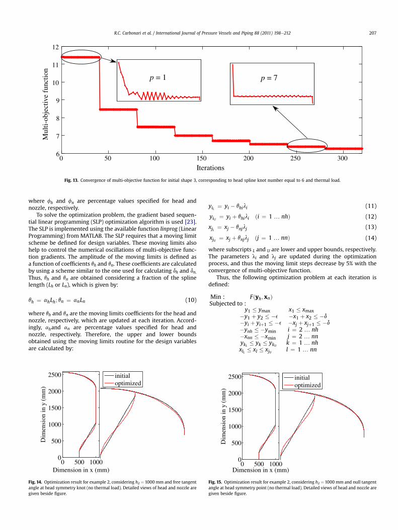
vessel model. The objective is to analyze the effect of thermalloading in the final design vessel shape. The results obtained byshape optimization are illustrated in Fig. 11 considering differentnumbers of head spline knots (corresponding to initial shapes 1, 2,and 3). Fig. 12(a, b, and c) show the variation of von-Mises stressesalong the meridional profile of the entire vessel for differentnumbers of head spline knots (and initial shapes). Fig. 13 shows theconvergence of the multi-objective function considering a numberof head spline knots equal to 6 (and initial shape 3).
5.1.3. DiscussionThe maximum von-Mises stress values in the head and nozzle
are presented in Table 4, and are indicated in the plots of Figs. 9 and12. As expected, in all cases the obtained optimized stress distri-butions are usually not better than a semi-spherical head (which,
however, is difficult to manufacture). From Fig. 9, it is noticed thatfor the three cases analyzed without thermal load, the maximumhead stresses are smaller than the cylinder stresses. As the numberof spline knots increases, the stress value oscillation also increases,an effect that is not observed in the design problem with thethermal gradient, as shown in Fig. 12. In addition, the stress valuesin the junction between head and cylinder decrease (see Table 4)and the convergence stability is improved either in the presence orabsence of the thermal gradient.
Furthermore, a smooth stress distribution is obtained for thehead using a small number of spline knots (3 and 4) either with orwithout thermal load, as shown in Figs. 9 and 11(a, b), Fig. 12(aand b). A similar conclusion was obtained by Zhu and Boyle [4]considering the separate head design without thermal load. Whena six knot spline (corresponding to initial shape 3) and thermal loadare considered, the maximum head stress (256.6 MPa) is smallerthan even the semi-sphere stress (261.6 MPa) - see Table 4.
Concerning the nozzle, when the thermal gradient is notconsidered, its shape and stress distribution oscillates between tworesults which are shown by solid lines (optimized) in Fig. 9(a and b)This does not occur when the thermal gradient is considered, that is,only one local optimum is obtained, as shown in Fig. 12. Meanwhile,it is noticed that an increase in the number of spline knots in thenozzle may generate geometries with slightly higher stress values(see Table 4). In addition, when the thermal load is considered, thenozzle stresses for optimized shape approach the cylinder stresses.
5.2. Example 2: pressure vessel considering influence of angle g atthe head top
In this example, an initial shape close (due to spline approxi-mation) to an elliptical head shape (h1 ¼ d0/4) is considered.A control of the g tangent angle at the point of symmetry of the

0 500 1000 1500 2000 2500 3000 350050
100
150
200
250
300
350
400
Along length (mm)
von
Mis
esst
ress
(MPa
)
optimizedinitialelliptical head
A EDCB
x
yA
B C
D E
Fig. 19. von-Mises stress values along vessel optimized meridional profile obtained for example 2, considering h2 ¼ 1000 mm and null tangent angle at head symmetry point (withthermal load).
R.C. Carbonari et al. / International Journal of Pressure Vessels and Piping 88 (2011) 198e212210
vessel (see Fig. 5) is implemented. Another important aspect in thisexample is to verify how the shape optimization result is affectedby the variation of the dimension h2 (see Fig. 5). Thus, for example,for large h2 dimension (approaching an infinite cylinder), theproblem may be uncoupled, and the optimization problem may besolved for the nozzle and the head separately. The thermal load isconsidered along the vessel thickness for one of the cases analyzedin this example.
Seven and four knot splines are considered to describe the headand nozzle shapes, respectively, giving a total of eleven designvariables in the design optimization problem. The initial values ofdesign variables corresponding to a shape close to an elliptical headshape are given in Table 2. A discretization equal to 1300 finiteelements is adopted for all cases in this example, i.e. with andwithout thermal load.
5.2.1. Entire vessel design considering pressure and temperatureloading
In this first case, a temperature gradient is not considered alongthe vessel thickness. Thus, the objective of this first case is toanalyze the influence of the g tangent angle at the head top (vesselsymmetry axis point - see Fig. 5). The angle valuewill be consideredeither null or variable and h2 is kept constant and equal to1000 mm. Figs. 14e17 show the final results of the shape
0 500 10000
500
1000
1500
2000
Dimension in x (mm)
Dim
ensi
on in
y (
mm
)
initialoptimized
Fig. 20. Optimization result for example 2, considering h2 ¼ 500 mm (no thermalload). Detailed views of head and nozzle are given beside figure.
optimization and the von-Mises stress distribution, consideringfree and null angle. The results obtained by the optimization arecompared through von-Mises stress plots with the correspondingstandard elliptical head shape vessel which is known to provide anoptimum stress distribution [4].
Therefore, from Figs. 16 and 17 the maximum von-Mises stressvalues for optimized head shape considering initial shape with freeangl (143.2 MPa), with null angl (140.4 MPa), and correspondingstandard elliptical head shape (150.6 MPa) are, respectively, 65.4%,62.1%, and 73.9%, greater than the corresponding analytical stresssah2
of the infinite cylindrical vessel. The difference between theanalytical (86.6 MPa) and numerical stress for the cylindrical region(h2¼1000mm) (90.2MPa), is 4%. For the nozzle, the optimized von-Mises stress is 63.2% and 19.4% greater than sah2
considering free(variable) (141.3 MPa) and null angle (103.4 MPa), respectively, asdetailed in Table 5. In both cases, optimal results obtained by shapeoptimization are better than using a corresponding elliptical head,and obtained stress values for the head and nozzle, considering nullangle, are lower than maximum stress value for a vessel with cor-responding elliptical head. The stress values obtained with nullangle condition are lower than stress values obtained consideringfree (variable) angle. It seems that the null angle solution is a localminimum which is difficult to reach. The optimization taking thedesign variable g into account must be conducted with care, thus,the null angle condition will be considered for the next results.
0 500 10000
500
1000
1500
Dimension in x (mm)
Dim
ensi
on in
y (
mm
)
initialoptimized
Fig. 21. Optimization result for example 2, considering h2 ¼ 250 mm (no thermalload). Detailed views of head and nozzle are given beside figure.
0 500 1000 1500 2000 2500 30000
50
100
150
200
250
300
350
Along length (mm)
von
Mis
esst
ress
(MPa
)optimizedinitialelliptical head
A EDCB
x
yA
B C
D Eanalytical ( cylinder)8
Fig. 22. von-Mises stress values along vessel optimized meridional profile obtained for example 2, considering h2 ¼ 500 mm (no thermal load).
R.C. Carbonari et al. / International Journal of Pressure Vessels and Piping 88 (2011) 198e212 211
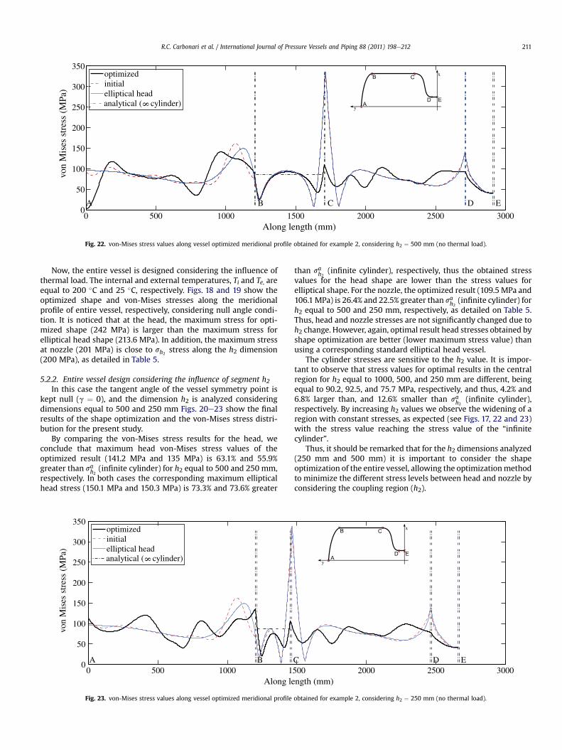
Now, the entire vessel is designed considering the influence ofthermal load. The internal and external temperatures, Ti and Te, areequal to 200 �C and 25 �C, respectively. Figs. 18 and 19 show theoptimized shape and von-Mises stresses along the meridionalprofile of entire vessel, respectively, considering null angle condi-tion. It is noticed that at the head, the maximum stress for opti-mized shape (242 MPa) is larger than the maximum stress forelliptical head shape (213.6 MPa). In addition, the maximum stressat nozzle (201 MPa) is close to sh2
stress along the h2 dimension(200 MPa), as detailed in Table 5.
5.2.2. Entire vessel design considering the influence of segment h2In this case the tangent angle of the vessel symmetry point is
kept null (g ¼ 0), and the dimension h2 is analyzed consideringdimensions equal to 500 and 250 mm Figs. 20e23 show the finalresults of the shape optimization and the von-Mises stress distri-bution for the present study.
By comparing the von-Mises stress results for the head, weconclude that maximum head von-Mises stress values of theoptimized result (141.2 MPa and 135 MPa) is 63.1% and 55.9%greater than sah2
(infinite cylinder) for h2 equal to 500 and 250 mm,respectively. In both cases the corresponding maximum ellipticalhead stress (150.1 MPa and 150.3 MPa) is 73.3% and 73.6% greater
0 500 1000 10
50
100
150
200
250
300
350
Along le
von
Mis
esst
ress
(MPa
)
optimizedinitialelliptical head
A B
analytical ( cylinder)8
Fig. 23. von-Mises stress values along vessel optimized meridional profile
than sah2(infinite cylinder), respectively, thus the obtained stress
values for the head shape are lower than the stress values forelliptical shape. For the nozzle, the optimized result (109.5 MPa and106.1MPa) is 26.4% and 22.5% greater than sah2
(infinite cylinder) forh2 equal to 500 and 250 mm, respectively, as detailed on Table 5.Thus, head and nozzle stresses are not significantly changed due toh2 change. However, again, optimal result head stresses obtained byshape optimization are better (lower maximum stress value) thanusing a corresponding standard elliptical head vessel.
The cylinder stresses are sensitive to the h2 value. It is impor-tant to observe that stress values for optimal results in the centralregion for h2 equal to 1000, 500, and 250 mm are different, beingequal to 90.2, 92.5, and 75.7 MPa, respectively, and thus, 4.2% and6.8% larger than, and 12.6% smaller than sah2
(infinite cylinder),respectively. By increasing h2 values we observe the widening of aregion with constant stresses, as expected (see Figs. 17, 22 and 23)with the stress value reaching the stress value of the “infinitecylinder”.
Thus, it should be remarked that for the h2 dimensions analyzed(250 mm and 500 mm) it is important to consider the shapeoptimization of the entire vessel, allowing the optimizationmethodto minimize the different stress levels between head and nozzle byconsidering the coupling region (h2).
500 2000 2500 3000ngth (mm)
EDC
x
yA
B C
D E
obtained for example 2, considering h2 ¼ 250 mm (no thermal load).

R.C. Carbonari et al. / International Journal of Pressure Vessels and Piping 88 (2011) 198e212212
6. Conclusions
In this work, an integrated shape optimization study of pressurevessels is conducted considering a model of the entire pressurevessel. A proper multi-objective function based on a logarithmic ofa p-root of summation of p-exponent terms has been defined forminimizing the tank maximum von-Mises stress.
For vessels with mechanical loading only and initial shapes closeto a semi-sphere, one notices that the maximum head stresses aresmaller than the cylinder stresses. In addition, as the number ofspline knots increases, the stress value oscillation also increases,a patternwhich is not observed in the designproblemswith thermalgradient included. However, as the number of spline knots increases,the stress values in the junction between head and cylinder decreaseand the convergence stability is improved either with or withouta thermal gradient. Remarkably, a smooth stress distribution isobtained for the head region evenwhen using just a small number ofspline knots (3 and 4). Another interesting aspect observed for thecases investigated is that the nozzle stresses approach the cylinderstresses when the thermal load is considered.
By comparing the standard elliptical head results, we concludedthat the stress values are smaller for the optimized result than forthe elliptical head when no thermal load is considered. In addition,lower stress values are obtained considering the null angle condi-tion (g ¼ 0). Thus, the null angle condition seems to give a bettervessel design for stress value criteria.
When analyzing the influence of segment h2 in the absence ofthermal gradients, one notices that the cylinder stresses are moresensitive to the h2 value than head and nozzle stresses. Thus,depending on the value of the connecting segment h2, it is important toconsider the shape optimization of the entire vessel, allowing theoptimization method to minimize the different stress levels betweenhead and nozzle by considering the coupling cylindrical region (h2), assuccessfully achieved in this work.
As future work, the design of pressure vessels taking intoaccount non-linear effects, such as pressure limit, will be per-formed. These issues are presently under consideration.
Acknowledgment
All authors thank PETROBRAS for supporting this researchthrough GALILEU project n. 0050.0042368.08.4. The first authoralso acknowledges FUSP (Foundation of University of São Paulo). Inaddition, the last author thanks CNPq (project number no 303689/2009-9).
References
[1] Middleton J, Owen DRJ. Automated design optimization to minimize shearingstress in axisymmetric pressure-vessels. Nuclear Engineering and Design1977;44(3):357e66.
[2] Middleton J. Optimal-design of torispherical pressure-vessel end closures.Engineering Optimization 1979;4(3):129e38.
[3] Blachut J. Minimum weight of internally pressurised domes subject to plasticload failure. Thin-walled Structures 1997;27(2):127e46.
[4] Zhu L, Boyle JT. Optimal shapes for axisymmetric pressure vessels: a briefoverview. Journal of Pressure Vessel Technology-transactions of the Asme2000;122(4):443e9.
[5] Mackenzie D, Boyle JT. A method of estimating limit loads by iterative elasticanalysis .1. Simple examples. International Journal of Pressure Vessels andPiping 1993;53(1):77e95.
[6] NadarajahC,MackenzieD,Boyle JT.Amethodofestimating limit loadsby iterativeelastic analysis .2. Nozzle sphere intersections with internal-pressure and radialload. International Journal of Pressure Vessels and Piping 1993;53(1):97e119.
[7] Shi JH, Mackenzie D, Boyle JT. A method of estimating limit loads by iterativeelastic analysis .3. Torispherical heads under internal-pressure. InternationalJournal of Pressure Vessels and Piping 1993;53(1):121e42.
[8] Malinowski M, Magnucki K. Optimal design of sandwich ribbed flat baffleplates of a circular cylindrical tank. International Journal of Pressure Vesselsand Piping 2005;82(3):227e33.
[9] Banichuk NV, Ragnedda F, Serra M. Optimization of mass effectiveness ofaxisymmetric pressure vessels. Structural and Multidisciplinary Optimization2008;35(5):453e9.
[10] Magnucki K, Lewinski J. Fully stressed head of a pressure vessel. Thin-walledStructures 2000;38(2):167e78.
[11] Magnucki K, Szyc W, Lewinski J. Minimization of stress concentration factor incylindrical pressure vessels with ellipsoidal heads. International Journal ofPressure Vessels and Piping 2002;79(12):841e6.
[12] Hammer V, Olhoff N. Topology optimization of continuum structures sub-jected to pressure loading. Structural and Multidisciplinary Optimization2000;19(2):85e92.
[13] Du J, Olhoff N. Topological optimization of continuum structures with design-dependent surface loading - part II: algorithm and examples for 3D problems.Structural and Multidisciplinary Optimization 2004;27(3):166e77.
[14] Zheng B, Chang CJ, Gea HC. Topology optimization with design-dependent pres-sure loading. Structural and Multidisciplinary Optimization 2009;38(6):535e43.
[15] Duysinx P, Bendsoe MP. Topology optimization of continuum structures withlocal stress constraints. International Journal for Numerical Methods inEngineering 1998;43(8):1453e78.
[16] Stump FV, Silva ECN, Paulino GH. Optimization of material distribution infunctionally graded structures with stress constraints. Communications inNumerical Methods in Engineering 2007;23(6):535e51. doi:10.1002/cnm.910.
[17] Amstutz S, Novotny AA. Topological optimization of structures subject to VonMises stress constraints. Structural and Multidisciplinary Optimization 2010;41(3):407e20. doi:10.1007/s00158-009-0425-x.
[18] Blachut J, Magnucki K. Strength, stability, and optimization of pressure vessels:review of selected problems. Applied Mechanics Reviews 2008;61(6):060801.
[19] Soric J. Stability analysis of a torispherical shell subjected to internal-pressure.Computers & Structures 1990;36(1):147e56.
[20] Spence J, Tooth A. Pressure vessel design: concepts and principles. ElsevierApplied Science; 1993.
[21] MATLAB. R2010a documentation. The MathWorks, Inc.; 2010.[22] Ansys. ANSYS advanced analysis techniques guide. ANSYS, Inc.; 2005.[23] Haftka RT, Gürdal Z. Elements of Structural optimization. 3rd ed. Kluwer
Publishers; 1992.