Embed Size (px)
Citation preview

International Journal of Heat and Mass Transfer 55 (2012) 3412–3422
Contents lists available at SciVerse ScienceDirect
International Journal of Heat and Mass Transfer
journal homepage: www.elsevier .com/locate / i jhmt
Effects of temperature dependent properties in electromagnetic heating
Mohammad Robiul Hossan, Prashanta Dutta ⇑School of Mechanical and Materials Engineering, Washington State University, Pullman, WA 99164-2920, United States
a r t i c l e i n f o
Article history:Received 22 July 2011Received in revised form 17 February 2012Accepted 17 February 2012
Keywords:Electromagnetic heatingMicrowaveRadio frequency heatingIntegral transform technique
0017-9310/$ - see front matter � 2012 Elsevier Ltd. Adoi:10.1016/j.ijheatmasstransfer.2012.02.072
⇑ Corresponding author. Tel.: +1 509 335 7989; faxE-mail address: [email protected] (P. Dutta).
a b s t r a c t
Electromagnetic heating such as microwave processing and radio frequency heating becomes very pop-ular because of its non-contact, pollution free and fast distribution of thermal energy within the object ofinterest. In electromagnetic heating, the temperature distribution within a sample greatly depends on thedielectric properties which are functions of electromagnetic frequency, temperature and the compositionof the object. There are many experimental and numerical investigations on electromagnetic heatingbecause of its widespread use in food and other industries, but only few researchers have looked at thisproblem from analytic point of view specifically for the temperature dependent properties. In this paper,we developed an analytic expression for temperature distribution in a three dimensional rectangularobject under electromagnetic heating and presented a method to incorporate temperature dependentproperties of the object in determining the temperature distribution at different times. A simplified Max-well’s equation is solved for plane wave to obtain electric field distribution in the body, and the electro-magnetic power absorption is computed from the electric field distribution which was then used as asource term in the energy equation. Next an unsteady, three dimensional, non-homogenous energy equa-tion is solved by integral transform technique to obtain temperature distribution. Finally, this closed formanalytical solution is used to study the effects of electromagnetic frequency, dielectric properties, andheat transfer coefficient on temperature distribution in a rectangular salmon fillet. It is found that inci-dent frequency, sample thickness and processing time have significant influence on the heating pattern.For radio frequency heating, the temperature dependent dielectric properties influence the temperaturedistribution significantly, but the effect of temperature dependent dielectric properties is less dominantfor the microwave frequency used in the household microwave oven. Our results also show that micro-wave heating provides heterogeneous temperature distribution with alternate hot and cold spots. On theother hand, the radio frequency heating allows almost uniform temperature distribution within the body,which makes it a better choice for quick and convenient heating process especially for commercial andindustrial heating.
� 2012 Elsevier Ltd. All rights reserved.
1. Introduction
In recent days electromagnetic heating is getting popularity asan alternative heating technique in many industries such as wood,textile, biotechnology, materials, and food processing. The efficacyof the electromagnetic heating primarily depends on the ability ofa material to absorb electromagnetic energy and convert it to ther-mal energy [1]. This ability of a material is reflected by dielectricproperties: dielectric constant and dielectric loss. The dielectricconstant is the capacity of a material to store electric energy,whereas the dielectric loss is the measure of the electrical energydissipation into heat. The electromagnetic heating offers fast,non-contact, and pollution free heating with material selectiveheat generation.
ll rights reserved.
: +1 509 335 4662.
Material selective heat generations can be used in fabrication ofpolymer based micro/nanofluidic device [2,3] and sintering pro-cess. Generally in this type of fabrication process, the electromag-netic heating is exploited for bonding purpose by introducing avery thin layer (100 nm–1 micron thick) of highly dielectric mate-rial between two layers. As the electromagnetic waves passthrough the highly dielectric material it gets melted, and hencetwo layers can be bonded irreversibly at moderate pressure. Inaddition to the manufacturing process, the electromagnetic heat-ing can be applied in various biotechnology applications such aspolymerase chain reaction (PCR), temperature induced cell lysis,organic and inorganic chemical synthesis, drug delivery, etc.[2,4–6]. Electromagnetic heating is also very convenient for pro-cessing of low thermal conductive material such as food items asheat starts flowing from the interior of material body to the outersurface. As a matter of fact, the single largest user of electromag-netic heating is the food industry where it is used for thawing,warming, cooking, tempering, blanching, sterilization, etc. [7].

Nomenclature
a length of the object (m)~B magnetic induction (Wb/m2)b thickness of the object (m)c velocity of light (m/s)cp specific heat capacity (J/kg K)~D electric displacement (C/m2)~E electric field (V/m)Ex electric field in x-direction (V/m)f frequency (Hz)~H magnetic field (A/m)~H� complex conjugate of ~H (A/m)Hy magnetic field in y-direction (A/m)h heat transfer coefficient (W/m2 K)~J current density (A/m2)K kernelk thermal conductivity (W/m K)~P Poynting power flux vector (W/m2)_Q power generation (W/m3)R01 reflection coefficientT Temperature (�C)t time (s)T01 transmission coefficientw width of the object (m)X decomposed temperature in x-direction (�C)x location along x coordinate (m)y location along y coordinate (m)z location along z coordinate (m)
Greek symbolsa thermal diffusivity (m2/s)b attenuation factor (rad/m)
v propagation constant (m�1)d reflection phase angle (rad)e permittivity (F/m)e0 free-space permittivity (F/m)c ratio of heat transfer coefficient and thermal conductiv-
ity (m)g eigenvalues in the z-directionj0 relative dielectric constantj00 relative dielectric lossk eigenvalues in the x-directionl permeability (H/m)l0 free-space permeability (H/m)h modified temperature (�C)q density (kg/m3)qv charge density (C/m3)r phase factor (rad/m)r0 electrical conductivity (S/m)f impedance (ohm)x angular frequency (rad/s)n eigenvalues in the y-direction
Subscriptsi initialn eigenvalue indexp eigenvalue indexq eigenvalue index1 surrounding0 free space1 within food/object
M.R. Hossan, P. Dutta / International Journal of Heat and Mass Transfer 55 (2012) 3412–3422 3413
The electromagnetic heating can be divided into two major cat-egories primarily based on the frequency of the incident wave:radio frequency heating (<300 MHz) and microwave heating(300–3000 MHz). Microwave heating is very popular in food indus-tries as well as in home and office to warm up foodstuffs quickly.However, the heterogeneous energy absorption in microwave pro-cessing leads to uneven temperature distribution in the object. Thenon-uniform temperature distribution not only affects the qualityof food but also raises serious concerns for food safety. Unevenheating of foodstuff may leave bacteria or pathogens alive in coldspots and may cause various food borne diseases. Goksoy et al.[8] found that microwave cooking produces islands of cold spotsin poultry meat that facilitates optimum thermal environmentfor microorganism growth. On the other hand, radio frequencyheating generally provides uniform heating with low energy con-sumption [9].
In electromagnetic heating process, a number of factors areresponsible for thermal energy flow within the object. Amongthem material composition, dielectric characteristics, sample sizeand shape, and incident wave frequency are most important. Inan experimental study, Jeong et al. [10] reported that the presenceof salt in meat increase the processing time and non-uniformity oftemperature distribution in microwave heating. The heterogeneityin temperature distribution is also observed in microwave thawingas the dielectric properties vary significantly in frozen and de-frosted zones [1]. In recent years, the effects of size, shape, mois-ture content, and dielectric properties have been studied bothexperimentally and numerically for radio frequency [9,11–13]and microwave [7,8,10–19] heating.
Although there exist extensive experimental and numericalstudies on electromagnetic heating, only a handful of studies usedanalytic techniques to analyze the fundamentals of electromag-netic heating. A close-form analytic expression for temperaturecan be obtained for some simplified problems and these types ofsolutions can reveal the correlation among the characteristics ofelectromagnetic wave, dielectric and thermo-physical propertiesof material subjected to microwave or radio frequency heating. Fle-ischman [20] provided a one dimensional temperature distributionfor microwave heating. Lately, Hossan et al. [21] presented 3D ana-lytical solution for the temperature distribution within a cylindri-cal shaped object for microwave heating. All previous analyticworks assumed constant dielectric properties for a particularworking frequency. However, experimental works [22–23] indicatechanges in dielectric properties within the object as the tempera-ture increases with time. This variation is very significant at thelower end of the electromagnetic frequency [22]. The temperaturedependent dielectric properties alters the absorption capability ofelectromagnetic energy and penetration depth, and hence the nat-ure of transient temperature distribution. Therefore, to predict thetemperature accurately, one has to consider temperature depen-dent property change in the energy equation, especially for theelectromagnetic source term. In this paper, we presented an ana-lytical expression for temperature distribution within a threedimensional rectangular block subjected to electromagnetic heat-ing and proposed an algorithm to evaluate temperature distribu-tion in an object with temperature dependent dielectric properties.
The rest of the paper is organized as follows. First, the theoryand governing equations for electromagnetic heating are provided.

Fig. 1. Schematic of a three dimensional rectangular object heated by electromag-netic wave. In a uniform plane wave, the magnetic field is always perpendicular tothe electric field. The length, width, and height of the object are a, w, and b,respectively.
3414 M.R. Hossan, P. Dutta / International Journal of Heat and Mass Transfer 55 (2012) 3412–3422
Then, an analysis to find the electromagnetic power generationfrom electromagnetic wave is presented. Next, the temperaturedistribution within an object is obtained from the energy equationusing integral transform technique for a short period of processingtime, and then a method is presented to implement temperaturedependent material properties for subsequent time steps. This isfollowed by a discussion on electromagnetic heating of salmon fil-let for various heat transfer coefficients and incident frequencies.Finally, we present our conclusions on this analytic work.
2. Theory
Electromagnetic heating is generally very effective for a dielec-tric medium where heat generation takes place due to the dielec-tric polarization [24]. When an electric field is applied across adielectric medium, the positive and negative charges are alignedtoward cathode and anode respectively forming dipoles. These dip-loes rotate as they try to align themselves with the alternatingelectric field of the electromagnetic waves. Therefore, to studythe electromagnetic heating one has to understand the electro-magnetic field within the system as well as its effects on energyequation.
2.1. Governing equations
The electromagnetic field distribution within a material is gov-erned by Maxwell’s equation as [25]:
~r�~E ¼ � o~Bot
ð1aÞ
~r� ~H ¼~J þ o~Dot
ð1bÞ
~r � ~D ¼ qv ð1cÞ~r �~B ¼ 0 ð1dÞ
where ~E is the electric field, ~B is the magnetic induction, ~H is themagnetic field, ~J is the current density, ~D is the electric displace-ment, and qv is the electric charge density. The time averagedpower flux associated with the electromagnetic wave can be ob-tained as Poynting vector [25]:
~P ¼ 12~E� ~H�� �
ð2aÞ
where ~H� is the complex conjugate of magnetic field. The volumet-ric heat generation can be obtained as
_Q ¼ Reð�~r �~PÞ ð2bÞ
For electromagnetic heating, the temperature distribution withinthe system is governed by the energy equation as [25]:
qCpdTdt¼ ~r � k~rT
� �þ _Q ð3Þ
The left hand side term represents the rate of thermal energychange in the system, while the first term in the right hand side ac-counts for the thermal diffusion.
2.2. Assumptions
In this study, we considered a 3D rectangular shaped object(Fig. 1) which is subjected to electromagnetic heating. For simplic-ity, we assume that electromagnetic waves are transverse (TEM) oruniform plane waves. Although a uniform plane wave cannot beformed in a real system, the electric field distribution obtainedfrom this simplified TEM model can approximate the actual elec-tric field in the rectangular system [25]. In TEM, both electric and
magnetic fields are normal to the direction of propagation(Fig. 1). The other assumptions used to simplify the problem are:
(i) The object of interest obeys linear material constitutivelaws.
(ii) Electroneutrality condition is satisfied within the system.(iii) The magnetic permeability l(x) can be approximated by its
value in free space(iv) The effect of moisture is not modeled explicitly, but it is
taken into consideration through temperature dependentdielectric properties of the material. This is reasonable forelectromagnetic heating as the dielectric properties are verystrong function of material composition.
(v) Material properties, such as thermal conductivity and spe-cific heat are temperature independent.
3. Analysis
3.1. Electromagnetic power
Maxwell’s equations can be simplified by using the assumptionsmentioned above and by applying following material constitutiverelations [25]
~J ¼ r0~E ð4aÞ~D ¼ e~E ð4bÞ~B ¼ l~H ð4cÞ
where r0 is the electrical conductivity, e is the permittivity, and l isthe magnetic permeability. If electromagnetic incident rays arepropagating in the z-direction, the only non-zero component ofelectric field is E = Ex. Therefore, for system shown in Fig. 1, thesimplified equation for electric field can be written as [7]:
d2E
dz2 þ v2E ¼ 0 ð5Þ
where v is the propagation constant, and it can be given asv2 ¼ x2l0e0ðj0 þ ij00Þ. The propagation constant can also be ex-pressed as v = r + ib, where the phase factor and the attenuationfactor can be given by Eqs. (6a) and (6b), respectively [7]

M.R. Hossan, P. Dutta / International Journal of Heat and Mass Transfer 55 (2012) 3412–3422 3415
r ¼ 2pfc
ffiffiffiffiffiffiffiffiffiffiffiffiffiffiffiffiffiffiffiffiffiffiffiffiffiffiffiffiffiffiffiffiffiffiffiffiffiffiffiffiffiffiffiffiffij0
ffiffiffiffiffiffiffiffiffiffiffiffiffiffiffiffiffiffiffiffiffiffi1þ tan2 d
pþ 1
� �2
vuutð6aÞ
b ¼ 2pfc
ffiffiffiffiffiffiffiffiffiffiffiffiffiffiffiffiffiffiffiffiffiffiffiffiffiffiffiffiffiffiffiffiffiffiffiffiffiffiffiffiffiffiffiffiffij0
ffiffiffiffiffiffiffiffiffiffiffiffiffiffiffiffiffiffiffiffiffiffi1þ tan2 d
p� 1
� �2
vuutð6bÞ
For a uniform plane electromagnetic wave propagating in the zdirection of a rectangular block (Fig. 1), the boundary conditionsat the top and bottom surfaces are given by
E0 ¼ E1 ð7aÞ1
l0xdE0
dz¼ 1
l1xdE1
dzð7bÞ
where 0 and 1 indicate the free and object, respectively. The electricfield distribution within the object of interest can be expressed as:
E ¼ T01E0
1þ R01eiv1beiv1z þ eiv1ðb�zÞ� �
ð8Þ
where the transmission and the reflection coefficients are
T01 ¼2f1
f1 þ f0ð9aÞ
R01 ¼f1 � f0
f1 þ f0ð9bÞ
and the intrinsic impedance [25] is
f ¼ lxv ð9cÞ
On the other hand, if the electromagnetic waves come from the one(bottom) side of the block, then the electric field distribution is:
E ¼ T01E0
1� R201ei2v1b
eiv1z þ R01eiv1ð2b�zÞ� �ð10Þ
Once the electric field distribution is known, the magnetic field dis-tribution can be evaluated eventually as they are related by
dEx
dz¼ ilxHy ð11Þ
Now applying Poynting power theorem, the power dissipated perunit volume can be calculated as [7]:
_Q ¼ 12xe0j00jEj2 ð12Þ
and the volumetric power generation within the sample can be ob-tained as:
_Q ¼ 12xe0j00jE0j2jT01j2
� e�2bz þ e�2bðb�zÞ þ 2 cosð2rz� rbÞe�bb
1þ 2jR01je�bb cosðd01 þ rbÞ þ jR01j2e�2bbð13aÞ
Similarly, for one (bottom) sided incidence of electromagneticwave, the volumetric power generation within the food slab canbe obtained as:
_Q ¼ 12xe0j00jE0j2jT01j2
� e�2bz � 2jR01je�2bb cosðd01 þ 2rðb� zÞÞ þ jR01j2e�2bð2b�zÞ
1� 2jR01j2e�2bb cosð2d01 þ 2rbÞ þ jR01j4e�4bb
ð13bÞ
It is important to note that the source terms presented in Eqs. (13a)and (13b) are a function of temperature (T) in addition to the loca-tion (z) in the direction of wave propagation. The temperaturedependency comes from the dielectric properties such as dielectric
loss and dielectric constant in the phase factor and the attenuationfactor as well as from transmission and reflection coefficients.
3.2. Heat equation and temperature distribution
The energy equation for a three dimensional rectangular block(Fig. 1) subjected to electromagnetic heating can be simplified as
o2Tox2 þ
o2Toyþ o2T
oz2 þ_QðT; zÞ
k¼ 1
aoTot
in 0 6 x < a;
0 6 y < w; 0 < z < b ð14Þ
where a is the thermal diffusivity, k is the thermal conductivity, andT is the temperature. The initial and boundary conditions for thesystem shown in Fig. 1 are:
T ¼ Ti at t ¼ 0 ð15aÞ
koTox¼ h T � T1ð Þ at x ¼ 0; t > 0 ð15bÞ
� koTox¼ h T � T1ð Þ at x ¼ a; t > 0 ð15cÞ
koToy¼ h T � T1ð Þ at y ¼ 0; t > 0 ð15dÞ
� koToy¼ h T � T1ð Þ at y ¼ w; t > 0 ð15eÞ
koToz¼ h T � T1ð Þ at z ¼ 0; t > 0 ð15fÞ
� koToz¼ h T � T1ð Þ at z ¼ b; t > 0 ð15gÞ
The governing equation presented in (14) is nonlinear due to thetemperature dependent source term. Hence, finding a close-formanalytic expression for this system is not trivial. However, onecan consider the problem as linear if the temperature distributionis sought for a very short period of processing time within whichthe variation in dielectric properties is negligible due to small tem-perature change within the body. Here our approach is to solve theabove second order, nonhomogenous partial differential equationusing integral transform technique for a short, but finite period oftime assuming temperature independent source term, and thenuse the solution as initial condition for the next time step. Henceour next step is to solve Eq. (14) for a short period of time(t ? t + s). For electromagnetic heating, the value of s could be61 s in which the generation term remains almost constant. Thus,for a short period (s) of electromagnetic heating, the governingequation for h = T � T1 with temperature independent source termbecomes
o2hox2 þ
o2hoy2 þ
o2hoz2 þ
_QðzÞk¼ 1
aohot
in 0 6 x < a;
0 6 y < w; 0 < z < b ð16Þ
The initial and boundary conditions for the above equation become
h ¼ hi ð17aÞ
� ohoxþ ch ¼ 0 at x ¼ 0 ð17bÞ
ohoxþ ch ¼ 0 at x ¼ a ð17cÞ
� ohoyþ ch ¼ 0 at y ¼ 0 ð17dÞ
ohoyþ ch ¼ 0 at y ¼ w ð17eÞ
� ohozþ ch ¼ 0 at z ¼ 0 ð17fÞ
ohozþ ch ¼ 0 at z ¼ b ð17gÞ

3416 M.R. Hossan, P. Dutta / International Journal of Heat and Mass Transfer 55 (2012) 3412–3422
where c ¼ hk. The partial derivative with respect to x can be elimi-
nated from energy Eq. (16) by introducing Fourier transform as [26]
�hðkn; y; z; tÞ ¼Z a
0Kðkn; xÞhðx; y; z; tÞdx ð18Þ
where the kernels Kðkn; xÞ are the characteristic functions of the fol-lowing eigenvalue problem:
d2X
dx2 þ k2X2 ¼ 0 ð19Þ
� dXdxþ cX ¼ 0 at x ¼ 0 ð20aÞ
dXdxþ cX ¼ 0 at x ¼ a ð20bÞ
where k is the eigenvalue. For the above eigenvalue problem, thekernel can be found as Kðkn; xÞ ¼
ffiffi2pðkn cos knxþc sin knxÞffiffiffiffiffiffiffiffiffiffiffiffiffiffiffiffiffiffiffi
aðk2nþc2Þþ2c
p : The eigenvalueskn are the positive roots of
tanðknaÞ ¼ knð2cÞk2
n � c2ð21Þ
The transformation of energy Eq. (16) with respect to x, through theuse of Eq. (18) yields
�k2n�hþ o2�h
oy2 þo2�hoz2 þ
�_QðzÞk¼ 1
ao�hot
ð22Þ
where �_QðzÞ ¼ _QðzÞ sinðknaÞ � ckn
cosðkmaÞ þ ckn
h i. Similarly the partial
derivative with respect to y and z are removed by Fourier transformand the energy equation becomes an ordinary differential equationwith respect to time (t) as
�a k2n þ n2
p þ g2q
� ����hþU ¼ d���h
dtð23Þ
where
U ¼ sin knað Þ � ckn
cos knað Þ þ ckn
� �sin npw� �
� cnp
cos npw� �
þ cnp
� �
�Z b
0Q zð Þ gq cos gqzþ c sin gqz
� �dz ð24Þ
Here the eigenvalues in the y and z directions can be found from
tanðnpwÞ ¼ npð2cÞn2
p�c2 and tanðgqbÞ ¼ gqð2cÞg2
q�c2, respectively. Now the ordinary
differential equation (Eq. (23)) for transformed temperature ð���hÞ canbe solved as
���h kn; np;gq; t� �
¼ U
a k2n þ n2
p þ g2q
� � 1� e�a k2nþn2
pþg2qð Þs
� �
þ ���hie�a k2
nþn2pþg2
qð Þs ð25Þ
where
���hi ¼ C kn; np;gq; a;w; b; hi
� �¼Z a
0
Z w
0
Z b
0hi kn cos knxþ c sin knxð Þ
� np cos npyþ c sin npy� �
gq cos gqzþ c singqz� �
dxdydz ð26Þ
Our next goal is to apply appropriate inversion techniques to obtainan analytical expression for temperature. First, the inverse Fouriertransform in z direction, ��hðkn; np; z; tÞ ¼
P1q¼1Kðgq; zÞ
���hðkn; np;gq; tÞ isused to obtain transformed temperature as
��h kn; np; z; t� �
¼P1q¼1
ffiffiffi2p
gq cos gqzþ c singqz� �ffiffiffiffiffiffiffiffiffiffiffiffiffiffiffiffiffiffiffiffiffiffiffiffiffiffiffiffiffiffiffiffiffiffiffib g2
q þ c2� �
þ 2cr ���h kn; np;gq; t
� �ð27Þ
Next the inverse Fourier transform for y direction, �hðkn; y; z; tÞ ¼P1p¼1jðnp; yÞ��hðkn; np; z; tÞ is applied to find second transformed
temperature as
�h kn; y; z; tð Þ ¼P1p¼1
P1q¼1
ffiffiffi4p
�np cos npyþ c sin npy� �
gq cos gqzþ c singqz� �
ffiffiffiffiffiffiffiffiffiffiffiffiffiffiffiffiffiffiffiffiffiffiffiffiffiffiffiffiffiffiffiffiffiffiffiffiffiffiffiffiffiffiffiffiffiffiffiffiffiffiffiffiffiffiffiffiffiffiffiffiffiffiffiffiffiffiffiffiffiffiffiffiffiffiffiffiffiffiffiffiffiffiffiffiffiffiffiw n2
p þ c2� �
þ 2c� �
b g2q þ c2
� �þ 2c
� �r
� ���h kn; np;gq; t� �
ð28Þ
Finally, the inverse Fourier transform for x direction, hðx; y; z; tÞ ¼P1n¼1jðkn; xÞ�hðkn; y; z; tÞ is applied to find an analytic expression of
temperature as
h x; y; z; tð Þ ¼P1n¼1
P1p¼1
P1q¼1
A kn; np;gq; x; y; z� �
���h kn; np;gq; t� �
ð29Þ
where Aðkn; np;gq; x; y; zÞ ¼ffiffiffi8p ðkn cos knxþc sin knxÞðnp cos npyþc sin npyÞðgq cos gqzþc sin gqzÞffiffiffiffiffiffiffiffiffiffiffiffiffiffiffiffiffiffiffiffiffiffiffiffiffiffiffiffiffiffiffiffiffiffiffiffiffiffiffiffiffiffiffiffiffiffiffiffiffiffiffiffiffiffiffiffiffiffiffiffiffiffiffiffiffiffi
ðaðk2nþc2Þþ2cÞðwðn2
pþc2Þþ2cÞðbðg2qþc2Þþ2cÞ
pNote that the above expression is only valid for a short period (s) of elec-tromagnetic heating. To obtain temperature distribution at any instantof time (tf), we need to solve the Eq. (16) for N times, where N = tf/s.For each time step, the initial condition for the Eq. (16) is the solutionof previous time step starting with time, t = 0 and boundary conditionsat any time are given by Eqs. (17b)–(17g). Thus, the close form analyticalexpression at tf becomes
h x;y;z; tf
� �¼ T x;y;z; tf
� ��T1 ¼
P1n¼1
P1p¼1
P1q¼1
A kn;np;gq;x;y;z� �
�U x;y;z; tf �s� �
a k2nþ n2
p þg2q
� � 1� e�a k2nþn2
pþg2qð Þs
� �24
35
þP1n¼1
P1p¼1
P1q¼1
A kn;np;gq;x;y;z� �
�C kn;np;gq;a;w;b;h x;y;z; tf �s� �� �
e�a k2nþn2
pþg2qð Þs ð30Þ
4. Results and discussion
In this study close-form analytic expressions of electric fieldand temperature are obtained for electromagnetic heating of a3D rectangular shaped object. Electromagnetic wave frequencyranges from radio frequency (27 MHz) to household microwavefrequency (2450 MHz) is considered here. It is noteworthy to men-tion that the dielectric properties are a strong function of the work-ing frequency as shown in Table 1. The other material propertiesare assumed to be constant for the simplicity in calculation andpresented in Table 2. Although the analytic results presented inthis study are valid for any 3D rectangular shaped object, for illus-tration purpose, we have considered temperature distribution in asalmon fillet (7 � 4 � 1.5 cm). We have specifically addressed theeffect of temperature dependent dielectric properties in evaluatingthe source term from the electric field distribution and its conse-quence in the final temperature distribution. Although dielectricproperties changes with temperature, they can be considered astemperature independent for short period of processing time asthe temperature change is very low (<1 K) if the processing timeis less than 1 s [19,22]. Hence our strategy is to calculate the tem-perature distribution for a short period of time (s) by assumingconstant property and update the source term in the energy equa-tion (Eq. (16)) for the next time step using the latest temperatureinformation. To estimate the temperature dependent source term,we derived empirical relations between dielectric properties of

Table 1Temperature dependent dielectric properties for salmon fillets [22].
Frequency (MHz) Dielectric constant, j0 Dielectric loss, j00
27 j0 = � 4e�04T2 + 0.6064T + 80.87 j00 ¼ 0:0429T2 þ 4:8592T þ 365:7440 j0 = 4e�05T2 + 0.3575T + 77.03 j00 ¼ 0:0284T2 þ 3:4078T þ 248:51
433 j0 = 7e�04T2 � 0.1302T + 63.37 j00 ¼ 0:0027T2 þ 0:3865T þ 29:49915 j0 = 5e�04T2 � 0.1393T + 59.91 j00 ¼ 0:0015T2 þ 0:1498T þ 19:47
2450 j0 = � 0.0045T2 + 0.4793T + 42.03 j00 ¼ �0:0012T2 þ 0:2616T þ 12:45
Table 2Thermal properties and input parameters for analytic calculations.
Parameters Values
Heat transfer coefficient, h (W/m2) 1.5, 10, 25, 50Specific heat capacity, cp (J/kg K) 3589.40Thermal conductivity, k (W/m K) 0.4711Density, q (kg/m3) 1047.89Initial temperature, Ti (�C) 20Surrounding temperature, T1 (�C) 20Thickness of salmon fillet, b (cm) 1.5Incidence electromagnetic energy flux, I (W/cm2) 3.00Length of salmon fillet, a (cm) 7Width of salmon fillet, w (cm) 4
Fig. 2. Algorithm used to calculate temperature distribution within a sample usingtemperature dependent dielectric properties.
M.R. Hossan, P. Dutta / International Journal of Heat and Mass Transfer 55 (2012) 3412–3422 3417
salmon fillet and temperature (Table 1) from experimental data[22] using statistical regression. The algorithm used to calculatethe temperature distribution is shown in Fig. 2.
All temperature results presented in this study are for the two-sided heating cases, though analytical expressions for electric fieldand source term distribution are presented for both one-sided andtwo-sided electromagnetic heating. One can easily find the tem-perature distribution for one-sided heating using the expressionshown in Eq. (13b). In this study, the incidence microwave energyflux (I = 0.5ce0E2) was kept constant at 3 W/cm2; this value corre-sponds to a 1.2 kW household microwave. For the rest of the paper,the microwave frequency and convective heat transfer coefficientare varied from case to case to elucidate the comprehensive effecton temperature distribution during electromagnetic heating.
To validate the algorithm proposed above (Fig. 2), we havesolved the energy equation (Eq. (14)) numerically for convectiveboundary conditions (Eqs. (15b)–(15g) with temperature depen-dent source term. The finite element (numerical) solution is ob-tained by COMSOL 3.2 using general PDE mode where we solvedthe coupled Maxwell’s equation (Eq. (5)) and unsteady energyequation (Eq. (14)) with temperature dependent dielectric proper-ties as shown in Table 1. Fig. 3 shows comparison between numer-ical and analytic results for 75 s of electromagnetic heating withtemperature dependent source term. The temperature distribu-tions along the propagation (z) direction are extracted from the3D solution at the center point of the fillet. Four different electro-magnetic frequencies, radio frequency (40 MHz) and microwavefrequencies (433, 915 and 2450 MHz) which are allocated by theUS Federal Communications Commission (FCC) for industrial heat-ing and microwave oven systems, are used to illustrate the temper-ature distribution within the system.
The temperature results between the numerical method andthe proposed analytical technique have matched perfectly validat-ing the method presented here. Fig. 3 also presents the tempera-ture distributions for constant dielectric properties. It is evidentthat analytic results with constant dielectric properties over-pre-dict the temperature distribution for the radio frequency(f = 40 MHz) as shown in Fig. 3(a). This is because of the fact thatthe penetration depth, a length scale at which the incident energyreduces to its 1/e th value, decreases with temperature for the

Fig. 3. The comparison between numerical and analytic results for temperature distribution with and without temperature dependent dielectric properties for variouselectromagnetic frequencies. Electromagnetic frequencies are (a) f = 40 MHz, (b) f = 433 MHz, (c) f = 915 MHz, and (d) f = 2450 MHz. The convective heat transfer coefficient is10 W/m2 K.
3418 M.R. Hossan, P. Dutta / International Journal of Heat and Mass Transfer 55 (2012) 3412–3422
radio frequency heating which retards the transmission of electro-magnetic waves. On the other hand, for low range of microwavefrequencies (f = 433 MHz and 915 MHz) the constant dielectricproperties under-predict the temperature within the body. Thisunder prediction can be explained from the relationship amongdielectric properties and temperature. Dielectric properties are ex-pressed by two parameters: dielectric constant (j0) and dielectricloss ðj00Þ. The dielectric loss is a measure of heat dissipation inthe body and the dielectric constant quantifies the energy storingability. For lower range of microwave frequency, the dielectric con-stant decreases slightly with temperature while the dielectric lossincreases with temperature. That means, for variable dielectricproperties an object will be able to dissipate more heat with timeand the temperature will be higher than the constant dielectricproperties case. However, the temperature difference betweenconstant and variable (temperature dependent) dielectric casesare much less for the microwave heating than that of the radio fre-quency heating. Interestingly, at the domestic microwave oven fre-quency (f = 2450 MHz), the dielectric properties are not a strongfunction of temperature. Hence, both constant and variable dielec-tric properties predict almost similar temperature, and the minor
discrepancy is due to the small change in properties. In otherwords, the constant dielectric property based temperature predic-tion is acceptable for the frequency used in the household micro-wave oven.
Next we present the three dimensional temperature profiles ina salmon fillet with temperature dependent dielectric propertiesfor microwave (Fig. 4(a)) and radio frequency heating (Fig. 4(b)).The absorbed electromagnetic power is used as a volumetric heatgeneration term in the energy equation, and hence distributionof generation term mainly dictates the temperature distributionin the fillet. For radio frequency heating the generation term is al-most uniform in the propagation direction due to much longerpenetration depth. On the other hand, for microwave heating, thevolumetric heat absorption depends on the electromagnetic fre-quency and thickness of the object in addition to the dielectricproperties [21]. For identical heating power and time, the radio fre-quency heating is able to generate higher temperature increasethan microwave heating.
We also extracted the temperature distribution at different x–y planes from the 3D contour plot, and shown in Figs. 4(c) and(d) for microwave and radio frequency heating. Due to the sym-

Fig. 4. Temperature distribution for 30 s electromagnetic heating of 7 � 4 � 1.5 cm salmon fillet. (a & b) three dimensional contour for f = 2450 MHz and f = 40 MHz. (c & d)Illustration of temperature distribution at four different planes for microwave (f = 2450 MHz) and radio frequency (f = 40 MHz) heating. The convective heat transfercoefficient is 10 W/m2 K.
M.R. Hossan, P. Dutta / International Journal of Heat and Mass Transfer 55 (2012) 3412–3422 3419
metry in the heating conditions, the temperature profiles arepresented for four selected planes at the upper half of the fillet.For radio frequency heating (Fig. 4(d)), the temperature at a par-ticular point remains almost uniform at different sections (z-location) of fillet, but significant changes in temperature are evi-dent for the microwave heating (Fig. 4(c)). The variations in tem-perature do exist in the x–y plane for both radio frequency andmicrowave heating due to convection heat transfer from theboundaries.
The effect of electromagnetic wave frequency on temperaturerise is shown in Fig. 5 for 75 s processing of 1.5 cm thick salmon
fillet. In this case two-dimensional temperature contours are pre-sented along the x–z plane at y = 2 cm for a convective heat transfercoefficient of 10 W/m2 K. For this type of convective heat transferfrom boundary, the temperature profile remains almost onedimensional except very close to the edge. Again the temperaturedistribution along the propagation direction is greatly influencedby the wave frequency. For lower frequency, the temperaturedistribution is more uniform, but heterogeneity in temperature isobserved for the microwave heating with alternate hot and coldspots especially for the domestic microwave oven (f = 2450 MHz)heating.

Fig. 5. Two dimensional temperature contours for 75 s electromagnetic heating of7 � 4 � 1.5 cm salmon fillet at y = 0.02 m plane. Electromagnetic frequencies are (a)f = 27 MHz, (b) f = 40 MHz, (c) f = 433 MHz, (d) f = 915 MHz, and (e) f = 2450 MHz.
Fig. 6. Two dimensional (x–z) temperature contours for 75 s microwave heating of7 � 4 � 1.5 cm salmon fillet at y = 0.02 m and f = 2450 MHz. Heat transfer coeffi-cients are (a) h = 1.5 W/m2 K, (b) h = 10 W/m2 K, (c) h = 25 W/m2 K, and (d)h = 50 W/m2 K.
3420 M.R. Hossan, P. Dutta / International Journal of Heat and Mass Transfer 55 (2012) 3412–3422
Fig. 6 illustrates the effect of heat transfer coefficient on electro-magnetic heating of a salmon fillet at the 2450 MHz frequency.Two dimensional temperature results are presented along the x–zplane for 75 s of microwave heating. The surfaces of the fillet arecooled by the convective heat transfer to the surrounding air space.For 1.5 cm thick sample, core heating as well as surface heatingtake place for 2450 MHz frequency if the convective heat transfercoefficient is small. With the increase in heat transfer coefficient,the surface heating gets reduced because of the higher heat trans-fer rate from the outer surfaces, but the core heating remains lessaffected. This is because of the fact that the salmon fillet has muchlower thermal conductivity and hence, the heat diffusion rate ismuch slower than the generation rate. Thus by increasing the heattransfer coefficient, one can avoid surface heating, but not the coreheating. Core heating can be avoided by pulsating the electromag-netic waves [27]. It is claimed in literature that a pulsatingmicrowave might provide better temperature distribution because
the pulsating time could make up the lag time between the gener-ation and the thermal transport by conduction [27]. Other thermalproperties such as specific heat of the material are also importantin electromagnetic heating (not shown in figures). A material withlower specific heat requires less energy for unit change of temper-ature. For example, fats and oils heat up quickly in microwave dueto their low specific heat capacity, although they have relativelylow dielectric properties [10]. Therefore, the heat transfer coeffi-cient along with the other thermal properties of foodstuff needto be integrated with the factors such as geometry, dielectric prop-erties to predict the accurate temperature distribution.
The one dimensional temperature distributions along the zdirections at the center of the fillet are shown in Fig. 7 for variouselectromagnetic frequencies and processing time. For the sameincident energy flux and time, 40 MHz frequency provides highertemperature because at this frequency the salmon fillet possesseshigher dielectric loss for which it can dissipates energy much fasterrate than any other frequency. The power distribution results pre-sented in Fig. 7 reveals that the volumetric heat generation de-creases with time for the radio frequency processing, butincreases moderately or slightly for the microwave heating. Thedecrease in power absorption for radio frequency (f = 40 MHz) isdue to the lower penetration depth at higher temperature as de-scribed earlier. On the other hand, the slight increase in powerabsorption for f = 433 and 915 MHz is due to increase in the dielec-tric loss with temperature. Since the dielectric properties is a weakfunction of temperature for f = 2450 MHz, the power absorption re-main unaltered with time.
Fig. 7 also shows that the temperature distribution becomes al-most uniform for radio frequency heating, which is highly desir-able from food safety point of view. On the other hand, thealternate hot and cold spots are noticed for higher frequencymicrowave especially for f = 2450 MHz. Similar nonuniform
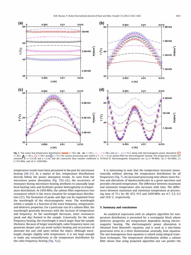
Fig. 7. The center line temperature distribution ( t = 30 s; t = 45 s; t = 60 s and t = 75 s) along with electromagnetic power absorption (t = 30 s; t = 45 s; t = 60 s and t = 75 s) for various processing time within a 7 � 4 � 1.5 cm salmon fillet for electromagnetic heating. The temperature results areextracted at x = 3.5 cm and y = 2 cm, and the convective heat transfer coefficient is 10 W/m2 K. Electromagnetic frequencies are (a) f = 40 MHz, (b) f = 433 MHz, (c)f = 915 MHz, and (d) f = 2450 MHz.
M.R. Hossan, P. Dutta / International Journal of Heat and Mass Transfer 55 (2012) 3412–3422 3421
temperature results have been presented in the past for microwaveheating [20–21]. As a matter of fact, temperature distributionsdirectly follow the power absorption trends. As seen from themicrowave power absorption (Fig. 7(b)–(d)), the occurrence ofresonance during microwave heating attributes to unusually largelocal heating rates and facilitates greater heterogeneity in temper-ature distribution. At 2450 MHz, the salmon fillet experiences tworesonances which is the worst situation for temperature distribu-tion [21]. The formation of peaks and dips can be explained fromthe wavelength of the electromagnetic wave. The wavelengthwithin a sample is a function of the wave frequency, temperature,and dielectric properties. For a particular size of a salmon fillet, thewavelength generally decreases with the increase of temperatureand frequency. As the wavelength decreases, more resonances(peak and dip) formed in the sample. Conversely, for the radiofrequency heating, the wavelength is much larger than the samplethickness. Because of longer wavelength, radio frequency wave canpenetrate deeper and can avoid surface heating and occurrence ofalternate hot and cold spots within the object. Although wave-length changes slightly with temperature, it is not large enoughto make any nonuniformity in the temperature distribution forthe radio frequency heating (Fig. 7(a)).
It is interesting to note that the temperature increases mono-tonically without altering the temperature distribution for allfrequencies (Fig. 7). An increased processing time allows more fric-tion and alterations of dipoles/molecules in a given specimen andprovides elevated temperature. The difference between maximumand minimum temperature also increases with time. The differ-ences between maximum and minimum temperature at process-ing time of 75 s for 40, 433, 915 and 2450 MHz are 4.7, 5.2, 6.3and 10.6 �C, respectively.
5. Summary and conclusions
An analytical expression with an adaptive algorithm for tem-perature distribution is presented for a rectangular block whosedielectric properties are temperature dependent during electro-magnetic heating. The electromagnetic power absorption isobtained from Maxwell’s equation, and is used as a non-lineargeneration term in a three dimensional, unsteady, heat equation.The non homogenous heat equation is solved using integral trans-form techniques. The temperature distribution within a salmonfillet shows that using proposed algorithm one can predict the

3422 M.R. Hossan, P. Dutta / International Journal of Heat and Mass Transfer 55 (2012) 3412–3422
solution of non-linear energy equation from constant propertyanalytical solution. We also presented a rigorous discussion onthe effect of frequency, dielectric properties, and heat transfer coef-ficient on temperature distribution in electromagnetic heating.This study results in following conclusions.
(1) For constant value of dielectric properties, the analyticalsolution of temperature over-predict and under-predict forradio frequency and lower frequency range microwave heat-ing, respectively.
(2) For frequency above 2000 MHz, both constant and variable(temperature dependent) properties provide identical tem-perature profile.
(3) In electromagnetic heating the temperature profile closelyfollow the power absorption distribution except very closeto the surface where the influence of convective heat trans-fer is present.
(4) The volumetric power absorption decreases with tempera-ture for the radio frequency heating, but its value increasesor remain same for the microwave heating.
(5) The temperature distribution in salmon fillet reveals thatelectromagnetic heating with lower frequency waves pro-vides better temperature distribution. In particular, theradio frequency heating gives almost uniform temperaturedistribution.
(6) With same incident energy flux, the radio frequency pro-vides faster heating compared to microwave heating.
(7) In addition to other thermo-physical properties, the heattransfer coefficient of the surroundings has significantimpact on temperature distribution.
References
[1] S. Curet, O. Rouand, L. Boillereaux, Microwave tempering and heating in asingle-mode cavity: numerical and experimental investigations, Chem. Eng.Process. 47 (2008) 1656–1665.
[2] K.F. Lei, S. Ahsan, N. Budraa, W.J. Li, J.D. Mai, Microwave bonding of polymer-based substrate for potential encapsulated micro/naofluidic device fabrication,Sensors Actuat. A 114 (2004) 340–346.
[3] M. Rahbar, S. Chhina, D. Sameoto, M. Parameswarn, Microwave-induced,thermally assisted solvent bonding for low-cost PMMA microfluidic devices, J.Micromech. Microeng. 20 (2010) 15–26.
[4] D. Issadore, K.J. Humphry, K.A. Brown, L. Sandberg, D.A. Weitz, R.M. Westervelt,Microwave dielectric heating of drops in microfluidic devices, Lab Chip 9(2009) 1701–1706.
[5] J.J. Shah, S.G. Sundaresan, J. Geist, D.R. Reyes, J.C. Booth, M.V. Rao, M. Gaitan,Microwave dielectric heating of fluids in an integrated microfluidic device, J.Micromech. Microeng. 17 (2007) 2224–2230.
[6] C.O. Kappe, D. Dallinger, The impact of microwave synthesis in drug discovery,Nature 5 (2006) 51–64.
[7] K.G. Ayappa, H.T. Davis, G. Crapiste, E.A. Davis, J. Gordon, Microwave heatingan evaluation of power formulations, Chem. Eng. Sci. 46 (4) (1991) 1005–1016.
[8] E.O. Goksoy, C. James, S.J. James, Non-uniformity of surface temperatures aftermicrowave heating of poultry meat, J. Microw. Power Electromagn. Energ. 34(3) (1999) 149–160.
[9] V. Romano, F. Marra, A numerical analysis of radio frequency heating of regularshaped foodstuff, J. Food Eng. 84 (2008) 449–457.
[10] J.Y. Jeong, E.S. Lee, J.H. Choi, J.Y. Lee, J.M. Kim, S.G. Min, Y.C. Chae, C.J. Kim,Variability in temperature distribution and cooking properties of ground porkpatties containing different fat level and with/without salt cooked bymicrowave energy, Meat Sci. 75 (2007) 415–422.
[11] F. Marra, J. Lyng, V. Romano, B. McKenna, Radio-frequency heating offoodstuff: solution and validation of a mathematical model, J. Food Eng. 79(2007) 998–1006.
[12] W. Guo, S. Wang, G. Tiwari, J.A. Johnson, J. Tang, Temperature and moisturedependent dielectric properties of legume flour associated with dielectricheating, Food Sci. Technol. 43 (2010) 193–201.
[13] P. Piyasena, C. Dussault, T. Koutchma, H.S. Ramaswamy, G.B. Awuah, Radiofrequency heating of foods: principles, applications and related properties – areview, Crit. Rev. Food Sci. Nutr. 43 (6) (2003) 587–606.
[14] C.J. Budd, A.D.C. Hill, A comparison of models and methods for simulating themicrowave heating of moist foodstuffs, Int. J. Heat Mass Transfer 54 (2011)807–817.
[15] H. Ni, A.K. Datta, K.E. Torrance, Moisture transport in intensive microwaveheating of biomaterials: a multiphase porous media model, Int. J. Heat MassTransfer 42 (1999) 1501–1512.
[16] N. Sakai, C. Wang, An analysis of temperature distribution in microwaveheating of foods with non-uniform dielectric properties, J. Chem. Eng. Jpn. 37(7) (2004) 858–862.
[17] W. Cha-um, P. Ratttanadecho, W. Pakdee, Experimental and numerical analysisof microwave heating of water and oil using a rectangular wave guide:influence of sample sizes, positions, and microwave power, Food Bioprocess.Technol. 23 (2009) 544–558.
[18] P. Rattanadecho, Theoretical and experimental investigation of microwavethawing of frozen layer using a microwave oven (effects of layeredconfigurations and layer thickness), Int. J. Heat Mass Transfer 47 (5) (2004)937–945.
[19] K.G. Ayappa, H.T. Davis, E.A. Davis, J. Gordon, Analysis of microwave heating ofmaterials with temperature dependent properties, AIChE J. 37 (3) (1991) 313–322.
[20] G.J. Fleischman, Predicting temperature range in food slabs undergoing short-term/high-power microwave heating, J. Food Eng. 40 (1999) 81–88.
[21] M.R. Hossan, D.Y. Byun, P. Dutta, Analysis of microwave heating for cylindricalshaped objects, Int. J. Heat Mass Transfer 53 (2010) 5129–5138.
[22] Y. Wang, J. Tang, B. Rasco, F. Kong, S. Wang, Dielectric properties of salmon filletsas a function of temperature and composition, J. Food Eng. 87 (2008) 236–246.
[23] S.O. Nelson, P.G. Bartley Jr., Measuring frequency and temperature dependentproperties of food material, Trans. ASAE 43 (6) (2000) 1733–1736.
[24] B. Zhou, S. Avramidis, On the loss factor of wood during radio frequencyheating, Wood Sci. Technol. 33 (1999) 299–310.
[25] G. Roussy, J.A. Pearce, Foundations and Industrial Applications of Microwavesand Radio Frequency Fields-Physical and Chemical Processes, John Wiley andSons Ltd., West Sussex, England, 1995. pp. 7–25.
[26] S. Kakac, Y. Yener, Heat Conduction, second ed., Hemisphere, New York, 1985.pp. 244–270.
[27] S. Gunasekaran, Pulsed microwave-vacuum drying of food materials, Dry.Technol. 17 (3) (1999) 395–412.