Embed Size (px)
Citation preview

International Journal of Engineering Science 58 (2012) 129–143
Contents lists available at SciVerse ScienceDirect
International Journal of Engineering Science
journal homepage: www.elsevier .com/locate / i jengsci
Effective stiffness and thermal expansion coefficientsof unidirectional composites with fibers surroundedby cylindrically orthotropic matrix layers
I. Tsukrov ⇑, B. Drach, T.S. GrossMechanical Engineering Department, University of New Hampshire, Durham, NH 03824, USA
a r t i c l e i n f o a b s t r a c t
Article history:Received 5 December 2011Accepted 13 February 2012Available online 18 April 2012
Keywords:Carbon/carbon compositesMicromechanicsCylindrically orthotropic layersEffective properties
0020-7225/$ - see front matter � 2012 Elsevier Ltdhttp://dx.doi.org/10.1016/j.ijengsci.2012.03.032
⇑ Corresponding author.E-mail address: [email protected] (I. Tsukrov
An approach to predict the effective thermoelastic properties of unidirectional compositesconsisting of cylindrically orthotropic fibers surrounded by layers of cylindrically orthotro-pic matrix is developed and applied to carbon/carbon composites. Micromechanical mod-eling is based on elastic solutions for basic loadcases including prescribed axial tension,transverse hydrostatic loading, axial and in-plane shear, and unconstrained thermal expan-sion. The composite cylinder assemblage model (Hashin, 1990) is utilized to predict axialelastic properties, transverse bulk modulus and thermal expansion coefficients of the over-all composite. The effective transverse shear modulus is evaluated using a self-consistentmethod. The approach is illustrated by considering a representative carbon/carbon mate-rial system containing pyrolytic carbon matrix of two different texture levels.
� 2012 Elsevier Ltd. All rights reserved.
1. Introduction
This paper deals with micromechanical modeling of unidirectional composites with cylindrically orthotropic constitu-ents. We develop the appropriate homogenization formulae and apply them to carbon/carbon composites (C/C) fabricatedby chemical vapor infiltration (CVI) of carbon fiber preform. The infiltration results in formation of a porous pyrolytic carbon(PyC) matrix organized in the cylindrically orthotropic layers concentrically located around fibers as shown in Fig. 1. Theselayers correspond to different degrees of preferred orientation (or texture) of basal planes in PyC that can be characterized bythe degree of optical anisotropy in polarized light microscopy or by selected area electron diffraction, see Piat et al. (2008)and references therein. The number of layers, their width, order and structure are strongly influenced by the parameters ofinfiltration, such as temperature, pressure, residence time, etc.
Previous efforts to predict the effective elastic properties of C/C composites mostly assumed PyC to be isotropic or trans-versely isotropic (Avery & Herakovich, 1986; Benveniste, Dvorak, & Chen, 1991; Chen, Dvorak, & Benveniste, 1990; Tsukrov,Piat, Novak, & Schnack, 2005). This assumption is useful in the evaluation of contribution of porosity and morphology of thereinforcement to the overall response of the material. However, to analyze the influence of fabrication parameters and tounderstand local stress concentrations in the composite, the anisotropy and inhomogeneity of the matrix material cannotbe neglected.
Our approach to predicting the effective thermoelastic properties of C/C composite is based on the solution of the elas-ticity problem for one fiber surrounded by a number of layers of differently textured cylindrically-orthotropic PyC. By con-sidering mechanical response of this object to several basic load cases (axial tension, transverse hydrostatic tension, axial
. All rights reserved.
).

Fig. 1. SEM micrograph of a carbon fiber surrounded by several layers of PyC (Reprinted from Carbon, 41, B. Reznik, D. Gerthsen, Microscopic study offailure mechanisms in infiltrated carbon fiber felts, p. 66, 2003, with permission from Elsevier).
130 I. Tsukrov et al. / International Journal of Engineering Science 58 (2012) 129–143
and transverse shear, and unconstrained thermal expansion), the effective elastic properties and thermal expansion coeffi-cients of a unidirectional bundle of the infiltrated carbon fibers can be determined.
This paper is organized as follows. Micromechanical models used to predict the effective elastic moduli and thermalexpansion coefficients of unidirectional composites with cylindrically orthotropic constituents are described in Section 2.In Section 3, the thermoelastic solutions for a fiber surrounded by several layers of cylindrically orthotropic matrix are out-lined. The section contains a review of elastic solutions originally presented in Tsukrov and Drach (2010). It also includes anew solution for displacements and stresses due to homogeneously applied temperature change. An example of a unidirec-tional carbon/carbon composite containing two phases of PyC matrix, low- and high-textured, is considered in Section 4. Theeffective properties of the composite are found as function of relative concentration of two PyC phases. Elastic fields underbasic loadcases are also shown to illustrate the effect of anisotropy of the composite constituents on the stressconcentrations.
2. Micromechanical modeling of unidirectional composites with cylindrically orthotropic constituents
There are several micromechanical models that are traditionally used to predict the effective mechanical properties ofcomposites reinforced by randomly located fibers or other types of inhomogeneities. Most of them are based on an elasticsolution for a single inhomogeneity placed in a matrix material, where presence of other inhomogeneities is accounted for bymodifications either in the matrix material or in the applied stress/strain fields. The examples of such methods are the Mori–Tanaka approach (Benveniste, 1987; Mori & Tanaka, 1973), the self-consistent effective medium method (Budiansky, 1965;Hershey, 1954; Hill, 1965; Kröner, 1958), the generalized self-consistent scheme (Benveniste, 2008; Christensen & Lo, 1979),the self-consistent effective field method (Kanaun, 1975; Kanaun & Levin, 2008; Levin, 1976), the differential scheme(McLaughlin, 1977; Salganik, 1973; Zimmerman, 1985, 1991a), etc. Similar methodology can be applied to determine theeffective thermal expansion coefficients as described in Sevostianov (2011).
The above techniques have been successfully implemented to predict a complete set of elastic parameters of unidirec-tional fiber composites with transversely isotropic or layered matrices, see Kanaun and Kudriavtseva (1989), Hashin(1990), Benveniste et al. (1991), Hervé and Zaoui (1995) and Sevostianov, Yilmaz, Kushch, and Levin (2005). However, ap-proaches presented in the papers above cannot be immediately applied to fibers surrounded by multiple layers of cylindri-cally orthotropic material.
Experimental and analytical studies (Böhlke et al., 2010; Gebert et al., 2010; Papadakis & Bernstein, 1963) show that elas-tic symmetry of PyC in the CVI infiltrated carbon/carbon composites can be approximately characterized as transverse isot-ropy with the symmetry axis located in the transverse plane passing through the fiber axis perpendicular to the fiber surface,see Fig. 2. Following Honjo (2006) we denote transversely isotropic materials with symmetry axes r, h and z as TI � r, TI � hand TI � z, correspondingly. All of these symmetries are special cases of cylindrical orthotropy. Note that carbon fibers can beeither transversely isotropic (TI � z) or cylindrically orthotropic (for example, TI � r or TI � h), see Guigon, Ayache, Oberlin,and Oberlin (1981). Because PyC matrix is TI � r, the orientation of material symmetry axis at a given point depends on thepoint’s location with respect to the fiber axis. Thus, the micromechanical models utilized for homogenization of carbon/car-bon composites have to be able to deal with inhomogeneous (in terms of the orientation of elastic symmetry axes) matrixmaterial.
We consider a unidirectional bundle of carbon fibers surrounded by multiple layers of PyC in the absence of pores (Notethat contribution of pores to the effective response of various materials can be found in Drach et al., 2011; Kachanov,Tsukrov, & Shafiro, 1994; Levin, Lokhin, & Zingerman, 2000; Zimmerman, 1991b). All constituents, fiber and varioustypes of PyC, can be either isotropic or transversely isotropic with respect to fiber axis (TI � z), or cylindrically orthotropic.

Fig. 2. Axes of material symmetry of carbon/carbon composite.
Γ
(a) (b) (c) (d)
Fig. 3. Composite cylinder assemblage model: (a) unidirectional composite material; (b) material unit; (c) equivalent material unit; (d) equivalent material.
I. Tsukrov et al. / International Journal of Engineering Science 58 (2012) 129–143 131
Assuming that fibers are randomly located within the bundle, the overall effective properties will be transversely isotropic(TI � z). Thus, the overall material is characterized by five independent elastic parameters and two independent thermalexpansion coefficients (CTEs). As such a set of independent material parameters we choose Young’s moduli in longitudinaland transverse directions, E�A and E�T , shear moduli in longitudinal and transverse directions, G�A and G�T , Poisson’s ratio in lon-gitudinal direction m�A, and CTEs in longitudinal and transverse directions, a�A and a�T . The goal of micromechanical modeling isto express these effective material parameters in terms of the properties of constituents and information on their distribu-tion in the composite.
The most appropriate micromechanical approach in this case appears to be the Hashin’s replacement scheme (Hashin,1990; Hashin & Rosen, 1964) which is also known as a composite cylinder assemblage (CCA) model. According to this model,we consider a material unit subjected to homogeneous stresses r(0) (or strains e(0)) which correspond to tractions t = r(0) � n(or displacements u = e(0) � x) applied on the external surface C of the material unit, where x 2 C and n is the outward unitvector normal to C. If the resulting displacements (or tractions) on the surface C are such that they correspond to somehomogeneous strain (or stress) field, i.e. u = e(h) � x (or t = r(h) � n), the material unit is considered to be CCA admissible underloading r(0) or e(0). The corresponding equivalent elastic parameters of the composite material can then be determined as theproportionality coefficients in equations
rðhÞij ¼ C�ijkleð0Þkl or eðhÞij ¼ S�ijklr
ð0Þkl ðno summation over k and lÞ ð1Þ
where eð0Þkl is the applied component of the homogeneous strain field and C�ijkl is the equivalent stiffness (or rð0Þkl is the appliedcomponent of the homogeneous strain field and S�ijkl is the equivalent compliance). Substitution of the homogeneous materialwith these elastic properties instead of inhomogeneous material inside of the chosen material unit does not change the elas-tic fields in the remaining part of the solid under the considered applied loading (Fig. 3).

G*
γ
T
T
(a) (b)
Fig. 4. Self-consistent model: (a) unidirectional composite material; (b) composite cylinder in the effective matrix under remotely applied shear strain.
132 I. Tsukrov et al. / International Journal of Engineering Science 58 (2012) 129–143
Analysis of the elastic solutions presented in Section 3 shows that a composite cylinder with cylindrically orthotropic lay-ers is CCA admissible under uniaxial elongation, transverse hydrostatic loading and axial shear. Thus, four out of five soughtelastic parameters, namely E�A; E�T ; m�A and G�A, can be found by solving the corresponding elasticity problems.
Also, the unconstrained thermal expansion of the composite cylinder results in displacements of the external surface Cthat can be put into correspondence to a certain homogeneous strain field, so that the CCA approach can also be used to findCTEs a�A and a�T .
However, a composite cylinder under transverse shear loading is not CCA admissible. Thus, the replacement model cannotbe utilized to find the effective transverse shear modulus G�T of the composite. To determine this material parameter, one ofthe formulations of the self-consistent effective medium method can be employed. We consider a composite cylinder in-serted in a transversely isotropic (TI � z) infinite matrix subjected to remotely applied transverse shear strain cT, seeFig. 4. The transverse shear modulus G�T of the matrix is assumed to be that of the overall composite. It is found from therequirement that the average transverse shear strain in the composite cylinder is equal to the average transverse shear strainin the matrix, and thus is the same as the applied strain cT:
1A
Z ZAcxy G�T� �
dA ¼ cT ð2Þ
where A is the cross-sectional area of the cylinder. Solving Eq. (2) for G�T we obtain the effective transverse shear modulus ofthe overall composite. The elastic solution for a composite cylinder in the infinite transversely isotropic matrix under remo-tely applied transverse shear is presented in Section 3.3 Note that the utilized interpretation of the self-consistent method interms of the average strains produces the same predictions as other commonly used interpretations, e.g. in terms of the aver-age stresses or elastic strain energy.
3. Elastic fields in multilayered composite cylinder
3.1. Axisymmetric problem
We consider a material system consisting of a cylindrically-orthotropic or transversely isotropic cylinder of radius R1 sur-rounded by (n � 1) concentric layers (Rk�1 6 r 6 Rk, k = 2, . . . ,n) where r, h, z are the coordinates in the cylindrical coordinatesystem as shown in Fig. 6. The layers are assumed to be perfectly bonded, so the displacements and radial components oftraction are continuous through the interface between any two adjacent layers. Each kth layer is cylindrically orthotropicand characterized by stiffnesses CðkÞrr ;C
ðkÞrh ;C
ðkÞrz ;C
ðkÞhh ;C
ðkÞhz ;C
ðkÞzz and CTEs aðkÞr ;aðkÞh and aðkÞz . The height of the cylinder is
h (�h/2 6 z 6 h/2). The fiber (r 6 R1) is treated as the first layer.First, we consider this cylinder to be subjected to the prescribed axial strain eA (Fig. 5a), in-plane transverse hydrostatic
loading rT (Fig. 5b) and prescribed temperature change DT (Fig. 5c). The resulting deformation will be axisymmetric: therewill be no angular displacement and the radial displacement will depend upon the radial coordinate only, i.e. u = u(r).Equilibrium equation yields the following differential equation for radial displacement u(r):
r2u00 þ ru0 � k2uþ ðCrz � ChzÞeA þ ðCr � ChÞDTCrr
r ¼ 0; ð3Þ
where k ¼ffiffiffiffiffiffiffiffiffiffiffiffiffiffiffiChh=Crr
pand material constants Crr, Crh, Crz, Chh, Cr, Ch assume their corresponding values for each layer. The
general solution of this ordinary differential equation is given by Hashin (1990):
ur ¼ Ark
bk�1 þ Bbkþ1
rkþ ðbeA þ cDTÞr; ð4Þ
where b ¼ Crz�ChzChh�Crr
and c ¼ Cr�ChChh�Crr
, A and B are the integration constants. The same form of the solution was utilized in Tsukrovand Drach (2010) without the term corresponding to the temperature change DT.

(a)
(d) (e)
(b) (c)
Fig. 5. Basic loading cases: (a) axial tension; (b) transverse hydrostatic load; (c) unconstrained thermal expansion; (d) axial shear; (e) transverse shear.
Fig. 6. Composite cylinder structure.
I. Tsukrov et al. / International Journal of Engineering Science 58 (2012) 129–143 133
Expressing strains in terms of the displacements and substituting in the Hooke’s law, we obtain the following expressionsfor normal stress components:
rrr ¼ AiðkCrr þ CrhÞrb
� �k�1þ Bið�kCrr þ CrhÞ
rb
� ��ðkþ1Þþ ½bðCrr þ CrhÞ þ Crz�eA þ ½cðCrr þ CrhÞ þ Cr�DT;
rhh ¼ AiðkCrh þ ChhÞrb
� �k�1þ Bið�kCrh þ ChhÞ
rb
� ��ðkþ1Þþ ½bðCrh þ ChhÞ þ Chz�eA þ ½cðCrh þ ChhÞ þ Ch�DT; ð5Þ
rzz ¼ AiðkCrz þ ChzÞrb
� �k�1þ Bið�kCrz þ ChzÞ
rb
� �� kþ1ð Þþ ½bðCrz þ ChzÞ þ Czz�eA þ ½cðCrz þ ChzÞ þ Cz�DT:
The integration constants A and B assume different values for each layer: A1,B1,A2,B2, . . . ,An,Bn, which can be found from thecontinuity conditions:
rðkÞrr ðRkÞ ¼ rðkþ1Þrr ðRkÞ; uðkÞðRkÞ ¼ uðkþ1ÞðRkÞ: ð6Þ

134 I. Tsukrov et al. / International Journal of Engineering Science 58 (2012) 129–143
We observe that the integration constants for two adjacent layers can be related by substituting (4) and (5) into (6). Then,the relationship can be presented in the matrix form as
JkðRkÞ Vk þ eALkðRkÞ þ DTSkðRkÞ ¼ Jkþ1ðRkÞVkþ1 þ eALkþ1ðRkÞ þ DTSkþ1ðRkÞ; k ¼ 1; . . . ; ðn� 1Þ; ð7Þ
where Vi = [Ai ;Bi]T is the vector of integration constants of an ith layer (i = 1, . . . ,n), and vectors
LiðrÞ ¼ bir; bi CðiÞrr þ CðiÞrh
� �þ CðiÞrz
h iTand SiðrÞ ¼ cir; ci CðiÞrr þ CðiÞrh
� �þ CðiÞr
h iT
depend on the material properties and external radius of ith layer. Matrix Ji(r) is given by:
JiðrÞ ¼rkðiÞ
RkðiÞ�1i
RkðiÞþ1i
rkðiÞ
kðiÞCðiÞrr þ CðiÞrh
� �rRi
� �kðiÞ�1�kðiÞCðiÞrr þ CðiÞrh
� �rRi
� ��ðkðiÞþ1Þ
0BB@
1CCA:
Now, representation (7) can be employed to construct a recurrent procedure for finding all integration constants. Thecomplete displacement and stress fields are given by Eqs. (4) and (5). This procedure utilizes the idea described, for example,in Hervé and Zaoui (1995). It was implemented in Tsukrov and Drach (2010) to solve the elasticity problem without the ther-mal effects. The procedure is presented in more detail in the text to follow.
We first solve matrix Eq. (7) for the set of integration constants of the (k + 1) th layer:
Vkþ1 ¼ Nðkþ1ÞVk þ eAMðkþ1Þ þ DTTðkþ1Þ; ð8Þ
where Nðkþ1Þ ¼ J�1kþ1ðRkÞ � JkðRkÞ;Mðkþ1Þ ¼ J�1
kþ1ðRkÞ � ½LkðRkÞ � Lkþ1ðRkÞ�, and Tðkþ1Þ ¼ J�1kþ1ðRkÞ � ½SkðRkÞ � Skþ1ðRkÞ�. Then, formula (8)
can be utilized to express the integration constants in any (k + 1) th layer in terms of integration constants of the 1st layer(fiber):
Vkþ1 ¼ Q ðkþ1ÞV1 þ eAPðkþ1Þ þ DTUðkþ1Þ; ð9Þ
where Q ðkþ1Þ ¼Q2
j¼kþ1NðjÞ,
Pðkþ1Þ ¼ Mðkþ1Þ þPki¼2
Qiþ1
j¼kþ1NðjÞ
!MðiÞ
" #;
Uðkþ1Þ ¼ Tðkþ1Þ þPki¼2
Qiþ1
j¼kþ1NðjÞ
!TðiÞ
" #:
Prescribing B1 = 0 in the core cylinder to avoid singularity at the center (r = 0), we produce the following representationfor the vector of integration constants:
Akþ1
Bkþ1
� �¼
Q ðkþ1Þ11 Q ðkþ1Þ
12
Q ðkþ1Þ21 Q ðkþ1Þ
22
" #A1
0
� �þ eA
Pðkþ1Þ1
Pðkþ1Þ2
( )þ DT
Uðkþ1Þ1
Uðkþ1Þ2
( ):
These formulae can be resolved to express all integration constants in terms of An, so that for each ith layer:
Ai ¼Q ðiÞ11
Q ðnÞ11
An þ eA PðiÞ1 �Q ðiÞ11
Q ðnÞ11
PðnÞ1
þ DT UðiÞ1 �
Q ðiÞ11
Q ðnÞ11
UðnÞ1
Bi ¼Q ðiÞ
21
Q ðnÞ11
An þ eA PðiÞ2 �Q ðiÞ
21
Q ðnÞ11
PðnÞ1
þ DT UðiÞ2 �
Q ðiÞ21
Q ðnÞ11
UðnÞ1
; i ¼ 1;2; . . . ;n: ð10Þ
Using these expressions for the integration constants, displacements and stresses in each layer can be found from formu-lae (4) and (5) in terms of parameters eA, An and DT which are determined from the boundary conditions of the correspondingbasic problem as described below.
Longitudinal deformation of the composite cylinder (Fig. 5a) is obtained by prescribing longitudinal strain ez = eA with nolateral constraints:
uz ¼ eAz;rrrðRnÞ ¼ 0 and DT ¼ 0: ð11Þ
The following expression for An is then obtained (Tsukrov & Drach, 2010):
An ¼ �eA PðnÞ2 �
Q ðnÞ21
Q ðnÞ11
PðnÞ1
�kðnÞCðnÞrr þ CðnÞrh
� �þ bðnÞ CðnÞrr þ CðnÞrh
� �þ CðnÞrz
h i� �
kðnÞCðnÞrr þ CðnÞrh
� �þ Q ðnÞ
21
Q ðnÞ11
�kðnÞCðnÞrr þ CðnÞrh
� � :
Transverse hydrostatic loading (Fig. 5b) corresponds to the boundary conditions
uzðz ¼ �h=2Þ ¼ 0; rrrðRnÞ ¼ rT and DT ¼ 0; ð12Þ

I. Tsukrov et al. / International Journal of Engineering Science 58 (2012) 129–143 135
which yield:
Table 1Thermo
MatrMatrMatr
An ¼rT
kðnÞCðnÞrr þ CðnÞrh
� �þ Q ðnÞ21
Q ðnÞ11
�kðnÞCðnÞrr þ CðnÞrh
� � :
Unconstrained thermal expansion (Fig. 5c) loadcase assumes that the same (homogeneous) temperature change DT is expe-rienced by the entire solid:�rzz ¼ 0; rrrðRnÞ ¼ 0 and DT – 0; ð13Þ
where �rzz ¼ 0 is the average axial stress on the terminal surfaces (z = ±h/2). From the second equation in (13) we obtain thefollowing relationship for the external layer
An kðnÞCðnÞrr þ CðnÞrh
� �þ Bn �kðnÞCðnÞrr þ CðnÞrh
� �þ bðnÞ CðnÞrr þ CðnÞrh
� �þ CðnÞrz
h ieA þ cðnÞ CðnÞrr þ CðnÞrh
� �þ CðnÞr
h iDT ¼ 0:
Coefficient Bn in this relationship can be expressed in terms of An utilizing (10):
An kðnÞCðnÞrr þ CðnÞrh þ CðnÞrh � kðnÞCðnÞrr
� �Q ðnÞ21
Q ðnÞ11
!þ bðnÞ CðnÞrr þ CðnÞrh
� �þ CðnÞrz þ CðnÞrh � kðnÞCðnÞrr
� �PðnÞ2 �
Q ðnÞ21
Q ðnÞ11
PðnÞ1
!" #eA
þ cðnÞ CðnÞrr þ CðnÞrh
� �þ CðnÞr þ CðnÞrh � kðnÞCðnÞrr
� �UðnÞ2 �
Q ðnÞ21
Q ðnÞ11
UðnÞ1
!" #DT ¼ 0:
Thus, the expression for An is
An ¼ � bðnÞ CðnÞrr þ CðnÞrh
� �þ CðnÞrz þ CðnÞrh � kðnÞCðnÞrr
� �PðnÞ2 �
Q ðnÞ21
Q ðnÞ11
PðnÞ1
!" #eA
(
þ cðnÞ CðnÞrr þ CðnÞrh
� �þ CðnÞr þ CðnÞrh � kðnÞCðnÞrr
� �UðnÞ2 �
Q ðnÞ21
Q ðnÞ11
UðnÞ1
!" #DT
)� kðnÞCðnÞrr þ CðnÞrh þ CðnÞrh � kðnÞCðnÞrr
� �Q ðnÞ21
Q ðnÞ11
!�1
;
ð14Þ
where eA has to be chosen to provide zero average longitudinal stresses ð�rzz ¼ 0Þwhen the temperature change DT is applied.This parameter is found from the equation
Z 2p0
Z Rn
0rzzðeA;DT; r; hÞrdrdh ¼ 0; ð15Þ
where expression for rzz is given by (5) with parameters Ai, Bi defined by (10) and (14).The solutions for longitudinal deformations and transverse hydrostatic loading were validated in Tsukrov and Drach
(2010) by comparing with the previously available elasticity solutions. The unconstrained thermal expansion solution isvalidated here by comparing with the results of Avery and Herakovich (1986). We consider a cylindrically orthotropic fiberof r = 38 lm with elastic parameters Er = Eh = 27.5 GPa, Ez = 220 GPa, mrh = 0.250, mhz = mrz = 0.025 and thermal expansion coef-ficients ar = ah = 5.56 � 10�6/�C, az = 0.28 � 10�6/�C surrounded by matrix material (10 lm thick). We investigate 3 possiblechoices for PyC matrix material: isotropic, transversely isotropic with axis of symmetry in the direction of fiber andcylindrically orthotropic. Table 1 presents the considered material parameters: Matrix_1 was investigated in Avery andHerakovich (1986), the parameters for Matrix_2 and Matrix_3 are chosen based on the values for high-textured pyrolyticcarbon reported in Gebert et al. (2010) and Gross et al. (2011). Fig. 7 shows variation of stresses with radius whenDT = 1 �C is applied to the systems. Our results for isotropic matrix (Fig. 7a) completely coincide with the solution of Averyand Herakovich (1986). Note that their solution was provided for the isotropic matrix only and cannot be used for thecylindrically-orthotropic case.
3.2. Axial shear deformation
We consider longitudinal shear of the cylinder (Fig. 5d) such that the in-plane displacements are equal to zero:
eyz ¼ s; ur ¼ 0; uh ¼ 0: ð16Þ
elastic properties of three considered matrix materials.
Er (GPa) Eh (GPa) Ez (GPa) mrh mhz mrz ar, 10�6 �C�1 ah, 10�6 �C�1 az, 10�6 �C�1
ix_1 34.5 34.5 34.5 0.120 0.120 0.120 1.11 1.11 1.11ix_2 5.2 34.5 34.5 0.040 0.120 0.040 3.50 1.11 1.11ix_3 5.2 12.8 34.5 0.100 0.090 0.040 3.50 2.40 1.11

r (μm)
Stre
sses
(kPa
)
0 5 10 15 20 25 30 35 40 45 50−40
−20
0
20
40
60
80
100
120
140σrrσθθσzz
r (μm)
Stre
sses
(kPa
)
0 5 10 15 20 25 30 35 40 45 50−40
−20
0
20
40
60
80
100
120σrrσθθσzz
r (μm)
Stre
sses
(kPa
)
0 5 10 15 20 25 30 35 40 45 50−30
−20
−10
0
10
20
30
40σrrσθθσzz
(a)
(b)
(c)
Fig. 7. Variation of thermal stresses with radius in unidirectional composite with transversely isotropic fiber and three types of matrix material: (a)isotropic Matrix_1 (Avery & Herakovich, 1986); (b) transversely isotropic Matrix_2; (c) cylindrically orthotropic Matrix_3.
136 I. Tsukrov et al. / International Journal of Engineering Science 58 (2012) 129–143
Note that this deformation is different from the one considered in Hashin (1990) and Tsukrov and Drach (2010) where non-zero in-plane displacements ur and uh were also assumed. Conditions (16) correspond to the following axial displacements ofthe lateral surface:
uz ¼ sRn cos h: ð17Þ

I. Tsukrov et al. / International Journal of Engineering Science 58 (2012) 129–143 137
The ends z = ±h/2 of the cylinder are traction-free. To determine the distribution of vertical displacements through the cross-sectional area of the multilayered cylinder, we utilize the form of the solution proposed in Hashin (1990)
uz ¼ swðr; hÞ; ð18Þ
where function w(r,h) is found from the equation of equilibrium as
wðr; hÞ ¼ ðArk þ Br�kÞ cos h; ð19Þ
where k ¼ffiffiffiffiffiffiffiffiffiffiffiffiffiffiffiGhz=Grz
pand A, B are the integration constants that are different for different layers. These integration constants
for each ith layer are given by
Ai ¼Q ðiÞ11
Q ðnÞ11
An; Bi ¼Q ðiÞ21
Q ðnÞ11
An; ð20Þ
where
An ¼1
RkðnÞ�1n þ Q ðnÞ21
Q ðnÞ11
R�kðnÞ�1n
:
In these formulae, Q ðkÞij are the components of a transfer matrix (2 by 2) for the kth layer. Their expressions in terms of cyl-inder geometry and mechanical properties of the constituents are given in Appendix A.
The non-zero components of stress are expressed in terms of w function as
rrz ¼ sGrz@w@r
; rhz ¼ sGhz@wr@h
: ð21Þ
3.3. Transverse shear
Let us consider a composite cylinder inserted in an unbounded transversely isotropic matrix material and subjected totransverse shear strain cT at infinity
ur ¼ sr sin 2h; uh ¼ sr cos 2h; ð22Þ
As presented in Tsukrov and Drach (2010), all components of displacement and stress (in cylindrical coordinate system) foreach layer can be expressed in terms of parameters ai, gi, Ai(i = 1, . . . ,4) which are different for different layers:
ur ¼P4i¼1
Airai sin 2h; uh ¼P4i¼1
giAirai cos 2h;
er ¼P4i¼1
aiAirai�1 sin 2h; eh ¼P4i¼1ð1� 2giÞAirai�1 sin 2h;
crh ¼P4i¼1ð2þ ðai � 1ÞgiÞAirai�1 cos 2h;
rrr ¼P4i¼1ðAirai�1ÞðCrrai þ Crhð1� 2giÞÞ� �
sin 2h; ð23Þ
rhh ¼P4i¼1ðAirai�1ÞðCrhai þ Chhð1� 2giÞÞ� �
sin 2h;
rrh ¼ GrhP4i¼1ðAirai�1Þð2þ ðai � 1ÞgiÞ� �
cos 2h;
where gi ¼a2
iCrr�ðChhþ4GrhÞ
2ðCrhþGrhÞai�2ðChhþGrhÞand ai are the roots of the characteristic equation
Da4 þ Ea2 þ F ¼ 0 where D ¼ CrrGrh; E ¼ 4ðCrh þ GrhÞ2 � Crrð4Chh þ GrhÞ � GrhðChh þ 4GrhÞ; F ¼ 9GrhChh:
The integration constants in (23) for the kth layer are related to those of the fiber as
AðkÞ1 AðkÞ2 AðkÞ3 AðkÞ4
n oT¼ Q ðkÞ Að1Þ1 Að1Þ2 Að1Þ3 Að1Þ4
n oT;
where Að1Þ2 and Að1Þ4 are set to be zero to avoid singularity at the center of the composite, and Að1Þ1 and Að1Þ3 are
Að1Þ1 ¼cT Q ðnÞ33
Q ðnÞ11 Q ðnÞ33 � Q ðnÞ13 Q ðnÞ31
Að1Þ3 ¼ �Q ðnÞ31 Að1Þ1
Q ðnÞ33
:
Components Q ðkÞij of the transfer matrix (4 by 4) in the case of transverse shear loading are presented in Appendix B.

138 I. Tsukrov et al. / International Journal of Engineering Science 58 (2012) 129–143
4. Effective thermoelastic properties of c/c composite
Micromechanical models presented in Section 2 can be combined with elastic solutions of Section 3 to express the effec-tive thermoelastic bundle of unidirectional CVI-densified carbon fibers in terms of the material properties of fiber and PyC.These properties can then be used as a basic building block in micromechanical modeling of C/C composites having variousmicrostructures and fiber orientation patterns.
The axisymmetric analysis procedure presented in Section 3.1 enables us to determine three material parameters of theequivalent transversely isotropic material: longitudinal Young’s modulus and Poisson’s ratio and transverse bulk modulus.The longitudinal Young’s modulus E�A and Poisson’s ratio m�A are found by subjecting a composite cylinder to loading condi-tions Eq. (11) and calculating displacements from (4) and stresses from (5). According to Hashin’s CCA model, the effectiveproperties are given by
Table 2Mechan
FibeLTHT
E�A ¼hrzzieA
; m�A ¼ �uðRnÞeARn
; ð24Þ
where hrzzi is the axial stress averaged over the cylinder cross section. Note that averaging procedure for rzz is needed be-cause the CCA-compatibility condition for longitudinal stresses on the terminal planes z = ±h/2 cannot be satisfied pointwisebut is applicable in an integral sense. However, according to Saint Venant’s principle, variations in values of rzz are onlyimportant at the distances comparable with the diameter of the cylinder. Since these distances (tens of microns for a typical10 lm diameter fiber) are much smaller than typical fiber length (tens of millimeters), the averaging procedure seems to beappropriate, see discussions in Hashin (1990, p. 300) and Chen et al. (1990, p. 19).
Transverse (plane strain) bulk modulus K�T relates change in the cross-sectional area of the composite with the applied in-plane hydrostatic loading described by the boundary conditions (12). This loading is CCA-admissible; the expression for K�T is
K�T ¼rT
2uðRnÞ=Rn þ 2m�Ahrzzi=E�A: ð25Þ
Axial and transverse CTEs are found from the solution of the unconstrained thermal expansion problem described by (13),see Section 3.1. Axial CTE a�A is equal to the value of axial strain eA obtained by solving Eq. (15) when D T = 1 �C. The trans-verse CTE is given by
a�T ¼uðRnÞ
Rn: ð26Þ
when the homogeneous temperature change DT = 1 �C and longitudinal strain eA ¼ a�A are applied.The axial shear modulus is determined from the solution of the elasticity problem described in Section 3.2 The state of
stress resulting from boundary conditions (16) and (17) is CCA admissible, and the expression for the effective modulusG�A can be written as
ical properties of constituents in C/C composite.
Er GPa Eh GPa Ez GPa mrh mhz mrz Grh GPa Ghz GPa Grz GPa ar, 10�6 �C�1 ah, 10�6 �C�1 az, 10�6 �C�1
r 14.70 14.70 204.00 0.47 0.02 0.02 5.00 22.20 22.20 8.90 8.90 �0.6715.11 15.11 15.11 0.28 0.28 0.28 5.90 5.90 5.90 3.30 3.30 3.3012.48 26.92 26.92 0.22 0.35 0.22 1.80 10.00 1.80 21.4 �1.70 �1.70
Fig. 8. Configuration of C/C composite material unit (carbon fiber surrounded by layers of PyC).

GPa
f(LT)0 0.1 0.2 0.3 0.4 0.5 0.6 0.7 0.8 0.9 1
10
20
30
40
50
60
70
80
EA
ET
GPa
GA
GT
f(LT)0 0.1 0.2 0.3 0.4 0.5 0.6 0.7 0.8 0.9 1
3
4
5
6
7
8
9
10
10-6
,
o C-1
f(LT)0 0.1 0.2 0.3 0.4 0.5 0.6 0.7 0.8 0.9 1
αT
αA
−1
0
1
2
3
4
5
6
7
8
(a)
(b)
(c)
Fig. 9. Effective thermoelastic properties of the Fiber/LT/HT composite: (a) transverse and axial Young’s moduli; (b) transverse and axial shear moduli; (c)transverse and axial CTEs.
I. Tsukrov et al. / International Journal of Engineering Science 58 (2012) 129–143 139
G�A ¼rrzðr ¼ Rn; h ¼ 0Þ
s: ð27Þ
where stress rrz is found from (21) utilizing (19), (20) and Appendix A.

r (μm)
σ σ 0σθθ
σzz
0 1 2 3 4 5 6 7 8 9 10
Stre
ss
0.4
0.6
0.8
1
1.2
1.4
1.6
1.8σrr
r (μm)
σrr
σθθ
σzz
0 1 2 3 4 5 6 7 8 9 10
Stre
ss, M
Pa
−50
0
50
100
150
200
250
r (μm)
σrr
σθθ
σzz
0 1 2 3 4 5 6 7 8 9 10
Stre
ss, k
Pa
−100
−50
0
50
100
150
200
250
300
r (μm)
σrz
0 1 2 3 4 5 6 7 8 9 10
Stre
ss, M
Pa
0
1
2
3
4
5
6
r (μm)0 1 2 3 4 5 6 7 8 9 10
Stre
ss, M
Pa
σrθ
0
2
4
6
8
10
12
(a) (b)
(c) (d)
(e)
Fig. 10. Stress distributions in the Fiber/LT/HT PyC C/C composite for the basic loadcases: (a) transverse hydrostatic tension r0; (b) axial tension(eA = 0.001); (c) unconstrained thermal expansion (DT = 1 �C); (d) axial shear (s = 0.001,h = 0�); (e) transverse shear (s = 0.001,h = 0�).
140 I. Tsukrov et al. / International Journal of Engineering Science 58 (2012) 129–143
The problem of transverse shear loading is not CCA admissible. The transverse shear modulus can be calculated using theself-consistent method. According to one of the method’s formulations, the material unit (composite cylinder) is placed inthe effective medium with properties found from the condition that average strains within the composite cylinder are equalto the average strains in the surrounding matrix. Thus, to find the transverse shear modulus, we solve Eq. (2) for G�T utilizing

I. Tsukrov et al. / International Journal of Engineering Science 58 (2012) 129–143 141
representation (23) where cxy = (er � eh) sin 2h + crh cos 2h and the coefficients are provided in Appendix B. The transverseYoung’s modulus and Poisson’s ratio are then expressed in terms of K�T and G�T as
E�T ¼4G�T K�T
G�T þ K�T; m�T ¼
K�T � G�TK�T þ G�T
: ð28Þ
In the following example, the presented homogenization procedure is applied to a unidirectional composite consisting ofcarbon fibers surrounded by PyC matrix organized in low-textured (LT) and high-textured (HT) layers as shown in Fig. 8. Byvarying CVI conditions, relative thickness of these layers can be manipulated, see Reznik, Gerthsen, Zhang, and Hüttinger(2003). We investigate how the overall material parameters of unidirectional C/C composite depend on the relative volumefractions of two phases (LT and HT) of PyC. Table 2 summarizes the properties of C/C constituents used in the analysis. Prop-erties of the T300 carbon fiber are taken from Wagoner and Bacon (1989). The HT PyC material is assumed to have the ther-moelastic properties of highly-oriented pyrolytic graphite reported in Gebert et al. (2010) and Piat (2010). Mechanicalproperties of LT PyC are taken from Shavshukov, Tashkinov, Strzhemechny, and Hui (2008), the CTEs are from Chen et al. (1990).
Fig. 9 shows variation of the effective thermoelastic properties with volume fraction of the LT layer in the PyC matrixmaterial. The volume fraction of fibers is 25%. The volume fraction of LT layer in the matrix is calculated as
f ðLTÞ ¼ ALT=ðALT þ AHTÞ;
where ALT and AHT are the cross-sectional areas of LT and HT PyC, correspondingly.As expected, the increase in concentration of LT PyC, characterized by less alignment of graphene planes and thus lower
longitudinal stiffness, results in reduction of axial Young’s modulus E�A. On the other hand, the radial stiffness of LT PyC ishigher than that of HT PyC causing E�T and G�T to increase with f(LT). The longitudinal shear modulus G�A of the compositeis controlled by the parameter Grz of the constituents which is greater for LT PyC than for HT PyC. The transverse CTE ofthe composite is mostly determined by the ar-values of the constituents (8.9 � 10�6 �C�1 for fibers vs 3.3 � 10�6 �C�1 for LTvs 21.4 � 10�6 �C�1 for HT), however, contribution from ah (�1.7 � 10�6 �C�1 for HT) is also significant. That is why for fi-ber/HT system (f(LT) = 0), the value of a�T ð7:3 � 10�6 �C�1Þ is much lower than that of HT PyC.
Solid symbols in all graphs correspond to the previously available predictions for transversely isotropic matrix material (– Schapery, 1968; r – Hashin, 1983; N – Chamis, 1984; j – Tsukrov et al., 2005; w – Sevostianov et al., 2005). It can be seenthat our results are in good correlation with most of them even though in some of them different approaches (energy basedor Mori–Tanaka scheme) were used. The only significant discrepancy is with the evaluation of G�A by Chamis (1984). Note,however, that his formula produces value of G�A higher than the Hashin upper bound (Hashin & Rosen, 1964).
Fig. 10 presents stress distribution under basic loadcases in the Fiber/LT/HT PyC system described above with the radiusof LT layer equal to 7.5 lm.
5. Conclusions
Transversely isotropic thermoelastic properties of unidirectional bundles of multicoated fibers are predicted in terms ofthe properties of constituents which can be cylindrically orthotropic. The predictions of the elastic properties are based onthe results published in Tsukrov and Drach (2010). The analytical solution of the unconstrained thermal expansion problemfor a layered cylinder is given by formulae 4, 5,10 and 14 in Section 3.1. This solution is utilized to predict the effective ther-mal expansion coefficients.
The solution of the thermal expansion problem is validated by comparing with the results of Avery and Herakovich (1986)for the special case of cylindrically orthotropic fiber in the isotropic matrix. The predictions of the overall thermoelasticproperties for unidirectional composites with cylindrically orthotropic layers show good correlation with the results of otherauthors when constituents are assumed to be transversely isotropic, as illustrated in Fig. 9.
Acknowledgements
The authors gratefully acknowledge the financial support of the National Science Foundation (NSF). Igor Tsukrov alsoacknowledges the US Fulbright Senior Scholar Award. The authors would like to express their gratitude to T. Böhlke, R. Piatand B. Reznik from Karlsruhe Institute of Technology (Germany) for productive discussions and valuable insights.
Appendix A. Components of the axial shear transfer matrix for the kth layer of composite cylinder
In the solution of the axial shear problem (Tsukrov & Drach, 2010), the integration constants for the kth layer of the com-posite cylinder are related to those of the first layer by
Ak
Bk
� �¼ Q ðkÞ
A1
B1
� �;
The components of the transfer matrix Q(k) (introduced similarly to Hervé & Zaoui, 1995) are given by Q ðkÞ ¼Q2
j¼kNðjÞ, wherematrix multiplication is performed in the specific order. For example for k = 4, the transfer matrix is a matrix product of the
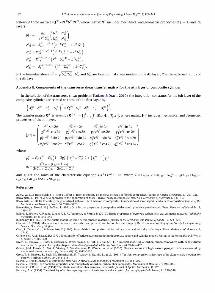
142 I. Tsukrov et al. / International Journal of Engineering Science 58 (2012) 129–143
following three matrices Q(4) = N(4)N(3)N(2), where matrix N(i) includes mechanical and geometric properties of (i � 1) and ithlayers:
NðiÞ ¼ � Ri�1
2kðiÞGðiÞrz
NðiÞ11 NðiÞ12
NðiÞ21 NðiÞ22
!;
NðiÞ11 ¼ �Rkði�1Þ�kðiÞ�1i�1 kði�1ÞGði�1Þ
rz þ kðiÞGðiÞrz
� �;
NðiÞ12 ¼ R�kði�1Þ�kðiÞ�1i�1 kði�1ÞGði�1Þ
rz � kðiÞGðiÞrz
� �;
NðiÞ21 ¼ Rkði�1ÞþkðiÞ�1i�1 kði�1ÞGði�1Þ
rz � kðiÞGðiÞrz
� �;
NðiÞ22 ¼ �R�kði�1ÞþkðiÞ�1i�1 kði�1ÞGði�1Þ
rz þ kðiÞGðiÞrz
� �:
In the formulae above kðiÞ ¼ffiffiffiffiffiffiffiffiffiffiffiffiffiffiffiffiGðiÞhz=GðiÞrz
q; GðiÞhz and GðiÞrz are longitudinal shear moduli of the ith layer; Ri is the external radius of
the ith layer.
Appendix B. Components of the transverse shear transfer matrix for the kth layer of composite cylinder
In the solution of the transverse shear problem (Tsukrov & Drach, 2010), the integration constants for the kth layer of thecomposite cylinder are related to those of the first layer by
AðkÞ1 AðkÞ2 AðkÞ3 AðkÞ4
n oT¼ Q ðkÞ Að1Þ1 Að1Þ2 Að1Þ3 Að1Þ4
n oT;
The transfer matrix Q(k) is given by Q ðkþ1Þ ¼Q2
j¼kþ1 J�1j ðRj�1ÞJj�1ðRj�1Þ
h i, where matrix Ji(r) includes mechanical and geometric
properties of the ith layer:
JiðrÞ ¼
raðiÞ1 sin 2h raðiÞ2 sin 2h raðiÞ3 sin 2h raðiÞ4 sin 2h
gðiÞ1 raðiÞ1 cos 2h gðiÞ2 raðiÞ2 cos 2h gðiÞ3 raðiÞ3 cos 2h gðiÞ4 raðiÞ4 cos 2h
pðiÞ1 raðiÞ1 �1 sin 2h pðiÞ2 raðiÞ2 �1 sin 2h pðiÞ3 raðiÞ3 �1 sin 2h pðiÞ4 raðiÞ4 �1 sin 2h
qðiÞ1 raðiÞ1 �1 cos 2h qðiÞ2 raðiÞ2 �1 cos 2h qðiÞ3 raðiÞ3 �1 cos 2h qðiÞ4 raðiÞ4 �1 cos 2h
0BBBBB@
1CCCCCA;
where
pðiÞj ¼ CðiÞrr aðiÞj þ CðiÞrh 1� 2gðiÞj
� �; qðiÞj ¼ GðiÞrh 2þ aðiÞj � 1
� �gðiÞj
h i;
gi ¼a2
i Crr � ðChh þ 4GrhÞ2ðCrh þ GrhÞai � 2ðChh þ GrhÞ
and ai are the roots of the characteristic equation Da4 + Ea2 + F = 0 where D = CrrGrh, E = 4(Crh + Grh)2 � Crr(4Chh + Grh) �Grh(Chh + 4Grh) and F = 9GrhChh.
References
Avery, W. B., & Herakovich, C. T. (1986). Effect of fiber anisotropy on thermal stresses in fibrous composites. Journal of Applied Mechanics, 53, 751–756.Benveniste, Y. (1987). A new approach to the application of Mori–Tanaka theory in composite materials. Mechanics of Materials, 6, 147–157.Benveniste, Y. (2008). Revisiting the generalized self-consistent scheme in composites: Clarification of some aspects and a new formulation. Journal of the
Mechanics and Physics of Solids, 56, 2984–3002.Benveniste, Y., Dvorak, G. J., & Chen, T. (1991). On effective properties of composites with coated cylindrically orthotropic fibers. Mechanics of Materials, 12,
289–297.Böhlke, T., Jöchen, K., Piat, R., Langhoff, T.-A., Tsukrov, I., & Reznik, B. (2010). Elastic properties of pyrolytic carbon with axisymmetric textures. Technische
Mechanik, 30(4), 343–353.Budiansky, B. (1965). On the elastic moduli of some heterogeneous materials. Journal of the Mechanics and Physics of Solids, 13, 223–227.Chamis, C.C. (1984). Mechanics of composite materials: Past, present, and future. In Proceedings of the 21st annual meeting of the Society for Engineering
Science, Blacksburg, Virginia.Chen, T., Dvorak, G. J., & Benveniste, Y. (1990). Stress fields in composites reinforced by coated cylindrically orthotropic fibers. Mechanics of Materials, 9,
17–32.Christensen, R. M., & Lo, K. H. (1979). Solutions for effective shear properties in three phase sphere and cylinder models. Journal of the Mechanics and Physics
of Solids, 27, 315–330.Drach, B., Tsukrov, I., Gross, T., Dietrich, S., Weidenmann, K., Piat, R., et al. (2011). Numerical modeling of carbon/carbon composites with nanotextured
matrix and 3D pores of irregular shapes. International Journal of Solids and Structures, 48, 2447–2457.Gebert, J.-M., Reznik, B., Piat, R., Viering, B., Weidenmann, K., Wanner, A., et al. (2010). Elastic constants of high-texture pyrolytic carbon measured by
ultrasound phase spectroscopy. Carbon, 48(12), 3647–3650.Gross, T. S., Nguyen, K., Buck, M., Timoshchuk, N., Tsukrov, I., Reznik, B., et al. (2011). Tension–compression anisotropy of in-plane elastic modulus for
pyrolytic carbon. Carbon, 49, 2141–2161.Hashin, Z. (1983). Analysis of composite materials: A survey. Journal of Applied Mechanics, 50, 481–505.Hashin, Z. (1990). Thermoelastic properties and conductivity of carbon/carbon fiber composites. Mechanics of Materials, 8, 293–308.Hashin, Z., & Rosen, B. W. (1964). The elastic moduli of fiber reinforced materials. Journal of Applied Mechanics, 31, 223.Hershey, A. V. (1954). The elasticity of an isotropic aggregate of anisotropic cubic crystals. Journal of Applied Mechanics, 21, 236–240.

I. Tsukrov et al. / International Journal of Engineering Science 58 (2012) 129–143 143
Hervé, E., & Zaoui, A. (1995). Elastic behavior of multiply coated fiber reinforced composites. International Journal of Engineering Science, 33, 1419–1433.Hill, R. (1965). A self-consistent mechanics of composite materials. Journal of the Mechanics and Physics of Solids, 13, 213–222.Honjo, K. (2006). Thermal stresses and effective properties calculated for fiber composites using actual cylindrically-anisotropic properties of interfacial
carbon coating. Carbon, 45, 865–872.Kachanov, M., Tsukrov, I., & Shafiro, B. (1994). Effective moduli of solids with cavities of various shapes. Applied Mechanics Reviews, 47, S151–S174.Kanaun, S. (1975). The method of self-consistent field in the problem of effective elastic properties of composites. Journal of Applied Mechanics and Technical
Physics, 4, 194–203.Kanaun, S. K., & Kudriavtseva, L. T. (1989). Elastic and thermoelastic characteristics of composites reinforced with unidirectional fibre layers. Applied
Mathematics and Mechanics, 53, 628–636.Kanaun, S., & Levin, V. (2008). In Self-consistent methods for composites, Vol. 1, static problems. Solids mechanics and its applications (Vol. 148). Doderecht:
Springer.Kröner, E. (1958). Berechnung der elastischen Konstanten des Vielkristalls aus den Konstanstanten des Einkristalls. Zeitschrift Physik, 151, 504–518.Levin, V. (1976). On the determination of elastic and thermoelastic constants of composite materials. Proceedings of Academic Science USSR, Mechanics and
Solids, 6, 136–145.Levin, V. A., Lokhin, V. V., & Zingerman, K. M. (2000). Effective elastic properties of porous materials with randomly dispersed pores: Finite deformation.
Journal of Applied Mechanics, 67, 667–670.Guigon, M., Ayache, J., Oberlin, A., & Oberlin, M. (1981). Structure and microstructure of some glassy polymers – Carbon fiber composites. Proceedings of 15th
carbon fiber conference (pp. 288). American Carbon Society.McLaughlin, R. (1977). A study of the differential scheme for composite materials. International Journal of Engineering Science, 15, 237–244.Mori, T., & Tanaka, K. (1973). Average stress in matrix and average energy of materials with misfitting inclusions. Acta Metallurgica, 21, 571–574.Papadakis, E. P., & Bernstein, H. (1963). Elastic moduli of pyrolytic graphite. Journal of Acoustic Society of America, 35(4), 521–524.Piat, R. (2010). Personal communication.Piat, R., Tsukrov, I., Böhlke, T., Bronzel, N., Shrinivasa, T., Reznik, B., et al. (2008). Numerical studies of the influence of textural gradients on the local stress
concentrations around fibers in carbon/carbon composites. Communications of Numerical Methods in Engineering, 24, 2194–2205.Reznik, B., Gerthsen, D., Zhang, W., & Hüttinger, K. J. (2003). Texture changes in the matrix of an infiltrated carbon fiber felt studied by polarized light
microscopy and selected area electron diffraction. Carbon, 41(2), 376–380.Salganik, R. L. (1973). Mechanics of bodies with a large number of cracks. Mechanics of Solids, 4, 149–158 (in Russian).Schapery, R. A. (1968). Thermal expansion coefficients of composite materials based on energy principles. Journal of Composite Materials, 2, 380.Sevostianov, I. (2011). On the thermal expansion of composite materials and cross-property connection between thermal expansion and thermal
conductivity. Mechanics of Materials, 45, 20–33.Sevostianov, I., Yilmaz, N., Kushch, V., & Levin, V. (2005). Effective elastic properties of matrix composites with transversely-isotropic phases. International
Journal of Solids and Structures, 42, 455–476.Shavshukov, V., Tashkinov, A., Strzhemechny, Y. M., & Hui, D. (2008). Modelling of pseudoplastic deformation of carbon/carbon composites with a
pyrocarbon matrix. Modelling and Simulations of Material Science and Engineering, 16.Tsukrov, I., & Drach, B. (2010). Elastic deformation of composite cylinders with cylindrically orthotropic layers. International Journal of Solids and Structures,
47, 25–33.Tsukrov, I., Piat, R., Novak, J., & Schnack, E. (2005). Micromechanical modeling of porous carbon/carbon composites. Mechanics of Advanced Materials and
Structures, 12, 43–54.Wagoner, G., & Bacon, R. (1989). Elastic constants and thermal expansion coefficients of various carbon fibers. In Extended abstracts of 19th biennial carbon
conference (pp. 296–297).Zimmerman, R. W. (1985). The effect of microcracks on the elastic moduli of brittle materials. Journal of Material Science Letters, 4, 1457–1460.Zimmerman, R. W. (1991a). Elastic moduli of a solid containing spherical inclusions. Mechanics of Materials, 12, 17–24.Zimmerman, R. W. (1991b). Compressibility of sandstones. Amsterdam: Elsevier.