Embed Size (px)
Citation preview

International Journal of Advance Research in Engineering, Science & Technology(IJAREST),
ISSN(O):2393-9877, ISSN(P): 2394-2444,
Volume 2, Issue 5, May- 2015, Impact Factor: 2.125
All Rights Reserved, @IJAREST-2015
1
Structural Analysis of Formula One Racing Car
Triya Nanalal Vadgama1, Mr. Arpit Patel2, Dr. Dipali Thakkar3, Mr. Jignesh Vala4
Department of Aeronautical Engineering, Sardar Vallabhbhai Patel Institute of Technology, Vasad.
Gujarat Technological University, Ahmedabad, Gujarat, India. 1Student, [email protected]
2Assistant Professor, [email protected]
3Head & Professor, [email protected]
4Assistant Professor, [email protected]
Abstract
A modern Formula One (F1) Racing Car has almost as much in common with an aircraft as it does with an ordinary road
car. Aerodynamics has become a key to success in the sport and teams spend millions of dollars on research and development
in the field each year for improving performance. The aerodynamic designer has two primary concerns:
i. The creation of downforce, to help push the car’s tyres onto the track and improve cornering forces,
ii. To minimise the drag that occurs due to turbulence and acts to slow down the car.
In this project, various features of the car will be enhanced to make the whole car more structurally efficient by analysing
the corresponding structure and forces using Ansys Workbench (Static Structural) software. Structurally efficiency will be
attained by considering the Downforce & Force Reaction, generated at a certain speed, weight, material, strength, and other
performance parameters to achieve the above stated primary concerns.
Keywords – Formula One race car, Airfoil, Angle of Attack (AOA), Force Reaction, Downforce.
I. INTRODUCTION On the surface, automobile racing appears simply
as a popular sport. But in reality, racing serves as a proving
ground for new technology and a battlefield for the giants of
automobile industry. Although human factors are frequently
publicized as the reason behind the success or failure of one
racing team or another, engine power, tire adhesion, chassis
design, and recently, aerodynamics probably play a very
important role in winning this technology race.
Aerodynamics is study of gases in motion. As the principal
application of aerodynamics is the design of aircraft, air is
the gas with which the science is most concerned. Although
aerodynamics is primarily concerned with flight, its
principles are also used in designing automobile. The wind
tunnel is one of the aerodynamicist's basic experimental
tools. However in recent years, it has been supplanted by the
simulation of aerodynamic forces during the computer-aided
design of aircraft and automobiles.
1.1. Work plan
Analysing the magnitude of Downforce over the following
components of the car:
1. Front Wing Airfoil (NACA 4412) & Rear Wing Airfoil
(NACA 2408) :
a) Negative (-150) AOA at free stream velocity of 100
kmph
b) Zero (-00) AOA at free stream velocity of 100 kmph
c) Positive (+150) AOA at free stream velocity of 100
kmph
2. Front Wing Assembly & Rear Wing Assembly :
a) Negative (-150) AOA at free stream velocity of 100
kmph
b) Zero (-00) AOA at free stream velocity of 100 kmph
Refer [1] for the CAD Modelling phase of the project and
[2] for the CFD analysis phase of the project.
1.2. Selection of Airfoil
NACA 4-series airfoils are the most widely used airfoils for
Formula One race cars. The NACA four-digit wing sections
define the profile by:
i. First digit - maximum camber as percentage of the chord.
ii. Second digit - the distance of maximum camber from
the airfoil leading edge in tens of percentage of the chord.
iii. Last two digits - maximum thickness of the airfoil as a
percentage of the chord.
1.2.1. Front Wing Airfoil – NACA 4412
The Front Wing of a Formula One car creates about 25% of
the total car’s downforce. This is one of the most widely
used spoiler airfoil, but needs to be enhanced as per speed.
Such a thicker airfoil is used to obtain the desired higher
downforce from the front end of the car, at a given speed.
Figure 1. NACA 4412
1.2.2. Rear Wing Airfoil – NACA 2408
Due to location of engine at the rear end of the car, more
downforce is generated. Hence, to compensate for
minimization of downforce from rear end, a thinner airfoil is
used. Thinner airfoil also helps to maintain the continuity of
the flow without flow separation. Thus, NACA 2408 is
employed at the rear end.
Figure 2. NACA 2408
1.3 Aerodynamics Background Aerodynamics is a branch of dynamics concerned with
studying the motion of air, particularly when it interacts with

International Journal of Advance Research in Engineering, Science & Technology(IJAREST),
ISSN(O):2393-9877, ISSN(P): 2394-2444,
Volume 2, Issue 5, May- 2015, Impact Factor: 2.125
All Rights Reserved, @IJAREST-2015
2
a moving object. Understanding the motion of air (often
called a flow field) around an object enables the calculation
of forces and moments acting on the object. Typical
properties calculated for a flow field include velocity,
pressure, density and temperature as a function of position
and time. By defining a control volume around the flow
field, equations for the conservation of mass, momentum,
and energy can be defined and used to solve for the
properties. The drag over a body can be minimized by
streamlining it (smooth exterior surface). As a result, there
will be potential improvements in fuel economy. An
inverted airfoil to generate a negative lift force – Downforce.
This leads to major improvements in race car performance,
especially on tracks with numerous high-speed, unbanked
turns. Aerodynamic downforce increases the tires’ cornering
ability by increasing loads on the tires without increasing the
vehicle’s weight. The result is increased cornering ability,
with no weight penalty, which gives a reduction in lap times.
Figure 3. Flow over a Streamlined Body
Figure 4. Aerodynamic Forces
Figure 5. Schematic description of the “Ground Effect”
that increases the aerodynamic lift of the wings when
placed near the ground.
Figure 6. Schematic description of the effect of rear wing
on the streamlines nearby a generic body.
(All photographs are the courtesy of Race Care
Aerodynamics – By Joseph Katz)
II. DOWNFORCE CALCULATION AT
FREESTREAM VELOCITY OF 100 KMPH
USING ANSYS WORKBENCH 14.0 – STATIC
STRUCTURAL
2.1. Front Wing Airfoil (NACA 4412)
2.1.1. Model
The Geometry and Solution is imported from CFX to Static
Structural. Thereafter, the airfoil is meshed as follows:
Patch Conformal Method = Tetrahedrons
Body Sizing = 5 mm
Material Assigned = Structural Steel
Figure 7. Airfoil Mesh for Static Structural
2.1.2. Static Structural Setup
Under the setup, the Pressure Load is imported as Imported
Load for the Fixed Support. 100% of Mechanical nodes are
mapped to the CFD Surface.
Figure 8. Fixed Support (1-face)
2.2. Rear Airfoil (NACA 2408)
2.2.1. Model
The Geometry and Solution is imported from CFX to Static
Structural. Thereafter, the airfoil is meshed as follows:
Patch Conformal Method = Tetrahedrons
Body Sizing = 5 mm
Material Assigned = Structural Steel
Figure 9. Airfoil Mesh for Static Structural
2.2.2. Static Structural Setup
Under the setup, the Pressure Load is imported as Imported
Load for the Fixed Support. 100% of Mechanical nodes are
mapped to the CFD Surface.
Figure 10. Fixed Support (2-faces)
International Journal of Advance Research in Engineering, Science & Technology(IJAREST),
ISSN(O):2393-9877, ISSN(P): 2394-2444,
Volume 2, Issue 5, May- 2015, Impact Factor: 2.125
All Rights Reserved, @IJAREST-2015
3
2.3. Front Wing Assembly (6 Plates of NACA 4412)
2.3.1. Model
The Geometry and Solution is imported from CFX to Static
Structural. Thereafter, the airfoil is meshed as follows:
Patch Conformal Method = Tetrahedrons
Body Sizing = 10 mm
Material Assigned = Structural Steel
Figure 11. Mesh for Static Structural
2.3.2. Static Structural Setup
Under the setup, the Pressure Load is imported as Imported
Load for the Fixed Support. 100% of Mechanical nodes are
mapped to the CFD Surface.
Figure 12. Fixed Support (1-face)
2.4. Rear Wing Assembly (2 Plates of NACA 2408)
2.4.1. Model
The Geometry and Solution is imported from CFX to Static
Structural. Thereafter, the airfoil is meshed as follows:
Patch Conformal Method = Tetrahedrons
Body Sizing = 10 mm
Material Assigned = Structural Steel
Figure 13. Mesh for Static Structural
2.4.2. Static Structural Setup
Under the setup, the Pressure Load is imported as Imported
Load for the Fixed Support. 100% of Mechanical nodes are
mapped to the CFD Surface.
Figure 14. Fixed Support (1-face)
III. RESULTS
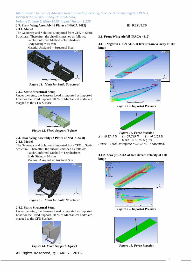
3.1. Front Wing Airfoil (NACA 4412)
3.1.1. Negative (-150) AOA at free stream velocity of 100
kmph
Figure 15. Imported Pressure
Figure 16. Force Reaction
X = -9.1747 N Y = 57.239 N Z = -0.0155 N
TOTAL = 57.97 N (+Y)
Hence, Total Downforce = 57.97 N (–Y Direction)
3.1.2. Zero (00) AOA at free stream velocity of 100
kmph
Figure 17. Imported Pressure
Figure 18. Force Reaction
International Journal of Advance Research in Engineering, Science & Technology(IJAREST),
ISSN(O):2393-9877, ISSN(P): 2394-2444,
Volume 2, Issue 5, May- 2015, Impact Factor: 2.125
All Rights Reserved, @IJAREST-2015
4
X = -0.93611 N Y = 14.411 N Z = 0.00068 N
TOTAL = 14.442 N (+Y)
Hence, Total Downforce = 14.442 N (–Y Direction)
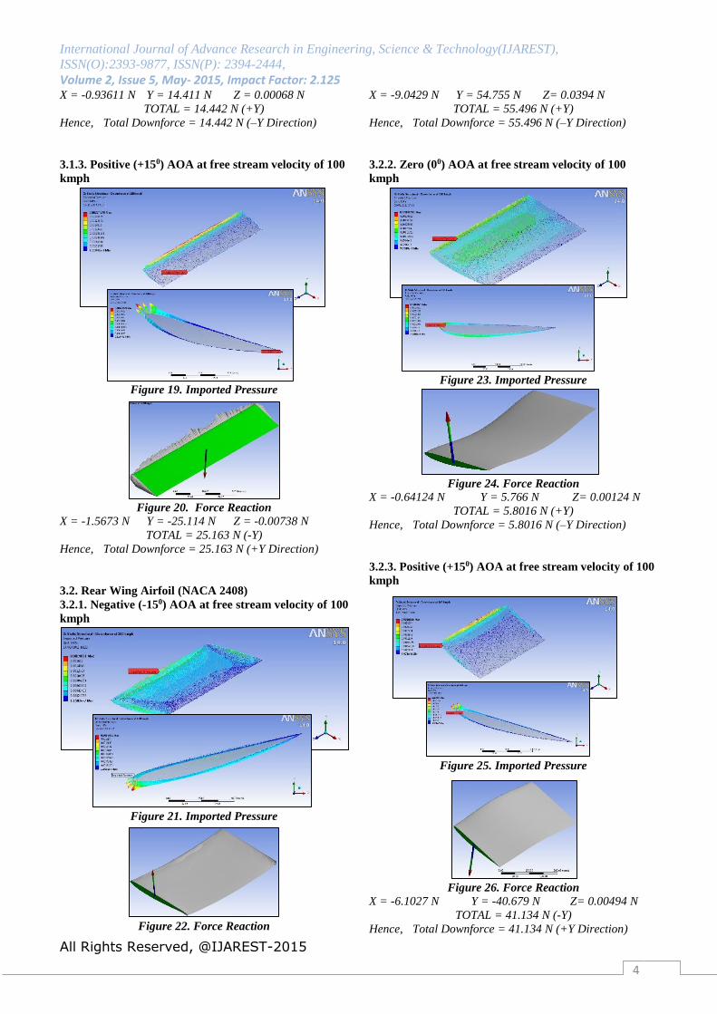
3.1.3. Positive (+150) AOA at free stream velocity of 100
kmph
Figure 19. Imported Pressure
Figure 20. Force Reaction
X = -1.5673 N Y = -25.114 N Z = -0.00738 N
TOTAL = 25.163 N (-Y)
Hence, Total Downforce = 25.163 N (+Y Direction)
3.2. Rear Wing Airfoil (NACA 2408)
3.2.1. Negative (-150) AOA at free stream velocity of 100
kmph
Figure 21. Imported Pressure
Figure 22. Force Reaction
X = -9.0429 N Y = 54.755 N Z= 0.0394 N
TOTAL = 55.496 N (+Y)
Hence, Total Downforce = 55.496 N (–Y Direction)
3.2.2. Zero (00) AOA at free stream velocity of 100
kmph
Figure 23. Imported Pressure
Figure 24. Force Reaction
X = -0.64124 N Y = 5.766 N Z= 0.00124 N
TOTAL = 5.8016 N (+Y)
Hence, Total Downforce = 5.8016 N (–Y Direction)
3.2.3. Positive (+150) AOA at free stream velocity of 100
kmph
Figure 25. Imported Pressure
Figure 26. Force Reaction
X = -6.1027 N Y = -40.679 N Z= 0.00494 N
TOTAL = 41.134 N (-Y)
Hence, Total Downforce = 41.134 N (+Y Direction)
International Journal of Advance Research in Engineering, Science & Technology(IJAREST),
ISSN(O):2393-9877, ISSN(P): 2394-2444,
Volume 2, Issue 5, May- 2015, Impact Factor: 2.125
All Rights Reserved, @IJAREST-2015
5
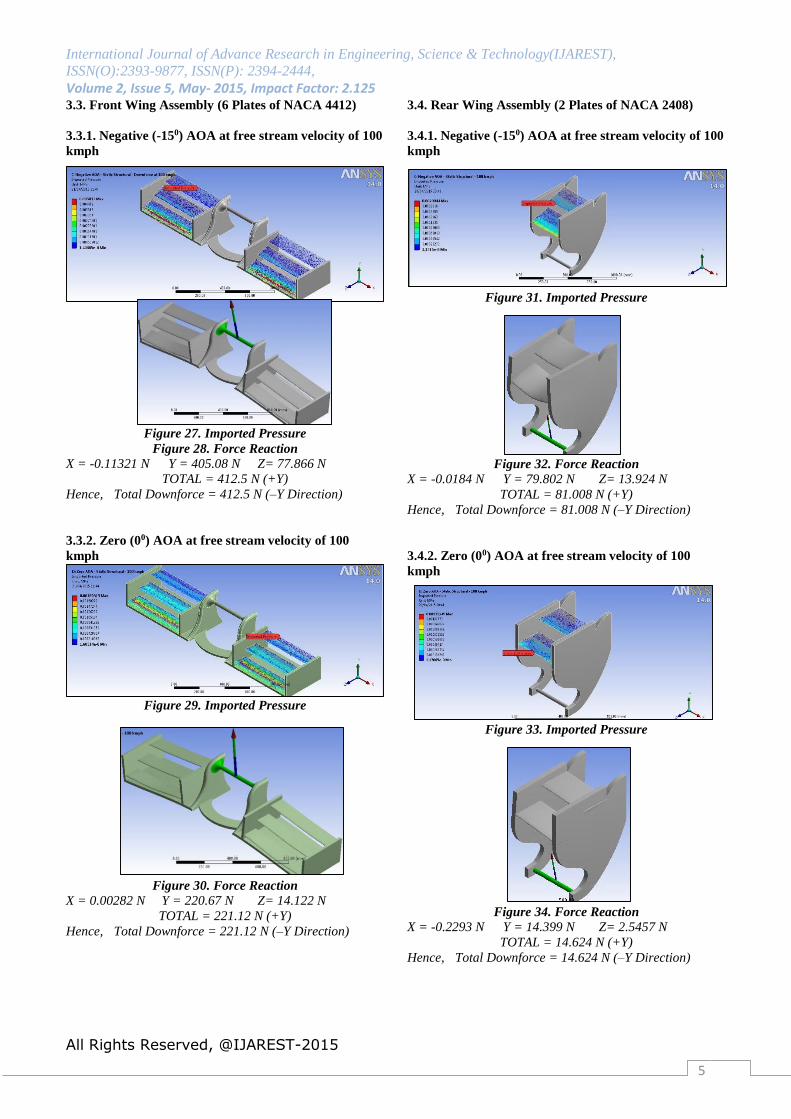
3.3. Front Wing Assembly (6 Plates of NACA 4412)
3.3.1. Negative (-150) AOA at free stream velocity of 100
kmph
Figure 27. Imported Pressure
Figure 28. Force Reaction
X = -0.11321 N Y = 405.08 N Z= 77.866 N
TOTAL = 412.5 N (+Y)
Hence, Total Downforce = 412.5 N (–Y Direction)
3.3.2. Zero (00) AOA at free stream velocity of 100
kmph
Figure 29. Imported Pressure
Figure 30. Force Reaction
X = 0.00282 N Y = 220.67 N Z= 14.122 N
TOTAL = 221.12 N (+Y)
Hence, Total Downforce = 221.12 N (–Y Direction)
3.4. Rear Wing Assembly (2 Plates of NACA 2408)
3.4.1. Negative (-150) AOA at free stream velocity of 100
kmph
Figure 31. Imported Pressure
Figure 32. Force Reaction
X = -0.0184 N Y = 79.802 N Z= 13.924 N
TOTAL = 81.008 N (+Y)
Hence, Total Downforce = 81.008 N (–Y Direction)
3.4.2. Zero (00) AOA at free stream velocity of 100
kmph
Figure 33. Imported Pressure
Figure 34. Force Reaction X = -0.2293 N Y = 14.399 N Z= 2.5457 N
TOTAL = 14.624 N (+Y)
Hence, Total Downforce = 14.624 N (–Y Direction)
International Journal of Advance Research in Engineering, Science & Technology(IJAREST),
ISSN(O):2393-9877, ISSN(P): 2394-2444,
Volume 2, Issue 5, May- 2015, Impact Factor: 2.125
All Rights Reserved, @IJAREST-2015
6
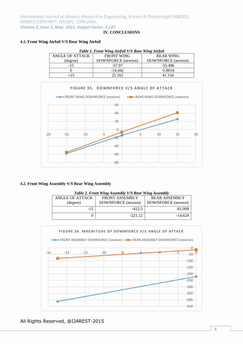
IV. CONCLUSIONS
4.1. Front Wing Airfoil V/S Rear Wing Airfoil
Table 1. Front Wing Airfoil V/S Rear Wing Airfoil
ANGLE OF ATTACK
(degree)
FRONT WING
DOWNFORCE (newton)
REAR WING
DOWNFORCE (newton)
-15 -57.97 -55.496
0 -14.442 -5.8016
+15 25.163 41.134
4.2. Front Wing Assembly V/S Rear Wing Assembly
Table 2. Front Wing Assembly V/S Rear Wing Assembly
ANGLE OF ATTACK
(degree)
FRONT ASSEMBLY
DOWNFORCE (newton)
REAR ASSEMBLY
DOWNFORCE (newton)
-15 -412.5 -81.008
0 -221.12 -14.624
-80
-60
-40
-20
0
20
40
60
-20 -15 -10 -5 0 5 10 15 20
F I G U R E 3 5 . D O W N F O R C E V / S A N G L E O F A T T A C K
FRONT WING DOWNFORCE (newton) REAR WING DOWNFORCE (newton)
-450
-400
-350
-300
-250
-200
-150
-100
-50
0
-16 -14 -12 -10 -8 -6 -4 -2 0
F I G U R E 3 6 . M A G N I T U D E O F D O W N F O R C E V / S A N G L E O F A T T A C K
FRONT ASSEMBLY DOWNFORCE (newton) REAR ASSEMBLY DOWNFORCE (newton)
International Journal of Advance Research in Engineering, Science & Technology(IJAREST),
ISSN(O):2393-9877, ISSN(P): 2394-2444,
Volume 2, Issue 5, May- 2015, Impact Factor: 2.125
All Rights Reserved, @IJAREST-2015
7
Hence, it is concluded that a very high downforce is
created by the Front Wing Assembly as compared to the
Rear Wing Assembly. This is very beneficial to keep the car
on the road and not let it get lifted up in the air during its
travel. Thus, the airfoils very effectively accomplish the
required following results :
i. Front Wing Assembly Downforce must be greater
than that corresponding to the Rear Wing
Assembly. Due to placement of engine at the rear
end of the car, more downforce is already generated
at the rear end & hence a thinner airfoil can be used.
ii. The approximate top speed as read from the
analysis is 330 kmph – A definite race to the finish!
iii. Aerodynamics plays an integrated and essential
role in the racing world.
iv. Such a CFD testing helps to achieve great results
alongwith an appreciable saving in costs.
v. The streamlined body of the car helped to minimize
the drag caused due to turbulence.
vi. The creation of such a significant downforce helps
to push the car’s tyres onto the track.
V. FUTURE SCOPE
i. Computational Fluid Flow and Structural Analysis
of the Car Body Chassis.
ii. Computational Fluid Flow and Structural Analysis
of the Wheels.
iii. Computational Fluid Flow and Structural Analysis
of the entire car model using Supercomputers.
iv. Manufacturing a prototype of the model.
v. Wind Tunnel testing of the model.
vi. Optimization of the Design to achieve higher
speeds and downforce.
ACKNOWLEDGEMENT
It is always a pleasure to remind the fine people who
helped me throughout my project.
I am extremely thankful to Dr. Dipali Thakkar for
giving me an opportunity to undertake this project. I would
like to give a special thanks and express my deep sense of
gratitude to Mr. Arpit Patel for his assistance, expert
guidance, and suggestions throughout this project work.
Without the help of their knowledge and expertise in every
facet of the study, from helping to find the relevant data and
in analyzing the results, this project would not have been
completed. I sincerely thank all other faculty members of the
Aeronautical Department for helping me in all possible ways
for the betterment of my project.
Last, but certainly not the least, I am very thankful to
my family and friends who have been giving me
unconditional support throughout the entire period of my
project, because without them, none of this would have been
possible.
REFERENCES
[1] Triya Nanalal Vadgama, Mr. Arpit Patel, Dr. Dipali
Thakkar, “Design of Formula One Racing Car”,
International Journal of Engineering Research &
Technology (ISSN: 2278-0181), Volume 4, Issue
04, pp. 702-712, April 2015.
[2] Triya Nanalal Vadgama, Mr. Arpit Patel, Dr. Dipali
Thakkar, Mr. Jignesh Vala, “Computational Fluid
Flow Analysis of Formula One Racing Car”,
International Journal for Scientific Research and
Development (ISSN: 2321 0613), Volume 03,
Issue 02, April 2015.
[3] A rear spoiler with adjustable aerodynamic profiles
for a high performance road vehicle (WIPO; Patent
No.: EP2631160; Application No.: 13156647;
Inventor: de Luca Marco; Applicant: Ferrari SPA)
[4] Aerodynamics – by L.J. Clancy
[5] Computational Fluid Dynamics – by J.D. Anderson
[6] Formula One Technical Regulations – FIA
Standards
[7] Fundamentals of Aerodynamics – by J.D.
Anderson
[8] Numerical Investigation of Flow Transition for
NACA-4412 airfoil using Computational Fluid
Dynamics (ISSN: 2319-8753; International Journal
of Innovative Research in Science, Engineering
and Technology - Vol. 2, Issue 7, July 2013)
[9] Race Car Aerodynamics – by Joseph Katz
[10] Study of Front-Body of Formula One Car for
Aerodynamics using CFD (ISSN: 2319-4847;
International Journal of Application or Innovation
in Engineering & Management (IJAIEM) - Volume
3, Issue 3, March 2014).


![International Journal of Advance Research in Engineering ...ijarest.com/papers/finished_papers/150423105927.pdf · [3] Kumar A et al. "Up Gradation of Geometric Design of Sh-131(Ch](https://img.dokumen.tips/doc/110x75/5f1fd4951f315125e6555c12/international-journal-of-advance-research-in-engineering-3-kumar-a-et-al.jpg)