Embed Size (px)
Citation preview

INTERNATIONAL GUIDELINES FOR THE
FIRE PROTECTION OF NUCLEAR POWER PLANTS
ISSUED IN 2015 ON BEHALF OF THE NUCLEAR POOLS’ FORUM
5th EDITION

INTERNATIONAL GUIDELINES FOR THE FIRE PROTECTION OF NUCLEAR POWER PLANTS PUBLISHED ON BEHALF OF THE NUCLEAR POOLS’ FORUM REVISED 5th EDITION 2015 Introductory Note: These Guidelines have been developed by a working group representing nuclear insurers in consultation with fire protection specialists and other technical experts. Due to the importance of achieving the highest possible level of fire protection and prevention at Nuclear Power Stations, they have been approved by the under mentioned members of the Nuclear Pools’ Forum. Belgium Syndicat Belge d'Assurances Nucléaires (SYBAN)
Square de Meeûs 29 B-1000 Brussels e-mail: [email protected]
Belarus Republican Unitary Enterprise “Belarusian National Reinsurance Organization” Belarus Re
14, Chkalov St., Minsk 220039 Republic of Belarus e-mail: [email protected]
Brazil CBRN – Brazilian Pool for the Insurance of Nuclear Risks
IRB Brasil Resseguros S.A. Av. Marechal Câmara 171 - Castelo Rio de Janeiro. RJ – Brasil - CEP 20-020-901 e-mail: [email protected]
Bulgaria Bulgarian National Insurance Nuclear Pool
Energy Ins. Co. Ltd 33 Kn.Al.Dondukov Blvd. 1000 Sofia e-mail: [email protected]
Canada Nuclear Insurance Association of Canada 401 Bay St., Suite 1600 Toronto, Ontario, Canada M5H 2Y4 e-mail: [email protected];[email protected]
China China Nuclear Insurance Pool China Re Building No. 11 Jin Rong Avenue, Xicheng District Beijing 100033 e-mail: [email protected]
Croatia Croatian Nuclear Pool Radnička cesta 40-5 HR - 10000 ZAGREB HRVATSKA/CROATIA E-mail: [email protected]
March 2015 Page 2

Czech Republic Czech Nuclear Insurance Pool c/o Ceska Pojistovna a.s. Na Pankráci 1720 5C/123 140 00 Praha 4 Czech Republic e-mail: [email protected]
France ASSURATOME Tour Franklin, Défense 8 92042 Paris La Défense Cedex e-mail: [email protected]
Germany Deutsche Kernreaktor-Versicherungsgemeinschaft (DKVG) Aachener Str. 75 D-50931 Cologne e-mail: [email protected]
Hungary Hungarian Nuclear Insurance Pool C/o: Allianz Hungária Zrt. 1087 Budapest Könyves K.krt. 48-52 e-mail: [email protected]
Japan The Japan Atomic Energy Insurance Pool Non-Life Insurance Building Annex 9 7, Kanda-Awajicho 2-Chome, Chiyoda-Ku, Tokyo, 101-0063 e-mail: [email protected]
Korea The Korea Atomic Energy Insurance Pool
80, Susong-Dong, Chongno-Gu Seoul 110-733 C/o. Korean Reinsurance Company C.P.O. Box 1438, Seoul (London Liaison Office) International House 1st St. Katherine’s Way, London E1W 1UN e-mail: [email protected]
Mexico Atomic Mexican Pool Reaseguradora Patria, S.A. Periférico Sur No. 2771 Col. San Jerónimo Lidice La Magdalena Contreras México D.F. Mexico e-mail: [email protected]
Netherlands BV Bureau van de Nederlandse Pool voor Verzekering van Atoomrisico’s Visitors’ AddressHandelskade 492288 BA Rijswijk ZH The Netherlands Postal Address Postbus 1074 2280 CB Rijswijk ZH The Netherlands e-mail: [email protected]
March 2015 Page 3
Nordic Nordic Nuclear Insurers Kalevankatu 18A1 FI-00100 Helsinki e-mail: [email protected]
Romania Romanian Pool for the Insurance of Atomic Risks c/o Generali Asigurari S.A. Str Ghe. Polizu 58 – 60 Sector 1 Bucharest 011062 e-mail: [email protected]
Russia Russian Nuclear Insurance Pool 9/8 Building 2, 3 Floor, Maly Gnezdnikovsky per., Moscow, Russian Federation, 125009 e-mail: [email protected]
Slovakia Slovak Nuclear Insurance Pool Allianz-Slovenská poistovna, a.s. Dostojevského rad 4 815 74 Bratislava 1 Slovak Republic e-mail: [email protected]
Slovenia Nuclear Insurance and Reinsurance Pool (Nuclear Pool) Miklosiceva 19 SL-1000 Ljubljana e-mail: [email protected]
South Africa South African Pool for the Insurance of Nuclear Risks c/o The South African Insurance Association JCC House 3rd Floor 27 Owl Street Milpark 2029 Postal AddressP.O. Box 30619 Braamfontein, 2017 e-mail: [email protected], [email protected]
Spain Espanuclear Aseguradores de Riesgos Nucleares, A.I.E. Sagasta, 18– 4o derecha 28004 Madrid e-mail: [email protected]
Sweden Nordic Nuclear Insurers
Birger Jarlsgatan 57B S-11396 Stockholm e-mail: [email protected]
Switzerland Swiss Pool for the Insurance of Nuclear Risks Mythenquai 50/60 CH-8022 Zurich e-mail: [email protected]
March 2015 Page 4

Taiwan Nuclear Energy Insurance Pool of the Republic of China
15F, 88, Nanking East Road, Sec. 2 Taipei, 104 e-mail: [email protected]
Ukraine Nuclear Insurance Pool
Vul. M. Raskovoy, 11 Office 620 Kiev 02660 e-mail: [email protected]
United Kingdom Nuclear Risk Insurers Limited
18 St. Swithin’s Lane, London EC4N 8AD, UK e-mail: [email protected]
United States American Nuclear Insurers (ANI)
95 Glastonbury Blvd., Suite 300 Glastonbury, Connecticut 06033 4453 e-mail: [email protected]
March 2015 Page 5
Disclaimers of liability concerning the use of The International Guidelines for the Fire Protection of Nuclear Power Plants document. The members of the Nuclear Pools’ Forum make no claims, promises, guarantees or warrantees as to the accuracy, completeness or adequacy of any information published in The International Guidelines for the Fire Protection of Nuclear Power Plants. The members of the Nuclear Pools’ Forum disclaim liability for any personal injury, damage to property or other damages of any nature whatsoever, whether special, indirect, consequential or compensatory, directly or indirectly resulting from the publication, use of, or reliance on The International Guidelines for the Fire Protection of Nuclear Power Plants. Anyone using The International Guidelines for the Fire Protection of Nuclear Power Plants should rely on his or her own independent judgment or, as appropriate, seek the advice of a competent professional in determining the exercise of reasonable care in any given circumstance. Reproduction in whole or in part permitted with indication of source.
March 2015 Page 6

Table of Contents Chapter 1 – Fire Protection Program ............................................................................................... 12
1-1 Organisation and Management ................................................................................................ 12 1-2 Administrative Controls ........................................................................................................... 13 1-3 Fire Hazards Analysis (FHA) ................................................................................................... 15
1-3.1 Purpose .......................................................................................................................... 15 1-3.2 Scope ............................................................................................................................. 15 1-3.3 Application of Results ................................................................................................... 16 1-3.4 Maintaining the Fire Hazards Analysis ......................................................................... 16
1-4 Pre-Fire Plans ........................................................................................................................... 16 1-5 Quality Assurance .................................................................................................................... 16
Chapter 2 – General Plant Design .................................................................................................... 17 2-1 General ..................................................................................................................................... 17 2-2 Building Construction .............................................................................................................. 17 2-3 Fire Load of Buildings ............................................................................................................. 17 2-4 Separation of Plant Areas and Equipment ............................................................................... 18 2-5 Protection of Openings in Fire Barriers ................................................................................... 19
2-5.1 General .......................................................................................................................... 19 2-5.2 Door Openings .............................................................................................................. 19 2-5.3 Cable and Conduit Penetrations .................................................................................... 20 2-5.4 Pipe Penetrations ........................................................................................................... 20 2-5.5 Ventilation Ducts .......................................................................................................... 20 2-5.6 Joints ............................................................................................................................. 20
2-6 Smoke Ventilation ................................................................................................................... 20 2-7 Emergency Lighting ................................................................................................................. 21
2-7.1 Emergency Ordinary Lighting ...................................................................................... 21 2-7.2 High Intensity Discharge Lighting................................................................................ 21
2-8 Curbing and Drainage .............................................................................................................. 21 Chapter 3 – Fire Protection Systems and Equipment ...................................................................... 22
3-1 General ..................................................................................................................................... 22 3-2 Fire Detection and Signalling Systems .................................................................................... 22 3-3 Fire Suppression Systems ........................................................................................................ 23
3-3.1 General .......................................................................................................................... 23 3-3.2 Water Based Systems .................................................................................................... 23 3-3.3 Gaseous Based Systems ................................................................................................ 23
3-4 Water Supply ........................................................................................................................... 24 3-5 Valve Supervision .................................................................................................................... 25 3-6 Fire Main, Hydrants and Building Standpipes ......................................................................... 25 3-7 Fire Extinguishers .................................................................................................................... 26
Chapter 4 – Station Fire Brigade...................................................................................................... 27 4-1 Organisation ............................................................................................................................. 27 4-2 Training and Drills ................................................................................................................... 27 4-3 Communications ...................................................................................................................... 28 4-4 Liason with External Emergency Organisations ...................................................................... 28 4-5 Station Fire Brigade Equipment ............................................................................................... 29
Chapter 5 – Specific Consideration for Nuclear Risks .................................................................... 29 5-1 Specific Consideration for Nuclear Risks ................................................................................ 29 5-2 Nuclear Reactor Safety Considerations ................................................................................... 30
5-2.1 Fire Analyses ................................................................................................................ 30 5-2.2 Safe Shutdown Systems and Equipment ....................................................................... 30
5-3 Radtioation and Radioactive Contamination Considerations .................................................. 31 5-3.1 Radioactive Contamination ........................................................................................... 31
March 2015 Page 7

5-3.2 Restrictions to Firefighting ........................................................................................... 31 Chapter 6 – Specific Fire Protection Guidelines ............................................................................. 31
6-1 Reactor Containment ............................................................................................................... 31 6-2 Turbine Building ...................................................................................................................... 32
6-2.1 General .......................................................................................................................... 32 6-2.2 Oil Piping ...................................................................................................................... 33 6-2.3 Nonporous Insulation .................................................................................................... 33 6-2.4 Turbine and Generator Bearings and Oil Piping........................................................... 33 6-2.5 Shaft Driven Generator Exciter .................................................................................... 34 6-2.6 Below the Turbine-Generator Group ............................................................................ 34 6-2.7 Oil Storage Tanks, Reservoirs and Purifiers ................................................................. 34 6-2.8 Oil Containment ............................................................................................................ 35 6-2.9 Auxiliary Turbines, Large Pumps and Motors ............................................................. 35 6-2.10 Hydrogen Systems ...................................................................................................... 35 6-2.11 Hydrogen Seal Oil Systems ........................................................................................ 35 6-2.12 Hydraulic Control Systems ......................................................................................... 36 6-2.13 Smoke and Heat Venting ............................................................................................ 36
6-3 Electrical Equipment ................................................................................................................ 36 6-3.1 General .......................................................................................................................... 36 6-3.2 Specific Equipment ....................................................................................................... 36
6-3.2.1 Fluid Filled Transformers .................................................................................... 36 6-3.2.2 Polychlorinated Biphenyls (PCB’S) .................................................................... 37 6-3.2.3 Dry Transformers ................................................................................................. 37 6-3.2.4 Switchgear ............................................................................................................ 37 6-3.2.5 Power Cables ....................................................................................................... 37 6-3.2.6 Controls and Relays ............................................................................................. 38 6-3.2.7 Battery rooms ....................................................................................................... 38 6-3.2.8 Computer and Communication Rooms ................................................................ 38
6-3.3 Lightning Protection ..................................................................................................... 39 6-3.3.1 Design Principles ................................................................................................. 39 6-3.3.2 Maintenance for Lightning Protection ................................................................. 39
6-3.4 Maintenance for Electrical Equipment ......................................................................... 39 6-3.5 Firefighting Involving Electrical Equipment ................................................................ 39
6-4 Control Buildings ..................................................................................................................... 39 6-5 Concentrated Electrical Cable .................................................................................................. 40
6-5.1 Fire Hazard .................................................................................................................... 40 6-5.2 Fire Protection ............................................................................................................... 40
6-6 Miscellaneous Areas ................................................................................................................ 41 6-6.1 Engine Driven Emergency Power Supplies .................................................................. 41
6-6.1.1 Fire Hazard ............................................................................................................ 41 6-6.1.2 Fire Protection ....................................................................................................... 41
6-6.2 Warehousing ................................................................................................................. 42 6-6.2.1 Fire Hazard ............................................................................................................ 42 6-6.2.2 Storage Arrangement ............................................................................................. 42 6-6.2.3 Fire Protection ....................................................................................................... 42
6-6.3 Office Buildings ............................................................................................................ 42 6-6.4 New Fuel Area .............................................................................................................. 42 6-6.5 Water Cooling Towers .................................................................................................. 43
6-6.5.1 Fire Hazard ............................................................................................................. 43 6-6.5.2 Fire Prevention ....................................................................................................... 43 6-6.5.3 Fire Protection ........................................................................................................ 43
6-6.6 Auxiliary Boilers ........................................................................................................... 43 6-6.7 Training Simulators ...................................................................................................... 43
March 2015 Page 8
6-6.8 Overhead and Gantry Cranes ........................................................................................ 43 6-6.9 Laboratories .................................................................................................................. 44
Chapter 7 – New Build ...................................................................................................................... 44 7-1. General ................................................................................................................................. 44
Chapter 8 – Decommissioning and Shutdown ................................................................................. 45 8-1 General ..................................................................................................................................... 45
Chapter 9 – Fire Protection System Inspection, Testing and Maintenance ................................... 45 9-1 General. .................................................................................................................................... 45
Definitions and Acronyms................................................................................................................. 47 Appendix A – Explanatory Information ........................................................................................... 50 Appendix B – General Background on Turbine-Generator Oil Hazards ....................................... 55 Appendix C – Relevant Publications on Fire Protection of Nuclear Power Plants ....................... 57
March 2015 Page 9

Preface to the Fifth Edition The first edition of the International Guidelines for the Fire Protection of Nuclear Power Plants was published in 1974 by an International Working Party representing nuclear insurance pools from many countries. The Guidelines evoked considerable interest among international nuclear power plant fire protection specialists, and in many countries this original edition served as a model for the development of national regulations and prescriptions for fire protection in nuclear power plants. A second and third edition developed in 1983 and 1997 respectively incorporated a number of important additions such as lessons learned from loss experience, and knowledge obtained by insurance pool engineers in the course of their on-site technical inspections. Furthermore, these editions, took into account the new knowledge acquired, for example, the phase out of Halon as an acceptable extinguishing agent, changes in the treatment of PCB’s (polychlorinated biphenyls) in transformers and circuit breakers and surveillance testing of fire protection equipment. The fourth edition was incorporate new technology and the inspection experience of pool engineers since 1997. Performance-based methods to analyze fire risk have been introduced since the third edition, and this technology was applied. Also, inspection experience has shown that many of the prescriptive elements of the third edition were difficult to apply in older plants. This edition recognizes that performance-based technology can offer acceptable solutions to fire risk problems when recognised technology is properly used and implemented. Many of the prescriptive recommendations of the third edition were removed in this edition to allow for the use of performance-based technology. Included in the fifth edition, as well as in the fourth edition, of these Guidelines are topics and issues that are often not fully considered by national authorities’ regulations but have proven to be important to operators and insurers alike. Nuclear Regulatory Authorities consider fires but, generally, only from the standpoint of their effects on nuclear safety. The Pools’ insured experience demonstrates that major fires can occur in the conventional areas of nuclear plants; most do not prejudice nuclear safety, but all can have significant economic impact on the nuclear power plant operator’s financial status. Property damage can cost substantial amounts, and forced outages of a year or even longer can result in very large loss of generating revenue. In line with past editions of the Guidelines, the recommendations contained in this edition are intended for those types of nuclear stations equipped with Light Water Reactors, Heavy Water Reactors, and Gas-Cooled Reactors. The use of liquid sodium in Fast Breeder Reactors is not specifically addressed. Many of the recommendations contained in these Guidelines, however, will find application in Fast Breeder Reactor systems. Today’s pool engineers are being called upon most frequently to perform technical evaluations of operating reactors already insured or those located in parts of the world that heretofore have not been insured or reinsured by the pools. The focus of the fourth edition was to develop an up-to-date documented basis for inspections and recommendations when the pools’ engineers evaluate nuclear power plants and to provide a succinct and useful mechanism to convey the pools’ positions on fire protection. The Pools intend that each plant be evaluated against the “best practices” standards described in the Guidelines, taking into consideration relevant site specific approaches. This fifth edition of the International Guidelines for the Fire Protection of Nuclear Power Plants is intended to reflect the status of the worldwide nuclear power industry and to offer guidance on the best current standards of fire prevention and protection for nuclear insurance risk assessments and
March 2015 Page 10

engineering inspections. Where adopted, they should lead to improvements in fire protection both at plants that are currently insured and those seeking nuclear insurance for the first time. Appendix A complements sections of the main text marked with an * with more detailed explanatory information including in some cases quantitative information. Appendix B describes the turbine-generator group fire risk. Appendix C lists relevant organisations and documents related to fire protection in nuclear power plants.
March 2015 Page 11

Chapter 1 – Fire Protection Program
1-1 ORGANISATION AND MANAGEMENT 1-1.1 A fire protection program should be provided at each nuclear power station. The program should be based on a written fire protection plan. The plan should document management’s fire protection program policy and goals. All the policies, programs and procedures that go together to form the fire protection program should be listed in the plan. Responsibility for implementing all aspects of the plan should be clearly defined.
1-1.2 The fire protection program should have the following fundamental goals:
1-1.3 The organisational responsibilities and lines of communication for fire protection should be defined through the use of organizational charts and functional descriptions of each position’s responsibilities. The following should be defined:
1. The management position that has overall responsibility for the formulation, implementation and assessment of the effectiveness of the station fire protection program.
2. The management position(s) directly responsible for implementing and periodically assessing the effectiveness of the station’s fire protection program. Results of assessments and recommendations for improvement should be formally reported on a regularly scheduled basis to the management position cited above.
3. The management position (fire protection program manager) directly responsible for the day-to-day implementation of the fire protection program.
4. The position responsible for fire protection quality assurance through independent inspections, audits and follow-up corrective actions.
5. The station fire brigade.
1-1.4 Responsibilities for the following should be assigned:
1. Perform periodic inspections to: identify transient combustibles and ignition sources, evaluate housekeeping practices, assure the availability and readiness of all fire protection systems/equipment both active and passive, and ensure that corrective actions for identified deficiencies in the fire protection program are carried out in a prompt and effective manner.
2. Provide firefighting training for station personnel.
3. Design, select and modify firefighting systems and equipment.
4. Inspect and test fire protection equipment.
5. Evaluate test and inspection results of fire protection equipment.
6. Prepare critiques of fire drills to determine how well training objectives are being met.
1. to prevent fires from starting and spreading,
2. to rapidly detect, control and extinguish those fires that do occur,
3. to provide adequate protection to structures, systems, and components important to nuclear safety so that in the event of a fire, safe shutdown of the reactor can be achieved,
4. to provide reasonable assurance that the fire event will not result in an unacceptable radiological release and
5. to provide reasonable assurance that the fire event will not cause unacceptable economic consequences.
March 2015 Page 12

7. Review proposed work activities, including hot work, from a fire safety perspective.
8. Train contractors in appropriate procedures and practices that implement the station’s fire protection program.
9. Manage fire protection impairments.
1-1.5 Minimum qualifications should be established for key positions within the organization:
1. The fire protection program manager should be or have on staff a fire protection engineer.
2. The fire brigade members should satisfactorily complete the fire brigade training described in Section 4-2.
3. The personnel responsible for maintenance, testing and inspection of fire protection systems and equipment should be qualified for such work by training and experience.
4. The personnel responsible for the training of the fire brigade should be qualified for such work by training and experience.
1-2 ADMINISTRATIVE CONTROLS Administrative controls should be established to minimize fire hazards throughout the station. The controls should take into account the results of the Fire Safe Shutdown Analysis (FSSA) as those controls may be more restrictive in FSSA areas:
1-2.1 Station inspections:
1. Walk-through inspections should be conducted to measure performance of administrative controls.
2. The inspection frequency should be sufficient to ensure administrative controls are effective. The frequency should be increased during major maintenance operations.
3. The results of walk-through inspections should be documented and deficiencies should be corrected promptly.
4. The inspection frequency should be reviewed and amended based on the performance demonstrated during walk-through inspections.
5. There should be resources dedicated for the inspections.
1-2.2 Plant administrative procedures should specify requirements governing the storage, use and handling of combustible materials.
1. A maximum allowable inventory of flammable and combustible material should be established for each fire compartment based on the Fire Hazards Analysis (see Section 1-3).
2. Procedures should be established for the storage, transport and use of hydrogen and other flammable gases.
3. Procedures should be established for the storage, transport and use of flammable and combustible liquids.
4. Procedures should be established for the storage, transport and use of oxidizing liquids and gases.
5. Only non-combustible or approved flame retardant tarpaulins should be used. Use of halogenated plastics should be minimized.
6. The use of wood should be minimized. Metal scaffolding is preferred. When wood is used, it should be approved pressure-impregnated, fire-retardant lumber.
March 2015 Page 13

7. All interior temporary structures should be constructed of non-combustible or limited combustible material and protected by a fire detection/suppression system unless the Fire Hazards Analysis determines that such a system is not required.
8. Compensatory measures should be taken if established limits for combustible materials are temporarily exceeded.
9. Procedures should be established for the inspection of thermal insulating materials to ensure their integrity with respect to fire protection goals.
10. A written procedure should be established to address control for laydown areas and temporary storage facilities.
1-2.3 Housekeeping should be maintained at a high level to minimize the fire risk. Accumulations of combustible waste material should be removed from the station at the end of the work activity or the end of the shift, whichever comes first.
1-2.4 Plant administrative procedures should address the control of ignition sources.
1-2.4.1* A welding and cutting procedure should be implemented. Written permission from the fire protection program manager or other fire protection specialists should be obtained before starting activities involving cutting, welding, grinding or other potential ignition sources. Permission should not be granted until:
1. an inspection of the hot work area has been conducted,
2. combustibles within 10 m (33 ft), at a minimum, have been moved away or safely covered,
3. it has been confirmed that the atmosphere is free of combustible gas,
4. all cracks or floor openings have been closed or covered and
5. a trained fire watch (with appropriate equipment) has been assigned for both the work period and post work period.
1-2.5 Smoking should only be permitted in designated external well-appointed fire safe areas out of buildings.
1-2.6 The use of temporary electrical wiring should be minimized. The integrity of temporary wiring, while in use, should be periodically monitored. If temporary electrical wirings required, a permanent solution for the temporary wiring should be implemented as soon as possible.
1-2.7 Plant administrative procedures should address the use of electrical portable appliances and equipment. The equipment should be examined at periodic intervals, i.e. the portable appliances are to be tested to ensure that the degree of protection remains adequate.
1-2.8 Only approved heating devices (both fixed and temporary) should be used. Portable heaters should be equipped with a tip over device to shut off the heater if it is not in the upright position.
1-2.9 Open-flame or combustion-generated smoke should not be used for leakage testing.
1-2.10 A written procedure should be established to address impairments to fire protection systems and features and to other plant systems that directly impact fire risk (e.g., ventilation systems, plant emergency communication systems, egress and access routes, passive systems such as barriers). This procedure should include identification of impaired systems, notifications (e.g., plant operations, station fire brigade, external agencies) and provision for compensatory measures (including restricted station activities).
1. The duration of impairments to fire protection systems should be managed to be as short as possible.
2. Appropriate post-impairment testing should be performed to ensure that the system will function as intended.
March 2015 Page 14

1-2.11 Fire protection systems remain in stand-by for long periods and then are expected to perform as designed during a fire event. Performance and reliability of fire protection systems depend on the inspection, testing and maintenance these systems receive. A program should be provided to ensure that all fire protection systems, including passive systems, are inspected, tested and maintained as follows:
1. Testing and inspection should be performed in accordance with recognised standards, manufacturers’ recommendations and written plant procedures. Results of tests and inspections should be documented. Where performance-based approaches are used to reduce inspection and testing frequencies, the analysis to determine the changed frequency shall be documented. When performance-based results indicate performance is deteriorating, the program shall revert to timeframes recommended by recognised standards and manufacturers’ recommendations.
2. Inspection and testing procedures should address system aging. Performance tests of fire pumps and fire mains should be conducted to demonstrate flow and pressure design requirements are being met. Fire sprinkler systems should be inspected for the presence of foreign material, pinhole leaks, and/or obstructed strainers. Other suppression and detection systems should be evaluated based on performance and obsolescence. Passive systems should be inspected for signs of damage due to aging.
3. Follow-up actions and correction of deficiencies detected during testing and inspection should be performed promptly and documented.
1-3 *FIRE HAZARDS ANALYSIS (FHA)
1-3.1 Purpose A FHA is performed to evaluate the potential fire hazards and appropriate fire protection systems and features used to mitigate the fire hazards.
1-3.2 Scope The FHA should cover all relevant areas of the plant to clearly demonstrate there is a sufficient level of protection to meet the goals listed in 1-1.2. It should be performed by qualified fire protection and reactor systems engineers and include the following:
1. The evaluation of physical construction and layout of buildings and equipment (including electrical cables) within fire compartments or fire cells.
2. An inventory of combustibles, including maximum transient combustibles within each fire compartment or cell.
3. A description of fire protection equipment, including detection systems and manual and automatic extinguishing systems in each fire compartment or cell.
4. An analysis to assure a single fire event (in any compartment or cell) cannot impair required safe shutdown functions or result in the uncontrolled release of radioactive contamination to the environment. The analysis should use recognised technology as a basis for conclusions with consideration given to:
1. fire growth and heat released from a realistic conservative design basis fire, 2. the effects of fire on pieces of equipment,
3. the impact of random equipment failures and human errors, and
4. the potential adverse effect operating fire suppression systems can have on safe shutdown functions.
5. An analysis of irradiated fuel storage areas and storage areas for radioactive materials.
March 2015 Page 15

1-3.3 Application of Results Where results of the FHA show that the goals listed in Section 1-1.2 cannot be achieved, modifications, actions and control measures should be undertaken promptly to reduce the fire risk to an acceptable level {as low as reasonably practicable (ALARP)}.
1-3.4 Maintaining the Fire Hazards Analysis 1-3.4.1* Once the FHA has been completed and responsibility assigned for its maintenance, it is important to ensure that the integrity of the fire protection measures put into place are not compromised.
1. Subsequent plant modification proposals should be evaluated for their impact on the FHA.
2. Administrative controls should be in place to assure that combustibles, including transient combustibles and ignition sources, do not build up to a level invalidating the analysis.
3. The FHA should be reviewed annually.
1-4 PRE-FIRE PLANS 1-4.1 Detailed pre-fire plans should be developed for all areas in which a fire could jeopardize safe shutdown, cause an unacceptable radiological release or economic consequences.
1. The plans should include details of the fire compartment layout, fire hazards, safety related components and any fire protection features that may be present. Impairment information should be appended to appropriate pre-fire plans.
2. Plans should include strategies for:
1. response to fire alarms,
2. notification of emergency response teams (e.g., station fire brigade, off-site fire department),
3. coordination with operations and security personnel,
4. firefighting techniques and
5. response to potential radiological hazards,
6. other potential hazards (e.g., electrical, chemical).
1-4.2 Pre-fire plans should be available in the Main Control Room (MCR) and to the Station Fire Brigade.
1-4.3 Plans should be reviewed and revised when conditions change. A complete review should be conducted periodically.
1-5 QUALITY ASSURANCE 1-5.1 The Quality Assurance (QA) program should have requirements for the following aspects of the fire protection program:
1. design and procurement control,
2. instructions, procedures and drawings,
3. control of purchased material, equipment and services,
4. inspections,
5. test and test control,
6. inspection, test and operating status,
7. nonconforming items,
March 2015 Page 16

8. corrective action,
9. records,
10. audits and
11. training.
1-5.2 A written procedure should be established to address compliance management with the administrative controls and implementation of QA criteria, including design and procurement documents, instructions, procedures, drawings, and inspection and test activities as they apply to fire protection features and safe-shutdown capability. In particular, controls should be established to:
1. Ensure the design basis document shall remain up to date as a controlled document; and,
2. Changes affecting the design, operation or maintenance of the plant shall be reviewed to determine any potential impact on the fire protection documentation and processes.
Chapter 2 – General Plant Design
2-1 GENERAL 2-1.1 To prevent the spread of fires and to assist in fire-fighting, structural fire protection measures should be established. These include requirements that support fire protection related to:
1. building materials and construction,
2. formation of fire compartments and fire cells,
3. provision for smoke ventilation or smoke control installations and
4. escape and access routes.
2-1.2 Spatial fire separation of buildings as well as requirements for firefighting should be considered when planning the layout of the buildings of a nuclear power plant. Access roads and deployment areas for the emergency responders should be provided. Entry points to buildings should be readily identifiable to the emergency responders.
2-1.3 In the case of a building fitted with dry fire mains, there should be a clear sign at the inlet stating that it is an inlet for fire water and what pressure can be used.
2-2 BUILDING CONSTRUCTION 1. In general building construction should be non-combustible.
2. Steel frames (e.g., the turbine hall) should be protected to increase their fire resistance. Where steel frames are not protected, the configuration should be justified by the FHA.
3. As far as practicable, the roof construction of all buildings should be designed to reduce the risk of collapse in case of a fire.
4. Roof construction should be designed and installed so it will not contribute fuel to a fire inside the building. Flame spread on the exterior covering should be limited. Roof construction should be analysed in the FHA.
2-3 FIRE LOAD OF BUILDINGS 1. The quantity and use of plastics should not exceed the scope and limits specified in the FHA
for each fire compartment. In particular, this applies to areas of high value electric and electronic instruments and control installations (e.g. computer room, control room).
2. Floor coverings should be non-combustible. If this is not feasible, the floor covering material should not be readily ignitable, with low flame spread characteristics. The floor
March 2015 Page 17

covering should be tested for surface flammability and approved to a National or International standard and be analysed in the FHA.
3. Raised floors, suspended ceilings and their load-bearing construction should be of noncombustible materials. The fire loads, both in raised floors and above suspended ceilings, should be kept as low as practicable.
4. All building insulation and covering, including clips and fasteners, should be noncombustible.
5. Partitions, fittings, furniture, etc. should be non-combustible as far as practicable.
6. Heating and ventilation ducts and drain piping should be made from non-combustible materials. Large ventilation filter systems should be analysed in the FHA.
7. Cable installations require detailed fire protection planning in advance of actual installation (see Section 6-5).
8. Fire load from coatings for walls, ceilings and floors should be minimized as far as practicable.
9. Fire load in buildings containing nuclear fuel and nuclear waste should be minimized as far as practicable.
10. Thermal insulation materials, radiation shielding materials, ventilation duct materials and sound proofing materials shall be noncombustible or approved to a National or International standard.
2-4 SEPARATION OF PLANT AREAS AND EQUIPMENT 2-4.1* The plant should be subdivided into individual fire compartments and fire cells to reduce not only the risk of fire spread, but also the consequential damage arising from corrosive gases, smoke and radioactive contamination. Fire resistance requirements are related to integrity, insulation and for load bearing elements, load bearing capacity.
2-4.2 Each of the following buildings should be an independent fire compartment: 1. the reactor building,
2. the turbine building,
3. the electrical equipment building,
4. the auxiliary systems building and
5. radioactive waste buildings.
2-4.3 In addition, the following areas should be separated by rated fire barriers:
1. each unit of a multi-unit power plant including their MCRs and turbine generators.
2. the reactor containment inside the reactor building (if distinct from the latter),
3. turbine-generator group oil-conditioning room (e.g., coolers, filters, valves, pumps),
4. turbine-generator group oil reservoir and associated installations,
5. emergency diesel generator rooms,
6. fuel tanks and storage and
7. Emergency Control Area (ECA) and adjoining rooms.
If not in full compliance with requirements on separation, the situation should be analysed and alternative measures such as fixed automatic extinguishing systems should be provided.
March 2015 Page 18

2-4.4 The buildings and areas described in 2-4.2 and 2-4.3 should be subdivided into smaller individual fire compartments or fire cells with consideration for operational requirements, including complying with redundancy requirements for nuclear safety.
2-4.5 The following rooms should form individual fire compartments surrounded by rated fire barriers:
1. MCR and its annexes,
2. computer rooms,
3. electrical switchgear rooms,
4. cable distribution rooms and basements, 5. auxiliary power supply installations,
6. battery room (emergency power supply installation),
7. boilers and
8. firewater pump rooms.
2-4.6 Redundant (multiple) safe shutdown functions, including associated cables for power supply, controls and instrumentation should be separated by fire barriers where possible. When fire barriers are not possible, redundant functions should be located in different fire cells as determined by the FHA. 2-4.7 Ducts and shafts for cables, pipes and ventilation that cross fire compartments and fire cells should be designed to prevent the spread of fire and smoke between compartments and cells.
2-4.8 Fire compartments consisting of cable and pipe tunnels should be subdivided by fire barriers into sections of not more than 50 m (165 ft) length.
2-4.9 Buildings such as stores, workshops, pump house, water intake, administration, and canteens should be separated from production areas.
2-5 PROTECTION OF OPENINGS IN FIRE BARRIERS
2-5.1 General 1. Fire compartments require specific preventive measures at openings in fire barriers. The
fire resistance rating of fire door assemblies, fire dampers, penetration seals, etc., should be consistent with that of the fire barrier.
2. If additional considerations (e.g., radiation protection, mechanical strength, security) reduce the fire resistance of these openings, other fire protection features should be provided to compensate for the reduction in fire resistance.
3. Fire doors, dampers, seals, etc. should be subject to inspections and tests as required by recognised standards and / or manufacturers’ recommendations.
2-5.2 Door Openings 1. All doors in fire barrier walls should be approved fire doors.
2. Each fire door should be identified and marked.
3. Fire doors should always be closed. When required to be kept open, hold-open devices should be installed to automatically release the door as required by the FHA or the door should be declared inoperable with mitigating action taken as required by plant procedures.
March 2015 Page 19
2-5.3 Cable and Conduit Penetrations 1. Openings in a fire barrier for cables or conduits should be sealed with devices having a fire
resistance rating consistent with the fire barrier. The penetrations and sealing compounds or blocks should satisfy both the integrity and insulation requirements and be approved to a National or International standard.
2. Subsequent installation of cables or conduits should not reduce the fire resistance of the fire barrier.
3. Cable trays should be designed to avoid reducing fire resistance of cable penetrations.
4. Each cable or conduit penetration should be identified and marked.
2-5.4 Pipe Penetrations 1. Openings in a fire barrier for pipes should be sealed with devices having a fire resistance
rating consistent with the fire barrier. Pipe movement should be considered.
2. Subsequent installation of pipes should not reduce the fire resistance of the fire barrier.
3. Each pipe penetration should be identified and marked.
2-5.5 Ventilation Ducts 1. Ventilation and smoke venting ducts that cross other fire compartments should be avoided.
Openings in a fire barrier for ventilation ducts should be provided with approved fire dampers.
2. Automatic closure of those fire dampers activated by a fusible link only may be too slow to prevent smoke from spreading from one fire compartment to another. To avoid this, smoke detector operated dampers should be used. The smoke detectors should be sited so as to prevent the spread of smoke as early as practicable.
3. Each fire damper should be identified and marked.
4. The design of the fire dampers should be such that regular testing is possible.
2-5.6 Joints 1. Joints, including seismic joints, should be constructed of non-combustible materials. The
fire resistance rating should be consistent with that of the fire barrier.
2. Fill material in joints should be introduced so that the joints continue to serve their function during any movement.
2-6 SMOKE VENTILATION 1. There should be provisions for venting smoke from each fire compartment. Smoke venting
can be accomplished by the:
1. installation of permanent smoke venting equipment or 2. fire brigade operating temporary smoke venting equipment.
2. Filters in plant ventilation systems should be protected against smoke, heat and corrosive gases. The transfer of smoke into unaffected parts of the plant should be prevented by suitably placed dampers.
3. Smoke and hot gases should be prevented from spreading into other fire cells/fire compartments via the smoke ventilation system.
4. Smoke venting systems should be designed and constructed to withstand expected temperatures and pressures.
March 2015 Page 20

5. Smoke ventilation system design should ensure that air flows from the less, towards the more radioactively contaminated areas.
6. Smoke ventilation and damper controls that could require operator action should be accessible during a fire. Remotely openable vents should be located adjacent to the fire service access doorway and clearly marked as to its function and means of operation. All connections between the remote control and actuator mechanism should be within the firefighting shaft or suitably protected. Where any part of the remote control mechanism is powered by electricity, a secondary supply should be provided.
2-7 EMERGENCY LIGHTING
2-7.1 Emergency Ordinary Lighting An emergency lighting system should be installed in addition to the normal lighting system for rescue and escape routes. The lighting, when needed, will conform to a National or International standard.
It should also:
1. Provide adequate illumination to allow operators to perform emergency shutdown activities during the time required.
2. Operate automatically upon interruption of normal lighting.
3. Be inspected, tested and maintained at regular intervals and in accordance with manufacturer’s recommendations.
2-7.2 High Intensity Discharge Lighting High Intensity Discharge (HID) lighting may be found in a number of locations such as the turbine hall and warehouse. When operated, the light may reach temperatures up to1300°C (2372°F) and pressures up to 6 bar (87 psi) (in the case of metal halide lamps and 3.5 bar (51 psi) otherwise). Each lamp is designed to operate vertically or horizontally with the manufacturer specifying this position. If the lamp is operated in a different position it can increase the risk of failure and explosion. The following recommendations are made:
1. Lamps must always be positioned in accordance with the manufacturers requirements and must be clear of both combustible building construction materials as well as combustible goods; and,
2. The lamps should be inspected, tested and maintained as per the manufacturer’s instructions.
2-8 CURBING AND DRAINAGE 1. Means to confine leaks or spills should be provided in areas of the station where significant
quantities of combustible liquids may be present.
2. Non-combustible dikes should be provided around tanks holding combustible liquids, capable of retaining the contents of the tank plus the expected quantity of firefighting foam or water.
3. Where feasible, pressurized oil pipes should be double piped or sleeved by continuous, concentric steel guards or placed in concrete trenches to prevent the spread of oil should a pipe leak or break.
4. Floors in all buildings with sprinklers should be pitched to drain liquids to adequate drainage facilities.
5. Suitable drainage to an external container should be provided to safely remove any combustible liquids that may leak or spill from tanks or pipes. The drains should be
March 2015 Page 21

designed to prevent the spread of fire. The collected liquid should be monitored for radioactivity before being released.
Chapter 3 – Fire Protection Systems and Equipment
3-1* GENERAL 1. All fire compartments should be provided with independent fire detection and alarm
systems. As basic protection, the station should be provided with automatic fixed fire suppression systems that are connected to the fire signaling system. A complete system of hoses and hydrants supplemented with portable fire extinguishers should be provided in all station areas for manual firefighting.
2. Fire protection systems and equipment in the station should be installed in accordance with regulations and recognised standards.
3. The choice of extinguishing agents in fire suppression systems should be based upon the:
1. nature of the hazard,
2. effect of agent discharge on equipment such as continued operability, water damage, over pressurization, thermal shock, cleanup, etc. and
3. health hazards.
4. Automatic fire suppression systems often require an electric signal for operation. Electrical circuits that activate fire suppression systems should be engineered to be reliable during the fire event. Circuits required for operation of fire suppression systems should be routed outside the area protected by the suppression system or the circuit should be properly protected.
3-2 FIRE DETECTION AND SIGNALLING SYSTEMS 1. Fire signaling systems should be approved. The installation should be in accordance with
regulations and standards.
2. The fire signaling system display panel for the power block should be located in the MCR. Redundant panels should be installed in other constantly attended locations such as the plant security office or the fire brigade alarm center.
3. Annunciation circuits connecting zone, main control and remote annunciation panels should be electrically supervised. All fire alarm systems should be supplied with a minimum of two reliable and independent power supplies.
4. All fire alarm signals should be recorded.
5. Fire signaling equipment and actuation equipment for the release of fixed fire suppression systems should be:
1. connected to a reliable power supply and
2. routed outside the area to be protected.
6. Manual fire alarm boxes should be installed as required by the FHA.
7. Manual release devices for fixed fire suppression systems should be clearly marked for that purpose. The manual release device circuits should be routed outside the area protected by the fixed extinguishing system.
8. The plants should have an analysis of their current detection systems in high-value or critical areas, such as: the MCR, communication rooms, and critical computer rooms. The analysis should include a description of how the current system’s design meets the required
March 2015 Page 22

performance objectives. Any identified gap from required performance objectives should be addressed.
9. Area beneath raised floors and above suspended ceilings should be considered as a separate Fire Compartment for the purpose of detector installation and spacing.
3-3 FIRE SUPPRESSION SYSTEMS 3-3.1. General Areas having a large fire load should be protected by fixed fire suppression systems as required by the FHA. There may be a need to also protect areas with a smaller fire load based on the impact to nuclear safety, limited access for manual firefighting or equipment of high monetary value.
1. The following fire suppression systems are generally used:
1. dry, deluge or wet sprinkler systems,
2. water spray or mist systems,
3. gaseous suppression systems,
4. water-foam system,
5. inerting systems and
6. aerosol system.
2. Generally, automatic actuation systems are preferred to manual systems. However, specific plant considerations may call for the latter.
3. Chapters 5 and 6 describe preferred practices and applications in specific plant areas.
4. All fire suppression systems and their components should be properly engineered, installed and maintained. National or international design codes should be used.
5. Activation of the system should give a visual and audible alarm at the MCR.
6. A means for testing the automatic operation of the system and, in addition, only for water systems assuring the required pressure and flow should be provided.
7. Operating instructions for the system should be displayed at each operating position.
8. Installation plans and operating manuals should be supplied to the nuclear power plants and be readily available. A list or plan should be displayed showing spaces covered and the location of the zone in respect of each section. Instructions for inspection, testing and maintenance should be available.
3-3.2 Water based systems. 1. If the system is pre-primed with water containing a fire suppression enhancing additive
and/or an antifreeze agent, periodic inspection and testing, as specified by the manufacturer, should be undertaken to assure that their effectiveness is being maintained. Fire suppression enhancing additives should be approved for fire protection service by the AHJ. The approval should consider possible adverse health effects to exposed personnel, including inhalation toxicity.
2. Spare parts and operating and maintenance instructions should be provided as recommended by the manufacturer.
3-3.3 Gaseous based systems. 1. Gaseous systems include inert gas systems (including carbon dioxide) and clean agent.
2. All systems should be designed to allow evacuation of the protected spaces prior to discharge. Means should also be provided for automatically giving audible and visual
March 2015 Page 23
warning of the release of fire-extinguishing medium into any space in which personnel normally work or to which they have access. The alarm should operate for the period of time necessary to evacuate the space but not less than 20 s before the medium is released. Unnecessary exposure, even at concentrations below an adverse effect level, should be avoided.
3. Where agent containers are stored within a protected space, the containers should be evenly distributed throughout the space.
4. A minimum agent hold time of 15 min should be provided.
5. The release of an extinguishing agent may produce significant over and under pressurization in the protected space. Measures to limit the induced pressures to acceptable limits should be provided.
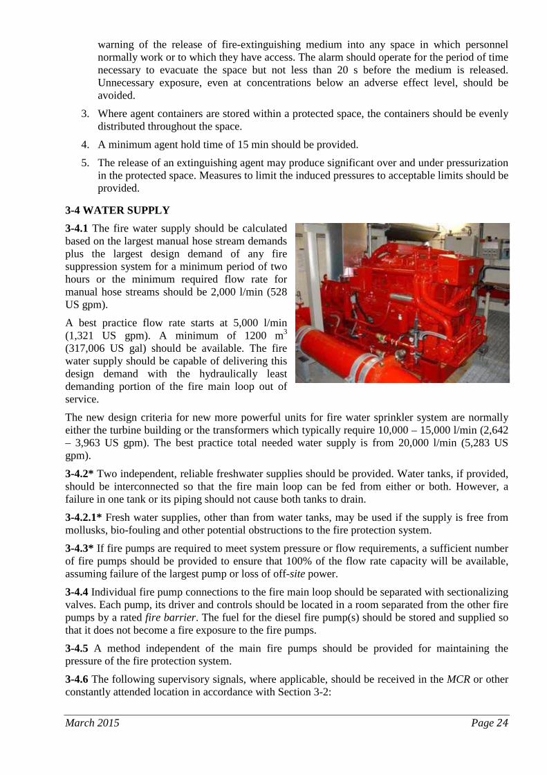
3-4 WATER SUPPLY 3-4.1 The fire water supply should be calculated based on the largest manual hose stream demands plus the largest design demand of any fire suppression system for a minimum period of two hours or the minimum required flow rate for manual hose streams should be 2,000 l/min (528 US gpm).
A best practice flow rate starts at 5,000 l/min (1,321 US gpm). A minimum of 1200 m3
(317,006 US gal) should be available. The fire water supply should be capable of delivering this design demand with the hydraulically least demanding portion of the fire main loop out of service.
The new design criteria for new more powerful units for fire water sprinkler system are normally either the turbine building or the transformers which typically require 10,000 – 15,000 l/min (2,642 – 3,963 US gpm). The best practice total needed water supply is from 20,000 l/min (5,283 US gpm).
3-4.2* Two independent, reliable freshwater supplies should be provided. Water tanks, if provided, should be interconnected so that the fire main loop can be fed from either or both. However, a failure in one tank or its piping should not cause both tanks to drain.
3-4.2.1* Fresh water supplies, other than from water tanks, may be used if the supply is free from mollusks, bio-fouling and other potential obstructions to the fire protection system.
3-4.3* If fire pumps are required to meet system pressure or flow requirements, a sufficient number of fire pumps should be provided to ensure that 100% of the flow rate capacity will be available, assuming failure of the largest pump or loss of off-site power.
3-4.4 Individual fire pump connections to the fire main loop should be separated with sectionalizing valves. Each pump, its driver and controls should be located in a room separated from the other fire pumps by a rated fire barrier. The fuel for the diesel fire pump(s) should be stored and supplied so that it does not become a fire exposure to the fire pumps.
3-4.5 A method independent of the main fire pumps should be provided for maintaining the pressure of the fire protection system.
3-4.6 The following supervisory signals, where applicable, should be received in the MCR or other constantly attended location in accordance with Section 3-2:
March 2015 Page 24

1. pump running,
2. power failure,
3. failure of engine to start automatically,
4. motor phase reversal,
5. motor loss of phase,
6. low tank water level,
7. pump control panel in “off” position,
8. low temperature in the pump room or water tank and
9. low engine fuel tank level. 3-4.7* Fire pumps should start automatically and meet the operational requirements for fire protection use. Main fire pumps should be capable of being started from both the MCR and local panel, but stopped only at the local panel to avoid inadvertent stop of pumps during fires.
3-4.8 Fixed equipment that allows testing at full rated capacity should be installed. The pumps should be tested annually at full flow. All additional testing requirements should be completed in accordance with national and / or manufacturer’s recommendations.
3.4-9* The fire main loop should be periodically flow tested.
3-5 VALVE SUPERVISION 3-5.1 There should be a periodic inspection program for all fire protection water supply and system control valves.
3-5.2 Such valves should be supervised by one of the following methods:
1. Electrical supervision with audible and visual signals in the MCR or another constantly attended location.
2. Locking valves open. Keys should be made available only to authorized personnel.
3. Sealing of valves. This option should be followed only when valves are within fenced enclosures under the control of the property owner.
3-6 FIRE MAINS, HYDRANTS AND BUILDING STANDPIPES 3-6.1* Underground fire main loops should be designed to meet all anticipated water requirements. When freezing risk exists the fire pipes special protection may be needed to prevent pipes and valves freezing. The type of pipe and water quality should be a design consideration. Corrosion, incrustation and sedimentation should be considered. Means for inspecting and flushing the systems should be provided.
3-6.2 Approved visually indicating sectional control valves should be provided to isolate portions of the fire main loop for maintenance or repair without having to shut off large portions of the water supply to fire suppression systems. Means should be provided for removing snow accumulation as appropriate so that outside fire protection valves, including fire hydrants are not obstructed.
3-6.3 Valves should be installed to permit isolation of outside hydrants from the fire main loop for maintenance or repair without interrupting the water supply to automatic or manual fire suppression systems.
3-6.4 A common fire main loop may serve multi-unit nuclear power plant sites if cross-connected between units. Sectional control valves should permit maintaining independence of the individual loop around each unit. For such installations, common water supplies may also be utilized. For multiple-reactor sites with widely separated plants (approaching 2 km (1.2 mile) or more), separate fire main loops should be used. March 2015 Page 25

3-6.5 Outside manual hose installation should be capable of providing an effective hose stream to any on-site location. Hydrants with individual hose gate valves should be installed approximately every 75 m (246 ft) on the fire main loop. Hydrants should be located in positions that are near to building entry points (including entry points to firefighting shafts containing fire mains) and appliance parking positions. At each hydrant a hose cabinet equipped with hose and combination nozzle and other auxiliary equipment should be provided. Mobile means of providing hose and associated equipment, such as hose carts or trucks, may be used in lieu of hose cabinets. Such mobile equipment should be equivalent to the equipment supplied by three hose cabinets.
3-6.6 Couplings compatible with those used by local off-site fire brigades should be provided on all hydrants, hose couplings and standpipe risers.
3-6.7 Sprinkler systems and manual hose station standpipes should have connections to the plant water main or, alternatively, headers fed from each end so that a single active failure cannot impair both the primary and back-up fire suppression systems. Each sprinkler and standpipe system should be equipped with either an OS&Y (outside screw and yoke) gate valve or other shutoff valve and water flow alarm.
3-6.8 A hose connection and standpipe system should be provided for all major buildings.
3-6.9 In the event of a design basis earthquake, the design of the fire water supply system should ensure that water will be provided to standpipes and hose connections needed for potential manual firefighting in areas containing equipment required for plant shutdown. The piping system serving such hose stations should be analyzed for earthquake loading and should be provided with supports to ensure system integrity.
3-6.10 The proper type of hose nozzle to be supplied to each area should be based on the recommendation of the FHA. The usual combination spray/straight-stream nozzle should not be used in areas where the straight stream can cause unacceptable mechanical damage. Fixed fog nozzles should be provided at locations where high-voltage shock hazards exist. All hose nozzles should have shutoff capability.
3-6.11 Separate fire water supply systems should be provided for operational and construction units.
3-7 FIRE EXTINGUISHERS 3-7.1 Fire extinguishers should be distributed, installed, inspected, maintained and tested in accordance with recognised standards. Fire extinguishers should be identified and marked.
3-7.2 Conspicuous markings should clearly identify the location of each portable and wheeled fire extinguisher.
3-7.3 For areas containing large fire loads, e.g. the turbine hall, use of more effective portable extinguishers are advised. Such equipment can be 50 kg (110 lb) or larger wheeled dry powder units, mobile foam equipment and water monitors.
March 2015 Page 26

Chapter 4 – Station Fire Brigade
4-1 ORGANISATION 1. There should be an on-site station fire brigade with a minimum strength of five members
(qualified firefighters) available at all times.
2. The fire brigade leader and at least two other brigade members should have sufficient knowledge of the station’s safety related systems to be able to anticipate the consequences of a fire on the station’s shutdown capability (see Chapter 5 on Specific Consideration for Nuclear Risks).
3. The on-site station fire brigade members should be:
1. full-time fire fighters with no other assigned duties or
2. station operational staff with other tasks, but trained and on-call for fire protection duty should an alarm occur or
3. a combination of full-time and part-time (i.e. drawn from the station staff) fire fighters.
4. The fire brigade should always be notified immediately upon a fire alarm.
4-2 TRAINING AND DRILLS 1. Fire brigade members should be
physically able to perform all anticipated duties and tasks throughout their period of service. In addition to an annual medical examination, members should be given regular checks to demonstrate that they can:
1. perform the expected strenuous activities and
2. use and operate the appropriate personal protective equipment.
2. New brigade members should be given initial intensive training and practice in firefighting consistent with recognised standards, and all fire fighters should receive periodic retraining so they remain skilled. In addition to the standard responses to hazardous material incidents, the training programs should include responses to the radioactivity and health physics hazards that may be encountered during a fire.
3. The fire brigade training program should be documented and current. Records of individual station fire brigade members should show:
1. confirmation of classroom and hands-on training details,
2. initial training received,
3. refresher training given,
4. special training,
5. drill attendance records and
6. leadership command and control training, where appropriate.
4. In addition to training, drills are essential to test, maintain and strengthen the fire brigade’s response capability. Regular drills serve to:
March 2015 Page 27

1. improve the brigade’s performance as a team,
2. ensure the proper use of equipment,
3. confirm effectiveness of pre-fire planning and
4. test the brigade’s coordination with other groups, such as station emergency response teams and external emergency organizations.
5. Drills should be periodically conducted in various plant areas for each shift team. Drill scenarios should be planned and particular emphasis should be placed on areas identified by the plant’s FHA/FSSA as being vital to plant operation and/or containing significant fire hazards.
6. Drills should be used to evaluate the skills of all brigade members against established performance standards. An adequate number of monitors should be posted during the drill to evaluate the brigade team and individual team members.
7. Complete drill records should be kept describing:
1. drill scenarios,
2. fire brigade member responses and
3. ability of the fire brigade to perform its assigned duties.
8. After each drill, a critique should be held to determine if the drill objectives were met. The lessons learned should be used to modify the fire brigade’s training program or, if necessary, the corresponding pre-fire plans.
All employees should receive basic fire safety training including how to sound the alarm if a fire is discovered and to intervene with portable extinguishers when possible.
4-3 COMMUNICATIONS 1. All emergency and hazardous situations should receive priority on the station
communication system, with a series of recognizable signals or tones to distinguish each type of emergency.
2. In the event of a fire, in addition to fire warning and evacuation announcements, the communication system should also be available to direct the fire brigade. Communication equipment has to have sources of uninterrupted or reserve power supply, for ensuring functionality in an emergency.
3. Since the operations staff may be required to place the plant in a safe shutdown condition in the event of a fire, there should be a portable radio communication system available for the fire brigade and operations personnel. Periodic testing should ensure that portable radio transmission frequencies neither affect the operation of station electrical control components nor interfere with the communication channels used by the plant’s security forces.
4. The impact of fire damage should be considered when radio repeaters are installed. They should be located such that a fire-induced failure will not result in the failure of other communication systems needed to achieve safe shutdown.
4-4 LIAISON WITH EXTERNAL EMERGENCY ORGANIZATIONS 1. The station fire brigade should be capable of protecting safety-related station areas
unassisted. For the overall fire protection program, however, response by off-site firefighting resources should be developed for supplemental and back-up purposes.
2. The off-site brigade should receive instruction and training in the hazards associated with entering and fighting fires involving radioactive and hazardous materials. They should
March 2015 Page 28

observe and advise on station fire drills and participate in the drills and the post-drill critiques.
3. Station fire protection management should regularly meet with the external emergency organizations. Plans should be developed for the interface of the station fire brigade with the external organizations. The responsibilities and duties of each should be defined and revised should post-drill critiques indicate improvements or modifications are required.
4. Station fire brigade should only respond to on-site fires. Assistance to local authorities can be given, should the resources available during the shift exceed the minimum required for the nuclear station.
5. The station management should ensure all necessary and appropriate procedures are in place to ensure command and control of the incident is maintained. The following issues should be addressed:
1. Communications structure, in particular where there is a cascade decision process involving a number of levels of management, or where it is intended to investigate first alarms before sounding warnings and calling the external organizations;
2. Inspection, testing and maintenance of the call-out system and redundant systems under emergency conditions;
3. Meeting the external fire service and providing them with information and advice;
4. Security arrangements are suitable and do not prevent/restrict evacuation to a safe area, or restrict the needs of the external fire service to enter the building to affect firefighting or assist the station fire service.
4-5 STATION FIRE BRIGADE EQUIPMENT 1. The station fire brigade should be provided with equipment that will enable them to perform
their assigned tasks. The minimum equipment provided for the brigade should consist of personal protective equipment such as turnout coats, boots, gloves, hard hats, emergency communications equipment, portable lights and portable ventilation equipment. All equipment should be approved for firefighting use.
2. Self-contained breathing apparatus using full-face positive pressure masks should be provided. Back-up supply of bottles and replenishment of these should be available on-site.
3. One or more on-site mobile fire apparatus may be required if an off-site mobile fire apparatus is not readily available. Depending on the station’s needs, the vehicle should be equipped with a fire pump, water tank, hose and other equipment. A sufficient number of the members of the fire brigade should be able to drive and operate the existing vehicles and the shifts arranged accordingly.
Chapter 5 – Specific Consideration for Nuclear Risks
5-1 SPECIFIC CONSIDERATION FOR NUCLEAR RISKS
1. The goals of nuclear safety-related fire protection are listed in 1-1.2.
2. To meet these goals, various structures, systems and components important to nuclear safety should be appropriately designed and constructed. They should be protected by fire protection systems where there is a need to mitigate fire risk.
March 2015 Page 29

5-2 NUCLEAR REACTOR SAFETY CONSIDERATIONS
5-2.1 Fire Analyses 1. To ensure that fire protection goals are met, the FHA should be current.
2. The portion of the FHA related to nuclear safety should incorporate the FSSA of the effects of a fire on all structures, systems and components required to achieve safe shutdown.
3. The FSSA should include a comprehensive list of essential equipment whose fire-induced failure or mis-operation could prevent safe shutdown of the reactor. Fire induced failure includes damage to electrical circuits and associated circuits such as open circuits, hot shorts and shorts to ground in any single fire cell or fire compartment that contains any portion of the required safe shutdown circuit.
4. The FSSA should analyze all expected modes of operation.
5. During shutdown periods, many fire protection systems may not be operable (e.g., fire barriers incomplete, extinguishing systems shut off). Safe shutdown related equipment may have been made inoperable due to maintenance and abnormal reactor conditions (e.g., open reactor, lower water level). These differing conditions should be considered when performing the shutdown period analysis.
6. A separate analysis of seismic/fire interaction should be performed to consider the possibility of seismically-initiated fires, induced spurious suppression system actuation, degradation of suppression capability, or initiation of a fire in a non-safety system that may affect a safety system. Appropriate modifications (e.g., procedures or equipment) should be developed.
7. An analysis of the consequences of an interaction of fire and internal flooding caused by the fire (from fire water and/or damaged water pipes) should also be performed.
8. With the exception of the inerted primary containment area, it should be assumed that a fire can disable or spuriously activate systems or equipment.
9. If safe shutdown requirements are not fulfilled in a specific area, a more detailed analysis of this area should be performed. The analysis may support the conclusion that more fire protection systems need to be installed or alternatively that due to spatial separation, installed fire resistive barriers, etc. that no further measures are needed.
10. The FHA and FSSA should be refined and developed into a station-specific Fire Probabilistic Safety Analysis.
11. The effects of terrorist action on plant fire protection should be considered.
5-2.2 Safe Shutdown Systems and Equipment 1. Where full separation of shutdown functions by fire compartments is not possible,
unimpaired ability to achieve safe shutdown should be demonstrated by using recognised fire modeling techniques as evaluated in the FHA.
2. All nuclear safety related areas should be equipped with fire detection systems with alarm panels in the MCR (see Section 3-2).
3. There is an unavoidable lack of separation of instrumentation and control in the MCR. To ensure safe shutdown and residual heat removal capability in the case of a fire in the MCR itself, there should be an Emergency Control Area (ECA), fully separated from the MCR, preferably in a separate building with a protected route, from which shutdown operations can be controlled.
March 2015 Page 30
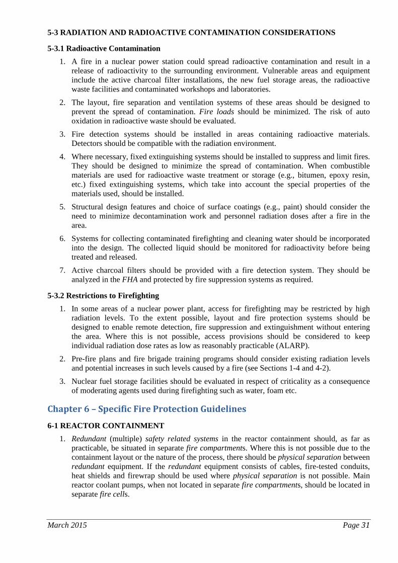
5-3 RADIATION AND RADIOACTIVE CONTAMINATION CONSIDERATIONS
5-3.1 Radioactive Contamination 1. A fire in a nuclear power station could spread radioactive contamination and result in a
release of radioactivity to the surrounding environment. Vulnerable areas and equipment include the active charcoal filter installations, the new fuel storage areas, the radioactive waste facilities and contaminated workshops and laboratories.
2. The layout, fire separation and ventilation systems of these areas should be designed to prevent the spread of contamination. Fire loads should be minimized. The risk of auto oxidation in radioactive waste should be evaluated.
3. Fire detection systems should be installed in areas containing radioactive materials. Detectors should be compatible with the radiation environment.
4. Where necessary, fixed extinguishing systems should be installed to suppress and limit fires. They should be designed to minimize the spread of contamination. When combustible materials are used for radioactive waste treatment or storage (e.g., bitumen, epoxy resin, etc.) fixed extinguishing systems, which take into account the special properties of the materials used, should be installed.
5. Structural design features and choice of surface coatings (e.g., paint) should consider the need to minimize decontamination work and personnel radiation doses after a fire in the area.
6. Systems for collecting contaminated firefighting and cleaning water should be incorporated into the design. The collected liquid should be monitored for radioactivity before being treated and released.
7. Active charcoal filters should be provided with a fire detection system. They should be analyzed in the FHA and protected by fire suppression systems as required.
5-3.2 Restrictions to Firefighting 1. In some areas of a nuclear power plant, access for firefighting may be restricted by high
radiation levels. To the extent possible, layout and fire protection systems should be designed to enable remote detection, fire suppression and extinguishment without entering the area. Where this is not possible, access provisions should be considered to keep individual radiation dose rates as low as reasonably practicable (ALARP).
2. Pre-fire plans and fire brigade training programs should consider existing radiation levels and potential increases in such levels caused by a fire (see Sections 1-4 and 4-2).
3. Nuclear fuel storage facilities should be evaluated in respect of criticality as a consequence of moderating agents used during firefighting such as water, foam etc.
Chapter 6 – Specific Fire Protection Guidelines
6-1 REACTOR CONTAINMENT 1. Redundant (multiple) safety related systems in the reactor containment should, as far as
practicable, be situated in separate fire compartments. Where this is not possible due to the containment layout or the nature of the process, there should be physical separation between redundant equipment. If the redundant equipment consists of cables, fire-tested conduits, heat shields and firewrap should be used where physical separation is not possible. Main reactor coolant pumps, when not located in separate fire compartments, should be located in separate fire cells.
March 2015 Page 31
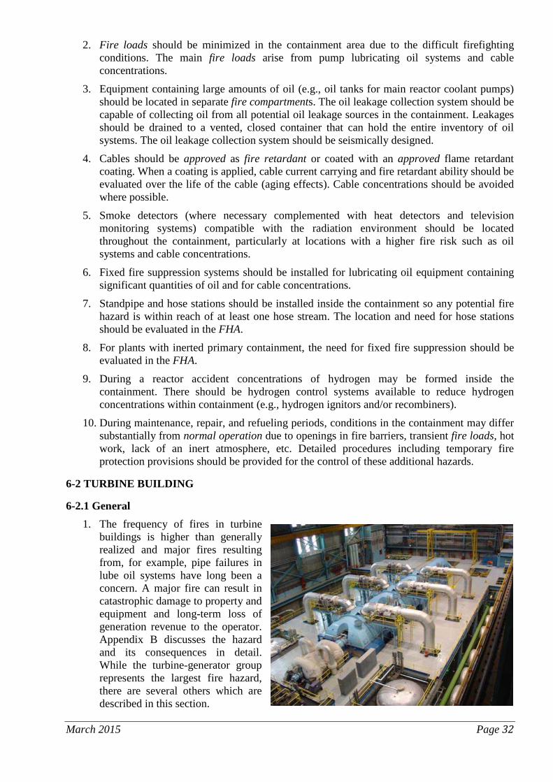
2. Fire loads should be minimized in the containment area due to the difficult firefighting conditions. The main fire loads arise from pump lubricating oil systems and cable concentrations.
3. Equipment containing large amounts of oil (e.g., oil tanks for main reactor coolant pumps) should be located in separate fire compartments. The oil leakage collection system should be capable of collecting oil from all potential oil leakage sources in the containment. Leakages should be drained to a vented, closed container that can hold the entire inventory of oil systems. The oil leakage collection system should be seismically designed.
4. Cables should be approved as fire retardant or coated with an approved flame retardant coating. When a coating is applied, cable current carrying and fire retardant ability should be evaluated over the life of the cable (aging effects). Cable concentrations should be avoided where possible.
5. Smoke detectors (where necessary complemented with heat detectors and television monitoring systems) compatible with the radiation environment should be located throughout the containment, particularly at locations with a higher fire risk such as oil systems and cable concentrations.
6. Fixed fire suppression systems should be installed for lubricating oil equipment containing significant quantities of oil and for cable concentrations.
7. Standpipe and hose stations should be installed inside the containment so any potential fire hazard is within reach of at least one hose stream. The location and need for hose stations should be evaluated in the FHA.
8. For plants with inerted primary containment, the need for fixed fire suppression should be evaluated in the FHA.
9. During a reactor accident concentrations of hydrogen may be formed inside the containment. There should be hydrogen control systems available to reduce hydrogen concentrations within containment (e.g., hydrogen ignitors and/or recombiners).
10. During maintenance, repair, and refueling periods, conditions in the containment may differ substantially from normal operation due to openings in fire barriers, transient fire loads, hot work, lack of an inert atmosphere, etc. Detailed procedures including temporary fire protection provisions should be provided for the control of these additional hazards.
6-2 TURBINE BUILDING
6-2.1 General 1. The frequency of fires in turbine
buildings is higher than generally realized and major fires resulting from, for example, pipe failures in lube oil systems have long been a concern. A major fire can result in catastrophic damage to property and equipment and long-term loss of generation revenue to the operator. Appendix B discusses the hazard and its consequences in detail. While the turbine-generator group represents the largest fire hazard, there are several others which are described in this section.
March 2015 Page 32

2. Fire protection recommended in this Guideline for turbine-generator oil systems is based on the use of mineral oil. When a less flammable or fire resistant type of lubrication is used, the recommended level of fire suppression may be decreased. A decrease in the level of fire protection is only acceptable when the FHA can clearly demonstrate the relative safety of the fire-resistant fluid. The specific lubricant used should be tested and approved under conditions that would simulate actual use including ignition of oil soaked insulation, ignition of an atomized oil spray and ignition of an oil pool. A decrease in the recommended protection would only be acceptable in those areas where the ignition would not be expected to sustain a fire or cause significant damage.
3. A detailed, fire focused review of oil systems, potential for release and realistic fire scenarios should be undertaken as part of the FHA. The control measures in place should be confirmed as suitable to ensure effective management of an oil fire, e.g. operator training, maintenance, suitable draining and curbage, fire protection systems available.
6-2.2* Oil Piping 1. The oil piping system should be designed to reduce the consequences of an oil leak. Three
common methods are used:
1. welded pipe, so that screwed joints can be avoided wherever possible,
2. concentric pipe whereby the pressurized oil pipe lies inside the oil drain pipe and
3. a drainage channel leading back to the oil room or another safe location.
2. The quantity of oil released during a turbine-generator fire may be reduced if consideration is given during the fire emergency to:
1. stop rotation of the turbine-generator as soon as possible and
2. secure all lube oil pumps.
3. Spray shields should be fitted around flanged joints, flanged bonnets and any other flanged or threaded connections of oil fuel and lubricating oil systems having an internal pressure exceeding 0.18 N/mm2 (26.5 psi) which have the possibility of being in contact with potential ignition sources by direct spray or by reflection. The purpose of spray shields is to prevent the impingement of sprayed oils onto a high temperature surface or other source of ignition.
6-2.3 Nonporous Insulation Nonporous insulation should be used on all hot surfaces that can be exposed to oil leakage in the turbine building since absorbed oil can become an ignition source.
6-2.4* Turbine and Generator Bearings and Oil Piping All turbine and generator bearings and associated oil piping above the operating floor should be protected by one of the following properly engineered systems listed in order of preference:
1. A fully automatic water-based fire suppression system designed to protect all areas around the turbine-generator group where oil can be released or can accumulate or
2. A manual water-based fire suppression system designed to protect all areas around the turbine-generator group where oil can be released or can accumulate. System actuation should be from either of two remote locations, one of which should be the MCR. Operating and training procedures should be prepared to minimize delays between detection of the fire and operation of the suppression system.
March 2015 Page 33

6-2.5 Shaft Driven Generator Exciter The bearings and associated oil piping above the operating floor of the shaft driven generator exciter should be protected by one of the following properly engineered systems:
1. A water-based fire suppression system. An automatic system is preferred. A manual system is acceptable provided it can be actuated from a safe place.
2. If the exciter is totally enclosed, an automatic carbon dioxide suppression system designed to maintain a 30% concentration inside the enclosure during the coast down period of the machine.
3. If the exciter is totally enclosed, a manual carbon dioxide suppression system of sufficient capacity for multiple discharge cycles, capable of being actuated from a safe place.
6-2.6* Below the Turbine-Generator Group 1. A properly engineered fire sprinkler or foam water sprinkler system should be provided
below the operating floor in all areas where combustible oil could spread or accumulate.
2. For the main condenser pit fixed-foam protection is an acceptable alternative to fire sprinklers or foam water sprinklers.
6-2.7* Oil Storage Tanks, Reservoirs and Purifiers 1. Turbine lube oil storage tanks and reservoirs should be physically separated from all other
areas (see Section 2-4.3).
2. A properly engineered fire suppression system should be provided to protect all such equipment.
3. An oil containment system should be provided, (see Section 6-2.8 for details).
4. Where oil storage tanks are not separated from other areas, they are acceptable provided that:
1. they are located in areas protected by an overhead fire sprinkler system or
2. the tanks are protected by an automatic water spray system and
3. an oil containment system is installed in accordance with Section 6-2.8.
5. To prevent potential damage from the effects of water spray, emergency lube oil pumps should be of the enclosed type with the electrical circuits to the oil pump motors routed and protected so that control will not be impaired by the fire emergency.
6. Turbine oil reservoirs and lube oil filters equipped with hinged access panels designed to relieve internal pressure should have tamper resistant devices installed so that pressure relief of the tank is not defeated, e.g. locked cages can be installed over the covers arranged so that the covers can be lifted.
7. Non-condensable vapour extractors should be vented to the outdoors.
March 2015 Page 34

8. Lube oil purifiers should be located in an area protected by an automatic water-based suppression system and an oil containment system.
6-2.8* Oil Containment 1. Liquid containment systems should be provided to limit an oil spill to an acceptable area.
The size of the area should be determined in the FHA based on the anticipated volume of oil released and the volume of water expected to be used for firefighting.
2. Pre-fire plans should address the problems created by hazardous and/or contaminated wastes.
6-2.9* Auxiliary Turbines, Large Pumps and Motors 1. Auxiliary turbines, feed pumps and motor
generator sets having oil system capacities greater than 200 liters (52.8 US gal) should be physically separated and protected by:
1. a properly engineered automatic fire sprinkler system, and
2. an oil containment system in accordance with Section 6-2.8.
6-2.10* Hydrogen Systems 1. Hydrogen storage and use should include
the following features:
1. Bulk storage should be located outdoors detached from the plant and other buildings by a distance determined by the FHA.
2. Excess flow valves should be installed in the supply piping.
3. A clearly marked outdoor block valve should be provided.
4. Make-up should be done manually as required.
5. Hydrogen usage should be logged.
6. A remotely operated dump valve should be installed and located in a safe area in the case of a fire in the turbine hall. Clear instructions on the operation of the valve should be provided in the area of the valve. The hydrogen should be vented to an area clear of ignition sources.
2. Prior to maintenance on the electrical generator or in the case of an emergency, hydrogen should be released and the generator flushed with an inert gas in accordance with manufacturer’s recommendations. Valves to be operated for hydrogen release and flushing should be easily accessible during emergency situations and clearly marked. Remote control of these valves should be considered.
3. Subsequent to flushing, when the generator is opened for maintenance a blank flange should be inserted into the hydrogen supply piping or a spool piece removed from the piping.
6-2.11* Hydrogen Seal Oil Systems 1. Hydrogen seal oil systems should be physically separated and protected by a properly
engineered fire sprinkler system.
2. Where separation is not provided, the hydrogen seal oil system should be:
March 2015 Page 35

1. located in an area protected by a properly engineered sprinkler system or water spray system and
2. provided with an oil containment system in accordance with Section 6-2.8.
6-2.12 Hydraulic Control Systems 1. Approved fire-resistant hydraulic fluids should be used in hydraulic systems. When
ordinary mineral oil hydraulic fluids are used, they should be protected by a fire suppression system.
2. Curbing and drainage should be provided for the hydraulic oil reservoir.
6-2.13* Smoke and Heat Venting If sprinklers are not installed at the ceiling, permanent smoke and heat venting should be provided in the turbine building.
6-3 ELECTRICAL EQUIPMENT
6-3.1 General Electrical equipment can create a fire hazard by nature of its location, cooling system or insulating material. Electrical installations and equipment should comply with recognised standards.
1. The fire hazard should be minimized by using fire retardant cable insulation wherever practicable.
2. If equipment contains liquids for insulating and/or cooling purposes, such liquids should have a high flash point and the volume should be minimized. This equipment should be installed with adequate fire protection.
3. For locations where fire or explosion hazards may exist due to flammable gases, flammable liquids, combustible dust or fibers, electrical equipment should be approved for use in this type of atmosphere.
6-3.2 Specific Equipment
6-3.2.1* Fluid Filled Transformers Transformer mineral oil will vaporize at high temperatures as a result of overloading or electrical arcing. The high temperature can result in an overpressure condition and failure of the transformer tank enclosure. A rapid release of mineral oil heated above its ignition temperature can result in a fire with intensity proportional to the volume of oil released. Fire protection measures should be provided as listed below. Exceptions to the recommended fire protection are acceptable when the FHA can demonstrate the level of existing protection will satisfy the goals listed in Section 1-1.2.
1. Outdoor oil-filled transformers should be protected by an automatic water spray system where a fire could cause damage to adjacent equipment or buildings. The water spray system should be designed to provide protection for the entire transformer, the nonabsorbing oil spill area and the exposed iso-phase bus. Buildings and equipment within 15 meters in any direction of the transformer should be protected by fire barriers.
March 2015 Page 36
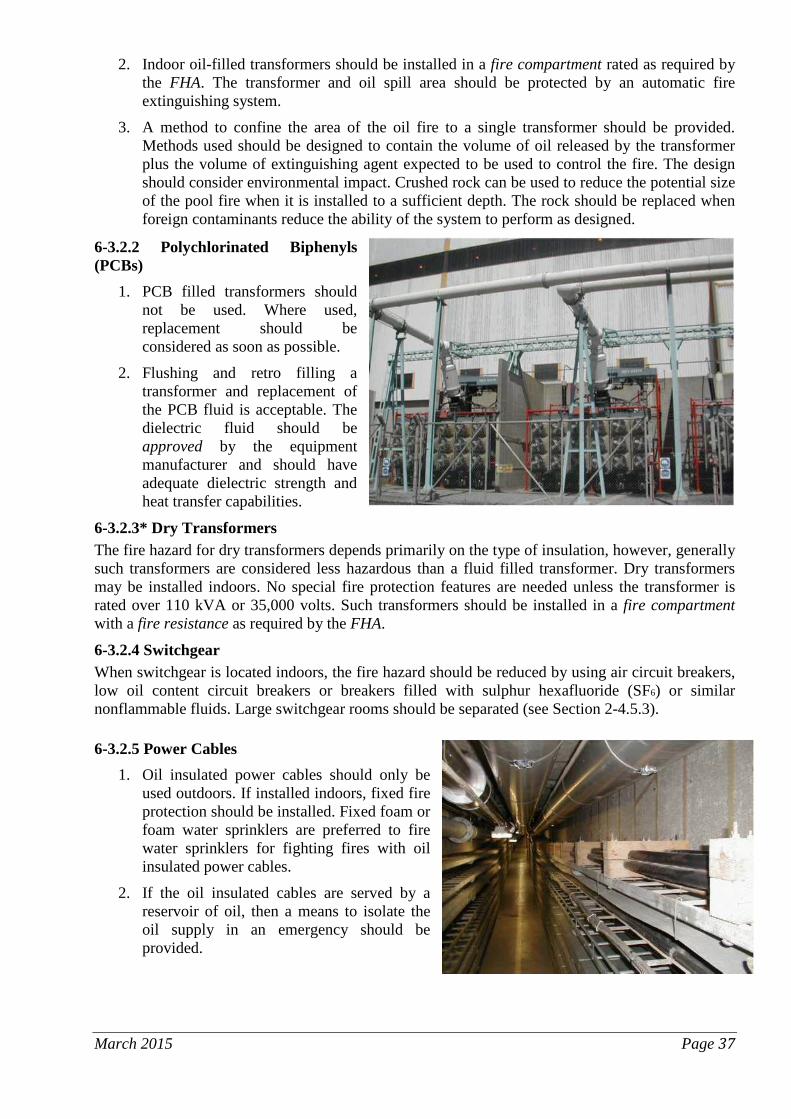
2. Indoor oil-filled transformers should be installed in a fire compartment rated as required by the FHA. The transformer and oil spill area should be protected by an automatic fire extinguishing system.
3. A method to confine the area of the oil fire to a single transformer should be provided. Methods used should be designed to contain the volume of oil released by the transformer plus the volume of extinguishing agent expected to be used to control the fire. The design should consider environmental impact. Crushed rock can be used to reduce the potential size of the pool fire when it is installed to a sufficient depth. The rock should be replaced when foreign contaminants reduce the ability of the system to perform as designed.
6-3.2.2 Polychlorinated Biphenyls (PCBs)
1. PCB filled transformers should not be used. Where used, replacement should be considered as soon as possible.
2. Flushing and retro filling a transformer and replacement of the PCB fluid is acceptable. The dielectric fluid should be approved by the equipment manufacturer and should have adequate dielectric strength and heat transfer capabilities.
6-3.2.3* Dry Transformers The fire hazard for dry transformers depends primarily on the type of insulation, however, generally such transformers are considered less hazardous than a fluid filled transformer. Dry transformers may be installed indoors. No special fire protection features are needed unless the transformer is rated over 110 kVA or 35,000 volts. Such transformers should be installed in a fire compartment with a fire resistance as required by the FHA.
6-3.2.4 Switchgear When switchgear is located indoors, the fire hazard should be reduced by using air circuit breakers, low oil content circuit breakers or breakers filled with sulphur hexafluoride (SF6) or similar nonflammable fluids. Large switchgear rooms should be separated (see Section 2-4.5.3).
6-3.2.5 Power Cables 1. Oil insulated power cables should only be
used outdoors. If installed indoors, fixed fire protection should be installed. Fixed foam or foam water sprinklers are preferred to fire water sprinklers for fighting fires with oil insulated power cables.
2. If the oil insulated cables are served by a reservoir of oil, then a means to isolate the oil supply in an emergency should be provided.
March 2015 Page 37

6-3.2.6* Controls and Relays 1. The doors for cabinets containing controls and relays should remain closed during plant
operation. Large relay rooms and rooms containing safety related equipment should be separated by rated fire barriers.
2. Control and relay cabinets should be tested periodically for proper operation of their cooling systems.
6-3.2.7* Battery rooms 1. Battery rooms and associated inverters should be physically separated from other rooms
(see Section 2-4.5.6). 2. Battery rooms should be equipped with adequate forced ventilation. Exhaust should be
located at the highest level of the compartment. Hydrogen concentrations in battery rooms should be monitored. Excessive concentrations (>0.5-1 volume %) or loss of ventilation should sound an alarm signal at a constantly attended location.
3. Electrical equipment installed or used in battery rooms should in accordance a recognized national or international standard.
6-3.2.8 Computer and Communication Rooms 1. High value or important computers and communications equipment should be physically
separated from other areas (see Section 2-4.5.2). These compartments should be protected against water leakage from the floors above. Fire loads should be minimized by:
1. limiting the contents to the computer, its support equipment and non-combustible office furniture needed for operation and
2. using only self-extinguishing-type trash receptacles.
2. Standard office functions should not be permitted inside the computer room.
3. Additional reserves of paper, inks, recording media and other combustible material should be stored in a separate area outside the room.
4. Records should be stored outside the computer room in a room designated specifically for such storage.
5. Smoke detectors should be located at the ceiling level of the rooms, underneath the raised floor (if applicable) and in the cabinets, particularly if they are directly vented. Access to the space under raised floors should not be restricted and tools necessary for access clearly marked and readily available in the computer room.
6. With regard to fire suppression the following should be observed:
1. Properly engineered fixed extinguishing systems should be provided.
2. Multipurpose dry chemicals should not be used.
3. If sprinkler systems are used in computer areas, they should be of the pre-action type and have their own sprinkler control valve.
4. Computers critical to operation should have provisions for backup in another fire compartment.
March 2015 Page 38

6-3.3 Lightning Protection 6-3.3.1 Design Principles
1. All structures, including buildings, above ground tanks, stacks, meteorological towers, etc., should be protected by an effective lightning protection system. The “exterior” and “interior” parts of the lightning protection system(s) should be designed to account for any special circumstance and layout of the facility.
2. The “exterior” part of the lightning protection system should intercept the lightning strike by air terminals and lead the current to earth (ground terminals) without causing damage to any station buildings. A lightning strike counter should be provided. The counter should be inspected periodically and after a lightning impact has been registered in the counter.
3. A suitable combination of potential equalization, shielding and surge suppression should be used in the “interior” part of the lightning protection system to prevent damage to the metallic and electric installations due to induced currents and electromagnetic fields from lightning discharges.
6-3.3.2 Maintenance for Lightning Protection All lightning protection systems should be periodically inspected and maintained. Periodic inspection and maintenance is of particular importance where electrolytic corrosion can occur from the use of copper and aluminum conductor materials. Modifications to the system should be tested to assure continued proper operation.
6-3.4* Maintenance for Electrical Equipment Proper maintenance of electrical equipment and systems is important to minimize the potential for a fire.
1. Important electrical equipment should be checked on a regular basis for “hotspots” (e.g., using thermographic methods), insulation damage and other faults likely to become ignition sources.
2. Electrical power cable connections should be regularly checked for loose connections which may also lead to hotspots.
3. All electrical and electronic equipment should be cleaned periodically to remove dust.
4. Electrical equipment containing oil should be periodically checked for the presence of leakage.
6-3.5 Firefighting Involving Electrical Equipment When fighting fires involving electrical equipment, the following precautions should be observed.
1. Electrical equipment need not be de-energized prior to discharge of gas or dry chemical fire suppression systems. However, shutdown is desirable if it can be accomplished.
2. Portable fire extinguishers that contain water, water/antifreeze or foam should generally not be used on energized electrical equipment because of the potential for electrical shock to personnel.
3. The use of multipurpose dry chemical systems for fire suppression is not recommended in locations having sensitive electronic equipment.
4. The use of hand hose lines discharging water onto energized electrical equipment should take personal safety into consideration.
6-4* CONTROL BUILDINGS 1. The MCR should be protected from fire and smoke (see Section 2-4.5.1).
March 2015 Page 39
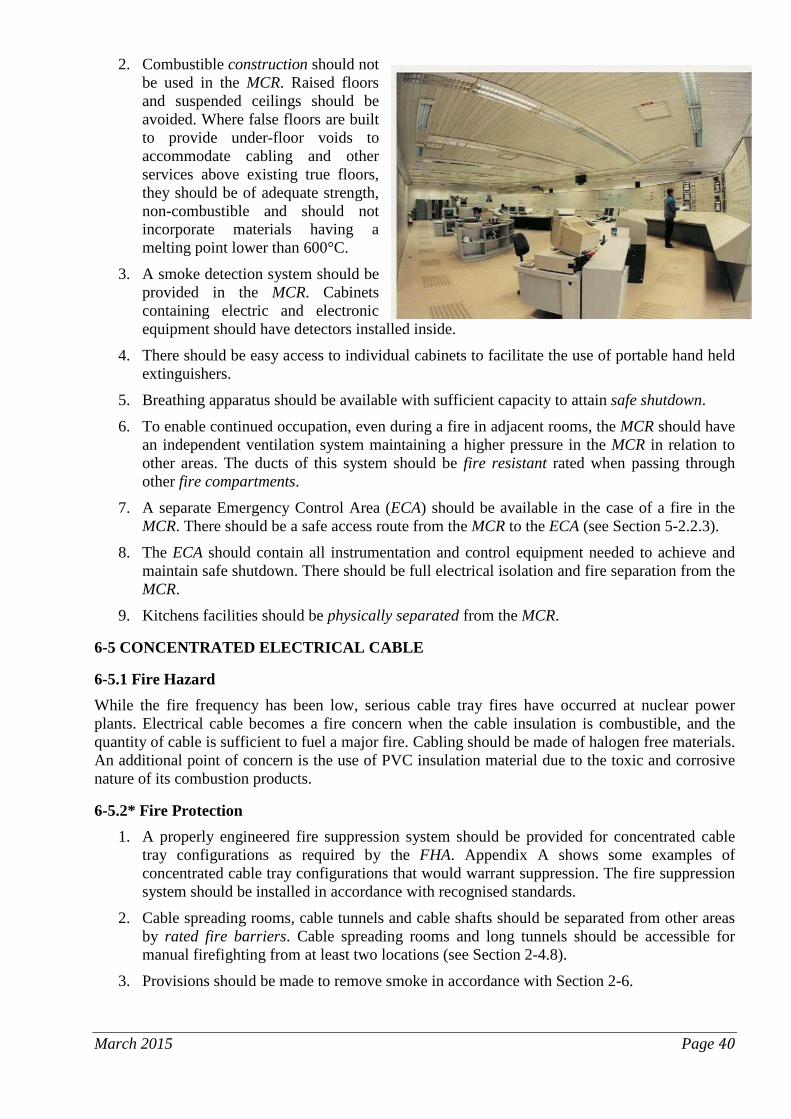
2. Combustible construction should not be used in the MCR. Raised floors and suspended ceilings should be avoided. Where false floors are built to provide under-floor voids to accommodate cabling and other services above existing true floors, they should be of adequate strength, non-combustible and should not incorporate materials having a melting point lower than 600°C.
3. A smoke detection system should be provided in the MCR. Cabinets containing electric and electronic equipment should have detectors installed inside.
4. There should be easy access to individual cabinets to facilitate the use of portable hand held extinguishers.
5. Breathing apparatus should be available with sufficient capacity to attain safe shutdown.
6. To enable continued occupation, even during a fire in adjacent rooms, the MCR should have an independent ventilation system maintaining a higher pressure in the MCR in relation to other areas. The ducts of this system should be fire resistant rated when passing through other fire compartments.
7. A separate Emergency Control Area (ECA) should be available in the case of a fire in the MCR. There should be a safe access route from the MCR to the ECA (see Section 5-2.2.3).
8. The ECA should contain all instrumentation and control equipment needed to achieve and maintain safe shutdown. There should be full electrical isolation and fire separation from the MCR.
9. Kitchens facilities should be physically separated from the MCR.
6-5 CONCENTRATED ELECTRICAL CABLE
6-5.1 Fire Hazard While the fire frequency has been low, serious cable tray fires have occurred at nuclear power plants. Electrical cable becomes a fire concern when the cable insulation is combustible, and the quantity of cable is sufficient to fuel a major fire. Cabling should be made of halogen free materials. An additional point of concern is the use of PVC insulation material due to the toxic and corrosive nature of its combustion products.
6-5.2* Fire Protection 1. A properly engineered fire suppression system should be provided for concentrated cable
tray configurations as required by the FHA. Appendix A shows some examples of concentrated cable tray configurations that would warrant suppression. The fire suppression system should be installed in accordance with recognised standards.
2. Cable spreading rooms, cable tunnels and cable shafts should be separated from other areas by rated fire barriers. Cable spreading rooms and long tunnels should be accessible for manual firefighting from at least two locations (see Section 2-4.8).
3. Provisions should be made to remove smoke in accordance with Section 2-6.
March 2015 Page 40

4. One standpipe connection should be available at each entrance to cable spreading rooms, cable tunnels and cable shafts.
5. Drainage of sprinkler and hose stream water should be provided in accordance with Section 2-8.
6-6 MISCELLANEOUS AREAS
6-6.1 Engine Driven Emergency Power Supplies 6-6.1.1 Fire Hazard
1. The principal fire hazard associated with combustion turbine and diesel driven electric generators is the fuel oil and lubricating oil systems. Both of these oils represent a combustible liquid hazard.
2. Fires can occur at any point where combustible oil can be released or where it can accumulate. These areas include the engine compartment, generator compartment, auxiliary equipment enclosures that contain oil, and combustion turbine exhaust compartments. Where the oil is being released, it will burn with the intensity of a pressurized oil fire. Where the oil accumulates it will burn with the characteristics of a combustible liquid pool fire. Where insulation is present, there is the possibility that it could become oil soaked and burn with the characteristics of a deep-seated fire (see Section 6-2.3).
6-6.1.2* Fire Protection 1. A properly engineered fully automatic fire suppression system should be provided in all
areas where combustible liquids may be released.
2. Curbing and drainage should be used to reduce the area exposed to an oil spill fire (see Section 2-8).
3. Each emergency electrical generating system should be in a separate fire compartment (see Section 2-4.3.5).
4. Fire suppression systems should be designed and maintained so they do not impair the reliability of the emergency power supply.
5. Fuel storage tanks containing large volumes should be located outdoors so that a fire occurring at the storage tank will not cause damage to buildings or other equipment. Outdoor aboveground tanks should be installed in accordance with good engineering practices. They should be separated from other buildings and equipment by rated fire barriers or by 15 m (49.2 ft) separation.
6. Fuel oil tanks located inside buildings should be in separate fire compartments.
7. Fuel isolating valves should be located and operable from a position not rendered inaccessible by a fire, where practicable this should be a minimum of 5 m (16.4 ft) away from the engine. The fuel isolating valves should be protected from inadvertent operation.
8. The insulation of the exhaust gas manifold may be considered sturdy and satisfactory; however, special attention should be given to insulating the manifold supports since they are susceptible to becoming hot surfaces due to heat transfer.
March 2015 Page 41

9. All external high pressure fuel delivery lines between the high pressure fuel pumps and fuel injectors are required to be protected with a jacketed piping system capable of containing fuel from a high pressure line failure.
6-6.2 Warehousing 6-6.2.1 Fire Hazard A warehouse at a nuclear power plant can contain a mix of commodities ranging from low hazard items such as metal replacement parts, to high hazard items such as plastics or flammable liquids. Each warehouse should be evaluated based upon its contents and construction. A warehouse fire can have a significant economic impact because many of the replacement parts are unique and have stringent quality control requirements.
6-6.2.2* Storage Arrangement 1. Within the warehouse, aisles between storage piles should be kept clear to provide access
for firefighting and reduce the possibility of the spread of fire. Aisle width should be increased as the height of the storage increases.
2. Flammable and combustible liquids should not be stored in the general warehouse area. They should be stored at other locations preferably in separate rooms designed for hazardous storage. Such rooms should be separated by rated fire barriers.
3. Aerosol products should not be stored in the general warehouse area unless they are contained in a separate room or caged.
4. Idle combustible pallets should not be stored inside the building. They should be stored outdoors separated from other structures by more than 15 m (49.2 ft).
5. PE (polyethylene) or PP (polypropylene) storage boxes result in increased fire load and once ignited may produce a fire that will be difficult to extinguish. Plastic boxes if used should be limited and physically separated.
6. The storage of critical spare parts should be given special attention.
7. Electrical vehicles should have charging areas in their own fire cells with individual ventilation to the outside.
8. When not in use, idle trucks should be controlled to prevent unauthorised use.
6-6.2.3* Fire Protection 1. Warehouses should be separated from other structures by a clear space of 15 m (49.2 ft) or
separated from all other areas by a rated fire barrier.
2. Warehouse buildings should be subdivided by rated fire barriers to avoid concentrations of high values.
3. As a general rule, a properly engineered fire sprinkler system should be provided in warehouses.
4. A standpipe system should be provided in the warehouse.
6-6.3 Office Buildings A fire detection system should be provided in all offices. Automatic sprinkler protection should be provided in offices and associated storage rooms that contain combustible materials which present fire or smoke exposure that could affect plant operations or critical equipment.
6-6.4 New Fuel Area 1. Fire load in the area utilized for the storage of new fuel should be minimized.
2. An automatic fire detection system should be provided in the new fuel area. March 2015 Page 42

3. Fire protection should consider nuclear criticality (see also 5-3.2.3).
6-6.5 Water Cooling Towers 6-6.5.1 Fire Hazard Water cooling towers may be constructed of significant quantities of combustible material. The fire risk depends on the construction materials used (especially the fill section of the tower) and the type of tower. There have been several large fire losses at nuclear power plants involving cooling towers. Most of the fire losses have involved wooden cooling towers.
6-6.5.2 Fire Prevention 1. Lightning protection should be provided (see Section 6-3.3).
2. Signs should be posted to prohibit smoking on or around the tower and to require a permit before cutting, welding or other hot work hazards are introduced.
3. The area around the tower should be kept clear of vegetation and combustible storage.
4. Provide hydrant protection within 200 ft (61 m) of all parts of combustible towers on the ground or on buildings less than 60 ft (18.3 m) high. Locate hydrants at least 40 ft (12 m) from towers.
6-6.5.3 Fire Protection 1. The need for fire protection should be evaluated based on the construction of the tower.
2. Cooling towers of non-combustible construction do not require protection. Plastic fill material should be fire retardant.
3. A properly engineered fire suppression system and yard hydrant system should be provided for cooling towers constructed of combustible materials or containing combustible plastic fill materials.
6-6.6 Auxiliary Boilers 1. Automatic fire suppression systems should be provided in accordance with the Fire Hazards
Analysis.
2. Combustion safeguards in accordance with recognised standards and manufacturer recommendations should be provided.
6-6.7 Training Simulators Buildings housing training simulators should be equipped with fire protection and firefighting in the same manner as office buildings (see Section 6-6.3) plus the additional fire protection measures described under Computer and Communication Rooms in Section 6-3.2.8. Early warning highly sensitive smoke detectors are advised in rooms housing high value simulators.
6-6.8 Overhead and Gantry Cranes 1. Use noncombustible materials in the construction of cabs, machinery houses, control rooms,
and similar areas.
2. A fixed fire suppression system should be provided (e.g.an automatic gaseous fire protection system) in the control room, cable room and cabinets, switchgear cabinets and other similar areas where combustibles are present.
March 2015 Page 43

3. Provide approved smoke detectors in the battery room, machinery room, transformer room, near main electrical disconnect and group cable trays, and in any similar areas not having fixed protection. The alarm must sound in the control cab and at the base of the crane.
4. Provide portable fire extinguishers in the operator’s cab.
6-6.9 Laboratories 1. Structural steelwork should be fire-protected to provide 120-minutes’ fire resistance to
prevent, in the event of a fire, a premature collapse of main building elements.
2. Small individual rooms such as offices within laboratories should be of non-combustible construction. Any prefabricated panels incorporated into the structure must have non-combustible cores.
3. Fire-rated glazing should be used in glazed screens. In all cases, these should be compatible with the fire compartmentalization of the building.
4. Electrical installations and fixed equipment should be inspected and tested periodically.
5. Separate heating, ventilation and air conditioning systems should be installed in laboratory fire compartments that house high value or business critical equipment.
6. Exhaust air should pass through an efficient filter system.
7. Where an automatic fire detection system is to be used in an area where there are fume cupboards or in an air conditioned environment, the air-movement should be considered to ensure that the detector configuration will operate efficiently with the air-handling systems both on and off.
8. Fume cupboards and glove boxes operated in series should be provided with separate ducting and fire separation between adjacent units.
9. Glove boxes and similar enclosures where access is difficult, and/or where flammable or highly flammable materials are handled, should be provided with a fixed extinguishing system.
10. Ovens and furnaces should be fitted with overriding non-automatically resetting thermal cut-out devices, in addition to normal thermostats.
11. The FHA should consider the fire and explosion hazards which might arise from the non-compatibility of some chemicals should they become mixed following an accident or breakage.
12. A complete list and the material safety data sheets of all substances stored or in use on the site should be kept available at all times
13. Rooms containing high value computer, diagnostic, test or analytical equipment should be provided with a fixed gas fire suppression system triggered by smoke detectors.
Chapter 7 – New Build
7-1. General New nuclear power plants are being developed today which may not be commercially available for several years. With respect to fire protection, there are design and development programs underway for further technology improvements and for development of fire protection systems. These developing designs may achieve safety and economical improvements over existing fire protection designs through small to moderate modification. However, there should be a strong emphasis on maintaining proven design features to minimize technological risks. As a minimum, the latest recognised National and International test and design standards for Fire Protection systems should be applied. This will provide a framework for developing a rational methodology for the design of March 2015 Page 44

fire protection systems using a fire safety engineering approach based on the application of scientific and engineering principles to the protection of the nuclear power plant and the environment from fire.
Chapter 8 – Decommissioning and Shutdown
8-1 General Decommissioning and permanent shutdown will take place over a number of years, during this period:
1. The fire protection requirements shall be maintained to meet the risks identified by the FHA;
2. The pre-fire plan shall be updated and maintained as required to ensure the goals set out in 1-1.2. are achieved;
3. The fire protection plan and FHA will:
1. Identify new risks introduced by the decommissioning process;
2. Where required introduce new control measures to reduce the risks imposed by decommissioning.
3. If any fire protection measure obviously and significantly departs from the existing measure and does not meet the recommended relevant guidance document or prescriptive code of practice, the FHA should consider the departure and identify its suitability. If there is no upgrading of the fire protection measures, the acceptance of the departure should be justified within the documented FHA.
4. Maintenance testing and operability of existing systems will be maintained until the FHA identifies the system is no longer required.
5. The on-site firefighting capability identified in chapter 4 will be maintained at a suitable level taking into account the plant activities and the potential of a release of hazardous and/or radiological materials to the environment.
Chapter 9 – Fire Protection System Inspection, Testing and Maintenance
9-1 General 1. Inspection, Testing and Maintenance programs shall be established that include predictive,
preventive and corrective maintenance activities. Records of the inspections and servicing shall be maintained. They shall be signed, dated, and advise of any rectification carried out or needed. These maintenance activities shall be conducted to maintain availability during the service life of structures, systems and components by controlling degradation and preventing failures.
2. All persons who may be expected to inspect, test, or maintain fire protection systems shall be trained and kept adequately trained in the functions they are expected to perform.
3. The inspection program is intended to detect faults at an early stage to allow rectification before the system may have to operate. In the event that failures do occur, maintenance activities shall be conducted to restore the capability of failed structures, systems and components to function within acceptance criteria.
4. Whenever fire protection water supplies, sprinklers, fire pumps or special protection systems are impaired for any reason, an unusual fire protection hazard exists and specific fire prevention procedures are necessary. This will include routine testing of fire protection equipment, i.e. testing can create an impairment to the system, and these brief impairments need to be properly managed. If a fire protection system is undergoing maintenance, testing or repair, then suitable arrangements should be made to ensure safety is not diminished
March 2015 Page 45

through the provision of alternate fixed or portable fire protection equipment or other measures.
5. The schedule shall be carried out by a competent person. Certain maintenance procedures and inspections may be performed by competent staff who have completed a relevant training course, while others should be performed by persons specially trained and authorised in the maintenance of such systems. The maintenance plan should indicate which parts of the recommended inspections and maintenance are to be completed by trained personnel. On-site staff conducting fire prevention inspections must be familiar with the entire fire protection system. In addition to knowing the location of the fire protection control valves, they must know what systems the valves control and how each type of system operates. They must also be able to detect abnormal conditions that could create fire protection equipment impairments and recognize common deficiencies in housekeeping or occupancy conditions that could increase fire probability or severity.
March 2015 Page 46

Definitions and Acronyms The following definitions are for the purpose of this document. They appear in italics in the text.
AHJ – An organization, office, or individual responsible for enforcing the requirements of a code or standard, or for approving equipment, materials, an installation, or a procedure.
Approved – Tested and accepted by a recognised, independent laboratory for the intended application.
Construction – The assembled components of a nuclear power plant, the civil works and structures, the components and equipment.
Design Basis Fire – A fire scenario used to evaluate the protection and separation required to limit damage to the desired level. The scenario accounts for in-situ and maximum expected transient combustible materials, fire growth and heat release rates based on reasonably adverse conditions, ventilation, ignition sources and response from detection and suppression systems.
ECA – Emergency Control Area
FHA – Fire Hazard Analysis
FSSA – Fire Safe Shutdown Analysis
Fire Barrier – Walls, floor, ceiling or devices for closing passages such as doors, hatches, penetrations and ventilation systems, etc., used to limit the consequences of a fire. A fire barrier is characterized by a Fire Resistance rating. The sealant or device should satisfy both the integrity and insulation requirements of the barrier and be approved to a National or International standard.
Fire Cell – A subdivision of a Fire Compartment in which fire separation between important items is provided by fire protection features (such as limitation of combustible materials, spatial separation, fixed fire extinguishing systems, fireproof coatings or other features) so that consequential damage to the other separated systems is not expected.
Fire Compartment – A building or part of a building comprising one or more rooms or spaces, constructed to prevent the spread of fire to or from the remainder of the building for a given period of time. A fire compartment is completely surrounded by Fire Barriers.
Fire Damper – A device which is designed, by automatic operation, to prevent the passage of fire through a duct, under given conditions. A fire damper is characterized by a Fire Resistance rating.
Fire Load – The sum of calorific energies which could be released by the complete combustion of all the combustible materials in a space, including the facings of the walls, partitions, floors and ceiling.
Fire Protection Engineer – “A fire protection engineer (FPE) by education, training, and experience: (1) is familiar with the nature and characteristics of fire and the associated products of combustion; (2) understands how fires originate, spread within and outside of buildings/structures, and can be detected, controlled, and/or extinguished; and (3) is able to anticipate the behaviour of materials, structures, machines, apparatus, and processes as related to the protection of life and property from fire” (Society of Fire Protection Engineers).Fire Resistance – The ability of an element of building construction, component or structure to fulfil, for a stated period of time, the required load bearing function, integrity and/or thermal insulation and/or other expected duty specified in a standard fire resistance test or manufacturers’ recommendations.
Fire Retardant – The quality of a substance for suppressing, reducing or delaying markedly the combustion of certain materials.
Fire Watch – An individual or individuals trained in the use of relevant firefighting equipment and techniques who has the sole duty of surveying a specified plant area in which a fire may occur, at predetermined intervals or for a defined period of time.
March 2015 Page 47
MCR – Main Control Room
Limited Combustible Material – “Material that, in the form in which it is used, has a potential heat value not exceeding 8141 kJ/kg (3500 Btu/lb) and either has a structural base of non-combustible material with a surfacing not exceeding a thickness of 3.2 mm (1/8 in) that has a flame spread rating not greater than 50, or has another material having neither a flame spread rating greater than 25 nor evidence of continued progressive combustion, even on surfaces exposed by cutting through the material on any plane.” (NFPA 220, Standard on Types of Building Construction)
Non-combustible Material – A material that, in the form in which it is used and under the conditions anticipated, will not ignite, support combustion, burn or release flammable vapour when subject to fire or heat.
Normal Operation – Operation of a nuclear power plant within specified operational limits and conditions including shutdown, power operation, shutting down, starting, maintenance, testing and refueling.
Nuclear Safety (or simply Safety) – The achievement of proper operating conditions, prevention of accidents or mitigation of accident consequences, resulting in protection of site personnel, the public and the environment from undue radiation hazards.
Operation – All activities performed to achieve the purpose for which the plant was constructed, including maintenance, refueling, in-service inspection and other associated activities.
Physical Separation –
1. Separation by geometry (distance, orientation, etc.), or 2. Separation by appropriate barriers, or 3. Separation by a combination thereof.
Power Block – Structures that have equipment required for nuclear plant operations.
Quality Assurance – All those planned and systematic actions necessary to provide adequate confidence that an item or service will satisfy given requirements for quality.
Redundant – Equipment accomplishing the same essential function as other equipment to the extent that either may perform the required function. The provision of redundancy enables the failure or unavailability of equipment to be tolerated without loss of the function to be performed. Redundancy may be of varying degrees; for example, two, three or four pumps might be provided for a particular function when any one is capable of accomplishing it. Redundancy may be achieved by the use of identical or diverse components.
Residual Heat – The sum of heat:
1. originating from radioactive decay and shutdown fission, 2. stored in reactor related structures and 3. in transport media.
Safe Shutdown – The process of controlling and monitoring all the parameters required to achieve and maintain the reactor in a safe, stable, and sub-critical condition assuming a single fire anywhere in the plant. Reactor cooling water level, pressure and temperature shall be sufficient to prevent damage to the fuel cladding and the uncontrolled release of radioactive contamination.
Safe Shutdown Function – Structures, systems and components required to reach and maintain safe shutdown. The complete function includes safety related systems, redundant or qualified alternate systems and required support systems. Functions required to keep the reactor in a safe and stable condition are reactivity control, reactor coolant inventory and pressure control, decay heat removal, and process monitoring.
Safety Related System – A system or subsystem required to operate properly to achieve safe shutdown.
March 2015 Page 48

Single Failure – A random failure which results in the loss of capability of a component to perform its intended safety functions. Consequential failures resulting from a single random occurrence are considered to be part of the single failure.
Site – The area containing the plant, defined by a boundary and under effective control of the plant management. Normally, the entire area covered by the Nuclear Insurance Pools’ Property Damage policies.
March 2015 Page 49

Appendix A – Explanatory Information Explanatory information on sections having an * in the main text.
A-1-2.4.1 Prior to hot work the integrity of the tarpaulins should be checked to ensure performance goals are maintained. Flame retardant tarpaulins should be selected to ensure the protection is related to the hot work activity (ie. Weight of tarpaulin).
A-1-3.4.1 The FHA should be reviewed for extended low power and shut down conditions. A-2-4.1 Where fire barriers are used for separation, a 180 minute fire resistance rating should be provided unless the FHA can demonstrate something less is adequate.
A-3-1 Water based extinguishing agents have been shown to be the most effective for fire suppression and are preferred for use at nuclear power plants. A-3-4.2 The water supply should be from either a natural body of practically unlimited supply or from reservoirs, basins or tanks. The minimum quantity of water available should be 2400 m3
(634,013 US gal) that is spread over at least two equally sized units. The tanks, the piping and reservoirs should be protected against freezing and unintentional emptying.
A-3-4.2.1 The intent is to provide a water supply that will not be susceptible to biofouling, scaling, microbiologically induced corrosion (MIC) or sedimentation.
A-3-4.3 For maximum reliability, a minimum of three fire pumps should be provided so that two pumps meet the maximum demand. Two fire pumps could be an acceptable alternative, provided either pump can supply the maximum demand within 120% of its rated capacity. It is recommended that at least one fire pump be a diesel engine driven pump.
A-3-4.7 Control wiring and feeder cables within the fire pump room that are not fault-tolerant against damage by mechanical, fire and structural failure damage or natural hazards and operational accidents may be protected, for example, by burying, using metal conduit.
A-3-4.9 The purpose of the fire main flow test is to determine the internal condition of the pipe. A five year minimum test frequency is recommended. Actual flow test results should be evaluated against expected results based on the age and type of pipe. Test results outside an acceptable range should be investigated.
A-3-6.1 1. A 300 mm (11.8 in) diameter pipe is recommended. Pipe material, size and layout should be
selected to support the hydraulic demands over the life of the plant. 2. Water based fire protection equipment should be arranged so that it will not freeze. The
depth to which the water mains are buried should be appropriate for the anticipated meteorological conditions where the facility is located.
A-6-2.2 During a major turbine-generator oil fire, it may become necessary to quickly stop the turbine-generator group and secure the flow of oil by shutting off all oil pumps. If and how this should be done depends on design features unique to each plant. Some plants have motorized valves that will allow venting the main condenser vacuum which can help slow down the machine. Since the back-up oil pumps generally automatically start on low pressure, the pumps may need to be secured to stop the flow of oil to the fire. An engineering evaluation should study the potential benefit and consequences of securing the flow of oil during the fire event. When the evaluation concludes the option should be made available, appropriate training and procedures should be in place to guide plant operators. The shutdown procedure could clearly define actions to be taken. The pre-fire plans should note that this option is available.
A-6-2.4 To extinguish a three dimensional spray oil fire in the turbine bearing and oil pipe areas, a water spray system with a design water density of 40-60 mm/min is recommended. Tests has been carried out in Finland in the 1980s and it was indicated that oil jet (spray) fires can be extinguished March 2015 Page 50

with water spray system with a design water density exceeding 20 mm/min, i.e. recommending 25-30 mm/min, with full coverage medium and high velocity nozzles. Commonly used water spray densities of 12-20 mm/min will protect and cool machinery and building constructions, but not necessarily extinguish a three dimensional fire. The area that should be protected on the operating floor depends on curbing and drainage but should generally be extended to a distance of 6 m (19.7 ft) on both sides of the turbine-generator and minimum over the most remote 500 m2 (5382 ft2).
A-6-2.6 A fire sprinkler system with a design water density of a minimum 12 mm/min over the hydraulically most remote 500 m2
(5382 ft2) and of a minimum 8 mm/min over any 900 m2 (9687.5
ft2) area should be provided. Such a sprinkler system is capable of extinguishing a pool oil fire and is capable of cooling and controlling a three dimensional fire. The operating temperature of the sprinkler heads should be above the highest expected ambient temperature.
A-6-2.7 1. If the tank, pumps, heat exchangers, purifiers are located in a separate fire compartment, a
design fire sprinkler density of a minimum 8 mm/min over this compartment should be provided.
2. If the tank, pumps, heat exchangers, purifiers are not located in a separate fire compartment, a design water density of a minimum 12 mm/min over the projected area of all this equipment should be provided. Adequate curbing to support the protection should be installed.
A-6-2.8 The calculated volume of the oil containment system should be based on:
1. The volume of the largest oil tank or reservoir that could release oil into the containment system, plus
2. Minimum ten minute sprinkler system discharge (based on the number of heads above the containment system) plus 20 m3
(5283.4 US gal) for hose streams.
A-6-2.9 A fire sprinkler density of 12mm/min is considered adequate.
A-6-2.10 Unless determined otherwise by the FHA, bulk hydrogen installations should be detached from plant equipment and structures by the minimum distance of 10 m (32.8 ft). Where detachment is inadequate, other fire protection features such as firewalls and/or fire sprinklers should be provided to mitigate the fire exposure.
A-6-2.11 If the seal oil system is a separate system containing a detraining tank and pumps and it is not in a separate compartment, a fire sprinkler density of 12mm/min over the projected area of the system is considered adequate.
A-6-2.13 High levels of heat and poor visibility from smoke have hampered manual firefighting efforts during serious turbine building oil fires. While this emphasizes the need for fixed automatic protection, it also underscores a potential obstruction to the fire brigade response. Automatic smoke and heat venting can be used to provide some relief from combustion products and reduce roof temperatures during a fire. To be effective, the ventilation system has to be designed in accordance with recognised standards to vent smoke and heat based on a credible worst case fire event in the building. Venting equipment should be approved for the intended application and installed in accordance with the manufacturer’s instructions. Venting smoke and heat in buildings should be addressed in the FHA and in the pre-fire plans.
A-6-3.2.1. A 180 minute fire resistance rating should be provided unless the FHA can demonstrate something less is adequate.
A water spray system of deluge type with a design water density of a minimum 15-20 mm/min will control a transformer fire and limit the heat radiation to surrounding structures.
A-6-3.2.3 A 180 minute fire resistance rating should be provided unless the FHA can demonstrate something less is adequate. March 2015 Page 51

A-6-3.2.6 A 180 minute fire resistance rating should be provided unless the FHA can demonstrate something less is adequate.
A-6-3.2.7 (2) Exhaust ventilation from battery rooms should be located at the highest level of the compartment. It is preferable to provide natural constant exhaust from the compartment.
A-6-3.2.7 (3) In the absence of an acceptable national standard, reference can be made the ATEX Directive of the European Union or the Dangerous Substances and Explosive Atmospheres Regulations of the United Kingdom.
A-6-3.4 Aluminium or soft metal washers may yield under continuous pressure and may need to be occasionally retightened. Although fuses protect against short circuits, they provide no safeguard against the overheating caused by loose connections and faulty splices.
A-6-4 1. It is recommended that the density of detectors is increased and there should be two types
of detectors, evenly distributed over the protected space. e.g. photo-optical and ionisation. These would allow a logical shut down of equipment (see A-6-4.12) on first detection in order to protect data. Extinguishment would be on second detection.
2. All staff should be trained in the use of extinguishers with particular attention to their use on electronic equipment and gaining access to cabinets safely.
3. The FHA should consider the use of a suitable fixed fire extinguishing system for critical cabinets.
4. All air ducts in the space should be constructed of non-combustible materials and include automatic dampers operated by a signal from a smoke detection system. Any filter media should also be non-combustible and regularly maintained. Manually operated and suitably labelled ‘Emergency Override’ switches that can shut down the air conditioning system should be provided.
5. The air conditioning duct on the delivery side of the fan should be protected by smoke detectors.
6. The FHA should consider the risk of fire in electrical cabinets. In the case of a fire, the pre plan should identify a procedure for manual shut down in a pre-determined manner, for all electrical power supplies in the electronic equipment area and shut down of any air conditioning system serving the protected space.
7. Where large discharges or deposits of water may occur (e.g. from the operation of sprinklers or leakage of water services), adequate facilities should be available to enable removal of the water.
A-6-5.2 Several schemes can be used to provide an acceptable level of protection.
Some examples are:
1. A fire sprinkler system installed at the ceiling only. A fire sprinkler design density of 12 mm/min over the most remote 300 m2
(3229.2 ft2) has been used at some plants. 2. Wet pipe, open head water spray, or pre-action sprinklers provided in each cable tray. 3. Properly designed total flooding carbon dioxide extinguishing systems.
March 2015 Page 52

Concentrated electrical cable trays warrant fixed fire suppression. Some examples of tray configurations that should be protected are shown below: A single stack of fully loaded trays more than four trays high. Adjacent stacks separated by less than 1.5 m (4.9 ft) with more than three trays in each vertical stack. A stack that is more than three trays high that is less than 1.5 m (4.9 ft) apart horizontally from a stack of three or more trays which fall within a 30° angle from the vertical starting at the closest edge of the bottom tray. A stack more than 3 trays high that is less than 1 m (3.3 ft) horizontally from an adjacent stack of 3 trays.
five fully loaded trays
Adjacent stacks of fully loaded trays
less than 1.5 m (4.9 ft) and within a 30 degree angle of the closest edge of the
lowest tray
less than 1 m (3.3 ft)
March 2015 Page 53

A-6-6.1.2 There are several acceptable fire protection schemes that could be used to protect the oil hazards associated with engine driven emergency power supplies. Options include:
1. An automatic sprinkler system with water density of 12 mm/min over the most remote 300 m2 (3229.2 ft2).
2. An automatic total flooding gas extinguishing system designed to hold extinguishing concentration long enough for the temperature of the hot metal parts to cool below the ignition temperature of the fuel. This may require a very long soak time.
3. A water mist system installed in accordance with recognised standards.
Where water-based suppression systems are used it is recommended that the system be activated from the detection system because the response times of detection systems are typically superior.
A-6-6.2.2 (7) It is preferable that the charging station for electrical vehicles be separated from other areas by fire-resisting construction, including doors, offering at least 60 minutes fire resistance. A clearance of at least 2 m (6.6 ft) should be established between the charging unit and vehicle and any adjacent combustible. This should be defined by barrier rails of adequate strength. During idle periods vehicles should be kept in a designated location, separated from the manufacturing or storage areas.
A-6-6.2.3 The commodity and storage arrangement should be considered in the design of the sprinkler system.
For palletized, bin box and solid pile storages, a fire sprinkler system installed at the ceiling should be used.
For shelf and rack storages, special measures should be considered to assure the sprinkler system is effective. Special measures may include in-rack sprinklers, large drop sprinklers and early suppression fast-response (ESFR) sprinklers. The design of shelves and racks should not obstruct the water flow from the sprinkler.
March 2015 Page 54

Appendix B – General Background on Turbine-Generator Oil Hazards An operating turbine-generator group represents a high fire risk because a large volume of oil is used to lubricate and operate the machine. Mechanical damage can cause a pipe break in the oil system resulting in a large fire in an area of the plant where asset values are high and damaged machinery will be difficult to replace. Engineering assessment of the insured risk needs to consider the oil hazard and measures to mitigate that hazard. While the loss frequency has been low, the seriousness of oil fires can be significant and the financial consequences can be catastrophic. One example is the 1989 accident at the Vandellos 1 Nuclear Power Plant in Spain (listed below) where a severe machine vibration broke an oil pipe at a high pressure turbine bearing. The fire that followed lasted over four hours feeding on the lube oil from a 23 m3
(6076 US gal) reservoir which was almost pumped dry. The plant was closed permanently. A general description of a typical turbine-generator oil hazard is provided here to help in the risk assessment. Typical turbine lubricating oil is a combustible liquid with a flash point around 200oC (392oF) and an ignition temperature around 370oC (698oF). A large volume of oil is stored in an oil reservoir at an elevation below the turbine-generator usually close to the high pressure turbine. Reservoirs with an oil capacity of 40 m3
(10,567 US gal) or larger are common. While the majority of nuclear power plants use mineral oil for lubrication, a few plants may use synthetic fire-resistant oil for both the turbine-generator control and lubricating systems. The purpose of using this type of fluid is to increase fire safety and decrease the need for fire suppression systems in the Turbine Building. Ignition temperature of fire-resistant lubricants is reported to be as high as 720oC (1328oF). A decrease in the level of fire protection is only acceptable when the FHA can clearly demonstrate the relative safety of the fire-resistant fluid. The specific lubricant used should be tested and approved under conditions that would simulate actual use including ignition of oil soaked insulation, ignition of an atomized oil spray and ignition of an oil pool. A decrease in the recommended protection would only be acceptable in those areas where the ignition would not be expected to sustain a fire or cause significant damage. The amount of oil piping in the Turbine Building can be fairly extensive. Oil systems are provided for hydraulic control, for bearing lubrication and for sealing the hydrogen atmosphere in the electrical generator. Lubricating oil systems will include a series of pumps designed to ensure oil flow to rotating machinery is not interrupted. Many systems include an oil pump driven off the shaft of the turbine-generator group combined with back-up motor-driven pumps mounted on top of the oil reservoir. The shaft-driven pump will supply oil as long as the turbine rotates above some minimum speed – typically 500 rpm. The motor-driven pumps will automatically start as the shaft pump slows and system oil pressure falls. One of the motor-driven pumps may be an emergency pump powered by the station batteries. A common scenario leading up to a serious oil fire is high vibration of the turbine-generator group resulting from turbine blade failure. The high vibration breaks a fitting or flange in the piping near the bearings allowing pressurized oil to be released at an elevation above the basement or ground floor. As the oil is discharged from the elevated pipe failure, it will cover cable trays, pipes and other equipment in the path of the release. There is a high probability of ignition due to the atomization of the oil and the numerous ignition sources in its path. A three dimensional oil fire can be expected in the immediate area where the oil is being released. A pool fire will develop at the lower elevations where the oil collects. Oil will continue to be released until action is taken to stop the pumps. The shaft-driven pump will continue to pump oil until it slows to the minimum speed. This could take 20 minutes or longer unless action is taken to reduce the coast down time of the machine. When it is possible to break main condenser vacuum, the coast down time can be reduced. Some designs provide motor operated valves that can be used for this purpose. Motor driven lube oil pumps will automatically start on falling oil pressure unless action is taken to stop them. An engineering evaluation should study the potential benefit and consequences of securing the flow of oil during the fire event. When the evaluation concludes the option should be made available, appropriate training and procedures
March 2015 Page 55

should be in place to guide plant operators. The shutdown procedure could clearly define actions to be taken. The pre-fire plans should note that this option is available. Lubricating oil can also be released from the generator hydrogen seal oil system. This is usually a separate system, but most designs provide for a connection to the bearing lube oil system. The system contains the pumps, piping and controls to provide pressurized oil to the generator shaft seals. As the oil seals the generator shaft, some hydrogen is entrained in it. The seal oil system is designed to remove hydrogen from the oil. Another system that influences the fire hazard associated with the turbine-generator is the generator hydrogen system. Hydrogen is used as a cooling medium because it has better heat conduction and lower windage loss qualities than most other gases. While these qualities make hydrogen an excellent choice from a machine design standpoint, it is a poor choice from a fire risk standpoint. Hydrogen is flammable over a wide range of concentrations, 4% to 75% H2 in air. It has a high burning velocity, and the energy required for ignition is so low that there is a high probability of ignition when it is released under pressure. The detonation of hydrogen gas inside the generator is not possible during normal operation because the hydrogen concentration is maintained above the 75% upper flammable limit. The risk of explosion would increase if hydrogen pressure inside the generator dropped below atmospheric pressure allowing air to enter the machine thereby dilute the hydrogen concentration. If detonation within the generator did take place, a very brief pressure spike capable of doing some internal damage to the generator may result. Damage outside the generator is unlikely. There is a greater potential for detonation of hydrogen gas within nearby confined spaces outside the generator. The risk is greatest in small enclosures where a hydrogen leak could accumulate. This would include the exciter enclosure, the isolated phase bus duct, inside the generator skirt and even within the turbine oil reservoir. Hydrogen explosions have occurred under the generator skirt and within the generator exciter at nuclear power plants. Turbine-generator group fires have long been a concern of Insurers. Attempts to exercise loss prevention and loss control have been made to address this concern. A major fire can result not only in catastrophic damage to property and equipment but also long-term loss of generation revenue to the operator for periods longer than one year. Since late 1989, there have been several major fires which attracted attention around the world. Some examples of serious major turbine-generator fires are: 1989 Vandellos-1, Spain Stress corrosion resulted in ejection of high pressure turbine blades, high vibration and lube oil pipe failures. Fires below turbine deck and flooding of both turbine and reactor building. Station decommissioned. 1991 Salem-2, USA Turbine overspeed, turbine blades penetrated casing. Hydrogen and lube oil fires. Approximately six month outage. 1991 Chernobyl-2, Ukraine Electrical fault resulted in failure of retaining rings and excitation windings. Hydrogen seal oil fires. Building roof collapsed onto main and auxiliary feedwater pumps. Unit not restarted. 1993 Narora-1, India Fatigue failure of low pressure turbine blades, high vibration. Hydrogen seal oil fires. Outage more than one year. 1993 Fermi-2, USA Fatigue failure of turbine blades which penetrated casing, high vibration. Hydrogen and lube oil fires plus local flooding. The outage lasted approximately one year.
March 2015 Page 56

Appendix C – Relevant Publications on Fire Protection of Nuclear Power Plants Relevant organisations and a sample list of their publications
International Atomic Agency www.iaea.com Safety of Nuclear Power Plants: Design Guide, IAEA Safety Standards Series No. NS-R-1 Protection against Internal Fires and Explosions in the Design of Nuclear Power Plants Safety Guide, IAEA Safety Standards Series No. NS-G-1.7 Experience gained from fires in nuclear power plants: Lessons learned IAEA-TECDOC-1421 Use of Operational Experience in Fire Safety Assessment of Nuclear Power Plants, IAEA TECDOC Series No. 1134 Treatment of Internal Fires in Probabilistic Safety Assessment for Nuclear Power Plants, IAEA Safety Reports Series No. 10 Preparation of Fire Hazard Analyses for Nuclear Power Plants, IAEA Safety Reports Series No. 8 Upgrading of Fire Safety in Nuclear Power Plants, IAEA TECDOC Series No. 1014 Assessment of the Overall Fire Safety Arrangements at Nuclear Power Plants: A Safety Practice, IAEA Safety Series No. 50-P-11
Nuclear Energy Institute Documents www.nei.org NEI 00-01Guidance for Post-Fire Safe Shutdown Analysis NEI 04-06 Guidance for Self Assessment of Circuit Failure Issues
National Fire Protection Association Standards www.nfpa.org NFPA 13, Standard for the Installation of Sprinkler Systems NFPA 25, Standard for the Inspection, Testing, and Maintenance of Water-Based Fire Protection Systems NFPA 804, Standard for Fire Protection for Advanced Light Water Reactor Electric Generating Plants NFPA 805, Performance-Based Standard for Fire Protection for Light Water Reactor Electric Generating Plants
Electric Power Research Institute Document www.epri.com Turbine-Generator Fire Protection by Sprinkler System Electric Power Research Institute Report, EPRI NP-4144, July 1985
EPRI Research Project 1843-2 report, July 1985
American Nuclear Insurers Document www.amnucins.com Nuclear Insurance Fire Risk Edgar Dressler (American Nuclear Insurers), ICONE 9, Nice, France, 2001
U.S. Nuclear Regulatory Commission Documents www.nrc.gov Regulatory Guide 1.189 Fire Protection for Operating Nuclear Power Plants NRC Information Notice 2002-27: Recent Fires at Commercial Nuclear Power Plants in the United States
NRC: Fire Dynamics Tools (FDTs) Quantitative Fire Hazard Analysis Methods for the U.S. March 2015 Page 57

Nuclear Regulatory Commission Fire Protection Inspection Program (NUREG-1805, Final Report)
Comité Européen des Assurances www.cea.assur.org Sprinkler Systems, Planning and Installation, CEA 4001: May 2003 (en)
European Committee for Standardisation www.cenorm.be Fixed firefighting systems - Automatic sprinkler systems - Design, installation and maintenance, European standard EN 12845.
International Standards Organisation www.iso.org
March 2015 Page 58


![WSES guidelines for management of Clostridium difficile ... · dence and severity of Clostridium difficile infection (CDI) in many countries worldwide [1], has made CDI a global public](https://img.dokumen.tips/doc/110x75/6043ed644ca8533f947ef464/wses-guidelines-for-management-of-clostridium-difficile-dence-and-severity-of.jpg)


![Geneva, 2014 Meeting of Experts on Policy Guidelines on the … · 2020-04-09 · MEECE-Policy Guidelines-[SECTO-140408-1]-En.docx iii Foreword Many countries around the world are](https://img.dokumen.tips/doc/110x75/5f30a8781d304f663f09dbd2/geneva-2014-meeting-of-experts-on-policy-guidelines-on-the-2020-04-09-meece-policy.jpg)


