Embed Size (px)
Citation preview
International guideline forthe certification ofphotovoltaic system components and grid-connected systems
Task VReport IEA-PVPS T5-06: 2002February 2002

IEA PVPS International Energy Agency
Implementing Agreement on Photovoltaic Power Systems
TASK V Grid Interconnection of Building Integrated
And Other Dispersed Photovoltaic Power Systems
Report IEA PVPS T5-06: 2002
INTERNATIONAL GUIDELINE FOR THE CERTIFICATION OF PHOTOVOLTAIC SYSTEM
COMPONENTS AND GRID-CONNECTED SYSTEMS
February 2002
Prepared by: Ward BOWER, Principal Member of Technical Staff, Sandia National Laboratories,
Photovoltaic Systems Research & Development, Albuquerque, NM, 87185-0753, USA Email: [email protected]
To obtain additional copies of this report or information on other IEA-PVPS publications, contact the IEA website: http://www.iea.org

International Guideline For The Certification Of Photovoltaic System Components and Grid-Connected Systems Page 1
Report IEA T5-06: 2002
CONTENTS FOREWORD.........................................................................................................................3 ABSTRACT AND KEYWORDS.............................................................................................4 EXECUTIVE SUMMARY.......................................................................................................5 Background and Objectives...........................................................................................5 Findings.........................................................................................................................6 Conclusions...................................................................................................................6 Contributing Participants ...............................................................................................7 1. Overview .......................................................................................................................8
1.1 Objectives:.................................................................................................................8 1.2 Approach and Methodology .......................................................................................8 1.3 Scope ........................................................................................................................8
2. Definitions ...................................................................................................................10 3. Safety Considerations .................................................................................................12 4. Background and Test Overview...................................................................................14
4.1 System Size.............................................................................................................14 4.2 Testing Considerations ............................................................................................14 4.3 Test Sequence for “Small” Systems ........................................................................17 4.4 Test Sequence for “Medium and Large” Systems....................................................17
4.4.1 Tests Prior to Utility Interconnection.................................................................17 4.4.1.1 Major Equipment (Excluding the Inverter) ................................................19 4.4.1.2 Pre-Utility Interconnection Inspection .......................................................19
4.4.2 Test On Initial Operation ..................................................................................19 4.4.2.1 Initial Start-up...........................................................................................19 4.4.2.2 Power Quality and System Operation.......................................................21
5. Test Procedures and Criteria.......................................................................................22 5.1 Array Tests ..............................................................................................................22
5.1.1 Field Wet Resistance Test (FWRT) .................................................................22 5.1.2 Open-circuit Voltage Test ................................................................................23 5.1.3 Short-circuit Current Test.................................................................................25 5.1.4 By-pass Diode Shade Test ..............................................................................26 5.1.5 Infrared Scan ...................................................................................................27 5.1.6 Array Tracker Operation Test ..........................................................................28 5.1.7 Array I-V Curve ................................................................................................28
5.2 Inverter Tests ..........................................................................................................31 5.2.1 Inverter Initial Inspection ..................................................................................31 5.2.2 Local Inverter Operation and Control ...............................................................32 5.2.3 Remote Inverter Reset and Disable Control.....................................................33 5.2.4 Wake-up and sleep operations ........................................................................33 5.2.5 Smoke Detector ...............................................................................................33 5.2.6 Door Interlock ..................................................................................................34 5.2.7 Over-temperature ............................................................................................34 5.2.8 Over/under frequency, Over/under voltage ......................................................35 5.2.9 Loss of control power.......................................................................................35 5.2.10 Loss of array....................................................................................................35 5.2.11 Anti-Islanding ...................................................................................................36 5.2.12 Array Utilization/Maximum Power Point Tracking .............................................37 5.2.13 Harmonic Distortion .........................................................................................37 5.2.14 Power Factor ...................................................................................................38 5.2.15 DC Injection .....................................................................................................38 5.2.16 Phase Current Balance....................................................................................39 5.2.17 Multiple Inverter Operation (Optional) ..............................................................39
5.3 Instrumentation Tests ..............................................................................................40 5.3.1 Instrumentation Check .....................................................................................40 5.3.2 Instrument Transformers, Current....................................................................40

International Guideline For The Certification Of Photovoltaic System Components and Grid-Connected Systems Page 2
Report IEA T5-06: 2002
5.3.3 Instrument Transformers, Voltage....................................................................41 5.3.4 Instrumentation Calibration ..............................................................................41
5.4 Other Tests..............................................................................................................42 5.4.1 Field Inspection................................................................................................42 5.4.2 Ground Resistance Test ..................................................................................43 5.4.3 Isolation Transformer .......................................................................................43 5.4.4 Circuit Breaker (ac & dc)..................................................................................44 5.4.5 Disconnect Switch............................................................................................45 5.4.6 Protective Functions ........................................................................................45 5.4.7 Wires, Cables ..................................................................................................46 5.4.8 DC Ground-fault Equipment.............................................................................47 5.4.9 System Performance .......................................................................................47
6. Summary.....................................................................................................................51 7. References..................................................................................................................52 8. Bibliography.................................................................................................................55 9. Names and Addresses of Task V Experts ...................................................................57

International Guideline For The Certification Of Photovoltaic System Components and Grid-Connected Systems Page 3
Report IEA T5-06: 2002
FOREWORD The International Energy Agency (IEA), founded in November 1974, is an autonomous body within the framework of the Organisation for Economic Co-operation and Development (OECD), which carries out a comprehensive program of energy co-operation among its 23 member countries. The European Commission also participates in the work of the Agency. The IEA Photovoltaic Power Systems Programme (PVPS) is one of the collaborative R&D agreements established within the IEA, and since 1993 its participants have conducted various joint projects on the photovoltaic conversion of solar energy into electricity. The members are: Australia, Austria, Canada, Denmark, European Commission, Finland, France, Germany, Israel, Italy, Japan, Korea, Mexico, the Netherlands, Norway, Portugal, Spain, Sweden, Switzerland, Turkey, the United Kingdom, and the United States. This report has been prepared under the supervision of the PVPS Task V Member
Ward BOWER Sandia National Laboratories* MS0753 PO Box 5800 Albuquerque, NM, 87185-0753, USA Telephone: +1-505-844-5206, Fax: +1-505-844-6541 Email: [email protected] And by: Chuck WHITAKER Endecon Engineering 347 Norris Court San Ramon, CA 94583-1820 Telephone: +1-925-552-1330, Fax +1-925-552-1333 Email: [email protected]
in cooperation with the following countries: Australia, Austria, Denmark, Germany, Italy, Japan, the Netherlands, Portugal, Switzerland, the United Kingdom, and the United States and approved by the PVPS programme Executive Committee. The report expresses, as nearly as possible, an international consensus on the subject addressed.
* Sandia is a multiprogram laboratory operated Sandia Corporation, a Lockheed Martin Company, for the United States
Department of Energy under contract DE-AC04-94AL85000.

International Guideline For The Certification Of Photovoltaic System Components and Grid-Connected Systems Page 4
Report IEA T5-06: 2002
ABSTRACT AND KEYWORDS This generic international guideline for the certification of photovoltaic system components and complete grid-connected photovoltaic systems describes a set of recommended methods and tests that may be used to verify integrity of hardware and installations, compliance with applicable standards/codes, and can be used to provide a measure of the performance of components or the entire system. This guideline will also help to ensure the photovoltaic installation is safe for equipment as well as personnel when used with applicable installation standards and codes. This guideline may be used in any country using the rules of applicable standards/codes and by applying them to the guideline’s recommended tests. The document does not specify whether the tests must be performed in the laboratory or in the field; however, many laboratory tests are documented, transferred to the field, and not performed again in the field. Most complete system tests will be performed in the field after the installation is complete and just before or after the system has been tied to the utility grid. The accuracies of the measurements are not specified because the requirements will vary from country to country. It is recommended that an overlay template be constructed that shows the required tests for the installation for each country or for individual installations. This document uses examples for some tests but does not specify exact test setups, equipment accuracies, equipment manufacturers or calibration procedures. The results of the tests will vary with the sets of controls used. KEYWORDS: Photovoltaic, PV, Systems, Inverter, Field Tests, Open Circuit Tests, Short Circuit Tests, Photovoltaic Array Tests, Infrared Scan, Field Wet Resistance, Photovoltaic Array Tracker, Performance Test Conditions (PTC), Standard Reporting Conditions (SRC), I-V Curve, Over-temperature Tests, Over/Under Frequency, Over/Under Voltage, Loss of Array, Anti-Islanding, Harmonic Distortion, Power Factor, DC Injection, Interconnect Requirements, Grounding, Ground Resistance, Isolation Transformer, Ground Fault Protection, Photovoltaic System Safety.

International Guideline For The Certification Of Photovoltaic System Components and Grid-Connected Systems Page 5
Report IEA T5-06: 2002
EXECUTIVE SUMMARY Background and Objectives Grid interconnection of photovoltaic (PV) power generation systems has the advantage of effective utilization of generated power because there are no storage losses involved. However, the technical requirements from the utility power system side need to be satisfied to ensure the safety of the photovoltaic installer and the reliability of the utility grid. Clarifying the technical requirements for grid interconnection and solving the interconnect problems such as islanding detection, harmonic distortion requirements and electromagnetic interference are therefore very important issues for widespread application of photovoltaic systems. The International Energy Agency (IEA), Implementing Agreement on Photovoltaic Power Systems (PVPS) Task V: Grid Interconnection of Building Integrated and Other Dispersed Photovoltaic Power Systems has conducted research into grid interconnection issues through a process of international collaboration. The main objective of Task V was to develop and verify technical requirements, which may serve as technical guidelines, for grid interconnection of building integrated and other dispersed photovoltaic systems. The “Testing and Certification Methods” topic has undergone extensive study and discussion. Photovoltaic power system applications and installations are experiencing rapid growth. Many incentive programs currently pay some portion of the installed system cost on a $/kW basis. The rating used to determine the incentive typically uses module nameplate rating and may not adequately consider system losses such as mismatches, inverter efficiencies or degradation from aging or corrosion. Newer programs are providing or considering an energy-based incentive ($/kWh). In both cases, customers are expecting their systems to produce according to the rating that the selection was based on, or the prediction of energy production, energy value, and other factors. Whether the energy prediction came from the system installer, a public web page, or through the customers’ own calculations based on manufacturer’s data, actual production may often fall short of expectations. The procedures in place today to provide component performance expectations along with some assurance of product quality are at best interim solutions. The existence of well-established product qualification and installation procedures has provided both consumers and inspectors with the necessary assurance regarding safety and installation requirements, but not performance. A certification test protocol that delivers an accurate and credible estimate of component and system performance is needed. Even with current component qualification information, photovoltaic module performance data must be modified to account for actual conditions. For accurate estimates of system performance, actual photovoltaic module output must be further modified by the operating parameters of the inverter and loads or utility interconnect characteristics. The inverter certification tests must also provide data to show maximum power tracking effectiveness, efficiency variations associated with power line voltage, environmental effects, and losses that occur at night and during protective shutdowns. Accuracy of equipment and test results is intentionally omitted to allow flexibility for individual country standards or international standards to be written This report is a summary of the topic “Testing and Certification Methods” for the Subject 51.3, “Reporting of Photovoltaic System Grid-interconnection Technology”. The report is generic in format and is intended to provide an overview international guideline for the

International Guideline For The Certification Of Photovoltaic System Components and Grid-Connected Systems Page 6
Report IEA T5-06: 2002
evaluation of, and certification methods for, photovoltaic components and systems without naming specific equipment to be used or accuracies of the equipment and tests. Findings Each country must determine its needs and choose the criteria required for safe and reliable connection to the utility grid(s). All incentive programs will eventually use the energy provided by the photovoltaic system as the criteria for rebates or buy downs. This document will provide the vital compilation of tests that should to be conducted either as certified factory tests or by accredited certification laboratories for all of the components of a photovoltaic system and for the system itself in order to satisfy any national certification program. The test schedules, flow diagrams for tests prior to connection with a utility grid and initial start up tests are provided. Each test is provided with a purpose of the test, the procedure, notes associated with conducting the tests along with appropriate cautions, the test criteria (setup/conditions), and comments on the suggestions for alternatives, limitations, expected results of tests. The table of tests for components and systems is set up so that a template may be used to identify the tests required by a country or an international standard. Many of the tests that are typically certified and conducted in the factory or as part of a listing (certification for safety) are identified and are not intended to be repeated as part of this procedure if documentation is available. Tests are described as generically as possible with no intention to specify accuracy of test equipment of the test results. Conclusions This guideline provides an unbiased description of a comprehensive compilation of tests that should be used to certify photovoltaic components or complete photovoltaic systems. The requirements of each country will have to be taken into account for establishing detailed procedures and specified criteria and accuracies. This document can easily be used as a guideline for establishing more detailed international or national standards for certification of components or systems.

International Guideline For The Certification Of Photovoltaic System Components and Grid-Connected Systems Page 7
Report IEA T5-06: 2002
Contributing Participants The IEA PVPS participants for this "International Guideline for the Certification of Photovoltaic (PV) System Components and Grid-Connected Photovoltaic Systems" included the following: Mr. Ward Bower USA (Lead Country) Dr. Alan Collinson UK (Coordinating Country) All Other IEA Task V Countries, (Co-Working Countries) Mr. Christoph Panhuber Austria Mr. Phil Gates Australia Mr. Arne Faaborg Povlsen Denmark Mr. Hermann Laukamp Germany Mr. Francesco Groppi Italy Mr. Tadao Ishikawa Japan Mr. Bas Verhoeven Netherlands Mr. Segio Taiana Switzerland

International Guideline For The Certification Of Photovoltaic System Components and Grid-Connected Systems Page 8
Report IEA T5-06: 2002
1. OVERVIEW
1.1 Objectives:
The objectives of this document are to provide an international guideline for the evaluation of, and certification methods for, photovoltaic components and systems. Existing certification methods used in participating IEA PVPS countries have been applied after evaluating each according to: 1. The need to certify each system. 2. The type of certification used (component, system, or a combination of methods that
assure system compatibility, safety and the operation of combined components.) 3. The value of certification. 4. The cost of certification. 5. The effectiveness of the certification. 6. The applicability of the certification in all situations.
1.2 Approach and Methodology
The following steps were used to determine the requirements for certification in participating IEA countries. This draft of the international guideline for certification of systems was based on the results of surveys received from participating with detailed input from Austria, Germany, Japan, Portugal, Switzerland and the USA. The approach was to: 1. Survey and then list all possible (old and new) types of certification methods and
requirements in each country. 2. Tabulate reported certifications currently in use and apply the methods to generic
international guidelines. 3. Formulate a draft international guideline on the methods to certify components and
ultimately complete systems.
1.3 Scope
This document provides guidelines for certification of grid-connected inverters and installed photovoltaic (PV) systems. It will help to:
1. Determine that the inverter functionally meets the design and interconnect requirements,
2. Verify that the inverter and the system, when installed, is safe for personnel as well as equipment,
3. Verify or establish inverter performance when used in conjunction with a photovoltaic system that is properly sized and rated,
4. Verify or establish photovoltaic component and/or system performance. The tests described in this document apply to inverters and installed photovoltaic systems that are grid-connected. Tests cover the inverter operation, performance and safety, the photovoltaic array installation, the system operation and applicable instrumentation. The tests described are suitable for inverter and/or system acceptance purposes or can be performed at any time for troubleshooting or to evaluate inverter/system performance and operation. Many of the inverter and photovoltaic module tests will be performed (in whole or in part) as required for their individual component listing, certification or re-certification. Tests related to provisions for grounding; transformer isolation, instrument calibration, and verification of controls, protection features, and alarms are also included.

International Guideline For The Certification Of Photovoltaic System Components and Grid-Connected Systems Page 9
Report IEA T5-06: 2002
Performance tests including efficiency, voltage and current operating windows, power quality, and safety features such as set points for out-of-tolerance ac and dc conditions. Additional tests are covered for interconnect requirements including output voltage/current harmonics, power factor, and overcurrent. Figure 1-1 shows a PV system that was characterized in the field before acceptance. This system provides a value added function of shade for parked automobiles but also illustrates that field-testing for certification can be time consuming. One of the options provided in this document is to bring certification documentation to the site to minimize the time and expense of field-testing. Performance tests for inverters are much easier in the laboratory environment and system acceptance tests could require only a small sample of tests to confirm performance.
Figure 1-1. Pueblo Indian Cultural Center Parking Cover, Albuquerque, NM, USA

International Guideline For The Certification Of Photovoltaic System Components and Grid-Connected Systems Page 10
Report IEA T5-06: 2002
2. DEFINITIONS a) Burden: The impedance (load) of the circuit connected to the secondary winding of an instrumentation transformer. Note: For voltage transformers it is convenient to express the burden in terms of the equivalent volt-amperes and power factor at a specified voltage and frequency (from IEEE Std. 100-1996). b) Data Acquisition System (DAS): A system that receives data from one or more locations. (From IEEE Std. 100-1996) c) Disconnect Switch: A switching device that breaks an electrical circuit. These devices may have ac or dc voltage and current ratings and may or may not be rated for breaking under load. Disconnect switches usually provide a visible break, and may have a locking feature to provide control over the status of the disconnect switch. d) Interconnection: The equipment and procedures necessary to connect a power generator to the utility grid. IEEE Std. 100-1996 Def: The physical plant and equipment required to facilitate the transfer of electric energy between two or more entities. It can consist of a substation and an associated transmission line and communications facilities or only a simple electric power feeder. e) Inverter: A machine, device, or system that changes direct-current power to alternating-current power. A device that converts a dc signal to ac. f) Islanding: Continued operation of a photovoltaic generation facility with local loads after the removal or disconnection of the utility service. This is typically an unwanted condition that can occur in the extremely rare instance of matched aggregate load and generation within the island at the same instant the utility is disconnected. (Tests Described in IEEE Std. 929-2000, UL-1741, DIN VDE 126 and others.) g) I-V Curve: A plot of the photovoltaic array current versus voltage characteristic curve. h) Listed Equipment: Equipment, components or materials included in a list published by an organization acceptable to the authority having jurisdiction and concerned with product evaluation, that maintains periodic inspection of production of listed equipment or materials, and whose listing states either that the equipment or materials meets appropriate standards or has been tested and found suitable for use in a specified manner. (From the 2002 National Electrical Code; Article 100.) i) Parallel/ Paralleling: Strictly, it is the act of synchronizing two independent power generators (i.e. the utility and a photovoltaic power plant) and connecting or “paralleling” them onto the same bus. In practice, it is used interchangeably with the term interconnection. IEEE Std. 100 Def.: The process by which a generator is adjusted and connected to run in parallel with another generator or system. j) Performance Test Conditions, PTC: a fixed set of ambient conditions that constitute the dry-bulb temperature (20 °C), the in-plane irradiance (1000 W/m2 global for flat-plate modules, 850 W/m2 for concentrators), and wind speed (1 m/s) at which electrical performance of the photovoltaic system is reported. k) Point of Common Coupling: The point at which the electric utility and the customer interface occurs. Typically, this is the customer side of the utility revenue meter.

International Guideline For The Certification Of Photovoltaic System Components and Grid-Connected Systems Page 11
Report IEA T5-06: 2002
Note: In practice, for building-mounted PV systems (such as residential PV systems) the customer distribution panel may be considered the PCC. This is for convenience in making measurements and performing testing. l) Power Conditioning Subsystem (PCS): The subsystem that converts the dc power from the array subsystem to dc or ac power that is compatible with system requirements. (From IEEE Std. 100-1996) See also Inverter. The term “inverter” is most commonly used. m) Power Conditioning Unit, PCU: A device that converts the dc output of a photovoltaic array into utility-compatible ac power. The PCU (inverter) may include (if so equipped) the array maximum power tracker, protection equipment, transformer, and switchgear. See also Inverter, Power Conditioning Subsystem (PCS), and Static Power Converter (SPC). Note: The term “Inverter” is most commonly used. n) Supervisory Control and Data Acquisition (SCADA): Equipment used to monitor and control power generation, transmission, and distribution equipment. (IEEE Std. 100 Def.): A system operating with coded signals over communication channels so as to provide control of remote equipment (using typically one communication channel per remote station). The supervisory system may be combined with a data acquisition system, by adding the use of coded signals over communication channels to acquire information about the status of the remote equipment for display or for recording functions. o) Static Power Converter: Any electronic power converter with control, protection, and filtering functions used to interface an electric energy source with an electric utility system. Sometimes referred to as power conditioning subsystems, power conversion systems, solid-state converters, or power conditioning units. (See IEEE Std. 100-1996). The term solid-state inverter is intended to differentiate a solid-state device from a mechanical motor-generator type converter. See Inverter. p) Standard Reporting Conditions (SRC): For photovoltaic performance measurements, a fixed set of conditions that constitute the device temperature, the total irradiance, and the reference spectral irradiance distribution to which electrical performance data are translated. (See ASTM Std. E 1328) q) Standard Test Conditions (STC): A particular set of SRC defined as 1000 W/m2 irradiance, 25 degrees C cell temperature, and Air Mass 1.5 spectrum. (See ASTM Std. E 1328) r) Utility: For this document, the organization having jurisdiction over the interconnection of the photovoltaic system and with whom the owner would enter into an interconnection agreement. This may be a traditional electric utility, a distribution company, or some other organization. IEEE Std. 100-1996 Def: An organization responsible for the installation, operation, or maintenance of electric supply or communications systems.

International Guideline For The Certification Of Photovoltaic System Components and Grid-Connected Systems Page 12
Report IEA T5-06: 2002
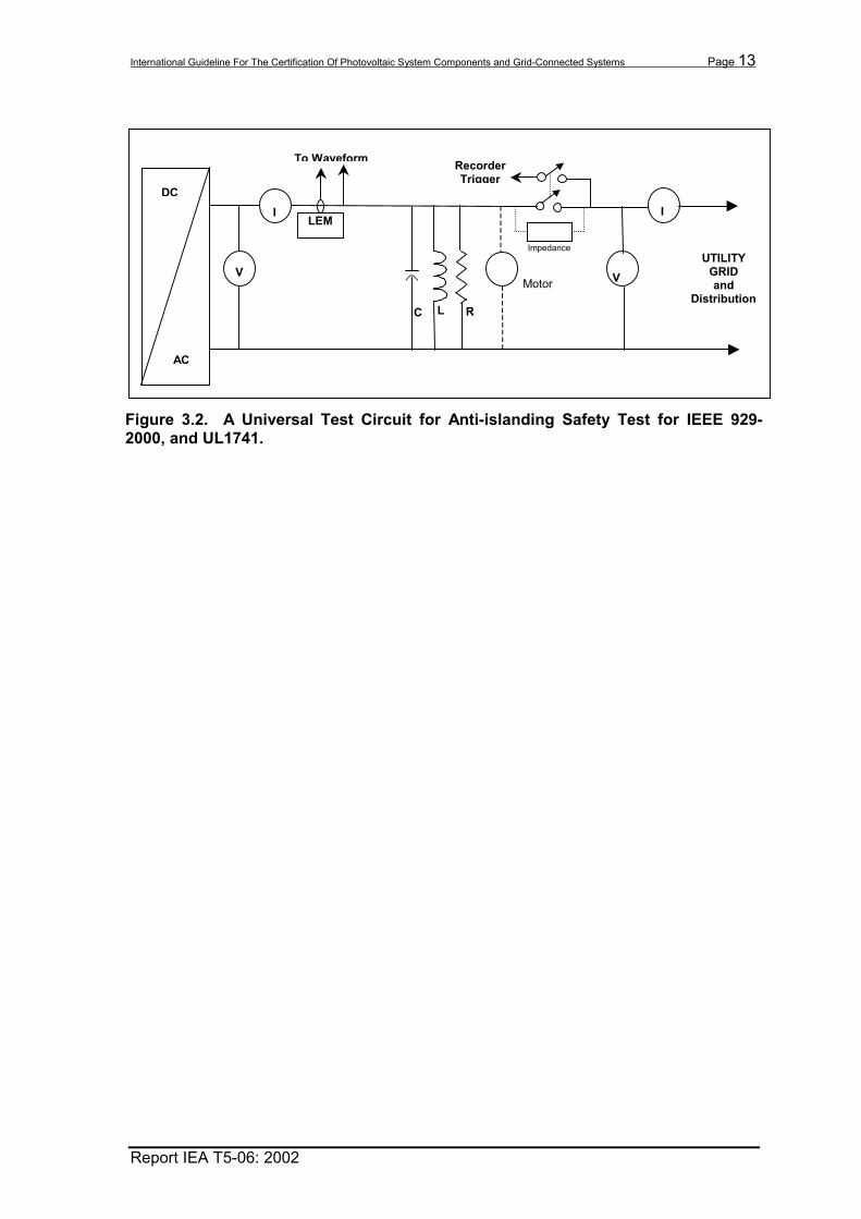
3. SAFETY CONSIDERATIONS Standard electrical system safety practices should be used during the evaluation or testing of grid-interactive inverters and photovoltaic systems. All countries have installation codes and standards that help to assure the safe installation of hardware and systems, however, testing for certification of a system may involve working with a system or component that has wiring errors or unsafe conditions. Only qualified personnel should conduct the tests described in this document. Safe practices must be observed! It is recommended that for each installation, a “Safe Operating Procedure” be written, reviewed and approved before work in the field begins. The “Safe Operating Procedure” must be adhered to at all times. Any changes to the procedure must be reviewed and approved before testing continues. Safe installations are being encouraged by many organizations around the world. Figure 3-1 shows an International Brotherhood of Electrical Workers Training Center for Installer Certification, Sacramento, CA just one of many that will be used to educate and train electrical workers about the photovoltaic technology and the issues associated with current-limited PV source circuits and interconnect issues with utility grids. Figure 3-2 shows a block diagram of a typical test setup to measure the characteristics and especially the anti-island detection circuits in PV inverters.
Figure 3-1. International Brotherhood of Electrical Workers Training Center for Installer Certification, Sacramento, CA
International Guideline For The Certification Of Photovoltaic System Components and Grid-Connected Systems Page 13
Report IEA T5-06: 2002
Motor
DC
AC
V
I
I
R
UTILITY GRID and
Distribution fL C
LEM
To Waveform Recorder
Trigger
V
Impedance
Figure 3.2. A Universal Test Circuit for Anti-islanding Safety Test for IEEE 929-2000, and UL1741.

International Guideline For The Certification Of Photovoltaic System Components and Grid-Connected Systems Page 14
Report IEA T5-06: 2002
4. BACKGROUND AND TEST OVERVIEW Input into this document is based on the results of surveys of participating-IEA countries, installers and manufacturers and a compilation of available international and domestic standards for photovoltaic components and systems. Scientists and engineers from Sandia National Laboratories, Endecon Engineering (Mr. Chuck Whitaker) and the New Mexico State University Southwest Technology Development Institute also provided input for the test procedures. The tests and criteria described in Section 5 were chosen to test systems from the photovoltaic array through the system to the inverter in a utility-interactive photovoltaic system. Tests will be for compliance with specifications and to evaluate the photovoltaic array operation, the inverter operation, and its safety or performance in the system. Suggested sequences for the tests are described below.
4.1 System Size
Test procedures and criteria are often a function of the size of the system or inverter being tested. For simplicity, three sizes are categorized within this document, which are roughly defined as:
Small = 10 kW or less with single-phase output Medium = 10 kW to 100 kW with three-phase output Large = 100 kW with three-phase output that may employ internal protection and required utility relay protection.
These size specifications are meant to provide general guidelines for testing and not to restrict testing to distinct categories.
4.2 Testing Considerations
Determining which of the tests described in this document should be performed will depend on many factors. Some tests may be required by the utility. Other tests may be standard practice of the buyer or installation contractor. Still other tests may be administered to verify a new product or installation procedure or when shipping or installation damage is suspected. Personnel doing the installation may complete many of the tests. In other cases, certified factory test results may suffice in lieu of testing in the field. Note: This guideline lists applicable tests for certification but it is not intended to suggest that all of the tests in this document be performed in the field. Many specific tests that are applicable to and necessary for a particular system will be part of component listing or certification and do not need to be repeated for system certification. Some testing should always be performed before attempting to parallel with the utility grid. Utility power (other than temporary construction power for the system) may only be available after the necessary tests and the pre-parallel inspection have been passed. As system components and installation procedures become more standardized, the amount of testing will be minimized. For example, the installation electrician should eventually do the testing needed for small residential systems as part of his or her standard installation practice or procedures. However, that level of confidence will come only after buyer or third party testing has shown that the system, components, installation procedures, and installation personnel are proven to be adequate for similar installations.

International Guideline For The Certification Of Photovoltaic System Components and Grid-Connected Systems Page 15
Report IEA T5-06: 2002
Requirements for utility interconnection will vary by system size, location, and the participating utility. Small systems that are installed in accordance with applicable interconnect requirements such as IEEE Std. 929-2000 and using listed or certified equipment and a qualified installer should eventually be subject to little or no utility- or owner-witnessed testing. For medium and large systems, the utility may require field verification of safety, performance and protection set points. Section 5 provides the recommended procedure for each item of inspection, test, or calibration. Exact procedures and evaluation criteria may have to be modified based on system size and local requirements, and by referring to the manufacturer's instructions, data sheets, specification, drawings, and other applicable documentation. Some tests may be performed periodically over the life of the photovoltaic system to ensure that reliable and safe operation is maintained and that proper maintenance is performed. The system owner should retain factory-certification test reports for major equipment such as custom transformers, switchgear, inverters, drive motors, tracking controllers, instrument transformers, etc. The manufacturer's certified Test and Calibration reports for major equipment may eliminate the need for field-testing of these components. Table 4-1 suggests appropriate tests for various situations. The first column, “Test #”, refers to the section that describes the test procedure. Figure 4-1 shows some of the collaborative testing performed by IEA participants for harmonics delivered by an inverter. The collective experience of many of the participants helped to determine the tests and test priorities in this document.
Figure 4.1. Task V Experts Conducting Harmonic Tests at The Rokko Island Test Facility, Japan.

International Guideline For The Certification Of Photovoltaic System Components and Grid-Connected Systems Page 16
Report IEA T5-06: 2002
Table 4-1. PV Component/System Test Applicability for Certification and Re-certification ≤≤≤≤10 kW 10-100 kW ≥≥≥≥100 kW
Test #
Test Title Page
#
Inst
alla
tion
Perio
dic
Insp
ectio
n
Inst
alla
tion
Perio
dic
Insp
ectio
n
Inst
alla
tion
Perio
dic
Insp
ectio
n
Array Tests: 5.1.1 Field Wet Resistance Test 22 O O O O 5.1.2 Open-circuit Voltage Test 23 5.1.3 Short-circuit Current Test 25 5.1.4 By-pass Diode Shade Test 26 O O O O 5.1.5 Infrared Scan 27 O O O O O O 5.1.6 Array Tracker Operation Test 28 O O O O O O 5.1.7 Array I-V Curve 28 O O O O O Inverter Tests: 5.2.1 Inverter Initial Inspection 31 5.2.2 Local Inverter Operation and Control 32 5.2.3 Remote Inverter Reset and Disable
Control 33 O O O
5.2.4 Wake-up and sleep operations 33 O O O 5.2.5 Smoke Detector 33 N/A O O O 5.2.6 Door Interlock 34 N/A O O O 5.2.7 Over-temperature 34 O O O O 5.2.8 Over/under frequency, Over/U Volts 35 O O O O O 5.2.9 Loss of control power 35 O O O O O 5.2.10 Loss of array 35 O O O O O 5.2.11 Anti-Islanding 36 O O O O O O 5.2.12 Array Utilization/Maximum Power Point
Tracking 37 O O O
5.2.13 Harmonic Distortion 37 O O O 5.2.14 Power Factor 38 O O O 5.2.15 DC Injection 38 O O O 5.2.16 Phase Current Balance 39 N/A O O 5.2.17 Multiple Inverter Operation 39 O O Instrumentation Tests: 5.3.1 Instrumentation Check 40 O O O O 5.3.2 Instrument Transformers, Current 40 O O 5.3.3 Instrument Transformers, Voltage 41 O O 5.3.4 Instrumentation Calibration 41 O O O O O Other Tests: 5.4.1 Field Inspection 42 O 5.4.2 Ground Resistance Test 43 O O O O O 5.4.3 Isolation Transformer 43 O O O O 5.4.4 Circuit Breaker (ac & dc) 44 O O O 5.4.5 Disconnect Switch 45 O O O 5.4.6 Protective Functions 45 O O O 5.4.7 Wires, Cables 46 O O O O 5.4.8 DC Ground-fault Equipment 47 O O O O O 5.4.9 System Performance 47 O O O O
- Suggested Tests or Required Documentation; O -Optional Tests (samples on multiple systems); -Test Performed for listing/safety by Accredited Laboratories giving transferred documentation.

International Guideline For The Certification Of Photovoltaic System Components and Grid-Connected Systems Page 17
Report IEA T5-06: 2002
4.3 Test Sequence for “Small” Systems
As noted previously, small systems (10 kW or less) that are installed in accordance with applicable standards, using listed or certified equipment, and by a qualified installer should be subject to little or no utility-witnessed testing. The tests suggested here should be standard practice of the installation contractor performed as an integral part of construction activities.
4.4 Test Sequence for “Medium and Large” Systems
This section describes a sample test sequence for initial acceptance of a large photovoltaic system, roughly, 100 kW or larger. Smaller systems, between 10 kW and 100 kW will likely have a test sequence that is a selection of tests falling between this sequence and the small residential test sequence. The test sequence described here may be a specified condition of the system installation contract, or may be a part of the contractor’s normal practice. For large systems, it is likely that certified test results would be a required component of the installation contract. This test sequence is based on applicable codes, standards and utility-practices that promote component evaluation to verify the equipment is properly marked and installed, and has not been damaged in shipping or installation.
4.4.1 Tests Prior to Utility Interconnection
Figure 4-2 shows a test sequence scheduled to start after the system has neared completion of construction. These tests are best performed before construction is fully complete since they may require some dismantling of the array or other components. Also, if problems are found with the installation, personnel are still on site, and repairs, modifications and retesting can then be quickly completed.

International Guideline For The Certification Of Photovoltaic System Components and Grid-Connected Systems Page 18
Report IEA T5-06: 2002
Field Inspections (5.4.1, 5.4.2)
Review/Inspection
Field W et Resistance (5.1.1)
Short Circuit/Open Circuit (5.1.2, 5.1.3)
By-Pass Diode Shade (5.1.4)
IR Scan (5.1.5)
Array T racker Operation (5.1.6)
Initial Instrumentation (5.3.1) Isolation T ransformer
(5.4.3)
Circuit Breaker (5.4.4)
Disconnect Switch (5.4.5)
Instrument T ransformer (5.3.2, 5.3.3)
Protective Devices (5.4.6)
Initial Inverter Inspection (5.2.1)
Array IV Curves (5.1.7)
Wires, Cables (5.4.7)
DC Ground Fault Equipment (5.4.8)
Utility Approval to Interconnect
Documentation Review
Figure 4-2. Suggested Sequence of Tests Prior to Utility Connection
DC Side AC Side

International Guideline For The Certification Of Photovoltaic System Components and Grid-Connected Systems Page 19
Report IEA T5-06: 2002
4.4.1.1 Major Equipment (Excluding the Inverter)
The ac and dc side of the sequence listed in Figure 4-2 should be used, where applicable, to functionally test and verify that the switchgear protective features, relays, and safety devices function in accordance with the manufacturers’ specifications and according to the photovoltaic system design criteria.
4.4.1.2 Pre-Utility Interconnection Inspection
Depending on the photovoltaic system size and local utility requirements, a pre-interconnection inspection may be required prior to initial system operation.
4.4.2 Test On Initial Operation
Once approval to interconnect has been received from the utility, but prior to unattended operation of the system, initial startup tests are performed to verify that the control and protection functions work properly. A suggested sequence is shown in Figure 4-3, “Suggested Sequence of Tests for Initial Startup.”
4.4.2.1 Initial Start-up
The test will consist of demonstrating proper functional operation of the control and protective features. The majority of these tests are related to the inverter since most of the system operation and control is via the inverter. In some cases, devices external to the inverter will handle one or more of these features. In such cases, tests should be modified as appropriate to evaluate these devices. These tests include the following, as also described in Section 5:
• Local operation and controls (5.2.2) • Remote reset and disable control (5.2.3) • Wake-up and sleep operations (5.2.4) • Smoke Alarm (5.2.5) • Door Interlock (5.2.6) • Over-temperature (5.2.7) • Over/under-frequency, Over/under-voltage (5.2.8) • Loss of control power (5.2.9) • Loss of array (5.2.10) • Islanding Detection (5.2.11) • Array Utilization/Maximum Power Point Tracking (5.2.12)

International Guideline For The Certification Of Photovoltaic System Components and Grid-Connected Systems Page 20
Report IEA T5-06: 2002
Instrumentation Test and Calibration (5.3.4)
Measure Harmonic Distortion (5.2.13)
Measure Power Factor (5.2.14)
Measure DC Injection (5.2.15)
Measure Phase Current Balance (5.2.16)
Multiple Inverter Operation (Where Applicable) (5.2.17)
Measure System Performance (5.4.9)
Utility Approval to Interconnect
Inverter and Other Equipment Operational Tests (5.2.2-5.2.10)
Verify Component Compatibility
Interconnection Completed
Begin Period of System Conditioning
Measure Peak Power Tracking Accuracy (5.2.12)
End Conditioning Period
Provide System Rating (Optional)
System Certified
Figure 4-3. Suggested Sequence of Tests on Initial Startup.

International Guideline For The Certification Of Photovoltaic System Components and Grid-Connected Systems Page 21
Report IEA T5-06: 2002
Many of these tests may not be necessary for listed or certified inverters. They are, however, appropriate for large or relatively new inverter models that lack a listing, certification or sufficient operational history. They may also be used as part of a maintenance procedure to evaluate long-term reliability or to help locate problems.
4.4.2.2 Power Quality and System Operation
In a typical acceptance test sequence, “a conditioning period”1 would begin and the tests shown in middle part of Figure 4-3 would be performed. Upon successful completion of these tests, the system would be interconnected and the performance measurement period would commence. A typical grid-connected system is shown in Figure 4-4 below. Power quality measurements/tests should be performed at the point-of-interconnection or the point of common coupling (PCC) with the utility grid. These tests are typically performed after the system has been approved for unattended operation. As with the inverter operational tests, the following may not be necessary for listed inverters. These tests are appropriate for relatively new inverter models that lack sufficient operational history. They may also be used as part of a maintenance procedure to evaluate long-term reliability or to help locate problems. • Harmonic Distortion (5.2.13) • Power Factor (5.2.14) • DC Injection (5.2.15) • Phase Current Balance (5.2.16) • Operation with other inverters in parallel (5.2.17) • Final Instrumentation Test and Calibration (5.3.1through 5.3.4) • System Performance (5.4.9)
1 The conditioning period should allow sufficient time to ensure proper operation of the
photovoltaic system, perform the various inverter and system operational tests and to check and calibrate any instrumentation. It should also allow a significant portion of the initial light-induced photovoltaic device degradation to occur prior to rating the system.
PV array Inverter
Utility
Utility Circuit Interrupting Device PCC
Transformer
Figure 4-4. Typical Grid Connected PV System
Customer Load
PV Interface
International Guideline For The Certification Of Photovoltaic System Components and Grid-Connected Systems Page 22
Report IEA T5-06: 2002
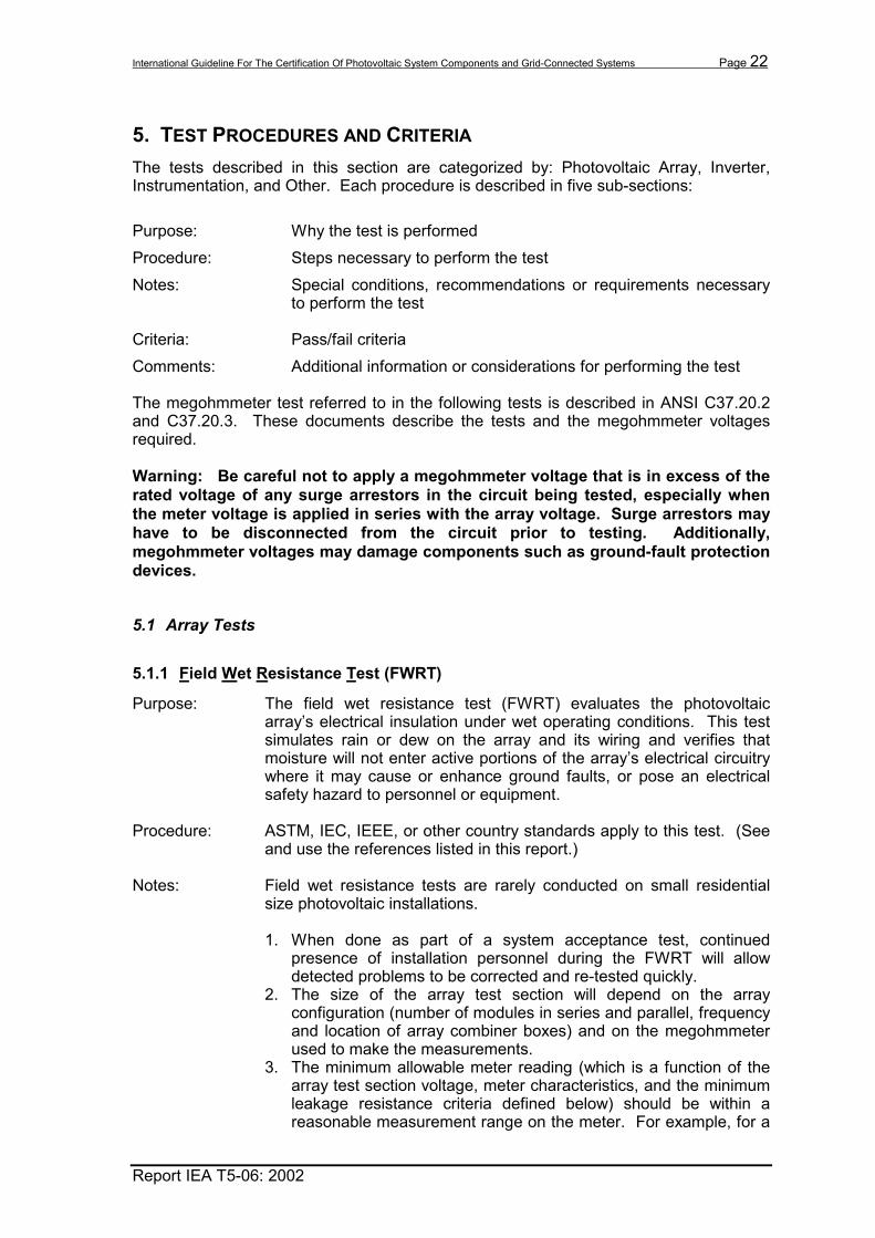
5. TEST PROCEDURES AND CRITERIA The tests described in this section are categorized by: Photovoltaic Array, Inverter, Instrumentation, and Other. Each procedure is described in five sub-sections: Purpose: Why the test is performed Procedure: Steps necessary to perform the test Notes: Special conditions, recommendations or requirements necessary
to perform the test Criteria: Pass/fail criteria Comments: Additional information or considerations for performing the test The megohmmeter test referred to in the following tests is described in ANSI C37.20.2 and C37.20.3. These documents describe the tests and the megohmmeter voltages required. Warning: Be careful not to apply a megohmmeter voltage that is in excess of the rated voltage of any surge arrestors in the circuit being tested, especially when the meter voltage is applied in series with the array voltage. Surge arrestors may have to be disconnected from the circuit prior to testing. Additionally, megohmmeter voltages may damage components such as ground-fault protection devices.
5.1 Array Tests
5.1.1 Field Wet Resistance Test (FWRT)
Purpose: The field wet resistance test (FWRT) evaluates the photovoltaic array’s electrical insulation under wet operating conditions. This test simulates rain or dew on the array and its wiring and verifies that moisture will not enter active portions of the array’s electrical circuitry where it may cause or enhance ground faults, or pose an electrical safety hazard to personnel or equipment.
Procedure: ASTM, IEC, IEEE, or other country standards apply to this test. (See
and use the references listed in this report.)
Notes: Field wet resistance tests are rarely conducted on small residential size photovoltaic installations. 1. When done as part of a system acceptance test, continued
presence of installation personnel during the FWRT will allow detected problems to be corrected and re-tested quickly.
2. The size of the array test section will depend on the array configuration (number of modules in series and parallel, frequency and location of array combiner boxes) and on the megohmmeter used to make the measurements.
3. The minimum allowable meter reading (which is a function of the array test section voltage, meter characteristics, and the minimum leakage resistance criteria defined below) should be within a reasonable measurement range on the meter. For example, for a
International Guideline For The Certification Of Photovoltaic System Components and Grid-Connected Systems Page 23
Report IEA T5-06: 2002
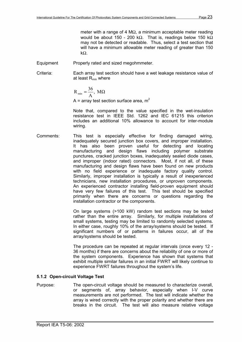
meter with a range of 4 MΩ, a minimum acceptable meter reading would be about 150 - 200 kΩ. That is, readings below 150 kΩ may not be detected or readable. Thus, select a test section that will have a minimum allowable meter reading of greater than 150 kΩ.
Equipment Properly rated and sized megohmmeter.
Criteria: Each array test section should have a wet leakage resistance value of
at least Rmin where
MΩ ,A36R min =
A = array test section surface area, m2 Note that, compared to the value specified in the wet-insulation resistance test in IEEE Std. 1262 and IEC 61215 this criterion includes an additional 10% allowance to account for inter-module wiring.
Comments: This test is especially effective for finding damaged wiring, inadequately secured junction box covers, and improper installation. It has also been proven useful for detecting and locating manufacturing and design flaws including polymer substrate punctures, cracked junction boxes, inadequately sealed diode cases, and improper (indoor rated) connectors. Most, if not all, of these manufacturing and design flaws have been found on new products with no field experience or inadequate factory quality control. Similarly, improper installation is typically a result of inexperienced technicians, new installation procedures, or unproven components. An experienced contractor installing field-proven equipment should have very few failures of this test. This test should be specified primarily when there are concerns or questions regarding the installation contractor or the components. On large systems (>100 kW) random test sections may be tested rather than the entire array. Similarly, for multiple installations of small systems, testing may be limited to randomly selected systems. In either case, roughly 10% of the array/systems should be tested. If significant numbers of or patterns in failures occur, all of the array/systems should be tested. The procedure can be repeated at regular intervals (once every 12 - 36 months) if there are concerns about the reliability of one or more of the system components. Experience has shown that systems that exhibit multiple similar failures in an initial FWRT will likely continue to experience FWRT failures throughout the system’s life.
5.1.2 Open-circuit Voltage Test
Purpose: The open-circuit voltage should be measured to characterize overall, or segments of, array behavior, especially when I-V curve measurements are not performed. The test will indicate whether the array is wired correctly with the proper polarity and whether there are breaks in the circuit. The test will also measure relative voltage

International Guideline For The Certification Of Photovoltaic System Components and Grid-Connected Systems Page 24
Report IEA T5-06: 2002
values of each segment or string of the array before they are connected together.
Procedure: The open-circuit voltage (Voc) of the array or array segment may be measured at any time of the (reasonably bright or sunny) day with a voltmeter that has suitable voltage rating and a typical accuracy of at least 0.5%. The temperature of the back of a representative number of modules should be checked for consistency and the temperature(s) should be recorded with each measurement of voltage. This measurement may be done most conveniently by operating the array-disconnect at each inverter. The system electrical diagram should be studied to determine a measurement point that will be adequately isolated from other array segments. The line-to-line Voc should be equal to the Voc rating of the module (adjusted to actual module temperature) times the number of modules connected in series within the test segment. The measured and rated back-of-module temperatures are used with the module manufacturer's voltage temperature coefficient (β) in equation (1) below to determine the expected voltage at the measured conditions.
( )[ ]REFmodmodREFocexpectedoc TTVnV ,,, 1 −⋅+⋅⋅= β (1) Where: n = number of modules in series in test segment Voc,expected = expected open-circuit voltage of the test segment Voc, REF = module nameplate open-circuit voltage at reference
conditions β = module Voc temperature coefficient,°C-1 Tmod = measured back of module temperature, °C Tmod, REF = back of module temperature at (nameplate) reference
conditions, °C Notes: 1. Voc of crystalline silicon photovoltaic cells is relatively insensitive to
changes in irradiance above a level of about 500 W/m2. All measurements should therefore be made at or above this level.
2. Voc of other photovoltaic cell technologies may be more sensitive to irradiance or to other conditions such as spectral content. Additional constraints may have to be observed or modifications made to equation (1).
3. Voltages less than the expected value may indicate a partial line-to-line or line-to ground fault that is absorbing power. Failed surge arrestors, shorted or damaged insulation on cables, and conduits filled with water may cause low voltage readings.
4. High voltage readings at standard operating conditions are usually the result of wiring errors.
5. Line-to-ground voltages in bipolar arrays should be relatively balanced around zero with one line above zero (positive) and one line below zero (negative). On a center-grounded array, the voltage between the center-conductor and ground should be less than 3% of Voc.
6. Unbalanced voltages can indicate incorrect wiring, ground faults in the wiring or modules, or failure of a surge arrestor.

International Guideline For The Certification Of Photovoltaic System Components and Grid-Connected Systems Page 25
Report IEA T5-06: 2002
7. Note that Voc on all photovoltaic modules degrades over time, though some technologies degrade more rapidly than do others. This fact should be considered when testing older systems.
Criteria: If the measured Voc differs significantly (more than 5%) from Voc,expected
or from other identical circuits, the test segment wiring should be carefully examined and the cause determined.
Comments: This test can be done in lieu of, or complementary to, I-V curve measurements that are described in 5.1.7. This test may be performed on selected array segments in addition to I-V curves to verify performance of the I-V curve test equipment. When a system shows signs of array problems, low monthly energy for example, open-circuit voltage measurements and short-circuit current measurements (described in Section 5.1.3) are simple diagnostic steps that can assist with troubleshooting efforts.
5.1.3 Short-circuit Current Test
Purpose: The short circuit current of array strings, segments or the entire array should be measured to characterize array behavior especially when I-V curve tests are not performed. Measurements of irradiance should be made at the same time.
Procedure: The short circuit current (Isc) of an array or test segment is measured by connecting a low resistance measurement device between the negative and positive legs of the test segment. For very small arrays, Isc can be measured directly with a handheld multi-meter (typically up to 10 Amps). For larger arrays, a special shorting circuit consisting of a conductor, disconnect switch, and current sensor is needed. The current sensor may be a resistive current shunt, a hall-effect device, or other means. All of these components must be sized and rated for the maximum Isc and Voc. CAUTION! Care should be taken when opening a shorted array. Only load break switches or circuit breakers with adequate current and voltage ratings should be used. A short-circuit placed across either of the positive or negative outputs of a bipolar array will cause full array voltage (twice the monopole voltage) to appear across any shorting mechanism or switch when opened. Often these disconnect switches may only be rated for the monopole voltage and may be destroyed when opened under short-circuit conditions at full array voltage. Some other means should be used for shorting the array. The shorting conductor should be disconnected only under no-light conditions (e.g., array covered or darkness) unless it can be completely isolated by appropriately rated disconnect switches. Notes: 1. Isc of the array or array segment should be measured with the
array not shadowed, under clear sky, noontime conditions. 2. The short-circuit current of crystalline silicon-based photovoltaic
devices is relatively insensitive to variations in ambient
International Guideline For The Certification Of Photovoltaic System Components and Grid-Connected Systems Page 26
Report IEA T5-06: 2002
temperature over a wide operating range (-10° to 40° C), increasing slightly with increasing temperature.
3. Other photovoltaic cell technologies may be more sensitive to temperature or to other conditions such as spectral content. Additional constraints may have to be observed or modifications made to equation (2).
4. Low Isc measurements can indicate the presence of circulating ground-fault currents in the array due to multiple ground faults or shadowing. This may also be true with ungrounded arrays.
5. Higher than expected measurements can indicate an array configuration other than expected or increased irradiance on the array not being sensed by the pyranometer.
6. Note that photovoltaic cells typically respond to changes in irradiance in milliseconds whereas thermopile pyranometers can take several seconds to respond.
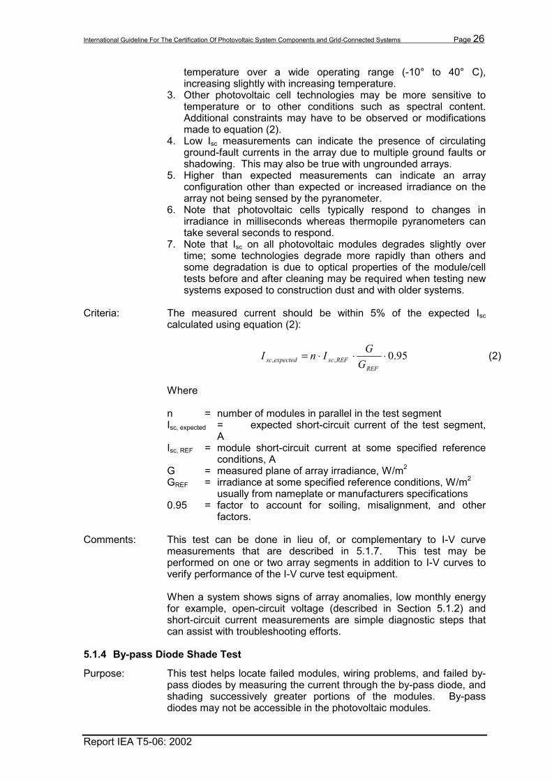
7. Note that Isc on all photovoltaic modules degrades slightly over time; some technologies degrade more rapidly than others and some degradation is due to optical properties of the module/cell tests before and after cleaning may be required when testing new systems exposed to construction dust and with older systems.
Criteria: The measured current should be within 5% of the expected Isc
calculated using equation (2):
95.0,, ⋅⋅⋅=REF
REFscexpectedsc GGInI (2)
Where n = number of modules in parallel in the test segment Isc, expected = expected short-circuit current of the test segment,
A Isc, REF = module short-circuit current at some specified reference
conditions, A G = measured plane of array irradiance, W/m2 GREF = irradiance at some specified reference conditions, W/m2 usually from nameplate or manufacturers specifications 0.95 = factor to account for soiling, misalignment, and other
factors.
Comments: This test can be done in lieu of, or complementary to I-V curve measurements that are described in 5.1.7. This test may be performed on one or two array segments in addition to I-V curves to verify performance of the I-V curve test equipment. When a system shows signs of array anomalies, low monthly energy for example, open-circuit voltage (described in Section 5.1.2) and short-circuit current measurements are simple diagnostic steps that can assist with troubleshooting efforts.
5.1.4 By-pass Diode Shade Test
Purpose: This test helps locate failed modules, wiring problems, and failed by-pass diodes by measuring the current through the by-pass diode, and shading successively greater portions of the modules. By-pass diodes may not be accessible in the photovoltaic modules.
International Guideline For The Certification Of Photovoltaic System Components and Grid-Connected Systems Page 27
Report IEA T5-06: 2002
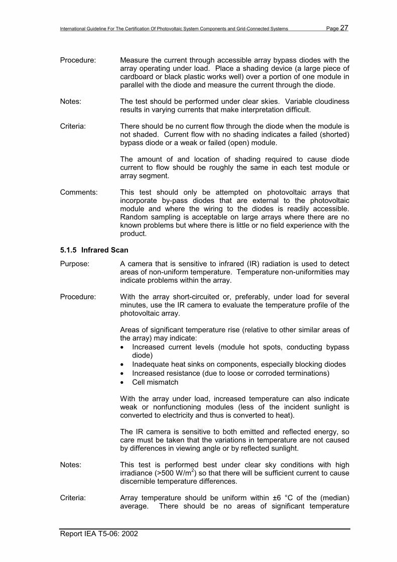
Procedure: Measure the current through accessible array bypass diodes with the
array operating under load. Place a shading device (a large piece of cardboard or black plastic works well) over a portion of one module in parallel with the diode and measure the current through the diode.
Notes: The test should be performed under clear skies. Variable cloudiness results in varying currents that make interpretation difficult.
Criteria: There should be no current flow through the diode when the module is not shaded. Current flow with no shading indicates a failed (shorted) bypass diode or a weak or failed (open) module. The amount of and location of shading required to cause diode current to flow should be roughly the same in each test module or array segment.
Comments: This test should only be attempted on photovoltaic arrays that incorporate by-pass diodes that are external to the photovoltaic module and where the wiring to the diodes is readily accessible. Random sampling is acceptable on large arrays where there are no known problems but where there is little or no field experience with the product.
5.1.5 Infrared Scan
Purpose: A camera that is sensitive to infrared (IR) radiation is used to detect areas of non-uniform temperature. Temperature non-uniformities may indicate problems within the array.
Procedure: With the array short-circuited or, preferably, under load for several minutes, use the IR camera to evaluate the temperature profile of the photovoltaic array. Areas of significant temperature rise (relative to other similar areas of the array) may indicate: • Increased current levels (module hot spots, conducting bypass
diode) • Inadequate heat sinks on components, especially blocking diodes • Increased resistance (due to loose or corroded terminations) • Cell mismatch With the array under load, increased temperature can also indicate weak or nonfunctioning modules (less of the incident sunlight is converted to electricity and thus is converted to heat). The IR camera is sensitive to both emitted and reflected energy, so care must be taken that the variations in temperature are not caused by differences in viewing angle or by reflected sunlight.
Notes: This test is performed best under clear sky conditions with high irradiance (>500 W/m2) so that there will be sufficient current to cause discernible temperature differences.
Criteria: Array temperature should be uniform within ±6 °C of the (median)
average. There should be no areas of significant temperature

International Guideline For The Certification Of Photovoltaic System Components and Grid-Connected Systems Page 28
Report IEA T5-06: 2002
difference. Document areas of temperature extremes, and investigate for possible component or wiring problems.
Comments: This test is an easy way of quickly evaluating a large array or a large number of small systems. A chief advantage is that it can be performed without disturbing an operating system. However, IR cameras are expensive and delicate test instruments requiring proper calibration to provide adequate results. Interpreting the results may take some practice as well. An experienced operator that has experience in using the equipment and in evaluating photovoltaic systems should perform the test. Many utilities use IR cameras for a variety of activities from power plant maintenance to customer energy savings programs, hence the equipment may be available for this purpose.
5.1.6 Array Tracker Operation Test
Purpose: Verify the operation and performance of array tracking structures in accordance with manufacturer specifications and system requirements.
Procedure: Operation and accuracy of array tracking mechanisms should be tested on arrays so equipped. Items to test may include: • Wake up and Sleep (Stow) operations • Tracking accuracy under normal conditions • Tracking accuracy under abnormal conditions (e.g., cold weather,
high wind, etc.) • High-wind stow • Travel limit devices Under manual operation, the tracker limit switches should be checked for proper alignment and adjustment such that physical tracking limitations are not exceeded. Install clinometers on the tracker and monitor tracker position over some period of time. Compare actual array position to a calculated position based on time, date, and location. Repeat under various conditions.
Criteria: Proper operation and performance to manufacturer's specifications should be demonstrated.
Comments: The tracking accuracy required for flat plate modules is, in most cases, significantly less than that required for concentrator systems. For tracking systems that utilize untested mechanical components or control hardware or software, a full test of the system may need to be performed. For systems utilizing proven equipment and software, travel limit and wind stow devices may be sample tested to provide assurance of their operation.
5.1.7 Array I-V Curve
Purpose: I-V curves are useful for identifying array problems and characterizing array performance. Figure 5-1 shows an example of wiring, field J-

International Guideline For The Certification Of Photovoltaic System Components and Grid-Connected Systems Page 29
Report IEA T5-06: 2002
boxes and combiner box where fuses may be pulled in order to conduct sub-array I-V curve tests
Figure 5.1. Example of a PV array wiring diagram showing disconnect locations with fuses and circuit breakers Procedure: Disconnect the array from the inverter (a dc disconnect switch may
suffice). [DANGER, HIGH VOLTAGE!] Connect the curve tracer load to the array leads carefully following the curve tracer operating instructions (be aware of array and load polarities). Sweep the load such that it operates the array over its range of Voc and Isc (or as the load will allow). Record voltage and current readings for at least 10 steps. Array I-V curves require a variable load to sweep the array through its range or operation and measurement equipment to record the current-voltage pairs. The variable load might be a decade resistor box, a programmable load, or a capacitor-based I-V curve tracer. Some inverters are capable of operating the array at a user-specified voltage or current. These inverters can also be used to sweep an I-V curve. The rate at which the load sweeps the curve can impact the accuracy of the resulting curve. If the rate is too low, changes in sun intensity can occur. If the rate is too fast, some cell technologies (those with high minority carrier lifetimes, for example) may not have sufficient time to fully respond to the change in voltage.
#8 AWG 32A
Source Circuit
1
20A
20A
20A
20A
20A
20A
#10 AWG 16A
#8 AWG 32A
#8 AWG 32A
40A
40A
40A
Class T Fuses
120A
96 amps #1 AWG
Fuses
Field J Box
#10 AWG 16A
#10 AWG 16A
#10 AWG 16A
#10 AWG 16A
#10 AWG 16A
DC Combiner/Disconnect Box
Pull-out Fuse Holder
Source Circuit
2
Source Circuit
3
Source Circuit
4
Source Circuit
5
Source Circuit
6

International Guideline For The Certification Of Photovoltaic System Components and Grid-Connected Systems Page 30
Report IEA T5-06: 2002
Along with the series of current-voltage pairs, array and ambient conditions should be recorded for each curve including: • Irradiance (of the appropriate components and orientation) • Module Temperature • Ambient Temperature • Wind Speed • Date and Time An indication of irradiance stability, such as pre- and post-curve irradiance, can also be recorded and is especially important if the I-V curve measurement takes more than 1 second2. Site latitude and longitude are also necessary for performing angle-of-incidence and air mass (spectral) corrections (see 5.4.9). The measurement equipment must be capable of monitoring the array with sufficient speed and accuracy. During the curve sweep, typically only the array current and voltage are measured, with irradiance stability measurements taken before and after the curve, and the remaining parameters measured once before or after the curve.
Notes: I-V curves should be taken under clear sky, relatively stable conditions. For performance measurement purposes, there are a number of factors that can reduce (or enhance!) the measured performance that are not necessarily indicators of array problems: • Irradiance, temperature (array and ambient), wind speed • Spectral content (air mass is a good indicator) • Solar incidence angle • Soiling • Shading (if any) • Cloud-edge effects Some testers are very sensitive to any capacitive or inductive components in the circuit with the photovoltaic array (for example filter circuitry in the inverter). It is often necessary to completely isolate the positive, negative, and neutral legs of the photovoltaic array from the inverter before measuring the curve.
Criteria: The array segment Voc and Isc should meet the criteria defined in sections 5.1.2 and 5.1.3 respectively. Segment fill factor and peak power should meet the requirements specified by the module manufacturer or system supplier. All I-V curves should be similar in shape (other than differences due to changes in irradiance or temperature).
Comments: An I-V curve measurement of the photovoltaic array or array segment,
as practical, may be performed in-lieu of, or in addition to, the open-circuit and short-circuit tests described in sections 5.1.2 and 5.1.3 for diagnostic purposes. Periodic I-V curves on an unmonitored
2 Measurements have shown that under partly cloudy, windy conditions, irradiance can change
at more than 200 W/m2/sec. Irradiance stability should be measured with a fast response device such as a photovoltaic cell as opposed to a thermopile pyranometer, which responds relatively slowly.

International Guideline For The Certification Of Photovoltaic System Components and Grid-Connected Systems Page 31
Report IEA T5-06: 2002
photovoltaic system can show changes in the array performance that might indicate the emergence of an array-related problem. Examples of I-V curve anomalies include fill factor voltages, or currents outside expected limits or bumps on the curve indicating bypass diode conduction and a related array problem. The curves can also help to locate deficient array segments that indicate either out-of-tolerance module performance or other possible problems. Bumps (erratic changes in slope) in the curve may indicate weak array segments, loose connections and/or conducting bypass diodes. Weak segments may be due to defective or under performing modules, shading, wiring problems, or tracker problems. Note that some loads may not be capable of operating the array at short-circuit or open-circuit. A resistive load, for example, even in a shorted condition will have some resistance due to the shorting bar and connecting leads. A bi-polar power supply capable of sinking and sourcing can be operated such that the voltage at the array terminals is zero. Capacitive loads may also incorporate a negative pre-charge that will start the sweep with the array slightly reverse biased.
5.2 Inverter Tests
Example of a Grid-Tied PV System
AC Loads
Utility Grid Inverter PV
Array
Disconnects/Fuses
PCC
Surge Suppression
System Ground When Used
Figure 5-2. Grid-tied PV System Showing Locations of Disconnects, PCC and Surge Suppression
5.2.1 Inverter Initial Inspection
Purpose: Verify proper installation and basic safety functionality prior to interconnection with the utility. Refer to Figure 5-2 for locations of disconnects, fuses, the point of common coupling, surge protection and system grounds (when used).

International Guideline For The Certification Of Photovoltaic System Components and Grid-Connected Systems Page 32
Report IEA T5-06: 2002
Procedure: After the inverter(s) and necessary accessory equipment/devices are installed in their final configuration, but prior to paralleling with the grid, perform a visual inspection of wiring, components, enclosure, etc. Verify the operation of emergency stop and other controls (as possible). Check for adequacy of system grounds. Verify equipment grounds are in place and connected.
Criteria: The Initial Inverter Inspection should show no unexplained deviations between design drawings and the as-built and installed configuration. Check all wiring insulation for fraying caused by shipping. All connections should be tight (per manufacturers specifications, if applicable). All functional tests should show normal operation.
Comments: Generally inverter or control functions are not present without utility input.
5.2.2 Local Inverter Operation and Control
Purpose: Verify the operation of the systems local control functions.
Procedure: Local operation may include such features as: • Startup • Shutdown • Emergency Stop • Peak Power Tracking/Fixed Voltage Operation Start with the inverter in shutdown mode. Ensure that the photovoltaic array is connected and operational, that there is sufficient sunlight to operate the inverter, and that the ac and dc contactors and disconnects are closed. Press the Startup button (or otherwise activate this control function). Next, activate the Shutdown control. Restart the unit and test the Emergency Stop control. Perform these emergency stops over a range of power levels and record results for each test.
Notes: 1. The Emergency Stop function can be a harsh method of shutting
down the inverter since it may not allow for normal orderly shutdown sequences. In some cases, protective fusing or circuit breakers may trip.
2. If provided, test the unit’s “Fixed Voltage” control. Switch the unit from peak power tracking to fixed voltage operation and sweep the fixed voltage control through its range of operation recording the operating range.
3. Record the inverter’s response and changes in annunciations or displays, operation of relays or contactors, and the approximate time between each change to each of these control functions.
Criteria: Controls should operate as stated in the procurement or manufacturer
specifications.
Comments: This test should be performed on all systems. It is likely that the installation personnel will have performed this test.

International Guideline For The Certification Of Photovoltaic System Components and Grid-Connected Systems Page 33
Report IEA T5-06: 2002
5.2.3 Remote Inverter Reset and Disable Control
Purpose: Verify the operation of the system’s remote control functions.
Procedure: Test the remote disable and reset functions as in the previous tests with the remote control functions connected and operational or by using a simulated signal, noting the response of the inverter in each case.
Notes: If the remote control functions use power-line carrier signals, the required signal strength should be evaluated and compared to typical signal strengths received at the site.
Criteria: Controls should operate as stated in the procurement or manufacturer
specifications.
Comments: Remote functions should be tested on those systems that will utilize this feature.
5.2.4 Wake-up and sleep operations
Purpose: Verify daily automatic wake-up and sleep operations.
Procedure: This test is used to determine the levels of array output and irradiances at which the inverter goes through its normal morning startup and evening shutdown sequences. This test is best done using data acquisition equipment set up to monitor irradiance, array dc voltage and current, and inverter status (if available). For testing inverters that utilize a reference cell to determine an acceptable irradiance level, monitor the irradiance in the plane of the reference cell as well. From data recorded under relatively clear sky conditions, note the irradiance levels, array voltages and currents at which the system starts up and shuts down,
Notes: The losses (inverter tare losses, transformer losses and display losses) in the sleep mode should be documented either from the inverter manufacturer’s specification/certification reports or measured on site.
Criteria: Wake up and sleep operations should occur within the conditions and
tolerances stated in the procurement or manufacturer specifications.
Comments: Determination of the ac and dc conditions that trigger system wake-up or sleep functions are primarily intended for large systems where the potential loss of revenue justifies the expense of the test, or in prototyped systems that need to be characterized.
5.2.5 Smoke Detector
Purpose: Verify system response to smoke when applicable.
Procedure: Verify that the inverter trips off-line when a quantity of smoke is released in the unit, when the smoke detector’s output contacts are shorted or opened, or when the smoke detector's test button is pressed.

International Guideline For The Certification Of Photovoltaic System Components and Grid-Connected Systems Page 34
Report IEA T5-06: 2002
Notes: Small inverters rarely use smoke detectors.
Criteria: Smoke detector function should operate as stated in the procurement or manufacturer's specifications.
Comments: Smoke is available in aerosol can form specifically to test smoke alarms. Smoke alarm function provided within a listed inverter is exempt from this test.
5.2.6 Door Interlock
Purpose: Verify the operation of inverter door interlock feature.
Procedure: With the inverter on-line, verify proper shutdown when the cabinet door(s) is opened.
Notes: Small inverters rarely use interlock devices. Listed equipment generally requires that a tool be needed to gain access to the interior and electrical circuitry. If a tool is not required then an interlock should be installed.
Criteria: Inverter should shutdown when the cabinet door(s) is opened.
Comments: Interlock function provided within a listed inverter is exempt from this test.
5.2.7 Over-temperature
Purpose: Verify the operation of inverter over-temperature feature.
Procedure: Determine if the inverter temperature sensor measures device (such as transistors or insulated-gate bipolar transistors (IGBT)) temperature or air temperature. If it measures device temperature, it may be difficult to heat the sensor sufficiently without damaging the device. If this is the case, the circuit can be tested by disconnecting the temperature sensor (this open condition should cause an over-temperature trip), or by connecting an identical sensor that can be heated. Apply heat to the inverter temperature sensor and verify proper shutdown.
Notes: Many inverters use both temperature related power fold-back (power limiting) and an over-temperature sensor for self-protection. The fold-back function is useful to keep the system operating when temperatures are high but may also result in poor system performance if improperly designed.
Criteria: Inverter should shutdown at the temperature stated in the procurement or manufacturer specifications.
Comments: Over-temperature function provided within a listed inverter is exempt from this test.

International Guideline For The Certification Of Photovoltaic System Components and Grid-Connected Systems Page 35
Report IEA T5-06: 2002
5.2.8 Over/under frequency, Over/under voltage
Purpose: Verify the proper operation of the inverter under out-of-tolerance frequency and voltage conditions.
Procedure: Simulate appropriate signals from the frequency and voltage trip relays, control equipment, or transducers, and verify proper shutdown. Alternatively, adjust the device trip points to the current conditions.
Notes: Many inverters use firmware or software that is factory set to control over/under voltage and over/under frequency settings. If improperly set, changing these controls will require changes by the manufacturer. Changing the controls will often violate the listing or certification of the inverter.
Criteria: Controls should operate as stated in the procurement or manufacturer specifications.
Comments: Simulation of over/under voltage must be done with the manufacturer’s oversight or instructions. This is often a difficult test to conduct in the field because specialized equipment and test setup may be necessary. Application of test signals may damage or destroy sensitive logic circuitry.
5.2.9 Loss of control power
Purpose: Verify the proper operation of the inverter under loss of control power.
Procedure: Review manufacturer’s drawings and schematics to determine an appropriate method for interrupting power to the control unit without interrupting the dc input to or ac output from the power section of the inverter. Verify proper shutdown.
Notes: Control power is typically supplied by via the utility power source; however, some inverter designs use the array or battery side to provide the control power. Verify the source of control power before proceeding.
Criteria: Inverter should shutdown in an orderly fashion.
Comments: This test is particularly important for independently powered control systems (for example one controller operating multiple inverters. Listed or previously certified inverters with integral controllers are exempt from this test.
5.2.10 Loss of array
Purpose: Verify the proper operation of the inverter under loss of array power condition.
Procedure: With the system operating normally, the array input is disconnected and inverter response is recorded. A load-break disconnect switch or circuit breaker is needed between the array and the inverter. This device will be used to interrupt the dc current in to the inverter. Though such a device is typically required

International Guideline For The Certification Of Photovoltaic System Components and Grid-Connected Systems Page 36
Report IEA T5-06: 2002
by local codes, under some circumstances it may not be a permanent component of the system. It may only be installed during this test, and removed afterwards, if not required. The intent is to use a device that is independent of the inverter controls.
Notes: Loss of array power should not create any unsafe conditions such as loss of ground or unexpected connections to energized capacitors within the inverter.
Criteria: Inverter should react as stated in the procurement or manufacturer specifications.
Comments: Listed inverters with integral controllers are exempt from this test.
5.2.11 Anti-Islanding
Purpose: Verify the proper operation of the inverter under loss of utility condition.
Procedure: In this test, the time it takes for the inverter to disconnect from the ac grid after loss of utility voltage is determined. An oscillograph or other events recorder is used to monitor the line-side ac voltage and the inverter ac contactor status. If multiple inverters are connected to the grid in near proximity, this test should be performed one inverter at a time and then with all inverters operational. The point at which the loss of utility is to be simulated (i.e. primary side of service transformer) should be on the utility side of the point at which the multiple inverters are interconnected.
The length of islanding or run-on time may be related to relative levels of loads and system output(s) on the section of isolated grid. The impedance of the local grid may also influence anti-islanding tests. Remove or shutdown all nonessential loads that are on the inverter side of the “loss of utility”. Record nameplate information on any loads that cannot be removed as well as the level of system output (combined output in the case of multiple inverters) at the time of interruption.
Notes: This test requires well-controlled test conditions and utility fluctuations generally unavailable in the field. These tests are typically conducted under laboratory conditions using specified values of loads and reactive loads resulting in documentation that can be transferred to the field.
Criteria: Inverter should shut down within the time specified in IEEE Std. 929-2000 or as required in other national documents or per the utility interconnection requirements.
Comments: Various test circuits have been proposed to allow testing of individual inverters instead of multiple inverters. These test circuits have been determined to be worst case and it is a consensus that inverters that pass anti-islanding tests when connected to these resonant circuits will also detect and island when multiple inverters are attached to the same point of connection. The maximum number of anti-islanding inverters that will function properly when connected to a local distribution has not yet been determined.

International Guideline For The Certification Of Photovoltaic System Components and Grid-Connected Systems Page 37
Report IEA T5-06: 2002
5.2.12 Array Utilization/Maximum Power Point Tracking
Purpose: Verify the operation and effectiveness of the inverter's “Maximum Power Point Tracking” (MPPT) function and the “Array Utilization.”
Procedure: Commonly, photovoltaic systems include equipment (usually in the inverter) that is designed to adjust the array operating voltage to maximize system output. Such equipment should be tested to determine the accuracy of the peak power tracking algorithm and circuitry. This can be done by setting the peak power tracking unit into fixed voltage operation and manually adjusting the array voltage (on devices that offer this feature) to maximize the system output as shown on SCADA or inverter front panel. The resulting voltage can then be compared to the operating voltage achieved by the device under peak power tracking operation. Alternatively, the peak power point for the array can be determined from I-V curves and compared to the peak power tracker's selected array voltage under identical ambient conditions.
Criteria: Array operating voltage and current should be maintained at the maximum power point within the tolerance stated in the procurement or manufacturer specifications.
Comments: This test is intended to verify the operation and accuracy of the peak power tracking circuitry. It may be performed on a new, unproven design or for diagnostic purposes, for example if there is concern that a low system performance is related to the interaction between the inverter and photovoltaic array.
5.2.13 Harmonic Distortion
Purpose: Determine the current and voltage total harmonic distortion (THD) or individual harmonics contributed by the inverter.
Procedure: Connect a power quality measurement device or a spectrum analyzer to the ac output of the inverter, ideally between the inverter and the utility interconnection point. If there is a dedicated transformer at the output of the inverter, make the connection on the utility side of this transformer. Collect current and voltage harmonic distortion data at power levels of 20%, 40%, 80%, and 100% of inverter rating. Distortion criteria are applicable at 100% of inverter rating; thus, measurements are best done during clear sky conditions. When 100% of inverter rating is not possible, then data for the highest attainable power should be taken.
Notes: Measurements are best done during clear sky conditions with power quality measuring equipment or a spectrum analyzer that has a response of at least the 25th harmonic. Many inverters operate with pulse-width-modulation circuits at high frequencies requiring response up to the 50th harmonic.
Criteria: Test per IEEE Std. 519 or other national standards for harmonic content of power generators. For example, the limits for harmonics at full power stated in IEEE Std. 929-2000 are: Current 5% THD, 3% Single Voltage 3% THD, 1% Single

International Guideline For The Certification Of Photovoltaic System Components and Grid-Connected Systems Page 38
Report IEA T5-06: 2002
Below are the criteria from IEEE Std. 929-2000 The photovoltaic system electrical output at the [point of common coupling] between the utility and the photovoltaic system should comply with IEEE Std. 519-1992, Chapter 10 of which is titled “Recommended Practices for Individual Customers” and should be used to define the acceptable harmonic levels for photovoltaic systems connected to a utility. Those requirements are: a) Total demand distortion shall be less than 5% of the fundamental frequency at full
load. b) Odd harmonics less than 11th shall be less than 4.0% of the fundamental frequency. c) Odd harmonics including 11th through 15th shall be less than 2.0% of the
fundamental frequency. d) Odd harmonics including 17th through 21st shall be less than 1.5% of the
fundamental frequency. e) Odd harmonics including 23rd through 33rd shall be less than 0.6% of the
fundamental frequency. f) Odd harmonics above the 33rd shall be less than 0.3% of the fundamental frequency. g) Even harmonics shall be less than 25% of the odd harmonic limits listed above.
Comments: Listed or previously certified inverters with integral controllers are
exempt from this test when appropriate documentation is available. This test can be done simultaneously with the power factor test using the same equipment.
5.2.14 Power Factor
Purpose: To determine the power factor of the system at different power levels.
Procedure: Connect a power-quality measuring device to the ac output of the inverter, ideally between the inverter and the utility interconnection point. If there is a dedicated transformer at the output of the inverter, make the connection on the utility side of this transformer. Collect power factor data at power levels of 20%, 40%, 80%, and 100% of inverter rating. When 100% of inverter rating is not possible, then, data for the highest attainable power should be taken.
Notes: Measurements are best done during clear sky conditions
Criteria: The power factor should be 0.95 lagging or higher at a power level above 20% of rated power.
Comments: Listed or previously certified inverters with integral controllers are exempt from this test when appropriate documentation is available. This test can be done simultaneously with harmonic distortion test using the same equipment.
5.2.15 DC Injection
Purpose: Determine the magnitude of dc current injected into the utility grid.
Procedure: Connect a device that measures power quality or an oscilloscope with appropriate probes to the ac output of the inverter, ideally between the inverter and the utility interconnection point. Collect data at power levels of 20%, 40%, 80%, and 100% of inverter rating. When 100%

International Guideline For The Certification Of Photovoltaic System Components and Grid-Connected Systems Page 39
Report IEA T5-06: 2002
of inverter rating is not possible, then, data for the highest attainable power should be taken. From the data collected, calculate the magnitude of the dc current and voltage.
Notes: Measurements are best done during clear sky conditions.
Criteria: DC current injection into the utility grid should typically be less than 0.5 percent of full load inverter output current but national standards vary on the allowable value.
Comments: Excessive dc current on the grid can damage attached utility equipment and customer loads. This test is unnecessary for systems with dedicated output transformers. Listed or previously certified inverters with integral controllers are exempt from this test when appropriate documentation is available. This test can be done simultaneously with the harmonic distortion test using the same equipment.
5.2.16 Phase Current Balance
Purpose: Test inverter or system output to determine if phase currents are reasonably balanced and pose no phase balance problem at the point of utility interconnect.
Procedure: If a single inverter is being used for the system, the phase balance is typically measured as part of the inverter listing or certification. If multiple inverters are being connected to different phases of the utility then the total phase current balance must be determined and evaluated with regard to the capacity of the utility feeder and transformer.
Notes: A utility engineer should be present for these tests.
Criteria: Inverter should meet the requirements specified in IEEE Std. 929-2000 or other national standard or the interconnecting utility requirements. Phase current imbalance should be less than 5% measured at 50% and 100% rating.
Comments: Unbalanced phase currents may cause overheating of the utility transformer. Unbalance within an inverter generally indicates a problem.
5.2.17 Multiple Inverter Operation (Optional)
Purpose Harmonic output or line side filtering of one inverter can have an adverse affect on the operation of other inverters. Other inverters that are connected in parallel can affect the system operation and can also influenced inverter output power quality. These effects may occur only under certain conditions such as wake-up and sleep transitions or under low light/low power levels.
Procedure: No procedure is recommended at this time. The need for multiple inverter testing will be based upon the test setup used, the

International Guideline For The Certification Of Photovoltaic System Components and Grid-Connected Systems Page 40
Report IEA T5-06: 2002
impedances of the utility grid and the method of anti-islanding detection used in the inverter.
Notes: Multiple inverter tests are expensive and often do not represent a condition that will occur in a real application. Single inverter tests using the wrong utility impedance or the wrong simulated utility waveforms may produce misleading results.
Criteria: Inverter should operate normally and within specifications with other inverters in parallel.
Comments: Listed inverters have undergone rigorous tests that have been determined to equate to multiple inverter tests. Typically the listed inverters are exempt from the multiple-inverter test, but that is not to say that all conditions (many inverters tied to the same section of the grid) have been proven.
5.3 Instrumentation Tests
5.3.1 Instrumentation Check
Purpose: To check the wiring and installation of instrumentation equipment.
Procedure: Verify that all wires to the data acquisition system (DAS) or Supervisory Control and Data Acquisition (SCADA) are properly terminated. Also, where necessary and possible, simulate control signals such as startup, shutdown, and reset from the DAS or SCADA to the inverter(s) and verify the system's consequent operation.
Notes: Routing of instrumentation wiring must meet applicable standards and codes and must not reside in the same conduit as power cables. Instrumentation cable tied to power cables must be protected with fuses or current limiting impedance.
Criteria: Variable depending upon type of DAS or SCADA.
Comments: DAS and SCADA are usually limited to prototype systems, large utility-owned systems, or special projects. It is especially important to test instrumentation related to revenue metering or performance verification. Utilities that require a SCADA interface may only want output signals and will connect their own equipment to these signals.
5.3.2 Instrument Transformers, Current
Purpose: Verify the performance of instrumentation current transformers (CT)
for intermediate and large systems.
Procedure: A saturation test should be made on all CTs that are used with protective relays or a manufacturer's saturation curve is generally acceptable.

International Guideline For The Certification Of Photovoltaic System Components and Grid-Connected Systems Page 41
Report IEA T5-06: 2002
The ratio of all CT windings should be proven either by using a current source (primary to secondary) or a voltage source (secondary to primary). The CT circuits should be checked for proper connections, polarity, and continuity by applying primary or secondary current and confirming the current at the relays. A single-phase burden check should be made on the phase with the highest burden. The impedance-to-ground of the total circuit with the ground wire lifted should be measured to prove that only one ground point exists.
Notes: CAUTION!: Current Transformers should never be open-circuited under load! The voltage in the CT can rise above its rated value and lead to insulation breakdown. Many installations will include a CT shorting block for this purpose.
Criteria: CT ratios and burdens should be within the manufacturer’s specifications. CT impedance to ground with the ground wire disconnected should exceed 10 MΩ.
Comments: This test should be applied to separate CTs used for system protection.
5.3.3 Instrument Transformers, Voltage
Purpose: Verify the performance of instrumentation potential transformers (PT).
Procedure: A megohmmeter should be used to measure the insulation of the transformer, winding-to-winding and each winding-to-ground. All ratios should be proven either by performing a turns ratio test or a voltage ratio test.
Notes: The potential transformers should be isolated during the course of this test. A test switch (usually 10-pole), commonly installed in the potential transformer circuit, can be used for this purpose.
Criteria: PT insulation resistance readings should meet or exceed the manufacturer’s specification. Typical insulation resistance readings are in excess of 100 MΩ.
Comments: This test should be applied to separate PTs used for system protection or for system monitoring.
5.3.4 Instrumentation Calibration
Purpose: Determine the accuracy of the instrumentation per manufacturer's specifications.
Procedure: Instrumentation can be tested on a component-by-component basis by injecting a known signal and recording the output, or on an instrumentation system basis by comparing output readings to

International Guideline For The Certification Of Photovoltaic System Components and Grid-Connected Systems Page 42
Report IEA T5-06: 2002
independent measurements made with reference equipment traceable to a national institute for standards certification. Calibrate the instrumentation per the instrumentation manufacturer's specification. Adjust calibration coefficients as necessary.
Criteria: Calibrations should meet the manufacturer’s specifications.
Comments: Proper calibration is important for revenue metering, payment-based system ratings, and R&D data.
5.4 Other Tests
5.4.1 Field Inspection
Purpose: Field inspections are performed to evaluate the installation quality and correctness in the photovoltaic system.
Procedure: A general inspection and walk-through of the photovoltaic system should be conducted to verify that the system is built as designed, installed in a workmanlike manner and consistent with industry practice, standards, codes, and operational requirements. Visual, electrical, and mechanical inspections should include, but are not limited to, evaluating and reporting the following where applicable: • Torque of electrical and mechanical bolted connections (spot
check where specified) • Condition of finish or corrosion protection • Integrity of photovoltaic module mechanical and electrical
connections (random) • Damage to photovoltaic modules • Damage to support structures • Integrity of installation and support of electrical cable and conduit
systems • Integrity and completeness of equipment and system grounds • Integrity of seals and bearings (leaking or binding) • Integrity and completeness of wiring • Accuracy of as-built documentation • Installation in compliance with applicable codes and standards
Notes: The results of the tests and observations made during the inspections should be documented. Appropriate corrective actions should be completed for all safety and operational defects and deficiencies identified prior to system startup.
Criteria: Acceptable torque values for bolted electrical and mechanical con-nections should be determined based on system/manufacturer's specifications and design.
Comments: Field inspections should be performed on all systems after construction. Inspections can be performed as construction of subsystems is completed. In general, inspections should be repeated on an annual or semi-annual basis as part of a preventative maintenance program. Torque inspections should be made for new

International Guideline For The Certification Of Photovoltaic System Components and Grid-Connected Systems Page 43
Report IEA T5-06: 2002
installations and it is especially important for inspections to be periodically conducted during the life of the system.
5.4.2 Ground Resistance Test
Purpose: Check and verify the impedance of the system ground grid.
Procedure: Using a “Megger Null Balance Tester” or equivalent, measure the resistance of the grounding system with respect to ground (earth). Representative locations on the array and array structure, and of the system grounding should be tested.
Criteria: The ground grid resistance should be 25 Ω or less. Some site requirements such as communication or substation sites require substantially less ground resistance.
Notes: The test should be performed when the soil is as dry as typically possible.
Comments: Ground grid resistance measurements should always be made on ground-mounted systems larger than 50 kW. When resistance measurements are higher than the criteria stated above, additional ground rods, deeper ground rods, or other means may be used to reduce the resistance as necessary.
5.4.3 Isolation Transformer
Purpose: Check and verify the insulation and turns ratio of the isolation transformer.
Procedure: a) 600 - 25,000 Volt System Measure the insulation resistance to ground of the transformer, winding-to-winding and each winding-to-ground per ANSI C37.20.2 and C37.20.3 or applicable national standards. Multi-tap transformers should be tested on the final operating tap. All ratios should be verified either by performing a turns ratio test or a voltage ratio test. Transformers containing insulating oil should be tested for dielectric strength. b) Below 600 V Open the photovoltaic system side of the transformer, close the utility side and measure the voltage on both sides of the transformer.
Criteria: a) 600 - 25,000 V Insulation resistances to ground should exceed 10 MΩ. All turns or voltage ratios should be as specified. b) Below 600V The voltage measured on the photovoltaic side should be at the anticipated ratio to that measured on the utility side

International Guideline For The Certification Of Photovoltaic System Components and Grid-Connected Systems Page 44
Report IEA T5-06: 2002
Comments: Even for a small residential system, the <600 V test can easily and quickly be performed by the installation electrician during installation. This can help locate faulty, mislabeled, or improperly installed transformers before any equipment is damaged. Isolation transformers included inside the enclosure of listed inverters do not need to be tested.
5.4.4 Circuit Breaker (ac & dc)
Purpose: To verify the operation and performance of circuit breakers
Procedure: For circuit breakers operated by protective relays, apply a variable test voltage to the breaker input ranging from 50% to 100% of the nominal control voltage and note the voltage at which the breaker trips. The insulation resistance to ground of three phase circuit breakers connected to the primary bus bar should be measured per ANSI C37.20 or other applicable national standards in the following manner (refer to Figure 5-3): • Breaker open -- each pole to ground, pole 1 to 4, pole 2 to 5, pole
3 to 6. • Breaker closed -- pole 1 to ground, pole 2-ground, pole 3 to
ground and if the poles are in common tank or cell, pole 1 to 2, pole 2 to 3, pole 3 to 1.
A micro-ohm or continuity test should be performed on all circuit breakers used in circuits above 600V. For systems 600V and below, a continuity check is sufficient. On systems operating at 600 V or higher, insulation and contact resistance should be tested. Circuit breakers equipped with shunt trip device (electrically operated trip circuit) will need to operate under normal and abnormal conditions. Under abnormal conditions, such as loss of utility power, circuit breakers are normally required to trip. Thus, loss of control power to the circuit breaker trip circuit will not enable the circuit breaker to trip if dictated by the control scheme. A stored energy trip device (such as a capacitor circuit or other) will provide the power requirements to trip the circuit breaker.
A1
B
C
4
2
3
5
6
Figure 5-3 Three-Phase Circuit Breaker Diagram

International Guideline For The Certification Of Photovoltaic System Components and Grid-Connected Systems Page 45
Report IEA T5-06: 2002
The stored energy trip device must be tested to verify its proper operation. To perform the test, simulate loss of utility power, or loss of control power to the circuit breaker trip circuit. Then simulate the condition for which the breaker must trip, such as a contact closure from a protective relay. Observe that the circuit breaker trips. If not, corrective action must be taken before placing the circuit breaker and its trip circuit into operation.
Criteria: All circuit breakers operated by protective relays should demonstrate tripping at 70% of nominal control voltage. Contact resistance, if measured, should be less than .01 Ω The breaker should trip as expected under loss of control power.
Comments: This test is intended primarily for separate circuit breakers in three
phase systems operated by protective relays. For small single-phase systems, the continuity test is sufficient. These tests can also be applied to contactors if the system is so equipped and there is reason to suspect their performance.
5.4.5 Disconnect Switch
Purpose: Verify the operation and performance of disconnects.
Procedure: The insulation resistance to ground of disconnects should be measured per ANSI C37.20 or other applicable national standard in the following manner: • Disconnect (open) each pole-to-ground, pole 1 to 4, pole 2 to 5,
pole 3 to 6. • Disconnect closed - pole 1 to ground, pole 3 to ground, pole 5 to
ground. Also, if in a common enclosure, pole 1 to 3, pole 3 to 5, pole 5 to 1.
On systems operating above 600 V, insulation and contact resistance should be tested and a micro-ohm or continuity test should be performed. For systems 600 V and below, a continuity check is sufficient.
Criteria: Insulation resistance readings should typically exceed 100 MΩ. Contact resistance, if measured, should meet manufacturer's specifications but in no case be more than 0.01 Ω.
Comments: This test is intended primarily for separate disconnects used in three phase systems. For small single-phase systems, the continuity test is sufficient.
5.4.6 Protective Functions
Purpose: To ensure proper operation of the protective functions on the as-installed system.

International Guideline For The Certification Of Photovoltaic System Components and Grid-Connected Systems Page 46
Report IEA T5-06: 2002
Procedure: Each protective function should be field tested on site by applying the appropriate currents, voltages or frequencies. The protective devices should be tested at their specified settings to verify one or more of the following: • The minimum operating points at which protective device triggers
(minimum pickup) are within manufacturer’s specifications. • The phase angle characteristic of directional and impedance
relays is within manufacturer’s specifications. • Circuit breaker and associated devices operate upon initiation of
protective function (trip check). • Indicators (visible or audible) of the protective device operate
properly and indicate the appropriate trip condition. A variable input signal should be applied to each protective device to determine the point at which the device triggers. The trip tests should be performed by injecting a signal into, or by jumpering the terminals on, the relay. This check verifies relay targeting and that the relay will handle the trip current of the breaker. Voltage-restraint overcurrent relays should be load checked. (For instance, check the phase relation between voltage and current)
Criteria: The protective device should meet the following typical tolerances (where applicable): Current ±10% Voltage ±10% Time ±10% Frequency ±0.5 Hz Phase Angle ±5° Impedance ±5%
Comments: These tests should be performed on separate protective relays that are not internal to a listed piece of equipment such as an inverter.
5.4.7 Wires, Cables
Purpose: Verify the proper installation and insulation integrity of wires, cables, and bus bars.
Procedure: The insulation resistance to ground of wires, cables, and bus bars should be measured per ANSI C37.20 or other applicable national standards. All bus bars and cables operated above 2000 V should additionally be high potential (hi-pot) tested phase-to-phase and phase-to-ground after installation to insure cable insulation has not been damaged during installation. Continuity should be verified.
Criteria: Insulation resistance readings on all wires, cables, and bus bars should typically exceed 10 MΩ.

International Guideline For The Certification Of Photovoltaic System Components and Grid-Connected Systems Page 47
Report IEA T5-06: 2002
Comments: This test can be applied to electrical wires, cables, and bus bars
between the array combiner boxes on the dc side and the utility interface point on the ac side. For circuits under 600 V, wires, cables, and bus bars that may remain energized even after the action of protective devices (i.e. fuses) should be tested.
5.4.8 DC Ground-fault Equipment
Purpose: Verify the operation of dc ground fault detection and interruption (GFDI) equipment. Note: GFDI sense levels for photovoltaic arrays are set for fire safety, NOT PERSONNEL SAFETY, and are greater than the 5 ma values used for personnel safety. The level will vary depending upon the size and configuration of the photovoltaic array.
Procedure: Typically, the dc GFDI equipment senses current flow to ground and disconnects the array when the current exceeds a preset level. This function may be incorporated in the inverter. Photovoltaic array ground fault equipment can be tested either by staging a fault within the array or by injecting a simulated fault signal into the GFDI. A staged fault would require connecting the array to ground at some intermediate point through a variable resistor. The resistor would be used to vary the ground fault current and determine the trip point. A fault may be simulated. The procedure is: disconnect the GFDI from the sensing device (often a current shunt in the array neutral leg) and then inject a signal into the ground-fault equipment under test.
Criteria: The measured ground-fault current trip point should be within ±10% of the trip setting.
Comments: This test is primarily intended for large photovoltaic systems with significant ground fault potential and for prototype or unproven equipment. For systems utilizing proven, listed GFDI equipment, this test is not necessary.
5.4.9 System Performance
Purpose: Measurement and calculation of system performance at specified conditions will give an indication of system reliability and component stability.
Procedure: Two methods are provided for determining system performance. Method A uses on-going performance data collected over a period of time from an on-site data acquisition system. Method B uses I-V curve measurements taken during a site visit.
Method A: Performance Monitoring Method
After all the other system performance tests, operation tests, and a conditioning period have been completed and the system has been accepted, system performance will be monitored.

International Guideline For The Certification Of Photovoltaic System Components and Grid-Connected Systems Page 48
Report IEA T5-06: 2002
Photovoltaic system performance can be determined as the ac system output under Performance Test Conditions (PTC)3 which are defined as • 20oC ambient temperature, • 1 m/s wind speed at 10 meters above grade, • 1000 W/m2 global plane-of-array irradiance for flat plates, or 850
W/m2 of direct normal irradiance for concentrators The following example shows that parameters will be measured and recorded over a specified data collection period: • Plane-of-array irradiance • Ambient temperature • Wind speed (measured 10 meters above grade) • AC system power output (measured at the point of interface) EXAMPLE: Data should be sampled at an interval of no greater than 60 seconds and averaged over an interval of no more than 30 minutes. The measured data will be used in equation (3) below and a regression analysis performed to determine the coefficients4: Psys = Irr*A + Irr2*B + Irr*Tamb*C + Irr*WS*D (3) Where: Psys = System output power, (kWac) Irr = Irradiance, (W/m2) Tamb = Ambient air temperature (°C) WS = Wind speed (m/s) A, B, C, D = Regression coefficients The derived coefficients and PTC values will then be entered into the equation and the system output power calculated.
Method B: Sandia Performance Model Method5 The Sandia performance model and related outdoor test procedures are described below. The original goals in developing this method were the following: (1) test procedures and performance model would be applicable to all PV technologies at both the module and array level, (2) all required performance parameters could be determined
3 Conditions other than PTC may be used at the owner’s discretion. The same equation and procedure
can be used for other conditions. Data collection criteria may be altered so that sufficient data near the rating conditions are used in the regression analysis.
4 Many publications provide the details of regression analysis. A good overview of the topic is in “Primer of Applied Regression and Analysis of Variance”, A. Stanton et al, McGraw Hill Professional, Oct. 2000.
5 King, D., Kratochvil, J., Boyson, W., and Bower, W., “Field Experience with a New Performance Characterization Procedure for Photovoltaic Arrays,” Proceedings of the 2nd World Conference and Exhibition on Photovoltaic Solar Energy Conversion, Hofburg Congress Center, Vienna, Austria, 1998.

International Guideline For The Certification Of Photovoltaic System Components and Grid-Connected Systems Page 49
Report IEA T5-06: 2002
experimentally using outdoor test procedures, and (3) the accuracy of the performance model would clearly meet the needs of PV system designers. Basically, three separate outdoor test procedures are performed by Sandia to obtain the required module parameters used in the performance model. Tests are performed with the module mounted on a two-axis solar tracker. Typically, I-V measurements are recorded over a day-long period of time with at least half of the day (morning or afternoon) exhibiting clear-sky conditions. The measurements during clear-sky conditions provide performance parameters at the ASTM Standard Reporting Conditions, as well as an empirical relationship quantifying the influence of solar spectral variation on short-circuit current. The measurements recorded during overcast or cloudy conditions provide parameters that describe module voltage at low irradiance levels. A shade/remove-shade procedure is used to measure separate temperature coefficients for short-circuit current (Isc), maximum-power current (Imp), open-circuit voltage (Voc), and maximum-power voltage (Vmp). The third test procedure involves moving the solar tracker through a programmed sequence of offset angles to quantify the influence on Isc of the angle-of-incidence of the beam component of irradiance. Separately quantifying the spectral, angle-of-incidence, and thermal influences makes it possible to linearize most of the elements of the performance model, while at the same time maintaining equations in the model that are consistent with solar cell physics. The set of equations used in the Sandia performance model and the coefficient determinations are given below.

International Guideline For The Certification Of Photovoltaic System Components and Grid-Connected Systems Page 50
Report IEA T5-06: 2002
Notes: The data collection period will consist of several days with a cumulative irradiation of at least 10 kWh/m2 at or above 1000 W/m2 of global plane-of-array irradiance (or 850 W/m2 of direct normal for concentrators).
Criteria: The photovoltaic system performance should meet the buyer’s or the manufacturer’s specification. An allowance may be made for measurement error, which will depend primarily on the instrument used to measure irradiance. Allowances of around 5% are common.
Comments: In some locations, seasons, and array orientations, 1000 W/m2 is not achievable. Method A has a tendency to slightly over predict system performance when low irradiance data are used.
Isc = Isco⋅f1(AMa)⋅(Eb⋅f2(AOI)+fd⋅Ediff) / Eo⋅1+αIsc⋅(Tc-To) Ee = Isc / [Isco⋅1+αIsc⋅(Tc-To)] Imp = Impo ⋅C0⋅Ee + C1⋅Ee
2⋅1 + αImp⋅(Tc-To) δ(Tc) = n⋅k⋅(Tc+273.15) / q Voc = Voco + Ns⋅δ(Tc)⋅ln(Ee) + βVoc(Ee)⋅(Tc-To) Vmp = Vmpo + C2⋅Ns⋅δ(Tc)⋅ln(Ee) + C3⋅Ns⋅δ(Tc)⋅ln(Ee)2 + βVmp(Ee)⋅(Tc-To) Pmp = Imp⋅Vmp Where Measured and Reference values are: Isc = Module short-circuit current, (A) Imp = Current at maximum-power point, (A) Voc = Open-circuit voltage, (V) Vmp = Voltage at maximum-power point, (V) Pmp = Power at maximum-power point, (W) Eb = Edni cos(AOI), beam irradiance, (W/m2) Ediff = Diffuse irradiance, (W/m2) fd = Fraction of diffuse irradiance used by module Ee = “Effective” irradiance, dimensionless, or “suns” Eo = Reference irradiance, 1000 W/m2 AMa = Absolute air mass, dimensionless, calculated from sun elevation angle and site altitude AOI = Solar angle-of-incidence, angle between normal and beam component of sunlight, degrees Tc = Temperature of cells inside module, (°C) To = Reference temperature for performance model, (°C) f1(AMa) = Empirically determined polynomial relating spectral influence on Isc to air mass f2(AOI) = Empirically determined polynomial describing AOI influence on Isc Isco = Isc(E=1000 W/m2, AMa =1.5, Tc =25 °C, AOI=0°), (A) Impo = Imp(Ee =1, Tc = To), (A) Voco = Voc(Ee =1, Tc = To ), (V) Vmpo = Vmp(Ee =1, Tc = To ), (V) αIsc = Normalized temperature coefficient for Isc, (1/°C) αImp = Normalized temperature coefficient for Imp, (1/°C) βVoc(Ee) = βVoco + mβVoc⋅(1-Ee) = Temperature coefficient as a function of irradiance, (V/°C) βVoco = Temperature coefficient for Voc at 1000 W/m2, (V/°C) mβVoc = Coefficient providing irradiance dependence for temperature coefficient, (V/°C) βVmp(Ee) = βVmpo +mβVmp⋅(1-Ee) = Temperature coefficient as a function of irradiance, (V/°C) βVmpo = Temperature coefficient for Vmp at 1000 W/m2, (V/°C) mβVmp = Coefficient providing irradiance dependence for temperature coefficient, (V/°C) Ci = Empirically-determined coefficients from outdoor tests n = Empirically-determined diode factor for each cell in module (dimensionless) Ns = Number of cells in series in a cell-string k = Boltzmann’s constant, 1.38066E-23, (J/K) q = Elementary charge, 1.60218E-19, (coulomb) δ(Tc)⋅= (n⋅k⋅Tc)/q, “thermal voltage” per cell, Tc in Kelvin.

International Guideline For The Certification Of Photovoltaic System Components and Grid-Connected Systems Page 51
Report IEA T5-06: 2002
6. SUMMARY This report is a summary of the topic “Testing and Certification Methods” for the Subject 51.3, “Reporting of Photovoltaic System Grid-interconnection Technology”. The report is generic in format and is intended to provide an “Overview” international guideline for the evaluation of, and certification methods for, photovoltaic components and systems without naming specific equipment to be used or accuracies of the equipment or tests. This report provides an objective description of a comprehensive list of tests that may be used to certify photovoltaic components or complete photovoltaic systems. The requirements of each country will have to be taken into account for establishing detailed procedures and specified criteria and accuracies. This document can easily be used as a guideline for establishing more detailed international or national standards for certification of components or systems. This guideline lists applicable tests for certification but it is not intended to suggest that all of the tests in this document be performed in the field. Many specific tests that are applicable to, and necessary for, a particular system will be part of component listing or certification and do not need to be repeated for system certification. Some testing should always be performed before attempting to parallel with the utility grid. Utility power (other than temporary construction power for the system) may be available only after the necessary tests and the pre-parallel inspection have been passed. As system components and installation procedures become more standardized, the amount of testing will be minimized. For example, the installation electrician should eventually do the testing needed for small residential systems as part of his or her standard installation practice or procedures. However, that level of confidence will come only after buyer or third party testing has shown that the system, components, installation procedures, and installation personnel are proven to be adequate for all similar installations.

International Guideline For The Certification Of Photovoltaic System Components and Grid-Connected Systems Page 52
Report IEA T5-06: 2002
7. REFERENCES This guideline should be used in conjunction with applicable standards as listed below as well as with other local requirements, codes and standards. When the following standards are superseded by an approved revision, the revision shall apply. (R1) ÖNORM/ÖVE 275, Austrian Guideline for Safety Requirements of Photovoltaic
Power Generation Systems. (R2) AS3000, Australian Guidelines for the Grid Connection of Energy Systems Via
Inverters. (R3) Guidelines for the Electrical Installation of Grid-connected Photovoltaic (PV)
Systems, Dutch guidelines to comply with NEN1010 (Safety provisions for low voltage installations), EnergieNed and NOVEM, Dec 1998.
(R4) Supplementary Conditions for Decentralized Generators - Low Voltage Level,
Dutch guidelines to comply with NEN1010 (Safety provisions for low voltage installations), EnergieNed and NOVEM, Apr 1997.
(R5) ANSI/NFPA 70, The National Electrical Code®, 2002, National Fire Protection
Association, Batterymarch Park, MA, Sep 2001. (R6) DIN VDE 0100 Teil 712 Photovoltaische Systeme, Amendment to Germany’s
Basic Electrical Safety Code. (R7) DIN VDE 126:1999, German National Standard for Utility Interconnection of
Photovoltaic Systems. (R8) CSA F380, Canadian Standard for Photovoltaic Modules and Solar Wind Energy. (R9) CSA F381, Canadian Standard for Power Conditioning Systems. (R10) G77, UK Standard for Interconnection of PV and Other Distributed Energy
Generation. (R11) JIS C 8962:1997, Testing Procedure of Power Conditioners for Small
Photovoltaic Power Generating Systems, Japanese Industrial Standard, 1997. (R12) ASTM E891, “Terrestrial Direct Normal Solar Spectral Irradiance for Air Mass
1.5.” (R13) ASTM E 892-92, Standard Tables for Solar Spectral Irradiance at Air Mass 1.5
for a 37° Tilted Surface. (R14) ASTM E 1021-95, Standard Test Methods for Measuring the Spectral Response
of Photovoltaic Cells. (R15) ASTM E 1036-96, Standard Test Methods for Electrical Performance of Non-
concentrator Terrestrial Photovoltaic Modules and Arrays Using Reference Cells. (R16) ASTM E 1125, “Calibration of Silicon Non-Concentrator Terrestrial Photovoltaic
Reference Cells Using a Tabular Spectrum.”

International Guideline For The Certification Of Photovoltaic System Components and Grid-Connected Systems Page 53
Report IEA T5-06: 2002
(R17) ASTM Std. E 1328, Standard Terminology Relating to Photovoltaic Solar Energy
Conversion. (R18) IEEE Std. 929-2000, IEEE Recommended Practice for Utility Interface of
Photovoltaic (PV) Systems, Sponsored by IEEE Standards Coordinating Committee 21 on Photovoltaics, IEEE Std. 929-2000, Published by the IEEE, New York, NY, Apr 2000.
(R19) IEEE Std. 519-1992, IEEE Recommended Practices And Requirements For
Harmonic Control In Electric Power Systems (ANSI), Published by the IEEE, New York, NY.
(R20) IEEE Std. 928-1991, IEEE Recommended Criteria for Terrestrial Photovoltaic
Power Systems, Published by the IEEE, New York, NY. (R21) IEEE Std 1374-1998, IEEE Guide for Terrestrial Photovoltaic Power System
Safety, Sponsored by IEEE Standards Coordinating Committee 21 on Photovoltaics, Published by the IEEE, New York, NY, Sep 30, 1998.
(R22) UL1741, UL Standard for Safety for Static Converters and Charge Controllers for
Use in Photovoltaic Power Systems, Underwriters Laboratories, First Edition, May 7, 1999, Revised Jan 2001.
(R23) ANSI/UL1703-1993, Standard for Flat-Plate Photovoltaic Modules and Panels,
Second Edition, Underwriters Laboratories, May 7, 1993. (R24) EN61215, Terrestrial Photovoltaic (PV) Modules – Design Qualification and Type
Approval. (R25) EN61277, Terrestrial Photovoltaic (PV) Power Generating Systems – General
and Guide. (R26) EN61724, Photovoltaic (PV) System Performance Monitoring – Guidelines for
Measurement, Data Exchange, and Analysis. (R27) IEC61173, Overvoltage Protection for Photovoltaic (PV) Power Generation
Systems, Guide. (R28) IEEE Std. 1262-1995, IEEE Recommended Practice for Qualification of
Photovoltaic (PV) Modules, (R29) IEEE Std. 389-1990, IEEE Recommended Practice for Testing Electronic
Transformers and Inductors, Published by the IEEE, New York, NY. (R30) IEEE Std. C37.13-1990 (R1995), IEEE Standard for Low-Voltage AC Power
Circuit Breakers Used in Enclosures, Published by the IEEE, New York, NY. (R31) IEEE/ANSI Std. C37.14-1992, IEEE Standard for Low-Voltage DC Power Circuit
Breakers Used in Enclosures, Published by the IEEE, New York, NY. (R32) IEEE Std. C37.20.1-1993, IEEE Standard for Metal-Enclosed Low-Voltage Power
Circuit-Breaker Switchgear, Published by the IEEE, New York, NY.
International Guideline For The Certification Of Photovoltaic System Components and Grid-Connected Systems Page 54
Report IEA T5-06: 2002
(R33) IEEE Std. C37.20.2-1993, IEEE Standard for Metal-Clad and Station-Type Cubicle Switchgear, Published by the IEEE, New York, NY.
(R34) IEEE Std. C37.20.2b-1994, Supplement to IEEE Standard for Metal-Clad and
Station-Type Cubicle Switchgear: Current Transformers Accuracies, Published by the IEEE, New York, NY.
(R35) IEEE Std. C37.20.3-1996, IEEE Standard for Metal-Enclosed Interrupter
Switchgear, Published by the IEEE, New York, NY. (R36) IEEE Std. C57.12.90-1993, IEEE Standard Test Code for Liquid-Immersed
Distribution, Power, and Regulating Transformers and IEEE Guide for Short-Circuit Testing of Distribution and Power Transformers, Published by the IEEE, New York, NY.
(R37) IEEE Std. C57.12.91-1995, IEEE Test Code for Dry-Type Distribution and Power
Transformers, Published by the IEEE, New York, NY. (R38) IEEE Std. C57.13-1993, IEEE Standard Requirements for Instrument
Transformers, Published by the IEEE, New York, NY. (R39) IEEE Std. C57.13.1-1981 (R1992), IEEE Guide for Field Testing of Relaying
Current Transformers (ANSI), Published by the IEEE, New York, NY. (R40) IEEE Std. C57.13.2-1991, IEEE Standard Conformance Test Procedures for
Instrument Transformers (ANSI), Published by the IEEE, New York, NY. (R41) IEEE/ANSI Std. C37.1-1994, IEEE Standard Definition, Specification, and
Analysis of Systems Used for Supervisory Control, Data Acquisition, and Automatic Control.

International Guideline For The Certification Of Photovoltaic System Components and Grid-Connected Systems Page 55
Report IEA T5-06: 2002
8. BIBLIOGRAPHY [B1] Stevens, J., Bonn, R. Ginn, J., Gonzalez, S., Kern, G., Development and Testing
of an Approach to Anti-islanding in Utility-Interconnected Photovoltaic Systems, SAND2000-1939, Published by Sandia National Laboratories, Albuquerque, NM, Aug 2000.
[B2] King, D. L., Kratochvil, J. A., and Boyson, W. E., “Temperature Coefficients for PV Modules and Arrays: Measurement Methods, Difficulties, and Results,” Proceedings of the 26th IEEE PVSC, 1997, pp.1183-1186.
[B3] King, D. L., Hansen, B. and Boyson, W. E, “Improved Accuracy for Low-Cost Irradiance Sensors,” Proceedings of the 28th IEEE PVSC, 2000.
[B4] King, D., Kratochvil, J., Boyson, W., and Bower, W., “Field Experience with a New Performance Characterization Procedure for Photovoltaic Arrays,” Proceedings of the 2nd World Conference and Exhibition on Photovoltaic Solar Energy Conversion, Hofburg Congress Center, Vienna, Austria, Jul 6-10, 1998.
[B5] Kroposki, B., Myers, D., Emery, K., Mrig, L., Whitaker, C., and Newmiller, J., “Photovoltaic Module Energy Ratings Methodology Development,” Proceedings of the 25th IEEE PVSC, Washington, DC, 1996.
[B6] Bower, W., Thomas, H., Kroposki, B., Witt, E., Bonn, R., Ginn, J., Gonzales, S., “Testing To Improve PV Components and Systems,” Proceedings of the 16th European PV Solar Energy Conference and Exibition, Glasgow, UK, May 1-5, 2000.
[B7] Ropp, M., Begovic, M., Rohatgi, A., “Prevention of Islanding in Grid-connected Photovoltaic Systems,” Progress in Photovoltaics Research and Applications, published by John Wiley & Sons, Volume 7, Number 1, Jan-Feb 1999.
[B8] Utility Aspects of Grid Interconnected PV Systems, IEA-PVPS Report, IEA-PVPS T5-01: 1998, Dec 1998.
[B9] Begovic, M., Ropp, M. Rohatgi, A., Pregelj, A., "Determining the Sufficiency of Standard Protective Relaying for Islanding Prevention in Grid-Connected PV Systems," Proceedings of the 2nd World Conference and Exhibition on Photovoltaic Solar Energy Conversion, Hofburg Congress Center, Vienna, Austria, Jul 6-10, 1998.
[B10] Kern, G., Bonn, R., Ginn, J., Gonzalez, S., "Results of Sandia National Laboratories Grid-Tied Inverter Testing," Proceedings of the 2nd World Conference and Exhibition on Photovoltaic Solar Energy Conversion, Hofburg Congress Center, Vienna, Austria, Jul 6-10, 1998.
[B11] Kobayashi, H., Takigawa, K., "Islanding Prevention Method for Grid-interconnection of Multiple PV Systems," Proceedings of the 2nd World Conference and Exhibition on Photovoltaic Solar Energy Conversion, Hofburg Congress Center, Vienna, Austria, Jul 6-10, 1998.
[B12] Grid-Connected Photovoltaic Power Systems: Status Of Existing Guidelines And Regulations In Selected IEA Member Countries (Revised Version), Task V Internal Report, IEA-PVPS V-1-03, Mar 1998.
[B13] Task V Internal Report, Information On Electrical Distribution Systems In Related IEA Countries, (Revised Version), IEA-PVPS V-1-04, Mar 1998.
[B14] IEA PVPS Task V, Proceedings of the IEA PVPS Task V Workshop on Utility Interconnection of PV Systems, Zurich, Switzerland, Sep 1997.
International Guideline For The Certification Of Photovoltaic System Components and Grid-Connected Systems Page 56
Report IEA T5-06: 2002
[B15] Häberlin, H., et al: “PV Inverters for Grid Connection: Results of Extended Tests”, Proceedings of the 11th PV Solar Energy Conference, Montreux, p 1585 ff, 1992.
[B16] Request for Proposal, Utility Scale Photovoltaic Power Systems (US-2), Kerman, Photovoltaics for Utility Scale Applications, PVUSA Project, Jan 1992.
[B17] Independent Power Producers’ Interconnection Handbook, Pacific Gas and Electric Co., Mar 1993.
[B18] Bonn, R., Ginn, J., Gonzalez, S., “Standardized Anti-Islanding Test Plan”, Sandia National Laboratories, Jan 26, 1999.
[B19] Ambo, T., “Islanding Prevention by Slip Mode Frequency Shift”, Proceedings of the IEA PVPS Workshop on Grid-interconnection of Photovoltaic Systems, Sep 1997.
[B20] Gonzalez, S., “Removing Barriers to Utility-Interconnected Photovoltaic Inverters,” Proceedings of the 28th IEEE PV Specialists Conference, Anchorage, AK, Sep 2000.
[B21] Begovic, M., Ropp, M., Rohatgi, A., Pregelj, A., "Determining the Sufficiency of Standard Protective Relaying for Islanding Prevention in Grid-connected PV Systems" Presented at the Second World Conference on PV Energy Systems, Vienna, Austria, Jul 1998.
[B22] He, W., Markvart, T., Arnold, R., "Islanding of Grid-connected PV Generators: Experimental Results," Proceedings of the Second World Conference and Exhibition on PV Energy Systems, Vienna, Austria, Jul 1998.
[B23] Häberlin, H., Graf, J., “Islanding of Grid-connected PV Inverters: Test Circuits and Some Test Results”, Proceedings of the 2nd World Conference and Exhibition on Photovoltaic Solar Energy Conversion, Vienna, Austria, pp 2020-2023, 1998.
[B24] Stanton, A. et al, “Primer of Applied Regression and Analysis of Variance”, McGraw Hill Professional, Oct. 2000.

International Guideline For The Certification Of Photovoltaic System Components and Grid-Connected Systems Page 57
Report IEA T5-06: 2002
9. NAMES AND ADDRESSES OF TASK V EXPERTS The members of Task V are listed below in alphabetical order according to: Country Name Company Street Address City Postal Code Telephone Fax Email address AUSTRALIA Mr. Phil GATES Energy Australia L14 570 George St. Sydney, New South Wales 2000 +612-9269-7366 +612-9269 7372 email: [email protected]
AUSTRIA Mr. Christoph PANHUBER Fronius International GmbH Gunter-Fronius-Strasse 1 Wels-Thalheim A-4600 +43-7242-241-199 +43-7242-241-224 email: [email protected]
AUSTRIA Dr. Gerd SCHAUER Verbundgesellschaft AM Hof 6a Wien A-1011 +43-1-531-13-52439 +43-1-531-13-52469 email: [email protected]
DENMARK Mr. Arne Faaborg POVLSEN Elsam A/S M. SC. Elec. Eng. Overgade 45 DK-7000 Fredericia +45-7622-2408 +45-7522-2450 email: [email protected]
GERMANY Mr. Hermann LAUKAMP Fraunhofer Institut fuer Solare Energiesysteme Heidenhofster. 2 Freiburg, D-79770 +49-761-4588-5275 +49-761-4588-9000 email: [email protected]
ITALY Mr. Francesco GROPPI CESI S.p.A. Via Rubattino, 54, Milano 20134 +39-(0)2-2125 5686 +39-(0)2-2125 5626 email: [email protected]

International Guideline For The Certification Of Photovoltaic System Components and Grid-Connected Systems Page 58
Report IEA T5-06: 2002
JAPAN Mr. Tadashi KANBAYASHI (Task V Operating Agent) NEDO, New Energy Promotion Dept. Sunshine 60, 29F; 1-1,3-Chome Higashi-Ikebukuro, Toshima-ku Tokyo, 170-6028, +81-3-3987-9367 +81-3-3590-5803 email: [email protected]
JAPAN Mr. Tadao ISHIKAWA (Task V Chairman) CRIEPI Customer Systems Department 2-11-1 Iwado-kita, Komae-shi Tokyo 201-8511 +81-3-3480-2111 +81-3-3480-3866 email: [email protected]
JAPAN Mr. Hiromu KOBAYASHI CRIEPI Customer Systems Dept., 2-11-1 Iwado-kita, Komae-shi Tokyo, 201 +81-3-3480-2111 +81-3-3430-4014 email: [email protected]
JAPAN Mr. Hiroaki MIZUNAGA NEDO, New Energy Promotion Dept. Sunshine 60, 27F; 1-1,3-Chome Higashi-Ikebukuro, Toshima-ku Tokyo, 170-6028, +81-3-3987-9319 +81-3-3590-5803 email: [email protected]
JAPAN Mr. Masaki HOSODA NEDO, New Energy Promotion Dept. Sunshine 60, 27F; 1-1,3-Chome Higashi-Ikebukuro, Toshima-ku Tokyo, 170-6028, +81-3-3987-9319 +81-3-3590-5803 email: [email protected]
MEXICO Mr. Oscar ARTEAGA Institudo de Investigationes Electricas (IIE) Non Conventional Energies Unit Av. Reforma No. 113, Temixco Morelos, 62490 +13 18 38 11 Ext. 7244, +13 18 24 36, email: [email protected]
NETHERLANDS Mr. Bas VERHOEVEN KEMA Utrechtseweg 310 Arnhem 6812 AR +31-263-56-3581 +31-263-51-3843 email: [email protected]
PORTUGAL Mr. Petro Sassetti PAES EDP-Electriciadade de Portugal, S.A. Gabinete de Investigacao e Desenvolvimento Av. Infante Santo, 17-6 Lisbon, 1350 +351-1-395-5900 +351-1-390-2531 email: [email protected]
SWITZERLAND Mr. Sergio TAIANA ewz Tramstrasse 35 Postfach, Zurich 8050 +31-1-319-44-55 +31-1-319-41-97 email: [email protected]
SWITZERLAND Mr. Daniel RUOSS Enecolo Lindhofstrasse 52 Mönchaltorf CH-8617 +41-(0)1-994-9001 +41-(0)1-994-9005 email: [email protected]
International Guideline For The Certification Of Photovoltaic System Components and Grid-Connected Systems Page 59
Report IEA T5-06: 2002
UNITED KINGDOM Dr. Alan COLLINSON EA Technology Capenhurst Chester CH1 6ES +44-151-347-2396 +44-151-347-2135 email: [email protected]
UNITED KINGDOM Mr. Harry EDWARDS, AEA Technology Harwell, Didcot, Oxfordshire OX11 0RA +44 1235-436457 +44-1235-432331 email: [email protected]
USA Mr. Ward BOWER Sandia National Laboratories Photovoltaic System Applications, MS0753 Albuquerque, NM 87185-0753 +1-505-844-5206 +1-505-844-6541 email: [email protected]
UNITED KINGDOM Mr. James THORNYCROFT Halcrow Group Ltd Burderop Park, Swindon Wiltshire SN4 0QD +44-793-814756 +44-793-815020 email: [email protected]
Alternate, Temporary and Retired Task V Members During the 3-Year Extension AUSTRALIA Mr. Grayden L. JOHNSON Energex Australia DENMARK Mr. Bertel Jensen Elsamprojekt/Danish
Technological Institute JAPAN Mr. Masahiro ASARI CRIEPI JAPAN Mr. Fumishige YONEDA
(Task V Operating Agent) NEDO
JAPAN Mr. Takuo YOSHIOKA (Task V Operating Agent)
NEDO
JAPAN Mr. Masahiro ASARI CRIEPI Komae Research Laboratory
JAPAN Mr. Kimiaki SATO NEDO, New Energy Promotion Dept.
PORTUGAL Mr. António Francisco VANÂNCIO EDP-Electriciadade de Portugal, S.A.


![Guideline: Halal Standard and Halal Certification Procedures and Halal... · 2 0 1 4 Guideline: Halal Standard and Halal Certification Procedures Jamiat ul Ulama of Mauritius [JUM]](https://img.dokumen.tips/doc/110x75/5e0eedcb96a29326060514bb/guideline-halal-standard-and-halal-certification-and-halal-2-0-1-4-guideline.jpg)