Embed Size (px)
Citation preview
BRITISH GEOLOGICAL SURVEY
TECHNICAL REPORT WC/93/ I5
International Geology Series
Industrial Minerals Exploration Guide No. 1
BIOGENIC SEDIMENTARY ROCKS
S J Mathers
Natural Environment Research council
International Division
British Geological Survey Keyworth. Nottingham United Kingdom NG I2 5GG

British Geological Survey
Natural Environment Research Council
Technical Report WC/93/15
International Geology Series
Industrial Minerals Exploration Guide No. 1 BIOGENIC SEDIMENTARY ROCKS
S J Mathers
International Division
Bibliogrophic reference
Mathers, S J. 1993. Exploration Guide No. 1. Biogenic sedimentary rocks. British Geologic01 Survey Technic01 Report WC/93/15.
Industrial Minerals
0 NERC copyright I993 British Geological Survey Keyworth Nottingham 1993

TECHNICAL REPORT WC/93/15
Industrial Minerals Exploration Guide No. 1 BIOGENIC SEDIMENTARY ROCKS
Preface
A vast range of industrial minerals is consumed by society as primary raw materials for the construction, chemical, fertilizer, metallurgical, ceramics, refractory and glass industries. Many others are used in manufacturing processes as abrasives, fillers, filter-aids and pigments. Clearly industrial minerals are literally and commercially the foundation stones of development.
Self-sufficiency is the key to the economies of many of the world's Less Developed Countries (LDCs) due to trade inbalances and their limited reserves of foreign exchange. A few LDCs are major world exporters of important industrial mineral commodities, providing them with a substantial income of "hard" currency. To help realize development potential it is essential that these nations are aware of their industrial mineral resources and the uses to which they can be put. This requires comprehensive exploration for, and evaluation and laboratory testing of, industrial mineral raw materials.
In recent years, funding from the Overseas Development Administration has enabled the British Geological Survey to provide much assistance and advice to LDCs in assessments of their industrial mineral potential. This has in particular been carried out by the Minerals for Development R & D project. Two parallel series of publications are currently being produced by the staff'of this project, which set out much of the knowledge and techniques developed.
This series of Exploration Guides is intended to provide ideas and advice for those geoscientists involved in the identification and field evaluation of industrial minerals in the developing world. There are over 50 industrial mineral commodities and, unlike metallic mineral exploration, each requires a distinct approach. The series will comprise eight volumes each dealing with a specific genetically-related group of commodities.
A complementary series of Laboratory Manuals is also being produced, each volume dealing with a single industrial mineral commodity. These manuals contain tests and procedures for identifying and evaluating commodities that may be of use in industry. Copies of both Exploration Guides and Laboratory Manuals may be ordered from the British Geological Survey, Keyworth, Nottingham NG12 5GG.
S.J. Mathers Author
D.J. Morgan Project Manager
Published to-date are;
Laboratory Manuals: Limestone; Flake Graphite; Diatomite and Kaolin.
Exploration Guides: Biogenic Sedimentary Rocks.

CONTENTS
INTRODUCTION
CARBONATE ROCKS
DIATOMITE
PHOSPHATE ROCK
SULPHUR
Page
1
4
33
52
66

Industrial Minerals Exploration Guide
INDUSTRIAL MINERALS EXPLORATION GUIDE
No 1: BIOGENIC SEDIMENTARY ROCKS
INTRODUCTION
This series of Industrial Mineral Exploration guides will comprise
eight volumes each dealing with a genetically-related group of
commodities (Table 1). As with all classifications of industrial
minerals there are anomalies; for example with those commodities with
diverse origins or styles of occurrence. However using a geologically-
based structure helps to minimise these difficulties and seems the most
appropriate for the provision of advice and "handy hints" on
exploration and evaluation to field geologists.
This guide describes the geological occurrence, exploration and field
evaluation of those industrial mineral commodities that accumulate
predominantly, but not exclusively , by biogenic sedimentary processes
(Carbonate Rocks, Diatomite, Phosphate Rock and Sulphur).
The techniques described encompass traditional field geology, remote
sensing, geophysical and geochemical prospecting , drilling and
procedures for sampling. The basic principles behind the main
techniques are outlined; key references are cited for those requiring
more detailed information.
British Geological Survey @ MRC.

LIST OF FIGURES
1. Principal carbonate minerals.
2. Terminology applied to Carbonate Rocks.
3. Elements of karst geomorphology.
4. Carboniferous Limestone, Gordale Scar, northern England.
5. Field use of point-load testing equipment.
6. Location of a clay pocket in limestone using a Geonics EM 31 conductivity meter; after Penn & Tucker (1983).
7. Location of clay-filled depressions in the Chalk of southern England using a proton precession magnetometer; after McDowell (1975).
8. Bed of weathered tuff within Carboniferous Millers Dale Limestone, near Buxton, England.
9. Geological map and conductivity profiles across the Hog’s Back Monocline, southern England; after Zalasiewicz and others (1985).
10. The Mount Sopris down-the-hole logger which includes a gamma-ray recorder.
11. The Tororo Rock carbonatite plug, southeastern Uganda.
12. Geophysical and geochemical exploration of the Butiriku carbonatite, eastern Uganda; based on Reedman (1974).
13. Scanning electron micrograph showing the detailed structure of a lacustrine diatomite from Costa Rica.
14. Diatomite sample from Loma Camastro, Costa Rica.
15. Principal sedimentary processes of lake basins in active volcanic terrain; from Mathers (1989).
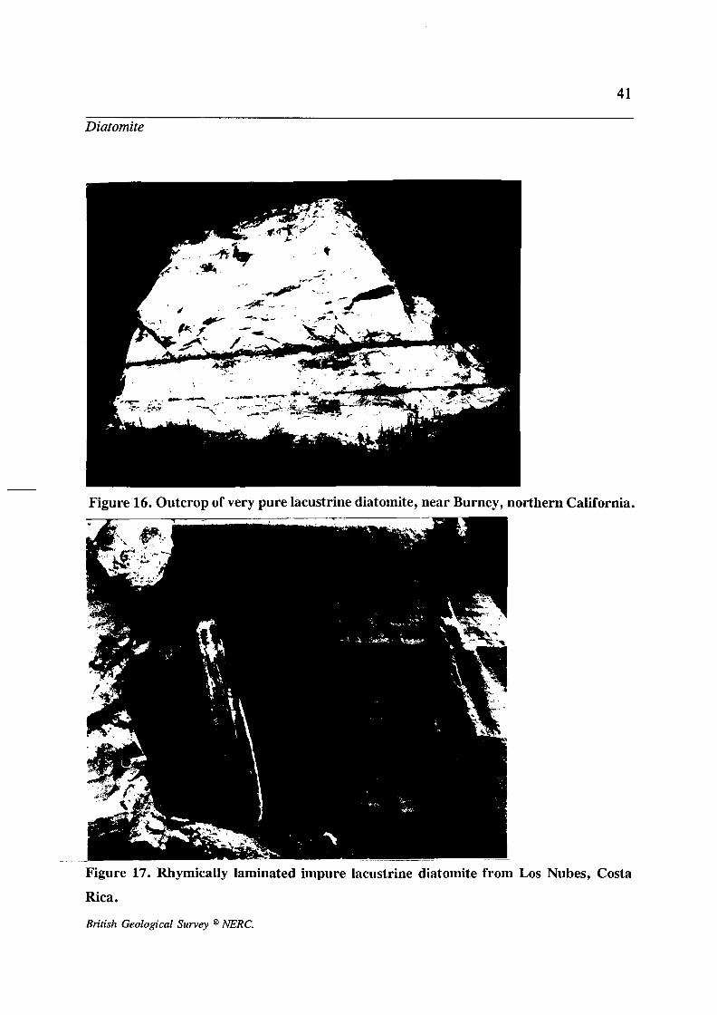
16. Outcrop of very pure lacustrine diatomite, near Burney, northern California.
17. Rhymically laminated impure lacustrine diatomite from Los Nubes, Costa Rica.
18. Graphic lithological log and bulk density of section in the Loma Camastro lacustrine diatomite of Costa Rica; from Mathers and others (1990).

19. The Eijkelkamp extendable auger system with cutting shoes for A, sand and gravel, B, clays, and C, soft and water-logged sediments.
20. Continental distribution, postulated ocean circulation patterns and major phosphorite deposits in the Late Tertiary; after Sheldon (1982).
21. Stratigraphical distribution of sedimentary phosphorites produced in 1978; after Notholt ( 1980).
22. Dark grey peloidal phosphate with interbeds of chalk and chert; A1 Hisa phosphorite, Cretaceous, Central Jordan.
23. Idealised mode of occurrence of elemental sulphur deposits in salt domes; after Gittinger (1975).
24. Section through the Mishraq stratiform sulphur deposit, northern Iraq; after Cortesini (1966).
25. Sulphur-rich crater lake, Poas volcano, Costa Rica.
26. Sublimation sulphur deposits formed around fumaroles at La Solfatara near Naples, Italy.
LIST OF TABLES
1. Geological classification of industrial minerals used in this series of guides, based loosely on the classification employed in Geology of the Nonmetullics by Harben & Bates (1984).
2. Basic mineralogical and chemical data for the principal rock-forming carbonate minerals.
3. Classification of limestones (Dunham, 1962).
4. Classification of limestones (Wright, 1992).
5. Geophysical location of solutional features in carbonates; from Geological Society Engineering Group Working Party (1988).
6. Basic mineralogical and chemical data for iron sulphide minerals.

2
Industrial Minerals E-cploration Guide
Table 1. Geological/genetic classification of industrial mineral
commodities based loosely on Harben & Bates (1984).
Biogenic Sedimentary Rocks - Carbonate Rocks - Diatomite - Phosphate Rock - Sulphur Clastic Sedimentary Rocks - Sand and Gravel - Silica Sands - Clays (Common, kaolins, bentonites) - Mineral Sands Chemical Sedimentary Rocks - Barite - Salt - Sodium salts - Gypsum and Anhydrite - Potassium minerals - Borates - Celestite - Nitrates - Other halides Surfkial Diagenetic Deposits - Vermiculite - Manganese minerals - Bauxite - Iron oxides (Ochres, Umbers) - Zeolites Intrusive Igneous Rocks - Olivine - Chromite - Nepheline Syenite - Granite
Continued overleaf
British Geological Survey NERC.

3
Industrial Minerals Ecploration Guide
Pegmatitic & Hydrothermal Minerals - Feldspar - Mica
- Lithium minerals - Beryllium minerals - Fluorspar Extrusive Igneous Rocks - Basalt - Pumice and Scoria - Perlite - Obsidian Metamorphic Rocks & Minerals - Slate - Asbestos - Talc and Pyrophyllite - Graphite - Sillimanite Group minerals - Corundum and Garnet - Wollastonite - Jadeite
- Quartz crystal
British Geological Survey @ NERC.
4
Carbonate Rocks
CARBONATE ROCKS
Introduction
A wide range of industrial mineral commodities is encompassed by the
term carbonate rocks, the most important being limestone, dolomite,
magnesite and marble. These commodities have a myriad of different
applications utilizing the specific physical or chemical properties of the
carbonate minerals they contain. The principal uses of limestone for
example are as an aggregate, in cement and lime manufacture and as
a filler (for a more complete review see Hankon, 1992). Dolomite
and magnesite are commonly utilized for their refractory properties
and in steel making. Marble is chiefly used as a dimension and
ornamental stone and as a high-quality filler.
Geological occurrence
Geologically, carbonate rocks have diverse origins; they include
sediments, igneous intrusions and the products of metamorphism.
Sedimentary and diagenetic carbonates
The main carbonates are limestone and dolomite which together
comprise over 15 % of the world's sedimentary rocks and range in age
from Precambrian to Recent. By definition limestones contain more
than 50% calcite or aragonite (both are forms of CaCO,). With
substitution of half the calcium by magnesium, dolomite CaMg (CO,),
is produced (Figs 1, 2; Table 2). Complete substitution yields
British Geological Survey @ hERC.
5
Figure 1. Principal carbonate minerals.
Other minerals
Aragonite
Figure 2. Terminology applied to Carbonate Rocks. British Geological Survey @ NERC.
6
Carbonate Rocks
magnesite (MgCO,) another useful industrial mineral commodity.
Carbonates of very high purity are rare and particularly valuable
industrial minerals.
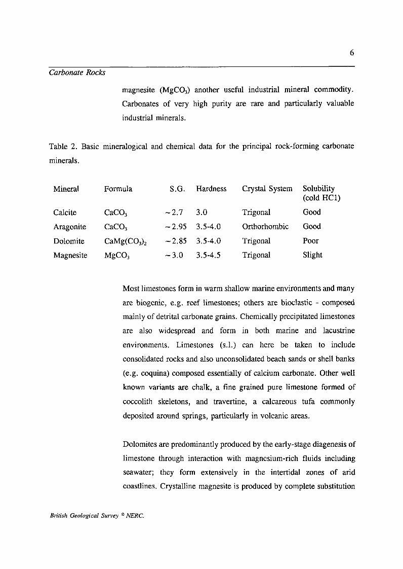
Table 2. Basic mineralogical and chemical data for the principal rock-forming carbonate
minerals.
Mineral Formula S.G. Hardness Crystal System
Calcite CaCO, -2.7 3.0 Trigonal
Aragonite CaCO, -2.95 3.5-4.0 Orthorhombic
Dolomite CaMg(CO,), -2.85 3.5-4.0 Trigonal
Magnesite MgC0, -3.0 3.5-4.5 Trigonal
Solubility (cold HC1)
Good
Good
Poor
Slight
Most limestones form in warm shallow marine environments and many
are biogenic, e.g. reef limestones; others are bioclastic - composed
mainly of detrital carbonate grains. Chemically precipitated limestones
are also widespread and form in both marine and lacustrine
environments. Limestones (s.1.) can here be taken to include
consolidated rocks and also unconsolidated beach sands or shell banks
(e.g. coquina) composed essentially of calcium carbonate. Other well
known variants are chalk, a fine grained pure limestone formed of
coccolith skeletons, and travertine, a calcareous tufa commonly
deposited around springs, particularly in volcanic areas.
Dolomites are predominantly produced by the early-stage diagenesis of
limestone through interaction with magnesium-rich fluids including
seawater; they form extensively in the intertidal zones of arid
coastlines. Crystalline magnesite is produced by complete substitution
British Geological Survey @ NERC.
7
Carbonate Rocks
of calcium by magnesium, often as a result of hydrothermal alteration
of dolomites. Cryptocrystalline magnesite on the other hand occurs as
veins produced by reaction of host olivine-rich ultrabasic/ultramafic
intrusives and serpentinites with carbonate groundwater.
Magnesite, in finely disseminated form, is also found in fine-grained
sediments derived from these parent lithologies
Carbonatites
Carbonatites are intrusive igneous rocks, composed mainly of calcite;
they tend to occur either as individual plugs, or in nested ring
complexes associated with alkaline and ultrabasic lithologies.
Carbonatites are volcanic "roots" and tend to occur in belts located
along major structural lineaments in the basement terrain of stable
cratonic blocks. As carbonates they tend to be relatively impure but
are extracted commercially in areas where they represent the only
available source of carbonate. They are chiefly used for lime and
cement manufacture. Some carbonatites, and in particular the residual
soils developed on them, contain economic concentrations of
fluorapatite (cf Phosphate Rock, this volume) and rare-earth bearing
minerals such as pyrochlore.
Metamorphic carbonates
Isochemical metamorphism of a relatively pure carbonates produces
marble. In regional metamorphic terrains marbles tend to occur as beds
which usually trace out the considerable structural complexity and
dislocation characteristic of such environments. Contact metamorphic
British Geological Survey @ NERC.
8
Carbonate Rocks
marbles are more irregular in form and may grade with increasing
distance from the intrusive contact into unaltered limestone. Near contacts with acidic plutons, occurrences of wollastonite and other less
common calcium-rich skarn minerals are sometimes closely associated
with marble. The transformation to marble produces a tough, compact,
massive lithology with few fractures. When pure white or with
attractive hues (produced by minor impurities or textural variations),
marble is a valuable commodity for use as a dimension or ornamental
stone.
Exploration and field evaluation
Sedimentary, diagenetic and metamorphic carbonates
Carbonate rocks are by no means rare, and whilst not ubiquitous they
do occur in one form or another in most areas. In most regions the
outline geology is sufficiently well-known, and carbonate deposits
sufficiently common, for their occurrence and broad distribution to be
known. Therefore primary exploration for most carbonates is not
needed; usually what is required is a more detailed evaluation of a
poorly-known occurrence to determine its characteristics, namely type,
volume, grade, variability and suitability for a particular end-use.
An initial appreciation of the lateral extent of any carbonate deposit
would normally be obtained by a combination of remote sensing and
reconnaissance field traverses.
British Geological Survey NERC.

9
Carbonate Rocks
Remote sensing
Modern remote sensing techniques such as satellite images derived
from the Thematic Mapper (TM) are beginning to enable some
lithological discrimination under favourable conditions. The older
LANDSAT images however are of limited use in this regard.
Carbonate minerals cannot be distinguished one from another, since
most have their principal absorptions around 2.34pm. This wavelength
lies on the edge of TM band 7. Studies of sedimentary sequences on
the Sinai Peninsula, Egypt (Marsh & O'Connor, 1992), have met with
some success in discriminating carbonates from adjacent clays and
sulphate-bearing rocks. This was achieved because the carbonate
lithologies encountered tended to develop a weathered surface which
produced a relatively weak Band 7 response, contrasting with a much
stronger signal for the other lithologies.
Aerial photographs are of considerable importance in regional
assessments. In general carbonates are relatively tough rocks and,
especially when thickly or massively bedded, they tend to resist
mechanical erosion. Outcrops of relatively pure carbonates tend to
produce a light tone although impure variants may be considerably
darker.
In wet climates, or areas that have experienced wet conditions in the
geologically recent past, limestones and marbles have a distinct
morphological expression. This develops as a result of their relatively
high solubility in rainwater (the magnesium-bearing carbonates are
much less soluble). Internal (subsurface) drainage systems readily
British Geological Survey @ hERC.

10
Carbonate Rocks
develop; these are marked by features such as sinkholes, solutional
collapse structures and other karstic landforms, and springlines at the
base (Fig. 3). Surface outcrops usually show preferrential solution
along high angle fractures and faults; sinkholes are commonly located
at their intersections.
By contrast, in arid climates limestones and marbles tend to form
resistant beds and may be difficult to distinguish from sandstones using
aerial photographs. Limestones do tend to display more jagged forms
with prominent screes, and usually have longer dip-slopes and
smoother bedding planes.
Pure limestones and marbles being almost entirely soluble tend to
develop little soil cover and vegetation; impure limestones and
carbonatites can produce thick residual soils such as "terra rosa", and
are commonly thickly vegetated. In addition these insoluble residual
soils often contain economic concentrations of chemically resistant
minerals such as barite and, in the case of carbonatites, apatite,
magnetite and rare earth-bearing minerals.
In humid tropical climates and volcanically active areas travertine
deposits are commonly developed around springs.
Provisional interpretations based on remotely sensed data are usually
followed up by reconnaissance field traverses to confirm lithological
identity and detail.
British Geological Survey @ NERC.

11
Sandstone hills Limestone platform (with surface drainage) Clay plain
&
Limestone gorge formed by the collapse ofthe roof of an underground cave
River re-appea rs at the foot of the Limestone cliff ,Dry va I ley
River disappears down swallow hole
bnderground caverns
Figure 3. Elements of karst geomorphology.
British Geological Survey @ NERC.

12
Carbonate Rocks
Field geology
At a more detailed level of investigation, and in areas where remote
sensing data are not available or helpful, geological surveying is the
prime tool of investigation. Detailed topographic maps (published or
if necessary surveyed specially) and/or aerial photographs are required
for locating and recording observations.
Mapping out the distribution of a carbonate bed involves the careful
and systematic recording of its geomorphological expression, available
sections and distribution of diagnostic soil types. Despite being
soluble in acidic water, many carbonates form prominent scarp and dip
features due to their resistance to mechanical erosion. This is
particularly marked in gently dipping stata where the carbonate is
interbedded with "soft" argillaceous sequences. In flat-lying strata
extensive karstic plateaux develop controlled by major bedding planes.
Spring lines are particularly useful in mapping out the base of
limestones where they rest on impermeable beds; conversely swallow
holes are likely to occur close to the top of a unit. (Fig. 3).
Soils developed on carbonates are also particularly diagnostic. Soluble
(calcium) carbonates tend to produce soils composed of their insoluble
residues; many have a characteristic orange-red colouration due to iron
(e.g. rezina soils). Other common constituents include barite, pyrite,
base metal sulphide minerals, clay minerals and silica; in carbonatites
residual soils are usually dominated by fluorapatite and magnetite.
Relatively impure carbonates tend to form thicker residual soils which
are able to support more extensive vegetation. Also diagnostic of
carbonate outcrops, and sometimes a useful additional clue to their
British Geological Survey @ NERC.

13
Carbonate Rocks
presence, are the very distinct floral assemblages of calcium-loving
species that develop.
Exposures of stratiform sedimentary and metasedimentary carbonates
should be recorded carefully by not only gathering structural
information (strike, dip etc.), but also by the preparation of a carefully
annotated graphic log showing the thickness and lithological character
of the beds. These logs should ideally be constructed to scale on graph
paper and incorporate detailed observations such as colour, lithology , fauna, degree of fracturing, mineralization and alteration. These
graphic logs are invaluable for lithological correlation of sequences and
provide key information on the internal variability of the deposit and
thus its suitability for many end-uses.
Much useful information can be derived from the examination of
surface exposures (Fig. 4), although in isolation this style of
assessment suffers from several disadvantages:
a) Exposures rarely display thick or complete stratigraphic sequences
thus posing uncertainties for lithostratigraphical correlation.
b) Bias easily creeps into the recording and sampling of exposures;
care must be taken to be representative not selective.
c) Some sections tend to occur as vertical rockfaces
making access for examination and sampling difficult.
d) Care should be taken to avoid sampling weathered material; in
humid climates carbonate rocks tend to be leached producing a
British Geological Survey @ NERC.

14
Carbonate Rocks
~
Figure 4. Carboniferous Limestone, Gordale Scar, northern England.
Figure 5. Field use of point-load testing equipment.
British Geological Survey @ NERC.

15
Carbonate Rocks
relatively impure carbonate layer whereas in arid climates the surficial
crust may be enriched in carbonate.
By being aware of these factors considerable amounts of useful data
can be obtained from the logging and sampling of outcrops. If funds
permit the preferred method of assessment of a carbonate resource
involves drilling. In this case information gathered from exposures
should be used as a supplement. It is recognized however that in many
developing countries either budgets for drilling may be unobtainable
or there may be operational difficulties which make drilling
impractical.
Construction of graphic logs of sections (or cores) involves careful
examination of hand specimens. Using the naked eye and/or a hand
lens the principal textures and constituents of a specimen can be
determined. Primary carbonates are usually classified in hand specimen
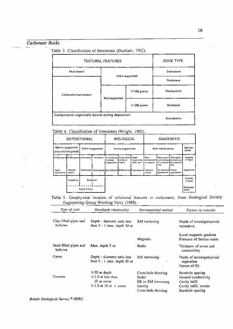
with reference to the system of Dunham (1962) shown in Table 3 or
using subsequent schemes developed from it (e.g. Wright, 1992;
shown in Table 4). For more detailed description and identification of
textures, cements and carbonate grains, the reader should consult
standard reference texts such as Bathurst (1975).
The development of secondary dolomite usually results in an
overprinting or obliteration of the primary texture by the characteristic
pale brown sacharroidal appearance of the closely interlocking
dolomite crystals. Marbles are usually coarse equigranular crystalline
rocks in which traces of fracturing and bedding have largely
disappeared due to annealing and recrystallization of the carbonate
minerals.
British Geological Survey @ NERC.
16
TEXTURAL FEATURES
Mud absent
Grain-supported
>10% grains Carbonate mud present
Mud supported
>10% grains
Carbonate Rocks -
Table 3. Classification of limestones (Dunham, 1962).
ROCK TYPE
Grainstone
Packstone
Wackestone
Mudstone
DEPOSITIONAL BI 0 LOGICAL DIAGENETIC
Obliter- ative Matrlx-supported Graln-supported In situ organisms Non- obliterative
(clay and silt grade)
<lO%grains>lO%grains withmatrix nomatrix Encrusting Organisms Rtgld Main Manygram Mostgrain Crystals binding acted to organisms component contacts as contacts are >loym organisms baffle dominant iscement mtcrosrylol mcrosrylol-
ites ites
Calci- Wacke. Packstone Grainstone Boundstone Bafflestone Framestone Cement- Condensed Fined Sparstone mudstone stone stone grainstone gramstone
Clay-filled pipes and Depth : diameter ratio less EM traversing Depth of investigation/coil hollows then 2 : 1 max. depth 30 m separation
Magnetic
Sand-filled pipes and Max. depth 5 m Radar hollows
Caves
Caverns
Depth : diameter ratio less than 2 : 1 max. depth 30 m
EM traversing
>30 m depth Cross-hole shooting > 1 .O at less than
10 m cover > 1.0 at 10 m + cover
Radar ER or E M traversing Gravity Cross-hole shooting
Local magnetic gradient Presence of ferrous waste
Thickness of cover and conductivity
Depth of investigatiodcoil separation
Nature of fill
Borehole spacing Ground conductivity Cavity infill Cavity infill, terrain Borehole spacing
British Geological Survey @ NERC.
17
Carbonate Rocks
Several simple chemical tests can be applied in the field to help
distinguish the individual carbonate mineral species. One method is to
etch a relatively flat surface of the rock with a weak acid solution (say
1/10 Normal HC1); this has the effect of preferentially dissolving
calcium carbonate minerals and leaving dolomite, magnesite and other
less soluble and insoluble impurities standing proud. The etching will
also enhance the texture and fabric of the rock.
A more sophisticated approach involves the use of staining techniques
which enable more precise distinctions to be made between most of the
common carbonate minerals. One of the most popular stains for
carbonates - potassium ferricyanide - needs to be handled with caution
and skin contact avoided. The other commonly used reagent, Alizarin
Red S is not regarded as hazardous. Always follow the manufacturers
guidelines when handling chemicals!
Staining solutions can be prepared in dropper bottles and used in the
field directly on rock surfaces. The most useful stains have been
described in the corresponding ODA/BGS Industrial Mineral
Laboratory Manual on Limestone (Harrison, 1992); these are
summarized below:
Alizarin Red S in 30% NaOH. Stains Mg-calcite and dolomite
purple.
Alizarin Red S in 1.5% HC1. Stains calcite and aragonite red;
ferroan dolomite and ferroan calcite purple.
British Geological Survey @ NERC.
18
Carbonate Rocks
Potassium ferricyanide in dilute HC1. Stains iron-bearing carbonates
dark blue (dolomite usually contains some iron whereas calcite does
not)
Potassium ferricyanide and Alizarin Red S in 1.5% HC1. Stains
calcite pink or red and ferroan calcite purple. Dolomite is unaffected
but ferroan dolomite turns turquoise. This technique allows all
common phases to be identified in one stage (Dickson, 1965; 1966).
All staining solutions should be freshly mixed and not stored for more
than 24 hours before useage. Other useful summaries of carbonate
staining techniques are given in Leeder (1982) and Miller (1988).
Field determination of Specific Gravity (SG) using a simple balance
can be useful in identifying magnesite (SG = -3.0) from dolomites
(SG = 2.85) according to Wicken & Duncan (1983). Such
determinations however are better performed in field laboratories.
Simple determinations of the strength of samples or core can also be
obtained in the field by using portable point-load testing equipment
(Franklin and others, 1971; Broch & Franklin, 1972; Brook & Misra,
1970), as shown in Fig. 5. Alternatively, the Schmidt hammer test has
been used (Deere & Miller, 1966; Harrison and others, 1982).
However experience with such techniques has revealed problems of
reproducibility in many limestone lithologies (Harrison, 1983) and
these technique are probably best reserved for laboratory use on large
sawn samples of carbonates with few bedding or fracture surface (e.g.
marbles). A further drawback to the use of these tests is that they
measure the strength of the rock rather than the strength in its final
British Geological Survey @ NERC.

19
Carbonate Rocks
form as a crushed rock aggregate.
Geophysics
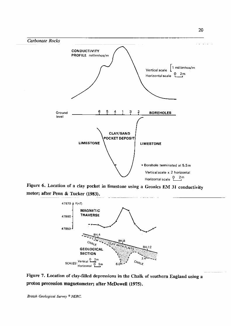
Due to the tendency of carbonates to dissolve in weak acidic solutions
and develop underground drainage, many carbonates and in particular
limestones are cavernous and contain surficial solutional depressions
which can become infilled with soil, clay and windblown sediments.
Clearly the location of voids and clay-filled pockets within the deposit
are important in terms of carbonate purity, available reserves,
extraction plans, ground stability and hydrogeology . Although the
presence of some clay-filled hollows may be deduced from soil type
or geomorphology , geophysical techniques represent the best means of
assessing the presence of caverns and infilled solution hollows. Table
5 shows the techniques most suited to this type of problem.
Examples of the detection of shallow clay-rich pockets on limestone
outcrops are given in Figures 6 and 7 . These demonstrate the
effectiveness in this context of a portable non-contacting ground
conductivity meter and magnetic profiling using a proton precession
magnetometer.
However it cannot be stressed too strongly that despite the capabilities
of these techniques, some ground truth (i.e boreholes or augerholes)
must be established in order to properly interpret (calibrate) the
geophysical information.
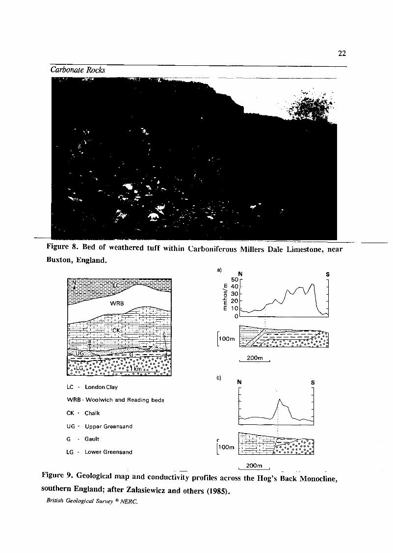
Where carbonates are interbedded with clay-rich beds of at least l m
thick (Fig. 8) these can often be located at outcrop by traversing across
British Geological Survey @ NERC.
20
CONDUCTIVITY PROFILE rnillirnhos/rn
0 2rn Vertical scale
Horizontal scale U
Ground f ? 1 BOREHOLES level
f LI M ESTO N E LI M ESTO N E
+ Borehole terminated at 5.5rn
Vertical scale x 2 horizontal
Horizontal scale U 0 2rn
Figure 6. Location of a clay pocket in limestone using a Geonics EM 31 conductivity
meter; after Penn & Tucker (1983). ~- ~~ - - ~ ~~ ~~ ~
47870 F(nT)
MAGN ETlC 47860 TRAVERSE
f - n-a ! La/# 47850
GEOLOGICAL ' SECTION
SCALES: Horizontal -
Figure 7. Location of clay-filled depressions in the Chalk of southern England using a
proton precession magnetometer; after McDowell (1975).
British Geological Survey @ NERC.

21
Carbonate Rocks
the strike using portable ground conductivity meters. These meters
have also been used to refine the outcrop pattern of carbonates in
poorly exposed terrain (e.g. Zalasiewicz, Mathers & Cornwell, 1985:
Fig. 9 herein). Down-the-hole geophysical logs of carbonate sequences
are also useful in pinpointing clay-rich layers and units and in
determining the overall stratigraphy and unit boundaries. In this
situation the most useful information usually comes from the natural
gamma ray logs produced by equipment such as the Mount Sopris
logger shown in Fig. 10. On the gamma logs most argillaceous strata
give strong positive anomalies due to a relatively high content of
radioactive elements (commonly 40K).
The very low frequency electromagnetic method (VLF-EM) technique
has been applied in the basement terrain of Nigeria where mapping of a steeply-dipping bed of dolomitic marble (about 60m wide) within
quartzites was refined (Aina & Emofurieta, 1991). The equipment used
in this study was the Geonics EM 16 instrument.
The rippability (ease of excavation) of carbonates can be gauged by
assessing seismic refraction P-wave velocities. In simple terms, beds
with P-wave velocities of less than 1200 m/sec can be considered
relatively easy to excavate. With increasing seismic velocity (indicating
for example less fracturing, stratification or weathering) excavation
becomes progressively more difficult; rocks with velocities over about
2000 m/sec generally require blasting (Geological Society Engineering
Group Working Party, 1988; Weaver, 1975.).
British Geological Survey @ NERC.
22
Carbonate Rocks
Figure 8. Bed of weathered tuff within
Buxton, England.
LC - LondonClay
WRB - Woolwich and Reading beds
CK - Chalk
UG - Upper Greensand
G - Gault
LG - Lower Greensand
Carboniferous Millers Dale Limestone, nea
a’ N 50 r
S 1
, 200m ,
N S
200m , Figure 9. Geological map and conductivity profiles across the Hog’s Back Monocline,
southern England; after Zalasiewicz and others (1985). British Geological Survey @ NERC.

23
Firmre 11. The Tororo Rock carbonatite ~ l u e . southeastern Uganda. British Geological Survey @ NERC.
24
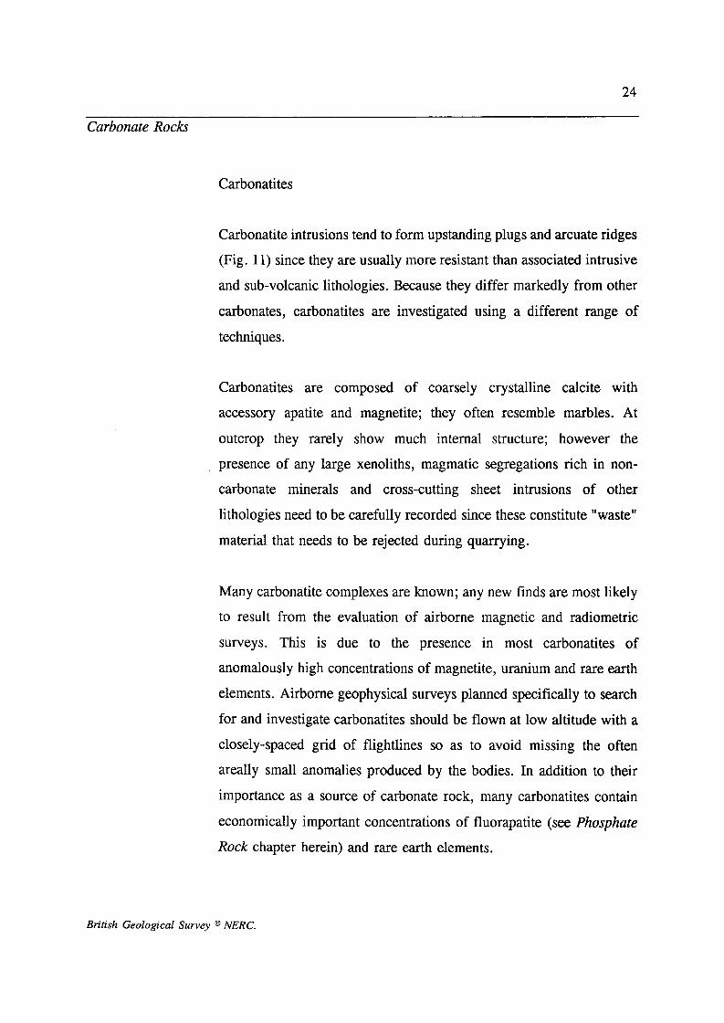
Carbonate Rocks
Carbonatites
Carbonatite intrusions tend to form upstanding plugs and arcuate ridges
(Fig. 11) since they are usually more resistant than associated intrusive
and sub-volcanic lithologies. Because they differ markedly from other
carbonates, carbonatites are investigated using a different range of techniques.
Carbonatites are composed of coarsely crystalline calcite with
accessory apatite and magnetite; they often resemble marbles. At
outcrop they rarely show much internal structure; however the
presence of any large xenoliths, magmatic segregations rich in non-
carbonate minerals and cross-cutting sheet intrusions of other
lithologies need to be carefully recorded since these constitute "waste"
material that needs to be rejected during quarrying.
Many carbonatite complexes are known; any new finds are most likely
to result from the evaluation of airborne magnetic and radiometric
surveys. This is due to the presence in most carbonatites of
anomalously high concentrations of magnetite, uranium and rare earth
elements. Airborne geophysical surveys planned specifically to search
for and investigate carbonatites should be flown at low altitude with a
closely-spaced grid of flightlines so as to avoid missing the often
areally small anomalies produced by the bodies. In addition to their
importance as a source of carbonate rock, many carbonatites contain
economically important concentrations of fluorapatite (see Phosphate
Rock chapter herein) and rare earth elements.
British Geological Survey @ NERC.
Carbonate Rocks
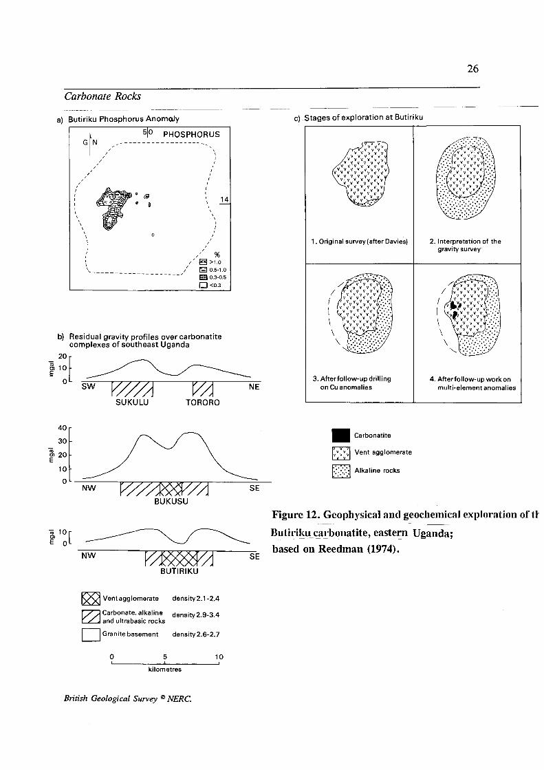
Residual soil geochemistry has proved invaluable in the delineation of
carbonatite bodies within the previously poorly-known Butiriku
Complex of south-eastem Uganda (Reedman, 1974). The detailed
structure of this body had evaded previous studies due to an extensive,
thick blanket of residual soil. An area of 38 km2 of residual soils was
sampled on a grid pattern leading to the detection of multi-element (P,
Nb, REE, Zn, PB, MO and Be) anomalies which indicated the
presence of buried masses of carbonatite. (Fig. 12a,c). When
combined with geophysical studies, pitting and drilling, the geology of
the whole complex was revealed.
Ground gravimetric surveys are also useful in delineating the structure
of carbonatite complexes. Again the study of Reedman (1974)
illustrates how residual gravity profiles of five carbonatites from south-
eastern Uganda give rise to strong positive anomalies associated with
masses of carbonatite (density 2.9 - 3.4) which were discriminated
from lighter surrounding granitic basement (density 2.6- 2.7) and allied
agglomerates (density 2.1-2.4) (Fig, 12b,c).
Ground surveys using scintillometers and magnetometers are also
useful in delineating the structure of carbonatite complexes and
separating their constituent intrusive lithologies. Seismic techniques
should also be effective in defining the interface between
unconsolidated residual soil cover and the bedrock.
British Geological Survey @ NERC.
26
40
30
20
1 0
-
O L
a) Butiriku Phosphorus Anomdy
- - -
-
c) Stages of exploration a t Butiriku
0
b) Residual gravity profiles over carbonatite complexes of southeast Uganda
NE O L
sw V//' . - -
SU KU LU TORORO
NW SE
v v v v v ~ "
v ~ v v v v v v v v v
v ~ v v v ~ v v v v v v v v v
~ v v v v v v v v v v v
v v v v v
v v v v v v
v v v v v v v v v v v v v v v
v v v v v v v
v v v v v c) v v v v v v ...'
1. Original survey(after Davies)
3 . Afterfollow-up drilling on Cu anomalies
Carbonatite
Vent agglomerate
Alkaline rocks . .
2. Interpretation of the gravitysurvey
4. Afterfollow-up workon multi-element anomalies
BUKUSU
Figure 12. Geopl~ysical and geochemicd exploration of l h ~ ~ ~-
, 1 0 [ 7 E O Rut iri _ - ~ ~ fcu carb 0 1 la t ite, eastern ~ Uganda; based on Reedman (1974).
NW SE
BUT1 R I KU
Ventagglomerate density2.1-2.4
Carbonate, alkaline density2.9-3.4 and ultrabasic rocks 0 Granite basement density2.6-2.7
0 5 10
kilometres
British Geological Survey @ NERC.
27
Carbonate Rocks
Drilling and sampling
Once the surface distribution of a carbonate is relatively well known
detailed assessment can commence to evaluate the grades and tonnages
available. Individual studies vary from regional resource assessments
of carbonates for all uses, to site-specific reserve calculation with a
view to quarrying for a particular end-use.
The type of drilling programme will depend mainly on: the level of
detail required (i.e. resources or reserves), the exploration budget and
the volume of core material needed for testing. Rotary diamond
drilling is normally employed.
Except in the most general of assessments drilling is usually carried
out with regularly spaced boreholes; in more detailed work these are
usually drilled on a grid pattern. In regional assessments of the
Carboniferous Limestone resources of the Peak District in central
England, boreholes could be correlated satisfactorily over distances up
to 6 km apart (Cox, Bridge & Hull, 1977). Whereas at the other end
of the scale quarry operators commonly employ drilling grids with 30
m centres to detect minor variations in properties, for example where
Mg content is of concern in cement manufacture.
The choice of core diameter is governed by cost, availability, or the
amount of material required for testing. Core diameters between about
40 mm and 60 mm are generally used for general assessment purposes.
Drilling is usually rotary diamond drilling preferably with wireline
equipment and using either air-, watedfoam- or water-flushing, the
latter being more effective in cherty lithologies. Smaller portable drill
British Geological Survey NERC.

28
Carbonate Rocks
rigs (e.g. Minuteman or Winkie) can be used in inaccessible locations
and in an ancillary capacity to obtain narrow diameter (up to 22 mm)
core from the first few metres of ground where coring with larger
capacity drilling rigs is usually difficult (Cox, Bridge & Hull, 1977).
Where large volumes of core material are needed for physical and
mechanical testing (for example for roadstones) much larger diameter
boreholes are drilled with diameters ranging up to about 300 mm (Carr
& Rooney, 1983).
It is desirable to log uncased boreholes with a portable gamma ray
logger to serve as a useful indicator of clay content and guide for
correlation. Core should be logged provisionally on-site, and include
an assessment of the fracture index (number of discontinuities divided
by unit thickness).
References
Aina, A. & Emofurieta, W.O. 1991. The use of very low frequency
electromagnetic method for non-conductive resource evaluation and
geological mapping. Journal of African Earth Sciences, 12, 609-616.
Bathurst, R.G.C. 1975. Carbonate Sediments and their Diagenesis.
2nd Edition. Developments in Sedimentology 12. Elsevier,
Amsterdam.
Broch, E. & Franklin, J.A. 1972. The point load strength test.
Institute Journal of Rock Mechanics and Mineral Science 9, 669-697.
British Geological Survey @ NERC.
29
Carbonate Rocks
Brook, N. & Misra, B. 1970. A critical analysis of the stamp mill
method of determining Protodyakonov Rock Strength and the
development of a method of determining a Rock Impact Hardness
Number. Proceedings of the 12th Symposium of Rock Mechanics,
Missouri, 157-165.
Can, D.D. & Rooney, L.F. 1983. Limestone and Dolomite. In Industrial Minerals and Rocks, 5th Edition, 2 Vols. Lefond, S.J. (Ed)
833-868. American Institute of Mining, Metallurgical and Petroleum
Engineers, New York.
Cox, F.C., Bridge, D. McC. & Hull, J.H. 1977. Procedure for the
assessment of limestone resources. Mineral Assessment Report No. 30,
Institute of Geological Sciences, London, 14p.
Deere, D.U. & Miller, R.P. 1966. Engineering classification and
index properties for intact rock. Technical Report Am-ZX-65-116,
Air Force Weapons Ltd. Kirkland Air Force Base, New Mexico.
Dickson, J.A.D. 1965. A modified staining technique for carbonates
in thin section. Nature, 205, 587.
Dickson, J.A.D. 1966. Carbonate identification and genesis as
revealed by staining. Journal of Sedimentary Petrology, 36, 491-505.
Dunham, R. J. 1962. Classification of carbonate rocks according to
their depositional texture. In Classijkation of Carbonate Rocks, Vol
1. Ham, W.E. (Ed) 108-121. American Association of Petroleum
Geologists, Tulsa.
British Geological Survey @ NERC.
30
Carbonate Rocks
Franklin, J.A., Broch, E. & Wilton, G. 1971. Logging the mechanical
character of rock. Transactions of the Institute of Mining and
Metallurgy, 80, A, 1-9.
Geological Society Engineering Group Working Party, 1988.
Engineering Geophysics. Quarterly Journal of Engineering Geology,
21, 207-271.
Harrison, D.J. 1983. Geological problems associtaed with the
assessment of resources of limestone and sandstone. In Prospecting
and Evaluation of Non-metallic Rocks and Minerals. Institution of
Geologists, London, 127-137.
Harrison, D. J. 1992. Limestone. Industrial Minerals Laboratory
Manual, British Geological Survey Technical Report WG/92/29,45pp.
Harrison, D.J., Wild, J.B.L. & Adlam, K. McL. 1982. South Wales
Hard Rock Feasibility Study - A Preliminary Report Mineral
Assessment Internal Report Series No. 82/2. Institute of Geological
Sciences.
M e r , M.R. 1982. Sedimentology, Allen & Unwin. 344pp.
McDowell, P. W. 1975. Detection of clay filled sink-holes in the chalk
by geophysical methods. Quarterly Journal of Engineering Geology,
8, 303-310.
Marsh, S.H. & O’Connor, E.A. 1992. Exploration for building
materials and industrial minerals in arid regions using satellite remote
British Geological Survey @ NERC.
31
Carbonate Rocks
sensing: progress report for 199 1/92. British Geological Survey,
Technical Report WC/92/15. 17p.
Miller, J. 1988. Microscopical techniques: Slices, slides, stains and
peels. In Techniques in Sedimentology, Tucker, M. (Ed) Blackwell,
Oxford. 86-107.
Penn, S. & Tucker, D. 1983. The application of geophysics to quarry
overburden problems. In Prospecting and Evaluation of Non-metallic
Rocks and Minerals. Institution of Geologists, London, 149-156.
Reedman, J.H. 1974. Residual soil geochemistry in the discovery and
evaluation of the Butiriku carbonatite, southeast Uganda. Transactions
of the Institute of Mining and Metallurgy, London. Section B, 83, B1-
12.
Weaver, J.M. 1975. Geological factors significant in the assessment
of rippability. Civil Engineer of South Africa, 17, 313-316.
Wicken, O.M. & Duncan L.R. 1983. Magnesite and related minerals.
In Industrial Minerals and Rocks, 5th Edition, 2 Vols. Lefond, S.J.
(Ed) 881 - 896. American Institute of Mining, Metallurgical and
Petroleum Engineers, New York.
Wright, V.P. 1992. A revised classification of limestones. Sedimentary
Geology, 76, 177-185.
Zalasiewicz, J.A., Mathers, S.J. & Cornwell, J.D. 1985. The
application of ground conductivity measurements to geological
British Geological Survey @ NERC.

32
Carbonate Rocks
mapping. Quarterly Journal of Engineering Geology 18, 139- 148.
British Geological Survey @ NERC.

33
Diatornite
DIATOMITE
Introduction
Diatomite is a soft , pale-coloured sedimentary rock composed of the
skeletal remains of diatoms - minute unicellular aquatic algae
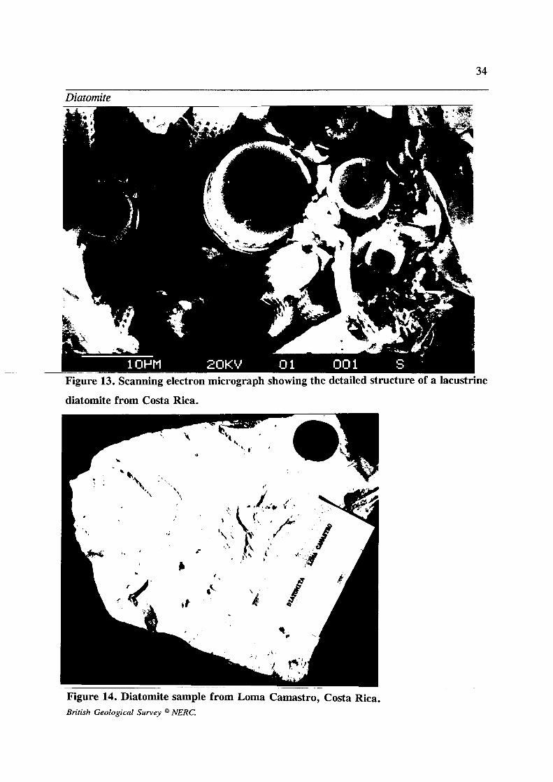
commonly 20 - 200 pm in diameter (Figs 13, 14). Diatoms precipitate
a perforate cell-wall of opaline silica to protect their soft organic
interior. After death the organic material decays leaving the siliceous
skeletons to sink to the bottom of the watermass. Here they accumulate
in vast numbers to form diatomaceous oozes which are subsequently
compacted to form diatomite. Processed diatomite powders have a
unique physical structure and are moderately refractory and chemically
inert. They are used in a wide variety of industrial applications as
filter-aids, fillers and a mild abrasives.
Geological occurrence
Diatoms live in a wide variety of environments from the open ocean
to nearshore; and in freshwater rivers, lakes and marshes. Based on
their diagnostic floral assemblages and sedimentary associations,
ancient diatomites are readily classified into marine and freshwater
deposits.
Many freshwater and marine deposits are closely associated with
volcanism (Fig. 15) which provides a ready supply of dissolved silica
which the diatoms need to construct their skeletons (Taliaferro, 1933;
Mulryan, 1942; Williamson, 1966; Kadey, 1983). A rapid expansion
in diatom population following the supply of pyroclastic material from
British Geological Survey @ NERC.
34
Diatomite
Figure 13. Scanning electron micrograph showing the detailed structure of a lacustrine
diatomite from Costa Rica.
Figure 14. Diatomite sample from Loma Camastro, Costa Rica. British Geological Survey @ NERC.

35
Diatornite __ _ _
British Geological Survey @ NERC.
36
Diatomite
an eruption has been recorded in the modern environment (e.g.
Kurenkov, 1966). Similar responses have been recorded in the
stratigraphic record (e.g. Abella, 1988). Under favourable
environmental conditions diatomite ooze can accumulate very rapidly,
perhaps at rates around 1 mm per year (Soper & Obson, 1922; Gams,
1927).
Marine diatomites are commonly characterized by circular (centric),
immobile planktonic forms. Diatomites may be grade into, or be
interbedded with, a wide variety of sedimentary lithologies; the
commonest are mudrocks, carbonates and waterlain pyroclastics.
The most famous deposits are those of the Neogene Monterey and
Sisquoc formations of southern California which are worked
extensively in the Lompoc area (Dibblee, 1950; Woodring &
Bramlette, 1950). Here shallow marine diatomite beds attain an
aggregate thickness of several hundred metres and are associated with
arkoses, rhyolitic tuffs, black and phosphatic mudstones and basaltic
lavas. Individual beds 1 - 10 m thick are mined.
Freshwater fluvial, lacustrine and paludal diatomaceous deposits are
commonly rich in elliptical (pennate) , mobile diatoms, which usually
occur interbedded with waterlain pyroclastics, fine sands, silts, clays
and peat. Economic diatomites of this type are sometimes closely
associated with bentonite, zeolites and pumice. Diatomite-bearing
sequences can be several hundreds of metres thick; however individual
diatomite beds are commonly less than 2 m thick and are finely
laminated, reflecting seasonal or episodic sediment supply.
British Geological Survey @ NERC.
37
Diatomite
Examples of freshwater diatomites associated with volcanism include
the Neogene-Quaternary examples of the western United States
(Williamson, 1966) and Costa Rica (Mathers, 1989). Recent lacustrine
diatomites have been dredged from the floor of Lake Myvatn in
Iceland. The impure diatomaceous deposits at Kentmere, England
(Mitchell, 1934) represent Post-Glacial - Recent deposits that
accumulated in a glaciated valley blocked by a terminal morraine. The
close association with glaciated terrain probably reflects an abundant
supply of silica derived from finely ground silica in glacial deposits
(Conger, 1939).
As relatively simple forms of life diatoms probably have a long
geological history; fossil evidence seems to indicate that they
flourished markedly in the Cretaceous and have been abundant in
Tertiary and Quaternary times. However, older diatom-rich deposits
may be difficult to recognize in the stratigraphic record due to their
diagenetic conversion to chert. All commercially important deposits are
late Tertiary or Quaternary in age.
Diatomites are of variable purity, although the most commonly used
commercial grades contain at least 85% SiO, and are used in the
manufacture of fillers and filter-aids. The most common impurities are
detrital sand and silt, clay, volcanic ash, carbonate and organic
material. Impure clayey diatomite containing about 75% SiO, is used
to make lightweight refractory bricks; such deposits are referred to in
the industry as "moler".
British Geological Survey @ NERC.

38
Diatomite
Exploration and field evaluation
Any exploration for diatomite must be based on an understanding of the geological environments in which it can form, and the age of strata
which can be expected to contain economic deposits (see above).
To be useful commercially, diatomite deposits must be only moderately
compacted and free from the effects of diagenesis, chemical alteration
or metamorphism. Therefore economic deposits are only found in strata of late Tertiary or Quaternary age. Conger (1942) suggests that
uplift and exposure under good drainage conditions are important
factors for the removal of organic material and formation of pure
deposits.
Literature searches and examination of regional geological maps will
help pin-point potential areas, but preference must always be given to
locations closest to the perceived market for the commodity or to
coastal port facilities.
Potentially economic deposits are most likely to be found in shallow
marine and lacustrine sediments which are closely associated with
penecontemporaneous volcanism. Other sites of potential interest
include Quaternary - Recent lacustrine deposits in glaciated terrains
and bog deposits. Recent deposits commonly lie beneath present-day
valley floors and are invariably beneath the watertable; these "wet"
deposits require a distinct investigative approach which is discussed
separately at the end of this section.
An example of a regional appraisal of diatomite occurrence and
British Geological Survey @ NERC.
39
Diatomite
potential of the western United States is given by Williamson (1966,
figs 1 - 3). Most commercial deposits comprise uplifted and eroded
marine and freshwater sediments. Reconnaissance starts with the
examination of available and accessible sections. Most deposits are
first located by "shows" in stream, road sections or as "float" in soils.
Because of its often characteristic white colour and light weight, the
location of many diatomites has been known for centuries by the local
communities. In Costa Rica, for example, several rivers that flow
accross diatomite deposits are called Rio "Tizatl" - the old pre-
Columbian indigenous word for chalk - which it closely resembles
(Mathers, 1989). The name thus serves as a clue to the presence of
diatomite. Air photographs are likely to be useful for delineating areas
of interest and locating sections at the reconnaissance stage of
exploration especially in poorly known terrain where adequate
topographic base maps are not available. A further possible approach
is mentioned by Carter (1971), referring to developmental work then
being carried out by G.W. Greene of the USGS. Greene had
reportedly found that diatomite, because of its distinct thermal
characteristics, could be distinguished using airborne narrow pass-band
thermal infrared imagery (3 - 4 and 4.5 - 5.5 pm). The present author
has tried unsuccessfully to trace subsequent details of this work.
Once it is confirmed that an area contains beds of potentially-economic
diatomite, more detailed exploration can be planned. Detailed
geological surveying of the area, perhaps at 1:25 000 or larger scale,
coupled with an air photograph interpretation, are essential to trace out
the distribution of packets of strata containing diatomite.
Logging of available sections should include the bed by bed recording
British Geological Survey @ hERC.

40
Diatomite
and sampling of the strata, involving the production of an annotated
graphic lithological log together with measurements of the dip, faulting
etc. In the rare event of relatively homogenous, massive beds, channel
samples representing a maximum of 1.5 m of strata are recommended
(Kadey, 1983), but most deposits are more thinly stratified and can be
sampled on a bed-by-bed basis.
Particular attention should be paid to recording the wet and dry colour,
grit content, density, consolidation, alteration and any staining of the
deposit. Basic observations such as these immediately enable beds of
good and poor quality diatomite to be distinguished.
Diatomite deposits vary in colour from snow white in relatively pure
dry deposits, (Fig. 16) to greenish and olive hues in water-saturated
deposits containing organic material. Colour is not however an
infallible guide to purity: a snow-white diatomite deposit examined
recently by the author from northern Uganda turned out to contain
almost 40 % kaolinite!
If relatively white deposits are encountered, moistening the sample
often reveals the presence of fine lamination, showing up any variation
in the sediment and in particular in the silt or clay content (Fig. 17).
Fine rhythmic lamination on a mm-cm scale is common in many
marine and freshwater diatomites.
In contrast more coloured beds suspected of having a substantial
diatomite content can be dried (often in the sun) to reveal their dry
colour and so give a guide to their purity. A portable blow torch can
also be used on the sample which will burn off any organic material
British Geological Survey @ MRC.
41
Diatomite
Figure 16. Outcrop of very pure lacustrine diatomite, near Burney, northern California.
Figure 17. Rhymically laminated impure lacustrine diatomite from Los Nubes, Costa
Rica.
British Geological Survey @ hERC.

42
Diatomite
and dry the sample to reveal its true fired colour. Samples taken to
determine the in situ moisture content must be carefully sealed to avoid
drying-out .
A qualitative estimate of the grit content can be obtained by either
chewing a small amount of the sediment or by spreading it onto a glass
plate with a knife. Blocks of sediment can often be cut directly from
sections in order to determine the bulk density. In a simple field
laboratory grinding of dried samples with a pestle and mortar,
weighing, and a standard compaction in a measuring cylinder (say
tapping on a bench 20 times) will enable a crude idea of relative bulk
density to be obtained. Such procedures can reveal useful information
on the relative purity of individual diatomite beds or even cryptic
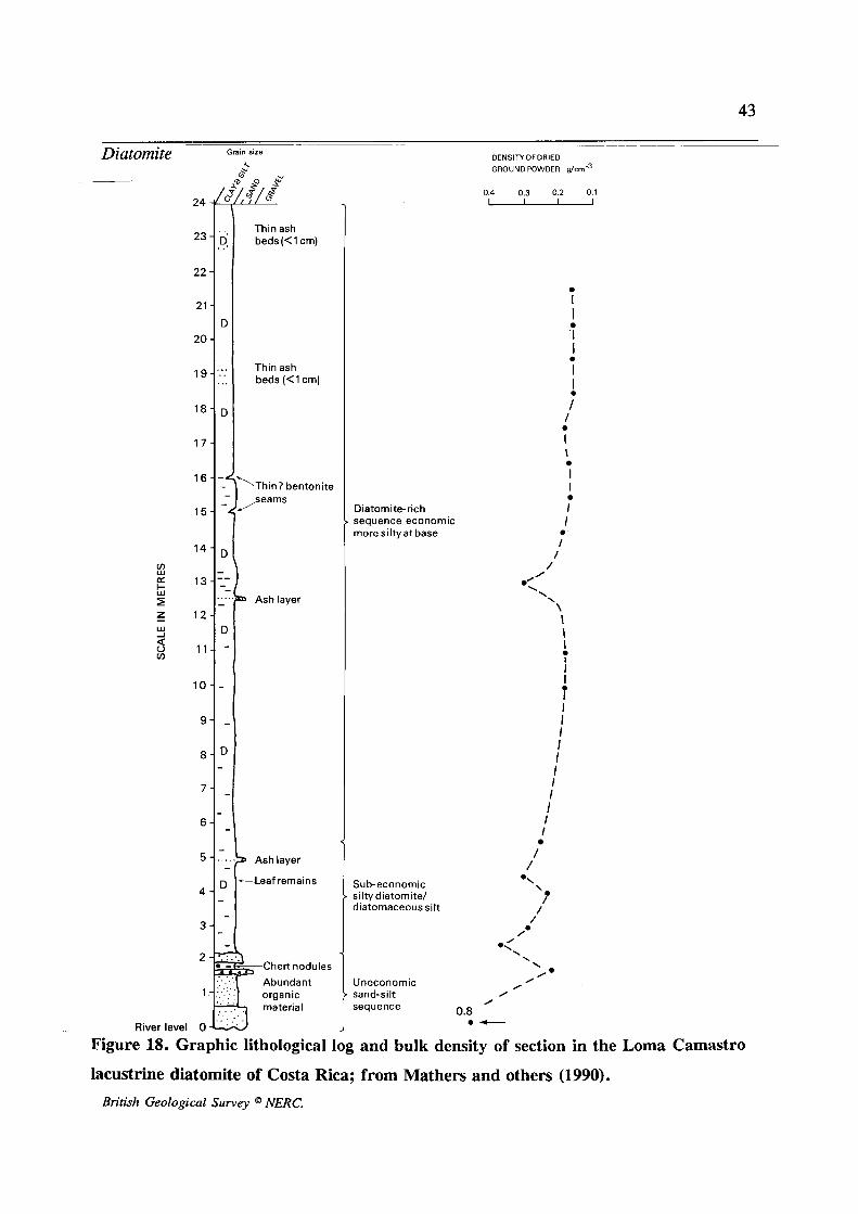
changes in diatomite content (Mathers and others, 1990, see Fig. 18
herein). In general, samples with either a high content of solid
crystalline rock and mineral grains (ie impurities) or a coarse grain
size will have a higher bulk densities; (for a fuller discussion of this
approach see Inglethorpe & Bloodworth, 1989). The SG is a more
reliable guide to quality and can be readily determined in a field
laboratory using the methodology described in the ODA/BGS
Industrial Minerals Laboratory Manual on diatomite by Inglethorpe
(1992). Any carbonate impurities present can be easily detected by
dropping acid on the sample and checking for effervescence.
A portable microscope has been used by experienced exploration
geologists working for some of the major diatomite producers as a
rapid means of screening samples by estimating their purity. In trained
hands an initial appreciation of the diatomite assemblage present can
also be obtained (Kadey, 1983).
British Geological Survey @ NERC.
43
24
23-
22 -
21 -
20 -
1 g -
1 8 -
1 7 -
16--*
15-
1 4 -
13-1-
12 -
1 1 -
10--
9-
8 -
7-
6 -
5
4 -
3-
2
‘
6, . .
D
.::
...
D
- -
D -
... -
D -
.
-
. -
-
D -
-
-= a . . .
Grain size
- River level 0
& & .P
Thin ash beds(<l cm)
Thin ash beds (< 1 cm)
‘Thin? bentonite ,seams
Ashlayer
Ashlayer
-Leaf remains
T C h e r t n o d u l e s Abundant organic
7 material
Diatomite-rich sequence economic more siltyat base
Sub-economic si I ty diatom i t e/ diatomaceous silt
Uneconomic sand-silt sequence 0.8
DENSITYOF DRIED GROUNOPOWDER g / ~ r n - ~
0.4 0.3 0.2 0.1 - I I I I I I I
f
I \
I I
I I
0
0
0
I /
/ 0
\ 0’
\ \
\ \ I I
I I I I I I I I I I I
I I
1
/ /
Figure 18. Graphic lithological log and bulk density of section in the Loma Camastro
lacustrine diatomite of Costa Rica; from Mathers and others (1990). British Geological Survey NERC.
44
Diatomite
Samples are disaggregated in water and spread onto a slide, excess
water is removed by drying or pressing on a cover glass. A
magnification of at least x250 is required; the refractive index of the
diatoms is close to that of water making them difficult to see easily,
although the quantity and nature of mineral impurities are readily
apparent. This difficulty is easily overcome by the addition of a
mounting medium such as Canada Balsam with a markedly different
refractive index. Fuller details and discussion of this technique are
given by Eardley-Wilmot (1928).
In the detailed assessment of diatomites several geophysical techniques
can be deployed. Seismic refraction is particularly useful for
determining the overall form of poorly-consolidated lacustrine deposits
where these occupy basins floored by lavas or more consolidated rocks
(see pers. comm. in Kadey, 1983, page 689.). Given the marked
density contrast between relatively dry diatomite and much denser
intervening layers such as mudstone or limestone, it is perhaps
surprising that gravity surveys have not been utilized in delineating
deposits. The precise nature of modern microgravity techniques should
be suitable for detecting relatively thin beds of diatomite. A further
technique likely to be successful in mapping out diatomite beds within
packets of diverse sediments is the use of portable ground conductivity
meters (Zalasiewicz and others, 1985), which can exploit the different
electromagnetic response of relatively resistive high-purity diatomite
beds from much more conductive clay-rich lithologies. The principal
advantage of these meters is that they can be used to make rapid
surveys in accessible terrain.
Detailed delineation of diatomite deposits and quantification of reserves
British Geological Survey @ NERC.
45
Diatomite
also requires a blend of excavation and drilling to establish the three-
dimensional form of the resource-body .
In dry sediments hand-dug shafts using cheap local labour can be very
effective in investigating poorly-consolidated sediments (see for
example Stearns, 1931). The effective depth of vertical shafts is about
15 m, the sequence can be logged from a wire-cage lowered down the
shaft. Relatively soft sediments can also be investigated using
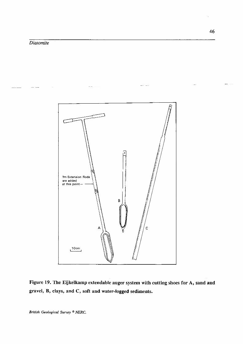
extendable auger systems such as those manufactured by Eijkelkamp
(see Mathers & Zalasiewicz, 1985; Fig. 19). The limit of operation is
normally 5 - 6 m although coarse deposits such as gravels and surficial
pebbly layers considerably reduce the success rate. Where strata are slightly inclined or in areas with some topographic relief, bulldozer-
or hand-dug trenches provide effective means of examining and
sampling the sequence.
Drilling of diatomite-bearing sequences is difficult due to the relatively
poorly-consolidated nature of many deposits. Furthermore the heavily
consolidated variants which might be expected to core well are unlikely
to be of economic interest. Experienced drill crews are required.
Kadey (1983) states that 'little if any, good quality diatomite will
produce satisfactory core with a diameter less than 10 - 15 cm'. Where
diatomite occurs at relatively shallow depths (less than 30m) in wholly
soft or poorly consolidated sequences the use of a percussion (shell and
auger) drilling rig is recommended. Equipped with a 'down the hole
sliding hammer' they can be used recover undisturbed 'U100'
(formerly U4) samples in preparatory steel tubes preferably fitted with
split plastic sample liners to facilitate easy removal and sample
logging. If immediately wrapped in polythene and sealed these samples
British Geological Survey @ NERC.
46
Diatomite
B
Figure 19. The Eijkelkamp extendable auger system with cutting shoes for A, sand and
gravel, B, clays, and C, soft and water-logged sediments.
British Geological Survey @ NERC.