Embed Size (px)
Citation preview

Hervé Barthélémy
Hydrogen storage –Recent Improvements and
Industrial Prospectives
INTERNATIONAL CONFERENCE ON HYDROGEN SAFETY ICHS 2013
September 9 -11, 2013Bruxelles - BELGIUM
The world leader in gases for industry, health and the environment
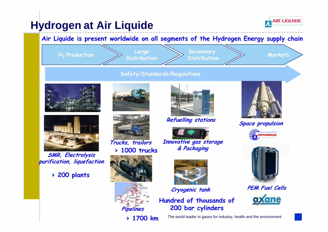
Hydrogen at Air Liquide
H2 ProductionSecondary Distribution
LargeDistribution
Markets
Safety/Standards/Regulations
Air Liquide is present worldwide on all segments of the Hydrogen Energy supply chain
Space propulsion
PEM Fuel Cells
Refuelling stations
Innovative gas storage & Packaging
Trucks, trailors
SMR, Electrolysispurification, liquefaction
> 200 plants
Hundred of thousands of 200 bar cylinders
> 1000 trucks
Cryogenic tank
> 1700 km
Pipelines
The world leader in gases for industry, health and the environment 3
I. COMPRESSED HYDROGEN STORAGE
CASE STUDIES AND APPLICATIONS: HYDROGEN STORAGE AND INDUSTRIAL PROSPECTIVE
II. CRYOGENIC VESSELS FOR THE STORAGE OF LIQUID HYDROGEN
The world leader in gases for industry, health and the environment 4
1. INTRODUCTION AND DIFFERENT TYPES
2. SOME HISTORY
3. DESIGN AND MANUFACTURING
4. SUITABLE MATERIALS FOR PRESSURE VESSELS
I. COMPRESSED HYDROGEN STORAGE
5. NEW TRENDS DUE TO HYDROGEN ENERGY
6. CONCLUSION

The world leader in gases for industry, health and the environment 5
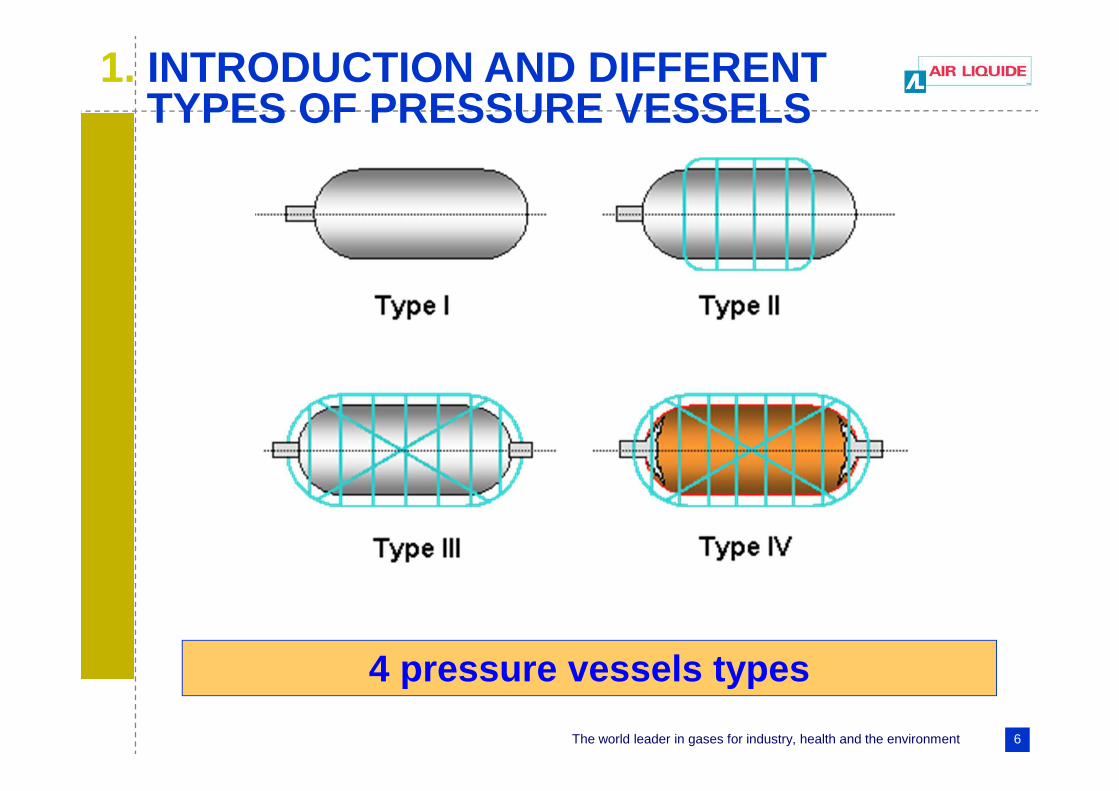
1. INTRODUCTION AND DIFFERENT TYPES OF PRESSURE VESSELS
Type I : pressure vessel made of metal
Type II : pressure vessel made of a thick metallic liner hoop wrapped with a fiber resin composite
Type III : pressure vessel made of a metallic liner fully-wrapped with a fiber-resin composite
Type IV : pressure vessel made of polymeric liner fully-wrapped with a fiber-resin composite
The world leader in gases for industry, health and the environment 6
4 pressure vessels types
1. INTRODUCTION AND DIFFERENT TYPES OF PRESSURE VESSELS

The world leader in gases for industry, health and the environment 7
Different types of pressure vessels
Type I cylinder Type II vessel Type III or IV vessel
Toroid composite vessel
1. INTRODUCTION AND DIFFERENT TYPES OF PRESSURE VESSELS

The world leader in gases for industry, health and the environment 8
Gas transport - 1857
2. SOME HISTORY
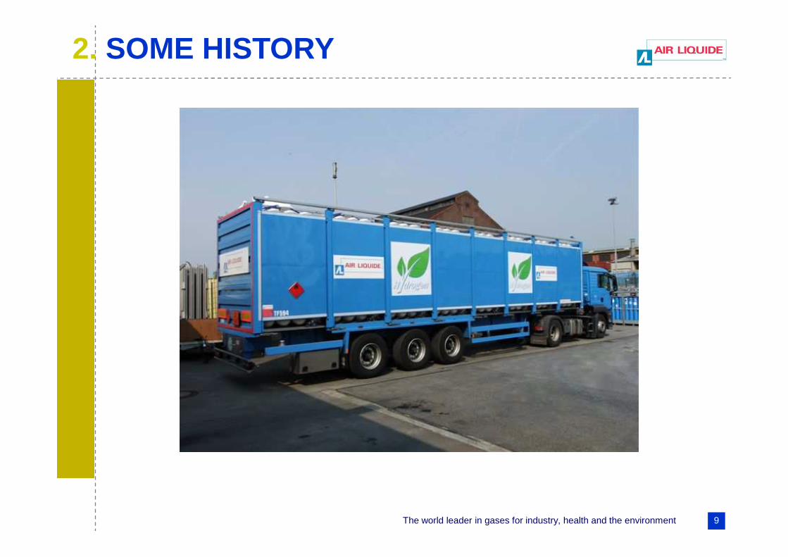
The world leader in gases for industry, health and the environment 9
2. SOME HISTORY
The world leader in gases for industry, health and the environment 10
� The experimentation of composite vessels started in the 50s
� Composite vessels were introduced for space and military applications
2. SOME HISTORY

The world leader in gases for industry, health and the environment 11
3. DESIGN AND MANUFACTURING
� Metallic vessels and composite vessels are very different :
• The metal is isotropic, the composite is anisotropic
• The failure modes are different
• The ageing is different
The world leader in gases for industry, health and the environment 12
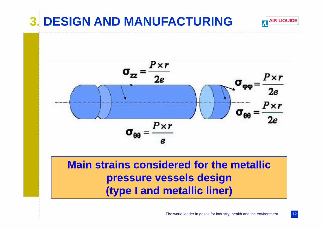
3. DESIGN AND MANUFACTURING
Main strains considered for the metallic pressure vessels design (type I and metallic liner)
The world leader in gases for industry, health and the environment 13
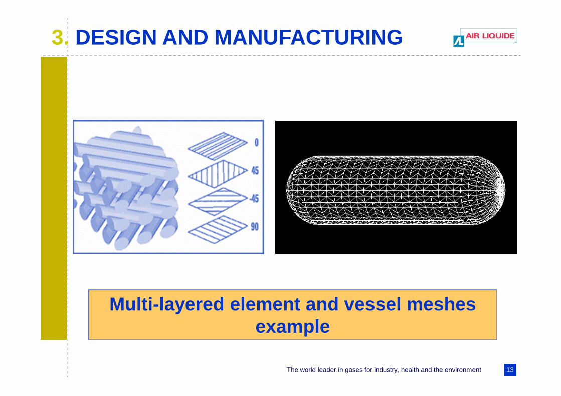
3. DESIGN AND MANUFACTURING
Multi-layered element and vessel meshes example

The world leader in gases for industry, health and the environment 14
3. DESIGN AND MANUFACTURING
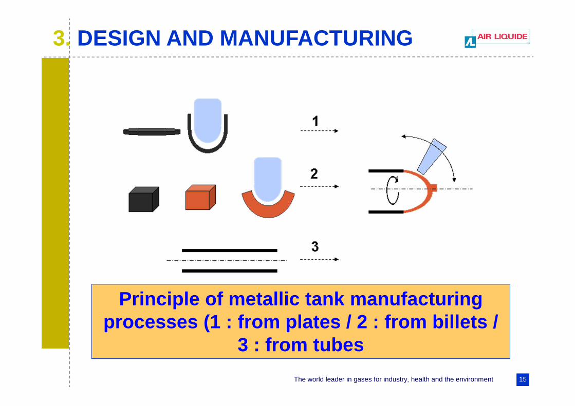
� Type I :
• From plates
• From billets
• From tubes
3 different manufacturing processes
The world leader in gases for industry, health and the environment 15
3. DESIGN AND MANUFACTURING
Principle of metallic tank manufacturing processes (1 : from plates / 2 : from billets /
3 : from tubes
The world leader in gases for industry, health and the environment 16
3. DESIGN AND MANUFACTURING
• From the polymer or the monomers by the rotomolding process
• From tubes : polymeric tubes (made by extrusion blow moding)
� Polymers liners :
The world leader in gases for industry, health and the environment 17
3. DESIGN AND MANUFACTURING
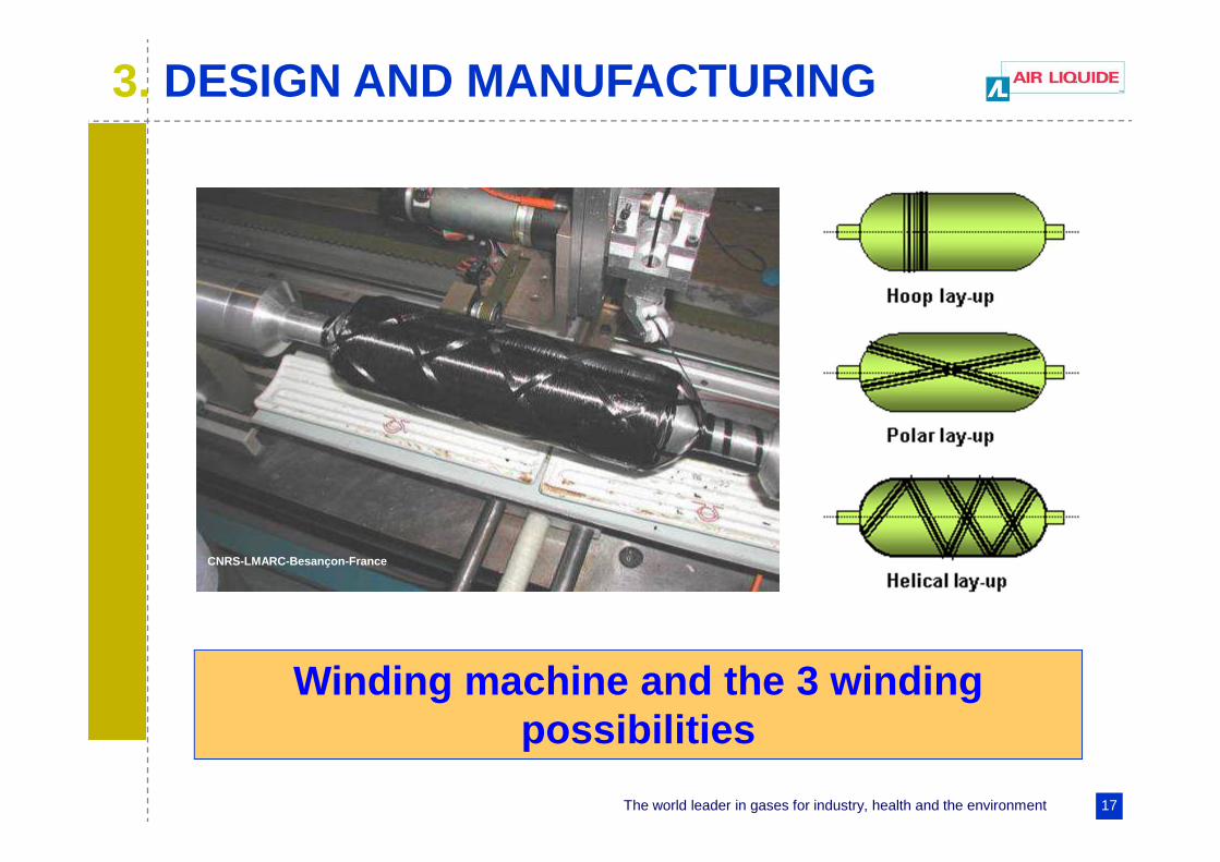
Winding machine and the 3 winding possibilities
CNRS-LMARC-Besançon-France

The world leader in gases for industry, health and the environment 18
4. SUITABLE STEELS FOR HYDROGEN HIGH PRESSURE VESSELS
� Risk of hydrogen embrittlement :
• Environment
• Material
• Design and surface conditions
The world leader in gases for industry, health and the environment 19
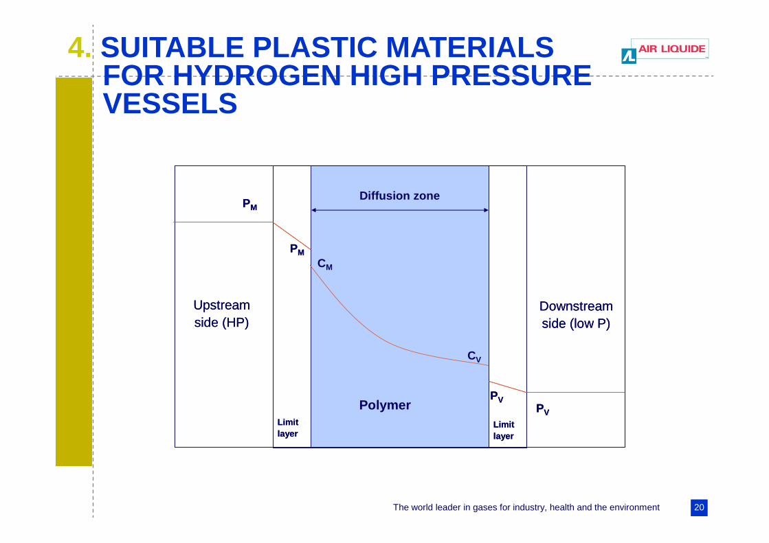
� Permeation rate through the polymeric liner :
� Permeation is specific of type IV vessels. It is th e result of the H 2 gas dissolution and diffusion in the polymer matrix
� H2 is a small molecule, and thus the permeation is enhanced. This leads to the development of special polymers
� Polyethylene and polyamide are the most used liners for type IV tanks
4. COMPOSITE CYLINDERS –SUITABLE MATERIALS
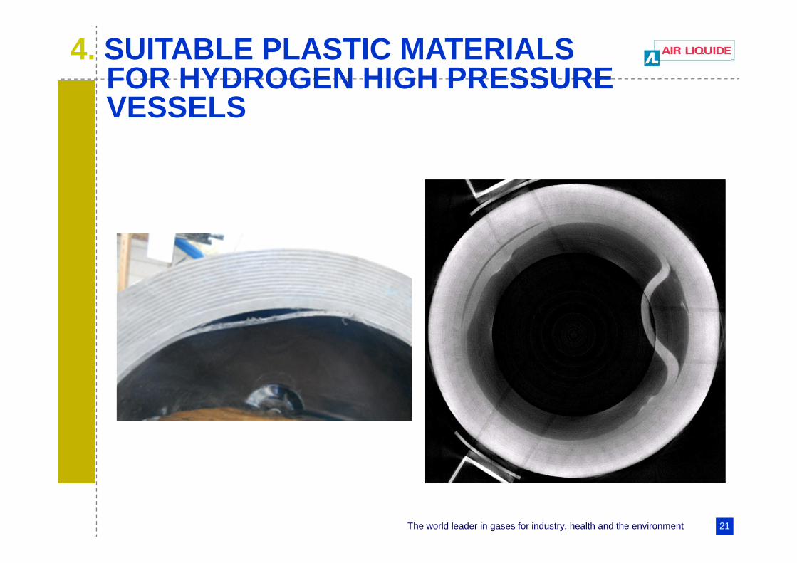
� One phenomena to avoid is the blistering of liner collaps
The world leader in gases for industry, health and the environment 20
4. SUITABLE PLASTIC MATERIALS FOR HYDROGEN HIGH PRESSURE VESSELS
Upstreamside (HP)
Downstreamside (low P)
Polymer
PM
PV
PM
PV
Limitlayer
Limitlayer
CM
CV
Upstreamside (HP)
Downstreamside (low P)
Polymer
PM
PV
PM
PV
Limitlayer
Limitlayer
CM
CV
Diffusion zone
The world leader in gases for industry, health and the environment 21
4. SUITABLE PLASTIC MATERIALS FOR HYDROGEN HIGH PRESSURE VESSELS
The world leader in gases for industry, health and the environment 22
� Specific issues:
4. SUITABLE MATERIALS FOR ALUMINIUM ALLOY
�Presence of mercury into H 2
� Influence of tap water which
reduces significantly the
pressure cycling life
The world leader in gases for industry, health and the environment 23
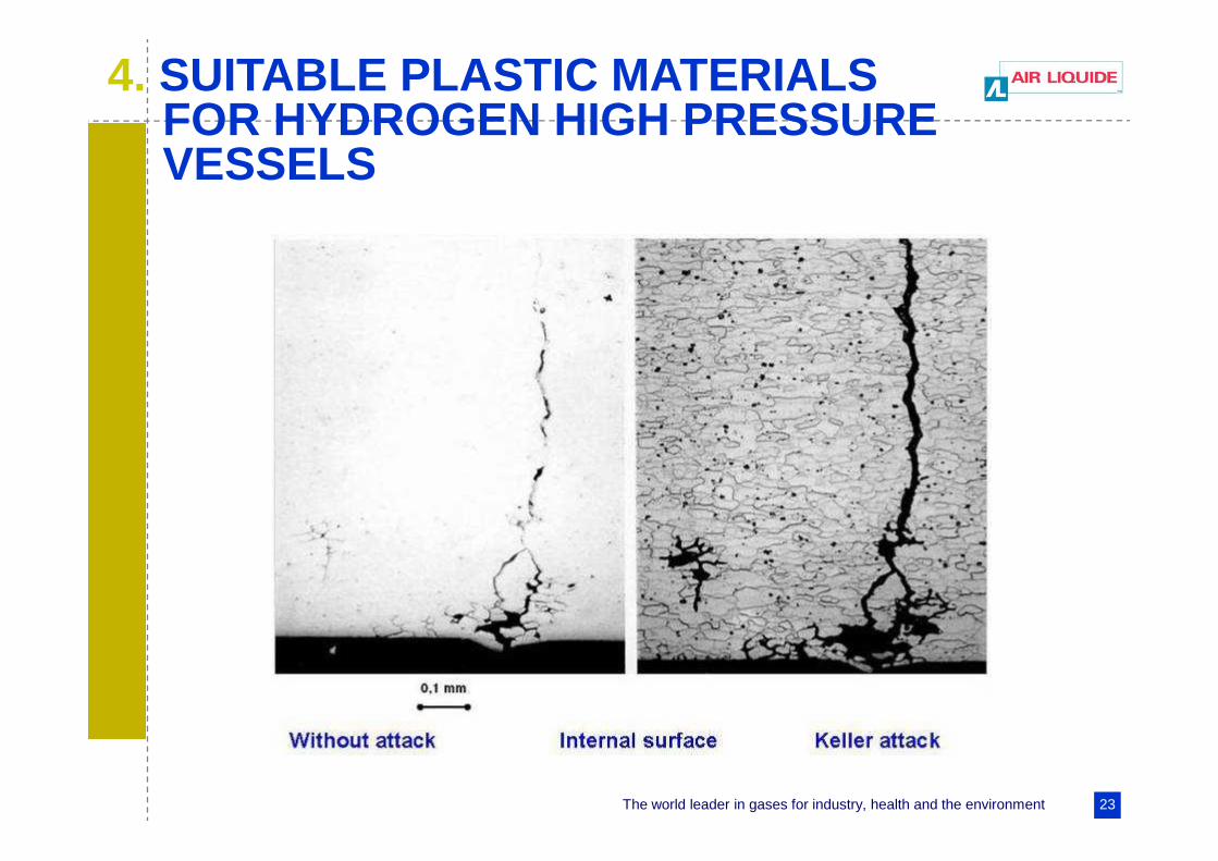
4. SUITABLE PLASTIC MATERIALS FOR HYDROGEN HIGH PRESSURE VESSELS
The world leader in gases for industry, health and the environment 24
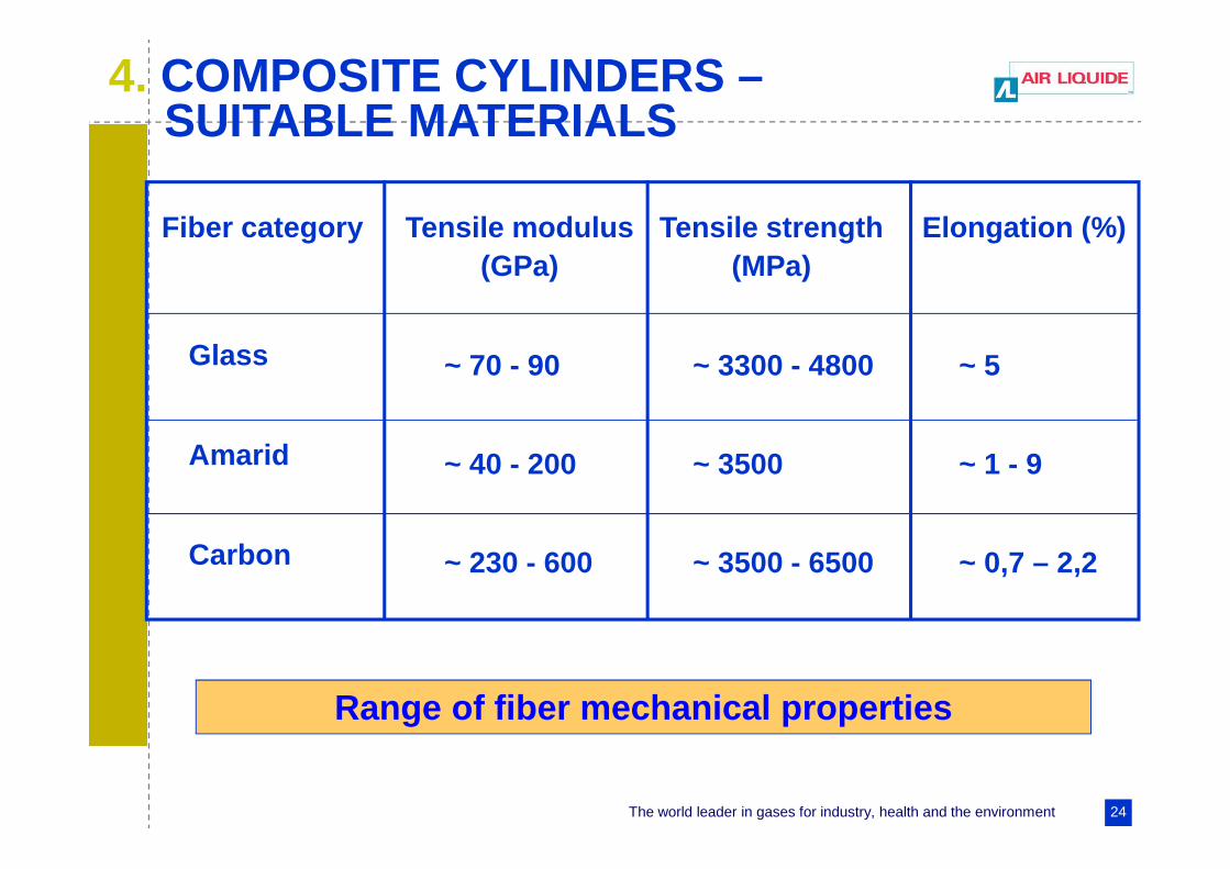
Range of fiber mechanical properties
Fiber category
Glass
Amarid
Carbon
~ 70 - 90
Tensile modulus(GPa)
Tensile strength(MPa)
Elongation (%)
~ 40 - 200
~ 230 - 600
~ 3300 - 4800
~ 3500
~ 3500 - 6500
~ 5
~ 1 - 9
~ 0,7 – 2,2
4. COMPOSITE CYLINDERS –SUITABLE MATERIALS

The world leader in gases for industry, health and the environment 25
4. MATERIALS SUITABLE FOR HYDROGEN HIGH PRESSURE VESSELS
Hydrogen requires special attention for the choice of :
For type IV, permeation measurement is required (e.g. specified rate < 1 cm 3/l/h).
Material test generally requested to check “H 2 embrittlement”
• the polymer (type IV tanks)
• the steel (types I, II and III tanks)

The world leader in gases for industry, health and the environment 26
5. TYPES I AND II CYLINDERS FORSTATIONARY APPLICATIONS
The world leader in gases for industry, health and the environment 27
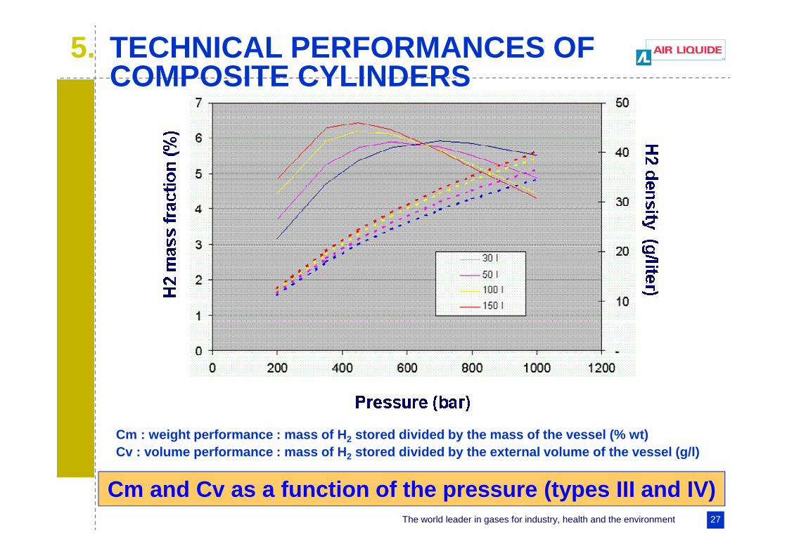
Cm and Cv as a function of the pressure (types III and IV)
Cm : weight performance : mass of H 2 stored divided by the mass of the vessel (% wt)Cv : volume performance : mass of H 2 stored divided by the external volume of the vessel (g/l)
5. TECHNICAL PERFORMANCES OF COMPOSITE CYLINDERS

The world leader in gases for industry, health and the environment 28
6. COMPRESSED GAS STORAGE -CONCLUSION
Main features for H 2 pressure vessel types in 2006
Type I
Type II
Type III
Type IV
Technology mature
Cost performance
Weight performance
++ Pressure limited to
500 bar (⇒⇒⇒⇒ density : –)
+ Pressure not limited
(⇒⇒⇒⇒ density : +)
For P < 350 bar; (difficulty to pass pressure cycling
requirement for 700)
For P < 350 bar; (700 bar under development )
++
+
–
– +
+
–
0
The world leader in gases for industry, health and the environment 29
1. INTRODUCTION (COMPARISON OF EFFICIENCY/GROWS STORAGE)
2. DIFFERENT TYPES OF CRYOGENIC VESSELS
3. REDUCING THE WALL THICKNESS OF THE VESSELS
II. CRYOGENIC VESSELS FOR THE STORAGE OF LIQUID HYDROGEN
4. TRANSPORT OF LIQUID HYDROGEN
5. MATERIAL ISSUES
The world leader in gases for industry, health and the environment 30
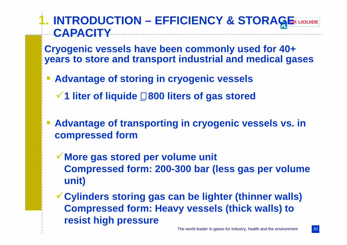
1. INTRODUCTION – EFFICIENCY & STORAGE CAPACITY
Cryogenic vessels have been commonly used for 40+ years to store and transport industrial and medical gases
� Advantage of storing in cryogenic vessels
� Advantage of transporting in cryogenic vessels vs. in compressed form
�1 liter of liquide ∼∼∼∼ 800 liters of gas stored
�More gas stored per volume unitCompressed form: 200-300 bar (less gas per volume unit)
�Cylinders storing gas can be lighter (thinner walls ) Compressed form: Heavy vessels (thick walls) to resist high pressure
The world leader in gases for industry, health and the environment 31
1. INTRODUCTION – EFFICIENCY & STORAGE CAPACITY
Cryogenic vessels have been commonly used for 40+ years to store and transport industrial and medical gases
� Disadvantages of cryogenic vessels:
�Gases (especially H 2) must be refrigerated down to very low temperatures to be in liquid form
See gas/liquid temperature equilibrium for differen t gases at atmospheric pressure on slide 32)
�At such low temperatures, gases must be stored in high efficiency (vacuum) insulated vessels

The world leader in gases for industry, health and the environment 32
1. INTRODUCTION (COMPARISON OF EFFICIENCY/GROWS STORAGE)
Gases Kr O2 Ar Air N2 Ne H2 He
Boiling
Temperature - 153 - 183 - 186 - 191 - 196 - 246 - 253 - 269
BOILING TEMPERATURES (°C) AT ATMOSPHERIC PRESSURE OF DIFFERENT
GASES

The world leader in gases for industry, health and the environment 33
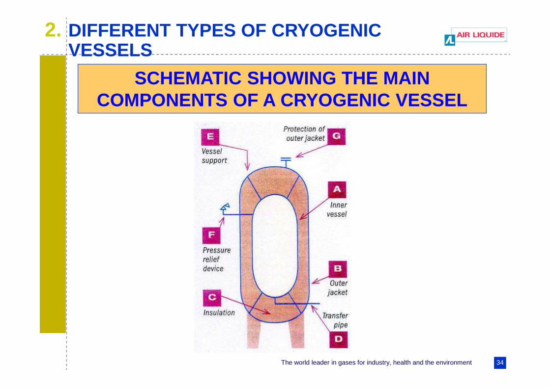
Cryogenic vessels used for gases requiring low temperature for liquefaction are normally:
� Vacuum -insulatedand
� Composed of an inner pressure vessel and an external protective jacket
Thermal conductivity of the space between the inner vessel and the outer jacket is reduced by using eit her:
� Perlite (powder structure)or
� Super insulation (wrapping with layers of aluminum film)
2. DIFFERENT TYPES OF CRYOGENIC VESSELS
The world leader in gases for industry, health and the environment 34
2. DIFFERENT TYPES OF CRYOGENIC VESSELS
SCHEMATIC SHOWING THE MAIN COMPONENTS OF A CRYOGENIC VESSEL
The world leader in gases for industry, health and the environment 35
� CO2 and N2O (and other gases with relatively high liquefaction temperature)
�Non-vacuum insulated vessels are used�Vessel insulation is normally a thick layer of
polyurethane
2. DIFFERENT TYPES OF CRYOGENIC VESSELS
� Gas storage
Cryogenic vessels are used to store gases at production sites and end-user sites.
The world leader in gases for industry, health and the environment 36
� Large transportable cryogenic vessels are used to fill and/or transport gases
�Cryogenic trailers: Refilling stationary vessels at end -user sites.
�Large containers: Road, railroad and sea transportation
2. DIFFERENT TYPES OF CRYOGENIC VESSELS
The world leader in gases for industry, health and the environment 37
� Small cryogenic vessels (< 1 000 liters water capacity) are filled and transported by suppliers of industrial or medical gas to end-users
� A large number of cryogenic vessels are in use worldwide
2. DIFFERENT TYPES OF CRYOGENIC VESSELS
The world leader in gases for industry, health and the environment 38
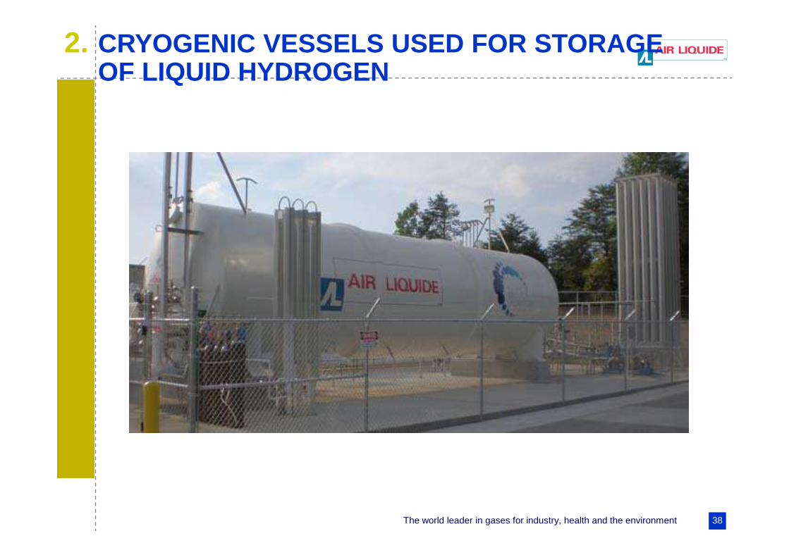
2. CRYOGENIC VESSELS USED FOR STORAGE OF LIQUID HYDROGEN

The world leader in gases for industry, health and the environment 39
2. DIFFERENT TYPES OF CRYOGENIC VESSELS
The world leader in gases for industry, health and the environment 40
2. DIFFERENT TYPES OF CRYOGENIC VESSELS
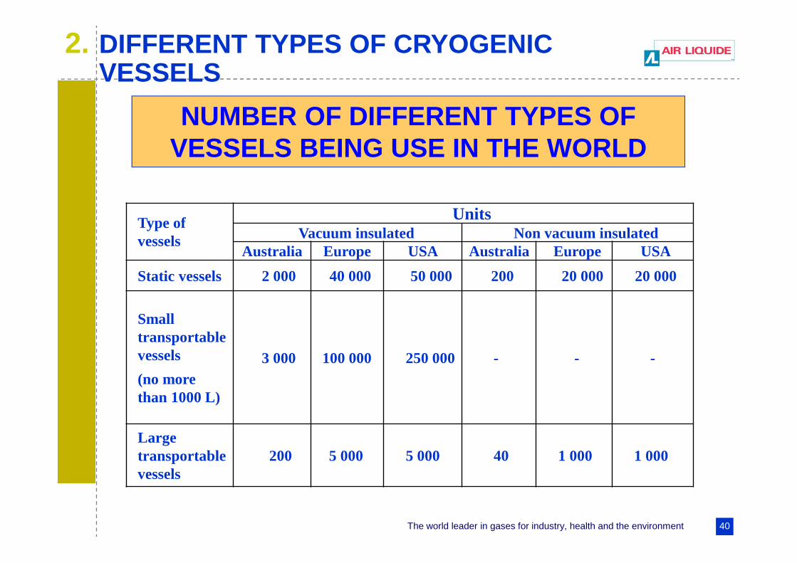
NUMBER OF DIFFERENT TYPES OF VESSELS BEING USE IN THE WORLD
Type of vessels
UnitsVacuum insulated Non vacuum insulated
Australia Europe USA Australia Europe USA
Static vessels 2 000 40 000 50 000 200 20 000 20 000
Small transportable vessels
(no more than 1000 L)
3 000 100 000 250 000 - - -
Large transportable vessels
200 5 000 5 000 40 1 000 1 000
The world leader in gases for industry, health and the environment 41
3. REDUCING VESSEL WALL THICKNESS
� Modern methods based on cold stretching (use of cold properties) are widely used in Europe but are still not fully accepted in North America and Japan .
� These methods considerably reduce vessel wall thickness in stationary cryogenic vessels.
� Design and manufacturing improvements limit the quantity of expensive materials (e.g. stainless ste el) used and thus reduce vessel price.

The world leader in gases for industry, health and the environment 42
3. REDUCING THE WALL THICKNESS OF THE VESSELS
� The principle and detail information on the cold stretching method is given in paper “An overview of RCS for hydrogen pressure vessels”
� All efforts were made to produce efficient ISO standards for stationary cryogenic vessels in an expedient manner. ISO 21009-2, Cryogenic vessels –Static vacuum insulated vessels – Part 2: Operationa l requirements, is already available, while ISO 2 100 9-1, Cryogenic vessels – Static vacuum -insulated vessels completed and waiting to be issued in the coming months

The world leader in gases for industry, health and the environment 43
4. TRANSPORT OF LIQUID HYDROGEN
� In order to reduce the volume required to store a
useful amount of hydrogen - particularly for
vehicles - liquefaction may be employed. Since
hydrogen does not liquefy until it reaches - 253° C
(20 degrees above absolute zero), the process is
both time consuming and energy intensive
demanding. Up to 40 % of the energy content in the
hydrogen can be lost (in comparison with 10 %
energy loss with compressed hydrogen).
The world leader in gases for industry, health and the environment 44
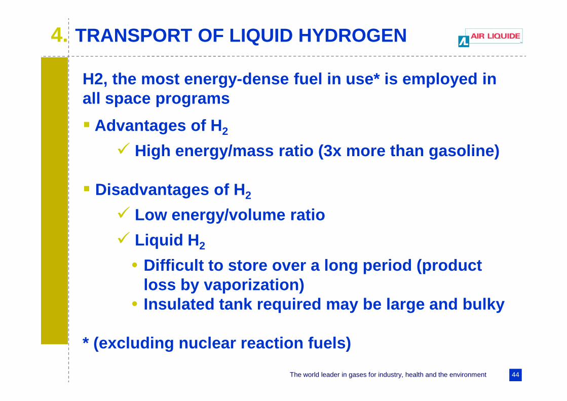
H2, the most energy-dense fuel in use* is employed in all space programs
� Advantages of H 2
� High energy/mass ratio (3x more than gasoline)
� Disadvantages of H 2
� Low energy/volume ratio
� Liquid H 2
• Difficult to store over a long period (product loss by vaporization)
• Insulated tank required may be large and bulky
* (excluding nuclear reaction fuels)
4. TRANSPORT OF LIQUID HYDROGEN

The world leader in gases for industry, health and the environment 45
� At room temperature,
INFLUENCE OF TEMPERATURE - PRINCIPLE
5. MATERIAL ISSUES – HYDROGEN EMBRITTLEMENT
The world leader in gases for industry, health and the environment 46
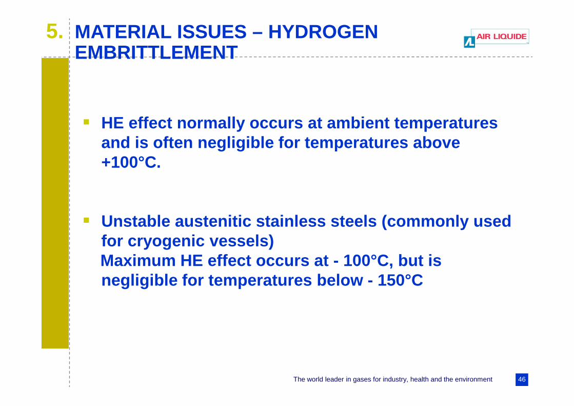
� HE effect normally occurs at ambient temperatures and is often negligible for temperatures above +100°C.
� Unstable austenitic stainless steels (commonly used for cryogenic vessels)Maximum HE effect occurs at - 100°C, but is negligible for temperatures below - 150°C
5. MATERIAL ISSUES – HYDROGEN EMBRITTLEMENT

The world leader in gases for industry, health and the environment 47
INFLUENCE OF TEMPERATURE FOR SOME STAINLESS STEELS
5. MATERIAL ISSUES – HYDROGEN EMBRITTLEMENT
The world leader in gases for industry, health and the environment 48
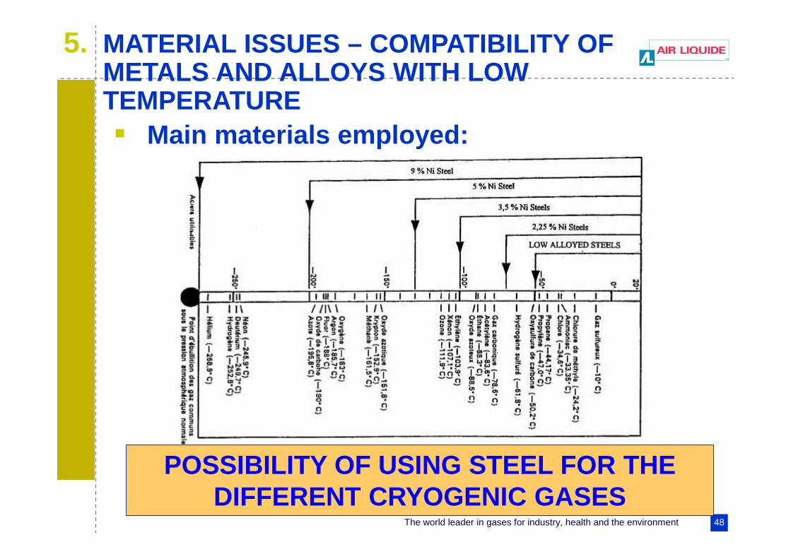
5. MATERIAL ISSUES – COMPATIBILITY OF METALS AND ALLOYS WITH LOW TEMPERATURE� Main materials employed:
POSSIBILITY OF USING STEEL FOR THE DIFFERENT CRYOGENIC GASES

The world leader in gases for industry, health and the environment 49
5. MATERIAL ISSUES – COMPATIBILITY OF METALS AND ALLOYS WITH LOW TEMPERATURE
� Use of metal at low temperatures entails special problems which must be resolved, in particular:
�Changes in mechanical characteristics, �Expansion and contraction phenomena �Thermal conduction of materials
� Brittleness – The most critical problem It can effect certain metallic equipment used at cryogenic temperatures

The world leader in gases for industry, health and the environment 50
5. MATERIAL ISSUES – COMPATIBILITY OF METALS AND ALLOYS WITH LOW TEMPERATURE
� In what follows, we shall only deal ferritic
steels, stainless steels and aluminium
alloys, which are the main materials used
at low temperatures

The world leader in gases for industry, health and the environment 51
5. MATERIAL ISSUES – COMPATIBILITY OF METALS AND ALLOYS WITH LOW TEMPERATURE
CHARPY TEST
The world leader in gases for industry, health and the environment 52
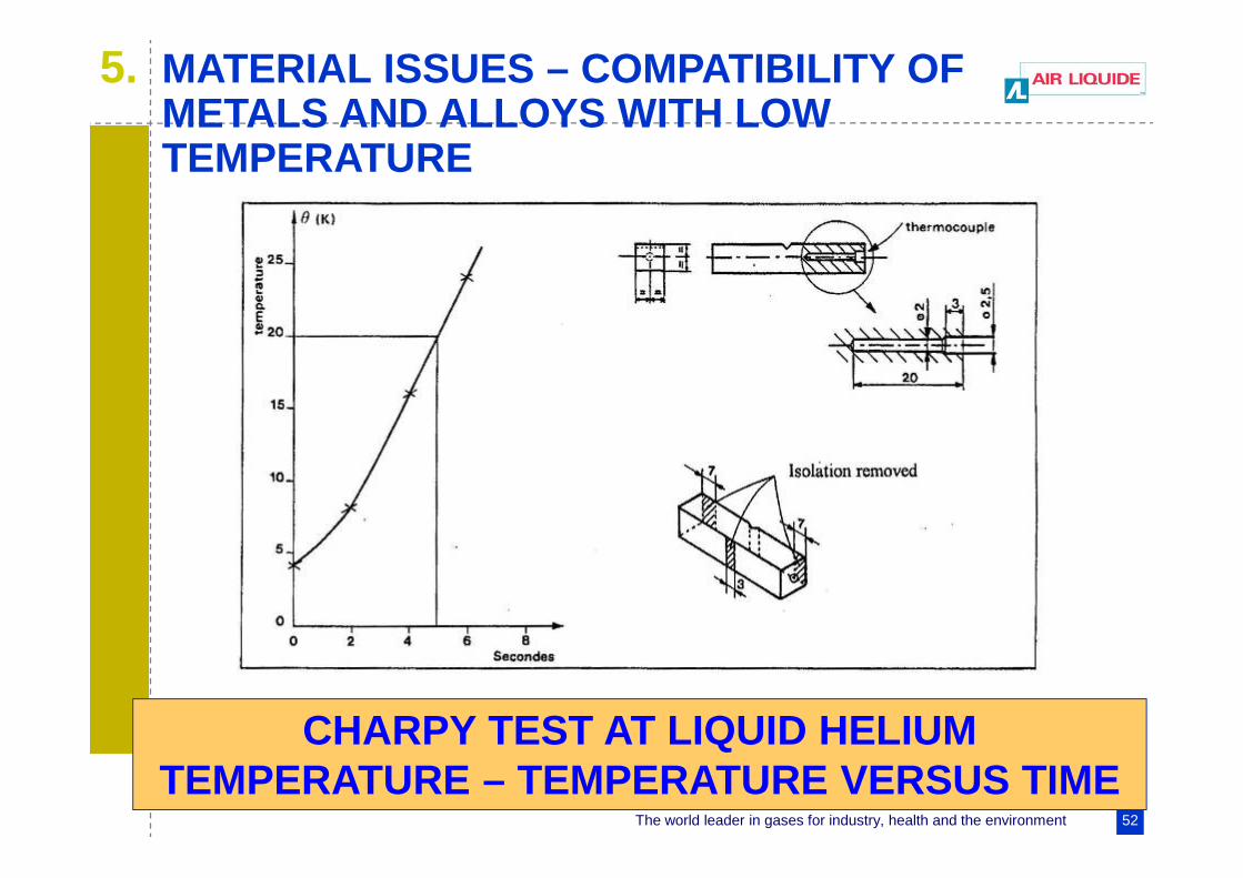
5. MATERIAL ISSUES – COMPATIBILITY OF METALS AND ALLOYS WITH LOW TEMPERATURE
CHARPY TEST AT LIQUID HELIUM TEMPERATURE – TEMPERATURE VERSUS TIME