Embed Size (px)
Citation preview

International Biofuels Strategy Project
November 2007
Project 08/017
Dr Geraint Evans
Liquid Transport Biofuels - Technology Status Report

The National Non-Food Crops Centre Building sustainable supply chains
NNFCC, the UK’s single independent authority on renewable materials and technology
Helping get products to market by building and strengthening supply chains
Supporting decision makers with comprehensive information resources from all sectors The National Non-Food Crops Centre Biocentre, York Science Park, Innovation Way, Heslington York YO10 5DG, UK Tel: +44 (0)1904 435182 [email protected] www.nnfcc.co.uk

Liquid Transport Biofuels - Technology Status Report, NNFCC, 2007
Page 1
International Biofuels Strategy Project
Liquid Transport Biofuels - Technology Status Report
Geraint Evans NNFCC
EXECUTIVE SUMMARY
Biofuel production in the UK is becoming established, driven mainly by climate change,
energy security and declining fossil fuel supplies. In the UK, fatty acid methyl ester (FAME)
biodiesel production is developing (with ongoing opportunities for continuous improvement
by incorporating new process developments and technologies) while first generation
ethanol production from sugar beet and wheat is emerging with just the one 55,000
tonnes/year plant currently in operation. However, the industry is threatened by a number
of issues including “splash and dash” and sustainability issues which are affecting investor
confidence.
High vegetable oil prices are causing economic difficulties for biodiesel producers both in
the UK and some other parts of the world at present while it is not clear whether current
high wheat prices will limit the numbers of first generation bioethanol plants which move
from planning to construction and operation.
Synthetic fuels (diesel for road transport and jet fuel for aviation) produced via the
thermochemical biomass to liquids (BTL) route provide the most suitable fuel blendstocks
for incorporation into the UK general transport fuel pool and, of the near term biofuel
technologies, one of the highest greenhouse gas reduction potentials. Capital cost,
however, is a significant barrier to the development of UK production facilities. This
technology, on a world-wide basis, should be considered to be now moving from pilot to
demonstration scale. For example:
Choren Industries in Germany are about to start production at their 15,000 tonnes/year Beta plant in Freiberg, Germany.
Flambeau Paper Mill in Wisconsin, USA have just announced (28th November 2007) that they plan to build a 16,500 tonnes/year demonstration plant to produce Fischer-Tropsch wax, which will be sold on to oil refineries for subsequent upgrading to synthetic fuels – the plant is expected to be complete in 2010.
Range Fuels recently announced (November 2007) the start of construction of a 113,000 tonnes/year thermochemical ethanol production facility in Georgia, USA.
Stora Enso in collaboration with Neste (Finland) is building a demonstration plant at Stora Enso’s Varkaus paper mill.

Liquid Transport Biofuels - Technology Status Report, NNFCC, 2007
Page 2
In addition to synthetic fuel, the BTL route also produces a paraffinic naphtha which, when
cracked, maximises the production of the most valuable ethylene and propylene streams,
which are further processed to make products such as renewable polyethylene and
polypropylene. For the UK, therefore, it may be advantageous to locate a BTL facility near
to an existing cracker such as that located at Wilton, Teesside.
Lignocellulosic ethanol production via fermentation is about to be demonstrated in the UK,
the USA and Denmark. The UK developers, however, are likely in the first instance to
commercially develop the process in the USA where financial assistance is available from the
US government. In the USA, six large scale lignocellulosic ethanol plants are being built with
DOE assistance ranging in capacity from 30,000 to 113,000 tonnes/year. However, further
work is still needed in the areas of developing improved raw feedstocks (eg more digestible
crops), pretreatments, enzymes and fermentation organisms. In particular, due to the
different types of carbohydrates contained in biomass, a range or suite of advanced
enzymes/microbes will be required for biomass hydrolysis and fermentation; this package
represents a significant process cost and requires optimisation.
Other technologies which are respectively commercial and emerging include the vegetable
oil hydrogenation route and pyrolysis. Vegetable oil hydrogenation takes a “first
generation” feedstock but makes a high quality “second generation” diesel product which is
easily blended into the existing diesel fuel pool, unlike FAME biodiesel made from vegetable
oils, which have certain limitations with respect to their use in engines. The process used is
a good fit for oil refiners, especially given that they well understand the process, both
economically and technically. There are currently five developers of who perhaps Neste Oil
in Finland are most advanced.
Of all the technologies reviewed in this report, biomass pyrolysis is the cheapest process to
install but it produces the most difficult product to incorporate into the existing fuel pool.
One solution being driven is to upgrade the pyrolysis oil so that it can be fed into an existing
oil refinery – the products would then appear across the range of refinery products from
refinery fuel gas up to perhaps the mid distillates (diesel range). The timescale on this
development is not clear. An alternative use is to develop a system of satellite pyrolysis
plants which would “densify” biomass close to its point of production. This would permit
more economic transport of biomass over longer distances which would in turn, permit
economy of scale benefits to be realised in designing a centralised advanced biofuel facility
which would produce a more valuable, and more easily blended finished fuel such as
synthetic diesel or ethanol.
This report provides a technology status report for advanced liquid biofuels. Pros and cons
of each technology are provided along with discussion on comparative economics,
timescales, scales of operation, greenhouse gas savings and comparative land use
effectiveness.

Liquid Transport Biofuels - Technology Status Report, NNFCC, 2007
Page 3
The existing NNFCC reports by AMEC, Nexant and Tamutech have been used as the
backbone of the report. Information gained from news reports, conferences presentations,
reports and discussions with the technology providers have been added to bring the
information up to date as of 30th November 2007.
A rapid understanding of the key points from the technology assessment section can be
gained by referring to the mindmap summaries presented in Appendix 1 –the more detailed
mindmaps used in preparing this report are available separately.

Liquid Transport Biofuels - Technology Status Report, NNFCC, 2007
Page 4
Contents Executive Summary .................................................................................................................... 1
1.0 Context and Rationale .................................................................................................... 8
2.0 Introduction to the UK Road Transport Fuels Market .................................................... 9
3.0 Drivers for Biofuels ....................................................................................................... 11
4.0 Biofuel Volumes and Technologies Required to Meet UK Targets ............................... 12
5.0 Technology Assessment - Current Biofuels and Production in the UK ......................... 14
5.1 First Generation Biodiesel - FAME ............................................................................ 14
5.1.1 Fuel Quality ........................................................................................................ 16
5.1.2 SWOT Analysis of First Generation Biodiesel (FAME) (1) .................................. 17
5.1.3 FAME Process Developments ............................................................................ 17
5.1.4 Advanced processes ........................................................................................... 18
5.1.5 Glycerine by-product ......................................................................................... 18
5.2 First Generation Bioethanol ...................................................................................... 19
5.2.1 Fuel Quality ........................................................................................................ 21
5.2.2 SWOT Analysis for First Generation Bioethanol ................................................ 24
5.2.3 First Generation Ethanol Process Improvements .............................................. 24
6.0 Technology Assessment - Emerging Technologies ....................................................... 26
6.1 Biochemical (Fermentation) Based Processes .......................................................... 26
6.1.1 Lignocellulosic Ethanol ....................................................................................... 26
6.1.2 Biobutanol .......................................................................................................... 45
6.1.3 Furanics (21) ....................................................................................................... 47
6.2 Thermochemical Based Processes ............................................................................ 48
6.2.1 Vegetable Oil Hydrogenation ............................................................................. 48
6.2.2 Biomass Pyrolysis for the Production of Liquid Fuels (1) ................................... 52
6.2.3 Biomass to Liquids (BTL) .................................................................................... 62
6.2.4 Other Biofuels Derived from Synthesis Gas (2) ................................................. 77
7.0 DISCUSSION ................................................................................................................... 83
7.1 Scale of Operation by Technology ............................................................................ 83
7.2 Estimated Technology Timescales ............................................................................ 85
7.2.1 Butanol ............................................................................................................... 86

Liquid Transport Biofuels - Technology Status Report, NNFCC, 2007
Page 5
7.2.2 Furanics .............................................................................................................. 86
7.2.3 Lignocellulosic Ethanol ....................................................................................... 86
7.25 Pyrolysis ................................................................................................................. 87
7.2.6 Biomass to Liquids ............................................................................................. 87
7.3 Economics.................................................................................................................. 88
7.3.1 Vegetable Oil Hydrogenation Economics (1) ..................................................... 89
7.3.2 Pyrolysis Economics ........................................................................................... 90
7.3.3 Lignocellulosic technologies .............................................................................. 91
7.4 Greenhouse Gas Savings (GHG) ................................................................................ 94
7.4.1 Comparison of Transport Fuels .......................................................................... 94
7.4.2 Comparison with Electricity from Biomass ........................................................ 96
7.5 Comparative Land Use Effectiveness ........................................................................ 97
8.0 Summary ..................................................................................................................... 104
8.1 Fermentation Processes .......................................................................................... 104
8.2 Thermochemical Processes ..................................................................................... 105
8.3 UK Future Direction ................................................................................................. 105
Works Cited ............................................................................................................................ 107
Appendix 1 – Mindmaps ........................................................................................................ 115
Appendix 2 – Summary of Biofuel Properties ........................................................................ 123
Appendix 3 - Opportunities, drivers, barriers/status and UK Activity Tables (2) .................. 124
List of Tables
TABLE 1 ESTIMATED BIOFUEL TONNAGES REQUIRED BY UK (1) ............................................................................... 12
TABLE 2 QUALITATIVE EVALUATION OF SELECTED PRETREATMENT TECHNOLOGIES (2) ................................................. 32
TABLE 3 LIGNOCELLULOSIC PLANT ACTIVITY ACROSS THE WORLD (2) ....................................................................... 42
TABLE 4 PYROLYSIS OIL HYDROCRACKING - YIELDS (31) ......................................................................................... 60
TABLE 5 GASIFICATION PLATFORM PROVIDERS FOR SYNGAS (3) ............................................................................... 67
TABLE 6 GASIFIER SUMMARY (2) ....................................................................................................................... 68
TABLE 7 FT SUPPLIERS AND PROCESS TYPES (41) .................................................................................................. 70
TABLE 8 OTHER TRANSPORT FUELS PRODUCED FROM BIO-DERIVED SYNTHESIS GAS ..................................................... 79
TABLE 9 RELATIVE SCALES OF OPERATION BY TECHNOLOGY ..................................................................................... 84
TABLE 10 BTL TECHNOLOGY STATUS SUMMARY ..................................................................................................... 88
TABLE 11 APPROXIMATE COST LEVELS FOR BIOFUEL TECHNOLOGIES (1) (52) (3) .......................................................... 89
TABLE 12 VEGETABLE OIL HYDROGENATION SUMMARY (1) ....................................................................................... 90

Liquid Transport Biofuels - Technology Status Report, NNFCC, 2007
Page 6
TABLE 13 BIOMASS PYROLYSIS TECHNOLOGY SUMMARY (1) ...................................................................................... 91
TABLE 14 LITRES OF DIESEL EQUIVALENT CALCULATION - SCENARIOS .......................................................................... 98
TABLE 15 REPORT BIOMASS TO LIQUIDS ENERGY CONVERSION EFFICIENCIES (61) ......................................................... 99
List of Figures
FIGURE 1 LOCATIONS OF UK FUELS REFINERIES AND EFFECTIVE DISTRIBUTION RANGES (3) .............................................. 9
FIGURE 2 UK PETROLEUM PRODUCTS PRODUCTION AND DEMAND 2006 (4) .............................................................. 10
FIGURE 3 HISTORIC AND PREDICTED ANNUAL UK ROAD TRANSPORT FUEL DEMAND (3) ................................................ 11
FIGURE 4 DEMAND FOR ROAD TRAVEL (4) ............................................................................................................ 11
FIGURE 5 BIODIESEL GENERATIONS - ILLUSTRATIVE MARKET SHARE EVOLVEMENT (4) ................................................... 13
FIGURE 6 US ETHANOL PRODUCTION (5) .............................................................................................................. 13
FIGURE 7 SUMMARY OF FAME PRODUCTION FROM OILSEED RAPE ........................................................................... 15
FIGURE 8 QUALITATIVE SUMMARY OF FAME BIODIESEL .......................................................................................... 16
FIGURE 9 ETHANOL TECHNOLOGY PROVIDERS AND EXISTING AND POTENTIAL UK ETHANOL PRODUCERS .......................... 20
FIGURE 10 SUMMARY OF FIRST GENERATION BIOETHANOL PRODUCTION ...................................................................... 21
FIGURE 11 QUALITATIVE SUMMARY OF ETHANOL ..................................................................................................... 23
FIGURE 12 SCHEMATIC OF LIGNOCELLULOSIC BIOETHANOL PROCESS (2) ....................................................................... 27
FIGURE 13 INTRODUCTION TO BIOMASS PRETREATMENT ............................................................................................ 28
FIGURE 14 INTRODUCTION TO ENZYMES .................................................................................................................. 33
FIGURE 15 OUTLINE OF VERENIUM BIOETHANOL PRODUCTION PROCESS (14) ................................................................ 34
FIGURE 16 SUMMARY OF ENZYME DEVELOPMENT ACTIVITIES ..................................................................................... 36
FIGURE 17 SUMMARY OF FERMENTATION ACTIVITIES ................................................................................................ 38
FIGURE 18 LIGNOCELLULOSIC ETHANOL PROCESS FLOW SCHEME (SHF) (2) ................................................................... 39
FIGURE 19 LIGNOCELLULOSIC ETHANOL PROCESS FLOW SCHEME (SSF) (2) ................................................................... 40
FIGURE 20 LIGNOCELLULOSIC ETHANOL PROCESS FLOW SCHEME (SSFC) (2) ................................................................. 40
FIGURE 21 LIGNOCELLULOSIC ETHANOL PROCESS FLOW SCHEME (CBP) (2)................................................................... 41
FIGURE 22 SUMMARY OF US DOE FUNDED PROJECTS ............................................................................................... 44
FIGURE 23 SIMPLIFIED PROCESS CHEMISTRY (22) ..................................................................................................... 49
FIGURE 24 VEGETABLE OIL HYDROGENATION PROCESS SCHEMES (1) ........................................................................... 50
FIGURE 25 SCHEMATIC OF NESTE NEXBTL PROCESS (23) .......................................................................................... 51
FIGURE 26 EXAMPLE USES FOR BIO-OIL .................................................................................................................. 53
FIGURE 27 SUMMARY OF PYROLYSIS AND PYROLYSIS ACTIVITIES .................................................................................. 54
FIGURE 28 BTG FAST PYROLYSIS TECHNOLOGY (1) ................................................................................................... 55
FIGURE 29 DYNAMOTIVE PROCESS TECHNOLOGY (1) ................................................................................................. 56
FIGURE 30 FZK / LURGI PYROLYSIS TECHNOLOGY (1) ................................................................................................ 57
FIGURE 31 FZK / LURGI REACTOR – PRINCIPLE OF OPERATION (28) ............................................................................. 57
FIGURE 32 FZK PROCESS CHAIN SHOWING DECENTRALISED PYROLYSIS PLANTS PROVIDING COMMON BIO-OIL FEEDSTOCK TO
CENTRALISED BIOREFINERY (28) ............................................................................................................ 58
FIGURE 33 TNO PYROS CATALYTIC PYROLYSIS TECHNOLOGY (29) ............................................................................... 59
FIGURE 34 SUMMARY OF THE BTL PROCESS STAGES (3) ............................................................................................ 63
FIGURE 35 SUMMARY OF GASIFICATION .................................................................................................................. 65
FIGURE 36 ENTRAINED FLOW GASIFICATION (38) (28) .............................................................................................. 66
FIGURE 37 DIAGRAM OF FLUIDISED BED GASIFICATION (38) ....................................................................................... 67
FIGURE 38 SUMMARY OF GAS CLEANING AND CONDITIONING .................................................................................... 69
FIGURE 39 SUMMARY OF QUALITATIVE SYNDIESEL PROPERTIES ................................................................................... 71
FIGURE 40 SUMMARY OF BTL ACTIVITY .................................................................................................................. 73
FIGURE 41 VVBGC CHRISGAS PROCESS (43) ........................................................................................................... 74

Liquid Transport Biofuels - Technology Status Report, NNFCC, 2007
Page 7
FIGURE 42 FZK MASS BALANCE (28) ..................................................................................................................... 74
FIGURE 43 FZK ENERGY BALANCES (28) ................................................................................................................. 75
FIGURE 44 BIOFUEL/POWER/CHEMICALS OPTIONS (3) .............................................................................................. 78
FIGURE 45 TIMELINE TO COMMERCIALISATION OF BIOFUELS (24) ................................................................................ 86
FIGURE 46 WELL TO WHEELS GHG EMISSIONS FOR BIOFUEL PATHWAY (48) (4) ........................................................... 95
FIGURE 47 CO2 AVOIDANCE FROM ALTERNATIVE USES OF LAND (48) .......................................................................... 96
FIGURE 48 LITRES OF DIESEL EQUIVALENT PRODUCED PER HECTARE PER YEAR BY TECHNOLOGY (48) (56) (57) (58) ............ 98
FIGURE 49 FNR BIOFUEL/HECTARE PRODUCTION RATES (56) .................................................................................. 100
FIGURE 50 COMPARISON OF BIOFUELS AND BIOELECTRICITY (48) (57) ....................................................................... 101
FIGURE 51 FNR FUEL CAPABILITY PER HECTARE DATA (56) ...................................................................................... 101
FIGURE 52 QUALITATIVE VIEW OF VEHICLE TECHNOLOGIES TIMELINE (65)(66) ............................................................ 103

Liquid Transport Biofuels - Technology Status Report, NNFCC, 2007
Page 8
1.0 CONTEXT AND RATIONALE
Concerns over the environmental impact of fossil fuel use, security of supply and the increasing cost of oil have resulted in an increasing desire to develop advanced technologies which will ultimately require the use of biomass as a resource for the production of energy, fuel and chemicals. Increasing interest from both industrial and governmental institutions is evidenced by the rapid development of the biofuels/bioenergy industry throughout the world.
Biofuels currently used in the UK include ethanol produced via the fermentation of sugar / sucrose and biodiesel (FAME) produced via the transesterification of vegetable oils or animal fats with methanol. A number of new UK ethanol facilities are currently under construction or are planned and these are expected to use wheat derived starch as the fermentation feedstock. Both ethanol and biodiesel are established biofuels and specifications exist which define their chemical compositions and blending limits within conventional diesel and gasoline fuels.
These first generation biofuels have the potential to make a significant contribution to greenhouse gas savings in the transport fuel sector. However, a number of factors are driving the development of advanced biofuels technologies which can use lower cost lignocellulosic biomass feedstocks:
Current commercial production technologies for both first generation ethanol and FAME are mature and only limited scope exists to improve the economics of these processes.
Current biofuels production technologies use established arable crops such as cereals. Feedstock cost is a major element of the biofuel production economics and prices of these established crop feedstocks are volatile.
Concern over arable land availability and competition for feedstocks from the food industry. There is concern that biofuel industry feedstock demand will result in high food prices in a tighter commodity market.
Generally, second generation biofuels have the potential to provide improved land use and greenhouse gas savings compared to current, first generation, technologies.
The EU has set a binding 10% by energy biofuel by 2020 target which includes a condition on the commercial availability of second generation biofuels.
In this study, progress in developing advanced liquid biofuel technologies has been reviewed with the aim of providing a technology status report. The study aim was to provide:
A technology status report with pros and cons of various technologies
An indication of timescales.
An indication of gaps in the technology.
The study has concentrated on work to develop liquid biofuels for use in the general fuel pool and manufactured at industrial scale.
The largest section of the report is a review of advanced technologies for large scale biofuel production. The existing NNFCC reports by AMEC (1), Tamutech (2) and Nexant (3)
Liquid Transport Biofuels - Technology Status Report, NNFCC, 2007
Page 9
published in 2007 have been used as the backbone of this section with updates added from information gained from more recent presentations, reports and private communications.
2.0 INTRODUCTION TO THE UK TRANSPORT FUELS MARKET
In 2006, the UK consumed approximately 18 million tonnes of gasoline and 26 million tonnes of diesel (4). 2006 UK jet fuel usage amounted to approximately 12 million tonnes.
90% of the UK’s transport fuels are supplied from the nine UK refineries, which have a total capacity of over 1.8 million barrels per day of crude oil. As shown in Figure 1, refiners use a system of swaps and exchanges to efficiently transport fuels to the market.
Each refinery has an effective distribution range.
Refiners use swaps and exchanges to supply their regional retail outlets.
In effect, the fuels provided by one company’s retail chain in one region may be completely supplied by another player.
Supermarket retail works slightly differently in that gasoline is blended at terminals and storage facilities for local distribution.
Figure 1 Locations of UK Fuels Refineries and Effective Distribution Ranges (3)
Diesel is supplied to quality standard EN590 while gasoline is supplied to standard EN228. At present, these standards limit the use of biodiesel (FAME) and ethanol (whether first

Liquid Transport Biofuels - Technology Status Report, NNFCC, 2007
Page 10
generation or cellulosic) to 5% or below in diesel and petrol for sale as road transport fuels (nb ETBE can be blended at up to 15% into petrol according to EN228).
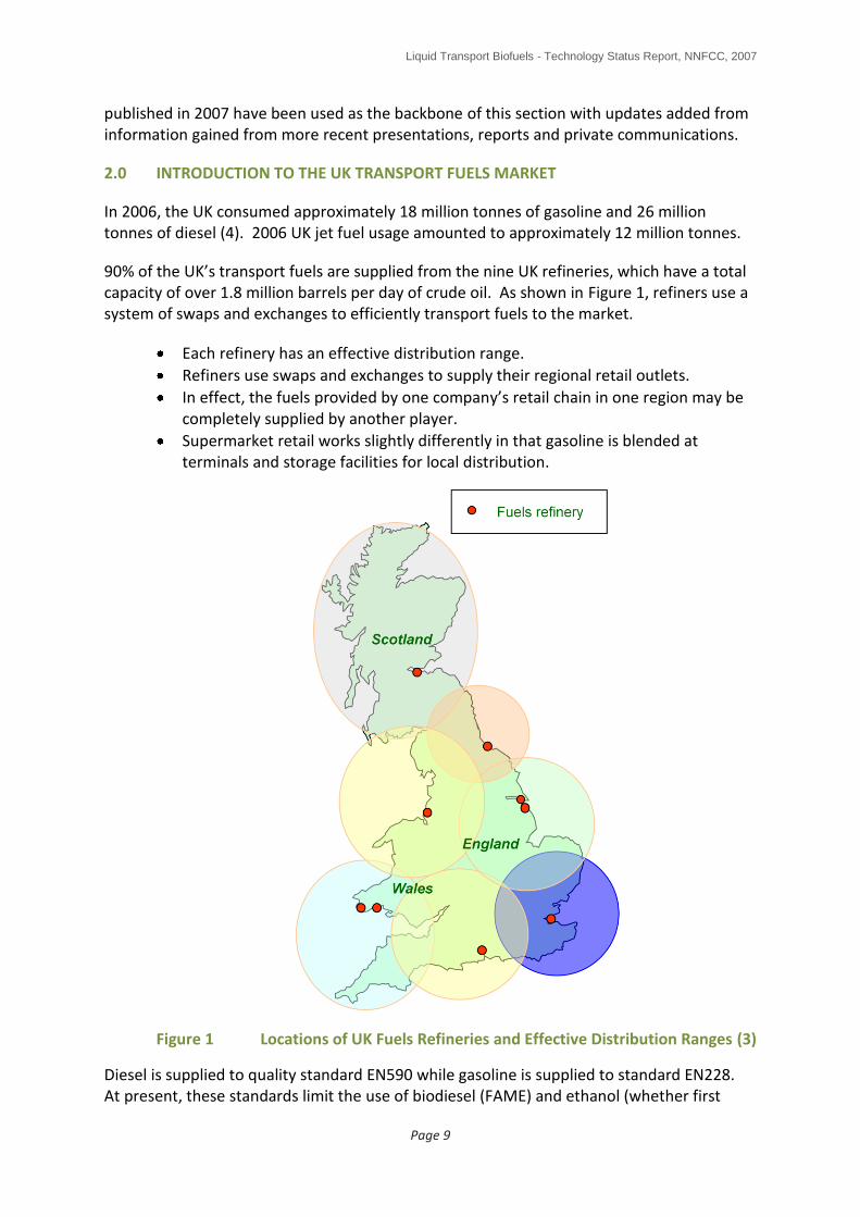
The UK refineries are configured to meet a historic demand for petrol and fuel oil. As a result of the reducing demand for petrol and fuel oil, refineries produce an excess of these products and are in deficit in others, including diesel and jet fuel (Figure 2). In the immediate short term, diesel supply is likely to become shorter as UK diesel usage is growing slowly at about +0.9% per year while gasoline usage is declining slowly by about 0.5% per year (Figure 3). The situation is similar in the EU as a whole although the new accession states, which primarily use petrol for road transport, are bringing the EU situation closer to balance.
Figure 2 UK Petroleum Products Production and Demand 2006 (4)
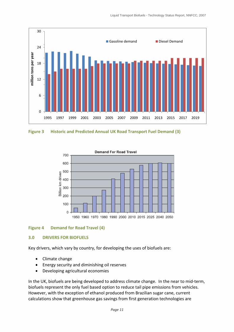
Looking to the longer term, demand for road and air travel is growing (4) (5). UK Road
transport demand is expected to rise from about 475 billion km driven per year in 2000 to
about 600 billion km/yr in 2050 (4), although growth is predicted to level out from about
2025 onwards (Figure 4). At the same time, average road vehicle efficiencies are expected
to improve (6) giving rise to the possibility that road transport fuel demand could decrease
in the long term.
Similarly, demand for air travel and hence jet fuel is growing. Demand is projected to be
between two and three times 2003 levels in 2030. Current demand is in the region of 180
million air passengers per year (mppa), rising through 276 million for 2010, 401 million for
2020 and 500 million for 2030 (7). These represent 45%, 223% and 278% increases
respectively from 2002 levels. Regarding air freight, UK demand doubled between 1989 and
1999 and is forecast to grow even more rapidly over the next 10 years (7).
0 5 10 15 20 25 30
gasoline
diesel
jet fuel
fuel oil
Petroleum gases
others
million tonnes/year
Product demand 2006 Products produced 2006
Liquid Transport Biofuels - Technology Status Report, NNFCC, 2007
Page 11
Figure 3 Historic and Predicted Annual UK Road Transport Fuel Demand (3)
Figure 4 Demand for Road Travel (4)
3.0 DRIVERS FOR BIOFUELS
Key drivers, which vary by country, for developing the uses of biofuels are:
Climate change
Energy security and diminishing oil reserves
Developing agricultural economies
In the UK, biofuels are being developed to address climate change. In the near to mid-term, biofuels represent the only fuel based option to reduce tail pipe emissions from vehicles. However, with the exception of ethanol produced from Brazilian sugar cane, current calculations show that greenhouse gas savings from first generation technologies are
0
6
12
18
24
30
1995 1997 1999 2001 2003 2005 2007 2009 2011 2013 2015 2017 2019
mill
ion
to
ns
pe
r ye
ar
Gasoline demand Diesel Demand
Liquid Transport Biofuels - Technology Status Report, NNFCC, 2007
Page 12
limited, despite potential for further optimisation; potentially higher savings can be achieved by moving to lignocellulosic technologies.
Energy security is the key driver behind the development of biofuels in China and the USA. In the USA, the demand for gasoline is about three times that of diesel which has resulted in the development of ethanol as a gasoline substitute ahead of diesel substitutes. In the EU, the demands for diesel and gasoline are roughly equal. However, in the EU and the UK, diesel demand is growing while gasoline demand is falling (the new EU states though are starting to affect this balance as they use mainly gasoline). The fact that diesel demand is growing combined with the lack of diesel production capacity across the EU and the low capital costs of FAME production plants led to the appearance of biodiesel production capacity in the UK ahead of ethanol production capacity.
The development of a biofuels industry also has the potential to improve agricultural economics by providing a potential cash crop and hence a new viable income stream for farmers. This driver is highest in the USA, followed by Brazil.
In the UK, the Renewable Transport Fuels Obligation (RTFO) will obligate refiners to include increasing levels of biofuels in the transport fuel pool, starting at 2.5% by volume in April 2008 and rising to 5% by volume in 2010/11. The 5% target is within the fuel standards but is below the 5.75% by energy target set by the EU.
4.0 BIOFUEL VOLUMES AND TECHNOLOGIES REQUIRED TO MEET UK TARGETS
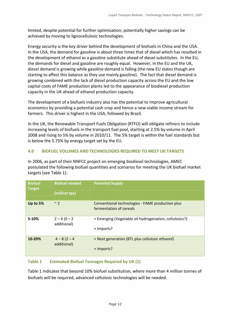
In 2006, as part of their NNFCC project on emerging biodiesel technologies, AMEC postulated the following biofuel quantities and scenarios for meeting the UK biofuel market targets (see Table 1):
Biofuel Target
Biofuel needed
(million tpy)
Potential Supply
Up to 5% ~ 2 Conventional technologies - FAME production plus fermentation of cereals
5-10% 2 – 4 (0 – 2 additional)
+ Emerging (Vegetable oil hydrogenation, cellulosics?)
+ Imports?
10-20% 4 – 8 (2 – 4 additional)
+ Next generation (BTL plus cellulosic ethanol)
+ Imports?
Table 1 Estimated Biofuel Tonnages Required by UK (1)
Table 1 indicates that beyond 10% biofuel substitution, where more than 4 million tonnes of
biofuels will be required, advanced cellulosic technologies will be needed.

Liquid Transport Biofuels - Technology Status Report, NNFCC, 2007
Page 13
The above figures and the implication that first generation technology production capacities will plateau agree with conclusions from Finnish company Neste and US company Ceres (see Figure 5 and Figure 6).
Figure 5 Biodiesel Generations - Illustrative Market Share Evolvement (8)
Figure 6 US Ethanol Production (9)
0
2
4
6
8
10
12
2006 2010 2015 2020
% o
f d
iese
l po
ol
Lignocellulosic Algae HVO FAME
0
5
10
15
20
25
30
35
40
2002 2004 2006 2008 2010 2012 2014 2016
bill
ion
s o
f U
S ga
llon
s
US Ethanol Production (Ceres)
other Energy crops Ag resids corn starch

Liquid Transport Biofuels - Technology Status Report, NNFCC, 2007
Page 14
5.0 TECHNOLOGY ASSESSMENT - CURRENT BIOFUELS AND PRODUCTION IN THE UK
There are currently four types of biofuels used for road transport in the UK:
Pure plant oil (straight vegetable oil)
Biogas (produced by anaerobic digestion)
Biodiesel (fatty acid methyl ester , FAME)
Bioethanol
The first two will not be covered in this report as they are niche products, not suitable for use via the existing infrastructure without modification.
The use of pure plant oil provides the potential for excellent greenhouse gas savings. However, use in the general transport fuel pool is limited for a number of reasons. These include:
Pure plant oil cannot be blended with crude oil derived diesel.
Vehicles must be modified to permit startup and shutdown on standard diesel, switching to using pure plant oil once the engine and fuelling system are ready – this suits vehicles which are operated for long periods of time (eg 8 hour shifts) such as buses and trucks.
Similarly, the use of biogas also provides the potential for excellent greenhouse gas savings. Use in the general transport fuel pool is again limited by a number of reasons including:
A separate and wholly new gas refueling infrastructure would be required unless the gas can be distributed via the existing gas supply network.
Purpose-built vehicles would be required (although such vehicles are becoming available, eg VW and Mercedes Benz).
5.1 First Generation Biodiesel - FAME
The FAME process for producing biodiesel from vegetable oils and waste vegetable oils is relatively mature in the UK and the EU. Current UK capacity is 400-500 thousand tonnes per year (approximately equal to 2.5% of the UK’s road diesel consumption) although actual production rates are known to be below this as a result of deteriorating margins caused by high feedstock prices and the effects of the US “splash and dash” system which is resulting in cheap US biodiesel entering the EU market at sale prices below EU production costs. Under consideration and in planning for the UK is an additional 1 million tonnes of capacity.
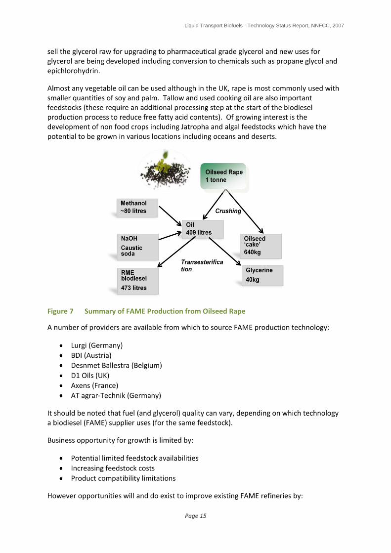
The FAME process converts vegetable oil into a diesel substitute that can be blended directly into the existing diesel infrastructure, albeit with limitations. It is produced by reacting vegetable oil with an alcohol (typically methanol is used) in the presence of a potassium hydroxide or sodium hydroxide catalyst (see Figure 7). The methanol used is usually derived from natural gas although it can fairly easily be derived from coal, in which case, the biodiesel process greenhouse gas savings will be significantly eroded. The transesterification reaction removes the glycerol molecule from the vegetable oil leaving three long chain hydrocarbons which can be used as diesel. The glycerol byproduct remaining is contaminated with excess methanol and spent catalyst. Most UK companies
Liquid Transport Biofuels - Technology Status Report, NNFCC, 2007
Page 15
sell the glycerol raw for upgrading to pharmaceutical grade glycerol and new uses for glycerol are being developed including conversion to chemicals such as propane glycol and epichlorohydrin.
Almost any vegetable oil can be used although in the UK, rape is most commonly used with smaller quantities of soy and palm. Tallow and used cooking oil are also important feedstocks (these require an additional processing step at the start of the biodiesel production process to reduce free fatty acid contents). Of growing interest is the development of non food crops including Jatropha and algal feedstocks which have the potential to be grown in various locations including oceans and deserts.
Figure 7 Summary of FAME Production from Oilseed Rape
A number of providers are available from which to source FAME production technology:
Lurgi (Germany)
BDI (Austria)
Desnmet Ballestra (Belgium)
D1 Oils (UK)
Axens (France)
AT agrar-Technik (Germany)
It should be noted that fuel (and glycerol) quality can vary, depending on which technology a biodiesel (FAME) supplier uses (for the same feedstock).
Business opportunity for growth is limited by:
Potential limited feedstock availabilities
Increasing feedstock costs
Product compatibility limitations
However opportunities will and do exist to improve existing FAME refineries by:

Liquid Transport Biofuels - Technology Status Report, NNFCC, 2007
Page 16
1. incorporating new process developments (see below) 2. incorporating technologies to improve the overall process green house gas savings;
for example by installing a biomass fired boiler thereby backing out the use of say natural gas for process energy needs.
5.1.1 Fuel Quality
A detailed comparison between FAME biodiesel with other biofuels and petrochemical derived fuels is given in the table in Appendix 2. Figure 8 shows a qualitative assessment.
Although the biodiesel specification for FAME (EN14214) has done much to improve the biodiesel quality on the market, consistency remains an issue. Variations occur due to type of refinery used, type of feedstock used, stability in storage and levels of ash content produced on combustion containing elements such as silicon, sodium, phosphorous and potassium. Such variations can lead to significant engine wear.
Freshly prepared biodiesel will undergo oxidative degradation by contact with air and metal surfaces. Highly oxidised species (aldehydes, ketones, acids) are formed as well as polymeric material (gums). These can cause poor combustion and engine wear. Different vegetable oil feedstocks produce biodiesel with different oxidation stabilities. Biodiesel stability is greatly increased by addition of antioxidants and it is critical that these are added as early as possible.
Figure 8 Qualitative summary of FAME Biodiesel

Liquid Transport Biofuels - Technology Status Report, NNFCC, 2007
Page 17
5.1.2 SWOT Analysis of First Generation Biodiesel (FAME) (1)
FAME
Strengths
Simple process with low capital cost plant
High volumetric conversion to diesel product
Commercial plant operating experience
Increasing commercial plant size as technology matures through experienced technology providers
Can convert waste oils and fats to transport fuels.
Liquid biofuels used in low percentage blends do not require use of new refueling infrastructure.
Weaknesses
Biodiesel quality consistency issues
Limited feedstock supply, in particular to meet future biodiesel targets
Competition with food production for land
Increasing feedstock costs, which has a large impact on production cost
Potentially low value by-products (glycerol)
Some waste streams, including spent catalyst
Environmental benefits lower than other biodiesel process routes
Methanol needed as a co-feed
Opportunities
Improved processes under development which may help to reduce production costs
New process developments to convert by-product glycerine into more valuable product
Threats
Increasing feedstock competition with alternative processes such as vegetable oil hydrogenation
Increasing competition with food for land
High feedstock costs and possibly oversupply of by-product glycerine will significantly increase production cost (although glycerol prices in early 2008 are very attractive)
Environmental risks from land conversion for biofuel development
5.1.3 FAME Process Developments
There is now a move away from the early small “cottage industry” plants towards large-scale production. Plant sizes are increasing from 10-40,000 tpy up to 200-250,000 tpy. Such plants are becoming viable as a result of ongoing development by the more experienced technology providers and are necessary to drive down production costs. Ability to process a wide range of potential vegetable oils is becoming an increasingly important factor in technology development.
Leading biodiesel technology providers are Lurgi (Germany) and BDI (Austria). Both companies have been developing biodiesel technology since the early 1990’s. Currently, there is a growing number of larger-scale plants (up to 200 - 250,000 tpy), either operational or planned, throughout Europe (see Appendix 1), including the UK although many plans are currently stalled because of the “splash and dash” issue. Other recent technology providers with large-scale facilities in Europe include Desmet Ballestra (Belgium), Axens (France), and
Liquid Transport Biofuels - Technology Status Report, NNFCC, 2007
Page 18
AT Agrar-Technik (Germany). INEOS have announced a 500,000 tpy (~12,000 barrels/day) biodiesel development at their Grangemouth refinery, UK, due to be operational by 2008 (ICIS Chemical Business 2006 and 2007). INEOS aim to have 1.2 million tpy biodiesel production in Europe by 2010, equivalent to about 6.5% of UK road transport diesel consumption.
5.1.4 Advanced processes
There are a number of emerging FAME technologies under development, such as co-solvent processes (eg BiOx), heterogeneous catalysis (eg Axens Esterfip-H, see Bloch 2006 (10)), enzymatic conversion of triglycerides or FFA’s, and in-situ conversion of oil in seeds (eg Petronas).
Axens (a wholly owned subsidiary of the IFP) have installed Esterfip-H units at Sete in France (2006) and Perstorp in Sweden (Q1 2007). A further six are under construction (11).
In the UK, TMO Biotech in Surrey has developed a process for transesterifying vegetable oil with methanol in the presence of a microbial organism. The result is a much cleaner glycerol by-product which requires less energy to upgrade for other uses.
Also in the UK, Quicksilver has developed, in collaboration with the Centre for Process Engineering, a proprietary biodiesel technology (12) which is claimed to:
reduce reactor volumes and hence capital cost
reduce methanol consumption by a factor of two, thereby reducing methanol recycling requirements
reduce production time (from 20 hours down to less than one)
permit improved quality control and reliability
achieve reduced loss of biodiesel (FAME) into the waste stream compared to comparable processes
have a high tolerance of feedstock variability with a flexible pretreatment step
have a lower energy consumption compared to comparable processes.
This process has been evaluated and validated at lab scale at present. Options for commercialisation include retrofitting to existing operational units and erecting new production facilities. Retrofitting existing facilities offers the potential for increasing capacity, increasing product quality and yield and a reduction in specific energy demand.
5.1.5 Glycerine by-product
By-product glycerine quantity and quality has always been an issue when using low cost feedstocks. Impurities tend to concentrate in the glycerine, reducing quality. In the recent past, markets for crude glycerine became oversupplied as FAME production increased. Some new developments for alternative uses for glycerine recently announced include:
UOP are developing a catalyst that can convert the glycerol generated from the conventional biodiesel route into propylene glycol.
Researchers at Poland’s Wroclaw Agricultural University claim to have developed a yeast strain to convert crude glycerine derived from biodiesel production into citric acid on an industrial scale.

Liquid Transport Biofuels - Technology Status Report, NNFCC, 2007
Page 19
There is also continued interest in using glycerine as a potential feedstock for high value products such as 1,3 propanediol (PDO).
BMCN in the Netherlands have converted the Methanor plant to convert glycerol into methanol (500,000 tpa rising to 1 million tpa) from Q1 2008.
Use of glycerine as an accelerator in anaerobic digestion plants.
5.2 First Generation Bioethanol
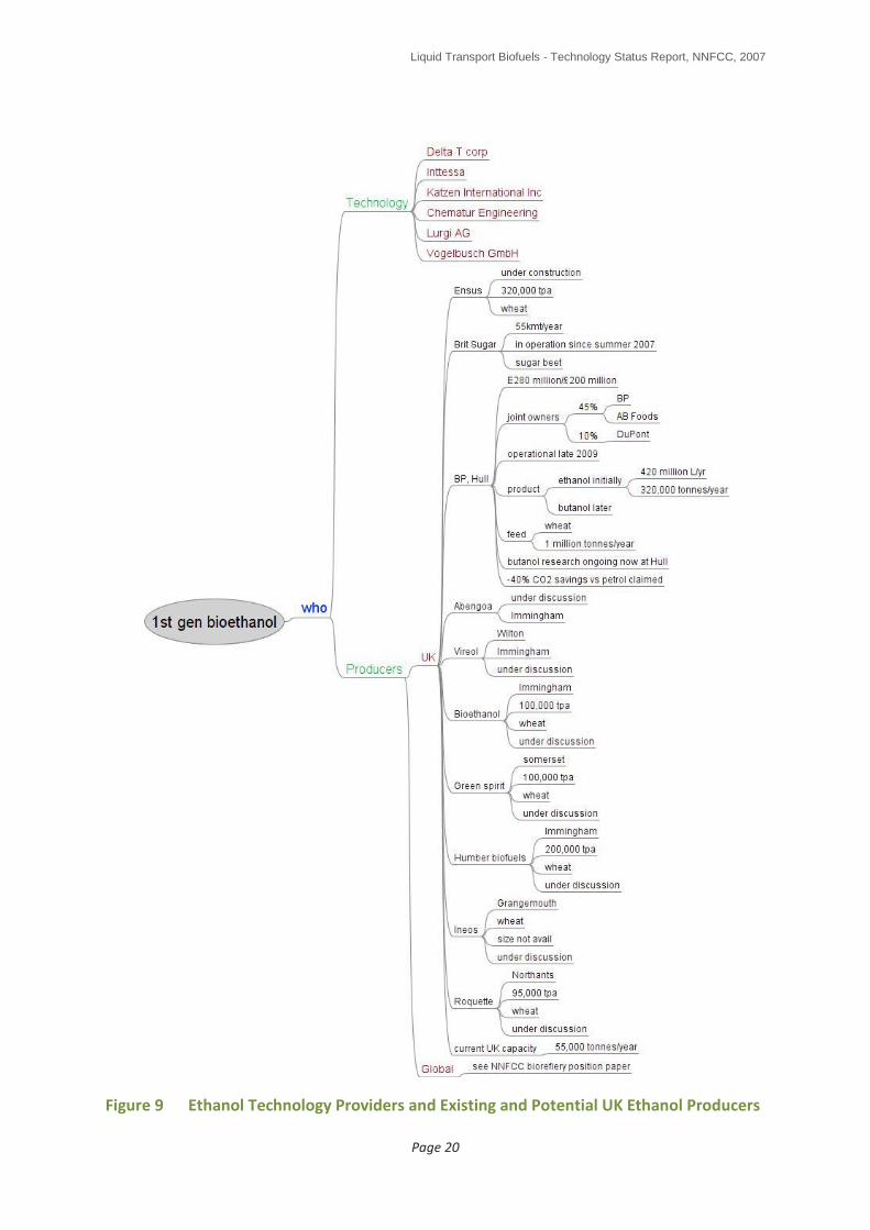
First generation ethanol production is emerging in the UK in 2007 with just one plant operational from September 2007 (British Sugar, Wissington) (13). This plant has a capacity of 55,000 tonnes/year of ethanol made from molasses, a byproduct from the production of sugar from sugar beet.
A second plant is currently under construction in Wilton on Teesside (Ensus) and a number are in planning including the BP/British Sugar/Dupont plant planned for Saltend and due to start operating from Q4 2009 (13).
A full list of the plants in operation, under construction and in planning is shown Figure 9 and in the NNFCC Biorefineries Position Paper (14). In terms of the technology suppliers, only a few, at present, have experience of using wheat as a feedstock (eg Abengoa Voegelbusch and Intessa).
Ethanol for fuel use is made in the same way as ethanol for beverage use. For fuel use though, a high purity product is required, either for gasoline blending or chemical conversion into ethyl tertiary butyl ether (ETBE) or other chemicals such as ethyl acetate.
A number of starch or sugar based feedstocks can be used to produce ethanol including cereals such as wheat, rye and barley, corn, sugar cane, sugar beet, sweet sorghum and excess wine. For the UK situation, wheat is expected to be the primary feedstock.
In a typical modern bioethanol facility, a combination of physical/mechanical and chemical processing is used. Plants can either be “dry milling” or “wet milling”. In Europe, most plants use the relatively straight forward dry milling process which produces ethanol with a byproduct called distillers dry grains and solubles (DDGS), a high protein material which can be used as an animal feedstock or as a fuel.
Wet milling processes are often combined with corn syrup production units. Such processes produce byproducts which include gluten meal and corn oil amongst others. Owners can choose to either produce ethanol or high fructose corn syrup depending on the prevailing economics – such plants are typical of large scale US bioethanol and foodstuff producers such as Archer Daniels Midland (ADM) and Cargill.
The overall process is summarised in Figure 10. Grain is firstly ground into granules slightly larger than wholegrain flour. The ground grain is then mixed with water to make a “flour” slurry or “mash” and treated with enzymes to convert the starches in the grain to sugar (glucose). The glucose is then fermented using yeast to a “beer” which is a 10% solution of ethanol in water. The yeast and proteins from the grain form the DDGS byproduct which is dried to make a high protein animal feed.
Liquid Transport Biofuels - Technology Status Report, NNFCC, 2007
Page 20
Figure 9 Ethanol Technology Providers and Existing and Potential UK Ethanol Producers

Liquid Transport Biofuels - Technology Status Report, NNFCC, 2007
Page 21
Figure 10 Summary of First Generation Bioethanol Production
The ethanol “beer” must be purified by distillation until the azeotrope is reached (a constant boiling mixture of 95.6% by mass ethanol in water). Azeotropic distillation with molecular sieves (in the latest technology) is used to produce anhydrous fuel ethanol (note that anhydrous ethanol is not required if the ethanol fuel is to be used as E100). Further processing may be used to remove higher alcohols and other impurities if needed. For fuel use, the higher alcohols can be left in along with a denaturant.
There are a significant number of plants in the USA producing ethanol from corn including a number of “mega” plants of greater than 500 million litres per day. Corn is a simpler feedstock to convert than wheat. The use of wheat results in higher yields of DDGS with correspondingly lower yields of ethanol thereby changing the mechanical and material flowrates (hydrodynamics) of the process plant. Hydrodynamic volumes for wheat are greater than for corn leading to the risk of not achieving design throughput, rather than a complete failure.
First generation processes, therefore, operate commercially using mainly agricultural grains producing ethanol at scales between 50,000 and 250,000 tonnes/year. The technology has been designed and implemented with corn at much larger scales, but moving to a mainly wheat based feedstock for the EU situation will bring added challenges (15).
5.2.1 Fuel Quality
A detailed comparison between ethanol with other biofuels and petrochemical derived fuels is given in the table in Appendix 2. Figure 11 shows a qualitative assessment.

Liquid Transport Biofuels - Technology Status Report, NNFCC, 2007
Page 22
Compared with gasoline, ethanol is a pure compound rather than a mix of many. As noted above, for fuel use it must be supplied as anhydrous ethanol else there is the potential for the gasoline/ethanol mixture to separate.
There are a number of issues which must be addressed when considering blending ethanol into gasoline including (16):
Vapour pressure – ethanol boils at a lower temperature than gasoline. This has an effect on engine cold starting but is only really an issue at high blends such as E85. Vapour pressure must also be taken into account when designing storage tanks, pumps and pipelines (especially is using existing facilities designed for other fuels). It also leads to an increase in volatile organic compound emissions (VOC’s).
Miscibility with water – ethanol is hydrophilic. It cannot be transported through existing pipelines with gasoline and must be splash blended at the last point in the supply chain prior to the forecourt. In Minnesota in the USA, within state deliveries from the CVC ethanol plant are made by truck while out of state exports are made by train.
Energy density – ethanol contains about 61% of the energy of gasoline by mass. At low blending rates, ethanol improves vehicle engine efficiency as it acts as an oxygenate. However, at high blending rates, energy density affects driving range (ie mpg) as if affects the volume and weight of fuel contained in the fuel tank.
Octane rating – ethanol has a higher octane rating (1081) compared to gasoline (typically 90-1001). The use of a higher octane fuel permits the engine designer to use higher compression ratios and hence achieve higher engine power outputs for a given engine.
Solvent – ethanol is a solvent. Vehicle designers need to take this into account when selecting fuel system seals.
1 Research Octane Number (RON)

Liquid Transport Biofuels - Technology Status Report, NNFCC, 2007
Page 23
Figure 11 Qualitative Summary of Ethanol
Liquid Transport Biofuels - Technology Status Report, NNFCC, 2007
Page 24
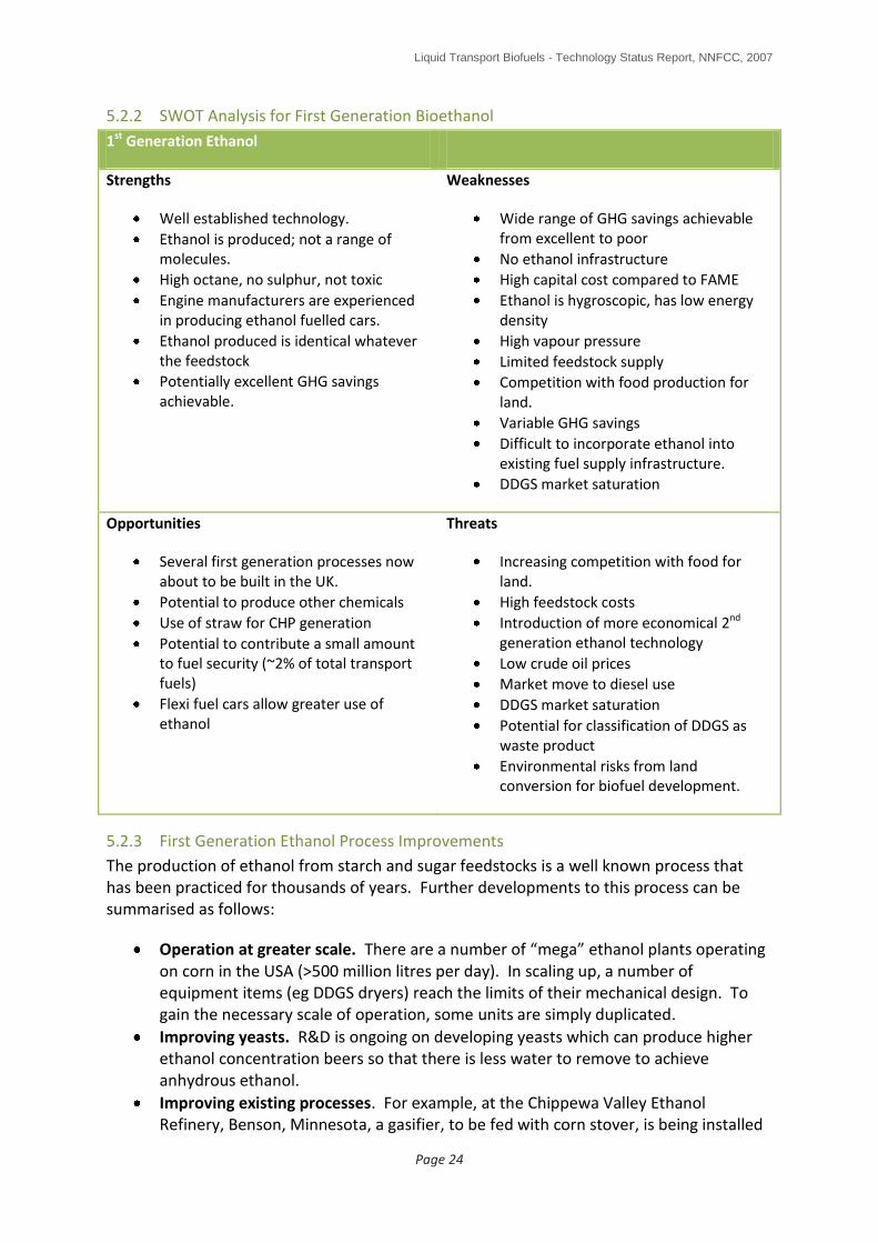
5.2.2 SWOT Analysis for First Generation Bioethanol
1st Generation Ethanol
Strengths
Well established technology.
Ethanol is produced; not a range of molecules.
High octane, no sulphur, not toxic
Engine manufacturers are experienced in producing ethanol fuelled cars.
Ethanol produced is identical whatever the feedstock
Potentially excellent GHG savings achievable.
Weaknesses
Wide range of GHG savings achievable from excellent to poor
No ethanol infrastructure
High capital cost compared to FAME
Ethanol is hygroscopic, has low energy density
High vapour pressure
Limited feedstock supply
Competition with food production for land.
Variable GHG savings
Difficult to incorporate ethanol into existing fuel supply infrastructure.
DDGS market saturation
Opportunities
Several first generation processes now about to be built in the UK.
Potential to produce other chemicals
Use of straw for CHP generation
Potential to contribute a small amount to fuel security (~2% of total transport fuels)
Flexi fuel cars allow greater use of ethanol
Threats
Increasing competition with food for land.
High feedstock costs
Introduction of more economical 2nd generation ethanol technology
Low crude oil prices
Market move to diesel use
DDGS market saturation
Potential for classification of DDGS as waste product
Environmental risks from land conversion for biofuel development.
5.2.3 First Generation Ethanol Process Improvements
The production of ethanol from starch and sugar feedstocks is a well known process that has been practiced for thousands of years. Further developments to this process can be summarised as follows:
Operation at greater scale. There are a number of “mega” ethanol plants operating on corn in the USA (>500 million litres per day). In scaling up, a number of equipment items (eg DDGS dryers) reach the limits of their mechanical design. To gain the necessary scale of operation, some units are simply duplicated.
Improving yeasts. R&D is ongoing on developing yeasts which can produce higher ethanol concentration beers so that there is less water to remove to achieve anhydrous ethanol.
Improving existing processes. For example, at the Chippewa Valley Ethanol Refinery, Benson, Minnesota, a gasifier, to be fed with corn stover, is being installed
Liquid Transport Biofuels - Technology Status Report, NNFCC, 2007
Page 25
to make producer gas which is to be used in place of natural gas to raise steam for ethanol distillation and DDGS drying. This addition is estimated to increase the product ethanol green house gas savings from -25% to about -55%, although the investment was justified on the grounds of economics (a 3-4 year payback was quoted).
Developing lignocellulosic ethanol processes. Most focus on improving the actual ethanol production process is in this area with much work being carried out in the USA.
Biorefinery development. In the same way as oil refineries have been modified and added to in a stepwise fashion since they were built, there is the potential for existing first generation ethanol refineries to be improved and added to. In the example of the Chippewa Valley refinery above, a new gasifier is already being added. Future developments could perhaps make use of the TMO Biotech process (see below) to extract additional ethanol from the DDGS byproduct and/or the addition of a lignocellulosic ethanol production facility running in parallel with the existing first generation process. Combining a first generation process train with a second, lignocellulosic process train is being employed by both Abengoa and Poet in the development of their cellulose-to-ethanol demonstration facilities in the USA. It offers a number of potential advantages including the ability to reduce energy requirements through process integration and the potential for reducing capital investment costs by using existing process plant (but expanded) such as ethanol distillation units, storage tanks and DDGS dryers.

Liquid Transport Biofuels - Technology Status Report, NNFCC, 2007
Page 26
6.0 TECHNOLOGY ASSESSMENT - EMERGING TECHNOLOGIES
6.1 Biochemical (Fermentation) Based Processes
There are two emerging technologies which use fermentation as their base process:
Ethanol produced from lignocellulosic materials
Butanol (produced from starch/sugar feedstocks – note that butanol works as a diesel vector also (17)).
In addition, there is work ongoing developing a new fuel substitute called furanics – a short review of this work has been included at the end of this section.
Of these, most work around the world is focused on the lignocellulosic ethanol route.
6.1.1 Lignocellulosic Ethanol
The limited availability of conventional feedstocks for first generation bioethanol production have resulted in a high level of research funding into ethanol production from biomass over the last 25 years. In the United States for example, the DoE have provided a grant total of $385 million to drive lignocellulosic ethanol development. Under this framework, six companies are planning to build plants.
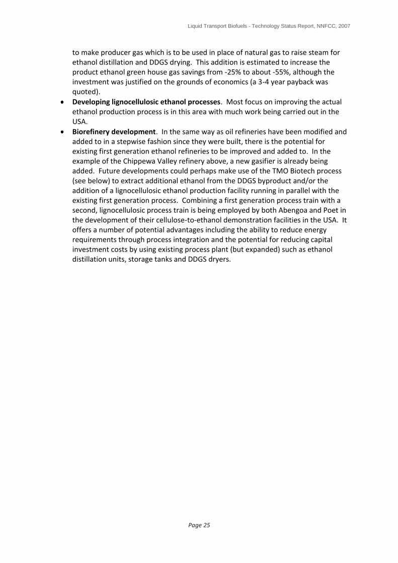
Plant biomass contains approximately 75% polysaccharides, a rich source of sugars. Production of ethanol (which is no different from that produced from first generation processes) from this biomass by fermentation is, however, significantly more complicated than its production from first generation feedstocks such as sugarcane/beet and starch crops such as wheat grain. The process can be divided into three phases: pretreatment of biomass to unmask the contained carbohydrate polymers, hydrolysis of carbohydrate polymers to sugar monomers and finally fermentation of sugars to ethanol (see Figure 12). The final stages of distillation and final drying to produce anhydrous ethanol are technically the same as for first generation processes and so are not covered any further in this report. Various technologies, especially for pretreatment, are being investigated. Pretreatment of biomass is technically challenging and forms a large part of the process cost and therefore will need to be optimised prior to commercialisation. Due to the different types of carbohydrates contained in biomass, a package of enzymes/microbes will be required for hydrolysis and fermentation; this package is a significant process cost and requires optimisation.

Liquid Transport Biofuels - Technology Status Report, NNFCC, 2007
Page 27
Figure 12 Schematic of the Current Lignocellulosic Bioethanol Process (2)
6.1.1.1 Feedstocks
A wide range of biomass feedstocks are suitable for converting to ethanol including:
agricultural wastes such as wheat, barley and rape straws
wood such as forest thinning, waste woods and short rotation coppice (SRC)
energy crops such as miscanthus and switchgrass
biological municipal solid wastes
6.1.1.2 Feedstock Size Reduction (2)
The first stage in the production of ethanol from biomass is cleaning followed by chipping or milling to reduce its size. Size reduction is necessary to provide a pumpable slurry and to increase the biomass surface area so that mass transfer effects are minimised during the downstream processes. Techniques for size reduction include hammer, disk and knife milling and are well established. This step is considerably more involved than that utilised in conventional grain milling. Depending on the biomass feedstock used, the milling step can add considerable cost to the overall bioethanol production cost due to its energy intensity. Some pretreatment techniques claim not to require biomass size reduction.
6.1.1.3 Feedstock Pre-treatment (2)
The purpose of the pretreatment step is to further increase the surface area of the lignocellulosic material, disrupt the structure of the lignocellulose such that the cellulose

Liquid Transport Biofuels - Technology Status Report, NNFCC, 2007
Page 28
component is accessible to hydrolysing agents and reduce the crystallinity of the cellulose to further facilitate hydrolysis (Figure 13). Depending on the nature of the pretreatment technology selected, this step can also include solubilisation of the lignin or the hemicellulose component. Due to the recalcitrance of the lignocellulose structure these treatments are generally severe in nature and are combinations of either physical, chemical, biochemical or thermal treatments. Consequently, the pretreatment process represents a significant cost element of the whole lignocellulosic bioethanol process.
Figure 13 Introduction to Biomass Pretreatment
The performance criteria for an optimum pretreatment technology are:
Maximise the yield of both glucose and pentose sugars in downstream processing operations
Facilitate the recovery of lignin for valorisation
Minimise the degradation of sugars into chemicals that inhibit downstream enzymatic processing such as furfural and hydroxymethyl furfurals.
Be flexible with regard to the nature of lignocellulosic feedstock
Does not require expensive biomass size reduction (milling) before pretreatment
Utilise low cost chemicals and minimise waste production

Liquid Transport Biofuels - Technology Status Report, NNFCC, 2007
Page 29
Has low energy requirements and low capital intensity
The pretreatment processes considered to be the most advanced are:
Acid Pretreatments: The use of acids to pre-treat biomass and to hydrolyse the resultant hemicellulose and cellulose sugars has been known for many years and was a central part of early chemicals manufacture from wood – this is the technology being used by Royal Nedalco in the Netherlands as they develop their own lignocellulosic ethanol technology. More recently, both dilute and concentrated acid biomass pretreatment technologies have been developed for bioethanol production. Of these the most well known is the NREL dilute sulphuric acid process. This process operates at 180-200°C with a residence time of around 1 minute. The hemicellulose fraction is hydrolysed into pentose sugars and the downstream hydrolysis of the cellulose is improved.
The use of dilute acid requires high temperatures which can degrade the sugars into chemicals such as furfurals. Not only does this reduce the yield of fermentable sugars but such degradation products are toxic to downstream fermentation microorganisms. To circumvent this, the process can be staged at two temperatures: a lower temperature to remove the more easily hydrolysed hemicellulose components followed by a higher temperature treatment to hydrolyse the remaining hemicellulose component. This ensures that the majority of the hemicellulose derived pentose sugars are not exposed to unnecessary high temperatures and thereby maximises the sugar yield. An alternative is to run a counter-current reactor which ensures that hemicellulose sugars once formed flow directly out of the reactor. Furthermore, studies have shown that a pressurised hot water wash directly after the pretreatment process improves the overall process by removing soluble lignin species and degradation products which may hinder downstream processing.
As discussed, the disadvantage of the dilute acid pretreatment process is its propensity to produce sugar degradation products that are toxic to downstream fermentation microorganisms. Attempts to remove these inhibitors after the pretreatment step, invariably lead to reduction in the sugar yields. Additionally, the dilute acid process requires expensive reactor construction materials and a downstream acid neutralisation unit which adds capital cost. Acid neutralisation is usually performed with calcium hydroxide which creates a waste disposal issue with the resultant gypsum.
Groups in Sweden have also been active in the development of dilute acid pretreatment processes for many years. Sekab in collaboration with a number of Swedish Universities are developing wood cellulose bioethanol processes that can be integrated with existing pulp manufacture. This consortium operates a 400 litre per day bioethanol plant utilising dilute acid pretreatment technology.
A pretreatment process utilising concentrated sulphuric acid has also been developed in parallel. The concentrated acid process has the benefit of being able to operate at much lower temperatures and thereby reducing the formation rate of sugar degradation products. The concentrated acid pretreatment hydrolyses both the hemicellulose and the cellulose components of the biomass. If this process is to be economic the concentrated acid must be recovered and recycled, usually by ion exchange resins. As with the dilute acid route, downstream neutralisation also produces a gypsum waste disposal issue.

Liquid Transport Biofuels - Technology Status Report, NNFCC, 2007
Page 30
Arkenol, Losonoco and Masada have developed concentrated acid biomass pretreatment processes, all reportedly close to commercialisation. Both Losonoco and Masada plan to utilise their technology on municipal solid waste feedstock.
Steam Explosion Techniques: Steam explosion is a well known biomass pretreatment process having been used for many years in the production of fibreboard – this may be the type of process being used by Biogasol in Denmark who are planning to have a demonstration plant producing ethanol in 2008. Steam explosion entails subjecting the lignocellulosic material to high pressure steam at 20-50 bar pressure and 160-260°C temperature for a few minutes before rapidly decompressing back to atmospheric pressure. The subsequent explosion greatly increases the surface area of the biomass material and increases the rate of hydrolysis of the treated cellulose in downstream processing. The beneficial effect of steam explosion are reported to depend on the nature of the biomass feedstock and are considered very effective for hardwoods but not for softwoods. Chemical reactions occur during steam explosion and the hemicellulose fraction is partly hydrolysed to produce oligomers, sugars and degradation products. A water wash is required to remove the degradation products from the pretreated biomass prior to downstream processing. Such washing, however, leads to loss of solubilised sugars, and the yield of xylose sugars is reported to be only 45-65% using steam explosion. Steam explosion is an autohydrolysis process and can produce inhibitory by-products such as furfurals, organic acids and phenolic derivatives. The most efficient means to deal with these compounds is either to perform a water wash on the pretreated material or neutralise it with calcium hydroxide. Addition of dilute sulphuric acid to the steam explosion process is reported to be beneficial in increasing pentose sugar yields to around 70%.
SunOpta, a Canadian based engineering group, has developed a continuous steam explosion process which will be utilised in the Abengoa bioethanol demonstration plant in Spain. SunOpta (previously Stake Technology) have supplied a steam explosion pilot plant to the ENEA Research Facility in Southern Italy. Iogen has developed its own acid-catalysed steam explosion pretreatment technology for its straw to bioethanol process.
Liquid Hot Water: An alternative autohydrolysis technique to steam explosion is to expose the lignocellulosic material to superheated water (180 – 230°C) maintained in the liquid state by high pressure. Liquid hot water treatment is reported to need little particle size reduction before treatment. This treatment completely dissolves the hemicellulose fraction and renders the cellulose fraction highly receptive to enzymatic hydrolysis. The process liberates organic acids, such as acetic acid, from the biomass which catalyse further hydrolysis. As with steam explosion, sugar degradation products are formed which are toxic to downstream fermentation microorganisms. A number of different process configurations have been developed to maximise sugar yields and beneficial operation has been demonstrated by controlling the pH of the process by adding potassium hydroxide. This process is still at the development stage.
Ammonia Fibre Explosion Pretreatment (AFEX): This process is similar to that of steam explosion in that the lignocellulosic material is exposed to liquid ammonia at high temperature and pressure and then the pressure is rapidly reduced. The ammonia is heated to 90°C and the residence time is around 30 minutes. In contrast to steam explosion, the hemicellulose fraction is not significantly solubilised to monomeric sugars and the

Liquid Transport Biofuels - Technology Status Report, NNFCC, 2007
Page 31
composition of the solid remains the same after pretreatment. The AFEX treatment results in the rupture of the lignin-hemicellulose bonds and some hydrolysis of the hemicellulose to produce oligomers. There is also greatly reduced production of furfural and hydroxymethylfurfural compared to other pretreatments but some organic acids are liberated which are toxic to downstream fermentation microorganisms. Ultimate sugar yields are high using AFEX. The disadvantage of AFEX is the need to capture and recycle the ammonia which adds significant cost to the overall capital of the pretreatment process. This process has been under development for over 20 years and is pioneered by Bruce Dale at Michigan State University.
Alkali Pretreatment Process: Alkali treatments involving hydrolysis with ammonia, calcium, sodium or potassium hydroxide are similar in nature to the Kraft process in that the lignin component of the biomass is dissolved. Most activity is concentrated on the lime pretreatment technology being developed by Holtzapple at Texas A&M University. The digestibility of the lignin depends on the severity of the process conditions used and the nature of the biomass feedstock. The residual hemicellulose and cellulose can then be hydrolysed and fermented downstream. Lime is generally the alkali used due to its lower cost and the fact that it can be readily precipitated out from solution after treatment. In contrast to acid based pretreatments, reaction temperatures are low and residence times tend to be of the order of hours rather than minutes.
Others: Other pretreatment processes still at the development stage include the use of:
organic solvents to fractionate the lignocellulose into different streams for upgrading. Examples of such process developments include the Lignol Process which uses ethanol to solubilise the biomass and the ACOS process which utilises acetone as the solvent. Both of these processes offer potentially high yields of sugars and in contrast to the pretreatment technologies described above produce a unique refined lignin byproduct which could have market value above that of its energy value.
Fungal (enzymatic) pre-treatments using, for example, brown, white and soft-rot fungi. These enzymes have the advantage of having low energy requirements and mild processing conditions.
Pretreatment Summary: The benefits of the respective pretreatment technologies are summarised in Table 2.
It is clear that there are a large number of biomass pretreatment technologies at varying stages of development but no obvious winners at this stage. Each individual pretreatment technology has its own strengths and weaknesses. It is also apparent that there is no universal biomass pretreatment system and each process technology has beneficial attributes for certain feedstocks. For instance, the concentrated acid process is most suitable for the pretreatment of municipal solid wastes.
One of the issues with the development of improved biomass pretreatment processes is a lack of the fundamental understanding of some of the chemistry and kinetics involved. Another issue affecting selection of the most appropriate technology is the lack of rigorous comparative data on each system. To address these issues the USDA and latterly the DOE

Liquid Transport Biofuels - Technology Status Report, NNFCC, 2007
Page 32
have funded a consortium activity, entitled CAFI, which brought together the leading US exponents of each pretreatment technology to develop robust comparative data and a better fundamental understanding of each process when applied to a specific feedstock. The biomass feedstock chosen for the first part of the activity was corn stover.
Pretreatment process
Reduced inhibitor
production
High yield of fermentable
sugars
Chemical recycling
Waste disposal
Investment cost
Dilute acid
Concentrated acid
Steam explosion
AFEX
Solvents
Lime treatment
Table 2 Qualitative Evaluation of Selected Pretreatment Technologies (2)
The closest pretreatment technologies to commercialisation appear to be the dilute acid, concentrated acid and the steam explosion processes being used, for example, by Royal Nedalco in the Netherlands and Biogasol in Denmark (Figure 13). All of these processes represent a significant capital cost element towards the overall bioethanol production cost from lignocellulosic feedstocks. The capital cost of a dilute acid pretreatment process for a 56 million gallon bioethanol plant is of the order of $25 million. The production costs of bioethanol increase in the following order: dilute acid AFEXlime.
The greater majority of technology development in this area is occurring in the United States funded by the USDA and DOE with some activity in Canada and isolated pockets in Europe in Italy and Sweden.
The pretreatment section of the lignocellulosic process remains an area with significant potential for improvement and current processes moving forward to commercialisation are suboptimal in terms of cost and performance. The severity of the different processes reflects the recalcitrant nature of the lignocellulosic feedstocks and imparts a large capital and operational cost to the overall bioethanol process. Different biomass feedstocks are suited to different pretreatment technologies. A greater fundamental knowledge of the structure–activity relationships between the components of lignocellulose is required and a detailed understanding of the kinetics of the different reaction pathways during pretreatment is necessary before improved systems can be designed.

Liquid Transport Biofuels - Technology Status Report, NNFCC, 2007
Page 33
6.1.1.4 Cellulose Hydrolysis (2)
In the conventional first generation bioethanol process using starch crops such as wheat grain, the glucose sugars needed for fermentation are readily obtained by hydrolysing starch using low cost and active amylase enzymes. Unlike starch cellulose is not hydrolysed by conventional amylase enzymes and requires the application of either liquid acids or sophisticated cellulose enzymes to perform the conversion to sugar (saccharification) – see Figure 14.
Figure 14 Introduction to Enzymes
A biological route to cellulose hydrolysis offers significantly more potential in reducing process costs than the use of liquid acids. Enzymatic hydrolysis is preferable due to its milder operating conditions, reduced by-product formation and the non-corrosive reaction medium. Cellulose hydrolysis is the rate limiting step in bioethanol production and to be successful an enzyme catalyst (cellulase) must overcome a number of challenging barriers:
Unreactive crystalline cellulose
Presence of lignin blocking reactive sites
Low substrate surface area
Low hydrolysis rates
Substrate inhibition
Product inhibition

Liquid Transport Biofuels - Technology Status Report, NNFCC, 2007
Page 34
Improved biomass pretreatement processes may beneficially address the first three of these issues but improved cellulase systems are required to address the latter three barriers and considerable effort has been directed towards the identification and development of improved micro-organisms and enzymes for cost effective processing. Both bacteria and fungi can produce enzymes for cellulose hydrolysis but the majority of research has concentrated on aerobic fungal systems such as Trichoderma reesei. Iogen, who are close to the commercialisation of a straw based bioethanol process, have a proprietary cellulase system based upon a genetically modified T. reesei system. Due to the ability of termites to digest cellulose, many groups are active in the identification of cellulase genes present in the termite hindgut and their exploitation in designing new cellulase biocatalysts – Verenium are one company who are following this route – Figure 15 shows a process flow of the Verenium process which has separate vessels for the C5 and C6 fermentations (18).
Figure 15 Outline of Verenium Bioethanol Production Process (19)
Anaerobic bacterial systems such as Clostridium offer the potential of both cellulose hydrolysis and glucose fermentation in one step. Cellulase costs have in the past been prohibitively expensive; contributing some $5 to the production cost of each bioethanol gallon ($1.32/litre). One of the difficulties in developing new cellulases is the fact that they comprise a cocktail of different enzymes. These enzymes have specific roles within the cellulose saccharification process including the creation of free cellulose chains ends, cutting these chains to free cellobiose units (glucose dimmers) and finally hydrolysis of cellobiose to produce glucose. In 2000, the US DOE contracted both Genencor and Novozymes to genetically engineer improved cellulase enzymes and meet a target of a ten fold reduction in enzyme costs. Both programmes have delivered successful outcomes with Genencor and Novozymes each reporting 30 fold reductions in cellulase enzyme costs such that enzyme now contributes of the order of $0.1 to $0.2 to the cost of a gallon of bioethanol (NB Genencor announced on 16th November 2007 that they had introduced the first commercial enzyme to the market, under the trade name Accellerase 1000 (20)). However, further cellulose cost reductions are still required if lignocellulose bioethanol is going to be cost competitive, a realistic target for this would be an enzyme cost of $0.03/gallon. These systems were specifically designed for corn stover biomass that had been pretreated using

Liquid Transport Biofuels - Technology Status Report, NNFCC, 2007
Page 35
the dilute sulphuric acid process. New enzyme packages are likely to be needed for different biomass feedstocks and pretreatments. Recent research at VTT in Finland and Lund University (NILE project, led by IFP of France (21)) in Sweden has been concerned with the development of thermophilic cellulase enzymes that can operate at higher temperatures than conventional cellulases. Such systems offer potential benefits in increased reaction rates, higher yield and higher integration potential.
The manufacture of cellulase enzymes is now big business and many of the enzyme manufacturers (see Figure 16) are now forming strategic collaborations with key players in the developing lignocellulosic bioethanol sector:
Both Novozymes and SunOpta have formed a collaboration with a Chinese Bioethanol producer (CRAC) to develop lignocellulosic technology. Novozymes celullase enzymes will be evaluated in the Abengoa bioethanol plant. Novozymes also supply enzymes to Cofco of China, CTC of Brazil and POET (formerly Broin of USA).
Diversa have entered into collaboration with Syngenta to develop novel enzymes for lignocellulosic bioethanol and have also formed a collaboration with Celunol.
Dyadic International, a genomics company who have a proprietary fungal strain has formed collaborations with both Royal Nedalco to develop enzyme systems for utilising wheat bran and with Abengoa to develop novel enzymes for utilising straw.
Shell have just announced (6th November 2007) that it is to buy a stake in the US biotechnology company Codexis to develop new enzymes for the production of biofuels (22). Under their investment plans, Shell plan to use the new enzymes to build a commercial lignocellulosic facility within the next five years.
6.1.1.5 Fermentation of C5 (Pentose) and C6 Sugars (2)
The efficient fermentation of all the sugars streams released from the pretreatment and hydrolysis steps is a prerequisite for economic conversion of biomass to bioethanol. However, conventional bioethanol yeasts such as Saccharomyces cerevisiae and Zymomonas mobilis, (a bacteria with potential for bioethanol production) cannot ferment the pentose sugars released from the hemicellulose fraction. This has represented a considerable barrier to the commercialisation of lignocellulosic bioethanol production. More than twenty years research has been directed towards the development of improved micro-organisms for the fermentation of the pentose sugars. For cost effective processing, such organisms must be able to co-ferment both glucose and pentose sugar (which include arabinose and xylose sugars) streams. Recent advances in metabolic engineering have led to a spate of proprietary micro-organisms for xylose fermentation. Considerable effort has been directed towards the genetic engineering of the bacteria E.coli and Z.mobilis to selectively introduce pathways for the fermentation of arabinose and xylose sugars to bioethanol. One of the first examples of this was the work by Ingram’s group at the University of Florida. Since that time a number of other groups have also developed engineered strains of Z. mobilis for xylose fermentation. Research at NREL has successfully introduced pathways for xylose and arabinose metabolism into Z mobilis by incorporation of E. coli pentose metabolism genes. The performance of the NREL micro-organism was demonstrated on a commercially realistic hydrolysate feedstock from the Arkenol concentrated acid process. Celunol have exclusive license to the fermentation organisms developed at the University of Florida based upon genetically engineered E coli bacteria.

Liquid Transport Biofuels - Technology Status Report, NNFCC, 2007
Page 36
Figure 16 Summary of Enzyme Development Activities

Liquid Transport Biofuels - Technology Status Report, NNFCC, 2007
Page 37
Micro-organisms exist in nature that utilise xylose as a substrate. An example of this is the yeast Pichia stipitis which is present in the gut of wood eating beetles (being developed by Verenium who have a 4000 tonnes/year plant under construction in the USA). Although ineffective for commercial fermentation, its genetic information can be utilised to improve the xylose metabolism of more appropriate microorganisms such as S. cerevisiae and Z. mobilis. The successful sequencing of the P. stipitis genome was recently reported. Researchers have sought to develop improved mutants of P stipitis. Other groups have incorporated P stipitis genes into recombinant Saccharomyces yeasts to improve its xylose fermentation capability. Research workers at the Delft University of Technology have incorporated the gene from a fungus (Piromyces), found in elephant dung, into Saccharomyces yeasts and demonstrated highly promising performance for xylose fermentation (23). This work is now being exploited by Royal Nedalco – their work indicates that they could build a commercial scale lignocellulosic ethanol plant within the next 1-2 years.
UK company Agrol Ltd has developed proprietary genetically engineered thermophilic bacteria Bacillus stearothermophilus for the fermentation of pentose and hexose sugars. Agrol is collaborating with Colusa Biomass Energy Corporation in the US, who plans to use the bacteria in a proposed lignocellulosic ethanol plant to be built in Sacramento. Research work on thermophilic Bacillus bacteria is also being performed at Imperial College.
TMO Biotech have also developed a proprietary thermophilic bacteria (see Figure 17). TMO’s bacteria are capable of fermenting more complex C5 and C6 sugars at the same time. This feature minimises the extent of enzymatic treatment required and allows fermentation to take place in one vessel, unlike the process shown in Figure 15. TMO are about to start commissioning a demonstration scale plant in Surrey (Q1 2008) to demonstrate their process. Initially, they plan to retrofit their process to existing first generation ethanol plants to convert the DDGS byproduct into additional ethanol plus a non fibrous protein byproduct. Subsequently, they plan to build standalone advanced biofuel plants using biomass feedstocks. They currently see their first developments in the US due to the advantageous commercial assistance provided by the US government.
Also in the UK, the Institute of Grassland and Environmental Research (IGER) are carrying out lab scale work to develop a process for producing ethanol from specially bred grasses containing high levels of easily accessible water soluble sugars (24). The grasses have been bred to contain low levels of lignin.
Although there are a large number of engineered micro-organisms for the co-fermentation of glucose and the pentose sugars, issues such as product inhibition, sensitivity to inhibitors and the production of unwanted by-products remain concerns until these systems are demonstrated at a commercial scale.

Liquid Transport Biofuels - Technology Status Report, NNFCC, 2007
Page 38
Figure 17 Summary of Fermentation Activities
6.1.1.6 Process Schemes (2)
Due to the large number of individual processes in the overall conversion of lignocellulosic biomass into bioethanol considerable scope exists for process integration and capital cost reduction. To aid discussion, Figure 18 shows a rudimentary process flow scheme for a lignocellulosic bioethanol process. This process scheme depicts separate pentose and glucose fermentation operations. In this case, the two fermentations are performed individually due to the lack of available technology to perform effective co-fermentation of the two sugars (eg Verenium process). However, separate processing of the glucose and pentose sugars provides greater options for flexible processing. For instance, the pentose sugars can be converted into valuable chemical intermediates such as xylitol or levulinic acid. In the flow scheme depicted in Figure 18, the pretreatment process produces a separate stream of pentose sugar hydrosylate. In principle, the pentose fermentation unit could also be configured downstream of the glucose fermentation unit provided that the presence of pentose sugars did not inhibit glucose fermentation and there was intermediate removal of the bioethanol product prior to the pentose sugar fermentation unit. This flow scheme also contains a dedicated cellulase production facility; such units are reported to
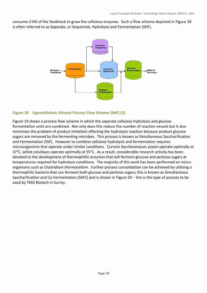
Liquid Transport Biofuels - Technology Status Report, NNFCC, 2007
Page 39
consume 2-6% of the feedstock to grow the cellulose enzymes. Such a flow scheme depicted in Figure 18 is often referred to as Separate, or Sequential, Hydrolysis and Fermentation (SHF).
Figure 18 Lignocellulosic Ethanol Process Flow Scheme (SHF) (2)
Figure 19 shows a process flow scheme in which the separate cellulose hydrolysis and glucose fermentation units are combined. Not only does this reduce the number of reaction vessels but it also minimises the problem of product inhibition affecting the hydrolysis reaction because product glucose sugars are removed by the fermenting microbes. This process is known as Simultaneous Saccharification and Fermentation (SSF). However to combine cellulose hydrolysis and fermentation requires microorganisms that operate under similar conditions. Current Saccharomyces yeasts operate optimally at 37°C, whilst celullases operate optimally at 55°C. As a result, considerable research activity has been devoted to the development of thermophillic enzymes that will ferment glucose and pentose sugars at temperatures required for hydrolysis conditions. The majority of this work has been performed on micro-organisms such as Clostridium thermocellum. Further process consolidation can be achieved by utilising a thermophilic bacteria that can ferment both glucose and pentose sugars; this is known as Simultaneous Saccharification and Co-Fermentation (SSFC) and is shown in Figure 20 – this is the type of process to be used by TMO Biotech in Surrey.

Liquid Transport Biofuels - Technology Status Report, NNFCC, 2007
Page 40
Figure 19 Lignocellulosic Ethanol Process Flow Scheme (SSF) (2)
Figure 20 Lignocellulosic Ethanol Process Flow Scheme (SSFC) (2)
The logical end point of this process integration is known as Consolidated Bioprocessing (CBP) and is shown schematically in Figure 21. In CBP all enzymes are produced by a single microbial community in a single reactor operating under the same conditions. This process is championed by Lynd’s group at Dartmouth College. Lynd is a co-founder of Mascoma Corporation, a lignocellulosic ethanol company pursuing advanced bioprocessing technology. Calculations suggest a potential fourfold reduction in processing costs is achievable when moving from a SSFC to a CBP system.

Liquid Transport Biofuels - Technology Status Report, NNFCC, 2007
Page 41
Figure 21 Lignocellulosic Ethanol Process Flow Scheme (CBP) (2)
Such technology is some way from the marketplace and significant R&D is still required not only in metabolic engineering of improved and more cost effective microorganisms for simultaneous processing but also chemical engineering to address issues such as high solids loading in fermentation processes. As discussed previously, SSCF and CBP are strategies which can be used to maximise the production yield of bioethanol from lignocellulosic feedstock. Where the opportunity for generating value from a multi-product, biorefinery approach utilising the different hydrosylate streams is desired, this could be achieved by, for example, diverting from the ethanol production route a portion of the digesting biomass to make an alternative product or products.
6.1.1.7 Commercial Activity in Lignocellulosic Ethanol Production
Although lignocellulosic ethanol facilities have been in development for many years, it is only now that a number of these are close to commercial realisation. In part, this can be related to continued improvements in biotechnology and reductions in processing costs. Such processes however remain highly capital intensive and currently are not competitive with conventional bioethanol production from food crops. As such, these advanced bioethanol processes present significant risk for venture capital investment and government assistance, such as capital loans or tax allowances, is necessary to facilitate the implementation of the first wave of lignocellulosic ethanol plants. The US government has recently pledged $385M of funds to support the construction of six lignocellulosic ethanol plants. Other proposed lignocellulosic ethanol plants in the United States are receiving significant financial support from state governments.
Table 3 lists the global lignocellulosic ethanol plants under construction, or in planning – further information, especially with respect to the EU plants is shown in Appendix 1 (pilot scale and demo/commercial scale). A number of these processes are differentiated by the proprietary micro-organisms used for sugar fermentation. In addition to these plants, there are a large number of demonstration/pilot plants around the world. A production capacity of 10 million US gallons (~30 thousand tonnes per annum) is considered to be the threshold for commercial scale. Although not of this scale, Bioethanol Japan is reported to be the first company to produce lignocellulosic ethanol on a commercial basis. The Celunol plant in California is likely to be the first operational facility in the US.
A summary of the plants supported by the US DoE grant is provided by Figure 22.
Region Company Scale Location Process Feedstock Timing

Liquid Transport Biofuels - Technology Status Report, NNFCC, 2007
Page 42
Ktpa
USA Abengoa 34 Hugoton, Kansas
SunOpta Mixed 2010
USA Alico 42 Florida Syngas fermentation
Wood, wastes
USA Celunol 90 California Sugar cane waste
2007
USA Colusa 30 California Rice straw 2008
USA BlueFire Ethanol 57 California Arkenol Green & wood waste
USA Iogen 54 Idaho Iogen Mixed 2008
USA JGC Corp 24 California Arkenol Wood waste 2009
USA Mascoma 14.2 Michigan Univ. Tennesee
Mixed woods 2009
USA POET (Broin) 94 Emmetsburg, Iowa
Corn stover 2009
USA Range Fuels 120 Georgia Syngas catalytic
Wood wastes
Ground broken Nov 2007
USA Verenium 4 Louisianna Verenium Bagasse + other
2010
USA Xethanol 150 Georgia Wood 2007
Canada Greenfield Ethanol
32 Ontario / Quebec
SunOpta Wood Chips
Table 3 Lignocellulosic Plant Activity Across the World (2)
Liquid Transport Biofuels - Technology Status Report, NNFCC, 2007
Page 43
region Company Scale
Ktpa
Location Process Feedstock Timing
EU Abengoa 4 Salamanca, Spain
Straw 2006/7
EU Biogasol 40 Denmark Biogasol Straw 2008
EU Inbicon 30+30 Denmark Dong/Inbicon Straw + grain
2009
EU Losonoco Merseyside, UK
MSW On hold
EU Royal Nedalco 150 Sas van Gent
Netherlands
2008
EU/UK TMO Biotech n/a Surrey,UK TMO DDGS, other Q1 2008
China CRAC 5 Heilongjiang Province
SunOpta 2007
Japan Bioethanol Japan
1.1 Osaka Celunol Wood waste now
Japan Marubeni TSK 75 Osaka Verenium 2010
Table 3 Lignocellulosic Plant Activity across the World (Contd.) (2)

Liquid Transport Biofuels - Technology Status Report, NNFCC, 2007
Page 44
Figure 22 Summary of US DoE Funded Projects

Liquid Transport Biofuels - Technology Status Report, NNFCC, 2007
Page 45
6.1.1.8 Lignocellulosic Ethanol SWOT Analysis (1)
2nd Generation Ethanol
Strengths
Product ethanol is identical to ethanol produced from 1st gen plants
Very high GHG savings vs mineral gasoline
Larger range of biomass available for conversion which can be grown on land not used for food production or from waste
Uses whole plant to make fuel
Does not need to use food crops
Much higher yields per hectare of land compared to first generation processes
Weaknesses
Not yet a commercial reality
Ethanol is hygroscopic, has low energy density
High vapour pressure
Development timescale estimate = 5-8 years
More complex process compared to first generation process
More complex feed handling than for 1st generation
C5 sugar upgrading more difficult than C6 to ethanol
3 days conversion time to ethanol compared to 2 for 1st gen (from starch) – increases capital costs and increases risk of product contamination
2nd gen beer is more dilute than 1st generation
Opportunities
High potential to produce chemicals in addition to fuel ethanol
Flexi fuel cars allow greater use of ethanol
Potential to provide a degree of fuel security
New uses for DDGS
New (high value) uses for lignin
Opportunity to mitigate climate change
Can provide more ethanol/ha than 1st generation
Threats
Enzymes could be expensive
Continued low oil prices
Reducing DDGS prices
High capital costs compared to first gen.
Market move to diesel use in the EU
6.1.2 Other Fuels
6.1.2.1 Biobutanol
Development of biobutanol as a fuel substitute has been identified at two UK companies – other developments are in progress worldwide:
BP, Saltend, Hull (in collaboration with British Sugar and DuPont) (25) (13)
Green Biologics, Oxfordshire (17)
Both companies are planning to make biobutanol from cereal derived feedstocks (ie first generation feedstocks). In BP’s case, they plan to convert the first generation ethanol plant they are currently building at Hull to biobutanol – current plans have the project producing ethanol late in 2009 at a rate of 420 million litres/year (320,000 tonnes/year) (13).

Liquid Transport Biofuels - Technology Status Report, NNFCC, 2007
Page 46
Biobutanol is considered an advanced fuel as it (25):
Can be used as both gasoline and diesel substitutes (17)
Can be easily added to conventional fuels and can use the existing supply infrastructure.
Is less susceptible to separation in the presence of water than ethanol/gasoline blends, and therefore allows it to use the industry’s existing distribution infrastructure without requiring modifications in blending facilities, storage tanks or retail station pumps.
Is expected to be potentially suitable for transport in pipelines, unlike ethanol
Does not increase vapour pressure when added to gasoline (has a lower vapour pressure than ethanol), avoiding the need for special gasoline base blends needed to prevent an increase in emissions of volatile organic compounds (VOCs)
Has an energy content closer to that of gasoline than ethanol, so consumers face less of a compromise on fuel economy. This is particularly important as the amount of biofuel in the fuel blend increases
Well suited to current vehicle and engine technologies and does not require automakers to compromise on performance to meet environmental regulations
Can be blended at higher concentrations than bioethanol for use in standard vehicle engines. Currently, biobutanol can be blended up to 10%v/v in European gasoline and 11.5%v/v in US gasoline.
Potential in the future to increase the maximum allowable use in gasoline up to 15-16% volume.
Green Biologics are a small biotech company based in Oxfordshire founded in 2003. They are developing a process called the ABE fermentation which was used in the early twentieth century, falling out of use by the 1960’s in the USA and the UK. Using Clostridium acetobutylicum, the process was originally designed to make mainly ethanol but is now being modified to maximise butanol production with acetone as a byproduct. They aim to have a plant operating by 2010 (17). They are also working on routes using thermophilic bacteria.
In the near term, Green Biologics plan to target readily accessible markets, such as chemical markets before moving to retrofitting existing grain ethanol plants to produce butanol in place of ethanol. In the longer term, they aim to develop full scale cellulosic butanol production facilities.

Liquid Transport Biofuels - Technology Status Report, NNFCC, 2007
Page 47
Biobutanol
Strengths
Bioethanol plants can retrofitted to produce biobutanol
Energy density similar to gasoline
High octane, no sulphur, not toxic
Easy incorporation to fuel infrastructure
Butanol produced is identical whatever the feedstock
Weaknesses
Not yet a commercial reality
Development timescale estimate = 1-4 years
More complex process compared to first generation process.
Opportunities
Potential to produce other chemicals
Potential to contribute a small amount to fuel security (~2% of total transport fuels)
Threats
Enzymes/microbes could be expensive
Sustained low oil prices
Higher investment risk compared to 1st generation ethanol
NB. The type of feedstock used to produce biobutanol will impact the SWOT analysis; for feedstock impacts on biobutanol, consult the SWOT analysis for 1st and 2nd generation ethanol.
6.1.2.2 Furanics (26)
Furanics are an advanced biofuel being developed by Dutch company Avantium, a spin off from Shell. Their focus is to develop biofuels with superior properties to first generation fuels.
Avantium have developed a catalytic process development platform which can be used to make furans, specifically 2,5 dimethylfuran and ethoxymethylfurfural, from hexose containing materials including starch feedstocks such as wheat grain and biomass although the process has not yet been tested on biomass.
Furanics are claimed to have an energy density 40% higher than ethanol, contain no sulphur and are not soluble in water. Independent diesel engine tests have been completed by Interteck in the Netherlands. A number of test runs using different blends of furans in standard automotive diesel were completed. Positive results were obtained which indicated a significant reduction in soot emissions. Further engine tests are planned for 2008 to study longer term effects with particular focus on the toxicological and environmental effects.
A furanics mindmap is presented in Appendix 1.

Liquid Transport Biofuels - Technology Status Report, NNFCC, 2007
Page 48
6.2 Thermochemical Based Processes
This section is concerned with emerging thermochemical routes for producing biofuels. In contrast to the biochemical routes presented in the last section, process technologies for thermochemical conversions are, for the most part, established and in some cases, have been practiced commercially.
Thermochemical processes are primarily focused on the production of diesel substitutes although there are routes available for producing ethanol and gasoline which will be covered in this section.
For the purposes of this study, the thermochemical route has been split into three:
1 Vegetable oil hydrogenation – this is a process, sometimes called generation 1.5, which produces a second generation diesel product from a first generation feedstock (vegetable oil).
2 Pyrolysis – this is a simple, economical process which produces a difficult to handle oil product, sometimes called bio-oil or bio-crude.
3 Biomass to liquids – this process takes biomass and converts it, typically, into a high quality diesel product via Fischer-Tropsch (FT) synthesis. Alternatively, a wide range of other fuels and chemicals can be chosen to be made by substituting the FT process step for other processes.
6.2.1 Vegetable Oil Hydrogenation
From a vegetable oil feedstock, this process produces a high quality diesel product which can be blended in all proportions with fossil diesel (aviation fuel can also be produced). The diesel product is high in cetane, low in aromatics and sulphur and does not contain oxygen.
This process uses existing refining techniques which are well understood by refiners, both economically and technologically. The process is therefore a good fit for refiners allowing them to produce the biofuel they need to meet their RTFO obligations to their own quality standards. Qualitatively, the diesel fuel produced:
Is a renewable, pure hydrocarbon fuel
Is an excellent diesel blending component
Fits existing infrastructure - no incremental costs (blend and forget)
Has no storage stability problems
Is not subject to microbial attack
Has excellent performance in cold climates (unlike FAME)
Has a very high cetane number (80...100)
Is free of aromatics, sulphur, oxygen
Reduces exhaust emissions of NOx, PM, CO
Qualitative fuel quality data are presented in Appendix 2.
Effectively, the process involves the reaction of vegetable oil with hydrogen (typically oil derived if taken from an oil refinery) in the presence of a catalyst. The resulting product is a straight chain hydrocarbon. Figure 23 illustrates the process chemistry.
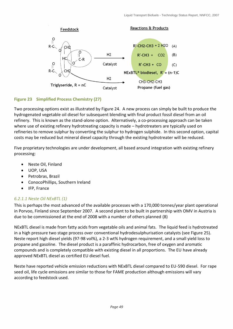
Liquid Transport Biofuels - Technology Status Report, NNFCC, 2007
Page 49
Figure 23 Simplified Process Chemistry (27)
Two processing options exist as illustrated by Figure 24. A new process can simply be built to produce the hydrogenated vegetable oil diesel for subsequent blending with final product fossil diesel from an oil refinery. This is known as the stand-alone option. Alternatively, a co-processing approach can be taken where use of existing refinery hydrotreating capacity is made – hydrotreaters are typically used on refineries to remove sulphur by converting the sulphur to hydrogen sulphide. In this second option, capital costs may be reduced but mineral diesel capacity through the existing hydrotreater will be reduced.
Five proprietary technologies are under development, all based around integration with existing refinery processing:
Neste Oil, Finland
UOP, USA
Petrobras, Brazil
ConocoPhillips, Southern Ireland
IFP, France
6.2.1.1 Neste Oil NExBTL (1)
This is perhaps the most advanced of the available processes with a 170,000 tonnes/year plant operational in Porvoo, Finland since September 2007. A second plant to be built in partnership with OMV in Austria is due to be commissioned at the end of 2008 with a number of others planned (8)
NExBTL diesel is made from fatty acids from vegetable oils and animal fats. The liquid feed is hydrotreated in a high pressure two stage process over conventional hydrodesulphurisation catalysts (see Figure 25). Neste report high diesel yields (97-98 vol%), a 2-3 wt% hydrogen requirement, and a small yield loss to propane and gasoline. The diesel product is a paraffinic hydrocarbon, free of oxygen and aromatic compounds and is completely compatible with existing diesel in all proportions. The EU have already approved NExBTL diesel as certified EU diesel fuel.
Neste have reported vehicle emission reductions with NExBTL diesel compared to EU-590 diesel. For rape seed oil, life cycle emissions are similar to those for FAME production although emissions will vary according to feedstock used.
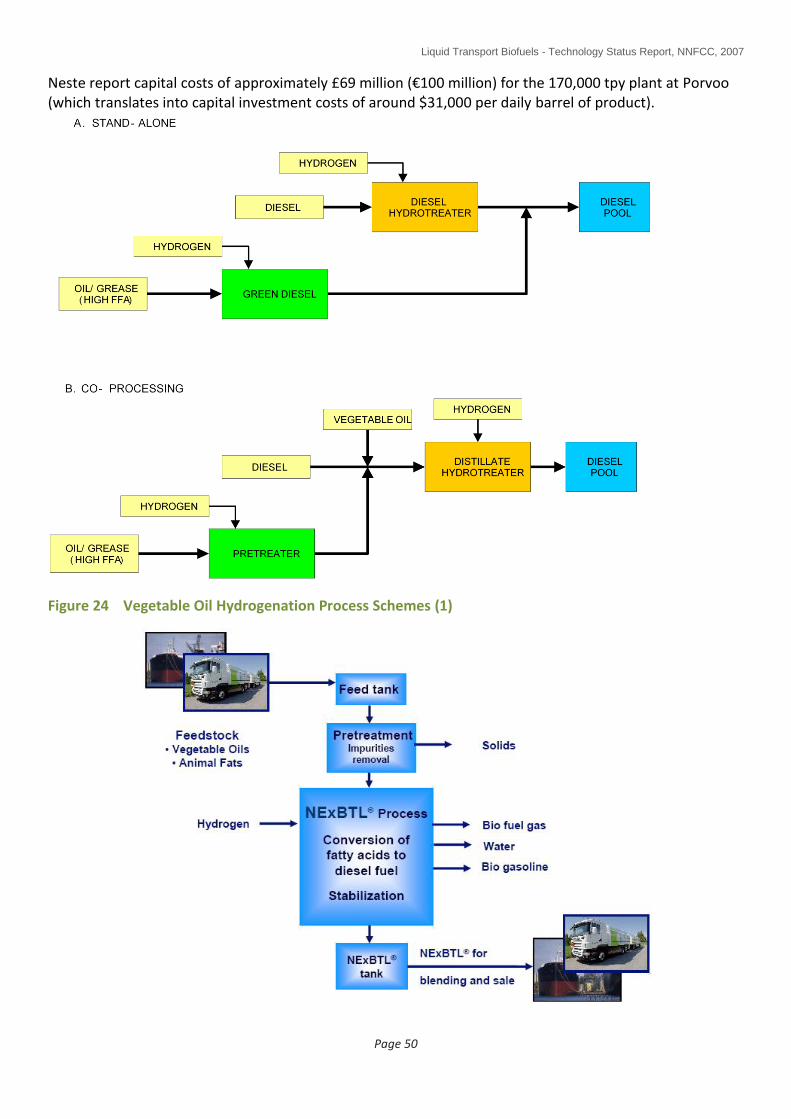
Liquid Transport Biofuels - Technology Status Report, NNFCC, 2007
Page 50
Neste report capital costs of approximately £69 million (€100 million) for the 170,000 tpy plant at Porvoo (which translates into capital investment costs of around $31,000 per daily barrel of product).
Figure 24 Vegetable Oil Hydrogenation Process Schemes (1)

Liquid Transport Biofuels - Technology Status Report, NNFCC, 2007
Page 51
Figure 25 Schematic of Neste NExBTL Process (28)
6.2.1.2 UOP (1)
UOP are a large company who design and construct refinery processing units such as fluid catalytic cracking units which are used to upgrade heavy oils to gasoline.
UOP are developing both stand-alone and co-processing technology for processing vegetable oils and greases in refineries (29). The product is a fully deoxygenated paraffinic diesel, which UOP call “green diesel”. UOP claim high diesel yields (>98 vol%) and good product quality (very high cetane, very low sulphur, similar density and energy value to fossil diesel). Hydrogen consumption is reported in the range 0.8 - 2.9 wt% depending upon the extent of hydrodeoxygenation and decarboxylation reactions.
Development issues include how to address the following:
Minimise operating severity, catalyst requirement and hydrogen consumption for bio-feedstocks.
Minimise need for expensive metallurgy for acidic bio-feedstocks and products.
Removal of bio-feedstock contaminants that can permanently deactivate hydroprocessing catalysts.
Removal of products such as CO, CO2, and H2O, which reduce hydroprocessing catalyst performance.
UOP are working in partnership with Italian company ENI and expect commercial startup of their “Ecofining” process in 2009 (29).
UOP claim much lower production costs compared to FAME and quote typical crude prices of > US$60 per barrel are needed in order to be competitive with fossil diesel.
Recognising that the food vs fuel debate will apply to this process, UOP are driving the development of non edible oils including algal feedstocks which have the potential to supply significant volumes of feedstock (29).
6.2.1.3 Petrobras (1)
Petrobras are developing the HBIO process for production of diesel from biofeedstocks (mainly soy although castor has also been tested at pilot scale). Petrobras plan to implement HBIO in at least four refineries in Brazil by end 2007, with expected vegetable oil consumption of 256,000 m3 per year (approximately 5,000 barrels/day). Further HBIO expansions in Brazil are targeted for 2008 where they expect to build a further five installations processing up to 425,000 m3 of vegetable oil each year.
The HBIO process is a co-processing technology developed for integration into existing refineries. The vegetable oil is blended with some fossil oil and then hydroconverted at high temperature and hydrogen pressure in refinery distillate hydrotreaters, which are used for sulphur reduction and quality control of conventional fossil oil diesel fractions. Petrobras report high diesel yields (>95 vol%) and only a small amount of propane as by-product with this process.
Petrobras claim typical capital costs of around US$8,000 per daily barrel are needed for refinery plant integration of the HBIO process.
6.2.1.4 ConocoPhillips (1)
ConocoPhillips announced commercial production of biodiesel in November 2006 at their small Whitegates refinery in Cork, Ireland. The process uses a vegetable oil hydrogenation technology, developed by ConocoPhillips, to produce a renewable diesel component that meets EU standards. Soybean oil will be

Liquid Transport Biofuels - Technology Status Report, NNFCC, 2007
Page 52
the primary renewable feedstock used, although the plant can also produce renewable diesel using rape seed oil and other vegetable oils (30).
The refinery process appears to be stand-alone scheme with a capacity of 1,000 bpd of renewable diesel. The process uses existing equipment at the refinery. The renewable diesel product is blended and transported with fossil diesel for sale into the Irish fuels market.
6.2.1.5 Institut Francais du Petrole (IFP)
IFP is involved in the development of vegetable oil hydrogenation (31). A request for additional information has been sent to IFP but no response has yet been received.
6.2.1.6 Vegetable Oil Hydrogenation Process SWOT (1)
Vegetable oil hydrogenation
Strengths
High volumetric conversion to diesel product
High product quality, similar to Fischer-Tropsch diesel.
Heating value slightly higher than fossil diesel (FAME heating value is lower than fossil diesel).
Product blends in all proportions with fossil diesel
No need to relax diesel specifications to achieve high biodiesel content.
NOx emissions are not increased (cf Fame)
Does not degrade with time.
No implications for end users or for vehicle technology.
No by-products, such as glycerine
Weaknesses
First generation technology based on vegetable oil and animal fat feedstocks
Little commercial operation/experience compared to Fame.
Additional hydrogen requirement
High capital cost plant compared to FAME
Uncertain investment costs, with reported estimates ranging from $8,000 to $30,000 per daily bbl of product
Similar life-cycle CO2 reduction to first generation FAME process.
Opportunities
Good fit with existing refinery processing
First commercial plants coming to market
Threats
Increased feedstock competition with FAME production, with potential supply and cost impacts
Development of cellulosic diesel production facilities (ie BTL)
6.2.2 Biomass Pyrolysis for the Production of Liquid Fuels (1)
Biomass fast pyrolysis is a process in which organic materials are rapidly heated to 450-600°C in the absence of air. Products are organic vapours, pyrolysis gases and charcoal. After cooling and condensation, a dark brown mobile liquid is formed which has a heating value about half that of conventional fuel oil. This liquid product is often termed “bio-oil”. Typically, 70-75 wt% of the feedstock is converted into bio-oil. The gas by-product can be used within the process to provide the heat requirements so there are no waste streams other than flue gas and ash. The char can be sold as a by-product if there is a market although in the FZK/Lurgi process, the char is ground to a fine powder and

Liquid Transport Biofuels - Technology Status Report, NNFCC, 2007
Page 53
mixed back in with the bio-oil product to make a slurry for future gasification, thereby maximising the energy efficiency of the process.
As produced, bio-oil is a difficult product to use. It contains about 25 wt% water, which cannot be readily separated, and some char. The main concerns with the utilisation of pyrolysis liquid relate to a number of technical issues including:
Acidity (pH 2.5)
Viscosity (~70cP – treacly)
Mix of many chemicals (eg about 5% acetic acid)
Oxygenation
Water content (approx 25% water)
Polymerises if heated
Potential for phase separation
Solids content (mostly char)
Inability to mix with petroleum oil
Typical uses for bio-oil as produced include heat and power production using gas turbines or slow speed static diesel engines or as a liquid fuel which can be used to fire boilers and furnaces (see Figure 26). Future uses which may become important include use as a “biomass densification” process to enable easier and more economic biomass transport to a large scale biorefinery (see Sections 6.2.2.3 and 6.2.3.1) and upgrading to road transport fuels by hydrotreating (see Section 6.2.2.5).
Pyrolysis can also be applied to waste materials such as plastics (eg polyethylene and polypropylene) yielding gasoline and diesel (32). Given that plastics are normally petroleum derived, it’s not surprising that petroleum oil compatible products are produced from plastic pyrolysis unlike the pyrolysis products from biomass which do not mix with petroleum based oils without additional upgrading.
For plastics not containing heteroatoms such as low density polyethylene (ie not PVC), the main gaseous products of pyrolysis are hydrogen and light alkanes and alkenes up to about C4, all of which can be efficiently destroyed by thermal oxidation although at higher pyrolysis temperatures, aromatics can be formed including polycyclic aromatics. Thermal oxidation yields non renewable carbon dioxide in the case of plastics made from crude oil or renewable carbon dioxide in the case of plastics made from biomass via the naphtha product from the BTL process (see Section 6.2.3). (non renewable in the case of petroleum derived plastics).
Figure 26 Example Uses for Bio-Oil
A summary of pyrolysis is provided by Figure 27.
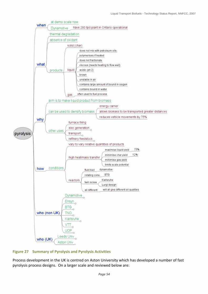
Liquid Transport Biofuels - Technology Status Report, NNFCC, 2007
Page 54
Figure 27 Summary of Pyrolysis and Pyrolysis Activities
Process development in the UK is centred on Aston University which has developed a number of fast pyrolysis process designs. On a larger scale and reviewed below are:

Liquid Transport Biofuels - Technology Status Report, NNFCC, 2007
Page 55
BTG (Belgium)
Dynamotive (Canada)
FZK/Lurgi (Germany)
TNO (Austria)
UOP
Others o Ensyn o BIOeCon o Biomass Engineering (UK)
6.2.2.1 BTG Rotating Cone Reactor
BTG's fast pyrolysis technology is based on the rotating cone reactor (see Figure 28). Biomass particles and hot sand particles are introduced near the bottom of the cone where the solids are mixed and transported upwards by the rotating action of the cone. The produced vapours pass through several cyclones before entering the condenser, in which the vapours are quenched by recirculated oil.
Figure 28 BTG Fast Pyrolysis Technology (1)
Sand and char are recycled to a combustor where char is burned with air to provide the heat required for the pyrolysis process. Excess heat can be used for drying the feedstock. Scaling up of the rotating cone reactor is possible by increasing its diameter. For capacities which require a cone diameter larger than 2 meters, stacking of multiply cones on a single axis leads to the lowest investment costs.
BTG has demonstrated the rotating cone pyrolysis technology on the scale of 250 kg/h based on wood residues. A number of organic materials has successfully been processed in the pilot plant, such as bagasse, palm residues, rice husks, straw, automotive scredder residues, dried sludges, pine wood, olive husks, beech wood, oak wood, switch grass and poplar.

Liquid Transport Biofuels - Technology Status Report, NNFCC, 2007
Page 56
A 50 tpd fast demonstration or prototype commercial plant, processing oil palm wastes, was commissioned in 2005 in Malaysia. The plant processes the empty fruit bunches after the oil bearing fruit have been extracted. The fibrous nature of the palm wastes make it a difficult conversion feedstock; BTG is hoping in future to processs discarded palm leaves as well. BTG is also working on upgrading the bio-oil by decarboxylation and dewatering in order to reduce transport costs, and to improve quality through hydrotreating and partial deoxygenation.
6.2.2.2 Dynamotive Bubbling Fluid-Bed Reactor
Prepared feedstock is fed into the bubbling fluid-bed reactor, which is heated to 450-500°C in the absence of oxygen (see Figure 29). This is lower than conventional pyrolysis systems and, therefore, has the benefit of higher overall energy conversion efficiency. The feedstock flashes and vaporizes and the resulting gases pass into a cyclone where solid char (15-20 wt%) is extracted. The gases enter a quench tower where they are quickly cooled using bio-oil from the process.
Figure 29 Dynamotive Process Technology (1)
The bio-oil (60-75 wt%) condenses and is sent to the product tank, while non-condensable gases (10-20 wt%) are returned to the reactor to maintain process heating. The uncondensed, flammable gases fuel approximately 75% of the energy needed by the pyrolysis process.
Dynamotive's first, large-scale commercial bio-oil pilot plant is located at the Erie Flooring and Wood Products factory site in West Lorne, Ontario, Canada. The plant started operations in early February 2005 with a design capacity of 100 tpd of waste sawdust. Bio-oil produced by the plant is used for fueling a 2.5 MW Magellan Aerospace Limited gas turbine for the production of electricity. Dynamotive have now commenced the expansion of the plant to 130 tpd. The expanded plant is expected to be operational during the second quarter of 2007.
In addition Dynamotive Energy Systems have partnered with Evolution Biofuels to build a modular, decentralised fast-pyrolysis plant that will convert wood residues into bio-oil. The 200 tpd plant will be located in Guelph, Ontario. The modular plant consists of eight modules that are assembled on site. The mechanical erection phase is expected to be completed in February with the start of operations scheduled for the first quarter of 2007. The plant will process, once in full operation, 66,000 dry tonnes of biomass a year and have an energy output equivalent to 130,000 barrels of oil (boe).

Liquid Transport Biofuels - Technology Status Report, NNFCC, 2007
Page 57
6.2.2.3 FZK / Lurgi Fast Pyrolysis Reactor
The FZK/Lurgi pyrolysis reactor was originally developed jointly by Lurgi and Ruhrgas (LR-mixer reactor). Fast pyrolysis is accomplished in a twin screw mixer reactor heated by a solid heat carrier (see Figure 30 and Figure 31).
Figure 30 FZK / Lurgi Pyrolysis Technology (1)
Figure 31 FZK / Lurgi Reactor – Principle of Operation (33)
The aim of the process is the production of sufficient organic and aqueous liquid to suspend the pyrolysis char in order to produce a densified biomass feed for a remote gasifier – it is not the aim of the project to develop a pyrolysis oil which can be used directly as a fuel (see Figure 32). Any bio-oil slurry with a LHV above about 10 MJ/kg which can be pumped and pneumatically atomised with oxygen is suited for the
downstream gasifier. Reduced bio oil quality and yield requirements permit fast pyrolysis process simplifications.
char

Liquid Transport Biofuels - Technology Status Report, NNFCC, 2007
Page 58
Figure 32 FZK Process Chain Showing Decentralised Pyrolysis Plants Providing Common Bio-Oil Feedstock to Centralised Biorefinery (33)
Cold dry straw particles are fed to the circulating hot sand stream in the LR-reactor with a screw feeder.
The sand heater is a vertical shell and tube type vessel. The recirculating loop sand flows down inside the tubes and is heated up with a fluidised sand bed on the shell side, heated and agitated with hot flue gas from the combustion of pyrolysis gas – the recirculating loop sand used to heat the biomass does not come into physical contact with the sand inside the fluidised bed heater. The LR-mixer reactor is mechanically fluidised.
The main characteristic of the LR mixer reactor is two parallel screws which rotate at a few revolutions per second in the same direction and clean each other with intertwining flights. Hot pyrolysis gases, vapours and entrained char particles leaving the reactor firstly enter a hot cyclone which removes the fine char powder from the pyrolysis gas and vapours. Downstream from the cyclone, two sequential quench condensers recover the condensate. Surplus pyrolysis char is pulverised and suspended in the pyrolysis liquid. The dense but pumpable slurries are stored, transported and finally pumped into a pressurised entrained flow gasifier for syngas generation and use. Total condensate yields are about half of the feedstock weight. Energetic efficiency of the process is reported to be 88% (33).
The LR-mixer reactor was first applied as “flash coker” in the early 1950s to produce town gas from coal. The reactor was also used as “sand cracker” with circulating hot sand to produce olefins by cracking liquid hydrocarbons. To test the suitability of the LR-mixer reactor for biomass fast pyrolysis, a process demonstration unit for 10 kg/h biomass throughput was designed, built and put into operation in 2003. Once the suitability of the reactor has been established, it is envisaged that available industrial experience will enable rapid progress through design, construction and operation of a larger pilot facility, planned to be 500 kg/h (33), to a commercial demonstration plant with a feedstock throughput in the order of 10 tonnes/hour.
6.2.2.4 TNO Catalytic PyRos Reactor
The PyRos design is based on a commercial cyclone dust filter operating at 500°C. Sand is used as a heat carrier (in combination with a heated wall) and is injected at the top with the biomass. Catalysts are used in the process to provide catalytic in-situ de-oxygenation of the bio-oil, selective scission of bonds and control of the primary pyrolysis reactions (thereby avoiding secondary reactions which lead to the

Liquid Transport Biofuels - Technology Status Report, NNFCC, 2007
Page 59
formation of gums and chars) (34). New catalyst systems are being developed to improve catalyst/biomass contacting, making use of novel nano catalyst technologies. Interestingly, TNO report that the product oil is acid free (34).
Figure 33 TNO PyRos Catalytic Pyrolysis Technology (34)
Product char solids are transported by recycled vapours from the process. By centrifugal force, the particles are moved to the hot periphery of the cyclone where the pyrolysis process takes place (see Figure 33). Evolved vapours are transported rapidly to the centre of the cyclone and leave the cyclone by the rotating filter. The hot vapours are rapidly quenched with cooled bio-oil and separated in a second cyclone used as a demister for small droplets and aerosols. The remaining gases and char are used to heat up the sand heat carrier and transportation gas. Typically, 70 wt% of the feedstock is converted into oil (containing 20-30% water), 15 wt% into gas and 15 wt% into char.
TNO has demonstrated the PyRos reactor in a 1 kg/hr bench scale unit. Also, they have carried out mathematical modeling to scale up the process and are operating a fully integrated 30 kg/h pilot plant with char/gas combustion, inert heat-up and liquid collection.
Pilot plant operation has demonstrated:
Stable plant operation
Fast startup
50-70% oil yield (depending on biomass)
High quality, solids and acids free oil (<0.01% solids)
Feedstock flexibility (wood, sunflower residues, hemp, coconut husk, jatropha cake have been tested)
TNO indicate that their process is now ready for full scale demonstration (34).
6.2.2.5 UOP (+ ConocoPhillips)
UOP reported at the Next Generation Biofuels Markets Conference, Amsterdam held from 4-5 October 2007, that they are developing pyrolysis as a route to providing an alternative renewable feedstock for refineries (via pyrolysis oil upgrading by hydrocracking) (29). Additionally, a recent announcement by ConocoPhillips indicates that they too are working with Iowa State University on the production and
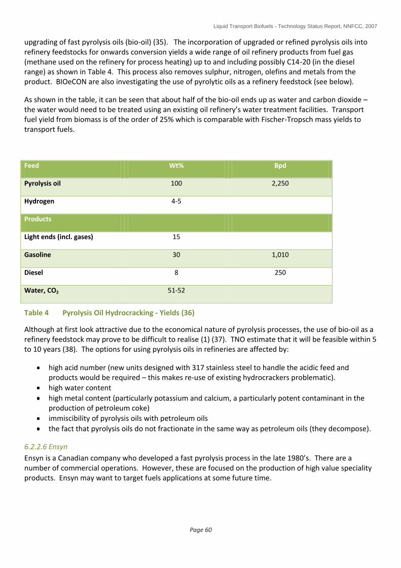
Liquid Transport Biofuels - Technology Status Report, NNFCC, 2007
Page 60
upgrading of fast pyrolysis oils (bio-oil) (35). The incorporation of upgraded or refined pyrolysis oils into refinery feedstocks for onwards conversion yields a wide range of oil refinery products from fuel gas (methane used on the refinery for process heating) up to and including possibly C14-20 (in the diesel range) as shown in Table 4. This process also removes sulphur, nitrogen, olefins and metals from the product. BIOeCON are also investigating the use of pyrolytic oils as a refinery feedstock (see below).
As shown in the table, it can be seen that about half of the bio-oil ends up as water and carbon dioxide – the water would need to be treated using an existing oil refinery’s water treatment facilities. Transport fuel yield from biomass is of the order of 25% which is comparable with Fischer-Tropsch mass yields to transport fuels.
Feed Wt% Bpd
Pyrolysis oil 100 2,250
Hydrogen 4-5
Products
Light ends (incl. gases) 15
Gasoline 30 1,010
Diesel 8 250
Water, CO2 51-52
Table 4 Pyrolysis Oil Hydrocracking - Yields (36)
Although at first look attractive due to the economical nature of pyrolysis processes, the use of bio-oil as a refinery feedstock may prove to be difficult to realise (1) (37). TNO estimate that it will be feasible within 5 to 10 years (38). The options for using pyrolysis oils in refineries are affected by:
high acid number (new units designed with 317 stainless steel to handle the acidic feed and products would be required – this makes re-use of existing hydrocrackers problematic).
high water content
high metal content (particularly potassium and calcium, a particularly potent contaminant in the production of petroleum coke)
immiscibility of pyrolysis oils with petroleum oils
the fact that pyrolysis oils do not fractionate in the same way as petroleum oils (they decompose).
6.2.2.6 Ensyn
Ensyn is a Canadian company who developed a fast pyrolysis process in the late 1980’s. There are a number of commercial operations. However, these are focused on the production of high value speciality products. Ensyn may want to target fuels applications at some future time.

Liquid Transport Biofuels - Technology Status Report, NNFCC, 2007
Page 61
6.2.2.7 BIOeCON (39)
This company is developing a catalytic pyrolysis system which is claimed to result in a pyrolytic oil (bio-oil) product suitable for use as a refinery feedstock. BIOeCON report that their process produces a high quality bio-oil (ie good colour, less acidity) at high yield.
At present, work is ongoing at pilot scale at about 1 kg/hr but they are planning to upscale in 2008. Feedstocks tested to date are wood shavings and bagasse. The process produces about 60-65% oil plus a low calorific value gas plus char which, in a commercial process, be burnt off the catalyst in situ.
BIOeCON report that they expect to be running full industrial trials in 2009/10 followed by implementation/commercialisation.
6.2.2.8 Biomass Engineering (40)
Biomass Engineering, in collaboration with Conversion and Resources Evaluation Ltd (CARE), a company with links to Aston University, are currently building a 250 kg/h flash pyrolysis unit for the production of pyrolysis liquids (bio-oil). This development plant is to be located in Newton Le Willows in the North of the UK. The output oil will be used to fuel an Ormerod diesel engine to produce power (see Figure 26). Future, larger scale plants are planned where the option to extract high value chemicals is desired.
6.2.2.9 UK Research (40)
UK pyrolysis research is ongoing at the following institutions:
Aston University (5 reactors up to 10 kg/h, biomass feedstocks, fluid bed and ablative reactors, analysis, chemicals).
Leeds University (1 kg/h, biomass and wastes feedstocks, fluid bed reactor, analysis).
Imperial College (production of charcoal)

Liquid Transport Biofuels - Technology Status Report, NNFCC, 2007
Page 62
6.2.2.10 Biomass Pyrolysis SWOT (1)
Biomass Pyrolysis
Strengths
Simple technology compared to conversion plant
Converts biomass into an energy carrier (either bio-oil or oil/char slurry)
Energy carrier easier to handle and transport than biomass
Small local units can provide feed for large centralised conversion plant (but see weaknesses)
No waste, by-product heat and power
Weaknesses
Much of the technology has a long development timescale for BTL
Very limited commercial experience and current commercial units are relatively small capacity
Significant scale-up issues for BTL
Would need ~70-130 current commercial units to produce ~30,000 bpd synthetic diesel
Variety of different reactor designs under development, each with different scale up issues
Finery ground and low moisture content biomass feed required
Low quality bio-oil product
Bio-oil difficult to upgrade directly
Loss of conversion efficiency for BTL (around 7 t of dry biomass per t of synthetic diesel needed)
Opportunities
Build on future commercialisation experience of biomass conversion for heat and power applications
Potential to upgrade bio-oil for use as an oil refinery feedstock for onward conversion to gasoline/diesel substitutes
Future improvements in bio-oil quality
Threats
May only be developed for heat and power application, not BTL
Scale up issues may limit any application
6.2.3 Biomass to Liquids (BTL)
This process firstly uses gasification to convert biomass to synthesis gas (also known as syngas), a mixture of carbon monoxide and hydrogen at a consistent, designed ratio with minimal additional components and contaminants such as sulphur, tars and solids. Gasification is a very flexible process with respect to feedstock, and, in principle, many different carbon sources can be used to produce the synthesis gas. The syngas is subsequently converted into useable fuel (and chemical) forms of which many different options exist. These useable fuel forms include the production of:
Synthetic diesel (also known as syndiesel and sometimes “Sunfuel”)
Ethanol (the process also produces methanol and other higher alcohols)
Hydrogen
Methanol
Gasoline
In this section, focus will be directed to the production of high quality synthetic diesel from syngas via the Fischer-Tropsch process since most research, primarily in the EU, is using this route. This route is often

Liquid Transport Biofuels - Technology Status Report, NNFCC, 2007
Page 63
commonly referred to as BTL (Biomass to Liquids). Other routes, including the production of ethanol from syngas which is being commercialised in the USA (Range Fuels announced in November 2007 that construction of a new facility in Georgia began), are described in Section 6.2.4.
BTL is a member of the XTL family where X can represent:
C CTL (coal to liquids G GTL (gas to liquids) W WTL (wastes to liquids) B BTL (biomass to liquids)
For each of the above processes, the first stage is to convert the feedstock into a clean syngas, a mixture of carbon monoxide and hydrogen, typically in a ratio of about two moles of hydrogen to one of carbon monoxide (see Figure 34). Once this has been achieved, the feedstock from which the syngas was derived becomes irrelevant. A key feature of this technology, therefore, is that whatever feedstock is used, the final fuel, for which a number of options are available, is the same.
CTL has been practised since before the Second World War while GTL has been developed more recently, most notably in Qatar. CTL and now GTL plants continue in operation in South Africa and aviation fuel supplied in South Africa is a 50/50 mix of synthetic aviation fuel and standard petrochemical derived aviation fuel. Additionally, on 4th February 2008, Airbus tested one of the four engines on an Airbus A380 Super Jumbo (flying out of Bristol) on GTL fuel supplied by Shell (41).
GTL is a particularly valuable technique for converting “stranded” gas fields into more easily transportable liquid fuels. A number of massive scale GTL plants are being built around the world, particularly in Qatar where SASOL and Shell have built separate complexes.
WTL is a particularly new concept with no plants in operation at present. There is no reason why wastes cannot be converted to syngas via gasification although there may be some engineering challenges to work.
Figure 34 Summary of the BTL Process Stages (3)
6.2.3.1 Gasification / Conversion of Biomass to Syngas
The first stage involves the conversion of biomass into syngas. Of the variety of gasification technologies available (Figure 35), entrained flow and fluid bed gasifiers are currently the most appropriate. Entrained flow gasifiers (Figure 36) are potentially the most suited due to their ability to produce a syngas very low in tars and hydrocarbons. Note that for a CHP unit where a high calorific value gas is desired, then the fluid
Liquid Transport Biofuels - Technology Status Report, NNFCC, 2007
Page 64
bed gasifier is typically more suited (ref Choren and FZK gasifier product gas qualities versus Gussing CHP project gas qualities below).
A potential future type of gasifier which may be highly suited is the plasma gasifier such as that being developed by Startech in the USA (42). A plasma gasifier operates in approximately the same way as an electric arc furnace by steam gasifying the feedstock with a high energy electric arc. The absence of oxygen and the use of steam, potentially mean that the resulting syngas would be expected to contain more hydrogen and less carbon monoxide and carbon dioxide than is produced using entrained flow and fluidised bed gasifiers. However, high energy consumption may be an issue with this type of gasifier.
Entrained flow gasifiers can be imagined to be a burner firing a powdered or atomised feedstock into a furnace with insufficient oxygen provided for full combustion. The insufficient oxygen and high gasification temperatures result in high conversion efficiency to carbon monoxide and hydrogen with reduced production of undesirable constituents such as tars, hydrocarbons and carbon dioxide.
Ash, which for biomass can often be an issue as it melts at low temperature causing corrosion problems, is removed as a liquid slag by design.

Liquid Transport Biofuels - Technology Status Report, NNFCC, 2007
Page 65
Figure 35 Summary of Gasification

Liquid Transport Biofuels - Technology Status Report, NNFCC, 2007
Page 66
Figure 36 Entrained Flow Gasification (43) (33)
Entrained flow gasifiers require a powdered (or atomised) feedstock which is difficult to achieve with solid biomass. However, it is possible to use pyrolysis to pre-densify biomass close to the point of production for more economic transport to a central biorefinery where the BTL plant would be located. Pyrolysis, as noted above, produces a bio-oil product which could easily be atomised for gasification - a number of workers have reported and are driving this approach (eg NNFCC (3), ECN (44), FZK (33), IFP (45)). There is also the potential to use a product termed bio-coal which is a partially carbonised (torrefied) biomass, although this has not yet been tested in an entrained flow gasifier (44). Torrefied biomass is friable and therefore easily pulverised – it is also denser than biomass and can be stored easily without deteriorating. Biomass pellets could also be used but not easily in an entrained flow gasifier – a fluidised bed gasifier would most likely be more appropriate in the case of biomass pellets (Figure 37).
A fluidised bed is formed when a quantity of solid particulate matter such as sand is forced to behave as a fluid, usually by the forced introduction of pressurised gas through the particulate medium. This results in the medium having many properties and characteristics of fluids including the ability to achieve high heat and mass transfer rates.
Although there are a number of entrained flow gasifier suppliers, there are only two entrained flow gasifiers available which have been tested/operated on biomass feedstocks (Choren, Siemens). Fluidised bed gasifiers are more established and suppliers who have tested biomass include TPS (Sweden). Table 5 lists existing large scale gasification suppliers.
Siemens gasifier
depi depi

Liquid Transport Biofuels - Technology Status Report, NNFCC, 2007
Page 67
Company Configuration
E-Gas (ConocoPhillips) Entrained Flow
GE (formerly Texaco) Entrained Flow
Shell Entrained Flow
Kellogg Brown & Root Transport Gasifier
Lurgi Dry Ash Gasifier/Multi-purpose Gasifier
Prenflo Entrained Flow
Advantica BGL Fixed bed
Noell Entrained Flow
Winkler Entrained Flow
KRW Fluid Bed Gasifier
Choren Carbo V – 2 Stage Gasification
TPS Fluid Bed Gasifier
VTT Fluid Bed Gasifier
Siemens (formerly Future Energy) Entrained Flow
Table 5 Gasification Platform Providers for Syngas (3)
A summary of entrained flow and fluidised bed gasifiers with respect to the BTL process is shown in Table 6.
Figure 37 Diagram of Fluidised Bed Gasification (43)

Liquid Transport Biofuels - Technology Status Report, NNFCC, 2007
Page 68
Fluidised bed
Fluidised bed gasifiers are operated below a temperature of 1000°C to guard against problems with ash slagging and sintering in the reactor. Under these conditions, significant amounts of methane are present in the product synthesis gas stream along with medium amounts of tar. To maximise the carbon efficiency of the gasification process the unreacted methane must be converted to synthesis gas in a downstream catalytic reforming step.
Entrained flow
Entrained flow gasifiers are already demonstrated at a large commercial scale for coal gasification. These reactors operate at temperatures around 1300°C and ash slagging is accommodated in the reactor design. At these high temperatures, methane and tar concentrations in the reactor outlet are greatly reduced relative to the fluidised bed system. However, entrained flow reactors require very fine particles of biomass feedstock. Unlike coal, biomass is very difficult to pulverise and grind down to the required particle size.
Table 6 Gasifier Summary (2)
6.2.3.2 Syngas Conditioning and Cleaning
The syngas produced by biomass gasification does not produce the correct molar ratio of hydrogen to carbon monoxide for efficient downstream conversion using the Fischer-Tropsch (FT) process if the more popular cobalt based catalyst is to be used. There is an alternative iron based catalyst system which is able to accommodate variations in the H2/CO ratio but is only used by three out of the eleven FT providers (Table 7).
To achieve the correct molar H2/CO ratio prior to the FT step, the water gas shift reaction is used. Carbon monoxide in the syngas is sacrificed by reacting it with steam to yield carbon dioxide and additional hydrogen (Equation 2). This process operates at around 300°C and 15-25 bar and is commercially available, being in common use in the petrochemical industry.
Equation 1 Water Gas Shift Reaction
Additionally, to avoid catalyst poisoning, the syngas needs to be cleaned of contaminants. Contaminants that must be removed include sulphur, tars (which are a typical contaminant from biomass gasification), acidic gases such as HCl and H2S and solids. As a rule of thumb FT synthesis gas feeds must have ammonia and sulphur containing gases reduced to below 1 ppm vol. and halides and alkalis reduced to below 10 ppb vol (2). Tars must be reduced to such a concentration that no condensation occurs in the FT reactor. Carbon dioxide and methane take no part in the FT reactions and so also are ideally are removed. Carbon dioxide can be removed by commercially available solvent extraction processes such as Rectisol and Sulfinol. These processes will also remove other contaminants in the synthesis gas such as hydrogen sulphide.
As the majority of these impurities are present in syngas streams from coal and oil, commercially available technologies exist for their removal. Both hot and cool gas cleaning options are available. Particulates can be removed by cyclones, electrostatic filters and wet scrubbers. Acid gases can be removed by wet scrubbing. Zinc Oxide filters, or a Rectisol unit, can be employed to remove hydrogen sulphides. However, for tars, there is no effective commercially demonstrated removal technology.
A summary of gas cleaning and conditioning is provided by Figure 38.

Liquid Transport Biofuels - Technology Status Report, NNFCC, 2007
Page 69
Figure 38 Summary of Gas Cleaning and Conditioning
6.2.3.3 Fischer-Tropsch Process
Once cleaned and conditioned, the gas then undergoes Fischer-Tropsch reaction. This is a well established, commercial, process having been practised for many years. The lead suppliers are probably Shell and Sasol (Table 7).
The FT process converts synthesis gas into a mixture of linear hydrocarbons (an excellent property for diesel and naphtha qualities) of varying chain length. The basic reaction can be represented as follows (Equation 2):
O
Equation 2 Fischer-Tropsch Reaction
The products of the Fischer-Tropsch process are a wide range of linear alkanes and alpha-olefins. The distribution of the hydrocarbons is determined by the reaction conditions, catalyst type and the H2/CO ratio of the synthesis gas. The reaction is performed at an operating pressure of 20-40bar and a temperature range of either 200 -250°C or 300-350°C. The lower temperature range produces waxy products which can be hydrocracked to diesel whilst the higher temperature range produces more gasoline range products. The catalysts employed for the reaction at lower temperature are either iron or cobalt based. The more popular cobalt catalysts provide more selectivity to wax products, are more attrition resistant and have higher activity, whilst the cheaper to prepare iron catalysts are less easily poisoned and deactivate less quickly. An advantage of iron catalysts is that they have intrinsic water gas shift activity and can process synthesis gas with low H2/CO ratios, typical of biomass derived syngases prior to water gas shift. The Fischer-Tropsch reaction is highly exothermic and a number of reactor designs have been developed to accommodate this feature including fixed bed, fluid bed and slurry phase reactors.

Liquid Transport Biofuels - Technology Status Report, NNFCC, 2007
Page 70
Company Process Reactor type Catalyst
BP Fixed bed/Slurry FBR/SBCR Co
ConocoPhillips Slurry SBCR Co
Exxon (AGC-21) Slurry SBCR Co
IFP/ENI Slurry EBR/SBCR Co
PDVSA/Intevep (DISOL)
Slurry EBR Co
PetroSA (Synthol) Fluidised Bed CFB CFB Fe
Rentech Slurry SBCR Fe
Sasol (Arge/SAS/SPD) Fixed Bed/Fluidised bed / slurry FBR/FFB/SBCR Fe or Co
Shell (SMDS) Fixed fed FBR Co
Statoil Slurry SBCR Co
Syntroleum Fixed bed / slurry FBR / SBCR Co
SBCR: slurry bed reactor FBR: fluid bed reactor FFB: fast fluid bed reactor EBR: ebullating bed reactor (similar to SBCR but three phase)
NB BP slurry bed process is being developed in Hull – a small scale pilot plant is in operation.
Table 7 FT Suppliers and Process Types (46)
The waxy product from a Fischer-Tropsch process can be broken down into a range of valuable hydrocarbon products such as diesel, kerosene and naphtha. This process is performed using hydrocracking, a standard refinery operation. In principle, the hydrocracking process can be switched from diesel to kerosene mode depending on market conditions.
6.2.3.4 Products
Typically, the FT process is tuned to deliver a heavy hydrocarbon wax product which can then be upgraded by hydrocracking, a standard oil refining process. As noted above, the hydrocracking process can also be tuned to provide the desired product slate (as illustrated by Figure 34).
Tuned to make diesel, a very linear diesel molecule is produced which is low in aromatics and contains no
sulphur. These properties, summarised in Figure 39, provide a very high cetane number and low smoke
emissions on combustion. The high cetane value and low sulphur is important to refiners as it allows them
to blend excess low quality diesel and upgrade it to road transport diesel thereby increasing its margin.
Compared to the EN590 diesel specification, however, XTL diesel is off spec on density (due to the low
aromatics content). Pure BTL diesel has a density around 780 kg/m³ compared to the EN590 specification
of 820 to 845 kg/m³ (a special XTL diesel specification is being developed). However, engine tests indicate
that engines work well with pure XTL diesel – in fact, if the engine is adjusted to account for the lower
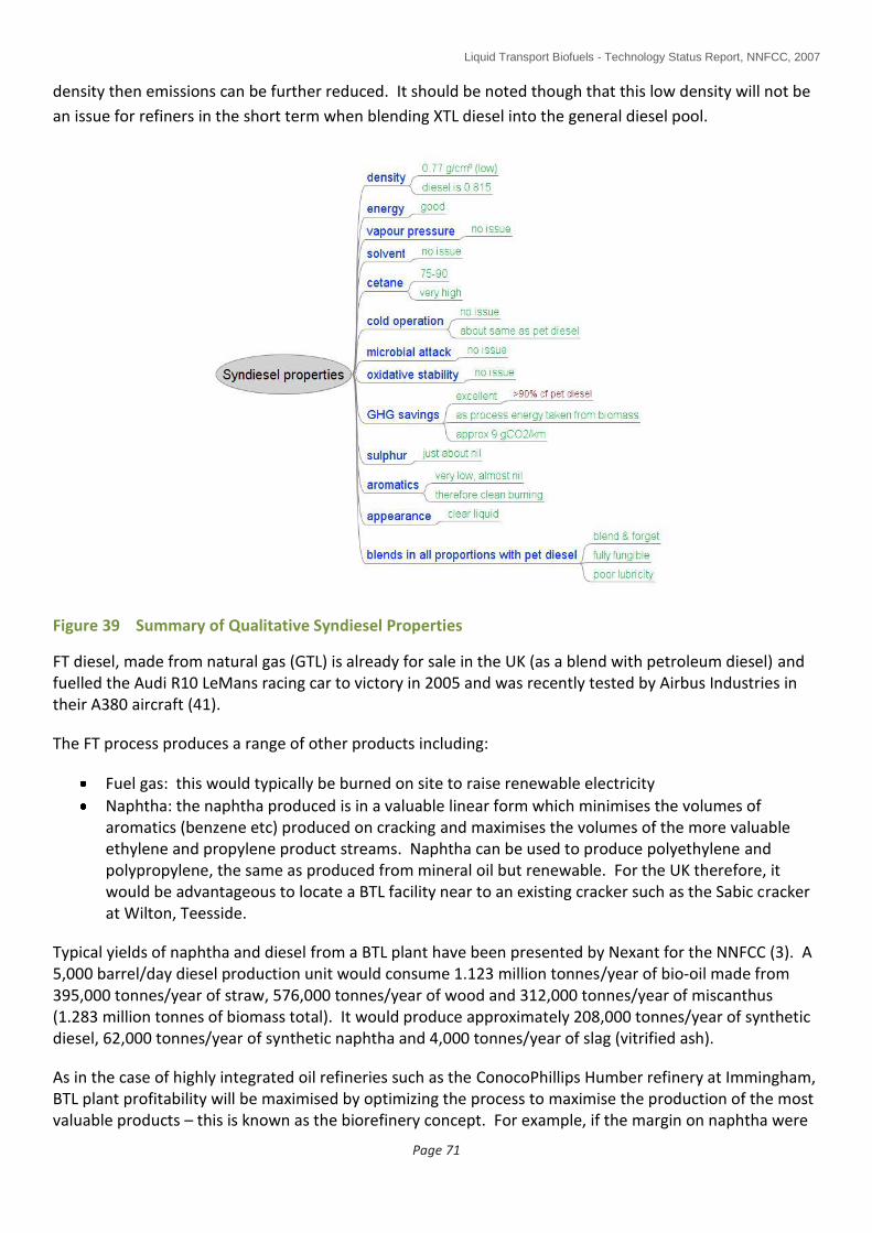
Liquid Transport Biofuels - Technology Status Report, NNFCC, 2007
Page 71
density then emissions can be further reduced. It should be noted though that this low density will not be
an issue for refiners in the short term when blending XTL diesel into the general diesel pool.
Figure 39 Summary of Qualitative Syndiesel Properties
FT diesel, made from natural gas (GTL) is already for sale in the UK (as a blend with petroleum diesel) and fuelled the Audi R10 LeMans racing car to victory in 2005 and was recently tested by Airbus Industries in their A380 aircraft (41).
The FT process produces a range of other products including:
Fuel gas: this would typically be burned on site to raise renewable electricity
Naphtha: the naphtha produced is in a valuable linear form which minimises the volumes of aromatics (benzene etc) produced on cracking and maximises the volumes of the more valuable ethylene and propylene product streams. Naphtha can be used to produce polyethylene and polypropylene, the same as produced from mineral oil but renewable. For the UK therefore, it would be advantageous to locate a BTL facility near to an existing cracker such as the Sabic cracker at Wilton, Teesside.
Typical yields of naphtha and diesel from a BTL plant have been presented by Nexant for the NNFCC (3). A 5,000 barrel/day diesel production unit would consume 1.123 million tonnes/year of bio-oil made from 395,000 tonnes/year of straw, 576,000 tonnes/year of wood and 312,000 tonnes/year of miscanthus (1.283 million tonnes of biomass total). It would produce approximately 208,000 tonnes/year of synthetic diesel, 62,000 tonnes/year of synthetic naphtha and 4,000 tonnes/year of slag (vitrified ash).
As in the case of highly integrated oil refineries such as the ConocoPhillips Humber refinery at Immingham, BTL plant profitability will be maximised by optimizing the process to maximise the production of the most valuable products – this is known as the biorefinery concept. For example, if the margin on naphtha were
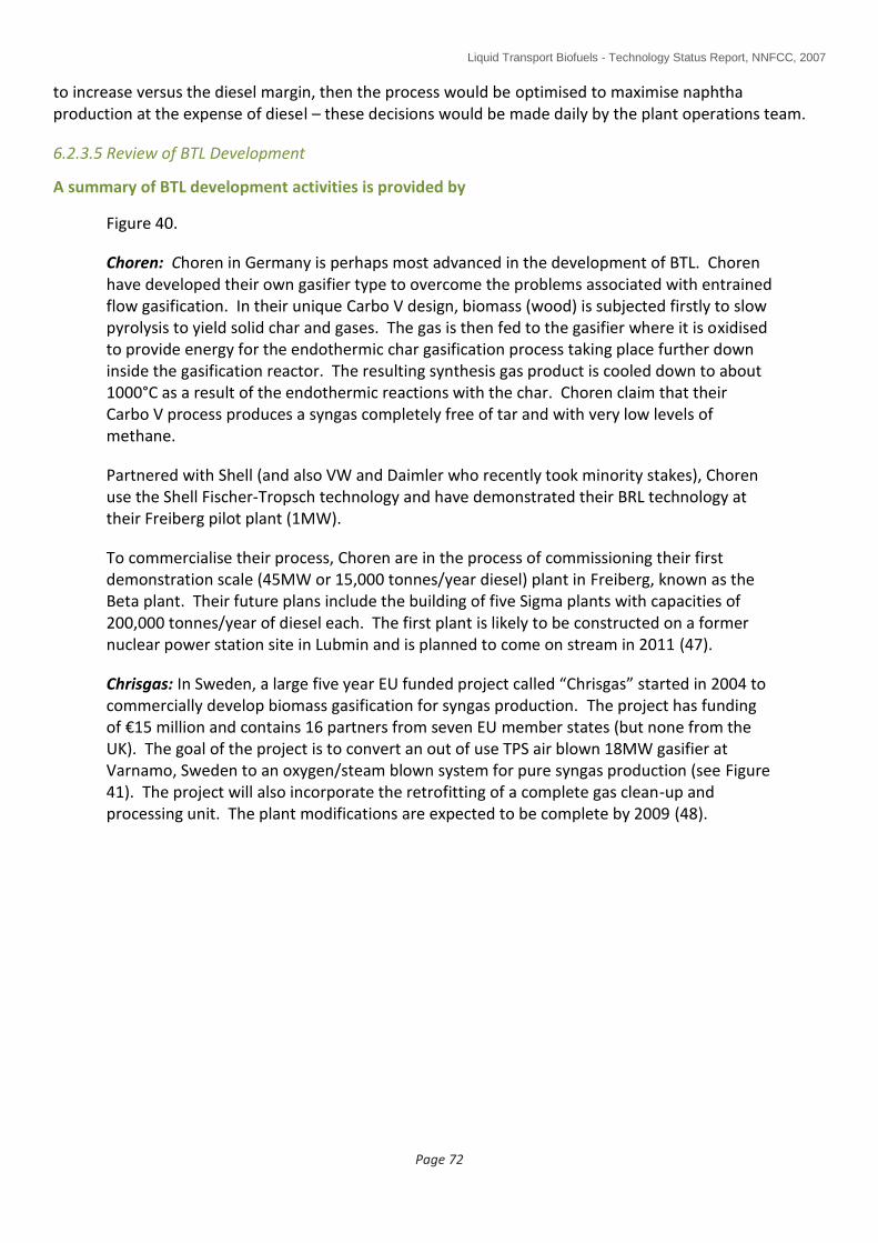
Liquid Transport Biofuels - Technology Status Report, NNFCC, 2007
Page 72
to increase versus the diesel margin, then the process would be optimised to maximise naphtha production at the expense of diesel – these decisions would be made daily by the plant operations team.
6.2.3.5 Review of BTL Development
A summary of BTL development activities is provided by
Figure 40.
Choren: Choren in Germany is perhaps most advanced in the development of BTL. Choren have developed their own gasifier type to overcome the problems associated with entrained flow gasification. In their unique Carbo V design, biomass (wood) is subjected firstly to slow pyrolysis to yield solid char and gases. The gas is then fed to the gasifier where it is oxidised to provide energy for the endothermic char gasification process taking place further down inside the gasification reactor. The resulting synthesis gas product is cooled down to about 1000°C as a result of the endothermic reactions with the char. Choren claim that their Carbo V process produces a syngas completely free of tar and with very low levels of methane.
Partnered with Shell (and also VW and Daimler who recently took minority stakes), Choren use the Shell Fischer-Tropsch technology and have demonstrated their BRL technology at their Freiberg pilot plant (1MW).
To commercialise their process, Choren are in the process of commissioning their first demonstration scale (45MW or 15,000 tonnes/year diesel) plant in Freiberg, known as the Beta plant. Their future plans include the building of five Sigma plants with capacities of 200,000 tonnes/year of diesel each. The first plant is likely to be constructed on a former nuclear power station site in Lubmin and is planned to come on stream in 2011 (47).
Chrisgas: In Sweden, a large five year EU funded project called “Chrisgas” started in 2004 to commercially develop biomass gasification for syngas production. The project has funding of €15 million and contains 16 partners from seven EU member states (but none from the UK). The goal of the project is to convert an out of use TPS air blown 18MW gasifier at Varnamo, Sweden to an oxygen/steam blown system for pure syngas production (see Figure 41). The project will also incorporate the retrofitting of a complete gas clean-up and processing unit. The plant modifications are expected to be complete by 2009 (48).
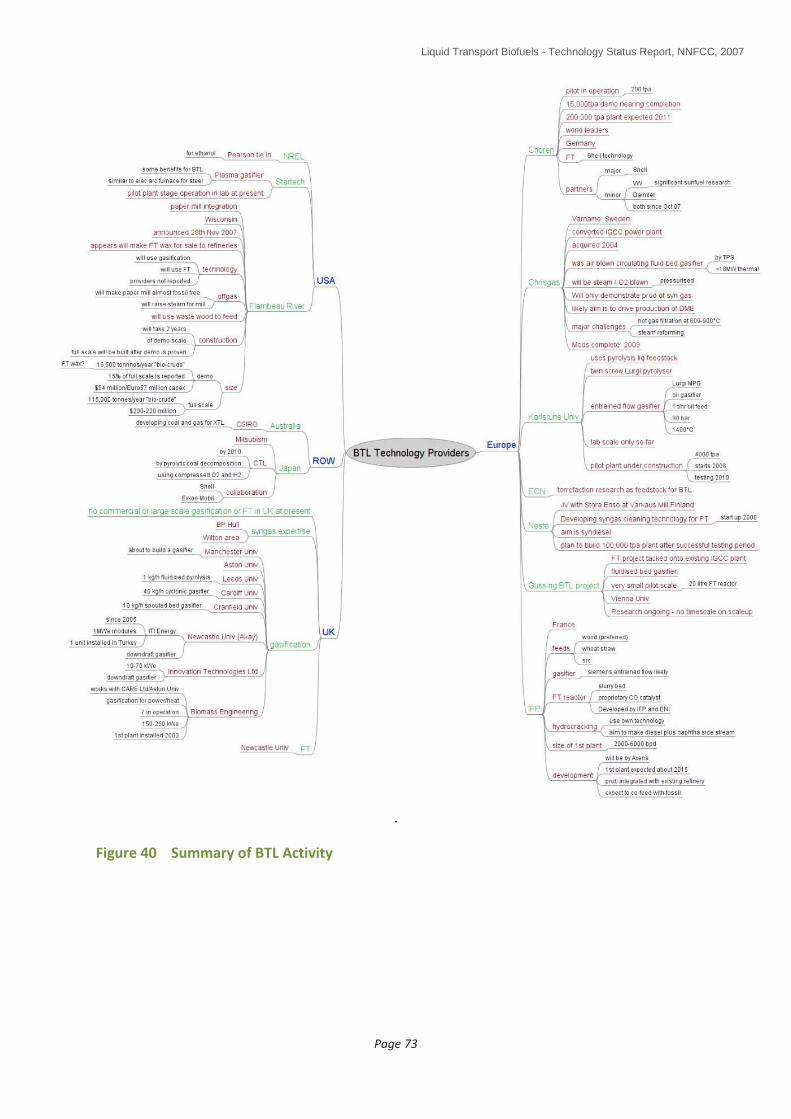
Liquid Transport Biofuels - Technology Status Report, NNFCC, 2007
Page 73
.
Figure 40 Summary of BTL Activity

Liquid Transport Biofuels - Technology Status Report, NNFCC, 2007
Page 74
Figure 41 VVBGC Chrisgas Process (48)
FZK: FZK (who are developing the Lurgi pyrolysis process as noted above) through their Bioliq project have demonstrated the gasification of their pyrolysis oil slurry product at lab scale so far with some testing carried out on a Siemens gasifier at Future Energy in Freiberg (2-5 MWth). Four gasification campaigns have been run in Freiberg with different feedstocks. Gasification conditions were 1200-1300°C and 24 MPa. From a feed slurry containing between 25 and 33% char, the resultant gas contained about 23% hydrogen, 45% carbon monoxide and 15% carbon dioxide (higher than for a commercial gasifier due to higher heat losses). Critically, FZK report no tar and less than 1 vol% methane in the syngas and no significant operational difficulties (33).
Mass and energy balances for the FZK process are presented in
Figure 42 and Figure 43.
Figure 42 FZK Mass Balance (33)
7.5 tonnes
wood or straw
(15% moisture)
5.4 tonnes
condensate /
char slurry +
~1.8 tonnes O2
1.2 tonnes FT
raw products
1 tonne
synthetic fuel +
byproducts
(chemicals,
steam +
electricity)

Liquid Transport Biofuels - Technology Status Report, NNFCC, 2007
Page 75
Figure 43 FZK Energy Balances (33)
FZK are planning to build a 4000 tonnes/year pilot plant starting 2008 with testing beginning in 2010. The biomass condition, fast pyrolysis and slurry preparation processes should now be operational; the gasifier was due to start construction during 2007 and it is planned to have construction of the gas conditioning and fuel synthesis processes start in 2008. 30% of this work is funded by the Fachagentur Nachwachsende Rohstoffe e.V. (German agency for renewable resources) and Lurgi is a “cooperation” partner.
IFP (31) (45): IFP is a French research institute which has a wide ranging portfolio of biofuels projects. With respect to BTL, they have developed, in collaboration with ENI, a proprietary slurry bed Fischer-Tropsch reactor using their own design of cobalt catalyst.
IFP are driving the use of the distributed pyrolysis oil model to allow a larger scale BTL facility while at the same time maintaining acceptable biomass transport economics. However, a key feature of their model is that the bio-oil would be co-fed with heavy, bottom of the barrel oils off a refinery thereby maximizing the potential economy of scale. This scenario does, though, have an impact on the greenhouse gas savings provided per litre of synthetic diesel produced since only a percentage of the finished fuel will be renewable.
Feedstocks which are being targeted are wood (including SRC) and straw. The Siemens entrained flow gasifier is considered to be the most likely gasifier candidate.
IFP estimate that the first plant will be built around 2015 and will be in the 2000-6000 bpd of diesel size range. It is likely to be commercialised by Axens in the same way as for the Esterfip FAME technology.
Neste (8): Neste are working with Stora Enso of Finland and VTT (Finnish Technical Research Centre) to develop BTL from wood based raw materials. A demonstration plant is being built at Stora Enso’s Varkaus Mill in Finland where one of the key work packages will be to develop technology for the purification of syngas for use in the Fischer-Tropsch synthesis.
Energy efficiency in % of energy
initially contained in the biomass
(relative to higher heating value,
HHV)

Liquid Transport Biofuels - Technology Status Report, NNFCC, 2007
Page 76
The demonstration plant will be highly integrated with the paper mill so as to gain maximum cost benefit and to leverage benefit from the existing biomass supply chain to the paper mill. The demonstration plant is expected to start up in 2008.
Commercial plant development is subsequently planned at a scale of 100,000 tonnes/year.
Gussing BTL Project (49): The Gussing BTL project is a Technical University of Vienna Research project. The researchers have built a small Fischer-Tropsch unit which takes a small (7 Nm3/hr) slipstream of syngas from an existing biomass fuelled CHP unit. The majority of the gas is used to raise electricity.
Compared to the entrained flow gasifiers used by FZK and Choren which produce typically <1% hydrocarbons, the Gussing syngas contains 9-12% methane, 2-3% ethane and <1% C3+ hydrocarbons (for a CHP, a fluid bed gasifier is more appropriate than an entrained flow gasifier as the production of hydrocarbons yields a higher calorific value fuel gas). However, it does produce syngas with a H2/CO ratio of 1.6 to 1.8 which is very close to the desired ratio of 2 needed for a cobalt catalyst based FT process.
The FT reactor itself is just 20 litres in capacity but can be run automatically/continuously. It operates at 230°C and 20-22 bar.
Future work is aimed at:
Further gas cleanup development and testing
New catalyst development
FT process optimization
UPM-Kymmene (50): UPM are a forestry business looking to diversify into second generation biofuels, leveraging their pulp and paper experience and assets. They have teamed up with the Institute of Gas Technology in Chicago to build and develop a 6 MWthermal pilot plant (around 10,000 tonnes wood/year if it were run continuously) for the production of clean syngas from wood (which will be shipped to Chicago from Finland). A FT unit will not be built in Chicago as UPM consider the FT process to be fully commercial. This pilot plant is expected to be operational by April 2008.
A key issue identified by UPM is the need to fully integrate heat and power within a BTL complex to ensure profitability.
6.2.3.6 UK Research (40)
UK gasification/Fischer-Tropsch research is ongoing at the following institutions:
Gasification:
Cardiff University (40 kg/h cyclonic gasifier).
Cranfield University (10 kg/h spouted bed gasifier).
Innovation Technologies Ltd., (10-70 kWe downdraft gasifier).
Newcastle University (10 kWe downdraft gasifier – ITI Energy).
Sheffield University (steam gasification of char).

Liquid Transport Biofuels - Technology Status Report, NNFCC, 2007
Page 77
Fischer-Tropsch:
Newcastle University
6.2.3.7 BTL SWOT Analysis (1)
BTL
Strengths
Second generation technology that can convert a wide range of biomass types in very large capacity plants
High product quality compared to FAME
Product blends in all proportions with mineral diesel
Claimed 90% reductions in life cycle CO2 emissions compared to mineral diesel
Much higher yields per hectare of land compared to first generation processes
Able to meet future targets for much large biofuels market
Weaknesses
No commercial operation
Very high capital cost plant compared to first generation processes
Both gasification and conversion steps are inherently high capital cost technologies
Needs 5 t of dry biomass feed per t of synthetic diesel
Higher production cost than first generation unless feedstock cost is low
Long development timescales
Choren is only integrated BTL technology under development
Alternative gasification technologies targeting commercial heat and power applications first
No large centralised conversion plant under development
Opportunities
Build on commercialisation of experience of GTL and CTL technologies
Threats
High capital cost and small scale of BTL plant compared to GTL and CTL plants and oil refineries may severely limit or prevent commercial application
Access to FT technology may be limited
Potential gasification technologies may not be developed for BTL applications
6.2.4 Other Biofuels Derived from Synthesis Gas (2)
A range of options exist to use syngas which are summarised in Figure 44 and Table 8 and
described in this section. Of these technologies, closest to commercialisation at present is
the production of alcohols from syngas.
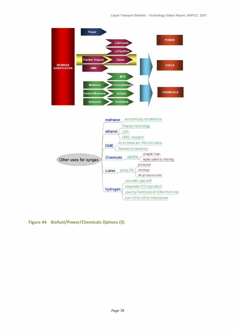
Liquid Transport Biofuels - Technology Status Report, NNFCC, 2007
Page 78
Figure 44 Biofuel/Power/Chemicals Options (3)

Liquid Transport Biofuels - Technology Status Report, NNFCC, 2007
Page 79
Energy Carrier Energy Conversion
Higher Alcohols ICE gasoline oxygenate
Ethanol (synthesis gas fermentation) ICE gasoline oxygenate
Methanol ICE Gasoline oxygenate, Fuel Cell
DME ICE, LPG substitute
Hydrogen ICE , Fuel Cell
Table 81 Other Transport Fuels produced from Bio-derived Synthesis Gas
6.2.4.1 Mixed Alcohols and Ethanol
The production of mixed alcohols from synthesis gas is well known and many processes have been developed to large demonstration scale over the last thirty years. These processes are similar to methanol synthesis but differ in catalyst type and process conditions. Such processes produce a mixed alcohol stream containing methanol, ethanol, propanol, butanols and smaller amounts of heavier alcohols. The original driver for mixed alcohol production was to find an alternative oxygenated transport fuel for blending with gasoline. However, none of these processes were commercialised due to the deficiencies in catalyst performance, fluctuating crude oil price and the subsequent use of MTBE and bioethanol as oxygenated additives for gasoline. A number of research groups have attempted to selectively produce ethanol from synthesis gas with varying degrees of success with most suffering from poor economics due to low catalyst selectivity. Interest in both mixed alcohol and ethanol production from synthesis gas has been rekindled recently due to the increased profile of biofuels. A number of companies are now pursuing the commercialisation of mixed alcohols synthesis from bio-derived synthesis gas.
Pearson Technologies in the US are reported to be developing a biomass to ethanol process via the synthesis gas route.
Recently Syntec have claimed to have developed a proprietary catalyst that delivers unique performance for ethanol production from synthesis gas.
Range Fuels, back by Khosla Ventures, reported on 9th November 2007 that they had started construction of a full-scale biomass (wood chips from foresty residues) to fuel plant in Soperton Georgia (51). The plant is initially expected to produce 57,500 tonnes/year of ethanol plus other alcohols a year with more capacity to be added later.
In contrast to high temperature catalytic routes, the conversion of synthesis gas to ethanol can also be accomplished by fermentation with anaerobic bacteria such as Clostridinium ljungdahlii. This system was identified by workers at the University of Arkansas in the early 1990s and is now being commercialised by BRI. BRI who have benefited from DOE research grants totaling some $2.4 million, now plan to construct the first plant in Tennessee utilising municipal waste as the biomass feedstock. The process produces 75 gallons (0.23 tonnes) of
1 ICE Internal combustion engine
Liquid Transport Biofuels - Technology Status Report, NNFCC, 2007
Page 80
ethanol per tonne of biomass. Lanzatech, a small New Zealand company funded by Khosla Ventures are also developing the biological conversion of carbon monoxide (ie not specifically syngas) to ethanol. Their business aim is to convert high volume industrial waste streams containing carbon monoxide into bio-ethanol (52).
6.4.2.2 Biomethanol and DME
Methanol is a major commodity chemical produced from natural gas (but it can also be produced from coal). The global market for methanol is well over 35 million tonnes, the majority of which is used to manufacture formaldehyde for use in the construction sector. Methanol production technology is mature and exploits economy of scale in huge plants (mega-methanol plants) with production capacities measured in millions of tonnes. Methanol is produced from synthesis gas utilising copper/zinc based catalysts at temperatures of 220 - 300°C and pressures of 50 - 100 bar. Methanol synthesis is an exothermic reaction and reactor design is based on efficient control and removal of heat from the process. The synthesis gas feedstock is currently produced from natural gas and methanol competes with both GTL and LNG (liquefied natural gas) processes from the valorisation of natural gas in remote sites.
Methanol has a long history of use as a replacement for petrol. Throughout the 1980’s and 1990’s, petrol blended with methanol was commercially trialled in various US States. Methanol has a number of advantages as a transport fuel including its high octane rating and cleaner burning characteristics. However, a number of critical issues such as its immiscibility with petrol and high toxicity have led to methanol now being largely discounted as a transport fuel.
Methanol itself can be derivatised to produce a wide range of transport fuels. Methanol is used to manufacture the petrol additive methyl tertiary butyl ether (MTBE), although the use of this additive is now in decline. Methanol is also used as a component of biodiesel. Methanol is an excellent platform molecule and can be derivatised to produce a wide range of other chemical intermediates. With the oil shocks of the 1970s considerable industrial research was directed towards the conversion of methanol to hydrocarbon fuels and petrochemical intermediates. This activity culminated in the commercialisation of the Mobil Methanol to Gasoline (MTG) process which was commercialised in New Zealand in the early 1980’s. This process was abandoned due to the rising cost of natural gas, which made the process uneconomic. The MTG process relied on a highly selective solid-acid zeolite catalyst. By changing the catalyst and process conditions, the MTG process can be modified to produce either light olefins or a mixture of gasoline and diesel. Although not commercially practised both of these processes have been demonstrated at commercially relevant scale and are considered to be “off the shelf” process technology. If the synthesis gas used to produce the methanol is derived from the gasification of biomass then these methanol processes represent alternative synthetic routes to biofuels. However, the MTG process produces a gasoline range product with a very high aromatics content which does not conform to current petrol specifications. It is for this reason that most interest, particularly in Germany, has focused on the methanol to gasoline and diesel process (MOGD) utilising bio-derived methanol feedstock.
The production of biomethanol via biomass derived synthesis gas has been considered for some time particularly as a means to upgrade low value black liquor streams in pulp and

Liquid Transport Biofuels - Technology Status Report, NNFCC, 2007
Page 81
paper mills. However, large scale stand alone bio-methanol plants are now being planned. Some of the synthesis gas output from the Schwarze Pumpe gasification plant in Germany is used to produce around 100,000 tonnes of methanol; this process converts mixed wastes including woody biomass and plastics into synthesis gas for power and chemicals production. The process is economic due to the fact that the waste feedstock commands a gate fee of €150/tonne. In many ways bio-methanol synthesis is more straightforward than BTL, it is a more selective reaction and there are fewer requirements for downstream separation and upgrading. The energy efficiency of biomethanol synthesis is greater than that of the BTL liquids process. However, this difference in energy efficiency will be reduced if the bio-methanol is converted into hydrocarbon fuels via a MTG or MOGD processes.
The catalysts used for methanol synthesis are susceptible to poisoning by impurities such as sulphur compounds so it is essential that the synthesis gas derived from biomass is again of sufficient purity. As with the BTL process, considerable economic and energy efficiency benefits can be realised by integration of methanol synthesis with heat and power production.
Black liquor produced during pulp manufacture represents a very large biomass resource for biomass energy and chemicals production. Conventionally black liquor is combusted in Tomlinson boilers to recover the inorganic pulping chemicals and provide steam for power generation. These Tomlinson boilers are now slowly being replaced by, or augmented with; more efficient air-blown gasification technology supplied by companies such Chemrec and ThermoChem Recovery International. A number of groups have assessed the potential of utilising oxygen-blown entrained flow gasifiers for black liquor conversion to synthesis gas and subsequent conversion to methanol. The biomethanol potential for this route is around 4 million tonnes in Sweden and 28 million tonnes in the US. The BLGMF (Black Liquor Gasification with Motor Fuels Production) project which included consortium members from Chemrec, Methanex, and Volvo concluded that biomethanol produced from black liquor in a modern integrated pulp mill could be produced with high efficiency and be cost competitive against conventional methanol. Because of the sulphite chemicals used in the pulping process, synthesis gas produced from black liquor contains relatively high amounts of sulphur compounds. These sulphur compounds need to be removed prior to methanol synthesis to avoid catalyst deactivation.
As discussed previously biomethanol can be converted into a range of other biofuels using established technology. Work at the Technical University Bergakademie, in Freiberg (TUB-F), Germany is focused on demonstrating large scale biomass conversion to gasoline and diesel utilising a 10 bar fluid bed gasifier combined with methanol synthesis and methanol conversion to gasoline and diesel. The methanol conversion process will utilise the Lurgi MtSynfuel technology.
Methanol can be readily dehydrated to form dimethyl ether (DME). DME is similar in properties to LPG and has a high cetane number (DME is to diesel as LPG is to petrol); consequently it has been promoted as an alternative transport fuel, especially in Scandinavia. In addition to the methanol dehydration route, DME can be produced directly from synthesis gas. The Swedish government is funding research at Volvo for the development of DME powered truck engines. The aim of this activity is to exploit the large volumes of black liquor available in Sweden for biofuels production.

Liquid Transport Biofuels - Technology Status Report, NNFCC, 2007
Page 82
The use of hydrogen carriers and on-board reforming for hydrogen powered fuel cell vehicles may provide a transition option until technology is developed for effective hydrogen storage. Biomethanol represents a suitable carrier for renewable hydrogen for onboard reforming and has advantages over other potential carriers such as ethanol and hydrocarbons.
6.2.4.3 Hydrogen
Hydrogen produced from biomass represents the lowest cost biofuel derived from synthesis gas. The hydrogen content in synthesis gas can be maximised through the water gas shift reaction and then extracted using separation techniques such as pressure swing absorption. Although the majority of hydrogen production is used for chemicals manufacture (mostly ammonia) and oil refining processes, its potential major long term use is as a feedstock for fuel cell vehicles. Life cycle analysis studies have shown that biomass derived hydrogen used in fuel cell cars delivers the highest greenhouse gas savings for a renewable transport fuel (see Section 7.4.2) (53). However, a number of challenging technical and logistical issues remain to be resolved before hydrogen powered fuel cell vehicles become a commercial reality

Liquid Transport Biofuels - Technology Status Report, NNFCC, 2007
Page 83
7.0 DISCUSSION
In the previous section, the current status of production technologies for biofuel production for use in the general fuel pool has been reviewed. The technologies reviewed were:
Biological and chemical processes o Lignocellulosic ethanol technologies o Butanol o Furanics
Thermochemical processes o Vegetable oil hydrogenation o Flash pyrolysis for the production of bio-oil/bio-crude o BTL for the production of synthetic diesel o Other routes including those to olefins, methanol and mixed alcohols
In this section, a comparison of scale of operation, economics, green house gas saving potentials, comparative land use efficiencies and a view on timescales is presented.
7.1 Scale of Operation by Technology
Table 9 shows a summary, by technology type, of the scales of operation achieved to date, what scale is currently or very soon to be in construction and what scales are in planning. Table 9 shows not only the difference in state of development between the different biofuel technologies but also the scale of operation for other advanced technologies (ie GTL and CTL).
Conventional transport fuels are manufactured on massive scales with the largest of the nine UK refineries having a having a daily throughput of about 320,000 barrels/day (ExxonMobil Fawley), equivalent to about 15 million tonnes/year of products (54). The total UK refining capacity was about 1.775 million barrels per calendar day in 2006.
In contrast, biofuels plants in terms of throughput are small – the first large scale 200,000 tonnes/year BTL plants to be built by Choren and consuming of the order of 1.25 million tonnes of biomass per year each will be about 64 times smaller than the current largest UK oil refinery. Size is limited by state of development and feedstock supply chain, especially in the case of the lignocellulosic technologies. Biomass is not very dense (about 0.2 g/cm³) and typically, is difficult to economically transport over long distances. An alternate option would be to consider “densifying” biomass by converting it to:
pellet form,
bio-oil by pyrolysis or
bio-coal pellet by torrefaction (rapid roasting).
The development of the biomass “densification” strategy has led some workers to consider that a 1 million tonnes/year BTL facility could become a reality in the mid-term although a significant paradigm shift would be required for UK agriculture to be able to supply the 6 million tonnes of biomass that would be needed to feed such a plant (55).

Liquid Transport Biofuels - Technology Status Report, NNFCC, 2007
Page 84
largest operating largest confirmed to be built/being built Reported further scale up in planning
who where size tonnes/yr
who where operational from when
size tonnes/yr
who where operational from when
size tonnes/yr
FAME (UK) Biofuels Corp
Teesside 250,000 Ineos Grangemouth 2008 500,000 n/a n/a n/a n/a
1st generation ethanol (UK)
Brit Sugar Norfolk 55,000 BP/Brit Sugar
Hull 2009 400,000 Abengoa Immingham 2010 400,000
Vegetable Oil Hydrogen/ation
Neste Finland 170,000 Neste Austria 2008/9 200,000 Neste global 2015 millions
Pyrolysis Dyn/amotive Can/ada 50,000 n/a n/a n/a n/a n/a n/a n/a n/a
BTL (synthetic diesel)
Choren Germany 200 Choren Freiberg 2007/8 15,000 Choren Lubmin 2009/10 200,000
GTL Sasol Qatar 1.6 million Shell Qatar 2009 + 11 6.7 million n/a n/a n/a n/a
CTL Sasol South Africa
7.2 million n/a n/a n/a n/a n/a n/a n/a n/a
Lignocellulosic ethanol
Marubeni TSk *
Osaka 1000 POET Iowa 2010 89,000 n/a n/a n/a n/a
Thermochemical ethanol
n/a n/a n/a Range Fuels
Georgia 2009/10 113,000 n/a n/a n/a n/a
* Plant design licensed from Verenium Size is in tonnes/year of primary product
Table 9 Relative Scales of Operation by Technology

Liquid Transport Biofuels - Technology Status Report, NNFCC, 2007
Page 85
Existing UK biodiesel capacity is of the order of 538,000 tonnes although high feedstock prices mean that actual production is below this. In construction and planning are a further 1.1 million tonnes although it is not known how much of that capacity will actually be realised.
Existing UK bioethanol capacity is just 55,000 tonnes/year (British Sugar) with a further 255,000 tonnes now in construction and 2.26 million tonnes in planning. Again, it is not known how much of that capacity will actually be realised.
Of the emerging technologies, vegetable oil hydrogenation is operating at the largest scale at 170,000 tonnes/year. This, though, is still smaller than the largest current UK biodiesel plant. Scale up will be limited by sustainable feedstock availabilities and a number of companies are investigating the use of algal feedstocks to permit significant scale up on a sustainable basis.
Pyrolysis is very much emerging with a number of companies operating at the pilot scale (ie about 1500 tonnes/year). However, Dynamotive in Canada supply their units in a modular form and have built an eight module unit with a capacity of 50,000 tonnes/year of pyrolysis oil product.
Of the lignocellulosic technologies, it can be seen that the US government investment is having an effect. Range Fuels is building the largest plant at 113,000 tonnes/year – this is a thermochemical process, similar in theory to the Choren BTL process. The largest advanced biochemical plant is being built by POET in Emmetsburg, Iowa at 89,000 tonnes/year. In Europe, the largest lignocellulosic ethanol plant to be built will be the Danish Biogasol plant at 7,600 tonnes/year which is due to start operating in 2009.
The largest planned BTL facility is the Choren 200,000 tonnes/year Sigma plant of which the first is planned to be built in 2011 in Lubmin (47). Four more are planned to be built by 2015.
7.2 Estimated Technology Timescales
Figure 45 illustrates the estimated times to commercialisation and the scale of technical difficulty for first generation ethanol, FAME biodiesel, hydrogenated vegetable oil, lignocellulosic ethanol and syndiesel (BTL) production. The chart also estimates when alternative feedstocks for biofuel production may become available.
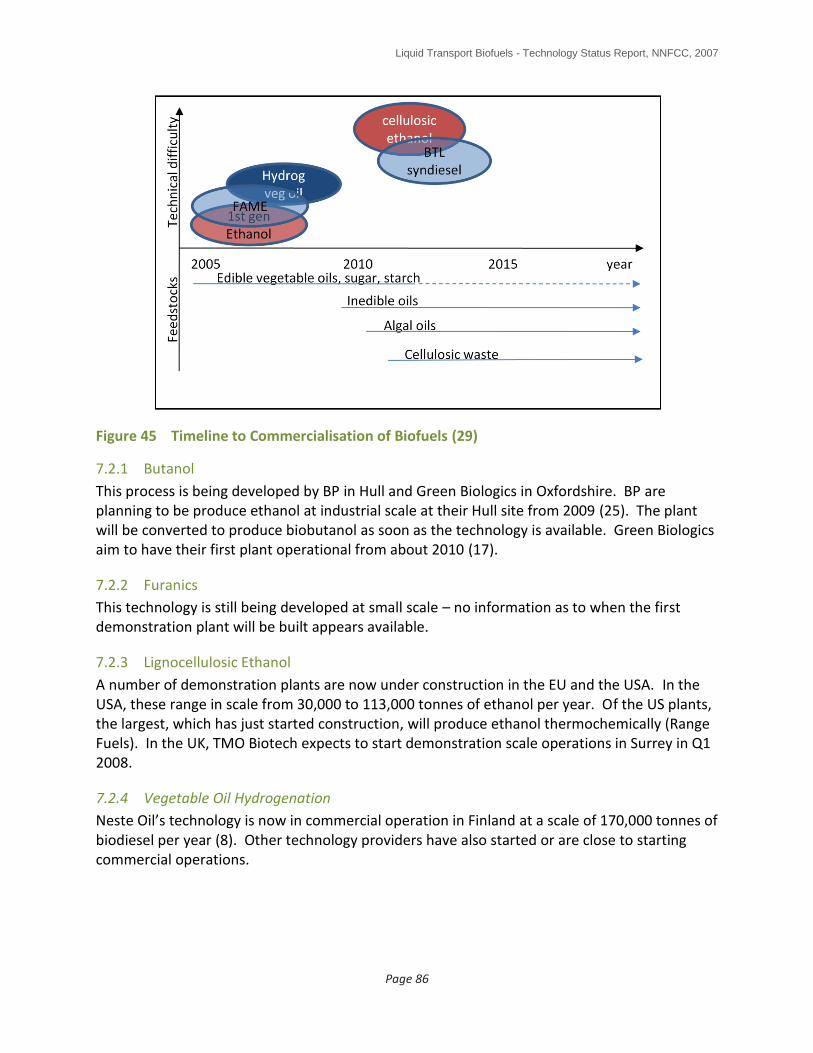
Liquid Transport Biofuels - Technology Status Report, NNFCC, 2007
Page 86
Figure 45 Timeline to Commercialisation of Biofuels (29)
7.2.1 Butanol
This process is being developed by BP in Hull and Green Biologics in Oxfordshire. BP are planning to be produce ethanol at industrial scale at their Hull site from 2009 (25). The plant will be converted to produce biobutanol as soon as the technology is available. Green Biologics aim to have their first plant operational from about 2010 (17).
7.2.2 Furanics
This technology is still being developed at small scale – no information as to when the first demonstration plant will be built appears available.
7.2.3 Lignocellulosic Ethanol
A number of demonstration plants are now under construction in the EU and the USA. In the USA, these range in scale from 30,000 to 113,000 tonnes of ethanol per year. Of the US plants, the largest, which has just started construction, will produce ethanol thermochemically (Range Fuels). In the UK, TMO Biotech expects to start demonstration scale operations in Surrey in Q1 2008.
7.2.4 Vegetable Oil Hydrogenation
Neste Oil’s technology is now in commercial operation in Finland at a scale of 170,000 tonnes of biodiesel per year (8). Other technology providers have also started or are close to starting commercial operations.

Liquid Transport Biofuels - Technology Status Report, NNFCC, 2007
Page 87
7.25 Pyrolysis
Dynamotive in Canada have available a modular pyrolysis process which has been built at 70,000 tonnes/year. Other technology providers are available but are not as close to commercial operation.
In the UK, Biomass Engineering Ltd and CARE Ltd are building a 250 kg/h flash pyrolysis demonstration plant (2,000 tonnes/year). The product from this pilot plant will be used to raise electricity using an Ormerod static diesel engine. Further scale up is planned.
As noted earlier in this report, pyrolysis may be developed to produce a refinery feedstock (55) – the components of the bio-oil may therefore end up in a range of refinery products from refinery fuel gas to mid distillates. UOP are working in this area but no timescale was available.
7.2.6 Biomass to Liquids
The development of BTL for the production of synthetic diesel is most advanced in Europe, particularly in Germany. Choren have operated a small pilot scale plant since 2003 and are about to commission a 15,000 tonnes/year plant in Freiberg. They expect to have their first sigma 200,000 tonnes/year plant operational from about 2011 (47). In the USA, Range Fuels have reported that construction of their 113,000 tonnes/year thermochemical biomass to ethanol plant started construction in November 2007.
Of the lignocellulosic technologies which make a product suitable for blending into the existing fuels infrastructure, BTL is technically perhaps the closest to being commercial, especially at the larger scales of 200,000 tonnes/year and over. It should be noted though that despite the fact that GTL and CTL technologies are well advanced, parts of the BTLprocess remain at the developmental stage (see Table 10). For example, most commercially available entrained flow gasification systems have been developed for coal and oil. Of these, just two are perhaps most suited for biomass gasification (Siemens and Choren).

Liquid Transport Biofuels - Technology Status Report, NNFCC, 2007
Page 88
Technology Status Based on Global Watch Mission 2006 (56)
Gasification commercial in everyday use for coal/oil
Biomass gasification R&D/demo no large scale demonstrations yet
Gas cleanup & conditioning R&D/demo yet to be proven for biomass
FT reactors commercial a number of providers
Hydrocracking Commercial in everyday use
CHP Commercial in everyday use
BTL product applications commercial could be blended immediately
Table 10 BTL Technology Status Summary
7.3 Economics
Four advanced technologies are discussed in more detail in this section. Very approximate capital cost ranges for these and the existing first generation technologies are shown in Table 11. It is clear that the advanced lignocellulosic technologies come in at very high capital cost – more than five to ten times that of the comparably sized first generation biodiesel plants.
In terms of least capital cost, the order of preference for cellulosic biofuels is thermochemical hydrogen (as to be practised at the new coal fired Progressive Energy power station at Wilton), methanol, lignocellulosic ethanol and finally BTL diesel (57). BTL diesel is the most expensive due to the additional, complex unit operations needed to convert syngas into synthetic FT diesel. However, it should be noted that fuel quality is highest from the BTL process (ie fully synthetic diesel ready to use in existing diesel cars with an additive package) while that from pyrolysis is lowest, by a significant margin.
The order in terms of operating costs is the same as for capital costs (57) with BTL diesel being the most expensive of the cellulosic technologies to operate. Cellulosic hydrogen production is cheapest as it only requires water-gas shift reaction and gas separation. Methanol is next cheapest as it requires an additional catalytic step. Fischer-Tropsch diesel and lignocellulosic ethanol have the highest operating costs with lignocellulosic ethanol being slightly cheaper. Fischer-Tropsch diesel requires an additional two steps over the hydrogen route while lignocellulosic ethanol is affected by its inability to convert the non carbohydrate fraction of lignocelluloses into biofuel (57).

Liquid Transport Biofuels - Technology Status Report, NNFCC, 2007
Page 89
Technology Size (tonnes/year) Approximate Cost Level Euros
Relative direct product
useability*
Pyrolysis 70,000 10 million Very low
First Generation (FAME) 250,000 50-100 million Medium
Vegetable Oil Hydrogenation 170,000 100 million High
Hydrogen 200,000 275 million Low
Methanol 200,000 325,000 Low-medium
1st Gen & Lignocellulosic Ethanol 200,000 350-450million Medium
Syndiesel (BTL) 200,000 400-650 million Very high
*the term useability is used here to describe how easily the fuel could be used in the general transport fuel pool in the short to medium term.
Table 11 Approximate Cost Levels for Biofuel Technologies (1) (57) (3)
7.3.1 Vegetable Oil Hydrogenation Economics (1)
This technology is now in commercial operation (since September 2007) (8). Of the five available technologies though, there are significant differences in both the approach and the reported costs of implementation which remain to be resolved. However, it is clear that prospects for this technology in the UK are dependent upon vegetable oil and hydrogen availability and price. A continued increase in vegetable oil prices could severely limit any development of this technology, especially if the cost of production exceeds the 15p/litre buyout price. Overall though, it is possible that the capital investment required may fit into the more general refinery investments necessary as the industry moves towards processing more difficult crude oils.
Estimated costs from Neste, UOP and Petrobras are presented in Table 12.

Liquid Transport Biofuels - Technology Status Report, NNFCC, 2007
Page 90
Company Neste UOP Petrobras
Technology NExBTL Ecofining H-BIO process
Target Feedstock
Vegetable oils and waste animal fats
Low cost waste oil or greases (high fatty acid levels)
Vegetable oils (rape, soya, palm) blended with refinery diesel fractions
Development Status Operational since Sept 2007 in Porvoo refinery, Finland
Commercial startup 2009 (29)
Commercial units in 3 refineries by end 2007 and more planned in 2008
Commercial Concept 170,000 t/yr unit in existing refinery
Options include stand alone and co-processing units
Catalytic hydro conversion of blends in existing refinery hydrotreater units.
Capital Cost ~ €100 million Estimated ~US$7000 per daily barrel of production for a 2000 bbl/day stand-alone unit
~US$8000 per daily barrel
Table 12 Vegetable Oil Hydrogenation Summary (1)
7.3.2 Pyrolysis Economics
Biomass pyrolysis for the production of liquid fuels is very much a technology in the early stages of development towards commercialisation. Of the technologies reviewed above, each offer some potential for use as a densification process for preparing biomass feedstock for BTL or for producing a bio feedstock for blending into a refinery feedstock slate. However, for any widespread use, significant barriers need to be addressed including:
scale-up of proprietary reactor designs to much larger commercial size units
improved bio-oil quality
improved feedstock pretreatment and process integration.
Table 13 summarizes four large scale pyrolysis processes along with approximate costs. As can be seen, pyrolysis processes are relatively capital light – however, this is offset by the nature of the bio-oil product which is difficult to use.

Liquid Transport Biofuels - Technology Status Report, NNFCC, 2007
Page 91
Company BTG Dynamotive FZK-LR TNO
Technology Fast pyrolysis (rotating cone reactor)
Fast Pyrolysis (fluidised bed reactor)
Fast / intermediate pyrolysis in the Lurgi screw reactor
Fast pyrolysis (cyclonic reactor).
Target feedstock Wood and agri residues (<10% moisture)
Wood and agri residues, energy crops
Wood, straw, energy crops
Wood, agri residues, some potential for wastes
Development status
59 tonne/day feed demo plant in Malaysia on palm oil residues
100 tonne/day feed co-generation (heat & power) plant operating in Canada
Part of £15 million Bioliq (BTL) demonstration facility
0.7 t/day pilot plant. Process improvements include zeolite catalyst addition to improve future oil quality
Commercial concept
Target market is power due to low quality bio-oil. Potential for 350 t/day feed plant claimed.
Standard 200 t/day plant design (680 bpd bio-oil). Transport fuels target for future.
Proposed for producing densified biomass for Bioliq BTL process
Looking at Fluid Catalytic Cracker (FCC) system for larger scale plant.
Capital cost ~ €7 million for 50 t/day plant
~US$15 million for 200 t/day plant
No separate costs available
Not disclosed
Development timescale
Not defined First 200 t/day plant planned for Guelph, Canada, 2007
Not defined Not defined (at early stage of development)
Table 13 Biomass Pyrolysis Technology Summary (1)
7.3.3 Lignocellulosic technologies
Lignocellulosic technologies are capital intensive and, being new, also come with a significant level of risk which is a barrier to investment/development. This risk is being offset in the USA by the availability of commercial assistance – this assistance is persuading UK companies working in the lignocellulosic biofuel field to develop at commercial scale in the USA rather than the UK.

Liquid Transport Biofuels - Technology Status Report, NNFCC, 2007
Page 92
Risk also deters EPC (Engineering and Construction Contractors) from bidding to build new projects as they have sufficient lower risk work available (58):
Salaries are rising
Workshops are full
Materials costs are rising rapidly
Increased opportunities – engineering and construction management companies have only so many people – maximise profit per work-hour
Labour market is tight. India – cost of one equivalent hour of engineering is rising – outsourcing to China
However, there remains, in the UK, the potential for lignocellulosic technologies to be “bolted on” to existing first generation plants. For example, the TMO Biotech technology can be used to extract additional ethanol from the fibre fraction of the DDGS byproduct from first generation ethanol plants leaving a more concentrated protein behind. Alternatively, a lignocellulosic plant processing straw could be co-located next to an existing first generation wheat grain ethanol plant so that the existing (expanded) distillation plant, for example, can be synergistically used.
7.3.3.1 Lignocellulosic Ethanol (Biochemical) Economics
NNFCC have commissioned Black and Veatch to carry out a similar study to Nexant’s (3) on lignocellulosic ethanol technologies in 2007/8. Unfortunately, the project has only recently started and no capital cost estimations are yet available. However, it is known that the biochemical route to producing ethanol from biomass is capital intensive, although not as intensive as BTL. Wright and Brown (57) estimate that a 50 million US gallon/year lignocellulosic ethanol plant would cost about 86% of the cost of a 35 million US gallon/year BTL plant (although unfortunately they have not used the same base years for their figures).
There are a large number of reports in the literature that detail projected economics for the production of ethanol from a variety of lignocellulosic feedstocks (2). Projected lignocellulosic ethanol production costs have reduced from over $4 per gallon to $0.5 per gallon with improvements to process integration and reductions in cellulose enzyme costs. To illustrate this further three studies are highlighted below:
Detailed studies have been performed by NREL on the economics of a 180 thousand tonne per annum bioethanol plant using corn stover as the biomass feedstock. The total forecast investment was $200M and the ethanol price calculated to be $1.28/gallon (2006 basis). Corn stover feedstock at $35/dry tonne accounted for 34% of the cost contribution. It should be noted that this price incorporated future reductions in enzyme costs and at current enzyme costs the ethanol price would be closer to $1.5/gallon. This figure is line with the quoted production costs for ethanol produced from cereal straw in the Iogen process ($1.44/gallon ethanol).
A study by Royal Nedalco, ATO-BV and the University of Delft reported that a 150 thousand tonne per annum capacity bioethanol plant utilising a range of biomass

Liquid Transport Biofuels - Technology Status Report, NNFCC, 2007
Page 93
feedstocks would require an investment of the order of €235-313 million (wheat straw = €235M, verge grass = €313M). The bioethanol product cost was calculated to be 0.75 €/litre for wheat straw and 0.92 €/litre for verge grass.
A study by EEDA estimated that a 150 thousand tonne per annum capacity bioethanol plant utilising UK biomass feedstock would require a capital investment of the order of £134 - 143 million and the bioethanol costs would be 80p/litre for miscanthus, 78p/litre for SRC, 74p/litre for forestry residues and 54p/litre for wheat straw.
Although benefiting from considerably cheaper feedstocks compared to first generation processes, lignocellulosic processes currently do not appear competitive with bioethanol produced from starch and sugar feedstocks. The increased capital and variable costs associated with lignocellulose processing can be traced to a number of key elements of the process namely:
High cellulose enzyme costs
High capital and operational costs of the pretreatment section
Long residence time associated with hydrolysis and fermentation
These elements remain the focus of continued R&D to improve the cost competitiveness of the lignocellulosic ethanol routes. Another important area of focus is the generation of higher value from the various co-product streams that exist in such processes.
7.3.3.2 Biomass to Liquids Economics
BTL plants, as with GTL and CTL plants, are large, complex and highly integrated multi-process
facilities. Such complexes benefit greatly from economies of scale.
Nexant, who were commissioned by the NNFCC in 2006 to assess the feasibility of a UK BTL
plant, estimated the capital cost of a 200,000 tonnes/year BTL facility in the UK, fed with bio-oil
from eleven regionally located pyrolysis plants, at approximately €600 million (3) (enough to
build about 10-12 first generation FAME plants). At the base case crude oil price of $65/barrel,
(which is close to the price used to calculate investment decisions), a IRR of 11% was calculated.
Although positive, this is perhaps not sufficiently appealing to investors at present, especially
given the risks associated with developing a new and complex process in the UK. However, UK
and international company interest in the NNFCC/North East IBS (Integrated Biomass to Syngas)
team project to establish a thermochemical biofuels plant in Teesside is building, especially
given the expected introduction in 2010 of rewards for biofuels according to their carbon
savings.
Both small and large BTL plants can benefit from integration into existing infrastructure. For
instance, smaller BTL plants can be integrated into existing pulp mills by replacing Tomlinson
water tube boilers with black liquor gasification systems whist large BTL plants can benefit from
co-locating with existing oil refinery infrastructure. Major benefits in energy efficiency and
Liquid Transport Biofuels - Technology Status Report, NNFCC, 2007
Page 94
process economics can be accrued by integrating both power generation and BTL fuel
production; this can be achieved by utilising the off-gas (light hydrocarbons) from the Fischer-
Tropsch process to generate heat and electricity. The production of biofuels, heat and steam is
known as tri-generation or polygeneration. The integration of power production within the BTL
process also allows the possibility of other process configurations. For example, the Fischer-
Tropsch unit itself operates on a relatively low conversion per pass of synthesis gas with large
recycles. With integrated power production it becomes feasible to operate the Fischer-Tropsch
unit on a once-through basis and feed the unconverted synthesis gas to a gas turbine for heat
and power generation.
BTL could also develop by taking advantage of the proposed system of double ROC certificates
for companies generating power through advanced technologies. A developer who installs a
suitable gasifier to make syngas for use to generate power through combustion could, at a later
date if economics permit, install a commercially available Fischer-Tropsch unit to use all or part
of the syngas generated. This setup would also benefit from co-location at a refinery to make
use of the existing refining infrastructure.
Short to medium term costs for BTL liquids are around triple that for conventional mineral oil
diesel. However with technology development and economies of scale, studies show that at
high crude oil price and with favorable fiscal incentives, BTL synthetic diesel can be competitive
against mineral oil diesel.
7.4 Greenhouse Gas Savings (GHG)
In this section, reported biofuel greenhouse gas savings are briefly compared with gasoline and
diesel and with electricity with biomass. A full and robust evaluation is provided by the
Concawe / Eucar / JRC report (53).
7.4.1 Comparison of Transport Fuels
From a fuels point of view, greenhouse gas savings can be reported as Well to Tank, Tank to
Wheels and Well to Wheels:
Well to tank (WTT) this evaluation accounts for the energy expended and the associated green house gas emissions emitted in the steps required to deliver the finished fuel into the fuel tank of a vehicle.
Tank to wheels (TTW) this evaluation accounts for the energy expended and the associated green house gas emissions emitted when a fuel is consumed by a vehicle.
Well to wheels (WTW) this evaluation combines the WTT and TTW figures to achieve an overall assessment from production through to consumption of energy expended and associated green house gas emissions.

Liquid Transport Biofuels - Technology Status Report, NNFCC, 2007
Page 95
Typically, on a well to wheels basis, both petrol and diesel derived from crude oil emit a total of about 160-165 gCO2 eq/km1 . [Note that synthetic diesel made via gas to liquids (GTL) is slightly worse than crude oil derived diesel while coal derived CTL (coal to liquids) synthetic diesel has about twice the GHG emissions compared to crude oil derived diesel].
Greenhouse gas emissions from first generation technologies such as FAME biodiesel and ethanol are about half of those from petrochemical fuels although savings can vary widely depending on the feedstock (eg soy derived biodiesel vs rape derived biodiesel as shown in Figure 46) and how the biofuels are made. For example, if coal is used to raise steam for ethanol distillation, then greenhouse gas savings can be negligible and perhaps even negative. Similarly, for sugar cane ethanol, because energy for process use is provided by burning the waste bagasse, then the potential greenhouse gas savings are high.
Concawe do not present any data for butanol and furanics since these are very new biofuels. BP estimate that the GHG savings for biobutanol will similar to those from bioethanol per unit of energy (25). Again, these have the potential, in the same way as first generation ethanol, to be variable depending on how the butanol is produced.
Figure 46 Well to Wheels GHG Emissions for Biofuel Pathway (53) (8)
Again, Concawe do not report GHG savings data for the production of biodiesel via the vegetable oil hydrogenation route or for pyrolysis oil (bio-oil). For the vegetable oil
1 gCO2eq/km – units are grams of equivalent CO2 emitted per vehicle km travelled. The equivalent CO2 concept
allows the additional greenhouse gas emissions from other, more potent, greenhouse gases such as methane and nitrous oxides to be taken into account.
159
7434
9
82
340
170 163
115
4921
4420
0
50
100
150
200
250
300
350
400
min
eral diesel
RM
E
SME
BTL
HV
O (N
este)
CTL
GTL
petro
l
ethan
ol, n
at gas
ethan
ol, straw
CH
P
sugar can
e ethan
ol
2n
d gen
farmed
wo
od
2n
d gen
wh
eat straw
g C
O2
eq/k
m

Liquid Transport Biofuels - Technology Status Report, NNFCC, 2007
Page 96
hydrogenation route, Neste report figures of 1.3 to 2.6 tonnes of CO2 per tonne of biodiesel compared to 3.8 for petrochemical diesel which, on average, is about as good as the FAME process (8). This agrees with NNFCC calculations based on data taken from Nippon oil (59). However, it is important to note that as different studies will likely not have used the same boundaries and methodological assumptions, uncertainties in data analysis exist and caution should be used when comparing these data from different life cycle assessment studies.
GHG savings figures for pyrolysis oil are not available as, currently, the product oil is not directly useable for transport fuel applications.
Lignocellulosic technologies such as BTL provide the most potential for GHG savings (see Figure 46). This is mainly because:
the energy used within their production processes is derived from the biomass feedstock,
of lower fertilizer usage and
of the higher biomass production rate per hectare.
7.4.2 Comparison with Electricity from Biomass
Using biomass for electricity and heat generation typically provide enhanced greenhouse gas
savings per hectare of land compared with biofuels as shown in Figure 47. However, it must be
noted that in the near to midterm, only biofuels can provide large scale vehicle exhaust
greenhouse gas emission reductions.
Figure 47 CO2 Avoidance from Alternative Uses of Land (53)
0 10 20 30
Syndiesel (wood gasification)
Hydrogen + fuel cell (wood gasification)
Hydrogen + IC engine (wood gasification)
FAME (rape seeds, glycerine as chemical)
Ethanol (wood)
Ethanol (wheat grain, DDGS to heat/power, straw CHP)
Ethanol (wheat grain, DDGS to animal feed, Nat gas gas …
Ethanol (sugar beet, pulp to animal feed)
Elec (wood gasif vs coal state-of-art conventional)
Elec (wood gasif vs Nat gas CCGT)
tonnes CO2 avoided per ha per year
fuel naphtha

Liquid Transport Biofuels - Technology Status Report, NNFCC, 2007
Page 97
In the above figure derived from the Concawe report (53), a hypothetical hectare of land has
been considered and the carbon dioxide “avoidance potential” for different feedstocks and
process routes shown. As has been reported elsewhere (60), using biomass to produce
electricity in most cases provides the largest potential for greenhouse gas savings. However,
biofuel savings can sometimes provide the more effective land use for greenhouse gas
mitigation, for example in cases such as where biomass replaces conventional gas fired power
stations,.
Of the technologies shown in Figure 47, electricity produced from wood as opposed to that
produced from coal and hydrogen produced from wood gasification and used in a fuel cell have
the highest carbon dioxide avoidance potential, both exceeding that of electricity generation
from wood vs electricity production from natural gas in a combined cycle gas turbine system
(CCGT). This is followed by hydrogen used in an internal combustion engine. Of the nearer
term technologies available for effective transport applications, BTL is the most attractive
having the potential to avoid about 3.25 times that of FAME. FAME and ethanol are less
attractive because of their lower (agricultural) yields and because they do not deliver vehicle
efficiency gains. However, despite these benefits, BTL is still only able to provide about three
quarters of the savings that can be achieved by electricity generation from wood gasification
versus electricity production by natural gas CCGT.
7.5 Comparative Land Use Effectiveness
In this section, the energy produced in the fuel, excluding any byproducts, per unit area of land
is considered. As the UK Biomass Strategy Report compares the efficiency of converting
biomass to heat, electricity and transport fuels, electricity and heat technologies are included in
this section to permit direct comparison with the liquid biofuel technologies discussed
throughout this report (61).
An often quoted benefit of second generation or lignocellulosic biofuels is the fact that more
fuel is produced per hectare of land since the whole plant can be used to produce fuel
compared to just the oil seed or wheat grain for first generation biodiesel and bioethanol made
from rape and wheat. These differences are illustrated in terms of litres of diesel equivalent
produced per technology per hectare per year in Figure 48.
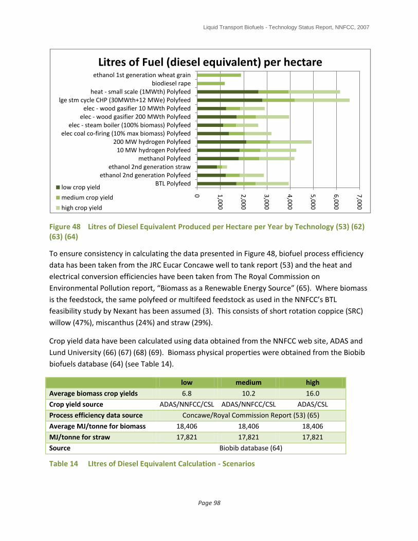
Liquid Transport Biofuels - Technology Status Report, NNFCC, 2007
Page 98
Figure 48 Litres of Diesel Equivalent Produced per Hectare per Year by Technology (53) (62) (63) (64)
To ensure consistency in calculating the data presented in Figure 48, biofuel process efficiency
data has been taken from the JRC Eucar Concawe well to tank report (53) and the heat and
electrical conversion efficiencies have been taken from The Royal Commission on
Environmental Pollution report, “Biomass as a Renewable Energy Source” (65). Where biomass
is the feedstock, the same polyfeed or multifeed feedstock as used in the NNFCC’s BTL
feasibility study by Nexant has been assumed (3). This consists of short rotation coppice (SRC)
willow (47%), miscanthus (24%) and straw (29%).
Crop yield data have been calculated using data obtained from the NNFCC web site, ADAS and
Lund University (66) (67) (68) (69). Biomass physical properties were obtained from the Biobib
biofuels database (64) (see Table 14).
low medium high
Average biomass crop yields 6.8 10.2 16.0
Crop yield source ADAS/NNFCC/CSL ADAS/NNFCC/CSL ADAS/CSL
Process efficiency data source Concawe/Royal Commission Report (53) (65)
Average MJ/tonne for biomass 18,406 18,406 18,406
MJ/tonne for straw 17,821 17,821 17,821
Source Biobib database (64)
Table 14 LItres of Diesel Equivalent Calculation - Scenarios
0 1,0
00
2,0
00
3,0
00
4,0
00
5,0
00
6,0
00
7,0
00
BTL Polyfeedethanol 2nd generation Polyfeed
ethanol 2nd generation strawmethanol Polyfeed
10 MW hydrogen Polyfeed200 MW hydrogen Polyfeed
elec coal co-firing (10% max biomass) Polyfeedelec - steam boiler (100% biomass) Polyfeed
elec - wood gasifier 200 MWth Polyfeedelec - wood gasifier 10 MWth Polyfeed
lge stm cycle CHP (30MWth+12 MWe) Polyfeedheat - small scale (1MWth) Polyfeed
biodiesel rapeethanol 1st generation wheat grain
Litres of Fuel (diesel equivalent) per hectare
low crop yield
medium crop yield
high crop yield
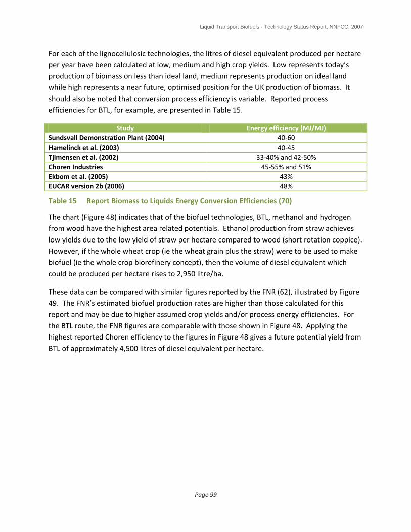
Liquid Transport Biofuels - Technology Status Report, NNFCC, 2007
Page 99
For each of the lignocellulosic technologies, the litres of diesel equivalent produced per hectare
per year have been calculated at low, medium and high crop yields. Low represents today’s
production of biomass on less than ideal land, medium represents production on ideal land
while high represents a near future, optimised position for the UK production of biomass. It
should also be noted that conversion process efficiency is variable. Reported process
efficiencies for BTL, for example, are presented in Table 15.
Study Energy efficiency (MJ/MJ)
Sundsvall Demonstration Plant (2004) 40-60
Hamelinck et al. (2003) 40-45
Tjimensen et al. (2002) 33-40% and 42-50%
Choren Industries 45-55% and 51%
Ekbom et al. (2005) 43%
EUCAR version 2b (2006) 48%
Table 15 Report Biomass to Liquids Energy Conversion Efficiencies (70)
The chart (Figure 48) indicates that of the biofuel technologies, BTL, methanol and hydrogen
from wood have the highest area related potentials. Ethanol production from straw achieves
low yields due to the low yield of straw per hectare compared to wood (short rotation coppice).
However, if the whole wheat crop (ie the wheat grain plus the straw) were to be used to make
biofuel (ie the whole crop biorefinery concept), then the volume of diesel equivalent which
could be produced per hectare rises to 2,950 litre/ha.
These data can be compared with similar figures reported by the FNR (62), illustrated by Figure
49. The FNR’s estimated biofuel production rates are higher than those calculated for this
report and may be due to higher assumed crop yields and/or process energy efficiencies. For
the BTL route, the FNR figures are comparable with those shown in Figure 48. Applying the
highest reported Choren efficiency to the figures in Figure 48 gives a future potential yield from
BTL of approximately 4,500 litres of diesel equivalent per hectare.

Liquid Transport Biofuels - Technology Status Report, NNFCC, 2007
Page 100
Figure 49 FNR Biofuel/Hectare Production Rates (62)
Figure 48 also presents figures for the effectiveness of electricity generation, biomass CHP and
heat production from biomass in terms of energy (represented as diesel equivalent) per
hectare. The chart indicates that using biomass for combined heat and power (CHP) and to
produce heat, as is well known, produces the most energy per hectare. However, heat energy
cannot be used in the transport sector. In addition, supply chain losses are not included in the
calculations and these are likely to be highest for heat, due to its distributed nature.
Figure 48 indicates that lignocellulosic biofuel production via BTL/methanol/hydrogen is an
efficient way to produce energy per hectare, more efficient than electricity generation (without
CHP). However, it is important to take into consideration the conversion efficiency to useful
work as shown in Figure 50. The chart shows the same relationship between the biofuels as in
Figure 48. However, the increased efficiency of electric vehicles (at 72 MJ/100km (63)
compared to 172.1 MJ/km for a diesel engine for example) shows as an increased distance
which can be travelled per hectare. Note that for the CHP option, only the 12MW of electrical
power have been converted to distance covered out of the 42MW of total energy produced
since 30MW are heat.
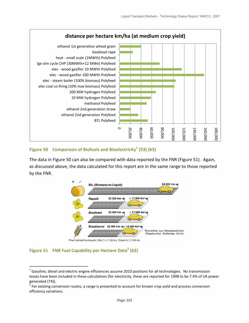
Liquid Transport Biofuels - Technology Status Report, NNFCC, 2007
Page 101
Figure 50 Comparison of Biofuels and Bioelectricity1 (53) (63)
The data in Figure 50 can also be compared with data reported by the FNR (Figure 51). Again,
as discussed above, the data calculated for this report are in the same range to those reported
by the FNR.
Figure 51 FNR Fuel Capability per Hectare Data2 (62)
1 Gasoline, diesel and electric engine efficiencies assume 2010 positions for all technologies. No transmission
losses have been included in these calculations (for electricity, these are reported for 1998 to be 7.4% of UK power generated (74)). 2 For existing conversion routes, a range is presented to account for known crop yield and process conversion
efficiency variations.
0 20
,00
0
40
,00
0
60
,00
0
80
,00
0
10
0,0
00
12
0,0
00
14
0,0
00
16
0,0
00
18
0,0
00
BTL Polyfeed
ethanol 2nd generation Polyfeed
ethanol 2nd generation straw
methanol Polyfeed
10 MW hydrogen Polyfeed
200 MW hydrogen Polyfeed
elec coal co-firing (10% max biomass) Polyfeed
elec - steam boiler (100% biomass) Polyfeed
elec - wood gasifier 200 MWth Polyfeed
elec - wood gasifier 10 MWth Polyfeed
lge stm cycle CHP (30MWth+12 MWe) Polyfeed
heat - small scale (1MWth) Polyfeed
biodiesel rape
ethanol 1st generation wheat grain
distance per hectare km/ha (at medium crop yield)

Liquid Transport Biofuels - Technology Status Report, NNFCC, 2007
Page 102
The data presented in this section indicate that, amongst the biofuel technologies, the
lignocellulosic routes (second generation) do, on the whole, produce more biofuel energy per
hectare of land, especially in the cases of synthetic diesel produced via the Fischer-Tropsch
route (BTL), methanol and hydrogen. Straw is an exception but this is an agricultural byproduct
– if the whole crop were to be used then the yield of biofuel energy per hectare would be
similar to that for BTL.
By considering just the energy produced does not, however, take into account the relative
efficiencies of converting the fuel or electricity into useful work (for example, forward motion in
a vehicle). Taking into account vehicle conversion efficiencies indicates that, if electric vehicles
as effective as today’s diesel and petrol cars were available, electric vehicles, powered by
electricity generated by advanced biomass power stations, especially those in which the waste
heat can be used (ie CHP), would provide the most effective use of biomass for road transport.
However, such vehicles, equivalent in performance and effectiveness to today’s family saloons
(Ford Mondeo or Vauxhall Vectra for example) are not currently available and would not be
expected to be so until perhaps at least the 2050 timescale (71), as illustrated by Figure 52.
Although some electric vehicles are available today, high cost, modest range, excessive
recharging times and lack of recharging facilities essentially limit their use to niche areas such as
return to base fleets and all major vehicle manufacturers have discontinued commercial
production (although some specialised manufacturers continue in production) (63). Plug in
hybrid vehicles using existing fuels containing biofuels, which provide the benefits of pure
electric vehicles (quiet operation, zero local pollution, fast acceleration etc) combined with the
range and refueling ease of today’s vehicles, are not expected to be in wide scale use until at
least 2030 and would be expected to appear commercially in advance of full electric vehicles (6)
(71). Additionally, it must be noted that the UK’s power generation capacity would need to be
expanded (via low and zero carbon technologies) to accommodate a switch in transport fuels to
electric vehicles – E4Tech estimate that the additional electricity that would be required to
supply the 2004 transport demand from cars and taxis if they were replaced with electric
vehicles would be about 16% of the 2007 UK electricity demand.
Biofuels, therefore, provide the only near and medium term, fuel based option to decarbonise
the transport sector. In the long term, should road transport become dominated by electrically
powered vehicles, liquid biofuels will remain necessary for the decarbonisation of the aviation
sector – this will become especially important as oil supplies become scarcer and should more
use be made of coal to liquids technologies to provide transport fuels.
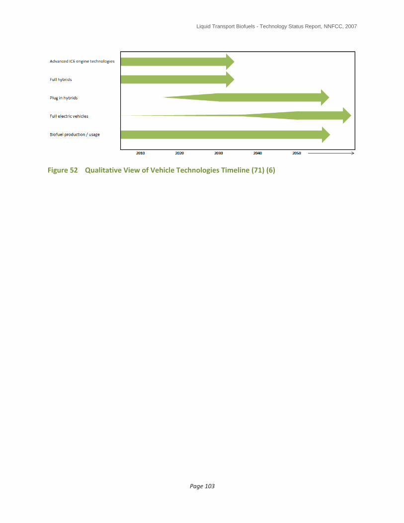
Liquid Transport Biofuels - Technology Status Report, NNFCC, 2007
Page 103
Figure 52 Qualitative View of Vehicle Technologies Timeline (71) (6)

Liquid Transport Biofuels - Technology Status Report, NNFCC, 2007
Page 104
8.0 SUMMARY
Biofuels and Bioenergy are developing rapidly and are becoming an important and large
business area. First generation processes such as the FAME biodiesel process and the
starch/sugar to ethanol processes are established across the world. In the UK, there is now
about 500,000 tonnes/year of biodiesel installed capacity and the first 55,000 tonnes/year of
bioethanol capacity started production in September 2007.
There is a number of emerging liquid biofuel technologies, most of which use lignocellulosic
materials as a feedstock. The use of biomass is important as it is unlikely that the 10% by
energy EU biofuel target can be met by sustainable supplies of first generation biofuels. The
use of biomass permits more efficient use of land resources and crops, allows feedstock to be
grown on lower quality land and potentially provides superior greenhouse gas savings
compared to first generation processes.
The following technologies have been reviewed in this report:
Biological and chemical processes o Lignocellulosic ethanol o Butanol o Furanics
Thermochemical processes o Vegetable oil hydrogenation o Pyrolysis o Biomass to liquids via syngas
8.1 Biological and Chemical Processes
Of the advanced fermentation processes, most work across the world is focused on the
production of ethanol from lignocellulosic biomass. This technology should be considered to be
entering the demonstration scale stage. Much of the ongoing work is in the USA. Technology
development requirements include:
Improve feedstock quality (more digestible crops and crops with reduced 5-carbon sugar content)
Improve pretreatments (ie reduce chemical and heat inputs by using novel biochemical and chemical approaches)
Improve enzymes (ie these need to be made cheaper and more efficient)
Improve fermentation (ie more robust organisms are required especially in the area of 5-carbon sugar fermentation).
Butanol development is attractive as this fuel is more easily incorporated into our existing fuels
infrastructure. In the UK, BP and Green Biologics are leading on biobutanol development. It
Liquid Transport Biofuels - Technology Status Report, NNFCC, 2007
Page 105
would be expected that butanol production should commence in the early 2010’s. Furanics are
still being developed at lab scale so are perhaps further away in terms of commercialisation.
8.2 Thermochemical Processes
Of the thermochemical routes discussed in this report, vegetable oil hydrogenation is the most
advanced with Neste having started commercial operations at their Porvoo oil refinery in
Finland in September 2007. However, this process still requires the use of vegetable oil
feedstocks although developers are actively researching the potential for non edible oils such as
Jatropha and, in particular, algal oils which may provide a route to significant sustainable scale
up of this process route.
Pyrolysis is the cheapest biomass process route in terms of capital cost but produces the most
difficult product to integrate directly into the transport fuel pool. It is developing and will
develop for heat and power applications in the nearer term. However, research is ongoing (eg
UOP) to upgrade the bio-oil so that it can be used as an oil refinery feedstock and to extract
valuable chemicals (Aston University/CARE Ltd). If fed to an oil refinery for upgrading, the
bio-fraction of the refinery feedstock would end up in the range of refinery products from
refinery fuel gas to mid distillates. Probably most advanced in terms of commercialisation is
Canadian company Dynamotive who have constructed a 70,000 tonnes/year plant in Ontario.
Processes which use syngas as an intermediate product (eg BTL) produce the most easily
integrated final fuels (eg synthetic diesel, aviation fuel, naphtha) but are the most expensive to
build. Most advanced at present are Choren in Germany who are about to start operations at
their 15,000 tonnes/year syndiesel plant in Freiberg, Germany with five 200,000 tonnes/year
plants planned for construction in the early 2010’s and Range Fuels in Georgia, USA who have
recently just started building a 113,000 tonnes/year syngas to ethanol.
8.3 UK Future Direction
Biofuels provide the only near and medium term, fuel based option to decarbonise the
transport sector. They also provide the potential to co-produce energy, renewable chemicals
and materials. In the long term (+2050 timescale), should electric vehicles develop sufficiently
to result in road transport becoming dominated by electric power, liquid biofuels will remain
necessary for the decarbonisation of other sectors where high specific power outputs are
required including aviation and agriculture for example – this will become especially important
as oil supplies become scarcer. Therefore, although providing a lower “field to wheels” energy
effectiveness compared with electricity and heat production from biomass, biofuel
development remains important.
Liquid Transport Biofuels - Technology Status Report, NNFCC, 2007
Page 106
There are a number of advanced biofuel options being developed - none are clear front
runners, each having advantages and disadvantages.
Lignocellulosic ethanol production is possibly closer to commercial reality than the Biomass to
Liquids (BTL) via syngas route and the UK could potentially benefit by leveraging US progress in
this area. Additionally, a lignocellulosic facility could potentially more effectively share utilities
at an existing first generation ethanol production plant thereby reducing investment costs.
However, ethanol is a gasoline substitute only and, as noted above, the UK and EU fuels
markets are long on gasoline while short of diesel and aviation fuel. The potential to produce
an enhanced quality renewable synthetic diesel and/or aviation fuel via the BTL process
combined with renewable naphtha (for the production of renewable plastics for example) is
therefore attractive. The key barrier to both the lignocellulosic ethanol and BTL routes,
however, is high capital investment costs. The pyrolysis process overcomes these at the
expense of product quality – pyrolysis oil or bio-oil cannot directly be used as a transport fuel.
Research is, though, ongoing to upgrade the low quality pyrolysis oil to a range of standard
refinery products, as noted above.

Liquid Transport Biofuels - Technology Status Report, NNFCC, 2007
Page 107
WORKS CITED
1. Bown, D (AMEC). Techno-economic Evaluation of Emerging Biodiesel Production
Technologies, NNFCC ref 07/009. AMEC. s.l. : NNFCC, March 2007.
http://www.nnfcc.co.uk/metadot/index.pl?id=4040;isa=DBRow;op=show;dbview_id=2457.
2. Smith, W (Tamutech). Mapping the Development of UK Biorefinery Complexes – Literature
Review. s.l. : NNFCC, May 2007. Available from
http://www.nnfcc.co.uk/metadot/index.pl?id=4039;isa=DBRow;op=show;dbview_id=2457.
report 07/008.
3. Morgan, M (Nexant Chemsystems). Feasibility of Second Generation Biodiesel Production in
the United Kingdom. s.l. : NNFCC, May 2007.
http://www.nnfcc.co.uk/metadot/index.pl?id=4041;isa=DBRow;op=show;dbview_id=2457. .
report 07-14.
4. UK PIA. Statistical Review 2007. May 2007. available from: www.ukpia.com.
5. http://www.cfit.gov.uk/docs/2003/aec/aec/index.htm. [Online] [Cited: February 21, 2008.]
6. Raskin, Amy and Shah, Saurin. The Emergence of Hybrid Vehicles. Ending Oil’s Stranglehold
on Transportation and the Economy. s.l. : Alliance Bernstein, June 2006. available from:
http://www.calcars.org/alliance-bernstein-hybrids-june06.pdf.
7. Alice Bows, Paul Upham, Kevin Anderson. Growth Scenarios for EU and UK Aviation. s.l. :
Tyndall Centre for Climate Change Research, 16 April 2005. available from:
http://www.foe.co.uk/resource/reports/aviation_tyndall_research.pdf.
8. Realising our Vision to Become a Leader in BTL. Turpeinen, H (Neste Oil). s.l. :
www.cmtevents.com, September 12-13 2007. presented at 2nd BTLtec Conference (arranged
by Centre for Management Technology), Vienna.
9. Biotechnology Options for Bioenergy Crops. Flavell, R (Ceres Inc., Ca, USA). 20-22 August
2007. presented at USDA Global Conference on Agricultural Biofuels: Research and Economics,
Minneapolis, Minnesota.
10. “Improved Glycerine Quality via Solid Catalyst Transesterification Technology: The Esterfip-H
Process. Bloch, Michel (Axens). s.l. : Bio-Oil International Conference, Vigo, February 2006.
11. http://www.axens.net/html-gb/offer/offer_processes_104.html.php. [Online]
12. Waller, I (5barg8). Email communication (“FAME process development”). 15 Nov 2007.
www.5barg8.com..
Liquid Transport Biofuels - Technology Status Report, NNFCC, 2007
Page 108
13. The UK’s First Commercial Bioethanol Plant: Sugar Beet to Biorefinery. Bulman, A (British
Sugar). 21-22 September 2007. presented at REA 2007 Bioenergy Conference, Oxford. Available
from http://www.r-e-a.net/article_default_view.fcm?articleid=2748.
14. NNFCC. Biorefineries: Definitions, examples of current activities and suggestions for UK
development. Jan 2007. available from
http://www.nnfcc.co.uk/metadot/index.pl?id=3143;isa=DBRow;op=show;dbview_id=2457.
15. Morgan, M (Nexant Chemsystems). Private Communication to NNFCC. September 2007.
16. EIA. Alternatives to Traditional Transportation Fuels: An Overview. Energy Information
Adminstration, Office of Coal, Nuclear, Electric and Alternate Fuels, US Dept of Energy,
Washington DC. June 1994. available from:
http://tonto.eia.doe.gov/FTPROOT/alternativefuels/0585o.pdf.
17. Re-commercialising the ABE Fermentation. Green, E (Green Biologics). 4-5 October 2007.
Presented at Next Generation Biofuels Markets, Amsterdam.
http://www.greenpowerconferences.com/biofuelsmarkets/NextGeneration_download.html.
18. http://uk.reuters.com/article/topNews/idUKMOL16678120071121. [Online]
19. Next Generation Biofuel Markets. Riva, C A (Verenium). 4-5 October 2007. Presented at
Next Generation Biofuels Markets, Amsterdam.
http://www.greenpowerconferences.com/biofuelsmarkets/NextGeneration_download.html.
20. http://www.rbj.net/fullarticle.cfm?sdid=69441 . [Online]
21. http://www.nile-bioethanol.org/ . [Online]
22. Reuters News. http://www.reuters.com/article/mergersNews/idUSWLA247820071106.
[Online]
23. Making Cellulose Ethanol a Reality. Bemer, G (Royal Nedalco). 4-5 October 2007. Presented
at Next Generation Biofuels Markets, Amsterdam.
http://www.greenpowerconferences.com/biofuelsmarkets/NextGeneration_download.html.
24. Fish, S (IGER). Private Communication. 26 Nov 2007. www.iger.bbsrc.ac.uk.
25. Oxley, J (BP). Private communication to G Evans. 18th Nov 2007.
26. Biopact. http://biopact.com/2007/10/avantium-tests-new-generation-of-high.html.
[Online]
Liquid Transport Biofuels - Technology Status Report, NNFCC, 2007
Page 109
27. Neste Oil. Answering the Rernewable Fuel Challenge. Available from
http://akseli.tekes.fi/opencms/opencms/OhjelmaPortaali/ohjelmat/ClimBus/en/Dokumenttiarki
sto/Viestinta_ja_aktivointi/Esitysaineisto/Projektiaineistot/NExBTL_European_version.pdf.
[Online] undated.
28. Erametsa, H (Neste Oil). Neste Oil’s NExBTL Renewable Diesel. m
http://bioenergy.ucdavis.edu/materials/Presentations/Neste_NExBTL%20CA%20Dec2006.pdf.
[Online] October 18, 2006.
29. Creating a Sustainable Biofuels Infrastructure. Holmgren, J (UOP). 4-5 October 2007.
Presented at Next Generation Biofuels Markets, Amsterdam.
http://www.greenpowerconferences.com/biofuelsmarkets/NextGeneration_download.html.
30. http://www.biodieselnow.com/forums/p/15680/120923.aspx . [Online]
31. Vigue, J-C (IFP). private email communication to G Evans. 7th Nov 2007.
32. Overview. Waste Plastics to Diesel Fuel. Innovative Environmental Technology.
http://envosmart.com/2006/uploadedfiles/envofuel_summary.pdf. [Online] [Cited: February
11, 2008.]
33. Realisation of the Bioslurry Gasification Concept. Dahmen, N (FZK). 2007. Presented at 2nd
BTLtec conference Vienna. www.cmtevents.com.
34. Catalytic Pyrolysis of Biomass for the Production of Green Oil. Brem, G (TNO). 12-13
September 2007. presented at presented at 2nd BTLtec Conference (arranged by Centre for
Management Technology), Vienna. www.cmtevents.com.
35. http://pubs.acs.org/cen/news/85/i16/8516news7.html. [Online] [Cited: January 24, 2008.]
36. Brown, R C and Holmgren, J. Fast Pyrolysis and Bio-Oil Upgrading. s.l. : Iowa State
University/UOP. available from:
http://www.ars.usda.gov/sp2UserFiles/Program/307/biomasstoDiesel/RobertBrown&JenniferH
olmgrenpresentationslides.pdf.
37. Peacocke, C (CARE Ltd). private email communication to G Evans “Pyrolysis Liquids”.
October 31, 2007.
38. Berkel, Arij van. Implementing Second Generation Biofuels. s.l. : Europoint, 10 January 2008.
available from: http://conference.europoint.eu/biofuels2008/.

Liquid Transport Biofuels - Technology Status Report, NNFCC, 2007
Page 110
39. Biomass Conversion: A Sustainable Path to Clean Renewable Energy, Fuels and Chemicals.
Van Der Meij, (BIOeCON). 12-13 September 2007. presented at 2nd BTLtec conference Vienna.
www.cmtevents.com.
40. Pyrolysis and Gasification: UK Industry and Operational Plants. Peacocke, C (CARE Ltd). Feb
2007. UK Trade and Investment EISU Mission to the Far East. . www.care.demon.co.uk.
41. http://www.industryweek.com/ReadArticle.aspx?ArticleID=15726. [Online] [Cited: February
7, 2008.]
42. http://www.startech.net/plasma.html . [Online]
43.
http://www.gasification.org/Docs/Legis/2007%20China%20Roundtable/Senate%20RT%20Revie
w%20DOW%20JPH%202007%2003%2023.pdf. [Online]
44. Production of Fischer-Tropsch Products in a Slip-Stream of Large Coal Fired Power Stations.
Zwart, R (ECN). 12-13 September 2007. presented at 2nd BTLtec conference Vienna.
www.cmtevents.com.
45. BTL/XTL: Advantages and Hurdles. Vigue, J-C (IFP). 23-26 April 2007. presented at 7th World
GTL Summit, London. www.thecwcgroup.com.
46. Fischer-Tropsch Synthesis. Oukaci, R (Energy Technology Partners). 23rd April 2007.
presented at 7th World GTL Conference. www.thecwcgroup.com.
47. The Thermochemical Route to Second Generation Biofuels. Deutmeyer, M (Choren
Industries). 1-2 November 2007. NNFCC Green Supply Chain Conference 2007, York.
48. The CHRISGAS Project -Syngas from Biomass. Gårdmark, L (Marketing VVBGC ). 12-13
September 2007. presented at 2nd BTLtec Conference (arranged by Centre for Management
Technology). www.cmtevents.com.
49. Project Status and Commercialisation Prospects of the Gussing BTL Project. Repfel-Nitsche,
K (Vienna University of Technology). 12-13 September 2007. presented at 2nd BTLtec
Conference (arranged by Centre for Management Technology), Vienna. www.cmtevents.
50. Forest Industry and 2G Biofuels. Sohlstrom, H. Harrington Hall Hotel, London : Marcus
Evans, 1 Feb 2008. presented at: BIOFUELS FORUM: EVALUATING AND IMPLEMENTATING
FUTURE BUSINESS OPPORTUNITIES. www.marcusevans.com.

Liquid Transport Biofuels - Technology Status Report, NNFCC, 2007
Page 111
51.
http://www.nytimes.com/2007/11/09/business/09fuel.html?_r=2&pagewanted=1&oref=slogin
. [Online]
52. http://www.lanzatech.co.nz/ . [Online]
53. Well-to-Wheels Analysis of Future Automotive Fuels and Powertrains in the European
Context. Concawe/Eucar/JRC. March 2007. http://ies.jrc.cec.eu.int/wtw.html. Version 2c.
54. http://www.berr.gov.uk/files/file39390.pdf . [Online]
55. Harrison, Harrison, P (The Business Project Office). Commercial Opportunity for a 1MT
Biomass to Liquids Facility in the UK by 2020. On behalf of North East Biofuels. August 200.
56. Global Watch Mission Report: Second Generation Transport Biofuels - a Mission to the
Netherlands, Germany and Finland. DTI. s.l. : DTI/NNFCC, March 2006. Available from
http://www.oti.globalwatchonline.com/online_pdfs/36610MR.pdf.
57. Comparative economics of biorefineries based on the biochemical and thermochemical
platforms. Wright, MM and Brown, RC. s.l. : Biofuels, Bioprod. Bioref, 1:49-56. , Sept 2007.
58. GTL Project Challenges in Today’s EPC Market. Rettenmaier, A (Black & Veatch). 23-26 April
2007. presented at 7th World GTL Summit, London. www.thecwcgroup.com.
59. Applicability of Hydrogenated Palm Oil for Automotive Fuels. Koyama, Akira, Iki, Hideshi
and Iguchi, Yasutoshi. 5-6 November 2006. 16th Saudi Arabia-Japan Joint Symposium, Dahran,
Saudi Arabia. http://www.kfupm.edu.sa/catsymp/Symp16th/PDF%20Papers/05koyama.pdf.
60. UK Biomass Strategy. s.l. : Defra, May 2007. available from:
http://www.defra.gov.uk/Environment/climatechange/uk/energy/renewablefuel/pdf/ukbioma
ssstrategy-0507.pdf.
61. Defra. UK Biomass Strategy. May 2007. available from:
www.defra.gov.uk/environment/climatechange/uk/energy/renewablefuel/pdf/ukbiomassstrat
egy-0507.pdf.
62. Fachagentur Nachwachsende Rohstoffe e. V. (FNR). Biofuels: Plants Raw Materials
Products. Hofplatz 1, 18276 Gülzow, Germany : Fachagentur Nachwachsende Rohstoffe e.V.
(FNR), 2006. available from: http://www.fnr-
server.de/pdf/literatur/pdf_230biokraftstoff_engl_2006.pdf.

Liquid Transport Biofuels - Technology Status Report, NNFCC, 2007
Page 112
63. E4Tech. A Review of the UK Innovation System for Low Carbon Road Transport Technologies.
London : UK Department for Transport, March 2007. available from:
http://www.dft.gov.uk/pgr/scienceresearch/technology/lctis/e4techlcpdf.
64. http://www.vt.tuwien.ac.at/biobib/biobib.html. [Online] [Cited: February 10, 2008.]
65. Royal Commision on Environmental Pollution. Biomass as a Renewable Energy Source.
2004. available from: http://www.my-
energy.org.uk/MY/Library2.nsf/ab283684d03f231d80256b520047d321/6E23DC0C05270B0480
25736200535308/$file/RCEP%20-
%20biomass%20as%20a%20renewable%20energy%20source.pdf.
66. www.nnfcc.co.uk. [Online]
67. http://www.nnfcc.co.uk/metadot/index.pl?id=4227;isa=DBRow;op=show;dbview_id=2539.
[Online] [Cited: February 10, 2008.]
68. Spink, John. Sector Head Crop Physiology, ADAS. [interv.] Geraint Evans. February 12, 2008.
69. Khokhotva, Oleksandr. “Optimal” use of biomass for energy in Europe:Consideration based
upon the value of biomass for CO2 emission reduction. Lund, Sweden : The International
Institute for Industrial Environmental Economics, 2004. available from:
http://svebio.agriprim.com/attachments/33/95.pdf. ISSN 1401-9191.
70. Opdal, Olav A. Production of synthetic biodiesel via Fischer-Tropsch. s.l. : Department of
Energy & Process engineering, Norwegian University of Science and Technology, December
2006. available from: http://www.zero.no/transport/bio/BtL%20Namdalen.pdf.
71. King, J. The King Review of Low-Carbon Cars. 7 November 2007. Available from:
http://www.lowcvp.org.uk/assets/presentations/Julia%20King.pdf.
72. http://www.reuters.com/article/mergersNews/idUSWLA247820071106. [Online]
73. http://www.greencarcongress.com/2007/09/conocophillips-.html. [Online]
74. www.powerwatch.org.uk/energy/graham.asp. [Online] [Cited: February 23, 2008.]
75. DTI (BERR). UK Biomass Strategy 2007. Working Paper 1 - Economic Anaylsis of Biomass
Energy. s.l. : DTI (BERR), May 2007. available from: http://www.berr.gov.uk/files/file39040.pdf.
URN 07/950.
76. DBerr. Publication URN 08/P2. 2005.

Liquid Transport Biofuels - Technology Status Report, NNFCC, 2007
Page 113
77. Bergman, P and Kiel, J. Torrefaction for Biomass Upgrading. ECN. November 2005.
www.ecn.nl/biomass. ECN-RX--05-180.
78. Ringer, M and Putsche, V and Scahill, J. Large Scale Pyrolysis Oil Production: A Technology
Assessment and Economic Analysis. s.l. : NREL, November 2006. available from:
http://www.nrel.gov/docs/fy07osti/37779.pdf. NREL/TP-510-37779.
79. Bradley, D. European Market Study for BioOil (Pyrolysis Oil). 15 December 2006. available
from:
http://www.bioenergytrade.org/downloads/bradleyeuropeanbiooilmarketstudyfinaldec15.pdf.
80. BERR. Quarterly Energy Prices. BERR. December 2007. available from:
http://www.berr.gov.uk/files/file43302.pdf. URN 07/276d.

Liquid Transport Biofuels - Technology Status Report, NNFCC, 2007
Page 114
Appendices

Liquid Transport Biofuels - Technology Status Report, NNFCC, 2007
Page 115
APPENDIX 1 – MINDMAPS
These mindmaps provide a summary of most of the technologies reviewed in this report. A detailed set of mindmaps are available separately.

Liquid Transport Biofuels - Technology Status Report, NNFCC, 2007
Page 116
FAME Summary Mindmap

Liquid Transport Biofuels - Technology Status Report, NNFCC, 2007
Page 117
First Generation Ethanol Summary Mindmap

Liquid Transport Biofuels - Technology Status Report, NNFCC, 2007
Page 118
Lignocellulosic Ethanol (Biological) Summary Mindmap

Liquid Transport Biofuels - Technology Status Report, NNFCC, 2007
Page 119
Furanics Mindmap

Liquid Transport Biofuels - Technology Status Report, NNFCC, 2007
Page 120
Vegetable Oil Hydrogenation Summary Mindmap

Liquid Transport Biofuels - Technology Status Report, NNFCC, 2007
Page 121
Pyrolysis Summary Mindmap
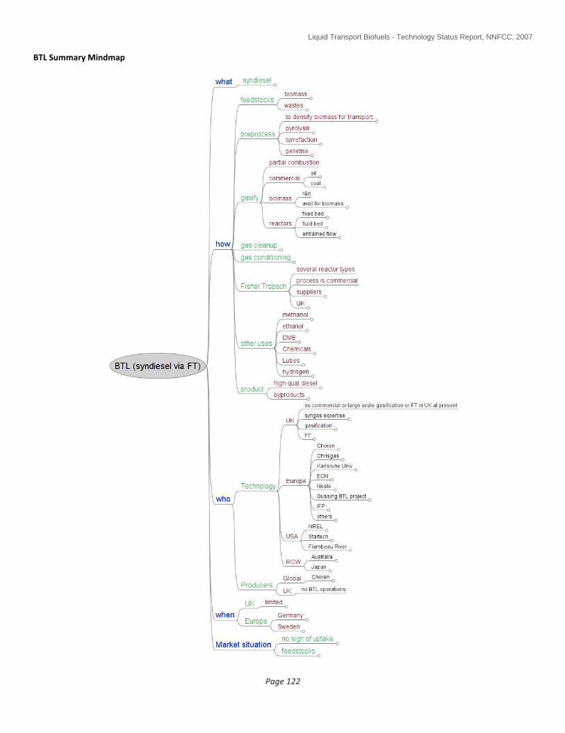
Liquid Transport Biofuels - Technology Status Report, NNFCC, 2007
Page 122
BTL Summary Mindmap

Liquid Transport Biofuels - Technology Status Report, NNFCC, 2007
Page 123
APPENDIX 2 – SUMMARY OF BIOFUEL PROPERTIES

Liquid Transport Biofuels - Technology Status Report, NNFCC, 2007
Page 124
APPENDIX 3 - OPPORTUNITIES, DRIVERS, BARRIERS/STATUS AND UK ACTIVITY TABLES (2)
The attached tables provide a overview of gaps and barriers and what research is ongoing in the UK.
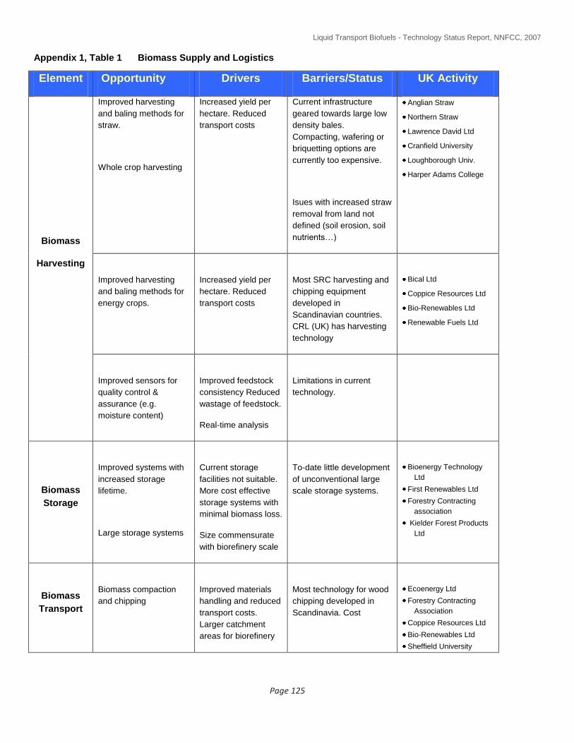
Liquid Transport Biofuels - Technology Status Report, NNFCC, 2007
Page 125
Appendix 1, Table 1 Biomass Supply and Logistics
Element Opportunity Drivers Barriers/Status UK Activity
Biomass
Harvesting
Improved harvesting
and baling methods for
straw.
Whole crop harvesting
Increased yield per
hectare. Reduced
transport costs
Current infrastructure
geared towards large low
density bales.
Compacting, wafering or
briquetting options are
currently too expensive.
Isues with increased straw
removal from land not
defined (soil erosion, soil
nutrients…)
Anglian Straw
Northern Straw
Lawrence David Ltd
Cranfield University
Loughborough Univ.
Harper Adams College
Improved harvesting
and baling methods for
energy crops.
Increased yield per
hectare. Reduced
transport costs
Most SRC harvesting and
chipping equipment
developed in
Scandinavian countries.
CRL (UK) has harvesting
technology
Bical Ltd
Coppice Resources Ltd
Bio-Renewables Ltd
Renewable Fuels Ltd
Improved sensors for
quality control &
assurance (e.g.
moisture content)
Improved feedstock
consistency Reduced
wastage of feedstock.
Real-time analysis
Limitations in current
technology.
Biomass
Storage
Improved systems with
increased storage
lifetime.
Large storage systems
Current storage
facilities not suitable.
More cost effective
storage systems with
minimal biomass loss.
Size commensurate
with biorefinery scale
To-date little development
of unconventional large
scale storage systems.
Bioenergy Technology
Ltd
First Renewables Ltd
Forestry Contracting
association
Kielder Forest Products
Ltd
Biomass
Transport
Biomass compaction
and chipping
Improved materials
handling and reduced
transport costs.
Larger catchment
areas for biorefinery
Most technology for wood
chipping developed in
Scandinavia. Cost
Ecoenergy Ltd
Forestry Contracting
Association
Coppice Resources Ltd
Bio-Renewables Ltd
Sheffield University

Liquid Transport Biofuels - Technology Status Report, NNFCC, 2007
Page 126
Element Opportunity Drivers Barriers/Status UK Activity
Modelling
Tools
New tools for analysing
and optimising of
complex biomass
supply systems
More efficient
biomass supply
chains. Assist in
strategic planning &
coordination of R&D
activities.
Models in early stage of
development. Oak Ridge
National Laboratory (US)
and Wageningen
University (NL) have well
developed systems.
ADAS
Cranfield University
Imperial College
TSEC-BIOSYS activity
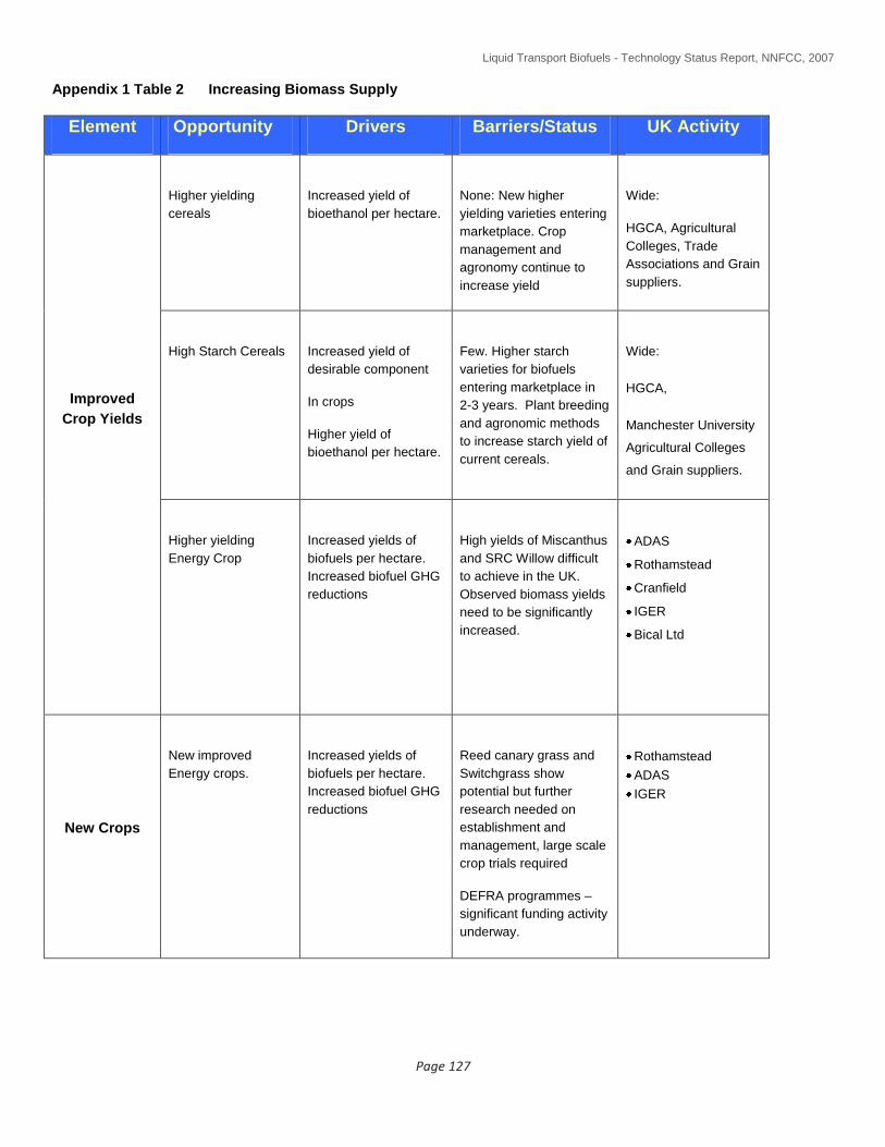
Liquid Transport Biofuels - Technology Status Report, NNFCC, 2007
Page 127
Appendix 1 Table 2 Increasing Biomass Supply
Element Opportunity Drivers Barriers/Status UK Activity
Improved
Crop Yields
Higher yielding
cereals
Increased yield of
bioethanol per hectare.
None: New higher
yielding varieties entering
marketplace. Crop
management and
agronomy continue to
increase yield
Wide:
HGCA, Agricultural
Colleges, Trade
Associations and Grain
suppliers.
High Starch Cereals
Increased yield of
desirable component
In crops
Higher yield of
bioethanol per hectare.
Few. Higher starch
varieties for biofuels
entering marketplace in
2-3 years. Plant breeding
and agronomic methods
to increase starch yield of
current cereals.
Wide:
HGCA,
Manchester University
Agricultural Colleges
and Grain suppliers.
Higher yielding
Energy Crop
Increased yields of
biofuels per hectare.
Increased biofuel GHG
reductions
High yields of Miscanthus
and SRC Willow difficult
to achieve in the UK.
Observed biomass yields
need to be significantly
increased.
ADAS
Rothamstead
Cranfield
IGER
Bical Ltd
New Crops
New improved
Energy crops.
Increased yields of
biofuels per hectare.
Increased biofuel GHG
reductions
Reed canary grass and
Switchgrass show
potential but further
research needed on
establishment and
management, large scale
crop trials required
DEFRA programmes –
significant funding activity
underway.
Rothamstead
ADAS
IGER

Liquid Transport Biofuels - Technology Status Report, NNFCC, 2007
Page 128
Element Opportunity Drivers Barriers/Status UK Activity
Biotechnology
Exploit advances in
biotechnology such
as genomics, marker
assisted breeding
and genetic
engineering to
deliver improved
biomass feedstocks
Crops with higher
yields, higher tolerance
and reduces agronomic
inputs.
Crops with tailored
compositions to have
increased levels of
desirable component
(ie increased starch )
Incorporate attractive
plant traits for
downstream biorefinery
processing
(less lignin, reduced
recalcitrance…)
Plant factories: crops
with high value
constituents co-
production high value
chemicals
More detailed
fundamental
understanding required
along with analytical
capability
Public resistance to
genetically modified crops
Potential negative
impacts on environment
and biodiversity need
clarification.
Long term planning
required
UK recognised as
being world class in
plant science and plant
genetics –many
centres of expertise
Marine
Biomass
Exploit untapped
seaweed biomass
reserves around UK
coastline
New potentially highly
productive biomass
resource that doesn’t
compete for limited
land.
Harvested only on small
scale for food. Limited
information on potential
as a biomass resource for
energy or fuels but some
activity in Japan, Norway
and US.
Scottish Association
for Marine Science
Micro algae
Untapped biomass
resource for both
vegetable oils and
biomass.
New source of high
yielding resource for
biomass & veg oils
(biodiesel) . Micro
algae demonstrate
extremely high
photosynthetic
efficiency & growth
No commercial
demonstration. Small
number of companies
developing micro algae
technology in US, SA, NL
and Israel. Fast growth
requires photobioreactor
development.
Next Generation
University of the West
of England
Appendix 1 Table 3 Fermentation Routes to Lignocellulosic Ethanol
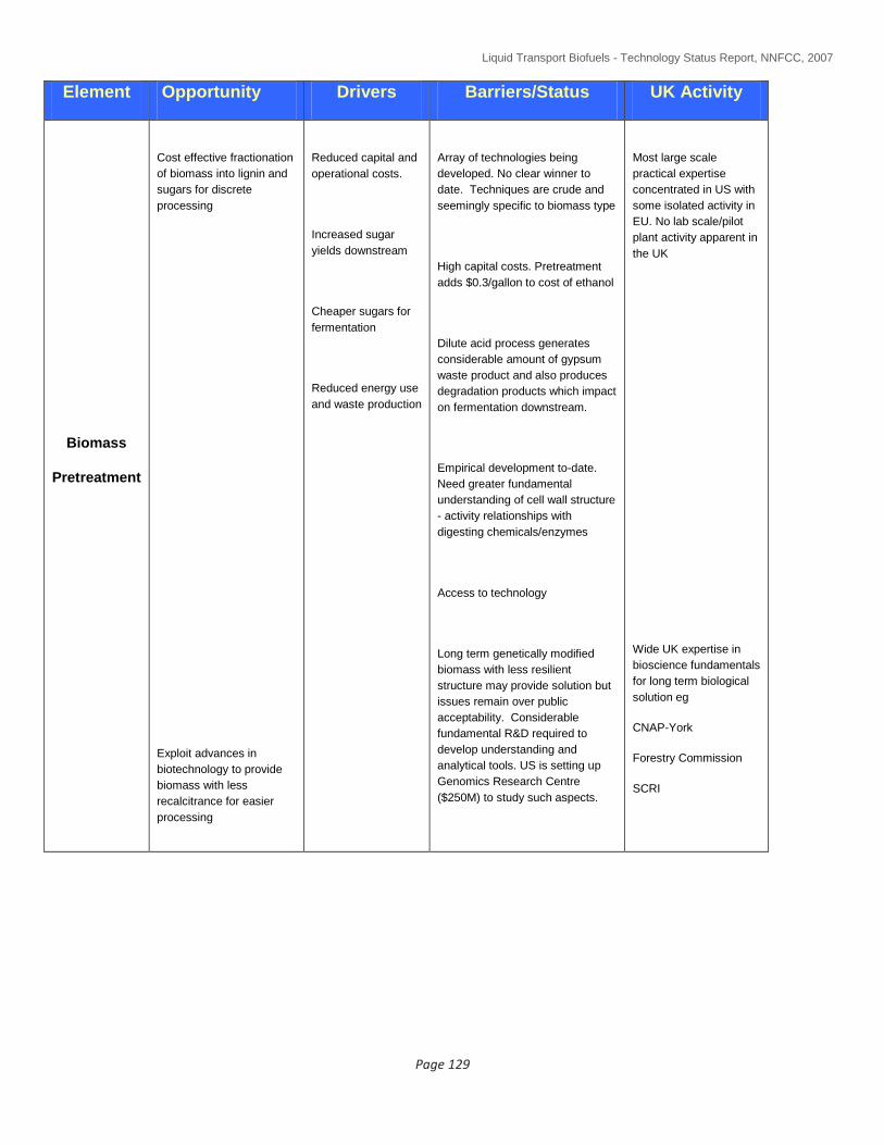
Liquid Transport Biofuels - Technology Status Report, NNFCC, 2007
Page 129
Element Opportunity Drivers Barriers/Status UK Activity
Biomass
Pretreatment
Cost effective fractionation
of biomass into lignin and
sugars for discrete
processing
Exploit advances in
biotechnology to provide
biomass with less
recalcitrance for easier
processing
Reduced capital and
operational costs.
Increased sugar
yields downstream
Cheaper sugars for
fermentation
Reduced energy use
and waste production
Array of technologies being
developed. No clear winner to
date. Techniques are crude and
seemingly specific to biomass type
High capital costs. Pretreatment
adds $0.3/gallon to cost of ethanol
Dilute acid process generates
considerable amount of gypsum
waste product and also produces
degradation products which impact
on fermentation downstream.
Empirical development to-date.
Need greater fundamental
understanding of cell wall structure
- activity relationships with
digesting chemicals/enzymes
Access to technology
Long term genetically modified
biomass with less resilient
structure may provide solution but
issues remain over public
acceptability. Considerable
fundamental R&D required to
develop understanding and
analytical tools. US is setting up
Genomics Research Centre
($250M) to study such aspects.
Most large scale
practical expertise
concentrated in US with
some isolated activity in
EU. No lab scale/pilot
plant activity apparent in
the UK
Wide UK expertise in
bioscience fundamentals
for long term biological
solution eg
CNAP-York
Forestry Commission
SCRI
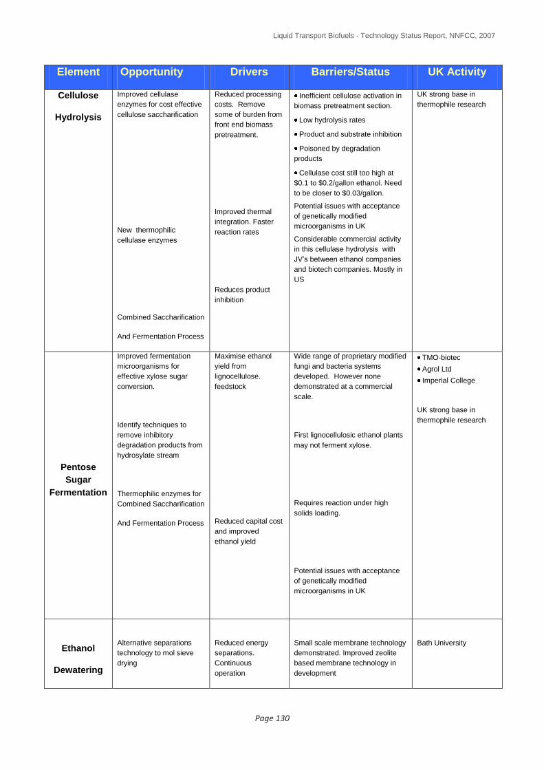
Liquid Transport Biofuels - Technology Status Report, NNFCC, 2007
Page 130
Element Opportunity Drivers Barriers/Status UK Activity
Cellulose
Hydrolysis
Improved cellulase
enzymes for cost effective
cellulose saccharification
New thermophilic
cellulase enzymes
Combined Saccharification
And Fermentation Process
Reduced processing
costs. Remove
some of burden from
front end biomass
pretreatment.
Improved thermal
integration. Faster
reaction rates
Reduces product
inhibition
Inefficient cellulose activation in
biomass pretreatment section.
Low hydrolysis rates
Product and substrate inhibition
Poisoned by degradation
products
Cellulase cost still too high at
$0.1 to $0.2/gallon ethanol. Need
to be closer to $0.03/gallon.
Potential issues with acceptance
of genetically modified
microorganisms in UK
Considerable commercial activity
in this cellulase hydrolysis with
JV’s between ethanol companies
and biotech companies. Mostly in
US
UK strong base in
thermophile research
Pentose
Sugar
Fermentation
Improved fermentation
microorganisms for
effective xylose sugar
conversion.
Identify techniques to
remove inhibitory
degradation products from
hydrosylate stream
Thermophilic enzymes for
Combined Saccharification
And Fermentation Process
Maximise ethanol
yield from
lignocellulose.
feedstock
Reduced capital cost
and improved
ethanol yield
Wide range of proprietary modified
fungi and bacteria systems
developed. However none
demonstrated at a commercial
scale.
First lignocellulosic ethanol plants
may not ferment xylose.
Requires reaction under high
solids loading.
Potential issues with acceptance
of genetically modified
microorganisms in UK
TMO-biotec
Agrol Ltd
Imperial College
UK strong base in
thermophile research
Ethanol
Dewatering
Alternative separations
technology to mol sieve
drying
Reduced energy
separations.
Continuous
operation
Small scale membrane technology
demonstrated. Improved zeolite
based membrane technology in
development
Bath University

Liquid Transport Biofuels - Technology Status Report, NNFCC, 2007
Page 131
Appendix 1 Table 4 Thermochemical Routes for Conversion of Biomass to Synthetic Diesel and
other Potential Biofuels
Element Opportunity Drivers Barriers/Status UK Activity
Biomass
Drying
Cost effective drying of
biomass prior to
processing. Moisture
contents of biomass
reduced from 50wt%%
down to 10-15wt%
Optimise
performance in
downstream
gasification
Energy costs
reduced through
effective thermal
integration with
downstream
operations.
Requires pilot plant study and
modelling tools
Biomass
Pyrolysis
Cost effective production
of bio-oil through
optimisation of fast
pyrolysis techniques.
Easily transportable
liquid biomass
feedstock to facilitate
development of long
distance supply
chains.
Biomass feedstock
with greatly reduced
materials handling
issues that can be
integrated with
existing feed
systems on
conventional
gasifiers
Fundamentals of bio-oil
formation and chemistry not
well understood
A number of different reactor
designs being pursued.
Char separation difficult
Bio-oil phase separation
problematic
Bio-oil properties vary with
biomass feedstock
Pyrolysis techniques nearing
commercialisation for waste to
energy systems. Fast pyrolsis pilot
plant developments at a number of
European centres inc UK
Aston University
Supergen
Consortium
Wellman Process
Engineering
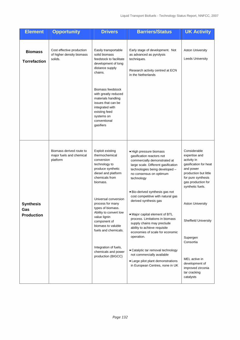
Liquid Transport Biofuels - Technology Status Report, NNFCC, 2007
Page 132
Element Opportunity Drivers Barriers/Status UK Activity
Biomass
Torrefaction
Cost effective production
of higher density biomass
solids.
Easily transportable
solid biomass
feedstock to facilitate
development of long
distance supply
chains.
Biomass feedstock
with greatly reduced
materials handling
issues that can be
integrated with
existing feed
systems on
conventional
gasifiers
Early stage of development. Not
as advanced as pyrolysis
techniques.
Research activity centred at ECN
in the Netherlands
Aston University
Leeds University
Synthesis
Gas
Production
Biomass derived route to
major fuels and chemical
platform
Exploit existing
thermochemical
conversion
technology to
produce synthetic
diesel and platform
chemicals from
biomass.
Universal conversion
process for many
types of biomass.
Ability to convert low
value lignin
component of
biomass to valuble
fuels and chemicals.
Integration of fuels,
chemicals and power
production (BIGCC)
High pressure biomass
gasification reactors not
commercially demonstrated at
large scale. Different gasification
technologies being developed –
no consensus on optimum
technology
Bio-derived synthesis gas not
cost competitive with natural gas
derived synthesis gas
Major capital element of BTL
process. Limitations in biomass
supply chains may preclude
ability to achieve requisite
economies of scale for economic
operation.
Catalytic tar removal technology
not commercially available
Large pilot plant demonstrations
in European Centres, none in UK
Considerable
expertise and
activity in
gasification for heat
and power
production but little
for pure synthesis
gas production for
synthetic fuels.
Aston University
Sheffield University
Supergen
Consortia
MEL active in
development of
improved zirconia
tar cracking
catalysts

Liquid Transport Biofuels - Technology Status Report, NNFCC, 2007
Page 133
Element Opportunity Drivers Barriers/Status UK Activity
Fischer
Tropsch
Process
Synthetic diesel fuels
compatible with existing
engines and derived from
biomass
2nd
generation
biofuel with improved
GHG reductions over
conventional
biodiesel
Integration of fuels
and power
production with
cogeneration (once
through) concepts
Little in the way of technical
barriers – process technology
established.
Catalyst selectivity to diesel range
products could be improved but
will require radical step-out in
performance (unlikely in short to
medium term)
Huge capital costs. Difficult to
achieve economy of scale due to
feedstock supply limitations
All major oil,
engineering and
catalyst companies
developing FT
systems (gas and
coal).
FT catalyst
fundamentals:
Oxford University
No specific activity
apparent on
bioderived
synthesis gas as
feedstock
Other
Biofuels
from
Synthesis
Gas
Alternative biofuels with
improved performance and
higher GHG reductions
Exploit large
gasification complex
to produce range of
value added co-
products in addition
to synthetic diesel.
Cost effective
competition to
conventional sugar
fermentation routes
to bioethanol and
platform chemicals.
Heterogeneous catalyst
technology not optimal for
selective production of mixed
alcohols or ethanol from synthesis
gas.
Difficult to compete against huge
megamethanol plants utilising
natural gas.
Fermentation technology holds
promise for ethanol production
form synthesis gas but still at
development stage
Catalyst
development
activity for mixed
alcohols and
improved
methanol systems
– not specifically
for bioderived
synthesis gas:
Imperial College
Cardiff University
Glasgow
University