Embed Size (px)
Citation preview
______________________________________________________________________________
INTERNAL SPLINT FOR FRACTURE FIXATION IN CANINES
A Major Qualifying Project Report
Submitted to the Faculty of Worcester Polytechnic Institute
In Partial Fulfillment of the Requirements for the Degree of Bachelor of Science
Submitted by:
_______________________________
Andrew K. Capulli
_______________________________
Andrew J. Kazanovicz
_______________________________
Melissa P. Kuhn
_______________________________
Kathryn E. Partridge
Approved by:
_______________________________
Glenn R. Gaudette
Date: April 28, 2011

i
Abstract
Intramedullary nail systems are one means of long-bone fracture fixation in canines.
These systems feature a central nail fixed via interlocking screws through an external aiming
guide. The goal of this project was to design an internal splint system for permanent fracture
fixation in canines that promotes mechanical stability and biocompatibility through reduced nail
to bone contact ratio, accurate distal screw insertion, and increased patient applicability. To
accomplish this, the design team developed a seven-component device featuring a distal locking
Kirschner-wire, self-tapping screws, and countersunk holes for increased distal screw insertion,
adjustable external aiming guide for increase patient applicability, and a grooved titanium nail
for increased biocompatibility and canine loading. Testing and analysis confirmed that 2mm
deep 45° M3.5 countersunk holes provided a 300% tolerance increase over standard M3.5 holes,
the grooved nail design contributed to a 59.8 % decrease in nail to bone contact area, and the
titanium nail design failed at forces 18 times greater than that of bone.

ii
Acknowledgements
The project group would like to thank Worcester Polytechnic Institute for providing the
funding and facilities necessary to complete the Major Qualifying Project. The group would also
like to thank Professor Glenn Gaudette for his guidance and assistance throughout the course of
this project. In addition, the group would like to thank Harry Wotton and Dave Anderson of
SECUROS, Inc, who provided the group with further support for the design. The group also
extends their thanks to orthopedic veterinary surgeons Dr. Richard Rodger, Dr. Matthew
Barnhart, and Dr. Randy Basinger, who provided the group with insight to the existing surgical
procedure and its limitations. Lastly, the group would like to thank Adriana Hera, Neil
Whitehouse, Erika Stults, Lisa Wall, and Edward Tacvorian for their assistance in this project.
iii
Table of Contents
Abstract ............................................................................................................................................ i
Acknowledgements ......................................................................................................................... ii
Authorship...................................................................................................................................... iv
Table of Figures .............................................................................................................................. v
Table of Tables ............................................................................................................................ viii
Executive Summary ....................................................................................................................... ix
1 Introduction ............................................................................................................................. 1
2 Background ............................................................................................................................. 3
3 Project Approach .................................................................................................................. 20
4 Design ................................................................................................................................... 25
5 Methodology ......................................................................................................................... 54
6 Results ................................................................................................................................... 59
7 Discussion ............................................................................................................................. 67
8 Conclusion ............................................................................................................................ 72
9 Recommendations ................................................................................................................. 74
10 Works Cited .......................................................................................................................... 76
Appendix A: Pairwise Comparison Chart........................................................................................ I
Appendix B: Function-Means Tree ................................................................................................ II
Appendix C: Interview with Dr. Richard Rodger ......................................................................... III
Appendix D: Interview with Dr. Matthew Barnhart ..................................................................... IV
Appendix E: Interview with Dr. Randy Basinger .......................................................................... V
Appendix F: Interview with Harry Wotton ................................................................................... VI

iv
Authorship
Abstract ........................................................................................................................................ AK
Executive Summary ..................................................................................................................... All
1 Introduction .......................................................................................................................... KP
2 Background ........................................................................................................................... All
3 Project Approach .................................................................................................................. All
4 Design ................................................................................................................................... All
5 Methodology ........................................................................................................................ All
6 Results .................................................................................................................................. All
7 Discussion ............................................................................................................................ All
9 Conclusion .................................................................................................................. AC, MK
10 Recommendations ................................................................................................................ AC
v
Table of Figures
Figure 1: Gamma Guide for internal splinting fixation .................................................................. x
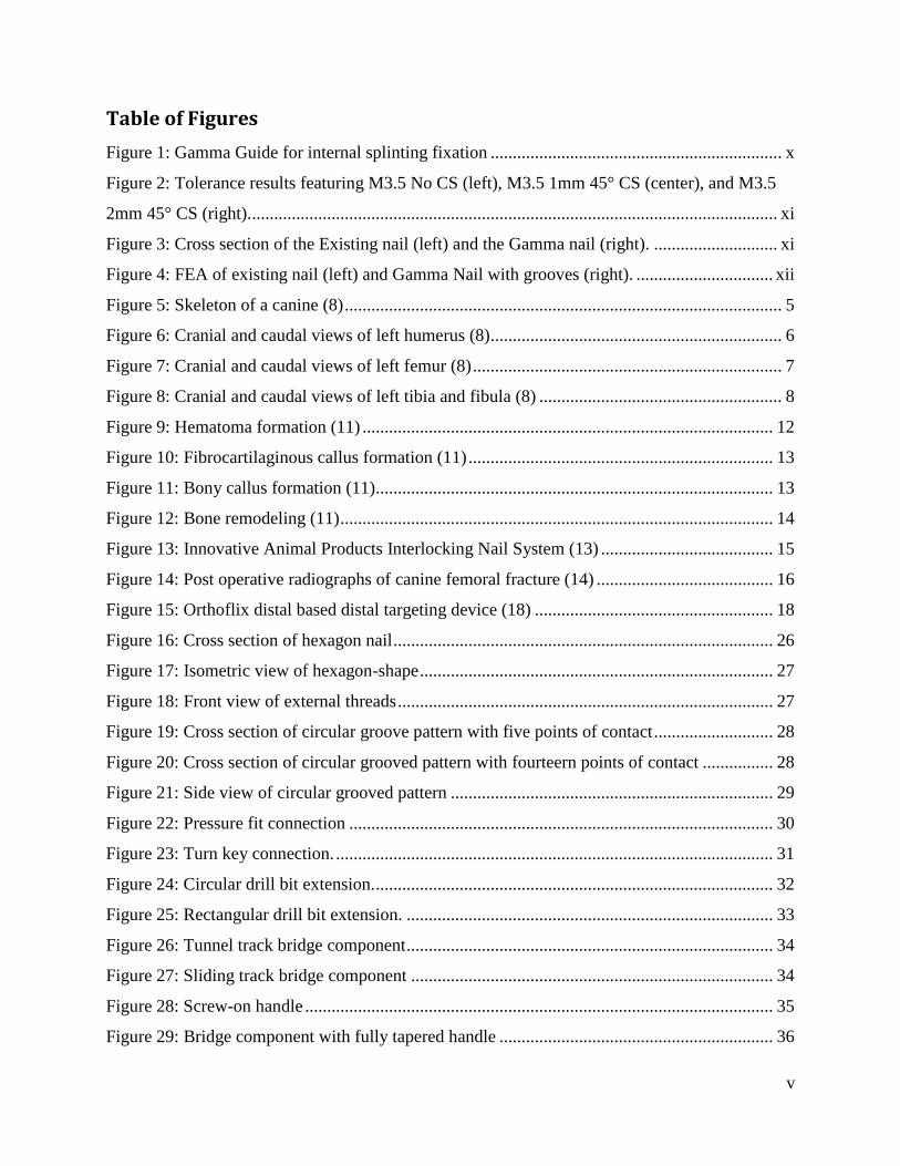
Figure 2: Tolerance results featuring M3.5 No CS (left), M3.5 1mm 45° CS (center), and M3.5
2mm 45° CS (right). ....................................................................................................................... xi
Figure 3: Cross section of the Existing nail (left) and the Gamma nail (right). ............................ xi
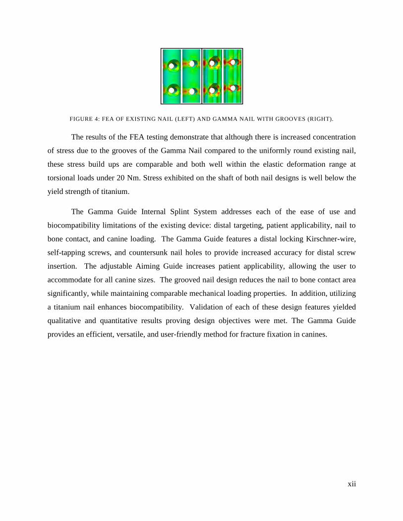
Figure 4: FEA of existing nail (left) and Gamma Nail with grooves (right). ............................... xii
Figure 5: Skeleton of a canine (8) ................................................................................................... 5
Figure 6: Cranial and caudal views of left humerus (8) .................................................................. 6
Figure 7: Cranial and caudal views of left femur (8) ...................................................................... 7
Figure 8: Cranial and caudal views of left tibia and fibula (8) ....................................................... 8
Figure 9: Hematoma formation (11) ............................................................................................. 12
Figure 10: Fibrocartilaginous callus formation (11) ..................................................................... 13
Figure 11: Bony callus formation (11).......................................................................................... 13
Figure 12: Bone remodeling (11) .................................................................................................. 14
Figure 13: Innovative Animal Products Interlocking Nail System (13) ....................................... 15
Figure 14: Post operative radiographs of canine femoral fracture (14) ........................................ 16
Figure 15: Orthoflix distal based distal targeting device (18) ...................................................... 18
Figure 16: Cross section of hexagon nail ...................................................................................... 26
Figure 17: Isometric view of hexagon-shape ................................................................................ 27
Figure 18: Front view of external threads ..................................................................................... 27
Figure 19: Cross section of circular groove pattern with five points of contact ........................... 28
Figure 20: Cross section of circular grooved pattern with fourteern points of contact ................ 28
Figure 21: Side view of circular grooved pattern ......................................................................... 29
Figure 22: Pressure fit connection ................................................................................................ 30
Figure 23: Turn key connection. ................................................................................................... 31
Figure 24: Circular drill bit extension. .......................................................................................... 32
Figure 25: Rectangular drill bit extension. ................................................................................... 33
Figure 26: Tunnel track bridge component ................................................................................... 34
Figure 27: Sliding track bridge component .................................................................................. 34
Figure 28: Screw-on handle .......................................................................................................... 35
Figure 29: Bridge component with fully tapered handle .............................................................. 36

vi
Figure 30: Pin connection ............................................................................................................. 36
Figure 31: Locking bolt for connection to aiming guide .............................................................. 37
Figure 32: Locking bolt for connection to bridge component ...................................................... 37
Figure 33: Double rod tunnel pin aiming guide ............................................................................ 39
Figure 34: Double rod aiming guide. ............................................................................................ 40
Figure 35: Oval solid body aiming guide ..................................................................................... 41
Figure 36: Side view of standard drill/bolt sleeve. ....................................................................... 41
Figure 37: Side view of standard screw ........................................................................................ 42
Figure 38: Side view of tapered screw .......................................................................................... 42
Figure 39: Distal support .............................................................................................................. 43
Figure 40: K-wire .......................................................................................................................... 44
Figure 41: Cross section of circular groove pattern ...................................................................... 45
Figure 42: Internal thread connection ........................................................................................... 46
Figure 43: Elliptical drill bit extension piece ................................................................................ 47
Figure 44: Bridge component with partially tapered handle ........................................................ 48
Figure 45: Squared solid body aiming guide ................................................................................ 49
Figure 46: Final design assembly ................................................................................................. 51
Figure 47: SolidWorks assembly of components ......................................................................... 52
Figure 48: Existing nail in CAD with highlighted area of importance ......................................... 54
Figure 49: Gamma nail in CAD with highlighted area of importance ......................................... 55
Figure 50: Top view of tolerance testing set up ............................................................................ 56
Figure 51: SIMULATION mesh as applied to Gamma nail ......................................................... 57
Figure 52: Torsional load application (pink) and nail tip fixture surfaces (green and blue) ........ 58
Figure 53: Data acquired from SolidWorks measurement tools ................................................... 59
Figure 54: Data acquired from SolidWorks measurement tool for Gamma system ..................... 60
Figure 55: Mass properties data collected using SolidWorks of the Existing nail ....................... 61
Figure 56: Mass properties data collected using SolidWorks of the Gamma nail ........................ 62
Figure 57: Tolerance test results graphed using MatLab .............................................................. 64
Figure 58: 25Nm Titanium Gamma nail and stainless steel Existing nail (left) ........................... 65
Figure 59: 25Nm Titanium Gamma nail and titanium Existing nail (right) ................................. 65
Figure 60: 25Nm Titanium Gamma nail stress concentration (left) ............................................. 66

vii
Figure 61: 25Nm Titanium Existing nail stress concentration (right) .......................................... 66
Figure 62: 25Nm Titanium Gamma (left) and Existing (right) nail designs ................................ 66

viii
Table of Tables
Table 1: Percent change value between the Existing nail and the Gamma nail ........................... 60
Table 2: Percent change highlighting the change in volume ........................................................ 62
Table 3: Tolerance testing data of noncountersunk hole .............................................................. 63
Table 4: Tolerance testing data of 1mm countersunk hole ........................................................... 63
Table 5: Tolerance testing data of 2mm countersunk hole ........................................................... 63

ix
Executive Summary
The United States has the greatest number of pets of any country world-wide, with 62%
of households owning at least one pet in 2010. Canines are the third most commonly owned pet
in the US, at just over 77 million nationwide. Furthermore, nearly 40% of US households
reported having at least one canine in 2010 contributing to veterinary market of 13.8 billion
dollars (1). One injury contributing to these veterinary expenditures is long bone fracture.
Substantial trauma results in this fracture type in the humerus, tibia, and particularly the femur,
which constitutes more than half of all long bone fractures in canines (2).
Current fracture treatment in canines includes bone plating and the Interlocking Nail
System. The Interlocking Nail System has been shown to provide enhanced mechanical stability
as well as provide a means for minimally invasive surgical implantation (3). However, the
current Interlocking Nail System is limited in terms of ease of use and biocompatibility. More
specifically, distal targeting, patient applicability, nail to bone contact, and canine loading reduce
the success of the procedure which can lead to failure of permanent fracture fixation in canines.
A redesigned system would aim to address these limitations, significantly reduce surgical
variability and procedure time, while considerably improving the overall quality of life for the
patient. The group aimed to accomplish these objectives while adhering to defined constraints of
time, the 2010-2011 academic year, and budget, $524.
Fixation of femur fractures via an intramedullary canal splinting device was the specific
aim of the group with the overall goal of creating a device applicable to other bones such as the
tibia and humerus at a variety of lengths to accommodate different size patients. To accomplish
internal splinting fixation, a grooved intramedullary nail is secured in the bone with four screws
using an external aiming guide: the Gamma Guide Internal Splint System for fracture fixation.
The full Gamma Guide developed by the group for a 185mm length, 8mm diameter nail
is shown in Figure 1. The Grooved Limited Contact Nail is secured in the bone via four self-
tapping screws in 2mm deep 45° M3.5 countersunk holes [Fig. 1, A]. For insertion into the
bone, the nail is attached to the Bridge Component [Fig. 1, B] via the Nail Extension Component
[Fig 1, C]. For screw insertion, the Aiming Guide [Fig. 1, D] is attached to the Bridge
Component along an internal track and locked into place via a Locking Bolt [Fig. 1, E]. The
Aiming Guide contains a variety of aiming holes for screw insertion of a variety of nail sizes.

x
Drill Sleeves [Fig. 1, F] can be placed through the Aiming Guide to assist drilling if the Aiming
Guide cannot be adjusted to the patient due to variable limb shape or curvature. A Kirschner-
wire [Fig. 1, G] can be placed through the Aiming Guide for bone location confirmation or
through a distal drill hole in the Aiming Guide to temporarily secure the device while more
proximal screws are inserted.
FIGURE 1: GAMMA GUIDE FOR INTERNAL SPLINTING FIXATION
Testing procedures were conducted to examine changes made in the design of the
Gamma Guide in terms of distal targeting and the limited contact nail. Tolerance testing was
performed to verify the performance of the newly designed countersunk holes of the Gamma
Nail. The three main components of the tolerance test set up include a tripod stand with a
micromanipulator, a fixed screw, and a testing nail. The three testing holes included no
countersink (M3.5 No CS), small countersink (M3.5 1mm 45° CS), and large countersink (M3.5
2mm 45° CS). The micromanipulator is used to adjust the screw mount for translational motion
in 1 mm increments ranging from 0-4 mm away from the center of the hole. After each
adjustment the group attempted to insert the screw into the hole. The above testing procedure
was performed four times by three subjects for each hole type. Using MatLab software, the
group graphed the tendency for the screw to enter each hole as a function of displacement from
the center. Green represents 100% success rate of screw insertion; red represents 0% success
rate of screw insertion as seen qualitatively in Figure 2. The large countersunk hole provided a
300% increase in tolerance compared to the non-countersunk holes and a 150% increase
compared to the small countersunk hole.

xi
FIGURE 2: TOLERANCE RESULTS FEATURING M3.5 NO CS (LEFT), M3.5 1MM 45° CS (CENTER), AND
M3.5 2MM 45° CS (RIGHT).
To verify the design of the limited contact feature of the Gamma Nail, nail to bone
contact area and volume calculations were conducted using the measurement tool in the
computer aided design (CAD) software, SolidWorks. The areas highlighted in blue below in
Figure 3 represent the contact points that were used for area calculations. The results of the
calculations indicated a 59% decrease in nail to bone contact area between the existing nail and
the Gamma Nail while only reducing the total volume by 10%.
FIGURE 3: CROSS SECTION OF THE EXISTING NAIL (LEFT) AND THE GAMMA NAIL (RIGHT).
Finite element analysis (FEA) was used to calculate approximate plastic deformation
torsional loads and provide qualitative insight into stress concentration variation between the
shape and material of the existing nail and the Gamma Nail. The SIMULATION application in
SolidWorks was used to run static torsional load simulations modeled after experimental Instron
testing. Stress concentrations were reported in Von Mises Stress (equivalent stress) and stress
concentration location was visually analyzed. Each nail design was subjected to torsional
loading at 5-50 Nm using increments of 5 Nm for both titanium and stainless steel nails. A 25
Nm torsional load was used to clearly demonstrate the stress concentration areas in both nail
designs. Plastic deformation occurs in the titanium nail at 25 Nm and in the stainless steel nail at
5 Nm. Plastic deformation first occurs at in the titanium Gamma Nail at 20 Nm and occurs in the
stainless steel Gamma Nail at 5 Nm.
xii
FIGURE 4: FEA OF EXISTING NAIL (LEFT) AND GAMMA NAIL WITH GROOVES (RIGHT).
The results of the FEA testing demonstrate that although there is increased concentration
of stress due to the grooves of the Gamma Nail compared to the uniformly round existing nail,
these stress build ups are comparable and both well within the elastic deformation range at
torsional loads under 20 Nm. Stress exhibited on the shaft of both nail designs is well below the
yield strength of titanium.
The Gamma Guide Internal Splint System addresses each of the ease of use and
biocompatibility limitations of the existing device: distal targeting, patient applicability, nail to
bone contact, and canine loading. The Gamma Guide features a distal locking Kirschner-wire,
self-tapping screws, and countersunk nail holes to provide increased accuracy for distal screw
insertion. The adjustable Aiming Guide increases patient applicability, allowing the user to
accommodate for all canine sizes. The grooved nail design reduces the nail to bone contact area
significantly, while maintaining comparable mechanical loading properties. In addition, utilizing
a titanium nail enhances biocompatibility. Validation of each of these design features yielded
qualitative and quantitative results proving design objectives were met. The Gamma Guide
provides an efficient, versatile, and user-friendly method for fracture fixation in canines.
1
1 Introduction
In a survey conducted in 2007 by the American Veterinary Medical Association, it was
found that more American families own pets than ever before (4). In 2010, 46.3 million United
States households owned canines which contributed to a 47.7 billion dollar pet industry. More
specifically, of the nearly 48 billion dollars spent on pets last year, 13.8 billion was spent on
veterinary expenditures as pet owners are expecting the same care for their animals that they
themselves would receive for similar aliments. Furthermore, pet expenditures are expected to rise
from 47.7 billion dollars in 2010 to 59.2 billion dollars in 2011, as this is one of the few markets
in the United States that was not affected by the recession (2).
With significant growth projected for pet and veterinary expenditures, there has been an
increased interest in improving veterinary devices, treatments, and overall care. One of the
companies devoted to these improvements is SECUROS, Inc. Harry Wotton, CEO and President
of SECRUOS, began this veterinary supply company upon graduation of Worcester Polytechnic
Institute and since has designed and sold orthopedic equipment constituting ten major products
line worldwide. According to Harry Wotton, “SECUROS has transformed the face of veterinary
orthopedics and we are known for very innovative, high quality products (5).” With the help of
SECUROS alongside competitors such as Innovative Animal Products, veterinary surgeons are
capable of treating injuries and avoiding the euthanization of pets.
A common injury in canines is long bone fracture including fracture of the humerus,
tibia, and femur. Common incidents such as falls and vehicular accidents can produce excessive
forces resulting in these fractures and necessary treatment. Unlike human fractures, dogs cannot
be commonly treated using external splinting devices because they are more active and cannot be
restricted as humans are post-fracture. Due to this, other correction techniques are used to
stabilize the fracture internally including bone plating and the interlocking nail. Bone plates
utilize a metallic plate which is secured to the external surface of the bone, over the fractured
region with screws. In contrast, the interlocking nail utilizes a metallic pin or rod which is
inserted manually into the medullary canal, using a hammer, and is secured internally with
screws. The interlocking nail is superior to bone plates due to its simplified procedure, reduced
cost, and reduced invasiveness; however the existing system for this procedure is limited in

2
terms of ease of use and biocompatibility. More specifically, distal targeting, patient
applicability, nail to bone contact and canine loading on the nail are all major shortcomings of
the existing design. The main goal of this project was to design an Internal Splint System for
fracture fixation in canines significantly improving the current limitations of the competitor‟s
product.

3
2 Background
Over the past two decades the popularity of pets has increased substantially in the United
States. American households owning at least one pet has risen from 56% to 62% in the twenty
year period from 1988 to 2008 according to the American Pet Products Association; in
particular, canines are the most popular American pet with 45.6 million U.S. households with
one or more canines. Increased pet popularity has resulted in veterinary expenditures becoming a
significant economic consideration for American pet owners. It is estimated that of the $47.7
billion projected to be spent in the U.S. pet industry, $13.8 billion will be spent on veterinary
care and supplies/medicine. A significant and growing market exists in the pet industry and in
particular the medical care of pets. Unlike in human healthcare which is an insurance based
system, pet healthcare is a largely voluntary “out of pocket” expense in which the pet owner has
both moral and economic motives that often conflict (1).
To understand all aspects of this project, the anatomy of canines, bone fracture, fracture
treatment, and future development have been thoroughly researched and described.
2.1 Anatomy of Canines
This section describes the microbial structure of bone, bone types, bone properties, and
bone classifications. It specifically highlights the humerus, femur, and tibia of canines as they are
of particular interest to the group.
2.2.1 Bone Structure
Bone is connective tissue that forms thin layers termed lamellae around longitudinal
tubes termed central canals. Each of these canals contains a blood vessel which supplies nutrients
to bone cells. Bone cells, also known as osteocytes, are located in the lamellae and are evenly
distributed throughout the bone tissue. These osteocytes coupled with extracellular matrix
composed of collagenous fibers comprise an osteon. Many of these repeating units comprise a
bone (6).

4
2.1.1.1 Bone Types
There are two types of bone, cortical or compact bone and cancellous or spongy bone.
Cortical bone comprises the diaphysis or the long shaft of the bone. It contains very tightly
packed tissue with continuous extracellular matrix. The diaphysis contains the medullary cavity,
which is a hollow hole located in the center that contains nerves and blood vessels. This cavity
also contains red and yellow bone marrow and is the site of red and white blood cell formation.
Cancellous bone comprises the epiphysis or the end of the bone. It contains many branching
bony plates which reduce the weight of the bone. The outer surface of the epiphysis is covered
with articular cartilage comprised of hyaline cartilage. Finally, the periosteum is a layer of
fibrous tissue that covers the entirety of the bone. Both the diaphysis and the epiphysis have very
high mechanical strengths, can be subjected to high compressive forces, and can resist bending
forces (6).
2.1.1.2 Bone Properties
The diaphysis and epiphyses both contribute to the mechanical properties of bone
including elastic modulus, yield strength, tensile strength, and density, among others. The elastic
modulus is 3-20 GPa. The yield strength is 77-114 MPa. The tensile strength is 42-109 MPa.
Finally, the density is 1.8-2.1 g/cm³ (7).
2.1.1.3 Bone Functions
Bones provide several functions to many species including support, protection, body
movement, blood cell formation, and the storage of inorganic salts. Support is essential in
carrying the loads that the body is subjected to. Bones of the limbs support body weight.
Protection is necessary for the organs inside the body. Bones of the skull protect the eyes, ears,
and brain and bones of the rib cage protect the heart and lungs. Bones are also vital for body
movement. Whenever movements such as abduction, adduction, flexion, or extension are
produced, bones and muscles interact to produce that movement. Bones are also essential for
blood cell formation known as hematopoiesis. Red blood cells are produced to carry oxygen to
all areas of the body to provide energy. White blood cells are produced to battle viral and
bacterial infections. Additionally, bones provide storage for inorganic salts such as calcium
which is used for vital metabolic processes in the body (6).

5
2.1.1.4 Bone Classifications
There are five types of bones in the canine skeleton including flat, irregular, sesamoid,
short, and long. Flat bones have broad surfaces such as the ribs and the scapulae. Irregular bones
have many different shapes and are typically connected to several additional bones such as the
vertebrae and many of the facial bones. Sesamoid bones are round and are embedded with
tendons such as the patella. Short bones are square such as the carpals and the tarsals. Long
bones have long longitudinal axes and expanded ends such as the humerus, femur, and tibia (8).
Figure 5 depicts the skeleton of a canine.
FIGURE 5: SKELETON OF A CANINE (8)
2.1.1.5 Humerus
The humerus is the bone in the upper arm of a canine that extends from the scapula to the
elbow. The proximal extremity of the humerus includes the head, the neck, the greater tubercle
and the lesser tubercle. The distal extremity includes the trochlea, capitulum, olecranon and
radial fossae. The head is the rounded section that articulates with the scapula. The neck is the
line along which the head and the tubercles fuse with the body of the humerus. The tubules are
processes extending from the surface of the bone. The greater tubule is located on the lateral side
and in most breeds, is higher than the head. The lesser tubule is smaller than the greater tubule
and is located on the medial side of the humerus. The trochlea articulates with the ulna and the
radius which is the most stable hinge joint inside of the body. The capitulum is another

6
articulation area, however, it only articulates with the radius. The olecranon fossa is a depression
on the caudal surface and receives the ulnar process during extension at the elbow. The radial
fossa is on the cranial surface and also aids with the motion of extension (8). Figure 6 depicts the
canine humerus.
FIGURE 6: CRANIAL AND CAUDAL VIEWS OF LEFT HUMERUS (8)
2.1.1.6 Femur
The femur is the thigh bone in the upper leg of a canine and is the heaviest bone in the
body. It is comprised of many parts including the head, fovea capitis, neck, trochanters, body,
trochlea, intercondylar fossa, supracondylar tuberosities, and epicondyles. The head of the femur
is enlarged and smooth. The fovea capitis femoris is the attachment area for the ligament of the
head of the femur. The neck of the femur is short and provides attachment for the joint capsule.
The greater and lesser trochanters provide attachment for the gluteal muscles and iliopsa
muscles, respectively. The body of the femur has a smooth cranial surface and a rough caudal
surface. The trochlea is the depression that articulates with the patella. The intercondylar fossa
provides an attachment area for the cruciate ligaments. The medial and lateral supracondylar
tuberosities provide attachment for the gastrocnemii. The medial and lateral epicondyles provide
attachment for the collateral ligaments (8). Figure 7 depicts the canine femur.

7
FIGURE 7: CRANIAL AND CAUDAL VIEWS OF LEFT FEMUR (8)
2.1.1.7 Tibia
The tibia is the shin bone in the lower leg of a canine and is wider than the distal head of
the femur. It is comprised of many parts including the condyles, intercondylar areas, tibial
tuberosity, body, and medial malleolus. The medial and lateral condyles articulate with the
condyles of the femur. In addition, the lateral condyle also articulates with the head of the fibula.
The cranial intercondylar area provides attachment for the cranial parts of the menisci and the
cruciate ligaments. The caudal intercondylar area provides attachment for the caudal part of the
medial meniscus. The tibial tuberosity provides attachment for the quadriceps femoris, biceps
femoris, and sartorius. The body of the tibia has a unique shape comprised of a triangular top, a
cylindrical middle, and a square bottom. The medial malleolus articulates with the fibula (8).
Figure 8 depicts the canine tibia.

8
FIGURE 8: CRANIAL AND CAUDAL VIEWS OF LEFT TIBIA AND FIBULA (8)
2.2 Bone Fracture
This section describes the classifications of bone fracture and fracture healing. It
specifically highlights fractures in the humerus, femur, and tibia of canines as they are of
particular interest to the group.
2.2.1 Bone Fracture Classifications
Despite their immense strength, bones are susceptible to breaks or discontinuities,
medically referred to as fractures. Bone fractures can be a result of two conditions; physiological
or environmental. Physiological conditions refer to pathological factors, such as osteoporosis and
bone cancers, among others. For this reason, they are classified as pathological fractures.
Environmental conditions refer to external factors, such as high impact forces or torsion. These
types of fractures are categorized based on one or more of the following classifications (9):
1. Position
2. Completeness
3. Orientation
4. Penetration

9
2.2.1.1 Position
The first classification of externally caused fractures is based on position. Specifically,
this classification refers to the position of the bone ends after a fracture. Fractures identified
under the position classification fall into two categories: displaced or non-displaced. Displaced
fractures describe a bone fracture in which the bone ends do not retain their normal position and
are instead out of normal alignment. Non-displaced fractures describe a bone fracture in which
the bone ends retain their normal position (9).
2.2.1.2 Completeness
The second classification of external fractures is based on completeness. Completeness
refers to the extent, or completeness, of the bone fracture. Fractures identified under the
completeness classification fall into two categories: complete or incomplete. Complete fractures
describe a bone fracture in which the bone is entirely broken through. Incomplete fractures
describe a fracture in which the bone is only partially broken through (9).
2.2.1.3 Orientation
The third classification of external fracture is based on orientation. Orientation refers to
the direction of the fracture relative to the long axis of the bone. Fractures identified under the
orientation classification fall into two categories: linear or transverse. Linear fractures describe a
fracture in which the bone breaks parallel to the long axis. Transverse fractures describe a
fracture in which the bone breaks perpendicular, at a right angle, to the long axis (9).
2.2.1.4 Penetration
The fourth classification of external fracture is based on penetration. Penetration refers to
whether or not the fracture penetrates through the skin. Fractures identified under the skin
penetration classification fall into two categories: open (compound) or closed (simple). Open
fractures refer to a fracture in which the bone penetrates the skin. Closed fractures refer to a
fracture in which the bone does not penetrate the skin (9).
10
2.2.1.5 Additional Fracture Classifications
Bone fractures can be further classified into a variety of other categories that include
location of fracture, external appearance of fracture, or nature of the break. Common types of
fractures include (9):
1. Comminuted
2. Spiral
3. Depressed
4. Compressed
5. Condylar
6. Greenstick
Comminuted fractures occur when a bone breaks into three or more pieces. These are commonly
seen in older patients whose bone becomes brittle over time. Spiral fractures occur when
excessive twisting, or torsional force, is applied to the bone, resulting in a jagged spiral break (6).
Depressed fractures occur when a bone portion is pressed inward, commonly found in the skull.
Compression fractures occur when bone is crushed or smashed; commonly occurs in porous
bones, often bones that are osteoporotic. Condylar fractures describe a break in the epiphysis of
the bone. One common type of condylar fracture is one in which the epiphysis separates from the
diaphysis along the epiphyseal plate; this occurs when cartilage cells begin to die and
calcification occurs (9). Greenstick fractures describe the phenomena in which bone breaks
incompletely. This is unlike an incomplete fracture in that one side of the bone breaks while the
other side bends. Greenstick fractures are commonly seen in young patients, whose bones have
more matrixes and are more flexible (6).
2.2.1.6 Humeral Fractures
Humeral fractures make up 10% of all fractures in canines and 34% of all forelimb
fractures in canines. Although Yorkshire Terriers and Miniature Schnauzers have been shown to
be at an increased risk, the size of canines did not seem to affect their susceptibility to humeral
fracture. Most humeral fractures in canines are condylar fractures. Surgeons face some difficulty
in terms of surgical repair regarding humeral fractures due to the bones close proximity to
several neurovascular bundles and the presence of large muscle masses. On a case by case basis,
veterinary surgeons have opted to use a variety of surgical repair methods for treatment of
humeral fractures. Methods of treatment have included Kirschner wire, bone screws,

11
intramedullary pins and cerclage wires, external fixators, plate fixation and interlocking nails
(10).
2.2.1.7 Femoral Fractures
Femoral fractures present a challenge to veterinary surgeons. Due to the anatomical
positioning and location of the bone, there are limitations in applying an external fixator because
it must pass through large muscle masses. This problem accelerates as the size of the patient
increases. Due to these limitations in applying external skeletal fixators to the femur, the
treatments of choice for a femoral fracture include intramedullary pins and bone plates (3).
2.2.1.8 Tibial Fractures
Tibial fractures affect small canines differently than large canines. In small canines, it is
impossible to stabilize the bone without opening the fracture site with a device as simple as an
external fixator. An external fixator would be the ideal method of treatment because it preserves
the vascular envelop by not opening the fracture site. Minimally invasive procedures are
preferred to preserve the vascular envelope as well. In large canines, the disruption of blood
supply may be required in order to rigidly fix the fracture. This may be an acceptable tradeoff to
obtain long term stability. The treatments of choice for tibial fractures are external fixators and
intramedullary pins and cerclage wires. Intramedullary pins and cerclage wires require an
invasive procedure but are often used in cases of severe fractures. These fractures require greater
stabilization than the external fixation can provide (3).
2.2.2 Fracture Healing
After a fracture, the bone ends must be realigned to ensure proper healing. The
realignment of broken bone ends is called reduction. There are two categories of reduction:
closed (external) reduction or open (internal) reduction. Closed reduction describes the processes
of shifting the bones back into normal alignment by a veterinarian. Open reduction describes the
processes of realigning the bone and securing the ends surgically, whether it is with rods, plates,
pin, or wires, among others (9).

12
Once the bone is reduced, regardless of which method of reduction, it is often
immobilized to allow the natural healing process to begin. The repair of simple fractures occurs
in six to eight weeks and involves four major stages (9):
1. Hematoma formation
2. Fibrocartilaginous callus formation
3. Bony callus formation
4. Bone remodeling
2.2.2.1 Hematoma Formation
Regardless of classification of bone fracture, when a fracture occurs, blood vessels found
within the bone canal, called the medullary cavity, rupture. The ruptured vessels allow for blood
to escape the circulatory system and invade the fracture site, medically referred to as
hemorrhaging, or bleeding. Soon after, the blood begins to coagulate, forming a blood clot, or
hematoma, between the broken bone ends at the fracture site (6). This ceases additional
hemorrhaging from the ruptured blood vessels found within the bone and the surrounding tissues.
The blockage caused by the hematoma deprives mature bone cells, or osteocytes, of the oxygen
and nutrients found within blood, so the vessels surrounding the fracture dilate, causing swelling
and inflammation of the tissue (9). Figure 9 depicts hematoma formation.
FIGURE 9: HEMATOMA FORMATION (11)
2.2.2.2 Fibrocartilaginous Callus Formation
After several days, granulation or soft callus tissue forms at the wound site. Capillaries
grow into the hematoma and restore blood flow to the osteocytes. Phagocytes, a white blood cell
know for ingestion of foreign particles and dead cells, invade the wound site and begin removing
debris and perform general wound site maintenance (6). Fibroblasts and osteoblasts then enter
the fracture site to begin bone reconstruction. Fibroblasts produce collagen fibers that connect

13
the broken bone ends and help produce cartilage matrix. Osteoblasts begin to form spongy bone,
which bulges from the fracture site and slowly calcifies. This bulging structure is called the
fibrocartilaginous callus, and acts as a splint (9). Figure 10 depicts fibrocartilaginous callus
formation.
FIGURE 10: FIBROCARTILAGINOUS CALLUS FORMATION (11)
2.2.2.3 Bony Callus Formation
Within a week, bony callus formation begins. The fibrocartilaginous callus gradually
calcifies becoming a denser, harder bony callus. This continues for several weeks until a firm
union is formed between the fracture sites (9). Figure 11 depicts bony callus formation.
FIGURE 11: BONY CALLUS FORMATION (11)
2.2.2.4 Bone Remodeling
Lastly, bone remodeling occurs. During this final phase of natural bone fracture healing,
the bony callus is remodeled over several months. The excess bone found bulging outside the
fracture site, caused by the fibrocartilaginous callus formation, is gradually removed. Compact
bone is then laid down to reconstruct the shaft walls of the bone (9). Figure 12 depicts bone
remodeling.

14
FIGURE 12: BONE REMODELING (11)
After an average of six weeks to three months, most simple fractures are completely
healed. More complicated fractures, such as compound fractures, can take additional time to
undergo the natural bone healing process (6). The final bone structure closely resembles that of
the original unbroken bone, largely due to the fact that the bone responds to the same mechanical
stressors during the healing process (9).
2.3 Fracture Treatment via Current Methods
This section describes fracture treatments such as plate fixation and the interlocking nail
system for canine bone fractures. The interlocking nail system is of particular interest to the
group.
2.3.1 Development
The Interlocking Nail System (IN System) has been a successful treatment to heal
fractures of the humerus, femur, and tibia. In 1989, R. Tass Duelan, DVM, began to investigate
the possibility of using the IN System for veterinary orthopedics. Results from mechanical and
clinical trials demonstrated a need for this system in the veterinary market. The veterinary IN
System was developed specifically for the veterinary surgeon to provide a practical surgical
procedure requiring minimal supplementary equipment. Some advantages of the veterinary IN
System are that no power reaming is required to insert the nail, surgeons can achieve precise
screw hole targeting without fluoroscopy, and the device is compatible with AO cortical screws
or IN Solid Cross Locking Bolts. There have been three generations of veterinary IN Systems,
none of which have significantly changed the original device (12). The most recent IN System is
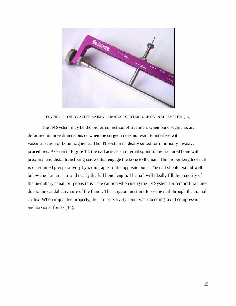
the third generation product as seen below in Figure 13.
15
FIGURE 13: INNOVATIVE ANIMAL PRODUCTS INTERLOCKING NAIL SYSTEM (13)
The IN System may be the preferred method of treatment when bone segments are
deformed in three dimensions or when the surgeon does not want to interfere with
vascularization of bone fragments. The IN System is ideally suited for minimally invasive
procedures. As seen in Figure 14, the nail acts as an internal splint to the fractured bone with
proximal and distal transfixing screws that engage the bone to the nail. The proper length of nail
is determined preoperatively by radiographs of the opposite bone. The nail should extend well
below the fracture site and nearly the full bone length. The nail will ideally fill the majority of
the medullary canal. Surgeons must take caution when using the IN System for femoral fractures
due to the caudal curvature of the femur. The surgeon must not force the nail through the cranial
cortex. When implanted properly, the nail effectively counteracts bending, axial compression,
and torsional forces (14).

16
FIGURE 14: POST OPERATIVE RADIOGRAPHS OF CANINE FEMORAL FRACTURE (14)
2.3.2 Components
The interlocking nail features seven major components: the nail, nail extension, insertion
tool, external jig, guide sleeve, tap guide, and screw. The nail acts as an internal split for fracture
fixation and contains predrilled proximal and distal holes transverse to the long axis of the nail.
The nail extension allows for tapping of the nail into the medullary cavity as well as a means for
jig attachment. The insertion tool aids in nail insertion into the medullary cavity. The external jig
allows for assistance in locating and inserting screws through the near cortex, IN holes, and far
cortex. The guide sleeve allows for precise predrilling of the screw holes and the tap guide
allows for precise insertion and attachment of the screw. The screw locks the nail in place
through both cortexes of the bone (12).
2.3.3 Procedure
Preoperative procedure for IN system requires the use of a template to determine the
proper length of the nail for the fracture. The medullary cavity is then prepared using a manually
driven reamer. The nail is then attached to the appropriate extension (femoral or tibial) using a
hex driver to tighten the internal screw mechanism inside the IN extension. The insertion tool is
then attached to the IN with a power drill. The nail is then inserted to the medullary cavity and
the proximal end of the nail is inserted a depth of 2 mm below the joint surface. An external drill
jig is the attached to the IN system for screw insertion. A guide sleeve is inserted into the
active/open holes in the drill jig and the drill is inserted through the near cortex, IN hole, and far
17
cortex. The drill guide and drill are replaced with a tap guide and screw, respectively. The screw
is inserted manually via a screwdriver. This process is repeated until the nail is secure proximally
and distally and the entire IN system is then removed.
2.3.4 Limitations
There are several limitations of the current Interlocking Nail System identified by the
group including material properties, nail contact inside the medullary cavity, and distal screw
placement. These three limitations were thoroughly researched in the literature.
2.3.4.1 Material Properties
Material properties of the veterinary IN system are a limiting factor in existing devices.
Stainless steel is the most popular metal used for veterinary IN fixation whereas titanium is the
most popular metal used for human IN fixation. Previous studies have revealed that stainless
steel INs, while less expensive, are inferior to titanium INs regarding both mechanical and
biocompatibility properties (15). Specifically, Uhthoff et al showed that titanium is advantageous
to stainless steel for fracture fixation in canines due to its lower elastic modulus and increased
biocompatibility, osteointegration, and magnetic resonance imaging (MRI) compatibility (16).
2.3.4.2 Nail to Bone Contact
A limitation of the current IN system involves the use of a nail which can cause
additional damage to blood supply after the initial disruption due to fracture. Bone necrosis, or
the premature death of cells and tissues, can occur after the implantation of nails due to lack of
blood supply, also known as ischemia. Necrosis differs from apoptosis, which is naturally
occurring cell death, because of differing immune responses. In necrosis, phagocytes are not
triggered by the immune system to ingest the deceased bone tissue, which can lead to delayed
healing, infection, re-fracture, and secondary surgery to remove the necrotic tissue (17).
2.3.4.3 Distal Screw Targeting
The existing IN system features a proximal based distal targeting device (DTD) that is
used to locate and insert distal screws in canines. These DTD systems have proven ineffective
for distal interlocking screw (DIS) placement because they do not accurately compensate for
unavoidable nail deformation during insertion. This limitation has forced veterinarians to use
free-hand techniques to properly locate and insert distal screws in canines. This technique is

18
dependent upon the surgical skill of the veterinarian, and therefore is highly variable and
inconsistent. For these reasons, DIS placement technique accounts for a significant amount of
time and frustration during surgery. Additionally, proper placement of DISs are critical to the
mechanical stability of the IN system (18).
To enhance repeatability and ease of use of distal targeting in humans, Orthoflix has
developed a distal based DTD for INs seen in Figure 15. The Orthoflix DTD attaches to the
proximal end via an external guide bar (B) that runs the entire length of the nail. A T-handled rod
(A) is externally clamped (C) to the guide rod. A hole is then drilled through the anterior cortex
of the bone until the anterior IN surface is reached. The T-handled rod is inserted though this
hole and accommodates for any flexion in the IN. The DISs are inserted through the guide holes
in the clamp and the T-handled rod is then removed. The Orthoflix system used in combination
with fluoroscopy in human care is too expensive for veterinary care and therefore has not been
incorporated in veterinary systems (18).
FIGURE 15: ORTHOFLIX DISTAL BASED DISTAL TARGETING DEVICE (18)
19
2.4 Clinical Significance
The millions of American households owning canines are affected by the billions spent
each year on veterinary care and the moral costs that coincide with these economic decisions. A
common canine injury contributing to care expenses is due to substantial trauma resulting in long
bone fracture of the tibia, humerus, and particularly the femur which constitutes over half of all
long bone fractures in canines (19). Bone is naturally very strong in compression but supra-
physiological forces such as axial tension, excessive bending, or torsion forces can cause bone
failure. Common incidents such as falls and vehicular accidents can produce these excessive
forces resulting in fracture. A canine patient suffering from long bone fracture differs from a
human patient with the same ailment; the nature and unpredictable activity levels of canines
require that internal fixation methods be used in bone repair. If done properly, internal fixation of
a canine fractured long bone speeds the healing process providing the animal with a more
comfortable and practical recovery (20).
One prominent technique for treating long bone fracture in canines is the IN system. The
IN system is composed of a nail centrally inserted in the medullary cavity of the bone fixed in
place by screws or bolts applied transversely through the bone cortexes and nail. Existing IN
systems are limited in several applications including material, nail contact, and distal screw
insertion. Current IN systems feature stainless steel components, which have been shown
through previous research to be inferior to alternative metals for implantation in the body.
Additionally, these systems contain nails that can inhibit blood supply to the native bone tissue
and fracture site through unnecessary nail–to–bone medullary contact. Lastly, these systems
consist of a proximal based DTD, which do not accurately compensate for nail deformation
during insertion, making it difficult for proper distal screw fixation. If these limitations could be
properly addressed, the IN system would be drastically improved.
In canine fracture fixation, there is a need for a redesigned IN system that features a nail
with favorable material properties and reduced blood flow obstruction and bone necrosis and
allows for accurate distal screw insertion. IN systems have been shown to provide enhanced
mechanical stability as well as provide a means for minimally invasive surgical implantation.
Such a redesigned IN system would significantly reduce surgical variability and procedure time
while considerably improving the overall quality of life for the patient.
20
3 Project Approach
In order for the group to better understand the project after the initial client statement was
given, the group identified the project objectives, constraints, functions and means, before
revising the client statement.
3.1 Initial Client Statement
The initial client statement was provided by project advisor Glenn R. Gaudette. The
initial client statement read as follows:
Design an internal splint system for use in canine with broken femurs. The system should
include all hardware necessary to complete the implantation.
3.2 Objectives
It was critical for the group to conduct clinical research and interviews with users and
clients in order to understand the objectives of the design. The potential users of the refined
interlocking nail system are veterinary surgeons. The group interviewed three board certified
surgeons to determine the problems they encounter while using the current device and any
components of the current device that need improvement. The client is Harry Wotton, President
and CEO of SECUROS. Harry Wotton has found a clinical need for the device and is using the
MQP group as the design team for his company to produce a refined interlocking nail system. A
pairwise comparison chart was used to evaluate objectives based on importance relative to the
design after the group conducted interviews and research, which can be viewed in Appendix A:
Pairwise Comparison Chart.
The main goal of the device is to provide permanent fixation of fractured bones in
canines including the humerus, femur, and tibia. The following objectives were determined to
address different aspects of the design critical for meeting user and client needs. The device must
be functional allowing for fracture fixation by means of an internal splint. A device that is not
functional is not clinically practical and will deter acceptance by users. The device must also be
user friendly based on surgeons‟ preference in alternative fracture fixation methods due to the
difficulty experienced when using the current interlocking nail system. While maintaining ease
of use, the device must also be safe for both the user and the patient. The device must allow for
the procedure to be consistent and repeatable. It must be a simple procedure in order to be

21
performed easily by any practicing veterinarian. Veterinarians have explained that more
experienced surgeons will tolerate the current interlocking nail system because they have drafted
ways to manipulate the device to work properly through years of experience. Veterinarians new
to the field are less likely to use the current method and choose alternative fracture fixation
methods that are simple. The procedure must be minimally invasive in that it must be no more
invasive than the current technology. The group‟s client defined minimally invasive as
increasing the speed and ease of procedure resulting decreased trauma to the patient. The
material for both the nail and the screws should be titanium. Clinical research demonstrated the
potential harm when using different materials such as a titanium nail and stainless steel screws in
vivo in canines. Veterinarians have demonstrated the need for a device that allows distal holes to
be located easily therefore the device must be structurally sound. The device must also be
durable in that it can withstand the mechanical loads presented by the body as the device is a
permanent implant. The device must be easy to maintain and easy to manufacture. Finally, the
device must be similar in price range to the existing technologies although an increase in price
within twenty percent is acceptable if the product offered is advantageous. The group has used
this list of objectives to determine the most important areas to address within the design criteria
to end with a final product that will satisfy both the client and the user.
3.3 Constraints
The team has identified a series of constraints that while limiting design possibilities,
work to narrow the scope of the project and help to define the project goals. Initially, a design
budget of approximately $600 was established for the eight month project. This budget limits
prototyping and testing capabilities of the team for studies done at the Worcester Polytechnic
Institute. An official company budget supplied by SECUROS has not been established; expenses
incurred via the manufacturing of scale and actual material prototypes to be tested are to be paid
and decisions made at the discretion of SECUROS. Prototype and sample supply has been
discussed with SECUROS with the understanding that model guide systems can be manufactured
at the completion of the design process with the potential of actual material nail manufacturing
for mechanical testing upon the approval of nail design. SECUROS supplied resources, while
beneficial for future device validation, are understood to be limited to a few samples at the
approval and willingness of the company.

22
In addition to institutional monetary restrictions and company supplies, the design of the
new interlocking nail fixation system is constrained by its purpose. The concept of an
interlocking nail fixation system is based on the idea of internal fixation: the nail is to be
implanted within the bone canal and fixed via screws or bolts to the bone. By nature of this
fixation method, the design must be composed of highly biocompatible materials. Since the nail-
bolt/screw construct is purposed to provide mechanical support to the injured bone, it does not
need to resolve, rather the material must maintain its mechanical integrity. In addition, the
procedure for insertion of the nail is relatively invasive as the implant will be inserted deep to the
bone it is designed to support; because the nail-bolt/screw complex is within the medullary
cavity degradation, wear and infection in or on the nail cannot occur. Before the nail is even
inserted it, the bolts, and the guide must be sterilizable via an inexpensive method. Although not
explicitly limited to autoclave sterilization, the veterinary market is most receptive to reusable-
easily sterilizable materials which include metals such as stainless steel and titanium which can
easily be autoclaved.
The final design and preliminary testing into the viability of the mechanisms and
techniques involved in the design must be completed by the middle of April, 2011. While
completion of the design is on a strict time schedule with definite deadlines, the manufacturing
schedule of the final design limits the design possibilities further. Parts of the system including
the nail, bolts/screws, and aiming guide must be easily manufactured either at Worcester
Polytechnic Institute or the facilities supplied by SECUROS at relatively low cost and time. The
demand in the veterinary market is not only for a mechanically/physiologically superior
interlocking nail design but also an economically equivalent product as current competition
within 20% of the cost as determined by SECUROS. Part of this cost will result from the design
materials; more control over the cost can be found in the ease of manufacturability. As
mentioned, manufacturing is limited to the facilities at Worcester Polytechnic Institute as well as
those at and contracted by SECUROS. The facilities at SECUROS can only be used between
normal manufacturing cycles of other products limiting time of manufacture which will limit the
complexity of the final design. The design of a novel interlocking nail fixation system is
constrained by a variety of parameters including design project budgets, design material, device
sterilization, project duration, and part manufacturability which in addition to limiting design

23
options, also help to narrow the scope of the project and provide the design with well-defined
parameters.
3.4 Functions and Means
To achieve the project objectives, functions and means were identified through a
function-means tree. This chart aids in the identification of the primary functions of the design
and the means to accomplish them and can be seen in Appendix B: Function-Means Tree. When
examining the overall IN system, the functions necessary for a successful device and procedure
include internally fixating the bone fracture, guiding the insertion of the device, reducing bone
atrophy, minimizing risk of infection, and reducing overall device complexity.
Internally fixating the bone fracture is the most important function as proper internal
fixation leads to timely bone fracture healing and full recovery: existing IN systems utilize a
central nail design that is fixed in the medullary cavity via screws or bolts through the bone
cortexes. Guiding the insertion of the device is a crucial component to a successful procedure as
it provides veterinarians with the ability to achieve consistent and repeatable internal fixation: an
external guide is necessary to achieve proper screw placement and alignment through the bone
cortex and central nail. Reducing bone atrophy is a significant function, as the device must meet
the mechanical requirements while minimizing adverse effects on the native bone: reduced stress
shielding can prevent bone atrophy and would greatly benefit the design. It also is important for
the device to minimize the risk of infection through precise manufacturing, sterilization, and
material consistency. Lastly, reducing overall device complexity would aid in the achievement of
objectives: external guide adjustability, reduced number of parts, elimination of additional
surgical technique, and ergonomic components are means to achieve this function. Each of these
functions and means must be considered throughout the entire design phase.

24
3.5 Revised Client Statement
After successfully going through each step of the design process, the group revised the
initial client statement to provide a better scope for the goal of the project. The revised client
statement read as follows:
Design an internal splint system for fracture fixation in medium-sized (60 lbs) adult
canines humeral, femoral, or tibial fractures. The interlocking nail system must maintain
permanent fracture fixation. The system must feature a nail that acts as an internal splint
for the bone fracture and provides favorable material properties that promote
mechanical stability and biocompatibility. The nail must also feature limited contact
within the medullary cavity of the bone to reduce blood flow obstruction to native tissue
and the bone fracture site. The system must also feature an external aiming guide for
accurate screw insertion, particularly, distal screw insertion. The interlocking nail
system must be easy to manufacture and sterilize while maintaining durability. The
system must include all hardware necessary to complete the implantation and be of
comparable cost to existing technologies. The design and development of the internal
splint system must be completed by April 2011.

25
4 Design
This section includes the limitations of the current device, preliminary designs, as well as
the final design of the Gamma Guide.
4.1 Limitations of Current Device
Through background research, three limitations of the current IN system were identified
including the material, nail contact within the medullary cavity, and distal screw insertion. These
limitations are explained in depth in Section 2.3.4 Limitations Briefly, stainless steel INs are
inferior to titanium INs in regards to their mechanical and biocompatible properties (15).
Additionally, bone atrophy can occur after the IN is implanted due to lack of blood supply to the
native tissue (17). Finally, existing IN systems have ineffective distal interlocking screw
placement as they do not accommodate nail deformation (18). Through interviews with board
certified veterinary orthopedic surgeons, Dr. Richard Rodger, Dr. Matthew Barnhart, and Dr.
Randy Basinger, the limitations identified through literature were reiterated. Dr. Rodger
emphasized the significance of using the same metal for all components of the IN system to
avoid tumor formation in canines. Dr. Barnhart recommended the implementation of a method to
locate the distal bone to ensure proper distal screw insertion as well as eliminating the need for
an array of aiming guides to accommodate varying canine size. Dr. Basinger highlighted the
tendency for current IN systems to form a cold-weld, making it difficult to disconnect the nail
from the external aiming guide. Detailed interviews with the veterinary orthopedic surgeons can
be found in Appendix C, D, and E, respectively. Each of these disadvantages and limitations
were considered throughout the conceptual and preliminary design phases.
4.2 Preliminary Nail Designs
Current interlocking nails for fracture fixation include a variety of sizes (lengths and
diameters) to service a variety of bones and animal sizes. While the design of any system should
include a variety of nail sizes, the shape and connection/detachment of the nail are distinguishing
features of each system. The shape of the nail must allow for easy insertion without unnecessary
damage to the bone and optimal recovery of the tissue post-surgery. Limited contact on the bone-
nail interface should be considered so as to allow for medullary blood vessel regeneration during
healing but not reduce the mechanical integrity of the system. In addition, since nail insertion is a
skill subject to the performance and experience of the surgeon and alignment of screw holes with

26
the guide is essential to the success of implantation, attachment of the nail to the guide device
should be strong enough to allow for manipulation (turning) as well have exact alignment with
the exterior aiming holes of the guide.
4.2.1 Limited Contact
The design of a limited contact nail is an objective established in the initial client
statement. The purpose of limiting contact of the nail with the internal medullary cavity walls is
to reduce osteolysis due to wear and lack of revasculature upon healing. The project group
designed four limited contact nails including the Hexagon, the External Threaded, and two
Circular Groove Patterned nails.
4.2.1.1 Hexagon
A Hexagon-Shaped cross section would reduce the amount of Titanium that comes into
contact with the internal medullary cavity wall. The nail would have six points that would come
into contact with the medullary contact after nail insertion as seen below in Figure 16.
FIGURE 16: CROSS SECTION OF HEXAGON NAIL
The isometric view of this nail below in Figure 17 exemplifies the full length of the nail with the
six abrupt angle changes. These six points are expected to have high stress concentrations.
Transition of cross sections causes high stress. The abrupt transitions that occur along the
hexagon cause higher stresses. The stress “flow lines” then become crowded which cause higher
stress concentrations (21).

27
FIGURE 17: ISOMETRIC VIEW OF HEXAGON-SHAPE
4.2.1.2 External Thread
A nail manufactured with an external thread would reduce nail to bone contact as well as
act as a locking mechanism for the nail inside of the medullary canal. The current method for
inserting the nail is to hammer the nail into the medullary canal. This design uses a well know
and easily manufactured connection method that will be reliable both for insertion and extraction
of the nail. Having external threads on the nail, as seen below in Figure 18, will reduce the
contact of the nail to the medullary canal by one half.
FIGURE 18: FRONT VIEW OF EXTERNAL THREADS

28
4.2.1.3 Circular Groove Pattern
Current veterinary bone plates for fracture fixation have limited contact features. The
concept of having material removed between holes to reduce nail to bone contact inspired the
Circular Groove Pattern design. The same concept that has been used in current orthopedic bone
plate design will be used for a circular cross section rather than the rectangular nature of the
limited contact bone plate. The concept can be seen below in Figure 19 with a low number of
contact points.
FIGURE 19: CROSS SECTION OF CIRCULAR GROOVE PATTERN WITH FIVE POINTS OF CONTACT
The amount of grooves cut out of the original circular nail could be increased at lesser values to
increase the nail to bone contact as seen below in Figure 20.
FIGURE 20: CROSS SECTION OF CIRCULAR GROOVED PATTERN WITH FOURTEERN POINTS OF
CONTACT
One concern with this design is the stress concentrations along the edges where the
grooves are cut out. The transition across cross sections results in high stresses. However, with a
smoother change seen in this design compared to abrupt change allows the “flow lines” to be less
crowded, resulting in a lower stress concentration (21). The side view of the nail with the
Circular Grooved Pattern can be seen below in Figure 21.
29
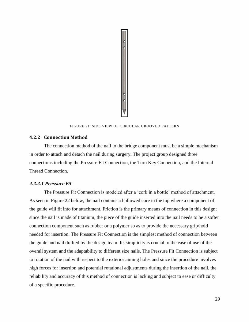
FIGURE 21: SIDE VIEW OF CIRCULAR GROOVED PATTERN
4.2.2 Connection Method
The connection method of the nail to the bridge component must be a simple mechanism
in order to attach and detach the nail during surgery. The project group designed three
connections including the Pressure Fit Connection, the Turn Key Connection, and the Internal
Thread Connection.
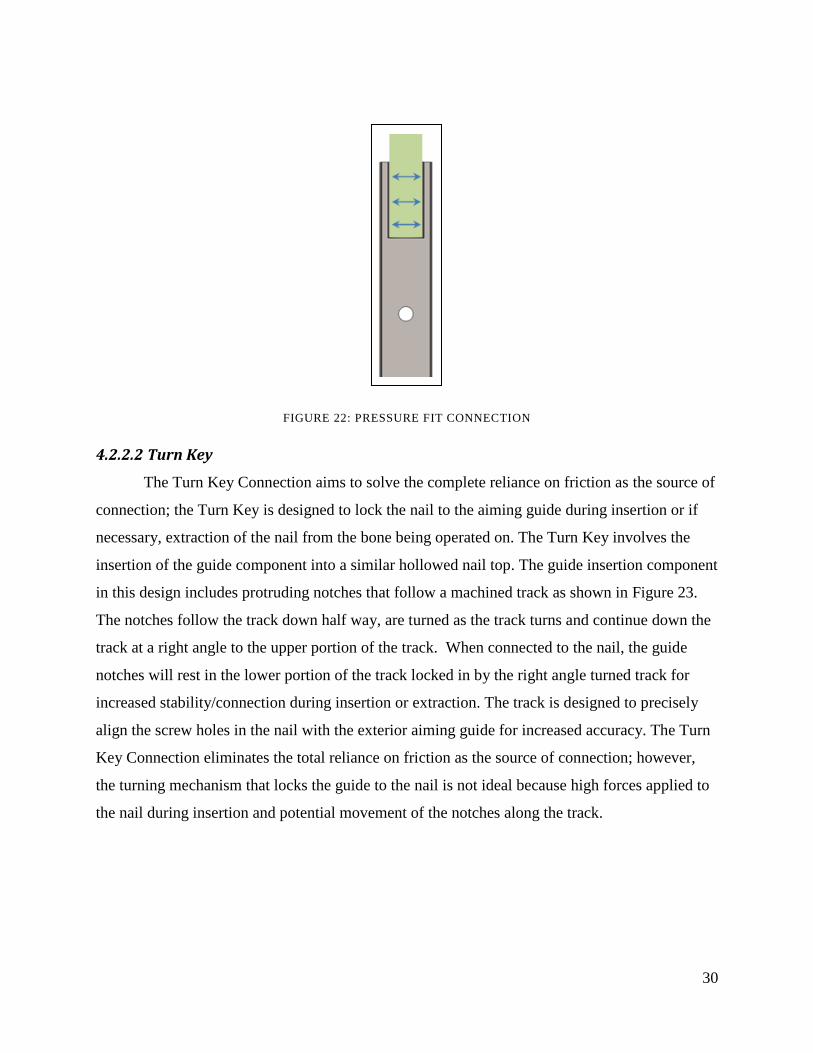
4.2.2.1 Pressure Fit
The Pressure Fit Connection is modeled after a „cork in a bottle‟ method of attachment.
As seen in Figure 22 below, the nail contains a hollowed core in the top where a component of
the guide will fit into for attachment. Friction is the primary means of connection in this design;
since the nail is made of titanium, the piece of the guide inserted into the nail needs to be a softer
connection component such as rubber or a polymer so as to provide the necessary grip/hold
needed for insertion. The Pressure Fit Connection is the simplest method of connection between
the guide and nail drafted by the design team. Its simplicity is crucial to the ease of use of the
overall system and the adaptability to different size nails. The Pressure Fit Connection is subject
to rotation of the nail with respect to the exterior aiming holes and since the procedure involves
high forces for insertion and potential rotational adjustments during the insertion of the nail, the
reliability and accuracy of this method of connection is lacking and subject to ease or difficulty
of a specific procedure.
30
FIGURE 22: PRESSURE FIT CONNECTION
4.2.2.2 Turn Key
The Turn Key Connection aims to solve the complete reliance on friction as the source of
connection; the Turn Key is designed to lock the nail to the aiming guide during insertion or if
necessary, extraction of the nail from the bone being operated on. The Turn Key involves the
insertion of the guide component into a similar hollowed nail top. The guide insertion component
in this design includes protruding notches that follow a machined track as shown in Figure 23.
The notches follow the track down half way, are turned as the track turns and continue down the
track at a right angle to the upper portion of the track. When connected to the nail, the guide
notches will rest in the lower portion of the track locked in by the right angle turned track for
increased stability/connection during insertion or extraction. The track is designed to precisely
align the screw holes in the nail with the exterior aiming guide for increased accuracy. The Turn
Key Connection eliminates the total reliance on friction as the source of connection; however,
the turning mechanism that locks the guide to the nail is not ideal because high forces applied to
the nail during insertion and potential movement of the notches along the track.

31
FIGURE 23: TURN KEY CONNECTION.
4.3 Preliminary Nail Insertion Designs
A nail extension piece was required for the preliminary designs as it is necessary to
achieve proper fixation of the nail within the medullary cavity. The nail extension piece serves as
a connection means between the nail and the external aiming guide. In addition, the nail
extension piece provides clearance for the nail insertion into the medullary cavity, as it is similar
in diameter to that of the nail.
4.3.1 Drill Bit Extension
The drill bit extension was designed for the Internal Thread Connection method of the
nail to the bridge component. The drill bit extensions designed by the project group include the
Circular Drill Bit Extension, the Rectangular Drill Bit Extension, and the Elliptical Drill Bit
Extension.
4.3.1.1 Circular Drill Bit Extension
The first design for the nail extension component was the Circular Drill Bit. The Circular
Drill Bit features a “key” locking method and both male and female threads for proper fixation.
The “key” locking method describes the means for the circular drill bit to attach to the external
bridge component. Similar to a traditional drill bit, the Circular Drill Bit (male piece) would be
inserted into a circular cut-out in the external aiming guide (female piece). The Circular Drill Bit
features female threads above the circular male “key”, where the nail extension can be secured to

32
the bridge component of the aiming guide with a screw. At the opposite end, the Circular Drill
Bit design features male threads for insertion into the top of the nail. Proper insertion and
securing of the nail is confirmed when the nail rests flush with the circular drill bit body. A
limitation of the Circular Drill Bit extension design was the tendency for unwanted rotation due
to its circular design. This was most evident after the extension piece was fixed to the nail, and a
connection piece was screwed into the nail extension female threads. The Circular Drill Bit can
be seen below in Figure 24.
FIGURE 24: CIRCULAR DRILL BIT EXTENSION.
4.3.1.2 Rectangular Drill Bit Extension
Similar to the circular drill bit is the Rectangular Drill Bit. The Rectangular Drill Bit
features the same “key” locking mechanism and male and female thread components as the
Circular Drill Bit, however there is one drastic change: the male portion of the drill bit that is
inserted into the external aiming guide via screw is rectangular instead of circular. The presence
of a rectangular “key” locking shape allows for proper securing of the nail extension piece to the
bridge component and nail, as it eliminates all rotation, unlike the circular drill bit. A limitation
of the rectangular drill bit extension design was the inability to properly manufacture the female
slot in the corresponding connection piece. 90 degree edges are difficult to machine into metallic
components. The Rectangular Drill Bit can be seen below in Figure 25.
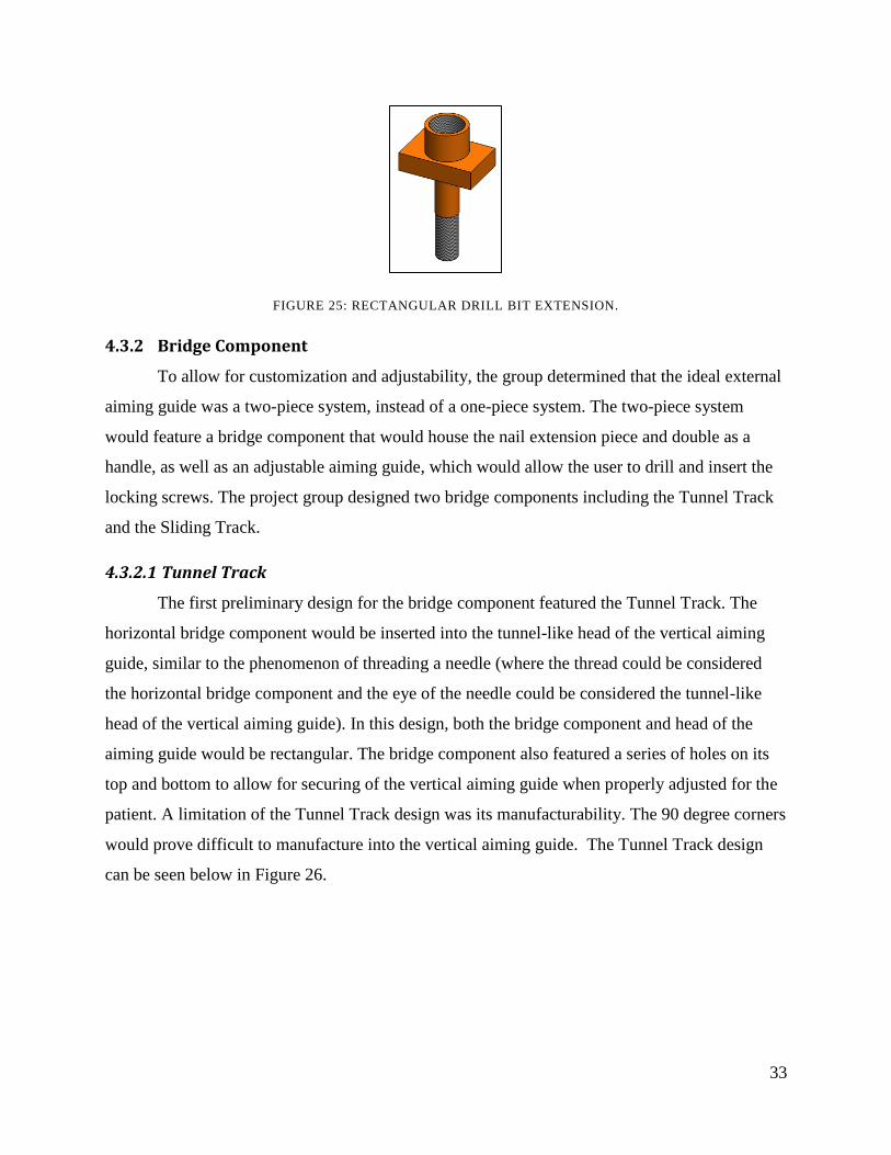
33
FIGURE 25: RECTANGULAR DRILL BIT EXTENSION.
4.3.2 Bridge Component
To allow for customization and adjustability, the group determined that the ideal external
aiming guide was a two-piece system, instead of a one-piece system. The two-piece system
would feature a bridge component that would house the nail extension piece and double as a
handle, as well as an adjustable aiming guide, which would allow the user to drill and insert the
locking screws. The project group designed two bridge components including the Tunnel Track
and the Sliding Track.
4.3.2.1 Tunnel Track
The first preliminary design for the bridge component featured the Tunnel Track. The
horizontal bridge component would be inserted into the tunnel-like head of the vertical aiming
guide, similar to the phenomenon of threading a needle (where the thread could be considered
the horizontal bridge component and the eye of the needle could be considered the tunnel-like
head of the vertical aiming guide). In this design, both the bridge component and head of the
aiming guide would be rectangular. The bridge component also featured a series of holes on its
top and bottom to allow for securing of the vertical aiming guide when properly adjusted for the
patient. A limitation of the Tunnel Track design was its manufacturability. The 90 degree corners
would prove difficult to manufacture into the vertical aiming guide. The Tunnel Track design
can be seen below in Figure 26.
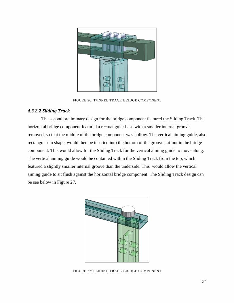
34
FIGURE 26: TUNNEL TRACK BRIDGE COMPONENT
4.3.2.2 Sliding Track
The second preliminary design for the bridge component featured the Sliding Track. The
horizontal bridge component featured a rectuangular base with a smaller internal groove
removed, so that the middle of the bridge component was hollow. The vertical aiming guide, also
rectangular in shape, would then be inserted into the bottom of the groove cut-out in the bridge
component. This would allow for the Sliding Track for the vertical aiming guide to move along.
The vertical aiming guide would be contained within the Sliding Track from the top, which
featured a slightly smaller internal groove than the underside. This would allow the vertical
aiming guide to sit flush against the horizontal bridge component. The Sliding Track design can
be see below in Figure 27.
FIGURE 27: SLIDING TRACK BRIDGE COMPONENT

35
4.3.3 Handle
To allow for a more ergonomic interlocking nail system, a handle was designed in order
to aid in the ease of use of the system. The project group designed three handles including the
Screw-On Handle, the Fully Tapered Handle, and the Tapered Handle.
4.3.3.1 Screw-On
A bridge component consisting of two pieces that are connected by threads would allow
for simple manufacturing while maintaining functionality. The first aspect of the bridge
component is the rectangular piece which has the track to allow for adjustment of the aiming
guide. This rectangular piece would have a female part with internal threads. The second aspect
of the bridge component is the handle which has a male part with external threads to securely
lock the two pieces together. The handle is intended to be ergonomic and is therefore rounded
similar to the handle of a bicycle. The Screw-On handle can be seen below in Figure 28.
FIGURE 28: SCREW-ON HANDLE
4.3.3.2 Fully Tapered
The design of the track to the handle of the bridge component is tapered to ease
manufacturing complications as seen below in Figure 29. The Tapered Handle is aesthetically
pleasing as well as ergonomic and keeps the number of parts minimal.

36
FIGURE 29: BRIDGE COMPONENT WITH FULLY TAPERED HANDLE
4.3.4 Bridge Connection Method
In order to connect the bridge component to the aiming guide, connection methods were
designed for the adjustability feature of the interlocking nail system. The project group designed
two connection methods including the Pin Connection, and the Locking Bolt Connection.
4.3.4.1 Pin Connection
Pin Connections, seen below in Figure 30, were designed to act as a locking mechanism
for the Tunnel Track as seen in Section4.3.2.1 Tunnel Track. Multiple pin hole options
seen in the Tunnel Track design allows the aiming guide to be adjusted to fit patients of different
sizes. It is important to have a secure locking mechanism to assure that the aiming guide cannot
be displaced once the surgeon has finalized its ideal position. If the connection is not secure, the
holes in the aiming guide will no longer be aligned with the holes of the nail. The Pin
Connections will not have proper functionality because they do not have a mechanism to prevent
them from sliding out of their intended positions in the bridge component.
FIGURE 30: PIN CONNECTION

37
4.3.4.2 Locking Bolts
Locking Bolts would be used as a locking mechanism for two different aspects of the
Gamma Guide design. Locking Bolts would act as a locking mechanism for the Sliding Track
design as seen in Section 4.3.2.2 Sliding Track. The Locking Bolts have a threaded male
piece that inserts into the female piece of the aiming guide, locking the bridge component to the
aiming guide. The Locking Bolts can be seen below in Figure 31.
FIGURE 31: LOCKING BOLT FOR CONNECTION TO AIMING GUIDE
The Locking Bolt will also be used to connect the drill bit piece to the bridge component. The
Locking Bolt will have a male threaded part, as seen below in Figure 32, which inserts into a
female threaded part of the drill pit piece.
FIGURE 32: LOCKING BOLT FOR CONNECTION TO BRIDGE COMPONENT
4.4 Preliminary Aiming Guide Designs
The aiming guide portion of the interlocking nail system dictates the success of the
system. Current systems lack in accuracy of insertion of the distal screws due to poor alignment
at the distal portion of the aiming guide. The aiming guide portion of the device must have a
solid connection the other portions of the device (the bridge component) because any
inaccuracies at the connection are exaggerated down the aiming guide and consequently distal

38
screw insertion is made difficult and inaccurate. The guide device, when fully assembled for use
in the operating room maybe turned at any degree with respect to upright assembly if not
horizontal for use and insertion into the patient since the patient will be horizontal or turned for
access to the bone/joint being operated on. For this reason, guide connection to the bridge
component needs to tight and strong enough to be manipulated in any direction according to the
surgeon‟s needs. For simplicity, the aiming guide should include aiming holes for multiple size
nail arranged and labeled in a clear, easy to read manner.
4.4.1 Aiming Vertical Piece
The project group designed the Tunnel Pin Vertical Piece to be used with the Pin
Connections described in Section 4.3.4.1 Pin Connection. The project group also designed
two Sliding Aiming Pieces to be used with the Locking Bolts as described in Section 4.4.1
Aiming Vertical Piece. These Aiming Vertical Piece Designs coupled with their
respective Connection Methods allows for the adjustability feature of the interlocking nail
system.
4.4.1.1 Double Rod Tunnel Pin
The tunnel-pin guide design includes an upper portion of the guide which will slide over
the bridge component with three locations of U-shaped pins to lock the guide into place as close
to the patient‟s limb as possible. This variation achieved by multiple pin hole options results in a
guide relevant for patients of all sizes without sacrificing accuracy of the system. Protruding
down from the connection is a pronged guide system with multiple holes corresponding to the
proximal and distal screw holes in the nail. The pronged system ensures a stable guide for use of
drilling and screw insertion sleeves while reducing material needed for the guide. At the bottom
of the aiming guide is an additional threaded hole which can hold a stabilization rod to further
increase the accuracy of the system. Pin Connections will make for easy assembly but may lack
in stability hold at different angles. In addition, the „tunnel‟ connection to the bridge component
may be difficult to manufacture due to the precise cuts and tight tolerances needed so as to
reduce movement and inaccuracy of the guide. The Double Rod Tunnel Pin aiming guide can be
seen below in Figure 33.
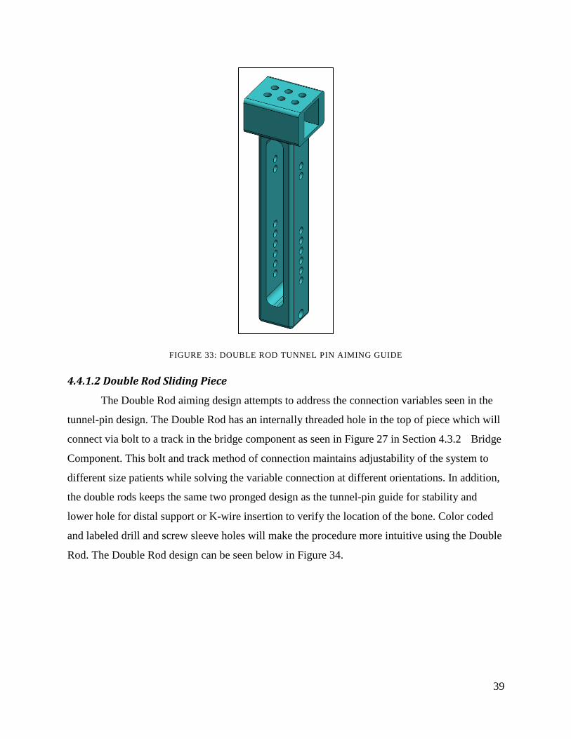
39
FIGURE 33: DOUBLE ROD TUNNEL PIN AIMING GUIDE
4.4.1.2 Double Rod Sliding Piece
The Double Rod aiming design attempts to address the connection variables seen in the
tunnel-pin design. The Double Rod has an internally threaded hole in the top of piece which will
connect via bolt to a track in the bridge component as seen in Figure 27 in Section 4.3.2 Bridge
Component. This bolt and track method of connection maintains adjustability of the system to
different size patients while solving the variable connection at different orientations. In addition,
the double rods keeps the same two pronged design as the tunnel-pin guide for stability and
lower hole for distal support or K-wire insertion to verify the location of the bone. Color coded
and labeled drill and screw sleeve holes will make the procedure more intuitive using the Double
Rod. The Double Rod design can be seen below in Figure 34.
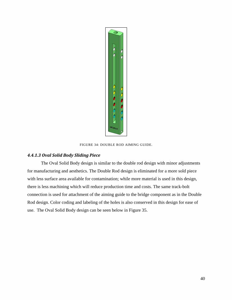
40
FIGURE 34: DOUBLE ROD AIMING GUIDE.
4.4.1.3 Oval Solid Body Sliding Piece
The Oval Solid Body design is similar to the double rod design with minor adjustments
for manufacturing and aesthetics. The Double Rod design is eliminated for a more sold piece
with less surface area available for contamination; while more material is used in this design,
there is less machining which will reduce production time and costs. The same track-bolt
connection is used for attachment of the aiming guide to the bridge component as in the Double
Rod design. Color coding and labeling of the holes is also conserved in this design for ease of
use. The Oval Solid Body design can be seen below in Figure 35.

41
FIGURE 35: OVAL SOLID BODY AIMING GUIDE
4.4.3 Drill/Bolt Sleeve
The Drill/Bolt Sleeve is used in the aiming guide in order to place locking screws
accurately into the interlocking nail. More specifically, the Drill/Bolt Sleeve assures that the
screws are perfectly aligned with pre-drilled holes.
4.4.3.1 Standard Drill/Bolt Sleeve
The Drill/Bolt Sleeves are inserted into the aiming guide holes in order to guide the
screws into the pre-drilled holes of the interlocking nail. The external diameter is fixed to fit the
guide holes while the internal diameter of different Drill/Bolt Sleeves can vary to accommodate
the different size screws needed for varying animal size. The Standard Drill/Bolt Sleeves can be
seen below in Figure 36.
FIGURE 36: SIDE VIEW OF STANDARD DRILL/BOLT SLEEVE.

42
4.4.4 Screw
The screw is an important aspect of the interlocking nail system as it fixates the
interlocking nail inside of the fractured bone. The screw must lock on both sides of the bone in
order to maintain proper fixation. The group considered the standard screw as well as a tapered
screw for this application.
4.4.4.1 Standard Screw
The Standard Screw consists to external threads wrapping around the cylindrical portion
of the screw. These threads provide a means of fixation; however, they limit surface contact with
the interlocking nail. The end of the screw is tapered to assist the ease of insertion. The Standard
Screw can be seen in Figure 37.
FIGURE 37: SIDE VIEW OF STANDARD SCREW
4.4.4.2 Tapered Screw
The Tapered Screw consists of two tapers on either end of the screw. These distal taper
assists the ease of insertion, while the proximal taper allows the screw to fit into the bone. Both
tapers are threaded in order to fixate the screws on either side of the fractured bone; however, the
cylindrical portion of the screw is not threaded in order to increase surface contact with the
interlocking nail. The Tapered Screw can be seen in Figure 38.
FIGURE 38: SIDE VIEW OF TAPERED SCREW
4.4.5 Distal Support
The distal supports were designed in order to contact the limb of interest during surgery.
These supports aid in aligning the aiming piece to the interlocking nail inside the medullary
canal and in proper screw insertion.

43
4.4.5.1 Distal Support Piece
The Distal Support Piece was designed to provide added support during surgery. This
piece is threaded through the bottom of the aiming guide and rests against the limb of the canine
during surgery. However, this piece is limited to the exterior of the limb and does not provide a
means for locating the actual fractured bone inside of the limb. The Distal Support Piece can be
seen below in Figure 39.
FIGURE 39: DISTAL SUPPORT
4.4.5.2 K-Wire
The K-Wire is a very small wire that is placed through the bottom of the aiming guide to
aid in support and alignment during surgery. Unlike the Distal Support Piece, the K-Wire can
puncture the skin of the fractured limb and contact the bone inside of the limb. This will ensure
that the aiming guide is aligned with the interlocking nail for proper screw insertion. The K-Wire
can be seen below.

44
FIGURE 40: K-WIRE
4.5 Final Nail Design
After reviewing the preliminary nail designs for the Gamma Guide, the project group
designed the final limited contact nail and connection method. These components of the device
were designed to address the limitations of preliminary nail designs.
4.5.1 Limited Contact
The final limited contact nail design selected by the project group is a variation of the
Circular Groove Pattern described below.
4.5.1.1 Circular Groove Pattern
The final limited contact design was based upon the preliminary concepts developed in
the Circular Groove Pattern design as seen in Section 4.2.1 Limited Contact. The final nail
design has a limited contact feature which is achieved by material being removed between holes
to reduce nail to bone contact. The first preliminary design of the circular groove patterned nail
included five nail to bone contact points. The second preliminary design had fourteen nail to
bone contact points. It was important to find a balance between the two preliminary designs to
have a nail with enough grooves to have the limited contact be significant but also have enough
contact points to ensure stability. The cross section of the final nail design can be seen below in
Figure 41.

45
FIGURE 41: CROSS SECTION OF CIRCULAR GROOVE PATTERN
4.5.2 Connection Method
The final connection method design selected by the project group is the Internal Thread
Connection that is described below.
4.5.2.1 Internal Thread Connection
The Internal Thread Connection of the guide to the nail design is intended to simplify the
connection point and ensure easy manufacturing of the components. Unlike the internal track
needed for the Turn Key Connection, milling of internal threads is a common and standard
manufacturing practice; standard thread sizes can be used to produce a tight connection that will
precisely align the screw hole with the guide. In addition, the Internal Thread Connection will be
able to withstand adjustment of the nail and guide during insertion and provide a strong
connection for emergency extraction. Once the nail is inserted into the bone, the attachment can
be unscrewed. This mechanism is a familiar motion for surgeons as compared to the custom
track design described in Section 4.2.2 Connection Method or
similar custom nail-guide attachment techniques. The Internal Thread can be seen below in
Figure 42.

46
FIGURE 42: INTERNAL THREAD CONNECTION
4.6 Final Nail Insertion Design
After reviewing the preliminary nail insertion designs for the Gamma Guide, the project
group designed the final drill bit extension piece, the bridge component, the handle, and the
bridge connection method. These components of the device were extracted from the preliminary
nail insertion designs or were designed to address their limitations.
4.6.1 Drill Bit Extension
The final drill bit extension design selected by the project group is the Elliptical Drill Bit
Extension described below.
4.6.1.1 Elliptical Drill Bit Extension
The final nail insertion design was inspired by the Circular and Rectangular Drill Bit
Extension Pieces. The Circular Bit would allow for rotation of the piece when fastening the
device prior to nail insertion. The Rectangular Drill Bit would be difficult to manufacture in
terms of the actual rectangle on the Drill Bit as well as the rectangular cut out in the Aiming
Guide. Based on the problems foreseen with the Circular and Rectangular Drill Bits, the third
evolution of the nail extension piece was created. Similar to both the Circular and Rectangular
Drill Bits, the Elliptical Drill Bit features the same “key” locking mechanism and male and
female thread components. In addition, the Elliptical Drill Bit features a thicker “body” which
allows for proper securing of the nail extension piece into the nail. This body features a slightly
larger diameter than that of the male threaded component, allowing for easy recognition for

47
when the nail extension piece and nail are properly fastened. The larger diameter body also takes
up part of the load which would normally be distributed to the male threads in previous designs.
In addition, the elliptical female slot in the corresponding connection piece would be
manufacturable, since it does not contain any 90 degree angles. The Elliptical Drill Bit can be
seen below in Figure 43.
FIGURE 43: ELLIPTICAL DRILL BIT EXTENSION PIECE
4.6.2 Bridge Component
The final bridge component design selected by the project group is the Sliding Track that
was described above in Section 4.3.2.2 Sliding Track.
4.6.2.1 Sliding Track
The Sliding Track is the first of the project group‟s preliminary designs to be
implemented into the final design. Several variations of the Sliding Track‟s complementary
aiming vertical piece were designed however, and will be thoroughly explained in Section
4.4.1.2 Double Rod Sliding Piece and Section 4.4.1.3 Oval Solid Body Sliding Piece. The
Sliding Track can be seen above in Figure 27.
4.6.3 Handle
The final handle design selected by the group is the Tapered Handle described below.

48
4.6.3.1 Tapered Handle
The design of a bridge component consisting of one piece, like the one above in Figure
29: was modified with a shorter taper for easier manufacturing as seen below in Figure 44. The
fillets on the handle are intended to accomplish this.
FIGURE 44: BRIDGE COMPONENT WITH PARTIALLY TAPERED HANDLE
4.6.4 Bridge Connection Method
The final bridge connection method design selected by the project group is the Locking
Bolt that was described above in Section 4.3.4.2 Locking Bolts.
4.5.2.1 Locking Bolts
The Locking Bolts were the second of the project group‟s preliminary designs to be
implemented into the final design. The Locking Bolts can be seen above in Figure 31 and Figure
32.
4.7 Final Aiming Guide Design
After reviewing the preliminary nail designs for the Gamma Guide, the project group
designed the final sliding aiming piece, the drill/bolt sleeve, the screw, and the distal support.
These components of the device were extracted from the preliminary aiming guide designs or
were designed to address their limitations.
4.7.1 Sliding Aiming Piece
The final sliding aiming piece design selected by the project group is the Squared Solid
Body Design described below.
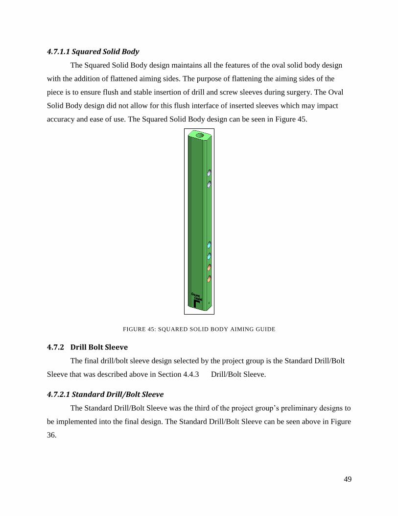
49
4.7.1.1 Squared Solid Body
The Squared Solid Body design maintains all the features of the oval solid body design
with the addition of flattened aiming sides. The purpose of flattening the aiming sides of the
piece is to ensure flush and stable insertion of drill and screw sleeves during surgery. The Oval
Solid Body design did not allow for this flush interface of inserted sleeves which may impact
accuracy and ease of use. The Squared Solid Body design can be seen in Figure 45.
FIGURE 45: SQUARED SOLID BODY AIMING GUIDE
4.7.2 Drill Bolt Sleeve
The final drill/bolt sleeve design selected by the project group is the Standard Drill/Bolt
Sleeve that was described above in Section 4.4.3 Drill/Bolt Sleeve.
4.7.2.1 Standard Drill/Bolt Sleeve
The Standard Drill/Bolt Sleeve was the third of the project group‟s preliminary designs to
be implemented into the final design. The Standard Drill/Bolt Sleeve can be seen above in Figure
36.

50
4.7.3 Screw
The final screw design selected by the project group is Tapered Screw that was described
above in Section 4.5.3.1 Tapered Screw.
4.5.3.1 Tapered Screw
The Tapered Screw was the fourth of the group‟s preliminary designs to be implemented
into the final design. The Tapered Screw can be seen above in Figure 38.
4.7.4 Distal support
The final distal support design selected by the project group is K-Wire that was described
above in Section 4.4.5.2 K-Wire.
4.7.4.1 K-Wire
The K-Wire was the fifth of the project group‟s preliminary designs to be implemented
into the final design. The K-Wire can be seen above in Figure 40.
4.8 Evaluation of Final Design
The final assembled design can be seen below in Figure 46. This assembly features the
final nail components including the Circular Groove Pattern nail and Internal Thread
Connection, the final nail insertion components including the Elliptical Drill Bit Extension, the
Sliding Track, the Tapered Handle, and the Locking Bolts, and the final aiming guide
components including the Squared Solid Body, the Standard Drill/Bolt Sleeve, the Tapered
Screw, and the K-Wire.

51
FIGURE 46: FINAL DESIGN ASSEMBLY
Each of these components contributes to addressing the limitations that were described in
Section 2.3.4 Limitations and Section 4.1 Limitations of Current Device. In terms of
biocompatibility, the Gamma Guide addresses the limitations of the existing interlocking nail
system including the material properties of the nail and nail contact in the medullary cavity. In
addition, the Gamma Guide‟s nail and tapered bolts will be manufactured using titanium, as the
mechanical properties of titanium are closer to that of bone. Additionally, titanium has favorable
properties for imaging and osteointegration as described in Section 2.3.4.1 Material Properties.
The Finally, the Gamma Guide‟s limited contact nail allows for increased blood flow through the
medullary cavity and proper healing as described in Section 2.3.4.2 Nail to Bone Contact.
Furthermore, the Gamma Guide addresses limitations regarding the ease of use of the
existing interlocking nail system. These limitations include device complexity and distal
targeting. The Gamma Guide eliminates the need for an array of aiming components for varying
canine size as the aiming component is adjustable. This will allow the veterinary surgeons to use
one aiming guide for all canine sizes. Additionally, the Gamma Guide address the limitation of
distal targeting in a variety of ways. The design features the K-Wire which allows the veterinary
surgeons to confirm contact with bone and ensure proper alignment before screw insertion.
Secondly, the Gamma Guide nail features countersunk holes to aid in the ease of screw insertion.
Lastly, tapered bolts will be used to further assist distal screw insertion.

52
4.9 Modeling
The project group used two techniques, the computer software, SolidWorks (2010), and
3-D rapid prototyping to model their design throughout the design process. These two techniques
are described below.
4.9.1 Computer Aided Design (CAD)
Preliminary modeling of designs was done via the computer software SolidWorks (2010).
The assembly feature of the program allowed the combination of components with differing
designs to be examined in terms of their relationship to the remaining components of the device
before further modeling was done. Figure 47 displays the SolidWorks Assembly feature which
allowed for the described verification of part sizes and functionality with other components.
Ensuring proper sizing and aesthetics using this software, the group then proceeded to further
modeling of complete design prototypes.
FIGURE 47: SOLIDWORKS ASSEMBLY OF COMPONENTS
53
4.9.2 3-D Rapid Prototyping
The main goal of creating models using the Rapid Prototyping machine was to explore
design concepts quickly and affordably. The technology allows for enhancing visualization and
verification of design parts. The RP machine prints models in acrylonitrile butadiene styrene
(ABS) plastic. The technology constructs physical models from Computer-Aided Design (CAD)
data. The data retrieved from the CAD software, SolidWorks, are converted into STL format.
The STL file is sliced into thin cross-sectional layers. The model is constructed on layer atop
another from polymers, paper, or powdered metal (22). Finally the model is finished and cleaned.
This involves removing the prototype from the machine and detaching any supports (22).
Two prototypes were created including the initial preliminary design along with the
reiterated design. The following sequence was used as a practical method for improving the
quality of products (23):
1. Design the prototype using CAD.
2. Build the prototype with RP.
3. Inspect the RP parts for error
4. Correct errors found in CAD.
5. Verify the corrected RP part.
6. Iterate, using RP, to improve the design.
7. When acceptable, build a functional test model.
8. Perform functional testing.
9. When satisfactory, proceed to manufacture.
Each component of the final Gamma Guide was created using the RP machine including
the nail, drill bit piece, locking components, track, handle, aiming guide, and drill sleeve. The
two models that were created were used for comparison purposes in deciding the components of
the final design. By using the technology, the group was able to have functional models that
assisted with reiterations as well as keeping costs minimal prior to the manufacturing of the final
design. The prototypes served as excellent visual aids for communicating ideas with the group‟s
advisor, sponsor, and machinists.
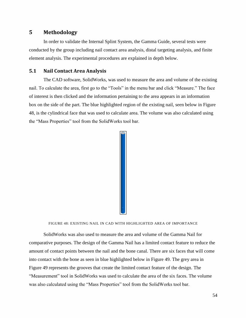
54
5 Methodology
In order to validate the Internal Splint System, the Gamma Guide, several tests were
conducted by the group including nail contact area analysis, distal targeting analysis, and finite
element analysis. The experimental procedures are explained in depth below.
5.1 Nail Contact Area Analysis
The CAD software, SolidWorks, was used to measure the area and volume of the existing
nail. To calculate the area, first go to the “Tools” in the menu bar and click “Measure.” The face
of interest is then clicked and the information pertaining to the area appears in an information
box on the side of the part. The blue highlighted region of the existing nail, seen below in Figure
48, is the cylindrical face that was used to calculate area. The volume was also calculated using
the “Mass Properties” tool from the SolidWorks tool bar.
FIGURE 48: EXISTING NAIL IN CAD WITH HIGHLIGHTED AREA OF IMPORTANCE
SolidWorks was also used to measure the area and volume of the Gamma Nail for
comparative purposes. The design of the Gamma Nail has a limited contact feature to reduce the
amount of contact points between the nail and the bone canal. There are six faces that will come
into contact with the bone as seen in blue highlighted below in Figure 49. The grey area in
Figure 49 represents the grooves that create the limited contact feature of the design. The
“Measurement” tool in SolidWorks was used to calculate the area of the six faces. The volume
was also calculated using the “Mass Properties” tool from the SolidWorks tool bar.
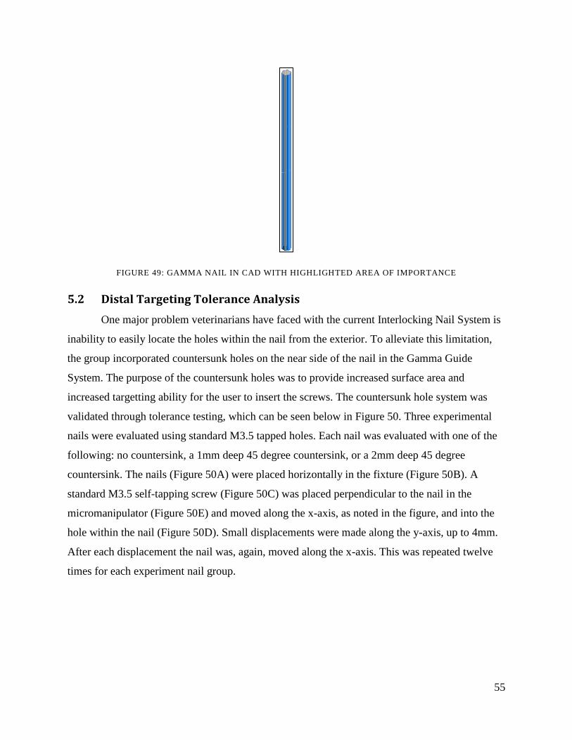
55
FIGURE 49: GAMMA NAIL IN CAD WITH HIGHLIGHTED AREA OF IMPORTANCE
5.2 Distal Targeting Tolerance Analysis
One major problem veterinarians have faced with the current Interlocking Nail System is
inability to easily locate the holes within the nail from the exterior. To alleviate this limitation,
the group incorporated countersunk holes on the near side of the nail in the Gamma Guide
System. The purpose of the countersunk holes was to provide increased surface area and
increased targetting ability for the user to insert the screws. The countersunk hole system was
validated through tolerance testing, which can be seen below in Figure 50. Three experimental
nails were evaluated using standard M3.5 tapped holes. Each nail was evaluated with one of the
following: no countersink, a 1mm deep 45 degree countersink, or a 2mm deep 45 degree
countersink. The nails (Figure 50A) were placed horizontally in the fixture (Figure 50B). A
standard M3.5 self-tapping screw (Figure 50C) was placed perpendicular to the nail in the
micromanipulator (Figure 50E) and moved along the x-axis, as noted in the figure, and into the
hole within the nail (Figure 50D). Small displacements were made along the y-axis, up to 4mm.
After each displacement the nail was, again, moved along the x-axis. This was repeated twelve
times for each experiment nail group.

56
FIGURE 50: TOP VIEW OF TOLERANCE TESTING SET UP
The micromanipulator (tripod stand) was used for its ease of adjustability in leg height as
well as translation motion for the self-tapping screw. The screw was used as a representation of
the screw that would normally be inserted through the drill sleeve and into the nail in the actual
interlocking nail system. The experimental brass nails were constructed in the machine shop in
Higgins Laboratory at WPI. The nails featured grooved cut outs to match the limited contact
feature of the nail designed for the actual system. The three different holes were important for
comparative testing of which hole would be the most effective in terms of optimizing screw
insertion accuracy.
5.3 Finite Element Analysis
Finite element analysis (FEA) was used to calculate approximate plastic deformation
torsional loads both in the group‟s novel limited contact nail design (Gamma Nail) as well as the
in design of the nail currently on the market (Existing Nail). In addition, the FEA provided
qualitative insight into stress concentration variation due to nail shape and material choice. The
SIMULATION application in SolidWorks 2010 Office Products was used to run static torsional
load simulations modeled after experimental Instron testing. Stress concentrations were reported
in Von Mises Stress (equivalent stress) and stress concentration location was visually analyzed.
Nail variables tested included shape and material: the fundamental changes made in the
design of the Gamma Nail. The Gamma Nail is designed for limited contact (shape change) and
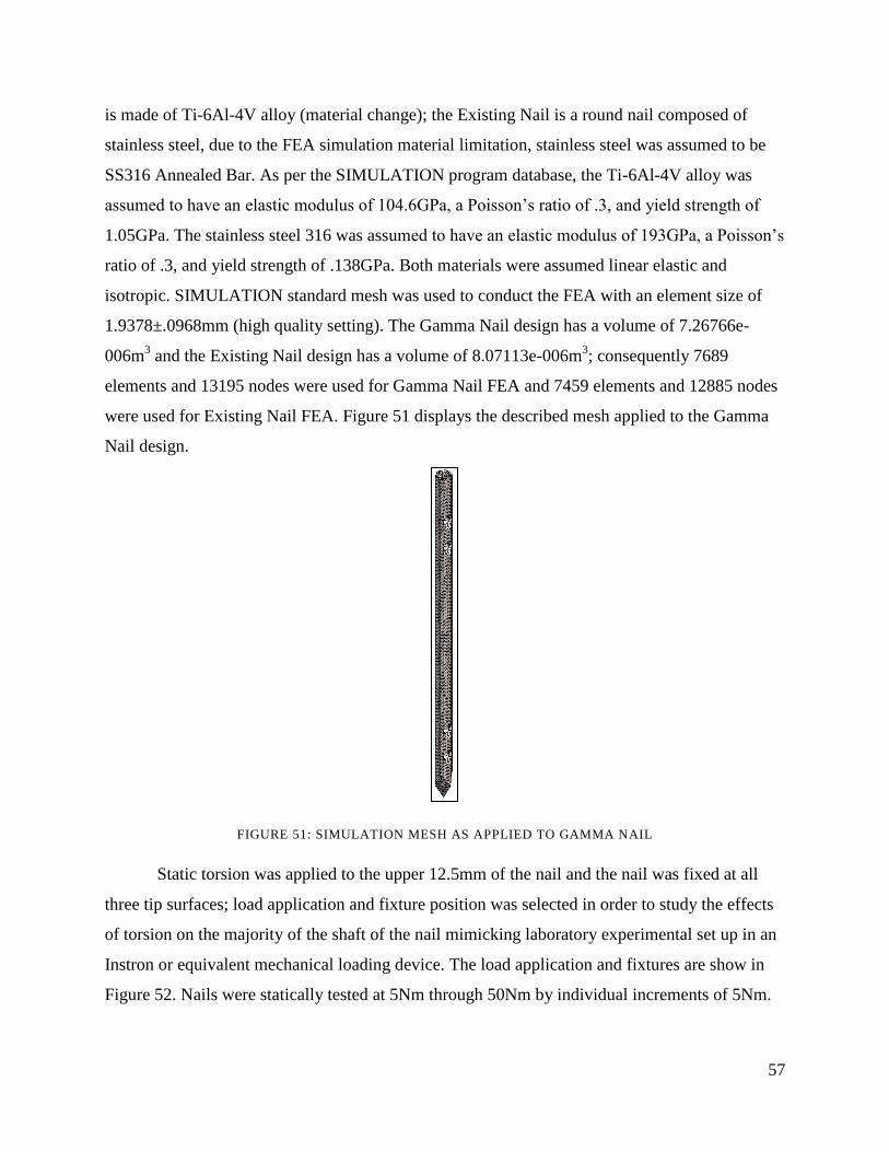
57
is made of Ti-6Al-4V alloy (material change); the Existing Nail is a round nail composed of
stainless steel, due to the FEA simulation material limitation, stainless steel was assumed to be
SS316 Annealed Bar. As per the SIMULATION program database, the Ti-6Al-4V alloy was
assumed to have an elastic modulus of 104.6GPa, a Poisson‟s ratio of .3, and yield strength of
1.05GPa. The stainless steel 316 was assumed to have an elastic modulus of 193GPa, a Poisson‟s
ratio of .3, and yield strength of .138GPa. Both materials were assumed linear elastic and
isotropic. SIMULATION standard mesh was used to conduct the FEA with an element size of
1.9378±.0968mm (high quality setting). The Gamma Nail design has a volume of 7.26766e-
006m3 and the Existing Nail design has a volume of 8.07113e-006m
3; consequently 7689
elements and 13195 nodes were used for Gamma Nail FEA and 7459 elements and 12885 nodes
were used for Existing Nail FEA. Figure 51 displays the described mesh applied to the Gamma
Nail design.
FIGURE 51: SIMULATION MESH AS APPLIED TO GAMMA NAIL
Static torsion was applied to the upper 12.5mm of the nail and the nail was fixed at all
three tip surfaces; load application and fixture position was selected in order to study the effects
of torsion on the majority of the shaft of the nail mimicking laboratory experimental set up in an
Instron or equivalent mechanical loading device. The load application and fixtures are show in
Figure 52. Nails were statically tested at 5Nm through 50Nm by individual increments of 5Nm.

58
The Gamma Nail design and the Current Nail design were tested using both Ti-6Al-4V and
SS316 to isolate the shape and material variables on the resultant FEA stress results.
FIGURE 52: TORSIONAL LOAD APPLICATION (PINK) AND NAIL TIP FIXTURE SURFACES (GREEN AND
BLUE)
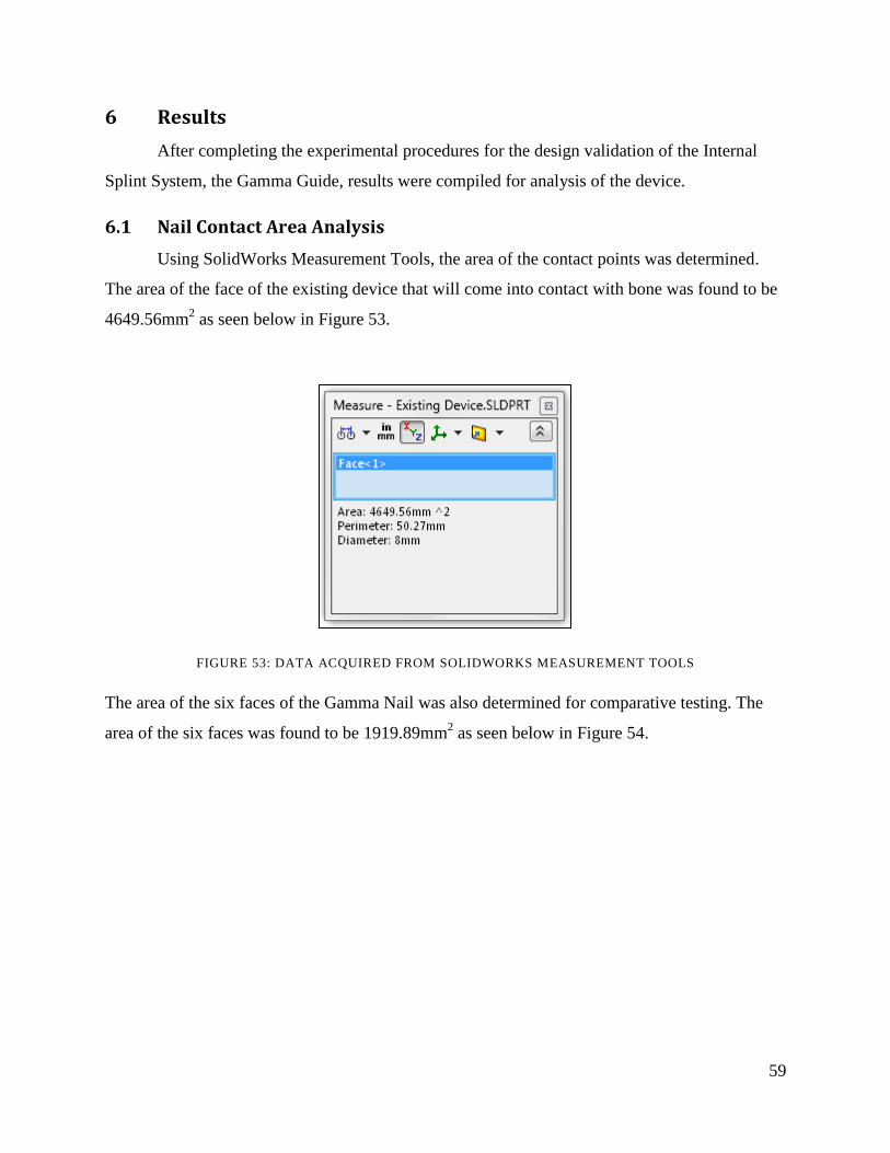
59
6 Results
After completing the experimental procedures for the design validation of the Internal
Splint System, the Gamma Guide, results were compiled for analysis of the device.
6.1 Nail Contact Area Analysis
Using SolidWorks Measurement Tools, the area of the contact points was determined.
The area of the face of the existing device that will come into contact with bone was found to be
4649.56mm2 as seen below in Figure 53.
FIGURE 53: DATA ACQUIRED FROM SOLIDWORKS MEASUREMENT TOOLS
The area of the six faces of the Gamma Nail was also determined for comparative testing. The
area of the six faces was found to be 1919.89mm2 as seen below in Figure 54.

60
FIGURE 54: DATA ACQUIRED FROM SOLIDWORKS MEASUREMENT TOOL FOR GAMMA SYSTEM
To determine the decrease in area of nail to bone contact between the existing device and
the Gamma Nail, percent change was found using the equation seen below:
(
)
The percent change was calculated by plugging in the values found for the area of the existing
nail and the area of the gamma nail in mm2. Based on these calculations, there was a 58.7%
decrease in the area of the nail that comes into contact with the bone of the Gamma Nail
compared to the existing nail as seen below.
TABLE 1: PERCENT CHANGE VALUE BETWEEN THE EXISTING NAIL AND THE GAMMA NAIL
Area of Existing Nail (mm^2) Area of Gamma Nail (mm^2) Percent Change (%)
4649.56 1919.89 58.7

61
The volume the existing device was found to be 9299.11 mm3
based on the data provided
using the Measurement tool in SolidWorks as seen below in Figure 55.
FIGURE 55: MASS PROPERTIES DATA COLLECTED USING SOLIDWORKS OF THE EXISTING NAIL
The volume of the Gamma Nail was found to be 8394.49 mm3
based on the data provided
using the Measurement tool in SolidWorks as seen below in Figure 56.

62
FIGURE 56: MASS PROPERTIES DATA COLLECTED USING SOLIDWORKS OF THE GAMMA NAIL
The percent change values were also calculated to determine the difference in the volume
between the existing nail and the Gamma Nail. The volume decreased by 10% when the limited
contact feature was implemented into the design of the nail.
TABLE 2: PERCENT CHANGE HIGHLIGHTING THE CHANGE IN VOLUME
Volume of Existing Nail (mm^2) Volume of Gamma Nail (mm^2) Percent Change (%)
9299.11 8359.27 10.1
6.2 Distal Targeting Tolerance Analysis
Raw data from the tolerance test can be seen below in Tables 2,3, and 4. Each table
displays the measure of displacement from the center of the screw (far left column), followed by
the results for each test subject. “Yes” denotes that the nail successfully entered the hole, while
“No” denotes that the nail did not successfully enter the hole.

63
TABLE 3: TOLERANCE TESTING DATA OF NONCOUNTERSUNK HOLE
Distance from
Center of Hole
(mm)
Screw Enters
Hole Subject
#1
Screw Enters
Hole Subject #2
Screw Enters
Hole Subject #3
Screw Enters
Hole Subject #4
0 Yes Yes Yes Yes
1 Yes Yes Yes Yes
2 No No No No
3 No No No No
4 No No No No
TABLE 4: TOLERANCE TESTING DATA OF 1MM COUNTERSUNK HOLE
Distance from
Center of Hole
(mm)
Screw Enters
Hole Subject
#1
Screw Enters
Hole Subject #2
Screw Enters
Hole Subject #3
Screw Enters
Hole Subject #4
0 Yes Yes Yes Yes
1 Yes Yes Yes Yes
2 Yes Yes Yes Yes
3 No No No No
4 No No No No
TABLE 5: TOLERANCE TESTING DATA OF 2MM COUNTERSUNK HOLE
Distance from
Center of Hole
(mm)
Screw Enters
Hole Subject
#1
Screw Enters
Hole Subject #2
Screw Enters
Hole Subject #3
Screw Enters
Hole Subject #4
0 Yes Yes Yes Yes
1 Yes Yes Yes Yes
2 Yes Yes Yes Yes
3 Yes Yes Yes Yes
4 No No No No
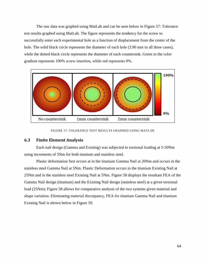
64
The raw data was graphed using MatLab and can be seen below in Figure 57: Tolerance
test results graphed using MatLab. The figure represents the tendency for the screw to
successfully enter each experimental hole as a function of displacement from the center of the
hole. The solid black circle represents the diameter of each hole (3.90 mm in all three cases),
while the dotted black circle represents the diameter of each countersink. Green in the color
gradient represents 100% screw insertion, while red represents 0%.
FIGURE 57: TOLERANCE TEST RESULTS GRAPHED USING MATLAB
6.3 Finite Element Analysis
Each nail design (Gamma and Existing) was subjected to torsional loading at 5-50Nm
using increments of 5Nm for both titanium and stainless steel.
Plastic deformation first occurs at in the titanium Gamma Nail at 20Nm and occurs in the
stainless steel Gamma Nail at 5Nm. Plastic Deformation occurs in the titanium Existing Nail at
25Nm and in the stainless steel Existing Nail at 5Nm. Figure 58 displays the resultant FEA of the
Gamma Nail design (titanium) and the Existing Nail design (stainless steel) at a given torsional
load (25Nm); Figure 58 allows for comparative analysis of the two systems given material and
shape variation. Eliminating material discrepancy, FEA for titanium Gamma Nail and titanium
Existing Nail is shown below in Figure 59.
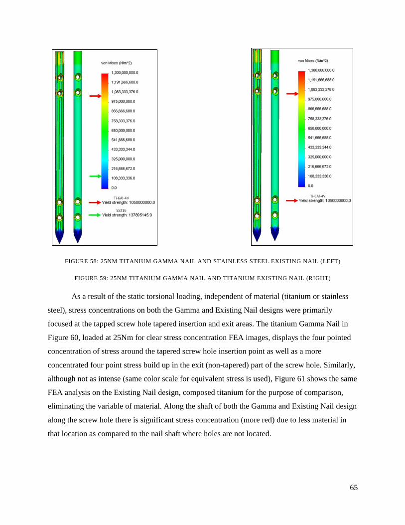
65
FIGURE 58: 25NM TITANIUM GAMMA NAIL AND STAINLESS STEEL EXISTING NAIL (LEFT)
FIGURE 59: 25NM TITANIUM GAMMA NAIL AND TITANIUM EXISTING NAIL (RIGHT)
As a result of the static torsional loading, independent of material (titanium or stainless
steel), stress concentrations on both the Gamma and Existing Nail designs were primarily
focused at the tapped screw hole tapered insertion and exit areas. The titanium Gamma Nail in
Figure 60, loaded at 25Nm for clear stress concentration FEA images, displays the four pointed
concentration of stress around the tapered screw hole insertion point as well as a more
concentrated four point stress build up in the exit (non-tapered) part of the screw hole. Similarly,
although not as intense (same color scale for equivalent stress is used), Figure 61 shows the same
FEA analysis on the Existing Nail design, composed titanium for the purpose of comparison,
eliminating the variable of material. Along the shaft of both the Gamma and Existing Nail design
along the screw hole there is significant stress concentration (more red) due to less material in
that location as compared to the nail shaft where holes are not located.

66
FIGURE 60: 25NM TITANIUM GAMMA NAIL STRESS CONCENTRATION (LEFT)
FIGURE 61: 25NM TITANIUM EXISTING NAIL STRESS CONCENTRATION (RIGHT)
Stress concentration along the shaft due to shape variation between the nail designs is
also demonstrated by SIMULATION finite element analysis. Figure 62 shows shafts of both the
Existing and Gamma Nail designs subjected to 25Nm.
FIGURE 62: 25NM TITANIUM GAMMA (LEFT) AND EXISTING (RIGHT) NAIL DESIGNS

67
7 Discussion
After compiling the results from the experimental procedures to validate the Internal
Splint System, the Gamma Guide, the results were thoroughly analyzed to ensure validity of the
design.
7.1 Nail Contact Area Analysis
The limited contact feature of the Gamma Nail is intended to preserve blood supply. In
order to do so, the points of contact between the nail and the medullary cavity of the bone must
be reduced. The design of the grooves in the Gamma Nail was intended to reduce the nail to
bone contact by approximately 50%. The area of the nail to bone contact points was evaluated
between the existing nail and the Gamma Nail using the SolidWorks measurement tool. The
actual reduction in the nail to bone contact area was 58.7%. This reduction in bone to nail
contact area suggests that vascular damage will be minimized with the limited contact feature of
the Gamma Nail. This should lead to a more versatile and efficient application of internal
fixation of femoral fractures using nails.
7.2 Distal Targeting Tolerance Analysis
From the raw data, it is evident that the experimental group that contained the non-
countersunk hole provided the least tolerance for screw insertion, as it only allowed for
successful screw insertion at a distance of 1 mm from the center of the hole. The 1 mm
countersink group provided greater tolerance, up to 2 mm from the center of the hole, accounting
for a 100% increase as compared to the non-countersink group. The 2 mm countersink group,
however, provided the greatest tolerance for screw insertion at 3 mm from the center of the hole.
This contributes to a 150% increase as compared to the 1 mm deep countersink group and a
300% increase as compared to the non-countersink group.
The MatLab figure shows the same data as the tables, but provides an easier means for
comprehension. It is clearly evident that the area that provides 100% successful screw insertion
is greatest in the 2mm deep countersink group. In addition, it is evident that the total area for
screw insertion (denoted by the diameter of the dotted black circle), is greatest in the 2mm deep
countersink group.

68
While it was anticipated by the group that the 2mm deep countersink group would
provide the greatest tolerance for screw insertion, the increase in targeting ability was largely
unknown. The tolerance test provided a means for the group to characterize the tolerance for
screw insertion for each experimental group by both quantitative and qualitative means. This was
significant for the validation of the final design.
The increase in tolerance corresponds to an increased surface area and ultimately, an
increased targeting ability for screw insertion by the surgeon. The increased targeting ability
addresses one of the major limitations of the existing device and helps ensure that the surgery is
successful.
7.3 Finite Element Analysis
There are numerous studies investigating interlocking nail systems designed for human
fracture fixation. These studies typically examine cyclic torsion and four point bending applied
to the bone-nail-screw complete interlocking nail system. Testing is done on the complete system
due to the complexity of the loading in vivo and usual modes of failure which include bone-
screw-nail combined failure at the component interfaces rather than a single component
individually failing. Computer generated studies conducted on the Gamma Nail design and the
Existing Nail design are limited in respect to experimental studies done using complete systems
in a laboratory setting; due to the limitations of the SIMULATION software, only individual
components could be run through the FEA (complete systems of bone-nail-screw cannot be run
in the SIMULATION program). However, because of budget and manufacturing limitations, the
FEA analysis provides a reasonable study comparative within itself of the effects of torsion on
the nail designs given load, shape, and material variation.
Stress concentration around the screw hole insertion and exit points is apparent in both
the Gamma and Existing Nail designs. As show in Figure 60 and Figure 61, at a 25Nm static
load, there is a four pointed build-up of stress at the tapered insertion point and a more compact
four point stress build up at the exit area of the screw hole in both nail designs. Similarly, along
the shaft where the holes are located, there is a thin strip of stress concentration; this is due to the
reduced amount of material at these locations. Because grooves cut along the shaft of the Gamma
Nail there is an increase in stress build up both at the taper and exit areas of the screw hole in the
Gamma Nail design. This is to be expected due to the reduced material at these locations in
69
addition to the abrupt changes in contour at the nail surface. A 25Nm torsional load was used to
clearly demonstrate the stress concentration areas in both nail designs; however, the literature
suggests that at 20+Nm loading, the screw-bone interface will fail before the nail can deform.
Bone is generally weak in torsion and fails at approximately 55MPa: orders of magnitude lower
than the yield stress of Ti-6Al-4V. Essentially, while there is increased concentration of stress
due to the grooves of the Gamma Nail compared to the uniformly round Existing Nail, these
stress build ups are comparable and both well within the elastic deformation range at torsional
loads under 20Nm.
The Gamma and Existing Nail designs differ in one fundamental shape change: the
Gamma design has grooves cut down the shaft to reduce contact with the native bone cavity. As
shown in Figure 62, the grooved portions of the Gamma Nail have slightly higher stress
concentration than the rest of the shaft. However, when compared to the Existing Nail which has
a uniform stress load on the shaft, the stress gradient in the Gamma Nail averages to
approximately the loading experienced by the Existing Nail. Because of the relatively small,
although present, stress gradient it is difficult to extrapolate from the FEA imaging the increase
in equivalent stress exhibited in the grooves of the Gamma Nail. However, even at 25Nm as
show in Figure 62, stress exhibited on the shaft of both nail designs is well below the yield
strength of titanium; this is even more apparent at lower, more realistic torsional loads.
7.4 Impact of Gamma Guide System
While the group believes that the Internal Splint System, the Gamma Guide, will have an
immeasurable impact on fracture fixation in canines, the group realizes that impacts on other
factors such as economics, politics, ethics, the environment, and manufacturability.
7.4.1 Economic Impact
As previously discussed, veterinary expenditures have been on the rise over the past
decade and are projected to further increase over the next five years. In addition, as stated in the
literature and in interviews with veterinary orthopedic surgeons, pet owners are willing to spend
large amounts of money on veterinary care to prolong the lives of their pets. Because pet owners
are so invested in the health of their pets, there is large market demand for veterinary care
products that improve quality of life. More specifically, devices for fracture fixation in canines
are highly important as fractures are a very common injury in canines. The design of a device to

70
improve the treatment of fractures will be advantageous for not only the canine but for the
economy as well.
7.4.2 Political Ramifications
Political ramifications must also be considered in the design of the Internal Splint
System, the Gamma Guide, as clinical testing must be completed prior to the marketing of the
device. Clinical testing involves the use of animals which is a controversial topic in scientific
research, especially veterinary research. Organizations such as People for the Ethical Treatment
of Animals (PETA) fight for the humane treatment of animals during product development,
experimentation, and research. In order to avoid difficulty with PETA and organizations alike,
protocols for the humane treatment of animals during experimentation must be followed and
animal testing should be kept to a minimum as this procedure is currently practiced in veterinary
care.
7.4.3 Ethical Concerns
Ethical concerns in regards to the canine‟s health and safety must be noted as canines are
directly affected by the experimental procedure and redesigned system, the Gamma Guide.
Because the existing nail occupies the entirety of the medullary canal, blood flow can be limited
and bone tissue necrosis or infection can arise. As a result of this, the canine will be subjected to
a secondary procedure to remove the nail from patient causing trauma and additional pain to the
canine. The group hopes by incorporating a limited contact nail into the design, the rate of bone
necrosis and infection will be significantly decreased due to increased blood flow to the native
tissue and the canine will not be subjected to additional procedures.
7.4.4 Environmental Impact
Environmental impact of the Gamma Guide is important as there are many current
movements around the world to limit resources and become a “greener” planet. As previously
mentioned, the group hopes that by adding a limited contact nail to the design, the group will be
able to significantly limit the number of secondary procedures to remove the nail. By limiting the
number of repeat procedures, many resources will be conserved and resources used in the
primary procedure will not be wasted. An example of these resources includes surgical tools that
will be disposed of upon completion of the procedure.
71
7.4.5 Manufacturability
Finally, the group considered manufacturability when designing the Internal Splint
System, the Gamma Guide. Throughout the design process the group remained in contact with
Neil Whitehouse at the WPI machine shop in addition to Harry Wotton to ensure that each
component of the group‟s design was easy to manufacture. Though the redesigned system is
composed of slightly more elaborate components such as the sliding track and limited contact
nail, the group ensures that the advantages to these pieces greatly outweigh the increased
manufacturing time. Furthermore, after talking to Harry Wotton, he remained confident that each
part of the device was easy to manufacture at SECUROS.

72
8 Conclusion
In concluding the group‟s approach to this design problem, we have developed a new
system for internal splinting for canine fracture fixation. By initially addressing problems with
the current Interlocking Nail System in addition to fundamental technology limitations identified
by practicing veterinarians, improvements were made to revitalize the technology of internal
splinting. The newly designed Gamma Guide has the ability to improve the overall success of the
current procedure by means of its grooved nail and adjustable aiming guide for universal patient
applicability.
8.1 Titanium Grooved Nail
The titanium grooved nail is implanted into the medullary canal of the patient‟s femur
and is used to act as an internal splint for fracture fixation. The nail is inserted into the pre-
reamed medullary canal by means of an impulse force using a surgical mallet into the distal end
of the femur. The nail is fixed within the medullary canal by means of self-tapping screws fit into
pre-drilled countersunk holes in the nail shaft. The nail-screw complex is a permanent means for
fracture fixation. The nail can be manufactured by standard milling of the groves out of a
titanium rod. The design of the Grooved Nail has made the implant less invasive compared to the
existing nail.
The grooves within the nail cause less disruption within the medullary canal when
hammered into the femur. The grooves reduce the nail to bone contact area within the canal,
allowing for increased blood flow. There is a 59% decrease in nail to bone contact area between
the existing nail and the newly design grooved nail with only a 10% volume decrease that the
group believes will not significantly compromise the mechanical integrity of the nail based on
simulation results. Although ischemia will still occur as it does in the current procedure, there
will be less ischemic regions due to the limited contact grooves. With less ischemic regions, the
group predicts there will be quicker healing time for the patient. The Grooved Nail is made out
of titanium alloy (Ti-6Al-4V) compared to the existing system which uses stainless steel.
Titanium has material properties closer to that of real bone compared to stainless steel including
elastic modulus. Titanium has a lower elastic modulus than stainless steel, allowing bone to take
up more of a load during the healing process when using a titanium nail; with a closer modulus
to that of bone, titanium reduces orthopedic stress shielding which ultimately is beneficial to

73
bone repair and natural remodeling. The grooves on the newly designed Grooved Nail address
the design objectives to make our procedure minimally invasive while using the client‟s
preferred material, titanium. There are also countersunk holes on the Grooved Nail to increase
the surface area when the screw is being inserted through the nail. The increased surface area
increases the rate of successful insertion of screws into the distal end of the Grooved Nail.
8.2 Gamma Guide
The Gamma Guide is a newly designed aiming guide to allow for proper insertion of the
self-tapped screws into the countersunk holes on the Grooved Nail. The Gamma Guide is fully
adjustable both distally and lateral/medially improving the ease of use of the Gamma Guide for
the surgeon during the procedure. Adjustability is achieved using a sliding track and locking
mechanism to allow for one guide to fit all canine sizes. With a full range of adjustability, the
vertical piece in the system (aiming component) can be adjusted using the bridge component to
be as close to the patient‟s femur as possible. The addition of the K-wire allows the surgeon to
first assure that the guide is in line with the distal end of the femur as well as anchor to the bone,
keeping the system in place during screw insertion. The holes that align vertically on the aiming
guide are used to insert self-tapping screws into the near side of the bone, through countersunk
holes in the nail, and through the other side of the bone. Drill sleeves are used to allow the
surgeon to insert the screws into the desired location of the Grooved Nail.
The Gamma Guide addresses the limitations of the existing device. The need for multiple
guides for different canine sizes is eliminated by having a full range of adjustability using the
sliding track on the bridge component. This allows for universal patient applicability of the
Gamma Guide. The addition of a K-wire provides more stability for the surgeon during surgery
making the system easier to use compared to the existing system.
74
9 Recommendations
With the completion of the design and preliminary shape and analysis of our long bone
internal fracture fixation device the “Gamma Guide,” our group recommends further device
validation with the eventual goal of bringing the device to market. Although we believe the
Gamma Guide addresses the drawbacks of the existing Interlocking Nail fracture fixation system
with simple yet innovative design modifications, further manufacturing and experimental data is
needed before the device is ready for market. As discussed, interviews with orthopedic
veterinarians given the opportunity to handle the rapid prototyped Gamma Guide have yielded
positive feedback; however, in addition to manufacturing and experimental testing, clinical
testing of the entire device and associated procedure is needed to further validate and support
Gamma Guide in the market place.
Manufacture of the Gamma guide and all of its components should be well within the
means of the facilities at SECUROS, external team sponsor. Multiple consultations with the
Worcester Polytechnic Institute machine shops have assisted the group in final design alterations
made to ensure that the device is manchinable using standard size metric equipment and
technology. Since the Gamma Guide Nail is to be machined of titanium alloy, special
consideration needs to be made because of the low modulus of the material in comparison to
more commonly machined metals such as stainless steel and aluminum. Through WPI machine
shop consulting, our group has identified the grooves of the titanium nail to be potentially
problematic for hand machining; binding of the equipment due to material build up and bending
may occur at manual low speed machining; the nail may require more rapid, programmed
machining such as computer numerical control (CNC) machining of titanium rods or die casting
of the alloy in liquid form into molds which may result in anisotropic and isotropic properties
respectively. Mechanical testing of the nail such as four point bending, tensile failure, and
compressional failure may be required to ensure that nail manufacture technique does not
compromise the integrity of the nail.
Once proper technique for manufacturing the Gamma Guide Nail is identified,
mechanical testing of the nail-screw-bone system will further validate the design as mechanically
superior to other fracture fixation products currently available such as bone plating or pinning.
Torsion and four point bending of the nail inserted into actual canine long bone and locked into

75
place via the tapered bolts can provide experimental data of the entire system‟s integrity and
insight into potential failure mechanisms. Our group suggests following the current standard in
human interlocking nail testing by cyclically loading the construct to failure in both torsion and
four point bending. In torsion, the literature suggests loading the construct to a specific angle of
displacement such as ±45 degrees cyclically until failure. Four point bending can be applied until
failure or cyclically given a particular load until failure. These experimental testes can be
compared to results of other fracture fixation devices and will not only characterize the
mechanical properties our internal splint design, but also provide important comparisons with
current products for the marketing of the Gamma Guide device.
In addition to manufacturing optimization and experimental testing on the components of
our system, it is recommended that the entire Gamma system (nail and guide) be clinically
experimented with prior to marketing the device. As discussed, input from practicing orthopedic
veterinarians was strongly considered in the design of the Gamma Guide internal splint fracture
fixation design and method. However, once the device is machined using operating room
appropriate materials, the device should be tested in a “clinical” setting to assure sterilization,
assembly, and operation of the device will occur without disruption or question during surgery.
Clinical type scenarios (cadaver) models can be used for this device usability testing. Clinical
trials can then be done in willing canine patients to further validate the device.
It is the goal of this team to present our advisor and sponsor SECUROS a canine internal
fracture fixation device as close to market ready as possible. Design and preliminary validation
of the design has been completed but to produce a product with the least amount of risk in the
market, the aforementioned studies should be completed in full. The desire is for a fracture
fixation device that not only is mechanically superior to existing products but one that can also
compete once release; for this to occur, thorough manufacturing, experimental, and clinical
testing and validation is necessary.

76
10 Works Cited
1. Industry Statistics and Trends. American Pet Products Association. [Online] 2010. [Cited:
September 25, 2010.] http://www.americanpetproducts.org/press_industrytrends.asp.
2. Pet Industry Trends for 2010. Pet Industry Statistics and Trends for 2010. [Online] January
14, 2010. [Cited: April 18, 2011.] http://smallbiztrends.com/2010/01/pet-industry-trends-for-
2010.html.
3. Common long bone fracture in small animal practice, Part 2. Harasen, Greg. 4, 2003, The
Canadian Veterinary Jounral, Vol. 44, pp. 503-504.
4. We really love and spend on our best . USA Today . [Online] December 11, 2001. [Cited:
April 18, 2011.] http://www.usatoday.com/life/lifestyle/2007-12-10-pet-survey_N.htm.
5. 2009 40 Under Forty: Harry Wotton. Worcester Business Journal . [Online] August 31, 2009.
[Cited: April 18, 2011.] http://www.wbjournal.com/news44348.html .
6. Sheir, David, Butler, Jackie and Lewis, Ricki. Hole's Essentials for Human Anatomy and
Physiology. New York City : McGraw-Hill Companies, 2009.
7. Plasma surface modification of magnesium alloy for biomedical application. Yang, Jingxin, et
al., et al. s.l. : Surface and Coatings Technology, 2010, Vol. 205.
8. Evans, Howard E. and de Lahunta Evans, Alexander. Guide to the Disection of the Dog. St.
Louis : Saunders Elsevier, 2010.
9. Marieb, Elaine N, Hoehn Katja. Human Anatomy & Physiology. s.l. : Benjamin-Cummings
Pub Co, 2008.
10. Humeral fractures in dogs. Marcellin-Little, Denis J. 3, North Carolina State University :
Waltham Focus, 1998, Vol. 8.
11. Fracture Healing: How It Works. Bone Growth Stimulation. [Online] Orthofix Holdings Inc.,
2010. [Cited: October 10, 2010.] http://www.bonestimulation.com/Physio_Pages/PS-
howitworks.html.
77
12. The Original Interlocking Nail System. Innovative Animal Products. [Online] [Cited:
September 15, 2010.] http://www.innovativeanimalproducts.com/the-original-interlocking-nail-
system.php.
13. The Original Interlocking Nail System . Innovative Animal Products . [Online] [Cited:
November 18, 2010 .] http://www.innovativeanimalproducts.com/the-original-interlocking-nail-
system.php.
14. Use of Veterinary Interlocking Nails for Diaphyseal Fractures in Dogs and Cats: 121 Cases.
Duhautois, Bruno. 8, La Madeleine, France : The American College of Veterinary Surgeons,
2003, Veterinary Surgery, Vol. 32.
15. Influence of materials for fixation implants on local infection: An experimental study of steel
versus titanium DCP in rabbits. Arens S, Schlegel U, Printzen G, Ziegler WJ, Perren SM, Hansis
M. 4, 1996, Vol. 76.
16. The advantages of titanium alloy over stainless steel plates for the internal fixation of
fractures: An experimental study in dogs. Uhthoff, HK, Bardos, DI and Liskova-Kiar, M. 4,
1981, Vols. 63-B.
17. Evolution of the internal fixation of long bone fractures. Perren, Stephan M. 8, 2002, Vols.
84-B.
18. Tibial intramedullary nail distal interlocking screw placement: comparison of the free-hand
versus distally-based targeting device techniques. Gugala, Zbigniew, Nana, Arvind and Lindsey,
Ronald W. 4, 2002, Vol. 32.
19. Burns, Colby Gail. Influence of Locking Bolt Location on the Mechanical Properties of an
Interlocking Nail in the Canine Femur. Columbus : Ohio State Universtiy, 2010.
20. Orthopedic Clinical Techniques Femur Fracture Repair. Beale, Brian. 134, s.l. : Small
Animal Practice, 2004, Vol. 19.
21. Haftka. Stress Concentrations. Structures. [Online] 2009. [Cited: February 22, 2010.]
http://www.mae.ufl.edu/haftka/structures/stressconc.pdf.

78
22. Palm, William. Rapid Prototyping Printer. s.l. : Penn State Learning Factory, 1998.
23. Jacobs, Paul F. Rapid Prototyping & Manufacturing. s.l. : Society of Manufacturing
Engineers, 1992.

I
Appendix A: Pairwise Comparison Chart

II
Appendix B: Function-Means Tree

III
Appendix C: Interview with Dr. Richard Rodger
Date: 11/03/10
Information gathered from this interview included:
- The same metal types must be used in canines as using different metals induces tumor
formation.
- Bone plates and interlocking nails are sometimes removed after surgery if complications arise.
- If complications arise when using bone plates, veterinary surgeons had to dissect muscle to
allow access to the area whereas for the interlocking nail it is only a small opening.
- Pins or nails are easier to use than bone plates; bone plates require an open reduction.
- The curvature of the bones do not pose a large problem for the veterinary surgeons.
- The most difficult fractures to treat are those that occur at the joint.
- The bone plating procedure is much more expensive; triple the cost of the interlocking nail
procedure.
- Owners most often follow veterinary advice, but the less expensive procedures are favorable.
- After surgery dogs are caged and will heal in 6-8 weeks.

IV
Appendix D: Interview with Dr. Matthew Barnhart
Date: 11/06/10
Information gathered from this interview included:
- More fluoroscopy is used in the human procedure; however the veterinary surgeons lack this
technology.
- Problems with the jig (aiming guide) which lead to misalignment and inaccurate screw
insertion.
-Interlocking nail procedure fairly easy when penetrating the entire cavity of the bone.
-There is play in the jig (aiming guide) since the end is not fixed.
- Suggest attaching the jig (aiming guide) distally.
- Veterinary surgeons go through the hip, not the knee, for the interlocking nail procedure.
- The existing nail occupies the entirety of the bone canal and limits blood supply, causing
complications after the surgery.

V
Appendix E: Interview with Dr. Randy Basinger
Date: 11/17/10
Information gathered from this interview included:
- Biometrics (Michigan State) has just redesigned the interlocking nail system.
- There is a problem with the current attachment of the interlocking nail to the aiming guide;
extension loosens and often forms a cold-weld.
- There is a range of diameter for current interlocking nails including 4, 6, 8, 10 mm; ideally
would also like 5, 7, 9 mm as well.
- Straight nails are always used in veterinary surgeries.
- Limited contact within the medullary cavity is beneficial.
- Distal screw holes should be tapered to allow for easier insertion.
- Before inserting the nail, veterinary surgeons pre-drill the surface of the bone and ream the
bone canal.
- The interlocking nail enters the medullary cavity after great force is applied.
-If there is infection after surgery, the nail must be removed; however 95 percent of the time, the
nail stays fixed in the canal.
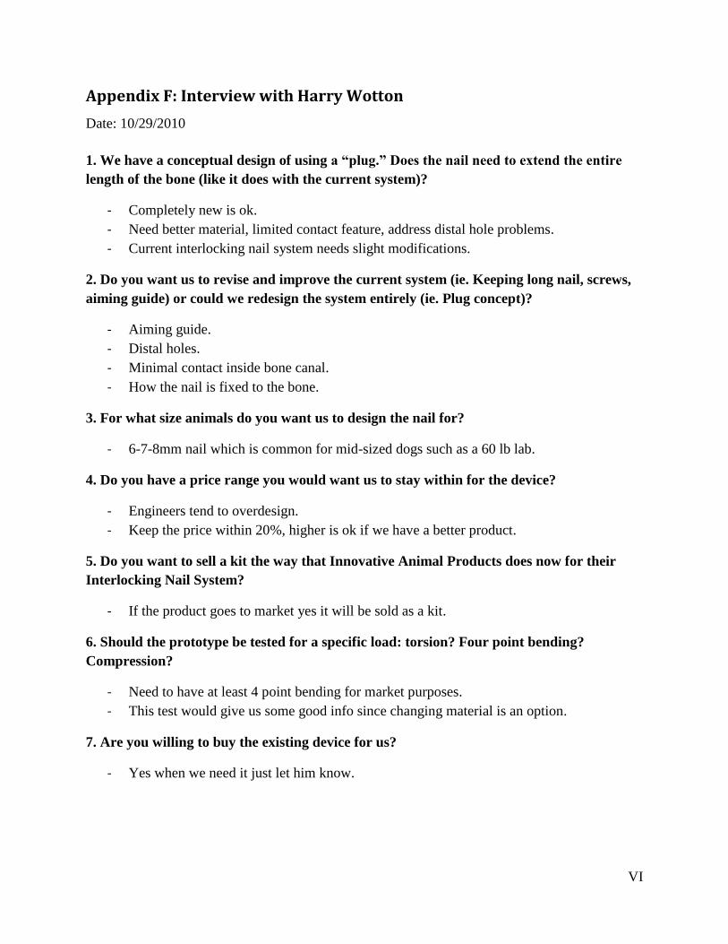
VI
Appendix F: Interview with Harry Wotton
Date: 10/29/2010
1. We have a conceptual design of using a “plug.” Does the nail need to extend the entire
length of the bone (like it does with the current system)?
- Completely new is ok.
- Need better material, limited contact feature, address distal hole problems.
- Current interlocking nail system needs slight modifications.
2. Do you want us to revise and improve the current system (ie. Keeping long nail, screws,
aiming guide) or could we redesign the system entirely (ie. Plug concept)?
- Aiming guide.
- Distal holes.
- Minimal contact inside bone canal.
- How the nail is fixed to the bone.
3. For what size animals do you want us to design the nail for?
- 6-7-8mm nail which is common for mid-sized dogs such as a 60 lb lab.
4. Do you have a price range you would want us to stay within for the device?
- Engineers tend to overdesign.
- Keep the price within 20%, higher is ok if we have a better product.
5. Do you want to sell a kit the way that Innovative Animal Products does now for their
Interlocking Nail System?
- If the product goes to market yes it will be sold as a kit.
6. Should the prototype be tested for a specific load: torsion? Four point bending?
Compression?
- Need to have at least 4 point bending for market purposes.
- This test would give us some good info since changing material is an option.
7. Are you willing to buy the existing device for us?
- Yes when we need it just let him know.