Embed Size (px)
DESCRIPTION
Internal Smart Card Centre Training Series 1
Citation preview

Part 1 Card Technology

Card Era
credit cards have become part of our daily life as forms of plastic money since its first launch in 1960
a magnetic card verse a smart card

Magnetic Card
composed of a layer of magnetic material for storing information
easy to carrycan be use for authenticationwhat is its principles?

Information on Magnetic Card
the stripe is 8.5cm X 1.2cmdata is constructed
based on ISO 7811/2 maximum 3 stripescan store around 1K
bits

ISO Standards
Based on ISO 7811Track 1 is developed by International Air
Transportation Association (IATA) which contains adaptive 6-bit alphanumerical characters
Track 2 is used by American Bankers Association (ABA) which stores 4-bit numerical information containing identification number and control information.
Track 3 is originated by Thrift Industry which contains information which is intended to be updated with each transaction.

TRACK 1
TRACK 2
TRACK 3
IATA ANSI X4.16 — 1983 ISO 3554
ABA ANSI X4.16 — 1983 ISO 3554
THRIFT ANSI X4.16 — 1983 ISO 3554
0.223”
0.110”
0.110”
0.110”
Track 1
SS FC PAN FS NAME FS Additional Data ES LRCPrimary Acc.
No.(19 digits max.)
Name(26 alphanumericcharacters max.)
Exipiry Date 4 Restriction or Type 3 Offset or PVN 5 Discretionary Data
Track 2
FC
SS PAN FS Additional Data ES LRC
Primary Acc.No.
(19 digits max.)
Exipiry Date 4 Restriction or Type 3 Offset or PVN 5 Discretionary Data
SS Start Sentinel % Format Code
FS Field Seperator { ES End Sentinel ? LRC Longitudinal Redundany Code
FCSS Start Sentinel ; Format Code
FS Field Seperator = ES End Sentinel ? LRC Longitudinal Redundany Code
3.250”
FC
Magnetic stripe Content of Financial Cards

Capacity
Track Record density bits/inch Capacity
1 210 79 (7 bits/char.)2 75 40 (5 bits/char.)
3 210 107 (5 bits/char)

Fraud card activities Stealing — A legal card may be stolen and used in
ATMs or EPOSs. Altering and re-embossing a genuine card, that is
modifying the visual features of card. Skimming or altering the original electronic data
stored on the magnetic stripe, for example the expire date or the credit limit.
Buffering or re-encoding the original data to the magnetic card. This technique is commonly used in producing card counterfeits of store-value ticket.

Copying of data from a genuine card to another in an on-line fashion “white plastic fraud”
Counterfeiting — “color plastic fraud” may be prepared by reading another legal card and encoding the same information onto another fraud card in an off-line fashion.

Valid Card
Fraud Card

Design of card protection technologies
Validation by Appearance — this is a visual mean to protect against illegal duplication of plastic card. The aim is to make the appearance of card so unique and difficult to duplicate that shopkeepers or card handlers can identify the genuine card instantly.
Verification on Access — this validation relies on the interaction with the card holder, the objective of the protection mechanism is to identify the person accessing the card is an authorized one.

Protection on Data — this is a machine readable protection to avoid data from being access and duplication illegally. The importance of stripe data protection is .to ensure the security of electronic transaction and provide an alternative verification mechanism of magnetic card.

Magnetic StripeProtection
Card Protection Technologies
Visual ProtectionTechnologies
Protection onAccess
Verification byCard Content
Protection onModification
Protection onDuplication
Holograms
Microprints
UltravioletPattern
Photocard
Signature
DNA
PIN
PVV
EmbossedInformation
CVC
Smart Card
Memory Card P Card
WatermarkSandwichMagneprintValugard
Xsec
Holomagnetic
Xshield
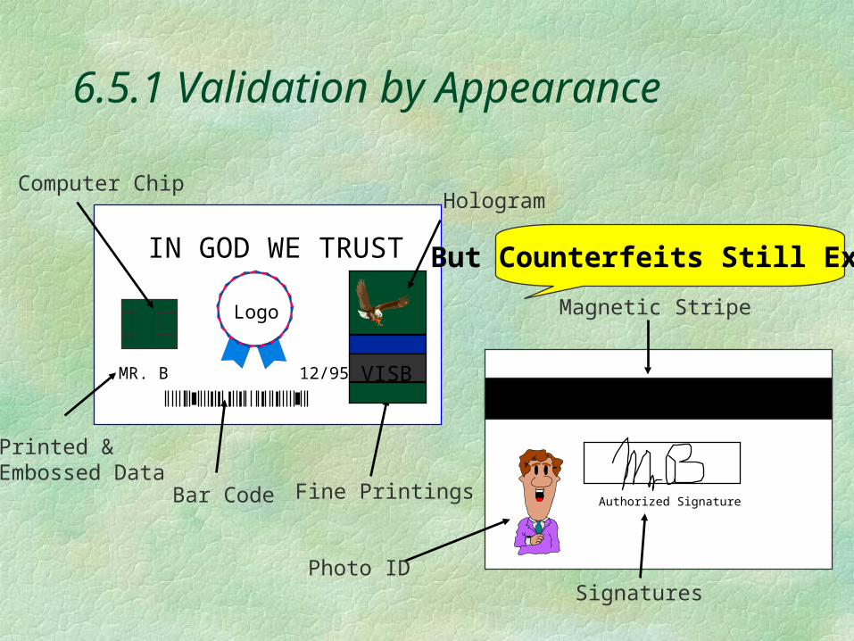
6.5.1 Validation by Appearance
MR. B 12/95 VISB
IN GOD WE TRUST
Authorized Signature
Logo
Hologram
Magnetic Stripe
Bar Code
Computer Chip
Printed &Embossed Data
Signatures
Fine Printings
Photo ID
But Counterfeits Still Exists!
Holograms
are the most notable marking for credit cardsproduced by a combination of photography
and laser beamsinitially counterfeit holograms were crude
and manufactured by stamping tin foilsrecently counterfeit holograms were
produced by professional technical knowledge is needed to validate the authenticity of holograms

Embossed characters
are some raised marks implemented on the plastic surface of card
the embossed information includes the user name, expiry date, card number and unique embossed symbol — VISA embossed a symbol like “CV” besides the expiry date.
However, the card material is a thermal plastic by warming the card to about 50C, it allows “debossing” of the characters and re-embossing with fraud information.

Photocardsare introduced by CitiBank Corporation the effectiveness of photocard on marketing
purposes seems to be greater than that on security
it is not an effective mean to stop card fraud because counterfeiters had the ability to imitate laser engraved photographs and signatures in rather low cost using a photomachine of around US$ 5000.

Ultra-violet dove, bank identifying number (BIN) and micro-printings
can also be duplicated under the existing technologytechnical knowledge is needed to recognize a
counterfeit card from a genuine onemost card reading terminals contain no visual
detector to validate these visual protection features while human eyes are not a reliable mean of verification
difficult to validate a genuine card

Protection on Card Access
the card holder is requested to prove his identity or the authorized user will be acknowledged about the transaction
methods: signature biometrices PIN

Signature
Signature is the most popular way of verification.
When a transaction is made, the card holder is requested to sign and the signature will be verified visually.
this method is simple not useful in protection against “color plastic
fraud” where the criminal can sign their own signature in the fraud card.

Biometrics
biometrics features were developed such as speed of writing, fingerprint or iris pattern
implementation cost is hightheir accuracy is questionable

Personal identifying number (PIN)
PIN is a unique number given by the bank to each user which is effectively fixed by the customer account number and the cryptographic key used in the derived PIN computation.
PIN offset or password is a value that relates a derived PIN to actual PIN value.

When a card holder transfer or withdraw his money from a bank account, a 6-digits password is inputted before transaction processed.
The password will be validated by comparing with the one stored inside the magnetic card by offset or in a centralized database in the bank.

The security of password is relied on the encryption algorithm of PIN, the PIN management scheme and the secrecy of password.
PIN does not provides defense against data copied from another card which contains the correct card verification value.
Moreover, the encryption algorithm adopted in validation codes may be tampered and decoded by professional hackers with some insider information.

Protection on Data
the major magnetic card protection techniques have included Watermark Magnetic Print Valugard Xsec-Jitter Macaps

Smart Card
Integrated Circuit - chip
originated from France
invented in 70 and matured in 90
Magnetic Card replacement

Types of Smart Card
Memory CardMPU IC cardCrypto- processor cardContactless card

Memory CardMemory Card
Primitive typecomposed of
EEPROM/PROMsimple functionas prepay card

Cypto-processor IC CardsCypto-processor IC Cards
composed of cypto-processor & PROM
a powerful MPUcan recognise
illegal signal and security features

MPU IC Smart CardMPU IC Smart Card
Composed of MCU/MPC
software drivenhave flexibility and
primitive intelligence
some security features

Contactless Smart CardContactless Smart Card
similar to contact smart card
with RF transceiver to increase robustness and security

Advantages of Smart Card
Large storage capacitymore security featuresmultiple functionsflexibility in use - intelligent, lower power
consumption, effective packagingas access card, electronic purse, debit/credit
cards, ID card etc. - particular off-line applications

Hardware Technologies
new memory technologies - EEPROM and flash-EPROM
new silicon technologies - 1.3 m to 0.65 or even 0.18m for more storage and security, lower power consumption
new packaging technologies - against breakage, rubbing and bending

Smart Card Software
Intelligent Chip Operating System -COSEncryption techniques - RSA & DESMultiple Application OS (MAOS)
Mondex, EMV, GSM, LoyaltyNew requirements
hot list, trust key management

6.6.4 Smart Card Worldwide
Use Distribution 40% Western Europe, 25% Asia, 15% North America, 8% South America and 12% others
Major user is France over 130M cardsGermany 80 M health insuranceover 20 countries use GSM and electronic
purse

Smart Card Project Worldwide
Mondex - UKBarclay/Mercury one-2-one project (UK)Detemobil Toll Collection (UK)Advantages Card in RSAID card in TaiwanMastercard &Visa + Netscape and Microsoft -
COS projectCredit Card in USA

Some Difficulties Worldwide
Bank card project cancellation - TaiwanMondex tampering slow down bank sector
development - RSA and New ZealandMastercard - year 2000 delay of massive
launchingVisa - adoption of magnetic card in RSA debit
card project Major concern - COST EFFECTIVENESS
Smart Card in Hong Kong
MondexVisa CashCity SmartOctopus - smart travelling cardJockey Club -pre-pay cardNew airport - access control cardHKT - telephone cardParking Meter - prepay card project

Smart Card in Electronic Commerce
Electronic Data Interchange (EDI)TradelinkElectronic PurchasingHome BankingInternet Shopping

New Technologies Required
Data Storage Management - information protection
authentication process - biometric: fingerprint, facial features, iris
identification, dynamic signature recognition, speech recognition
encryption methods - Elliptic Curve Cryptography, chaotic techniques

THE SMART CARD MARKET IN THE YEAR 2000 (in millions – Source: Philips Communication Systems)
Application France Europe Others TotalPhone cards 140.8 553.1 640.0 1334GSM cards 4.0 15.0 42.0 61Health cards 10.0 55.0 92.0 157Bank cards 25.0 85.0 75.0 185ID cards - - - -Transport tickets - - - -Pay TV cards 4.5 24.0 81.0 110Access control 1.8 3.0 5.0 10City cards /Misc 24.0 55.1 64.3 143Total 210.1 790.2 999.3 2000

Some Difficulties Worldwide
Bank card project cancellation - TaiwanCard tampering slow down bank sector
development - RSA and New ZealandMasterCard - year 2000 delay of massive
launchingVisa - adoption of magnetic card in RSA
debit card project Major concern - COST EFFECTIVENESS

Smart Card in Electronic CommerceElectronic Data Interchange (EDI)TradelinkElectronic PurchasingHome BankingInternet Shopping

New Technologies Required
Data Storage Management - information protection
authentication process - biometric: fingerprint, facial features, iris identification,
dynamic signature recognition, speech recognitionencryption methods -
Elliptic Curve Cryptography, chaotic techniques

Smart Card in Mobile Phone Applications Wireless Application Protocol (WAP) emerges for
a mobile Internet accessResearch work launched in Japan indicates a good
market if available.Mobile operators will provide add on WAP
gateways and WAP services to enable wireless internet services:
Banks, financial institutions, restaurants, retailers, Utilities, transit operators, hotels, entertainment and media, selling goods and information

Limitation, the SIM card inside the WAP phone cannot provide complicated the PKI authentication process thus security is an issue.
A possible solution is to introduce an additional smart card interface (either contact or contactless) to enable the authentication process. (MasterCard – dual card phone)

New technologies requirements: The development of m-PKI (mobile PKI) in the
multiple-application OS is more essential and practical
The development of high security low power card modules
A better interface to new wireless internet platform, other ancillary technologies, such as Bluetooth and Wireless Wallets are also important

Java Card
More powerful processor & memoriesAllow download of applicationsOpen software platform for code
transportabilityFor multi-function, e-purse, loyalty, health
care database and Internet/Intranet access card

Smart Card in Hong KongMondexVisa CashCampus cardOctopus - smart traveling card Jockey Club -pre-pay cardNew airport - access control cardTelephone card & SIM CardParking Meter - prepay card projectResidential access cardPossible new ID card, Road Toll Pay Card

Governing Body
The Hong Kong Monetary Authority will set rules on use of smart card for financial applications
only banks may issue general purpose cardsHKMA can authorize other non-bank issuer
core use relating to business of the issuer needs to establish a business case an non-core uses non-core uses subject to limits determined by
HKMA

Exemptions
Risk to payment system and card holders is slight
replace an existing non-regulated payment instrument like travelers’ cheques
soundness of issuermax. of HK$1000 limits on cardonly allow 15% for non core usesuse in a limited and distinct areas

Examples
Mondex : equivalent to bank note, and no audit trail
Visa Cash: equivalent to cheques, link to accounts and have audit trails

Note : There is no clearing system for the transfer to Mondex value (in the same way as transfer of bank notes).
Notes IssuingBank
Other Banks
Notes holder A
Notes holder B MerchantBank notesGoods/Services
Adjustment tointerbank A/C Bank notes
Adjustment tocustomer A/C Bank notes
Transf
er of
bank
notes
Goods/Services
Bank notes
MondexOriginator
Member Banks
Cardholder A
Cardholder B MerchantMondex valueGoods/Services
Adjustment tointerbank A/C Mondex value
Adjustment tocustomer A/C Mondex value
Transf
er of
Monde
x
value
Goods/Services
Mondex value
Issue of Bank Notes Origination of Mondex Value
Mondex scheme

Cheques VisaCash
Note : Transfer of VisaCash value would go through a clearing system in same way as clearing for cheques.
Payment by cheque
Issue ofcheques
Presentation of cheque received from customer
Credit Merchant A/C Goods/ Services
Payment by card
Uploadingvalue onto card
Redemption of value received from cardholder
Credit Merchant A/C
Debit Customer A/C (after cheque is cleared)
Debit Customer A/C(once value is uploaded)
Goods/ Services
Bank
ChequeClearingSystem
Merchant
BankCustomer
VisaCashClearingSystem
Bank
Merchant
Cardholder
VisaCash scheme

ISO 7816 Standards
7816/1• Specifies the physical and dimensional
features of the plastic supports. Additional characteristics specified are Mechanical strength, Static electricity, Electromagnetic fields and Bending properties etc.
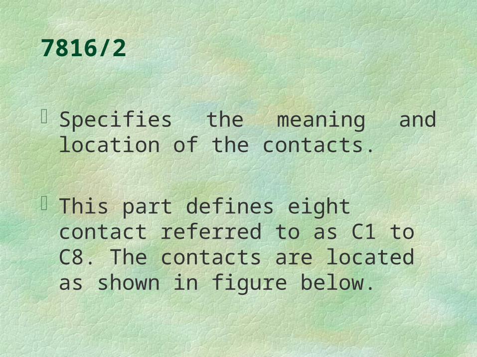
7816/2
Specifies the meaning and location of the contacts.
This part defines eight contact referred to as C1 to C8. The contacts are located as shown in figure below.


Pin Assignment
Cont
act
No.
Assignment Contact
No.
Assignment
C1 VCC (supply voltage) C5 GND (ground)
C2 RST (reset signal) C6 VPP (Programming
voltage)
C3 CLK (clock signal) C7 I/O (Data input/output
C4 Reserved to ISO/IEC JTC
1/SC 17 for future use
C8 Reserved to ISO/IEC
JTC 1/SC 17 for future
use

7816/3Specifies electronics signals and
transmission protocols that the DC electrical characteristics, the character format and the command protocol for the Smart Card.
This ISO standard describes two types of data transfer between Smart Card and card Reader/Writer: asynchronous protocol with two data coding
conventions synchronous protocol

Asynchronous protocol
Character format:Each character (described in figure below)
is composed of: one start bit 8 bits of data one even parity bit guardtime slot including two stop bits

The data speed transmission depends on the clock signal frequency input into the Smart Card on the CLK contact.
The nominal bit duration sent on the I/O line is called the "elementary time unit" "etu" by the ISO standard.

This bit duration is directly proportional to the input clock during the "answer to reset", but may be requested to be modified (by the Smart Card) for the following data exchange. The parameters of this modification are given during the "answer to reset".


I/O Line management:
The I/O line (Input/output line) is used to exchange data in input mode (reception mode) or in output mode (transmission mode). This line must have two states: stand-by state or high level state working state or low level state:

Furthermore, the I/O line (as shown in figure below) is used to generate or to detect data parity errors in reception or transmission The transmitter must sample the I/O line during the guardtime duration. The transmission is presumed valid if the I/O line stays
at a high level during the guardtime slot The transmission is wrong if the I/O line is pulled
down during at least one etu (two etu max) during the guardtime slot.
The receiver, in order to signal a reception error, must pull down the I/O line.

Data coding
The ISO 7816 - 3 standard gives the possibility of two kinds of data coding. The direct convention or inverse convention. The type of convention is fixed by the Smart Card and is declared in the first character of the "answer to reset'.

In direct convention, the logical "l " level is 5 Volt and the least significant bit (LSB) is transmitted first.
In inverse convention, the logical "1" level is 0 Volt and the most significant bit (MSB) is transmitted first.

Synchronous protocol
In synchronous protocol, successions of bits are sent on the I/O line, synchronized with the clock signal on CLK pin. In synchronous protocol, the data frame format described previously is not available.

7816/4Specifies the inter-industry command for
interchange include:The content of the message, commands and
responses, transmitted by the interface device to the card and conversely.
The structure and content of the historical bytes sent by the card during the answer to reset.

The structure of files and data, as seen at the interface when processing inter-industry commands for interchange.
Access methods to files and data in the card.A security architecture defining access rights
to files and data in the card.Methods for secure messaging.

APDU (application protocol data unit) message structure
A step in an application protocol consists of sending a command, processing it in the receiving entity and sending back the response. Therefore a specific response corresponds to a specific command, referred to as a command-response pair.
An application protocol data unit (APDU) contains either a command message or a response message, sent from the interface device to the card or conversely.
In a command-response pair, the command message and the response message may contain data, thus inducing four cases, which are summarized by table below.
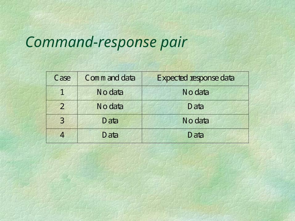
Command-response pair
Case Command data Expected response data
1 No data No data
2 No data Data
3 Data No data
4 Data Data

Command APDU structure
Header Body
CLA INS P1 P2 (Lc field) (Data field) (Le field)
CLA - Class byteINS - Instruction byteP1, P2 - Parameter byteLc field - number of bytes present in the data fieldLe field - maximum number of bytes expected in the data field of the response APDU


Response APDU structure
The response APDU consists of Conditional body of variable length. Mandatory trailer of 2 byte.
Body Trailer
Data field SW1 SW2

Status Codes of response APDU trailer.

Part 2 Card Security

Simple security
Random Number Generator for dynamic key generation
Cipher Engine for data protection: Block Stream Choatic Function

Random Number Generator
For generation of session keysDigital approach can only generate pseudo
random number based on Xi =(a Xi-1 + b) mod c
Other use analogue approaches like VCO, white noise generator etc.

Block CipherK1: Master Key of
length 16-bitK2: Card ID of
length 16-bit
Block Cipher8-bit
K1 : 16-bit K2 : 16-bit
DataIn DataOut8-bit
Block Cipher8-bit
K1 : 16-bit K2 : 16-bit
DataOut DataIn8-bit
Block Cipher Method – Write to Memory
Block Cipher Method – Read from Memory

K1 and K2 act as the key parameters to the block cipher
The block cipher constructs a one-to-one mapping For different combination of K1 and K2, different
mapping can be obtainedExhaustive search through 28=256 combinations,
the mapping can be obtained without revealing the key parameters
To reveal the key parameters, exhaustive search of 2^16*2^16=2^32 combination is required
If the Card ID is known, a search of 2^16 combinations can reveal the Master Key

Stream Cipher The Stream Cipher can be
viewed as a state machine with K1K2 as the initial state
It generates a pseudorandom number sequences which are XOR with the Input Data to form the Output Data
The data must be in sequence in order to encode and decode correctly
Not suitable
Stream Cipher
K1 : 16-bit
DataOut8-bit8-bit
DataIn
K2 : 16-bit

Chaotic Function
8-bit
8-bitNN
8-bitNN
8-bitNN
8-bitNN
8-bit
K1 : 16-bit
8-bit 8-bit
K2 : 16-bit
2-bit 2-bit 2-bit 2-bit
Neural Network
DataOut8-bit8-bit
DataIn
8-bit
K2 : 16-bitK1 : 16-bit

The neural network construct a mapping for 32-bit input and 8-bit output
The 8-bit output for the Neural Network is XORed with the Input Data to from the Output Data
For different K1 & K2, the same output of Neural Network will be obtained, collision occurs
Knowing a pair of Data input and Data Output will recover the output from the Neural Network
As collision occurs, knowing K1, exhaustive search through K2, different K2 will result the same output, hence increase difficulty in searching K2
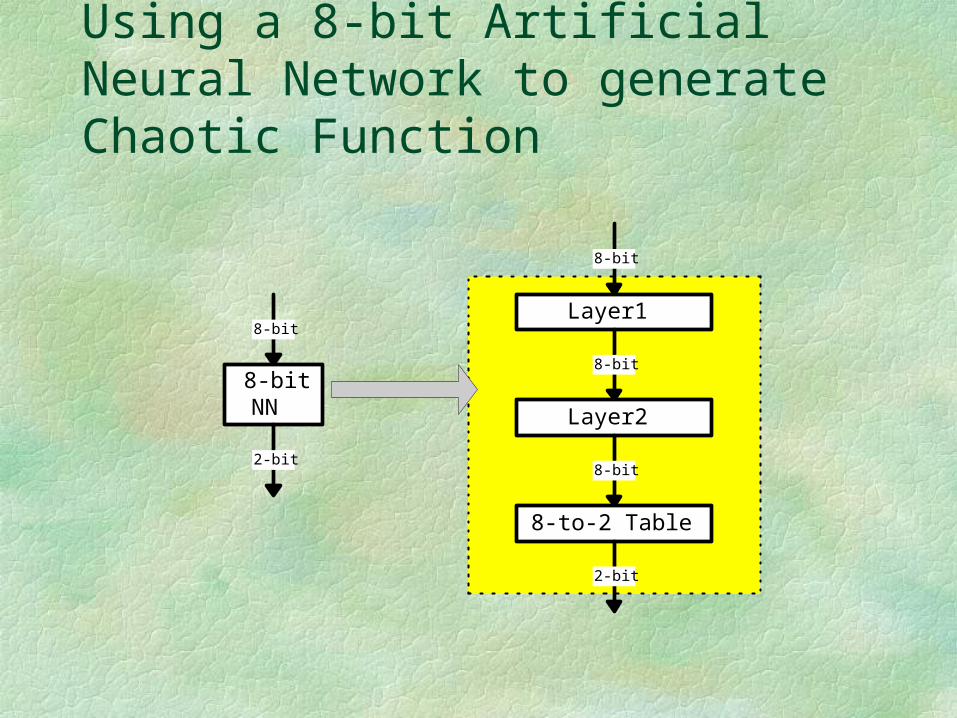
Using a 8-bit Artificial Neural Network to generate Chaotic Function
8-bit
8-bitNN
2-bit
8-bit
Layer1
8-bit
Layer2
8-bit
8-to-2 Table
2-bit

Advance Data Protection - EncryptionEncryption
Encryption will modify data into irregular form for security storage and transmission. The reconstruction is achieved by using a set of relevant Keys.
Two cryptosystems are currently being used, i.e. symmetric (DES/FEAL) and asymmetric (RSA, ECC). Symmetric cryptosystem requires only one common key for encryption and decryption whereas asymmetric system requires two keys, i.e. private/user key and public/system key.
Common Encryption Techniques
Three algorithms will be introduced DES (Data Encryption Standard) RSA (Rivet, Shamir, Adleman) ECC (Elliptic Curve Cryptography)

DESDES
the most well-known symmetric system being used by banking sector and computer security.
the technique was originated from IBM and certified by National Bureau of Standards in 1977.
an official unclassified data encryption method.
widely been used by Banking sectors

64 Bit Plaintext
Initial Permutation
32 Bit L0 32 Bit R0
F(R0,K1)+
32 Bit L1 32 Bit R1
32 Bit L15 32 Bit R15
F(R15,K16)+
32 Bit L16 32 Bit R16
Final Permutation
64 Bit Ciphertext
Encryption Process DES System64 Bit Key
Permutation Choice 1
56 Bit Key
28 Bit C0 28 Bit D0
Left Shift Right Shift
C1 D1
BuildingBlock
PermutedChoice 2
K1(48 bits)
C16 D16
PermutedChoice 2
Key Schedule


Li-1
32 bitsRi-1 32 bits
ExpansionPermutation 48 bits
S-BoxSubstitution
choice 32 bits
P-box Permutation
Li
32 bitsRi
32 bits
56 bits KeyPermuted Choice
48 bits
Function f

DES Substitution Boxes Operation


Operation Tables of DES (IP, IP-1, E and P)

RSARSA
developed by 3 researchers at MIT in 1977 based on two prime numbers (p & q) to generate
the keys most popular is RSA 129 where p x q gives a
129 bit number highly security and has once been proposed to
replace DES in banking application report cipheranalysed by a group of 600
specialist in May 1994 through internet

RSA StepsSelect two large prime p& qGenerate n = pqGenerate f(n) = (p-1)(q-1)Select e (encryption/public key) and d
(decryption/secret) as ed = 1 (mod(f(n))
Encrption by C =(Me, mod n) where M is the message
Decrypt by M =(Cd, mod n)

ECC
ECC a new elliptic curve cryptosystem method for
public key applications developed by Neil Koblitz (Washington
University) and Victor Miller (IBM, Yorktown Heights) in 1985
using points in the elliptic curve as the elements for encryption
will become IEEE standard in 1997/8 (99?)

Elliptic Curve Groups over Real Numbers An elliptic curve over real numbers may be
defined as the set of points (x,y) which satisfy an elliptic curve equation of the form:
y2 = x3 + ax + b, where x, y, a and b are real numbers.
Each choice of the numbers a and b yields a different elliptic curve.

For example, a = -4 and b = 0.67 gives the elliptic curve with equation y2 = x3 - 4x + 0.67; the graph of this curve is shown below:
If x3 + ax + b contains no repeated factors, or equivalently if 4a3 + 27b2 is not 0, then the elliptic curve y2 = x3 + ax + b
Can be used to form a group. An elliptic curve group over real numbers consists of the points on the corresponding elliptic curve, together with a special point O called the point at infinity.
P + Q = R is the additive property defined geometrically.

Elliptic Curve Addition: A Geometric Approach Elliptic curve groups are additive groups; that is,
their basic function is addition. The addition of two points in an elliptic curve is defined geometrically.
The negative of a point P = (xP,yP) is its reflection in the x-axis: the point -P is (xP,-yP). Notice that for each point P on an elliptic curve, the point -P is also on the curve.
Adding distinct points P and Q Suppose that P and Q are two distinct points
on an elliptic curve, and the P is not -Q. To add the points P and Q, a line is drawn through the two points. This line will intersect the elliptic curve in exactly one more point, call -R. The point -R is reflected in the x-axis to the point R. The law for addition in an elliptic curve group is P + Q = R. For example:


Adding the points P and -PThe line through P and -P is a vertical line which does
not intersect the elliptic curve at a third point; thus the points P and -P cannot be added as previously.
It is for this reason that the elliptic curve group includes the point at infinity O.
By definition, P + (-P) = O. As a result of this equation, P + O = P in the elliptic curve group . O is called the additive identity of the elliptic curve group; all elliptic curves have an additive identity.


Doubling the point PTo add a point P to itself, a tangent line to the
curve is drawn at the point P. If yP is not 0, then the tangent line intersects the elliptic curve at exactly one other point, -R. -R is reflected in the x-axis to R. This operation is called doubling the point P; the law for doubling a point on an elliptic curve group is defined by:
P + P = 2P = R. The tangent from P is always vertical if
yP = 0.


Doubling the point P if yP = 0
If a point P is such that yP = 0, then the tangent line to the elliptic curve at P is vertical and does not intersect the elliptic curve at any other point.
By definition, 2P = O for such a point P.
If one wanted to find 3P in this situation, one can add 2P + P. This becomes P + O = P Thus 3P = P.
3P = P, 4P = O, 5P = P, 6P = O, 7P = P, etc.


Elliptic Curve Addition: An Algebraic Approach Geometrical approach is not practical
Adding distinct points P and Q When P = (xP,yP) and Q = (xQ,yQ) are not negative of
each other,P + Q = R where
s = (yP - yQ) / (xP - xQ)xR = s2 - xP - xQ and yR = -yP + s(xP - xR)
Note that s is the slope of the line through P and Q

Doubling the point P
When yP is not 0,
2P = R where
s = (3xP2 + a) / (2yP )
xR = s2 - 2xP and yR = -yP + s(xP - xR)
Recall that a is one of the parameters chosen with the elliptic curve and that s is the tangent on the point P.

Elliptic Curve Groups over FpCalculations over the real numbers are slow and inaccurate
due to round-off error. Cryptographic applications require fast and precise arithmetic; thus elliptic curve groups over the finite fields of Fp and F2m are used in practice.
Recall that the field Fp uses the numbers from 0 to p - 1, and computations end by taking the remainder on division by p. For example, in F23 the field is composed of integers from 0 to 22, and any operation within this field will result in an integer also between 0 and 22.

An elliptic curve with the underlying field of Fp can formed by choosing the variables a and b within the field of Fp. The elliptic curve includes all points (x,y) which satisfy the elliptic curve equation modulo p (where x and y are numbers in Fp).For example: y2 mod p = x3 + ax + b mod p has an underlying field of Fp if a and b are in Fp.
If x3 + ax + b contains no repeating factors (or, equivalently, if 4a3 + 27b2 mod p is not 0), then the elliptic curve can be used to form a group. An elliptic curve group over Fp consists of the points on the corresponding elliptic curve, together with a special point O called the point at infinity. There are finitely many points on such an elliptic curve.

Example of an Elliptic Curve Group over Fp As a very small example, consider an elliptic curve over the
field F23. With a = 1 and b = 0, the elliptic curve equation is y2 = x3 + x. The point (9,5) satisfies this equation since:
y2 mod p = x3 + x mod p
52 mod 23 = 93 + 9 mod 23
25 mod 23 = 738 mod 23
2 = 2
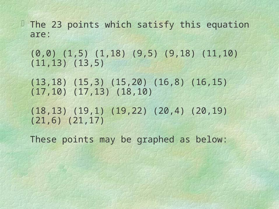
The 23 points which satisfy this equation are:
(0,0) (1,5) (1,18) (9,5) (9,18) (11,10) (11,13) (13,5)
(13,18) (15,3) (15,20) (16,8) (16,15) (17,10) (17,13) (18,10)
(18,13) (19,1) (19,22) (20,4) (20,19) (21,6) (21,17)
These points may be graphed as below:


Arithmetic in an Elliptic Curve Group over Fp There are several major differences between elliptic
curve groups over Fp and over real numbers. Elliptic curve groups over Fp have a finite number of
points, which is a desirable property for cryptographic purposes. Since these curves consist of a few discrete points, it is not clear how to "connect the dots" to make their graph look like a curve. It is not clear how geometric relationships can be applied.

As a result, the geometry used in elliptic curve groups over real numbers cannot be used for elliptic curve groups over Fp. However, the algebraic rules for the arithmetic can be adapted for elliptic curves over Fp. Unlike elliptic curves over real numbers, computations over the field of Fp involve no round off error - an essential property required for a cryptosystem.
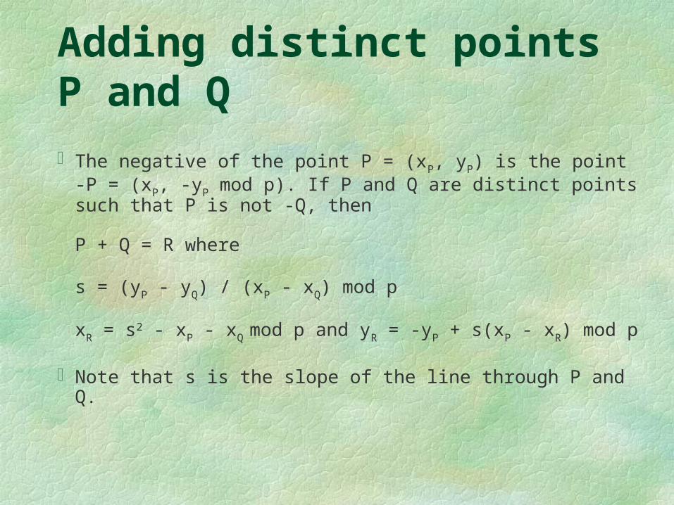
Adding distinct points P and Q The negative of the point P = (xP, yP) is the point -P = (xP, -yP
mod p). If P and Q are distinct points such that P is not -Q, then
P + Q = R where
s = (yP - yQ) / (xP - xQ) mod p
xR = s2 - xP - xQ mod p and yR = -yP + s(xP - xR) mod p
Note that s is the slope of the line through P and Q.

Doubling the point P Provided that yP is not 0,
2P = R where
s = (3xP2 + a) / (2yP ) mod p
xR = s2 - 2xP mod p and yR = -yP + s(xP - xR) mod p
Recall that a is one of the parameters chosen with the elliptic curve and that s is the slope of the line through P and Q.

Elliptic Curve groups and the Discrete Logarithm Problem At the foundation of every cryptosystem is a hard
mathematical problem that is computationally infeasible to solve. The discrete logarithm problem is the basis for the security of many cryptosystems including the Elliptic Curve Cryptosystem. More specifically, the ECC relies upon the difficulty of the Elliptic Curve Discrete Logarithm Problem (ECDLP).

Recall that we examined two geometrically defined operations over certain elliptic curve groups. These two operations were point addition and point doubling. By selecting a point in a elliptic curve group, one can double it to obtain the point 2P. After that, one can add the point P to the point 2P to obtain the point 3P. The determination of a point nP in this manner is referred to as Scalar Multiplication of a point. The ECDLP is based upon the intractability of scalar multiplication products

The Elliptic Curve Discrete Logarithm Problem In the multiplicative group Zp*, the discrete logarithm problem
is: given elements r and q of the group, and a prime p, find a number k such that r = qk mod p. If the elliptic curve groups is described using multiplicative notation, then the elliptic curve discrete logarithm problem is: given points P and Q in the group, find a number that Pk = Q; k is called the discrete logarithm of Q to the base P. When the elliptic curve group is described using additive notation, the elliptic curve discrete logarithm problem is: given points P and Q in the group, find a number k such that Pk = Q

Example:
In the elliptic curve group defined by
y2 = x3 + 9x + 17 over F23,
What is the discrete logarithm k of Q = (4,5) to the base P = (16,5)?

One way to find k is to compute multiples of P until Q is found. The first few multiples of P are:
P = (16,5) 2P = (20,20) 3P = (14,14) 4P = (19,20) 5P = (13,10) 6P = (7,3) 7P = (8,7) 8P = (12,17) 9P = (4,5)
Since 9P = (4,5) = Q, the discrete logarithm of Q to the base P is k = 9.
In a real application, k would be large enough such that it would be infeasible to determine k in this manner.

ECC - key generationSelect an elliptic curveGenerate the coordinate pairs which satisfy the
conditions of modulo n and select starting point PKey generation:
select a random integer d (secret key) in the interval [2, n-2]
compute point Q = dP make Q public

ECC Encryption
Encryption select a random integer k in the interval [2, n-2] compute (x1,y1) = kP and (x2,y2) = kQ generate a mask Y from secret as f(x2) and
compute C = YM where M is the message send the encrypted ciphertext EM as
concatenated [x1, y1, C]

ECC Decryption
Decryption extract (x1,y1) from ciphertext EM compute (x2,y2) from d(x1,y1) compute mask Y as f(x2) recover message by M = CY

Encryption and Decryption :
Actions perform by Party B
Encryption :
Actions perform by Party A
Decryption Process
1. Looks up A public key : Q =
(xQ,yQ)
= ( ,0)
2. Select a random integer k = 2 in the
interval [2, n -2 ] - the private key
for
the one - time key pair
3. Computes the point (x1,y1) = kP =
2(5, 11) = ( , ) = ((1100),(1100))
- the public key for one - time key
pair
4. Computes the point (x2,y2) = kQ =
2( , ) = (5, 11) = ((1010),(1110))
x2 is the secret value.
5. Generates a mask Y of length 6
with the mask generation function
used, Y will vary. For the purposes
in this example, let Y = 011010.
6. Computes C = Y M = (011010) (010100) = (001110)
7. Computes the encrypted message
by concatenating (x1,y1) and C,
and transmit (11001100001110) to
A.
1.Ciphertext EM = (11001100001110)
received from B
2. Uses the first 8 bits of the string for
one
- time public key : ((1100),(1100)).
The rest of EM will be stored in C
3. Computes the point (x2,y2) = d
( x1,y1) = 3 (1100,1100) = 3(, ) =
(5, 11)= ( (1010),(1110)). X2 is the
secret value.
4. Using the same mask generation
function as B, A generate from x2 the
mask Y = 011010.
5. Recover the message M by XORing
all
but the first 8 bits of EM with the
mask Y: M : C Y = (001110)
(011010) = (010100)

Security of Smart Card
Possible attacks tracking: based on the protocol exchange between
the terminal and the card to track the sequence of commands
EM analysis: use electron microscope to inspect the internal structure of the mask
confusion: disturb the power supply during PIN verification to confuse the accurate enter of PIN and allow access to the protected memory

UV or X-ray inspection: use high efficiency UV or X-ray to inspect the memory areas to extract important information like PIN, secret key and public key
Other possible attracts: attract on DES like differentiate methodsattract on RSA using cyclic properties

Trusted System Evaluation Criteria – USA(DoD)D: Minimal protection
No protectionC1: Discretionary Security Protection
Use control acessC2: Controlled Access Protection
Use accountability/auditingB1: Labelled Security Protection
Use sensitivity (classification) labels

B2: Structured Protection Use formal security policy more resistant to
penetrateB3: Security domain
Highly resistant to penetration. Use security administrator, auditing events and system recovery process
A1: Verified protection Highly assure of penetration. Use formal
specification and verification approaches.

Information Technology Security Evaluation Criteria (ITSEC) - Europe
EAL1 – functional testedEAL2 – structurally testedEAL3 – methodologically tested and checkedEAL4 - methodologically designed, tested and
reviewedEAL5 – semiformally designed and tested EAL6 - semiformally verified designed and tested EAL7 -formally verified designed and tested

Security requirementsCryptographic modulesmodule interfacerole and servicesfinite state machine modelphysical securityEnvironmental Failure Protection/Testing
(EFT/EFP)Software security

Operation securitycryptographic key managementcryptographic algorithmEMI/EMCself tests

Security Assessment
USA Federal Information Processing Standard Publications 140-2 (FIPS PUB 1401-2): Specifications for security requirements for cryptographic modules
The specifications define 4 levels security: SL 1 to SL 4 where SL 1 is the lowest

Type SL1 SL2 SL3 SL4
1 CryptographicModules
Define interfacing, H/W, S/W, Firmware & Module SecurityPolicy
2 ModuleInterface
Define require and backupinterface, define path formatfor interface and internalcircuit
Dta port is an important issueand must be isolate fromother information links
3 Role andservices
Logicseparate therole andservices
Must applyrole basedauthentication
Apply Identity basedauthentication
4 Finite statemachine model
Define model, state and state transitional diagram and thestate transitional conditions
5 Physicalsecurity
Manufacturerclassificationlayers
Provide lockandmodificationevidents
Detection ofillegalmodificationsand responsefor coversand doors
Detection ofillegalmodificationsand responseenvelope foraccess
6 EFP/EFT Not required Temperature and voltage

7 S/w security S/W must be tested byfinite state machine model
H/L language Formal model
8 O/S Security Executecode,authentication and accesscontrol forsinglemachine/user
Read/writeprotection inC2 level
Indicateprotection in B1level with areliablecommunicationpath
Structural protection in B2level
9 Cryptographic Keymanagement
Use FIPS endorsed creationand distribution methods
Use encryption or split knowledge methods toinput/output keys
10 Cryptographic algorithms
Use FIPS endorsed non-classified document encryption algorithms
11 EMI/EMC FCC Part 15 J class A orequivalent
FCC Part 15 J class B or equivalent
12 Self test Provide power up tests and conditional tests

*** END ***