Embed Size (px)
Citation preview
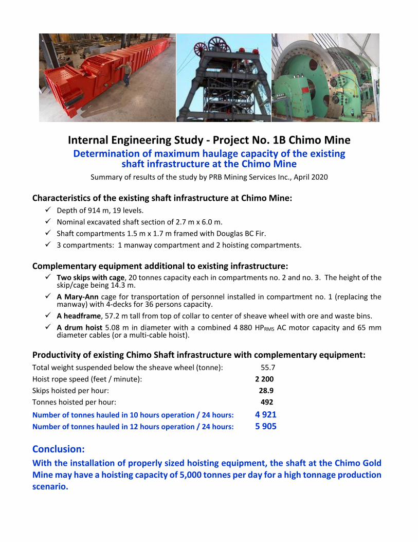
Internal Engineering Study - Project No. 1B Chimo Mine
Determination of maximum haulage capacity of the existing shaft infrastructure at the Chimo Mine
Summary of results of the study by PRB Mining Services Inc., April 2020
Characteristics of the existing shaft infrastructure at Chimo Mine:
✓ Depth of 914 m, 19 levels.
✓ Nominal excavated shaft section of 2.7 m x 6.0 m.
✓ Shaft compartments 1.5 m x 1.7 m framed with Douglas BC Fir.
✓ 3 compartments: 1 manway compartment and 2 hoisting compartments.
Complementary equipment additional to existing infrastructure:
✓ Two skips with cage, 20 tonnes capacity each in compartments no. 2 and no. 3. The height of the skip/cage being 14.3 m.
✓ A Mary-Ann cage for transportation of personnel installed in compartment no. 1 (replacing the manway) with 4-decks for 36 persons capacity.
✓ A headframe, 57.2 m tall from top of collar to center of sheave wheel with ore and waste bins.
✓ A drum hoist 5.08 m in diameter with a combined 4 880 HPRMS AC motor capacity and 65 mm diameter cables (or a multi-cable hoist).
Productivity of existing Chimo Shaft infrastructure with complementary equipment:
Total weight suspended below the sheave wheel (tonne): 55.7
Hoist rope speed (feet / minute): 2 200
Skips hoisted per hour: 28.9
Tonnes hoisted per hour: 492
Number of tonnes hauled in 10 hours operation / 24 hours: 4 921
Number of tonnes hauled in 12 hours operation / 24 hours: 5 905
Conclusion:
With the installation of properly sized hoisting equipment, the shaft at the Chimo Gold Mine may have a hoisting capacity of 5,000 tonnes per day for a high tonnage production scenario.


An Overview of the Skipping Capacity in the Chimo Gold Mine Project Shaft
PRB Mining Services Inc. / April 2020 I
TABLE OF CONTENTS
1 INTRODUCTION .................................................................................................................... 3
2 EXISTING HOISTING SYSTEMS IN QUEBEC ...................................................................... 4
3 CHIMO SHAFT ...................................................................................................................... 5
4 SKIP CAPACITY AND HEADFRAME HEIGHT ..................................................................... 7
5 SKIPPING CYCLE ................................................................................................................. 9
6 SKIPPING CAPACITY ......................................................................................................... 11
7 HOIST CHARACTERISTICS ............................................................................................... 12
8 DISCUSSION ....................................................................................................................... 14
8.1 GUIDES VS HOIST SPEED ............................................................................................ 14 8.2 FALL ARREST SYSTEMS .............................................................................................. 14 8.3 SERVICE AND PERSONNEL TRANSPORTATION ............................................................... 15
9 CONCLUSIONS ................................................................................................................... 17
10 REFERENCES ..................................................................................................................... 18

An Overview of the Skipping Capacity in the Chimo Gold Mine Project Shaft
PRB Mining Services Inc. / April 2020 II
LIST OF FIGURES
Figure 3-1: Chimo shaft plan – Drawing 4083-21-01-2000-1 ....................................................... 5 Figure 4-1: Plan view of a skip box in the Chimo shaft ................................................................ 7
LIST OF TABLES
Table 2-1: Hoisting systems in Québec mines ............................................................................ 4 Table 3-1: Chimo shaft information ............................................................................................. 6 Table 4-1: Height of headframe vs skip capacity ......................................................................... 8 Table 5-1: Skipping parameters for Chimo cycle estimation ........................................................ 9 Table 5-2: Skip run profile ......................................................................................................... 10 Table 5-3: Cycle time vs hoisting speed .................................................................................... 10 Table 6-1: Hourly capacity vs skip capacity and hoist speed ..................................................... 11 Table 6-2: Daily skipping capacity vs skip capacity and hoist speed ......................................... 11 Table 7-1: Hoist configuratin for various skip capacities ............................................................ 13
LIST OF APPENDICES
Appendix 1: Skip Capacity and Height of Headframe Analysis…………….………………………19 Appendix 2: Cycle Time Analysis……………………………………………………………………...20 Appendix 3: Hoist cable Analysis and CANMET Simulations………………………………………21 Appendix 4: Skip Capacity vs Timber Guides Analysis………………...…………………………...22 Appendix 5: Fall Arrest Systems, Cage Guardian Brake System and Lock N Load System……23
An Overview of the Skipping Capacity in the Chimo Gold Mine Project Shaft
PRB Mining Services Inc. / April 2020 3
1 INTRODUCTION
Following several exploration programs Chimo Gold Mines started production in 1966 until 1967. The mine was later operated by Société Minière Louvem Inc. (<< Louvem >>) from 1978 to 1989, and finally by Cambior Inc. (<<Cambior>>) from 1989 to 1997 when the mine was closed and all infrastructures removed. The production rate at Chimo varied from 300 to 1 000 tonnes per day. The underground workings were accessed by a conventional timber shaft consisting of three 5’ 0’’ x 5’ 6” compartments in line. Portions of the shaft were sunk to four compartments during deepening phases. The shaft bottom is 914 metres. The shaft has four compartments from level 6 to level 8 representing 100 metres of shaft.
Production came mainly from the quartz rich zones. Significant low to mid grade gold quantities associated with arsenopyrite remain outside the quartz zones. GéoPointCom produced a mineral resource estimate for the Central Gold Corridor on November 5th, 2019. Using a cut-off grade of 2.5 gpt Au, the total MI&I resource totals 6.9M tonnes grading 3.9 gpt Au. Using a cut-off grade of 1.5 gpt, the total MI&I resource totals 14.6M tonnes grading 2.8 gpt Au.
Cartier Resources Inc. is contemplating the possibility of operating the mine under a high tonnage and low grade scenario using the existing production shaft. The production rate may be limited by the skipping capacity which may be produced in compartments as small as 5’ 0” x 5’ 6”. In January 2020, Gaétan Lavallière, vice-president of Cartier Resources Inc., has mandated PRB Mining Services Inc., who was retained, to estimate the potential skipping capacity using the existing production shaft on the Chimo Gold Mine Project Property (<< Chimo >>).

An Overview of the Skipping Capacity in the Chimo Gold Mine Project Shaft
PRB Mining Services Inc. / April 2020 4
2 EXISTING HOISTING SYSTEMS IN QUEBEC
Table 2-1 presents characteristics of a few hoisting systems in Québec mines for comparison purposes relevant to Chimo’s future needs for a high tonnage production.
Table 2-1: Hoisting systems in Québec mines
Skipping speeds vary between 2 000 feet per minute and 3 500 feet per minute. Shafts operating at 2 000 feet per minute are equipped with timber guides. Shafts operating at 2 500 to 3 000 feet per minute have dedicated skipping compartments which are equipped with steel guides. Since there is no personnel transportation or level servicing in these compartments, their conveyances are not required to be equipped with a fall arrest system. The mine operating at 3 500 feet per minute (Potash mine in Saskatchewan) is equipped with cable guides.
The largest skips in Québec are located at the Laronde no. 3 shaft with a 24.5 tonnes capacity. They travel at a maximum speed of 3 000 feet per minute. That shaft is concrete lined equipped with steel sets spaced at 5.0 meters (16.4’). The dimensions of the skipping compartments are approximately 6’ 0” x 6’ 0”. They are dedicated to skipping ore and waste. The shaft has a large service cage compartment equipped with a double deck cage used to transport all personnel, materials and consumables. Large items are brought underground using the ramp from surface. The height of headframes from collar to the sheave wheel varies from 53 m (175 ft) at the Laronde no. 3 shaft to 71 m (234 ft) at the Westwood shaft.
Skip Skip Ratio Shaft Headframe
Hoist Capacity Weight Capacity Depth Height Guides
Shaft Type (fpm) (m/sec) (fpm) (m/sec) (kg) (kg) to Weight (m) (m) Type
Laronde #3 drum 3 000 15,2 3 000 15,2 24 500 10 900 2,25 +6 000 53 steel
Goldex friction 2 750 14,0 2 750 14,0 21 500 24 494 N.A 2726 65 steel
Westwood drum 3 000 15,2 2 500 12,7 19 958 11 521 1,73 6360 71 steel
Doyon drum 2 000 10,2 2 000 10,2 8 505 5 216 1,63 ? ? timber
Eleonor drum 2 900 14,7 2 000 10,2 ? ? ? ? 66 ?
Niobec (before upgrade) drum 2 800 14,2 2 000 10,2 16 511 9 072 1,82 740 ? timber
Niobec (after upgrade) drum 2 800 14,2 ? ? 19 000 ? ? 740 ? ?
Mosaic (Saskatchewan) friction ? ? 3 500 17,8 45 359 ? ? ? ? cables
Notes: 1) Headframe height is from collar to sheave wheel center line.
2) Data obtained from various sources.
Design
Speed Speed
Operating
An Overview of the Skipping Capacity in the Chimo Gold Mine Project Shaft
PRB Mining Services Inc. / April 2020 5
3 CHIMO SHAFT
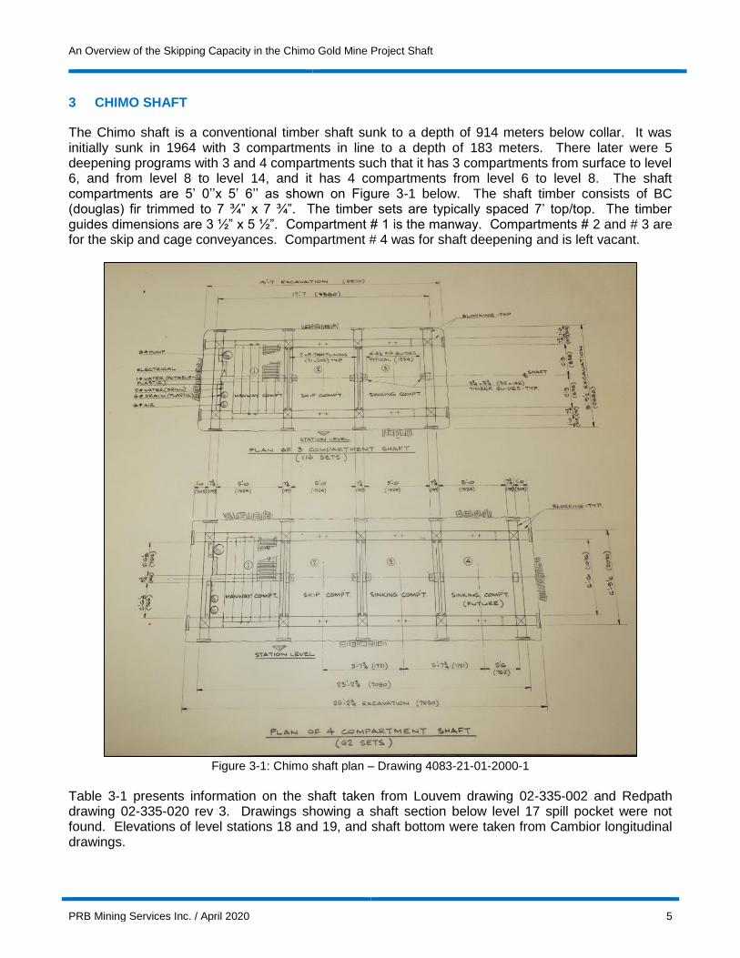
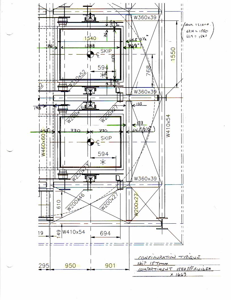
The Chimo shaft is a conventional timber shaft sunk to a depth of 914 meters below collar. It was initially sunk in 1964 with 3 compartments in line to a depth of 183 meters. There later were 5 deepening programs with 3 and 4 compartments such that it has 3 compartments from surface to level 6, and from level 8 to level 14, and it has 4 compartments from level 6 to level 8. The shaft compartments are 5’ 0’’x 5’ 6’’ as shown on Figure 3-1 below. The shaft timber consists of BC (douglas) fir trimmed to 7 ¾” x 7 ¾”. The timber sets are typically spaced 7’ top/top. The timber guides dimensions are 3 ½” x 5 ½”. Compartment # 1 is the manway. Compartments # 2 and # 3 are for the skip and cage conveyances. Compartment # 4 was for shaft deepening and is left vacant.
Figure 3-1: Chimo shaft plan – Drawing 4083-21-01-2000-1
Table 3-1 presents information on the shaft taken from Louvem drawing 02-335-002 and Redpath drawing 02-335-020 rev 3. Drawings showing a shaft section below level 17 spill pocket were not found. Elevations of level stations 18 and 19, and shaft bottom were taken from Cambior longitudinal drawings.

An Overview of the Skipping Capacity in the Chimo Gold Mine Project Shaft
PRB Mining Services Inc. / April 2020 6
Table 3-1: Chimo shaft information
Level drawings show the existence of a crusher room on level 19. There is not a ramp joining the lower levels. The existence of a loading pocket and a spill pocket below level 19 may be inferred. The location of the loading pocket and the spill pocket below level 19 may be assumed to be the same as the position of the loading pocket and spill pocket below level 17. The lip of the loading pocket is estimated to be 888 meters below collar.
Floor Depth Set Number Between
Elevation Below Collar Set Elevation Of Levels
Level m m Nbr m Compartments Δ m Comments
Collar 9,992.02 0.0 T.O.C (7) 3 0.0
9,991.71 1 9,991.71 3
Collar Bottom 9,968.85 11 9,968.85 3
1 9,916.80 75.2 35 9,917.09 3 75.2 Station pocket
2 9,878.50 113.5 52 9,878.61 3 38.3 Station pocket
3 9,823.87 168.2 79 9,823.16 3 54.6 Station pocket
4 9,780.00 212.0 99 3 43.9 Station pocket
5 9,735.50 256.5 120 3 44.5 Station pocket
6 9,688.00 304.0 142 4 47.5 Station pocket
7 9,641.60 350.4 164 4 46.4
7 LP 174 4 Loading pocket
7 Spill 199 4 Spill pocket
8 9,588.00 404.0 189 9,588.13 3 53.6
9 9,545.45 446.6 209 9,545.45 3 42.5 Lip pocket at set 215
10 9,513.45 478.6 224 9,513.45 3 32.0 Lip pocket at set 230
11 9,481.45 510.6 239 9,481.45 3 32.0
11 LP 9,460.10 249 3 Loading pocket
11 Spill Spill pocket
12 9,447.31 544.7 255 9,447.31 3 34.1 No lip pocket
13 9,415.30 576.7 270 9,415.30 3 32.0 No lip pocket
14 9,383.29 608.7 285 9,383.29 3 32.0 No lip pocket
15 9,351.28 640.7 300 9,351.28 3 32.0 No lip pocket
16 9,319.27 672.8 315 9,319.27 3 32.0 No lip pocket
17 9,287.26 704.8 330 9,287.26 3 32.0
17 LP 340 9,265.92 3 Loading pocket
17 Spill 349 9,246.72 3 Spill pocket
18 9,210.00 782.0 3 77.3
19 9,125.00 867.0 3 85.0
19 LP 9,103.65 888.4 3 Preliminary estimation
19 Spill 3 Preliminary estimation
Shaft Bottom 9,078.00 914.0 3 47.0
Notes: 1) Refer to Louvem drawing 02-335-011 for collar information.
2) Sets are distanced 2,1m top/top.
3) Information collar to level 7 taken from Louvem drawing 02-335-002.
4) Information level 7 to level 17 Spill pocket taken from Redpath drawing 02-335-020_3, July 1989.
5) Elevations of levels 18 and 19 and shaft bottom are measured from mine longitudinal drawings.
6) A shaft section drawing showing levels 18 and 19 and shaft bottom was not found.
7) T.O.C. means ''top of collar''.
8) LP means loading pocket
9) Spill means spill pocket
10) Distance from T.O.C. to level 19 LP = 888 metres
11) Shaft depth below collar = 914 metres
12) Portion of shaft @ 3 compartments = 814 metres
13) Portion of shaft @ 4 compartments = 100 metres

An Overview of the Skipping Capacity in the Chimo Gold Mine Project Shaft
PRB Mining Services Inc. / April 2020 7
4 SKIP CAPACITY AND HEADFRAME HEIGHT
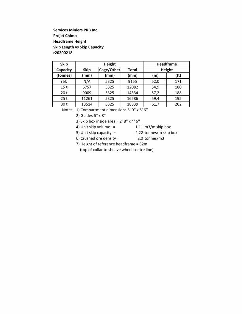
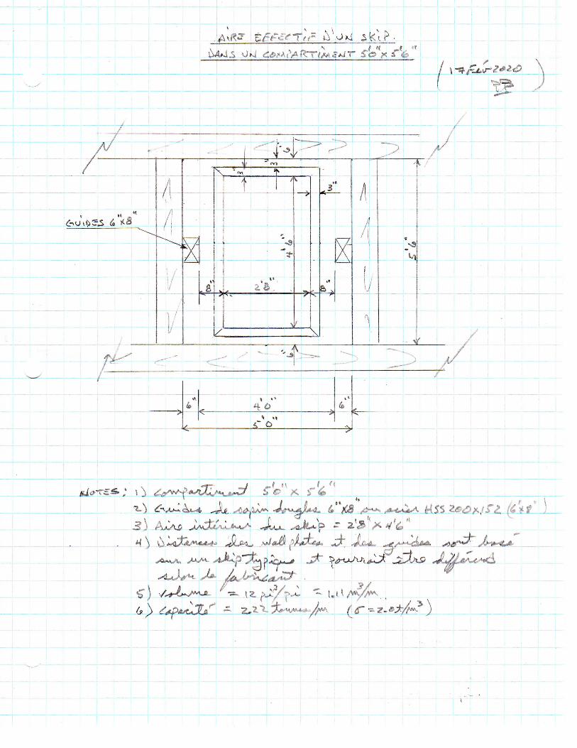
The dimensions of the Chimo shaft compartments are 5’ 0” between dividers and 5’ 6” between the wall plates. The current guides will be replaced by larger 6” x 8” guides. Using 6” x 8” guides, the space between guide faces is 4’ 0”. The space available for a conveyance is therefore 4’ 0” x 5’ 6” (1 219 mm x 1 676 mm). The typical clearance between a conveyance and wall plates is 3”. The box thickness of a bottom dump skip from outside of ribs to inside of liners is typically 3”. The distance from the inside of the skip box to the guide face is typically 8”. The inside area of a skip in the Chimo shaft is estimated to be 2’ 8” x 4’ 6” as shown on Figure 4-1. Thus, the skip would typically have an effective volume of 1.11 m3 per metre box height and a capacity of 2.22 tonnes per m of box height, using a crushed rock density of 2.0 t/m3.
Figure 4-1: Plan view of a skip box in the Chimo shaft
The conveyance will be used for skipping and for servicing and will consist of a skip/cage combination. Measurements taken on a 15 tonnes capacity skip/cage conveyance for reference shows the cage portion to have a height of 2 454 mm and the skip bottom to lower wheels and the top of cage to rope pin attachment to have a height of 2 872 mm. Taking this as a reference, the total height of the
An Overview of the Skipping Capacity in the Chimo Gold Mine Project Shaft
PRB Mining Services Inc. / April 2020 8
conveyance from rope attachment to the lower wheels would be 5 566 mm plus the height of the skip box. The total length of the reference conveyance is 9 155 mm. It has a single deck cage.
The headframe in which the reference conveyance is used has a height of 52 metres from top of collar to the centre of the sheave wheel. The distance from top of collar to the dump lip is 32 metres allowing to dump into an ore bin and a waste bin. Taking the total length of the reference conveyance, the height of the reference headframe, and the height of the skip box, the height of the headframe may be estimated for specific skip capacities.
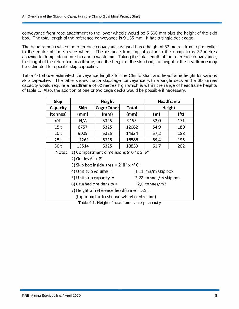
Table 4-1 shows estimated conveyance lengths for the Chimo shaft and headframe height for various skip capacities. The table shows that a skip/cage conveyance with a single deck and a 30 tonnes capacity would require a headframe of 62 metres high which is within the range of headframe heights of table 1. Also, the addition of one or two cage decks would be possible if necessary.
Table 4-1: Height of headframe vs skip capacity
Skip
Capacity Skip Cage/Other Total
(tonnes) (mm) (mm) (mm) (m) (ft)
réf. N/A 5325 9155 52,0 171
15 t 6757 5325 12082 54,9 180
20 t 9009 5325 14334 57,2 188
25 t 11261 5325 16586 59,4 195
30 t 13514 5325 18839 61,7 202
Notes: 1) Compartment dimensions 5' 0'' x 5' 6''
2) Guides 6'' x 8''
3) Skip box inside area = 2' 8'' x 4' 6''
4) Unit skip volume = 1,11 m3/m skip box
5) Unit skip capacity = 2,22 tonnes/m skip box
6) Crushed ore density = 2,0 tonnes/m3
7) Height of reference headframe = 52m
(top of collar to sheave wheel centre line)
Height
Height Headframe
An Overview of the Skipping Capacity in the Chimo Gold Mine Project Shaft
PRB Mining Services Inc. / April 2020 9
5 SKIPPING CYCLE
The skipping operation consists of two skips suspended to a hoist travelling in opposite directions between the loading station in the shaft and the dump station in the headframe on surface. As one skip travels up to surface to be emptied, the other travels down to the loading station to be loaded.
In this report, a cycle refers to a skip moving from the rest position at the headframe dump down to the loading pocket and be loaded. A typical skipping cycle is composed of the following steps:
The cycle begins when the skip at the surface dump is in fully dumped position and the skip at the loading pocket is loaded.
The skip at surface travels downward at creep speed out of the dump station. The skip is out of the dump station when the control wheels have exited the scroll plates. Creep speed for computer-controlled hoists is typically set at 180 feet per minute. At the same time, the loaded skip travels the same distance upward.
Once the empty skip is out of the dump station, both skips accelerate to reach full speed. The acceleration depends on the hoist and the motor size but is generally between 1.5 and 2.5 ft/sec2.
The skips travel at full speed until it is time to decelerate as they approach their destinations.
The skips decelerate to creep speed before the loaded skip reaches the dump station. Creep speed is typically reached 6 feet below the dump station entrance (i.e. when the skip control wheels are 6 feet below the scroll plates in the dump station).
The skips travel at creep speed until the loaded skip reaches the fully dumped position. At this point the empty skip is positioned at the loading pocket ready to be loaded.
The skip at the loading station is loaded before initiating its run up to the surface dump station.
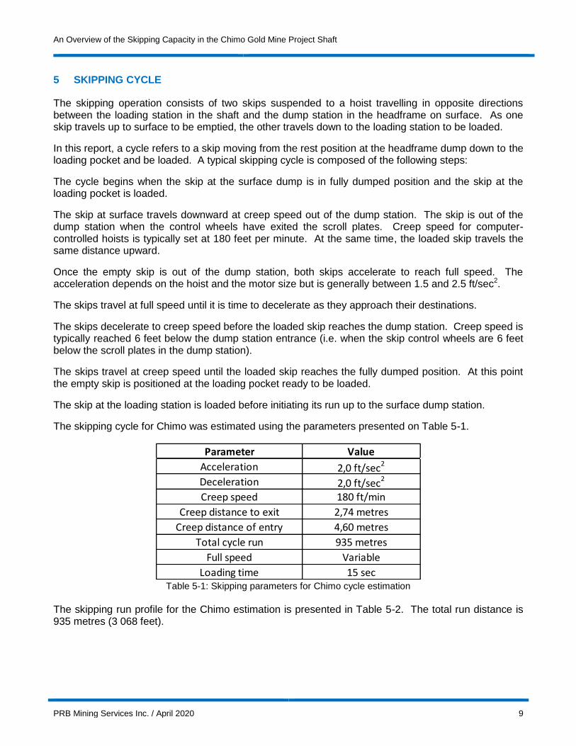
The skipping cycle for Chimo was estimated using the parameters presented on Table 5-1.
Table 5-1: Skipping parameters for Chimo cycle estimation
The skipping run profile for the Chimo estimation is presented in Table 5-2. The total run distance is 935 metres (3 068 feet).
Parameter Value
Acceleration 2,0 ft/sec2
Deceleration 2,0 ft/sec2
Creep speed 180 ft/min
Creep distance to exit 2,74 metres
Creep distance of entry 4,60 metres
Total cycle run 935 metres
Full speed Variable
Loading time 15 sec

An Overview of the Skipping Capacity in the Chimo Gold Mine Project Shaft
PRB Mining Services Inc. / April 2020 10
Table 5-2: Skip run profile
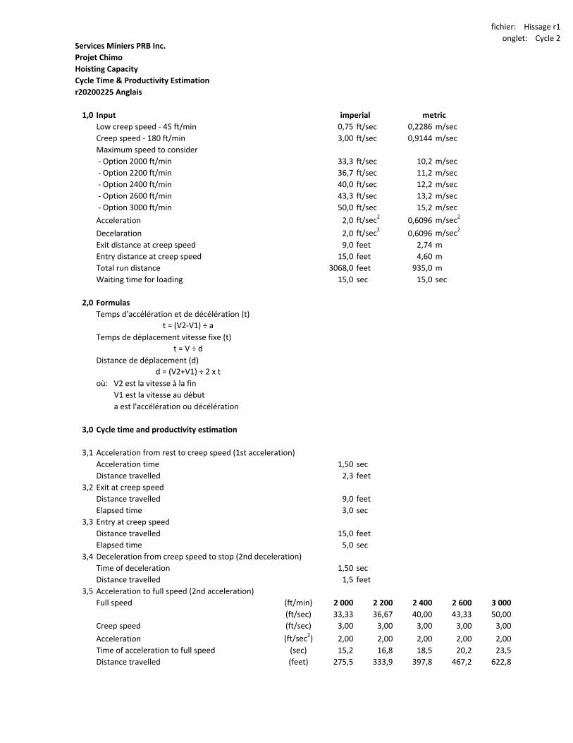
Cycle times were estimated for speeds ranging from 2 000 ft/min to 3 000 ft/min. The results are presented in Table 5-3. The cycle estimate details are presented in appendix 2. The estimated cycle time ranges from 131 to 109 seconds for speeds from 2 000 and 3 000 ft/min respectively. The nominal number of cycles ranges from 27.5 to 33.1 skips per hour.
Table 5-3: Cycle time vs hoisting speed
Metric Imperial Metric Imperial
Description m ft m ft
Control wheel skip empty 35,0 115 0 0
Scroll plates bottom 32,5 107 2,5 8
Shaft collar 0,0 0 32,5 107
Loading station -900,0 -2 953 900,0 2 953
Total run 935,0 3 068
Elevation Distance
Description Unit 2 000 2 200 2 400 2 600 3 000
Elapsed time
1st acceleration to creep speed (sec) 1,5 1,5 1,5 1,5 1,5
Exit at creep speed (sec) 3,0 3,0 3,0 3,0 3,0
2nd acceleration to full speed (sec) 15,2 16,8 18,5 20,2 23,5
Distance travelled at full speed (sec) 74,7 64,7 56,1 48,6 35,9
1st decelleration to creep speed (sec) 15,2 16,8 18,5 20,2 23,5
Entry at creep speed (sec) 5,0 5,0 5,0 5,0 5,0
2nd deceleration to stop (sec) 1,5 1,5 1,5 1,5 1,5
Waiting (loading) (sec) 15,0 15,0 15,0 15,0 15,0
Total (sec) 131,0 124,4 119,1 114,9 108,9
Cycles per hour (skip/hr) 27,5 28,9 30,2 31,3 33,1
Distance travelled
Distance during 1st acceleration (feet) 2,3 2,3 2,3 2,3 2,3
Exit at creep speed (feet) 9,0 9,0 9,0 9,0 9,0
Distance during 2nd accelaration (feet) 275,5 333,9 397,8 467,2 622,8
Distance at full speed (feet) 2 489,2 2 372,5 2 244,8 2 105,9 1 794,8
Distance during 1st deceleration (feet) 275,5 333,9 397,8 467,2 622,8
Entry at creep speed (feet) 15,0 15,0 15,0 15,0 15,0
Distance during 2nd deceleration (feet) 1,5 1,5 1,5 1,5 1,5
Total distance travelled (feet) 3 068,0 3 068,0 3 068,0 3 068,0 3 068,0
Hoist speed (feet/minute)

An Overview of the Skipping Capacity in the Chimo Gold Mine Project Shaft
PRB Mining Services Inc. / April 2020 11
6 SKIPPING CAPACITY
Tables 6-1 and 6-2 present the estimated hourly and daily skipping capacities for various hoisting speeds and skip capacities based on the cycle times presented in table 6. An efficiency factor of 85% was applied to account for unpredictable interruptions to the skipping operation. The estimate assumed an average skipping time of 10 and 12 hours per day. An automated skipping operation overseen by the hoistman is assumed allowing skipping between shifts. A detailed hoist schedule pertinent to the project will be required to validate the assumed skipping time. The hoist schedule will allocate time for transportation of personnel, servicing levels with materials and consumables, skipping, shaft inspections, and hoist inspections and maintenance.
Table 6-1: Hourly capacity vs skip capacity and hoist speed
Table 6-2: Daily skipping capacity vs skip capacity and hoist speed
Skip capacity Unit 2 000 2 200 2 400 2 600 3 000
Cycles per hour (skip/hr) 27,5 28,9 30,2 31,3 33,1
Efficiency factor 85% 85% 85% 85% 85%
15 tonnes skip (tm/hr) 350 369 385 399 422
20 tonnes skip (tm/hr) 467 492 514 532 562
25 tonnes skip (tm/hr) 584 615 642 666 703
30 tonnes skip (tm/hr) 701 738 771 799 843
Hoist speed (feet/minute)
Capacité de skip Unité 2 000 2 200 2 400 2 600 3 000
Average daily skipping time (hrs/day) 12 12 12 12 12
Efficiency factor 85% 85% 85% 85% 85%
15 tonnes skip (tm/day) 4 204 4 429 4 624 4 792 5 058
20 tonnes skip (tm/day) 5 606 5 905 6 165 6 390 6 744
25 tonnes skip (tm/day) 7 007 7 381 7 707 7 987 8 430
30 tonnes skip (tm/day) 8 409 8 857 9 248 9 585 10 116
Average daily skipping time (hrs/day) 10 10 10 10 10
Efficiency factor 85% 85% 85% 85% 85%
15 tonnes skip (tm/day) 3 504 3 691 3 853 3 994 4 215
20 tonnes skip (tm/day) 4 671 4 921 5 138 5 325 5 620
25 tonnes skip (tm/day) 5 839 6 151 6 422 6 656 7 025
30 tonnes skip (tm/day) 7 007 7 381 7 707 7 987 8 430
Notes: 1) Production numbers in shaded grey areas apply to timber and steel guides.
Other production numbers apply to steel guides only.
Hoist speed (feet/minute)

An Overview of the Skipping Capacity in the Chimo Gold Mine Project Shaft
PRB Mining Services Inc. / April 2020 12
7 HOIST CHARACTERISTICS
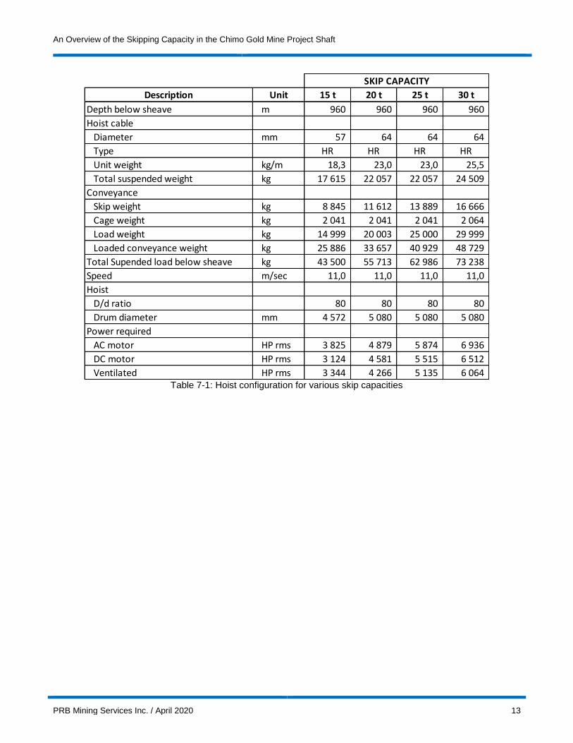
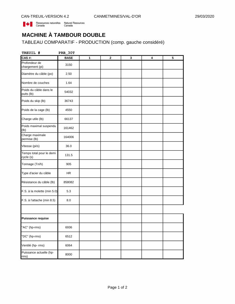
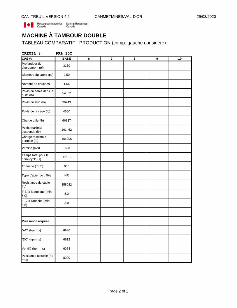
Skipping operation was analysed for skips having capacities of 15 tonnes, 20 tonnes, 25 tonnes and 30 tonnes to determine hoist drum diameter, rope diameter and motor size. The analysis assumed a hoisting depth of 3 150 feet, a hoist speed of 2 160 feet per minute and an acceleration of 2.0 feet per second square. Wire ropes were selected using a safety factor of 7.5 at the rope attachment (weight of conveyance and allowable skip load) and 5.0 at the sheave wheel (weight of conveyance, allowable skip load, and rope when conveyance is at shaft bottom) in accordance with Québec regulations, articles 288, 289, and 289.1. Typical wire rope characteristics were taken from Wire Rope Industries’ catalog on the company’s web site (https://www.bridon-bekaert.com/en-us/steel-and-synthetic-ropes/underground-mining). The wire rope analysis and data sheets are presented in appendix 3.
The drum hoist diameter was determined using a drum diameter to cable diameter ratio (D/d) of 80:1 with the exception of 100:1 for full lock coil cables (regulations article 312). CANMET simulated skipping scenarios to provide a rough estimate of the motor size required (appendix 3). The simulation assumed a single-rope drum hoist and high resistance wire ropes of standard construction (no full lock coil cable was simulated). The results of the analysis are presented in Table 7-1.
The 15 tonnes skip would require a 58 mm diameter rope and a minimum hoist drum diameter of 4 580 mm (180 inches). The 20 to 30 tonnes skips would require a 65 mm diameter rope (each of different steel grade) and a minimum hoist drum diameter of 5 080 mm (200 inches). The 25 and 30 tonnes skips may require a full lock coil cable 65 mm in diameter. The hoist drum diameter for a 65 mm full lock coil rope would be 6 500 mm (256 inches). The 25 and 30 tonnes skips approach the limit of wire rope capacities such that a multi-rope (Blair) hoist would likely be preferred. This option was not analysed. The power requirements would be similar.
New hoists currently use AC motors. The simulation suggests the required AC motor power would be between 3 825 HP rms for 15 tonnes skips and 6 940 HP rms for 30 tonnes skips.
An Overview of the Skipping Capacity in the Chimo Gold Mine Project Shaft
PRB Mining Services Inc. / April 2020 13
Table 7-1: Hoist configuration for various skip capacities
Description Unit 15 t 20 t 25 t 30 t
Depth below sheave m 960 960 960 960
Hoist cable
Diameter mm 57 64 64 64
Type HR HR HR HR
Unit weight kg/m 18,3 23,0 23,0 25,5
Total suspended weight kg 17 615 22 057 22 057 24 509
Conveyance
Skip weight kg 8 845 11 612 13 889 16 666
Cage weight kg 2 041 2 041 2 041 2 064
Load weight kg 14 999 20 003 25 000 29 999
Loaded conveyance weight kg 25 886 33 657 40 929 48 729
Total Supended load below sheave kg 43 500 55 713 62 986 73 238
Speed m/sec 11,0 11,0 11,0 11,0
Hoist
D/d ratio 80 80 80 80
Drum diameter mm 4 572 5 080 5 080 5 080
Power required
AC motor HP rms 3 825 4 879 5 874 6 936
DC motor HP rms 3 124 4 581 5 515 6 512
Ventilated HP rms 3 344 4 266 5 135 6 064
SKIP CAPACITY

An Overview of the Skipping Capacity in the Chimo Gold Mine Project Shaft
PRB Mining Services Inc. / April 2020 14
8 DISCUSSION
8.1 GUIDES VS HOIST SPEED
Shaft guides in Québec typically consist of timber (BC douglas fir) of 6’’ x 8’’ dimensions or of hollow structural steel (HSS) 6’’ x 8’’. The application of timber guides is limited to a hoist speed of 2 200 ft/min and lighter loads otherwise they tend to deteriorate rapidly and need to be replaced often. Steel guides are used for higher speeds and high loads.
Timber guides should be limited to a maximum hoisting speed of 2 200 feet per minute and 20 tonnes skips. Steel guides are not used at speeds higher than 3 000 feet per minute.
8.2 FALL ARREST SYSTEMS
Québec regulations (S-2.1, r.14 - Règlement sur la santé et la sécurité du travail dans les mines) stipulate that the maximum speed at which personnel may be transported in a mine shaft is 1 500 feet per minute. This is referred to as maximum man riding speed. The hoist skipping speed may be higher, but the hoist speed is limited to 1 500 feet per minute when in man riding mode.
Article 323 of the Québec regulations stipulates that a conveyance suspended to a single-rope drum hoist used to transport personnel must be fitted with a fall arrest system in case of rope rupture. The fall arrest system must have the capacity to stop the combined weight of the conveyance and of the allowable number of persons travelling downward at maximum man riding speed (1 500 fpm). This, however, does not apply to a conveyance suspended to a multi-rope drum hoist (Blair hoist).
All personnel transportation conveyances in Québec and Ontario currently operate on timber guides. The use of steel guides is limited to shaft compartments where conveyances are dedicated to hoisting rock only (skipping only). The fall arrest systems consist of a spring-loaded mechanism which, when released, sets steel blades into the guides cutting the timber until the conveyance is fully stopped. The blades are commonly referred to as ‘’dogs’’. The capacity of 6’’ x 8’’ timber guides to resist a fall arrest system is 15 000 lbs (6 818 kg) per guide. The dimensions of the Chimo shaft conveyance compartments are 5’ 0’’ x 5’ 6’’. With 6’’ x 8’’ guides installed, the distance between guide faces is 4’ 0‘’ and the distance between wall plates is 5’ 6’’. Compartments of these dimensions are fitted with two guides. Large service compartments, like at the Laronde no. 3 shaft, are fitted with four guides.
Fitting the Chimo conveyance compartments with two guides limits the total weight of the conveyance (skip-cage) and its allowable number of persons to 30 000 lbs (13 636 kg).
Québec regulations (article 331) stipulates that the maximum number of persons allowed in a cage with a floor area smaller than 1.86 m2 is 5.25 per m2. A cage in the Chimo shaft compartment would have an approximate area of 1.62 m2. A 2-deck cage would be allowed to transport a maximum of 18 persons. A 4-deck cage would be allowed to transport 36 peoples. For a high tonnage operation, a large cage capacity will be essential to transport personnel in a timely fashion and maximize skipping time.
Approximate skip capacities were estimated for a cage-skip conveyance travelling in a 2 guides compartment (appendix 4). The estimate used a skip capacity to skip weight ratio of 1.8, a cage weight of 390 lbs per person, and a personnel weight of 200 lbs per person. The estimate resulted in a skip capacity of 15.8 tonnes for a 2-deck cage, a skip capacity of 11.5 tonnes for a 3-deck cage, and a skip capacity of 7.2 tonnes for a 4-deck cage. The exercise is not accurate but provides an overview of the limitations of fitting the compartments with 2 timber guides. It is unlikely that a 2 guides configuration will accommodate the skipping, the material servicing and the personnel transportation requirements for a high tonnage operation.

An Overview of the Skipping Capacity in the Chimo Gold Mine Project Shaft
PRB Mining Services Inc. / April 2020 15
Skip capacities were also estimated assuming a 4 timber guides scenario where the maximum weight limitation is 60 000 lbs (27 273 kg). The exercise resulted in a skip capacity of 30 tonnes for a 4-deck cage. There may not be sufficient space to fit a 4-guides fall arrest system on a conveyance of this size. The distance of 5’ 6” between the timber wall plates limits the space in which the dogs may function. A conversation is ongoing with conveyance manufacturers on this subject.
FLSmidth Systems has developed a fall arrest system for steel guides. It is called the Cage Guardian Safety Brake (https://www.flsmidth.com/en-gb/products/cage-guardian-safety-brake). It is currently designed for a cage conveyance only. None are currently in operation in Canada. The deceleration system is an integral part of the cage. It does not use friction on the steel guides to decelerate. Rather, deceleration works within the system itself (see video at the following link: https://www.flsmidth.com/en-gb/products/cage-guardian-safety-brake#data-fancybox). Discussions are ongoing with FLSmidth Systems to apply the system to a cage-skip conveyance. A bottom dump skip would normally be preferred for Chimo. The system cannot be applied to a bottom dump skip/cage configuration. It may, however, be applied to an arc gate skip/cage configuration. Most skips in operation in Québec are of bottom dump design. Arc gate skips have an inherent obstruction around the arc gate and tend to have hang-ups when used with damp material. FL Smidth Systems opined that the arc gate skip may be an option where ore is crushed.
Wabi Iron & Steel Corp is developing a fall arrest system for steel guides. It is called Lock-N-Load (http://www.wabicorp.com/mine-equipment-division/lock-%c2%adn-%c2%adload/). It is an electric/hydraulic system activated by a slack rope situation where the conveyance is sitting on an obstruction or a rope rupture. It can also be activated by a button to hold the conveyance in position such as at a station to load or unload the cage. This can save time servicing stations by eliminating the need to chair the cage to chains in order to keep the conveyance level as the hoist cable stretches or retracts as a load is added or removed. The system is used in a few Ontario mines to timber guides as conveyance chairing system, not as a fall arrest system.
Pamphlets of these systems may be found in appendix 5. Permitting for use in Québec of both the Cage Guardian Safety Brake and the Lock-N-Load systems needs to be addressed. Québec regulations do not mention any type of fall arrest systems. Québec regulations (article 326) simply stipulate that it must be designed by a reputable engineer and a free fall test must conducted before its first use. A free fall test consists of locking the fall arrest system and letting the conveyance fall until it reaches the permitted man-riding speed (i.e. 1 500 feet per minute for Chimo) before engaging the fall arrest system. After being put into service, the fall arrest system must to be periodically inspected and drop tested (dropped from rest position).
An alternative would be to use a multi-rope hoist in which case a fall arrest system is not required because the second rope will take the load in case of failure. There is currently not any multi-rope hoist in operation in Québec or Ontario.
8.3 SERVICE AND PERSONNEL TRANSPORTATION
A high tonnage and low-grade production scenario will require a significant effort in personnel transportation and delivery of materials and consumables underground. This will have a huge impact on the time that can be dedicated to skipping of ore and waste to surface. The Chimo shaft has three small compartments of which one is a manway. The hoisting system should be selected to skip ore and waste in the least possible time. Longer skips at higher speeds are to be preferred.
The use of long skips at high speeds will require the use of steel guides. Guide alignment of the steel guide is crucial to reduce impact from the skip load to the guides and timber. The shaft timber will require a realignment to be within acceptable tolerances. After realignment, running tests with an

An Overview of the Skipping Capacity in the Chimo Gold Mine Project Shaft
PRB Mining Services Inc. / April 2020 16
accelerometer can identify areas to be corrected. The shaft timber will also need to be reinforced to resist impact from skips travelling in the shaft. Further study will be necessary to address this subject.
A steel structure may be preferable to the timber structure in place. In this case, the shaft end plates and dividers could consist of hollow structural steel (HSS) members pinned to the shaft walls at a relatively low cost compared to excavating and equipping a new shaft.
The manway in the compartment no. 1 should be replaced with a mary-ann cage conveyance dedicated to personnel transportation. This conveyance may not be used for servicing materials and consumables to levels underground. It may only be used to transport small tools workers worn on workers’ belts or bags (articles 53, 54, and 55 of the Québec regulations S-2.1, r.14). This hoisting system must be separate from the skipping system (hoist in a separate building).
The mary-ann conveyance could handle all transportation of personnel day and night removing a significant burden from the skipping system. A mary-ann cage with 4 decks could fit 36 persons.
An Overview of the Skipping Capacity in the Chimo Gold Mine Project Shaft
PRB Mining Services Inc. / April 2020 17
9 CONCLUSIONS
The analysis for the Chimo shaft concluded that a hoisting system operating at speeds between 2 000 feet per minute and 3 000 feet per minute can have a skipping rate of 27 skips per hour up to 33 skips per hour respectively.
Using skips between 15 and 30 tonnes at a speed between 2 000 and 3 000 feet per minute may have a production rate between 350 tonnes per hour to 843 tonnes per hour. The existing timber structure with timber guides will be adequate for skips of up to a 20 tonnes capacity at speeds up to 2 200 feet per minute for a production rate of 492 tonnes per hour therefore 5 905 tm/day (12 hours/day) or 4 921 tm/day (10 hours/day). At higher speeds up to 3 000 feet per minute, steel guides should be used and the shaft timber may require reinforcement.
Use of a 15 tonnes skip would require a 57 mm diameter rope. The hoist drum would have a minimum diameter of 4 572 mm (180 inches). CANMET’s simulation suggests a 3 825 HP rms AC motor would be required.
Use of 20, 25 and 30 tonnes skips would require 65 mm diameter ropes of different steel grades. The hoist drum would have a minimum diameter of 5 080 mm (200 inches). If a full lock coil rope is used for the 25 and 30 tonnes skips, the hoist drum would have a minimum diameter of 6 500 mm (256 inches). CANMET’s simulations suggest AC motor size of 4 880 HP rms, 5 880 HP rms and 6 940 HP rms respectively for the 20, 25, and 30 tonnes skips scenarios.
A high tonnage and low-grade production scenario will require a significant effort in transportation of personnel and delivery of materials and consumables underground. This will have a significant impact on the time that can be dedicated to skipping of ore and waste to surface. Longer skips and higher speeds are to be preferred.
Also, the manway should be replaced with a multi-deck mary-ann conveyance handling all transportation of personnel which would provide more time to the production hoist for skipping and servicing. A cage with 4 decks could fit 36 persons.
Use of longer skips would require steel guides and would require timber reinforcement or timber replacement with steel end plates and dividers pinned to the shaft walls. Since workers will be travelling in the skipping compartments and longer skips are preferred, use of a multi-rope hoist should be considered so a fall arrest system would not be necessary.
An Overview of the Skipping Capacity in the Chimo Gold Mine Project Shaft
PRB Mining Services Inc. / April 2020 18
10 REFERENCES
- S-2.1, r.14 - Règlement sur la santé et la sécurité du travail dans les mines, http://legisquebec.gouv.qc.ca/fr/ShowDoc/cr/S-2.1,%20r.%2014/
- NI 43-101Technical Report and Mineral Resource Estimate, Chimo Mine Project, Central Gold Corridor, GéoPointCom, July 2019, https://ressourcescartier.com/wp-content/uploads/2018/07/191218_NI43-101_Chimo-Mine-Project_Res.-Est_EN.pdf

An Overview of the Skipping Capacity in the Chimo Gold Mine Project Shaft
PRB Mining Services Inc. / April 2020 19
APPENDIX 1
Skip Capacity and Height of Headframe Analysis
Services Miniers PRB Inc.
Projet Chimo
Headframe Height
Skip Length vs Skip Capacity
r20200218
Skip
Capacity Skip Cage/Other Total
(tonnes) (mm) (mm) (mm) (m) (ft)
réf. N/A 5325 9155 52,0 171
15 t 6757 5325 12082 54,9 180
20 t 9009 5325 14334 57,2 188
25 t 11261 5325 16586 59,4 195
30 t 13514 5325 18839 61,7 202
Notes: 1) Compartment dimensions 5' 0'' x 5' 6''
2) Guides 6'' x 8''
3) Skip box inside area = 2' 8'' x 4' 6''
4) Unit skip volume = 1,11 m3/m skip box
5) Unit skip capacity = 2,22 tonnes/m skip box
6) Crushed ore density = 2,0 tonnes/m3
7) Height of reference headframe = 52m
(top of collar to sheave wheel centre line)
Height
Height Headframe


An Overview of the Skipping Capacity in the Chimo Gold Mine Project Shaft
PRB Mining Services Inc. / April 2020 20
APPENDIX 2
Cycle Time Analysis

Services Miniers PRB Inc.
Projet Chimo
Hoisting Capacity
Cycle Time & Productivity Estimation Summary
r20200225 Anglais
1,0 Cycle time and travel distance
Description Unit 2 000 2 200 2 400 2 600 3 000
Elapsed time
1st acceleration to creep speed (sec) 1,5 1,5 1,5 1,5 1,5
Exit at creep speed (sec) 3,0 3,0 3,0 3,0 3,0
2nd acceleration to full speed (sec) 15,2 16,8 18,5 20,2 23,5
Distance travelled at full speed (sec) 74,7 64,7 56,1 48,6 35,9
1st decelleration to creep speed (sec) 15,2 16,8 18,5 20,2 23,5
Entry at creep speed (sec) 5,0 5,0 5,0 5,0 5,0
2nd deceleration to stop (sec) 1,5 1,5 1,5 1,5 1,5
Waiting (loading) (sec) 15,0 15,0 15,0 15,0 15,0
Total (sec) 131,0 124,4 119,1 114,9 108,9
Cycles per hour (skip/hr) 27,5 28,9 30,2 31,3 33,1
Distance travelled
Distance during 1st acceleration (feet) 2,3 2,3 2,3 2,3 2,3
Exit at creep speed (feet) 9,0 9,0 9,0 9,0 9,0
Distance during 2nd accelaration (feet) 275,5 333,9 397,8 467,2 622,8
Distance at full speed (feet) 2 489,2 2 372,5 2 244,8 2 105,9 1 794,8
Distance during 1st deceleration (feet) 275,5 333,9 397,8 467,2 622,8
Entry at creep speed (feet) 15,0 15,0 15,0 15,0 15,0
Distance during 2nd deceleration (feet) 1,5 1,5 1,5 1,5 1,5
Total distance travelled (feet) 3 068,0 3 068,0 3 068,0 3 068,0 3 068,0
2,0 Hourly production
Skip capacity Unit 2 000 2 200 2 400 2 600 3 000
Cycles per hour (skip/hr) 27,5 28,9 30,2 31,3 33,1
Efficiency factor 85% 85% 85% 85% 85%
15 tonnes skip (tm/hr) 350 369 385 399 422
20 tonnes skip (tm/hr) 467 492 514 532 562
25 tonnes skip (tm/hr) 584 615 642 666 703
30 tonnes skip (tm/hr) 701 738 771 799 843
Hoist speed (feet/minute)
Hoist speed (feet/minute)

Services Miniers PRB Inc.
Projet Chimo
Hoisting Capacity
Cycle Time & Productivity Estimation Summary
r20200225 Anglais
3,0 Production quotidienne moyenne
Capacité de skip Unité 2 000 2 200 2 400 2 600 3 000
Average daily skipping time (hrs/day) 12 12 12 12 12
Efficiency factor 85% 85% 85% 85% 85%
15 tonnes skip (tm/day) 4 204 4 429 4 624 4 792 5 058
20 tonnes skip (tm/day) 5 606 5 905 6 165 6 390 6 744
25 tonnes skip (tm/day) 7 007 7 381 7 707 7 987 8 430
30 tonnes skip (tm/day) 8 409 8 857 9 248 9 585 10 116
Average daily skipping time (hrs/day) 10 10 10 10 10
Efficiency factor 85% 85% 85% 85% 85%
15 tonnes skip (tm/day) 3 504 3 691 3 853 3 994 4 215
20 tonnes skip (tm/day) 4 671 4 921 5 138 5 325 5 620
25 tonnes skip (tm/day) 5 839 6 151 6 422 6 656 7 025
30 tonnes skip (tm/day) 7 007 7 381 7 707 7 987 8 430
Notes: 1) Production numbers in shaded grey areas apply to timber and steel guides.
Other production numbers apply to steel guides only.
Hoist speed (feet/minute)
fichier: Hissage r1
onglet: Cycle 2Services Miniers PRB Inc.
Projet Chimo
Hoisting Capacity
Cycle Time & Productivity Estimation
r20200225 Anglais
1,0 Input
Low creep speed ‐ 45 ft/min 0,75 ft/sec 0,2286 m/sec
Creep speed ‐ 180 ft/min 3,00 ft/sec 0,9144 m/sec
Maximum speed to consider
‐ Option 2000 ft/min 33,3 ft/sec 10,2 m/sec
‐ Option 2200 ft/min 36,7 ft/sec 11,2 m/sec
‐ Option 2400 ft/min 40,0 ft/sec 12,2 m/sec
‐ Option 2600 ft/min 43,3 ft/sec 13,2 m/sec
‐ Option 3000 ft/min 50,0 ft/sec 15,2 m/sec
Acceleration 2,0 ft/sec2 0,6096 m/sec2
Decelaration 2,0 ft/sec2 0,6096 m/sec2
Exit distance at creep speed 9,0 feet 2,74 m
Entry distance at creep speed 15,0 feet 4,60 m
Total run distance 3068,0 feet 935,0 m
Waiting time for loading 15,0 sec 15,0 sec
2,0 Formulas
Temps d'accélération et de décélération (t)
t = (V2‐V1) ÷ a
Temps de déplacement vitesse fixe (t)
t = V ÷ d
Distance de déplacement (d)
d = (V2+V1) ÷ 2 x t
où: V2 est la vitesse à la fin
V1 est la vitesse au début
a est l'accélération ou décélération
3,0 Cycle time and productivity estimation
3,1 Acceleration from rest to creep speed (1st acceleration)
Acceleration time 1,50 sec
Distance travelled 2,3 feet
3,2 Exit at creep speed
Distance travelled 9,0 feet
Elapsed time 3,0 sec
3,3 Entry at creep speed
Distance travelled 15,0 feet
Elapsed time 5,0 sec
3,4 Deceleration from creep speed to stop (2nd deceleration)
Time of deceleration 1,50 sec
Distance travelled 1,5 feet
3,5 Acceleration to full speed (2nd acceleration)
Full speed (ft/min) 2 000 2 200 2 400 2 600 3 000
(ft/sec) 33,33 36,67 40,00 43,33 50,00
Creep speed (ft/sec) 3,00 3,00 3,00 3,00 3,00
Acceleration (ft/sec2) 2,00 2,00 2,00 2,00 2,00
Time of acceleration to full speed (sec) 15,2 16,8 18,5 20,2 23,5
Distance travelled (feet) 275,5 333,9 397,8 467,2 622,8
imperial metric

fichier: Hissage r1
onglet: Cycle 23,6 Deceleration to creep speed (1st deceleration)
Full speed (ft/min) 2 000 2 200 2 400 2 600 3 000
(ft/sec) 33,33 36,67 40,00 43,33 50,00
Creep speed (ft/sec) 3,00 3,00 3,00 3,00 3,00
Deceleration to creep speed (1st deceleration) (ft/sec2) 2,00 2,00 2,00 2,00 2,00
Time of deceleration to creep speed (sec) 15,2 16,8 18,5 20,2 23,5
Distance travelled (feet) 275,5 333,9 397,8 467,2 622,8
3,7 Run at full speed
Total run distance (feet) 3 068,0 3 068,0 3 068,0 3 068,0 3 068,0
Displacement of 1st acceration (feet) 2,3 2,3 2,3 2,3 2,3
Exit displacement at creep speed (feet) 9,0 9,0 9,0 9,0 9,0
Displacement of 2nd acceleration (feet) 275,5 333,9 397,8 467,2 622,8
Displacement of 1st deceleration (feet) 275,5 333,9 397,8 467,2 622,8
Entry displacement at creep speed (feet) 15,0 15,0 15,0 15,0 15,0
Displacement of 2nd deceleration (feet) 1,5 1,5 1,5 1,5 1,5
Displacement at full speed (feet) 2 489,2 2 372,5 2 244,8 2 105,9 1 794,8
Time elapsed at full speed (sec) 74,7 64,7 56,1 48,6 35,9
3,7 Total cycle time
1st acceleration to creep speed (sec) 1,5 1,5 1,5 1,5 1,5
Exit at creep speed (sec) 3,0 3,0 3,0 3,0 3,0
2nd acceleration to full speed (sec) 15,2 16,8 18,5 20,2 23,5
Displacement at full speed (sec) 74,7 64,7 56,1 48,6 35,9
1st deceleration to creep speed (sec) 15,2 16,8 18,5 20,2 23,5
Entry at creep speed (sec) 5,0 5,0 5,0 5,0 5,0
2nd deceleration to stop (sec) 1,5 1,5 1,5 1,5 1,5
Waiting time (loading) (sec) 15,0 15,0 15,0 15,0 15,0
Total (sec) 131,0 124,4 119,1 114,9 108,9
3,8 Production rate
Unit skipping cycles (skip/hr) 27,5 28,9 30,2 31,3 33,1
Nominal skipping capacity with:
15 tonnes skips (tm/hr) 412 434 453 470 496
20 tonnes skips (tm/hr) 550 579 604 626 661
25 tonnes skips (tm/hr) 687 724 756 783 826
30 tonnes skips (tm/hr) 824 868 907 940 992
Daily skipping capacity:
Average daily skipping time (hrs/jr) 12 12 12 12 12
Efficiency factor 85% 85% 85% 85% 85%
15 tonnes skips (tm/d) 4 204 4 429 4 624 4 792 5 058
20 tonnes skips (tm/d) 5 606 5 905 6 165 6 390 6 744
25 tonnes skips (tm/d) 7 007 7 381 7 707 7 987 8 430
30 tonnes skips (tm/d) 8 409 8 857 9 248 9 585 10 116
Average daily skipping time (hrs/jr) 10 10 10 10 10
Efficiency factor 85% 85% 85% 85% 85%
15 tonnes skips (tm/d) 3 504 3 691 3 853 3 994 4 215
20 tonnes skips (tm/d) 4 671 4 921 5 138 5 325 5 620
25 tonnes skips (tm/d) 5 839 6 151 6 422 6 656 7 025
30 tonnes skips (tm/jr) 7 007 7 381 7 707 7 987 8 430
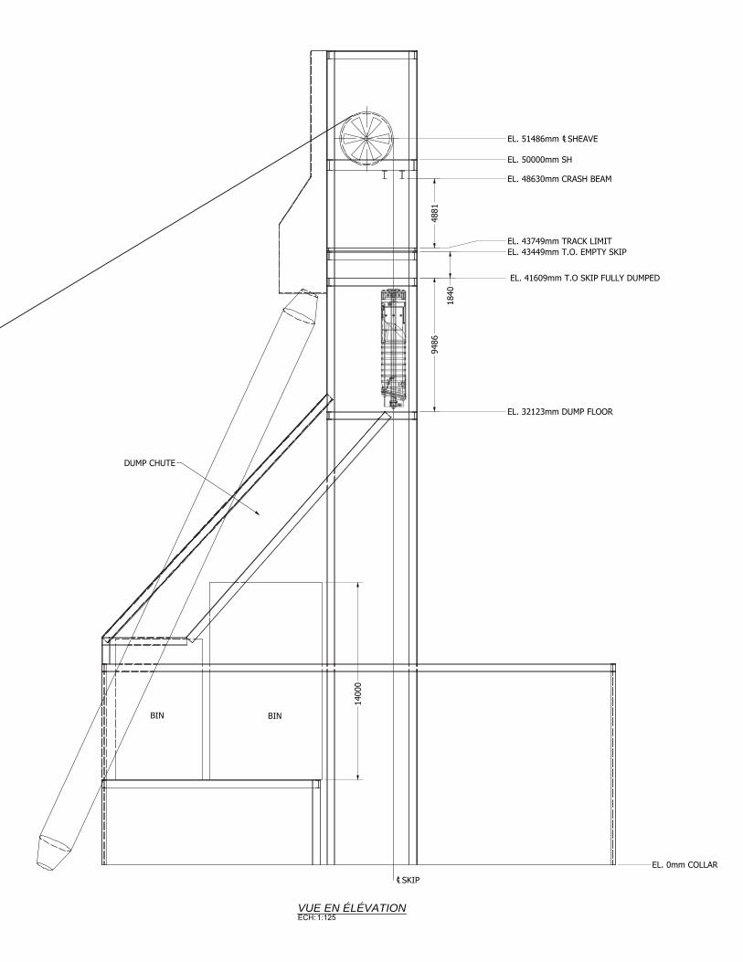
0EL. mm COLLAR
32123EL. mm DUMP FLOOR
41609 EL. mm T.O SKIP FULLY DUMPED
43449EL. mm T.O. EMPTY SKIP43749EL. mm TRACK LIMIT
48630EL. mm CRASH BEAM
50000EL. mm SH
51486EL. mm SHEAVE
9486
1840
4881
BIN BIN
DUMP CHUTE
VUE EN ÉLÉVATIONECH: 1:125
SKIP
1400
0

An Overview of the Skipping Capacity in the Chimo Gold Mine Project Shaft
PRB Mining Services Inc. / April 2020 21
APPENDIX 3
Hoist cable Analysis
And
CANMET Simulations

Services Miniers PRB Inc.
Projet Chimo
Skipping Capacity
Hoist Cable Selection
r20200326 Anglais
Description Unit 15 tm 20 tm 25 tm 25 tm 30 tm
0,0 Input
Profondeur de la molette au fond m 1 000 1 000 1 000 1 000 1 000
Ratio poids charge vs skip 1,8 1,8 1,8 1,8 1,8
1,0 Analysis at conveyance attachment
1,1 Weight
Skip (load to weight ratio 1,8:1,0) kg 8 333 11 111 13 889 13 889 16 667
Cage kg 4 550 4 550 4 550 4 550 4 550
Attaches kg 500 500 500 500 500
Conveyor total kg 13 383 16 161 18 939 18 939 21 717
Load kg 15 000 20 000 25 000 25 000 30 000
Loaded conveyor kg 28 383 36 161 43 939 43 939 51 717
1,2 Minimum nominal breaking force
Minimum safety factor 7,5 7,5 7,5 7,5 7,5
Minimum breaking strength kg 212 875 271 208 329 542 329 542 387 875
KN 2 088 2 660 3 232 3 232 3 804
1,3 Selected hoist rope characteristics
Rope typical model Lock Coil Lock Coil
Steel grade N/mm2 1 770 1 770 1 860 High Grade High Grade
Diameter mm 58 65 65 65 65
Minimum breaking strength KN 2 670 3 240 3 590 3 817 3 817
kg 272 264 330 388 366 078 389 226 389 226
Uni weight kg/m 17,0 21,4 21,4 23,8 23,8
Total weight (1 000 metres) kg 17 000 21 400 21 400 23 800 23 800
2,0 Safety factors analysis
2,1 At conveyance attachment (min. SF = 7,5)
Cable breaking strength kg 272 264 330 388 366 078 389 226 389 226
Weight under attachment kg 28 383 36 161 43 939 43 939 51 717
Safety factor 9,6 9,1 8,3 8,9 7,5
check ok ok ok ok ok
2,2 At the sheave wheel (min. FS = 5,0)
Cable breaking strength kg 272 264 330 388 366 078 389 226 389 226
Weight under sheave kg 45 383 57 561 65 339 67 739 75 517
Safety factor 6,0 5,7 5,6 5,7 5,2
Check ok ok ok ok ok
3,0 Minimum hoist drum diameter
Hoist rope diameter mm 58 65 65 65 65
Minimum Ratio D:d (regulation article 312) 80 80 80 100 100
Drum minimum diameter mm 4 640 5 200 5 200 6 500 6 500
inches 183 205 205 256 256
feet 15,2 17,1 17,1 21,3 21,3
Notes:
1) Hoist cables information are taken from Wire Rope Industries on line catalog (march 2020).
https://www.bridon‐bekaert.com/en‐us/steel‐and‐synthetic‐ropes/underground‐mining
2) Minimum safety factors are taken from Quebec regulations S‐2.1, r.14 , articles 288 and 288.1
3) D = hoist drum diameter, d = hoist rope diameter.
4) Cables for 25 and 30 tonnes scenarios are near cable industry's limits. A blair hoist should be considered.
5) Conversion kg to KN KN/kg 0,009807
Skip Capacity
Tiger Dyform 34LR/PI

Calculated Aggregate Breaking Force Calculated Minimum Breaking ForceNominal Length Mass
kg/m kN
Standard Grade Higher Grade
kN
Standard Grade
kN
Higher Grade
kN
16 1.44 261 281 218 234 17 1.63 261 281 218 234 18 1.83 331 355 276 297 19 2.04 368 395 307 330 21 2.49 449 483 375 403 21.5 2.60 465 500 388 417 22 2.73 493 530 412 443 24 3.25 587 631 490 527 26 3.81 689 740 575 618 27 4.11 743 798 620 667 29 4.74 856 921 715 769 30 5.08 916 985 765 822 31 5.42 928 998 775 833 32 5.78 1043 1121 871 936 33 6.14 1109 1192 926 995 35 6.91 1246 1339 1040 1118 37 7.72 1398 1502 1167 1255 37.5 7.93 1422 1528 1187 1276 38 8.14 1468 1578 1226 1318 40 9.02 1634 1756 1364 1466 40.5 9.25 1668 1793 1393 1497 41 9.48 1715 1844 1432 1539 42 9.95 1798 1932 1501 1614 43 10.40 1880 2021 1570 1688 44 10.90 1974 2122 1648 1772 45 11.40 2068 2223 1727 1857 46 11.90 2162 2324 1805 1940 47 12.50 2244 2413 1874 2015 48 13.00 2350 2526 1962 2109 49 13.50 2443 2626 2040 2193 51 14.70 2655 2854 2217 2383 52 15.00 2738 2943 2286 2457 53 15.80 2867 3082 2394 2574 54 16.40 2972 3195 2482 2668 55 17.00 3055 3284 2551 2742 56 17.70 3195 3435 2668 2868 57 18.30 3313 3561 2766 2973 59 19.60 3501 3763 2923 3142 60 20.30 3630 3902 3031 3258 62 21.70 3865 4155 3227 3469 64 23.10 4123 4433 3443 3701 65 23.80 4253 4572 3551 3817
NominalDiameter
mm
Lay Type Lay Direction Finish Core
Available as standard. Variable Torque and Turn characteristics available by design
Ord Right Hand Bright WSCLangs Left Hand NFC SFCGalv
• • • •
The nominal length mass values are for fully lubricated ropes.
Read Product Safety Instructions and Warnings on the use of steel wire rope before selecting or using this product.
Tiger Full LockWinding Rope
25
This table is for guidance purposes only with no guarantee or warranty (express or implied) as to its accuracy. The products described may be subject to change without notice, and should not be relied on without further advice from Bridon-Bekaert.

Read Product Safety Instructions and Warnings on the use of steel wire rope before selecting or using this product.
This table is for guidance purposes only with no guarantee or warranty (express or implied) as to its accuracy. The products described may be subject to change without notice, and should not be relied on without further advice from Bridon-Bekaert.
Calculated Minimum Breaking ForceCalculated Aggregate Breaking ForceDiameter
mm
Approx Mass
kg/m
1770 N/mm2
kN
1860 N/mm2
kN
1960 N/mm2
kN
1570 N/mm2
kN
1770 N/mm2
kN
1860 N/mm2
kN
1960 N/mm2
kN
2160 N/mm2
kN
1570 N/mm2
kN
2160 N/mm2
kN
Lay Type Lay Direction Finish CoreOrd Right Hand Bright WSCLangs Left Hand Galv
• • • • • ••
1920212223242526272829303132333435363738394041424344454647484950515253545556575859606162636465
444492542595650708769831897964
1030110011801260134014201500159016801770187019602040214022402350246025702680280029203040316032803410354036703810395040904230437045204670
1.822.022.222.442.672.903.153.413.683.964.244.544.855.175.495.836.186.546.917.287.678.088.508.929.359.7910.210.711.211.612.112.613.213.714.214.715.315.916.417.017.618.218.819.420.120.721.4
322357394432473515559604652701752804859915974
10301090115012201290136014301480155016301710179018701950203021202210229023902480257026702770287029703070318032803390350036203730
364403444488533580630681735790848907969
1030109011601230130013801450153016101670175018401920201021002200229023902490259026902790290030103120323033503460358037003830395040804210
382423467512560610662716772830891953
10101080115012201290137014501530161016901760184019302020212022102310241025102610272028302940305031603280340035203640377038904020415042804420
403446492540590643697754814875939
100010701140121012901360144015201610169017801850194020402130223023302430254026402750287029803090321033303460358037103840397041004240438045204660
248275303333364396430465502539579619661705750796843892942994
104011001140120012501310137014401500156016301700177018401910198020502130221022802360245025302610270027802870
280310342375410447485524566608652698746795845897951
100010601120118012401280135014101480155016201690176018401910199020702150223023202400249025802670276028502940304031403240
294326359394431469509551594639686734784835888943999
105011101170124013001350142014901560163017001780185019302010209021802260235024302520262027102800290030003090320033003400
310343379416454495537581626674723773826880936993
1050111011701240130013701420149015701640172017901870195020402120221022902380247025702660276028502950305031603260337034803590
342379417458501545592640690742796852910970
103010901160122012901360144015101570165017301810189019802060215022402340243025302630273028302930304031503250337034803590
The nominal length mass values are for fully lubricated ropes.
Tiger Dyform 34LR/PI
15
Hoist Rope

CAN-TREUIL-VERSION 4.2 CANMETMINES/VAL-D'OR 29/03/2020
MACHINE À TAMBOUR DOUBLETABLEAU COMPARATIF - PRODUCTION (comp. gauche considéré)
TREUIL # PRB_15TCAS #: BASE 1 2 3 4 5Profondeur de
chargement (pi)3150 3150
Diamètre du câble (po) 2.25 2.00
Nombre de couches 2.29 2.12
Poids du câble dans le
puits (lb)38834 23300
Poids du skip (lb) 19500 19500
Poids de la cage (lb) 4500 4500
Charge utile (lb) 33068 33068
Poids maximal suspendu
(lb)95902 80368
Charge maximale
permise (lb)79000 79000
Vitesse (pi/s) 36.0 36.0
Temps total pour le demi
cycle (s) 131.5 131.5
Tonnage (Tn/h) 453 453
Type d'acier du câblehaute
résistancehaute résistance
Résistance du câble (lb) 600229 428000
F.S. à la molette (min 5.0) 6.3 5.3
F.S. à l'attache (min 8.5) 10.5 7.5
Puissance requise
"AC" (hp-rms) 3825 3327
"DC" (hp-rms) 3591 3124
Ventilé (hp- rms) 3344 2909
Puissance actuelle (hp-
rms)3426 3426
Page 1 of 2

CAN-TREUIL-VERSION 4.2 CANMETMINES/VAL-D'OR 29/03/2020
MACHINE À TAMBOUR DOUBLETABLEAU COMPARATIF - PRODUCTION (comp. gauche considéré)
TREUIL # PRB_15TCAS #: BASE 6 7 8 9 10Profondeur de
chargement (pi)3150
Diamètre du câble (po) 2.25
Nombre de couches 2.29
Poids du câble dans le
puits (lb)38834
Poids du skip (lb) 19500
Poids de la cage (lb) 4500
Charge utile (lb) 33068
Poids maximal
suspendu (lb)95902
Charge maximale
permise (lb)79000
Vitesse (pi/s) 36.0
Temps total pour le
demi cycle (s) 131.5
Tonnage (Tn/h) 453
Type d'acier du câblehaute
résistance
Résistance du câble
(lb)600229
F.S. à la molette (min
5.0)6.3
F.S. à l'attache (min
8.5)10.5
Puissance requise
"AC" (hp-rms) 3825
"DC" (hp-rms) 3591
Ventilé (hp- rms) 3344
Puissance actuelle (hp-
rms)3426
Page 2 of 2

CAN-TREUIL-VERSION 4.2 CANMETMINES/VAL-D'OR 29/03/2020
MACHINE À TAMBOUR DOUBLETABLEAU COMPARATIF - PRODUCTION (comp. gauche considéré)
TREUIL # PRB_20TCAS #: BASE 1 2 3 4 5Profondeur de
chargement (pi)3150
Diamètre du câble (po) 2.50
Nombre de couches 2.53
Poids du câble dans le
puits (lb)48627
Poids du skip (lb) 25600
Poids de la cage (lb) 4500
Charge utile (lb) 44100
Poids maximal suspendu
(lb)122827
Charge maximale
permise (lb)79000
Vitesse (pi/s) 36.0
Temps total pour le demi
cycle (s) 131.5
Tonnage (Tn/h) 604
Type d'acier du câblehaute
résistance
Résistance du câble (lb) 728368
F.S. à la molette (min 5.0) 5.9
F.S. à l'attache (min 8.5) 9.8
Puissance requise
"AC" (hp-rms) 4879
"DC" (hp-rms) 4581
Ventilé (hp- rms) 4266
Puissance actuelle (hp-
rms)3426
Page 1 of 2

CAN-TREUIL-VERSION 4.2 CANMETMINES/VAL-D'OR 29/03/2020
MACHINE À TAMBOUR DOUBLETABLEAU COMPARATIF - PRODUCTION (comp. gauche considéré)
TREUIL # PRB_20TCAS #: BASE 6 7 8 9 10Profondeur de
chargement (pi)3150
Diamètre du câble (po) 2.50
Nombre de couches 2.53
Poids du câble dans le
puits (lb)48627
Poids du skip (lb) 25600
Poids de la cage (lb) 4500
Charge utile (lb) 44100
Poids maximal
suspendu (lb)122827
Charge maximale
permise (lb)79000
Vitesse (pi/s) 36.0
Temps total pour le
demi cycle (s) 131.5
Tonnage (Tn/h) 604
Type d'acier du câblehaute
résistance
Résistance du câble
(lb)728368
F.S. à la molette (min
5.0)5.9
F.S. à l'attache (min
8.5)9.8
Puissance requise
"AC" (hp-rms) 4879
"DC" (hp-rms) 4581
Ventilé (hp- rms) 4266
Puissance actuelle (hp-
rms)3426
Page 2 of 2

CAN-TREUIL-VERSION 4.2 CANMETMINES/VAL-D'OR 29/03/2020
MACHINE À TAMBOUR DOUBLETABLEAU COMPARATIF - PRODUCTION (comp. gauche considéré)
TREUIL # PRB_30TCAS #: BASE 1 2 3 4 5Profondeur de
chargement (pi)3150
Diamètre du câble (po) 2.50
Nombre de couches 1.64
Poids du câble dans le
puits (lb)54032
Poids du skip (lb) 36743
Poids de la cage (lb) 4550
Charge utile (lb) 66137
Poids maximal suspendu
(lb)161462
Charge maximale
permise (lb)164006
Vitesse (pi/s) 36.0
Temps total pour le demi
cycle (s) 131.5
Tonnage (Tn/h) 905
Type d'acier du câble HR
Résistance du câble (lb) 858082
F.S. à la molette (min 5.0) 5.3
F.S. à l'attache (min 8.5) 8.0
Puissance requise
"AC" (hp-rms) 6936
"DC" (hp-rms) 6512
Ventilé (hp- rms) 6064
Puissance actuelle (hp-
rms)8000
Page 1 of 2
CAN-TREUIL-VERSION 4.2 CANMETMINES/VAL-D'OR 29/03/2020
MACHINE À TAMBOUR DOUBLETABLEAU COMPARATIF - PRODUCTION (comp. gauche considéré)
TREUIL # PRB_30TCAS #: BASE 6 7 8 9 10Profondeur de
chargement (pi)3150
Diamètre du câble (po) 2.50
Nombre de couches 1.64
Poids du câble dans le
puits (lb)54032
Poids du skip (lb) 36743
Poids de la cage (lb) 4550
Charge utile (lb) 66137
Poids maximal
suspendu (lb)161462
Charge maximale
permise (lb)164006
Vitesse (pi/s) 36.0
Temps total pour le
demi cycle (s) 131.5
Tonnage (Tn/h) 905
Type d'acier du câble HR
Résistance du câble
(lb)858082
F.S. à la molette (min
5.0)5.3
F.S. à l'attache (min
8.5)8.0
Puissance requise
"AC" (hp-rms) 6936
"DC" (hp-rms) 6512
Ventilé (hp- rms) 6064
Puissance actuelle (hp-
rms)8000
Page 2 of 2

An Overview of the Skipping Capacity in the Chimo Gold Mine Project Shaft
PRB Mining Services Inc. / April 2020 22
APPENDIX 4
Skip Capacity vs Timber Guides Analysis

Services Miniers PRB Inc.
Projet Chimo
Hoisting capacity
Skip/cage capacity for timber guides
r20200204
1,0 Input
Guides
Assumed capacity of a 6" x 8" guide is 15 000 lbs
Capacity limit for
2 guides = 30 000 lbs = 13 636 kg
4 guides = 60 000 lbs = 27 273 kg
Cage
Maximum number of persons (article 331) 5,25 ch/m2/deck
Nominal person weight 200 lbs/personne
Assumed cage weight 390 lbs/personne
Skip
Assumed load to skip weight ratio 1,8
2,0 Analysis for 2 guides
2,1 Max weight of skip/cage/allowable persons 30 000 lbs
2,2 Cage for 5' 0" x 5' 6" compartment
a) Charge utile des personnes
Number of decks 2 decks
Floor area 1,62 m2/plancher
Allowable number of persons 5,25 ch/m2/deck
(S‐2.1, r.14 article 331) 9 ch/deck
18 ch total
Weight of allowable number of persons 200 lbs/personne
3 600 lbs Total
b) Cage weight 7 020 lbs
c) Total weight cage & persons 10 620 lbs
2,3 Skip
Max weight of skip/cage/allowable persons 30 000 lbs
Less weight of cage & persons 10 620 lbs
Allowable skip weight 19 380 lbs
Assumed load to skip weight ratio 1,8
Maximum skip capacity 34 884 lbs
15 856 kg
3,0 Analysis for 4 guides
3,1 Max weight of skip/cage/allowable persons 60 000 lbs
3,2 Cage for 5' 0" x 5' 6" compartment
a) Charge utile des personnes
Number of decks 4 decks
Floor area 1,62 m2/plancher
Allowable number of persons 5,25 ch/m2/deck
(S‐2.1, r.14 article 331) 9 ch/deck
36 ch
Weight of allowable number of persons 200 lbs/ch
7 200 lbs Total
b) Cage weight 14 040 lbs
c) Total weight cage & persons 21 240 lbs
3,3 Skip
Max weight of skip/cage/allowable persons 60 000 lbs
Less weight of cage & persons 21 240 lbs
Allowable skip weight 38 760 lbs
Assumed load to skip weight ratio 1,8
Maximum skip capacity 67 830 lbs
30 832 kg

An Overview of the Skipping Capacity in the Chimo Gold Mine Project Shaft
PRB Mining Services Inc. / April 2020 23
APPENDIX 5
Fall Arrest Systems
Cage Guardian Brake System
Lock N Load System
Cage Guardian™ Safety Brake Reliable cage-occupant protection
WE DISCOVER POTENTIAL

Suspension-failure events should never happen, but if they do, you want a safety brake system that you can count on. Unfortunately, not all safety brakes are up to the task. Wooden guides are subject to moisture and defect issues and have to be immediately replaced after every safety catch event. Add to that the fact that high-quality, consistent timber guides are becoming ever more difficult to
obtain, and you’re faced with some potentially dangerous and expensive problems.
Introducing the Cage Guardian™ Safety Brake solution from FLSmidth.
Built for control, longevity, reliability and low maintenance, the patent pending Cage Guardian Safety Brake system uses engineered steel guides and a self contained brake path. The end result? A
reliable, reusable safety brake system that you can depend on.
Keep your people safe during suspension
failure events
■Actuates automatically upon
suspension failureMechanical design ensures that the Cage Guardian Safety Brake system
actuates automatically upon slack rope or other suspension failures.
■Increased durability and reusabilitySteel guides offer increased durability
and reusability in the event of conveyance suspension failure. Simply
retrieve the cage for later redeployment.
■Meets strict mining safety regulations
The Cage Guardian Safety Brake solution is designed in accordance
with some of the world’s most stringent mine hoist safety regulations.
■Incorporates multiple redundant mechanical systems
Using multiple redundant mechanical systems — free from hydraulic, pneumatic or electrical
components relying on external energy sources, the Cage Guardian Safety Brake solution ensures a
secure ride for materials and cage occupants.
■Usable under all personnel conditions
Whether the conveyance is carrying a single occupant, a fully loaded cage or anything in between, the Cage Guardian
Safety Brake system will always perform optimally.
Key benefits

Superior Safety Your people put a lot of trust in safety brake systems. FLSmidth makes sure that our systems are worthy of that trust. That’s why we free-fall test every brake before we allow them to be used; every brake we offer is officially documented and certified, so you know that it’s up to the task before you trust it to protect your people. And, in the unlikely event that part of the brake fails, multiple redundant mechanical systems ensure that the conveyance (and everyone it’s carrying) comes to a safe stop. The Cage Guardian Safety Brake system uses a progressively increasing brake force with average deceleration rates of .9g to 2g (9 to 20 m/s/s) (29.5 to 65.6 ft/s/s, meaning cage occupants are significantly less likely to experience the kinds of injuries that come from sudden stops.
Reduced maintenance and repair costsOccupants should be your primary concern during suspension failure events. But your equipment and infrastructure is often at risk as well. Traditional safety catch systems can incur some serious damage, and when coupled with the day-to-day wear and corrosion of the mine-shaft environment, mining companies often end up spending significant amounts on safety catch repair and maintenance.
By employing engineered steel guides, the Cage Guardian Safety
Brake system offers durability unmatched by safety catches and timber guides. And when slack-rope and rope-break events do occur, components are designed to deploy without taking any damage; simply retrieve the cage back to surface, inspect, and reset the brake in preparation for any further event(s). Durable and reusable, the Cage Guardian Safety Brake solution provides a cost-effective alternative to traditional safety brake repair and maintenance expenses.
Reliable mechanical designYou shouldn’t have to depend on outside power sources to keep your people protected. The Cage Guardian Safety Brake system is completely mechanical. In the event of suspension failure, the weight of the cage itself causes the safety brake to actuate, holding the cage securely in place to await retrieval. There are no hydraulic, pneumatic or electrical components in the brakes themselves, and no external energy source is required.
This mechanical design not only allows for effective braking under all conditions, it also averts the risk of malfunction commonly associated with hydraulic and pneumatic components. This means a more secure system overall, as well as fewer repair costs for your business.

flsmidth.com/linkedin
flsmidth.com/facebook
flsmidth.com/twitter
flsmidth.com/youtube
flsmidth.com/instagram
FLSmidth
Vigerslev Allé 772500 ValbyDenmark
Tel +45 36 18 10 00Fax +45 36 30 18 20
The future is full of possibilities and you are leading the way. But it’s never a straight journey and it’s easy to lose sight of true potential. With an ally by your side who shares your ambitions and who sees your world from different angles, we will find the right way together.
For more than 135 years, we have challenged conventions and explored opportunities. Across more than 50 countries, we are 13,000 employees who combine our unique process-knowledge on projects, products and services to drive success. We develop the most advanced technology in our industries and offer market-leading product and service ranges.
Rooted in Danish values, we employ our knowledge and experience to navigate your complexity and bring better solutions to light. So no matter where in the world you are, we are here to help you discover new ground and achieve sustainable productivity enhancement.
We are the market-leading supplier of engineering, equipment and service solutions to customers in the global mining and cement industries.
We discover potential.
Bringing better solutions to light in the cement and mining industries
M 0
4-19
80
00
-4-E
NG
Mine Equipment Division
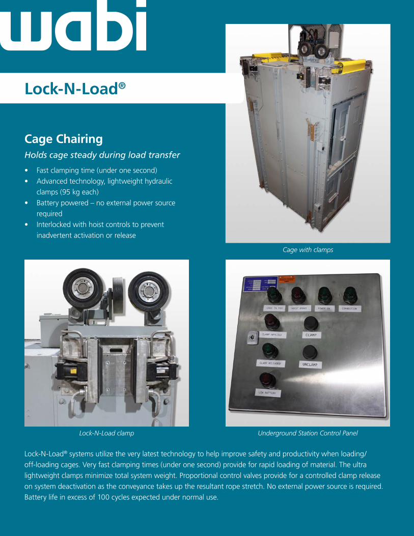
Cage ChairingHolds cage steady during load transfer
• Fastclampingtime(underonesecond)
• Advancedtechnology,lightweighthydraulic
clamps(95kgeach)
• Batterypowered–noexternalpowersource
required
• Interlockedwithhoistcontrolstoprevent
inadvertentactivationorrelease
Lock-N-Load®
Cage with clamps
Underground Station Control PanelLock-N-Load clamp
Lock-N-Load®systemsutilizetheverylatesttechnologytohelpimprovesafetyandproductivitywhenloading/
off-loadingcages.Veryfastclampingtimes(underonesecond)provideforrapidloadingofmaterial.Theultra
lightweightclampsminimizetotalsystemweight.Proportionalcontrolvalvesprovideforacontrolledclamprelease
onsystemdeactivationastheconveyancetakesuptheresultantropestretch.Noexternalpowersourceisrequired.
Batterylifeinexcessof100cyclesexpectedundernormaluse.

CERTIFIED
Wabi Iron & Steel Corp.Head Office and Manufacturing Facility:330 Broadwood Ave.New Liskeard ON Canada P0J 1P0
Tel: 705.647.4383Fax: 705.647.6954E-mail: [email protected]: wabicorp.com
ECAT Emergency Conveyance Arresting TechnologySafely arrests cage after rope severance or slack rope condition
ECAT activation mechanism
Top of cage
• Replacesoutdated“safetydogs”
• Operateswithsteelshaftguides
• DecelerationcomplieswithOntarioOHSA232(8)
• Asinglecombinedchairingandarrestingsystem
providessignificantweightsaving
Usingproventechnology,theECATsystemhasbeen
designedtooperateassimplyaspossiblewhile
providinganeffectivemeasureofprotectionin
arrestingthefallofacageafterropeseverance.
Decelerationratesprovidedaretolerabletothehuman
bodyandcomplytoOntarioOHSAregulations.The
systemhasbeencomprehensivelytested.
Ropeseveranceisdetectedbyalimitswitchlocated
inthedrawbar,whichtriggersactivationoftheECAT,
andallowshydraulicpressuretobereleasedfromthe
accumulatorstothehydraulicclamps.
Built-inredundancyincludes:
• Twotimesclampcapacitysafetyfactor
• Twoindependenthydrauliccircuits
• Two(primaryandsecondary)fallarrestactivation
switches