Embed Size (px)
Citation preview

INTERNAL CABLING GUIDELINES
Apr 2013

1
Article (1) : In the application of the provisions of these Guidelines, the terms and expressions
used herein shall express the exact meaning exhibited in both Telecommunications Regulatory
Act and its Executive Regulation, whereas the following terms and expressions shall have the
meanings shown against each, unless the text otherwise requires:
ADSL: Asymmetric Digital Subscriber Line
ANSI/TIA/EIA-568: a set of three telecommunications standards from the Telecommunications
Industry Association. The standards address commercial building cabling for telecom products
and services. The three standards are formally titled ANSI/TIA/EIA-568-B.1-2001, -B.2-2001, and
-B.3-2001.
ANSI/TIA/EIA-526-7: Optical Power Loss Measurements of Installed Single-mode Fiber Cable
ANSI/TIA/EIA-568-B.1: COMMERCIAL BUILDING TELECOMMUNICATIONS CABLING STANDARD
ANSI/TIA/EIA-568-B.1-1: Patch Cord Bend Radius
ANSI/TIA/EIA-568-B.1-2: Grounding & Bonding
ANSI/TIA/EIA-568-B.1-3: Supportable Distances for Optical Fiber
ANSI/TIA/EIA-568-B.1-4: Recognition of Category 6 & 850 Laser Optimized 50/125μm
Multimode Optical Fiber Cabling
ANSI/TIA/EIA-568-B.2: 100 OHM TWISTED PAIR CABLING STANDARDS
ANSI/TIA/EIA-568-B.2-1: Category 6
ANSI/TIA/EIA-568-B.2-2: Revisions to TIA/EIA-568-B.2
ANSI/TIA/EIA-568-B.2-3: Additional Considerations for Insertion Loss and Return Loss Pass/Fail
Determination
ANSI/TIA/EIA-568-B.2-4: Solderless Connection Reliability Requirements for Copper Connecting
Hardware
ANSI/TIA/EIA-568-B.2-5: Corrections to TIA/EIA-568-B.2-5
ANSI/TIA/EIA-568-B.3: OPTICAL FIBER STANDARDS
ANSI/TIA/EIA-606-A: Administration Standard for Commercial Telecommunications
Infrastructure
ANSI/TIA/EIA-607: Grounding and Bonding Requirements for Telecommunications in
Commercial Buildings
ANSI: American National Standards Institute
CAT-6: (Category 6 cable) is a cable standard for Gigabit Ethernet and other network physical
layers that is backward compatible with the Category 5/5e and Category 3 cable standards.
Earth Potential Rise (EPR): occurs when a large current flows to earth through earth grid
impedance.
EIA: Electronic Industries Alliance
ETP: External Termination Point
FDB: Floor Distribution Point

2
High Voltage (HV): A class of nominal system voltages equal to or greater than 100KV or less
than 230KV (IEEE Std. 241-1990, Clause 3.1.1.2)
IEC: International Electrotechnical Commission.
ILAC: the International Laboratory Accreditation Cooperation.
ITU-T G.652: Characteristics of a single-mode optical fiber cable
Lead-in Ducts: underground ducts connecting the building to the premises boundaries.
Low Voltage (LV): A class of nominal system voltages 1000V or less (IEEE Std. 241-1990, Clause
3.1.1.2)
MDB: Main Distribution Box
ODF: Optical Distribution Frame.
ONU: optical Network Unit is a device that transforms incoming optical signals into electronics
at a customer's premises in order to provide telecommunications services over an optical fiber
network.
RJ45: registered jack standard.
Router: A host that enables communication between other hosts by forwarding IP packets
based on the content of their IP destination address field.
ScTP: Screened Twisted Pair
Surge: voltage spike that affect telecommunications infrastructure.
TIA: Telecommunications Industry Association
TO: Telecommunication Outlet
UTP: Unshielded twisted pair
Article (2): It should be in every building telecommunications infrastructure to support the
telecommunications services. However, buildings in special hazard conditions such as areas
with a high risk of explosion (such as an oil refinery) or with exposure to high voltages (such as
an electricity substation) is excluded from these Guidelines provisions. Such installations should
be specially designed to meet the specific requirements of the high hazard area. Taking into
account the development of buildings infrastructure, the following provisions shall apply:
(1) All Internal Wiring designs shall support a multi service provider setting supporting up to
three service providers; even if details are not provided in these Guidelines.
(2) All the cables used in the internal wiring must be continuous. The middle joints are not
allowed.
(3) All elements of internal wiring must be labeled properly to simplify future operation and
maintenance works. Labels on elements must match the label in the documentation.
(4) Spans between the equipment running Ethernet protocol shall not exceed 100m in span.
(5) It is highly recommended that only components that have been certified by approved Labs
are used.

3
(6) Earthling of equipment and cables, both protective and functional, is properly carried out.
(7) The system must be bonded and grounded as per ANSI/TIA/EIA-607.
(8) Separation of telecommunications cabling from other non-hazardous services should
always be a minimum of 100 mm.
(9) Where a building is fitted with lightning protection, the telecommunications cables should
maintain a separation of 9m from the down-conductor of the protection system.
(10) At all times, cables should be installed in a manner so as not to impede access to other
services for maintenance and repair.
(11) Aerial cabling should be avoided.
(12) Sizes of ducts and all infra-structure equipment’s should take into account likely future
needs for cabling as well as the initial installation.
(13) Any design based on this document must clearly mention that and specify which version of
this document is followed.
(14) A Telecom Room must be provided in any compounds/ building having more than 20 unit’s
.MDB can be used instead, if the total units are less than 20.
(15) Any Material stated in these Guidelines can be replaced with any other material with same
or better quality.
In the application of these Guidelines regarding the buildings, the following provisions shall
apply:
FIRST: RESIDENTIAL PREMISES (1) Each villa shall be equipped with MDB as described in these Guidelines.
(2) Lead-in ducts must be provided from the MDB to the house boundary as described in
these Guidelines.
(3) Cables (UTP) from the MDB to Each TO shall be laid.
(4) Each room (except the wet rooms such as: Bathrooms, Kitchens, and Laundry rooms) shall
be equipped with two TO’s for voice and Data as described in these Guidelines.
One Extra Data TO shall be installed close to each TV connection Outlet.

4
MDB
CAT-6 Cable
Voice/Data TO Voice/Data TO
Voice/Data TO
ROOM 2 ROOM 3
ROOM 1
uPVC cables Duct
Fig 1: Residential Premises Wiring
SECOND: MULTI-STORIED BUILDINGS (1) Each multi-storied building shall be equipped with:
a. Telecom Room at the ground floor (can be replaced with MDB in small buildings (less than 20 units)).
5
b. FDB at each floor apart of ground floor. c. Distribution Box for each apartment/office. d. ONU: installed at apartment/office Distribution box. e. ODF: installed in the Building MDB/Telecom room. f. Cables riser and it should accommodate three service providers’ cables.
(2) Each apartment/office shall be connected using a fiber optics cable. The fiber optics cable will connect the Telecom Room, FDB and Apartment DB.
(3) Cables (UTP) from the apartment/office DB to Each TO shall be laid. (4) Lead-in ducts must be provided from the Telecom room to the plot boundaries. (5) Each room/ working area except wet rooms shall be equipped with two TO’s for voice and
Data as described in these Guidelines.
THIRD: BUSINESS PREMISES (1) Access to the telecom room shall be granted to the Service Provider’s installation &
maintenance staff. (2) Lead-in ducts must be provided from the Telecom room to the plot boundaries.
1- OFFICES (1) Offices buildings shall be equipped but not limited to with:
a. Telecom room for each floor. b. ONU: installed at each Distribution box. c. ODF: installed in the Telecom room. d. One RJ45 TO shall be dedicated for each:
Working station
Printer
Security Camera
IP phone e. One RJ11 TO shall be dedicated for each Fax machine.
2- SHOPPING CENTERS (1) Each Shopping Center shall be equipped but not limited to with:
a. Telecom Room for each floor. b. Distribution Box for each Shop/office. c. ONU: installed at each Shop Distribution box. d. ODF: installed in the all Telecom rooms.
(2) Lead-in ducts must be provided from Main Telecom room to the plot boundaries.

6
(3) Each TO shall be connected to Shop distribution box using UTP cables. (4) Each Shop shall be connected using a fiber optics cable. (5) Each shop/ Kiosks/ Stands shall be equipped with two TO’s for voice and Data.
Fig 2: Shopping Centers Wiring
FOURTH: COMPOUNDS (1) The Compound shall be equipped but not limited to with:
a. Telecom Room located in central location of the compound. b. Lead-in ducts should be provided from the telecom room to the complex
boundaries and from Telecom room to all buildings/villas. c. ODF: installed in the Telecom room.
(2) Fiber optics cables should be provided from the telecom room to each villa/ unit in the Compound.
(3) Each villa/unit (office, shop or apartment) shall be fitted but not limited to with: a. Distribution Box for each villa/Building.
b. Two TO’s for voice and data in each room and one data TO shall be installed close to each TV connection Outlet.
c. ONU: installed in each villa/unit Distribution Box.

7
FIFTH: CABLING STANDARDS (1) The building should be fitted with ducts from the Telecom Room/ MDB to each TO. (2) The conductors and terminals of the telecommunications cabling should be separated from
the terminals and conductors of the electrical power system by a minimum of 150mm or a permanent rigidly fixed barrier of insulating, or earthed conducting material.
(3) For UTP Cables, The Cable span between Patch Panel and Socket shall not exceed 90m in span.
(4) The routing of any telecommunications cable within a building should be separated from LV power cables by a minimum separation of 100mm, or by a barrier of insulating and durable material such as a joist or rafter.
(5) Where common trunking is used for telecommunications and LV power cables, the telecommunications cables should be installed in a separate channel or compartment of the trunking such that the channel is separated by a continuous barrier of insulating material.
(6) Telecommunications cables should not be routed under carpets. (7) The routing of any telecommunications cable within a building should be separated from
HV power cables by a minimum separation of 450mm for single core HV cables and 300mm for multicore HV cables.
(8) An extra length of 3 m of cable on either end for terminations should be kept. (9) During installation, pulling tension shall not exceed 110 N (approx. 11 kg).
(10) The bending radius shall be not less than 6 times the diameter of the cable. (11) The cross-section should not be deformed by clipping. (12) Pairing shall be maintained as close as possible to the wire terminations; cable sheath
removal is to be limited to 25mm maximum. (13) There shall be no kinks or twists in the cable. (14) Cable sheaths shall not be crimped or distorted by clipping.
1. TERMINATION (1) The total number of TO that may be installed in any premises is not restricted. (2) All copper connectors/TO must meet all ANSI/TIA/EIA 568-B.2-1 (supported by 4 pair, 100
ohm CAT-6 cable or higher) (3) All Fiber Connectors/TO must meet all ANSI/TIA/EIA 568-B.3 requirements. (4) A minimum of two TO shall be provided for each room (excluding wet rooms such as
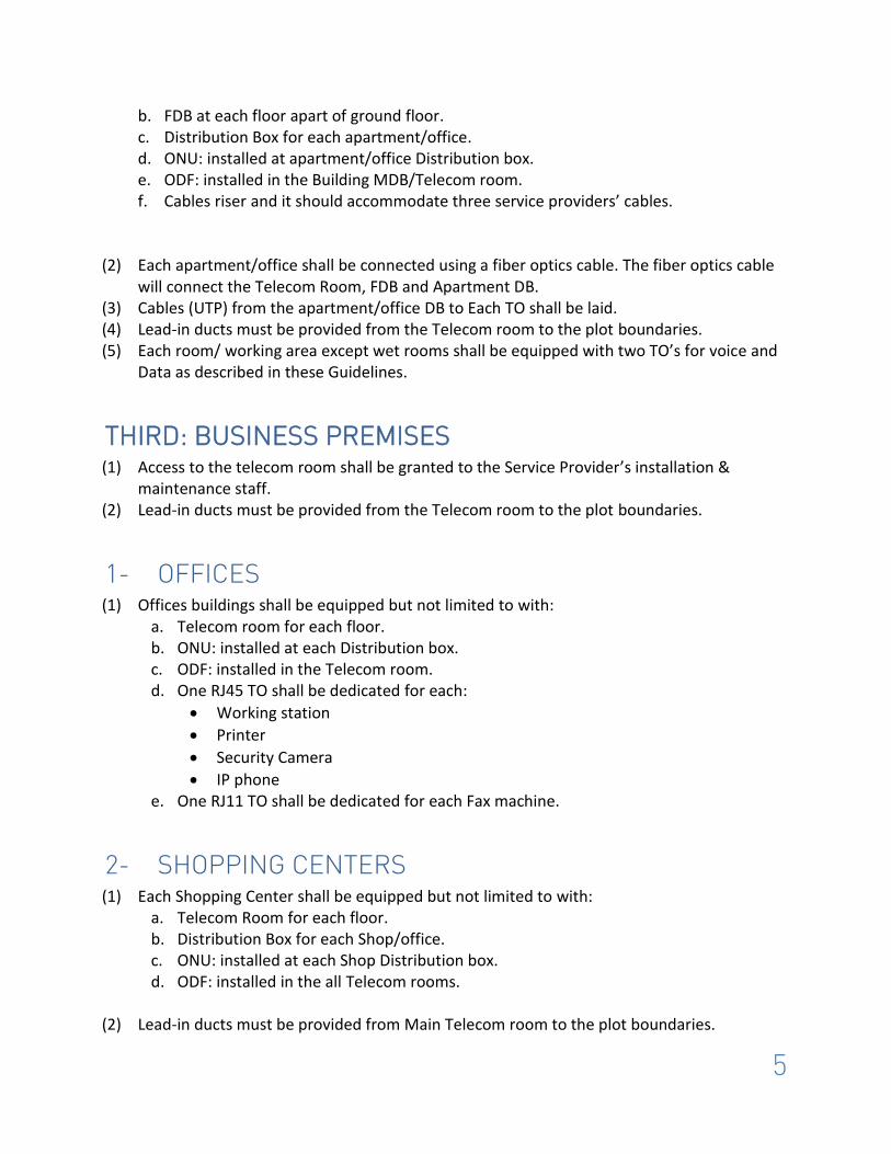
bathrooms, toilets and laundry rooms). The two TO shall be configured as: a. The left or top TO for Voice (RJ11) and labeled “VOICE” “الصوت” b. The right or bottom TO for Data (RJ45) and labeled “DATA” “ بياناتال ”
8
Fig 4: Examples of Voice/Data Sockets (TO)
(5) There should be a 240 V power outlet in close proximity to the TO for powering the connected devices.
(6) The “Power over Ethernet” (PoE) can be used for any equipment that require less than 15 W and is intended to be powered direct from the outlet (such as: Security Cameras)
(7) All the TO or other termination hardware shall not be installed where they are subject to humidity, dirty conditions, excessive heat or potential mechanical damage.
(8) TO or other termination hardware shall not be mounted less than 300 mm above the finished floor level.
(9) Each TO uses a separate run of cable to the MDB, with no looping to second or subsequent TO’s. This provides maximum flexibility to cover future needs at any TO location.
(10) Each 4 pair cable shall be terminated on an 8 position modular jack, use either T568A or T568B pin assignments as shown in the fig 5.
(11) Connecting TO’s using daisy chain/series connection is not allowed.

9
Fig 5: T568A and T568B Pin Assignments
(Source: en.wikipedia.org & fiberoptics4sale.com)
2. DISTRIBUTER BOX (1) The distribution box is a space for household service provider’s network termination
equipment. It also serves as the distribution point for all local wiring. It is essentially a cabinet or locker. This should be a telecom Cabinet with but not limited to the following functional requirements:
a. The entire distributor Boxes must be installed at least 1.2m above the finished floor level (measured between the finished floor level and the bottom edge of the cabinet).
b. Not be located in a damp area such as a bathroom, kitchen or laundry. c. Shall be at least 600 mm(high) x 350 mm (wide) x 75 mm (deep). d. Contains three 240V/13A outlets shall be provided within the DB cabinet. e. The cabinet shall have suitable ventilation or forced cooling. f. A good level of lighting should be provided to facilitate maintenance etc. g. The DB shall not be close to sources of water or heat. h. Lockable front door. i. Additional Space for future network equipment. j. Space in front of the DB for easy service access. k. Vertical & horizontal cable management. l. Earthing facility. m. See-through front door.

10
(2) There is no constraint on what hardware is fitted within the DB, as long as everything is consistent with a tidy and uncluttered installation that facilitates operation and servicing of the overall services, with no sources of electrical interference to those services.
2.1 MAIN DISTRIBUTION BOX (MDB) (1) In addition to all Distribution box functional requirements stated above. The MDB is a
Distribution Box with but not limited to the following functional requirements: a. Installed in the ground floor. b. Household service provider network termination equipment. c. Mounted immediately behind and above the ETP on the inside of the wall. However,
in existing homes, where access to the wall behind the ETP is not practical, the home distributor shall be mounted as close as possible to the ETP (on an inside wall), or arrangements should be made to shift the location of the ETP.
d. The MDB should be labeled as: “Main Telecom Distribution Box”, “ الرئيسي االتصاالتتوزيع صندوق ”
(2) The Main disruption Box may be fitted with but not limited to the following: a. Disconnect Test Point (DTP). b. Customer devices (Router, switch, etc.) c. RJ45 and RJ11 TO for testing purposes. d. RJ45 patch panel.
2.2 Floor Distribution Box (FDB) In addition to all Distribution box functional requirements as stated above, the FDB should include but not limited to the following functional requirements:
a. In multi storied buildings Floor Distribution box shall be installed in each floor other than ground floor.
b. Flats/units Distribution Boxes in the each floor should be connected to that Floor FDP via Fiber optical Cable.
c. Each FDP shall be connected to MDP via Fiber Optical Cable. d. The FDB should be labeled as :
“Floor Telecom Distribution Box”, “ طابقيال االتصاالتتوزيع صندوق ” e. The FDB shall be equipped with ODF.
2.3 PREMISES/UNITS DISTRIBUTION BOX The Premises DB should include in addition to all DB functional requirements the following functional requirements:
1- The PDB Installed in each apartment/unit. 2- Equipped with ONU.

11
3- Customer devices (Router, switch, etc.) 4- The Unit Distribution Box labeled as:
“Unit Telecom Distribution Box”, “ للوحداتاالتصاالت توزيعصندوق ”
3. CABLES
3.1 OPTICAL FIBER (1) All Optical Fiber elements must be Single Mode (SM) and at least compliant with ITU-T
G.657A and ANSI/TIA/EIA-568-B.3. (2) All optical fibers splices in internal wiring are to be “Fusion Spliced”. Typical splice
attenuation shall not exceed 0.05dB
3.2 COPPER (1) The cables must conform to a minimum of CAT6 specification. (Category 6, 100 Ohm, 4
pair 24 AWG as specified in ANSI/TIA/EIA-568-B.2-1) (2) Maximum Pulling Tension for 4 pair UTP it is 110 N (25 lbf ≈ 11.34 kilograms-force).
3.3 Minimum Bend Radius
Table 1: Cables Min Bend Radius
4. DUCTS (1) Two sizes of wire ducts are in general use depending on the amount of cable likely to be
carried. These are of PVC construction with either 50mm or 90mm internal diameter. (2) Metal ducts must be free from sharp edges and earth bonded. (3) Cables trays must be easily accessible. (4) Cables containment systems must not run through areas exposed to:
a. High Temperature;
b. Humidity;
c. Corrosive environmental conditions;
d. High voltages;
Cable Type Bend Radius
4 Pair UTP 4 X cable diameter
4 Pair ScTP 8 X cable diameter
Backbone 10 X cable diameter
Patch Cords : 4 pair UTP cables 6mm (.25")
Patch cords: 4 pair ScTP cables. 50mm (2.0")
Single mode Fiber 20 X cable diameter
12
e. Radio frequency interference (RFI);
f. Electro-magnetic interference (EMI).
(5) To prevent electromagnetic interference a minimum separation must be maintained in the cables containment systems design.
(6) Duct routes should avoid long parallel runs with other ducts or services carrying high voltages. This is to minimize Low Frequency Induction (LFI).
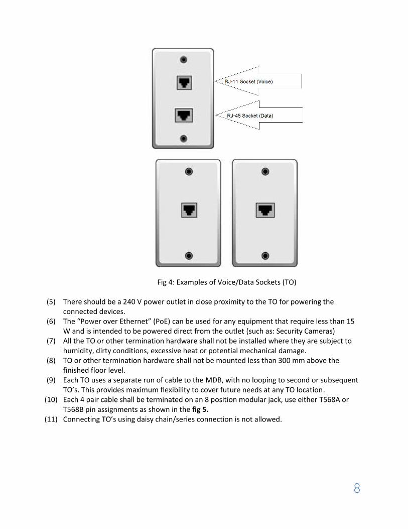
(7) There should be no more than one 90° bend in any run and runs should be kept as straight as possible.
Fig6: Right Angled Ducts
4.1 LEAD-IN DUCTS (1) The Lead-in duct should connect the Service provider main line (plot bounders) and the
Telecom Room/MDB cable junction box. (2) The lead-in ducts should be provided with the following functional requirements:
a. made from black uPVC
b. buried to a depth of 600mm below finished ground level
c. Clearly marked above ground level
d. Sloping away from the building
e. Protected by concrete when running under permanent paved surfaces
f. Sealed at each end
g. Junction box (pull box) must be installed for any right-angled or sharp bends in the
underground duct route.
(3) A continuous and strong 6 to10mm polypropylene draw rope is installed in the duct. It must be free of knots and secured at both ends of the duct, with minimum tensile strength of 1000kg.
(4) The Lead-in ducts should accommodate up to three Service providers cables.
90

13
4.2 Pits/Junction Box/ Handhole /pull box (1) Pits/Junction Box/ Handhole /pull box shall be used to permit changes in direction and
provide access for pulling cables. (2) Pits/Junction Box/ Handhole /pull box should accommodate up to three Service providers
cables.
4.3 Cable Riser (1) Cable Raiser should be provided for all multi stories buildings. (2) The cables riser should accommodate up to three Service providers cables.
5. TELECOM ROOM The Telecom Room shall meet the following requirements:
a. Good lighting, proper ventilation and air circulation.
b. 24/7granted accessible by Service Provider staff.
c. Properly accessible for personnel and for shifting equipment and tools.
d. Have a master lock for the entrance door.
e. Not close to sources of water or heat.
f. Have no windows.
g. Dedicated spaces not shared with other functions such as (electrical room or
Mechanical Room).
h. Air conditioned to maintain the temperature at 20C ± 3C (with humidity 40%-60%).
i. All metal parts of the raised floor system must be earth bonded.
j. Extra space for future network equipment.
5.1 TELECOM ROOM SIZE a. It is recommended to have at least one TR per floor.
b. The following table showing the minimum TR size.
Villas Not Required
Shopping Centers (for Ground floor) 4X3X3m
Shopping Centers (all floors but Ground floor) 2X3X3m
Residential Buildings (20-30 connections) 2X2X3m
Residential Buildings (more than 30 connections) 3X3X3m
Offices Buildings (for each floor) 2X2X3m
Compounds (15-50 Villa) 3X3X3m
Compounds (< 15 villa) 2X3X3m
Warehouses Not Required

14
Table 2: Telecom Room Sizes (Length x width x height)
6. TESTS (1) For Single mode Fiber optics the test equipment must meet ANSI/TIA/EIA-526-7. (2) All CAT-6 circuits must be tested using a test set that meets the accuracy requirements of
TIA/EIA-568-B.1 and TIA/EIA-568-B.2-1. All test requirements must be completed as specified in TIA/EIA-568-B.1 and TIA/EIA-568-B.2-1. A copy of the test results is to be provided and left with the installation documentation and certification.
(3) The Fiber Optics Cable power measurement test shall be taken between the ODF and the FTB at 1310, 1550 & 1650nm. The fiber optic circuits must be tested using a test set that meets the accuracy requirements of TIA/EIA-568-B.1 and TIA/EIA-568-B.3. All test requirements must be completed as specified in TIA/EIA-568-B.1 and TIA/EIA-568-B.3. Unless stated otherwise, tests must be performed from both ends of each circuit. Connectors must be visually inspected for scratches, pits or chips and must be re terminated if any of these conditions exist. The test results shall be kept with the building installation and certification documentation.
7. RECORDS/ DOCUMENTATIONS/ LABELING (1) All the infrastructure components must be clearly and uniquely labeled. Labels on
elements must match the label in the documentation (Labels Book) and as-built drawings. (2) The building records shall include but not limited to the following:
Building location information (e.g., Building Number and Way Number)
A list of all TO’s and their locations in the building.
Contact information.
A copy of labels reference document (Labels Book).
As-built drawings. All above documents must be kept in the telecom room/MDB.
7.1 Labeling (1) All the labeling work must be done in accordance with ANSI/TIA/EIA-606-A. (2) As a minimum the following must be reflected in the Labels:
a. The size, color, and contrast of all labels should be selected to ensure that the identifiers are easily read.
b. Labels should be visible during the installation of and normal maintenance of the infrastructure.
c. Labels should be resistant to the environmental conditions (such as moisture, heat, or ultraviolet light)

15
d. All labels shall be printed or generated by a mechanical device, and shall not be written by hand.
(3) The cable shall be labeled at both ends. (4) For the Patch panel, each position must be labeled with a unique designator
corresponding to the TO location. (5) The following can be used as an example of labeling system:
a) Cables Labels Ex: CAB-XX
Where XX= Cable Number b) TO Labels
Ex: Where XX= Room Number YY= TO Number
c) Devices Ex:
Where XX=Room Number YY=Device number
(6) The Labels reference document (Labels Book) should contain the description of each label
in the building. The following can be used as example of the Label book format:
No.
Cables Description Type
1
CAB-001
From: Telecom Room, Patch Panel, Socket 13 CAT-6 To: Room Number 2, TO-0201
TO-XXYY المعلومات
Data
DEV-XXYY جهاز التوجيه
Router
16
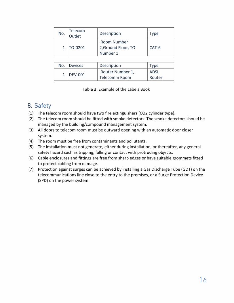
No. Telecom Outlet
Description Type
1 TO-0201 Room Number 2,Ground Floor, TO Number 1
CAT-6
No. Devices Description Type
1 DEV-001 Router Number 1, Telecomm Room
ADSL Router
Table 3: Example of the Labels Book
8. Safety (1) The telecom room should have two fire extinguishers (CO2 cylinder type). (2) The telecom room should be fitted with smoke detectors. The smoke detectors should be
managed by the building/compound management system. (3) All doors to telecom room must be outward opening with an automatic door closer
system. (4) The room must be free from contaminants and pollutants. (5) The installation must not generate, either during installation, or thereafter, any general
safety hazard such as tripping, falling or contact with protruding objects. (6) Cable enclosures and fittings are free from sharp edges or have suitable grommets fitted
to protect cabling from damage. (7) Protection against surges can be achieved by installing a Gas Discharge Tube (GDT) on the
telecommunications line close to the entry to the premises, or a Surge Protection Device (SPD) on the power system.