Embed Size (px)
Citation preview

PROJECT MANUAL FOR
Intermountain Medical Center
Dialysis Home Care Remodel
74 West Vine Street
Murray, Utah 84107
for
INTERMOUNTAIN HEALTHCARE
Construction Documents September 30, 2021
NJRA Architects, Inc. 5272 South College Dr. Murray, Utah 84123 Telephone: (801) 364-9259

Intermountain Healthcare Dialysis Home Care Remodel
Intermountain Medical Center
PROJECT MANUAL INDEX PAGE 1
Project Specifications Manual
Title Page
Project Manual Index
Bidding and Contract Requirements
Bid Response Form
Application and Certificate for Payment (AIA Document G-702-1992)
Certificate of Substantial Completion (AIA Document G704-2017)
Contractor’s Affidavit of Release of Liens (AIA Document G706A-1994)
General Conditions
Intermountain Healthcare General Conditions of the Contract (2019)
Intermountain Responsibility Matrix
Sample Addendum
Sample Architect’s Supplemental Instructions
Sample Proposal Request
Sample Submittal Review
Technical Specifications
Architectural
DIVISION 1 - GENERAL REQUIREMENTS
01 10 00 Summary
01 29 00 Payment Procedures
01 31 00 Project Management and Coordination
01 31 10 Field Engineering
01 33 00 Submittal Procedures
01 40 00 Quality Requirements
01 50 00 Temporary Facilities and Controls
01 60 00 Product Requirements
01 76 00 Guaranties and Warranties
01 77 00 Closeout Procedure
01 78 23 Operation and Maintenance Data
01 78 39 Project Record Documents
01 79 00 Cleaning
DIVISION 2 – EXISTING CONDITIONS
02 41 19 Selective Demolition
DIVISION 3 - CONCRETE
03 53 00 Concrete Topping

Intermountain Healthcare Dialysis Home Care Remodel
Intermountain Medical Center
PROJECT MANUAL INDEX PAGE 2
DIVISION 5 - METALS
05 40 00 Cold-Formed Metal Framing
DIVISION 6 - WOOD AND PLASTICS
06 10 00 Rough Carpentry
06 41 23 Interior Architectural Woodwork
DIVISION 7 – THERMAL AND MOISTURE PROTECTION
07 21 00 Building Insulation
07 84 00 Firestopping
07 92 00 Joint Sealants
DIVISION 8 – DOORS AND WINDOWS
08 11 13 Hollow Metal Doors and Frames
08 14 00 Flush Wood Doors
08 51 13 Aluminum Windows
08 71 00 Door Hardware
08 80 00 Glazing
DIVISION 9 - FINISHES
09 22 16 Non-Structural Metal Framing
09 22 20 Acoustical Insulation
09 29 00 Gypsum Board
09 51 13 Acoustical Panel Ceilings
09 65 19 Resilient Flooring
09 68 13 Carpet Tile
09 91 23 Interior Painting
DIVISION 10 – SPECIALTIES
10 26 00 Wall and Door Protection
Mechanical
DIVISION 21 - FIRE SUPPRESSION
21 10 10 Water Based Fire Suppression System
DIVISION 22 - PLUMBING
22 05 00 Common Work Results for Plumbing
22 05 13 Common Motor Requirements for Plumbing Equipment

Intermountain Healthcare Dialysis Home Care Remodel
Intermountain Medical Center
PROJECT MANUAL INDEX PAGE 3
22 05 18 Escutcheons for Plumbing Piping
22 05 23 General-Duty Valves for Plumbing Piping
22 05 29 Hangers & Supports for Plumbing Piping Equipment
22 05 53 Identification for Plumbing Piping and Equipment
22 07 19 Plumbing Piping Insulation
22 11 19 Domestic Water Piping Specialties
22 13 19 Sanitary Waste Piping Specialties
22 40 00 Plumbing Fixtures
DIVISION 23 - HEATING, VENTILATING, AND AIR CONDITIONING
23 01 00 Mechanical Requirements
23 01 50 Temporary Use of Equipment and Systems
23 05 00 Common Work Result for HVAC
23 05 93 Testing, Adjusting and Balancing for HVAC
23 07 13 Duct Insulation
23 30 01 Common Duct Requirements
23 31 13 Metal Ducts
23 33 00 Air Duct Accessories
23 37 13 Diffusers, Registers and Grilles
DIVISION 26 - ELECTRICAL
26 05 19 LOW-VOLTAGE ELECTRICAL POWER CONDUCTORS AND CABLES
26 05 29 HANGERS AND SUPPORTS FOR ELECTRICAL SYSTEMS
26 05 33 RACEWAYS AND BOXES FOR ELECTRICAL SYSTEMS
26 05 44 SLEEVES AND SLEEVE SEALS FOR ELECTRICAL RACEWAYS AND CABLING
26 05 53 IDENTIFICATION FOR ELECTRICAL SYSTEMS
26 09 23 LIGHTING CONTROL DEVICES
26 51 19 LED INTERIOR LIGHTING
27 00 00 GENERAL COMMON CONDITIONS FOR ALL COMMUNICATION SECTIONS
27 01 00 OPERATION AND MAINTENANCE OF COMMUNICATIONS SYSTEMS
27 01 13 WARRANTY, PRODUCT AND SYSTEM
27 01 19 FIELD TESTING AND REPORTING
27 01 33 SHOP DRAWINGS, PRODUCT DATA, SAMPLES DESIGN RECORDS & EXISTING
CONDITIONS
27 01 43 QUALIFICATIONS AND REQUIRED TRAINING FOR CONTRACTORS AND
INSTALLERS
27 01 71 RESPONSIBILITY AND WORKMANSHIP OF CONTRACTOR
27 05 00 COMMON WORK RESULTS FOR COMMUNICATONS
27 05 26 GROUNDING AND BONDING FOR COMMUNICATIONS SYSTEMS
27 05 28 PATHWAYS FOR COMMUNICATONS SYSTEMS
27 05 29 HANGERS AND SUPPORTS FOR COMMUNICATION SYSTEMS
27 05 33 CONDUITS AND BACK BOXES FOR COMMUNICATION SYSTEMS
27 05 36 CABLE TRAY FOR COMMUNICATIONS SYSTEMS

Intermountain Healthcare Dialysis Home Care Remodel
Intermountain Medical Center
PROJECT MANUAL INDEX PAGE 4
27 05 43 UNDERGROUND DUCTS, UTILITY POLES, AND RACEWAYS FOR
INTERBUILDING/CAMPUS
CABLE ROUTING
27 05 53 IDENTIFICATION FOR LOW-VOLTAGE CABLES AND LABELING
27 11 19 TERMINATION BLOCKS AND PATCH PANELS
27 15 00 HORIZONTAL CABLING
27 15 13 COPPER CABLE
27 15 43 FACEPLATES AND CONNECTORS
27 16 19 PATCH CABLES
27 52 23 NURSE CALL SYSTEM
27 60 01 APPENDIX 01 – DEVIATION REQUEST PROCESS
27 60 02 APPENDIX 02 – DOCUMENT REFRESH PROCESS
27 60 03 APPENDIX 03 – DATA CENTER, TEC, TDR PART NUMBERS
27 60 04 APPENDIX 04 – REFERENCE STANDARDS
27 60 05 APPENDIX 05 – DEFINITIONS AND ABBREVIATIONS
27 60 06 APPENDIX 06 – MATERIAL SUPPLIERS
27 60 07 APPENDIX 07 – SIEMON CERTIFIED INSTALLATION FIRMS
27 60 08 APPENDIX 08 – LEAD WALL PENETRATIONS
Intermountain Healthcare Dialysis Home Care Remodel
Intermountain Medical Center
INTERMOUNTAIN PROJECT NAME Day Month Year – A/E Firm Project# BID FORM PERMIT SET SECTION 00 4000 - PAGE 1
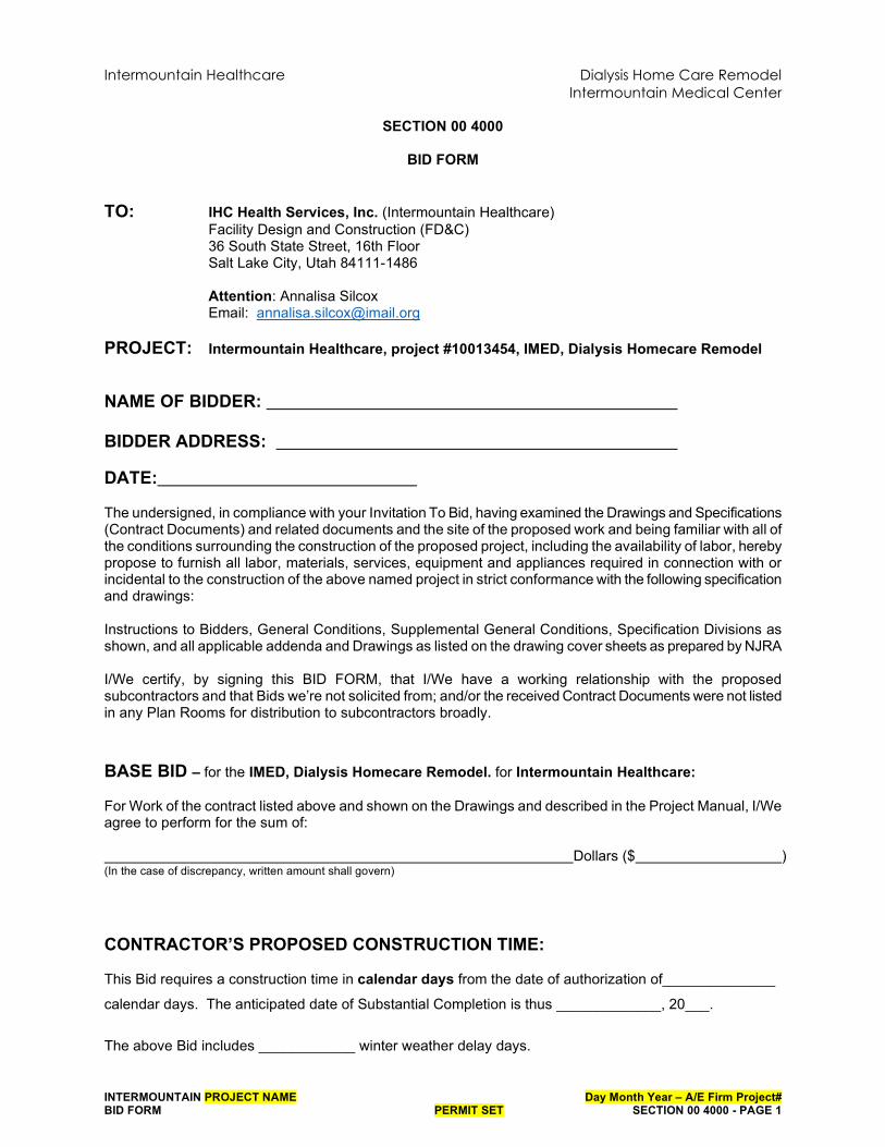
SECTION 00 4000
BID FORM
TO: IHC Health Services, Inc. (Intermountain Healthcare) Facility Design and Construction (FD&C) 36 South State Street, 16th Floor
Salt Lake City, Utah 84111-1486 Attention: Annalisa Silcox Email: [email protected]
PROJECT: Intermountain Healthcare, project #10013454, IMED, Dialysis Homecare Remodel
NAME OF BIDDER:
BIDDER ADDRESS:
DATE: The undersigned, in compliance with your Invitation To Bid, having examined the Drawings and Specifications (Contract Documents) and related documents and the site of the proposed work and being familiar with all of the conditions surrounding the construction of the proposed project, including the availability of labor, hereby propose to furnish all labor, materials, services, equipment and appliances required in connection with or incidental to the construction of the above named project in strict conformance with the following specification and drawings: Instructions to Bidders, General Conditions, Supplemental General Conditions, Specification Divisions as shown, and all applicable addenda and Drawings as listed on the drawing cover sheets as prepared by NJRA I/We certify, by signing this BID FORM, that I/We have a working relationship with the proposed subcontractors and that Bids we’re not solicited from; and/or the received Contract Documents were not listed in any Plan Rooms for distribution to subcontractors broadly.
BASE BID – for the IMED, Dialysis Homecare Remodel. for Intermountain Healthcare: For Work of the contract listed above and shown on the Drawings and described in the Project Manual, I/We agree to perform for the sum of: Dollars ($ ) (In the case of discrepancy, written amount shall govern)
CONTRACTOR’S PROPOSED CONSTRUCTION TIME: This Bid requires a construction time in calendar days from the date of authorization of______________
calendar days. The anticipated date of Substantial Completion is thus _____________, 20___.
The above Bid includes ____________ winter weather delay days.

Intermountain Healthcare Dialysis Home Care Remodel
Intermountain Medical Center
INTERMOUNTAIN PROJECT NAME Day Month Year – A/E Firm Project# BID FORM PERMIT SET SECTION 00 4000 - PAGE 2
ALTERNATES: Alternate #1 Additional cost to complete the project in two phases as described on overall plan sheet A110. For Work of the contract listed above and shown on the Drawings and described in the Project Manual as Add Alternate #1, I/We agree to perform for the sum of: Dollars ($ ) (In the case of discrepancy, written amount shall govern)
Alternate #2 Additional cost to replace existing ceiling lights at Exam room 1, 2 & 3 as described in the construction documents. For Work of the contract listed above and shown on the Drawings and described in the Project Manual as Add Alternate #2, I/We agree to perform for the sum of: Dollars ($ ) (In the case of discrepancy, written amount shall govern)
ALLOWANCES: None
ADDENDA: I/We acknowledge receipt of the following addenda for the above noted project: ___/___/___/___/___
SCHEDULE OF VALUES: I/We have attached with this Bid Form our Schedule of Values (Section 00 4373) which reflects the above Base Bid. We submit this for Owner review of subcontractors that are being proposed for this Project.
TYPE OF ORGANIZATION: (Corporation, Partnership, Individual, etc.) SEAL (If a Corporation) Respectfully Submitted,
Name of Bidder
Authorized Signature

Document G702TM – 1992Application and Certificate for Payment
AIA Document G702™ – 1992. Copyright © 1953, 1963, 1965, 1971, 1978, 1983 and 1992 by The American Institute of Architects. All rights reserved. WARNING: This AIA® Document is protected by U.S. Copyright Law and International Treaties. Unauthorized reproduction or distribution of this AIA® Document, or any portion of it, may result in severe civil and criminal penalties, and will be prosecuted to the maximum extent possible under the law. This document was produced by AIA software at 17:26:32 ET on 05/20/2019 under Order No. 0077529913 which expires on 03/27/2020, and is not for resale.User Notes: (3B9ADA60)
1
APPLICATION NO: 001 Distribution to:PERIOD TO:
TO OWNER:
PROJECT:
CONTRACT FOR: CONTRACT DATE: FROM
CONTRACTOR:
VIA ARCHITECT:
PROJECT NOS: / /
OWNER:
ARCHITECT:
CONTRACTOR:
FIELD:
OTHER :
CONTRACTOR'S APPLICATION FOR PAYMENTApplication is made for payment, as shown below, in connection with the Contract.Continuation Sheet, AIA Document G703, is attached.
1. ORIGINAL CONTRACT SUM ................................................................................. $0.00
The undersigned Contractor certifies that to the best of the Contractor's knowledge, information and belief the Work covered by this Application for Payment has been completed in accordance with the Contract Documents, that all amounts have been paid by the Contractor for Work for which previous Certificates for Payment were issued and payments received from the Owner, and that current payment shown herein is now due.
2. NET CHANGE BY CHANGE ORDERS .................................................................. $0.00 CONTRACTOR:3. CONTRACT SUM TO DATE (Line 1 ± 2) ............................................................. $0.00 By: Date: 4. TOTAL COMPLETED & STORED TO DATE (Column G on G703) .................. $0.00 State of: 5. RETAINAGE: County of:
0 % of Completed Work a.(Column D + E on G703) $0.00
Subscribed and sworn to before me this day of
0 % of Stored Materialb.(Column F on G703) $0.00 Notary Public:
Total Retainage (Lines 5a + 5b or Total in Column I of G703) .................. $0.00 My Commission expires:
6. TOTAL EARNED LESS RETAINAGE .................................................................... $0.00 ARCHITECT'S CERTIFICATE FOR PAYMENT(Line 4 Less Line 5 Total)
7. LESS PREVIOUS CERTIFICATES FOR PAYMENT ............................................. $0.00(Line 6 from prior Certificate)
8. CURRENT PAYMENT DUE .......................................................................... $0.00
In accordance with the Contract Documents, based on on-site observations and the data comprising this application, the Architect certifies to the Owner that to the best of the Architect's knowledge, information and belief the Work has progressed as indicated, the quality of the Work is in accordance with the Contract Documents, and the Contractor is entitled to payment of the AMOUNT CERTIFIED.
9. BALANCE TO FINISH, INCLUDING RETAINAGE AMOUNT CERTIFIED ...................................................................................... $0.00(Line 3 less Line 6) $0.00 (Attach explanation if amount certified differs from the amount applied. Initial all figures on this
Application and on the Continuation Sheet that are changed to conform with the amount certified.)CHANGE ORDER SUMMARY ADDITIONS DEDUCTIONS ARCHITECT:Total changes approved in previous months by Owner $0.00 $0.00 By: Date: Total approved this Month $0.00 $0.00
TOTALS $0.00 $0.00 NET CHANGES by Change Order $0.00
This Certificate is not negotiable. The AMOUNT CERTIFIED is payable only to the Contractor named herein. Issuance, payment and acceptance of payment are without prejudice to any rights of the Owner or Contractor under this Contract.
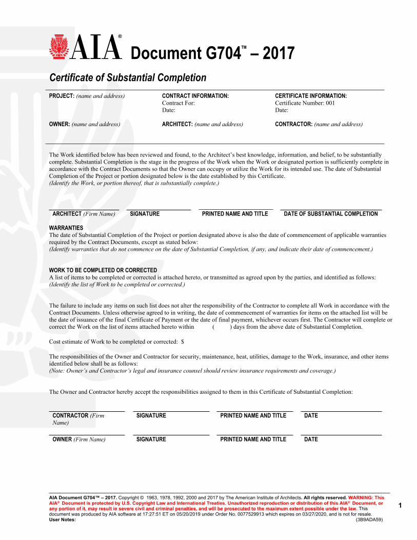
Document G704TM – 2017Certificate of Substantial Completion
AIA Document G704™ – 2017. Copyright © 1963, 1978, 1992, 2000 and 2017 by The American Institute of Architects. All rights reserved. WARNING: This AIA® Document is protected by U.S. Copyright Law and International Treaties. Unauthorized reproduction or distribution of this AIA® Document, or any portion of it, may result in severe civil and criminal penalties, and will be prosecuted to the maximum extent possible under the law. This document was produced by AIA software at 17:27:51 ET on 05/20/2019 under Order No. 0077529913 which expires on 03/27/2020, and is not for resale.User Notes: (3B9ADA59)
1
PROJECT: (name and address) CONTRACT INFORMATION: CERTIFICATE INFORMATION: Contract For: Certificate Number: 001 Date: Date:
OWNER: (name and address) ARCHITECT: (name and address) CONTRACTOR: (name and address)
The Work identified below has been reviewed and found, to the Architect’s best knowledge, information, and belief, to be substantially complete. Substantial Completion is the stage in the progress of the Work when the Work or designated portion is sufficiently complete in accordance with the Contract Documents so that the Owner can occupy or utilize the Work for its intended use. The date of Substantial Completion of the Project or portion designated below is the date established by this Certificate.(Identify the Work, or portion thereof, that is substantially complete.)
ARCHITECT (Firm Name) SIGNATURE PRINTED NAME AND TITLE DATE OF SUBSTANTIAL COMPLETION
WARRANTIESThe date of Substantial Completion of the Project or portion designated above is also the date of commencement of applicable warranties required by the Contract Documents, except as stated below:(Identify warranties that do not commence on the date of Substantial Completion, if any, and indicate their date of commencement.)
WORK TO BE COMPLETED OR CORRECTEDA list of items to be completed or corrected is attached hereto, or transmitted as agreed upon by the parties, and identified as follows:(Identify the list of Work to be completed or corrected.)
The failure to include any items on such list does not alter the responsibility of the Contractor to complete all Work in accordance with the Contract Documents. Unless otherwise agreed to in writing, the date of commencement of warranties for items on the attached list will be the date of issuance of the final Certificate of Payment or the date of final payment, whichever occurs first. The Contractor will complete or correct the Work on the list of items attached hereto within ( ) days from the above date of Substantial Completion.
Cost estimate of Work to be completed or corrected: $
The responsibilities of the Owner and Contractor for security, maintenance, heat, utilities, damage to the Work, insurance, and other items identified below shall be as follows: (Note: Owner’s and Contractor’s legal and insurance counsel should review insurance requirements and coverage.)
The Owner and Contractor hereby accept the responsibilities assigned to them in this Certificate of Substantial Completion:
CONTRACTOR (Firm Name)
SIGNATURE PRINTED NAME AND TITLE DATE
OWNER (Firm Name) SIGNATURE PRINTED NAME AND TITLE DATE

Document G706ATM – 1994Contractor's Affidavit of Release of Liens
AIA Document G706A™ – 1994. Copyright © 1982 and 1994 by The American Institute of Architects. All rights reserved. WARNING: This AIA® Document is protected by U.S. Copyright Law and International Treaties. Unauthorized reproduction or distribution of this AIA® Document, or any portion of it, may result in severe civil and criminal penalties, and will be prosecuted to the maximum extent possible under the law. This document was produced by AIA software at 17:28:24 ET on 05/20/2019 under Order No. 0077529913 which expires on 03/27/2020, and is not for resale.User Notes: (3B9ADA7A)
1
PROJECT: (Name and address) ARCHITECT’S PROJECT NUMBER: CONTRACT FOR: TO OWNER: (Name and address) CONTRACT DATED:
OWNER: ARCHITECT:
CONTRACTOR: SURETY: OTHER:
STATE OF: COUNTY OF:
The undersigned hereby certifies that to the best of the undersigned's knowledge, information and belief, except as listed below, the Releases or Waivers of Lien attached hereto include the Contractor, all Subcontractors, all suppliers of materials and equipment, and all performers of Work, labor or services who have or may have liens or encumbrances or the right to assert liens or encumbrances against any property of the Owner arising in any manner out of the performance of the Contract referenced above.
EXCEPTIONS:
SUPPORTING DOCUMENTS ATTACHED HERETO: CONTRACTOR: (Name and address)1. Contractor's Release or Waiver of Liens,
conditional upon receipt of final payment.
BY: (Signature of authorized representative)
2. Separate Releases or Waivers of Liens from Subcontractors and material and equipment suppliers, to the extent required by the Owner, accompanied by a list thereof.
(Printed name and title)
Subscribed and sworn to before me on this date:
Notary Public: My Commission Expires:

Intermountain General Conditions – 2/2020 1
GENERAL CONDITIONS
1. General Provisions 2. Intermountain 3. A/E 4. Contractor 5. Subcontractors 6. Protection of Persons and Property 7. Modifications, Request for Information, Proposed
Change Orders, and Claims Process
8. Payments and Completion 9. Tests and Inspections, Substantial and Final
Completion, Uncovering, Correction of Work, and Guaranty Period
10. Insurance and Bonds 11. Miscellaneous Provisions 12. Termination or Suspension of the Contract
1. GENERAL PROVISIONS.
1.1 Basic Definitions.
“Adverse Weather”: Weather conditions that are seasonably abnormal and could not reasonably have been anticipated.
“A/E”: Generally, the licensed architect (or architecture firm) or engineer (or engineering firm) for the Project. For Contracts where the design professional is an interior designer, landscape subconsultant or other design professional, “A/E” will be deemed to refer to that design professional. If the type of design professional is not subject to professional licensure requirements, the professional must meet the prevailing standards in the State in which the Project is located for the applicable practice. When Intermountain elects not to engage an A/E for a Project, Intermountain will be considered the A/E for the Project.
“A/E’s Agreement”: Unless the context requires otherwise, the agreement executed by A/E and Intermountain
for the Project.
“Addenda”: Written or graphic instruments issued before the opening of Bids, which clarify, correct or change
the bidding documents or the Contract Documents.
“ASI”: A Supplemental Instruction issued by A/E to Contractor, which may result in clarifications or minor
changes in the Work, but which does not affect the Contract Time or the Contract Sum.
“Bid”: The offer of the bidder submitted on the prescribed form setting forth the proposed stipulated sum for
the Work to be performed.
“Bonds”: The bid bond, payment and performance bonds, and other instruments of security.
“Change Order”: A written instrument signed by Intermountain and Contractor, stating their agreement for
changes to the Contract as specified on the required Intermountain change order form.
“Claim”: A dispute, demand, assertion or other matter arising in connection with the Contract or the Project
submitted by Contractor or a Subcontractor at any tier in accordance with these General Conditions. A
requested amendment, requested Change Order, or a Construction Change Directive (CCD) is not a Claim unless
agreement cannot be reached in accordance with the procedures in these General Conditions.
“Construction Change Directive” or “CCD”: A written order signed by Intermountain, directing a change in the
Work, and stating a proposed basis for adjustment, if any, in the Contract Sum or Contract Time, or both.
Intermountain may by Construction Change Directive, without invalidating the Contract, order changes in the
Work within the general scope of the Contract consisting of additions, deletions or other revisions; even if it may
impact the Contract Sum and Contract Time.
“Contract”: The Contract Documents form the Contract for Construction.
“Contract Documents”: The documents identified as such in the Contractor’s Agreement.

Intermountain General Conditions – 2/2020 2
“Contract Sum”: The amount stated in the Contractor’s Agreement payable by Intermountain to Contractor for
performance of the Work under the Contract Documents.
“Contract Time”: The Contract Time means the period of time for Contractor’s Substantial Completion of the
Work to be established as set forth in the Contractor’s Agreement.
“Contractor”: The person or entity identified as the “Contractor” in the Contractor’s Agreement.
“Contractor’s Agreement”: The “Contractor’s Agreement” means the Construction Manager/General Contractor
Agreement or the General Contractor Agreement for a Stipulated Sum, as applicable, executed by Contractor
and Intermountain for the Project.
“Contractor’s Direct Costs”: Actual costs incurred by the Contractor for labor, materials, equipment, insurance,
bonds, Subcontractors and on-site supervision. They do not include labor costs for project managers or other
off-site administration.
“Day” or “Days”: Calendar day unless otherwise specified.
“Defective”: Work that does not conform to the Contract Documents or does not meet the requirements of any
inspection, referenced standard, code, test or approval referred to in the Contract Documents or by applicable
law, or has been damaged.
“Director”: Intermountain’s Executive Director of Design & Construction unless the context requires otherwise.
Director may include a designee selected by the Director for a specific function.
“Drawings”: The construction drawings identified in the Contractor’s Agreement.
“Intermountain”: IHC Health Services, Inc., operating through its Department of Facility Design and
Construction. Unless the context requires otherwise, Intermountain is the “Owner” as that term is commonly
referred to in the construction industry.
“Intermountain Representative” or “Owner’s Representative”: The person identified as such in the Contract
Documents.
“Inspection” (or any derivative): A review of the Project, including but not limited to a visual review of the Work
to ascertain if the Work is in accordance with the Contract Documents, including all applicable building codes
and construction standards.
“Invitation to Bid”: Intermountain’s solicitation or request to a contractor to provide a Bid.
“Modification”: (1) Change Order, (2) Construction Change Directive, or (3) ASI.
“Notice to Proceed”: A document prepared by Intermountain authorizing Contractor to commence Work on the
Project. It is deemed issued upon delivery to Contractor or upon being sent by Intermountain to the address for
Contractor’s specified in the Bid or Proposal.
“Partial Use”: Placing a portion of the Work in service for the purpose for which it is intended (or a related
purpose) before reaching Substantial Completion for all the Work. Partial Use does not constitute “substantial
completion.”
“Product Data”: Illustrations, standard schedules, performance charts, instructions, brochures, diagrams and
other information furnished by Contractor to illustrate materials or equipment for some portion of the Work.
“Project”: Generally identified and defined in the Contractor’s Agreement and Contract Documents. It includes
all of the Work to be performed under the Contract Documents.
“Project Manual” (for construction): The volume of assembled Specifications for the Work, which may include
the bidding/proposal requirements, sample forms, and General or Supplementary Conditions of the Contract.
Intermountain General Conditions – 2/2020 3
“Proposal”: A/E’s or Contractor’s response to Intermountain’s Request for Proposal.
“Proposal Request” or “PR”: A written request submitted to Contractor for a proposal to resolve an issue as part
of the Change Order or Contract Modification process.
“Proposed Change Order” or “PCO”: An informal request by Contractor to Intermountain Representative to
commence the Contract Modification Process. It will not be considered a “Claim.” The PCO may be related to
any potential or actual delay, disruption, unforeseen condition or materials or any other matter for which
Contractor intends to seek additional monies or time.
“Request for Information” or “RFI”: A request by Contractor to A/E for information, direction or clarification
regarding the Contract Documents, plans or specifications.
“Request for Proposal” or “RFP”: Intermountain’s solicitation for Contractor Proposals.
“Sales Tax” and/or “Use Tax”: Unless the context requires otherwise, the sales tax or use tax collected or to be
collected by any Federal or State Tax Commission as well as by any special district, local government or political
subdivision.
“Samples”: Physical examples, which illustrate materials, equipment or workmanship and establish standards by
which the Work will be judged.
“Shop Drawings”: Drawings, diagrams, schedules and other data specially prepared for the Work by Contractor
or a Subcontractor, Sub-subcontractor, manufacturer, supplier or distributor to illustrate some portion of the
Work.
“Specifications”: The portion of the Contract Documents consisting of the written requirements for materials,
equipment, construction systems, standards, installation and workmanship for the Work, and for performance
of related systems and services.
“Subcontractor”: Any person or entity that has a direct contract with Contractor, including any trade contractor
or specialty contractor, and/or with any other Subcontractor at any tier to provide labor or materials for the
Work.
“Subcontractor’s Direct Costs”: Actual costs incurred by a Subcontractor for labor, materials, equipment,
insurance, bonds, lower-tier Subcontractors and supervision.
“Substantial Completion”: Completion of the Work or designated portion thereof in accordance with the
Contract Documents to a point sufficient to allow Intermountain to occupy and use the Work for its intended
purposes, including without limitation all systems shall be fully functional and operate as designed, and the A/E’s
certification that Contractor has achieved Substantial Completion of the Work. The date of Substantial
Completion is the date certified as such by the A/E in accordance with the Contract Documents.
“Work”: All labor, materials, tools, equipment, construction and services required by the Contract Documents.
1.2 Correlation and Intent of Contract Documents.
1.2.1 The intent of the Contract Documents is to require Contractor to provide all labor, materials, equipment, construction, and services necessary for the proper execution and completion of the Work. The Contract Documents are complementary and what is required by any one will be as binding as if required by all. Contractor will perform the Work in accordance with the requirements expressly set forth in or reasonably inferable from the Contract Documents.
1.2.2 The organization of the Contract Documents is not intended to control Contractor in dividing the Work among Subcontractors or to establish the extent of the Work to be performed by any trade.
1.2.3 Words used in the Contract Documents that have well known technical or trade meanings are used therein in accordance with such recognized meanings.

Intermountain General Conditions – 2/2020 4
1.2.4 In the interest of brevity, the Contract Documents may omit modifying words such as "all" and "any" and articles such as "the" and "an," but the fact that a modifier or an article is absent from one statement and appears in another is not intended to affect the interpretation of either statement.
1.3 Ownership and Use of Contract Documents. The Drawings, the Project Manual, and copies thereof are the property of Intermountain. Contractor will not use these documents on any other project. Contractor may retain one copy of the Drawings and the Project Manual as a contract record set and will return or destroy all remaining copies following final completion of the Work.
1.4 Public Statements Regarding Project. Contractor will not make any statements or provide any information to the media about the Project without the prior written consent of Intermountain. If Contractor receives any requests for information from media, Contractor will refer such requests to Intermountain.
1.5 Ownership and Use of Renderings and Photographs. Renderings representing the Work are the property of Intermountain. All photographs of the Work, whether taken during performance of the Work or at completion, are the property of Intermountain. Intermountain reserves all rights including copyrights to renderings and photographs of the Work. No renderings or photographs will be used or distributed without written consent of Intermountain.
1.6 Confidentiality / Property Rights.
1.6.1 All Drawings, Specifications and other documents prepared by A/E are and will remain the property of Intermountain, and Intermountain will retain all common law, statutory and other reserved rights with respect thereto. These documents were prepared and are intended for use as an integrated set for the Project which is the subject of the Contractor’s Agreement and constitute works made for hire. Contractor will not modify or use Contract Documents on any other project without the prior written consent of Intermountain. Intermountain may withhold its consent in its absolute discretion. Any non-permissive use or modification, by Contractor, Contractor’s Subcontractors at any tier or anyone for whose acts Contractor is liable, will be at Contractor’s sole risk. Contractor will hold harmless and indemnify Intermountain from and against any and all claims, actions, suits, costs, damages, loss, expenses and attorney fees arising out of such non-permissive use or modification by Contractor. Contractor and Subcontractors are granted a limited license to use and reproduce applicable portions of the Drawings, Specifications and other documents prepared by A/E or Intermountain appropriate to and for use in the execution of their Work under the Contract Documents. All copies made under this license will bear the statutory copyright notice, if any, shown on the Drawings, Specifications and other documents prepared by A/E or Intermountain. Submittals or distributions necessary to meet official regulatory requirements or for other purposes relating to completion of the Project are not to be construed as a publication in derogation of Intermountain’s copyright or other reserved rights.
1.6.2 In addition, Contractor will ensure that Contractor, Subcontractors, and the employees, agents and representatives of Contractor and its Subcontractors maintain in strict confidence, and will use and disclose only as authorized by Intermountain all Confidential Information of Intermountain that Contractor receives in connection with the performance of the Contract. Notwithstanding the foregoing, Contractor may use and disclose any information to the extent required by an order of any court or authority having jurisdiction, but only after it has notified Intermountain and Intermountain has had an opportunity to obtain reasonable protection for such information in connection with such disclosure. For purposes of the Contract, “Confidential Information” means:
1.6.3 The name or address of any affiliate, customer or contractor of Intermountain or any information concerning the transactions of any such person with Intermountain;
1.6.4 Any information relating to contracts, agreements, business plans, budgets or other financial information of Intermountain to the extent such information has not been made available to the public by Intermountain; and

Intermountain General Conditions – 2/2020 5
1.6.5 Any other information that is marked or noted as confidential by Intermountain at the time of its
disclosure.
1.7 Comply with Intellectual Property Rights of Others. Contractor represents and warrants that no Work (with its means, methods, goods, and services attendant thereto), provided to Intermountain will infringe or violate any right of any third party and that Intermountain may use and exploit such Work, means, methods, goods, and services without liability or obligation to any person or entity (specifically and without limitation, such Work, means, methods, goods, and services will not violate rights under any patent, copyright, trademark, or other intellectual property right or application for the same).
2. INTERMOUNTAIN.
2.1 Information and Services Required of Intermountain.
2.1.1 Intermountain Representative. Intermountain will designate an Intermountain Representative authorized to act in Intermountain’s behalf with respect to the Project. Intermountain or such authorized representative will furnish to Contractor information or services Intermountain is required to furnish under the Contract Documents within a reasonable time in order to avoid a delay in the orderly and sequential progress of the Work.
2.1.2 Specialists and Inspectors. Intermountain reserves the right (but without obligation to provide building inspection services. This may include ‘routine’ and ‘special’ inspections. Intermountain may assign an inspector or specialist to note deviations from, or necessary adjustments to, the Contract Documents or to report deficiencies or defects in the Work. The inspector or specialist’s activities in no way relieve Contractor of the responsibilities set forth in the Contract Documents.
2.1.3 Inspections. Intermountain and its representatives will have the right to inspect any portion of the Work wherever located at any time.
2.1.4 Surveys and Legal Description. Intermountain will furnish surveys describing the property lines and benchmarks for grading. Contractor will review this information, including the surveys and any provided geotechnical studies, and compare such information with observable physical conditions and the Contract Documents.
2.1.5 Prompt Information and Services. Upon receipt of a written request from Contractor, Intermountain will furnish information or services under Intermountain’s control with reasonable promptness to avoid delay in the orderly progress of the Work.
2.1.6 Copies of Drawings and Project Manuals (for Construction). Unless otherwise provided in the Contract Documents, Contractor will be furnished electronic copies of Drawings and Project Manuals for Contractor’s use in connection with the execution of the Work for the Project. Contractor will be responsible for making any further needed copies of the Construction Documents, subject to the copyright requirements.
2.2 Construction by Intermountain or By Separate Contractors.
2.2.1 Intermountain’s Right to Perform Construction and to Award Separate Contracts.
a. In General. Intermountain reserves the right to perform construction or operations related to the Project with Intermountain’s own forces, and to award separate contracts related to the Project or other construction or operations on the site.
b. Coordination and Revisions. Intermountain will provide for coordination of the activities of Intermountain’s own forces and of each separate contractor with the Work of Contractor, who will cooperate with them. Contractor will promptly notify in writing if any such independent action will in any way compromise Contractor’s ability to meet Contractor’s responsibilities under the Contract. Contractor will participate with other separate contractors and Intermountain in reviewing their construction schedules when directed to do so. Contractor will make any revisions to the construction schedule and Contract Sum deemed necessary after a

Intermountain General Conditions – 2/2020 6
joint review and agreement by Intermountain. The construction schedules will then constitute the schedules to be used by Contractor, separate contractors and Intermountain until subsequently revised.
2.2.2 Mutual Responsibility.
a. Contractor Coordination. Contractor will afford Intermountain and separate contractor(s) a reasonable opportunity for delivery and storage of their materials and equipment and performance of their activities and will connect and coordinate Contractor’s construction and operations with theirs where applicable.
b. Reporting Problems to Intermountain. If part of Contractor’s Work depends on work by Intermountain or a separate contractor, Contractor will, before proceeding with that portion of the Work, inspect and promptly report in writing to Intermountain apparent discrepancies or defects in workmanship that would render it unsuitable for proper execution, performance, or results. Failure of Contractor to so inspect and make this report will constitute an acceptance and acknowledgment that Intermountain’s or separate contractors completed or partially completed construction is fit and proper to receive Contractor’s Work, except as to defects in workmanship not then reasonably discoverable.
c. Costs. Costs caused by delays or by improperly timed activities or Defective construction will be borne by the responsible party in accordance with the procedures and provisions of the Contract Documents.
d. Contractor Remedial Work. Contractor will promptly remedy damage caused by Contractor or any Subcontractor to completed or partially completed work of Intermountain or of separate contractors or to the property of Intermountain or separate contractors and subcontractors.
e. Intermountain's Right to Clean Up. If a dispute arises among Contractor and separate contractors as to the responsibility under their separate contracts for maintaining the Project free from waste materials and rubbish, Intermountain may clean the Project, allocate the cost among those responsible as Intermountain and A/E determine to be just, and withhold such cost from any amounts due or to become due to Contractor.
3. A/E.
3.1 A/E’s Administration of the Contract.
3.1.1 In General. A/E assists Intermountain with the administration of the Contract as described in the Contract Documents.
3.1.2 Site Visits. Site visits or inspections by A/E, Intermountain or any Intermountain representative will in no way limit or affect Contractor’s responsibility to comply with all the requirements and the overall design concept of the Contract Documents as well as all applicable laws, statutes, ordinances, resolutions, codes, rules, regulations, orders and decrees. A/E will promptly submit to Intermountain a written report subsequent to each site visit.
3.1.3 Communications Facilitating Contract Administration. Except as authorized by Intermountain or as otherwise provided in the Contract Documents, including these General Conditions, A/E and Contractor will communicate through the Intermountain Representative on issues regarding the timing of the Work, cost of the Work, and scope of the Work. Contractor will comply with communication policies agreed upon at any pre-construction meeting with Intermountain. Communications by and with A/E sub-consultants will be through A/E. Communications by and with Subcontractors will be through Contractor. Communications by and with separate contractors will be through Intermountain.
3.1.4 A/E May Reject Work, Order Inspection, Tests. A/E will have the authority to reject Work which, based upon A/E’s knowledge or what may be reasonably inferred from A/E’s site observations and review of data, does not conform to the Contract Documents or is damaged or rendered unsuitable.
Intermountain General Conditions – 2/2020 7
Whenever A/E considers it necessary or advisable for implementation of the intent of the Contract Documents, A/E will have the authority to require additional inspections or testing of the Work in accordance with the provisions of the Contract Documents, whether or not such Work is fabricated, installed or completed. However, neither this authority of A/E nor a decision made in good faith either to exercise or not to exercise such authority will give rise to a duty or responsibility of A/E to Contractor, Subcontractors, their agents or employees or other persons performing portions of the Work, including separate contractors.
3.1.5 A/E Review Contractor’s Submittals.
a. Contractor will submit shop drawings, product data, and samples and other submittals required by the Contract Documents to A/E as required by the approved submittal schedule.
b. A/E will review and approve or take other appropriate action upon Contractor’s submittals such as Shop Drawings, Product Data and Samples, but only for the purpose of checking for conformance with the information and design concepts expressed in the Contract Documents. A/E action taken on a submittal will not constitute a Modification of the Contract.
c. A/E’s action will be taken no later than fifteen (15) Days following A/E’s receipt of the submittal, unless agreed to otherwise by Contractor and Intermountain.
d. Review of such submittals is not conducted for the purpose of determining the accuracy and completeness of other details such as dimensions and quantities or for substantiating instructions for installation or performance of equipment or systems, all of which remain the responsibility of Contractor as required by the Contract Documents.
e. A/E’s review of Contractor’s submittals will not relieve Contractor of the obligations under the Contract Documents.
f. A/E’s review will not constitute approval of safety precautions or, unless otherwise specifically stated by A/E, of any construction means, methods, techniques, sequences or procedures.
g. A/E’s approval of a specific item will not indicate approval of an assembly of which the item is a component.
h. When professional certification of performance characteristics of materials, systems or equipment is required by the Contract Documents, A/E will be entitled to rely upon such certifications to establish that the materials systems or equipment will meet the performance criteria required by the Contract Documents.
3.2 Ownership and Use of A/E’s Drawings, Specifications and Other Documents. All Drawings, Specifications and other documents prepared by A/E are and will remain the property of Intermountain, and Intermountain will retain all common law, statutory and other reserved rights with respect thereto. These documents were prepared and are intended for use as an integrated set for the Project which is the subject of the Contractor’s Agreement and constitute works made for hire. Contractor will not modify or use Contract Documents on any other project without the prior written consent of Intermountain. Intermountain may withhold its consent in its absolute discretion. Any non-permissive use or modification, by Contractor, Contractor’s Subcontractors at any tier or anyone for whose acts Contractor is liable, will be at Contractor’s sole risk. Contractor will hold harmless and indemnify Intermountain from and against any and all claims, actions, suits, costs, damages, loss, expenses and attorney fees arising out of such non-permissive use or modification by Contractor. Contractor and Subcontractors are granted a limited license to use and reproduce applicable portions of the Drawings, Specifications and other documents prepared by A/E or Intermountain appropriate to and for use in the execution of their Work under the Contract Documents. All copies made under this license will bear the statutory copyright notice, if any, shown on the Drawings, Specifications and other documents prepared by A/E or Intermountain. Submittals or distributions necessary to meet official regulatory requirements or for other purposes relating to completion of the Project are not to be construed as a publication in derogation of Intermountain’s copyright or other reserved rights.

Intermountain General Conditions – 2/2020 8
4. CONTRACTOR. Contractor’s duties include the professional services of a business, administrative and management consultant to Intermountain; including all budget, scheduling, quality, safety and all other services related to assuring compliance with the Contract Documents.
4.1 Review of Contract Documents and Field Conditions by Contractor. By executing the Contractor’s
Agreement, Contractor represents that it has visited the Project site, familiarized itself with the local
conditions under which the Work is to be performed, and correlated its own observations with the
requirements of the Contract Documents.
4.1.1 Reviewing Contract Documents, Information, Reporting Errors, Inconsistencies or Omissions.
a. Contractor will carefully study and compare the Contract Documents with each other and with information available relating to the Project or furnished by Intermountain before commencing and during performance of each portion of the Work and will at once report to Intermountain and A/E any errors, inconsistencies or omissions it discovers. If Contractor performs any construction activity without such notice to Intermountain and A/E and before the resolution of the error, inconsistency or omission, Contractor will assume responsibility for such performance and will bear the attributable costs for correction.
b. Contractor will give Intermountain and/or A/E notice of any additional drawings, specifications, or instructions required to define the Work in greater detail, or to permit the proper progress of the Work, sufficiently in advance of the need for information so as not to delay the Work.
c. It is not Contractor's responsibility to ascertain that the Contract Documents are in accordance with requirements of applicable laws, statutes, ordinances, building codes, rules and regulations. However, if Contractor observes that portions of the Contract Documents are at variance with those requirements, Contractor will immediately notify Intermountain and/or A/E in writing. Contractor will not proceed unless Intermountain and/or A/E effects Modifications to the Contract Documents required for compliance with such requirements. Contractor will be fully responsible for any work knowingly performed contrary to such requirements and will fully indemnify Intermountain against loss and bear all costs and penalties arising therefrom.
4.1.2 Field Conditions.
a. Contractor will take field measurements and verify field conditions and will carefully compare such field measurements and conditions and other information known to Contractor, or information which a Contractor of ordinary skill and expertise for the type of Work involved would have known, before commencing activities. Errors, inconsistencies or omissions discovered will be reported to Intermountain and A/E at once. If Contractor performs any construction activity without such notice to Intermountain and A/E and before the resolution of the error, inconsistency or omission, Contractor will not be entitled to any compensation for additional costs attributable to correction or otherwise to Contractor resulting from field measurements or conditions different from those anticipated by Contractor which would have been avoided had Contractor taken field measurements and verified field conditions before ordering the materials or commencing construction activities.
b. If site conditions indicated in the Contract Documents or other information provided by Intermountain or A/E to Contractor differ materially from those Contractor encounters in performance of the Work, Contractor will immediately notify Intermountain and/or A/E in writing of such differing site conditions.
4.1.3 Perform in Accordance with Contract Documents and Submittals. Contractor will perform the Work in accordance with the Contract Documents and submittals approved in accordance with the Contract Documents. Should Contractor or any of its Subcontractors become aware of any question regarding the meaning or intent of any part of the Contract Documents before commencing that portion of the Work about which there is a question, Contractor will request an interpretation or clarification from Intermountain and/or A/E before proceeding. Contractor proceeds at its own risk if it proceeds with

Intermountain General Conditions – 2/2020 9
the Work without first making such a request and receiving an interpretation or clarification from Intermountain and/or A/E.
4.1.4 Performance to Produce the Complete System and Intended Results. Performance by Contractor will be required to the extent consistent with the Contract Documents and reasonably inferable from the Contract Documents as being necessary to allow the system to function within its intended use.
4.1.5 Intent and Hierarchy. The Contract Documents should be read as a whole and wherever possible, the provisions should be construed in order that all provisions are operable. The intent of the Contract Documents is to include all items necessary for the proper execution and completion of the Work by Contractor. The Contract Documents are complimentary, and what is required by one Document or provisions thereof will be as binding as if required by all the Documents or provisions thereof. In case of an irreconcilable conflict between provisions within a Contract Document or between Contract Documents, the following priorities will govern as listed below:
a. A particular Modification will govern over all Contract Document provisions or Modifications issued before this particular Modification.
b. A particular Addendum will govern over all other Contract Document provisions issued before this particular Addendum. Subsequent Addenda will govern over all prior Addenda.
c. The Supplementary Conditions will govern over the General Conditions.
d. The Agreement and these General Conditions will govern over all other Contract Documents except for the Supplementary Conditions, Addenda, Modifications.
e. The drawings and specifications will not govern over any of the documents listed above. The specifications take precedence over the drawings.
f. Within the Drawings, larger scale drawings take precedence over smaller scale drawings, figured dimensions over scaled dimensions, and noted materials over graphic indications.
g. In case of a conflict or ambiguity within the same level of hierarchy of described documents, Intermountain reserves the right to select the most stringent requirement unless the preponderance of the contract indicates the less stringent requirement.
4.1.6 Dividing Work and Contractor Representation. Organization of the specifications into divisions, sections and articles, and arrangement of Drawings, will not control Contractor in dividing the Work among Subcontractors or in establishing the extent of Work to be performed by any trade. Contractor represents that the Subcontractors, Sub-subcontractors, manufacturers and suppliers engaged or to be engaged by it are and will be familiar with the requirements for performance by them of their obligations. Where the Contract Documents require Contractor to provide professional services for architecture or engineering, Contractor will cause such services to be performed by appropriately licensed professionals.
4.1.7 Planning and Priority. Contractor will plan and schedule its work to facilitate the Project and will maintain a work schedule to place proper priority to sequence work to complete the project timely.
4.1.8 Prior to Contractor taking control over any area in any existing facility or on any project site, Contractor will provide prior written notice to Intermountain with sufficient time (no less than 30 Days) to allow Intermountain’s Asset Recovery Team to remove, secure, and otherwise address existing materials, furniture, fixtures, equipment, and other assets located thereon.
4.2 Supervision and Construction Procedures.
4.2.1 Supervision and Control.
a. Contractor will utilize its best skill, efforts, and judgment to provide efficient business administration and supervision, to furnish at all times an adequate supply of workers and materials, and to perform the Work in an expeditious and economical manner consistent with

Intermountain General Conditions – 2/2020 10
the interests of Intermountain.
b. Contractor will supervise and direct the Work. Contractor will be solely responsible for all construction means, methods, techniques, sequences and procedures and for coordinating all portions of the Work.
c. All loss, damage, liability, or cost of correcting Defective work arising from the use of any construction means, methods, techniques, sequences or procedures will be borne by Contractor, notwithstanding that such construction means, methods, techniques, sequences or procedures are referred to, indicated or implied by the Contract Documents, unless Contractor has given timely notice to Intermountain and A/E in writing that such means, methods, techniques, sequences or procedures are not safe or suitable, and Intermountain has then instructed Contractor in writing to proceed at Intermountain’s risk.
4.2.2 Responsibility. Contractor will be responsible to Intermountain for acts and omissions of Contractor’s employees, Subcontractors, and their agents and employees, and other persons performing portions of the Work under a contract with Contractor or on behalf of Contractor.
4.2.3 Not Relieved of Obligations. Contractor will not be relieved of obligations to perform the Work in accordance with the Contract Documents either by activities or duties of Intermountain or its agents in Intermountain’s administration of the Contract, or by tests, inspections or approvals by Intermountain, A/E, or their consultants, or as required or performed by persons other than Contractor or for those that Contractor is liable.
4.2.4 Inspections and Approvals.
a. Contractor is responsible for requesting inspections for various stages and portions of the Work required under the Contract Documents in a timely manner.
b. Contractor will be responsible for inspection of portions of the Work already completed to determine that such portions are in proper condition to receive subsequent portions of the Work.
c. If any of the Work is required to be inspected or approved by the terms of the Contract Documents by any public authority, Contractor will timely request such inspection or approval to be performed in accordance with Article 9. Except as provided in Article 9, work will not proceed without any required inspection and the associated authorization to proceed. Contractor will promptly notify Intermountain if the inspector fails to appear at the site.
4.3 Labor and Materials.
4.3.1 Payment by Contractor. Except to the extent it is otherwise stated in the Contract Documents, Contractor will provide and pay for labor, materials, equipment, tools, construction equipment and machinery, water, heat, utilities, transportation, and other facilities, supplies, consumables and services necessary for the proper execution and completion of the Work, whether temporary or permanent and whether or not incorporated or to be incorporated in the Work.
4.3.2 Discipline and Competence. Contractor will enforce strict discipline and good order among Contractor’s employees, Subcontractors, agents, representatives and other persons performing under the Contract Documents. Contractor will not permit employment of unfit persons or persons not skilled in tasks assigned to them.
4.3.3 Phased Construction / Accommodations for Facilities to Stay Operational. Contractor and all Subcontractors will direct and perform the Work, phase and coordinate all construction and related activities and timing, in a manner to preserve ongoing patient care and safety to all and to accommodate in every instance Intermountain’s ongoing business operations such that facilities stay fully functioning and operational at all times.
4.4 Taxes and Other Payments to Government. Intermountain will pay all taxes and assessments on the real property comprising the Project site. Contractor will pay all applicable sales, consumer, use, payroll, workers

Intermountain General Conditions – 2/2020 11
compensation, unemployment, old age pension, surtax, and employment-related and similar taxes related to performance of the Work or portions thereof provided by Contractor which are legally enacted when bids are received or negotiations concluded, whether or not yet effective or merely scheduled to go into effect, and will comply with the laws and regulations regarding the payment of Sales and/or Use Tax and any applicable exemptions.
4.5 Permits, Fees, Notices, Labor and Materials.
4.5.1 Permits and Fees.
a. Intermountain will obtain and pay for all zoning and use permits and permanent easements necessary for completion of the Work.
b. Contractor will obtain and pay for the building permit, and all other permits, governmental fees, licenses and inspections necessary for the proper execution and completion of the Work.
c. Contractor will secure any certificates of inspection and of occupancy required by authorities having jurisdiction over the Work. Contractor will deliver these certificates to A/E before issuance of the Certificate of Substantial Completion by A/E.
4.5.2 Compliance with Law, Public Authorities, Notices. Contractor will comply with all applicable federal, state and local laws, statutes, ordinances, resolutions, rules, regulations, codes, and lawful orders of public authorities.
4.5.3 Correlation of Contract Documents and Enactments.
a. It is not Contractor’s responsibility to ascertain that the Contract Documents are in accordance with applicable laws, statutes, ordinances, resolutions, building codes, and rules and regulations. Notwithstanding this, if Contractor observes, or if such is readily observable to a Contractor of ordinary skill and expertise for the type of Work involved, that a portion of the Contract Documents is at variance therewith, Contractor will promptly notify A/E and Intermountain in writing, and necessary changes will be accomplished by appropriate Modification.
b. Contractor will coordinate and supervise the work performed by Subcontractors so that the Work is carried out without conflict between trades and so that no trade, at any time, causes delay to the general progress of the Work. Contractor and all Subcontractors will at all times afford each trade, any separate contractor, or Intermountain, reasonable opportunity for the installation of Work and the storage of materials.
c. Contractor is fully responsible for the Project and all materials and work connected therewith until Intermountain has accepted the Work in writing. Contractor will replace or repair at its own expense any materials or work damaged or stolen, regardless of whether it has received payment for such work or materials from Intermountain.
d. Contractor will remedy all damage or loss to any property caused in whole or in part by Contractor, any Subcontractor, or by anyone for whose acts any of them may be liable.
e. Intermountain may elect to purchase materials required for the Work. In that event, Contractor
will comply with the procedures set forth in the Contract Documents relating to such materials.
4.5.4 Failure to Give Notice. If Contractor, or any Subcontractor thereof performs Work without complying with the requirements of this Article 4.5 hereinabove, Contractor will assume appropriate responsibility for such Work and will bear the appropriate amount of the attributable costs.
4.5.5 Intermountain-Purchased Materials and Equipment.
a. In addition to Contractor’s other obligations with respect to separate Intermountain provided work or materials, Contractor’s obligations and duties with respect to Intermountain-purchased materials, equipment, and work include:

Intermountain General Conditions – 2/2020 12
(i) Scheduling: The Contractor shall furnish Intermountain with a schedule of dates on which the Contractor requires delivery of Intermountain-purchased materials. Intermountain will arrange for the materials to be delivered to the construction site or picked up by Contractor on or before the specified dates. If delivery or pick up dates are changed, rescheduled, or otherwise varied from the original schedule, the Contractor shall notify Intermountain in writing of delivery or pick up date rescheduling and the Contractor shall coordinate the delivery or pick up of the Intermountain-purchased materials or equipment directly with the supplier.
(ii) Equipment / Vehicles: If Intermountain buys equipment or vehicles for Contractor’s use on the Project, Contractor will (in addition to all other obligations herein relative to such equipment or vehicles) be fully and solely responsible for such equipment and vehicles as well as the use and use consequences thereof for any and all purposes (including without limitation to protect, secure, inspect, upkeep and make repairs, and insure such equipment and vehicles as well as to monitor, guide, direct, oversee, protect, and control the use and use consequences of such equipment and vehicles) until completion of the Project and Contractor’s return of such equipment and/or vehicles to Intermountain.
(iii) Pre-Installation Inspection: The Contractor shall be responsible for receiving, inspecting and storing all Intermountain- purchased materials and equipment until the materials or equipment are needed for installation or use by the Contractor. Regardless of any inspection performed by Intermountain of the Intermountain-purchased materials or equipment, the Contractor shall be responsible for inspecting the Intermountain-purchased materials and equipment to determine suitability, quality and conformance with specifications before installation or use or at such other times as the Contractor may desire in order to avoid interruptions and delays in the progress of the Project. The Contractor shall reject any material which does not meet specifications or which appears to have any defect which may make the material unsuitable for use in the Project. The Contractor shall notify Intermountain and the manufacturer or supplier of all defects and assist Intermountain in arranging for the repair, replacement or correction of the defective condition. The Contractor shall not be entitled to an extension of any deadline or completion date which results from failure to discover defects which the Contractor should have discovered through an inspection.
(iv) Defective Materials: The Contractor acknowledges that use of improper or defective material may result in costs and damages to Intermountain in excess of the value of the materials; that after use in the Project it may be difficult or impossible to inspect the material to determine the cause of any failure; and that in the event of the failure of material there may be a question as to the cause of the failure. Because the Contractor's employees will be the last to handle and inspect material prior to incorporation into the Project, the Contractor will be liable to Intermountain for damages resulting from failure of Intermountain- purchased materials during the Contractor's warranty period specified herein from any cause whatsoever unless the Contractor provides clear and convincing proof that (1) the entire loss from a failure is covered by a valid manufacturer's or supplier's warranty, or (2) the Contractor could not have prevented the failure by complying with the requirements of this Section concerning Intermountain-purchased materials.
(v) Claims: The Contractor agrees to assist Intermountain to present claims to manufacturers and suppliers for defects in Intermountain-purchased materials. Where there is any question as to the division of liability between the Contractor and a manufacturer or vendor, the Contractor shall provide all relevant information in the Contractor's possession which may aid Intermountain in determining the division of responsibility. Intermountain shall have final approval of any proposed adjustment or settlement of warranty claims.

Intermountain General Conditions – 2/2020 13
(vi) Implied Warranties: The benefit of contractual and implied warranties with respect to Intermountain-purchased materials and equipment shall run to Intermountain and not to the Contractor.
(vii) Unloading: Except as otherwise provided herein, the Contractor shall be responsible for unloading all Intermountain- purchased materials and equipment and for verifying delivery amounts to Intermountain.
(viii) Custody and Security: The Contractor shall secure and protect Intermountain-purchased materials and equipment from loss, deterioration, damage, theft, vandalism or destruction. If any Intermountain-purchased materials or equipment are damaged, stolen, or lost, Contractor will timely replace such at Contractor’s sole cost and expense. In such event, Contractor will not be entitled to any modification in Contract Time or Contract Sum.
(ix) Reports: At Intermountain's request, the Contractor shall furnish reports to the Intermountain Representative demonstrating the Contractor's compliance with this Section.
(x) Retained Ownership: All materials and equipment purchased by Intermountain which remain after completion of the Project shall be the property of Intermountain. If Intermountain does not wish to retain or dispose of surplus Intermountain-purchased materials or equipment, the Contractor shall remove and dispose of them.
b. None of the foregoing duties of the Contractor with respect to Intermountain-purchased materials shall prevent Intermountain from exercising any prerogative of ownership of the materials or equipment.
4.6 Superintendent. Contractor will employ a competent superintendent and necessary assistants who will be
in attendance at the Project site at all times during performance of the Work. The superintendent will
represent Contractor, and communications given to the superintendent will be as binding as if given to
Contractor. Important communications will be confirmed in writing. Other communications will be similarly
confirmed on written request in each case.
4.7 Time and Contractor’s Construction Schedules.
4.7.1 Progress and Completion.
a. Time Is of The Essence; Complete Within Contract Time. Time is of the essence. By executing the
Contractor’s Agreement, Contractor confirms that the Contract Time is adequate to perform the
Work. Contractor will proceed expeditiously with adequate forces to achieve Substantial
Completion within the Contract Time.
b. Notice to Proceed and Insurance. Contractor will not prematurely commence operations on the
site or elsewhere before the issuance of a Notice to Proceed by Intermountain and in no event
before the effective date of insurance required by Article 10 to be furnished by Contractor. In
addition and without limitation of the foregoing, Contractor will not proceed with further Work
or services after performing preconstruction services until Contractor receives a subsequent
Notice to Proceed.
4.7.2 Schedule Preparation. Contractor, promptly after being awarded the Contract, will prepare and submit for Intermountain’s and A/E’s review a reasonably detailed CPM schedule for the Work. The schedule will indicate the order, sequence, and interdependence of all items known to be necessary to complete the Work including construction, procurement, fabrication, and delivery of materials and equipment, submittals and approvals of samples, shop drawings, procedures, or other documents. Work items of Intermountain, other Contractors, utilities and other third parties that may affect or be affected by Contractor will be included. If Intermountain is required, by the Contract Documents, to furnish any materials, equipment, or the like, to be incorporated into the Work by Contractor, Contractor will submit, with the first schedule submittal, a letter clearly indicating the dates that such

Intermountain General Conditions – 2/2020 14
items are required at the Project site. The critical path should be identified, including the critical paths for interim completion dates and milestones. The CPM schedule will be developed using Primavera, MS Project, or Suretrack unless otherwise authorized by Intermountain Representative. Contractor’s schedule will be updated at least once per month and submitted with each pay request. Contractor will maintain an original baseline schedule and will provide Intermountain monthly written reports indicating Contractor’s compliance or noncompliance with the original schedule.
4.7.3 Initial Contract Time. Unless otherwise specified in the bidding documents, the initial Contract Time is the time identified in the Contractor’s Agreement.
4.7.4 Interim Completion Dates and Milestones. The schedule must include contractually specified interim completion dates and milestones. The milestone completion dates indicated are considered essential to the satisfactory performance of this Contract and to the coordination of all Work on the Project. The milestone dates listed are not intended to be a complete listing of all Work under this Contract or of interfaces with other Project contractors.
4.7.5 Schedule Content Requirements. The schedule will indicate an early completion date for the Project that is no later than the Project’s required completion date. The schedule, including all activity duration’s will be given in calendar days. The Schedule will also indicate all of the following:
a. Interfaces with the work of outside contractors (e.g., utilities, power and with any separate
Contractor);
b. Description of activity including activity number/numbers;
c. Estimated duration time for each activity;
d. Early start, late start, early finish, late finish date, and predecessor/successors including stop-
start relationships with lead and lag time for each activity;
e. Float time available to each path of activities;
f. Actual start date for each activity begun;
g. Actual finish date for each activity completed;
h. The percentage complete of each activity in progress or completed;
i. Identification of all critical path activities;
j. The critical path for the Project, with this path of activities being clearly and easily recognizable
on the time-scaled network diagram. The path(s) with the least amount of float time must be
identified. Unless otherwise authorized by Intermountain Representative, no more than 40% of
all activities may be identified as critical path items. The relationship between non-critical
activities and activities on the critical path will be clearly shown on the network diagram;
k. Unless otherwise authorized by Intermountain Representative, all activities on the schedule
representing construction on the site may not have duration longer than fourteen (14) Days.
Construction items that require more than fourteen (14) Days to complete must be broken into
identifiable activities on the schedule with durations less than fourteen (14) Days. The sum of
these activities represents the total length required to complete that construction item; and
l. Additional requirements as specified in the Supplemental General Conditions.
4.7.6 Intermountain’s Right to Take Exceptions. Intermountain reserves the right to take reasonable exception to activity duration, activity placement, construction logic or time frame for any element of the Work to be scheduled.
Intermountain General Conditions – 2/2020 15
4.7.7 Float Time. Float time is defined as the amount of time between the earliest start date and the latest start date or between the earliest finish date and the latest finish date of a chain of activities on the Schedule. By a proposal request or modification delivered to Contractor, Intermountain has the right to use the float time for non-critical path activities until Contractor has reallocated such time on a newly submitted schedule.
4.7.8 Initial Schedule Submission. No progress payments will be approved until Contractor has submitted a Project detailed CPM schedule for the entire project.
4.7.9 Updates. Before any approval of a pay request, Intermountain, A/E and Contractor will review Contractor’s schedule compared to the Work completed. Intermountain approves the amount of Work completed as supported by the schedule of values and as verified by the determination of Work completed. If necessary, Contractor will then update and submit to Intermountain the schedule with the pay request; all of which in accordance with Intermountain’s approval. All updates will be provided in electronic and hard copy formats. At each scheduled meeting with Intermountain Representative, Contractor will provide at minimum a “three week look ahead” with long lead items identified.
4.7.10 Schedule of Submittals. Contractor will prepare and keep current, for A/E’s and Intermountain’s review, a schedule of submittals required under the Contract Documents which is coordinated with Contractor’s construction schedule and allows A/E a reasonable time to review the submittals. This submittal schedule is to be included as part of the construction schedule. Submittals requiring expedited review must be clearly identified as such in the schedule of submittals.
4.7.11 Schedule Recovery. If the Work represented by the critical path falls behind by more than seven (7) Days, the project schedule will be redone within fourteen (14) Days showing how Contractor will recover the time. A narrative that addresses the changes in the schedule from the previously submitted schedule will be submitted along with the schedule in both hard copy (appropriate report formats to be determined by Intermountain Representative) and electronic copy. Contractor will comply with the most recent schedules.
4.7.12 Schedule Changes and Modifications.
a. Contract Time Change Requires Modification. The Contract Time may only be shortened or
extended by a Modification fully executed by Intermountain.
b. Contractor Changing Activity Durations. Should Contractor, after approval of the complete
detailed construction schedule, desire to change his plan of construction, he will submit his
requested revisions to Intermountain and A/E along with a written statement of the revisions
including a description of the sequence and duration changes for rescheduling the work,
methods of maintaining adherence to intermediate milestones and the contract completion date
and the reasons for the revisions. If the requested changes are acceptable to Intermountain,
which acceptance will not be unreasonably withheld, they will be incorporated into the Schedule
in the next reporting period. If after submitting a request for change in the Contract Schedule,
Intermountain does not agree with the request, Intermountain will schedule a meeting with
Contractor to discuss the differences.
c. Changes in Contract Time. The critical path schedule as the term is used in the provisions herein
will be based on the current version of Contractor’s schedule for the Project and accepted by
Intermountain just before the commencement of the modification, asserted delay, suspension or
interruption. If Contractor believes it is entitled to an extension of Contract Time under the
Contract Documents, Contractor will submit a PCO in accordance with Article 7.2 to A/E and
Intermountain Representative accompanied by an analysis of the requested time adjustment.
Intermountain General Conditions – 2/2020 16
4.7.13 Extensions of Time.
a. If Substantial Completion of the Project is delayed because of any of the following causes, then
the Contract Time will be extended by Modification for a period of time equal to such delay:
(i) Labor strikes or lock-outs;
(ii) Unusual delay in transportation;
(iii) Unforeseen governmental requests or requirements;
(iv) A Change in the Work resulting from an instruction by Intermountain or A/E to Contractor subject to the conditions set forth in Section 7.1.5;
(v) Unforeseen Subsurface Condition subject to the conditions set forth in Section 7.1.6; or
(vi) Any other event or circumstance caused by the willful or negligent act or omission of Intermountain or A/E subject to the conditions set forth in Section 7.1.6.
b. Contractor will not be entitled to any compensation for delay described in Section 4.7.13,
Paragraph a, subparagraphs (i), (ii), and (iii).
c. In no event will any time extension or cost adjustment be given on account of delay which
reasonably should have been anticipated by the Contractor or in circumstances where
performance of the Work is, was, or would have been, delayed by any other cause for which the
Contractor is not entitled to an extension.
d. Adverse Weather delays. Completion time will not be extended for normal bad weather or any
weather that is reasonably foreseeable at the time of entering into the contract. The time for
completion as stated in the contract documents includes due allowance for calendar days on
which Work cannot be performed due to weather conditions. The Contractor acknowledges that
it may lose days due to weather conditions. Notwithstanding, the Contract Time may be
extended (but at no cost to Intermountain) if all of the following are established by the
Contractor:
(i) That the weather prevented Work from occurring that is on the critical path for the project based upon a critical path schedule previously submitted to Intermountain and to the extent accepted by Intermountain;
(ii) There are no concurrent delays attributed to the Contractor; (iii) The Contractor took all reasonable steps to alleviate the impact of the weather and
took reasonable attempts to prevent the delay and despite such reasonable actions of Contractor, the weather impacted the critical path as described above; and
(iv) One of the following occurred: 1. The weather was catastrophic, such as a tornado, hurricane, severe wind storm,
severe hail storm; or
2. Based on the full history of information published from the closest station as
indicated from the Western Regional Climate Center (Desert Research Institute
2215 Raggio Parkway Reno, Nevada 89512, and as may be described on the website
at http://www.wrcc.dri.edu/summary/), one or more of the following occurred:
a. For any day between November 1 and March 31, the minimum temperature
fell below the average minimum temperature plus the extreme low
temperature recorded for the month divided by 2.
b. For any day between November 1 and March 31, the maximum temperature
fell below the monthly average for the minimum temperature.
c. The daily precipitation exceeded 75% of the historical one day maximum for
the month.

Intermountain General Conditions – 2/2020 17
d. The snowfall for the month exceeded 175% of the historical average snow
fall for the month.
Contractor will not be entitled to any compensation for Adverse Weather.
4.7.14 Time Extension Request. Unless a shorter time period is set forth herein or in other Contract Documents, any time extension will be requested by Contractor within twenty-one (21) Days after Contractor knew or should have known about the delay and will be supported by the critical path schedule analysis.
4.7.15 Delay in Completion of the Work.
a. Prior to Substantial Completion. For each Day after the expiration of the Contract Time that
Contractor has not achieved Substantial Completion, Contractor will pay Intermountain the
amount set forth in the Agreement as liquidated damages for Intermountain's loss of use of the
Project and the added administrative expense to Intermountain to administer the Project during
the period of delay. In addition, Contractor will reimburse Intermountain for any additional
Consultant's fees, attorney fees, expert fees, consultant fees, copy costs, and other expenses
incurred by Intermountain as a result of the delay. The parties have agreed on this liquidated
damages provision because actual damages which will result from a delay in Substantial
Completion cannot readily be ascertained at the time of execution of the Agreement and the
parties wish to fix such damages as a their reasonable estimate of such actual damages, and not
as a penalty. Intermountain may deduct any liquidated damages or reimbursable expenses from
any money due or to become due to Contractor. If the amount of liquidated damages and
reimbursable expenses exceeds any amounts due to Contractor, Contractor will pay the
difference to Intermountain within ten (10) Days after receipt of a written request from
Intermountain for payment
b. After Substantial Completion. For each Day that Contractor exceeds the time allowed for
completion of the remaining items set forth in the Certificate of Substantial Completion,
Contractor will pay to Intermountain as liquidated damages for additional administrative
expenses the amount set forth in the Agreement. In addition, Contractor will reimburse
Intermountain for any additional Consultant's fees, attorney fees, expert fees, consultant fees,
copy costs, and other expenses incurred by Intermountain as a result of the delay in completing
such items.
c. No Waiver of Intermountain’s Rights. Permitting Contractor to continue any part of the Work
after the time fixed for completion or beyond any authorized extension thereof, will in no way
operate as a waiver or estoppel on the part of Intermountain of any of its rights under the
Contract Documents, including the right to liquidated damages or any other remedies or
compensation.
4.8 Documents and Samples at the Site; Certifying “As-Builts”. Contractor will maintain at the site for
Intermountain, one record copy of the Drawings, Specifications, Addenda, Change Orders and other
Modifications, in good order and marked weekly to record changes and selections made during
construction, as well as approved Shop Drawings, Product Data, Samples and similar submittals. These items
will be available to A/E and will be delivered to A/E for submittal to Intermountain upon completion of the
Work, signed by Contractor, certifying that they show complete and exact “as-built” conditions and location,
stating sizes, kind of materials, vital piping, conduit locations and similar matters. All notes of encountered
or changed conditions will be included.
Intermountain General Conditions – 2/2020 18
4.9 Shop Drawings, Product Data and Samples.
4.9.1 Not Contract Documents. Shop Drawings, Product Data, Samples and similar submittals are not Contract Documents. The submittal will demonstrate, for those portions of the Work for which the submittal is required, the way Contractor proposes to conform to the information given and the design concept expressed in the Contract Documents.
4.9.2 Promptness. Contractor will review, approve and submit to A/E, Shop Drawings, Product Data, Samples and similar submittals required by the Contract Documents with reasonable promptness and in such sequence as to cause no delay in the Work, or the activities of Intermountain or separate contractors.
4.9.3 Not Perform Until A/E Approves. Contractor will perform no portion of the Work requiring submittal and review of Shop Drawings, Product Data, Samples or similar submittals until the respective submittal has been approved in writing by A/E. Such Work will be in accordance with the approved submittals.
4.9.4 Representations by Contractor. By approving and submitting Shop Drawings, Product Data, Samples and similar submittals, Contractor represents that Contractor has determined and verified materials, field measurements and field construction criteria related thereto, and has checked and coordinated the information contained within such submittals with the requirements of the Work and of the Contract Documents.
4.9.5 Contractor’s Liability. Contractor will not be relieved of responsibility for deviations from the requirements of the Contract Documents by A/E’s approval of Shop Drawings, Product Data, Samples or similar submittals unless Contractor has specifically informed A/E in writing of such deviation at the time of the submittal and A/E has given written approval to the specific deviation. Contractor will not be relieved of responsibility for errors or omissions in Shop Drawings, Product Data, Samples or similar submittals by A/E’s review and comment.
4.9.6 Direct Specific Attention to Revisions. Contractor will direct specific attention in writing to all revisions on resubmitted Shop Drawings, Product Data, Samples or similar submittals, except those requested by A/E and indicated on previous submittals.
4.9.7 Informational Submittals. Informational submittals upon which A/E is not expected to take responsive action may be so identified in the Contract Documents.
4.9.8 Reliance on Professional Certification. When professional certification of performance criteria of materials, systems or equipment is required by the Contract Documents, Intermountain and A/E will be entitled to rely upon the accuracy and completeness of such calculations and certifications. If a professional stamp is required, the professional will be licensed in the State in which the Project is located unless otherwise approved by Intermountain in writing. Likewise, Contractor is entitled to rely upon the accuracy and completeness of the calculations made by A/E in developing the Contract Documents, unless a Contractor of ordinary skill and expertise for the type of Work involved would know that such is inaccurate or incomplete and therefore must immediately notify Intermountain in writing.
4.10 Use of Site.
4.10.1 In General.
a. Contractor will confine operations at the site to areas permitted by the Contract Documents, law,
ordinances, resolutions, rules and regulations, and permits and will not unreasonably encumber
the site with materials or equipment. Contractor will take all reasonable means to secure the
site, protect the site and protect the Work from any damage. The site will be left free and clear of
refuse, equipment, materials, etc. and the site will not be subject to spilled liquids and chemicals,
toxic or otherwise. Should such an incident occur while Contractor has control of the site,
Contractor will be responsible to clean the site and pay all associated costs, fines and penalties.

Intermountain General Conditions – 2/2020 19
Notwithstanding this, Contractor is not responsible for any damage to the site or the Work to the
extent caused by Intermountain or Intermountain’s agents.
b. Contractor recognizes that the Project site and the surrounding area is frequently visited by the
public and is important to Intermountain’s image and function and will maintain the premises
free from debris and waste materials resulting from Construction. At the completion of
Construction, Contractor will promptly remove construction equipment, tools, surplus materials,
waste materials and debris.
4.10.2 Access to Neighboring Properties. Contractor will not, except as provided in the Contract Documents or with Intermountain’s advance written consent when necessary to perform the Work, interfere with access to properties neighboring the Project site by the owners of such properties and their respective tenants, agents, invitees and guests.
4.11 Access to Work. Contractor will provide Intermountain and A/E access to the Work in preparation and
progress, wherever located.
4.12 Royalties and Patents. Contractor will pay all royalties and license fees. Contractor will defend suits or
claims for infringement of patent rights and will hold Intermountain and A/E harmless from loss on account
thereof, but will not be responsible for such defense or loss when a particular design, process or product of
a particular manufacturer or manufacturers is required by the Contract Documents. However, if Contractor
has reason to believe that the required design, process or product is an infringement of a patent,
Contractor will be responsible for such loss unless such information is promptly furnished to Intermountain
in writing.
4.13 Indemnification.
4.13.1 To the fullest extent permitted by law, Contractor will indemnify and hold harmless Intermountain and its affiliates, subsidiaries, officers, employees, agents, authorized volunteers (hereinafter the above listing of entities and persons is referred to as “indemnitees”) from and against every kind and character of claims, liabilities, damages, losses, settlements, and expenses, including but not limited to attorneys’ fees, consultant fees, expert fees, and other costs and expenses, and including without limitation those events covered under the blanket Contractual Liability Coverage required under the Contract Documents, arising out of or resulting from performance of the Work, including without limitation the work of all the Subcontractors and their employees, except to the extent that such liability arises out of the negligence of Intermountain, its representatives, agents, and employees. This indemnity includes, without limitation, indemnification of Intermountain from all losses or injury to Intermountain’s property, except to the extent that such loss or injury arises out of the negligence of Intermountain, its representatives, agents, and employees. This indemnity applies, without limitation, to include Claims occurring both during performance of the Work and/or subsequent to completion of the Work. In the event that any Claim is caused in part by a party indemnified hereunder, that party will bear the cost of such Claim to the extent it was the cause thereof. In the event that a claimant asserts a Claim for recovery against any party indemnified hereunder, the party indemnified hereunder may tender the defense of such Claim to Contractor. If Contractor rejects such tender of defense and it is later determined that the negligence of the party indemnified hereunder did not cause all of the Claim, Contractor will reimburse the party indemnified hereunder for all costs and expenses incurred by that party in defending against the Claim. Contractor will not be liable hereunder to indemnify any party for damages resulting from the sole negligence of that party. Notwithstanding, Intermountain will have the right, at its option, to participate in the defense of any such action without relieving Contractor of any obligation hereunder.
4.13.2 In addition to the foregoing, Contractor will be liable to defend Intermountain in any lawsuit filed by any Subcontractor relating to the Project. Where liens have been filed against Intermountain's property, Contractor (and/or its bonding company which has issued bonds for the Project) will obtain lien releases and record them in the appropriate county and/or local jurisdiction and provide

Intermountain General Conditions – 2/2020 20
Intermountain with a title free and clear from any liens of Subcontractors. In the event that Contractor and/or its bonding company are unable to obtain a lien release, Intermountain in its absolute discretion may require Contractor to provide a bond around the lien or a bond to discharge the lien, at Contractor's sole expense.
4.13.3 In addition to the foregoing, Contractor will indemnify and hold Intermountain harmless from any claim of any other contractor resulting from the performance, nonperformance or delay in performance of the Work by Contractor.
4.13.4 The indemnification obligation under this Article 4.13 will not be limited by a limitation on amount or type of damages, compensation or benefits payable by or for Contractor or Subcontractor under workers’ or workmen’s compensation acts, disability benefits acts or other employee benefit acts.
4.13.5 Intermountain and Contractor waive all rights against each other for damages to the Work during construction to the extent covered by the applicable Builder’s Risk Policy, except such rights as they may have to the proceeds of such insurance as set forth in the Contract. Contractor will require similar waivers from its Subcontractors, subconsultants, and agents, at any tier.
4.14 Additional Services/Work. It is understood and agreed by the parties hereto that no money will be paid to
Contractor for additional labor or materials furnished unless a new contract in writing or a Modification
hereof in accordance with the General Conditions and the Contract Documents for such additional labor or
materials has been executed. Intermountain specifically reserves the right to modify or amend the Contract
and the total sum due hereunder, either by enlarging or restricting the scope of the Work.
4.15 Building Information Modeling. Contractor will perform, throughout the Project, as requested by
Intermountain and/or as otherwise required to execute the Project, building information modeling (“BIM”)
services and coordination among trades. Such BIM services are included in Contractor’s Work and services
and shall be provided by Contractor and Subcontractors without additional fee or charge to Intermountain.
Contractor will provide BIM services using software acceptable to Intermountain.
5. SUBCONTRACTORS.
5.1 Award of Subcontracts and Other Contracts for Portions of the Work.
5.1.1 Approval Required.
a. Listing of Subcontractors will be as stated in the Contract Documents, including but not limited to
the “Intermountain Subcontractors List Form”.
b. Contractor will not contract with a proposed person or entity to whom Intermountain has made
a reasonable and timely objection. Contractor will not be required to contract with anyone to
whom Contractor has made reasonable objection.
5.1.2 Business and Licensing Requirements. All Subcontractors used by Contractor will comply with all applicable business and licensing requirements.
5.1.3 Subsequent Changes. After the bid opening, Contractor may change its listed Subcontractors only in accordance with the Contract Documents and with written approval of the Director.
a. Intermountain will pay the additional costs for an Intermountain requested change in
Subcontractor if all of the following are met:
(i) If Intermountain in writing requests the change of a Subcontractor;
(ii) The original Subcontractor is a responsible Subcontractor that meets the requirements of the Contract Documents; and
(iii) The original Subcontractor did not withdraw as a Subcontractor on the project.
b. In all other circumstances, Contractor will pay the additional cost for a change in a Subcontractor.

Intermountain General Conditions – 2/2020 21
5.1.4 Bonding of Subcontractors. Subcontractors as identified by Intermountain in the procurement documents, may be required to submit performance and payment bonds to cover the full extent of their portion of the Work. This provision does not in any way limit the right of Contractor to have Subcontractors at any tier be required to have a performance and/or payment bond.
5.1.5 Unrelated Subcontractors / Contractor Self-Performed Work.
a. Contractor will procure bids for subcontract work from at least three (3) qualified bidders unless
Intermountain waives such requirement in writing. Except as provided in the following section,
Contractor will enter into contracts with Subcontractors not owned, related to or controlled by
Contractor to perform all portions of the Work. Subcontracts will contain payment provisions
consistent with the Contract Documents and will not be awarded on the basis of cost plus a fee
without the prior written consent of Intermountain.
b. If Contractor wishes to self-perform any portion of the Work or subcontract such portion of the
Work to an entity owned or controlled by or related to Contractor, Contractor will:
1) Advise Intermountain at least thirty (30) Days in advance of bid opening that Contractor wishes to self-perform such Work or subcontract it to an entity owned, controlled by or related to Contractor and request Intermountain’s written approval thereof;
2) Submit to Intermountain Contractor’s or such related entity’s bid at least seventy-two (72) hours prior to bid opening;
3) Procure bids for such subcontract Work from at least three qualified bidders unless Intermountain waives such requirement in writing; and
4) Abide by Intermountain’s determination as to whether Contractor or another subcontractor will be used to perform such Work.
c. If Intermountain both approves Contractor to self-perform Work and approves Contractor
proceeding without obtaining bids from other Contractors, then Contractor’s overhead and profit
on Work performed by Contractor’s crews will not be more than the percentage fee, if any,
stated in the Contractor’s Agreement or such fee as agreed by Intermountain and Contractor by
a written Modification executed prior to Contractor’s commencing the applicable self-performed
Work.
5.2 Subcontractual Relations.
5.2.1 Comply with Contract Documents. By appropriate enforceable agreement, and to the extent it can be practically applied, Contractor will require each Subcontractor to be bound to Contractor by the terms of the Contract Documents, and to assume toward Contractor all the obligations and responsibilities which Contractor, by these Documents, assumes towards Intermountain and A/E.
5.2.2 Rights. Each Subcontractor agreement will preserve and protect the rights of Intermountain and A/E under the Contract Documents with respect to the Work to be performed by the Subcontractor so that subcontracting thereof will not prejudice such rights, and will allow to the Subcontractor, unless specifically provided otherwise in the Subcontractor agreement, the benefit of all rights and remedies against Contractor that Contractor, by the Contract Documents, has against Intermountain.
5.2.3 Sub-Subcontractors. Contractor will require each Subcontractor to enter into similar agreements with its Subcontractors which complies with the requirements of Paragraphs 5.2.1 and 5.2.2 hereinabove.
5.2.4 Document Copies. Contractor will make available to each proposed Subcontractor, before execution of the subcontract agreement, copies of the Contract Documents to which the Subcontractor will be

Intermountain General Conditions – 2/2020 22
bound. Subcontractors will similarly make copies of applicable portions of the Contract Documents available to their respective proposed Subcontractors.
5.3 Contingent Assignment of Subcontracts. Each subcontract agreement for a Subcontractor, at any tier for a
portion of the Work, is hereby assigned by Contractor to Intermountain provided that the assignment is
effective only after termination of the Contract by Intermountain for cause pursuant to Article 12.2 or
stoppage of the Work by Intermountain pursuant to Article 12.5, and only for those subcontract agreements
which Intermountain accepts by notifying the Subcontractor in writing. The subcontract will be equitably
adjusted to meet the new conditions of the work.
6. PROTECTION OF PERSONS AND PROPERTY.
6.1 Safety of Persons and Property.
6.1.1 Contractor Responsibility. Contractor will be solely responsible for initiating, maintaining and supervising all safety precautions and programs in connection with the performance of the Contract. Contractor will take all reasonable precautions for the safety of, and will provide reasonable protection to prevent damage, injury or loss to:
a. Employees on the Work and other persons who may be affected thereby;
b. The Work and materials and equipment to be incorporated therein, whether in storage on or off
the site, under care, custody or control of Contractor or a Subcontractor; and
c. Other property at the site or adjacent thereto, such as trees, shrubs, lawns, walks, pavements,
roadways, structures and utilities not designated for removal, relocation or replacement in the
course of construction.
6.1.2 Safety Program, Precautions. Contractor will institute a safety program at the start of construction to minimize accidents. This program will continue to the final completion of the Project and conform to applicable laws and regulations including the Utah Occupational Safety and Health Rules and Regulations as published by the Utah Industrial Commission - UOSH Division. Contractor will post signs, erect barriers, and provide those items necessary to implement the safety program. As soon as Contractor proceeds with the Work, Contractor will have all workers and all visitors on the site wear safety hard hats, as well as all other appropriate safety apparel such as safety glasses and shoes, and obey all safety rules and regulations and statutes. Contractor will post a sign in a conspicuous location indicating the necessity of wearing hard hats and Contractor will loan such hats to visitors.
6.1.3 Compliance with Safety Laws. Contractor will give notices and comply with applicable laws, ordinances, rules, codes, regulations and lawful orders of public authorities bearing on safety of persons or property or their protection from damage, injury or loss.
6.1.4 Erect and Maintain Safeguards. Contractor will erect and maintain, as required by existing conditions and performance of the Contract, reasonable safeguards for safety and protection, including effective fences, posting danger signs and other warnings against hazards, promulgating safety regulations and notifying owners and users of adjacent sites and utilities.
6.1.5 Utmost Care. When use or storage of explosives or other hazardous materials or equipment or unusual methods are necessary for execution of the Work, Contractor will exercise utmost care and carry on such activities under supervision of properly qualified personnel.
6.1.6 Prompt Remedy. Contractor will promptly remedy damage and loss (other than damage or loss insured under property insurance required by the Contract Documents) to property referred to in Paragraph 6.1.1 of these General Conditions caused in whole or in part by Contractor, a Subcontractor, or anyone directly or indirectly employed by any of them, or by anyone for whose acts they may be liable and for which Contractor is responsible under this Paragraph 6.1.1, except to the extent such damage or loss is directly due to errors in the Contract Documents or caused by agents or
Intermountain General Conditions – 2/2020 23
employees of A/E or Intermountain. The foregoing obligations of Contractor are in addition to Contractor’s obligations under the Contract Documents.
6.1.7 Safety Designee. Contractor will designate a responsible member of Contractor’s organization at the site whose duty will be the prevention of accidents, damage, injury or loss. This person will be Contractor’s superintendent unless otherwise designated by Contractor in writing to Intermountain and A/E.
6.1.8 Load Safety. Contractor will not load or permit any part of the construction or site to be loaded so as to endanger its safety.
6.1.9 Off-Site Responsibility. In addition to its other obligations under this Article 6, Contractor will, at its sole cost and expense, promptly repair any damage or disturbance to walls, utilities, streets, ways, sidewalks, curbs and the property of Intermountain and third parties (including municipalities and other governmental agencies) resulting from the performance of the Work, whether by it or by its Subcontractors at any tier. Contractor will not cause materials, including soil and debris, to be placed or left on streets or ways.
6.1.10 Emergencies. In an emergency affecting safety of persons or property, Contractor will act, at Contractor’s discretion, to prevent threatened damage, injury or loss. Contractor will promptly notify Intermountain Representative of the action taken.
6.2 Hazardous Materials. In the event Contractor encounters on the site material reasonably believed to be
asbestos or polychlorinated biphenyl (PCB) or any other hazardous waste or substance which may endanger
the health of those persons performing the Work or being on the site, Contractor will immediately stop
Work in the area affected and immediately report the condition to Intermountain Representative and A/E
by phone with a follow-up document in writing. The Work in the affected area will be resumed when
written direction is provided by Intermountain Representative. Except to the extent provided otherwise in
the Contract Documents or if the presence of hazardous materials is due to the fault of Contractor,
Contractor will not be required to perform without Contractor’s consent, any Work relating to asbestos,
polychlorinated biphenyl (PCB) or any other hazardous waste or substance. Intermountain will procure a
licensed abatement contractor qualified to remove the hazardous material. The abatement contractor will
submit notification of demolition to the Utah Division of Air Quality. Abatement contractor will pay the
notification fee. A copy of the hazardous material survey report will be available to all persons who have
access to the construction site.
6.3 Historical and Archeological Considerations. In the event Contractor knows or should have known of any
cultural, historical or archeological material that is either recognized as an item to be protected under
Federal, State, or local law or regulation, or is an item of obvious value to Intermountain, Contractor will
cease any work that would interfere with such discovery and immediately report the condition to
Intermountain Representative and A/E by phone with a follow-up document in writing. Work will resume
based upon the direction of Intermountain Representative. Contractor cooperation with any Intermountain
recognized archaeologist or other cultural/historical expert is required.
6.4 Contractor Liability. If Contractor fails in any of its obligations in Articles 6.1 through 6.3 above, Contractor
will be liable to any damages to Intermountain or any third party resulting from such noncompliance.
Contractor will also be liable for any mitigation or restoration effort resulting from such noncompliance. To
the extent all the following is met, Contractor may treat the discovery of such material similarly to an
unforeseen condition:
6.4.1 The discovery of such material is reasonably unforeseeable given the site conditions that Contractor should have been aware;
6.4.2 The presence of such material was not identified in any part of the Contract Documents;

Intermountain General Conditions – 2/2020 24
6.4.3 Contractor has undertaken all proper action to mitigate any impact of such discovery on the critical path or monies related to the Project;
6.4.4 The discovery affects the critical path or contract price from that which was contemplated by the Contract Documents; and
6.4.5 The requirements of 7.1.5 and the Contract documents are met.
7. MODIFICATIONS, REQUEST FOR INFORMATION, PROPOSED CHANGE ORDER, AND CLAIMS PROCESS.
7.1 Modifications: In General.
7.1.1 Types of Modifications and Limitations. Changes in the Work may be accomplished after execution of the Contract, and without invalidating the Contract, by Change Order, Construction Change Directive or ASI, subject to the limitations stated in this Article 7 and elsewhere in the Contract Documents. Contractor must have a written Modification executed by Intermountain under this Article 7 before proceeding with any Work sought to be an extra.
7.1.2 By Whom Issued. A Change Order or Construction Change Directive will be issued by Intermountain Representative. An ASI is issued by A/E. A/E will prepare Change Orders and Construction Change Directives with specific documentation and data for Intermountain’s approval and execution in accordance with the Contract Documents, and may issue ASIs not involving an adjustment in the Contract Sum or an extension of the Contract Time which are not inconsistent with the intent of the Contract Documents.
7.1.3 Contractor to Proceed Unless Otherwise Stated. Changes in the Work will be performed under applicable provisions of the Contract Documents, and Contractor will proceed promptly, unless otherwise provided in the Change Order, Construction Change Directive or ASI.
7.1.4 Adjusting Unit Prices. If unit prices are stated in the Contract Documents or subsequently agreed upon, and if quantities originally contemplated are so changed in a PCO or Construction Change Directive that application of such unit prices to quantities of Work proposed will cause a substantial inequity to Intermountain or Contractor, the applicable unit prices may be equitably adjusted.
7.1.5 Changes in the Work Resulting From An Instruction by Intermountain or A/E to Contractor.
a. If Intermountain or A/E gives Contractor an instruction that modifies the requirements of the
Contract Documents or delays Substantial Completion, Contractor may be entitled to an
adjustment in the Contract Sum and/or the Contract Time. If compliance with the instruction
affects the cost to Contractor to perform the Work, the Contract Sum will be adjusted to reflect
the reasonable increase or decrease in cost subject to the conditions set forth in Section 7.1.5,
subparagraphs b through g. If compliance with the instruction delays Substantial Completion,
the Contract Time will be extended for a period of time commensurate with such delay subject to
the conditions set forth in Section 7.1.5, subparagraphs b through g and Section 4.7.13.
b. If Contractor receives an instruction from Intermountain or A/E that Contractor considers to be a
Change in the Work, Contractor, before complying with the instruction, will notify A/E in writing
that Contractor considers such instruction to constitute a Change in the Work. If A/E agrees that
compliance with the instruction will constitute a Change in the Work, Contractor will furnish a
proposal for a Modification in accordance with Section 7.1.5 subparagraphs c and d. within ten
(10) Days.
c. If Contractor claims that it is entitled to an adjustment in the Contract Sum (including without
limitation costs related to a time extension) as a result of an instruction by Intermountain or A/E,
Contractor will furnish a proposal for a Change Order containing a price breakdown itemized as
required by Intermountain. The breakdown will provide sufficient detail to allow Intermountain
to determine any increase or decrease in Direct Costs as a result of compliance with the

Intermountain General Conditions – 2/2020 25
instruction. Any amount claimed for subcontracts will be supported by a similar price breakdown
and will itemize the Subcontractor’s profit and overhead charges. Profit and overhead will be
subject to the markup limits for additional work, changes, or other Modification set forth in the
Contractor’s Agreement. Amounts due Intermountain as a result of a credit change will be the
actual net decrease in the Contractor’s Direct Costs to perform the Work as a result of the
Change in the Work. Overhead and profit for the Modification will be calculated based on the
net increase or decrease in Contractor’s Direct Costs resulting from the Change in the Work
d. If Contractor claims that it is entitled to an adjustment in the Contract Time as a result of an
instruction from Intermountain or A/E, Contractor will include in its proposal justification to
support Contractor's claim that compliance with the instruction will delay Substantial
Completion.
e. Upon receipt of Contractor’s proposal for Modification, A/E and Intermountain will determine
whether to proceed with the Change in the Work. If A/E and Intermountain determine to
proceed with the Change in the Work, they will execute a Change Order, a Construction Change
Directive or a Field Change as appropriate.
f. Contractor agrees that if it complies with an instruction from Intermountain or A/E without first
giving written notice to A/E as provided in Section 7.15, subparagraph b, and receiving a Change
Order, Construction Change Directive or Field Change, Contractor will not be entitled to any
adjustment in the Contract Sum or the Contract Time as a result of the instruction and waives
any claim therefor.
g. If Contractor is instructed to perform work which it claims constitutes a Change in the Work but
which Intermountain and A/E do not agree constitutes a Change in the Work, Contractor will
comply with the instruction. Contractor may submit its claim for adjustment to the Contract
Sum, the Contract Time, or both as a dispute pursuant to Section 7.7 within twenty-one (21) Days
after compliance with the instruction. Contractor agrees that if it fails to submit its claim for
resolution pursuant to Section 7.7 within twenty-one (21) Days after compliance with the
instruction, then Contractor will not be entitled to any adjustment in the Contract Sum or the
Contract Time as a result of the instruction and waives any claim therefor.
h. Contractor agrees that it is responsible for submitting accurate cost and pricing data to support
its Change Order Proposals. Intermountain will have the right to examine the Contractor’s
records to verify the accuracy and appropriateness of the pricing data used to price change order
proposals.
7.1.6 Change in the Work Resulting From An Event or Circumstance.
a. If an event or circumstance other than an instruction from Intermountain or A/E affects the cost
to Contractor of performing the Work or delays Substantial Completion, Contractor may be
entitled to an adjustment in the Contract Sum and/or the Contract Time. If the circumstance or
event affects the cost to Contractor to perform the Work and is caused by a willful or negligent
act or omission of Intermountain or A/E or an Unforeseen Subsurface Condition, the Contract
Sum will be adjusted to reflect the reasonable increase or decrease in Contractor’s cost to
perform the Work resulting from the event or circumstance, subject to the conditions set forth in
Section 7.1.6, subparagraphs b through f. If the event or circumstance delays Substantial
Completion and is described in Section 4.7.13, the Contract Time will be extended for a period of
time commensurate with such delay subject to the conditions set forth in such section. If the
circumstance or event delays Substantial Completion and is caused by a willful or negligent act or
omission of Intermountain or A/E or an Unforeseen Subsurface Condition, then Contractor will

Intermountain General Conditions – 2/2020 26
be compensated for costs incident to the delay in accordance with Section 7.1.6, subparagraphs
b through g and Section 4.7.13.
b. Contractor will not be entitled to any adjustment to the Contract Sum or other damages from
Intermountain as a result of any event or circumstance unless the event or circumstance results
from a willful or negligent act or omission of Intermountain or A/E.
c. If a Change in the Work results from any event or circumstance caused by the willful or negligent
act or omission of Intermountain or A/E or an Unforeseen Subsurface Condition, Contractor will
give Intermountain Written Notice of such event or circumstance within twenty-four (24) hours
after commencement of the event or circumstance so that Intermountain can take such action as
is necessary to mitigate the effect of the event or circumstance. Contractor will not be entitled
to any adjustment in either the Contract Time or the Contract Sum based on any damages or
delays resulting from such event or circumstance during a period more than twenty-four (24)
hours prior to Contractor giving such Written Notice to Intermountain.
d. Contractor will submit in writing any claims for an adjustment in the Contract Time and/or the
Contract Sum resulting from an event or circumstance within the time limits set forth below. In
the event that Contractor fails to submit its claim in writing within the time limits set forth below,
then Contractor agrees it will not be entitled to any adjustment in the Contract Time or the
Contract Sum or to any other damages from Intermountain due to the circumstance or event and
waives any claim therefor.
(i) Claims for an adjustment in the Contract Time due to Adverse Weather will be made
within twenty-one (21) Days of the first Day of the occurrence of the Adverse Weather event
in which the delay occurred.
(ii) Claims for an adjustment in the Contract Time and/or the Contract Sum due to any other
circumstance or event will be submitted within seven (7) Days after the occurrence of the
circumstance or event.
e. If Contractor claims that it is entitled to an adjustment in the Contract Sum (including without
limitation costs related to a time extension) because of an event or circumstance resulting from
the willful or negligent act or omission of Intermountain or A/E or an Unforeseen Subsurface
Condition, Contractor will furnish a proposal for a Change Order containing a price breakdown as
described in Section 7.1.5, subparagraph c. Any amount claimed for increased labor costs as a
result of the event or circumstance must be supported by a certified payroll. Any claim for
rented equipment or additional material costs must be supported by invoices.
f. If Contractor claims that it is entitled to an adjustment in the Contract Time as a result of an
event or circumstance, Contractor will include with its claim copies of daily logs, letters, shipping
orders, delivery tickets, Project schedules, and other supporting information necessary to justify
Contractor’s claim that the event or circumstance delayed Substantial Completion.
g. Within thirty (30) Days after receipt of Contractor's claim, A/E will either deny the claim or
recommend approval to Intermountain. If Intermountain approves the claim, the adjustment in
the Contract Time and/or Contract Sum will be reflected in a Change Order pursuant to Section
7.4 or a Construction Change Directive pursuant to Section 7.5. If Intermountain or A/E denies
Contractor's claim, Contractor may submit its claim as a dispute pursuant to Section 7.7 within
twenty-one (21) Days of receipt of the denial of the claim. If Contractor fails to submit its claim
for resolution pursuant to Section 7.7 within the twenty-one (21) Day time period, then
Contractor agrees it is not entitled to any adjustment in the Contract Time and/ or Contract Sum
or any other damages as a result of the event or circumstance and waives any claim therefor.

Intermountain General Conditions – 2/2020 27
7.2 Contractor Initiated Requests.
7.2.1 The Request for Information, RFI, Process and Time to File. Contractor may file an RFI with A/E regarding any concern which will assist Contractor in the proper completion of the Work including, but not limited to issues related to the Contract Documents, plans and specifications. The RFI will be filed with A/E in a timely manner so as not to prejudice Intermountain as to the quality, time or money related to the Work.
7.2.2 Proposed Change Order. Unless a shorter time period is set forth herein or in other Contract Documents, within twenty-one (21) Days after Contractor knows or should have known of a situation or concern where Contractor is going to request additional monies or time, Contractor must file a PCO with Intermountain Representative, or Contractor will be deemed to waive any right to claim additional monies or time related to such situation or concern. The PCO will include all available documentation supporting the PCO available to Contractor at the time of filing and Contractor will thereafter diligently pursue the supplementation(s) of such documentation and promptly deliver such supplementation(s) to Intermountain Representative.
a. Intermountain Representative Response. One of the following may occur after a PCO is filed with Intermountain Representative:
(i) Intermountain Representative, after considering any input by A/E, may reach an agreement with Contractor and issue a Change Order.
(ii) Intermountain, after considering any input by A/E, may issue a Construction Change Directive.
(iii) If Intermountain Representative, after considering any input by A/E, disagrees with Contractor’s PCO, Intermountain representative may seek additional information or verification from Contractor, A/E or other sources, may negotiate with Contractor, may issue a Change Order upon such later agreement, may retract the PR, or may issue a Construction Change Directive. A/E must continually work with Intermountain in providing data, documentation and efforts to resolve the issues related to the PR.
7.3 Proposal Request Initiated by Intermountain. Intermountain may file a Proposal Request with Contractor
seeking information, data and/or pricing relating to a change in the Contract Time and or monies owing for
particular scope changes or other modifications to the Contract Documents. The PR will provide a time limit
for Contractor to file a response with A/E and Intermountain Representative. If a proposal is not timely
provided by Contractor, Intermountain may calculate the Change Order under Article 7.4.2 below. Upon
such timely receipt of the proposal, one of the following will occur:
7.3.1 If Agreement, Change Order Issued. Intermountain Representative, after considering any input by A/E, may reach an agreement with Contractor and issue a Change Order.
7.3.2 If Disagreement. If Intermountain Representative disagrees with Contractor’s proposal, after considering any input from A/E, Intermountain representative may seek additional information or verification from Contractor or other sources, may negotiate with Contractor, may issue a Change Order upon such later agreement, may retract the PR, or may issue a Construction Change Directive. If a Construction Change Directive is issued which identifies Intermountain representative’s position in regard to the subject contract sum and/or time adjustment, Contractor must initiate the Claim resolution process provided for herein within twenty-one (21) Days of Contractor’s receipt of the Construction Change Directive, or Contractor will be deemed to waive any such request for additional time or money as a result of the issuance of the Construction Change Directive. Such waiver will entitle Intermountain to convert the Construction Change Directive into a Change Order, whether or not executed by Contractor. If the Construction Change Directive leaves open the determination of additional time or money related to the directed change, then the time period for initiating the Claim resolution process will not accrue until such time as Intermountain has conveyed to Contractor a position as to the time and money owing as a result of the directed change.

Intermountain General Conditions – 2/2020 28
7.4 Evaluation of Proposal for Issuing Change Orders.
7.4.1 Adjusting Sum Based Upon Agreement. If the Change Order provides for an adjustment to the Contract Sum, the adjustment will be based on the mutual agreement of Contractor and Intermountain, including any terms mandated by unit price agreements or other terms of the Contract Documents.
7.4.2 Intermountain Resolution of Sum and Standards in the Absence of an Agreement Under Paragraph 7.4.1. In the absence of an agreement under Paragraph 7.4.1 above, the adjustment will be based on an itemized accounting of costs and savings supported by appropriate data. Unless otherwise provided in the Contract Documents, costs for the purposes of this Paragraph will be limited to the following:
a. All direct and indirect costs of labor; including workers compensation insurance, social security and other federal and state payroll based taxes, and payroll based fringe benefits paid by Contractor so long as they are reasonable and no higher than that charged to other clients;
b. Costs of materials, on-site temporary facilities, supplies and equipment (except hand tools) required for or incorporated into the work;
c. Rental costs of machinery, equipment, tools (except hand tools), and on-site temporary facilities, whether rented from Contractor or others;
d. Costs of permits and other fees, sales, use or similar taxes related to the Work (with no markup);
e. Additional costs of field supervision and field office personnel directly attributable to the change; and
f. Overhead and profit by the markup limits in the Agreement for additional services or modifications which is not a penalty but a reasonable calculation agreed upon at the time of execution of the Agreement, and provided therein due to the fact that the actual amount due for this overhead and profit cannot easily be ascertained at the time of such execution. The markups set forth in the Agreement are to cover additional payment and performance bond premiums, insurance premiums, home office and on-site overhead and profit. Overhead and profit includes, but is not limited to Contractor’s Project Manager and Cost Estimator. Each request for pricing will stand on its own and not be combined with other requests for pricing in determining the allowed markup. A particular request for pricing will include all items reasonably related together and determinable at the time of the request. If several unrelated requests for pricing are grouped together in a single Change Order, each request for pricing will be considered separately for purposes of calculating the markup.
7.4.3 Credits. The amount of credit to be allowed by Contractor to Intermountain for a deletion or change which results in a net decrease in the Contract Sum will be actual net cost as confirmed to Intermountain based upon corroboration by an appropriate source.
7.5 Construction Change Directives.
7.5.1 When Used and Contractor’s Right to Challenge. A Construction Change Directive may be issued by Intermountain Representative in the case of a need for the Work to commence. If the Construction Change Directive leaves open the determination of additional time or money related to the directed change, then the Construction Change Directive will indicate the timeframe(s) in which further information is to be provided to resolve the matter. At any time that Intermountain and Contractor agree upon the time and money related to a Construction Change Directive, a Change Order will be executed by the parties. Additionally, the Construction Change Directive may be converted to a Change Order under Paragraph 7.2.2 or Article 7.3 above.
7.5.2 Proceed with Work and Notify Intermountain about Adjustment Method. Upon receipt of a Construction Change Directive, Contractor will promptly proceed with the change in the Work involved.

Intermountain General Conditions – 2/2020 29
7.5.3 Interim Payments by Intermountain. Pending the final determination of the total cost of the Construction Change Directive, Intermountain will pay any undisputed amount to Contractor.
7.6 A/E’s Supplemental Instruction (Commonly referred to as an “ASI”). A/E may at any time that is consistent
with maintaining the quality, safety, time, budget and function of the Work, issue to Contractor a
supplemental instruction (“ASI”) after approval from Intermountain Representative is obtained. Contractor
must file with Intermountain Representative a PCO under Paragraph 7.2.2 above, within twenty-one (21)
Days of Contractor’s receipt of the ASI, or the Contactor will be deemed to have waived any right to
additional time or monies as a result of such ASI.
7.7 Resolution of Disputes. If a dispute arises between the Parties regarding the Contract Documents which is
not resolved by agreement between the parties, before a party may proceed with judicial action, the
dispute must be submitted in writing to Intermountain’s Vice President of Financial Strategy, Growth and
Development, at 36 South State Street, Salt Lake City, Utah 84111. Upon receipt of such written submission,
Intermountain will schedule within seven (7) Days an initial conference or meeting, and if necessary within
an additional ten (10) Days thereafter a further conference or meeting, as set forth in the escalation process
herein below.
7.7.1 Escalation Process. The Parties will arrange in-person meetings or telephone conferences at mutually convenient times and places, according to the levels and time schedules set forth below. The Parties will use reasonable and good faith efforts in this escalation process to respond promptly and to resolve the dispute. Such meetings or conferences will constitute settlement negotiations and any settlement proposal made pursuant to such meetings or conferences will not be admissible as evidence of liability.
Levels and Representatives Allotted Time Period from Notice or from Previous Level
Level 1
Contractor’s Director level employee, 7 Days
and Intermountain’s Director
Level 2
Vice President or higher level executive 10 Days
7.7.2 Judicial Action. In the event that the parties do not resolve their dispute pursuant to the escalation process, either party may commence legal action to resolve the dispute. Any such action must be commenced within six (6) months from the first day of the initial Level 1 conference/meeting or be time barred. Submission of the dispute under the escalation process as outlined above is a condition precedent to the right to commence legal action to resolve any dispute. In the event that either party commences legal action to adjudicate any dispute without first submitting the dispute under the escalation process, the other party will be entitled to obtain an order dismissing the litigation without prejudice and awarding such other party any costs and attorney fees incurred by that party in obtaining the dismissal, including without limitation copy costs, and expert and consultant fees and expenses. Any such legal action must be brought exclusively in the state courts of the State of Utah or in the federal courts of the United States which are located in Salt Lake County, Utah. The Parties hereto hereby agree to submit to the exclusive jurisdiction and venue of such courts for the purposes hereof.
7.7.3 Continuation of Performance During Proceedings. Pending final resolution of a dispute hereunder, Contractor will proceed diligently with the performance of its obligations under the Contract Documents.

Intermountain General Conditions – 2/2020 30
7.8 Payment of Claim.
7.8.1 When a standalone component of a Claim has received a final determination, and is no longer subject to review or appeal, that amount will be paid in accordance with the payment provisions of the Contract Documents or judicial order.
7.8.2 When the entire Claim has received a final determination, and is no longer subject to review or appeal, the full amount will be paid within thirty-one (31) Days of the date of the final determination unless the work or services has not been completed, in which case the amount will be paid in accordance with the payment provisions of the Contract Documents to the point that the work or services is completed.
7.8.3 The final determination date is the earlier of the date upon which the claimant accepted the settlement in writing with an executed customary release document and waived its rights of appeal, or the expiration of the appeal period, with no appeal filed, or the determination made resulting from the final appeal.
7.8.4 Any final determination where Intermountain is to pay additional monies to Contractor will not be delayed by any appeal or request for judicial review by another party brought into the process by Intermountain as being liable to Intermountain.
7.8.5 Notwithstanding any other provision of the Contract Documents, payment of all or part of a Claim is subject to any set-off, claims or counterclaims of Intermountain.
7.8.6 Payment to Contractor for a Subcontractor issue (Claim) deemed filed by Contractor, will be paid by Contractor to the Subcontractor in accordance with the contract between Contractor and the Subcontractor.
7.8.7 The execution of a customary release document related to any payment may be required as a condition of making the payment.
7.9 Allocation of Costs of Claim Resolution Process.
7.9.1 Except for attorneys’ fees and expert fees, and unless otherwise agreed to by the parties to the Claim, the costs of resolving the Claim will be allocated among the parties on the same proportionate basis as the determination of financial responsibility for the Claim. The costs of resolving the Claim that are subject to allocation include the claimant’s filing fee, the costs of any person(s) evaluating the Claim, the costs of making any required record of the process, and any additional testing or inspection procured to investigate and/or evaluate the Claim.
7.9.2 The prevailing party in any Claim, judicial action or other proceeding is entitled to recover its reasonable attorneys’ fees, expert and other fees, and costs incurred in the proceeding, in addition to any other relief to which that party may be entitled.
7.10 Alternative Procedures. To the extent otherwise permitted by law, if all parties to a Claim agree in writing,
a protocol for resolving a Claim may be used that differs from the process described in this Article 7.
8. PAYMENTS AND COMPLETION.
8.1 Schedule of Values. With the first Application for Payment, Contractor will submit to A/E and Intermountain
Representative a schedule of values allocated to all the various portions of the Work. The Schedule of
Values will be submitted on the form approved and provided by Intermountain. A/E will make
recommendations to Intermountain Representative regarding the Schedule of Values including any
suggested modifications. When approved, including any approved modifications, by Intermountain
Representative, it will be the basis for future Contractor Applications for Payments. Contractor will not be
entitled to payment until receipt and acceptance of the Schedule of Values.

Intermountain General Conditions – 2/2020 31
8.2 Applications for Payment.
8.2.1 In General. The following general requirements will be met:
a. Not more than once a month, Contractor will submit to A/E an itemized Application for Payment for Work completed in accordance with the schedule of values and that reflects retainage as provided for in the Contractor’s Agreement. Contractor’s Applications for Payment will include conditional or final lien waivers (as applicable), in the forms attached to Contractor’s Agreement for itself and from each Subcontractor requesting payment, covering all payments requested in the Application for Payment. The Application for Payment will be on a form provided by Intermountain.
b. Such application will be supported by such data substantiating Contractor’s right to payment as Intermountain or A/E may require. This data may include, but is not limited to, copies of requisitions from Subcontractors.
c. Such applications may include requests for payment pursuant to approved Change Orders or Construction Change Directives.
d. Such applications may not include requests for payment for portions of the Work performed by a Subcontractor when Contractor does not intend to pay to a Subcontractor because of a dispute or other reason.
e. In executing the Application for Payment, Contractor will attest that Subcontractors involved with prior applications for payment have been paid, unless Contractor provides a detailed explanation why such payment may not have occurred. Intermountain reserves the right to require Contractor to submit a payment waiver from one or more Subcontractors.
8.2.2 Payment for Material and Equipment. Unless otherwise provided in the Contract Documents, payments will be made on account of materials and equipment delivered and suitably stored at the site for subsequent incorporation in the Work. If approved in advance by Intermountain and A/E, payment may similarly be made for materials and equipment suitably stored off the site at a location agreed upon in writing. Payment for materials and equipment stored on or off the site will be conditioned upon compliance by Contractor with procedures satisfactory to Intermountain to establish Intermountain’s title to such materials and equipment or otherwise protect Intermountain’s interest, and will include applicable insurance, storage and transportation to the site for such materials and equipment stored off the site. Intermountain may require copies of invoices or other suitable documentation.
8.2.3 Warranty of Title. Contractor warrants that title to all Work covered by an Application for Payment will pass to Intermountain no later than the time for payment. Contractor further warrants that upon submittal of an Application for Payment, all Work for which Certificates for Payment have been previously issued and payments received from Intermountain will, to the best of Contractor’s knowledge, information and belief, be free and clear of liens, claims, security interests or encumbrances in favor of Contractor, Subcontractors, or other persons or entities making a claim by reason of having provided labor, materials and/or equipment relating to the Work.
8.2.4 Retainage and Holdback by Intermountain.
a. Holdback by Intermountain. Notwithstanding anything to the contrary contained in the Contract Documents, Intermountain may, as a result of the Claim resolution process, withhold any payment to Contractor hereunder if and for so long as Contractor fails to perform any of its obligations hereunder or otherwise is in default under any of the Contract Documents.
b. Intermountain’s Right to Withhold and Use Funds. Intermountain may withhold from payment to Contractor such amount as, in Intermountain‘s judgment, may be necessary to pay just claims against Contractor or Subcontractors at any tier for labor and services rendered and materials furnished in and about the Work. Intermountain may apply such withheld amounts for the

Intermountain General Conditions – 2/2020 32
payment of such claims in Intermountain’s discretion. In so doing, Intermountain will be deemed the agent of Contractor and payment so made by Intermountain will be considered as payment made under the Contract by Intermountain to Contractor. Intermountain will not be liable to Contractor for any such payment properly made. Such withholdings and payments may be made without prior approval of Contractor and may also be made before any determination as a result of any dispute, Claim or litigation. However, Contractor will be notified before any such withholding and will be given an opportunity to inform Intermountain as to any reason why the withholding will not occur.
c. Statutory Retainage. Notwithstanding and in addition, retainage in the amount of 5% will be withheld from each payment to Contractor for any Work under the Contract. The retainage, including any additional retainage imposed and the release of any retainage, will be in accordance with Intermountain policies, including restrictions of retainage regarding Subcontractors and the distribution of interest earned on the retention proceeds. After Contractor achieves Substantial Completion and submits its payment request for retained funds and provides statutory Conditional Waiver and Release documents executed by all subcontractors and suppliers having claim against the retained funds, Intermountain will pay any unpaid statutory retention, less any offsets or withholdings for specific deficiencies or disputes, within forty-five (45) Days. Notwithstanding the foregoing, Intermountain may (but is not obligated to), in its sole discretion, release from time to time any portion of retention funds for early completing subcontractors and/or otherwise reduce the overall retention funds withheld.
d. Intermountain Not Responsible for Contractor’s Retention Requirements. Intermountain will not be responsible for enforcing Contractor’s obligations under Utah law in fulfilling the retention law requirements with Subcontractors at any tier.
8.2.5 Reimbursement to Intermountain. Notwithstanding any other provision of the Contract, Contractor will reimburse Intermountain for the portion of any expenses paid by Intermountain to Contractor, which is attributable to Contractor’s breach of its duties under the Contract, including the breach of any duty by any Subcontractor or supplier at any tier or anyone for whom Contractor may be liable.
8.3 Certificates for Payment.
8.3.1 Issued by A/E. A/E will within ten (10) Days after receipt of Contractor’s Application for Payment, either issue to Intermountain a Certificate for Payment, with a copy to Contractor, for such amount as A/E determines due, or notify Contractor and Intermountain in writing of A/E’s reasons for withholding certification in whole or in part as provided in Paragraph 8.4.1. If A/E fails to act within this ten (10) Day period, Contractor may file the Application for Payment directly with Intermountain Representative and Intermountain will thereafter have thirty-one (31) Days from the date of Intermountain’s receipt to resolve the amount to be paid and to pay the undisputed amount. The accuracy of Contractor’s Applications for Payment will be Contractor’s responsibility, not A/E’s.
8.3.2 A/E’s Representations. A/E’s issuance of a Certificate for Payment will constitute a representation to Intermountain that to the best of A/E’s knowledge, information and belief, based upon A/E’s observations at the site, the data comprising the Application for Payment, and what is reasonably inferable from the observations and data, that the Work has progressed to the point indicated in the Application for Payment and that the quality of the work is in accordance with the Contract Documents. The foregoing representations are subject to minor deviations from the Contract Documents correctable before completion and to specific qualifications expressed by A/E. The issuance of a Certificate for Payment will further constitute a representation that Contractor is entitled to payment in the amount certified. However, the issuance of a Certificate for Payment will not be a representation that A/E has (a) made exhaustive or continuous on-site inspections to check the quality or quantity of the Work, (b) reviewed construction means, methods, techniques, sequences or procedures, (c) reviewed copies of requisitions received from Subcontractors and material suppliers and other data requested by Intermountain to substantiate Contractor’s right to

Intermountain General Conditions – 2/2020 33
payment, (d) ascertained how or for what purpose Contractor used money previously paid on account of Contract Sum, or (e) any duty to make such inquiries.
8.3.3 Contractor Respond to Financial Responsibility and Related Requests, Waivers, Releases, Bonds. Contractor will respond immediately to any inquiry in writing by Intermountain as to any concern of financial responsibility and Intermountain reserves the right to request any waivers, releases or bonds from Contractor in regard to any rights of Subcontractors (including suppliers) at any tier or any third-party before any payment by Intermountain to Contractor.
8.4 Decisions to Withhold Certification.
8.4.1 When Withheld. A/E may decide not to certify payment and may withhold a Certificate for Payment in whole or in part, to the extent reasonably necessary to protect Intermountain, if in A/E’s judgment the representations to Intermountain required in Paragraph 8.3.2 above cannot be made. If A/E is unable to certify payment in the amount of the Application, A/E will notify Contractor and Intermountain as provided in Paragraph above. If Contractor and A/E cannot agree on a revised amount, A/E will promptly issue a Certificate for Payment for the amount to which A/E makes such representations to Intermountain. A/E may also decide not to certify payment or, because of subsequently discovered evidence or observations, may nullify the whole or part of a Certificate for Payment previously issued, to such extent as may be necessary in A/E’s opinion to protect Intermountain from loss because of:
a. Defective Work not remedied;
b. Third party claims filed or reasonable evidence indicating probable filing of such claims;
c. Failure of Contractor to make payments properly to Subcontractors or for labor, materials or equipment;
d. Reasonable evidence that the Work cannot be completed for the unpaid balance of the Contract Sum;
e. Damage to Intermountain or another contractor;
f. Reasonable evidence that the Work will not be completed within the Contract Time, and that the unpaid balance would not be adequate to cover actual or liquidated damages for the anticipated delay; or
g. Failure to carry out the Work in accordance with the Contract Documents.
8.4.2 Certification Issued When Reasons for Withholding Removed. When the reasons stated in Paragraph 8.4.1 for withholding certification are removed, certification will be made for such related amounts.
8.4.3 Continue Work Even If Contractor Disputes A/E’s Determination. If Contractor disputes any determination by A/E or the result of the Claim resolution process with regard to any Certification of Payment, Contractor nevertheless will expeditiously continue to prosecute the Work.
8.4.4 Intermountain Not in Breach. Intermountain will not be deemed to be in breach of this Contract by reason of the withholding of any payment pursuant to any provision of the Contract Documents provided Intermountain’s action or such withholding is consistent with the results of the dispute resolution process.
8.5 Progress Payments.
8.5.1 In General, Interest on Late Payments.
a. Except as provided in Paragraph 8.3.1, Intermountain will pay any undisputed amount within
thirty-one (31) Days of satisfaction of the following requirements: (i) Contractor has submitted
the application for payment; (ii) A/E has issued to Intermountain a Certificate recommending
payment; and (iii) Contractor has obtained conditional or unconditional waiver and release

Intermountain General Conditions – 2/2020 34
documents executed by all of Subcontractors performing work and/or providing materials
covered by the Contractor’s payment request. In no event will Intermountain be required to pay
any disputed amount.
b. Except as otherwise provided by law, if any payment is made more than sixty (60) Days after receipt by Intermountain of the applicable invoice (with any required supporting documentation), the late payment will bear interest from the due date until payment is made at the rate of five percent (5%) per annum.
8.5.2 Contractor and Subcontractor Responsibility. Contractor will promptly pay each Subcontractor, upon receipt of payment from Intermountain, out of the amount paid to Contractor on account of such Subcontractor’s portion of the Work, the amount to which this Subcontractor is entitled. Contractor will, by appropriate agreement with each Subcontractor, require each Subcontractor to make payment to its Subcontractors in a similar manner.
8.5.3 Information Furnished by A/E Or Intermountain to Subcontractor. A/E or Intermountain will, on request, furnish to the Subcontractor, if practicable, information regarding percentages of completion or amounts applied for by Contractor and action taken thereon by A/E and Intermountain on account of portions of the Work done by such Subcontractor.
8.5.4 Intermountain and A/E Not Liable. Neither Intermountain nor A/E will have an obligation to pay, monitor or enforce the payment of money to a Subcontractor, except to the extent as may otherwise be required by law.
8.5.5 Certificate, Payment or Use Not Acceptance of Improper Work. A Certificate for Payment, a progress payment, or partial or entire use or occupancy of the Project by Intermountain will not constitute acceptance of Work that is not in accordance with the Contract Documents.
8.6 Payment upon Substantial Completion. Upon Substantial Completion of the Work or designated portion
thereof and upon application by Contractor and certification by A/E, Intermountain will make payment,
reflecting adjustment in retainage, if any, for such Work or portion thereof as provided in the Contract
Documents. To the extent allowed by law, Intermountain may retain up to 200% of the fair market value of
the work that has not been completed in accordance with the Contract Documents.
8.7 Partial Occupancy or Use.
8.7.1 In General. Intermountain may occupy or use any completed or partially completed portion of the Work at any stage when such portion is designated by separate agreement with Contractor, and authorized by public authorities having jurisdiction over the Work. Such partial occupancy or use may commence whether or not the portion is Substantially Complete, provided Intermountain and Contractor have accepted in writing the responsibilities assigned to each of them for payments, retainage if any, security, maintenance, heat, utilities, damage to the Work and insurance, and have agreed in writing concerning the period for correction of the Work and commencement of the warranties required by the Contract Documents. When Contractor considers a portion to be substantially complete, Contractor will prepare and submit a list to A/E as previously provided for herein. Consent of Contractor to partial occupancy or use will not be unreasonably withheld. Contractor will have continuing responsibility to protect the unoccupied portions of the site and the Work during such partial occupancy and will be responsible for damage except to the extent caused solely by Intermountain during such partial occupancy or use.
The stage of progress of the Work will be determined by written agreement between Intermountain and Contractor.
8.7.2 Inspection. Immediately before such partial occupancy or use, Intermountain, Contractor and A/E will jointly inspect the area to be occupied or portion of the Work to be used in order to determine and record the condition of the Work.

Intermountain General Conditions – 2/2020 35
8.7.3 Not Constitute Acceptance. Except to the extent it is agreed upon in writing by Intermountain, partial occupancy or use of a portion or portion of the Work will not constitute acceptance of Work not complying with the requirement of the Contract Documents.
8.8 Final Payment.
8.8.1 Certificate for Payment. A/E’s final Certificate for Payment will constitute a further representation that the conditions listed in Paragraph 8.8.2 as precedent to Contractor’s being entitled to final payment have been fulfilled.
8.8.2 Conditions for Final Payment. Neither final payment nor any remaining retained percentage will become due until Contractor submits to A/E the following to the extent required by Intermountain Representative:
a. A final payment request;
b. Waiver and release upon final payment documents executed by all of the Subcontractors performing work and/or providing materials covered by the Contractor’s final payment request;
c. All manufacturers’ and other guaranties and warranties, properly signed and endorsed to Intermountain, that are required by the Contract Documents that extend for a period beyond one year after substantial completion. (Delivery of such guaranties and warranties will not relieve Contractor for any obligation assumed under any other provision of the Contract Documents.);
d. An affidavit that payrolls, bills for material and equipment, and other indebtedness connected with the Work for which Intermountain’s property might be responsible or encumbered (less amounts withheld by Intermountain) have been paid or otherwise satisfied;
e. A current or additional certificate evidencing that insurance required by the Contract Documents to remain in force after final payment is currently in effect and will not be canceled or allowed to expire until at least thirty (30) Days prior written notice, by certified mail, return receipt requested, has been given to Intermountain;
f. A written statement that Contractor knows of no substantial reason that the insurance will not be renewable to cover the period required by the Contract Documents;
g. If requested by surety in a timely manner or by Intermountain, consent of surety, to final payment;
h. Up to date as built Drawings certified by Contractor as accurate and complete, Specifications, Addenda, Change Orders and other Modifications maintained at the site; the warranties, instructions, operation and maintenance manuals, and training videos required to be furnished by the Contract Documents;
i. Other data establishing payment or satisfaction of obligations, such as receipts, releases and waivers of liens, claims, security interests or encumbrances arising out of the Contract, to the extent and in such form as may be designated by Intermountain. If a Subcontractor refuses to furnish a release or waiver required by Intermountain, Intermountain may require consent of surety to the final payment. If such liens, claims, security interests or encumbrances remain unsatisfied after payments are made, Contractor will refund to Intermountain all money that Intermountain may be compelled to pay in discharging such lien, including all costs and reasonable attorneys’ fees; and
j. A written statement demonstrating how Contractor will distribute interest earned on retention to Subcontractors as required by Section 13.8.5, U.C.A.
In addition, A/E must declare to Intermountain in writing that the Work is complete. If the aggregate
of previous payments made by Intermountain exceeds the amount due Contractor, Contractor will
reimburse the difference to Intermountain within ten (10) Days of Intermountain’s request.

Intermountain General Conditions – 2/2020 36
8.8.3 Waiver of Claims: Final Payment. The making of final payment will not constitute a waiver of Claims or other rights by Intermountain.
8.8.4 Waiver by Accepting Final Payment. Acceptance of final payment by Contractor or a Subcontractor will constitute a waiver of Claims by that payee except those Claims previously made in writing and identified by that payee as unsettled at the time of final Application for Payment.
8.8.5 Time of Repose and Waiver. In addition and notwithstanding, claims and invoices for work, equipment, services, or materials that are not submitted to Intermountain within one (1) year of Substantial Completion of the Project are completely void and unenforceable as against Intermountain. Contractor and all Subcontractors hereby waive all rights and claims against Intermountain attendant such claims and invoices, and Contractor will contractually obligate each Subcontractor to waive all rights and claims against Intermountain attendant such claims and invoices. This provision imposes an absolute cut off on the timing for submitting such claims and invoices; this provision does not lengthen any timing requirements in the Contract Documents.
9. TESTS AND INSPECTIONS, SUBSTANTIAL AND FINAL COMPLETION, UNCOVERING, CORRECTION OF WORK, AND GUARANTY PERIOD.
9.1 Tests and Inspections.
9.1.1 In General. Tests, inspections and approvals of portions of the Work required by the Contract Documents or by laws, ordinances, rules, regulations, resolutions or orders of public authorities having jurisdiction will be made at an appropriate time. Unless otherwise specifically set forth in the Contract Documents or agreed to by Intermountain in writing, Intermountain will contract for such tests, inspections and approvals with an independent entity, or with the appropriate public authority, and Intermountain will bear all related costs of tests, inspections and approvals except as provided below. If any of the Work is required to be inspected or approved by the terms of the Contract Documents or by any public authority, Contractor will, at least two working days before the time of the desired inspection, and following the procedures established by Intermountain, request such inspection or approval to be performed. Contractor will give A/E timely notice of when and where tests and inspections are to be made so that A/E may observe such procedures.
9.1.2 Failure of An Inspector to Appear. Work will not proceed without any required inspection and the associated authorization by Intermountain to proceed unless the following procedures and requirements have been met:
a. The inspection or approval was requested in a timely manner as provided in Paragraph 9.1.1;
b. Contractor received written confirmation from the inspection entity that the inspection was scheduled;
c. Contractor has contacted or attempted to contact the inspector to confirm that the inspector is unable to perform the inspection as scheduled;
d. If the inspector has confirmed that it is unable to perform the inspection as scheduled or if Contractor is unable to contact the inspector, Contractor will attempt to contact Intermountain Representative for instruction; and Contractor has documented the condition of the work before being covered through photos or other means.
9.1.3 Nonconforming Work. If such procedures for testing, inspection or approval under Paragraph 9.1.1 reveal failure of portions of the Work to comply with the requirements established by the Contract Documents, Contractor will bear all costs made necessary by such failure including those of repeated procedures and compensation for Intermountain’s expenses, including the cost of retesting for verification of compliance if necessary, until Intermountain accepts the Work in question as complying with the requirements of the Contract Documents.
9.1.4 Certificates. Required certificates of testing, inspection or approval will, unless otherwise required by the Contract Documents, be secured by Contractor and promptly delivered to A/E.

Intermountain General Conditions – 2/2020 37
9.1.5 A/E Observing. If A/E is to observe tests, inspections or approvals required by the Contract Documents, A/E will do so with reasonable promptness and, where practicable, at the normal place of testing.
9.1.6 Promptness. Tests, inspections and arrangements for approvals conducted pursuant to the Contract Documents will be made promptly to avoid unreasonable delay in the Work.
9.2 Inspections: Substantial and Final.
9.2.1 Substantial Completion Inspection. Before requesting a substantial completion inspection, Contractor will prepare a comprehensive initial punchlist, including unresolved items from prior inspections, for review by Intermountain and A/E to determine if the Project is ready for a substantial completion inspection. If Intermountain determines that the initial punchlist indicates that the Project is not substantially complete, the initial punchlist will be returned to Contractor with written comments. If Intermountain determines that the initial punchlist indicates that the Project may be substantially complete, A/E will promptly organize and perform a Substantial Completion inspection in the presence of Intermountain and all appropriate authorities.
a. If A/E reasonably determines that the initial punchlist prepared by Contractor substantially understates the amount of the Work remaining to be completed and the Project is not substantially complete, A/E will report this promptly to Intermountain, and upon concurrence of Intermountain, Contractor will be assessed the costs of the inspection and punchlist preparation incurred by A/E and Intermountain.
b. When the Work or designated portion thereof is Substantially Complete, A/E will prepare a Certificate of Substantial Completion which will establish the date of Substantial Completion; will establish responsibilities of Intermountain and Contractor for security, maintenance, heat, utilities, damage to the work and insurance; and will fix the time within which Contractor will finish all items on the punchlist accompanying the Certificate. The Certificate of Substantial Completion will require approval by Intermountain Representative. If there is a punchlist, Contractor will proceed promptly to complete and correct items on the list. Failure to include an item on the punchlist does not alter the responsibility of Contractor to complete all Work in accordance with the Contract Documents.
c. Warranties required by the Contract Documents will commence on the date of Substantial Completion of the Work or designated portion thereof except to the extent as provided otherwise in the Contract Documents or if such warranty is related to an item where the work is not complete. Such warranty documents will state the length of the warranty, which must comply with the Contract Documents.
d. The Certificate of Substantial Completion will be submitted by A/E to Intermountain and Contractor for their written acceptance of responsibilities assigned to them in such Certificate.
e. Except to the extent Intermountain Representative otherwise approves in advance and in writing, Contractor will submit the following documents in order to achieve Substantial Completion: written warranties, guarantees, operation and maintenance manuals, and all complete as-built drawings. Contractor must also provide or obtain any required approvals for occupancy. Contractor is responsible for the guaranty of all Work, whether performed by it or by its Subcontractors at any tier.
9.2.2 Final Completion Inspection. Before requesting a final inspection, Contractor will verify all punchlist items are corrected/completed. Once all punchlist items are corrected/completed Contractor will notify Intermountain and request a final inspection. Intermountain will notify A/E and perform a final inspection. Two final inspections may be allowed due to required weather changes required to complete some items. When all punchlist items are completed a final pay request will be provided by Contractor, authorized by A/E and processed by Intermountain.

Intermountain General Conditions – 2/2020 38
9.3 Uncovering of Work.
9.3.1 Uncover Uninspected Work. Except as provided in Paragraph 9.3.3, if a portion of the Work is covered before an Inspector’s approval to proceed, it must, be uncovered for the Inspector’s inspection and be replaced at Contractor’s expense without change in the Contract Time.
9.3.2 Observation before Covering. Except as provided in Paragraph 9.3.3, if Intermountain or A/E has requested in writing to observe conditions before any Work being covered or if such observation is specified in the Contract Documents, and the Work is covered without such observation, Contractor will be required to uncover and appropriately replace the Work at Contractor’s expense without change in the Contract Time. If Contractor requests an inspection and Intermountain or A/E, including any inspector of each, does not appear, Contractor will immediately notify Intermountain of such lack of appearance, but will not cover the Work without such inspection.
9.3.3 When an Inspector Fails to Appear Or A/E Or Intermountain Did Not Make Prior Request. If Work is performed by Contractor without an inspection as provided in Paragraph 9.1.2 or if a portion of the Work has been covered which A/E or Intermountain has not specifically requested to observe before its being covered or such observation is not specified by the Contract Documents, A/E or Intermountain may request to see such Work and it will be uncovered by Contractor. If such Work is in accordance with the Contract Documents, costs of uncovering and replacement, will, by appropriate Change Order, be charged to Intermountain. If such Work is not in accordance with the Contract Documents, Contractor will pay such costs unless the condition was caused by Intermountain or a separate contractor in which event Intermountain will be responsible for payment of such costs.
9.4 Correction of Work and Guaranty Period.
9.4.1 Contractor Correct the Work. Contractor will correct Work rejected by A/E, Inspector or Intermountain, or failing to conform to the requirements of the Contract Documents, whether observed before or after Substantial Completion and whether or not fabricated, installed or completed. Contractor will bear the costs of correcting such rejected Work, including additional testing and inspections and compensation for A/E’s and Inspector’s services and expenses made necessary thereby.
9.4.2 Guaranty and Correction after Substantial Completion. If within one year after the date of Substantial Completion of the Work or designated portion thereof, or after the date for commencement of warranties established under Paragraph 9.2.1 or by terms of an applicable special warranty or guaranty required by the Contract Documents, any of the Work is found to be not in accordance with the requirements of the Contract Documents, including failure to perform for its intended purpose, Contractor will correct it promptly after receipt of written notice from Intermountain to do so unless Intermountain has previously given Contractor a written acceptance of such condition. The period of one year will be extended with respect to portions of the Work first performed after Substantial Completion by the period of time between Substantial Completion and the actual performance of the Work. This obligation of Contractor under this Paragraph 9.4.2 will be operative notwithstanding the acceptance of the Work under the Contract, the final certificate of payment, partial or total occupancy and/or termination of the Contract. Intermountain will give notice of observed defects with reasonable promptness, however, failure to give such notice will not relieve Contractor of its obligation to correct the Work at the cost that Contractor would have incurred if Intermountain did so report with reasonable promptness. All corrected Work will be subject to a one-year guaranty period the same in all respects as the original Work, except that such guaranty period will commence from the time of Substantial Completion of the corrected Work. This guaranty period does not affect Intermountain’s right to pursue any available remedies against Contractor.

Intermountain General Conditions – 2/2020 39
9.4.3 Removal of Work.
a. Contractor will promptly remove from the premises all Work that Intermountain and/or A/E determines as being in nonconformance with the Contract Documents, whether incorporated or not.
b. Contractor will promptly replace and re-execute the Work in accordance with the Contract Documents and without expense to Intermountain.
c. Contractor will bear the expense of correcting destroyed or damaged construction, whether completed or partially completed, of Intermountain or of other contractors destroyed or damaged by such removal or replacement.
d. If Contractor does not remove such rejected Work within a reasonable time, fixed by written notice, Intermountain may have the materials removed and stored at the expense of Contractor.
e. If Contractor does not correct the nonconforming Work within a reasonable time, fixed by written notice, Intermountain may correct it in accordance with Paragraph 12.2.2 of these General Conditions.
9.4.4 Not Limit Other Obligations. Nothing contained in this Article 9.4 will be construed to establish a period of limitation with respect to other obligations which Contractor may have under the Contract Documents. Establishment of the time period of one year as described in Paragraph 9.4.2 relates only to the specific obligation of Contractor to correct the Work, and has no relationship to the time within which the obligation to comply with the Contract Documents may be sought to be enforced, nor to the time within which proceedings may be commenced to establish Contractor’s liability with respect to Contractor’s obligations other than specifically to correct the Work.
9.5 Additional Warranties.
9.5.1 In General. In addition to any other provisions of this Article 9, the following warranties will apply:
a. Contractor warrants to Intermountain that materials and equipment furnished under the Contract will be of good quality and new, except to the extent otherwise required or expressly permitted by the Contract Documents.
b. Contractor also warrants to Intermountain that the Work will be free from defects not inherent in the quality required or permitted and that the Work will conform to the requirements of the Contract Documents. Work not conforming to these requirements, including substitutions not properly approved and authorized, may be considered Defective at Intermountain’s option.
9.5.2 Correction of Work.
a. Contractor will promptly correct any portion of the Work which is rejected by A/E, the inspector, or Intermountain, or which fails to conform to the requirements of the Contract Documents, whether observed before or after Substantial Completion and whether or not fabricated, installed, or completed. Contractor will bear the cost of correcting such rejected Work, including additional testing and inspection costs, compensation for A/E's services, and any other expenses made necessary thereby. Such costs will in no way be payable by Intermountain and will not increase the Contract Sum.
b. Contractor will remedy any Defects due to faulty materials, equipment, or workmanship which appear within a period of one (1) year from the date of Substantial Completion or within such longer period of time as may be prescribed by law or by the terms of any applicable special warranty required by the Contract Documents. Contractor will pay all costs of correcting faulty work, including additional A/E fees, attorney fees, expert fees, consultant fees, copy costs, and other expenses when incurred. Such costs will in no way be payable by Intermountain and will not increase the Contract Sum.

Intermountain General Conditions – 2/2020 40
c. Nothing in the Contract Documents will be construed to establish a period of limitation within which Intermountain may enforce the obligation of Contractor to comply with the Contract Documents. The one (1) year period specified in paragraph 9.5.2(2) has no relationship to the time within which Intermountain may enforce compliance with the Contract Documents, nor to the time within which proceedings may be commenced to establish Contractor's liability with respect to Contractor's obligations.
9.5.3 Exclusion. Unless due to the negligent or intentional act or omission of Contractor or those under Contractor’s control, or as otherwise stated in the Contract Documents, Contractor’s guaranty excludes remedy for damage or defect caused by abuse, modifications not executed by Contractor, improper or insufficient maintenance, improper operation, or normal wear and tear under normal usage.
9.5.4 Furnish Evidence on Request. If requested by A/E or Intermountain, Contractor will furnish satisfactory evidence as to the type and quality of materials and equipment.
9.6 Acceptance of Nonconforming Work. If Intermountain prefers to accept Work which is not in accordance
with the requirements of the Contract Documents, Intermountain may do so in writing instead of requiring
its removal and correction, in which case the Contract Sum will be reduced as appropriate and equitable.
Such adjustment will be effected whether or not final payment has been made. Without limitation, usage by
Intermountain or A/E of mechanical devices, machinery, apparatus, equipment, or other work or materials
supplied under the Contract Documents before written acceptance by Intermountain, will not constitute
Intermountain's acceptance.
10. INSURANCE AND BONDS.
10.1 Insurance. To protect against liability, loss and/or expense arising in connection with the performance of
services described under the Contract Documents, Contractor will obtain and maintain in force as set forth
below in section 10.1.9 without interruption, the following stated insurance, in a form and content
satisfactory to Intermountain, from insurance companies authorized to do business in the State in which
the Project is located with an A.M. Best’s Rating of A- or better and Class VII or better. Contractor will
require all Subcontractors to have and maintain similarly required policies. All of the following listed
insurance coverages will be provided by Contractor.
10.1.1 Contractor’s Commercial General Liability Insurance. Contractor will maintain coverage, with ISO Form CG 00 01 or other policy form satisfactory to Intermountain, on an occurrence basis, including coverage for Premises-Operations, Independent Contractors’ Protective, Products-Completed Operations, Contractual Liability, Personal Injury, and Broad-Formed Property Damage (including coverage for Explosion, Collapse, and Underground hazards), which will provide primary coverage to the additional insureds (Intermountain and the A/E) in the event of any occurrence, claim, or suit, with per occurrence and annual aggregate policy limits of at least as follows:
$2,000,000 General Aggregate;
$2,000,000 Products-Completed Operations Aggregate;
$1,000,000 Personal and Advertising Injury;
$1,000,000 Each Occurrence.
Intermountain reserves the right to require additional coverage limits of liability from that stated above. Intermountain also reserves the right to require project specific insurance, and if such right has been exercised it will be indicated in the Contract Documents.
10.1.2 Excess and Umbrella Liability Insurance. Contractor will maintain excess and liability insurance with coverage at least as broad as the underlying liability insurance described in this section, written on an occurrence basis with per occurrence and annual aggregate policy limits based on the following chart, unless modified by mutual agreement of the parties,
Intermountain General Conditions – 2/2020 41
Small Project ($2,000,000 or less) Minimum Commercial General Liability Coverage $1,000,000 each occurrence, $3,000,000 general aggregate
Medium Project ($2,000,001 to $10,000,000) Minimum Commercial General Liability Coverage $5,000,000 each occurrence, $10,000,000 general aggregate
Large Project (Greater than $10,000,000) Minimum Commercial General Liability Coverage $10,000,000 each occurrence, $20,000,000 general aggregate
For insurance purposes, the size of the Project will be specified in the Contractor’s Agreement. Such excess or umbrella liability policy will follow form with the primary liability policies, and contain a drop-down provision in case of impairment of underlying limits.
10.1.3 Workers’ Compensation Insurance and Employers’ Liability Insurance. Worker’s Compensation Insurance will cover full liability under the Worker’s Compensation Laws of the jurisdiction in which the Project is located at the statutory limits required by this jurisdiction’s laws. Contractor will also maintain Employer’s Liability Insurance with limits of at least $1,000,000 each accident, $1,000,000 for bodily injury by accident, and $1,000,000 each employee for injury by disease. Contractor will collect and keep on-file evidence that Contractor and all tiers of Subcontractors have current certificates of this Workers Compensation Insurance (as required by State statute) as well as Employer’s Liability Insurance, and will produce them upon request by Intermountain.
10.1.4 Automobile. Automobile liability insurance for claims arising from the ownership, maintenance, or use of a motor vehicle. The insurance will be written on an “occurrence” form and will apply to “any auto” and will cover all owned, non-owned, and hired automobiles used in connection with the work, with the following minimum limits of liability: $1,000,000 – Combined Single Limit Bodily Injury and Property Damage per Occurrence.
10.1.5 Pollution Liability Insurance. Pollution Liability Insurance covering Contractor’s or appropriate Subcontractor’s liability for bodily injury, property damage and environmental damage resulting from sudden, accidental, and gradual pollution and related cleanup costs incurred by Contractor, all arising out of the goods delivered or Work and services performed (including transportation risk) under this Contract, is required with limits of at least $1,000,000 per claim and $1,000,000 annual aggregate.
10.1.6 Aircraft Use. Contractor using its own manned or unmanned aircraft, or employing manned or unmanned aircraft in connection with the work performed under the Contract Documents will maintain Aircraft Liability Insurance with a combined single limit of not less than $1,000,000 per occurrence. This certificate will state that the policy required by this paragraph has been endorsed to name Intermountain as an Additional Insured.
10.1.7 Policy Aggregate(s). Unless project specific insurance is required by Intermountain, the above insurance coverages will be written or endorsed under a policy to have general, per occurrence, and aggregate limits of liability applicable to this project only.
10.1.8 Certificates. Before the Contract Documents are executed, Contractor will submit certificates in form and substance satisfactory to Intermountain as evidence of the insurance requirements of this Article 10. Contractor will obtain copies of Additional Insured (Ongoing and Completed Operations), Waiver of Subrogation, and Primary and Non-Contributory Endorsements and/or policy clauses. The certificates will contain provisions that no cancellation, or non-renewal will become effective except upon thirty (30) Days prior written notice by US Mail to Intermountain as evidenced by return receipt, certified mail sent to Intermountain. Contractor will notify Intermountain within thirty (30) Days of

Intermountain General Conditions – 2/2020 42
any claim(s) against Contractor which singly or in the aggregate exceed 20% of the applicable required insured limits and Contractor will, if requested by Intermountain, use its best efforts to reinstate the policy within the original limits and at a reasonable cost. Intermountain will be named as an additional insured party, as primary coverage and not contributing, on all the insurance policies required by this Article, except the professional liability and workers’ compensation policies, by endorsements satisfactory to Intermountain -- using a combination of ISO forms CG 20 10 (07/04), Additional Insured – Owners, Lessees or Contractors – Scheduled Person or Organization and CG 20 37 (07.04) Additional Insured – Owners, Lessees or Contractors – Completed Operations, or other forms acceptable to Intermountain, naming Intermountain and A/E as additional insureds. Intermountain reserves the right to request Contractor to provide a loss report from its insurance carrier. Contractor will collect and keep on-file evidence that Contractor and each Subcontractor has current certificates of Commercial General Liability Insurance, Excess /Umbrella Liability Insurance, and other insurance required herein, and will produce them upon request by Intermountain.
10.1.9 Maintain throughout Contract Documents Term. Contractor will maintain, from commencement of the Work, insurance coverage required in Articles 10.1 and 10.2 as follows:
a. Commercial General Liability Insurance through expiration of the statute of limitations/repose for completed operations, but in no event less than ten (10) years from completion of the Project; and
b. All other insurance through final payment.
10.1.10 Waivers of Subrogation. Contractor waives all rights against Intermountain and other additional insureds for recovery of damages to the extent the losses and damages are covered by existing insurance, including without limitation commercial general liability, commercial excess/umbrella liability, business auto liability, workers compensation or employer’s liability insurance, and pollution liability insurance. Contractor will ensure that all insurance policies required herein will be endorsed to include waivers of subrogation in favor of Intermountain. Contractor hereby waives all rights of subrogation against Intermountain.
10.1.11 Excess Coverages. Any type of insurance or any increase of limits of liability not described in the Contract Documents which Contractor requires for its own protection or on account of any statute, rule or regulation, will be its own responsibility and at its own expense.
10.1.12 Not Relieve Contractor of Liability. The carrying of any insurance required by the Contract Documents will in no way be interpreted as relieving Contractor of any other responsibility or liability under the Contract Documents or any applicable law, statute, rule, regulation, or order.
10.1.13 Contractor Compliance with Policies. Contractor will not violate or permit to be violated any of the provisions of the insurance policies required under the Contract.
10.1.14 Deductible Liability. Any and all deductibles in the above described policies will be assumed by, for the account of, and at the sole risk of Contractor. The allowable deductible for any of the Contractor insurance policies required by these General Conditions shall be no less than $1,000 or 0.1 percent of the Contract Amount, whichever is greater.
10.2 “Builder’s Risk” Property Insurance.
10.2.1 In General. Intermountain will provide through Substantial Completion “Builder’s Risk” property insurance for the cost of the Project. The policy will be written on an all risk basis, with exclusions standard for the insurance industry, on policy forms currently and commercially available, with insurance carriers selected by Intermountain.
10.2.2 Deductible. The above described “Builder’s Risk” policies shall be subject to a total deductible of $5,000 per loss occurrence, which deductible shall be assumed by Contractor or Subcontractors, in proportion to their share of the total amount of an insured loss occurrence.

Intermountain General Conditions – 2/2020 43
10.2.3 Waiver. To the extent damages are covered by the above described “Builder’s Risk” policies, Contractor, including all Subcontractors and Material Suppliers, and Intermountain hereby waive all rights against each other for damages caused by perils insured against under the “Builder’s Risk” insurance provided. Contractor will require similar waivers from each of their contractors, subcontractors, material suppliers, sub-consultants and agents, at any tier.
10.2.4 Policy Terms. Intermountain will provide a copy of the terms and conditions of the builders risk policy to Contractor upon Contractor’s request. Contractor will comply with terms, conditions, and deadlines of the builders risk policy. The terms, conditions, and deadlines of the builders risk policy shall govern coverage. Contractor will cooperate with Intermountain and the builders risk commercial insurer in the investigation, documentation, and settlement of loss claims, including without limitation promptly responding to all requests for information and documentation from the builders risk commercial insurer and/or Intermountain.
10.2.5 Special Hazards. Intermountain will bear the risk of loss, delay and/or damage due to earthquake and/or flood and may either insure or self-insure that risk.
10.3 Performance Bond and Payment Bond. If required by the Contract Documents, Contractor will before
commencement of the Work or within ten (10) Days after signing the Agreement, whichever is earlier,
submit and maintain in full force and effect as required by law and the Contract Documents, as part of the
Construction Costs for the Project, written on Form AIA Document A312 (1984) or on other forms provided
by Intermountain, and include as part of the quoted total all costs involved in securing and furnishing, a
performance bond and a labor and material payment bond the bonds listed below, based on the completed
cost of the Contract and effective upon execution of the Contract. These bonds will be from a surety
company or companies licensed in the state in which the Project is located and holding valid certificates of
authority under Sections 9304 to 9308, Title 31, of the United States Code as acceptable sureties or
reinsurance companies on federal bonds, have a penal sum obligation not exceeding the authorization
shown in the current revision of Circular #570 as issued by the United States Treasury Department, i.e.
“Treasury List”, and be accompanied by a certified copy of the power of attorney stating the authority of the
attorney-in-fact executing the bonds on behalf of the surety.
a. A full 100 percent performance bond covering the faithful execution of the Contract in accordance with the Contract Documents; and
b. A full 100 percent payment bond covering payment of all obligations arising under the Contract Documents, for the protection of each person supplying labor, service, equipment, or material for the performance of the Work.
All Subcontractor performance and payment bonds will name Contractor and Intermountain as Obligee. Intermountain reserves the right to reject any surety company, performance bond, or labor and material payment bond with or without cause.
10.4 Intermountain Self-Insurance. Intermountain may, at its option, satisfy any insurance requirements
applicable to Intermountain through its self-insurance and risk management program.
11. MISCELLANEOUS PROVISIONS.
11.1 A/E’s Responsibilities. These General Conditions are not intended to provide an exhaustive or complete list
of A/E’s responsibilities. A separate agreement between Intermountain and A/E incorporates these
General Conditions by reference and includes additional design responsibilities.
11.2 Successors and Assigns. Intermountain and Contractor respectively bind themselves, to the other party in
respect to covenants, agreements and obligations contained in the Contract Documents. Contractor will
not assign the Contract, or any of its rights or obligations under the Contract, without the prior written
consent of Intermountain, nor will Contractor assign any amount due or to become due as well as any
rights under the Contract, without prior written consent of Intermountain. Intermountain may assign the

Intermountain General Conditions – 2/2020 44
Contract to an institutional lender providing financing for the Project. In such event, the lender will assume
Intermountain’s rights and obligations under the Contract. Contractor will execute all consents reasonably
required to facilitate such assignment.
11.3 Written Notice. Written notice will be deemed to have been duly served if (a) delivered in person to the
individual or a member of the firm or entity or to an officer of the corporation for which it was intended, or
(b) delivered at or sent by registered or certified mail, return receipt requested, or (c) deposited for
delivery with a nationally recognized overnight courier service, to the last business address known to the
party giving notice.
11.4 Rights and Remedies.
11.4.1 Not Limit. Duties and obligations imposed by the Contract Documents and rights and remedies available thereunder will be in addition to and not a limitation of duties, obligations, rights and remedies otherwise imposed or available by law.
11.4.2 Not Waiver. Except as expressly provided elsewhere in the Contract Documents, no action or failure to act by Intermountain, A/E or Contractor will constitute a waiver of a right or duty afforded them under the Contract Documents, nor will such action or failure to act constitute approval or acquiescence in a breach thereunder, except as any of the above may be specifically agreed to in writing. In no case will Contractor or any Subcontractors be entitled to rely upon any waiver of any of these General Conditions unless agreed to in writing by Intermountain.
11.5 Use of Intermountain Forms. Unless otherwise specifically identified in the Contract, all references or
requirements for use or submission of documents to Intermountain, to A/E, or to others must be on
Intermountain’s approved forms. These forms include, without limitation, pay application, requests for
payment, proposed change orders, change orders, modifications, requests for information, continuation
sheets, waiver and lien releases, verifications, and other project related documents. Notwithstanding,
Intermountain may in its sole discretion accept alternate forms. However, Intermountain’s acceptance of
an alternate form in one instance does not waive or modify the requirements herein for subsequent
submissions.
11.6 Governing Law, Jurisdiction and Venue. To the maximum extent permitted by law, Utah laws, excluding its
conflict-of-law provisions, govern the Contract and both Intermountain and Contractor submit to the
exclusive jurisdiction and venue of state and federal courts located in Salt Lake County, Utah.
11.7 Interpretation. In the interest of brevity, the Contract Documents frequently omit modifying words such as
“all” and “any” and articles such as “the” and “an”, but the fact that a modification or an article is absent
from the statement and appears in another is not intended to affect the interpretation of either statement.
11.8 Severability. The invalidity of any part, paragraph, subparagraph, phase, provision or aspect of the
Contract documents will not impair or affect in any manner the validity, enforceability or effect of the
remainder of the Contract Documents.
11.9 Construction of Words. Unless otherwise stated in the Contract Documents, words, which have well-
known technical or construction industry meanings, will be construed as having such recognized meanings.
Unless the context requires otherwise, all other technical words will be construed in accordance with the
meaning normally established by the particular, applicable profession or industry. All other words, unless
the context requires otherwise, will be construed with an ordinary, plain meaning.
11.10 No Third-Party Rights. The Contract Documents will not be construed to create a contractual relationship
of any kind (1) between A/E and Contractor, (2) between Intermountain and a Subcontractor or (3)
between any persons or entities other than Intermountain and Contractor. Nothing contained herein will
be deemed as creating third party beneficiary contract rights or other actionable rights or duties as

Intermountain General Conditions – 2/2020 45
between Contractor and A/E, or as between Intermountain, Contractor, or A/E on the one hand, and any
other person or entity.
11.11 Change of Control. If a third party acquires a controlling interest (i.e., 50% ownership or more) of
Contractor, then (a) Contractor will notify Intermountain within fifteen (15) Days of that acquisition, and
(b) upon that acquisition, Intermountain may terminate for cause the Contract immediately upon written
notice to Contractor.
11.12 Entire Agreement and Amendment Limitation. The Contract represents the entire and integrated
agreement between Intermountain and Contractor and supersedes all prior negotiations, representations
or agreements, either written or oral. The Contract may be amended or modified only by (1) a written
amendment executed by both Intermountain and Contractor, or (2) by a Modification.
11.13 Notices. Any notice required by the Contract will be served upon the recipient’s designated
representative by hand delivery at the last known business address, or by mail or nationally recognized
overnight courier service with “delivery confirmation” to the last known address.
11.14 No Publicity. Without receiving prior written approval from an Intermountain vice president, Contractor
will not distribute any publicity regarding the Contract.
11.15 Waivers. No waiver by Intermountain or Contractor of any default will constitute a waiver of the same
default at a later time or of a different default.
11.16 Waiver of Consequential Damages. Intermountain and Contractor waive all claims against each other for
any consequential damages that may arise out of or relate to the Contract. Intermountain waives
damages including but not limited to is loss of use of the Project, any rental expenses incurred, loss of
income, profit, or financing related to the Project, loss of business, the services of employees, or loss of
reputation. Contractor waives damages including but not limited to the loss of business, loss of financing,
principal office overhead and expenses, loss of profits not related to this Project, loss of bonding capacity
or loss of reputation. This section may not be construed to preclude recovery of consequential damages
when such damages are actually recovered from insurance policies required by the Contract Documents.
The provisions of this section also apply to the termination of the Contract and survive such termination.
11.17 Compliance.
11.17.1 Remuneration. Remuneration flowing between the parties is at fair market value for actual and necessary items furnished or services rendered, is based upon an arm’s-length transaction, and does not take into account, directly or indirectly, the value or volume of any past or future referral or other business generated between the parties (or of any referral or business of any principal, affiliate, or immediate family member - as those terms may be defined by applicable laws - of either party).
11.17.2 Financial Relationships. To its knowledge, Contractor (a) is not a physician-owned entity and (b) has no prohibited financial relationship with any physician who is in a position to generate business for Intermountain, or with an immediate family member of that physician. Intermountain defines a “physician-owned entity” as any entity in which a physician, or immediate family member of a physician, holds an ownership, investment, or royalty interest (if royalties are paid on any purchase resulting from the royalty holder’s order). The Code of Federal Regulations (CFR) defines “financial relationship” (in 42 CFR 411.354) and “immediate family member” (in 42 CFR 411.351).
[Note: Physicians and their immediate family members may own investment securities of Contractor
if that investment complies with 42 CFR 411.356(a) or (b), and may have a compensation
arrangement that both complies with 42 CFR 411.357(p) and does not take into account the volume
or value of referrals or other business generated for Intermountain by a physician or a physician’s
immediate family members.]
Intermountain General Conditions – 2/2020 46
11.17.3 Exclusion or Sanction. Contractor warrants that neither it, or any of its affiliates or employees, excluded from participation in, or sanctioned under, any state or federal healthcare program, including those set forth in 42 U.S.C. §1320a 7b(f). Contractor will notify Intermountain immediately in writing if the warranty in the preceding sentence is, or becomes, inaccurate during the Term.
11.17.4 Access to Books and Records. Intermountain is a provider under Federal Medicare programs and is subject to Section 952 of the Omnibus Reconciliation Act of 1980. That law requires Intermountain, as a provider, to include the following provision in its agreements with suppliers who receive $10,000 or more under an agreement with Intermountain. If requested by the Secretary of HHS, by the U.S. Comptroller, or by an authorized representative of either of them, Contractor will make available to the requestor the Contract and Contractor’s books, documents, and records to allow the requestor to certify the nature and extent of the charges for services provided under the Contract and charged to Medicare. Contractor will continue to make those items available for four years after Contractor furnishes the final products (or services) under the Contract. If Contractor contracts with another to carry out any of Contractor’s duties under the Contract and the Subcontractor is to receive $10,000 or more in value under that subcontract, then Contractor will obtain a written contractual commitment from the Subcontractor to comply with the obligations of this section of the Agreement. The obligations of this Section survive the expiration or other termination of the Contract.
11.17.5 Code of Ethics. In its dealings with Intermountain, Contractor has and will comply with all codes of ethics applicable to suppliers and their interactions with purchasers like Intermountain, including, without limitation, the AdvaMed Code of Ethics on Interactions with Health Care Professionals.
11.17.6 Facility Access Policy. All of Contractor’s representative(s) entering any Intermountain facility must comply with Intermountain’s Facility Access Policy. This policy requires each of these Contractor representatives to check in with Intermountain on each visit to an Intermountain facility to receive an identification badge; and as applicable, log onto: https://intermountainhealthcare.org/supply-chain-organization/for-suppliers/for-current-suppliers/access-to-intermountain-facilities/ and complete the registration requirements. Please contact Intermountain representative with any questions.
11.17.7 Equal Opportunity. Affirmative Action. Intermountain is an equal opportunity employer and federal contractor. Consequently, the parties agree that, to the extent applicable, they will comply with the following, which are incorporated herein by reference: 41 CFR 60 1.4(a), 41 CFR 60 300.5(a), 41 CFR 60 741.5(a), and Executive Order 13496 (29 CFR Part 471, Appendix A to Subpart A), relating to the notice of employee rights under federal labor laws, specifically:
a. Intermountain and Contractor will abide by the requirements of 41 CFR 60 300.5(a), as applicable. This regulation prohibits discrimination against qualified protected veterans, and requires affirmative action by covered prime contractors and Subcontractors to employ and advance in employment qualified protected veterans.
b. Intermountain and Contractor will abide by the requirements of 41 CFR 60 741.5(a), as applicable. This regulation prohibits discrimination against qualified individuals on the basis of disability, and requires affirmative action by covered prime contractors and Subcontractors to employ and advance in employment qualified individuals with disabilities.
11.17.8 Remedies. If Contractor breaches any obligation of this section, Intermountain may immediately terminate for cause the Contract upon written notice to Contractor.
11.18 Work Restrictions / Drug Testing. Contractor will ensure that Contractor, its agents, employees, and all
Subcontractors do not use or consume alcohol or cannabis, or illegally use drugs, upon Intermountain’s
property or enter upon or perform any work on Intermountain’s property while under their influence.
Contractor will obtain necessary consents and will conduct periodic inspections and drug testing to
monitor and ensure compliance with these requirements. Contractor will bear the expenses of such
inspections and drug testing and will hold Intermountain harmless from all claims arising out of or relative
thereto. In addition, Contractor will ensure that Contractor and all Subcontractors do not smoke or vape

Intermountain General Conditions – 2/2020 47
anything upon Intermountain’s property except and only within designated smoking areas approved by
Intermountain.
11.19 Utah State Sales Tax. Contractors should be exempt on purchases of material installed or converted into
real property to be used by Intermountain. The Contractor will furnish each vendor with Intermountain’s
Tax exemption number.
11.20 Notice of Intent to Obtain Final Completion. Contractor shall file with the Utah State Construction
Registry, on its own behalf and/or on behalf of Intermountain, a notice of intent to obtain final
completion at least forty-five (45) Days before the day on which Intermountain or Contractor files or
could file a notice of completion under Utah statutes if: (1) the completion of performance time under the
original contract for construction work is greater than one hundred twenty (120) Days; (2) the total
original construction contract price exceeds $500,000; and (3) neither Contractor nor Intermountain has
obtained a payment bond in accordance with Utah Code Ann. Section 14-2-1.
11.21 Notice of Completion. Within five (5) Days of final completion of the Project and in compliance with
Section 38-1a-507 Utah Code Annotated, Contractor shall file with the Utah State Construction Registry,
and copy to Intermountain, a notice of completion which shall include, without limitation, the following:
a. The name, address, telephone number, and email address of the person filing the notice of completion;
b. The name of the county in which the Project and/or Project site is located;
c. The date on which final completion is alleged to have occurred;
d. The method used to determine final completion; and
e. One of the following: 1. The tax parcel identification number of each parcel included in the Project and/or
Project site;
2. The entry number of a preliminary notice on the same project that includes the tax
parcel identification number of each parcel included in the Project and/or Project
site; or
3. The entry number of the building permit issued for the Project. Notwithstanding any other provision of the Contract Documents to the contrary, Contractor and
Intermountain agree that any breach or failure to comply with this requirement by Contractor will
constitute a breach of contract and the Contractor will be liable for any direct, indirect, or consequential
damages to Intermountain flowing from this breach.
11.22 Audit Rights. Contractor will keep, maintain and preserve complete, current and accurate books, records,
and accounts of the transactions contemplated by this Agreement and such additional books, records and
accounts as are necessary to establish and verify Contractor’s compliance with the Contract. All these
books, records and accounts will be available for inspection and audit by Intermountain and/or an
independent third party designated by Intermountain and approved by Contractor at any time during the
Term and for two (2) years thereafter, but only during reasonable business hours and upon reasonable
notice. In addition:
a. Intermountain agrees that its routine audits will not be conducted more frequently than once in any consecutive twelve (12) month period.
b. If, after any audit of Contractor, Intermountain requires additional information regarding the transactions contemplated by the Contract, Contractor will furnish to Intermountain or to the third-party audit firm any additional information Intermountain specifies that relates to the audit period to establish and verify Contractor’s compliance with the Contract Documents.

Intermountain General Conditions – 2/2020 48
c. Intermountain’s right to inspect and audit is without prejudice to any other or additional rights or remedies of either party.
d. Contractor agrees to not unreasonably withhold approval of any independent third-party audit firm.
e. If an audit reveals an overcharge incurred by Intermountain on this Project, Contractor will provide a written response explanation, correct any error and remit any monies due within ten (10) Days after receiving notice of the error or overcharge.
Intermountain may audit applications for payments or any other aspect of the Services and Work of
Contractor and of the Subcontractor or suppliers at any tier. Contractor will cooperate with Intermountain
in providing all necessary information for any Intermountain audit.
12. TERMINATION OR SUSPENSION OF THE CONTRACT.
12.1 Termination by Contractor.
12.1.1 In General. If the Work is stopped for a period of ninety (90) Days through no act or fault of Contractor or a Subcontractor, or their agents or employees or any other persons performing portions of the Work under contract with any of the above, Contractor, may terminate the Contract in accordance with 12.1.2 herein below for any of the following reasons:
a. Because Intermountain has persistently failed to fulfill fundamental Intermountain’s obligations under the Contract Documents with respect to matters important to the progress of the Work;
b. Issuance of an order of a court or other public authority having jurisdiction which necessitates such termination, except that where Contractor has standing, Contractor must cooperate in efforts to stay and/or appeal such order;
c. A governmental declaration of national emergency, making material unavailable; or
d. Unavoidable casualties or other similar causes as listed in Paragraph 12.2.2(2) herein below.
12.1.2 Notice. If one of the reasons for termination in Paragraph 12.1.1 hereinabove exist, Contractor may, upon ten (10) additional Days’ written notice to Intermountain and A/E, and such condition giving cause for termination still not cured, terminate the Contract and recover from Intermountain payment for Work executed and for proven loss with respect to materials, equipment, tools, and construction equipment and machinery, including reasonable overhead, profit and damages associated only with work completed before the notice of termination.
12.2 Termination by Intermountain for Cause.
12.2.1 In General. Intermountain may terminate the Contract if Contractor fails to cure any of the following within a period of ten (10) Days (or longer if Intermountain so approves in writing) after receipt of notice from Intermountain specifying the cause for termination:
a. Contractor refuses or fails to supply enough properly skilled workers or proper materials;
b. Contractor fails to make payment to Subcontractors for materials or labor in accordance with the respective agreements between Contractor and the Subcontractors;
c. Contractor disregards laws, ordinances, or rules, regulations, resolutions or orders of a public authority having jurisdiction; or
d. Contractor fails to perform the Work within the time specified in the Contract Documents or any authorized extension thereof or Contractor fails to make progress with the Work as to endanger such compliance;
e. Contractor fails to perform the Work or is otherwise in breach of a provision of the Contract Documents;

Intermountain General Conditions – 2/2020 49
f. Contractor fails to respond promptly to the financial responsibility inquiry herein;
g. As permissible by law for a reason to terminate, Contractor is adjudged bankrupt;
h. As permissible by law for a reason to terminate, Contractor should make a general assignment for the benefit to creditors;
i. As permissible by law for a reason to terminate, Contractor has or should have a receiver appointed on account of Contractor’s insolvency; or
j. Contractor fails to follow the material safety requirements and precautions either as expressly provided in the Contract Documents or as consistent with the customary practices in the industry.
12.2.2 Intermountain’s Right to Carry Out the Work. If Contractor defaults or neglects to carry out the Work in accordance with the Contract Documents and fails within a ten (10) Day period (or longer if approved by Intermountain in writing) after receipt of written notice from Intermountain to cure such default or neglect, Intermountain may without prejudice to other remedies Intermountain may have, correct such deficiencies, including taking over the Work and prosecuting the same to completion, by contract or otherwise, and may take possession of, and utilize in completing the Work, such materials, appliances, and facilities as may be on the site of the Work as well as the site as necessary for its proper completion. In such case, Intermountain will offset from payments then or thereafter due Contractor the cost of correcting such deficiencies, including compensation for A/E, Intermountain’s staff and legal counsel’s additional services and expenses made necessary by such default, neglect or failure. If payments then or thereafter due Contractor are not sufficient to cover such amounts, Contractor will pay the difference to Intermountain. Contractor will continue performance of the Contract to the extent not terminated.
12.2.3 Items Required to Be Transferred or Delivered. Intermountain may require Contractor to transfer title and deliver to Intermountain, in the manner and to the extent directed by Intermountain:
a. Any completed portion of the Work; and
b. Any partially completed portion of the Work and any parts, tools, dies, jigs, fixtures, drawings, information, and contract rights (hereinafter called “construction materials”) as Contractor has specifically produced or specifically acquired for the performance of such part of this Contract as has been terminated; and Contractor will, upon direction of Intermountain, protect and preserve property in the possession of Contractor in which Intermountain has an interest.
12.2.4 Payment. When Intermountain terminates the Contract for one or more of the reasons stated in Paragraph 12.2.1, Intermountain may withhold payment and/or pursue all available remedies.
12.2.5 Intermountain Protection If Lienable. When the subject property is lienable, Intermountain may withhold from amounts otherwise due Contractor for such completed Work or construction materials such sum as Intermountain determines to be necessary to protect Intermountain against loss because of outstanding liens or claims for former lien holders.
12.2.6 Credits and Deficits. If the unpaid balance of the Contract Sum exceeds the full cost of finishing the Work, including compensation for A/E’s services and expenses made necessary thereby, such excess will be paid to Contractor. If such cost exceeds the unpaid balance, Contractor will pay the difference to Intermountain this obligation for payment will survive the termination of the Contract.
12.2.7 If Contractor Found Not in Default or Excusable. If, after notice of termination of the Contract under the provisions of this Article, it is determined for any reason that Contractor was not in default under the provisions of this Article, or that the default was excusable under the provisions of this Article, the rights and obligations of the parties will be the same as if the notice of termination had been issued pursuant to the termination for convenience provisions.

Intermountain General Conditions – 2/2020 50
12.2.8 Rights and Remedies Not Exclusive. The rights and remedies of Intermountain provided in this Article 12.2 will not be exclusive and are in addition to any other rights and remedies provided by law or under this Contract.
12.3 Suspension, Delay or Interruption of Work by Intermountain for Convenience.
12.3.1 By Intermountain in Writing. Intermountain may in writing and without cause, order Contractor to suspend, delay or interrupt the Work in whole or in part for such period of time as Intermountain may determine to be appropriate for the convenience of Intermountain.
12.3.2 Adjustments. Any adjustment in Contract Sum and Contract Time will be in accordance with Articles 3, 4, and 7.
12.4 Termination for Convenience of Intermountain.
12.4.1 In General. The performance of Work under this Contract may be terminated by Intermountain in accordance with this Article 12.4 in whole, or from time to time, in part, whenever Intermountain will determine that such termination is in the best interest of Intermountain or any person for whom Intermountain is acting under this Contract. Any such termination will be effected by delivery to Contractor of a notice of termination specifying the extent to which performance of Work under the Contract is terminated, and the date upon which such termination becomes effective.
12.4.2 Contractor Obligations. After receipt of a notice of termination, and except as otherwise directed by Intermountain in writing, Contractor will:
a. Stop work under the Contract on the date and to the extent specified in the notice of termination;
b. Place no further orders or subcontracts for materials, services or facilities, except as may be necessary for completion of such portion of the Work under the Contract as is not terminated;
c. Terminate all orders and subcontracts to the extent that they relate to performance of Work terminated by the notice of termination;
d. Assign to Intermountain in the manner, at the times, and to the extent directed by Intermountain, all of the right, title and interest of Contractor under the orders and subcontracts so terminated, in which case Intermountain will have the right, in its discretion, to settle or pay any or all claims arising out of the termination of such orders and subcontracts;
e. Settle all outstanding liabilities and all claims arising out of such termination of orders and subcontracts, with the approval or ratification of Intermountain, which approval or ratification will be final for all the purposes of this Article 12.4;
f. Transfer title and deliver to Intermountain in the manner, at the times, and to the extent, if any, directed by Intermountain:
(i) The fabricated or unfabricated parts, work in process, completed work, supplies, and other material produced as a part of, or acquired in connection with the performance of the Work terminated by the notice of termination; and
(ii) The completed or partially completed drawings, information, and other property which, if the Contract had been completed, would have been required to be furnished to Intermountain;
g. Use best efforts to sell, in the manner, at the times, to the extent, and at the price or prices directed or authorized by Intermountain, any property of the types referred to in Paragraph 12.4.2.f above; provided, however, that Contractor:
(i) Will not be required to extend credit to any purchaser; and

Intermountain General Conditions – 2/2020 51
(ii) May acquire any such property under the conditions prescribed by and at a price or prices approved by Intermountain; and provided further that the proceeds of any such transfer of or disposition will be applied in reduction of any payments to be made by Intermountain to Contractor under this Contract or will otherwise be credited to the Contract Sum or paid in such other manner as Intermountain may direct;
h. Complete performance of such part of the Work as will not have been terminated by the notice of termination; and
i. Take such action as may be necessary, or as Intermountain may direct, for the protection and preservation of the property related to this Contract which is in the possession of Contractor in which Intermountain has or may acquire an interest.
12.4.3 Agreed Upon Payment. Subject to the provisions of Paragraph 12.4.2 above, Contractor and Intermountain may agree upon the amount to be paid to Contractor by reason of the total or partial termination of Work pursuant to this Article 12.4.
12.4.4 Payment Not Agreed Upon. In the event of the failure of Contractor and Intermountain to agree, as provided in Paragraph 12.4.3, upon the whole amount to be paid to Contractor by reason of the termination of Work pursuant to this Article 12.4, Intermountain will pay to Contractor the portion of the Contract Sum requisite with the portion of the Work completed as determined by Intermountain as of the date of termination, subject to offsets if any.
12.4.5 Deductions. In arriving at the amount due Contractor under this Article 12.4, there will be deducted:
a. All unliquidated advance or other payments on account theretofore made to Contractor, applicable to the terminated portion of this Contract;
b. Any Claim which Intermountain may have against Contractor in connection with this Contract; and
c. The agreed price for, or the proceeds of sale of, any materials, supplies, or other things acquired by Contractor or sold, pursuant to the provisions of this Article 12.4, and not otherwise recovered by or credited to Intermountain.
12.4.6 Partial Payments. Intermountain may, from time to time, under such terms and conditions as it may prescribe, make partial payments and payments on account against cost incurred by Contractor in connection with the terminated portion of this Contract whenever, in the opinion of Intermountain the aggregate of such payments will be within the amount to which Contractor will be entitled hereunder. If the total of such payments is in excess of the amount finally agreed or determined to be due under this Article 12.4, such excess will be payable by Contractor to Intermountain upon demand, together with interest at a rate of five percent (5%) per annum for the period until the date such excess is repaid to Intermountain; provided, however, that no interest will be charged with respect to any such excess payment attributable to a reduction in Contractor’s claim by reason of retention or other disposition of termination inventory until ten (10) Days after the date of such retention or disposition, or such later date as determined by Intermountain by reason of the circumstances.
12.4.7 Preserve and Make Available Records. Unless otherwise provided for in this Contract, or by applicable law, Contractor will, from the effective date of termination until the expiration of three years after final settlement under this Contract, preserve and make available to Intermountain at all reasonable times at the office of Contractor, but without direct charge to Intermountain, all books, records, documents and other evidence bearing on the costs and expenses of Contractor under this Contract and relating to the Work terminated hereunder, or, to the extent approved by Intermountain Representative, photographs, micrographs, or other authentic reproductions thereof.
12.4.8 Intermountain’s Right to Stop the Work. If Contractor fails to correct Work or fails to carry out Work, as required by the Contract Documents or fails to comply with all required and customary safety

Intermountain General Conditions – 2/2020 52
precautions; Intermountain, by written order signed personally or by an agent specifically so empowered by Intermountain in writing, may order Contractor to stop the Work, or any portion thereof, until the cause for such order has been eliminated; however, the right of Intermountain to stop the Work will not give rise to a duty on the part of Intermountain to exercise this right for the benefit of Contractor or any other person or entity.
END OF DOCUMENT

Updated June 7, 2019
ITEM OWNER/VENDOR NOTES
Data Power Backing
Art Owner / Owner (Alpine Art) All artwork to be coordinated with Dan Kohler. Provide power to
required artwork.
Brochure Racks Owner / Owner Contractor to provide proper backing.
Chart Racks Owner / Owner (Midwest) Contractor to provide proper backing.
Copiers, fax Owner / Owner A/E to locate where copy/fax/printer is not visual clutter. Yes Yes
Cup Dispensers Owner / Owner
Exam Tables Owner / Owner Yes
Systems Furniture (including demountable partitions) Owner / Owner (Midwest & Steelcase)
Coordinate modesty panels with elec. outlets. Sit/Stand desks to
have modesty panel on front. Attention to be given to cord
management. A/E to coordinate data and power with Midwest.
Yes Yes
Receptionist Desk Owner / Owner (Midwest & Steelcase)
Moveable Metal Shelving Owner / Owner
Recliners / Draw Chairs Owner / Owner
Signage - Exterior Owner / Owner (IG Group, YESCO)
Provide power and data to required exterior signage. Provide
circuits for above ceiling signs. Coordinate thru-wall conduit
sleeves with weather barrier. A/E to coordinate traffic signage and
Contractor to install.
Intermountain Logo Signs - (2) 20A Circuits - May vary.
InstaCare and other Signs - (1) 20 A Circuits - May vary.
Yes Yes Yes
Signage - Interior (including Code Signage) Owner / Owner (Scribbley, Hightech)
Provide power to required signage. Contractor to track in schedule
and notify Owner for when Code Required signage is required to be
installed.
Radiology Equipment Owner / Owner (See subject matter expert list)A/E responsible to coordinate final site equipment drawings into
Construction Documents from Owner's Vendor. Yes Yes
Clinical Garbage Cans (Clinical, Office, PT, Etc.) Owner / Owner
Computers, Printers, Scanners, Keyboards, Mice, etc. Owner / OwnerIn-ceiling & wall mounts, conduits and boxes mounted by
Contractor. Computers to be All-in-One, typ. in IMG exam rooms.Yes Yes Yes
Televisions, Digital Projectors, similar devices, etc. Owner / OwnerThese items to be provided by Owner, but A/E to coordinate
locations and infrastructure. Contractor to refer to OFCI section.Yes Yes Yes
Keyboard Trays Owner / Owner
PACS Owner / Owner
Magnetic Marker Boards, Cork Boards, Huddle Boards, Idea
Tracking Boards, etc.Owner / Owner (Midwest) A/E to coordinate location with Owner. Yes
Emergency Evacuation Medical Sled (Med Sled) Owner / Owner A/E to coordinate location with Owner.
Supply Area Panels Owner / Owner Contractor to provide proper backing, coordinate with Owner. Yes
Audio/Video (A/V) Owner / Owner
Intermountain SCO will source & supply the A/V system including
specialized cabling (e.g. HDMI, etc). Refer to CFCI section for
Contractor requirements. A/E to identify locations on drawings,
coordinate with Owner. Contractor to provide infrastructure, back
boxes, conduits, pathways and cabling (from wall side back).
Yes Yes
Nurse Notification Call (NNC) System & Devices (Hospital
Campus)Owner / Owner (Hill-Rom)
Hospital local facility team to work with Supply Chain Facility
Equipment Planning team to contract directly with Nurse
Notification Call (NNC) system vendor (Hill-Rom) for devices,
equipment, monitors, etc. A/E to identify NNC locations on
drawings, coordinate with Owner. Contractor to provide all
infrastructure including conduits, back boxes, etc. for all NNC
devices (e.g. RCB, GSR-10, etc.). The NNC system cabling will be
by Hill-Rom including home-run cabling (Hill-Rom to coordinate,
where required, with an Intermountain Siemon certified installer low
voltage subcontractor to install home-run network connected
cabling). The NNC system cabling device to device cabling is by
Hill-Rom.
Yes Yes
Staff Assist Notification Call System & Devices (Medical Group
Clinics on hospital campuses to match NNC system)Owner / Owner (Hill-Rom)
Hospital local facility/IMG Ops team to work with Supply Chain
Facility Equipment Planning team to contract directly with Staff
Assist Notification Call system vendor (Hill-Rom) for devices,
equipment, monitors, etc. (from wall side out). Staff Assist
Notification system to be coordinated with Hospital Campus NNC
system, as applicable, Medical Group Strategic Planner, and IMG
Operations Officer. A/E to identify locations on drawings,
coordinate with Owner. Contractor to provide all infrastructure
including conduits, back boxes, etc. for all NNC and Staff Assist
Notification Call devices (e.g. RCB, GSR-10, etc.). The NNC and
Staff Assist Notification Call system cabling will be by Hill-Rom
including home-run cabling (Hill-Rom to coordinate, where required,
with an Intermountain Siemon certified installer low voltage
subcontractor to install home-run network connected cabling). The
NNC and Staff Assist Notification Call system device to device
cabling is by Hill-Rom.
Yes Yes
ADDITIONAL NOTES
RESPONSIBILITY MATRIX
The following list identifies the majority of the items that are to be included in the capital project build-out. All Owner items need to be coordinated with A/E (Design Team),
Contractor and Owner (Facility Design & Construction and Supply Chain Equipment Planners). For OFOI or OFCI items, Contractor is required to track equipment on
construction schedule and to notify Owner of required delivery times taking into account for equipment lead times.
OFOI - (Owner Furnished / Owner Installed) (Coordinate location of items with Owner and track within construction schedule)

Staff Assist Notification Call System & Devices (Stand-alone
Medical Group Clinics)Owner / Owner (Hill-Rom)
IMG Ops team to work with Supply Chain Facility Equipment
Planning team to contract directly with Staff Assist Notification Call
system vendor (Hill-Rom) for devices, equipment, monitors, etc.
(from wall side out). Staff Assist Notification system to be
coordinated with Medical Group Strategic Planner and Operations
Officer. A/E to identify locations on drawings, coordinate with
Owner. Contractor to provide all infrastructure including conduits,
back boxes, etc. for all Staff Assist Notification Call devices (e.g.
RCB, GSR-10, etc.). The Staff Assist Notification Call system
cabling will be by Hill-Rom including home-run cabling (Hill-Rom to
coordinate, where required, with an Intermountain Siemon certified
installer low voltage subcontractor to install home-run network
connected cabling). The Staff Assist Notification Call system
device to device cabling is by Hill-Rom.
Yes Yes
Patient Monitoring System & Devices (Hospital Campus) Owner / Owner
Hospital local facilities to work with Supply Chain Facility Equipment
Planning team to contract directly with Patient Monitoring vendors
for devices, equipment, monitors, etc. (from wall side out). A/E to
identify locations on drawings, coordinate with Owner. Contractor
to provide all infrastructure including conduits, back boxes, and
home-run cabling from Patient Monitoring devices to TEC/TDR
rooms that connect to Intermountain's network (Intermountain
Siemon certified installer low voltage subcontractor to install). The
Patient Monitoring system device to device cabling is by Vendor.
Yes Yes
IV Hangar Owner / OwnerA/E to identify locations on drawings, coordinate with Owner.
Backing to be coordinated, if required.
Sharps Disposal Container Owner / Owner (Stericycle)A/E to identify locations on drawings, coordinate with Owner.
Backing to be coordinated, if required.
Infant/Pediatric Security System Owner / Owner (Totguard)
A/E to identify locations on drawings. This system is to be
coordianted with Owner, Women's and Children's Operations,
Clinical Programs and Security.
Yes Yes
Data Power Backing
Automated External Defibrillator (AED) Owner / Contractor
A/E to identify locations on drawings, coordinate with Owner, A/E to
coordinate recess, semi-recessed, or surface mount options with
Owner.
Yes
Time Clocks Owner / Contractor Conduit and boxes by Contractor, Coordinate location with Owner. Yes Yes
Paper Towel Dispensers Owner / Contractor A/E to identify locations on drawings, coordinate with Owner.
Soap Dispensers Owner / Contractor A/E to identify locations on drawings, coordinate with Owner.
Toilet Paper Dispensers Owner / Contractor A/E to identify locations on drawings, coordinate with Owner.
Sanitary Napkin Dispensers/Receptacles Owner / Contractor A/E to identify locations on drawings, coordinate with Owner.
Diaper Changing Station Owner / Contractor A/E to identify locations on drawings, coordinate with Owner. Yes
Hand Sanitizer Dispensers (Avagard) Owner / Contractor A/E to identify locations on drawings, coordinate with Owner.
Diagnostic Board (Otoscope / Ophthalmoscope) Owner / Contractor A/E to identify locations on drawings, coordinate with Owner. Yes
Stadiometers, Recessed Scales Owner / ContractorA/E to identify locations on drawings, coordinate with Owner;
coordinate power.Yes
Procedure Lights Owner / Contractor
A/E to coordinate with Owner and Owner's selected equipment
Vendor; A/E to identify locations on drawings, coordinate with
Owner; A/E to coordinate the design of the procedure light support
structure into drawings. Contractor to provide and install procedure
light support structure.
Yes Yes
Scrub Sinks & Carriers Owner / Contractor
A/E to identify locations on drawings, coordinate with Owner.
Contractor to coordinate with Owner for ordering and for install
coordination.
Yes
IV Track Owner / ContractorA/E to identify locations on drawings, coordinate with Owner.
Backing to be coordinated, if required.Yes
Boom Mounting Plates (Equipment, Lighting, Anesthesia) Owner / Contractor
A/E to coordinate with Owner and Owner's selected equipment
Vendor; A/E to identify boom locations on drawings, coordinate with
Owner; A/E to coordinate the design of the boom support structure
into drawings. Final site specific equipment drawings from Vendor
to be coordinated with Construction Documents. Contractor to
coordinate with Owner and install boom support structure and
boom mounting plates. Contractor to coordinate with Owner for
ordering and install of boom mounting plates.
Yes Yes Yes
OR Clocks Owner / Contractor
A/E to identify locations on drawings, coordinate with Owner.
Contractor to coordinate with Owner for ordering and install
coordination.
Yes Yes Yes
Clinical Clocks Owner / Contractor
A/E to identify locations on drawings, coordinate with Owner.
Contractor to coordinate with Owner for ordering and install
coordination.
Yes Yes
Shower Curtains & Rods Owner (Medline) / Contractor
A/E to identify locations on drawings, coordinate with Owner.
Contractor to coordinate with Owner for ordering and install
coordination.
Cubicle Curtains & Tracks Owner (Medline) / Contractor
A/E to identify locations on drawings, coordinate with Owner.
Contractor to coordinate with Owner for ordering and install
coordination.
Digital Projector Mounts, TV Mounts, & Computer Mounts
(Ergotron Brackets/Mounts, etc.)Owner / Contractor
A/E to identify locations on drawings, coordinate with Owner.
Contractor to coordinate with Owner for ordering and install
coordination. In-ceiling & wall mounts, conduits and boxes provide
and installed by Contractor A/E to coordinate A/V requirements.
Contractor to pull required A/V cabling.
Yes Yes Yes
Radiation Protection Calculations and Certification Owner / Contractor
A/E to coordinate with Owner in the design phase for coordinating
with Medical Physicists Consultants or others, when required.
Contractor to coordinate prior to Gyp. Bd. install.
Yes
Patient Lifts Owner (Liko, subsidiary of Hill-Rom) / Contractor
A/E to identify locations on drawings, coordinate with Owner. A/E
to design required support structure for Contractor to install for
necessary Liko patient lift connections (e.g. pendant / rails / etc).
Contractor to coordinate shop drawings and installation
requirements prior with Liko. Connect to equipment branch if
provided.
Yes
Building Alarms / Medication Refrigerator Alarm / Pharmacy
Alarm SystemOwner / Contractor
A/E to identify locations and infrastructure on drawings, coordinate
with Owner. Contractor to provide conduit and infrastructure into
accessible ceiling for access from equipment and/or devices. Local
Facility to contract with alarm company for alarm, wire, and
monitoring.
Yes
OFCI - (Owner Furnished / Contractor Installed) (Coordinate location of items with Owner and track within construction schedule)

UPS (MRI, Data Room, CPU, or other similar equipment) Owner / ContractorA/E to identify equipment locations on drawings, coordinate with
Owner. Yes Yes Yes
iCentra Tracking Boards Owner / Contractor A/E to identify locations on drawings, coordinate with Owner. Yes Yes Yes
Distributed Antenna System (DAS) Owner (Hunt Electric) / Contractor
A/E to locate infrastructure on drawings to simplify the DAS install.
Contractor to track on construction schedule and coordinate DAS
install with Owner's Vendor.
Alertus - Mass Notification System (Public Areas) Owner (Alertus) / Contractor A/E to identify locations on drawings, coordinate with Owner. Yes Yes
Data Power Backing
Blinds/Shades (manual and powered) Contractor / Contractor A/E to identify locations on drawings, coordinate with Owner. Yes
Apron Hooks/Rack (Heavy Duty in Radiology) Contractor / Contractor A/E to identify locations on drawings, coordinate with Owner. Yes
Communication Boards (e.g. Patient Rooms) Contractor / Contractor A/E to identify locations on drawings, coordinate with Owner. Yes
Emergency Phones, Kiosks - Exterior Contractor / ContractorA/E to identify locations on drawings, coordinate with Owner.
Conduit and boxes by Contractor.Yes Yes Yes
Med Gas Certification Contractor / Contractor Contractor to coordinate Vendor with Owner
Emergency Shower Station / Eye Wash Station Contractor / ContractorA/E to identify locations on drawings, coordinate with Owner.
These shall meet ANSI and Owner requirements.
Fire Extinguishers Contractor / Contractor
A/E to identify types and locations on drawings, coordinate with
Owner. 10 lbs. minimum - refer to Intermountain Design Guidelines
& Construction Standards.
Yes
Grab Bars (Rest rooms, Radiology, Exam rooms, etc.) Contractor / Contractor A/E to identify locations on drawings. Yes
Coat Hooks (Rest rooms/Showers, Exam rooms,
Offices/Workstations only)Contractor / Contractor A/E to identify locations on drawings.
Mirrors (Rest rooms, Exams, Radiology, Rehab, etc.) Contractor / Contractor A/E to identify locations on drawings, coordinate with Owner. Yes
Pneumatic Tube SystemsContractor / Contractor (SwissLog, Atreo Group, or
other approved)
A/E to identify locations on drawings, coordinate with Owner. If
SwissLog, verify pricing is per Intalere (Amerinet) Contract
Agreement. Design assistance fees are included in this
agreement.
Yes Yes
Plumbing Shrouds Contractor / Contractor
Security Cameras, Video Surveillance Contractor / Contractor (AlphaCorp/Convergint) A/E to identify locations on drawings, coordinate with Owner. Yes
Voice/Data Cabling (all horizontal cabling)
Contractor / Contractor (Cache Valley Elec., IES
Commercial, Data Tech Professionals, Hunt Electric,
and others listed in Intermountain Div. 27)
Refer to Division 27 in the Intermountain Design Guidelines and
Construction Standards. Coordinate with Owner/User on
connections, pairs of fiber/copper, conduits, inner-ducts, etc.
Yes
Support Bracing/Structure for Radiology and similar equipment Contractor / Contractor
A/E to coordinate with Owner and Owner's selected Radiology
equipment Vendor; A/E to coordinate the design of the support
bracing/structure into drawings. Final site specific equipment
drawings from Vendor to be coordinated with Construction
Documents. Contractor to coordinate with Owner for install of
support structure.
Yes Yes Yes
Wall Protection (Incl. Bumper and Corner Guards) Contractor / Contractor A/E to identify locations on drawings, coordinate with Owner.
Intrusion Detection Contractor / Contractor A/E to identify locations on drawings, coordinate with Owner.
Access Control, Card Readers (Lenel) Contractor / Contractor (AlphaCorp/Convergint) A/E to identify locations on drawings, coordinate with Owner.
Communication Cabling Contractor / Contractor A/E to identify locations on drawings, coordinate with Owner.
TV System Distribution Contractor / Contractor A/E to identify locations on drawings, coordinate with Owner.
Audio/Video (A/V) Contractor / Contractor
Intermountain SCO will source & supply the A/V system including
specialized cabling (e.g. HDMI, etc). A/E to identify locations on
drawings, coordinate with Owner. Contractor to provide
infrastructure, back boxes, conduits, pathways and misc. cabling
(from wall side back).
Yes Yes
Nurse Notification Call (NNC) System - Low Voltage Cabling
(Hospital Campus)Contractor / Contractor (Hill-Rom)
A/E to identify NNC locations on drawings, coordinate with Owner.
Contractor to provide all infrastructure including conduits, back
boxes, etc. for all NNC devices (e.g. RCB, GSR-10, etc.). The
NNC system cabling will be by Hill-Rom including home-run cabling
(Hill-Rom to coordinate, where required, with an Intermountain
Siemon certified installer low voltage subcontractor to install home-
run network connected cabling). The NNC system cabling device
to device cabling is by Hill-Rom.
Yes Yes
Staff Assist Notification Call System - Low Voltage Cabling
(Medical Group Clinics on hospital campuses to match NNC
system)
Contractor / Contractor (Hill-Rom)
A/E to identify locations on drawings, coordinate with Owner.
Contractor to provide all infrastructure including conduits, back
boxes, etc. for all NNC and Staff Assist Notification Call devices
(e.g. RCB, GSR-10, etc.). The NNC and Staff Assist Notification
Call system cabling will be by Hill-Rom including home-run cabling
(Hill-Rom to coordinate, where required, with an Intermountain
Siemon certified installer low voltage subcontractor to install home-
run network connected cabling). The NNC and Staff Assist
Notification Call system device to device cabling is by Hill-Rom.
Yes Yes
Staff Assist Notification Call System - Low Voltage Cabling
(Stand-alone Medical Group Clinics)Contractor / Contractor (Hill-Rom)
A/E to identify locations on drawings, coordinate with Owner.
Contractor to provide all infrastructure including conduits, back
boxes, etc. for all Staff Assist Notification Call devices (e.g. RCB,
GSR-10, etc.). The Staff Assist Notification Call system cabling will
be by Hill-Rom including home-run cabling (Hill-Rom to coordinate,
where required, with an Intermountain Siemon certified installer low
voltage subcontractor to install home-run network connected
cabling). The Staff Assist Notification Call system device to device
cabling is by Hill-Rom.
Yes Yes
Patient Monitoring System & Devices (Hospital Campus) Contractor / Contractor
A/E to identify locations on drawings, coordinate with Owner.
Contractor to provide all infrastructure including conduits, back
boxes, and home-run cabling from Patient Monitoring devices to
TEC/TDR rooms that connect to Intermountain's network
(Intermountain Siemon certified installer low voltage subcontractor
to install). The Patient Monitoring system device to device cabling
is by Vendor.
Yes Yes
CFCI - (Contractor Furnished / Contractor Installed)

NJRA Architects, Inc. 5272 S. College Drive, Suite 104 | Murray, Utah 84123 | 801.364.9259 | www.njraarchitects.com
Page 1 of 1
Item
Number General Items Description
1 Type here
5
Sheet
Number Drawings
Architectural Drawings
A-101 Type here
A-102 Type here
Structural Drawings
S-101 Type here
Specification
Section Project Manual
Architectural Sections
XXXXXX Type here
Attachments:
Drawings
ADDENDUM
Date Issued:
Jan X, XXXX
Project: Intermountain Healthcare IMC- Dialysis Home Care 74 West Vine Street Murray, Utah 84107
Addendum Number:
1
The Contractors submitting proposals on the above-captioned project shall be governed by the
following addendum, changes and explanations to the drawings and specifications and shall submit
their bids in accordance therewith.

NJRA Architects, Inc. 5272 S. College Drive, Suite 104 | Murray, Utah 84123 | 801.364.9259 | www.njraarchitects.com
Page 1 of 1
Item
Number Description
1 Type here
2
3
4
5
Attachments:
Drawings
ARCHITECT’S SUPPLEMENTAL INSTRUCTIONS
Date Issued:
Jan X, XXXX
Project: Intermountain Healthcare IMC- Dialysis Home Care 74 West Vine Street Murray, Utah 84107
Architect’s Supplemental
Instructions:
ASI #1
To: Contractor’s Name
Address
Address
Address
The Work shall be revised in accordance with the following supplemental instructions, and shall be
carried out in accordance with the Contract Documents. Prior to proceeding with the work described,
the Contractor is to determine if the work is to affect the contract amount. If additional costs are to be
incurred, the Contractor shall submit an itemized cost breakdown showing time, material and other
items affected by the change. After acceptance of this work and associated costs, a change order
will be prepared for signatures to affect a change to the contract.

NJRA Architects, Inc. 5272 S. College Drive, Suite 104 | Murray, Utah 84123 | 801.364.9259 | www.njraarchitects.com
Page 1 of 1
Item
Number Description
1 Type here
2
3
4
5
Attachments:
Drawings
PROPOSAL REQUEST
Date Issued:
Jan X, XXXX
Project: Intermountain Healthcare IMC- Dialysis Home Care 74 West Vine Street Murray, Utah 84107
Proposal Request
Number:
PR #1
To: Contractor’s Name
Address
Address
Address
A Proposal shall be prepared in accordance with the Contract Documents, containing detailed
information relating to the requested changes. The Contractor shall submit an itemized cost breakdown
showing time, material and other items affected by the change. Upon acceptance of this Proposal
Request a Change Order will be prepared for signatures to affect a change to the contract.

NJRA Architects, Inc. 5272 S. College Drive, Suite 104 | Murray, Utah 84123 | 801.364.9259 | www.njraarchitects.com
Page 1 of 1
APPROVED NOT APPROVED, SUBMIT ADDITIONAL INFORMATION
APPROVED AS NOTED NOT APPROVED, REVISE AND RESUBMIT
ACTION NOT REQUIRED NOT APPROVED, REJECTED
Comments:
1. Type here……...
2.
SUBMITTAL REVIEW
Date Reviewed:
Jan X, XXXX
Project: Intermountain Healthcare IMC- Dialysis Home Care 74 West Vine Street Murray, Utah 84107
Specification Section and
Name:
ASI #1
Reviewer: Name
To: Contractor’s Name
Address
Address
Address
Corrections or comments made on the shop drawings and associated information pages during this
review do not relieve contractor from compliance with requirements given in the Contract Documents.
This check is only for review of general conformance with the design concept of the project and
general compliance with the information given in the Contract Documents. Any action shown is
subject to the requirements of the plans and specifications. The Contractor is responsible for dimensions,
which shall be confirmed and correlated at the job site, fabrication processes and techniques of
construction, coordination of his/her work with that of all other trades, and the satisfactory performance
of the work.

Intermountain Healthcare Dialysis Home Care Remodel
Intermountain Medical Center
SUMMARY 01 10 00 - 1
SECTION 01 10 00 - SUMMARY
PART 1 - GENERAL
1.1 RELATED DOCUMENTS
A. Drawings and general provisions of the Contract, including General and
Supplementary Conditions and other Division 1 Specification Sections, apply to this
Section.
1.2 SUMMARY
A. This Section includes the following:
1. Work covered by the Contract Documents.
2. Use of premises.
3. Code compliance
4. Dust control
5. Protection of existing improvements
6. Traffic Control
7. Temporary Controls
1.3 WORK COVERED BY CONTRACT DOCUMENTS
A. Project Identification: Project includes remodel of existing 662 sq ft of Dialysis Center
area to expand existing office, remodel of exam room and storage room. Scope
involves interior remodel of existing area with new partition wall, ceilings, doors, interior
finishes etc. as outlined in the construction documents and specifications.
B. Project Location: IMC- Dialysis Center
Address: 74 West Vine Street, Murray, UT 84107
C. 1. Owner: Intermountain Healthcare, 36 South State Street, 23rd Floor
Salt Lake City, Utah 84111
2. Owner's Representative: Mark Richins, Project Supervisor
3. Architect: NJRA Architects, 5272 College Drive, Suite 104, Murray, Utah 84123.
D. The Work consists of the following:
1. The Work include: Architectural, mechanical, plumbing, & electrical work as
defined on the contract documents.
1.4 USE OF PREMISES
A. Contractor's use of premises is limited only by Owner's right to perform work or to retain
other contractors on portions of Project.

Intermountain Healthcare Dialysis Home Care Remodel
Intermountain Medical Center
SUMMARY 01 10 00 - 2
B. Assume full responsibility for the protection and safekeeping of products under this
Contract, stored on the site.
1.5 CODE COMPLIANCE
A. All work shall comply with current edition of codes including but not limited to the
following:
1. International Building Code
2. International Mechanical Code
3. International Plumbing Code
4. NFPA
5. National Electric Code
6. OSHA Regulation
7. Health and Safety Regulations
8. Utility Company Regulations
9. Police, Fire Department Rules
10. Environmental Protection Regulations
11. Americans with Disabilities Act
B. Arrange for authorities having jurisdiction to inspect and test according to their
requirements and for each temporary utility before use. Obtain required certifications
and permits.
C. Requirements of codes and regulations shall be considered as the minimum. Where the
contract documents exceed (without violating) code and regulation requirements,
contract requirements shall take precedence. Where codes conflict, the more stringent
shall apply.
1.6 DUST CONTROL
Temporary partitions should be constructed as called out on the Contract Documents
and as mentioned in specification Section 024119 – Selective Demolition.
1.7 PROTECTION OF EXISTING IMPROVEMENTS
A. Take precautions necessary to protect all existing utilities, monitor wells, and other
Site improvements to remain from damage due to the work of this Project.
B. Provide restoration of damaged property if damage is a result of construction ac-
tivities.
1.8 TRAFFIC CONTROL
A. Maintain control of vehicular and pedestrian traffic caused by, or resulting from,
the work of this Project.
B. Means of control shall be in accordance with the applicable regulations of the ju-
risdiction responsible for traffic safety.

Intermountain Healthcare Dialysis Home Care Remodel
Intermountain Medical Center
SUMMARY 01 10 00 - 3
1.9 TEMPORARY CONTROLS
A. Conform to all applicable state and local ordinances and regulations. Obtain and
pay for necessary permits and licenses as required by local jurisdictions.
END OF SECTION

Intermountain Healthcare Dialysis Home Care Remodel
Intermountain Medical Center
PAYMENT PROCEDURES 012900 - 1
SECTION 012900 – PAYMENT PROCEDURES
PART 1 - GENERAL
1.1 SUMMARY
A. Section includes measurement and payment provisions for, but not limited to,
the following:
1. Materials Delivered but Not Yet Installed.
2. Schedule of Values.
3. Applications for Payment.
4. Preliminary Progress Schedule.
5. Construction Progress Schedule.
6. Change Orders.
1.2 MATERIALS DELIVERED BUT NOT INSTALLED
A. Exclude from Applications for Payment materials or equipment delivered and
stored, but not yet incorporated into the Work, unless circumstances dictate
acceptance (i.e. pre-purchase of equipment for early delivery to prevent delay
of construction or subsequent facility opening date) and pre-payment is
agreed to, in writing, by the Owner.
B. If Owner has agreed to make early payment on account of materials or
equipment not incorporated in the Work, but delivered and stored in
conformance with the requirements of the Contract Documents, at the site, or
at some other location agreed upon in writing, such pre-payment shall be
conditioned upon approval by Contractor's Insurance Carrier, and Architect, in
writing, prior to submission by Contractor of the applicable payment request.
C. Pre-payment request shall contain substantiating documentation, including:
1. Bill(s) of Sale.
2. Evidence of insurance for the materials or equipment, covering the
item(s) until completion of installation.
3. Provision for transportation to the Project Site.
4. Protection of Owner's interest under any circumstance (i.e. Owner's
right to retrieve equipment or materials from storage area of a bankrupt
company's property).
5. Provision for inspection/testing at the stored location.
6. Provision for security until completion of installation.
1.3 SCHEDULE OF VALUES
A. Type schedule on AIA Document G703. Owner's Standard Invoice/Schedule of
Values or Contractor's standard forms and automated printout equivalent to
the AIA Document will be considered for approval by Owner upon Contractor's
request. Identify schedule with:
1. Title of Project and location.

Intermountain Healthcare Dialysis Home Care Remodel
Intermountain Medical Center
PAYMENT PROCEDURES 012900 - 2
2. Architect and Project number.
3. Name and Address of Contractor.
4. Contract designation.
5. Date of submission.
B. Schedule shall list the installed dollar value of the component parts of the Work
in sufficient detail to serve as a basis for computing values for progress
payments during construction.
C. List each subcontract first using the Table of Contents of the Project Manual as
the format.
1. Next list any allowances included in the contract amount.
2. List each major section or portion of work to be performed by the
Contractor.
3. List Contractor's fee separately.
4. List any contingencies.
5. Identify each line item with the number and title of the respective major
section of the specifications.
6. Subdivide items to correspond with cost correlation requirements for
construction progress schedule.
D. For each major line item list sub-values of major products by building area or
floor level or other operations under the item.
E. For the various portions of the Work:
1. Each item shall include a directly proportional amount of the
Contractor's overhead and profit.
2. For items on which progress payments will be requested for stored
materials, break down the value into:
a. The cost of the materials, delivered and unloaded, with taxes
paid.
b. The total installed value.
F. The sum of all values listed in the schedule shall equal the total Contract Sum.
G. Refer to General Conditions, Article 12, for changes.
1.4 APPLICATIONS FOR PAYMENT
A. Format and Data Required:
1. Submit applications typed on AIA Document G702/703, Application for
Payment. Contractor's standard forms and automated print-out
equivalent to the AIA Document will be considered for approval by
Architect upon request by the Contractor.
2. Submit 2 copies with "wet" signatures.
3. Add provision for Inspector of Record's signature.
B. Provide itemized data on continuation sheet:
1. Format, schedules, line items and values: Those of the Schedule of
Values accepted by Architect.

Intermountain Healthcare Dialysis Home Care Remodel
Intermountain Medical Center
PAYMENT PROCEDURES 012900 - 3
2. Include Payment Application number.
C. Preparation of Application for Each Progress Payment:
1. Application Form:
a. Fill in required information, including that for Change Orders
executed prior to date of submittal of application along with the
number assigned to each Change Order.
b. Fill in summary of dollar values to agree with respective totals
indicated on continuation sheets.
c. Certification that the Project Record Documents are current with
the progress status of the Project.
d. Execute certification with signature of a responsible officer of
Contract firm.
2. Continuation Sheets:
a. Fill in total list of all scheduled component items of Work, with
item number and scheduled dollar value for each item.
b. Fill in dollar value in each column for each scheduled line item
when work has been performed or products stored.
1) Round off values to nearest dollar, or as specified for
Schedule of Values, and percent of item completion.
c. List each Change Order executed prior to date of submission, at
the end of the continuation sheets.
1) List by Change Order number, and description, as for an
original component item of work.
B. Substantiating Data for Progress Payments:
1. When Owner or Architect requires substantiating data, submit
information, with a cover letter identifying:
a. Project.
b. Application number and date.
c. Detailed list of enclosures.
d. For stored products.
1) Item number and identification as shown on application.
2) Description of specific Material.
2. Submit 1 copy of data and cover letter for each copy of application.
3. Revised updated CPM schedule.
4. Current period's General Contractor Conditional Waiver and the prior
period's Unconditional Waiver.
5. Waivers from Subcontractors.
6. Copies of invoices for National Purchase Agreement (NPA) items.
7. Corrections and updates to "as-built" documents.
C. Preparation of Application for Final Payment:
1. Fill in application form as specified for progress payments.
2. Use continuation sheet for presenting the final statement of accounting
as specified in Section 01700 - CONTRACT CLOSEOUT.
D. Submittal Procedure:
1. Submit Applications for Payment to Owner at the times stipulated in the
Agreement.
2. Number: 3 copies of each Application.

Intermountain Healthcare Dialysis Home Care Remodel
Intermountain Medical Center
PAYMENT PROCEDURES 012900 - 4
3. When Owner, Inspector of Record, and Contractor agree on
percentages to be requested, and when agreed and signed by them
and Architect, Architect will transmit the Certificate for Payment to
Owner.
4. Approval and signing of the Application for Payment by Owner and
Architect is contingent upon approval of the current status of the As-
Built Drawings/Record Documents and submittal of updated CPM
schedule.
1.5 CHANGE ORDERS
A. Change Orders shall be processed by the Architect in accordance with the
Conditions of the Contract, Supplementary Conditions of the Contract, and as
herein specified.
B. Coordination with Contractor's Submittals:
1. Revise Schedule of Values and Application for Payment forms monthly
to record each change as a separate item of Work, and to record the
adjusted Contract Sum.
2. Upon completion of work under a Change Order, enter pertinent
changes in record documents.
PART 2 – PRODUCTS (Not Used)
PART 3 – EXECUTION (Not Used)
END OF SECTION
Intermountain Healthcare Dialysis Home Care Remodel
Intermountain Medical Center
PROJECT MANAGEMENT AND COORDINATION 01 31 00 - 1
SECTION 01 31 00 – PROJECT MANAGEMENT AND COORDINATION
PART 1 - GENERAL
1.1 SUMMARY
A. This Section describes the requirements for Project coordination.
1.2 DESCRIPTION OF REQUIREMENTS
A. Minimum administrative and supervisory requirements necessary for
coordination of Work shall be fulfilled collectively by the Contractor in
coordination with subcontractors including, but not necessarily limited to, the
following:
1. Coordination drawings.
2. Coordination meetings.
3. Administrative coordinating personnel.
4. Contractor's coordination of work.
1.3 COORDINATION MEETINGS
A. Schedule and conduct meetings and conferences at project site, unless
otherwise indicated.
1.4 ADMINISTRATIVE COORDINATION PERSONNEL
A. Provide a General Superintendent and other administrative and supervisory
personnel required for performance of the Work.
B. Provide specific coordinating personnel for each subcontractor as reasonably
required for interfacing Work with other work of total Project.
C. Submittal of Staff Names, Duties: Within 7 days of Notice to Proceed submit to
the Owner a listing of principal staff assignments and consultants, including
names, addresses and telephone numbers.
1.5 CONTRACTOR'S COORDINATION OF WORK
A. Provide and coordinate the following:
1. General and special services and operations to furnish and install Work.
2. Primary, major and accessory materials, and items necessary to
complete the installation.
3. Labor operations and material items reasonably incidental for finishing.

Intermountain Healthcare Dialysis Home Care Remodel
Intermountain Medical Center
PROJECT MANAGEMENT AND COORDINATION 01 31 00 - 2
4. Performance of work and delivery of materials in accordance with
established construction schedules.
B. Coordinate all aspects of construction operations, generally, and specifically as
required to provide Owner with a complete, operable facility.
1. Resolve any dispute over coordination, or failure to coordinate, such
that resolution is consistent with Contract Documents. When such
resolution is not possible, refer to the General Conditions.
2. Where proper execution of this Work depends on the work of any other
contractor, inspect and promptly report to Architect any defects in such
work that render it unsuitable for such proper execution and results.
3. Cooperate with other contractors on the Project site and with Architect
so that completion of all work can proceed with prudent speed.
a. Furnish other contractors, whose work is fitted to this work, detail
and erection drawings giving full information regarding the
fabrication and assembly of this Work.
b. So far as possible, drawings shall indicate checked field
measurements.
c. Cooperate in timing this Work to join with the work of other
contractors or the Owner.
4. Check the drawings of other contracts for interferences with this Work
and promptly report to Architect, in writing, any such interferences.
5. Submit complete information, including Drawings, descriptions, sketches,
marked prints, etc., as required for Architect's review and coordination
of drawings by others which are a part of this Work.
C. Mechanical, Electrical, and Related Systems Coordination: Prior to proceeding
with the work, and before installation, coordinate and work out all "tight"
conditions involving work of various Sections.
1. Before work proceeds in these areas, prepare supplemental drawings
for review by the Architect.
2. Provide all work necessary to coordinate tight conditions, including
supplemental drawings in sufficient detail for showing that all work is
coordinated in "tight" areas, and additional labor and materials
necessary to overcome "tight" conditions at no increase in cost to the
Owner.
3. Coordination of "tight" conditions shall include:
a. Providing sufficient clear space around all equipment necessary
for maintenance access and as required by Code.
b. Adjustments in depth, position, and elevation of underground
and overhead utilities at points of conflict. Utility space conflicts

Intermountain Healthcare Dialysis Home Care Remodel
Intermountain Medical Center
PROJECT MANAGEMENT AND COORDINATION 01 31 00 - 3
shall be resolved by giving precedence to those utilities which
are called out to be sloped. The term "utility" as used in this
paragraph includes: all piping, conduit, and ductwork.
1.6 COORDINATION DRAWINGS
A. Submit plans and cross-sections in sufficient detail to show coordinated layout
of all ducts, pipes, electrical work, access doors, above ceiling clearances,
canopy rigging, acoustical curtains, and other related items. Plans and cross-
sections shall be provided that include all underground ducts, electrical
ductbanks, piping, and other underground utilities.
B. Engage professional drafter to prepare these drawings to one-quarter scale on
Auto-CAD with title blocks to match the Contract Drawings.
1. These plans shall reflect existing dimensions as field-verified by the
Contractor.
2. Plans shall be uniform and identical and shall serve as backgrounds for
preparation of shop or layout drawings required under Divisions 15 and
16 and ultimately for recording of as-built information required under
these divisions.
3. Where additional sheets of elevations, sections, details, and/or diagrams
are required, such sheets shall match the Contract Drawings with
respect to size and title block.
4. Prior to beginning excavation for structural footings and utilities, submit a
coordination plan showing all underground utilities including: all
underground piping, underground ductwork, electrical and
communication ductbanks.
a. The plan shall be a composite overlay of sheets each dedicated
to a single underground utility using a common background and
scale.
b. Dimensions shall be sufficient to clearly indicate the position and
depth of each utility relative to structural footings, above grade
structures, and finished grade.
c. At points where the plan indicates that utilities will cross each
other, cross a structural footing, or run within six (6) feet parallel
to either each other or a structural footing, provide a cross
section drawing.
d. Cross section drawings shall clearly show the relative positions
and depths of each utility and structural footing.
e. The composite plan and cross section drawing(s) shall be
updated to "as-builts" and submitted with the Project Record (As-
Built) Drawings.
C. Do not commence work until the Architect has reviewed these Drawings.

Intermountain Healthcare Dialysis Home Care Remodel
Intermountain Medical Center
PROJECT MANAGEMENT AND COORDINATION 01 31 00 - 4
1.7 MISCELLANEOUS PROVISIONS
A. Prior to starting a particular type or kind of work:
1. Examine for relevant information, all Contract Documents and
subsequent data issued;
2. Check accepted submittals and verify dimensions at job site;
3. Consult manufacturers for instructions applicable to conditions under
which Work is to be installed;
4. Inspect areas, surfaces or construction receiving the Work.
a. Start of work shall signify compliance with the above
requirements and acceptance of previously placed construction
or substrates as being in satisfactory condition to achieve proper
installations and first quality workmanship as intended under
these specifications.
b. Failure to so inspect and report shall constitute an acceptance
of the other contractor's work.
PART 2 – PRODUCTS (Not Used)
PART 3 – EXECUTION (Not Used)
END OF SECTION

Intermountain Healthcare Dialysis Home Care Remodel
Intermountain Medical Center
FIELD ENGINEERING 01 31 10 - 1
SECTION 01 31 10 – FIELD ENGINEERING
PART 1 - GENERAL
1.1 FIELD MEASUREMENTS AND EXISTING CONDITIONS
A. Contractor Responsibility: Exact field measurements are responsibility of the
Contractor. Any required off-sets, additional fittings, re-routing of existing or
new work to provide serviceable system within the location shown, and to
maintain head room and clearances to match existing construction, are
responsibility of the Contractor.
B. Layout of the Work: The Contractor shall employ, at the Contractor's own
expense, Registered Civil Engineer or Licensed Land Surveyor. Contractor's
engineer or surveyor will provide layout of the work of the Project and
establish all reference points and elevations required for construction.
1.2 GRADES, LINES AND LEVELS
A. Identification: Owner will identify existing benchmarks, control points, and
property corners.
B. Reference Points: Locate existing permanent benchmarks, control points,
and similar reference points before beginning the Work. Preserve and protect
permanent benchmarks and control points during construction operations.
C. Benchmarks: Establish and maintain a minimum of six permanent
benchmarks on Project site, referenced to data established by survey control
points. Comply with authorities having jurisdiction for type and size of
benchmark.
1. Record benchmark locations, with horizontal and vertical data, on
Project Record Documents.
2. Where the actual location or elevation of layout points cannot be
marked, provide temporary reference points sufficient to locate the
Work.
3. Remove temporary reference points when no longer needed. Restore
marked construction to its original condition.
D. Preservation: All stakes, boundary lines, bench marks or survey marks, etc.,
which have been or may be established in any part of the Project site or
adjacent thereto shall be carefully preserved and respected by the
Contractor and shall be restored at the Contractor's expense if lost or
destroyed as result of the Contractor's operations.
1. Replace lost or destroyed permanent benchmarks and control points
promptly. Base replacements on the original survey control points.
E. Conflict: The Contractor will be held responsible for correctness of layout, for

Intermountain Healthcare Dialysis Home Care Remodel
Intermountain Medical Center
FIELD ENGINEERING 01 31 10 - 2
establishing location of existing concealed utility lines, and for notifying the
Architect in writing in event of conflict with the Drawings. In such case, the
Contractor shall not proceed until instructed by the Architect.
F. Certified Survey: On completion of foundation walls, major site
improvements, and other work requiring field-engineering services, prepare a
certified survey showing dimensions, locations, angles, plumbness and
elevations of construction and sitework.
G. Final Property Survey: Prepare a final property survey showing significant
features (real property) for Project. Include on the survey a certification,
signed by land surveyor that principal metes, bounds, lines, and levels of
Project are accurately positioned as shown on the survey.
1. Show boundary lines, monuments, streets, site improvements and
utilities, existing improvements and significant vegetation, adjoining
properties, acreage, grade contours, and the distance and bearing
from a site corner to a legal point.
END OF SECTION

Intermountain Healthcare Dialysis Home Care Remodel
Intermountain Medical Center
SUBMITTAL PROCEDURES 01 33 00 - 1
SECTION 01 33 00 - SUBMITTAL PROCEDURES
PART 1 - GENERAL
1.1 RELATED DOCUMENTS
A. Drawings and general provisions of the Contract, including General and
Supplementary Conditions and other Division 1 Specification Sections, apply to this
Section.
1.2 SUMMARY
A. This Section includes administrative and procedural requirements for submitting Shop
Drawings, Product Data, Samples, and other submittals.
1.3 SUBMITTAL PROCEDURES
A. General: Electronic copies of CAD Drawings of the Contract Drawings will not be
provided by Architect for Contractor's use in preparing submittals.
B. Coordination: Coordinate preparation and processing of submittals with performance
of construction activities.
C. Submittals Schedule: Comply with requirements in Division 1 Section "Construction
Progress Documentation" for list of submittals and time requirements for scheduled
performance of related construction activities. Submittals should be submitted by
contractor to architect within 30 days from notice to proceed.
D. Processing Time: Allow enough time for submittal review, including time for resubmittals,
as follows. Time for review shall commence on Architect's receipt of submittal. No
extension of the Contract Time will be authorized because of failure to transmit
submittals enough in advance of the Work to permit processing, including resubmittals.
1. Initial Review: Allow 10 days for initial review of each submittal. Allow additional
time if coordination with subsequent submittals is required. Architect will advise
Contractor when a submittal being processed must be delayed for coordination.
2. Resubmittal Review: Allow 10 days for review of each resubmittal.
E. Identification: Place a permanent label or title block on each submittal for
identification.
1. Indicate name of firm or entity that prepared each submittal on label or title
block.
2. Include the following information on label for processing and recording action
taken:
a. Project name.
b. Date.

Intermountain Healthcare Dialysis Home Care Remodel
Intermountain Medical Center
SUBMITTAL PROCEDURES 01 33 00 - 2
c. Name and address of Architect.
d. Name and address of Contractor.
e. Name and address of subcontractor.
f. Name and address of supplier.
g. Name of manufacturer.
h. Submittal number or other unique identifier, including revision identifier.
i. Number and title of appropriate Specification Section.
j. Drawing number and detail references, as appropriate.
k. Location(s) where product is to be installed, as appropriate.
F. Transmittal: Package each submittal individually and appropriately for transmittal and
handling. Transmit each submittal using a transmittal form.
G. Distribution: Furnish copies of final submittals to manufacturers, subcontractors,
suppliers, fabricators, installers, authorities having jurisdiction, and others as necessary
for performance of construction activities.
1. Use for Construction: Use only final submittals with mark indicating "Approval
notation from Architect's action stamp".
PART 2 - PRODUCTS
2.1 ACTION SUBMITTALS
A. General: Prepare and submit Action Submittals required by individual Specification
Sections.
B. Product Data: Collect information into a single submittal for each element of
construction and type of product or equipment.
1. Mark each copy of each submittal to show which products and options are
applicable.
2. Include the following information, as applicable:
a. Manufacturer's written recommendations.
b. Manufacturer's product specifications.
c. Manufacturer's installation instructions.
d. Standard color charts.
e. Manufacturer's catalog cuts.
f. Standard product operation and maintenance manuals.
g. Compliance with specified referenced standards.
3. Submit Product Data concurrent with Samples.
4. Number of Copies: Submit four copies of Product Data, unless otherwise
indicated.
C. Shop Drawings: Prepare Project-specific information, drawn accurately to scale. Do
not base Shop Drawings on reproductions of the Contract Documents or standard
printed data.
1. Preparation: Fully illustrate requirements in the Contract Documents. Include the
following information, as applicable:

Intermountain Healthcare Dialysis Home Care Remodel
Intermountain Medical Center
SUBMITTAL PROCEDURES 01 33 00 - 3
a. Dimensions.
b. Identification of products.
c. Fabrication and installation drawings.
d. Roughing-in and setting diagrams.
e. Wiring diagrams showing field-installed wiring, including power, signal, and
control wiring.
f. Shopwork manufacturing instructions.
g. Schedules.
h. Design calculations.
i. Compliance with specified standards.
j. Relationship to adjoining construction clearly indicated.
2. Sheet Size: Except for templates, patterns, and similar full-size drawings, submit
Shop Drawings on sheets at least 8-1/2 by 11 inches (215 by 280 mm) but no larger
than 30 by 40 inches (750 by 1000 mm).
3. Number of Copies: Submit four opaque copies of each submittal, Architect will
retain two copies; remainder will be returned.
D. Samples: Submit Samples for review of kind, color, pattern, and texture for a check of
these characteristics with other elements and for a comparison of these characteristics
between submittal and actual component as delivered and installed.
1. Samples for Initial Selection: Submit manufacturer's color charts consisting of units
or sections of units showing the full range of colors, textures, and patterns
available.
a. Number of Samples: Submit one full set of available choices where color,
pattern, texture, or similar characteristics are required to be selected from
manufacturer's product line. Architect will return submittal with options
selected.
PART 3 - EXECUTION
3.1 CONTRACTOR'S REVIEW
A. Review each submittal and check for coordination with other Work of the Contract
and for compliance with the Contract Documents. Note corrections and field
dimensions. Mark with approval stamp before submitting to Architect.
3.2 ARCHITECT'S ACTION
A. General: Architect will not review submittals that do not bear Contractor's approval.
B. Action Submittals: Architect will review each submittal, make marks to indicate
corrections or modifications required, and return it. Architect will stamp each submittal
with an action stamp and will mark stamp appropriately to indicate action taken, as
follows:
END OF SECTION
Intermountain Healthcare Dialysis Home Care Remodel
Intermountain Medical Center
QUALITY REQUIREMENTS 01 40 00 - 1
SECTION 01 40 00 – QUALITY REQUIREMENTS
PART 1 - GENERAL
1.1 SUMMARY
A. This Section describes the requirements for Owner furnished testing and
inspection services which include the following:
1. Observation by Inspector of Record.
2. Laboratory responsibilities.
3. Laboratory reports.
4. Limits on testing laboratory authority.
5. Contractor responsibilities.
6. Schedule of inspections and tests.
B. These services are identified to indicate the requirement for cooperation and
assistance needed by Owner's testing and inspection agency.
1.2 QUALITY ASSURANCE
A. Testing and Inspection Agency Qualifications: A testing and inspection agency
must have a minimum 5 years continuing experience preceding date of these
Contract Documents, and be qualified in accordance with the following
American Society for Testing and Materials (ASTM) publications:
1. ASTM E 548-84 Standard Practice for Generic Criteria for use in the
Evaluation of Testing and Inspection Agencies.
2. ASTM E 699-79 (1984) Standard Criteria for Evaluation of Agencies
Involved in Testing, Quality Assurance, and Evaluating Building
Components in Accordance with Test Methods Promulgated by ASTM
Committee E-6.
B. Testing Equipment: Calibrated at intervals with devices of accuracy traceable
to either National Bureau of Standards or accepted values of natural physical
constants.
1.3 INSPECTION AND TESTING PERSONNEL AND FACILITIES
A. Inspector of Record:
1. The Owner will employ one or more qualified Inspectors of Record,
acceptable to the Local Building Department issuing Permits who will be
employed continuously at the construction site, working under the
Owner Representative's general direction. The IOR(s) will observe
progress of the work and to report to the Owner any non-conformance
with Contract Documents.

Intermountain Healthcare Dialysis Home Care Remodel
Intermountain Medical Center
QUALITY REQUIREMENTS 01 40 00 - 2
2. In compliance with the State Building Code, Part 1, Title 24 of the
California Code of Regulations, Article 7-145, the Inspector of Record
shall have personal knowledge, obtained by continuous inspection of all
parts of the work of construction in all stages of its progress, to ensure
that the work is in accordance with the approved contract documents.
3. Specific duties and limits of responsibilities include the following:
a. Observing and spot checking materials upon arrival at site, and
work in progress, to determine conformance with Contract
Documents. Reporting any defects immediately to the Owner.
b. Maintaining liaison with the Contractor and his Subcontractors
only through Contractor's superintendent.
c. Evaluating Contractor's suggestions and reporting them with
recommendations to the Owner for final decision.
d. Remaining alert to the Construction Schedule and immediately
reporting any potential delays and problems to the Owner.
e. Maintaining a Daily Log of activities on site, pertinent to a
continuous project report record.
f. Preparing a Verified Report every 3 months (or sooner if required
for a specific project schedule).
g. Receiving Samples of construction materials at the jobsite.
h. Scheduling and accompanying regulatory inspectors through
the project and reporting to the Owner the results of such
inspection visits.
i. Being alert to conditions which could affect Hospital's existing
operation.
j. Reviewing and verifying degree of work completion with that
cited in Contractor's monthly payment request.
k. Maintaining Contract information and Shop Drawing files.
l. Preparing a Field Inspection Report of incomplete or unsatisfac-
tory work at intervals throughout the work progress. Checking off
such items when made complete and satisfactory by
Contractor.
m. Attending project meetings in accordance with specifications
Section 013100.
n. Enforcing Infection Control requirements.
o. Provide all coordination for independent Testing Laboratories.
p. Participate in formation of Final Punch List.

Intermountain Healthcare Dialysis Home Care Remodel
Intermountain Medical Center
QUALITY REQUIREMENTS 01 40 00 - 3
B. Local Permit Issuing Agency will approve the Inspector of Record for the project
who shall be allowed access to the project site at any time.
C. Geotechnical Engineer: Observation of all excavations and engineering
control of all fills and backfills shall be by a Geotechnical Engineer.
1. Owner will contract with the Geotechnical Engineer for observation and
testing of all excavations and engineering control of all fills and backfills.
2. The Geotechnical Engineer shall submit a Final Report verifying that
Work has been performed in accordance with the requirements of the
Contract Documents and Soils Investigation Report(s) prepared for this
Project.
3. The Geotechnical Engineer shall distribute the Final Report in
accordance with Paragraph 1.4, B.
D. Testing and Inspection Agency:
1. The Owner will employ and pay for the services of an independent
testing and inspection agency to perform the tests and inspections
required herein except where noted otherwise.
a. Employment of the testing and inspection agency shall in no
way relieve the Contractor's obligation to perform the work
defined in the Contract Documents.
2. Limitations of authority of the Testing and Inspection Agency:
a. Testing Agency is not authorized to:
1) Release, revoke, alter, or enlarge on the requirements of
the Contract Documents;
2) Approve or accept any portion of the Work, or;
3) Perform any duties of the Contractor.
3. All work shall conform to the requirements of state and local applicable
Codes.
4. Testing and inspection agency shall perform tests and inspections as
required by applicable regulation as indicated in the specification
Sections, and as directed by the Owner and required by the Code.
5. Testing and inspection agency shall prepare, cure, store, and transport
job samples to the Laboratory.
6. At the completion of the Project, verified reports shall be submitted as
required by CCR, Title 22 and as directed.
1.4 LABORATORY REPORTS

Intermountain Healthcare Dialysis Home Care Remodel
Intermountain Medical Center
QUALITY REQUIREMENTS 01 40 00 - 4
A. After each inspection and test, promptly submit copies of laboratory report
which includes:
1. Date issued,
2. Project title and number,
3. Name of Inspector from inspection agency,
4. Date and time of sampling or inspection,
5. Identification of product and specifications section,
6. Location in the Project,
7. Type of inspection or test,
8. Date of test,
9. Results of tests,
10. Conformance with Contract Documents,
11. Whether original test or re-test,
12. State/local permit number,
B. Reports shall be distributed to the following:
1. Architect of Record
2. Inspector of Record (I.O.R.)
3. General Contractor
4. Owner.
5. Applicable Consultant
6. Local Jurisdiction where applicable
1.5 LABORATORY RESPONSIBILITIES
A. Provide qualified personnel at site. Cooperate with Architect/Inspector of
Record and Contractor in performance of services.
B. Perform specified inspecting, sampling, and testing of Products in accordance
with specified standards.
C. Ascertain compliance of materials and mixes with requirements of Contract
Documents.
D. Promptly notify Architect, IOR and Contractor of observed irregularities or
non-conformance of Work or Products.

Intermountain Healthcare Dialysis Home Care Remodel
Intermountain Medical Center
QUALITY REQUIREMENTS 01 40 00 - 5
E. Perform additional inspection and test required by Architect.
F. Attend preconstruction meetings and progress meetings when requested.
1.6 CONTRACTOR'S RESPONSIBILITIES
A. Cooperate with Inspector of Record and Testing and Inspection Agency and
provide access to Work, including off-site manufacturer's or fabricator's
operations.
1. Provide required quantities of material samples to be tested.
2. Samples will be selected and taken by representative of Testing and
Inspection Agency.
B. Furnish copies of product data and test reports as required.
C. Furnish incidental labor and facilities:
1. To provide access to work to be tested;
2. To obtain and handle samples at the Project site, or at the source of the
Product to be tested or inspected;
3. To facilitate inspections and tests, and;
4. For storage and curing of test samples at the Project site.
D. Provide, on a weekly basis, a Short Interval Project Schedule with a minimum
three-week duration which identifies upcoming testing requirements.
E. Schedule the tests and inspections required by the Contract Documents and
applicable codes and regulations with the Inspector of Record and the Testing
and Inspection Agency, a minimum of 48 hours in advance.
1. When tests or inspections cannot be performed after such notice, or if
re-tests and re-inspections are required due to the fault of the
Contractor, all costs for such re-work shall be deducted from the
Contract Amount. If the remaining unpaid balance in the Contract is
insufficient to cover the Change Order for this work, Contractor shall pay
the difference directly to the Owner.
2. Do not cover corrected Work until said Work has been re-tested and or
re-inspected satisfactorily.
F. Arrange with Owner's Testing and Inspection Agency and pay for additional
samples and tests required for the Contractor's convenience when approved
by Owner.

Intermountain Healthcare Dialysis Home Care Remodel
Intermountain Medical Center
QUALITY REQUIREMENTS 01 40 00 - 6
G. Contractor shall pay costs for the following specified items:
1. Design mixes for:
a. Cast-in-Place concrete
b. Asphalt paving
2. Redesign of mixes due to change in source of ingredients.
3. Certified mill test reports.
4. Pre-construction tests for masonry units.
5. Preparation and delivery to laboratory of pre-construction masonry
prisms for testing.
H. Notification of Architect:
1. In addition to tests and inspections called for in this Section, notify
applicable parties of inspections and testing called for in the individual
Sections of the Specifications or on the Drawings.
2. Notify 48 hours in advance, to assure inspections prior to covering up or
closing in of work involved. Any work covered up before such required
inspection or testing shall be uncovered or removed at the Contractor's
expense.
PART 2 – PRODUCTS (Not Used)
PART 3 – EXECUTION (Not Used)
END OF SECTION
Intermountain Healthcare Dialysis Home Care Remodel
Intermountain Medical Center
TEMPORARY FACILITIES AND CONTROLS 01 50 00 - 1
SECTION 01 50 00 - TEMPORARY FACILITIES AND CONTROLS
PART 1 - GENERAL
1.1 RELATED DOCUMENTS
A. Drawings and general provisions of the Contract, including General and
Supplementary Conditions and other Division 1 Specification Sections, apply to this
Section.
1.2 SUMMARY
A. This Section includes requirements for temporary utilities, support facilities, and security
and protection facilities.
1.3 USE CHARGES
A. General: Cost or use charges for temporary facilities shall be included in the Contract
Sum. Allow other entities to use temporary services and facilities without cost.
B. Water Service: Pay water service use charges for water used by all entities for
construction operations.
C. Electric Power Service: Pay electric power service use charges for electricity used by all
entities for construction operations.
1.4 QUALITY ASSURANCE
A. Electric Service: Comply with NECA, NEMA, and UL standards and regulations for
temporary electric service. Install service to comply with NFPA 70.
PART 2 - PRODUCTS
2.1 MATERIALS
2.2 TEMPORARY FACILITIES
A. Field Offices, General: Prefabricated or mobile units with serviceable finishes,
temperature controls, and foundations adequate for normal loading.
B. Common-Use Field Office: Of sufficient size to accommodate needs of construction
personnel. Keep office clean and orderly. Furnish and equip offices as follows:
1. Furniture required for Project-site documents including file cabinets, plan tables,
plan racks, and bookcases.
2. Heating and cooling equipment necessary to maintain a uniform indoor
temperature of 68 to 72 deg F.

Intermountain Healthcare Dialysis Home Care Remodel
Intermountain Medical Center
TEMPORARY FACILITIES AND CONTROLS 01 50 00 - 2
3. Lighting fixtures capable of maintaining average illumination of 20 fc at desk
height.
2.3 EQUIPMENT
A. Fire Extinguishers: Portable, UL rated; with class and extinguishing agent as required by
locations and classes of fire exposures.
B. Heating Equipment: Unless Owner authorizes use of permanent heating system,
provide vented, self-contained, liquid-propane-gas or fuel-oil heaters with individual
space thermostatic control.
PART 3 - EXECUTION
3.1 INSTALLATION, GENERAL
A. Locate facilities where they will serve Project adequately and result in minimum
interference with performance of the Work. Relocate and modify facilities as required
by progress of the Work.
B. Provide each facility ready for use when needed to avoid delay. Do not remove until
facilities are no longer needed or are replaced by authorized use of completed
permanent facilities.
3.2 TEMPORARY UTILITY INSTALLATION
A. General: Install temporary service or connect to existing service.
1. Arrange with utility company, Owner, and existing users for time when service can
be interrupted, if necessary, to make connections for temporary services.
B. Water Service: Install water service and distribution piping in sizes and pressures
adequate for construction.
C. Sanitary Facilities: Provide temporary toilets, wash facilities, and drinking water for use
of construction personnel. Comply with authorities having jurisdiction for type, number,
location, operation, and maintenance of fixtures and facilities.
D. Heating: Provide temporary heating required by construction activities for curing or
drying of completed installations or for protecting installed construction from adverse
effects of low temperatures or high humidity. Select equipment that will not have a
harmful effect on completed installations or elements being installed.
E. Electric Power Service: Provide electric power service and distribution system of
sufficient size, capacity, and power characteristics required for construction operations.
F. Lighting: Provide temporary lighting with local switching that provides adequate
illumination for construction operations, observations, inspections, and traffic conditions.
Intermountain Healthcare Dialysis Home Care Remodel
Intermountain Medical Center
TEMPORARY FACILITIES AND CONTROLS 01 50 00 - 3
G. Telephone Service: Provide temporary telephone service in common-use facilities for
use by all construction personnel. Install one telephone line(s) for each field office.
H. Traffic Controls: Comply with requirements of authorities having jurisdiction.
1. Protect existing site improvements to remain including curbs, pavement, and
utilities.
2. Maintain access for fire-fighting equipment and access to fire hydrants.
I. Parking: Provide temporary parking areas for construction personnel.
J. Dewatering Facilities and Drains: Comply with requirements of authorities having
jurisdiction. Maintain Project site, excavations, and construction free of water.
1. Dispose of rainwater in a lawful manner that will not result in flooding Project or
adjoining properties nor endanger permanent Work or temporary facilities.
2. Remove snow and ice as required to minimize accumulations.
K. Project Identification and Temporary Signs: Provide Project identification sign. Install
signs where indicated to inform public and individuals seeking entrance to Project.
Unauthorized signs are not permitted.
L. Waste Disposal Facilities: Provide waste-collection containers in sizes adequate to
handle waste from construction operations. Comply with requirements of authorities
having jurisdiction. Comply with Division 1 Section "Cleaning" for progress cleaning
requirements.
M. Temporary Stairs: Until permanent stairs are available, provide temporary stairs where
ladders are not adequate.
3.3 SECURITY AND PROTECTION FACILITIES INSTALLATION
A. Environmental Protection: Provide protection, operate temporary facilities, and
conduct construction in ways and by methods that comply with environmental
regulations and that minimize possible air, waterway, and subsoil contamination or
pollution or other undesirable effects.
B. Temporary Erosion and Sedimentation Control: Provide measures to prevent soil erosion
and discharge of soil-bearing water runoff and airborne dust to adjacent properties
and walkways, according to requirements of authorities having jurisdiction.
1. Inspect, repair, and maintain erosion- and sedimentation-control measures during
construction until permanent vegetation has been established.
C. Stormwater Control: Comply with authorities having jurisdiction. Provide barriers in and
around excavations and subgrade construction to prevent flooding by runoff of
stormwater from heavy rains.
D. Site Enclosure Fence: Before construction operations, furnish and install site enclosure
fence in a manner that will prevent people and animals from easily entering site except
by entrance gates.

Intermountain Healthcare Dialysis Home Care Remodel
Intermountain Medical Center
TEMPORARY FACILITIES AND CONTROLS 01 50 00 - 4
E. Barricades, Warning Signs, and Lights: Comply with requirements of authorities having
jurisdiction for erecting structurally adequate barricades, including warning signs and
lighting.
F. Temporary Fire Protection: Install and maintain temporary fire-protection facilities of
types needed to protect against reasonably predictable and controllable fire losses.
Comply with NFPA 241.
1. Supervise welding operations, combustion-type temporary heating units, and
similar sources of fire ignition according to requirements of authorities having
jurisdiction.
2. Develop and supervise an overall fire-prevention and -protection program for
personnel at Project site. Review needs with local fire department and establish
procedures to be followed. Instruct personnel in methods and procedures. Post
warnings and information.
3.4 OPERATION, TERMINATION, AND REMOVAL
A. Maintenance: Maintain facilities in good operating condition until removal.
1. Maintain operation of temporary enclosures, heating, cooling, humidity control,
ventilation, and similar facilities on a 24-hour basis where required to achieve
indicated results and to avoid possibility of damage.
B. Termination and Removal: Remove each temporary facility when need for its service
has ended, when it has been replaced by authorized use of a permanent facility, or no
later than Substantial Completion. Complete or, if necessary, restore permanent
construction that may have been delayed because of interference with temporary
facility. Repair damaged Work, clean exposed surfaces, and replace construction that
cannot be satisfactorily repaired.
END OF SECTION

Intermountain Healthcare Dialysis Home Care Remodel
Intermountain Medical Center
PRODUCT REQUIREMENTS 01 60 00 - 1
SECTION 01 60 00– PRODUCT REQUIREMENTS
PART 1 - GENERAL
1.1 SUMMARY
A. Work Included: This Section contains definitions, product requirements and
requirements for prior approved items.
B. Delivery and storage of materials and equipment.
C. Procedures for selecting products and approving substitutions.
1.2 DEFINITIONS
A. General: Definitions are not intended to negate the meaning of other terms used
in Contract Documents, including specialties, systems, structure, finishes,
accessories, furnishings, special construction, and similar terms, which are self-
explanatory and have recognized meanings in the construction industry.
B. Products: Purchased items for incorporation into the Work, regardless of whether
specifically purchased for Project or taken from Contractor's stock of previously
purchased products.
C. Materials: Products which must be substantially cut, shaped, worked, mixed,
finished, refined, or otherwise fabricated, processed, installed, or applied to form
units of Work.
D. Appliances, Equipment, and Fixtures: Products with operational parts, regardless
of whether motorized or manually operated and particularly including products
with service connections (wiring, piping, etc.).
E. System: A unit of Work (i.e., structural system, vacuum system, etc.) shown or
specified to include particular products, materials, appliances, equipment, or
fixtures.
F. Substitutions: Where products, materials, appliances, equipment, or fixtures are
listed by trade name(s), manufacturer name(s), or catalog reference(s) or where
these items are shown or specified as part of a system or systems, items or systems
proposed for use by Contractor that are not listed or differ from those shown or
specified as part of a system will be considered substitutions.
1. Submit substitutions in accordance with requirements of this Section.
2. The requirements for substitutions do not apply to specified Contractor
options. Revisions to Contract Documents, where requested by Owner or
Architect are changes, not substitutions.
3. Contractor's determinations of and compliance with governing
regulations and orders issued by governing authorities do not constitute
substitutions, and do not constitute a basis for change orders; except as
provided for under substitution procedures in this Section or elsewhere in

Intermountain Healthcare Dialysis Home Care Remodel
Intermountain Medical Center
PRODUCT REQUIREMENTS 01 60 00 - 2
Contract Documents.
G. Prior -to-Bid Approvals: Products, materials, appliances, equipment, fixtures, or
systems that have been proposed as substitutions and accepted by Owner prior
to bid.
1.3 DESCRIPTION
A. General: Specific products, materials, appliances, equipment, fixtures,
accessories, manufacturers, and proprietary mentioned by name, grade, or
brand, in Specifications or on Drawings have been selected for their particular
fitness, availability, and desirability for use appropriate to Work of this Project and
are intended to establish the standard of quality.
B. Compliance: The compliance requirements, for individual products are multiple
in nature and may include generic, descriptive, proprietary, performance,
prescriptive, compliance with standards, compliance with codes, conformance
with graphic details, and other similar forms and methods of indicating
requirements.
1.4 PRODUCT REQUIREMENTS
A. General: Provide products which comply with requirements, and which are
undamaged and unused at time of installation, and which are complete with
accessories, trim, finish, safety guards, and other devices and details needed for
a complete installation and for intended use.
1. Materials shall be new unless otherwise specified and unused, except for
testing of current production models on date of order, undamaged, and
un-deteriorated at time of use.
2. Identify materials in accordance with accepted trade standards and
requirements of this Section.
3. Select and use methods or processes, including intermediate processes,
which will produce the specified finished material or product.
4. Ascertain that the Work, including materials, products, and equipment
delivered and installed, is in full compliance with the Contract Documents
and appropriate submittals.
5. Standard Products: Where available, provide standard products of types
which have been produced and used previously and successfully on
other projects and in similar applications.
6. Continued Availability: Where additional amounts of product, by nature
of its application, are likely to be needed by Owner at a later date for
maintenance and repair or replacement work, provide a standard,
domestically produced product which is likely to be available to Owner at
such later date.
B. Nameplates: Except as otherwise indicated for required approval labels and
operating data, do not permanently attach or imprint manufacturer's or
Intermountain Healthcare Dialysis Home Care Remodel
Intermountain Medical Center
PRODUCT REQUIREMENTS 01 60 00 - 3
producer's nameplates or trademarks on exposed surfaces of products which will
be exposed to view either in occupied spaces or on exterior of the Work.
1. Labels: Locate required labels and stamps on a concealed surface or,
where required for observation after installation, on an accessible surface
which, in occupied spaces, is not conspicuous.
2. Equipment Nameplates: Provide permanent nameplate on each item of
service-connected or power-operated equipment. See sections
specifying equipment requirements for specifics.
1.5 QUALITY ASSURANCE
A. Special Requirement: Due to certain Owner requirements, Owner will not
consider substitutions on certain items. Therefore, substitutions will not be
considered for
items followed by the words: "no substitution(s)."
B. Architect's Compensation:
1. Except as limited by provisions of Owner-Architect or Owner-Contractor
Agreements, Contractor shall reimburse Owner for compensation paid to
Architect for evaluation of substitution proposals made during
construction, whether or not substitution is accepted by Owner.
2. Refer to Request for Substitution form at the end of this Section.
C. Delays and Costs:
1. Substitution proposals made during construction shall be in accordance
with procedures outlined in this Section, and be made in sufficient time to
allow for adequate time for Architect's review and evaluation.
2. Delays and added costs associated with inadequate supportive data,
necessary extended evaluations, or redesign work caused by substitutions
shall be borne by Contractor.
3. Cost changes resulting from proposed substitutions shall be clearly stated
with the initial substitution proposal. Subsequently discovered costs
resulting from the substitution shall be borne by Contractor.
1.6 TRANSPORTATION AND HANDLING
A. Transport products by methods to avoid product damage; deliver in undamaged
condition in manufacturer's unopened containers or packaging, dry.
B. Provide equipment and personnel to handle products by methods to prevent
soiling or damage.
C. Promptly inspect shipments to assure that products comply with requirements,
quantities are correct, and products are undamaged.
D. Deliver products in the manufacturer's sealed container or other packaging

Intermountain Healthcare Dialysis Home Care Remodel
Intermountain Medical Center
PRODUCT REQUIREMENTS 01 60 00 - 4
system, complete with labels and instructions for handling, storing, unpacking,
protecting and installing.
1.7 STORAGE AND PROTECTION
A. Store Products in accordance with manufacturer's instructions, with seals and
labels intact and legible.
B. Store sensitive products in weathertight enclosures; maintain within temperature
and humidity ranges required by manufacturer's instructions.
C. For exterior storage of fabricated products, place on sloped supports above
ground. Cover products subject to deterioration with impervious sheet covering;
provide ventilation to avoid condensation.
D. Store loose granular materials on solid surfaces in a well-drained area; prevent
mixing with foreign matter.
E. Arrange storage to provide access for inspection, periodically inspect to assure
products are undamaged and are maintained under required conditions.
F. After installation, provide covering to protect products from damage from traffic
and construction operations, remove when no longer needed.
1.8 PROCEDURES
A. Procedures for Selecting Products: Contractor's options for selecting products are
limited by Contract Document requirements and governing regulations, and are
not controlled by industry traditions or procedures experienced by Contractor on
previous construction projects.
1. Single Product/Manufacturer Name:
a. Provide product indicated. Do not offer to provide an unnamed
product unless it has been accepted under substitution provisions
listed below.
b. Except as otherwise indicated, "Named" is defined to mean
manufacturer's name for product as recorded in latest issue of
published product literature as of date of Contract Documents.
c. Refer to requests to use products of a later (or earlier) model to
Architect for acceptance before proceeding.
2. Two or More Product/Manufacturer Names:
a. Provide 1 of the named products, at Contractor's option.
b. Do not offer to provide an unnamed product unless it has been
accepted under substitution provisions listed below.
3. Performance Requirements:

Intermountain Healthcare Dialysis Home Care Remodel
Intermountain Medical Center
PRODUCT REQUIREMENTS 01 60 00 - 5
a. Provide products which comply with specific performances
indicated and which are recommended by manufacturer (in
published product literature or by individual certification) for
application indicated.
b. Overall performance of a product is implied where product is
specified for specific performances.
4. Standards, Codes, and Regulations: Where compliance with an imposed
standard, code, or regulation is required, selection from among products
which comply with requirements of those standards, codes, and
regulations is Contractor's option.
5. Prescriptive Requirements: Provide products which have been produced
in accordance with prescriptive requirements, using specified ingredients
and components, and complying with specified requirements for mixing,
fabricating, curing, finishing, testing, and similar operations in
manufacturing process.
6. Visual Matching:
a. Where matching of an established sample is required, final
judgment of whether a product proposed by Contractor matches
sample satisfactorily is Architect's judgment.
b. Where no product exists within specified cost category, which
matches sample satisfactorily and complies with requirements,
comply with provisions concerning, substitutions and change
orders for selection of an equivalent product.
7. Visual Selection:
a. Where specified product requirements include "color(s), pattern(s),
texture(s), etc. selected by Architect" or words of similar effect,
selection of manufacturer and basic product (complying with
requirements) is Contractor's option, and subsequent selection of
color(s), pattern(s), and texture(s), etc. is Architect's selection.
b. Where specified product requirements include "color(s), pattern(s),
texture(s), etc., to match Architect's sample" or words to that
effect, selection of product (complying with requirements, and
within established cost category) is Architect's selection, including
designation of manufacturer where necessary to obtain desired
color, pattern, or texture.
1.9 SUBSTITUTION PROCEDURES
A. Prior (-to-Bid) Approvals: Substitute products, materials, appliances, equipment,
fixtures, or systems will be considered by Architect.
1. Any bidder, material supplier, or manufacturer desiring to propose
substitution(s) shall:

Intermountain Healthcare Dialysis Home Care Remodel
Intermountain Medical Center
PRODUCT REQUIREMENTS 01 60 00 - 6
a. Submit in a sealed envelope catalog cuts, shop drawings, or other
descriptive literature for products, materials, appliances,
equipment, fixtures, or systems for proposed substitution.
b. Submit not later than 14 calendar days before bid opening
1. Make request to Architect in triplicate on copies of Request for
Substitution form included at end of this Section.
2. Submittal(s) shall include a complete and adequate analysis showing
point-for-point comparison to specified item(s) or system(s) and must
prove equality or superiority.
3. Include related Section and Drawing number(s), and fully document
compliance with requirements for substitutions.
4. Include product data/drawings, description of methods, samples.
a. Where applicable, statement of effect on construction time and
coordination with other affected Work.
b. Cost information for proposal.
5. Include identification of previous use locally with dates and names of
Architect and Owner.
6. Anything less will not be considered.
7. Equivalency:
a. The Architect will be the initial judge of equivalency of proposed
substitution(s).
b. Architect will make written recommendation of acceptance or
rejection to Owner.
8. Satisfaction:
a. Prior to proposing substitution(s), certify that item or system is equal
to that specified.
b. That it will fit into space allocated.
c. That item affords comparable ease of operation, maintenance,
and service.
d. That appearance, longevity, and suitability for climate and use are
comparable to item specified.
e. That substitution is in Owner's interest.
9. Manufacturer's data which is readily available to Architect is not
acceptable for establishing proof of quality.

Intermountain Healthcare Dialysis Home Care Remodel
Intermountain Medical Center
PRODUCT REQUIREMENTS 01 60 00 - 7
a. Provide laboratory test data performed by a nationally recognized
independent testing laboratory known for its testing expertise.
b. Laboratory test shall include types of materials used in substitute
item or system, including their thickness and strength, and a direct
comparison to item or system specified for capacities, capabilities,
coatings, functions, life cycle usage, and operations.
c. No change in Architect's design intent will be allowed where item
or system will be exposed and where it will be used.
10. Proof: Burden of proof that a proposed substitution is equal or equivalent
to a specified item or system shall be upon Contractor, who shall support
his request with sufficient test data, samples, brochures, and other means
to permit Architect to make a fair and equitable decision on merits of
proposal.
11. Based on Architect's written recommendation of acceptance or
rejection, Owner will determine acceptability of proposed substitutions.
12. Architect will notify Bidders of Owner's acceptance not later than 5
calendar days prior to bid opening via an addendum to the Contract
Documents listing only accepted substitutions.
13. Responsibility: Acceptance of substitutions shall not relieve Contractor
from responsibility for complying with all other requirements of the
Contract Documents and coordinating substitution(s) with adjacent
materials and other affected equipment.
B. During Construction:
1. Substitutions will not be considered when they are indicated or implied on
submittals without separate written request prior to submittal, or when
acceptance will require substantial revision of Contract Documents.
2. Architect and Owner will consider requests from Contractor during
construction for substitutions (following procedures outlined above for
prior approvals) only under 1 or more of the following conditions:
a. Substitution is required for compliance with subsequent
interpretation of code requirements or insurance regulations.
b. Shown or specified item or system cannot be provided within
Contract Time or becomes unavailable due to no fault of
Contractor.
c. Subsequent information disclosed inability of item(s) or system(s) to
perform properly or to fit in designated space, or manufacturer(s)
refuse(s) to certify or warrant performance as required.
d. When, in Architect's judgment, a substitution would be substantially
in Owner's best interests in terms of cost (substantial credit), time, or
other valuable considerations, after deducting offsetting
responsibilities Owner may be required to bear, including
additional compensation to Architect for evaluation and redesign

Intermountain Healthcare Dialysis Home Care Remodel
Intermountain Medical Center
PRODUCT REQUIREMENTS 01 60 00 - 8
services, increased cost of other work by Owner or separate
contractors, and similar considerations.
PART 2 - PRODUCTS
Not used.
PART 3 - EXECUTION
Not used.
END OF SECTION

Intermountain Healthcare Dialysis Home Care Remodel
Intermountain Medical Center
PRODUCT REQUIREMENTS 01 60 00 - 9
REQUEST FOR SUBSTITUTION
A. Completed reproduction of this form shall accompany all requests for substitutions.
Failure to submit form with request shall be cause for rejection. Substituted items or
systems may be incorporated into the Work only after receipt of Owner's written
approval. Fill in all applicable spaces and cross out all nonapplicable information
bracketed ([]) or unbracketed.
[Subcontractor:] [Material Supplier:] [Manufacturer:] Date:
Requested Substitution:
Reference: Specification Section Drawing Reference ____
Reason for Substitution: [Prior Approval] [During Construction]:
B. Resulting Change to Contract Amount: [Add] [Deduct] ____
(Include supporting documentation.)
C. For substitutions made during construction the Architect will, upon receipt of substitution
proposal, fill in the following compensation information, add it to or deduct it from the
Change to the Contract Amount and submit Net Change to Contract Amount to
Owner for approval. Upon receipt of Owner's approval, Architect will proceed with
substitution review.
D. Architect's Fee for Substitution Evaluation: ___
E. Architect's Fee for Changes to Contract: ___
F. Documents Due to Substitution:
Net Change to Contract Amount (B + C + D): [Add] [Deduct]
Resulting Change to Contract Time: Add ___Deduct ___
Summary of Related Work Requiring Coordination (if any):
(Contractor shall assume responsibility for complete coordination with Work of all trades
involved if Substitution Request is approved.)
G. Attached Documentation: The following is herewith attached to provide complete
documentation of requested substitution:
[ ]Product Data [ ]Samples [ ]Shop Drawings
[ ]Test Reports [ ]Other:
H. Contractor's Signature
Subcontractor's/Supplier's/Manufacturer's
Signature

Intermountain Healthcare Dialysis Home Care Remodel
Intermountain Medical Center
GUARANTIES AND WARRANTIES 01 76 00 - 1
SECTION 01 76 00– GUARANTIES AND WARRANTIES
PART 1 - GENERAL
1.1 SUMMARY
A. This Section includes requirements for guaranties and warranties for contract
closeout and during specified guaranty/warranty periods.
1.2 DESCRIPTION OF REQUIREMENTS
A. General Limitations: It is recognized that specific guaranties and warranties are
intended to protect Owner against failure of the Work to perform as required,
and against deficient, defective, and faulty materials and workmanship,
regardless of sources.
B. Related Damages and Losses: When correcting guarantied or warranted work
which has failed, remove and replace other Work of Project which has been
damaged as a result of such failure or which must be removed and replaced
to provide access for correction of Work.
C. Reinstatement of Guaranty or Warranty Period: In addition to requirements in
the General Conditions, when Work covered by a special project guaranty or
product warranty has failed and has been corrected by replacement or
restoration, reinstate guaranty or warranty by written endorsement for 1 year
starting on date of acceptance of replaced or restored Work.
D. Replacement Cost, Obligations: Except as otherwise indicated, cost of
replacing or restoring failing guaranties or warranted units or products is
Contractor's obligation, without regard for whether Owner has already
benefitted from use through a portion of anticipated useful service lives.
E. Rejection of Warranties: Owner reserves the right, at time of Substantial
Completion or thereafter, to reject coincidental product warranties submitted
by Contractor, which in opinion of Owner detract from or confuse
interpretation of requirements of Contract Documents.
F. Contractor's Procurement Obligations: Do not purchase, subcontract for, or
allow others to purchase or subcontract for materials or units of Work for Project
where a special project guaranty, specified product warranty, certification, or
similar commitment is required until it has been determined that entities
required to sign or countersign such commitments are willing to do so.
G. Specific Guaranty or Warranty Forms: Where a special project guaranty or
specified project warranty is required, prepare a written document to contain
terms and appropriate identification; ready for execution by required parties.
1. A sample form is attached as the last article of this Section.
2. Refer to individual sections of Divisions 2 through 33 for specific content
and requirements.
3. Submit draft to Owner for approval prior to final executions.

Intermountain Healthcare Dialysis Home Care Remodel
Intermountain Medical Center
GUARANTIES AND WARRANTIES 01 76 00 - 2
1.3 REQUIREMENTS INCLUDED
A. Compile specified warranties.
B. Compile specified service and maintenance contracts.
C. Co-execute submittals when so specified.
D. Review submittals to verify compliance with Contract Documents.
E. Submit to Architect for review and transmittal to Owner.
1.4 SUBMITTAL REQUIREMENTS
A. Assemble warranties, bonds, and service and maintenance contracts,
executed by each of the respective manufacturers, suppliers, and
subcontractors.
B. Number of original signed copies required: 2 each.
C. Table of Contents: Neatly typed, in orderly sequence. Provide complete index
information for each item.
1. Product or work item with index number to bound item.
2. Firm, with name of principal, address, and telephone number.
3. Scope.
4. Date of beginning of warranty, bond or service and maintenance
contract.
5. Duration of warranty, bond, or service maintenance contract.
6. Provide information for Owner's personnel:
a. Procedure to be followed in case of failure.
b. Circumstances which might affect the validity of warranty or
bond.
7. Contractor, name of responsible principal, address and telephone
number.
1.5 FORM OF SUBMITTALS
A. Prepare in duplicate packets.
B. Format:
1. Size 8-1/2 x 11 inches on punched sheets for standard 3-ring binder.
a. Fold larger sheets to fit into binders.
2. Warranty-Guaranty wording shall be as printed below.

Intermountain Healthcare Dialysis Home Care Remodel
Intermountain Medical Center
GUARANTIES AND WARRANTIES 01 76 00 - 3
3. Cover: Identify each packet with typed or printed title "GUARANTIES
AND WARRANTIES". List:
a. Title of Project.
b. Name of Contractor.
C. Binders: Commercial quality, 3-ring, with durable and cleanable plastic covers.
1.6 TIME OF SUBMITTALS
A. Make submittals within 10 days after date of Substantial Completion prior to
final request for payment.
B. For items or work, where acceptance is delayed materially beyond Date of
Substantial Completion, provide updated submittal within 10 days after
acceptance, listing date of acceptance as start of warranty period.
1.7 SUBMITTALS REQUIRED
A. Submit warranties, bonds, service and maintenance contracts as specified in
respective Sections of Specifications and as follows:
1. Provide when noted in individual Sections of the Project Manual
Divisions 2 through 33.
1.8 SAMPLE FORM OF WARRANTY-GUARANTY
A. Print or type Warranty-Guaranty on installing contractor's own letterhead.
B. Wording and signatures required.
PART 2 - PRODUCTS
Not used.
PART 3 - EXECUTION
Not used.
END OF SECTION

Intermountain Healthcare Dialysis Home Care Remodel
Intermountain Medical Center
GUARANTIES AND WARRANTIES 01 76 00 - 4
A. GUARANTEE-WARRANTY
When required by the specifications, warranties and/or guarantees other than one
year shall be in the form of the following on the Contractor's own letterhead:
"GUARANTEE-WARRANTY FOR “IMC- Dialysis Home Care Remodel”
We hereby warrant and the General Contractor and/or Material Manufacturer guarantee that
the (name of product, equipment or system) that we have installed in the
Intermountain Medical Center- Dialysis Home Care Remodel, has been done in accordance
with the Contract Documents and that the work as installed will fulfill the requirements of the
guaranty-warranty included in the specifications. We agree to repair or replace any or all of
our work, together with any other adjacent work which may be displaced by so doing, that
may prove to be defective in its workmanship or material within a period of _____________
years from the date of Substantial Completion, without any expense whatsoever to the
Owner, ordinary wear and tear and unusual abuse or neglect excepted.
In the event of our failure to comply with the above mentioned conditions within sixty (60)
days after being notified in writing by the Owner, we collectively or separately do hereby
authorize the Owner to proceed to have said defects repaired and made good at our
expense, and we will honor and pay the costs and charges therefore upon demand.
Signed ____________________________ Countersigned _______________________
(Subcontractor) (General Contractor)
Name _____________________________ Name ________________________________
(Print) (Print)
Company __________________________ Company _____________________________
Address ___________________________ Address _____________________________
___________________________ ______________________________
License No. ___________________________ License No.______________________________
Countersigned _________________________
(Material Manufacturer)
Name ________________________________
(Print)
Company ______________________________
Address ______________________________
______________________________

Intermountain Healthcare Dialysis Home Care Remodel
Intermountain Medical Center
CLOSEOUT PROCEDURES 01 77 00 - 1
SECTION 017700 - CLOSEOUT PROCEDURES
PART 1 - GENERAL
1.1 RELATED DOCUMENTS
A. Drawings and general provisions of the Contract, including General and
Supplementary Conditions and other Division 1 Specification Sections, apply to this
Section.
1.2 SUMMARY
A. This Section includes administrative and procedural requirements for contract closeout,
including, but not limited to, the following:
1. Inspection procedures.
2. Record Documents
3. Operation and Maintenance Manuals
4. Warranties.
5. Final cleaning.
1.3 SUBSTANTIAL COMPLETION
A. Preliminary Procedures: Before requesting inspection for determining date of
Substantial Completion, complete the following. List items below that are incomplete in
request.
1. Prepare a list of items to be completed and corrected (punch list), the value of
items on the list, and reasons why the Work is not complete.
2. Submit specific warranties, workmanship bonds, maintenance service
agreements, final certifications, and similar documents.
3. Prepare and submit Project Record Documents, operation and maintenance
manuals and similar final record information.
4. Deliver tools, spare parts, extra materials, and similar items to location designated
by Owner. Label with manufacturer's name and model number where
applicable.
5. Complete startup testing of systems.
6. Submit test/adjust/balance records.
7. Terminate and remove temporary facilities from Project site, along with mockups,
construction tools, and similar elements.
8. Complete final cleaning requirements, including touchup painting.
B. Inspection: Submit a written request for inspection for Substantial Completion. On
receipt of request, Architect will proceed with inspection. Architect will prepare the
Certificate of Substantial Completion after inspection or will notify Contractor of items,
either on Contractor's list or additional items identified by Architect that must be
completed or corrected before certificate will be issued.
1. Reinspection: Request reinspection when the Work identified in previous
inspections as incomplete is completed or corrected.
2. Results of completed inspection will form the basis of requirements for Final
Completion.

Intermountain Healthcare Dialysis Home Care Remodel
Intermountain Medical Center
CLOSEOUT PROCEDURES 01 77 00 - 2
1.4 FINAL COMPLETION
A. Preliminary Procedures: Before requesting final inspection for determining date of Final
Completion, complete the following:
1. Submit a final Application for Payment according to Division 1 Section "Payment
Procedures."
2. Submit certified copy of Architect's Substantial Completion inspection list of items
to be completed or corrected (punch list), endorsed and dated by Architect.
The certified copy of the list shall state that each item has been completed or
otherwise resolved for acceptance.
3. Instruct Owner's personnel in operation, adjustment, and maintenance of
products, equipment, and systems.
PART 2 - PRODUCTS
2.1 MATERIALS
A. Cleaning Agents: Use cleaning materials and agents recommended by manufacturer
or fabricator of the surface to be cleaned. Do not use cleaning agents that are
potentially hazardous to health or property or that might damage finished surfaces.
PART 3 - EXECUTION
3.1 FINAL CLEANING
A. General: Provide final cleaning. Conduct cleaning and waste-removal operations to
comply with local laws and ordinances and Federal and local environmental and
antipollution regulations.
B. Cleaning: Employ experienced workers or professional cleaners for final cleaning.
Clean each surface or unit to condition expected in an average commercial building
cleaning and maintenance program. Comply with manufacturers written instructions.
1. Complete the following cleaning operations before requesting inspection for
certification of Substantial Completion for entire Project or for a portion of Project:
a. Clean Project site, yard, and grounds, in areas disturbed by construction
activities, including landscape development areas, of rubbish, waste
material, litter, and other foreign substances.
b. Sweep paved areas broom clean. Remove petrochemical spills, stains,
and other foreign deposits.
c. Rake grounds that are neither planted nor paved to a smooth, even-
textured surface.
d. Remove tools, construction equipment, machinery, and surplus material
from Project site.
e. Clean exposed exterior and interior hard-surfaced finishes to a dirt-free
condition, free of stains, films, and similar foreign substances. Avoid
disturbing natural weathering of exterior surfaces. Restore reflective
surfaces to their original condition.

Intermountain Healthcare Dialysis Home Care Remodel
Intermountain Medical Center
CLOSEOUT PROCEDURES 01 77 00 - 3
f. Remove debris and surface dust from limited access spaces, including
roofs, plenums, shafts, trenches, equipment vaults, manholes, attics, and
similar spaces.
g. Sweep concrete floors broom clean in unoccupied spaces.
h. Vacuum carpet and similar soft surfaces, removing debris and excess nap;
shampoo if visible soil or stains remain.
i. Clean transparent materials, including mirrors and glass in doors and
windows. Remove glazing compounds and other noticeable, vision-
obscuring materials. Replace chipped or broken glass and other damaged
transparent materials. Polish mirrors and glass, taking care not to scratch
surfaces.
j. Remove labels that are not permanent.
k. Touch up and otherwise repair and restore marred, exposed finishes and
surfaces. Replace finishes and surfaces that cannot be satisfactorily
repaired or restored or that already show evidence of repair or restoration.
1) Do not paint over "UL" and similar labels, including mechanical and
electrical nameplates.
l. Wipe surfaces of mechanical and electrical equipment, elevator
equipment, and similar equipment. Remove excess lubrication, paint and
mortar droppings, and other foreign substances.
m. Clean plumbing fixtures to a sanitary condition, free of stains, including
stains resulting from water exposure.
n. Clean exposed surfaces of diffusers, registers, and grills.
o. Clean light fixtures, lamps, globes, and reflectors to function with full
efficiency. Replace burned-out bulbs, and those noticeably dimmed by
hours of use, and defective and noisy starters in fluorescent and mercury
vapor fixtures to comply with requirements for new fixtures.
p. Leave Project clean and ready for occupancy.
C. Comply with safety standards for cleaning. Do not burn waste materials. Do not bury
debris or excess materials on Owner's property. Do not discharge volatile, harmful, or
dangerous materials into drainage systems. Remove waste materials from Project site
and dispose of lawfully.
END OF SECTION
Intermountain Healthcare Dialysis Home Care Remodel
Intermountain Medical Center
OPERATION AND MAINTENANCE DATA 01 78 23 - 1
SECTION 01 78 23 – OPERATION AND MAINTENANCE DATA
PART 1 - GENERAL
PART 2 - RELATED DOCUMENTS
A. Drawings and general provisions of the Contract, including General and
Supplementary Conditions and other Division 1 Specification Sections, apply to this
Section.
2.2 SUMMARY
A. This Section includes administrative and procedural requirements for preparing
operation and maintenance manuals, including the following:
1. Operation and maintenance documentation directory.
2. Emergency manuals.
3. Operation manuals for systems, subsystems, and equipment.
4. Maintenance manuals for the care and maintenance of products, materials, and
finishes.
B. Related Sections include the following:
1. Division 1 Section "Submittal Procedures" for submitting copies of submittals for
operation and maintenance manuals.
2. Division 1 Section "Project Record Documents" for preparing Record Drawings for
operation and maintenance manuals.
3. Divisions 2 through 33 Sections for specific operation and maintenance manual
requirements for the Work in those Sections.
2.3 DEFINITIONS
A. System: An organized collection of parts, equipment, or subsystems united by regular
interaction.
B. Subsystem: A portion of a system with characteristics similar to a system.
2.4 SUBMITTALS
A. Final Submittal: Submit one copy one of each manual in final form at least 15 days
before final inspection. Architect will return copy with comments within 15 days after
final inspection.
1. Correct or modify each manual to comply with Architect's comments. Submit 3
copies of each corrected manual within 15 days of receipt of Architect's
comments.

Intermountain Healthcare Dialysis Home Care Remodel
Intermountain Medical Center
OPERATION AND MAINTENANCE DATA 01 78 23 - 2
2.5 COORDINATION
A. Where operation and maintenance documentation includes information on
installations by more than one factory-authorized service representative, assemble and
coordinate information furnished by representatives and prepare manuals.
PART 3 - OPERATION AND MAINTENANCE DOCUMENTATION DIRECTORY
A. Organization: Include a section in the directory for each of the following:
1. List of documents.
2. List of systems.
3. List of equipment.
4. Table of contents.
B. List of Systems and Subsystems: List systems alphabetically. Include references to
operation and maintenance manuals that contain information about each system.
C. List of Equipment: List equipment for each system, organized alphabetically by system.
For pieces of equipment not part of system, list alphabetically in separate list.
D. Tables of Contents: Include a table of contents for each emergency, operation, and
maintenance manual.
E. Identification: In the documentation directory and in each operation and
maintenance manual, identify each system, subsystem, and piece of equipment with
same designation used in the Contract Documents. If no designation exists, assign a
designation according to ASHRAE Guideline 4, "Preparation of Operating and
Maintenance Documentation for Building Systems."
3.2 MANUALS, GENERAL
A. Organization: Unless otherwise indicated, organize each manual into a separate
section for each system and subsystem, and a separate section for each piece of
equipment not part of a system. Each manual shall contain the following materials, in
the order listed:
1. Title page.
2. Table of contents.
3. Manual contents.
B. Title Page: Enclose title page in transparent plastic sleeve. Include the following
information:
1. Subject matter included in manual.
2. Name and address of Project.
3. Name and address of Owner.
4. Date of submittal.
5. Name, address, and telephone number of Contractor.
6. Cross-reference to related systems in other operation and maintenance manuals.

Intermountain Healthcare Dialysis Home Care Remodel
Intermountain Medical Center
OPERATION AND MAINTENANCE DATA 01 78 23 - 3
C. Table of Contents: List each product included in manual, identified by product name,
indexed to the content of the volume, and cross-referenced to Specification Section
number in Project Manual.
1. If operation or maintenance documentation requires more than one volume to
accommodate data, include comprehensive table of contents for all volumes in
each volume of the set.
D. Manual Contents: Organize into sets of manageable size. Arrange contents
alphabetically by system, subsystem, and equipment. If possible, assemble instructions
for subsystems, equipment, and components of one system into a single binder.
1. Binders/Maintenance Manuals: Organize operation and maintenance data into
suitable sets of mangeable size. Binders shall be Red Buckram binders with easy
view metal for sheet size 11” X 8 ½” with expandable metal capacity as required
for the project, rivet through construction with library corners using #12 BB and
lining with same materials as cover, front cover and back-bone foil stamped in
white. Binders shall be as manufactured by Hiller Bookbinding or equal. The
master index sheet and each tabbed index sheet shall be AICO Gold-Line
indexes or equal. Mark appropriate identification on front spine of each binder.
Include the following types of information:
a. If two or more binders are necessary to accommodate data of a system,
organize data in each binder into groupings by subsystem and related
components. Cross-reference other binders if necessary to provide
essential information for proper operation or maintenance of equipment or
system.
b. Identify each binder on front and spine, with printed title "OPERATION AND
MAINTENANCE MANUAL," Project title or name, and subject matter of
contents. Indicate volume number for multiple-volume sets.
2. Protective Plastic Sleeves: Transparent plastic sleeves designed to enclose
diagnostic software diskettes for computerized electronic equipment.
3. Drawings: Attach reinforced, punched binder tabs on drawings and bind with
text.
a. If oversize drawings are necessary, fold drawings to same size as text pages
and use as foldouts.
b. If drawings are too large to be used as foldouts, fold and place drawings in
labeled envelopes and bind envelopes in rear of manual. At appropriate
locations in manual, insert typewritten pages indicating drawing titles,
descriptions of contents, and drawing locations.
3.3 EMERGENCY MANUALS
A. Content: Organize manual into a separate section for each of the following:
1. Type of emergency.
2. Emergency instructions.
3. Emergency procedures.
Intermountain Healthcare Dialysis Home Care Remodel
Intermountain Medical Center
OPERATION AND MAINTENANCE DATA 01 78 23 - 4
B. Type of Emergency: Where applicable for each type of emergency indicated below,
include instructions and procedures for each system, subsystem, piece of equipment,
and component:
1. Fire.
2. Flood.
3. Gas leak.
4. Water leak.
5. Power failure.
6. Water outage.
7. System, subsystem, or equipment failure.
8. Chemical release or spill.
C. Emergency Instructions: Describe and explain warnings, trouble indications, error
messages, and similar codes and signals. Include responsibilities of Owner's operating
personnel for notification of Installer, supplier, and manufacturer to maintain warranties.
D. Emergency Procedures: Include the following, as applicable:
1. Instructions on stopping.
2. Shutdown instructions for each type of emergency.
3. Operating instructions for conditions outside normal operating limits.
4. Required sequences for electric or electronic systems.
5. Special operating instructions and procedures.
3.4 OPERATION MANUALS
A. Content: In addition to requirements in this Section, include operation data required in
individual Specification Sections and the following information:
1. System, subsystem, and equipment descriptions.
2. Performance and design criteria if Contractor is delegated design responsibility.
3. Operating standards.
4. Operating procedures.
5. Operating logs.
6. Wiring diagrams.
7. Control diagrams.
8. Piped system diagrams.
9. Precautions against improper use.
10. License requirements including inspection and renewal dates.
B. Descriptions: Include the following:
1. Product name and model number.
2. Manufacturer's name.
3. Equipment identification with serial number of each component.
4. Equipment function.
5. Operating characteristics.
6. Limiting conditions.
7. Performance curves.
8. Engineering data and tests.
9. Complete nomenclature and number of replacement parts.

Intermountain Healthcare Dialysis Home Care Remodel
Intermountain Medical Center
OPERATION AND MAINTENANCE DATA 01 78 23 - 5
C. Operating Procedures: Include the following, as applicable:
1. Startup procedures.
2. Equipment or system break-in procedures.
3. Routine and normal operating instructions.
4. Regulation and control procedures.
5. Instructions on stopping.
6. Normal shutdown instructions.
7. Seasonal and weekend operating instructions.
8. Required sequences for electric or electronic systems.
9. Special operating instructions and procedures.
D. Systems and Equipment Controls: Describe the sequence of operation, and diagram
controls as installed.
E. Piped Systems: Diagram piping as installed, and identify color-coding where required
for identification.
3.5 PRODUCT MAINTENANCE MANUAL
A. Content: Organize manual into a separate section for each product, material, and
finish. Include source information, product information, maintenance procedures,
repair materials and sources, and warranties and bonds, as described below.
B. Source Information: List each product included in manual, identified by product name
and arranged to match manual's table of contents. For each product, list name,
address, and telephone number of Installer or supplier and maintenance service agent,
and cross-reference Specification Section number and title in Project Manual.
C. Product Information: Include the following, as applicable:
1. Product name and model number.
2. Manufacturer's name.
3. Color, pattern, and texture.
4. Material and chemical composition.
5. Reordering information for specially manufactured products.
D. Maintenance Procedures: Include manufacturer's written recommendations and the
following:
1. Inspection procedures.
2. Types of cleaning agents to be used and methods of cleaning.
3. List of cleaning agents and methods of cleaning detrimental to product.
4. Schedule for routine cleaning and maintenance.
5. Repair instructions.
E. Repair Materials and Sources: Include lists of materials and local sources of materials
and related services.
F. Warranties and Bonds: Include copies of warranties and bonds and lists of
circumstances and conditions that would affect validity of warranties or bonds.

Intermountain Healthcare Dialysis Home Care Remodel
Intermountain Medical Center
OPERATION AND MAINTENANCE DATA 01 78 23 - 6
1. Include procedures to follow and required notifications for warranty claims.
3.6 SYSTEMS AND EQUIPMENT MAINTENANCE MANUAL
A. Content: For each system, subsystem, and piece of equipment not part of a system,
include source information, manufacturers' maintenance documentation,
maintenance procedures, maintenance and service schedules, spare parts list and
source information, maintenance service contracts, and warranty and bond
information, as described below.
B. Source Information: List each system, subsystem, and piece of equipment included in
manual, identified by product name and arranged to match manual's table of
contents. For each product, list name, address, and telephone number of Installer or
supplier and maintenance service agent, and cross-reference Specification Section
number and title in Project Manual.
C. Manufacturers' Maintenance Documentation: Manufacturers' maintenance
documentation including the following information for each component part or piece
of equipment:
1. Standard printed maintenance instructions and bulletins.
2. Drawings, diagrams, and instructions required for maintenance, including
disassembly and component removal, replacement, and assembly.
3. Identification and nomenclature of parts and components.
4. List of items recommended to be stocked as spare parts.
D. Maintenance Procedures: Include the following information and items that detail
essential maintenance procedures:
1. Test and inspection instructions.
2. Troubleshooting guide.
3. Precautions against improper maintenance.
4. Aligning, adjusting, and checking instructions.
5. Demonstration and training videotape, if available.
E. Maintenance and Service Schedules: Include service and lubrication requirements, list
of required lubricants for equipment, and separate schedules for preventive and
routine maintenance and service with standard time allotment.
1. Scheduled Maintenance and Service: Tabulate actions for daily, weekly,
monthly, quarterly, semiannual, and annual frequencies.
2. Maintenance and Service Record: Include manufacturers' forms for recording
maintenance.
F. Spare Parts List and Source Information: Include lists of replacement and repair parts,
with parts identified and cross-referenced to manufacturers' maintenance
documentation and local sources of maintenance materials and related services.
G. Warranties and Bonds: Include copies of warranties and bonds and lists of
circumstances and conditions that would affect validity of warranties or bonds.
1. Include procedures to follow and required notifications for warranty claims.

Intermountain Healthcare Dialysis Home Care Remodel
Intermountain Medical Center
OPERATION AND MAINTENANCE DATA 01 78 23 - 7
EXECUTION
3.7 MANUAL PREPARATION
A. Emergency Manual: Assemble a complete set of emergency information indicating
procedures for use by emergency personnel and by Owner's operating personnel for
types of emergencies indicated.
B. Product Maintenance Manual: Assemble a complete set of maintenance data
indicating care and maintenance of each product, material, and finish incorporated
into the Work.
C. Operation and Maintenance Manuals: Assemble a complete set of operation and
maintenance data indicating operation and maintenance of each system, subsystem,
and piece of equipment not part of a system.
1. Engage a factory-authorized service representative to assemble and prepare
information for each system, subsystem, and piece of equipment not part of a
system.
2. Prepare a separate manual for each system and subsystem, in the form of an
instructional manual for use by Owner's operating personnel.
D. Manufacturers' Data: Where manuals contain manufacturers' standard printed data,
include only sheets pertinent to product or component installed. Mark each sheet to
identify each product or component incorporated into the Work. If data include more
than one item in a tabular format, identify each item using appropriate references from
the Contract Documents. Identify data applicable to the Work and delete references
to information not applicable.
1. Prepare supplementary text if manufacturers' standard printed data are not
available and where the information is necessary for proper operation and
maintenance of equipment or systems.
E. Drawings: Prepare drawings supplementing manufacturers' printed data to illustrate
the relationship of component parts of equipment and systems and to illustrate control
sequence and flow diagrams. Coordinate these drawings with information contained
in Record Drawings to ensure correct illustration of completed installation.
1. Do not use original Project Record Documents as part of operation and
maintenance manuals.
2. Comply with requirements of newly prepared Record Drawings in Division 1
Section "Project Record Documents."
F. Comply with Division 1 Sections for schedule for submitting operation and maintenance
documentation.
END OF SECTION

Intermountain Healthcare Dialysis Home Care Remodel
Intermountain Medical Center
PROJECT RECORD DOCUMENTS 01 78 39 - 1
SECTION 01 78 39 – PROJECT RECORD DOCUMENTS
PART 1 - GENERAL
1.1 RELATED DOCUMENTS
A. Drawings and general provisions of the Contract, including General and
Supplementary Conditions and other Division 1 Specification Sections, apply to this
Section.
1.2 SUMMARY
A. This Section includes administrative and procedural requirements for Project Record
Documents, including the following:
1. Record Drawings.
2. Record Specifications.
3. Record Product Data.
B. Related Sections include the following:
1. Division 1 Section for general closeout procedures.
2. Division 1 Section "Operation and Maintenance Data" for operation and
maintenance manual requirements.
3. Divisions 2 through 33 Sections for specific requirements for Project Record
Documents of the Work in those Sections.
1.3 SUBMITTALS
A. Record Drawings: Comply with the following:
1. Number of Copies: Submit one set(s) of marked-up Record Prints.
a. Final Submittal: Submit one set(s) of marked-up Record Prints showing
modifications for trades involved in the project.
B. Record Specifications: Submit one copy of Project's Specifications, including addenda
and contract modifications.
C. Record Product Data: Submit one copy of each Product Data submittal.
1. Where Record Product Data is required as part of operation and maintenance
manuals, submit marked-up Product Data as an insert in manual instead of
submittal as Record Product Data.
Intermountain Healthcare Dialysis Home Care Remodel
Intermountain Medical Center
PROJECT RECORD DOCUMENTS 01 78 39 - 2
PART 2 - PRODUCTS
2.1 RECORD DRAWINGS
A. Record Prints: Maintain one set of blue- or black-line white prints of the Contract
Drawings and Shop Drawings.
1. Preparation: Mark Record Prints to show the actual installation where installation
varies from that shown originally. Require individual or entity who obtained
record data, whether individual or entity is Installer, subcontractor, or similar
entity, to prepare the marked-up Record Prints.
a. Give particular attention to information on concealed elements that would
be difficult to identify or measure and record later.
b. Accurately record information in an understandable drawing technique.
c. Record data as soon as possible after obtaining it. Record and check the
markup before enclosing concealed installations.
2. Content: Types of items requiring marking include, but are not limited to, the
following:
a. Dimensional changes to Drawings.
b. Revisions to details shown on Drawings.
c. Depths of foundations below first floor.
d. Locations and depths of underground utilities.
e. Revisions to routing of piping and conduits.
f. Revisions to electrical circuitry.
g. Actual equipment locations.
h. Duct size and routing.
i. Locations of concealed internal utilities.
j. Changes made following Architect's written orders.
k. Details not on the original Contract Drawings.
l. Field records for variable and concealed conditions.
3. Mark the Contract Drawings or Shop Drawings, whichever is most capable of
showing actual physical conditions, completely and accurately. If Shop Drawings
are marked, show cross-reference on the Contract Drawings.
4. Mark record sets with erasable, red-colored pencil. Use other colors to distinguish
between changes for different categories of the Work at same location.
5. Mark important additional information that was either shown schematically or
omitted from original Drawings.
6. Note Construction Change Directive numbers, alternate numbers, Change Order
numbers, and similar identification, where applicable.
2.2 RECORD SPECIFICATIONS
A. Preparation: Mark Specifications to indicate the actual product installation where
installation varies from that indicated in Specifications, addenda, and contract
modifications.

Intermountain Healthcare Dialysis Home Care Remodel
Intermountain Medical Center
PROJECT RECORD DOCUMENTS 01 78 39 - 3
1. Give particular attention to information on concealed products and installations
that cannot be readily identified and recorded later.
2.3 MISCELLANEOUS RECORD SUBMITTALS
A. Assemble miscellaneous records required by other Specification Sections for
miscellaneous record keeping and submittal in connection with actual performance of
the Work. Bind or file miscellaneous records and identify each, ready for continued use
and reference.
PART 3 - EXECUTION
3.1 RECORDING AND MAINTENANCE
A. Recording: Maintain one copy of each submittal during the construction period for
Project Record Document purposes. Post changes and modifications to Project Record
Documents as they occur; do not wait until the end of Project.
B. Maintenance of Record Documents and Samples: Store Record Documents and
Samples in the field office apart from the Contract Documents used for construction.
Do not use Project Record Documents for construction purposes. Maintain Record
Documents in good order and in a clean, dry, legible condition, protected from
deterioration and loss. Provide access to Project Record Documents for Architect's
reference during normal working hours.
END OF SECTION

Intermountain Healthcare Dialysis Home Care Remodel
Intermountain Medical Center
CLEANING 01 79 00 - 1
SECTION 01 79 00– CLEANING
PART 1 - GENERAL
1.1 SUMMARY
A. Work Included: Requirements for periodic, general, and final cleaning of the
project.
B. Provide temporary and periodic clean-up of extra materials, waste and general
debris during construction of the work, together with the final clean-up and
cleaning, polishing and other "housekeeping" required to bring various surfaces
to an acceptable condition prior to final inspection, or before additional work is
done during construction.
C. This Section includes requirements for Cleaning for all phases of the Project.
Some requirements of this Section may not be applicable to individual project
Phases.
1.2 GENERAL REQUIREMENTS
A. Maintain premises and public properties free from accumulations of waste,
debris, and rubbish in accordance with applicable safety and insurance
standards and local ordinances.
B. The acceptable level of cleanliness of the Project shall be the decision of the
Architect.
1. Work necessary to achieve such acceptable state shall be performed
when required.
C. Burning: Burning of waste materials and/or rubbish on Site is not permitted.
1.3 CLEAN-UP DURING CONSTRUCTION
A. During construction, provide cleaning-up as follows:
1. Maintain areas free of waste materials, debris, and rubbish. Maintain
site in a clean and orderly condition.
2. Remove debris and rubbish from pipe chases, plenums, down spouts,
attics, crawl spaces, and other closed or remote spaces, prior to
enclosing the space.
3. Broom and vacuum clean interior areas prior to start of surface finishing,
and continue cleaning to eliminate dust.
4. Remove waste materials, debris, and rubbish from site weekly, or more
often if needed, and dispose off-site in compliance with local
regulations.
5. Storage areas: Ensure that materials to be used for construction are
stored in designated structures or areas by the appropriate trades.
Maintain such areas or structures in a clean condition for the life of the

Intermountain Healthcare Dialysis Home Care Remodel
Intermountain Medical Center
CLEANING 01 79 00 - 2
Project.
6. Containers: Provide appropriate containers, such as dump containers,
and locate on site for collection of waste materials and rubbish.
7. Supervision: Oversee all cleaning of areas by the trades using them.
Ensure that resulting accumulations are deposited in appropriate con-
tainers.
8. Clean-up: Daily, weekly, or as necessary, clean-up floors and Site
areas. Remove all loose materials, by sweeping if necessary.
1.4 FINAL CLEANING
A. Provide final clean-up and polishing just prior to final inspection and/or
acceptance of the work of the Project.
B. Preparation:
1. Prior to final inspection, remove all loose material of any nature, except
spare parts, loose furniture or furnishings, manuals, parts books, and
similar items.
2. Remove all temporary buildings, utility lines or pipes and other work of a
temporary nature.
3. Remove all temporary wrappings. Leave no trace of wrap or adhesive.
C. Surface Cleaning:
1. Special cleaning for specific units of Work as specified and as shown on
Drawings.
2. Provide final cleaning of the Work, at time indicated, consisting of
cleaning each surface or unit of Work to normal "clean" condition
expected for a first-class building cleaning and maintenance program.
3. Comply with manufacturer's instructions for cleaning operations.
D. The following are examples, but not by way of limitation, of cleaning levels
required:
1. Remove labels which are not required as permanent labels.
2. Clean transparent materials, including mirrors and window/door glass, to
a polished condition, removing substances which are noticeable as
vision-obscuring materials. Replace broken glass and damaged
transparent materials.
3. Clean exposed exterior and interior hard-surfaced finishes to a dirt-free
condition, free of dust, stains, films, and similar noticeable distracting
substances.
a. Except as otherwise indicated, avoid disturbance of natural

Intermountain Healthcare Dialysis Home Care Remodel
Intermountain Medical Center
CLEANING 01 79 00 - 3
weathering of exterior surfaces.
b. Restore reflective surfaces to original reflective condition.
4. Wipe surfaces of mechanical and electrical equipment clean, including
elevator equipment and similar equipment; remove excess lubrication
and other substances.
5. Remove debris and surface dust from limited-access spaces including
roofs, plenums, shafts, trenches, equipment vaults, manholes, attics, and
similar spaces.
6. Clean concrete floors in unoccupied spaces broom clean.
7. Vacuum clean carpeted surfaces and similar soft surfaces.
8. Clean plumbing fixtures to a sanitary condition, free of stains including
those resulting from water exposure.
9. Clean light fixtures and lamps so as to function with full efficiency.
10. Clean Project Site (staging areas, Contractor Parking areas), including
landscape development areas, of litter and foreign substances.
11. Sweep paved areas to a broom-clean condition; remove stains,
petro-chemical spills, and other foreign deposits.
E. Pest Control: Engage an experienced exterminator to make a final inspection
of Project, and to rid Project of rodents, insects, and other pests.
F. Removal of Protection: Except as otherwise indicated or requested by Hospital
Representative, remove temporary protection devices and facilities which were
installed during course of Work to protect previously completed Work during
remainder of construction period.
G. Compliances:
1. Comply with safety standards and governing regulations for cleaning
operations.
2. Do not burn waste materials at site, or bury debris or excess materials on
the property, or discharge volatile or other harmful or dangerous
materials into drainage systems.
3. Remove waste materials from site and dispose of in a lawful manner.
H. Moving Parts: Lubricate moving parts as recommended by the parts
manufacturer, or as directed by the Architect. Wipe clean, all surplus
lubricants.
I. Protection: Protect finished floors from damage due to traffic or other causes.
END OF SECTION

Intermountain Healthcare Dialysis Home Care Remodel
Intermountain Medical Center
SELECTIVE DEMOLITION 02 41 19 - 1
SECTION 02 41 19 - SELECTIVE DEMOLITION
PART 1 - GENERAL
1.1 RELATED DOCUMENTS
A. Drawings and general provisions of the Contract, including General and
Supplementary Conditions and other Division 1 Specification Sections, apply to this
Section.
1.2 SUMMARY
A. This Section includes the following:
1. Demolition and removal of selected portions of a building or structure.
2. Repair procedures for selective demolition operations.
1.3 DEFINITIONS
A. Remove: Carefully detach items from existing construction and legally dispose of them
off-site, unless indicated to be removed and salvaged or removed and reinstalled.
B. Remove and Reinstall: Detach items from existing construction, prepare them for reuse,
and reinstall them where indicated.
C. Existing to Remain: Existing items of construction that are not to be removed and that
are not otherwise indicated to be removed, removed and salvaged, or removed and
reinstalled.
1.4 MATERIALS OWNERSHIP
A. Except for items or materials indicated to be reused, salvaged, reinstalled, or otherwise
indicated to remain Owner's property, demolished materials shall become Contractor's
property and shall be removed from Project site.
1.5 SUBMITTALS
A. Proposed Dust-Control and Noise-Control Measures: Submit statement or drawing that
indicates the measures proposed for use, proposed locations, and proposed time
frame for their operation. Identify options if proposed measures are later determined to
be inadequate.
1.6 PROJECT CONDITIONS
A. Owner will occupy portions of building immediately adjacent to selective demolition
area. Conduct selective demolition so Owner's operations will not be disrupted.
Provide not less than 72 hours' notice to Owner of activities that will affect Owner's
operations.
B. Maintain access to existing walkways, corridors, and other adjacent occupied or used
facilities.

Intermountain Healthcare Dialysis Home Care Remodel
Intermountain Medical Center
SELECTIVE DEMOLITION 02 41 19 - 2
1. Do not close or obstruct walkways, corridors, or other occupied or used facilities
without written permission from authorities having jurisdiction.
C. Owner assumes no responsibility for condition of areas to be selectively demolished.
1. Conditions existing at time of inspection for bidding purpose will be maintained
by Owner as far as practical.
D. Hazardous Materials: It is not expected that hazardous materials will be encountered in
the Work.
1. If materials suspected of containing hazardous materials are encountered in the
work, Contractor will be responsible for removal and disposal of all materials. A
copy of an Asbestos Report will be provided to the Contractor prior to
construction beginning. See Bid Proposal for unit price to remove hazardous
materials.
E. Storage or sale of removed items or materials on-site will not be permitted.
F. Utility Service: Maintain existing utilities indicated to remain in service and protect them
against damage during selective demolition operations.
1. Maintain fire-protection facilities in service during selective demolition operations.
PART 2 - PRODUCTS (Not Applicable)
PART 3 - EXECUTION
3.1 EXAMINATION
A. Verify that utilities have been disconnected and capped.
B. Survey existing conditions and correlate with requirements indicated to determine
extent of selective demolition required.
C. When unanticipated mechanical, electrical, or structural elements that conflict with
intended function or design are encountered, investigate and measure the nature and
extent of conflict. Promptly submit a written report to Architect.
3.2 UTILITY SERVICES
A. Existing Utilities: Maintain services indicated to remain and protect them against
damage during selective demolition operations.
B. Do not interrupt existing utilities serving occupied or operating facilities unless authorized
in writing by Owner and authorities having jurisdiction. Provide temporary services
during interruptions to existing utilities, as acceptable to Owner and to authorities
having jurisdiction.
1. Provide at least 72 hours' notice to Owner if shutdown of service is required during
changeover.
Intermountain Healthcare Dialysis Home Care Remodel
Intermountain Medical Center
SELECTIVE DEMOLITION 02 41 19 - 3
C. Utility Requirements: Locate, identify, disconnect, and seal or cap off indicated utilities
serving areas to be selectively demolished.
3.3 PREPARATION
A. Temporary Enclosures: Provide temporary enclosures for protection of existing building
and construction, in progress and completed, from exposure, foul weather, other
construction operations, and similar activities. Provide temporary weathertight
enclosure for building exterior.
1. Where heating or cooling is needed and permanent enclosure is not complete,
provide insulated temporary enclosures. Coordinate enclosure with ventilating
and material drying or curing requirements to avoid dangerous conditions and
effects.
B. Temporary Partitions: Erect and maintain dustproof partitions and temporary enclosures
to limit dust and dirt migration and to separate areas from fumes and noise.
3.4 SELECTIVE DEMOLITION
A. General: Demolish and remove existing construction only to the extent required by
new construction and as indicated. Use methods required to complete the Work within
limitations of governing regulations and as follows:
1. Neatly cut openings and holes plumb, square, and true to dimensions required.
Use cutting methods least likely to damage construction to remain or adjoining
construction. Use hand tools or small power tools designed for sawing or grinding,
not hammering and chopping, to minimize disturbance of adjacent surfaces.
Temporarily cover openings to remain.
2. Cut or drill from the exposed or finished side into concealed surfaces to avoid
marring existing finished surfaces.
3. Dispose of demolished items and materials promptly.
B. Existing Facilities: Comply with building manager's requirements for using and
protecting building facilities during selective demolition operations.
3.5 DISPOSAL OF DEMOLISHED MATERIALS
A. General: Promptly dispose of demolished materials. Do not allow demolished materials
to accumulate on-site.
B. Burning: Do not burn demolished materials.
C. Disposal: Transport demolished materials off Owner's property and legally dispose of
them.
END OF SECTION

Intermountain Healthcare Dialysis Home Care Remodel
Intermountain Medical Center
CONCRETE TOPPINGS 03 53 00 - 1
SECTION 03 53 00– CONCRETE TOPPING
PART 1 - GENERAL
1.1 SUMMARY
A. Work Included: Provide and install concrete toppings (cementitious
underlayments), complete, as shown on Drawings and as specified, including:
1. Miscellaneous tapers and warps for alignment of top-of-finish flooring at
transitions between materials of different heights and thickness, including:
a. Section 093000 – Tile.
b. Section 096519 – Resilient Tile Flooring.
c. Section 096813 – Tile Carpeting
d. Concrete Floors without finish or painted finish.
2. Remedial correction of interior floor slabs to provide specified floor flatness
as specified in Section 033000 – Cast-in-Place Concrete; at no additional
cost to Owner.
B. Work Specified Elsewhere:
1. Section 033000 – Cast-in-Place Concrete. Use concrete from this Section
when the thickness is at least 2-inches.
2. Section 093000– Tile; Polymer-modified mortars for tile assemblies sloped to
drains.
1.2 SUBMITTALS
A. Comply with requirements of Section 013300 – Submittal Requirements.
B. Product Data: Manufacturer's literature describing materials and specifications
for mixing, placing, curing, and protecting.
1.3 QUALITY ASSURANCE
A. Applicator: Approved and trained by manufacturer.
B. Design Criteria:
1. Compressive Strength: Minimum 4,100-PSI at 28 Days per ASTM C109.
1.4 PRODUCT HANDLING
A. Delivery: Deliver and store packaged materials in original containers with seals
unbroken and labels intact until time of use.

Intermountain Healthcare Dialysis Home Care Remodel
Intermountain Medical Center
CONCRETE TOPPINGS 03 53 00 - 2
B. Storage: Ensure storage facilities are weathertight and dry.
PART 2 - PRODUCTS
2.1 MANUFACTURERS
A. General: Ardex Inc; Dependable Inc; or equal. Ardex products are specified as
Basis-of-Design
2.2 MATERIALS
A. Concrete Topping Types:
1. Self-Leveling Type for Interior Applications: Ardex K-15, or approved
equal; 4,100-PSI compressive strength, 16-hour curing time. Installs from
feather-edge depth to 1 1/2-inch depth without aggregate; installs up to
5-inch depth with addition of aggregate per manufacturer’s written
instructions.
2. Trowelable Fast-Setting Patch Type for Interior Applications: Ardex SD-P, or
equal; 4,200-PSI compressive strength, 1-hour curing time. Installs from
feather-edge depth to 1-inch depth without aggregate; installs up to 3-
inch depth with addition of aggregate per manufacturer’s written
instructions.
3. Fast-Setting, Self-Leveling Type for Interior Applications: Ardex SD-T, or
equal; 6,100-PSI compressive strength, 2-hour curing time. Installs from 1/4-
inch to 2-inch depth without addition of aggregate, and up to 5-inches
depth with addition of aggregate per manufacturer’s written instructions.
4. Weather-Resistant, Self-Leveling Type for Interior Applications: Ardex A-300,
3,200-PSI compressive strength. Installs from 1/4-inch depth to 1/2-inch
depth without aggregate; installs up to 3/4-inch depth with addition of
aggregate per manufacturer’s written instructions.
5. Polymer-Reinforced, Weather-Resistant Type for Interior Applications:
Ardex Poly-Top, 5,500-PSI compressive strength. Installs from 1/4-inch depth
to 1-inch depth without aggregate; installs up to 2-inch depth with
addition of aggregate per manufacturer’s written instructions.
6. Trowelable Fast-Setting Patch Type for Interior Applications: Ardex CD,
4,000-PSI compressive strength. Installs from 1/16-inch depth to 1/2-inch
depth without aggregate.
B. Primer: Ardex P-51, or equal, and as recommended in writing by the topping
manufacturer for the substrata to receive topping.
C. Aggregate:
1. Sand: 1/16-inch or less washed masonry sand, mortar sand, or plaster
sand.

Intermountain Healthcare Dialysis Home Care Remodel
Intermountain Medical Center
CONCRETE TOPPINGS 03 53 00 - 3
2. Gravel: 3/8-inch pea gravel.
D. Water: Clean and potable, free from impurities detrimental to underlayment.
PART 3 - EXECUTION
3.1 EXAMINATION
A. Verification of Conditions: Examine substrate and verify that surfaces are free
from debris and are reasonably clean and dry and that conditions are otherwise
suitable to receive topping. Do not start Work until conditions are satisfactory.
3.2 PREPARATION
A. Cracks and Voids: Fill with trowelable fast-setting patch type concrete topping.
3.3 MIXES
A. General: Mix concrete toppings per manufacturer's recommendations.
B. Aggregates: Add sand or gravel aggregates to topping mix per manufacturer's
recommendations for topping thickness.
3.4 INSTALLATION
A. General: Prime substrates, mix materials, and place toppings per manufacturer's
recommendations.
B. Thickness: Install to thickness as shown or as required, spreading and screeding to
smooth surface; abut level to existing surface.
C. Edge Forms: Provide as required.
D. Ramps and Slopes to Drains: Including other accommodations for level changes;
form with trowelable fast-setting patch type cementitious underlayment.
1. Sloped-to-Drain Setting bed materials for Patient Bathrooms, Showers and
Tub Rooms provided in 093000 – Tile.
E. Finish: As recommended by flooring manufacturer for reception of specified finish
materials.
F. Exterior Work: Provide weather-resistant toppings at concealed locations or at
the written direction of the Owner.
G. Transitions between Floor Finishes of differing thickness:
1. General: Provide concrete topping as required to align top-of-finish floor
where flooring materials of different thickness meet.
2. Performance Criteria:

Intermountain Healthcare Dialysis Home Care Remodel
Intermountain Medical Center
CONCRETE TOPPINGS 03 53 00 - 4
a. Provide concrete topping as required so that all offsets between
adjacent floor materials are 1/8-inch or less.
b. Warp-applied concrete topping with a slope no greater than 1
inch in 48 inches, or a length of slope no less than 18 inches,
whichever produces the more gentle transition.
3. Locations: Provide at locations where transitions between the following
floor finishes occur that result in a vertical offset of greater than 1/8-inch:
a. Section 093000 – Tile.
b. Section 096519 – Resilient Flooring.
c. Section 096813 – Tile Carpeting.
d. Concrete Floors without finish or painted finish.
3.5 CURING
A. General: Allow concrete topping to harden as recommended by manufacturer.
B. Traffic: Do not permit traffic on topping during hardening period; minimum 2
hours or longer.
C. Loading: Do not load floors until reasonable strength has been achieved. Evenly
distribute any loading on topping and prohibit concentrated loading.
D. Conditions: Maintain adequate ventilation and temperature above 50 degrees
F. until topping is dry.
3.6 CLEANING AND REPAIR
A. General: Repair concrete topping damaged after installation as a result of other
trades prior to installation of scheduled floor finish, if any, at no additional cost to
Owner.
END OF SECTION

Intermountain Healthcare Dialysis Home Care Remodel
Intermountain Medical Center
COLD-FORMED METAL FRAMING 05 40 00 - 1
SECTION 05 40 00 – COLD-FORMED METAL FRAMING
PART 1 - GENERAL
1.1 RELATED DOCUMENTS
A. Drawings and general provisions of the Contract, including General and
Supplementary Conditions and Division 1 Specification Sections, apply to this Section.
1.2 SUMMARY
A. This Section includes the following:
1. Interior load-bearing wall framing.
2. Exterior non-load-bearing wall framing.
3. Gypsum sheathing and air infiltration barriers.
B. Related Sections include the following:
1. Division 5 Section "Metal Fabrications" for masonry shelf angles and connections.
2. Division 9 Section "Non-Load Bearing Steel Studs" for interior non-load-bearing,
metal-stud framing and ceiling-suspension assemblies.
3. Division 9 Section "Gypsum Board Shaft-Wall Assemblies" for interior non-load-
bearing, metal-stud-framed, shaft-wall assemblies.
1.3 PERFORMANCE REQUIREMENTS
A. Structural Performance: Provide cold-formed metal framing capable of withstanding
design loads within limits and under conditions indicated.
1. Design Loads: As indicated in structural general notes.
2. Deflection Limits: Design framing systems to withstand design loads without
deflections greater than the following:
a. Interior Load-Bearing Wall Framing: Horizontal deflection of 1/360 of the
wall height under a horizontal load of 5 lbf/sq. ft..
b. Exterior Non-Load-Bearing Framing: Horizontal deflection of 1/360 of the
wall height.
3. Design framing systems to provide for movement of framing members without
damage or overstressing, sheathing failure, connection failure, undue strain on
fasteners and anchors, or other detrimental effects when subject to a maximum
ambient temperature change of 120 deg F.
4. Design framing system to maintain clearances at openings, to allow for
construction tolerances, and to accommodate live load deflection of primary
building structure as follows:
a. Upward and downward movement of 3/4 inch.

Intermountain Healthcare Dialysis Home Care Remodel
Intermountain Medical Center
COLD-FORMED METAL FRAMING 05 40 00 - 2
B. Cold-Formed Steel Framing, General: Design according to AISI's "Standard for Cold-
Formed Steel Framing - General Provisions."
1. Headers: Design according to AISI's "Standard for Cold-Formed Steel Framing -
Header Design."
2. Design exterior non-load-bearing wall framing to accommodate horizontal
deflection without regard for contribution of sheathing materials.
1.4 SUBMITTALS
A. Product Data: For each type of cold-formed metal framing product and accessory
indicated.
B. Shop Drawings: Show layout, spacings, sizes, thicknesses, and types of cold-formed
metal framing; fabrication; and fastening and anchorage details, including
mechanical fasteners. Show reinforcing channels, opening framing, supplemental
framing, strapping, bracing, bridging, splices, accessories, connection details, and
attachment to adjoining work.
1. For cold-formed metal framing indicated to comply with design loads, include
structural analysis data signed and sealed by the qualified professional engineer
responsible for their preparation.
C. Welding certificates.
D. Product Test Reports: From a qualified testing agency, unless otherwise stated,
indicating that each of the following complies with requirements, based on evaluation
of comprehensive tests for current products:
1. Steel sheet.
2. Expansion anchors.
3. Power-actuated anchors.
4. Mechanical fasteners.
5. Vertical deflection clips.
6. Horizontal drift deflection clips
7. Miscellaneous structural clips and accessories.
E. Research/Evaluation Reports: For cold-formed metal framing.
1.5 QUALITY ASSURANCE
A. Testing Agency Qualifications: An independent testing agency, acceptable to
authorities having jurisdiction, qualified according to ASTM E 329 to conduct the testing
indicated.
B. Product Tests: Mill certificates or data from a qualified independent testing agency, or
in-house testing with calibrated test equipment indicating steel sheet complies with
requirements, including base-metal thickness, yield strength, tensile strength, total
elongation, chemical requirements, ductility, and metallic-coating thickness.

Intermountain Healthcare Dialysis Home Care Remodel
Intermountain Medical Center
COLD-FORMED METAL FRAMING 05 40 00 - 3
C. Welding: Qualify procedures and personnel according to AWS D1.1/D1.1M, "Structural
Welding Code--Steel," and AWS D1.3, "Structural Welding Code--Sheet Steel."
D. Fire-Test-Response Characteristics: Where indicated, provide cold-formed metal
framing identical to that of assemblies tested for fire resistance per ASTM E 119 by a
testing and inspecting agency acceptable to authorities having jurisdiction.
E. AISI Specifications and Standards: Comply with AISI's "North American Specification for
the Design of Cold-Formed Steel Structural Members" and its "Standard for Cold-Formed
Steel Framing - General Provisions."
1. Comply with AISI's "Standard for Cold-Formed Steel Framing - Truss Design."
2. Comply with AISI's "Standard for Cold-Formed Steel Framing - Header Design."
F. Preinstallation Conference: Conduct conference at Project site to comply with
requirements in Division 1 Section "Project Management and Coordination."
1.6 DELIVERY, STORAGE, AND HANDLING
A. Protect cold-formed metal framing from corrosion, deformation, and other damage
during delivery, storage, and handling.
B. Store cold-formed metal framing, protect with a waterproof covering, and ventilate to
avoid condensation.
PART 2 - PRODUCTS
2.1 MANUFACTURERS
A. Available Manufacturers: Subject to compliance with requirements, manufacturers
offering cold-formed metal framing that may be incorporated into the Work include,
but are not limited to, the following:
1. Allied Studco.
2. AllSteel Products, Inc.
3. California Expanded Metal Products Company.
4. Clark Steel Framing.
5. Consolidated Fabricators Corp.; Building Products Division.
6. Craco Metals Manufacturing, LLC.
7. Custom Stud, Inc.
8. Dale/Incor.
9. Design Shapes in Steel.
10. Dietrich Metal Framing; a Worthington Industries Company.
11. Formetal Co. Inc. (The).
12. Innovative Steel Systems.
13. MarinoWare; a division of Ware Industries.
14. Quail Run Building Materials, Inc.
15. SCAFCO Corporation.
16. Southeastern Stud & Components, Inc.
17. Steel Construction Systems.
Intermountain Healthcare Dialysis Home Care Remodel
Intermountain Medical Center
COLD-FORMED METAL FRAMING 05 40 00 - 4
18. Steeler, Inc.
19. Super Stud Building Products, Inc.
20. United Metal Products, Inc.
2.2 MATERIALS
A. Steel Sheet: ASTM A 1003/A 1003M, Structural Grade, Type H, metallic coated, of grade
and coating weight as follows:
1. Grade: As required by structural performance.
2. Coating: G60.
B. Steel Sheet for Vertical Deflection Clips: ASTM A 653/A 653M, structural steel, zinc
coated, of grade and coating as follows:
1. Grade: As required by structural performance.
2. Coating: G90.
2.3 WALL FRAMING
A. Steel Studs: Manufacturer's standard C-shaped steel studs, of web depths indicated,
punched, with stiffened flanges, and as follows:
1. Minimum Base-Metal Thickness: as indicated on architectural and structural
drawings.
2. Flange Width: as indicated on architectural and structural drawings.
B. Steel Track: Manufacturer's standard U-shaped steel track, of web depths indicated,
unpunched, with straight flanges, and as follows:
1. Minimum Base-Metal Thickness: Matching steel studs.
2. Flange Width: as indicated on architectural and structural drawings.
2.4 FRAMING ACCESSORIES
A. Fabricate steel-framing accessories from steel sheet, ASTM A 1003/A 1003M, Structural
Grade, Type H, metallic coated, of same grade and coating weight used for framing
members.
B. Provide accessories of manufacturer's standard thickness and configuration, unless
otherwise indicated, as follows:
1. Supplementary framing.
2. Bracing, bridging, and solid blocking.
3. Web stiffeners.
4. Anchor clips.
5. End clips.
6. Foundation clips.
7. Gusset plates.
8. Stud kickers, knee braces, and girts.

Intermountain Healthcare Dialysis Home Care Remodel
Intermountain Medical Center
COLD-FORMED METAL FRAMING 05 40 00 - 5
9. Joist hangers and end closures.
10. Hole reinforcing plates.
11. Backer plates.
2.5 ANCHORS, CLIPS, AND FASTENERS
A. Steel Shapes and Clips: ASTM A 36/A 36M, zinc coated by hot-dip process according
to ASTM A 123/A 123M.
B. Anchor Bolts: ASTM F 1554, Grade 36, threaded carbon-steel headless, hooked bolts
and carbon-steel nuts; and flat, hardened-steel washers; zinc coated by hot-dip
process according to ASTM A 153/A 153M, Class C.
C. Expansion Anchors: Fabricated from corrosion-resistant materials, with capability to
sustain, without failure, a load equal to 5 times design load, as determined by testing
per ASTM E 488 conducted by a qualified independent testing agency.
D. Power-Actuated Anchors: Fastener system of type suitable for application indicated,
fabricated from corrosion-resistant materials, with capability to sustain, without failure, a
load equal to 10 times design load, as determined by testing per ASTM E 1190
conducted by a qualified independent testing agency.
E. Mechanical Fasteners: ASTM C 1513, corrosion-resistant-coated, self-drilling, self-
tapping steel drill screws.
1. Head Type: Low-profile head beneath sheathing, manufacturer's standard
elsewhere.
F. Welding Electrodes: Comply with AWS standards.
2.6 GYPSUM SHEATHING
A. Paper-Surfaced Gypsum Sheathing Board with Water-Resistant Core: ASTM C 79, with
water-resistant material incorporated into core and with water-repellent paper bonded
to core’s face, back, and long edges.
1. Type and Thickness: Type X, 5/8 inch thick.
2. Edge and End Configuration: Square.
3. Size: Manufacturer’s standard.
4. Available Manufacturers: Subject to compliance with requirements,
manufacturers offering products that may be incorporated into the Work include,
but are not limited to the following:
a. Georgia-Pacific Corp.
b. National Gypsum Co.; Gold Bond Building Products Division.
c. USG Corp.; United States Gypsum Co.
Intermountain Healthcare Dialysis Home Care Remodel
Intermountain Medical Center
COLD-FORMED METAL FRAMING 05 40 00 - 6
2.7 SHEATHING ACCESSORIES
A. Air-Infiltration Barrier: Proprietary building wrap with flame-spread and smoke-
developed ratings of less than 25 and 450, respectively, when tested according to
ASTM E 84. Provide one of the following products:
1. Polyethylene sheet; 0.0038 to 0.0064 inch thick; formed by spinning continuous
strands of fine, high-density-polyethylene interconnected fibers and bonding
them together by heat pressure; incorporated and additive to provide ultraviolet
light resistance for up to 120 days; and with a water-vapor transmission rate
equaling 535 g through 1 sq. m of surface in 24 hours according to ASTM E 96,
Desiccant Method (Method A).
a. Product Subject compliance with requirements, provide “Tyvek
Housewrap” by DuPont Company.
B. Fasteners: Steel drill screws, ASTM C 954, in length recommended by sheathing
manufacturer for thickness of sheathing board to be attached, with organic-polymer or
other corrosion-protective coating having a salt-spray resistance of more than 800
hours according to ASTM B 117.
C. Elastomeric Sealant: Medium-modulus, neutral-curing silicone sealant compatible with
joint substrates formed by gypsum sheathing and other materials, recommended by
sheathing manufacturers for application indicated, and complying with requirements
for elastomeric sealants specified in Division 7 Section “Joint Sealants.”
2.8 MISCELLANEOUS MATERIALS
A. Galvanizing Repair Paint: SSPC-Paint 20 or DOD-P-21035.
B. Cement Grout: Portland cement, ASTM C 150, Type I; and clean, natural sand,
ASTM C 404. Mix at ratio of 1 part cement to 2-1/2 parts sand, by volume, with minimum
water required for placement and hydration.
C. Nonmetallic, Nonshrink Grout: Premixed, nonmetallic, noncorrosive, nonstaining grout
containing selected silica sands, portland cement, shrinkage-compensating agents,
and plasticizing and water-reducing agents, complying with ASTM C 1107, with fluid
consistency and 30-minute working time.
D. Shims: Load bearing, high-density multimonomer plastic, nonleaching.
E. Sealer Gaskets: Closed-cell neoprene foam, 1/4 inch thick, selected from
manufacturer's standard widths to match width of bottom track or rim track members.
2.9 FABRICATION
A. Fabricate cold-formed metal framing and accessories plumb, square, and true to line,
and with connections securely fastened, according to referenced AISI's specifications
and standards, manufacturer's written instructions, and requirements in this Section.
1. Fabricate framing assemblies using jigs or templates.

Intermountain Healthcare Dialysis Home Care Remodel
Intermountain Medical Center
COLD-FORMED METAL FRAMING 05 40 00 - 7
2. Cut framing members by sawing or shearing; do not torch cut.
3. Fasten cold-formed metal framing members by welding, screw fastening, clinch
fastening, or riveting as standard with fabricator. Wire tying of framing members
is not permitted.
a. Comply with AWS D1.3 requirements and procedures for welding,
appearance and quality of welds, and methods used in correcting welding
work.
b. Locate mechanical fasteners and install according to Shop Drawings, with
screw penetrating joined members by not less than three exposed screw
threads.
4. Fasten other materials to cold-formed metal framing by welding, bolting, or screw
fastening, according to Shop Drawings.
B. Reinforce, stiffen, and brace framing assemblies to withstand handling, delivery, and
erection stresses. Lift fabricated assemblies to prevent damage or permanent
distortion.
C. Fabrication Tolerances: Fabricate assemblies level, plumb, and true to line to a
maximum allowable tolerance variation of 1/8 inch in 10 feet and as follows:
1. Spacing: Space individual framing members no more than plus or minus 1/8 inch
from plan location. Cumulative error shall not exceed minimum fastening
requirements of sheathing or other finishing materials.
2. Squareness: Fabricate each cold-formed metal framing assembly to a maximum
out-of-square tolerance of 1/8 inch.
PART 3 - EXECUTION
3.1 EXAMINATION
A. Examine supporting substrates and abutting structural framing for compliance with
requirements for installation tolerances and other conditions affecting performance.
1. Proceed with installation only after unsatisfactory conditions have been
corrected.
3.2 PREPARATION
A. Before sprayed fire-resistive materials are applied, attach continuous angles,
supplementary framing, or tracks to structural members indicated to receive sprayed
fire-resistive materials.
B. After applying sprayed fire-resistive materials, remove only as much of these materials
as needed to complete installation of cold-formed framing without reducing thickness
of fire-resistive materials below that are required to obtain fire-resistance rating
indicated. Protect remaining fire-resistive materials from damage.

Intermountain Healthcare Dialysis Home Care Remodel
Intermountain Medical Center
COLD-FORMED METAL FRAMING 05 40 00 - 8
C. Install load bearing shims or grout between the underside of wall bottom track or rim
track and the top of foundation wall or slab at stud or joist locations to ensure a uniform
bearing surface on supporting concrete or masonry construction.
D. Install sealer gaskets to isolate the underside of wall bottom track or rim track and the
top of foundation wall or slab at stud or joist locations.
3.3 INSTALLATION, GENERAL
A. Cold-formed metal framing may be shop or field fabricated for installation, or it may be
field assembled.
B. Install cold-formed metal framing according to AISI's "Standard for Cold-Formed Steel
Framing - General Provisions" and to manufacturer's written instructions unless more
stringent requirements are indicated.
C. Install shop- or field-fabricated, cold-formed framing and securely anchor to supporting
structure.
1. Screw, bolt, or weld wall panels at horizontal and vertical junctures to produce
flush, even, true-to-line joints with maximum variation in plane and true position
between fabricated panels not exceeding 1/16 inch.
D. Install cold-formed metal framing and accessories plumb, square, and true to line, and
with connections securely fastened.
1. Cut framing members by sawing or shearing; do not torch cut.
2. Fasten cold-formed metal framing members by welding, screw fastening, clinch
fastening, or riveting. Wire tying of framing members is not permitted.
a. Comply with AWS D1.3 requirements and procedures for welding,
appearance and quality of welds, and methods used in correcting welding
work.
b. Locate mechanical fasteners and install according to Shop Drawings, and
complying with requirements for spacing, edge distances, and screw
penetration.
E. Install framing members in one-piece lengths unless splice connections are indicated
for track or tension members.
F. Install temporary bracing and supports to secure framing and support loads
comparable in intensity to those for which structure was designed. Maintain braces
and supports in place, undisturbed, until entire integrated supporting structure has been
completed and permanent connections to framing are secured.
G. Do not bridge building expansion and control joints with cold-formed metal framing.
Independently frame both sides of joints.
H. Install insulation, specified in Division 7 Section "Building Insulation," in built-up exterior
framing members, such as headers, sills, boxed joists, and multiple studs at openings,
that are inaccessible on completion of framing work.

Intermountain Healthcare Dialysis Home Care Remodel
Intermountain Medical Center
COLD-FORMED METAL FRAMING 05 40 00 - 9
I. Fasten hole reinforcing plate over web penetrations that exceed size of manufacturer's
standard punched openings.
J. Erection Tolerances: Install cold-formed metal framing level, plumb, and true to line to
a maximum allowable tolerance variation of 1/8 inch in 10 feet and as follows:
1. Space individual framing members no more than plus or minus 1/8 inch from plan
location. Cumulative error shall not exceed minimum fastening requirements of
sheathing or other finishing materials.
3.4 GYPSUM SHEATING INSTALLATION
A. General: Install gypsum sheathing to comply with GA-253 and manufacturer’s written
instructions.
B. Cut boards at penetrations, edges, and other obstructions of the work; fit tightly against
abutting construction, except provide a 3/8-inch setback where non-load-bearing
construction abuts structural elements.
C. Coordinate sheathing installation with flashing and joint sealant installation so these
materials are installed in the sequence and manner that prevent exterior moisture from
passing through completed exterior wall assembly.
D. Apply fasteners so screw heads bear tightly against face of sheathing boards but do
not cut into facing.
E. Do not bridge building expansion joints with sheathing; cut and space edges to match
spacing of structural support elements.
F. Vertical Installation: Install 48-inch-wide gypsum sheathing boards vertically with
vertical edges centered over flanges of steel studs. Abut ends and edges of each
board with those of adjacent boards. Screw-attach boards at perimeter and within
field of board to each steel stud at approximately 8 inches o.c. and set back a
minimum of 3/8 inch from edges and ends of boards.
G. Air-Infiltration Barrier Application: Cover sheathing with air-infiltration barrier as follows:
1. Cut back air-infiltration barrier ½ inch on each side of break in supporting
members at expansion-or control-joint locations.
2. Apply proprietary building wrap to comply with manufacturer’s written installation
instructions.
H. Sealing Sheathing Joints: Seal Joints according to sheathing manufacturer’s written
recommendations and as follows:
I. Apply elastomeric sealant on joints and fasteners and trowl flat. Apply sufficient
quantity of sealant to completely cover joints and fasteners after troweling. Seal other
penetrations and openings.

Intermountain Healthcare Dialysis Home Care Remodel
Intermountain Medical Center
COLD-FORMED METAL FRAMING 05 40 00 - 10
3.5 FIELD QUALITY CONTROL
A. Field and shop welds will be subject to testing and inspecting.
B. Remove and replace work that does not comply with specified requirements.
C. Additional testing and inspecting, at Contractor's expense, will be performed to
determine compliance of replaced or additional work with specified requirements.
3.6 REPAIRS AND PROTECTION
A. Galvanizing Repairs: Prepare and repair damaged galvanized coatings on fabricated
and installed cold-formed metal framing with galvanized repair paint according to
ASTM A 780 and manufacturer's written instructions.
B. Provide final protection and maintain conditions, in a manner acceptable to
manufacturer and Installer, that ensure that cold-formed metal framing is without
damage or deterioration at time of Substantial Completion.
C. Protect paper-surfaced gypsum sheathing that will be exposed to weather for more
than 30 days by covering exposed exterior surface of sheathing with a securely
fastened air-infiltration barrier. Apply covering immediately after sheathing is installed.
D. Protect cutouts, corners, and joints in sheathing by filling with a flexible sealant or by
applying tape recommended by sheathing manufacturer at time sheathing is applied.
END OF SECTION

Intermountain Healthcare Dialysis Home Care Remodel
Intermountain Medical Center
ROUGH CARPENTRY 06 10 00 - 1
SECTION 06 10 00- ROUGH CARPENTRY
PART 1 - GENERAL
1.1 SUMMARY
A. Furnish labor, materials, tools, equipment, and services for Rough Carpentry, as
indicated, in accordance with provisions of Contract Documents.
B. Completely coordinate with work of other trades.
C. Work Specified Elsewhere:
1. Section 06 41 23 – Interior Architectural Woodwork.
1.2 QUALITY ASSURANCE
A. Drawings indicate type, arrangement, and location of items of rough carpentry.
1. If variations from arrangement or profile indicated are required, notify Architect.
2. Make such variations at no added expense to Owner.
B. Contractor is responsible for fitting to recesses, including trim pieces, fillers, and
closures.
C. Lumber Grading Rules and Species:
1. US Department of Commerce (DOC):
a. PS 20 American Softwood Lumber Standard.
2. Western Wood Products Association (WWPA).
3. Southern Forest Products Association (SFPA).
D. Plywood Grading Rules and Recommendations:
1. US Department of Commerce (DOC):
a. Softwood plywood: PS1 Structural Plywood.
2. American Plywood Association (APA).
E. Preservative and Fire Retardant Treatment Standards:
1. American Wood Protection Association (AWPA):
a. AWPA U1Treated Wood.
b. AWPA P5 Standard for Waterborne Preservatives.
2. Underwriters Laboratories (UL)
3. ASTM International requirements:
a. ASTM E84 Standard Test Method for Surface Burning Characteristics
b. ASTM D2898 Standard Method of Accelerated Weathering of Fire Retardant
Treated Wood for Fire Testing
F. Factory Marking:
1. Identify type, grade, moisture content, inspection service, producing mill, and
other qualities.
2. Mark each piece of fire retardant treated material with Underwriters Laboratory
Classification mark and fire-retardant treatment for identification.
3. International Building Code (IBC):
a. Requirements for identification and labeling.
1.3 SUBMITTALS
A. Project Information:
1. Certification of fire retardant treated material.

Intermountain Healthcare Dialysis Home Care Remodel
Intermountain Medical Center
ROUGH CARPENTRY 06 10 00 - 2
PART 2 - PRODUCTS
2.1 ACCEPTABLE MANUFACTURERS
A. Fire-retardant Treated Dimension Lumber and Plywood:
1. Base:
a. Hoover Treated Wood Products, Incorporated
2. Optional:
a. Lonza Group Limited
b. Arch Wood Protection, Incorporated
c. Western Wood Preserving Company
B. Preservative Treated Lumber:
1. Base:
a. Lonza Group Limited
2. Optional:
a. Arch Wood Protection Incorporated
b. Stella-Jones Incorporated
c. Western Wood Preserving Company
2.2 MATERIALS
A. Dimensional Lumber and Plywood:
1. Thoroughly seasoned, non-treated, well-fabricated materials.
2. Longest practical lengths and sizes.
3. Application, except where treated types are indicated:
a. Non-structural framing, blocking, backing, nailers, grounds, and similar
members.
b. Other locations where indicated.
B. Fire-retardant Treated Lumber and Plywood (FRT):
1. Flame spread index: Less than 25.
2. Smoke developed index: Less than 450.
3. Free of halogens, sulfates, chlorides, arsenic, ammonium phosphate,
formaldehyde, and urea formaldehyde.
4. Kiln dried after treatment, (KDAT).
5. FRT material for interior and above-grade locations:
a. Base: Pyro-Guard by Hoover Treated Wood Products, Incorporated
b. Optional:
1) Dricon FRT by Arch Wood Protection.
2) FirePro by Western Wood Preserving Company.
c. Natural wood products treated to add fire-retardant qualities.
d. Moisture content: Not more than 28 percent.
e. Interior and above grade applications include but not limited to:
1) Interior, above-grade framing, blocking, and sill plates within non-load
bearing interior partitions that are fire rated 2 hours or less.
2) Above-grade framing, blocking, and sill plates within non-load bearing
exterior walls that are not fire-rated.
3) Platforms and Stages.
4) Wood in concealed spaces.
5) Framing, blocking, cants and nailers within roof covering and
waterproofing systems.
6) Interior sleepers and sill plates in contact with concrete slabs-on-grade.
7) Interior wood items in direct contact with exterior concrete and exterior
masonry walls.
8) Window frame blocking within exterior walls.
9) Plywood backing panels for electrical, telecommunication equipment.

Intermountain Healthcare Dialysis Home Care Remodel
Intermountain Medical Center
ROUGH CARPENTRY 06 10 00 - 3
10) Similar locations where wood products are indicated and building code
does not permit non-fire-resistive treated products.
11) Above-grade dimensional lumber and plywood, unless indicated
otherwise.
a) Exception: Upgrade to Exterior grade where scheduled in the following
article.
6. FRT material for exterior and wet locations:
a. Base: Exterior Fire-X by Hoover Treated Wood Products, Incorporated
b. Optional:
1) Dricon FRX by Arch Wood Protection
c. Natural wood products treated to add fire-retardant qualities plus decay and
termite resistance.
d. Non-leaching treatment under direct exposure to precipitation, sunlight, and
effects of weather.
e. Exterior applications include but not limited to:
1) Fire-treated wood that is directly exposed to weather.
2) Fire-treated wood in areas of high-humidity, Greater than 80 percent RH.
3) Other areas where indicated.
C. Preservative Treated Lumber and Plywood:
1. Natural wood products treated to add decay and termite resistance.
2. Base:
a. FrameGuard by Lonza Group Limited
3. Optional:
a. Lumber Products by Stella-Jones Incorporated
b. Advance Guard by Western Wood Preserving Company
4. Preservatives:
a. Compatible with direct exposure to precipitation, sunlight and effects of
weather.
b. Authenticate by factory marking each piece with manufacturer’s mark and
applicable standards.
c. Acceptable treatments:
1) Alkaline Copper Quaternary (ACQ).
2) Copper Boron Azole (CBA).
3) Borate based (BORON).
5. Lumber Species:
a. Southern Pine.
b. Mixed Southern Pine.
c. Hem-Fir.
d. Spruce.
e. Pine.
f. Other species meeting requirements.
6. Plywood:
a. Grading:
1) PS1, B-C Grade.
2) PS1, A-C Grade where exposed.
b. Veneers:
1) Softwood species.
2) Glue with waterproof adhesives.
7. Moisture content:
a. Lumber: 19 percent.
b. Plywood 18 percent.
c. Kiln dried after treatment, (KDAT).
8. Application:
a. Below grade, or in contact with earth.
b. Where indicated in Drawings.

Intermountain Healthcare Dialysis Home Care Remodel
Intermountain Medical Center
ROUGH CARPENTRY 06 10 00 - 4
D. Sill Sealing Gaskets:
1. Closed cell neoprene foam.
2. Thickness: 1/4 IN.
3. Match width of sill members indicated.
E. Adhesives for bonding furring, sleepers, sills and similar items to concrete or masonry:
1. Approved for indicated use by adhesive manufacturer.
2. Comply with ASTM D3498.
F. Water-Repellent Preservative:
1. Treat of exposed ends of posts and beams.
2. National Wood Window and Door Association (NWWDA) tested and accepted
formulation.
2.3 FASTENERS
A. General:
1. Provide fasteners of size and type indicated that comply with requirements
specified for material and manufacture.
2. Where rough carpentry is exposed to weather, in contact with earth, pressure-
preservative treated, or in area of high relative humidity:
a. Use fasteners with hot dip zinc coating complying with ASTM A153.
b. Use fasteners of Type 304 stainless steel.
B. Nails, Brads, and Staples: ASTM F1667.
C. Power-Driven Fasteners: NES NER-272.
D. Wood Screws: ASME B18.6.1.
E. Lag Bolts: ASME B18.2.1.
F. Bolts: ASTM A307, Grade A steel bolts with ASTM A563 hex nuts and washers.
G. Expansion Anchors:
1. Tested in accordance with ASTM E488.
2. Anchor bolt and sleeve assembly:
a. Masonry assemblies: Sustain load equal to 6 times load imposed when
installed in unit.
b. Concrete assemblies: Sustain load equal to 4 times load imposed when
installed in unit.
3. Interior applications:
a. Carbon-steel components.
b. Zinc plated to comply with ASTM B633, Class Fe/Zn 5.
4. Exterior and wet applications:
a. Stainless Steel components, ASTM F593 and ASTM F594 Alloy Group 1 or 2.
PART 3 - EXECUTION
3.1 PREPARATION
A. Examine conditions under which work is to be installed.
B. Verify measurements, dimensions, and details before proceeding.
C. Coordinate location of furring, nailers, blocking, grounds and similar supports.
D. Correct unsatisfactory conditions.
3.2 INSTALLATION OF ROUGH CARPENTRY
A. Form to shapes indicated.

Intermountain Healthcare Dialysis Home Care Remodel
Intermountain Medical Center
ROUGH CARPENTRY 06 10 00 - 5
B. Cut and fit accurately.
C. Set work to required levels and lines, plumb and true.
D. Shim as required.
E. Provide wood grounds or nailers as required for attachment of other work and
surface applied items.
F. Grounds:
1. Dressed, key beveled lumber.
2. Minimum 1-1/2 IN wide x thickness required to bring face of ground even with
finish material.
3. Remove temporary grounds when no longer required.
G. Wall Blocking:
1. Provide in-wall fire-treated wood blocking reinforcement where following items
are required to be wall-mounted to interior walls:
a. Architectural casework, millwork, cabinets, shelving, wardrobes, and
bookcases.
b. Handrails at stairwells.
c. Between studs at height of door stop, behind stop.
2. Metal wall backing:
a. See Section 09 22 16.
H. Anchor work to support applied loading.
1. Provide washers under bolt heads and nuts.
2. Fasten plywood in accordance with APA recommendations.
3. Use fasteners of size that will not penetrate members where opposite side will be
exposed to view or receive finish materials.
4. Predrill holes to avoid splitting wood with fasteners.
5. Do not drive threaded friction type fasteners.
3.3 INSTALLATION OF BLOCKING AND NAILERS FOR ROOFING AND PARAPETS
A. Install in accordance with ANSI/SPRI ES-1 Wind Design Standard for Edge Systems
Used With Low Slope Roofing Systems.
B. Minimum Wood Member Size: 2x6 IN nominal.
C. Fasteners:
1. Corrosion resistant.
a. Hot dip galvanized: Comply with ASTM A153 or ASTM A653, Class G185.
b. Stainless steel: Types 304 or 316.
2. Countersink heads of fasteners.
3. Types required for substrate conditions.
4. Fasteners of diameter and spacing required to resist forces indicated.
5. Spacing:
a. Threaded anchor bolts; 3/8 IN or larger:
1) Provide 5/8 IN OD washers or larger.
2) Maximum spacing: 48 IN OC.
3) Stagger 1/3 nailer width.
b. Other fastener types:
1) Maximum Spacing:
a) Typical: 12 IN OC.
b) Up to 16 IN OC where necessary to match spacing of structural
members.
2) Stagger 1/3 nailer width.
3) Install 2 fasteners and within 6 IN of nailer ends.
D. Anchor nailers to resist minimum vertical force of 300 LBS/LF in any direction.

Intermountain Healthcare Dialysis Home Care Remodel
Intermountain Medical Center
ROUGH CARPENTRY 06 10 00 - 6
1. Locate fasteners approximately 4 IN from ends but not less than 3 IN.
2. Use minimum of 3 anchors for each nailer.
3. Where members are wider than 6 IN, stagger fasteners from side to side to avoid
splitting of the wood member.
4. Corner region enhancements:
a. Double the above listed vertical force which must be resisted.
b. Length and width of corners as prescribed by ANSI/SPRI RP-4:
1) 40 percent of the building height, but not less than 8-1/2 FT.
E. Nailers used for perimeter securement of roofing membranes:
1. Install nailers where indicated and where required to secure perimeter of
membrane roofing.
2. Match height of nailers to adjacent insulation.
3. Where multiple layers are required to match depth of insulation:
a. Attach base layer as indicated in General Requirements above.
b. Apply a bead of construction adhesive between laminations.
c. Attach subsequent layers using fastener type which is appropriate for wood-
to-wood securement.
d. Size and locate fasteners as required to resist uplift loading indicated.
F. Install blocking as indicated for securement of sheet metal edge flashings, parapet
copings, and similar items.
3.4 INSTALLATION OF FIRE RETARDANT TREATED WOOD
A. Fire retardant treated lumber and plywood used in structural applications shall be
applied according to lumber and plywood strength tables provided by
manufacturer.
B. Use only fasteners approved by the manufacturer of fire-retardant-treated or
preservative treated wood.
C. Field Cuts:
1. Dimensional Lumber: Do not rip or mill fire retardant treated lumber.
a. Cross cuts, joining cuts, and drilling holes are permitted.
2. Plywood: Fire retardant treated plywood may be cut in any direction.
3. Field treat cuts and holes in preservative and fire retardant treated material in
accordance with AWPA M4.
END OF SECTION

Intermountain Healthcare Dialysis Home Care Remodel
Intermountain Medical Center
INTERIOR ARCHITECTURAL WOODWORK 06 40 20 - 1
SECTION 06 40 20 - INTERIOR ARCHITECTURAL WOODWORK
PART 1 - GENERAL
1.1 RELATED DOCUMENTS
A. Drawings and general provisions of the Contract, including General and Supplemen-
tary Conditions and Division 1 Specification Sections, apply to this Section.
1.2 SUMMARY
A. This Section includes the following:
1. Plastic-laminate cabinets.
2. Plastic-laminate countertops.
B. Related Sections include the following:
1. Division 6 Section "Rough Carpentry" for wood furring, blocking, shims, and hang-
ing strips required for installing woodwork and concealed within other construc-
tion before woodwork installation.
2. Division 8 Section "Flush Wood Doors."
1.3 DEFINITIONS
A. Interior architectural woodwork includes wood furring, blocking, shims, and hanging
strips for installing woodwork items, unless concealed within other construction before
woodwork installation.
1.4 SUBMITTALS
A. Shop Drawings: Show location of each item, dimensioned plans and elevations, large-
scale details, attachment devices, and other components.
B. Samples for Initial Selection: Manufacturer's color charts consisting of units or sections of
units showing the full range of colors, textures, and patterns available for each type of
material indicated.
1. Plastic laminates.
2. Shop-applied transparent finishes.
C. Samples for Verification:
1. Plastic laminates, 8 by 10 inches, for each type, color, pattern, and surface finish.
2. Solid-surfacing materials, 6 inches square.
3. One sample door with required hardware.
1.5 QUALITY ASSURANCE
A. Installer Qualifications: An experienced installer who has completed architectural
woodwork similar in material, design, and extent to that indicated for this Project and
whose work has resulted in construction with a record of successful in-service perfor-
mance.

Intermountain Healthcare Dialysis Home Care Remodel
Intermountain Medical Center
INTERIOR ARCHITECTURAL WOODWORK 06 40 20 - 2
B. Fabricator Qualifications: A firm experienced in producing architectural woodwork
similar to that indicated for this Project and with a record of successful in-service per-
formance, as well as sufficient production capacity to produce required units.
C. Quality Standard: Unless otherwise indicated, comply with AWI's "Architectural Wood-
work Quality Standards" for grades of interior architectural woodwork, construction, fin-
ishes, and other requirements.
1. AWI Certification is NOT required for this project.
1.6 DELIVERY, STORAGE, AND HANDLING
A. Do not deliver woodwork until painting and similar operations that could damage
woodwork have been completed in installation areas. If woodwork must be stored in
other than installation areas, store only in areas where environmental conditions comply
with requirements specified in "Project Conditions" Article.
1.7 PROJECT CONDITIONS
A. Environmental Limitations: Do not deliver or install woodwork until building is enclosed,
wet work is complete, and HVAC system is operating and maintaining temperature and
relative humidity at occupancy levels during the remainder of the construction period.
B. Field Measurements: Where woodwork is indicated to fit to other construction, verify
dimensions of other construction by field measurements before fabrication and indi-
cate measurements on Shop Drawings. Coordinate fabrication schedule with con-
struction progress to avoid delaying the Work.
1. Established Dimensions: Where field measurements cannot be made without de-
laying the Work, establish dimensions and proceed with fabricating woodwork
without field measurements. Provide allowance for trimming at site, and coordi-
nate construction to ensure that actual dimensions correspond to established di-
mensions.
1.8 COORDINATION
A. Coordinate sizes and locations of framing, blocking, furring, reinforcements, and other
related units of Work specified in other Sections to ensure that interior architectural
woodwork can be supported and installed as indicated.
PART 2 - PRODUCTS
2.1 MANUFACTURER
A. Approved Mills:
1. Huetter Mill and Cabinet Company.
2. Granite Mill and Fixture Company.
3. Anderson Mill, Inc.
4. Shelley Cabinet Company.
5. Lloyd’s Commercial Casework
6. Innovative Wood Design
7. Hurco Design & Manufacturing
8. Johnson Brothers

Intermountain Healthcare Dialysis Home Care Remodel
Intermountain Medical Center
INTERIOR ARCHITECTURAL WOODWORK 06 40 20 - 3
2.2 MATERIALS
A. General: Provide materials that comply with requirements of the AWI quality standard
for each type of woodwork and quality grade specified, unless otherwise indicated.
B. Wood Species and Cut for Transparent Finish: Field verify to match hospital standard.
C. Wood Products: Comply with the following:
1. Hardboard: AHA A135.4.
2. Softwood Plywood: DOC PS 1, Medium Density Overlay.
3. Hardwood Plywood and Face Veneers: HPVA HP-1.
D. Thermoset Decorative Overlay: Particleboard complying with ANSI A208.1, Grade M-2,
or medium-density fiberboard complying with ANSI A208.2, Grade MD, with surface of
thermally fused, melamine-impregnated decorative paper complying with LMA SAT-1.
E. High-Pressure Decorative Laminate: NEMA LD 3, grades as indicated, or if not indicat-
ed, as required by woodwork quality standard.
1. Manufacturer: Subject to compliance with requirements, provide high-pressure
decorative laminates by one of the following:
a. Formica Corporation.
b. Laminart.
c. Pioneer Plastics Corp.
d. Westinghouse Electric Corp.; Specialty Products Div.
e. Wilsonart International; Div. of Premark International, Inc.
F. Adhesive for Bonding Plastic Laminate: Contact cement.
G. Edge-banding:
1. Edge-banding for cabinet body parts shall be purified 3 mm PVC applied with
hot melt glue by automatic edge-banding equipment.
2. Edge-banding for door and drawer fronts shall be purified 3 mm PVC applied with
hot melt glue by automatic edge-banding equipment. Edges and corners shall
be rounded with a 3 mm radius and scraped free from machining or chatter
marks.
3. Color shall be as selected by Architect from manufacturer’s full color range.
H. Cores:
1. All sides, tops, countertops, bottoms, doors, drawer fronts, and partitions shall
have minimum ¾” thick multi-core premium grade panel product cores manu-
factured for uses as a core material for laminated casework. Provide 1-inch
thickness for bottom panel of wall hung units (same as shelves).
2. Shelf Cores: Shelves shall have the same core material as specified for the cabi-
net body except provide 1-inch thickness.
3. Multi-Core Panel Products:
a. Simpson Plyron, Simpson.
2.3 CABINET HARDWARE AND ACCESSORIES
A. General: Provide cabinet hardware and accessory materials associated with architec-
tural cabinets.

Intermountain Healthcare Dialysis Home Care Remodel
Intermountain Medical Center
INTERIOR ARCHITECTURAL WOODWORK 06 40 20 - 4
B. Hardware Standard: Comply with BHMA A156.9 for items indicated by referencing
BHMA numbers or items referenced to this standard.
C. Frameless Concealed Hinges (European Type): BHMA A156.9, B01602, 170 degrees of
opening.
D. Wire Pulls: Back mounted, 4 inches long, 1 5/16 inches deep, and 5/16 inches in diame-
ter.
E. Catches: Magnetic catches, BHMA A156.9, B03141.
F. Shelf Rests: BHMA A156.9, B04013.
G. Drawer Slides: Side-mounted, full-extension, zinc-plated steel drawer slides with steel
ball bearings, BHMA A156.9, B05091, and rated for the following loads:
1. Box Drawer Slides: 100 lbf.
2. Pencil Drawer Slides: 45 lbf.
H. Door Locks: BHMA A156.11, E07121.
I. Drawer Locks: BHMA A156.11, E07041.
J. Grommets for Cable Passage through Countertops: 1-1/4-inch grey, molded-plastic
grommets and matching plastic caps with slot for wire passage.
K. Exposed Hardware Finishes: For exposed hardware, provide finish that complies with
BHMA A156.18 for BHMA finish number indicated.
1. Satin Chromium Plated: BHMA 652 for steel base.
L. For concealed hardware, provide manufacturer's standard finish that complies with
product class requirements in BHMA A156.9.
2.4 INSTALLATION MATERIALS
A. Furring, Blocking, Shims, and Hanging Strips: Softwood or hardwood lumber, kiln-dried
to less than 15 percent moisture content.
B. Anchors: Select material, type, size, and finish required for each substrate for secure
anchorage. Provide nonferrous-metal or hot-dip galvanized anchors and inserts on in-
side face of exterior walls and elsewhere as required for corrosion resistance. Provide
toothed-steel or lead expansion sleeves for drilled-in-place anchors.
2.5 FABRICATION, GENERAL
A. Interior Woodwork Grade: Provide Premium grade interior woodwork complying with
the referenced quality standard.
B. Wood Moisture Content: Comply with requirements of referenced quality standard for
wood moisture content in relation to ambient relative humidity during fabrication and
in installation areas.
C. Complete fabrication, including assembly, finishing, and hardware application, to max-
imum extent possible, before shipment to Project site. Disassemble components only as

Intermountain Healthcare Dialysis Home Care Remodel
Intermountain Medical Center
INTERIOR ARCHITECTURAL WOODWORK 06 40 20 - 5
necessary for shipment and installation. Where necessary for fitting at site, provide am-
ple allowance for scribing, trimming, and fitting.
2.6 INTERIOR STANDING AND RUNNING TRIM FOR TRANSPARENT FINISH
A. Quality Standard: Comply with AWI Section 300.
B. Grade: Premium.
2.7 PLASTIC-LAMINATE CABINETS
A. Quality Standard: Comply with AWI Section 400 requirements for laminate cabinets.
B. Grade: Premium.
C. AWI Type of Cabinet Construction: Flush overlay.
D. Laminate Cladding for Exposed Surfaces: High-pressure decorative laminate comply-
ing with the following requirements:
1. Horizontal Surfaces Other Than Tops: HGS.
2. Vertical Surfaces: HGS.
3. Edges: PVC T-mold matching laminate in color, pattern, and finish.
E. Materials for Semiexposed Surfaces: Provide surface materials indicated below:
1. Surfaces Other Than Drawer Bodies: High-pressure decorative laminate, Grade
VGS.
2. Drawer Sides and Backs: Solid-hardwood lumber.
3. Drawer Bottoms: Hardwood plywood.
F. Colors, Patterns, and Finishes: Provide materials and products that result in colors and
textures of exposed laminate surfaces complying with the following requirements:
1. Provide Architect's selections from laminate manufacturer's full range of colors
and finishes in the following categories:
a. Solid colors.
b. Patterns.
2.8 PLASTIC-LAMINATE COUNTERTOPS
A. Quality Standard: Comply with AWI Section 400 requirements for high-pressure decora-
tive laminate countertops.
B. Grade: Premium.
C. High-Pressure Decorative Laminate Grade: HGS.
D. Colors, Patterns, and Finishes: Provide materials and products that result in colors and
textures of exposed laminate surfaces complying with the following requirements:
1. Provide Architect's selections from manufacturer's full range of colors and finishes
in the following categories:
a. Solid colors.
b. Patterns.

Intermountain Healthcare Dialysis Home Care Remodel
Intermountain Medical Center
INTERIOR ARCHITECTURAL WOODWORK 06 40 20 - 6
E. Edge Treatment: Countertop front edge shall be bullnose type with same laminate
cladding on horizontal surfaces. Side edge, that is visible, shall be finished with solid sur-
facing material as indicated in drawings.
F. Core Material: Shall be 1 ¼” thick solid plywood or high density particle board.
PART 3 - EXECUTION
3.1 PREPARATION
A. Condition woodwork to average prevailing humidity conditions in installation areas be-
fore installation.
B. Before installing architectural woodwork, examine shop-fabricated work for completion
and complete work as required, including removal of packing and backpriming.
3.2 INSTALLATION
A. Quality Standard: Install woodwork to comply with AWI Section 1700 for the same
grade specified in Part 2 of this Section for type of woodwork involved.
B. Install woodwork level, plumb, true, and straight. Shim as required with concealed
shims. Install level and plumb (including tops) to a tolerance of 1/8 inch in 96 inches.
C. Scribe and cut woodwork to fit adjoining work, and refinish cut surfaces and repair
damaged finish at cuts.
D. Anchor woodwork to anchors or blocking built in or directly attached to substrates. Se-
cure with countersunk, concealed fasteners and blind nailing as required for complete
installation.
E. Standing and Running Trim: Install with minimum number of joints possible, using full-
length pieces (from maximum length of lumber available) to greatest extent possible.
Do not use pieces less than 36 inches long, except where shorter single-length pieces
are necessary.
F. Cabinets: Install without distortion so doors and drawers fit openings properly and are
accurately aligned. Adjust hardware to center doors and drawers in openings and to
provide unencumbered operation. Complete installation of hardware and accessory
items as indicated.
1. Install cabinets with no more than 1/8 inch in 96-inch sag, bow, or other variation
from a straight line.
2. Fasten wall cabinets through back, near top and bottom, at ends and not more
than 16 inches o.c. with No. 10 wafer-head screws sized for 1-inch penetration in-
to wood framing, blocking, or hanging strips.
G. Countertops: Anchor securely by screwing through corner blocks of base cabinets or
other supports into underside of countertop.
1. Install countertops with no more than 1/8 inch in 96-inch sag, bow, or other varia-
tion from a straight line.
2. Secure backsplashes to tops and to walls.

Intermountain Healthcare Dialysis Home Care Remodel
Intermountain Medical Center
INTERIOR ARCHITECTURAL WOODWORK 06 40 20 - 7
3. Calk space between backsplash and wall with sealant specified in Division 7 Sec-
tion "Joint Sealants."
4. Cut circular openings in countertop for electrical cord access below countertop.
Provide a grommet around opening for finish appearance. Color of grommet to
match countertop. The number of openings required will be determined by the
Owner but will not exceed 250.
5. Cut openings in countertops for the installation of grilles as indicated on the draw-
ings and as approved by Architect.
3.3 ADJUSTING AND CLEANING
A. Repair damaged and defective woodwork, where possible, to eliminate functional and
visual defects; where not possible to repair, replace woodwork. Adjust joinery for uni-
form appearance.
B. Clean, lubricate, and adjust hardware.
C. Clean woodwork on exposed and semi-exposed surfaces. Touch up shop-applied fin-
ishes to restore damaged or soiled areas.
END OF SECTION

Intermountain Healthcare Dialysis Home Care Remodel
Intermountain Medical Center
BUILDING INSULATION 07 21 00 - 1
SECTION 07 21 00- BUILDING INSULATION
PART 1 -
1.1 SUMMARY
A. Furnish labor, materials, tools, equipment, and services for Building Insulation in accord-
ance with provisions of Contract Documents.
B. Completely coordinate with work of other trades.
1.2 QUALITY ASSURANCE
A. ASTM International (ASTM):
1. ASTM C518 Standard Test Method for Steady-State Thermal Transmission Properties
by Means of the Heat Flow Meter Apparatus.
2. ASTM C665 Standard Specification for Mineral-Fiber Blanket Thermal Insulation for
Light Frame Construction and Manufactured Housing .
3. ASTM C578 Standard Specification for Rigid, Cellular Polystyrene Thermal Insulation.
4. ASTM C739 Standard Specification for Cellulosic Fiber Loose-Fill Thermal Insulation.
5. ASTM C1289
6. ASTM E84 Standard Test Method for Surface Burning Characteristics of Building Ma-
terials.
7. ASTM E90 Standard Test Method for Laboratory Measurement of Airborne Sound
Transmission Loss of Building Partitions and Elements.
8. ASTM E119 Standard Test Methods for Fire Tests of Building Construction and Materi-
als.
9. ASTM E136 Standard Test Method for Behavior of Materials in a Vertical Tube Fur-
nace at 750°C.
B. Insulation value exterior walls: R-19.
1.3 SUBMITTALS
A. Product Data:
1. Manufacturers’ product data sheets, details and installation instructions including
components and accessories, indicating product is in compliance with specifica-
tions.
PART 2 - PRODUCTS
2.1 ACCEPTABLE MANUFACTURERS
A. Rigid Board Insulation Extruded Polystyrene (XPS):
1. Base:
a. Dow Chemical.
2. Optional:
a. Pactiv Building Products.
b. Owens-Corning.
B. Insulated Drainage Board:
1. Base:
a. Dow Chemical.
2. Optional:
Intermountain Healthcare Dialysis Home Care Remodel
Intermountain Medical Center
BUILDING INSULATION 07 21 00 - 2
a. Owens-Corning.
C. Polyisocynurate Board Insulation
1. Base:
a. Hunter Panels
2. Optional:
a. Apache Products Company
b. Johns Manville.
c. Celotex Coorporation
d. Atlas Energy Shield PRO
D. Mineral Fiber Spandrel Insulation:
1. Base:
a. Thermafiber.
2. Optional:
a. Owens-Corning.
b. Industrial Insulations Group.
E. Fiberglass Batt Insulation:
1. Base:
a. Owens-Corning.
2. Optional:
a. CertainTeed
b. Johns Manville.
c. Knauf Insulation.
F. Vapor Retarder (VR):
1. Base:
a. Griffolyn, Reef Industries.
2. Optional:
a. Lamtec.
G. Other Materials:
1. Base:
a. As indicated.
H. Other manufacturers desiring approval comply with Section 00 26 00.
2.2 MATERIALS
A. Rigid Board Insulation - Extruded Polystyrene Foam (XPS): (Perimeter Insulation below
grade)
1. Minimum Compressive Strength:
a. 25 PSI. (type IV)
2. Minimum Surface Burning Characteristics per IBC, ASTM E84 and NFPA 268:
a. Flame Spread: 25 or less.
b. Smoke Developed: less than 450.
c. No ignition from radiant heat source.
3. Water vapor permeance per ASTM E96:
a. 1.50 perm, maximum.
4. Water absorption per ASTM D2842:
a. 0.3 percent, maximum.
5. Thermal resistance per ASTM C518:
a. R-value of 5.0 per inch at 75 DegF mean temperature.
6. Base Product:

Intermountain Healthcare Dialysis Home Care Remodel
Intermountain Medical Center
BUILDING INSULATION 07 21 00 - 3
a. Styrofoam by Dow.
7. Optional:
a. GreenGuard by Pactiv Corporation.
b. Foamular by Owens Corning.
8. Minimum thickness: 2 IN or as otherwise shown or required.
9. Adhesives for adhering polystyrene insulation: As recommended by insulation man-
ufacturer.
B. Foil Faced, Polyisocyanurate Board Insulation : (exterior insulation above grade)
1. Polyisocyanurate wall insulation..
2. UL listed for assembly indicated.
3. Rigid, closed cell foam core bonded to impermeable foil facing material.
4. ASTM C1289 Type I, Class 1.
5. R-value: 6.5 per inch in accordance with ASTM C1303, CAN/ULC S770.
6. Compressive Strength: 20 PSI minimum per ASTM D1621, Grade 2.
7. Dimensional Stability: 2 percent maximum linear change in seven days per ASTM
D2126.
8. Base Product: Hunter Panels Xci Foil (Class A).
9. Thickness: 2.5 Inch (Total Design R-Value 19.40)
B.
C. Mineral Fiber Spandrel Insulation:
1. Foil-faced, non-combustible, water repellant, semi-rigid mineral wool insulation
board.
a. Tape seams with vapor retarder tape.
2. Nominal Density: 8 PCF.
3. Minimum Thermal Value: R4 per IN.
4. Thickness:
a. 3 IN.
5. Use a lesser thickness, where required, to maintain 1 IN clearance between back of
glass unit and face of spandrel insulation.
6. Flame spread not to exceed 25 when tested in accordance with ASTM E84.
7. Smoke developed not to exceed 50 when tested in accordance with ASTM E84.
8. Base Product:
a. Firespan 90 Curtainwall insulation, Thermafiber.
9. Mechanical fasteners; impaling clips/pins:
a. Pronged hangers and slotted washers or arrow pointed hangers.
b. Size pins to fit insulation thickness.
c. Base Product: GEMCO as manufactured by Goodloe E. Moore.
1) Gemco pronged hanger with WP washer.
d. Optional: Stic-Klip Manufacturing.
D. Unfaced Fiberglass Batt Insulation:
1. Inorganic fibers and resinous binders formed into flexible blankets or semi-rigid
sheets.
2. Un-faced, Type I in accordance with ASTM C665.
3. Minimum Surface Burning Characteristics per ASTM E84: Flame Spread: <25; Smoke
Developed: <50.
4. Combustion characteristics: Noncombustible; unfaced per ASTM E136.

Intermountain Healthcare Dialysis Home Care Remodel
Intermountain Medical Center
BUILDING INSULATION 07 21 00 - 4
5. Manufactured without urea-formaldehyde binders.
6. Nominal Thickness / Thermal Resistance Value, measured at 75 DegF:
a. Nominal Thickness: 6-1/2 IN / R-19.
E. Sheet metal vapor retarder:
1. Minimum 24 GA galvanized steel sheet metal.
a. Continuous taping flange.
b. Size: As required.
c. Profile: As required.
2. Provide at interface of vapor retarder and steel structure adjacent to the exterior
wall.
PART 3 - EXECUTION
3.1 INSPECTION
A. Verify suitability of substrate to accept installation.
B. Installation indicates acceptance of responsibility for performance.
3.2 INSTALLATION
A. General:
1. Insulate full thickness over surfaces to be insulated.
2. Fit tightly around obstructions, fill voids.
3. Cover penetrations with insulation.
4. Comply with manufacturer’s instructions for installation unless more stringent re-
quirements are specified.
5. If manufacturer’s instructions are not available, or not applicable, consult manufac-
turer’s technical representative for specific recommendations prior to installation.
6. Apply rigid insulation over 2 IN thickness in double layer with staggered joints to
achieve total thickness.
7. Do not use broken or torn pieces of insulation.
8. Provide minimum cover of 5/8 IN type X gypsum wallboard over exposed foam sur-
faces.
B. Rigid Board Insulation (XPS) at foundations:
1. Extend down for distance indicated in one layer.
a. If not indicated, extend down to design frost line.
2. Install in mastic with tight joints on walls.
3. Protect from damage and/or displacement during backfilling.
4. Do not apply to exterior, exposed portions of foundation.
C. Polyisocyanurate Foam Insulation at exterior Cavity Walls
1. Verify vapor retarder and moisture barrier installation is complete.
2. Comply with manufacturer’s directions for particular conditions of installation.
3. Extend insulation full thickness in one layer over entire area to be insulated.
4. Install insulation over 2.5 IN thick in multiple layers. Stagger joints.
5. Adhere insulation to sheathing per insulation manufacturer’s recommendations.
Tape Joints
6. Cut and fill tightly around penetrating elements and abutting construction.
7. Seal unavoidable joints at penetrations and voids with polyurethane spray foam
insulation to maintain R-value.

Intermountain Healthcare Dialysis Home Care Remodel
Intermountain Medical Center
BUILDING INSULATION 07 21 00 - 5
8. Tape joints.
D Un-Faced Batt Insulation at exterior Stud Wall systems:
1. General:
a. This Article describes a system of un-faced fiberglass batts which are friction-fit
between the stud framing members, and a subsequent installation of sheet va-
por retarder over the face of framing.
1) Batts which are pre-faced with Vapor Retarder are not acceptable.
b. Position vapor retarder over inside face of framing.
2. Installing Batts:
a. Friction fit un-faced batts between studs.
b. Tightly butt ends.
c. Where specified thickness of batts is less than the depth of framing, install retain-
ing devices to prevent sagging.
END OF SECTION

Intermountain Healthcare Dialysis Home Care Remodel
Intermountain Medical Center
FIRESTOPPING 07 84 00 - 1
SECTION 07 84 00 – FIRESTOPPING
Part 1 - GENERAL
1.1 Summary
A. Furnish labor, materials, tools, equipment, and services for Firestopping, in accordance
with provisions of Contract Documents.
B. Completely coordinate with work of other trades.
1.2 Quality Assurance
A. Installer Qualifications:
1. Certified, licensed or approved by firestopping manufacturer, trained to install
firestop products per specified requirements.
2. Licensed by State or local authority, where applicable.
3. Shown to have successfully completed not less than five (5) comparable scale
projects.
B. Provide firestop systems in compliance with following requirements:
1. Obtain firestop system for each type of penetration and construction condition
from a single firestop systems manufacturer.
2. Firestop products and systems shall bear classification marking of qualified testing
and inspection agency.
3. Firestopping tests, performed by qualified, testing and inspection agency.
a. UL or other agency, performing testing and follow-up inspection services for
firestop systems, acceptable to local authorities having jurisdiction.
4. Existing applications for which no tested and listed classified system is available
through a manufacturer:
a. Provide Engineering Judgment or Equivalent Fire Resistance Rated Assembly
(EFRRA) for submittal derived from similar UL system designs or other tests
approved by local authorities having jurisdiction, prior to installation.
b. Engineering judgment drawings must follow requirements set forth by
International Firestop Council.
5. Inspect applied firestopping systems in accordance with International Building
Code (IBC) Chapter 17.
a. Inspections shall be performed by an FMG 4991 Approved Specialty
Contractor/UL Qualified Firestop Contractor and/or ASTM E2174 and ASTM
E2393.
b. See Section 01 45 23.
6. FM Approved in accordance with FM Standard 4991 – Approval of Firestop
Contractors.
7. UL Qualified Firestop Contractor.
C. Underwriters Laboratories, Inc. (UL):
1. UL 263, Fire Tests of Building Construction and Materials
2. UL 723, Surface Burning Characteristics of Building Materials
3. UL 1479, Fire Tests of Through Penetration Firestops
4. UL 2079, Tests for Fire Resistance of Building Joint Systems
D. ASTM International (ASTM):
1. ASTM E84 Surface Burning Characteristics of Building Materials
2. ASTM E119 Fire Tests of Building Construction and Materials
3. ASTM E136 Test Method for Behavior of Materials in a Vertical Tube Furnace at 750F
4. ASTM E814 Fire Tests of Through Penetration Fire Stops

Intermountain Healthcare Dialysis Home Care Remodel
Intermountain Medical Center
FIRESTOPPING 07 84 00 - 2
5. ASTM E1399 Cyclic Movement and Measuring the Minimum and Maximum Joint
Widths of Architectural Joint Systems
6. ASTM E1966 Test Method for Fire Resistive Joint Systems
7. ASTM E2174 Standard Practice for On-site Inspection of Installed Fire Stops
8. ASTM E2307 Standard Test Method for Determining the Fire Endurance of Perimeter
Fire Barrier Systems Using the Intermediate-Scale, Multi Story Test Apparatus (ISMA)
9. ASTM E2393 Standard Practice for On-site Inspection of Installed Fire Resistive Joint
Systems and Perimeter Fire Barriers
10. ASTM G21 Standard Practice for Determining Resistance of Synthetic Polymeric
Materials to Fungi
E. Building Code as locally adopted and amended.
F. Underwriters Laboratories (UL) Fire Resistance Directory:
1. Through Penetration Firestop Systems (XHEZ).
2. Joint Systems (XHBN).
3. Fill, Void or Cavity Materials (XHHW).
4. Firestop Devices (XHJI).
5. Forming Materials (XHKU).
6. Wall Opening Protective Materials (CLIV).
G. National Fire Protection Association (NFPA):
1. NFPA 70: National Electrical Code
2. NFPA 101: Life Safety Code
3. NFPA 22: Standard for High Challenge Fire Walls, Fire Walls, and Fire Barrier Walls
4. NFPA 251: Fire Tests of Building Construction and Materials
H. Firestop Contractors International Association (FCIA): MOP – FCIA Firestop Manual of
Practice
I. International Firestop Council (IFC):
1. Recommended IFC Guidelines for Evaluating Firestop Engineering Judgments,
latest revision.
2. Inspectors Field Pocket Guide, latest edition.
J. Identification Labels for Firestop Assemblies:
1. Follow guidelines set in Chapter 7 of International Building Code.
2. Coordinate with Section 04 22 00 and Section 09 29 00.
3. Label penetration on both sides of wall or slab.
4. Label each penetration or group of similar penetrations with a permanent label
marked with the following information:
a. UL system number.
b. Rating.
c. Products used.
d. Installation date.
e. Installer name.
f. Penetration reference number unique to each location.
K. Pipe insulation shall not be removed, cut away or otherwise interrupted through wall or
floor openings.
1. Provide products appropriately tested for the thickness and type of insulation
utilized.
L. Cabling where frequent cable moves, add-ons, and changes are likely to occur in
future:
1. Where cable trays are used:
a. Utilize re-enterable products (e.g. removable intumescent pillows) specifically
designed for retrofit.
2. Where cable trays are not used:
a. Utilize fire-rated cable pathway devices.

Intermountain Healthcare Dialysis Home Care Remodel
Intermountain Medical Center
FIRESTOPPING 07 84 00 - 3
b. Where not practical, re-enterable products designed for retrofit may be used.
M. Protect penetrations passing through fire-resistance rated floor-ceiling assemblies
contained within chase wall assemblies with products tested by being fully exposed to
fire outside of chase wall.
1. Identify systems within UL Fire Resistance Directory with the words: Chase Wall
Optional.
N. Fire Resistive Joint Sealant:
1. Provide flexible fire-resistive joint sealants to accommodate normal and thermal
building movement without seal damage.
2. Provide fire-resistive joint sealants designed to accommodate a specific range of
movement.
a. Test in accordance with cyclic movement test criteria as outlined in: ASTM
E1399, ASTM E1966 or UL 2079.
3. Provide fire-resistive joint systems subjected to an air leakage test.
a. Conduct in accordance with UL 2079, with published L-Ratings for ambient and
elevated temperatures, as evidence of ability of fire-resistive joint system to
restrict movement of smoke.
4. Coordinate firestopping with acoustical sealant requirements in Section 07 92 16.
O. Subject smoke wall containment systems to air leakage test.
1. Conduct in accordance with UL 1479, with published L-Ratings for ambient and
elevated temperatures, as evidence of ability of fire-resistive joint system to restrict
movement of smoke.
P. System Description:
1. Through Penetration Firestop Systems for protection of penetrations through
following fire-resistance rated assemblies, including both blank openings and
openings containing penetrating items:
a. Roof assemblies.
b. Floor assemblies.
c. Wall and partition assemblies.
d. Fire-rated smoke barrier assemblies.
e. Existing, fire and smoke-rated assemblies.
f. Construction enclosing compartmentalized areas.
2. Fire Resistive Joint Assemblies for linear voids where fire-rated floor, roof, or wall
assemblies abut one another, including following types of joints:
a. Top and bottom of wall interface with overhead roof or floor structure:
1) Coordinate with acoustical sealant specified in Section 09 29 00.
2) Select products to maintain acoustical, smoke and fire ratings indicated.
b. Non-Fire Rated Expansion Joints: Specified in Section 07 95 13.
c. Fire Rated Expansion Joints: Specified in Section 07 95 13.
1.3 SUBMITTALS
A. Product Data: Manufacturer’s standard information indicating certification of
products proposed for use on project.
B. Project Information: UL reports with illustration of systems, system numbers, temperature
ratings, and products proposed for use on project.
C. Contract Closeout Information:
1. Warranty.
2. Electronic file of project firestopping documentation.
1.4 Warranty
A. Written five (5) year warranty guaranteeing quality of installation and meeting
requirements of manufacturer’s written instructions and tested systems.

Intermountain Healthcare Dialysis Home Care Remodel
Intermountain Medical Center
FIRESTOPPING 07 84 00 - 4
Part 2 - PRODUCTS
2.1 Acceptable manufacturers
A. Firestopping:
1. Base:
a. Hilti - Firestopping Products.
B. Forming Materials:
1. Base:
a. Hilti - Firestopping Products.
C. Other manufacturers desiring approval, comply with Section 00 26 00.
1. See systems Volume 2 of UL Building Materials Directory.
2.2 MATERIALS
A. Through Penetration Firestop Systems:
1. VOC content not to exceed 250 g/L
2. Base Products:
a. FS-ONE Intumescent Firestop Sealant.
b. CP 604 Self-leveling Firestop Sealant.
c. CP 620 Fire Foam.
d. CP 606 Flexible Firestop Sealant.
e. CP 601S Elastomeric Firestop Sealant.
B. Fire-resistive Joints:
1. VOC content not to exceed 250 g/L
2. Base Products:
a. CFS-SP WB Firestop Joint Spray.
b. CP 601S Elastomeric Firestop Sealant.
c. CP 606 Flexible Firestop Sealant.
d. CP 604 Self-leveling Firestop Sealant.
C. Firestop Devices:
1. Factory-assembled collars lined with intumescent material sized to fit specific
outside diameter of penetrating item.
2. Base Products:
a. CP 680-P Cast-in-Place Firestop Device.
b. CP 680-M Cast-in-Place Firestop Device.
c. CP 681 Tub Box Kit.
d. CFS-DID Firestop Device.
D. Intumescent Pads, Wall Opening Protective Materials:
1. Intumescent, non-curing pads or inserts for protection of electrical panels, switch
and receptacle boxes, medical gas outlets and valve boxes and other items
recessed in face of fire rated walls.
2. Base Product:
a. CFS-P PA Firestop Putty Pad.
b. CP 617 Firestop Putty Pad.
c. Hilti Biox Insert.
E. Fire-rated Cable Pathways:
1. Usage:
a. Cables passing through fire-rated floors or walls shall pass through fire-rated
cable pathway devices made from an intumescent material that adjusts
automatically to cable additions or subtractions.
2. Product description and requirements:
a. Pathway device modules comprised of steel raceway and intumescent pads
with adjustable smoke seal sleeve.
Intermountain Healthcare Dialysis Home Care Remodel
Intermountain Medical Center
FIRESTOPPING 07 84 00 - 5
b. F-Rating equal to the rating of barrier the device penetrates.
c. Pathway devices shall be capable of allowing a 0 to 100 percent fill of cables.
d. Size to accommodate quantity and size of electrical wires and data cables
indicated plus 100 percent expansion.
e. Provide wire devices with steel wall plates allowing for single or multiple devices
ganged together without requiring additional wall structure framing.
3. Base product:
a. CP 653 Speed Sleeve.
1) Use in conjunction with CFS-SL GP when more than one device is required.
b. CFS-CC Firestop Cable Collar.
F. Firestop Putty:
1. Intumescent, non-hardening, water resistant putties containing no solvents,
inorganic fibers or silicone compounds.
2. Firestop putty shall be provided and installed at, but not limited to, the gap
between wire, cabling, or both, exiting an open end of conduit, where conduit
penetrates one or both sides of a smoke or fire rated wall assembly.
3. Base products:
a. CP 618 Firestop Putty Stick.
b. CFS-PL Firestop Plug.
G. Wrap Strips:
1. Single component intumescent elastomeric strips faced on both sides with a plastic
film:
2. Base Products:
a. CP 643N Firestop Collar.
b. CP 644 Firestop Collar.
c. CP 648E/648S Wrap Strips.
H. Firestop Blocks:
1. Re-enterable, non-curing, intumescent flexible block.
2. Base products:
a. CFS-BL Fire Block.
b. CFS-PL Firestop Plug.
I. Mortar:
1. Portland cement based dry-mix product formulated for mixing with water at Project
site to form a non-shrinking, water-resistant, homogenous mortar.
2. Base product:
a. CP 637 Firestop Mortar.
J. Silicone Sealants:
1. Moisture curing, single component, silicone elastomeric sealant for horizontal
surfaces pourable or nonsag or vertical surface nonsag.
2. Base product:
a. CP 601S Elastomeric Firestop Sealant.
b. CP 604 Self LevelingSilicone Firestop Sealant.
c. CFS-SIL SL Self Leveling Silicone Firestop Sealant.
K. Pre-formed mineral wool:
1. CP 767 Speed Strips
2. CP 777 Speed Plugs
L. Fire Sealant:
1. Single component latex or acrylic formulations that upon cure do not re-emulsify
during exposure to moisture.
a. CP 601S Elastic Firestop Sealant.
b. CP 606 Fire Resistant Joint Filler.
c. CP 672 Firestop Joint Spray.

Intermountain Healthcare Dialysis Home Care Remodel
Intermountain Medical Center
FIRESTOPPING 07 84 00 - 6
d. CFS-SP WB Firestop Joint Spray.
2. VOC content of sealants shall be no greater than 250 g/L.
3. VOC content of sealants shall be no greater than 250 g/L.
4. Adhesives and sealants shall contain no carcinogen or reproductive toxicant
components present at more than 1 percent of total mass of the product as
defined in the California Office of Environmental Health Hazard Assessment’s
(OEHHA) list entitled, Chemicals Known to the State to Cause Cancer, or the
Reproductive Toxicity, Safe Drinking Water and Toxic Enforcement Act of 1986
(Proposition 65).
M. Composite Sheet:
1. Non-curing, re-penetrable material.
2. Base Products:
a. CP 675T Firestop Board.
b. CFS-BL FireBlock.
N. Forming Materials:
1. Materials listed as components in laboratory-approved designs.
2. Mineral Wool:
a. Base Product:CP 767 Speed Strip
b. Similar product specifically named as components in laboratory-approved
designs.
O. Perimeter Fire Containment: Specified in Section 07 84 53.
P. Acoustical Sealant: Specified in Section 07 92 16.
2.3 THROUGH PENETRATION FIRESTOP SYSTEMS
A. General:
1. Schedules below identify requirements for acceptable through penetration firestop
systems based on barrier type, fire-resistive rating, and penetrant type. Each
system must comply with building code and fire code as locally adopted and
amended.
2. Requirements for single-membrane penetrations and through penetration firestops
are identical. Unless otherwise noted, penetrants which pass through a single
membrane, shall be treated the same as if it passed through the entire fire-resistive
assembly.
3. Select each firestop system based on actual field conditions, including penetration
type, shape, size, quantities and physical position within opening.
4. Refer to Plans for indication of the required ratings of fire-resistive wall, floor, and
roof assemblies.
5. Indicated ratings are minimum and may be exceeded.
6. Firestop Assemblies at Fire-Rated Walls:
a. The minimum Fire (F) Rating for Firestop assemblies in walls shall equal that of
the wall, but not less than 1-HR.
b. The minimum Temperature (T) Rating of Firestop assemblies in walls may equal
zero.
c. Smoke Barrier: In addition to (F) Rating, (L) Rating of maximum 5 CFM per SF.
d. Non-rated walls and Smoke-Partitions with no fire-resistive requirement:
Assembly with (L) rating.
7. Firestop assemblies at fire-rated floors and roofs:
a. Minimum Fire (F) and Temperature (T) Ratings of Firestop assemblies used in
floors or roof shall equal hourly rating of floor or roof being penetrated, but not
less than 1-HR.
1) Exception 1: The T-rating may equal zero when portion of penetration,
above or below floor, is contained within a wall.
Intermountain Healthcare Dialysis Home Care Remodel
Intermountain Medical Center
FIRESTOPPING 07 84 00 - 7
2) Exception 2: Firestops are not required for floor penetrations within a 2-hour
rated shaft enclosure.
B. Voids in wall with no penetrations:
1. Fill with approved through penetration firestopping system.
2. Contractor’s option: Patch void in wall with like construction.
C. Penetrating Ducts with Dampers:
1. Utilize only firestop materials which are included in damper’s classification.
2. Do not install firestop systems that hamper performance of fire dampers.
D. Cable Trays and similar devices:
1. Provide re-enterable products specifically designed for removal and re-installation
at openings within walls and floors designed to accommodate voice, data and
video cabling.
E. Electrical panels and devices, medical gas outlets and valve boxes, film illuminators,
and other items recessed in to face of rated walls:
1. Where electrical devices are placed on opposite sides of wall, and are less than 24
IN apart measured horizontally, install intumescent pads over back of devices in
approved manner or maintain continuity of rated barrier within wall cavity
surrounding recessed item.
2.4 FIRE-RESISTIVE JOINT ASSEMBLIES – GENERAL
A. General:
1. Where joint will be exposed to elements, fire-resistive joint sealant must be
approved by manufacturer for use in exterior applications and shall comply with
ASTM C920.
B. Head-of-Wall Assemblies:
1. General:
a. Use at top of fire-rated and smoke barrier walls and partitions where they abut
floor and roof structures above.
b. Select systems with D designation, rated for dynamic movement capability.
c. Select systems that can accommodate deflection of structure above.
d. Maximum Leakage for Fire-resistive Joints in Smoke Barriers: 5 CFM or less per
linear foot as tested in accordance with UL 2079.
e. Seal non-fire-rated sound-control walls and smoke partitions with acoustical
sealant as specified in Section 07 92 16.
2. Minimum F and T ratings:
a. The minimum fire rating for firestop assemblies in walls shall equal that of wall,
but not less than 1-HR.
b. The minimum temperature rating of firestop assemblies in walls may equal zero.
3. Acceptable Systems:
a. Metal stud and drywall partitions: Select system from UL HW-D-0000 Series.
b. Concrete and Masonry Walls: Select system from UL HW-D-1000 Series.
Part 3 - EXECUTION
3.1 PREPARATION
A. Examine areas and conditions under which work is to be performed and identify
conditions detrimental to proper or timely completion.
B. Surfaces to which firestop materials will be applied shall be free of dirt, grease, oil,
scale, laitance, rust, release agents, water repellents, and any other substances that
may inhibit optimum adhesion.

Intermountain Healthcare Dialysis Home Care Remodel
Intermountain Medical Center
FIRESTOPPING 07 84 00 - 8
C. Provide masking and temporary covering to prevent soiling of adjacent surfaces by
firestopping materials.
D. Do not proceed until unsatisfactory conditions have been corrected.
3.2 Installation
A. General:
1. Install firestop systems in accordance with manufacturer’s instructions and
conditions of testing and classification as specified in UL or other acceptable third-
party testing agency listing.
2. Penetrations through fire-resistive floor assemblies shall be sealed with firestop
system providing minimum Class 1 W-rating as tested in accordance with UL 1479
and ensure air and water resistant seal.
3. Protect materials from damage on surfaces subjected to traffic.
B. Identification Labels:
1. Identify each firestop assembly as defined in Quality Assurance.
2. Do not locate identification labels, tags, or both, on finished surfaces or where
exposed to view by public.
3.3 FIELD QUALITY CONTROL
A. Owner shall engage a qualified independent inspection agency to inspect firestop
systems in accordance with ASTM E2174, Standard Practice for On-site Inspection of
Installed Fire Stops, and ASTM E2393, Standard Practice for On-Site Inspection of
Installed Fire Resistive Joint Systems and Perimeter Fire Barriers.
B. Construct mock-up on-site to include typical through penetration and fire-resistive joint
applications for project.
C. Maintain areas of work accessible until inspection by authorities having jurisdiction.
D. Where deficiencies are found, repair or replace assemblies to comply with
requirements.
3.4 ADJUSTING AND CLEANING
A. Remove equipment, materials and debris, leaving area in undamaged, clean
condition.
B. Clean surfaces adjacent to sealed openings free of excess materials and soiling as
work progresses.
C. Perform patching and repair of firestopping systems damaged by other trades.
END OF SECTION
Intermountain Healthcare Dialysis Home Care Remodel
Intermountain Medical Center
JOINT SEALANTS 07 92 00 - 1
SECTION 07 92 00 - JOINT SEALANTS
PART 1 - GENERAL
1.1 RELATED DOCUMENTS
A. Drawings and general provisions of the Contract, including General and Supplemen-
tary Conditions and Division 1 Specification Sections, apply to this Section.
1.2 SUMMARY
A. This Section includes sealants for the following applications, including those specified by
reference to this Section:
1. Exterior joints in the following vertical surfaces and nontraffic horizontal surfaces:
a. Perimeter joints between materials listed above and frames of doors and
windows.
2. Exterior joints in the following horizontal traffic surfaces:
a. Control, expansion, and isolation joints in cast-in-place concrete slabs.
3. Interior joints in the following vertical surfaces and horizontal nontraffic surfaces:
a. Vertical control joints on exposed surfaces of interior unit masonry and con-
crete walls and partitions.
b. Perimeter joints between interior wall surfaces and frames of interior doors,
windows, and elevator entrances.
c. Joints between plumbing fixtures and adjoining walls, floors, and counters.
d. Other joints as indicated.
1.3 PERFORMANCE REQUIREMENTS
A. Provide elastomeric joint sealants that establish and maintain watertight and airtight
continuous joint seals without staining or deteriorating joint substrates.
1.4 SUBMITTALS
A. Product Data: For each joint-sealant product indicated.
1.5 DELIVERY, STORAGE, AND HANDLING
A. Deliver materials to Project site in original unopened containers or bundles with labels
indicating manufacturer, product name and designation, color, expiration date, pot
life, curing time, and mixing instructions for multicomponent materials.

Intermountain Healthcare Dialysis Home Care Remodel
Intermountain Medical Center
JOINT SEALANTS 07 92 00 - 2
B. Store and handle materials in compliance with manufacturer's written instructions to
prevent their deterioration or damage due to moisture, high or low temperatures, con-
taminants, or other causes.
1.6 PROJECT CONDITIONS
A. Environmental Limitations: Do not proceed with installation of joint sealants under the
following conditions:
1. When ambient and substrate temperature conditions are outside limits permitted
by joint sealant manufacturer.
B. Joint-Width Conditions: Do not proceed with installation of joint sealants where joint
widths are less than those allowed by joint sealant manufacturer for applications indi-
cated.
C. Joint-Substrate Conditions: Do not proceed with installation of joint sealants until con-
taminants capable of interfering with adhesion are removed from joint substrates.
PART 2 - PRODUCTS
2.1 PRODUCTS AND MANUFACTURERS
A. Products: Subject to compliance with requirements, provide one of the products indi-
cated for each type in the sealant schedules at the end of Part 3.
2.2 MATERIALS, GENERAL
A. Compatibility: Provide joint sealants, backings, and other related materials that are
compatible with one another and with joint substrates under conditions of service and
application, as demonstrated by sealant manufacturer based on testing and field ex-
perience.
B. Colors of Exposed Joint Sealants: As selected by Architect from manufacturer's full
range for this characteristic.
2.3 ELASTOMERIC JOINT SEALANTS
A. Elastomeric Sealant Standard: Comply with ASTM C 920 and other requirements indi-
cated for each liquid-applied chemically curing sealant in the Elastomeric Joint-Sealant
Schedule at the end of Part 3, including those referencing ASTM C 920 classifications for
type, grade, class, and uses.
2.4 ACOUSTICAL JOINT SEALANTS
A. Acoustical Sealant for Exposed and Concealed Joints: For each product of this de-
scription indicated in the Acoustical Joint-Sealant Schedule at the end of Part 3, pro-
vide manufacturer's standard nonsag, paintable, nonstaining latex sealant complying
with ASTM C 834 and the following:

Intermountain Healthcare Dialysis Home Care Remodel
Intermountain Medical Center
JOINT SEALANTS 07 92 00 - 3
1. Product effectively reduces airborne sound transmission through perimeter joints
and openings in building construction as demonstrated by testing representative
assemblies according to ASTM E 90.
2.5 JOINT-SEALANT BACKING
A. General: Provide sealant backings of material and type that are nonstaining; are
compatible with joint substrates, sealants, primers, and other joint fillers; and are ap-
proved for applications indicated by sealant manufacturer based on field experience
and laboratory testing.
2.6 MISCELLANEOUS MATERIALS
A. Primer: Material recommended by joint sealant manufacturer where required for ad-
hesion of sealant to joint substrates indicated, as determined from preconstruction joint-
sealant-substrate tests and field tests.
B. Cleaners for Nonporous Surfaces: Chemical cleaners acceptable to manufacturers of
sealants and sealant backing materials, free of oily residues or other substances capa-
ble of staining or harming joint substrates and adjacent nonporous surfaces in any way,
and formulated to promote optimum adhesion of sealants with joint substrates.
C. Masking Tape: Nonstaining, nonabsorbent material compatible with joint sealants and
surfaces adjacent to joints.
PART 3 - EXECUTION
3.1 EXAMINATION
A. Examine joints indicated to receive joint sealants, with Installer present, for compliance
with requirements for joint configuration, installation tolerances, and other conditions af-
fecting joint-sealant performance.
B. Proceed with installation only after unsatisfactory conditions have been corrected.
3.2 PREPARATION
A. Surface Cleaning of Joints: Clean out joints immediately before installing joint sealants
to comply with joint sealant manufacturer's written instructions and the following re-
quirements:
1. Remove all foreign material from joint substrates that could interfere with adhe-
sion of joint sealant, including dust, paints (except for permanent, protective
coatings tested and approved for sealant adhesion and compatibility by sealant
manufacturer), old joint sealants, oil, grease, waterproofing, water repellents, wa-
ter, surface dirt, and frost.
2. Clean porous joint substrate surfaces by brushing, grinding, blast cleaning, me-
chanical abrading, or a combination of these methods to produce a clean,
sound substrate capable of developing optimum bond with joint sealants. Re-
move loose particles remaining from above cleaning operations by vacuuming

Intermountain Healthcare Dialysis Home Care Remodel
Intermountain Medical Center
JOINT SEALANTS 07 92 00 - 4
or blowing out joints with oil-free compressed air. Porous joint surfaces include the
following:
a. Concrete.
b. Masonry.
c. Unglazed surfaces of ceramic tile.
3. Remove laitance and form-release agents from concrete.
B. Joint Priming: Prime joint substrates where recommended in writing by joint sealant
manufacturer, based on preconstruction joint-sealant-substrate tests or prior experi-
ence. Apply primer to comply with joint sealant manufacturer's written instructions.
Confine primers to areas of joint-sealant bond; do not allow spillage or migration onto
adjoining surfaces.
C. Masking Tape: Use masking tape where required to prevent contact of sealant with
adjoining surfaces that otherwise would be permanently stained or damaged by such
contact or by cleaning methods required to remove sealant smears. Remove tape
immediately after tooling without disturbing joint seal.
3.3 INSTALLATION OF JOINT SEALANTS
A. General: Comply with joint sealant manufacturer's written installation instructions for
products and applications indicated, unless more stringent requirements apply.
B. Sealant Installation Standard: Comply with recommendations of ASTM C 1193 for use of
joint sealants as applicable to materials, applications, and conditions indicated.
C. Acoustical Sealant Application Standard: Comply with recommendations of
ASTM C 919 for use of joint sealants in acoustical applications as applicable to materi-
als, applications, and conditions indicated.
D. Install sealant backings of type indicated to support sealants during application and at
position required to produce cross-sectional shapes and depths of installed sealants
relative to joint widths that allow optimum sealant movement capability.
E. Install bond-breaker tape behind sealants where sealant backings are not used be-
tween sealants and back of joints.
F. Install sealants by proven techniques to comply with the following and at the same time
backings are installed:
1. Place sealants so they directly contact and fully wet joint substrates.
2. Completely fill recesses provided for each joint configuration.
3. Produce uniform, cross-sectional shapes and depths relative to joint widths that
allow optimum sealant movement capability.
G. Tooling of Nonsag Sealants: Immediately after sealant application and before skinning
or curing begins, tool sealants according to requirements specified below to form
smooth, uniform beads of configuration indicated; to eliminate air pockets; and to en-
sure contact and adhesion of sealant with sides of joint.

Intermountain Healthcare Dialysis Home Care Remodel
Intermountain Medical Center
JOINT SEALANTS 07 92 00 - 5
1. Remove excess sealants from surfaces adjacent to joint.
2. Use tooling agents that are approved in writing by sealant manufacturer and that
do not discolor sealants or adjacent surfaces.
3.4 CLEANING
A. Clean off excess sealants or sealant smears adjacent to joints as the Work progresses by
methods and with cleaning materials approved in writing by manufacturers of joint
sealants and of products in which joints occur.
3.5 PROTECTION
A. Protect joint sealants during and after curing period from contact with contaminating
substances and from damage resulting from construction operations or other causes so
sealants are without deterioration or damage at time of Substantial Completion. If, de-
spite such protection, damage or deterioration occurs, cut out and remove damaged
or deteriorated joint sealants immediately so installations with repaired areas are indis-
tinguishable from the original work.
3.6 ELASTOMERIC JOINT-SEALANT SCHEDULE
A. Multicomponent Nonsag Polysulfide Sealant: Where joint sealants of this type are indi-
cated, provide products complying with the following:
1. Products: Provide one of the following:
a. cm-60; W.R Meadows, Inc.
b. T-2235-M; Morton International, Inc.
c. T-2282; Morton International, Inc.
d. Thiokol 2P; Morton International, Inc.
e. GC-5 Synthacalk; Pecora Corporation.
f. Two-Part Sealant; Sonneborn Building Products Div., ChemRex Inc.
2. Type and Grade: M (multicomponent) and NS (nonsag).
3. Class: 25.
4. Uses Related to Exposure: T (traffic)
3.7 LATEX JOINT-SEALANT SCHEDULE
A. Latex Sealant: Where joint sealants of this type are indicated, provide products com-
plying with the following:
1. Products: Provide one of the following:
a. Chem-Calk 600; Bostik Inc.
b. NuFlex 330; NUCO Industries, Inc.
c. LC 160 All Purpose Acrylic Caulk; Ohio Sealants, Inc.
d. AC-20; Pecora Corporation.
e. PSI-701; Polymeric Systems, Inc.
f. Sonolac; Sonneborn Building Products Div., ChemRex, Inc.
g. Tremflex 834; Tremco.
Intermountain Healthcare Dialysis Home Care Remodel
Intermountain Medical Center
JOINT SEALANTS 07 92 00 - 6
3.8 ACOUSTICAL JOINT-SEALANT SCHEDULE
A. Acoustical Sealant for Exposed and Concealed Joints: At all sound partitions and
where joint sealants of this type are indicated, provide products complying with the fol-
lowing:
1. Products: Provide one of the following:
a. AC-20 FTR Acoustical and Insulation Sealant; Pecora Corporation.
b. SHEETROCK Acoustical Sealant; USG Corp., United States Gypsum Co.
B. Acoustical Sealant for Concealed Joints: At all sound partitions and where joint seal-
ants of this type are indicated, provide products complying with the following:
1. Products: Provide one of the following:
a. Pro-Series SC-170 Rubber Base Sound Sealant; Ohio Sealants, Inc.
b. BA-98; Pecora Corporation.
c. Tremco Acoustical Sealant; Tremco.
END OF SECTION

Intermountain Healthcare Dialysis Home Care Remodel
Intermountain Medical Center
HOLLOW METAL DOOR AND FRAMES 08 11 13 – 1
SECTION 08 11 13 – HOLLOW METAL DOORS AND FRAMES
PART 1 - GENERAL
1.1 SUMMARY
A. Work Included: Provide and install hollow metal doors and frames, complete, as
shown on Drawings and as specified.
1. Hollow Metal Door and Frame Sets.
2. Hollow Metal Interior Window Frames.
3. Hollow Metal Frames for Wood Doors specified in Section 081416 – Flush
Wood Doors.
4. Coordinate Door and Frame fabrication with door hardware specified in
Section 087100 – Door Hardware as required for the hardware types
scheduled on Drawings.
5. Coordinate Door and Frame fabrication with Security and Access
Control products specified in DIVISION 26 – Electrical as required for
Security and Fire Alarm wiring and interface.
B. Work Specified Elsewhere:
1. Section 050500 – Metal Fasteners.
2. Section 081416– Flush Wood Doors.
3. Section 084113– Aluminum Entrances and Storefronts.
4. Section 084213– Aluminum Framed Entrance
5. Section 087100 – Door Hardware.
7. Section 088000 –Glazing.
8. Section 085113 – Aluminum Windows.
1.2 REFERENCE STANDARDS
A. Hollow Metal Manufacturers Association (HMMA) Division of National
Association of Architectural Metal Manufacturers (NAAMM):
1. Hollow Metal Manual; including HMMA 800, 801, 802, 810, 820, 830, 840,
841, 850, 860, 861, 862, 863, 880, 881, and 882.
1.3 QUALITY ASSURANCE
A. Comply with the latest edition of the following Standards:
1. National Fire Protection Association (NFPA):

Intermountain Healthcare Dialysis Home Care Remodel
Intermountain Medical Center
HOLLOW METAL DOOR AND FRAMES 08 11 13 – 2
a. NFPA No. 80: "Fire Doors and Windows".
b. NFPA No. 251: "Fire Tests of Building Construction and Materials".
c. NFPA No. 252: "Fire Tests of Door Assemblies".
d. NFPA No. 257: "Fire Tests of Window Assemblies".
2. American Society for Testing and Materials (ASTM):
a. ASTM E-119: "Methods for Fire Tests of Building Construction and
Materials".
b. ASTM E-152: "Standard Methods of Fire Tests of Door Assemblies."
c. ASTM E-163: "Methods for Fire Tests of Window Assemblies".
3. American National Standards Institute (ANSI):
a. A250.8: "Recommended Specifications for Standard Steel Doors
and Frames".
4. Underwriters' Laboratories' (UL):
a. UL-9: "Fire Tests of Door Assemblies".
b. UL-10C: "Fire Tests of Window Assemblies".
B. Testing Agency Qualifications: Testing agency testing all fire rated doors and
frames, shall have approval of enforcing authority for this project and provide
inspection of materials and workmanship at factory during fabrication and
assembly.
C. Requirements of Regulatory Agencies: Where opening has fire resistive rating of
20 minutes or longer, door shall bear testing agency-issued label.
a. Provide "T" temperature rating labels.
1.4 SUBMITTALS
A. Comply with provisions of Section 013300 – Submittal Procedures.
B. Product Data: Manufacturer's specifications, catalog cuts, data, and
installation instructions.
C. Shop Drawings:
1. General: Show frame type, material descriptions and gauges, exact
profiles, elevations, fire-resistive rating and complete details, including
reinforcing, anchors, and connections.
a. Identify non-conforming frames and assemblies that cannot be

Intermountain Healthcare Dialysis Home Care Remodel
Intermountain Medical Center
HOLLOW METAL DOOR AND FRAMES 08 11 13 – 3
fire rated or labeled for Architect's review and direction.
2. Provide Elevation Drawings for each frame assembly, fully dimensioned
and identified by numbering nomenclature used on Drawings,
including:
a. Locations of rough-in and reinforcing preparation for hardware
provided in other Sections.
b. Routing of electrical conduit or cable within frame members.
c. Glass Type for each Lite, incorporating nomenclature used on
Drawings.
d. Locations of Doors, including swing and Door numbering
nomenclature used on Drawings.
e. Frame Finish.
3. Provide full-size special details showing thickness, profiles, jointing,
connections, and assembly of various members, reinforcement,
anchorage, and supports.
D. Samples: Submit 12-inch by 12-inch "L" section of metal door frame showing
corner detail, anchor, weld, and finish.
E. Certificates: Submit certificates for specified doors and frames indicating
compliance with fabrication and minimum labeling requirements. Certificates
signed by Contractor and authorized representative of hollow metal
manufacturing company.
1.6 PRODUCT HANDLING
A. General: Deliver, store, and handle hollow metal work in manner to prevent
damage, distortion, and deterioration.
B. Packaging: Package hollow metal work in cardboard or other containers with
separators, banding, spreaders, and paper wrappings to protect items during
transit and Project site storage.
C. Manufacturer's Recommendations: Follow special storage and handling
requirements of manufacturer.
D. Identification: Mark each door and door frame, on a surface which will be
hidden after installation, with designation of opening for which it is furnished.
Mark opening designation also on exterior packaging for each door and door
frame.
1.7 COORDINATION
A. Hardware Suppliers: Furnish hollow metal frame manufacturer with accepted
hardware schedule, hardware templates, and samples of physical hardware
where necessary to ensure correct fitting and installation.

Intermountain Healthcare Dialysis Home Care Remodel
Intermountain Medical Center
HOLLOW METAL DOOR AND FRAMES 08 11 13 – 4
PART 2 - PRODUCTS
2.1 MANUFACTURERS
A. General: Provide products manufactured by Stiles Custom Metal, Inc; Curries
Company, an ASSA ABLOY Group Company; Steelcraft, an Ingersoll Rand
Company OR Ceco, an ASSA ABLOY Group Company
2.2 MATERIALS – GENERAL
A. Steel Sheet:
1. General: Free of scale, pitting, and surface defects.
2. Cold-Rolled: ASTM A366, commercial grade.
3. Hot-Rolled: ASTM A569, commercial grade, pickled.
4. Galvanized: Cold-rolled or hot-rolled sheet with zinc coating applied by
hot-dip process per ASTM A526 (A60 or G60) with coating weight of not
less than 0.30 ounces per square foot per side.
2.3 HOLLOW METAL DOORS
A. Faces:
1. Interior Doors: Cold-rolled or hot-rolled steel sheet; not less than
18 gauge.
2. Exterior Doors: Galvanized steel sheet, not less than 16 gauge.
B. Door Thickness: 1-3/4-inches, unless otherwise shown.
C. Door Types: Flush. Fully-welded seamless construction with no visible seams or
joints on faces or vertical edges.
D. Door Construction:
1. General: Fabricate doors in conformance with ANSI A250.8, including:
a. Level and Physical Performance Level: Level 3 and Extra heavy
Duty per ANSI A250.8.
b. Model: 2 (Seamless per ANSI A250.8).
2. Reinforcement: Stiffen face sheets by continuous vertical formed steel
stiffener sections spanning full thickness of interior space between door
faces.
3. Stiffeners: Not less than 22 gauge space not more than 6-inches apart
and securely attach to face sheets by spot welds not more than
5-inches on center. Fill spaces between stiffeners to sound-deaden and

Intermountain Healthcare Dialysis Home Care Remodel
Intermountain Medical Center
HOLLOW METAL DOOR AND FRAMES 08 11 13 – 5
insulate full height of door with an inorganic non-combustible batt-type
material.
4. Door Faces: Join at vertical edges by continuous weld extending full
height of door. Grind, fill, and dress welds smooth to make invisible and
provide smooth flush surface.
5. Top and Bottom Edges: Close with continuous recessed steel channel
not less than 16 gauge, extending full width of door and spot welded to
both faces. At exterior doors provide an additional flush closing channel
at top edges and, where required for attachment of weather-stripping,
a flush closure also at bottom edges. Provide openings in bottom
closure of exterior doors to permit escape of entrapped moisture.
6. Edge Profiles: Provide for both vertical edges of doors as follows:
a. Single-Acting Swing Doors: Bevel 1/8-inch in 2 inches.
b. Double-Acting Swing Doors: Round on 2-1/8-inch radius.
7. Hardware Reinforcements:
a. General: Mortise, reinforce, drill and tap doors at factory for
fully-templated hardware only, per hardware schedule and
templates provided by hardware suppliers specified in Section
08710 – Door Hardware, and DIVISION 16 –Electrical (Fire Alarm
and Security Requirements). Where surface-mounted hardware
is scheduled, provide reinforcing plates only; drilling and tapping
done by others.
b. Minimum Gauges For Hardware Reinforcing Plates: As follows:
1) Hinge and Pivot Reinforcements: 7 gauge.
2) Reinforcements for Lock Face, Flush Bolts, Concealed
Holders: 12 gauge.
3) Reinforcements for All Other Surface-Mounted Hardware:
16 gauge.
8. Astragals:
a. Dutch Bend Astragal: Provide as integral part of door unless
otherwise shown or scheduled. Fabricate astragal of three
thickness of metal of same gauge as face sheet. Fabricate
reveal on opposite door leaf from top to bottom for dutch bend
astragal to lay flush with face.
b. Location:
1) Exterior Pairs of Doors:
a) Outswing: Astragal on exterior side of active door
leaf.

Intermountain Healthcare Dialysis Home Care Remodel
Intermountain Medical Center
HOLLOW METAL DOOR AND FRAMES 08 11 13 – 6
b) Inswinging: Astragal on exterior side of inactive
leaf.
9. Louvers: Welded blade type of construction. Louvers pierced into face
sheets not permitted.
10. Exterior Doors: Provide weep-hole openings in bottom of exterior doors
to permit moisture to escape. Seal joints in top edges of doors against
water penetration.
E. Electrical Requirements:
1. General: Make provisions for installation of electrical items specified
under Section 087100 – Door Hardware, and DIVISION 16 –Electrical (Fire
Alarm and Security Requirements) and other applicable Sections;
arrange in manner so wiring can be readily removed and replaced.
2. Doors with Electric Hardware:
a. General: Provide with metal raceway or conduit to permit
wiring from electric hinge to other electric door hardware.
b. Hinges or Pivot Location: Center or intermediate as
applicable; top or bottom not permitted.
c. Install Electro Lynx wiring and Molex type connectors.
Furnished by Section 087100, Door Hardware.
2.4 HOLLOW METAL PANELS
A. General: Fabricate and finish hollow metal panels as specified for hollow metal
doors.
2.5 HOLLOW METAL FRAMES
A. Materials:
1. Interior Frames: Cold-rolled or hot-rolled steel sheet; not less than
16 gauge for openings 48-inches and less in width, and not less than
14 gauge for openings greater than 48-inches in width.
2. Exterior Frames: Galvanized steel sheet; not less than 14 gauge.
B. Fabrication:
1. General: Provide welded units with integral trim, of sizes and shapes
shown. Knocked-down frames acceptable at interior non-rated
openings only.
2. Finished Work: Strong and rigid, neat in appearance, square, true and
free of defects, warp or buckle. Fabricate molded members clean cut,
straight and of uniform profile throughout their lengths.
3. Jamb Depths, Trim, Profile, Returns, and Backbends: As shown.

Intermountain Healthcare Dialysis Home Care Remodel
Intermountain Medical Center
HOLLOW METAL DOOR AND FRAMES 08 11 13 – 7
4. Corner Joints: Close contact edges tight, miter and continuously weld
trim edges, and miter (butt) stops. Use of gussets not permitted.
5. Stops: Minimum depth 5/8-inches.
6. Large Openings: When shipping limitations so dictate, fabricate frames
for large openings in sections designed for splicing in field.
7. Multiple or Special Openings: Fabricate frames for multiple or special
openings with mullion and/or rail members which are closed tubular
shapes having no visible seams or joints. Securely weld joints between
faces of abutting members and finish smooth.
8. Hardware Reinforcements:
a. General: Mortise, reinforce, drill, and tap frames at factory for
fully templated mortised hardware only, per hardware schedule
and templates provided by hardware supplier. Where surface-
mounted hardware is to be applied, provide frames with
reinforcing plates only.
b. Hardware Reinforcing Plates: Minimum thickness as follows:
1) Hinge And Pivot Reinforcements: 7 gauge, 1-1/4-foot by
10-inches, minimum size.
2) Strike Reinforcements: 12 gauge.
3) Flush Bolt Reinforcements: 12 gauge.
4) Closer Reinforcements: 12 gauge.
5) Surface-Mounted Hardware Reinforcements: 12 gauge.
6) Hold-Open Arm Reinforcements: 12 gauge.
7) Surface Exit Device Reinforcements: 12 gauge.
9. Jamb Anchors:
a. Masonry Walls: Provide frames with adjustable jamb anchors.
Anchors not less than 16-gauge steel or 0.156-inch diameter steel
wire. Stirrup straps shall be not less than 2 inches by 10 inches in
size, corrugated and/or perforated. Provide anchors on each
jamb as follows:
Frames up to 7'-6" height: 3 anchors.
Frames 7'-6" to 8'-0" height: 4 anchors.
Frames over 8'-0" height: 1 anchor for each 2' or
fraction thereof in
height.

Intermountain Healthcare Dialysis Home Care Remodel
Intermountain Medical Center
HOLLOW METAL DOOR AND FRAMES 08 11 13 – 8
b. Stud Partitions: Provide frames with steel anchors of suitable
design, not less than 18-gauge thickness, securely welded inside
each jamb as follows:
Frames up to 7'-6" height: 4 anchors.
Frames 7'-6" to 8'-0" height: 5 anchors.
Frames over 8'-0" height: 5 anchors plus one
additional for each 2' or
fraction thereof over 8'-0".
c. Previously Placed Concrete or Masonry: Provide frames to be
anchored to previously placed concrete, masonry or structural
steel with anchors of suitable design as shown on approved shop
drawings.
10. Floor Anchors:
a. General: Securely weld inside each jamb, with two holes
provided at each jamb for floor anchorage.
b. Adjustable Anchors: Where so scheduled or specified, provide
adjustable floor anchors, not less than 2 inches in height
adjustment.
c. Thickness: Minimum 14 gauge.
11. Masonry Wall Openings More Than 48-Inches In Width: Provide with
angle or channel stiffener factory welded into head; stiffeners not less
than opening width and not used as lintels or load-bearing members.
12. Dust Cover Boxes: Or mortar guards, provide of not thinner than
26-gauge steel at hardware mortises on frames to be set in masonry or
plaster partitions.
13. Steel Spreader: Provide frames with steel spreader temporarily
attached to feet of both jambs to serve as brace during shipping and
handling. Steel spreader not to be used for installation purposes.
C. Electrical Requirements:
1. General: Make provisions for installation of electrical items specified
under Section 087100 – Door Hardware, and DIVISION 26 –Electrical (Fire
Alarm and Security Requirements) and other applicable Sections;
arrange in manner so wiring can be readily removed and replaced.
2. Frames with Electric Hinges:
a. General: Dust cover boxes or mortar guard for electrical hinges
furnished under Section 087100 – Door Hardware; weld into
place under this Section.
b. Hinge or Pivot Location: Center or intermediate as applicable;
top or bottom not permitted.

Intermountain Healthcare Dialysis Home Care Remodel
Intermountain Medical Center
HOLLOW METAL DOOR AND FRAMES 08 11 13 – 9
3. Back Box for Electrical Hardware Items: Furnished under Section 087100
– Door Hardware; weld into place under this Section.
2.6 FIRE-RATED DOORS AND FRAMES
A. General: Provide labeled doors and frames for those openings requiring fire
protection ratings as scheduled. Construct such doors and frames as tested
and approved by UL, WHI, or other nationally recognized testing agency
having factory inspection service.
B. Non-Ratable Openings: Identify on Shop Drawings any door or frame
scheduled to be fire-rated cannot qualify for appropriate labeling because of
its design, hardware or any other reason. Do not begin fabrication for non-
ratable items until all issues have been resolved.
2.7 STOPS AND MOLDINGS
A. Moldings for Glazed Lites in Doors: Minimum 0.032 inch thick, fabricated from
same material as door face sheet in which they are installed.
B. Fixed Frame Moldings: Formed integral with standard steel frames, minimum 5/8
inch high, unless otherwise indicated.
C. Loose Stops for Glazed Lites in Frames: Minimum 0.032 inch thick, fabricated
from same material as frames in which they are installed.
2.8 SHOP PAINTING
A. General: Comply with NAAMM's "Metal Finishes Manual for Architectural and
Metal Products" for recommendations for applying and designating finishes.
1. Finish standard steel door and frames after assembly.
B. Galvanized Steel Surface Preparation: Clean surfaces with nonpetroleum
solvent so surfaces are free of oil and other contaminants. After cleaning,
apply a conversion coating suited to the organic coating to be applied over it.
Clean welds, mechanical connections, and abraded areas, and apply
galvanizing repair paint specified below to comply with ASTM A 780.
1. Galvanizing Repair Paint: High-zinc-dust-content paint for regalvanizing
welds in steel, complying with SSPC-Paint 20.
C. Steel Surface Preparation: Clean surfaces to comply with SSPC-SP 1, "Solvent
Cleaning"; remove dirt, oil, grease, or other contaminants that could impair
paint bond. Remove mill scale and rust, if present, from uncoated steel;
comply with SSPC-SP 3, "Power Tool Cleaning," or SSPC-SP 6/NACE No. 3,
"Commercial Blast Cleaning."
D. Factory Priming for Field-Painted Finish: Apply shop primer specified below
immediately after surface preparation and pretreatment. Apply a smooth coat
of even consistency to provide a uniform dry film thickness of not less than 0.7-
mils.

Intermountain Healthcare Dialysis Home Care Remodel
Intermountain Medical Center
HOLLOW METAL DOOR AND FRAMES 08 11 13 – 10
E. Shop Primer: Manufacturer's standard, fast-curing, lead- and chromate-free
primer complying with ANSI A250.10 acceptance criteria; recommended by
primer manufacturer for substrate; compatible with substrate and field-applied
finish paint system indicated; and providing a sound foundation for field-
applied topcoats despite prolonged exposure.
PART 3 - EXECUTION
3.1 EXAMINATION
A. Verification of Conditions: Examine substrate and conditions under which
hollow metal doors and frames are to be installed and give notification, in
writing, of any conditions detrimental to proper and timely completion of work.
Do not proceed with work until unsatisfactory conditions have been corrected.
3.2 INSTALLATION OF FRAMES
A. General: Install frames per Reference Standards and as specified.
B. Labeled Doors and Frames: Install per requirements of labeling authority.
C. Setting: Exercise care in setting of frames to maintain scheduled dimensions,
hold head level, and maintain jambs plumb and square.
D. Anchorages and Connections: Secure to adjacent construction. Furnish
anchors to suit wall conditions and floor angles or clips welded to frame for
fastening to floor.
E. Spreader Bars: Whenever possible, leave frame spreader bars intact until
frames are set perfectly square and plumb and anchors are securely attached.
Do not use shipping bars as spreaders.
F. Expansion Movement: Allow for as required.
G. Fire-Rated Frames: Install per NFPA Standard No. 80.
H. Exterior Doors: Provide sheet metal drip at head.
I. Frames in Metal Stud Partitions: Frames filled tight with mineral fiber safing as
specified in Section 078413 – Penetration Firestopping.
3.3 SHOP COAT TOUCH-UP
A. General: Immediately after installation remove rust, sand smooth, and touch-
up items with prime coat which has been damaged with same primer as
applied in shop.
3.4 ADJUSTMENT
A. General: Replace or re-hang doors which are hinge-bound or do not swing or
operate freely.

Intermountain Healthcare Dialysis Home Care Remodel
Intermountain Medical Center
HOLLOW METAL DOOR AND FRAMES 08 11 13 – 11
3.5 PROTECTION
A. General: Protect installed work against damage from other construction work.
3.6 INSTALLATION OF DOORS
A. General: Install doors per manufacturer's instructions.
B. Hardware: Install per requirements specified in Section 087100 – Door
Hardware.
C. Adjustment: Adjust and lubricate operable parts as required for correct
function.
END OF SECTION

Intermountain Healthcare Dialysis Home Care Remodel
Intermountain Medical Center
FLUSH WOOD DOORS 08 14 00 - 1
SECTION 081416- FLUSH WOOD DOORS
PART 1 - GENERAL
1.1 SUMMARY
A. Work Included: Provide and install flush wood doors, complete, as shown on
Drawings and as specified, including:
1. Flush Wood Doors, including: Wood Veneer Flush Doors, including
specified veneer and transparent finish.
2. Provide rated and un-rated doors as scheduled on Drawings.
3. Coordinate Door fabrication with Section 087100 – Door Hardware as
required for the hardware types scheduled on Drawings.
4. Coordinate Door fabrication with DIVISION 26 – Electrical as required for
Security and Fire Alarm wiring and interface.
B. Work Specified Elsewhere:
1. Section 081113– Hollow Metal Doors and Frames.
2. Section 084113–Aluminum Entrances and Storefronts.
3. Section 087100 – Door Hardware.
4. Section 088000 – Glazing.
1.2 REFERENCE STANDARDS
A. National Wood Window and Door Association (NWWDA):
1. IS 1.1; General Requirements for Flush Wood Doors.
2. IS 1.2; Solid Core Wood Flush Doors.
3. IS 1.4; Special Construction Wood Flush Doors.
4. IS 1.6; Testing and Inspection Requirements for Wood Flush Doors.
B. Standards of Woodwork Institute (WI) "Manual of Millwork."
C. American Society for Testing Materials (ASTM):
1. E-90-02: "Standard Test Method for Laboratory Measurement of Airborne
Sound Transmission Loss of Building Partitions and Elements".
1.3 QUALITY ASSURANCE
A. Qualifications:

Intermountain Healthcare Dialysis Home Care Remodel
Intermountain Medical Center
FLUSH WOOD DOORS 08 14 00 - 2
1. Manufacturer: Certified and licensed per NWWDA IS 1 Series.
2. United States Product Standard (PS) "Construction and Industrial
Plywood" (PS 1-74).
1.4 SUBMITTALS
A. Comply with provisions of Section 013300 – Submittal Procedures.
B. Product Data: Manufacturer's specifications, catalog cuts, standard details,
and installation details.
C. Shop Drawings: Complete, with door schedule; show location, types, sizes,
thickness, cutout details, special details and other requirements to assure
proper installation.
D. Samples:
1. Doors: Each type showing construction, faces, edges, and specified
finishes; 12-inch by 12-inch corner section.
E. Certificates:
1. General: Certification that doors conform to NWMA IS 1 Series.
2. Sound Retardant Doors: Certification that doors comply with specified
STC rating.
1.5 EXTENDED WARRANTY
A. Comply with requirements of Section 017600 – Guarantees and Warranties.
B. General: Manufacturer's standard based on NWMA IS 1.1 tolerances and book
sizes.
C. Solid Core Doors:
1. Interior: Life of original installation.
1.6 PRODUCT HANDLING
A. Delivery: Package doors per manufacturer's recommendation prior to
shipment. Mark and identify doors for each opening to facilitate proper
location.
B. Storage: Store doors flat on level surfaces in clean, dry, and properly ventilated
spaces.
PART 2 - PRODUCTS
2.1 MANUFACTURERS
A. Typical Flush Wood Doors: Provide wood doors manufactured by Marshfield

Intermountain Healthcare Dialysis Home Care Remodel
Intermountain Medical Center
FLUSH WOOD DOORS 08 14 00 - 3
Door Systems, VT Industries or Eggers Industries
2.2 WOOD VENEER FACES FOR TRANSPARENT FINISH
A. General:
1. Provide wood veneer faced flush wood doors as required to match the
Architect's samples and in conformance with ANSI/HPVA HP-1; not less
than 1/50-inch-thick before finish sanding.
a. Grade: Premium, with Grade A faces.
B.
1. Species: Birch-Natural to match Marshfield sample.
2. Cut: Rotary
3. Application:
a. Face Panel Grade: HPVA Grade A.
b. Finish: Espresso 42-95
4. Match between veneer leaves: Book
5. Fabrication: As specified in this Section.
2.3 MDO FACES FOR SHOP AND FIELD PAINTING
A. Paint-Grade Medium Density Overlay (MDO): Conform to PS 1-74.
B. Paint doors as specified in Section 099123 – Interior Painting.
2.4 FABRICATION – NON-RATED DOORS AND 20-MINUTE RATED DOORS
A. Fabrication:
1. General: Per NWWDA IS 1 Series, Premium Grade; no finger jointing
permitted.
B. Cores:
1. Particleboard: Mat-formed wood particle board per ANSI 208.1, Grade
1-L-2 28–32 pounds per cubic foot.
a. Use particleboard made with binder containing no urea-
formaldehyde resin.
2. Blocking: Provide mill option wood blocking in particleboard-core doors
as required to eliminate through-bolting hardware for all surface applied
hardware.

Intermountain Healthcare Dialysis Home Care Remodel
Intermountain Medical Center
FLUSH WOOD DOORS 08 14 00 - 4
3. Adhesive: Type I bond.
4. Bonding: Fabricate doors using bonded core construction, including stile
and rails bonded to core, using adhesive and pressure during the curing
process. Plane assembled and cured door core units to a uniform
thickness prior to application of crossbanding and veneers.
5. Crossbands: Dried to 6-9 percent moisture content, minimum 1/16-inch-
thick spliced hardwood with no voids or defects, extending full width of
doors with grain at right angles to face veneer.
6. Stiles: Provide SCL stiles, minimum 1-3/8-inch-thick before fitting; 1-1/8-
inch minimum after trimming. For wood veneer doors, provide outer
band matching specified wood veneer, with no exposed crossbands.
7. Rails: Provide wood rails, 1-1/8-inch minimum after trimming; mill option
hardwood or softwood of a density equal to or exceeding Douglas Fir.
8. 20 minute particle core shall meet positive pressure and "S" label without
use of intumescent seals.
C. Identification: Stamp each door with NWWDA Certification Hallmark.
1. 20-Minute Fire Rated Doors: Provide each door with UL or WHI metal or
mylar type labels.
2.6 FABRICATION – 45, 60 AND 90 MINUTE FIRE RATED DOORS
A. Fabrication:
1. General: Fabricate as specified for standard doors, NWWDA IS 1.4, and
UL requirements for fire rating shown.
2. Non-Ratable Openings: If any scheduled fire rated door cannot be
labeled because of design, size, hardware, or other reason, give written
notification; do not start fabrication until conflict is resolved.
B. Core: Door manufacturer's standard non-combustible mineral core, containing
0-percent asbestos and designed to meet or exceed labeling requirements.
1. Concealed Rod Hardware: Where scheduled, provide Georgia-Pacific,
or equal, Firestop components; including matching full length wood
edge meeting stiles with no visible finger joints, 1/2-inch width after
trimming. Metal edges or metal edge and astragal no acceptable.
2. Reinforcement: Manufacturer's standard size, incombustible multi-ply
inner blocking to eliminate through-bolting of surface mounted
hardware.
a. Stile Edge Screw Withdrawal: Minimum 740-pounds when tested
per ASTM D-1037.

Intermountain Healthcare Dialysis Home Care Remodel
Intermountain Medical Center
FLUSH WOOD DOORS 08 14 00 - 5
3. Stile Edge Split Resistance: Minimum 750-pounds minimum when tested
per ASTM D-143 (modified). For wood veneer doors, provide 1/2-inch-
thick outer band matching specified wood veneer.
a. Reinforce hinge edge on all fire doors to accommodate full-
mortise hinges as specified and to provide additional screw
holding power when hinge is installed.
C. Cross Bands and Edge Bands: Untreated or fire retardant treated per UL
requirements for fire rating shown.
D. Identification: Stamp each door with NWWDA Certification Hallmark.
1. Fire Rated Doors: Provide each door with UL or WHI metal or mylar type
labels.
E. Install flush stainless steel edge guards under label procedure. Furnished by
section 087100 – Door Hardware.
F. Install Electro Lynx wiring and Molex. Type connectors under label procedure.
Furnished by section 087100 – Door Hardware.
2.7 VISION PANEL FRAMES
A. General: Provide where shown; square profile moldings, unless otherwise
shown.
B. Standard Doors:
1. General: Solid stock hardwood; flush type, unless otherwise shown.
2. Transparent Finish: Same grade and species to match face.
C. Glazing Materials: Provided under Section 088000 – Glazing.
2.8 GLASS AND GLAZING
A. Vision Glass: Rated and Non-rated vision glass specified in Section 088000 –
Glazing.
2.9 SIZES AND CLEARANCES
A. Sizes: As shown; coordinate with installation to determine actual door sizes and
clearances.
1. Door Thickness: 1-3/4-inch, unless otherwise shown.
B. Clearances: Maximum 1/8-inch clearance at jambs, heads, and meeting stiles;
maximum 1/4-inch clearance over thresholds, and maximum 3/8-inch
clearance in openings without thresholds; unless otherwise shown. Bevel
vertical edges 1/8-inch per 2 inches.
2.10 PRE-FITTING AND PREMACHINING
Intermountain Healthcare Dialysis Home Care Remodel
Intermountain Medical Center
FLUSH WOOD DOORS 08 14 00 - 6
A. General: Pre-fit and pre-machine.
B. Pre-fitting: Pre-fit at factory per specified clearances. Provide stile edges with
standard bevel or radius as required by hardware.
C. Pre-machining: Coordinate with Section 087100 – Door Hardware, and
DIVISION 26 - Electrical Security Requirements, including:
1. Factory machine doors for hardware that is not surface applied. Locate
hardware to comply with DHI-WDHS-3. Comply with final hardware
schedules, door frame Shop Drawings, DHI A115-W Series standards, and
hardware templates.
2. Coordinate measurements of hardware mortises in metal frames to
verify dimensions and alignment before factory machining.
2.11 PRESEALING FOR PAINTED FINISHES
A. Opaque Finished Doors:
1. General: Manufacturer's standard clear sealer or pigmented alkyd
base primer sealer; verify compatibility with Section 099123 – Interior
Painting.
2. Sealer or Primer Sealer: One coat; apply to top and bottom rails and
hardware cutouts.
3. Opaque Finish: Shop or Field Paint as shown on Drawings and as
specified in Section 099123 – Interior Painting.
PART 3 - EXECUTION
3.1 PREPARATION
A. General: Do not install doors until cementitious work in areas shown to receive
wood doors is completed and dry.
B. Environmental Requirements: Condition doors to normal occupancy conditions
prior to hanging. Do not subject doors to abnormal heat, dryness, or humidity.
D. Examine doors and substrates, with Installer present, for suitable conditions
where wood doors will be installed.
1. Verify that installed frames comply with indicated requirements for type,
size, location, and swing characteristics and have been installed with
plumb jambs and level heads.
2. Reject doors with defects.
3. Proceed with installation only after unsatisfactory conditions have been
corrected.
Intermountain Healthcare Dialysis Home Care Remodel
Intermountain Medical Center
FLUSH WOOD DOORS 08 14 00 - 7
3.2 INSTALLATION
A. General: Cut, trim, and hang doors to fit into frames with specified clearances.
Recoat top and bottom edges prior to hanging, if affected by fitting; use same
type paint as applied at factory.
B. Prefinished Doors: Cutting, trimming, fitting, and machining not permitted.
C. Operation: Rehang or replace doors that do not swing or operate freely.
E. Finished Doors: Replace doors that are damaged or do not comply with
requirements. Doors may be repaired or refinished if work complies with
requirements and shows no evidence of repair or refinishing.
END OF SECTION

Intermountain Healthcare Dialysis Home Care Remodel
Intermountain Medical Center
ALUMINUM WINDOWS 085113 - 1
SECTION 085113 - ALUMINUM WINDOWS
PART 1 - GENERAL
1.1 RELATED DOCUMENTS
A. Drawings and general provisions of the Contract, including General and Supplemen-
tary Conditions and Division 1 Specification Sections, apply to this Section.
1.2 SUMMARY
A. This Section includes Commercial Grade aluminum windows of the performance class
indicated. Window types required include the following:
1. Fixed Interior windows.
1.3 PERFORMANCE REQUIREMENTS
A. General: Provide aluminum windows engineered, fabricated, and installed to with-
stand normal thermal movement, wind loading, and impact loading without failure, as
demonstrated by testing manufacturer's standard window assemblies representing
types, grades, classes, and sizes required for Project according to test methods indicat-
ed.
B. Performance Requirements: Testing shall demonstrate compliance with requirements
indicated in AAMA 101 for air infiltration, water penetration, and structural performance
for type, grade, and performance class of window units required. Where required de-
sign pressure exceeds the minimum for the specified window grade, comply with re-
quirements of AAMA 101, Section 3, "Optional Performance Classes," for higher than
minimum performance class.
1. Air-Infiltration Rate for Operating Units: Not more than 0.37 cfm/ft. of operable
sash joint for an inward test pressure of 1.57 lbf/sq. ft.
2. Water Penetration: No water penetration as defined in the test method at an in-
ward test pressure of 15 percent of the design pressure.
1.4 SUBMITTALS
A. General: Submit each item in this Article according to the Conditions of the Contract
and Division 1 Specification Sections.
B. Product Data for each type of window required, including the following:
1. Construction details and fabrication methods.
2. Profiles and dimensions of individual components.
3. Data on hardware, accessories, and finishes.
4. Recommendations for maintaining and cleaning exterior surfaces.
C. Shop Drawings showing fabrication and installation of each type of window required
including information not fully detailed in manufacturer's standard Product Data and
the following:

Intermountain Healthcare Dialysis Home Care Remodel
Intermountain Medical Center
ALUMINUM WINDOWS 085113 - 2
1. Layout and installation details, including anchors.
1.5 QUALITY ASSURANCE
A. Single-Source Responsibility: Obtain aluminum windows from one source and by a sin-
gle manufacturer.
1.6 PROJECT CONDITIONS
A. Field Measurements: Check window openings by field measurements before fabrica-
tion and show recorded measurements on Shop Drawings. Coordinate fabrication
schedule with construction progress to avoid delaying the Work.
PART 2 - PRODUCTS
2.1 MANUFACTURERS
A. Manufacturers: Subject to compliance with requirements, provide products by one of
the following:
1. Kawneer Company, Inc.
2. EFCO Corporation.
3. Commercial Architectural Products, Inc.
4. Or Equal
B. Basis of Design: 2” X 4-1/2” KAWNEER TRIFAB VG 451 FRAMING SYSTEM.
C. Glass: Center
D. Frame: Shear Block
2.2 MATERIALS
A. Aluminum Extrusions: Provide alloy and temper recommended by manufacturer for
strength, corrosion resistance, and application of required finish, but not less than
22,000-psi ultimate tensile strength and not less than 0.062 inch thick at any location for
main frame and sash members.
B. Fasteners: Provide aluminum, nonmagnetic stainless steel, epoxy adhesive, or other
materials warranted by manufacturer to be noncorrosive and compatible with alumi-
num window members, trim, hardware, anchors, and other components of window
units.
1. Exposed Fasteners: Except where unavoidable for application of hardware, do
not use exposed fasteners. For application of hardware, use fasteners that match
finish of member or hardware being fastened, as appropriate.
C. Anchors, Clips, and Window Accessories: Fabricate anchors, clips, and window acces-
sories of aluminum, nonmagnetic stainless steel, or hot-dip zinc-coated steel or iron

Intermountain Healthcare Dialysis Home Care Remodel
Intermountain Medical Center
ALUMINUM WINDOWS 085113 - 3
complying with requirements of ASTM B 633; provide sufficient strength to withstand de-
sign pressure indicated.
D. Compression-Type Glazing Strips and Weatherstripping: Unless otherwise indicated, and
at manufacturer's option, provide compressible stripping for glazing and weatherstrip-
ping such as molded EPDM or neoprene gaskets complying with ASTM D 2000 Designa-
tion 2BC415 to 3BC620, or molded PVC gaskets complying with ASTM D 2287, or molded
expanded EPDM or neoprene gaskets complying with ASTM C 509, Grade 4.
E. Sealant: For sealants required within fabricated window units, provide type recom-
mended by manufacturer for joint size and movement. Sealant shall remain perma-
nently elastic, nonshrinking, and nonmigrating. Comply with Division 7 Section "Joint
Sealants" of these Specifications for selection and installation of sealants.
2.3 HARDWARE
A. General: Provide manufacturer's standard hardware fabricated from aluminum, stain-
less steel, or other corrosion-resistant material compatible with aluminum and of suffi-
cient strength to perform the function for which it is intended.
B. Four-Bar Friction Hinges: Comply with AAMA 904.1.
1. Friction Shoes: Provide friction shoes of nylon or other nonabrasive, nonstaining,
noncorrosive, durable material.
2.4 ACCESSORIES
A. General: Provide manufacturer's standard accessories that comply with indicated
standards.
2.5 FABRICATION
A. General: Fabricate aluminum window units to comply with indicated standards. In-
clude a complete system for assembly of components and anchorage of window units.
1. Provide units that are reglazable without dismantling sash or ventilator framing.
B. Thermally Improved Construction: Fabricate window units with an integral, concealed,
low-conductance, thermal barrier, located between exterior materials and window
members exposed on interior, in a manner that eliminates direct metal-to-metal con-
tact.
1. Provide thermal-break construction that has been in use for not less than 3 years,
has been tested to demonstrate resistance to thermal conductance and con-
densation, and has been tested to show adequate strength and security of glass
retention.
2. Weep Holes: Provide weep holes and internal passages to conduct infiltrating
water to exterior.
3. Glazing Stops: Provide screw-applied or snap-on glazing stops, coordinated with
glass selection and glazing system indicated. Finish to match window units.

Intermountain Healthcare Dialysis Home Care Remodel
Intermountain Medical Center
ALUMINUM WINDOWS 085113 - 4
C. Preglazed Fabrication: Preglaze window units at the factory where possible and prac-
tical for applications indicated. Comply with glass and glazing requirements of Divi-
sion 8 Section "Glazing" of these Specifications and AAMA 101.
2.6 ALUMINUM FINISHES
A. General: Comply with NAAMM's "Metal Finishes Manual for Architectural and Metal
Products" for recommendations for applying and designating finishes.
B. Finish designations prefixed by AA comply with the system established by the Aluminum
Association for designating aluminum finishes.
C. Kawneer Permanodic Anodized Aluminum Finish: AA-M12C22A44, Architectural Class 1
D. Color: ‘CHAMPAGNE’ No 18 (0.7 mils minimum)- Field verify to match with adjacent ex-
isting.
PART 3 - EXECUTION
3.1 INSPECTION
A. Inspect openings before installation. Verify that rough or masonry opening is correct
and sill plate is level.
1. Masonry surfaces shall be visibly dry and free of excess mortar, sand, and other
construction debris.
3.2 INSTALLATION
A. Comply with manufacturer's specifications and recommendations for installing window
units, hardware, operators, and other components of the Work.
B. Set window units plumb, level, and true to line, without warp or rack of frames or sash.
Provide proper support and anchor securely in place.
1. Separate aluminum and other corrodible surfaces from sources of corrosion or
electrolytic action at points of contact with other materials by complying with re-
quirements specified under "Dissimilar Materials" Paragraph in appendix to
AAMA 101.
C. Set sill members and other members in a bed of sealant or with joint fillers or gaskets, as
shown on Shop Drawings, to provide weathertight construction. Refer to Division 7 Sec-
tion "Joint Sealants" for compounds, fillers, and gaskets to be installed concurrently with
window units. Coordinate installation with wall flashings and other components of the
Work.
3.3 ADJUSTING
A. Adjust operating sash and hardware to provide a tight fit at contact points and at
weatherstripping for smooth operation and a weathertight closure.
3.4 CLEANING

Intermountain Healthcare Dialysis Home Care Remodel
Intermountain Medical Center
ALUMINUM WINDOWS 085113 - 5
A. Clean aluminum surfaces promptly after installing windows. Exercise care to avoid
damage to protective coatings and finishes. Remove excess glazing and sealant
compounds, dirt, and other substances. Lubricate hardware and other moving parts.
B. Clean glass promptly after installing windows.
3.5 PROTECTION
A. Provide final protection and maintain conditions, in a manner acceptable to aluminum
window manufacturer, that ensure window units are without damage or deterioration
at the time of Substantial Completion.
END OF SECTION

Intermountain Healthcare Dialysis Home Care Remodel
Intermountain Medical Center
DOOR HARDWARE 08 71 00 - 1
SECTION 08 71 00 – DOOR HARDWARE
PART 1 - GENERAL
1.1 RELATED DOCUMENTS
A. Drawings and general provisions of the Contract, including General and
Supplementary Conditions and Division 1 Specification Sections, apply to this Section.
1.2 SUMMARY
A. This Section includes commercial door hardware for the following:
1. Swinging doors.
2. Sliding doors.
3. Other doors to the extent indicated.
B. Door hardware includes, but is not necessarily limited to, the following:
1. Mechanical door hardware.
2. Electromechanical door hardware, power supplies, back-ups and surge
protection.
3. Cylinders specified for doors in other sections.
C. Related Sections:
1. Division 08 Section “Door Hardware Schedule”.
2. Division 08 Section “Hollow Metal Doors and Frames”.
3. Division 08 Section “Interior Aluminum Doors and Frames”.
4. Division 08 Section “Clad Wood Doors”.
5. Division 08 Section “Access Control Hardware”.
D. Codes and References: Comply with the version year adopted by the Authority Having
Jurisdiction.
1. ANSI A117.1 - Accessible and Usable Buildings and Facilities.
2. ICC/IBC - International Building Code.
3. NFPA 80 - Fire Doors and Windows.
4. NFPA 101 - Life Safety Code.
5. NFPA 105 - Installation of Smoke Door Assemblies.
6. State Building Codes, Local Amendments.
E. Standards: All hardware specified herein shall comply with the following industry
standards:
1. ANSI/BHMA Certified Product Standards - A156 Series
2. UL10C – Positive Pressure Fire Tests of Door Assemblies

Intermountain Healthcare Dialysis Home Care Remodel
Intermountain Medical Center
DOOR HARDWARE 08 71 00 - 2
1.3 SUBMITTALS
A. Product Data: Manufacturer's product data sheets including installation details,
material descriptions, dimensions of individual components and profiles, operational
descriptions and finishes.
B. Door Hardware Schedule: Prepared by or under the supervision of supplier, detailing
fabrication and assembly of door hardware, as well as procedures and diagrams.
Coordinate the final Door Hardware Schedule with doors, frames, and related work to
ensure proper size, thickness, hand, function, and finish of door hardware.
1. Format: Comply with scheduling sequence and vertical format in DHI's "Sequence
and Format for the Hardware Schedule."
2. Organization: Organize the Door Hardware Schedule into door hardware sets
indicating complete designations of every item required for each door or
opening. Organize door hardware sets in same order as in the Door Hardware
Sets at the end of Part 3. Submittals that do not follow the same format and order
as the Door Hardware Sets will be rejected and subject to resubmission.
3. Content: Include the following information:
a. Type, style, function, size, label, hand, and finish of each door hardware
item.
b. Manufacturer of each item.
c. Fastenings and other pertinent information.
d. Location of door hardware set, cross-referenced to Drawings, both on floor
plans and in door and frame schedule.
e. Explanation of abbreviations, symbols, and codes contained in schedule.
f. Mounting locations for door hardware.
g. Door and frame sizes and materials.
4. Submittal Sequence: Submit the final Door Hardware Schedule at earliest possible
date, particularly where approval of the Door Hardware Schedule must precede
fabrication of other work that is critical in the Project construction schedule.
Include Product Data, Samples, Shop Drawings of other work affected by door
hardware, and other information essential to the coordinated review of the Door
Hardware Schedule.
C. Shop Drawings: Details of electrified access control hardware indicating the following:
1. Wiring Diagrams: Upon receipt of approved schedules, submit detailed system
wiring diagrams for power, signaling, monitoring, communication, and control of
the access control system electrified hardware. Differentiate between
manufacturer-installed and field-installed wiring. Include the following:
a. Elevation diagram of each unique access controlled opening showing
location and interconnection of major system components with respect
to their placement in the respective door openings.
b. Complete (risers, point-to-point) access control system block wiring
diagrams.

Intermountain Healthcare Dialysis Home Care Remodel
Intermountain Medical Center
DOOR HARDWARE 08 71 00 - 3
2. Electrical Coordination: Coordinate with related Division 26 Electrical Sections the
voltages and wiring details required at electrically controlled and operated
hardware openings.
D. Keying Schedule: Prepared under the supervision of the Owner, separate schedule
detailing final keying instructions for locksets and cylinders in writing. Include keying
system explanation, door numbers, key set symbols, hardware set numbers and special
instructions. Owner to approve submitted keying schedule prior to the ordering of
permanent cylinders.
E. Operating and Maintenance Manuals: Provide manufacturers operating and
maintenance manuals for each item comprising the complete door hardware
installation in quantity as required in Division 01, Closeout Submittals. The manual to
include the name, address, and contact information of the manufacturers providing
the hardware and their nearest service representatives. The final copies delivered after
completion of the installation test to include "as built" modifications made during
installation, checkout, and acceptance.
F. Warranties and Maintenance: Special warranties and maintenance agreements
specified in this Section.
1.4 QUALITY ASSURANCE
A. Manufacturers Qualifications: Engage qualified manufacturers with a minimum 5 years
of documented experience in producing hardware and equipment similar to that
indicated for this Project and that have a proven record of successful in-service
performance.
B. Installer Qualifications: Installers, trained by the primary product manufacturers, with a
minimum 3 years documented experience installing both standard and electrified
builders hardware similar in material, design, and extent to that indicated for this Project
and whose work has resulted in construction with a record of successful in-service
performance.
C. Door Hardware Supplier Qualifications: Experienced commercial door hardware
distributors with a minimum 5 years documented experience supplying both
mechanical and electromechanical hardware installations comparable in material,
design, and extent to that indicated for this Project. Supplier recognized as a factory
direct distributor in good standing by the manufacturers of the primary materials with a
warehousing facility in Project's vicinity. Supplier to have on staff a certified
Architectural Hardware Consultant (AHC) available during the course of the Work to
consult with Contractor, Architect, and Owner concerning both standard and
electromechanical door hardware and keying.
1. Scheduling Responsibility: Preparation of door hardware and keying schedules.
D. Source Limitations: Obtain each type and variety of Door Hardware specified in this
Section from a single source, qualified supplier unless otherwise indicated.
1. Electrified modifications or enhancements made to a source manufacturer's
product line by a secondary or third party source will not be accepted.
Intermountain Healthcare Dialysis Home Care Remodel
Intermountain Medical Center
DOOR HARDWARE 08 71 00 - 4
2. Provide electromechanical door hardware from the same manufacturer as
mechanical door hardware, unless otherwise indicated.
E. Regulatory Requirements: Comply with NFPA 70, NFPA 80, NFPA 101 and ANSI A117.1
requirements and guidelines as directed in the model building code including, but not
limited to, the following:
1. NFPA 70 "National Electrical Code", including electrical components, devices,
and accessories listed and labeled as defined in Article 100 by a testing agency
acceptable to authorities having jurisdiction, and marked for intended use.
2. Where indicated to comply with accessibility requirements, comply with
Americans with Disabilities Act (ADA), "Accessibility Guidelines for Buildings and
Facilities (ADAAG)," ANSI A117.1 as follows:
a. Handles, Pulls, Latches, Locks, and other Operating Devices: Shape that is
easy to grasp with one hand and does not require tight grasping, tight
pinching, or twisting of the wrist.
b. Door Closers: Comply with the following maximum opening-force
requirements indicated:
1) Interior Hinged Doors: 5 lbf applied perpendicular to door.
2) Fire Doors: Minimum opening force allowable by authorities having
jurisdiction.
c. Thresholds: Not more than 1/2 inch high. Bevel raised thresholds with a slope
of not more than 1:2.
3. NFPA 101: Comply with the following for means of egress doors:
a. Latches, Locks, and Exit Devices: Not more than 15 lbf to release the latch.
Locks shall not require the use of a key, tool, or special knowledge for
operation.
b. Thresholds: Not more than 1/2 inch high.
4. Fire-Rated Door Assemblies: Provide door hardware for assemblies complying with
NFPA 80 that are listed and labeled by a testing and inspecting agency
acceptable to authorities having jurisdiction, for fire ratings indicated, based on
testing according to NFPA 252 (neutral pressure at 40" above sill) or UL-10C.
a. Test Pressure: Positive pressure labeling.
F. Each unit to bear third party permanent label demonstrating compliance with the
referenced standards.
G. Keying Conference: Conduct conference to comply with requirements in Division 01
Section "Project Meetings." Keying conference to incorporate the following criteria into
the final keying schedule document:
1. Function of building, purpose of each area and degree of security required.
2. Plans for existing and future key system expansion.
3. Requirements for key control storage and software.

Intermountain Healthcare Dialysis Home Care Remodel
Intermountain Medical Center
DOOR HARDWARE 08 71 00 - 5
4. Installation of permanent keys, cylinder cores and software.
5. Address and requirements for delivery of keys.
H. Pre-Submittal Conference: Conduct coordination conference in compliance with
requirements in Division 01 Section "Project Meetings" with attendance by
representatives of Supplier(s), Installer(s), and Contractor(s) to review proper methods
and the procedures for receiving, handling, and installing door hardware.
1. Prior to installation of door hardware, conduct a project specific training meeting
to instruct the installing contractors' personnel on the proper installation and
adjustment of their respective products. Product training to be attended by
installers of door hardware (including electromechanical hardware) for
aluminum, hollow metal and wood doors. Training will include the use of
installation manuals, hardware schedules, templates and physical product
samples as required.
2. Inspect and discuss electrical roughing-in, power supply connections, and other
preparatory work performed by other trades.
3. Review sequence of operation narratives for each unique access controlled
opening.
4. Review and finalize construction schedule and verify availability of materials.
5. Review the required inspecting, testing, commissioning, and demonstration
procedures
I. At completion of installation, provide written documentation that components were
applied to manufacturer's instructions and recommendations and according to
approved schedule.
1.5 DELIVERY, STORAGE, AND HANDLING
A. Inventory door hardware on receipt and provide secure lock-up and shelving for door
hardware delivered to Project site. Do not store electronic access control hardware,
software or accessories at Project site without prior authorization.
B. Tag each item or package separately with identification related to the final Door
Hardware Schedule, and include basic installation instructions with each item or
package.
C. Deliver, as applicable, permanent keys, cylinders, cores, access control credentials,
software and related accessories directly to Owner via registered mail or overnight
package service. Instructions for delivery to the Owner shall be established at the
"Keying Conference".
1.6 COORDINATION
A. Templates: Obtain and distribute to the parties involved templates for doors, frames,
and other work specified to be factory prepared for installing standard and electrified
hardware. Check Shop Drawings of other work to confirm that adequate provisions are
made for locating and installing hardware to comply with indicated requirements.
B. Door Hardware and Electrical Connections: Coordinate the layout and installation of
scheduled electrified door hardware and related access control equipment with

Intermountain Healthcare Dialysis Home Care Remodel
Intermountain Medical Center
DOOR HARDWARE 08 71 00 - 6
required connections to source power junction boxes, low voltage power supplies,
detection and monitoring hardware, and fire and detection alarm systems.
C. Door and Frame Preparation: Related Division 08 Sections (Steel, Aluminum and Wood)
doors and corresponding frames are to be prepared, reinforced and pre-wired (if
applicable) to receive the installation of the specified electrified, monitoring, signaling
and access control system hardware without additional in-field modifications.
1.7 WARRANTY
A. General Warranty: Reference Division 01, General Requirements. Special warranties
specified in this Article shall not deprive Owner of other rights Owner may have under
other provisions of the Contract Documents and shall be in addition to, and run
concurrent with, other warranties made by Contractor under requirements of the
Contract Documents.
B. Warranty Period: Written warranty, executed by manufacturer(s), agreeing to repair or
replace components of standard and electrified door hardware that fails in materials or
workmanship within specified warranty period after final acceptance by the Owner.
Failures include, but are not limited to, the following:
1. Structural failures including excessive deflection, cracking, or breakage.
2. Faulty operation of the hardware.
3. Deterioration of metals, metal finishes, and other materials beyond normal
weathering.
4. Electrical component defects and failures within the systems operation.
C. Standard Warranty Period: One year from date of Substantial Completion, unless
otherwise indicated.
1.8 MAINTENANCE SERVICE
A. Maintenance Tools and Instructions: Furnish a complete set of specialized tools and
maintenance instructions as needed for Owner's continued adjustment, maintenance,
and removal and replacement of door hardware.
B. Continuing Service: Beginning at Substantial Completion, and running concurrent with
the specified warranty period, provide continuous (6) months full maintenance
including repair and replacement of worn or defective components, lubrication,
cleaning, and adjusting as required for proper door opening operation. Provide parts
and supplies as used in the manufacture and installation of original products.
PART 2 - PRODUCTS
2.1 SCHEDULED DOOR HARDWARE
A. General: Provide door hardware for each door to comply with requirements in Door
Hardware Sets and each referenced section that products are to be supplied under.
Intermountain Healthcare Dialysis Home Care Remodel
Intermountain Medical Center
DOOR HARDWARE 08 71 00 - 7
1. Designations: Requirements for quantity, item, size, finish or color, grade, function,
and other distinctive qualities of each type of door hardware are indicated in the
Door Hardware Sets at the end of Part 3. Products are identified by using door
hardware designations, as follows:
a. Named Manufacturer's Products: Product designation and manufacturer
are listed for each door hardware type required for the purpose of
establishing requirements. Manufacturers' names are abbreviated in the
Door Hardware Schedule.
B. Substitutions: Requests for substitution and product approval for inclusive mechanical
and electromechanical door hardware in compliance with the specifications must be
submitted in writing and in accordance with the procedures and time frames outlined
in Division 01, Substitution Procedures. Approval of requests is at the discretion of the
architect, owner, and their designated consultants.
2.2 HANGING DEVICES
A. Hinges: ANSI/BHMA A156.1 certified butt hinges with number of hinge knuckles as
specified in the Door Hardware Sets.
1. Quantity: Provide the following hinge quantity, unless otherwise indicated:
a. Two Hinges: For doors with heights up to 60 inches.
b. Three Hinges: For doors with heights 61 to 90 inches.
c. Four Hinges: For doors with heights 91 to 120 inches.
d. For doors with heights more than 120 inches, provide 4 hinges, plus 1 hinge
for every 30 inches of door height greater than 120 inches.
2. Hinge Size: Provide the following, unless otherwise indicated, with hinge widths
sized for door thickness and clearances required:
a. Widths up to 3’0”: 4-1/2” standard or heavy weight as specified.
b. Sizes from 3’1” to 4’0”: 5” standard or heavy weight as specified.
3. Hinge Weight and Base Material: Unless otherwise indicated, provide the
following:
a. Exterior Doors: Heavy weight, non-ferrous, ball bearing or oil impregnated
bearing hinges unless Hardware Sets indicate standard weight.
b. Interior Doors: Standard weight, steel, ball bearing or oil impregnated
bearing hinges unless Hardware Sets indicate heavy weight.
4. Hinge Options: Comply with the following where indicated in the Hardware Sets
or on Drawings:
a. Non-removable Pins: Provide set screw in hinge barrel that, when tightened
into a groove in hinge pin, prevents removal of pin while door is closed;
for the following applications:
1) Out-swinging exterior doors.
2) Out-swinging access controlled doors.
Intermountain Healthcare Dialysis Home Care Remodel
Intermountain Medical Center
DOOR HARDWARE 08 71 00 - 8
3) Out-swinging lockable doors.
5. Acceptable Manufacturers:
a. Hager Companies (HA).
b. McKinney Products (MK).
B. Continuous Geared Hinges: ANSI/BHMA A156.26 certified continuous geared hinge with
minimum 0.120-inch thick extruded 6060 T6 aluminum alloy hinge leaves and a
minimum overall width of 4 inches. Hinges are non-handed, reversible and fabricated
to template screw locations. Provide concealed flush mount (with or without inset), full
surface, or half surface, in standard and heavy duty models, as specified in the
Hardware Sets. Concealed continuous hinges to be U.L. listed for use on up to and
including 90 minute rated door installations and U.L. listed for windstorm components
where applicable. Factory cut hinges for door size and provide with removable service
power transfer panel where indicated at electrified openings.
1. Acceptable Manufacturers:
a. McKinney Products (MK).
b. Markar
2.3 DOOR OPERATING TRIM
A. Flush Bolts and Surface Bolts: ANSI/BHMA A156.3 and A156.16, Grade 1, certified
automatic, self-latching, and manual flush bolts and surface bolts. Manual flush bolts to
be furnished with top rod of sufficient length to allow bolt location approximately six
feet from the floor. Furnish dust proof strikes for bottom bolts. Surface bolts to be
minimum 8” in length and U.L. listed for labeled fire doors and U.L. listed for windstorm
components where applicable. Provide related accessories (mounting brackets, strikes,
coordinators, etc.) as required for appropriate installation and operation.
1. Acceptable Manufacturers:
a. Rockwood Manufacturing (RO).
b. Trimco (TC).
B. Door Push Plates and Pulls: ANS/BHMA A156.6 certified door pushes and pulls of type
and design specified below or in the Hardware Sets. Coordinate and provide proper
width and height as required where conflicting hardware dictates.
1. Push/Pull Plates: Minimum .050 inch thick, size as indicated in hardware sets, with
square corners and beveled edges, secured with exposed screws unless
otherwise indicated.
2. Door Pull and Push Bar Design: Size, shape, and material as indicated in the
hardware sets. Minimum clearance of 2 1/2-inches from face of door unless
otherwise indicated.
3. Offset Pull Design: Size, shape, and material as indicated in the hardware sets.
Minimum clearance of 2 1/2-inches from face of door and offset of 90 degrees
unless otherwise indicated.

Intermountain Healthcare Dialysis Home Care Remodel
Intermountain Medical Center
DOOR HARDWARE 08 71 00 - 9
4. Fasteners: Provide manufacturer's designated fastener type as indicated in
Hardware Sets.
a. Acceptable Manufacturers:
1) Rockwood Manufacturing (RO).
2) Trimco (TC).
2.4 CYLINDERS AND KEYING
A. General: Cylinder manufacturer to have minimum (10) years experience designing
secured master key systems and have on record a published security keying system
policy.
B. Source Limitations: Obtain each type of keyed cylinder and keys from the same source
manufacturer as locksets and exit devices, unless otherwise indicated.
1. Acceptable Manufacturers:
a. Stanley Best (BE).
C. Cylinders: Original manufacturer cylinders complying with the following:
1. Mortise Type: Threaded cylinders with rings and straight- or clover-type cam.
2. Rim Type: Cylinders with back plate, flat-type vertical or horizontal tailpiece, and
raised trim ring.
3. Bored-Lock Type: Cylinders with tailpieces to suit locks.
4. Mortise and rim cylinder collars to be solid and recessed to allow the cylinder
face to be flush and be free spinning with matching finishes.
5. Keyway: Match Facility Standard.
D. Permanent Cores: Manufacturer's standard; finish face to match lockset; complying
with the following:
1. Interchangeable Cores: Core insert, removable by use of a special key; usable
with other manufacturers' cylinders.
E. Keying System: Each type of lock and cylinders to be factory keyed. Conduct specified
"Keying Conference" to define and document keying system instructions and
requirements. Furnish factory cut, nickel-silver large bow permanently inscribed with a
visual key control number as directed by Owner. Incorporate decisions made in keying
conference, and as follows:
1. Existing System: Master key or grand master key locks to Owner's existing system.
F. Key Quantity: Provide the following minimum number of keys:
1. Change Keys per Cylinder: Two (2)
2. Construction Keys (where required): Ten (10)
3. Construction Control Keys (where required): Two (2)
4. Permanent Control Keys (where required): Two (2)
Intermountain Healthcare Dialysis Home Care Remodel
Intermountain Medical Center
DOOR HARDWARE 08 71 00 - 10
G. Construction Keying: Provide construction master keyed cylinders or temporary keyed
construction cores where specified. Provide construction master keys in quantity as
required by project Contractor. Replace construction cores with permanent cores.
Furnish permanent cores for installation as directed under specified "Keying
Conference".
2.5 MECHANICAL LOCKS AND LATCHING DEVICES
A. Mortise Locksets, Grade 1 (Heavy Duty): ANSI/BHMA A156.13, Series 1000, Operational
Grade 1 certified mortise locksets furnished in the functions as specified in the Hardware
Sets. Locksets to be manufactured with a corrosion resistant, stamped 12 gauge
minimum formed steel case and be field-reversible for handing without disassembly of
the lock body. Lockset trim (including knobs, levers, escutcheons, roses) to be the
product of a single manufacturer. Furnish with standard 2 3/4" backset, 3/4" throw anti-
friction stainless steel latchbolt, and a full 1" throw stainless steel bolt for deadbolt
functions.
1. Acceptable Manufacturers:
a. Stanley Best (BE) – 40H Series.
B. Lock Trim Design: As specified in Hardware Sets.
2.6 LOCK AND LATCH STRIKES
A. Strikes: Provide manufacturer's standard strike with strike box for each latch or lock bolt,
with curved lip extended to protect frame, finished to match door hardware set, unless
otherwise indicated, and as follows:
1. Flat-Lip Strikes: For locks with three-piece antifriction latchbolts, as recommended
by manufacturer.
2. Extra-Long-Lip Strikes: For locks used on frames with applied wood casing trim.
3. Aluminum-Frame Strike Box: Provide manufacturer's special strike box fabricated
for aluminum framing.
B. Standards: Comply with the following:
1. Strikes for Mortise Locks and Latches: BHMA A156.13.
2. Strikes for Bored Locks and Latches: BHMA A156.2.
3. Strikes for Auxiliary Deadlocks: BHMA A156.5.
4. Dustproof Strikes: BHMA A156.16.
2.7 DOOR CLOSERS
A. All door closers specified herein shall meet or exceed the following criteria:
1. General: Door closers to be from one manufacturer, matching in design and
style, with the same type door preparations and templates regardless of

Intermountain Healthcare Dialysis Home Care Remodel
Intermountain Medical Center
DOOR HARDWARE 08 71 00 - 11
application or spring size. Closers to be non-handed with full sized covers
including installation and adjusting information on inside of cover.
2. Standards: Closers to comply with UL-10C and UBC 7-2 for Positive Pressure Fire
Test and be U.L. listed for use of fire rated doors.
3. Size of Units: Comply with manufacturer's written recommendations for sizing of
door closers depending on size of door, exposure to weather, and anticipated
frequency of use. Where closers are indicated for doors required to be accessible
to the physically handicapped, provide units complying with ANSI ICC/A117.1.
4. Closer Arms: Provide heavy duty, forged steel closer arms unless otherwise
indicated in Hardware Sets.
a. Where closers are indicated to have mechanical dead-stop, provide heavy
duty arms and brackets with an integral positive stop.
b. Where closers are indicated to have mechanical hold open, provide heavy
duty units with an additional built-in mechanical holder assembly
designed to hold open against normal wind and traffic conditions. Holder
to be manually selectable to on-off position.
c. Where closers are indicated to have a cushion-type stop, provide heavy
duty arms and brackets with spring stop mechanism to cushion door
when opened to maximum degree.
d. Closers shall not be installed on exterior or corridor side of doors; where
possible install closers on door for optimum aesthetics. Provide drop plates
or other accessories as required for proper mounting.
5. Closer Accessories: Provide door closer accessories including custom templates,
special mounting brackets, spacers and drop plates, and through-bolt or security
type fasteners as specified in the door Hardware Sets.
B. Door Closers, Surface Mounted (Large Body Cast Iron): ANSI/BHMA A156.4, Grade 1
surface mounted, heavy duty door closers with complete spring power adjustment,
sizes 1 thru 6; and fully operational adjustable according to door size, frequency of use,
and opening force. Closers to be rack and pinion type, one piece cast iron body
construction, with adjustable backcheck and separate non-critical valves for closing
sweep and latch speed control.
1. Acceptable Manufacturers:
a. LCN Closers (LC) - 4040XP Series.
2.8 ARCHITECTURAL TRIM
A. Door Protective Trim
1. General: Door protective trim units to be of type and design as specified below or
in the Hardware Sets.
2. Size: Fabricate protection plates (kick, armor, or mop) not more than 2" less than
door width (LDW) on stop side of single doors and 1” LDW on stop side of pairs of
doors, and not more than 1" less than door width on pull side. Coordinate and

Intermountain Healthcare Dialysis Home Care Remodel
Intermountain Medical Center
DOOR HARDWARE 08 71 00 - 12
provide proper width and height as required where conflicting hardware
dictates. Height to be as specified in the Hardware Sets.
3. Metal Protection Plates: ANSI/BHMA A156.6 certified metal protection plates (kick,
armor, or mop), fabricated from the following.
a. Stainless Steel: 050-inch thick, with countersunk screw holes (CSK).
4. Fasteners: Provide manufacturer's designated fastener type as specified in the
Hardware Sets.
5. Metal Door Edging: Door protection edging fabricated from a minimum .050-inch
thick metal sheet, formed into an angle or "U" cap shapes, surface or mortised
mounted onto edge of door. Provide appropriate leg overlap to account for
protection plates as required. Height to be as specified in the Hardware Sets.
6. Acceptable Manufacturers:
a. Rockwood Manufacturing (RO).
b. Trimco (TC).
2.9 DOOR STOPS AND HOLDERS
A. General: Door stops and holders to be of type and design as specified below or in the
Hardware Sets.
B. Door Stops and Bumpers: ANSI/BHMA A156.16, Grade 1 certified door stops and wall
bumpers. Provide wall bumpers, either convex or concave types with anchorage as
indicated, unless floor or other types of door stops are specified in Hardware Sets. Do
not mount floor stops where they will impede traffic. Where floor or wall bumpers are
not appropriate, provide overhead type stops and holders.
1. Acceptable Manufacturers:
a. Rockwood Manufacturing (RO).
b. Trimco (TC).
2.10 ARCHITECTURAL SEALS
A. General: Thresholds, weatherstripping, and gasket seals to be of type and design as
specified below or in the Hardware Sets. Provide continuous weatherstrip gasketing on
exterior doors and provide smoke, light, or sound gasketing on interior doors where
indicated. At exterior applications provide non-corrosive fasteners and elsewhere
where indicated.
B. Smoke Labeled Gasketing: Assemblies complying with NFPA 105 that are listed and
labeled by a testing and inspecting agency acceptable to authorities having
jurisdiction, for smoke control ratings indicated, based on testing according to UL 1784.
1. Provide smoke labeled perimeter gasketing at all smoke labeled openings.

Intermountain Healthcare Dialysis Home Care Remodel
Intermountain Medical Center
DOOR HARDWARE 08 71 00 - 13
C. Fire Labeled Gasketing: Assemblies complying with NFPA 80 that are listed and labeled
by a testing and inspecting agency acceptable to authorities having jurisdiction, for fire
ratings indicated, based on testing according to UL-10C.
1. Provide intumescent seals as indicated to meet UL10C Standard for Positive
Pressure Fire Tests of Door Assemblies, and UBC 7-2, Fire Tests of Door Assemblies.
D. Sound-Rated Gasketing: Assemblies that are listed and labeled by a testing and
inspecting agency, for sound ratings indicated, based on testing according to
ASTM E 1408.
E. Replaceable Seal Strips: Provide only those units where resilient or flexible seal strips are
easily replaceable and readily available from stocks maintained by manufacturer.
F. Acceptable Manufacturers:
1. Pemko Manufacturing (PE).
2. Reese Enterprises, Inc. (RS).
2.11 FABRICATION
A. Fasteners: Provide door hardware manufactured to comply with published templates
generally prepared for machine, wood, and sheet metal screws. Provide screws
according to manufacturers recognized installation standards for application intended.
2.12 FINISHES
A. Standard: Designations used in the Hardware Sets and elsewhere indicate hardware
finishes complying with ANSI/BHMA A156.18, including coordination with traditional U.S.
finishes indicated by certain manufacturers for their products.
B. Provide quality of finish, including thickness of plating or coating (if any), composition,
hardness, and other qualities complying with manufacturer's standards, but in no case
less than specified by referenced standards for the applicable units of hardware.
C. Protect mechanical finishes on exposed surfaces from damage by applying a
strippable, temporary protective covering before shipping.
PART 3 - EXECUTION
3.1 EXAMINATION
A. Examine scheduled openings, with Installer present, for compliance with requirements
for installation tolerances, labeled fire door assembly construction, wall and floor
construction, and other conditions affecting performance.
B. Notify architect of any discrepancies or conflicts between the door schedule, door
types, drawings and scheduled hardware. Proceed only after such discrepancies or
conflicts have been resolved in writing.

Intermountain Healthcare Dialysis Home Care Remodel
Intermountain Medical Center
DOOR HARDWARE 08 71 00 - 14
3.2 PREPARATION
A. Hollow Metal Doors and Frames: Comply with ANSI/DHI A115 series.
B. Wood Doors: Comply with ANSI/DHI A115-W series.
3.3 INSTALLATION
A. Install each item of mechanical and electromechanical hardware and access control
equipment to comply with manufacturer's written instructions and according to
specifications.
1. Installers are to be trained and certified by the manufacturer on the proper
installation and adjustment of fire, life safety, and security products including:
hanging devices; locking devices; closing devices; and seals.
B. Mounting Heights: Mount door hardware units at heights indicated in following
applicable publications, unless specifically indicated or required to comply with
governing regulations:
1. Standard Steel Doors and Frames: DHI's "Recommended Locations for
Architectural Hardware for Standard Steel Doors and Frames."
2. Wood Doors: DHI WDHS.3, "Recommended Locations for Architectural Hardware
for Wood Flush Doors."
3. Where indicated to comply with accessibility requirements, comply with ANSI
A117.1 "Accessibility Guidelines for Buildings and Facilities."
4. Provide blocking in drywall partitions where wall stops or other wall mounted
hardware is located.
C. Retrofitting: Install door hardware to comply with manufacturer's published templates
and written instructions. Where cutting and fitting are required to install door hardware
onto or into surfaces that are later to be painted or finished in another way, coordinate
removal, storage, and reinstallation of surface protective trim units with finishing work
specified in Division 9 Sections. Do not install surface-mounted items until finishes have
been completed on substrates involved.
D. Thresholds: Set thresholds for exterior and acoustical doors in full bed of sealant
complying with requirements specified in Division 7 Section "Joint Sealants."
E. Storage: Provide a secure lock up for hardware delivered to the project but not yet
installed. Control the handling and installation of hardware items so that the
completion of the work will not be delayed by hardware losses before and after
installation.
3.4 FIELD QUALITY CONTROL
A. Field Inspection: Supplier will perform a final inspection of installed door hardware and
state in report whether work complies with or deviates from requirements, including
whether door hardware is properly installed, operating and adjusted.

Intermountain Healthcare Dialysis Home Care Remodel
Intermountain Medical Center
DOOR HARDWARE 08 71 00 - 15
3.5 ADJUSTING
A. Initial Adjustment: Adjust and check each operating item of door hardware and each
door to ensure proper operation or function of every unit. Replace units that cannot be
adjusted to operate as intended. Adjust door control devices to compensate for final
operation of heating and ventilating equipment and to comply with referenced
accessibility requirements.
3.6 CLEANING AND PROTECTION
A. Protect all hardware stored on construction site in a covered and dry place. Protect
exposed hardware installed on doors during the construction phase. Install any and all
hardware at the latest possible time frame.
B. Clean adjacent surfaces soiled by door hardware installation.
C. Clean operating items as necessary to restore proper finish. and provide final protection
and maintain conditions that ensure door hardware is without damage or deterioration
at time of owner occupancy.
3.7 DEMONSTRATION
A. Instruct Owner's maintenance personnel to adjust, operate, and maintain mechanical
and electromechanical door hardware.
3.8 DOOR HARDWARE SCHEDULE
A. The hardware sets represent the design intent and direction of the owner and architect.
They are a guideline only and should not be considered a detailed hardware schedule.
Discrepancies, conflicting hardware and missing items should be brought to the
attention of the architect with corrections made prior to the bidding process. Omitted
items not included in a hardware set should be scheduled with the appropriate
additional hardware required for proper application and functionality.
B. Manufacturer’s Abbreviations:
1. HA - Hager
2. RO - Rockwood
3. BE - Best
4. LC - LCN
5. CR - Corbin
6. PE – Pemko
7. MA – Markar
8. MK - McKinney
Hardware Schedule

Intermountain Healthcare Dialysis Home Care Remodel
Intermountain Medical Center
DOOR HARDWARE 08 71 00 - 16
Set: 1.0
Doors: 104A
See Sheet A601A for door hardware schedule.
END OF SECTION 08 71 00

Intermountain Healthcare Dialysis Home Care Remodel
Intermountain Medical Center
GLAZING 08 80 00 - 1
SECTION 08 80 00 – GLAZING
PART 1 - GENERAL
1.1 SUMMARY
A. Furnish labor, materials, tools, equipment, and services for Interior Glass and Glazing in
accordance with provisions of Contract Documents.
B. Completely coordinate with work of other trades.
C. Related Sections:
1. Section 08 41 00 “Aluminum Entrances and Storefronts.”
1.2 QUALITY ASSURANCE
A. Glass Standards:
1. ANSI Z97.1.
2. CPSC 16 CFR 1201.
3. GANA Glazing Manual.
B. Flat Glass ASTM C1036.
1. Float glass: Type I, Quality q3 and Class 1 unless otherwise indicated.
2. Figured glass: Type II, Quality q7, Form 3 and Class 1, Finish f1 and Pattern p2 unless
otherwise indicated.
3. Mirror glass and one-way vision glass: Type I, Quality q1 or q2, Class 1 and coated
for purpose.
C. Flat Glass, Heat Treated, Coated and Uncoated, ASTM C1048.
1. Heat strengthened glass: Kind HS, Type I, Quality q3, Class 1 and Condition A unless
otherwise indicated.
2. Tempered glass: Kind FT, Type I, Quality q3, Class 1 and Condition A unless other-
wise indicated.
D. Mirror Glass:
1. ASTM C1503;
2. Quality: Mirror select.
3. F.S.DD-M-00411B (1).
E. Fire-Rated Assemblies:
1. General:
a. Where glazing products are used in fire-rated assemblies, comply with require-
ments of specific assembly specified in other sections of these Specifications.
b. Underwriters Laboratories, Inc. (UL):
1) UL 9 – Fire Tests of Window Assemblies.
2) UL 10B – Fire Tests of Door Assemblies.
3) UL 10C – Positive Pressure Fire Tests of Door Assemblies.
c. Fire Protective Rated Glass: Each lite shall bear permanent, non-removable la-
bel of UL certifying it for use in tested and rated fire protective assemblies.
2. Door Assemblies:
a. Complying with NFPA 80 and listed and labeled by a testing and inspecting
agency acceptable to authorities having jurisdiction, for fire ratings indicated,
based on testing according to NFPA 252.
b. Positive Pressure Compliance: UL 10C.
Intermountain Healthcare Dialysis Home Care Remodel
Intermountain Medical Center
GLAZING 08 80 00 - 2
c. Fire Protective Glazing Products for Door Assemblies: Products identical to those
tested per UL 10B, labeled and listed by UL.
3. Window Assemblies:
a. Complying with NFPA 80 that are listed and labeled by a testing and inspecting
agency acceptable to authorities having jurisdiction, for fire ratings indicated,
based on testing according to NFPA 257.
b. Positive Pressure Compliance: UL 10C.
F. Laminated Glass:
1. ASTM C1172 Standard Specification for Laminated Architectural Flat Glass.
2. Laminated Glass Design Guide, by the Glass Association of North America (GANA).
G. Glazing Standards:
1. Glazing Manual, by the Glass Association of North America (GANA).
1.3 SUBMITTALS
A. Samples:
1. Provide one (1) 12 IN x 12 IN example of each specified type of glass.
B. Contract Closeout Information:
1. Warranties.
C. Smoke baffle system:
1. Shop drawing details, plans and elevations showing supports to building structure,
interface at ceiling, blocking, baffle shoe, cap rail, grommet, cladding, seal-
ant/adhesive, and glass.
2. Product data.
3. Standard warranty.
4. Installation Instructions
1.4 WARRANTY
A. Written warranty signed by manufacturer or fabricator.
B. Laminated Glass:
1. Five (5) years against deterioration including edge separation, delamination that
materially obstructs vision through glass, and blemishes exceeding those allowed by
referenced laminated-glass standard.
C. Fire-rated Ceramics:
1. Five (5) year manufacturer’s standard warranty.
PART 2 - PRODUCTS
2.1 ACCEPTABLE MANUFACTURERS
A. Glass Products:
1. Base:
a. AGC Industries.
2. Optional:
a. Guardian Industries.
b. Pilkington.
c. PPG Industries.
d. Saint-Gobain.
B. Fire-rated Glass Ceramic:

Intermountain Healthcare Dialysis Home Care Remodel
Intermountain Medical Center
GLAZING 08 80 00 - 3
1. Base:
a. Technical Glass Products.
2. Optional:
a. Safti First.
b. Pilkington.
c. Saint-Gobain.
C. Radiation-resistant Glass:
1. Base:
a. Ray-Bar Engineering Corp.
2. Optional:
a. Nelco.
b. Corning Inc.
c. Schott North America, Inc.
d. Radiation Protection Products (RPP).
D. Smoke Baffle System:
1. Base design: CRL / Blumcraft (C.R. Laurence Co. Architectural Products)
2. Optional: Approved equal.
2.2 INSULATING GLASS
a. Manufacturers: Subject to compliance with requirements, provide the following:
1) PPG Solarban 60 (2) Clear + Clear- (1” Thick)
b. Insulating-Glass Units: Factory-assembled units consisting of sealed lites of glass
separated by a dehydrated interspace, qualified according to ASTM E 2190,
and complying with other requirements specified.
1) Sealing System: Dual seal, with manufacturer's standard primary and sec-
ondary.
2) Desiccant: Molecular sieve or silica gel, or blend of both.
2.3 MATERIALS
A. Glass Materials:
1. Comply with indicated standards.
2. See Glass Types Schedule for listing of types.
3. Materials specified in Glass Types Schedules are minimum acceptable products.
4. Single manufacturer produce individual glass types used in fabrication of insulating
units.
5. Manufacturer or fabricator determine if materials should be heat strengthened or
fully tempered at non-hazardous locations that do not require safety glazing and
provide accordingly.
B. Glazing Compounds:
1. Nonsag, nonstain type.
2. Pigmented to match frame units not requiring painting.
3. Compatible with adjacent surfaces.
4. For use in setting glass: Neutral-cure Silicone sealant.
5. Sealants:
a. Sealants shall have a VOC content no greater than 250 g/L.
Intermountain Healthcare Dialysis Home Care Remodel
Intermountain Medical Center
GLAZING 08 80 00 - 4
b. Sealants shall contain no carcinogen or reproductive toxicant components pre-
sent at more than 1% of total mass of the product as defined in the California
Office of Environmental Health Hazard Assessment’s (OEHHA) list entitled
“Chemicals Known to the State to Cause Cancer” or the Reproductive Toxicity,
Safe Drinking Water and Toxic Enforcement Act of 1986 (Proposition 65).
6. Sealant tape:
a. Butyl rubber sealant tape or ribbon having a continuous neoprene shim.
7. Gaskets:
a. Polyvinyl chloride or neoprene.
b. Extruded, flexible, of profile and hardness required to receive glass and provide
a watertight installation.
C. Installation Setting Blocks and Spacers:
1. Neoprene, compatible with sealants used.
2. Setting blocks: 80-90 durometer.
3. Spacers: 40-50 durometer.
4. Compressible filler stock: Closed cell jacketed rod stock of synthetic rubber or plas-
tic foam.
5. Shims, clips, springs, angles, beads, attachment screws and other miscellaneous
items: As indicated or required.
2.4 GLASS TYPES SCHEDULE
A. Refer to Interior Glass Types Schedule and Interior Finish Schedule for basic description
of Mark Numbers indicated on Drawing.
B. Refer to Drawings for depiction of unit sizes and locations.
C. Upgrade basic type conditions in accordance with following rules:
1. Heat treatment upgrade based on physical size of unit:
a. Heat strengthened or fully tempered units between 55 and 70 SF.
b. Fully temper units exceeding 70 SF.
c. Strengthen annealed glass where units exceed length or width limitations or
both as recommended by glass manufacturer.
2. Heat treatment upgrade based on locations which are potentially hazardous to
occupants:
a. Upgrade units to fully tempered, Kind FT, glass as required by any one of follow-
ing:
1) When required by local Codes.
2) When specifically indicated on Drawings.
3) Locations requiring Safety Glass, Kind FT, by 16 CFR 1201 and ANSI Z97.1:
a) Units installed in doors, sash, transom or other operable units.
b) Units where any part of unit is within 18 IN, measured vertically, above a
floor line, sidewalk, paver, or other walking surface located within 3 FT of
the glass unit, measured horizontally.
4) Units in sidelights and other units located adjacent to and within 48 IN of ei-
ther jamb of door or other operable units; this includes adjacent lites that
are in perpendicular plane to door.
3. Other conditions requiring heat treatment upgrades:
a. Units which will be exposed to irregular sun or shade combinations or both shall
be Kind HS or better.
b. Where glass manufacturer recommends heat treatment coatings or tints speci-
fied.
c. Where required to resist lateral loads.

Intermountain Healthcare Dialysis Home Care Remodel
Intermountain Medical Center
GLAZING 08 80 00 - 5
2.5 INTERIOR GLASS TYPES
A. Annealed:
1. Clear float, 6mm (1/4 IN) thick, UNO.
B. Tempered:
1. Clear, fully-tempered tongue-less float, 12 mm (1/2 IN) thick at all glass entrance
and aluminum storefront systems, 6mm (1/4 IN) thick elsewhere, unless noted other-
wise.
C. Laminated Fire and Safety Glass, 8mm:
1. Laminated, wireless, UL labeled for assembly indicated.
2. Impact-Safety Rated per ANSI Z97.1 and CPSC 16CFR1201.
3. Thickness: 8mm (5/16 IN), laminated.
4. Surface: Polished.
5. Base Product: FireLite Plus by Technical Glass Products.
D. Mirror Glass:
1. Color: Clear.
2. Thickness: 6mm (1/4 IN).
3. Unit Length and Width: As indicated on drawings.
4. Tempered.
E. Laminated, Heat-Strengthened Glass:
1. Laminated safety glass complying with ANSI Z97.1 and CPSC 16 CFR 1201, consisting
of 2 sheets of heat strengthened float glass ASTM C1036, and 60 mil interlayer.
PART 3 - EXECUTION
3.1 INSPECTION
A. Examine framing or glazing channel surfaces, backing, stop design, and conditions un-
der which glazing is to be installed.
3.2 INSTALLATION
A. Do not install glass with edge damage.
B. Contractor is responsible for correct glass size for each opening, within tolerances and
dimensions established.
C. Comply with recommendations of manufacturers, except where more stringent re-
quirements are indicated.
D. Comply with GANA Glazing Manual.
E. Install sealants as recommended by sealant manufacturer.
F. Install setting blocks in adhesive or sealant.
G. Provide spacers inside and out, of proper size and spacing, for glass size, except where
gaskets are used for glazing.
H. Minimum Bite:
1. Monolithic, 6mm (1/4 IN) glass: 3/8 IN minimum bite.
2. For other sizes: Refer to Table C of AAMA’s Aluminum Curtain Wall Design Manual,
Volume 6, Glass and Glazing.
I. Sealant Depth: Equal to sealant width.

Intermountain Healthcare Dialysis Home Care Remodel
Intermountain Medical Center
GLAZING 08 80 00 - 6
J. Prevent sealant exudation from glazing channels.
1. Leave void at heel or install filler at jambs and head.
2. Do not leave void or install filler at sill.
K. Miter cut and bond gasket ends together at corners.
L. Immediately after installation, attach crossed streamers to framing held away from
glass.
M. Do not apply anything to surfaces of glass.
N. Install spandrel units from exterior of building.
O. Installation of Mirrors:
1. Mastic Attachment: Install mirrors with mirror adhesive applied to back of mirror and
pressed against substrate as recommended by mirror supplier.
P. Remove and replace damaged glass.
Q. Installation smoke baffle systems:
1. Install in accordance with approved shop drawings.
2. Follow manufacturers installation instructions.
3.3 CLEANING AND PROTECTION
A. Wash and polish glass on both faces not more than 7 days prior to final completion of
work in each area.
B. Comply with glass manufacturer's recommendations and GANA 01-0300.
END OF SECTION

Intermountain Healthcare Dialysis Home Care Remodel
Intermountain Medical Center
NON-STRUCTURAL METAL FRAMING 09 22 16 - 1
SECTION 09 22 16 - NON-STRUCTURAL METAL FRAMING
PART 1 - GENERAL
1.1 RELATED DOCUMENTS
A. Drawings and general provisions of the Contract, including General and
Supplementary Conditions and Division 01 Specification Sections, apply to this Section.
1.2 SUMMARY
A. Section Includes:
1. Non-load-bearing steel framing systems for interior gypsum board assemblies.
2. Suspension systems for interior gypsum ceilings, soffits, and grid systems.
B. Related Requirements:
1. Section 092900 "Gypsum Board" for interior Gypsum sheathing.
1.3 SUBMITTALS
A. Product Data: For each type of product.
PART 2 - PRODUCTS
2.1 PERFORMANCE REQUIREMENTS
A. Fire-Test-Response Characteristics: For fire-resistance-rated assemblies that incorporate
non-load-bearing steel framing, provide materials and construction identical to those
tested in assembly indicated, according to ASTM E 119 by an independent testing
agency.
B. STC-Rated Assemblies: For STC-rated assemblies, provide materials and construction
identical to those tested in assembly indicated, according to ASTM E 90 and classified
according to ASTM E 413 by an independent testing agency.
2.2 FRAMING SYSTEMS
A. Framing Members, General: Comply with ASTM C 754 for conditions indicated.
1. Steel Sheet Components: Comply with ASTM C 645 requirements for metal unless
otherwise indicated.
2. Protective Coating: ASTM A 653/A 653M, G40 (Z120) hot-dip galvanized unless
otherwise indicated.
B. Studs and Runners: ASTM C 645. Use either steel studs and runners or dimpled steel studs
and runners.

Intermountain Healthcare Dialysis Home Care Remodel
Intermountain Medical Center
NON-STRUCTURAL METAL FRAMING 09 22 16 - 2
1. Steel Studs and Runners (or Dimpled Steel Studs and Runners):
a. Thickness: 33 Mil Structural, unless noted otherwise.
b. Depth: As indicated on Drawings.
C. Slip-Type Head Joints: Where indicated, provide one of the following:
1. Single Long-Leg Runner System: ASTM C 645 top runner with 2-inch- (51-mm-)
deep flanges in thickness not less than indicated for studs, installed with studs
friction fit into top runner and with continuous bridging located within 12 inches
(305 mm) of the top of studs to provide lateral bracing.
2. Deflection Track: Steel sheet top runner manufactured to prevent cracking of
finishes applied to interior partition framing resulting from deflection of structure
above; in thickness not less than indicated for studs and in width to
accommodate depth of studs.
D. Flat Strap and Backing Plate: Steel sheet for blocking and bracing in length and width
indicated.
1. Minimum Base-Metal Thickness: As indicated on Drawings.
E. Cold-Rolled Channel Bridging: Steel, 0.053-inch (1.34-mm) minimum base-metal
thickness, with minimum 1/2-inch- (13-mm-) wide flanges.
1. Depth: 1-1/2 inches (38 mm).
2. Clip Angle: Not less than 1-1/2 by 1-1/2 inches (38 by 38 mm), 0.068-inch- (1.72-
mm-) thick, galvanized steel.
F. Hat-Shaped, Rigid Furring Channels: ASTM C 645.
1. Minimum Base-Metal Thickness: 0.033 inch (0.84 mm).
2. Depth: 7/8 inch (22.2 mm).
G. Resilient Furring Channels: 1/2-inch- (13-mm-) deep, steel sheet members designed to
reduce sound transmission.
1. Configuration: hat shaped.
H. Cold-Rolled Furring Channels: 0.053-inch (1.34-mm) uncoated-steel thickness, with
minimum 1/2-inch- (13-mm-) wide flanges.
1. Depth: 3/4 inch (19 mm).
2. Furring Brackets: Adjustable, corrugated-edge type of steel sheet with minimum
uncoated-steel thickness of 0.033 inch (0.8 mm).
3. Tie Wire: ASTM A 641/A 641M, Class 1 zinc coating, soft temper, 0.062-inch- (1.59-
mm-) diameter wire, or double strand of 0.048-inch- (1.21-mm-) diameter wire.
2.3 SUSPENSION SYSTEMS
A. Tie Wire: ASTM A 641/A 641M, Class 1 zinc coating, soft temper, 0.062-inch- (1.59-mm-)
diameter wire, or double strand of 0.048-inch- (1.21-mm-) diameter wire.
B. Hanger Attachments to Concrete:
1. Anchors: Fabricated from corrosion-resistant materials with holes or loops for
attaching wire hangers and capable of sustaining, without failure, a load equal
to 5 times that imposed by construction as determined by testing according to
ASTM E 488 by an independent testing agency.
a. Type: Post-installed, expansion anchor.

Intermountain Healthcare Dialysis Home Care Remodel
Intermountain Medical Center
NON-STRUCTURAL METAL FRAMING 09 22 16 - 3
2. Powder-Actuated Fasteners: Suitable for application indicated, fabricated from
corrosion-resistant materials with clips or other devices for attaching hangers of
type indicated, and capable of sustaining, without failure, a load equal to 10
times that imposed by construction as determined by testing according to
ASTM E 1190 by an independent testing agency.
C. Wire Hangers: ASTM A 641/A 641M, Class 1 zinc coating, soft temper, 0.16 inch (4.12
mm) in diameter.
D. Carrying Channels: Cold-rolled, commercial-steel sheet with a base-metal thickness of
0.053 inch (1.34 mm) and minimum 1/2-inch- (13-mm-) wide flanges.
1. Depth: 1-1/2 inches (38 mm).
E. Furring Channels (Furring Members):
1. Cold-Rolled Channels: 0.053-inch (1.34-mm) uncoated-steel thickness, with
minimum 1/2-inch- (13-mm-) wide flanges, 3/4 inch (19 mm) deep.
2. Steel Studs and Runners: ASTM C 645.
a. Minimum Base-Metal Thickness: 0.033 inch (0.84 mm), unless noted
otherwise.
b. Depth: 1-5/8 inches (41 mm) unless noted otherwise.
3. Hat-Shaped, Rigid Furring Channels: ASTM C 645, 7/8 inch (22 mm) deep.
a. Minimum Base-Metal Thickness: 0.033 inch (0.84 mm).
4. Resilient Furring Channels: 1/2-inch- (13-mm-) deep members designed to reduce
sound transmission.
a. Configuration: hat shaped.
F. Grid Suspension System for Gypsum Board Ceilings: ASTM C 645, direct-hung system
composed of main beams and cross-furring members that interlock.
1. Products: Subject to compliance with requirements, provide one of the following:
a. Armstrong World Industries, Inc.; Drywall Grid Systems.
b. Chicago Metallic Corporation; Drywall Grid System.
c. USG Corporation; Drywall Suspension System.
2.4 AUXILIARY MATERIALS
A. General: Provide auxiliary materials that comply with referenced installation standards.
1. Fasteners for Metal Framing: Of type, material, size, corrosion resistance, holding
power, and other properties required to fasten steel members to substrates.
PART 3 - EXECUTION
3.1 EXAMINATION
A. Examine areas and substrates, with Installer present, and including welded hollow-metal
frames, cast-in anchors, and structural framing, for compliance with requirements and
other conditions affecting performance of the Work.
B. Proceed with installation only after unsatisfactory conditions have been corrected.

Intermountain Healthcare Dialysis Home Care Remodel
Intermountain Medical Center
NON-STRUCTURAL METAL FRAMING 09 22 16 - 4
3.2 PREPARATION
A. Suspended Assemblies: Coordinate installation of suspension systems with installation of
overhead structure to ensure that inserts and other provisions for anchorages to
building structure have been installed to receive hangers at spacing required to
support the Work and that hangers will develop their full strength.
1. Furnish concrete inserts and other devices indicated to other trades for installation
in advance of time needed for coordination and construction.
3.3 INSTALLATION, GENERAL
A. Installation Standard: ASTM C 754.
1. Gypsum Plaster Assemblies: Also comply with requirements in ASTM C 841 that
apply to framing installation.
2. Portland Cement Plaster Assemblies: Also comply with requirements in
ASTM C 1063 that apply to framing installation.
3. Gypsum Veneer Plaster Assemblies: Also comply with requirements in ASTM C 844
that apply to framing installation.
4. Gypsum Board Assemblies: Also comply with requirements in ASTM C 840 that
apply to framing installation.
B. Install supplementary framing, and blocking to support fixtures, equipment services,
heavy trim, grab bars, toilet accessories, furnishings, or similar construction.
C. Install bracing at terminations in assemblies.
D. Do not bridge building control and expansion joints with non-load-bearing steel framing
members. Frame both sides of joints independently.
3.4 INSTALLING FRAMED ASSEMBLIES
A. Install framing system components according to spacings indicated, but not greater
than spacings required by referenced installation standards for assembly types.
1. Single-Layer Application: 16 inches (406 mm) o.c. unless otherwise indicated.
2. Multilayer Application: 16 inches (406 mm) o.c. unless otherwise indicated.
3. Tile Backing Panels: 16 inches (406 mm) o.c. unless otherwise indicated.
B. Where studs are installed directly against exterior masonry walls or dissimilar metals at
exterior walls, install isolation strip between studs and exterior wall.
C. Install studs so flanges within framing system point in same direction.
D. Install tracks (runners) at floors and overhead supports. Extend framing full height to
structural supports or substrates above suspended ceilings except where partitions are
indicated to terminate at suspended ceilings. Continue framing around ducts
penetrating partitions above ceiling.
1. Slip-Type Head Joints: Where framing extends to overhead structural supports,
install to produce joints at tops of framing systems that prevent axial loading of
finished assemblies.

Intermountain Healthcare Dialysis Home Care Remodel
Intermountain Medical Center
NON-STRUCTURAL METAL FRAMING 09 22 16 - 5
2. Door Openings: Screw vertical studs at jambs to jamb anchor clips on door
frames; install runner track section (for cripple studs) at head and secure to jamb
studs.
a. Install two studs at each jamb unless otherwise indicated.
b. Install cripple studs at head adjacent to each jamb stud, with a minimum
1/2-inch (13-mm) clearance from jamb stud to allow for installation of
control joint in finished assembly.
c. Extend jamb studs through suspended ceilings and attach to underside of
overhead structure.
3. Other Framed Openings: Frame openings other than door openings the same as
required for door openings unless otherwise indicated. Install framing below sills
of openings to match framing required above door heads.
4. Fire-Resistance-Rated Partitions: Install framing to comply with fire-resistance-
rated assembly indicated and support closures and to make partitions continuous
from floor to underside of solid structure.
a. Firestop Track: Where indicated, install to maintain continuity of fire-
resistance-rated assembly indicated.
5. Sound-Rated Partitions: Install framing to comply with sound-rated assembly
indicated.
6. Curved Partitions:
a. Bend track to uniform curve and locate straight lengths so they are tangent
to arcs.
b. Begin and end each arc with a stud, and space intermediate studs equally
along arcs. On straight lengths of no fewer than two studs at ends of arcs,
place studs 6 inches (150 mm) o.c.
E. Direct Furring:
1. Screw to wood framing.
2. Attach to concrete or masonry with stub nails, screws designed for masonry
attachment, or powder-driven fasteners spaced 24 inches (610 mm) o.c.
3.5 INSTALLING SUSPENSION SYSTEMS
A. Install suspension system components according to spacings indicated, but not greater
than spacings required by referenced installation standards for assembly types.
1. Hangers: 48 inches (1219 mm) o.c.
2. Carrying Channels (Main Runners): 48 inches (1219 mm) o.c.
3. Furring Channels (Furring Members): 16 inches (406 mm) o.c.
B. Isolate suspension systems from building structure where they abut or are penetrated by
building structure to prevent transfer of loading imposed by structural movement.
C. Suspend hangers from building structure as follows:
1. Install hangers plumb and free from contact with insulation or other objects within
ceiling plenum that are not part of supporting structural or suspension system.
a. Splay hangers only where required to miss obstructions and offset resulting
horizontal forces by bracing, countersplaying, or other equally effective
means.
2. Where width of ducts and other construction within ceiling plenum produces
hanger spacings that interfere with locations of hangers required to support

Intermountain Healthcare Dialysis Home Care Remodel
Intermountain Medical Center
NON-STRUCTURAL METAL FRAMING 09 22 16 - 6
standard suspension system members, install supplemental suspension members
and hangers in the form of unistrut or equivalent devices.
3. Wire Hangers: Secure by looping and wire tying, either directly to structures or to
inserts, eye screws, or other devices and fasteners that are secure and
appropriate for substrate, and in a manner that will not cause hangers to
deteriorate or otherwise fail.
4. Flat Hangers: Secure to structure, including intermediate framing members, by
attaching to inserts, eye screws, or other devices and fasteners that are secure
and appropriate for structure and hanger, and in a manner that will not cause
hangers to deteriorate or otherwise fail.
5. Do not attach hangers to steel roof deck.
6. Do not attach hangers to permanent metal forms. Furnish cast-in-place hanger
inserts that extend through forms.
7. Do not attach hangers to rolled-in hanger tabs of composite steel floor deck.
8. Do not connect or suspend steel framing from ducts, pipes, or conduit.
D. Fire-Resistance-Rated Assemblies: Wire tie furring channels to supports.
E. Seismic Bracing: Sway-brace suspension systems with hangers used for support.
F. Grid Suspension Systems: Attach perimeter wall track or angle where grid suspension
systems meet vertical surfaces. Mechanically join main beam and cross-furring
members to each other and butt-cut to fit into wall track.
G. Installation Tolerances: Install suspension systems that are level to within 1/8 inch in 12
feet (3 mm in 3.6 m) measured lengthwise on each member that will receive finishes
and transversely between parallel members that will receive finishes.
END OF SECTION

Intermountain Healthcare Dialysis Home Care Remodel
Intermountain Medical Center
ACOUSTICAL INSULATION 09 22 20 - 1
SECTION 09 22 20 – ACOUSTICAL INSULATION
PART 1 - GENERAL
1.1 SUMMARY
A. Provide materials, fabrications and installation of acoustical insulation and
associated accessories.
1.2 SUBMITTALS
A. Comply with requirements of Section 013300 – Submittal Procedures.
B. Manufacturer's product data and literature describing each type of insulation.
1.3 QUALITY ASSURANCE
A. Regulatory Requirements:
1. Insulation shall be certified by the manufacturer to comply with
California standards for insulating materials.
2. Insulating materials shall be installed in compliance with Flame Spread
Rating and Smoke Density requirements of IBC.
B. Fire Performance Characteristics: Provide insulation materials whose fire
performance characteristics have been determined per the ASTM test method
indicated below. Identify products with appropriate markings of applicable
testing and inspecting organization.
1. Surface Burning Characteristic: ASTM E84
2. Fire Resistance Ratings: ASTM E119
3. Combustion Characteristics: ASTM E136
C. Single Source Responsibility for Insulation Products: Obtain each type of
building insulation from a single source with resources to provide products of
consistent quality in appearance and physical properties without delaying
progress of the Work.
1.5 DELIVERY, STORAGE, AND HANDLING
A. Comply with requirements of Section 016000 – Product Requirements.
B. Deliver and store packaged materials in original containers bearing
identification of manufacturer's name, thermal resistance rating, and fiber
materials. Maintain seals unbroken and labels intact until time of use.
C. Keep materials dry by storing off ground under watertight covers.
1.6 PROJECT CONDITIONS

Intermountain Healthcare Dialysis Home Care Remodel
Intermountain Medical Center
ACOUSTICAL INSULATION 09 22 20 - 2
A. Comply with requirements of Section 013100 – Project Management and
Coordination.
B. Do not install insulation until construction has progressed to a point that
inclement weather will not damage or wet insulation.
PART 2 - PRODUCTS
2.1 MATERIALS
A. Acoustical Insulation: Unfaced, friction-fit, flexible sound attenuation batt of
fiberglass.
1. Provide thermal resistance rating of R-13 at 3-5/8” thick metal stud walls
and R-19 at 6” stud walls.
2. Comply with requirements of ASTM C 665-84, Type I.
3. Manufacturers: Owens-Corning Fiberglass Corp. "Unfaced Fiberglass
Insulation, "Schuller- "Unfaced Fiberglass Insulation" or Certainteed
Products Corp. "Rigid Fit Unfaced Fiberglass Insulation."
2.2 ACCESSORIES
A. Electrical Box Acoustical Sealer: Resilient sealer pads; "Electrical Box Pads"
manufactured by 3M, or approved equivalent.
B. Insulation Support: String wire, staples, nails as required.
C. Stick Fasteners: Rust-resistant metal fasteners and washers adhesively applied
to substrate. Stic-Klip Mfg. Co. "Type A or N" with Speed Washers or Miracle
Adhesives Corp. "Stuk-Ups, Prong or Spindle and Washer".
D. Adhesive for Stick Fasteners: Type as recommended by fastener manufacturer.
E. Sealing Tape: Type as recommended by the thermal insulation manufacturer.
PART 3 - EXECUTION
3.1 EXAMINATION
A. Examine areas to receive insulation for conditions that will adversely affect
installation and performance.
B. Do not start work until defects have been corrected.
C. Coordination: Ensure that all work that will be concealed by the work of this
Section, such as electrical and plumbing work, that require inspection, have
received all required inspections and been accepted by the inspecting
authority.
3.2 INSTALLATION OF INSULATION
A. General Requirements:

Intermountain Healthcare Dialysis Home Care Remodel
Intermountain Medical Center
ACOUSTICAL INSULATION 09 22 20 - 3
1. Comply with insulation manufacturer's instructions applicable to
products and application indicated. If printed instructions are not
available or do not apply to project conditions, consult manufacturer's
technical representative for specific recommendations before
proceeding with installation of insulation.
2. Install insulation to fit snugly between framing members and around
pipes, conduits, and outlet boxes as necessary to maintain integrity of
insulation.
3. Provide means to prevent displacement where required.
B. Acoustical Insulation:
1. Fill spaces between studs with acoustical insulation.
2. Cover rear surface of all recessed mechanical and electrical outlet
boxes with outlet box acoustical isolation pad.
3.3 DEFECTIVE WORK
A. Remove any wet insulation or material deemed defective by the Architect, and
replace with new material.
B. Restore other work to original condition which was damaged by repair or
replacement of defective insulation work.
C. Remove damaged materials from project.
3.4 PROTECTION
A. General: Protect installed insulation and vapor retarders from damage due to
harmful weather exposures, physical abuse, and other causes.
B. Provide temporary coverings or enclosures where insulation will be subject to
abuse and cannot be concealed and protected by permanent construction
immediately after installation.
END OF SECTION
Intermountain Healthcare Dialysis Home Care Remodel
Intermountain Medical Center
GYPSUM BOARD 09 29 00 - 1
SECTION 09 29 00 – GYPSUM BOARD
PART 1 - GENERAL
1.1 SUMMARY
A. Work Included: Provide and Install gypsum board panels and cementitious
panels, complete as shown, including finishing materials and accessories.
1. Interior gypsum board walls, ceilings and soffits:
a. Fire/smoke-rated assemblies.
b. Acoustic assemblies.
c. Water-resistant assemblies.
d. Impact-resistant gypsum board wall assemblies.
e. General wall assemblies, including multi-layer assemblies to
facilitate reveals and other decorative features.
f. Cementitious backer board for interior tile assemblies.
2. Interior finishing materials and accessories:
a. Tapes, joint treatments, and coating materials to prepare wall
surfaces for painting by others.
b. Corner beads, reveals, and other trims.
c. Neoprene tapes for sealing to work by others.
d. Fasteners, adhesives and sealants.
e. Special trim and accessories.
3. Projectile Resistant Backing: ballistic-proof fiberglass backing for Pharmacy
wall assemblies and where shown on Drawings.
B. Work Specified Elsewhere:
1. Section 092216 – Non-Structural Metal Framing.
4. Section 093000 – Tile.
5. Section 072400 – Exterior Insulation and Finish System (EIFS).
6. Section 099123 – Interior Painting.
1.2 SUBMITTALS
A. Comply with requirements of Section 013300 – Submittal Procedures.
B. Provide manufacturers' data describing products and installations.

Intermountain Healthcare Dialysis Home Care Remodel
Intermountain Medical Center
GYPSUM BOARD 09 29 00 - 2
1.3 QUALITY ASSURANCE
A. Comply with the latest edition of the following standards:
1. American Society for Testing and Materials ASTM C 840, Standard
Specification for Application and Finishing of Gypsum Board.
2. Gypsum Association (GA) File Numbers in GA-600 Fire Resistance Design
Manual.
B. Fire rated gypsum board systems shall satisfy minimum fire ratings as noted and
shall conform to methods approved by applicable Building Code.
C. Tolerances of Installed Trims and Accessories:
1. Horizontal Variation from Level: 1/8-inch in 12 feet.
2. Vertical Variation from Plumb: 1/8-inch in 8 feet.
1.5 DELIVERY, STORAGE AND HANDLING
A. Comply with requirements of Section 016000 – Product Requirements.
B. Deliver materials to the project site with manufacturers' labels intact and legible.
C. Keep materials dry by storing inside building and fully protect from weather.
D. Stack gypsum board neatly and flat, with care to avoid damage to edges, ends
and surfaces.
1.6 PROJECT CONDITIONS
A. Environmental Requirements: Establish and maintain application and finishing
environment in accordance with ASTM C 840.
B. Provide adequate ventilation to eliminate excessive moisture within building
during this work.
PART 2 - PRODUCTS
2.1 MATERIALS - INTERIOR APPLICATIONS
A. Interior Gypsum Board: Use 5/8-inch-thick, Type ‘X’ gypsum board throughout,
unless otherwise noted.
1. Typical Finish Board, use throughout unless otherwise noted. ASTM C 36,
Type X; tapered, or beveled taper edge, 48 inches wide by maximum
length to minimize number of joints.
2. Water-Resistant Gypsum Backing Board: Provide USG's Fiberock Brand
"Aqua-Tough"; Georgia-Pacific (GP) "DensShield Tile Guard"; Glass-Mat,
Water-Resistant Backing Board through core gypsum board panels per
ASTM C 1178, Type FRX-G; tapered, or beveled taper edge, 48 inches
wide by maximum length to minimize number of joints.

Intermountain Healthcare Dialysis Home Care Remodel
Intermountain Medical Center
GYPSUM BOARD 09 29 00 - 3
a. Locations: Use at high humidity/moisture locations, including HSKP
rooms, Kitchen and Servery areas where applicable.
3. High Abuse, Impact Resistant Board: Provide National Gypsum Hi-Abuse
Kal-Kore, USG's Fiberock Brand "Aqua-Tough". 5/8-inch-thick, ASTM C1278,
Type X; fiber reinforced gypsum panels; tapered, or beveled taper edge,
48 inches wide by maximum length to minimize number of joints.
a. Gypsum core wall panel with additives to enhance surface
indentation resistance, and impact resistance of the core and
surface with abrasion-resistant paper on front and long edges with
heavy liner paper bonded to the back side and conforming to
ASTM C36.
b. Impact Resistance: No failure after 100 impacts when tested in
accordance with ASTM E695, modified.
c. Indentation Resistance: Not less than the following loads to
produce the indicated depth of the surface indentation when
tested in accordance with ASTM D1037, modified:
1) 0.100-inch at 260 pounds.
2) 0.200-inch at 524 pounds.
d. Locations: Typical all corridors from finished floor to 48 inches
above finished floor.
4. 1/4-inch Flexible Type: Provide board manufactured to bend to fit tighter
radii than specified regular-type gypsum board.
a. Provide only at non-rated curved layouts that exceed maximum
allowable bending radii of specified standard thickness gypsum
board.
b. Thickness: 1/4 inch. Provide minimum 2 layer application with
staggered joints.
c. Long Edges: Tapered.
5. Early-install/Concealed locations (Contractor Option): Provide Georgia
Pacific DensGlass Ultra Shaft and DensAmor Plus in conformance with
ASTM D 3273; products inherently mold and mildew resistant for use in
shaftwalls, concealed locations above finished ceilings, internal layers of
multi-layer assemblies and other locations approved by Architect to allow
installation before the building enclosure is 100-percent complete.
a. Use at Shaft-side of shaft assemblies and any location where early
install is required prior to closing in of the building.
B. Cementitious Backer Board: Per ANSI A108.1; Provide Custom Building Product's
"Wonderboard"; USG's "Durock Cement Board". Panels of high-density portland
cement surface coating on both faces of lightweight portland cement and
expanded ceramic aggregate core, nominal 5/8-inch-thick and 3.2 to 3.8
pounds per square foot.

Intermountain Healthcare Dialysis Home Care Remodel
Intermountain Medical Center
GYPSUM BOARD 09 29 00 - 4
1. General: Provide as shown on Drawings for tile assemblies specified in
Section 093000 – Tile. (Typical at all toilets/restrooms) At fire-rated wall
assemblies and inside faces of exterior walls, apply over gypsum board
base layer.
C Acoustically enhanced Gypsum Wallboard Composite:
a. Two-ply high density, mold resistant, paper faced gypsum wallboard laminated
together with viscoelastic dampening polymer.
b. Composite Thickness 5/8 inches
c. Fire-resistance, Type X gypsum core
d. Base Product: Quite Rock ES by PABCO Gypsum OR Sound Break XP by
National Gypsum Company
D. Interior Joint Finishing Materials:
1. General: Comply with ASTM C 475/C 475M.
2. Joint Tape:
a. Interior Gypsum Wallboard: Paper.
b. Tile Backing Panels: As recommended by panel manufacturer.
3. Joint Compound for Interior Gypsum Wallboard: For each coat use
formulation that is compatible with other compounds applied on previous
or for successive coats.
a. Prefilling: At open joints, beveled panel edges, and damaged
surface areas, use setting-type taping compound.
b. Embedding and First Coat: For embedding tape and first coat on
joints, fasteners, and trim flanges, use setting-type taping or drying-
type, all-purpose compound as recommended by the
manufacturer to obtain best results from actual project conditions.
1) Use setting-type compound for installing paper-faced
metal trim accessories.
c. Fill Coat: For second coat, use drying-type, all-purpose
compound.
d. Finish Coat: For third coat, use drying-type, all-purpose
compound.
e. Skim Coat: For final coat of Level 5 finish, use drying-type, all-
purpose compound.
4. Joint Compound for Tile Backing Panels:
a. Water-Resistant Gypsum Backing Board: Use setting-type taping
compound and setting-type, sandable topping compound.
b. Glass-Mat, Water-Resistant Backing Panel: As recommended by
backing panel manufacturer.

Intermountain Healthcare Dialysis Home Care Remodel
Intermountain Medical Center
GYPSUM BOARD 09 29 00 - 5
c. Cementitious Backer Units: As recommended by backer unit
manufacturer.
E. Fasteners:
1. Screws: ASTM C 954 or ASTM C 1002 self-drilling and self-tapping steel
screws with double-lead thread design as approved by system
manufacturer for standard and heavier gauge load bearing steel framing.
2. Nails: ASTM C 514, annular ring type as approved by system
manufacturer.
3. Staples: Galvanized, as recommended to approved accessory
manufacturer.
F. Metal Backing: Refer to Section 092216 – Non-Structural Metal Framing.
G. Metal Accessories: ASTM C 1047 Electro-galvanized steel corner beads and trim
(casing beads) formed for application of joint cement and manufactured
specifically for gypsum board construction, minimum base steel 0.014 inch thick.
H. Special Trims and Accessories:
1. General: Provide extruded aluminum trims and accessories in conforming
to profiles and shapes as shown on Drawings and as specified.
a. Provide double-layer gypsum board assemblies at locations shown
on Drawings to receive recessed reveal trims.
b. Material: Extruded aluminum alloy 6063 T5.
c. Manufacturer: Provide products manufactured by Gordon, Fry
Reglet Company, Flannery Company, or equal.
a. Accessories: For each trim profile noted below, provide factory
fabricated where required by layouts shown on Drawings,
including:
1) Mitered assemblies for "T-intersections" and "X-intersections".
2) Finished end caps.
2. Partition "End Cap" Trims: Provide for providing finished ends to gypsum
board walls including chemical conversion coating. Typical where
gypsum board walls butt mullions of window or window wall assemblies,
allowing attachment of partition cap to mullion prior to construction of
gypsum board wall.
a. Overall Width: Provide width matched to partition assembly,
including:
1) 4-inch stud walls with 5/8-inch gypsum board each side.
2) 6-inch stud walls with 5/8-inch gypsum board each side.
b. Tape/screw Flanges: Nominal 7/8-inch.

Intermountain Healthcare Dialysis Home Care Remodel
Intermountain Medical Center
GYPSUM BOARD 09 29 00 - 6
c. Manufacturer: Provide "910 Series" Final Forms by Gordon or
equivalent products manufactured by Fry Reglet Company,
Flannery Company, or equal.
3. Reveal "Top Track" Trim: Provide for top of wall or partial height partition
top cap termination where shown on Drawings.
a. Reveal Depth: Nominal 5/8-inch for use with 5/8-inch gypsum
board panels.
b. Reveal Width: As shown on Drawings.
c. Overall Width: Provide width matched to partition assembly,
including:
1) 4-inch stud walls with 5/8-inch gypsum board each side.
2) 6-inch stud walls with 5/8-inch gypsum board each side.
d. Tape/screw Flanges: Nominal 7/8-inch.
e. Manufacturer: Provide "922 Series" Final Forms by Gordon or
equivalent products manufactured by Fry Reglet Company,
Flannery Company, or equal.
4. Reveal "Field" Trims: Provide for creating square-edged vertical and
horizontal reveal lines in gypsum board wall assemblies where shown on
Drawings.
a. Depth: Nominal 5/8-inch for use with 5/8-inch gypsum board
panels.
b. Reveal Width: As shown on Drawings.
c. Tape/crew Flanges: Nominal 7/8-inch.
d. Manufacturer: Provide "500 Series" double-sided Final Forms reveals
by Gordon or equivalent products manufactured by Fry Reglet
Company, Flannery Company, or equal.
5. Reveal "Edge" Trim: Provide for finished vertical and horizontal reveal
edges at top and sides of gypsum board panels where shown on
Drawings.
a. Reveal Depth: Nominal 5/8-inch for use with 5/8-inch gypsum
board panels.
b. Reveal Width: As shown on Drawings.
c. Tape/screw Flanges: Nominal 7/8-inch.
d. Manufacturer: Provide "200 Series" Final Forms by Gordon or
equivalent products manufactured by Fry Reglet Company,
Flannery Company, or equal.
6. Reveal "Base" Trim: Provide for recessed base at bottom of gypsum board
panels at floor where shown on Drawings.

Intermountain Healthcare Dialysis Home Care Remodel
Intermountain Medical Center
GYPSUM BOARD 09 29 00 - 7
a. Reveal Depth: Nominal 5/8-inch for use with 5/8-inch gypsum
board panels.
b. Reveal Width: 4-inches.
c. Tape/screw Flanges: Nominal 7/8-inch.
d. Manufacturer: Provide "800 Series" Final Forms by Gordon or
equivalent products manufactured by Fry Reglet Company,
Flannery Company, or equal.
7. Special Fabrications: Provide factory fabricated mitered assemblies for "T-
intersections" and "X-intersections" where shown on Drawings.
8. Finish: Special trims to be primed and painted to match adjacent wall
surfaces as specified in Section 099123 – Interior Painting.
I. Adhesive for Laminating Board: As recommended by approved board
manufacturer.
J. Acoustical Sealant: As specified in Section 079200 – Joint Sealants.
K. Electrical Box Sealer:
a. Non-rated Locations: As specified in Section 079200 – Joint Sealants.
b. Fire-rated Locations: As specified in Section 078413 – Penetration
Firestopping.
L. Concealed, Non-Rated Access Panels: As specified in Section 08310 – Access
Panels.
PART 3 - EXECUTION
3.1 EXAMINATION
A. Inspect areas and surfaces scheduled to receive gypsum board and verify that:
1. Support systems are in proper alignment, straight and true.
2. Required blocking, bracing and backing members of support systems are
installed.
B. Do not start work until unsatisfactory conditions are corrected.
3.2 PREPARATION
A. Coordinate details with other work supporting, adjoining, or fastening to gypsum
board.
3.4 INSTALLATION - INTERIOR GYPSUM BOARD
A. General Requirements:
1. Apply and finish gypsum board in accordance with requirements of ASTM

Intermountain Healthcare Dialysis Home Care Remodel
Intermountain Medical Center
GYPSUM BOARD 09 29 00 - 8
C 840 unless otherwise noted.
2. Cut gypsum board by scoring and breaking or sawing from face side.
Smooth all cut edges and ends of gypsum board where necessary, in
order to obtain neat jointing.
3. Scribe ceiling board neatly in casing bead where it meets surfaces in
other planes.
4. Apply first to the ceiling at right angles to framing members, then to walls.
Use boards of maximum practical length so that a minimum number of
end joints occur.
5. Apply in either vertical or horizontal direction with ends and edges falling
on framing members or other solid backing except where edge joints are
at right angles to support. Bring ends and edges into contact with
adjoining board, but do not force into place.
6. Lay out joints at openings so that no end joint aligns with edges of
opening unless control joints will be installed at these points.
a. All joints running parallel to framing shall be centered as near as
possible on face of framing member.
b. Stagger end joints and arrange joints on opposite sides of partition
to occur on different studs.
c. At external corners, butt and fit board to provide solid edge.
7. Hold gypsum board nominal 1/4-inch above floor or curb typical.
8. Where gypsum board is carried full height to structure above, provide for
deflection of structure by undercutting board nominal 3/8 inch and seal
top edge of board to structure in continuous bead to form elastic closure.
9. Cut board to fit electrical outlets, pipes, or other items as required.
a. Cut gypsum board by scoring on face and back in outline before
removal or by cutting with a saw or other suitable tool.
b. Smooth all cut out where necessary.
10. After trim is applied and prior to decoration, correct surface damage and
defects.
11. Provide gypsum backer board gusset at double stud walls where studs are
less than 3-5/8 inches thick.
12. Fastening:
a. Attach board from center to edges and ends, pressing firmly
against supports. Place fasteners approximately not more than 1
inch nor less than 3/8 inch from edges with heads just below
gypsum board surfaces; but do not break paper.
b. Walls: Space screws maximum 12 inches on center for ceilings and
maximum 16 inches on center for walls in field and along abutting

Intermountain Healthcare Dialysis Home Care Remodel
Intermountain Medical Center
GYPSUM BOARD 09 29 00 - 9
edges.
c. Suspended Ceilings: Space screws maximum 12 inches on center
in field and along abutting edges.
B. Curved Surfaces:
1. Install panels horizontally (perpendicular to supports) and unbroken, to
extent possible, across curved surface plus 12-inch-long straight sections
at ends of curves and tangent to them.
2. 1/4-inch Board Application: For double-layer construction, fasten base
layer to studs with screws 16 inches o.c. Center gypsum board face layer
over joints in base layer, and fasten to studs with screws spaced 12 inches
o.c.
a. Continue double layer 1/4-icnh board application to closest
adjacent inside or outside corners. Do not “shim” double board to
align with adjacent 5/8 thick gypsum board.
3. Fire-rated Assemblies: Provide in strict conformance with referenced UL-
listed assembly. Use on standard thickness type “X” board bent per
manufacturer’s written instructions.
C. Joint Treatment:
1. Apply tape and cement to joints and corners in strict accordance with
directions of gypsum board manufacturer.
2. Pre-fill V-grooves formed by the abutting beveled or rounded wrapped
edges with joint compound as per manufacturing recommendations.
3. Use tape and cement, allow to dry between coats. Use number of coats
required by level of finish specified.
4. Work final coat to smooth level plane surface.
5. Protect external corners with metal corner beads unless otherwise noted.
6. Treat fastening head dimples same as joints; tape may be omitted.
7. Joints and fastening head dimples in backer board need only be treated
as required to preserve fire rating.
8. Seal joints shown on Drawings and where gypsum board meets dissimilar
material with specified sealant. Tool to neat surface, ready for paint;
remove excess material.
D. Fire-Rated Conditions:
1. At penetrations of rated assemblies, preserve continuity of fire rating with
firestopping systems as specified in Section 07840 – Firestopping and
Smoke Seals.
2. Where adjacent interior spaces have suspended ceilings of different

Intermountain Healthcare Dialysis Home Care Remodel
Intermountain Medical Center
GYPSUM BOARD 09 29 00 - 10
heights, extend separating partition finish on both faces of studs to at least
3 inches above higher ceiling finish.
3. Conform to applicable codes and authorities for requirements of taping
and cementing joints and fastener heads.
E. Sound Retardant Partitions:
1. Construct partitions in accordance with Drawings and as herein specified.
2. Hold face layers and base layers 1/4 inch clear from abutting surfaces,
floors, walls and overhead structure. Seal with specified sealant and
tape. Tape not required at floors.
3. Provide airtight closures at wall penetrations (outlet boxes, pipes, duct
work and other items) by neatly cutting gypsum board to clear
penetrations. Seal void with specified sealant and apply joint tape to
both gypsum board and penetrating object.
4. Seal airtight the backs and sides of electrical junction boxes with resilient
sealer pads.
F. Furring over Recessed Light Fixtures: At non-rated lighting fixtures, construct
furring from gypsum board as indicated on Drawings.
G. Water-Resistant Board: During board application, coat all cut edges with
approved water resistant adhesive as recommended by manufacturer for the
application.
H. Enclosure System: Install in strict accordance with requirements of approved
manufacturer's system using metal components, gypsum components, and other
accessories as required.
I. Cementitious Backer Board:
1. General: Install cementitious backer board in strict conformance with the
requirements of the tile assemblies specified in Section 093000 – Tile.
2. Provide support systems so that all edges of cementitious backer boards
are supported.
3. Use only corrosion-resistant fasteners.
3.5 FINISHING INTERIOR GYPSUM BOARD ASSEMBLIES
A. Levels of Gypsum Board Finish: Provide the following levels of gypsum board finish
per USG “Gypsum Construction Handbook, Centennial Edition”.
1. Level 1: for ceiling plenum areas, concealed areas, and where indicated,
unless a higher level of finish is required for fire-resistive-rated assemblies
and sound-rated assemblies.
2. Level 2: where water-resistant gypsum backing board panels form
substrates for tile, and where indicated.
3. Level 3: Not used.

Intermountain Healthcare Dialysis Home Care Remodel
Intermountain Medical Center
GYPSUM BOARD 09 29 00 - 11
4. Level 4: Not used.
5. Level 5: Typical, for all gypsum board surfaces unless otherwise indicated.
B. Level 4 gypsum board finish: Embed tape in joint compound and apply three
separate coats of joint compound over joints, angles, fastener heads, and
accessories. Touch up and sand between coats and after last coat as needed to
produce a surface free of visual defects and ready for decoration. Use the
following joint compound combination:
1. Embedding and First Coat: Ready-mixed, drying-type, all-purpose or
taping compound.
2. Fill (Second) Coat: Ready-mixed, drying-type, all-purpose or topping
compound.
3. Finish (Third) Coat: Ready-mixed, drying-type, all-purpose or topping
compound.
C. Where Level 5 gypsum board finish is indicated: apply joint compound
combination specified for Level 4 plus a thin, uniform skim coat of joint
compound over entire surface.
1. Use joint compound specified for the finish (third coat) or a product
specially formulated for this purpose and acceptable to gypsum board
manufacturer.
2. Produce surfaces free of tool marks and ridges ready for decoration of
type indicated.
D. Where Level 2 gypsum board finish is indicated, apply joint specified for first coat
in addition to embedding coat.
E. Where Level 1 gypsum board finish is indicated, apply joint compound specified
for embedding coat.
F. Finish water-resistant gypsum backing board forming base for mortar-set ceramic
tile to comply with ASTM C 840 and board manufacturer's directions for treatment
of joints behind tile.
G. Impact-Resistant Gypsum Board:
1. Construct partitions in accordance with Drawings and as herein specified.
2. General: Install to a height of no less than 4 feet above finish floor at
locations shown on Drawings.
3.6 PARTITION IDENTIFICATION
A. Identify partitions indicated on drawings as having a required fire or smoke rating.
1. Follow guidelines set in Chapter 7 of International Building Code or as
locally amended.
2. Permanently identify with stenciling
Intermountain Healthcare Dialysis Home Care Remodel
Intermountain Medical Center
GYPSUM BOARD 09 29 00 - 12
a. Mininum 6 inches high letters with minimum ½ inch stroke.
b. Bottom of lettering to start at 6 inches above ceiling.
c. Stenciling to be 10 feet on center max.
d. Color : Red for 1-hr rated walls, Blue for 2-hr rated walls, Green for
smoke partition walls.
e. Provide in a manner acceptable to authority having jurisdiction.
3.7 CLEANING AND PROTECTION
A. Remedy any fastener popping or ridging.
B. Promptly remove any residual joint compound from adjacent surfaces.
C. Provide final protection and maintain conditions, in a manner suitable to Installer,
that ensures gypsum board assemblies remain without damage or deterioration
at time of Substantial Completion.
END OF SECTION
Intermountain Healthcare Dialysis Home Care Remodel
Intermountain Medical Center
ACOUSTICAL CEILINGS 09 51 13 - 1
SECTION 09 51 13 – ACOUSTICAL PANEL CEILINGS
PART 1 - GENERAL
1.1 SUMMARY
A. Work Included: Provide and install acoustical ceilings panels and accessories,
complete, as shown and specified, including:
1. Mineral core acoustical ceiling panels.
B. Work Specified Elsewhere:
1. Section 092216 – Non-Structural Metal Framing.
2. Section 122200 – Curatins and Drapes.
3. Division 23 – Mechanical (Air Supply, Ducts, and Connections).
4. Division 26 – Electrical (Lighting Fixture Attachments).
1.2 REFERENCE STANDARDS
A. American Society for Testing and Materials (ASTM):
1. C635; Metal Suspension Systems for Acoustical Tile and Lay-In Panel
Ceilings.
2. C636; Standard Practice for Installation of Metal Ceiling Suspension
Systems for Acoustical Tile and Lay-In Panels.
B. Ceiling and Interior System Contractors Association (CISCA):
1. Ceiling Systems Handbook.
1.3 SYSTEM DESCRIPTION
A. Performance Criteria:
1. Fire-Hazard Classification: Provide acoustical ceilings that are identical
to those tested for following fire hazard characteristics, per ASTM test
method indicated below, by UL or other testing and inspecting
organizations acceptable to authorities have jurisdiction. Identify
acoustical ceiling components with appropriate markings of applicable
testing and inspecting organization.
a. Test Method: ASTM E84.
b. Flame Spread: 25 or less.
c. Smoke Developed: 50 or less.
1.4 SUBMITTALS

Intermountain Healthcare Dialysis Home Care Remodel
Intermountain Medical Center
ACOUSTICAL CEILINGS 09 51 13 - 2
A. Comply with requirements of Section 013300 – Submittal Procedures.
B. Product Data: Manufacturer's specifications, data, and installation instructions.
C. Shop Drawings:
1. Coordination Drawings: Reflected ceiling plans drawn accurately to
scale and coordinating penetrations and ceiling-mounted items. Show
following:
a. Ceiling suspension members.
b. Method of attaching hangers to building structure.
c. Ceiling-mounted items including light fixtures; air outlets and
inlets; speakers; sprinkler heads; and special moldings at walls,
column penetrations, and other junctures with adjoining
construction.
D. Samples:
1. For Initial Selection: Manufacturer's standard sample sets consisting of
actual acoustical units or sections of units showing full range of colors,
textures, and patterns available for each type of unit indicated.
2. For Verification: 12-inch-square sample of each type of exposed finish
specified or selected and of same thickness and material indicated for
final unit of Work. Where finishes involve normal color and texture
variations, include sample sets showing full range of variations
expected.
E. Qualification Data: For firms and persons specified in Quality Assurance article
to demonstrate their capabilities and experience. Include list of completed
projects with project names, addresses, names of Architects and Owners, and
other information specified.
F. Research Reports: Or evaluation reports of model code organization
acceptable to authorities having jurisdiction that show compliance of
acoustical ceiling system and components with building code in effect for
Project.
G. Product Test Reports: From qualified independent testing agencies that are
based on its testing or current products for compliance of acoustical ceiling
systems and components with requirements.
1.5 QUALITY ASSURANCE
A. Qualifications of Installer: Engage experienced Installer who has successfully
completed acoustical ceilings similar in material, design, and extent to those
indicated for Project.
B. Single-Source Responsibility: Obtain each type of acoustical ceiling unit from
single source with resources to provide products of consistent quality in
appearance and physical properties without delaying progress of Work.
Intermountain Healthcare Dialysis Home Care Remodel
Intermountain Medical Center
ACOUSTICAL CEILINGS 09 51 13 - 3
C. Coordination of Work: Coordinate layout and installation of acoustical ceiling
units and suspension system components with other construction that
penetrates ceilings or is supported by them, including light fixtures, HVAC
equipment, fire-suppression system components (if any), and partition system (if
any).
1.7 PRODUCT HANDLING
A. Delivery and Storage: Deliver acoustical ceiling units to Project site in original,
unopened packages and store them in fully enclosed space protected against
damage from moisture, direct sunlight, surface contamination, and other
causes.
B. Handling: Handle acoustical ceiling units carefully to avoid chipping edges or
damaging units in any way.
1.8 PROJECT CONDITIONS
A. Storage: Before installing acoustical ceiling units, permit them to reach room
temperature and stabilized moisture content.
B. Space Enclosure: Do not install acoustical ceilings until space is enclosed and
weatherproof, wet-work in space is completed and nominally dry, work above
ceilings is complete, and ambient conditions of temperature and humidity will
be continuously maintained at values near those expected for final
occupancy.
PART 2 - PRODUCTS
2.1 MINERAL CORE ACOUSTICAL PANELS
A. Manufacturer: Provide products manufactured by Armstrong World Industries;
USG; or equal.
1. Basis-of-Design: Armstrong World Industries products are specified as the
basis of design.
B. Mineral Core Acoustical Panel Types:
1. Type 1:
a. General: Armstrong High Washability, Square Lay-In (1938)
(Typical ceiling tile throughout, unless noted otherwise)
b. Size: 24 inches by 48 inches by 3/4-inch-thick.
c. Edge Detail: Square Edge.
d. Noise Reduction Coefficient: UL Classified NRC of 0.70 in
compliance with ASTM C423.
e. Sound Transmission Class: UL Classified CAC minimum of 35 in
compliance with ASTM E1414 or ASTM E413.
f. Light reflectance: 0.86

Intermountain Healthcare Dialysis Home Care Remodel
Intermountain Medical Center
ACOUSTICAL CEILINGS 09 51 13 - 4
g. Provide manufacturer's coordinated field and border units, as
required by layouts shown on Drawings.
h. Specified grid system: Armstrong's Prelude XL 15/16-inch exposed
tee.
2. Type 2:
a. General: Armstrong Ultima, Square Lay-In (1910)
b. Size: 24 inches by 24 inches by 3/4-inch-thick.
c. Edge Detail: Square Edge.
d. Noise Reduction Coefficient: UL Classified NRC of 0.70 in
compliance with ASTM C423.
e. Sound Transmission Class: UL Classified CAC minimum of 35 in
compliance with ASTM E1414 or ASTM E413.
f. Light reflectance: 0.90
g. Provide manufacturer's coordinated field and border units, as
required by layouts shown on Drawings.
h. Specified grid system: Armstrong's Prelude XL 15/16-inch exposed
tee.
3. Type 3:
a. General: Armstrong Ultima, Square Lay-In (1913)
b. Size: 24 inches by 48 inches by 3/4-inch-thick.
c. Edge Detail: Square Edge.
d. Noise Reduction Coefficient: UL Classified NRC of 0.70 in
compliance with ASTM C423.
e. Sound Transmission Class: UL Classified CAC minimum of 35 in
compliance with ASTM E1414 or ASTM E413.
f. Light reflectance: 0.90
g. Provide manufacturer's coordinated field and border units, as
required by layouts shown on Drawings.
h. Specified grid system: Armstrong's Prelude XL 15/16-inch exposed
tee.
PART 3 - EXECUTION
3.1 EXAMINATION
A. Verification of Conditions: Examine substrates and structural framing to which
ceiling system attached or abuts, with Installer present, for compliance with
requirements specified in this and other sections that affect installation and
anchorage of ceiling system. Do not proceed with installation until
unsatisfactory conditions have been corrected.
3.2 INSTALLATION
A. General: Install acoustical ceiling systems per Reference Standards and
manufacturer's instructions.
B. Acoustical Ceiling Tiles:
Intermountain Healthcare Dialysis Home Care Remodel
Intermountain Medical Center
ACOUSTICAL CEILINGS 09 51 13 - 5
1. General: Make joints straight and true to line with exposed surfaces flush
and level. Tightly butt tiles with corners and arises full and without
broken edges.
2. Suspended System:
a. Concealed Grid: Install tile with concealed metal splines in
kerfed edges between tiles to form concealed mechanical
joints.
b. Edge Units: Install spring steel spacers where supported on edge
trim.
c. Access Tile: Install units by concealed saddle and notched hook
spline method.
d. Identification Markers: Install one per access tile; locate on tile
as directed.
3.3 CLEANING
A. Cleaning: Clean exposed surfaces of acoustical ceiling panels. Comply with
manufacturer's instructions for cleaning and touch-up of minor finish damage.
Remove and replace work that cannot be successfully cleaned and repaired
to permanently eliminate evidence of damage.
END OF SECTION

Intermountain Healthcare Dialysis Home Care Remodel
Intermountain Medical Center
RESILIENT FLOORING 09 65 19 - 1
SECTION 09 65 19 – RESILIENT FLOORING
PART 1 - GENERAL
1.1 SUMMARY
A. Work Included: Provide and install resilient flooring, resilient base and
accessories, complete as shown on Drawings and as specified,
including:
1. Homogeneous sheet vinyl, heat welded including integral coved
base.
2. Resilient Base where indicated.
3. Edge Strips, Reducer Strips and other floor-edge transitions.
5. Cap trim, cove-shaped furring, and accessories for cove base
installations.
6. Hot Weld Strips and cold seam materials.
7. Adhesives and other accessory materials as required to provide
complete floor assemblies as specified.
B. Work Specified Elsewhere:
1. Section 035300 – Concrete Toppings.
2. Section 087100 – Door Hardware.
3. Section 093000 – Tile.
1.2 REFERENCE STANDARDS
A. Resilient Floor Covering Institute (RFCI).
B. American Society for Testing and Materials (ASTM):
1. ASTM E-1907-98: “Standard Practices for Determining Moisture-
Related Acceptability of Concrete Floors to Receive Moisture-
Sensitive Finishes”.
Intermountain Healthcare Dialysis Home Care Remodel
Intermountain Medical Center
RESILIENT FLOORING 09 65 19 - 2
2. ASTM F-1869-89: “Standard Test Method for Measuring Moisture
Vapor Emission Rate of Concrete Subfloor Using Anhydrous
Calcium Chloride”.
1.3 SUBMITTALS
A. Comply with requirements of Section 013300 – Submittal Procedures.
B. General: Schedule submittals as required to provide a minimum of 60-
days from flooring materials order day to start of installation.
C. Shop Drawings: Provide seaming diagrams for public spaces including
corridors.
D. Samples:
1. Edge, Reducer and Transition Strips: Each specified type and
color, 12 inches long.
2. Resilient Tile Flooring: 2 samples, each type and color specified,
12 inches square.
3. Resilient Sheet Flooring: 2 samples, each type and color
specified, 12 inches square.
4. Resilient Base: 2 samples each type and color, 12 inches long.
None required for black color.
E. Product Data: Manufacturer's specifications, data, and installation
instructions.
F. Qualifications: Submit Contractor’s and Installer’s project lists and
specified manufacturer certifications, including project names and
addresses and contact names and telephone numbers.
G. Maintenance Manuals: Manufacturer's written maintenance
instructions.
1.4 QUALITY ASSURANCE
A. Qualifications of Installer: Minimum of three project installations of extent
comparable to proposed Project.
B. Regulatory Requirement: Materials shall have the following flammability
ratings, according to NFPA 253:
1. Smoke Density: 45 or less.
Intermountain Healthcare Dialysis Home Care Remodel
Intermountain Medical Center
RESILIENT FLOORING 09 65 19 - 3
2. Critical Radiant Flux: Class I - Minimum 0.45 watts per square
centimeter. (Class II - Minimum 0.22 watts per square centimeter.)
C. Slip Resistance: Static coefficient of friction for installed flooring shall be
equal to or greater than .06 when measured with a James Machine per
ASTM D2047.
1.5 PRODUCT HANDLING
A. Comply with requirements of Section 016000 – Product Requirments.
B. Delivery: Deliver materials to Project site in manufacturer's unopened
containers clearly marked with manufacturer's name, brand, size,
thickness, grade, color, graining, and design.
C. Storage: Store materials per manufacturer's recommendations and at
not less than 70 degrees F for at least 24 hours before installation.
1.6 PROJECT CONDITIONS
A. Environmental Requirements: Maintain temperature in spaces to
receive resilient flooring at 70 degrees F minimum at least 48 hours before,
during, after installation; thereafter, maintain a 55 degrees F minimum.
PART 2 - PRODUCTS
2.1 GENERAL
A. Basis-of-Design: Tile Products as scheduled on the Drawings provide a
"Basis-of–Design" for each scheduled Resilient Flooring Product and have
been selected and approved for use by the Owner based
manufacturer's samples provided to the Architect, and have been fully
coordinated with finish materials specified elsewhere.
B. Resilient Flooring substitution requests will only be considered for
acceptance by the Architect when the following conditions are met:
1. Proposed substitution Resilient Flooring meets or exceeds the
specified material, construction and performance criteria.
2. Proposed Resilient Flooring substitution visually matches
scheduled types for thickness, textures, patterns, color, and
reflectance and other surface characteristics as determined by
the Architect.
3. Acceptance of a proposed substitution Resilient Flooring by the
Architect shall incur no additional cost to the Owner, including
costs incurred to re-select adjacent finishes specified elsewhere
Intermountain Healthcare Dialysis Home Care Remodel
Intermountain Medical Center
RESILIENT FLOORING 09 65 19 - 4
as required to coordinate and match substituted Resilient Flooring
for color, texture or pattern.
2.2 RESILIENT BASE AND ACCESSORIES
A. Manufacturer: Provide products manufactured by Roppe.
B. Adhesive for Resilient Bases: Waterproof type recommended in writing
or supplied directly by base manufacturer.
C. Resilient Base Materials: Thermoplastic Rubber, Type TP- Premium Edge
wall base. Finish: Smooth Matte Finish. Corners- Factory pre-formed.
Thickness- 1/8”; 4-foot minimum length.
1. Provide colors as scheduled on Drawings and specified and as
required to match Architect’s samples.
2. Provide manufacturer's standard black at casework bases.
D. Resilient Base Types:
1. Rubber Wall Base by Roppe
a. Color: As scheduled on Drawings.
b. Height: 4-inches.
c. Seal rubber base to resilient flooring with continuous clear
silicon sealant.
E. Locations: Provide resilient base at locations shown or scheduled on
Drawings, including:
1. Exposed, Sealed and Painted Concrete floors.
2. Floors finished with materials specified in this Section.
3. Plywood.
2.3 HOMOGENEOUS SHEET VINYL FLOORING
A. General: Provide PVC-Free Resilient Sheet Flooring in conformance with
ASTM F-1303, Type I, Grade 1, Class B Backing, for types, compositions,
and other characteristics indicated.
1. Manufacturer: Basis of Design: “Biospec MD” by Mannington
Commercial Flooring (Field Verify to match).

Intermountain Healthcare Dialysis Home Care Remodel
Intermountain Medical Center
RESILIENT FLOORING 09 65 19 - 5
2. Homogeneous Vinyl Flooring Types:
a. Field verify to match with adjacent existing.
B. Performance Requirements:
1. Fire Resistance: 450 or less when tested per ASTM E-662/NFPA 258
(Smoke Density). 0.45-watts/cm² or better (Class 1 or better) when
tested per ASTM E-648/NFPA 253 (Critical Radiant Flux).
2. Static Load Limit: 750-pounds per square inch or better when
tested per ASTM F-970.
3. Slip Resistance: equal or exceed specified requirements.
C. Homogeneous Sheet Vinyl Flooring Accessories:
1. Adhesive: Provide Solvent-free Adhesives recommended by each
Heterogeneous Sheet Vinyl Flooring Manufacture in writing for use
with each type of specified Heterogeneous Sheet Vinyl Flooring
and for the actual conditions at the project area.
a. Adhesive Trowel: Use appropriate trowel tooth patterns as
recommended by the Adhesive Manufacturer in writing for
use with the specified Homogeneous Sheet Vinyl Flooring
types.
2. Sub-Floor Primer and Sealer: Provide sub-floor Sealers or Primers
where recommended by the Resilient Sheet Flooring
Manufacturer(s) in writing where required by the Sub-Floor
conditions at the project area at the project area noted during
verification of conditions.
3. Welding Rods: For Heterogeneous Sheet Vinyl Flooring shown on
Drawings or scheduled to receive heat-welded seams, provide 4-
mm welding rod as recommended in writing by the manufacturer
of each specified type of Flooring. Provide single-sourcing of
welding rods and sheet vinyl flooring for each specified type of
Resilient Sheet Flooring.
a. Colors: Provide welding rods to match Architect's samples
or as selected by Architect from manufacturer's full range
of colors.
4. Homogeneous Sheet Vinyl Flooring Initial Cleaning: Typical at all
locations, follow Resilient Sheet Flooring manufacturer's written
instructions recommending process and product for each
specified type.

Intermountain Healthcare Dialysis Home Care Remodel
Intermountain Medical Center
RESILIENT FLOORING 09 65 19 - 6
a. Finish Sheen: Field verify to match.
2.5 MATERIALS FOR COVED BASE AT RESILIENT FLOORS
A. General: Provide materials as required to install cove base at locations
shown or scheduled on Drawings. Not all specified resilient sheet flooring
types may require cove base; some resilient flooring types may be
scheduled to receive several base treatments, including cove base.
B. Materials:
1. Fillet Cove Strips: Provide redwood cove strips as recommended
by each specified resilient sheet flooring manufacturer in writing
to coordinate with each specified resilient sheet flooring type.
2. Outside Corner for Resilient Sheet Coved Base: Provide the each
specified manufacturer's outside pre-molded corner to match
each specified resilient sheet flooring type. Provide types and
color(s) as scheduled on Drawings and as specified.
3. Cap Strip: Extruded aluminum, clear anodized. Single-source one
cap strip type and finish for use through-out entire scope of
project. Provide cap strips in the longest length practical to
minimize butt joints.
2.7 REDUCER STRIPS, EDGE STRIPS AND TRANSITIONS
A. Manufacturer: Where Manufacturer’s standard products are scheduled
on Drawings and specified, provide the specific products indicated or
materials complying with the requirements set forth in this Section.
B. Adhesive for reducer, edge and transition strips: Waterproof type
recommended in writing or supplied directly by base manufacturer.
C. Locations: Provide reducer, edge and transition strips at locations where
different floor finishes meet, as required to protect the transition joint
and/or provide a gentle transition between floor finishes of differing
thicknesses, including:
1. Exposed, Sealed and Painted Concrete floors: to any other floor
finish.
2. Section 093000 – Tile: to any floor finish specified in this Section
and Section 096813 – Tile Carpeting.
3. Floor finishes specified in this Section:
Intermountain Healthcare Dialysis Home Care Remodel
Intermountain Medical Center
RESILIENT FLOORING 09 65 19 - 7
a. All locations between two different floor finish materials
specified in this Section.
b. Between two different floor finish colors of the same
material specified in this Section when shown or scheduled
on Drawings.
c. Between floor finishes specified in this Section and at
transitions to carpet specified in Section 096813 – Tile
Carpeting.
D. Manufacturer: Provide reducer, edge and transition strips by Johnsonite,
Mercer, or equal.
1. Provide reducer, edge and transition strips at all level differences
in flooring. Center on door frame where possible.
a. Colors: As selcted by the Architect from the manufacturer's
full range of standard colors.
PART 3 - EXECUTION
3.1 EXAMINATION
A. Verification of Conditions: Examine substrates and adjoining
construction and conditions under which Work will be installed. Give
written notification of deficiencies detrimental to proper or timely
installation; do not proceed until corrected.
B. Slab Moisture Test:
1. General: Test substrates to determine acceptable dryness prior to
application of resilient flooring. Use ASTM F-1869-89, “Standard
Test Method for Measuring Moisture Vapor Emission Rate of
Concrete Subfloor Using Anhydrous Calcium Chloride”, as
applicable for the specified flooring as recommended by resilient
flooring manufacturer.
2. Slab-Moisture Content Testing: Perform tests at locations not
more than 50 feet apart in every direction, but no less than one
test per 1000-square feet. Verify the following performance
criteria are equaled or exceeded before beginning floor
installation:
a. Vapor and moisture barrier shall reduce vapor
transmissions from concrete slabs-on-grade and above-
grade concrete and metal deck assemblies to 3 pounds or
less per 1000-square feet in a 24-hour period when tested
per ASTM F-1869-89.

Intermountain Healthcare Dialysis Home Care Remodel
Intermountain Medical Center
RESILIENT FLOORING 09 65 19 - 8
b. Alkalinity: Maximum pH of 10.
3. Contingency for High Moisture Readings: Report all
unacceptable test results to Architect.
C. Air-Moisture Content Testing:
1. General: Determine relative humidity of air in rooms to receive
resilient flooring, using wet-bulb and dry-bulb sling pyschrometer.
Do not install resilient flooring when relative humidity exceeds 45
percent.
D. Adhesion Test:
1. Secure one, three-foot-square piece of each specified type of
resilient sheet or 3-foot by 3-foot area of each specified type of
tile in each typical area that has passed the specified moisture
test, using adhesive(s) as specified and recommended by
manufacturer(s).
2. The test pieces shall remain in place for 72 hours.
3. Determine if the adhesive is bonding the material satisfactorily to
the surface. Resilient flooring should not be able to be removed
without severe deformation, tearing, or destruction of the
sample(s).
4. Where there is evidence of unsatisfactory bonding,
manufacturer's representative is to be notified in order that they
may verify and evaluate the conditions.
5. Notify Architect immediately if, in the opinion of manufacturer's
representative, the adhesion test results are unsatisfactory.
6. Remove successful test pieces and adhesive prior to
commencing final installation.
3.2 PREPARATION
A. Surface Preparation: Clean substrate of deleterious materials which
impair bonding of resilient flooring. Do Work on smooth, even troweled
finish. Remove rough areas and protrusions from concrete by griding.
Fill cracks, rough areas, and other surface defects with an acceptable
plastic filler.
B. Primer/Sealer Coat: Apply primer to concrete surfaces; work well into
surfaces; use minimum quantity that will assure complete surface

Intermountain Healthcare Dialysis Home Care Remodel
Intermountain Medical Center
RESILIENT FLOORING 09 65 19 - 9
coverage with a non-absorptive base. Allow primer to thoroughly dry
before applying adhesive.
1. Prime coat may be omitted if recommended by resilient flooring
manufacturer in writing based on review of the project area.
Review the requirements for each specified type of resilient
flooring for each project area.
2. Do not combine different specified flooring types under one
manufacturer’s recommendation.
3.3 INSTALLATION
A. Edge Strips:
1. General: Install in continuous lengths at door openings and other
exposed edges of resilient flooring, unless otherwise shown. Install
edge strips before applying primer.
2. Metal: Anchor strips solidly to substrate with countersunk non-
magnetic stainless steel screws; use lead shields for anchoring into
concrete; space screws 1-inch from each end and not more than
9-inch centers at intermediate points.
3. Vinyl: Set in and securely bond to substrates with adhesive per
manufacturer's recommendations.
B. Prime Coat: Apply primer to concrete surfaces; work well into surfaces;
use minimum quantity that will assure complete surface coverage with a
non-absorptive base.
a. Allow primer to thoroughly dry before applying adhesive.
b. Prime coat may be omitted if recommended by resilient flooring
manufacturer.
C. Adhesive: Apply to substrate with properly notched steel trowels; allow
adhesive to become tacky before applying resilient flooring.
D. Resilient Flooring: Extend flooring, and fit neatly and tightly, into breaks
and recesses, against bases, around pipes and penetrations, around
permanent casework, equipment, and under-casework recesses.
E. Sheet Material:
1. General: Lay sheet material with minimum number of joints with
bottom surface securely bonded to substrate and top surface left
smooth, clean, and free from imperfections.

Intermountain Healthcare Dialysis Home Care Remodel
Intermountain Medical Center
RESILIENT FLOORING 09 65 19 - 10
a. Make joints straight, tight, and inconspicuous.
b. Roll each sheet from center to edges to assure complete
bond and tight joints.
2. Joints: Provide Chemically Weld; Adhesive Weld; Heat Weld as
scheduled on Drawings and in conformance with sheet flooring
manufacturer's written instructions.
3. Coved Bases:
a. Install a continuous redwood cove strip at intersection of
floor and vertical surfaces prior to laying sheet material.
b. Use cove strip with a 3/4-inch radius; make bases 4 inches
high, unless otherwise shown; butt ends; miter corner;
secure with acceptable type fasteners.
c. Apply cove strips and sheet material to solid backing.
d. Roll sheet material into adhesive; hold in place until
complete adhesion is assured.
e. Make top of base level and straight; terminate top edge
into a metal trim cap.
f. Securely screw trim cap to backing before applying sheet
material; use single lengths where possible; make neat
mitered corners and butted ends.
g. Use standard aluminum alloy or stainless steel trim cap of
standard design as selected, unless otherwise shown.
4. Perimeter Bond System: At Contractor's option, a perimeter bond
system may be used for installation of sheet vinyl flooring.
a. Do work with manufacturer's approved and trained
applicators per manufacturer's recommendations and
supervision.
b. Install sheet vinyl flooring with adhesive spread only at
seam lines, projections, and wall lines.
c. Cut seams with an electrically operated cutting machine
made for purpose.
F. Resilient Bases:
Intermountain Healthcare Dialysis Home Care Remodel
Intermountain Medical Center
RESILIENT FLOORING 09 65 19 - 11
1. General: Where base is scheduled, install around perimeter of
room or space, at base of partitions, walls, columns, pilasters,
casework, and other permanent fixtures.
a. Install top-set coved type bases throughout, except install
straight type bases at carpet.
b. Secure bases to surfaces with waterproof adhesive; make
joints tight; keep top and bottom edges in firm contact
with adjacent surfaces.
1) Provide a continuous seal of the resilient base to
both the wall surface at the upper edge and the
floor surface at the bootom edge.
c. Use longest lengths possible; straight pieces less than 24
inches long not permitted.
d. Miter or cope inside corners.
2. Coved Type: Provide with premolded end stops and premolded
one-piece external corners.
3. Straight Type: Provide with preformed one-piece external
corners.
4. Edges and Seams: Match edges at seams. Double cut adjoining
lengths. Make tight butt joints.
3.4 CLEANING
A. General: Not more than four days before Substantial Completion,
thoroughly clean work per resilient flooring manufacturer's
recommendations. Use of solvents, wet mopping, or washing is
prohibited.
B. Defective and Damaged Work: Replace with acceptable Work at no
additional cost to Owner.
3.5 PROTECTION
A. General: Protect Work from traffic during construction period so Work
will be without indication of use or damage at time of Substantial
Completion.
END OF SECTION
Intermountain Healthcare Dialysis Home Care Remodel
Intermountain Medical Center
CARPET TILE 09 68 13 - 1
SECTION 09 68 13 – CARPET TILE
PART 1 - GENERAL
1.1 SUMMARY
A. Furnish labor, materials, tools, equipment, and services for Carpet Tile (CPTT) in
accordance with provisions of the Contract Documents.
B. Completely coordinate with work of other trades.
1.2 QUALITY ASSURANCE
A. Manufacturer Qualifications:
1. Carpet manufacturer shall have no less than ten (10) years of production
experience with carpet similar to type specified in this document; and whose
published product literature clearly indicates compliance of products with
requirements of this section.
B. Contractor Qualifications:
1. Firm with not less than five (5) years of successful carpeting experience similar to
work of this section and recommended and approved by the carpet
manufacturer. Upon request, submit letter from carpet manufacturer stating
certification qualifications and acceptance.
C. Installer Qualifications:
1. Mill trained, skilled mechanics supervised by experienced superintendent with
50,000 yards experience.
D. Single Source Responsibility:
1. Provide product material by a single manufacturer for each carpet type
specified.
E. Carpet and Rug Institute:
1. CRI-104 Standard for Installation of Commercial Carpet.
2. CRI Green Label program.
1.3 SUBMITTALS
A. Samples:
1. Three samples 12 IN square of each material and color specified in Drawing I-001
Interior Finish Schedule.
B. Contract Closeout Information:
1. Warranty.
2. Maintenance data:
a. See Section 01 78 23.
1.4 WARRANTY
A. Written warranty for replacement of damaged or defective carpet or carpet stained
by adhesives for a period of two (2) years.
B. Written warranty that material will not significantly degrade for a period of fifteen (15)
years due to the following:
1. Exposure to normal light shall not affect colorfastness as measured by AATCC 16E.

Intermountain Healthcare Dialysis Home Care Remodel
Intermountain Medical Center
CARPET TILE 09 68 13 - 2
2. Exposure to normal atmospheric contaminates.
3. Excessive wear resulting in reduction of pile height by more than 15 percent in any
area or pulling out of nap.
4. Delamination from face structure and shrinkage or stretching affecting
performance of face or backing structure or causing tile to curl or dome.
5. Edge ravel.
C. Warranty to include removal, replacement, and disposal of defective carpet.
PART 2 - PRODUCTS
2.1 ACCEPTABLE MANUFACTURERS
A. Carpet Tile : As indicated on Interior Finish Schedule.
1. Base:
a. Broadloom base to match carpet in room.
B. Other manufacturers desiring approval comply with Section 00 26 00.
2.2 MATERIALS
A. Carpet Tile:
1. First quality, no seconds or imperfects.
2. Deliver with mill register numbers attached.
3. Comply with applicable state and local codes.
4. Antimicrobial;
a. Broad spectrum efficacy against bacteria and fungus for the life of the
product.
5. Carpet installed in the building interior shall comply with the testing and product
requirements of the California Department of Public Health Standard Method for
the Testing and Evaluation of Volatile Organic Chemical Emissions From Indoor
Sources Using Environmental Chambers version 1.1 (CDPH/EHLB Standard Method
v1.1), modeled using the standard office building protocol parameters and
certified as compliant by an independent third party.
B. Carpet Edging Strips and Carpet Base:
1. Thickness to match carpet.
2. Color to match carpet tile.
C. Adhesive:
1. Base: LokDots adhesive tabs by Shaw or approved equal.
2. Carpet adhesive shall have VOC content of no greater than 50 g/L.
3. Carpet adhesives shall contain no carcinogen or reproductive toxicant
components present at more than 1percent of total mass of the product as
defined in the California Office of Environmental Health Hazard Assessment’s
(OEHHA) list entitled Chemicals Known to the State to Cause Cancer or the
Reproductive Toxicity, Safe Drinking Water and Toxic Enforcement Act of 1986
(Proposition 65).
2.3 EXTRA MATERIAL
A. Furnish Owner with minimum of five (5) percent additional material of each type,
pattern and color for maintenance purposes.

Intermountain Healthcare Dialysis Home Care Remodel
Intermountain Medical Center
CARPET TILE 09 68 13 - 3
PART 3 - EXECUTION
3.1 EXAMINATION
A. Verify suitability of substrate to accept installation.
B. Verify concrete floor surfaces are suitable for Carpet Tile installation.
1. Coordinate installation with requirements of Section 07 16 04 Concrete Floor
Moisture Testing, and Section 07 16 05 Water Vapor Emission Control System.
3.2 PREPARATION
A. Thoroughly clean areas to receive carpet tile, strip waxes and finishes.
B. Thoroughly remove dust and vacuum, wet mop then seal concrete.
C. Patching Compound :
1. Fill cracks, joints, holes or uneven areas with non-crumbling latex base floor filler.
2. Acceptable Product: Lev-L-Astic.
3. Do not mix with water.
D. Prior to commencement of work, test area with adhesive and carpet tile to determine
open time and bond.
E. Layout:
1. Arrange joints symmetrically about centerline of rooms.
2. Lay so pile and pattern of adjacent pieces match.
3. Verify dimensions.
3.3 INSTALLATION
A. General:
1. Comply with manufacturer's instructions and recommendations for uniformity of
direction, seam locations, and lay of carpet pile.
2. Install carpet under open bottom obstructions and under removable flanges and
furnishings, and into alcoves and closets of each space.
3. Provide cut outs where required.
a. Conceal cut edges with protective edge guards or overlapping flanges.
4. Run carpet under open-bottom items such as heating convectors.
5. Install tight against walls, columns, cabinets and over recessed door closers.
6. Install edge guard at openings and doors wherever carpet terminates, unless
indicated otherwise.
7. Make clean cuts in accordance with manufacturer's recommendation.
8. Butt edges to produce tightest joint possible without distortion.
9. Fill or level floors at uneven areas with leveling compound and feather minimum 4
FT- 0 IN.
10. Where carpet tiles abut thicker finish flooring materials, feather leveling
compound for approximately 12 IN for each 1/8 IN of rise so finished surfaces
align.
11. Expansion joints:
a. Do not bridge building expansion joints with continuous carpeting.
b. Provide for movement.
B. Install in accordance with manufacturer's instructions.
1. Adhesive must have recommended flash time before carpet is positioned.
2. Do not mix dye lots in same area.
3. Install carpet tiles with arrows pointing in same direction.

Intermountain Healthcare Dialysis Home Care Remodel
Intermountain Medical Center
CARPET TILE 09 68 13 - 4
C. Install carpet edging strips, transition strips, reducer strips, at non-carpeted floor
surface.
1. Install with contact adhesive.
2. Score and trim narrow end of reducer strip to conform to adjacent floor finish.
D. Install according to Architect's directions for overall patterns and borders.
1. Install carpet patterns according to drawings without deviation.
2. Develop templates as required.
3.4 CLEAN
A. Remove spillage of adhesive from face or seam using remover provided by
manufacturer.
B. Remove loose threads with broadloom scissors.
C. Remove spots.
D. Completely and thoroughly vacuum using pile lifter.
E. Save cuts over 9 IN for Owner stock.
F. Advise Owner regarding care and maintenance.
3.5 PROTECTION
A. Protect carpet subject to traffic with nonstaining building material paper runners or
other approved material.
B. Protect installation from rolling traffic with sheets of hardboard or plywood.
C. Maintain carpet protection on each floor or area until accepted.
3.6 INSPECTION
A. Inspect installation and verify work is complete and properly installed.
END OF SECTION

Intermountain Healthcare Dialysis Home Care Remodel
Intermountain Medical Center
INTERIOR PAINTING 09 91 23 - 1
SECTION 09 91 23- INTERIOR PAINTING
PART 1 - GENERAL
1.1 SUMMARY
A. Work Included: Interior and Exterior Painting, complete as shown on Drawings
and as specified.
1. Work includes, but is not limited to, painting of following items,
materials, and spaces:
a. Paint every interior and exterior exposed-to-view unfinished
surface, except as otherwise shown on Drawings or as
specified.
b. Paint the following exposed mechanical and electrical items to
match adjacent surfaces even if the items are factory-finished:
1) Wall and ceiling diffusers/registers installed in gypsum
board assemblies at any location.
2) Access doors at any location except when concealed
above suspended ceilings.
3) Flush-mounted electrical panelboards and cabinets in
gypsum board assemblies at any location.
4) All exposed piping, conduit, duct work and similar
surfaces in Stair Enclosures and Fire Control Room
(except items with factory “red” finish).
c. Paint semi-visible areas behind registers, grilles, diffusers, screen
vents as required to “black out”.
d. Paint auxiliary rails of smoke containment screens with high-
temperature coating.
e. Stairs: Paint all exposed ferrous metal assemblies, concrete
landings and treads, including hazard striping as required by
code.
f. Stenciling at Smoke Partition and Fire Rated Walls: See section
092900 Gypsum Board.
2. Do not paint the following items:
a. Factory-finished items specified in various Sections.
b. Pre-finished wall, ceiling, and floor coverings.
Intermountain Healthcare Dialysis Home Care Remodel
Intermountain Medical Center
INTERIOR PAINTING 09 91 23 - 2
c. Concrete traffic or walking decks, walks, steps, and ramps.
d. Code-Required Labels: Keep equipment identification and fire
rating labels free of paint.
e. Surfaces concealed in walls and above ceilings except as
specifically indicated otherwise.
f. Ducts, piping, conduit, and equipment concealed in walls and
ceilings, unless specifically indicated otherwise.
g. Do not paint "Shell Areas" as shown on drawings except paint all
sides of doors and frames at walls into finished areas.
h. Mechanical or elevator shafts not requiring periodic cleaning.
i. Mechanically-finished nonferrous metal, such as stainless steel,
aluminum, and bronze, except exposed mechanical and
electrical items.
j. Interior spaces specifically noted as unpainted.
3. Note: This Section includes a comprehensive listing of paint finish types.
Not all paint systems included herein may be required by the Scope of
Work of this Project, or the scope of some finishes may be very limited.
The responsibility of the Contractor to schedule the Work so that all
specified and required Painting Scope is included in the Scope of Work
for the Project.
B. Work Specified Elsewhere:
1. Section 050500 – Metal Fasteners.
2. Section 079200 – Joint Sealants.
3. Section 099113 – Exterior Painting.
1.2 SUBMITTALS
A. Comply with requirements of Section 013300 – Submittal Procedures.
B. Product Data: Submit complete list of materials proposed for use, together
with manufacturer's data and specifications.
C. Samples:
1. Opaque Colors and Finishes: Submit samples, on hardboard, using
materials accepted for Project, of each color and paint finish selected
with texture to simulate actual conditions. Prepare three samples, 8-1/2
inches by 11 inches, with required number of paint coats clearly visible.

Intermountain Healthcare Dialysis Home Care Remodel
Intermountain Medical Center
INTERIOR PAINTING 09 91 23 - 3
2. Transparent and Stained Finishes: Prepare samples on species and
quality of wood to be used in the Work. Re-submit as requested until
acceptable sheen, color, and texture are achieved. Label and
identify each sample as to location and application.
1.3 QUALITY ASSURANCE
A. Labeling: Include following on label of each container:
1. Manufacturer's name and product name.
2. Generic type of paint.
3. Manufacturer's stock number.
4. Color.
5. Instructions for reducing, where applicable.
B. Special Requirements of Regulatory Agencies: Use materials for Work of this
Section which comply with volatile organic compound limitations and other
regulations of local Air Quality Management District and other local, state, and
federal agencies having jurisdiction.
C. Project Mock-Up: As directed by the Architect, apply on actual wall surfaces
where designated, samples of each and any color selected for final review.
1. On at least 100 square feet of surface as directed, provide full-coat
finish samples until required sheen, color and texture are obtained.
2. Duplicate painted finishes of prepared samples.
3. Simulate finished lighting conditions for review of in-place work.
1.4 PRODUCT HANDLING
A. Comply with requirements of Section 016000 – Product Requirements.
B. Delivery: Deliver material in sealed containers with labels legible and intact.
C. Storage of Materials:
1. Store only acceptable Project materials on Project site.
2. Store in suitable location.
3. Restrict storage to paint materials and related equipment.
4. Comply with health and fire regulations.
1.5 PROJECT CONDITIONS

Intermountain Healthcare Dialysis Home Care Remodel
Intermountain Medical Center
INTERIOR PAINTING 09 91 23 - 4
A. Environmental Requirements:
1. Comply with manufacturer's recommendations as to environmental
conditions under which coatings and coating systems can be stored
and applied.
2. Do not apply finish in areas where dust is being generated.
B. Protection: Cover or otherwise protect finished work of other trades and
surfaces not being painted concurrently or not to be painted.
1.6 SCHEDULING
A. Gypsum Board: Verify that a fully-cured skim cooat has been applied to
Gypsum Board specified for Level 5 finish and scheduled to receive semi-gloss
or gloss paint finishes. Do not proceed until completed.
1.7 MAINTENANCE
A. Extra Materials: At completion of Work, deliver to Owner extra stock of paint of
one gallon of each color used of each coating material used. Tightly seal and
clearly label containers.
PART 2 - PRODUCTS
2.1 MANUFACTURERS
A. Primers and Single-color Paints: Provide paint systems as manufactured by the
following manufacturers. Unless otherwise specified, single source all
components of a paint system from a single manufacturer, including
primer/sealer/undercoat and body and finish coats to assure compatibility.
1. Benjamin Moore and Co. (BM).
2. ICI Dulux Paints (ICI).
4. Sherwin-Williams Co. (S/W).
2.2 MATERIALS
A. General: Provide materials selected for coating system for each type of
surface which are the product of single manufacturer.
B. Thinner: As recommended by each manufacturer for his respective product.
C. Unsuitability of Specified Products: Claims concerning unsuitability of any
materials specified will not be entertained, unless such claim is made in writing
to the Architect before Work is started.

Intermountain Healthcare Dialysis Home Care Remodel
Intermountain Medical Center
INTERIOR PAINTING 09 91 23 - 5
2.3 COLORS
A. Color and Sheen: Colors are scheduled on Drawings (or as selected by
Architect if not scheduled on Drawings) based on standard color chips
provided by one or more of the listed manufacturers.
B. Mixing: Deliver paints and stains ready mixed to Project site.
2.4 MILDEW RESISTANCE
A. General: Add fungicidal agent to paint per manufacturer's
recommendations. Add agent to paint at factory. Clearly indicate on labels
that paint is mildew resistant.
PART 3 - EXECUTION
3.1 EXAMINATION
A. Verification of Conditions: Examine surfaces scheduled to receive paint and
finishes for conditions that might adversely affect execution, permanence, or
quality of work and which cannot be put into acceptable condition through
preparatory work. Proceed with preparation or coating application only when
conditions are satisfactory.
B. Review all questions regarding the scope of painting with Owner prior to
proceeding with Work.
3.2 SURFACE PREPARATION
A. General: Remove scale, dirt, dust, grit, rust, wax, grease, efflorescence, loose
material, and other foreign matter detrimental to proper adhesion of paint.
B. Gypsum Board:
1. Narrow, Shallow Cracks and Small Holes: Fill with spackling compound.
2. Deep, Wide Cracks and Deep Holes: Rake out, dampen with clear
water, and fill with thin layers of gypsum board joint compound.
3. Curing: Allow to dry.
4. Sanding: Sand smooth after drying; do not raise nap of paper on
gypsum board.
C. Metals:
1. Chipped or Abraded Areas in Shop Coatings: Touch-up using
appropriate primer.
2. Galvanized Surfaces: Apply a wash coat made by dissolving 8 ounces
copper acetate or copper sulfate in one gallon of water; apply with
brush.
Intermountain Healthcare Dialysis Home Care Remodel
Intermountain Medical Center
INTERIOR PAINTING 09 91 23 - 6
3. Stainless Steel: Scarify surfaces before applying prime coat.
D. Wood:
1. General: If required, sandpaper surfaces smooth before applying
primer. Thoroughly clean knots; apply thin coat of knot sealer over
surfaces shown to receive opaque finish.
2. Back Priming: Back prime surfaces installed against cementitious
surfaces; give particular attention to sealing cross-grained surfaces.
3. Puttying:
a. General: Fill nail holes, cracks, and other depressions flush with
putty after prime coat application. Allow putty to dry;
sandpaper smooth before applying body coat.
b. For Opaque Finish: Linseed oil type putty.
E. Protection:
1. General: Properly protect floors and other adjacent work by drop
cloths or other suitable coverings. In areas scheduled for painting,
maintain wrappings and factory-applied protection provided by other
trades.
2. Hardware and Other Obstructions: Remove or protect factory finished
items such as hardware, plates, lighting fixtures, grilles, and similar items
placed prior to painting. Reposition or remove protection upon
completion of each space. Equipment adjacent to surfaces requiring
paint disconnected, moved, reset, and reconnected by respective
trades.
3. Fire Precautions: At end of each work day, place in metal containers
or remove from premises, solvent soaked cloths, waste, and other
materials which constitute a fire hazard.
F. Moisture Content: Do not apply initial coating until moisture content of surface
is within limitations recommended by paint manufacturer.
3.3 APPLICATION
A. General: Apply paint per manufacturer's instructions and as specified.
Thoroughly stir paint and keep at uniform consistency during application.
Apply paint evenly, free from drops, ridges, waves, laps, and brush marks;
finished surface uniform in sheen, color, and texture. Apply succeeding coats
to unscarred and completely integral base coats; slightly vary color of
undercoats to distinguish them from preceding coat. Allow sufficient time
between coats to assure proper drying. Sandpaper smooth interior finishes
between coats.

Intermountain Healthcare Dialysis Home Care Remodel
Intermountain Medical Center
INTERIOR PAINTING 09 91 23 - 7
B. Prime Coat: Do not thin primers in excess of manufacturer's printed directions.
Apply by brush, unless otherwise specified, within 8 hours after cleaning.
C. Body and Finish Coats: Do not thin; apply by brush, roller or spray.
D. Drying Time: Comply with recommendations of product manufacturer for
drying time between succeeding coats.
E. Moldings and Ornaments: Leave clean and true to details with no undue
amount of paint in corners and depressions.
F. Edges of Paint: Where adjoining other materials or colors, make clean and
sharp with no overlapping.
G. Refinishing: Refinish entire wall where portion of finish is deemed not
acceptable.
H. Precaution: Do not paint over fusible links, UL labels, or sprinkler heads.
I. Exposed Plumbing and Mechanical Items: Finish items without factory finish
such as conduits, pipes, access panels, and items of similar nature to match
adjacent wall and ceiling surfaces, unless otherwise directed.
3.4 CLEANING
A. General: Touch up and restore finish where damaged. Remove spilled,
splashed, or spattered paint from surfaces. Do not mar surface finish of item
being cleaned.
B. Storage Space: Leave clean and in condition required for equivalent spaces
in Project.
3.5 PAINT SYSTEMS
A. Schedule: Only major areas are scheduled. Treat miscellaneous and similar
items and areas within room or space with similar system.
B. Number of Coats: Where number of coats are specified, it is only as a
minimum requirement. Apply additional coats, at no additional cost to Owner,
if necessary to completely hide base material, produce uniform color, and
provide satisfactory finish result.
C. Thickness of Coats: For each paint system product, provide the manufacturer's
recommended mil-thickness for each applied coat.
D. Systems Specifications: These specifications are a guide and are meant to
establish procedure and quality. Confer with Architect to determine exact
finish desired.

Intermountain Healthcare Dialysis Home Care Remodel
Intermountain Medical Center
INTERIOR PAINTING 09 91 23 - 8
E. Acceptance of Final Colors: Do not apply final coats of paint for either exterior
and interior systems until colors have been reviewed and accepted by the
Architect.
3.6 INTERIOR PAINT SYSTEMS (Systems are based on products by S-W; other manufacturers
listed in Part Two may be used)
A. Interior Gypsum Board – Flat:
1. General: Provide as follows unless otherwise scheduled on Drawings or
noted as follows in this Section.
2. Flat Finish — Low Odor Zero VOC System
3. Primer: ProMar 200 Zero VOC Interior Latex Primer, B28W2600, 0 g/L VOC
4. 1st coat: ProMar 200 Zero VOC Flat, B30-2600 series, 0 g/L VOC
5. 2nd coat: ProMar 200 Zero VOC Flat, B30-2600 series, 0 g/L VOC
B. Interior Gypsum Board – Eggshell/Satin:
1. General: Provide as follows unless otherwise scheduled on Drawings or
noted as follows in this Section.
2. Primer: ProMar 200 Zero VOC Interior Latex Primer, B28W2600 0 g/L VOC
3. 1st coat: ProMar 200 Zero VOC Eg-Shel B26-2600 series, 0 g/L VOC
4. 2nd coat: ProMar 200 Zero VOC Eg-Shel B26-2600 series, 0 g/L VOC
C. Interior Gypsum Board – Semi-gloss:
1. General: Provide at stairs, service areas and where scheduled.
2. Primer: ProMar 200 Zero VOC Interior Latex Primer, B28W2600, 0 g/L VOC
3. 1st coat: ProMar 200 Zero VOC Semi-Gloss B31-2600 series, 0 g/L VOC
4. 2nd coat: ProMar 200 Zero VOC Semi-Gloss B31-2600 series, 0 g/L VOC
D. Interior Gypsum Board – Epoxy Coatings:
1. General: Provide at Restroom and other gypsum surfaces as scheduled on
Drawings and required by the the governing Health Codes:
2. Eg-Shel Finish
a. Primer: ProMar 200 Zero VOC Primer, B28W2600, 0 g/L VOC
b. 1st coat: Pro Industrial Pre-Catalyzed Water-Based Epoxy Eg-Shel,
K45 series, <150 g/L VOC
c. 2nd coat: Pro Industrial Pre-Catalyzed Water-Based Epoxy Eg-Shel,
K45 series, <150 g/L VOC
3. Semi-Gloss Finish (typical, unless noted otherwise)
a. Primer: ProMar 200 Zero VOC Primer, B28W2600, 0 g/L VOC
b. 1st coat: Pro Industrial Pre-Catalyzed Water-Based Epoxy Semi-
Gloss, K46 series, <150 g/L VOC
c. 2nd coat: Pro Industrial Pre-Catalyzed Water-Based Epoxy Semi-
Gloss, K46 series, <150 g/L VOC

Intermountain Healthcare Dialysis Home Care Remodel
Intermountain Medical Center
INTERIOR PAINTING 09 91 23 - 9
4. Gloss Finish
a. Primer: ProMar 200 Zero VOC Primer, B28W2600, 0 g/L VOC
b. 1st coat: Pro Industrial Zero VOC Water-Based Epoxy Gloss, B73-
300 series, 0 g/L VOC
c. 2nd coat: Pro Industrial Zero VOC Water-Based Epoxy Gloss, B73-
300 series, 0 g/L VOC
E. Interior Ferrous Metal:
1. General: Shop and field-applied paint finishes for the Work of Section
050500 – Metal Fabrications, is included in the Scope of Work for those
Sections.
2. For other exposed-to-view ferrous metal items, including items specified
in DIVISION 23 – Mechanical; and DIVISION 26 – Electrical, provide the
finishes as follow:
3. Bare Metal Items; High Performance Coating System: Mechanical and
Electrical Piping, Conduits, Ductwork, Supports, Hangers, Machinery
and Similar Items:
a. Eg-Shel or Gloss Finish (Verify with Architect for each room /
area prior to painting)
b. Primer: Pro Industrial Pro-Cryl Universal Primer, B66-310 series,
<100 g/L VOC
c. 1st coat: Pro Industrial Zero VOC Water-Based Epoxy Eg-Shel,
B73-360 series or Gloss, B73-300 series, 0 g/L VOC
d. 2nd coat: Pro Industrial Zero VOC Water-Based Epoxy Eg-Shel,
B73-360 series or Gloss, B73-300 series, 0 g/L VOC
4. Shop Primed or painted (by others) Items; Semi-Gloss finish:
a. Primer: Pro Industrial Pro-Cryl Universal Primer, B66-310 series,
<100 g/L VOC
b. 1st coat: Pro Industrial Zero VOC Acrylic Semi-Gloss, B66-650
series, 0 g/L VOC
c. 2nd coat: Pro Industrial Zero VOC Acrylic Semi-Gloss, B66-650
series, 0 g/L VOC
5. Shop Galvanized Items:
a. Galvanizing repair provided in Section 050500 – Metal
Fabrications.
b. Galvanized Metal Decking & Ferrous Decking — Including Bar
Joists
i. Flat, Eg-Shel, or Semi-Gloss Finish
ii. Primer: Pro Industrial Pro-Cryl Universal Primer,
B66-310 series, <100 g/L VOC
iii. 1st coat: Low VOC Waterborne Acrylic Dryfall, Flat
B42W81, Eg-Shel B42W82, Semi-Gloss, B42W83, All sheens
<50 g/L VOC
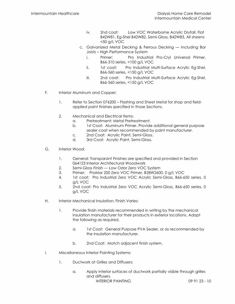
Intermountain Healthcare Dialysis Home Care Remodel
Intermountain Medical Center
INTERIOR PAINTING 09 91 23 - 10
iv. 2nd coat: Low VOC Waterborne Acrylic Dryfall, Flat
B42W81, Eg-Shel B42W82, Semi-Gloss, B42W83, All sheens
<50 g/L VOC
c. Galvanized Metal Decking & Ferrous Decking — Including Bar
Joists – High Performance System
i. Primer: Pro Industrial Pro-Cryl Universal Primer,
B66-310 series, <100 g/L VOC
ii. 1st coat: Pro Industrial Multi-Surface Acrylic Eg-Shel,
B66-560 series, <150 g/L VOC
iii. 2nd coat: Pro Industrial Multi-Surface Acrylic Eg-Shel,
B66-560 series, <150 g/L VOC
F. Interior Aluminum and Copper:
1. Refer to Section 076200 – Flashing and Sheet Metal for shop and field-
applied paint finishes specified in those Sections.
2. Mechanical and Electrical Items:
a. Pretreatment: Metal Pretreatment.
b. 1st Coat: Aluminum Primer. Provide additional general purpose
sealer coat when recommended by paint manufacturer.
c. 2nd Coat: Acrylic Paint, Semi-Gloss.
d. 3rd Coat: Acrylic Paint, Semi-Gloss.
G. Interior Wood:
1. General: Transparant Finishes are specified and provided in Section
064123 Interior Architectural Woodwork
2. Semi-Gloss Finish — Low Odor Zero VOC System
3. Primer: ProMar 200 Zero VOC Primer, B28W2600, 0 g/L VOC
4. 1st coat: Pro Industrial Zero VOC Acrylic Semi-Gloss, B66-650 series, 0
g/L VOC
5. 2nd coat: Pro Industrial Zero VOC Acrylic Semi-Gloss, B66-650 series, 0
g/L VOC
H. Interior Mechanical Insulation; Finish Varies:
1. Provide finish materials recommended in writing by the mechanical
insulation manufacturer for their products in exterior locations. Adapt
the following as required.
a. 1st Coat: General Purpose PVA Sealer, or as recommended by
the insulation manufacturer.
b. 2nd Coat: Match adjacent finish system.
I. Miscellaneous Interior Painting Systems:
1. Ductwork at Grilles and Diffusers:
a. Apply interior surfaces of ductwork partially visible through grilles
and diffusers.
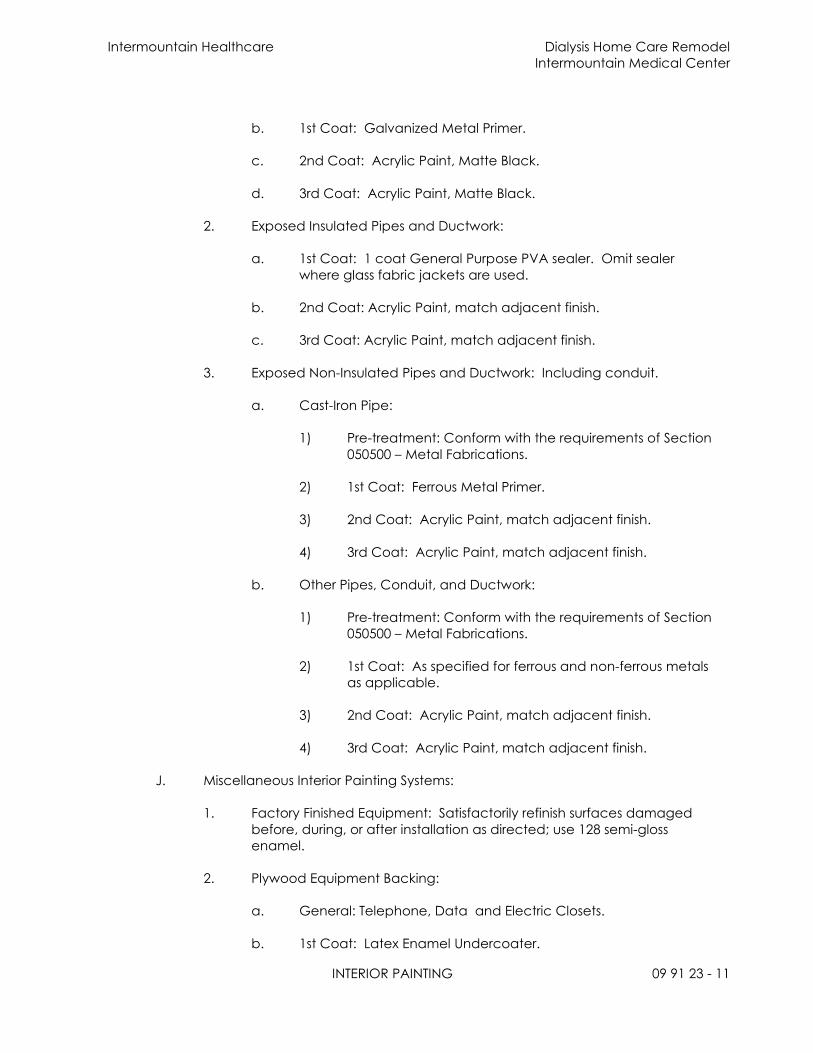
Intermountain Healthcare Dialysis Home Care Remodel
Intermountain Medical Center
INTERIOR PAINTING 09 91 23 - 11
b. 1st Coat: Galvanized Metal Primer.
c. 2nd Coat: Acrylic Paint, Matte Black.
d. 3rd Coat: Acrylic Paint, Matte Black.
2. Exposed Insulated Pipes and Ductwork:
a. 1st Coat: 1 coat General Purpose PVA sealer. Omit sealer
where glass fabric jackets are used.
b. 2nd Coat: Acrylic Paint, match adjacent finish.
c. 3rd Coat: Acrylic Paint, match adjacent finish.
3. Exposed Non-Insulated Pipes and Ductwork: Including conduit.
a. Cast-Iron Pipe:
1) Pre-treatment: Conform with the requirements of Section
050500 – Metal Fabrications.
2) 1st Coat: Ferrous Metal Primer.
3) 2nd Coat: Acrylic Paint, match adjacent finish.
4) 3rd Coat: Acrylic Paint, match adjacent finish.
b. Other Pipes, Conduit, and Ductwork:
1) Pre-treatment: Conform with the requirements of Section
050500 – Metal Fabrications.
2) 1st Coat: As specified for ferrous and non-ferrous metals
as applicable.
3) 2nd Coat: Acrylic Paint, match adjacent finish.
4) 3rd Coat: Acrylic Paint, match adjacent finish.
J. Miscellaneous Interior Painting Systems:
1. Factory Finished Equipment: Satisfactorily refinish surfaces damaged
before, during, or after installation as directed; use 128 semi-gloss
enamel.
2. Plywood Equipment Backing:
a. General: Telephone, Data and Electric Closets.
b. 1st Coat: Latex Enamel Undercoater.

Intermountain Healthcare Dialysis Home Care Remodel
Intermountain Medical Center
INTERIOR PAINTING 09 91 23 - 12
c. 2nd Coat: Acrylic Paint; match adjacent finish.
d. 3rd Coat: Acrylic Paint; match adjacent finish.
K. Pipe Identification:
1. General: Per ANSI A13.1; buried pipe, electrical conduit, and pipe in
concealed spaces such as furred spaces and shafts not included.
2. Color Scheme: ANSI Z53.1 in combination with legend and flow
markers; continuous total length coverage. Safety colors as specified
under applicable Mechanical Section.
3. Legend: Stencil letters of colors, type, and sizes per ANSI A13.1. Tags
for identification of pipes less than 3/4-inch overall outside diameter,
including valves and fittings; provided under applicable mechanical
Section.
4. Flow Markers: Provide each type with appropriate size arrows to
indicate flow direction in pipe; same color as legend.
5. Visibility: Locate legend and flowmarkers for easy visibility from
operating floor; space not over 20 feet with at least one per room.
L. STENCILING OF FIRE RATED AND SMOKE PARTITION WALLS:
A. Identify partitions indicated on drawings as having a required fire or
smoke rating.
1. Follow guidelines set in Chapter 7 of International Building Code or as
locally amended.
2. Permanently identify with stenciling
a. Mininum 6 inches high letters with minimum ½ inch stroke.
b. Bottom of lettering to start at 6 inches above ceiling.
c. Stenciling to be 10 feet on center max.
b. Color : Red for 1-hr rated walls, Blue for 2-hr rated walls, Green
for smoke partition walls.
c. Provide in a manner acceptable to authority having jurisdiction.
3.8 CLEANING:
A. Comply with provisions of Section 017900 – Cleaning.
B. Remove paint spots, oil, and stains from adjacent surfaces upon completion of
Work; leave Work clean.
END OF SECTION
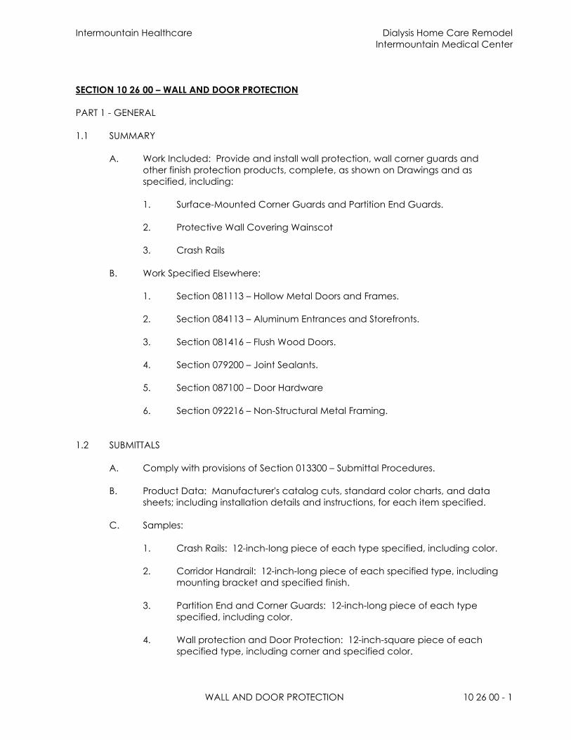
Intermountain Healthcare Dialysis Home Care Remodel
Intermountain Medical Center
WALL AND DOOR PROTECTION 10 26 00 - 1
SECTION 10 26 00 – WALL AND DOOR PROTECTION
PART 1 - GENERAL
1.1 SUMMARY
A. Work Included: Provide and install wall protection, wall corner guards and
other finish protection products, complete, as shown on Drawings and as
specified, including:
1. Surface-Mounted Corner Guards and Partition End Guards.
2. Protective Wall Covering Wainscot
3. Crash Rails
B. Work Specified Elsewhere:
1. Section 081113 – Hollow Metal Doors and Frames.
2. Section 084113 – Aluminum Entrances and Storefronts.
3. Section 081416 – Flush Wood Doors.
4. Section 079200 – Joint Sealants.
5. Section 087100 – Door Hardware
6. Section 092216 – Non-Structural Metal Framing.
1.2 SUBMITTALS
A. Comply with provisions of Section 013300 – Submittal Procedures.
B. Product Data: Manufacturer's catalog cuts, standard color charts, and data
sheets; including installation details and instructions, for each item specified.
C. Samples:
1. Crash Rails: 12-inch-long piece of each type specified, including color.
2. Corridor Handrail: 12-inch-long piece of each specified type, including
mounting bracket and specified finish.
3. Partition End and Corner Guards: 12-inch-long piece of each type
specified, including color.
4. Wall protection and Door Protection: 12-inch-square piece of each
specified type, including corner and specified color.

Intermountain Healthcare Dialysis Home Care Remodel
Intermountain Medical Center
WALL AND DOOR PROTECTION 10 26 00 - 2
1.3 PRODUCT HANDLING
A. Delivery and Storage: Deliver and store items and related fasteners in
manufacturer's original packaging, identified with manufacturer's name and
type of product, and size. Store materials indoors, protected from moisture
and other sources of damage.
PART 2 - PRODUCTS
2.1 MANUFACTURER
A. General: Provide vinyl/acrovyn wall and corner protection single-sourced from
one manufacturer to assure color matching.
B. Manufacturer: Inpro Corporation, Acrovyn Construction Specialties, Inc.,
Pawling Corporation OR Korogard
a. Basis-of-Design: Acrovyn wall protection systems
C. Fire Hazard Classification: Flame spread of 25 or less when tested per ASTM
E84.
2.3 CORNER GUARDS
A. Type: Acrovyn Surface mounted Corner Guard with continuous aluminum
retainer.
1. Size: 2” X 2” X 4’-0”.
2. Mounting Style: Surface-mounted.
3. Color: As scheduled on Drawings.
4. Mounting Height: 4” from top of finished floor. (match existing)
6. Locations: Typical at all corners and as shown on Drawings.
2.4 PROTECTIVE WALL COVERING WAINSCOT
A. Type: Sheet plastic wall protection by Acrovyn. Typical where shown on
Drawings.
1. Size: 0.060” thick Rigid Sheet by sizes shown on Drawings.
2. Mounting Style: Surface-mounted.
3. Extrusion: Extrusion: High-impact vinyl acrylic extrusion, nominal 078"
(1.98mm) thick. Class A fire rating, when tested
in accordance with ASTM E 84.
3. Color: As scheduled on Drawings.

Intermountain Healthcare Dialysis Home Care Remodel
Intermountain Medical Center
WALL AND DOOR PROTECTION 10 26 00 - 3
4. Mounting Height: From finished floor to 4 feet above finish floor. Align
top of wall protection with top of corner guards where occurs (Match
adjacent existing).
5. Locations: As shown on Drawings.
2.5 CRASH RAILS/ WALL GUARD
A. Manufacturer: Acrovyn (match adjacent existing)
B. Type: Acrovyn crash rail, surface-mounted crash rail with continuous aluminum
retainer. Typical at corridors and as shown on Drawings (match adjacent
existing).
1. Size: 8 inch tall by lengths shown on Drawings (match adjacent
existing)
2. Mounting Style: Surface Mounted
3. Color: As scheduled on Drawings.
4. Mounting Height: As shown on Drawings.
5. Locations: Typical at all corridor locations.
2.5 MISCELLANEOUS MATERIALS
A. Fasteners: Manufacturer's standard, removable, corrosion-resistant fasteners of
size and length suitable for the conditions of installation.
B. Adhesive: As recommended by manufacturer for setting material.
C. Backing Plates: As specified in Section 092216 – Non-Structural Metal Framing
and as shown on Drawings.
PART 3 - EXECUTION
3.1 EXAMINATION
A. Verification of Conditions: After application of wall base and finish painting of
walls is complete, examine areas and conditions under which items are to be
installed. If unsatisfactory conditions exist, do not proceed with the Work until
such conditions have been corrected.
3.2 PREPARATION
A. Cleaning: Prior to application, clean side of units that will be in contact with
wall surface.

Intermountain Healthcare Dialysis Home Care Remodel
Intermountain Medical Center
WALL AND DOOR PROTECTION 10 26 00 - 4
3.3 INSTALLATION
A. General: Install units per manufacturer's instructions and as specified. Install
wall and corner guards, crash rails and handrails plumb and true and securely
fastened to backing plates or substrates.
3.4 ADJUSTING AND CLEANING
A. Cleaning: Prior to time of final acceptance, strip units of protective coverings,
and clean in accordance with manufacturer's instructions.
B. Defective Materials: Remove and replace any defective, misaligned, or
damaged units, at no additional cost to Owner.
END OF SECTION
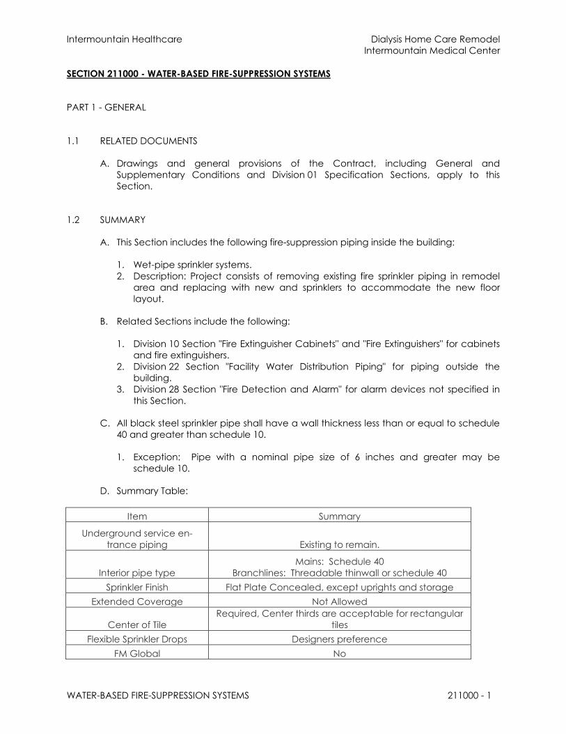
Intermountain Healthcare Dialysis Home Care Remodel
Intermountain Medical Center
WATER-BASED FIRE-SUPPRESSION SYSTEMS 211000 - 1
SECTION 211000 - WATER-BASED FIRE-SUPPRESSION SYSTEMS
PART 1 - GENERAL
1.1 RELATED DOCUMENTS
A. Drawings and general provisions of the Contract, including General and
Supplementary Conditions and Division 01 Specification Sections, apply to this
Section.
1.2 SUMMARY
A. This Section includes the following fire-suppression piping inside the building:
1. Wet-pipe sprinkler systems.
2. Description: Project consists of removing existing fire sprinkler piping in remodel
area and replacing with new and sprinklers to accommodate the new floor
layout.
B. Related Sections include the following:
1. Division 10 Section "Fire Extinguisher Cabinets" and "Fire Extinguishers" for cabinets
and fire extinguishers.
2. Division 22 Section "Facility Water Distribution Piping" for piping outside the
building.
3. Division 28 Section "Fire Detection and Alarm" for alarm devices not specified in
this Section.
C. All black steel sprinkler pipe shall have a wall thickness less than or equal to schedule
40 and greater than schedule 10.
1. Exception: Pipe with a nominal pipe size of 6 inches and greater may be
schedule 10.
D. Summary Table:
Item Summary
Underground service en-
trance piping Existing to remain.
Interior pipe type
Mains: Schedule 40
Branchlines: Threadable thinwall or schedule 40
Sprinkler Finish Flat Plate Concealed, except uprights and storage
Extended Coverage Not Allowed
Center of Tile
Required, Center thirds are acceptable for rectangular
tiles
Flexible Sprinkler Drops Designers preference
FM Global No

Intermountain Healthcare Dialysis Home Care Remodel
Intermountain Medical Center
WATER-BASED FIRE-SUPPRESSION SYSTEMS 211000 - 2
Calculations
Required. Contractor is responsible for obtaining flow
data for hydraulic calculations, use 10 percent reduced
flow data.
Alarm Device Existing to remain.
FDC Existing to remain.
Special Items
Seismic Use Ss = 0.821 g.
1.3 DEFINITIONS
A. CPVC: Chlorinated polyvinyl chloride plastic.
B. CR: Chlorosulfonated polyethylene synthetic rubber.
C. High-Pressure Piping System: Fire-suppression piping system designed to operate at
working pressure higher than standard 175 psig.
D. PE: Polyethylene plastic.
E. Underground Service-Entrance Piping: Underground service piping below the
building.
1.4 SYSTEM DESCRIPTIONS
A. Wet-Pipe Sprinkler System: Automatic sprinklers are attached to piping containing
water and that is connected to water supply. Water discharges immediately from
sprinklers when they are opened. Sprinklers open when heat melts fusible link or
destroys frangible device. Hose connections are included if indicated.
1.5 PERFORMANCE REQUIREMENTS
A. Standard Piping System Component Working Pressure: Listed for at least 175 psig.
B. High-Pressure Piping System Component Working Pressure: Listed for 250 psig
minimum 300 psig.
C. Fire-suppression standpipe system design shall be approved by authorities having
jurisdiction.
1. Minimum residual pressure at each hose-connection outlet is the following:
a. NPS 1-1/2 Hose Connections: 65 psig.
b. NPS 2-1/2 Hose Connections: 100 psig.
2. Unless otherwise indicated, the following is maximum residual pressure at required
flow at each hose-connection outlet:
a. NPS 1-1/2 Hose Connections: 100 psig.
b. NPS 2-1/2 Hose Connections: 175 psig.

Intermountain Healthcare Dialysis Home Care Remodel
Intermountain Medical Center
WATER-BASED FIRE-SUPPRESSION SYSTEMS 211000 - 3
D. Contractor is responsible for obtaining flow data for hydraulic calculations, use 10
percent reduced data. Design sprinkler piping according to 10 percent reduced flow
data and obtain approval from engineer, prior to submitting to other authorities
having jurisdiction:
1. Margin of Safety for Available Water Flow and Pressure: 10 percent, including
losses through water-service piping, valves, and backflow preventers.
2. Sprinkler Occupancy Hazard Classifications:
a. Automobile Parking Areas: Ordinary Hazard, Group 1.
b. Building Service Areas: Ordinary Hazard, Group 1.
c. Electrical Equipment Rooms: Ordinary Hazard, Group 1.
d. General Storage Areas: Ordinary Hazard, Group 1.
e. Laundries: Ordinary Hazard, Group 1.
f. Libraries, Except Stack Areas: Light Hazard.
g. Mechanical Equipment Rooms: Ordinary Hazard, Group 1.
h. Office and Public Areas: Light Hazard.
i. Residential Living Areas: Light Hazard.
j. Restaurant Service Areas: Ordinary Hazard, Group 1.
3. Minimum Density for Automatic-Sprinkler Piping Design:
a. Light-Hazard Occupancy: 0.10 gpm over 1500-sq. ft. area.
b. Ordinary-Hazard, Group 1 Occupancy: 0.15 gpm over 1500-sq. ft. area.
c. Ordinary-Hazard, Group 2 Occupancy: 0.20 gpm over 1500-sq. ft. area.
d. Special Occupancy Hazard: As determined by authorities having jurisdiction.
4. Minimum Density for Deluge-Sprinkler Piping Design:
a. Ordinary-Hazard, Group 1 Occupancy: 0.15 gpm over entire area.
b. Ordinary-Hazard, Group 2 Occupancy: 0.20 gpm over entire area.
c. Special Occupancy Hazard: As determined by authorities having jurisdiction.
5. Maximum Protection Area per Sprinkler: Per UL listing.
6. Maximum Protection Area per Sprinkler:
a. Office Spaces: 225 sq. ft..
b. Storage Areas: 130 sq. ft..
c. Mechanical Equipment Rooms: 130 sq. ft..
d. Electrical Equipment Rooms: 130 sq. ft..
e. Other Areas: According to NFPA 13 recommendations, unless otherwise
indicated.
7. Total Combined Hose-Stream Demand Requirement: According to NFPA 13,
unless otherwise indicated:
a. Light-Hazard Occupancies: 100 gpm for 30 minutes.
b. Ordinary-Hazard Occupancies: 250 gpm for 60 to 90 minutes.
8. Sprinklers are to be installed throughout the premises, as required by NFPA 13.
E. Seismic Performance: Fire-suppression piping shall be capable of withstanding the

Intermountain Healthcare Dialysis Home Care Remodel
Intermountain Medical Center
WATER-BASED FIRE-SUPPRESSION SYSTEMS 211000 - 4
effects of earthquake motions determined according to NFPA 13.
1.6 SUBMITTALS
A. Product Data: For the following:
1. Piping materials, including dielectric fittings, flexible connections, and sprinkler
specialty fittings.
2. Pipe hangers and supports, including seismic restraints.
3. Valves, including listed fire-protection valves, unlisted general-duty valves, and
specialty valves and trim.
4. Air compressors, including electrical data.
5. Sprinklers, escutcheons, and guards. Include sprinkler flow characteristics,
mounting, finish, and other pertinent data.
6. Hose connections, including size, type, and finish.
7. Fire department connections, including type; number, size, and arrangement of
inlets; caps and chains; size and direction of outlet; escutcheon and marking;
and finish.
8. Alarm devices, including electrical data.
B. Shop Drawings: Diagram power, signal, and control wiring.
C. Fire-hydrant flow test report.
D. Seismic Calculations.
E. Approved Sprinkler Piping Drawings: Working plans, prepared according to NFPA 13,
that have been approved by authorities having jurisdiction, including hydraulic
calculations, if applicable. Drawings are to be approved by Engineer prior to
submission to State Fire Marshal.
F. Field Test Reports and Certificates: Indicate and interpret test results for compliance
with performance requirements and as described in NFPA 13 and NFPA 14. Include
"Contractor's Material and Test Certificate for Aboveground Piping" and "Contractor's
Material and Test Certificate for Underground Piping."
G. Welding certificates.
H. Field quality-control test reports.
I. Operation and Maintenance Data: For standpipe and sprinkler specialties to include
in emergency, operation, and maintenance manuals.
1.7 QUALITY ASSURANCE
A. Installer Qualifications:
1. An experienced installer who has designed and installed fire-suppression piping
similar to that indicated for this Project and obtained design approval and
inspection approval from authorities having jurisdiction. The Engineer requires
evidence to support the ability of the contractor to perform work in the scope

Intermountain Healthcare Dialysis Home Care Remodel
Intermountain Medical Center
WATER-BASED FIRE-SUPPRESSION SYSTEMS 211000 - 5
and volume as specified. A contractor, who cannot show such experience, may
be found not suitable to perform the work. The following are the approved
contractors for this project:
a. PRE-APPROVED CONTRACTORS LIST
1) Alta Fire
2) Certified Fire
3) Chaparral Fire
4) Delta Fire
5) Kimco Fire
6) Preferred Fire Protection
7) Quality Fire Protection
8) Fire Services Inc.
9) FireTrol
10) FireFly Fire Protection
11) Simplex-Grinnell
12) State Fire DC Specialties
13) The Safety Team
14) Western Automatic
15) Or prior approved equal
b. A contractor not listed in the “PRE-APPROVED CONTRACTORS LIST” must
receive prior approval from the engineer to bid this project.
B. Installer's responsibilities include designing, fabricating, and installing fire-suppression
systems and providing professional engineering services needed to assume
engineering responsibility. Base calculations on results of fire-hydrant flow test.
1. Engineering Responsibility: Preparation of working plans, calculations, and field
test reports by a qualified professional engineer or NICET Level III technician.
C. Welding: Qualify processes and operators according to ASME Boiler and Pressure
Vessel Code: Section IX.
D. NFPA Standards: Fire-suppression-system equipment, specialties, accessories,
installation, and testing shall comply with the following:
1. NFPA 13, "Installation of Sprinkler Systems."
2. NFPA 13R, "Installation of Sprinkler Systems in Residential Occupancies up to and
Including Four Stories in Height."
3. NFPA 14, "Installation of Standpipe, Private Hydrant, and Hose Systems."
4. NFPA 24, "Installation of Private Fire Service Mains and Their Appurtenances."
E. International Conference of Building Code Officials codes and standards complying
with the following:
1. IBC-2015, “International Building Code.”
2. IFC-2015, “International Fire Code.”
F. Utah Amendments

Intermountain Healthcare Dialysis Home Care Remodel
Intermountain Medical Center
WATER-BASED FIRE-SUPPRESSION SYSTEMS 211000 - 6
1. Title 15A
1.8 COORDINATION
A. Coordinate layout and installation of sprinklers with other construction that
penetrates ceilings, including light fixtures, HVAC equipment, and partition
assemblies.
1.9 EXTRA MATERIALS
A. Furnish extra materials described below that match products installed and that are
packaged with protective covering for storage and identified with labels describing
contents.
1. Sprinkler Cabinets: Finished, wall-mounting, steel cabinet with hinged cover, with
space for minimum of six spare sprinklers plus sprinkler wrench. Include number of
sprinklers required by NFPA 13 and sprinkler wrench. Include separate cabinet
with sprinklers and wrench for each type of sprinkler on Project.
1.10 General Engineering Quality
A. Unless noted otherwise the following applies:
1. The maximum water velocity shall not exceed 32-fps.
2. Submit the calculations using the reduced flow data.
3. When calculating flexible drops, the contractor shall use the maximum number of
bends for the associated length. The value is to be taken from the UL tests (unless
the material is only FM approved).
4. In the event of multiple (3) submittal rejections (including revise and resubmit) a
meeting shall be held at the engineer’s office at the engineer time of choosing
and the designer, fire sprinkler contractor, and general contractor shall be
physically in attendance to discuss the required modifications to the design.
PART 2 - PRODUCTS
2.1 MANUFACTURERS
A. In other Part 2 articles where titles below introduce lists, the following requirements
apply to product selection:
1. Manufacturers: Subject to compliance with requirements, provide products by
one of the manufacturers specified.
2.2 DUCTILE-IRON PIPE AND FITTINGS
A. Mechanical-Joint, Ductile-Iron Pipe: AWWA C151, with mechanical-joint bell end
and plain end.

Intermountain Healthcare Dialysis Home Care Remodel
Intermountain Medical Center
WATER-BASED FIRE-SUPPRESSION SYSTEMS 211000 - 7
1. Mechanical-Joint, Ductile-Iron Fittings: AWWA C110, Class 53, ductile- or gray-iron
standard pattern or AWWA C153, ductile-iron compact pattern.
2. Glands, Gaskets, and Bolts: AWWA C111, ductile- or gray-iron gland, rubber
gasket, and steel bolts and nuts.
B. Push-on-Joint, Ductile-Iron Pipe: AWWA C151, with push-on-joint bell end and plain
end.
1. Push-on-Joint, Ductile-Iron Fittings: AWWA C110, ductile- or gray-iron standard
pattern or AWWA C153, ductile-iron compact pattern.
2. Gaskets: AWWA C111, rubber.
2.3 STAINLESS STEEL IN BUILDING RISER
A. Continuous from the factory, no field formed fittings in the stainless steel riser. Field
modifications are not allowed. Restrain with thrust block, per NFPA 24, rods as
required by manufacture.
1. Inlet: AWWA C900/DIP
2. Outlet: AWWA 606
2.4 STEEL PIPE AND FITTINGS
A. Threaded-End, Standard-Weight Steel Pipe: ASTM A 53/A 53M, ASTM A 135, or
ASTM A 795, hot-dip galvanized where indicated and with factory- or field-formed
threaded ends.
1. Cast-Iron Threaded Flanges: ASME B16.1.
2. Malleable-Iron Threaded Fittings: ASME B16.3.
3. Gray-Iron Threaded Fittings: ASME B16.4.
4. Steel Threaded Pipe Nipples: ASTM A 733, made of ASTM A 53/A 53M or
ASTM A 106, Schedule 40, seamless steel pipe hot-dip galvanized where
indicated. Include ends matching joining method.
5. Steel Threaded Couplings: ASTM A 865 hot-dip galvanized-steel pipe where
indicated.
B. Plain-End, Standard-Weight Steel Pipe: ASTM A 53/A 53M, ASTM A 135, or
ASTM A 795 hot-dip galvanized-steel pipe where indicated.
1. Locking-Lug Fittings: UL 213, ductile-iron body with retainer lugs that require one-
quarter turn to secure pipe in fitting not allowed.
C. Plain-End, Standard-Weight Steel Pipe: ASTM A 53/A 53M, ASTM A 135, or
ASTM A 795 hot-dip galvanized-steel pipe where indicated.
1. Steel Welding Fittings: ASTM A 234/A 234M, and ASME B16.9 or ASME B16.11.
2. Steel Flanges and Flanged Fittings: ASME B16.5.
D. Grooved-End, Standard-Weight Steel Pipe: ASTM A 53/A 53M, ASTM A 135, or
ASTM A 795, hot-dip galvanized where indicated and with factory- or field-formed,
roll-grooved ends.

Intermountain Healthcare Dialysis Home Care Remodel
Intermountain Medical Center
WATER-BASED FIRE-SUPPRESSION SYSTEMS 211000 - 8
1. Grooved-Joint Piping Systems:
a. Manufacturers:
1) Anvil International, Inc.
2) Central Sprinkler Corp.
3) Victaulic Co. of America.
4) Ward Manufacturing.
b. Grooved-End Fittings: UL-listed, ASTM A 536, ductile-iron casting with OD
matching steel-pipe OD.
c. Grooved-End-Pipe Couplings: UL 213 and AWWA C606, rigid pattern, unless
otherwise indicated; gasketed fitting matching steel-pipe OD. Include
ductile-iron housing with keys matching steel-pipe and fitting
grooves, prelubricated rubber gasket listed for use with housing, and steel
bolts and nuts.
E. Threaded-End, Threadable, Thinwall Steel Pipe: ASTM A 135 or ASTM A 795, with wall
thickness less than Schedule 40 and greater than Schedule 10, and with factory- or
field-formed threaded ends.
1. Cast-Iron Threaded Flanges: ASME B16.1.
2. Malleable-Iron Threaded Fittings: ASME B16.3.
3. Gray-Iron Threaded Fittings: ASME B16.4.
4. Steel Threaded Pipe Nipples: ASTM A 733, made of ASTM A 53/A 53M or
ASTM A 106, Schedule 40, seamless steel pipe.
5. Steel Threaded Couplings: ASTM A 865.
F. Plain-End, Threadable, Thinwall Steel Pipe: ASTM A 135 or ASTM A 795, with wall
thickness less than Schedule 40 and greater than Schedule 10.
1. Locking-Lug Fittings: UL 213, ductile-iron body with retainer lugs that require one-
quarter turn to secure pipe in fitting not allowed.
G. Plain-End, Threadable, Thinwall Steel Pipe: ASTM A 135 or ASTM A 795, with wall
thickness less than Schedule 40 and greater than Schedule 10.
1. Steel Welding Fittings: ASTM A 234/A 234M, and ASME B16.9 or ASME B16.11.
2. Steel Flanges and Flanged Fittings: ASME B16.5.
H. Grooved-End, Threadable, Thinwall Steel Pipe: ASTM A 135 or ASTM A 795, with wall
thickness less than Schedule 40 and greater than Schedule 10, and with factory- or
field-formed, roll-grooved ends.
1. Grooved-Joint Piping Systems:
a. Manufacturers:
1) Anvil International, Inc.
2) Central Sprinkler Corp.
3) Victaulic Co. of America.
4) Ward Manufacturing.

Intermountain Healthcare Dialysis Home Care Remodel
Intermountain Medical Center
WATER-BASED FIRE-SUPPRESSION SYSTEMS 211000 - 9
b. Grooved-End Fittings: UL-listed, ASTM A 536, ductile-iron casting with OD
matching steel-pipe OD.
c. Grooved-End-Pipe Couplings: UL 213 and AWWA C606, rigid pattern, unless
otherwise indicated; gasketed fitting matching steel-pipe OD. Include
ductile-iron housing with keys matching steel-pipe and fitting
grooves, prelubricated rubber gasket listed for use with housing, and steel
bolts and nuts.
I. Plain-End, Schedule 10 Steel Pipe: ASTM A 135 or ASTM A 795, Schedule 10 is not
allowed.
J. Plain-End, Nonstandard OD, Thinwall Steel Pipe: ASTM A 135 or ASTM A 795, with wall
thickness less than Schedule 10 is not allowed.
K. Plain-End, Hybrid Steel Pipe: ASTM A 135 or ASTM A 795, lightwall, with wall thickness
less than Schedule 10 and greater than Schedule 5 is not allowed.
L. Grooved-End, Hybrid Steel Pipe: ASTM A 135 or ASTM A 795, lightwall, with wall
thickness less than Schedule 10 and greater than Schedule 5; with factory- or field-
formed, roll-grooved ends are not allowed.
M. Schedule 5 Steel Pipe: ASTM A 135 or ASTM A 795, lightwall, with plain ends is not
allowed.
2.5 COPPER TUBE AND FITTINGS
A. Soft Copper Tube: ASTM B 88, Type L, water tube, annealed temper; with plain ends.
1. Copper fittings: ASME B16.18, cast-copper-alloy or ASME B16.22, wrought-copper,
solder-joint pressure type. Furnish only wrought-copper fittings if indicated.
2. Brazing Filler Metals: AWS A5.8, BCuP-3 or BCuP-4.
B. Plain-End, Hard Copper Tube: ASTM B 88, Type K or ASTM B 88, Type L, water tube,
drawn temper.
1. Copper Fittings: ASME B16.18, cast-copper-alloy or ASME B16.22, wrought-
copper, solder-joint pressure type. Furnish only wrought-copper fittings if
indicated.
2. Bronze Flanges: ASME B16.24, Class 150, with solder-joint end. Furnish Class 300
flanges if required to match tubing system.
3. Copper Unions: MSS SP-123, cast-copper-alloy, hexagonal-stock body with ball-
and-socket metal-to-metal seating surfaces, and solder-joint or threaded ends.
4. Copper, Mechanically Formed Tee Option: For forming T-branch on copper
water tube not allowed.
5. Brazing Filler Metals: AWS A5.8, BCuP-3 or BCuP-4.
C. Grooved-End, Hard Copper Tube: ASTM B 88, Type K or ASTM B 88, Type L, water
tube, drawn temper; with factory- or field-formed, roll-grooved ends.
1. Copper, Mechanically Formed Tee Option: For forming T-branch on copper
water tube not allowed.
2. Grooved-Joint Systems:

Intermountain Healthcare Dialysis Home Care Remodel
Intermountain Medical Center
WATER-BASED FIRE-SUPPRESSION SYSTEMS 211000 - 10
a. Manufacturers:
1) Anvil International, Inc.
2) Victaulic Co. of America.
b. Grooved-End Copper Fittings: ASTM B 75, copper tube or ASTM B 584, bronze
casting. Fittings may have ends factory or field expanded to steel-pipe OD if
required for copper tube systems using grooved-end-pipe couplings.
c. Grooved-End-Tube Couplings: UL 213, rigid pattern, unless otherwise
indicated; gasketed fitting equivalent to AWWA C606, but made to match
copper-tube OD. Include ductile-iron housing with keys matching steel-pipe
and fitting grooves, prelubricated rubber gasket listed for use with housing,
and steel bolts and nuts. Use grooved-end-pipe couplings for tube and fitting
that have expanded ends.
2.6 DIELECTRIC FITTINGS
A. Assembly shall be copper alloy, ferrous, and insulating materials with ends matching
piping system.
B. Dielectric Unions: Factory-fabricated assembly, designed for 250-psig minimum
working pressure at 180 deg F. Include insulating material that isolates dissimilar
materials and ends with inside threads according to ASME B1.20.1.
1. Manufacturers:
a. Capitol Manufacturing Co.
b. Central Plastics Company.
c. Epco Sales, Inc.
d. Hart Industries International, Inc.
e. Watts Industries, Inc.; Water Products Div.
f. Zurn Industries, Inc.; Wilkins Div.
C. Dielectric Flanges: Factory-fabricated companion-flange assembly, for 175-psig
minimum working-pressure rating as required for piping system.
1. Manufacturers:
a. Capitol Manufacturing Co.
b. Central Plastics Company.
c. Epco Sales, Inc.
d. Watts Industries, Inc.; Water Products Div.
D. Dielectric Flange Insulation Kits: Components for field assembly shall include CR or
phenolic gasket, PE or phenolic bolt sleeves, phenolic washers, and steel backing
washers.
1. Manufacturers:
a. Advance Products and Systems, Inc.
b. Calpico, Inc.
c. Central Plastics Company.

Intermountain Healthcare Dialysis Home Care Remodel
Intermountain Medical Center
WATER-BASED FIRE-SUPPRESSION SYSTEMS 211000 - 11
d. Pipeline Seal and Insulator, Inc.
e. Insert manufacturer's name.
E. Dielectric Couplings: Galvanized steel with inert and noncorrosive thermoplastic
lining and threaded ends and 300-psig working-pressure rating at 225 deg F.
1. Manufacturers:
a. Calpico, Inc.
b. Lochinvar Corp.
F. Dielectric Nipples: Electroplated steel with inert and noncorrosive thermoplastic
lining, with combination of plain, threaded, or grooved ends and 300-psig working-
pressure rating at 225 deg F.
1. Manufacturers:
a. Perfection Corporation.
b. Precision Plumbing Products, Inc.
c. Victaulic Co. of America.
2.7 FLEXIBLE SPRINKLER DROPS
A. Flexible connectors shall be FM approved with exterior wire braid and have materials
suitable for system fluid. Include 175-psig minimum working-pressure rating and ends
according to the following:
1. NPS 1: Threaded.
B. Manufacturers:
1. Flex-Head
2. Victaulic
C. Stainless-Steel-Hose/Steel Pipe, Flexible Connectors: Corrugated, stainless-steel, inner
tubing covered with stainless-steel wire braid. Include steel nipples or flanges,
welded to hose.
D. Stainless-Steel-Hose/Stainless-Steel Pipe, Flexible Connectors: Corrugated, stainless-
steel, inner tubing covered with stainless-steel wire braid. Include stainless-steel
nipples or flanges, welded to hose.
2.8 FLEXIBLE PIPE CONNECTORS (SEISMIC)
A. Flexible connectors shall be FM approved with exterior wire braid and have materials
suitable for system fluid. Include 175-psig minimum working-pressure rating and ends
according to the following:
1. NPS 2 and Smaller: Threaded.
2. NPS 2-1/2 and Larger: Flanged.
3. Option for NPS 2-1/2 and Larger: Grooved for use with grooved-end-pipe

Intermountain Healthcare Dialysis Home Care Remodel
Intermountain Medical Center
WATER-BASED FIRE-SUPPRESSION SYSTEMS 211000 - 12
couplings.
B. Manufacturers:
1. Flexicraft Industries.
2. Flex-Pression, Ltd.
3. Metraflex, Inc.
C. Bronze-Hose, Flexible Connectors: Corrugated, bronze, inner tubing covered with
bronze wire braid. Include copper-tube ends or bronze flanged ends, braze welded
to hose.
D. Stainless-Steel-Hose/Steel Pipe, Flexible Connectors: Corrugated, stainless-steel, inner
tubing covered with stainless-steel wire braid. Include steel nipples or flanges,
welded to hose.
E. Stainless-Steel-Hose/Stainless-Steel Pipe, Flexible Connectors: Corrugated, stainless-
steel, inner tubing covered with stainless-steel wire braid. Include stainless-steel
nipples or flanges, welded to hose.
2.9 CORROSION-PROTECTIVE ENCASEMENT FOR PIPING
A. Encasement for Underground Metal Piping: ASTM A 674 or AWWA C105, PE film, 0.008-
inch minimum thickness, tube or sheet.
2.10 SPRINKLER SPECIALTY FITTINGS
A. Sprinkler specialty fittings shall be FMG approved with 175-psig minimum working-
pressure rating, and made of materials compatible with piping. Sprinkler specialty
fittings shall have 250-psig minimum working-pressure rating if fittings are components of
high-pressure piping systems.
B. Sprinkler Drain and Alarm Test Fittings: Cast- or ductile-iron body, with threaded or
locking-lug inlet and outlet, test valve, and orifice and sight glass.
1. Manufactures:
a. Central Sprinkler Corp.
b. Fire-End and Croker Corp.
c. Viking Corp.
d. Victaulic Co. of America.
C. Sprinkler Branch-Line Test Fittings: Brass body with threaded inlet, capped drain outlet,
and threaded outlet for sprinkler.
D. Sprinkler Inspector’s Test Fitting: Cast- or ductile-iron housing with threaded inlet and
drain outlet and sight glass.
E. Drop-Nipple Fittings: UL 1474, adjustable with threaded inlet and outlet, and seals.

Intermountain Healthcare Dialysis Home Care Remodel
Intermountain Medical Center
WATER-BASED FIRE-SUPPRESSION SYSTEMS 211000 - 13
F. Dry-Pipe-System Fittings: UL listed for dry-pipe service.
2.11 LISTED FIRE-PROTECTION VALVES
A. Valves shall be FMG approved, with 175-psig minimum pressure rating. Valves shall
have 250-psig minimum pressure rating if valves are components of high-pressure
piping system.
B. Gate Valves with Wall Indicator Posts:
1. Gate Valves: UL 262, cast-iron body, bronze mounted, with solid disc, nonrising
stem, operating nut, and flanged ends.
2. Indicator Posts: UL 789, horizontal-wall type, cast-iron body, with hand wheel,
extension rod, locking device, and cast-iron barrel.
3. Manufacturers:
a. Grinnell Fire Protection.
b. McWane, Inc.; Kennedy Valve Div.
c. NIBCO.
d. Stockham.
C. Ball Valves: Comply with UL 1091, except with ball instead of disc.
1. NPS 1-1/2 and Smaller: Bronze body with threaded ends.
2. NPS 2 and NPS 2-1/2: Bronze body with threaded ends or ductile-iron body with
grooved ends.
3. NPS 3: Ductile-iron body with grooved ends.
4. Manufacturers:
a. NIBCO.
b. Victaulic Co. of America.
D. Butterfly Valves: UL 1091.
1. NPS 2 and Smaller: Bronze body with threaded ends.
a. Manufacturers:
1) Global Safety Products, Inc.
2) Milwaukee Valve Company.
2. NPS 2-1/2 and Larger: Bronze, cast-iron, or ductile-iron body; wafer type or with
flanged or grooved ends.
a. Manufacturers:
1) Central Sprinkler Corp.
2) McWane, Inc.; Kennedy Valve Div.
3) Mueller Company.
4) NIBCO.
5) Victaulic Co. of America.

Intermountain Healthcare Dialysis Home Care Remodel
Intermountain Medical Center
WATER-BASED FIRE-SUPPRESSION SYSTEMS 211000 - 14
E. Check Valves NPS 2 and Larger: UL 312, swing type, cast-iron body with flanged or
grooved ends.
1. Manufacturers:
a. American Cast Iron Pipe Co.; Waterous Co.
b. Central Sprinkler Corp.
c. Clow Valve Co.
d. Crane Co.; Crane Valve Group; Crane Valves.
e. Crane Co.; Crane Valve Group; Jenkins Valves.
f. Fivalco
g. Globe Fire Sprinkler Corporation.
h. Grinnell Fire Protection.
i. Hammond Valve.
j. McWane, Inc.; Kennedy Valve Div.
k. Mueller Company.
l. NIBCO.
m. Potter-Roemer; Fire Protection Div.
n. Reliable Automatic Sprinkler Co., Inc.
o. Star Sprinkler Inc.
p. Stockham.
q. United Brass Works, Inc.
r. Victaulic Co. of America.
s. Watts Industries, Inc.; Water Products Div.
F. Gate Valves: UL 262, OS&Y type.
1. NPS 2 and Smaller: Bronze body with threaded ends.
a. Manufacturers:
1) Crane Co.; Crane Valve Group; Crane Valves.
2) Fivalco.
3) Hammond Valve.
4) NIBCO.
5) United Brass Works, Inc.
2. NPS 2-1/2 and Larger: Cast-iron body with flanged ends.
a. Manufacturers:
1) Clow Valve Co.
2) Crane Co.; Crane Valve Group; Crane Valves.
3) Crane Co.; Crane Valve Group; Jenkins Valves.
4) Fivalco
5) Hammond Valve.
6) Milwaukee Valve Company.
7) Mueller Company.
8) NIBCO.
9) United Brass Works, Inc.
G. Indicating Valves: UL 1091, with integral indicating device and ends matching

Intermountain Healthcare Dialysis Home Care Remodel
Intermountain Medical Center
WATER-BASED FIRE-SUPPRESSION SYSTEMS 211000 - 15
connecting piping.
1. Indicator: Electrical, 115-V ac, prewired, single-circuit, supervisory switch and
Visual.
2. NPS 2 and Smaller: Ball or butterfly valve with bronze body and threaded ends.
a. Manufacturers:
1) Milwaukee Valve Company.
2) NIBCO.
3) Victaulic Co. of America.
3. NPS 2-1/2 and Larger: Butterfly valve with cast- or ductile-iron body; wafer type or
with flanged or grooved ends.
a. Manufacturers:
1) Central Sprinkler Corp.
2) Grinnell Fire Protection.
3) McWane, Inc.; Kennedy Valve Div.
4) Milwaukee Valve Company.
5) NIBCO.
6) Victaulic Co. of America.
H. Supervised Normally Closed Valve
1. Indicator: Electrical, 115-V ac, prewired, single-circuit, supervisory switch and
visual to send signal on partial close.
a. Manufactures:
1) NIBCO.
2) Victaulic Co. of America.
2.12 UNLISTED GENERAL-DUTY VALVES
A. Ball Valves NPS 2 and Smaller: MSS SP-110, 2-piece copper-alloy body with chrome-
plated brass ball, 600-psig minimum CWP rating, blowout-proof stem, and threaded
ends.
B. Check Valves NPS 2 and Smaller: MSS SP-80, Type 4, Class 125 minimum, swing type
with bronze body, nonmetallic disc, and threaded ends.
C. Gate Valves NPS 2 and Smaller: MSS SP-80, Type 2, Class 125 minimum, with bronze
body, solid wedge, and threaded ends.
D. Globe Valves NPS 2 and Smaller: MSS SP-80, Type 2, Class 125 minimum, with bronze
body, nonmetallic disc, and threaded ends.
2.13 SPECIALTY VALVES

Intermountain Healthcare Dialysis Home Care Remodel
Intermountain Medical Center
WATER-BASED FIRE-SUPPRESSION SYSTEMS 211000 - 16
A. Sprinkler System Control Valves: FMG approved, cast- or ductile-iron body with
flanged or grooved ends, and 175-psig minimum pressure rating. Control valves shall
have 250-psig minimum pressure rating if valves are components of high-pressure
piping system.
1. Manufacturers:
a. Globe Fire Sprinkler Corporation.
b. Reliable Automatic Sprinkler Co., Inc.
c. Victaulic Co. of America.
d. Viking Corp.
2. Dry-Pipe Valves: UL 260, differential type; with bronze seat with O-ring seals,
single-hinge pin, and latch design. Include UL 1486, quick-opening devices, trim
sets for air supply, drain, priming level, alarm connections, ball drip valves,
pressure gages, priming chamber attachment, and fill-line attachment.
a. Air-Pressure Maintenance Device: UL 260, automatic device to maintain
correct air pressure in piping. Include shutoff valves to permit servicing
without shutting down sprinkler piping, bypass valve for quick filling, pressure
regulator or switch to maintain pressure, strainer, pressure ratings with 14- to
60-psig adjustable range, and 175-psig maximum inlet pressure.
1) Manufacturers:
a) AFAC Inc.
b) Central Sprinkler Corp.
c) General Air Products, Inc.
d) Globe Fire Sprinkler Corporation.
e) Reliable Automatic Sprinkler Co., Inc.
f) Viking Corp.
b. Air Compressor: UL 753, fractional horsepower, 120-V ac, 60 Hz, single phase.
1) Manufacturers:
a) AFAC Inc.
b) Gast Manufacturing, Inc.
c) General Air Products, Inc.
d) Grinnell Fire Protection.
e) Reliable Automatic Sprinkler Co., Inc.
f) Viking Corp.
3. Deluge Valves: UL 260, cast-iron body, hydraulically operated, differential-
pressure type. Include bronze seat with O-ring seals, trim sets for bypass, drain,
electrical sprinkler alarm switch, pressure gages, drip cup assembly piped without
valves and separate from main drain line, fill-line attachment with strainer, and
push-rod chamber supply connection.
a. Dry, Pilot-Line Trim Set: Include dry, pilot-line actuator; air- and water-
pressure gages; low-air-pressure warning switch; air relief valve; and
actuation device. Dry, pilot-line actuator includes cast-iron, operated,
Intermountain Healthcare Dialysis Home Care Remodel
Intermountain Medical Center
WATER-BASED FIRE-SUPPRESSION SYSTEMS 211000 - 17
diaphragm-type valve with resilient facing plate, resilient diaphragm, and
replaceable bronze seat. Valve includes threaded water and air inlets and
water outlet. Loss of air pressure on dry, pilot-line side allows pilot-line
actuator to open and causes deluge valve to open immediately.
B. Automatic Drain Valves: UL 1726, NPS 3/4, ball-check device with threaded ends.
1. Manufacturers:
a. Grinnell Fire Protection.
2.14 SPRINKLERS
A. Sprinklers shall be UL listed or FMG approved, with 175-psig minimum pressure rating.
Sprinklers shall have 250-psig minimum 300-psig pressure rating if sprinklers are
components of high-pressure piping system.
B. Sprinklers shall have 250-psig minimum 300-psig pressure rating if sprinklers are
components of high-pressure piping system.
C. Manufacturers:
1. Globe Fire Sprinkler Corporation.
2. Reliable Automatic Sprinkler Co., Inc.
3. Victaulic Co. of America.
4. Viking Corp.
5. Tyco Fire
D. Automatic Sprinklers: With heat-responsive element complying with the following:
1. UL 199, for nonresidential applications.
2. UL 1626, for residential applications.
E. Sprinkler Types and Categories: Nominal 1/2-inch orifice for "Ordinary" temperature
classification rating, unless otherwise indicated or required by application.
1. Open Sprinklers: UL 199, without heat-responsive element.
a. Orifice: 1/2 inch, with discharge coefficient K between 5.3 and 5.8.
b. Orifice: 17/32 inch, with discharge coefficient K between 7.4 and 8.2.
F. Sprinkler types, features, and options as follows:
1. Concealed ceiling sprinklers, including cover plate.
2. Extended-coverage sprinklers, not allowed unless approved in writing prior to
bidding.
3. Flow-control sprinklers, with automatic open and shutoff feature.
4. Flush ceiling sprinklers, including escutcheon, not allowed.
5. Institution sprinklers, made with a small, breakaway projection.
6. Pendent sprinklers.
7. Pendent, dry-type sprinklers.
8. Quick-response sprinklers.

Intermountain Healthcare Dialysis Home Care Remodel
Intermountain Medical Center
WATER-BASED FIRE-SUPPRESSION SYSTEMS 211000 - 18
9. Recessed sprinklers, including escutcheon.
10. Sidewall sprinklers.
11. Sidewall, dry-type sprinklers.
12. Upright sprinklers.
G. Sprinkler Finishes: Chrome plated, bronze, and painted. Finishes as approved by FM
Global.
H. Special Coatings: Wax, lead, and corrosion-resistant paint.
I. Sprinkler Escutcheons: Materials, types, and finishes for the following sprinkler
mounting applications. Escutcheons for concealed, flush, and recessed-type
sprinklers are specified with sprinklers.
1. Ceiling Mounting: Flat plate concealed, white.
2. Sidewall Mounting: Semi-Recessed, white.
J. Sprinkler Guards: Wire-cage type, including fastening device for attaching to
sprinkler.
2.15 HOSE CONNECTIONS
A. Manufacturers:
1. Central Sprinkler Corp.
2. Elkhart Brass Mfg. Co., Inc.
3. Fire-End and Croker Corp.
4. Fivalco
5. Grinnell Fire Protection.
6. Guardian Fire Equipment Incorporated.
7. McWane, Inc.; Kennedy Valve Div.
8. Mueller Company.
9. Potter-Roemer; Fire-Protection Div.
10. United Brass Works, Inc.
B. Description: UL 668, brass or bronze, 300-psig minimum pressure rating, hose valve for
connecting fire hose. Include angle or gate pattern design; female NPS inlet and
male hose outlet; and lugged cap, gasket, and chain. Include NPS 1-1/2 or NPS 2-
1/2, and hose valve threads according to NFPA 1963 and matching local fire
department threads.
1. Valve Operation: Nonadjustable type, unless pressure-regulating type is
indicated.
2. Finish: Rough metal.
2.16 FIRE DEPARTMENT CONNECTIONS
A. Manufacturers:
1. Central Sprinkler Corp.
2. Elkhart Brass Mfg. Co., Inc.

Intermountain Healthcare Dialysis Home Care Remodel
Intermountain Medical Center
WATER-BASED FIRE-SUPPRESSION SYSTEMS 211000 - 19
3. Fire-End and Croker Corp.
4. Fire Protection Products, Inc.
5. Guardian Fire Equipment Incorporated.
6. Potter-Roemer; Fire-Protection Div.
7. Reliable Automatic Sprinkler Co., Inc.
8. United Brass Works, Inc.
B. Wall-Type, Fire Department Connection: UL 405, 175-psig minimum pressure rating;
with corrosion-resistant-metal body with brass inlets, brass wall escutcheon plate,
brass lugged caps with gaskets and brass chains, and brass lugged swivel
connections. Include inlets with threads according to NFPA 1963 and matching local
fire department sizes and threads, outlet with pipe threads, extension pipe nipples,
check devices or clappers for inlets, and escutcheon plate with marking similar to
"AUTO SPKR & STANDPIPE."
1. Type: Existing to remain.
2.17 ALARM DEVICES
A. Alarm-device types shall match piping and equipment connections.
B. Electrically Operated Alarm: UL 464, with 8-inch- minimum- diameter, vibrating-type,
metal alarm bell with red-enamel factory finish and suitable for outdoor use.
1. Manufacturers:
a. Potter Electric Signal Company.
b. System Sensor.
C. Electrically Operated Alarm: Horn/Strobe, NEMA 3R minimum suitable for outdoor
use.
1. Manufacturers:
a. Potter Electric Signal Company.
b. System Sensor.
D. Water-Flow Indicator: UL 346, electrical-supervision, paddle-operated-type, water-
flow detector with 250-psig pressure rating and designed for horizontal or vertical
installation. Include two single-pole, double-throw circuit switches for isolated alarm
and auxiliary contacts, 7 A, 125-V ac and 0.25 A, 24-V dc; complete with factory-set,
field-adjustable retard element to prevent false signals and tamperproof cover that
sends signal if removed.
1. Manufacturers:
a. ADT Security Services, Inc.
b. Grinnell Fire Protection.
c. ITT McDonnell & Miller.
d. Potter Electric Signal Company.
e. System Sensor.
f. Viking Corp.

Intermountain Healthcare Dialysis Home Care Remodel
Intermountain Medical Center
WATER-BASED FIRE-SUPPRESSION SYSTEMS 211000 - 20
g. Watts Industries, Inc.; Water Products Div.
E. Pressure Switch: UL 753, electrical-supervision-type, water-flow switch with retard
feature. Include single-pole, double-throw, normally closed contacts and design that
operates on rising pressure and signals water flow.
1. Manufacturers:
a. Grinnell Fire Protection.
b. Potter Electric Signal Company.
c. System Sensor.
d. Viking Corp.
F. Valve Supervisory Switch: UL 753, electrical, single-pole, double-throw switch with
normally closed contacts. Include design that signals controlled valve is in other than
fully open position.
1. Manufacturers:
a. McWane, Inc.; Kennedy Valve Div.
b. Potter Electric Signal Company.
c. System Sensor.
G. Indicator-Post Supervisory Switch: UL 753, electrical, single-pole, double-throw switch
with normally closed contacts. Include design that signals controlled indicator-post
valve is in other than fully open position.
1. Manufacturers:
a. Potter Electric Signal Company.
b. System Sensor.
2.18 PRESSURE GAGES
A. Manufacturers:
1. Brecco Corporation.
2. Dresser Equipment Group; Instrument Div.
3. Marsh Bellofram.
4. WIKA Instrument Corporation.
B. Description: UL 393, 3-1/2- to 4-1/2-inch- diameter, dial pressure gage with range of 0
to 250 psig minimum.
1. Water System Piping: Include caption "WATER" or "AIR/WATER" on dial face.
2. Air System Piping: Include retard feature and caption "AIR" or "AIR/WATER" on dial
face.
2.19 DOUBLE CHECK VALVE ASSEMBLIES
A. Manufacturers

Intermountain Healthcare Dialysis Home Care Remodel
Intermountain Medical Center
WATER-BASED FIRE-SUPPRESSION SYSTEMS 211000 - 21
1. Ames
2. Backflow Direct
3. Febco
4. Wilkins
5. Watts
B. Description; Resilient seated, spring loaded with testable outlets provided, as required
by Authorities Having Jurisdiction.
PART 3 - EXECUTION
3.1 PREPARATION
A. Obtain Engineer’s Water Analysis or fire-hydrant flow test. Use results for system
design calculations required in "Quality Assurance" Article in Part 1 of this Section.
B. Engineer’s Water Analysis. See Flow Analysis provided by Van Boerum & Frank
Associates.
3.2 EARTHWORK
A. Refer to Division 31 Section "Earth Moving" for excavating, trenching, and backfilling.
3.3 EXAMINATION
A. Examine roughing-in for hose connections and stations to verify actual locations of
piping connections before installation.
B. Examine walls and partitions for suitable thicknesses, fire- and smoke-rated
construction, framing for hose-station cabinets, and other conditions where hose
connections and stations are to be installed.
C. Proceed with installation only after unsatisfactory conditions have been corrected.
3.4 PIPING APPLICATIONS
A. Shop weld pipe joints where welded piping is indicated.
B. Do not use welded joints for galvanized-steel pipe.
C. Flanges, flanged fittings, unions, nipples, and transition and special fittings with finish
and pressure ratings same as or higher than system's pressure rating may be used in
aboveground applications, unless otherwise indicated.
D. Piping between Fire Department Connections and Check Valves: Galvanized,
standard-weight steel pipe with grooved ends; grooved-end fittings; grooved-end-
pipe couplings; and grooved joints.

Intermountain Healthcare Dialysis Home Care Remodel
Intermountain Medical Center
WATER-BASED FIRE-SUPPRESSION SYSTEMS 211000 - 22
E. Underground Service-Entrance Piping: Ductile-iron, push-on or mechanical-joint pipe
and fittings and restrained joints. Include corrosion-protective encasement.
F. Sprinkler Main Piping: Use the following:
1. NPS 6 and Smaller: Standard-weight steel pipe with threaded ends, or grooved
ends. No plain ends allowed.
2. Outlets shall be welded.
a. Victaulic Brand Mechanical tee fittings may be used in lieu of welded
outlets.
G. Branch line piping: Use the following:
1. NPS 2 and Smaller: Threadable steel pipe with threaded ends; cast- or malleable-
iron threaded fittings; and threaded joints.
a. Victaulic Brand Mechanical tee fittings may be used
H. Standpipes and mains: Use the following:
1. NPS 4 to NPS 6: Schedule 40 steel pipe with grooved ends & Welded outlets.
2. NPS 3 and Smaller: Schedule 40 steel pipe with threaded ends, or grooved ends.
No plain ends allowed.
3.5 VALVE APPLICATIONS
A. Drawings indicate valve types to be used. Where specific valve types are not
indicated, the following requirements apply:
1. Fire-Protection-Service Valves: UL listed and FM approved for applications where
required by NFPA 13 and NFPA 14.
2. General-Duty Valves: For applications where UL-listed and FM-approved valves
are not required by NFPA 13 and NFPA 14.
a. Shutoff Duty: Use gate, ball, or butterfly valves.
b. Throttling Duty: Use globe, ball, or butterfly valves.
3.6 JOINT CONSTRUCTION
A. Refer to Division 23 Section "Common Work Result for HVAC" for basic piping joint
construction.
B. Ductile-Iron-Piping, Grooved Joints: Use ductile-iron pipe with radius-cut-grooved
ends; ductile-iron, grooved-end fittings; and ductile-iron, keyed couplings. Assemble
joints with couplings, gaskets, lubricant, and bolts according to coupling
manufacturer's written instructions.
C. Steel-Piping, Grooved Joints: Use Schedule 40 steel pipe with cut or roll-grooved ends
and Schedule 30 or thinner steel pipe with roll-grooved ends; steel, grooved-end

Intermountain Healthcare Dialysis Home Care Remodel
Intermountain Medical Center
WATER-BASED FIRE-SUPPRESSION SYSTEMS 211000 - 23
fittings; and steel, keyed couplings. Assemble joints with couplings, gaskets, lubricant,
and bolts according to coupling manufacturer's written instructions. Use gaskets
listed for dry-pipe service for dry piping.
3.7 WATER-SUPPLY CONNECTION
A. Install shutoff Backflow preventions assemblies, valve, pressure gage’s, drain, and
other accessories at connection to water service.
3.8 PIPING INSTALLATION
A. Refer to Division 23 Section "Common Work Result for HVAC" for basic piping
installation.
B. Locations and Arrangements: Drawing plans, schematics, and diagrams indicate
general location and arrangement of piping. Install piping as indicated, as far as
practical.
1. Deviations from approved working plans for piping require written approval from
authorities having jurisdiction. File written approval with Architect before
deviating from approved working plans.
C. Install underground service-entrance piping according to NFPA 24 and with
restrained joints.
D. Make connections between underground and above-ground piping using bolted
flange.
E. Install mechanical sleeve seal at pipe penetrations in basement and foundation
walls. Refer to Division 23 Section “Common Work Result for HVAC.”
F. Use approved fittings to make changes in direction, branch takeoffs from mains, and
reductions in pipe sizes.
G. Install unions adjacent to each valve in pipes NPS 2 and smaller. Unions are not
required on flanged devices or in piping installations using grooved joints.
H. Install flanges or flange adapters on valves, apparatus, and equipment having NPS 2-
1/2 and larger connections.
I. Install "Inspector's Test Connections" in sprinkler piping, complete with shutoff valve,
sized and located according to NFPA 13.
J. Install sprinkler piping with drains for complete system drainage.
K. Install sprinkler zone control valves, check valves, test assemblies, and drain risers
adjacent to standpipes when sprinkler piping is connected to standpipes.
L. Install drain valves on standpipes.
M. Install ball drip valves to drain piping between fire department connections and
Intermountain Healthcare Dialysis Home Care Remodel
Intermountain Medical Center
WATER-BASED FIRE-SUPPRESSION SYSTEMS 211000 - 24
check valves. Drain to floor drain or outside building.
N. Install alarm devices in piping systems.
O. Hangers and Supports: Comply with NFPA 13 for hanger materials. Install according
to NFPA 13 for sprinkler piping and to NFPA 14 for standpipes.
1. No powder driven studs allowed.
2. Wrap-around braces are to be provided at end of branch lines.
P. Earthquake Protection: Install piping according to NFPA 13-9.3 requirements, to
protect from earthquake damage. Seismic Bracing shall be designed to withstand
vertical forces and movement.
Q. Install piping with grooved joints according to manufacturer's written instructions.
Construct rigid piping joints, unless otherwise indicated, or required by NFPA 13 for
flexibility in seismic zones.
R. Install pressure gages on riser or feed main, at each sprinkler test connection, and at
top of each standpipe. Include pressure gages with connection not less than NPS
1/4 and with soft metal seated globe valve, arranged for draining pipe between
gage and valve. Install gages to permit removal, and install where they will not be
subject to freezing.
S. When a fire pipe crosses a seismic expansion joint it shall have a Metraflex fire loop
installed at the joint in accordance with NFPA 13 chapter 9.
3.9 SPECIALTY SPRINKLER FITTING INSTALLATION
A. Install specialty sprinkler fittings according to manufacturer's written instructions.
3.10 VALVE INSTALLATION
A. Refer to Division 23 Section "Valves" for installing general-duty valves. Install fire-
protection specialty valves, trim, fittings, controls, and specialties according to NFPA
13 and NFPA 14, manufacturer's written instructions, and authorities having
jurisdiction.
B. Valves: Install fire-protection-service valves supervised-open, located to control
sources of water supply except from fire department connections. Provide
permanent identification signs indicating portion of system controlled by each valve.
C. Double Check Valve Assemblies: Install valves in vertical up or horizontal position, per
listings and for proper direction of flow.
D. Deluge Valves: Install in vertical position, in proper direction flow, in main supply to
deluge system.
3.11 SPRINKLER APPLICATIONS

Intermountain Healthcare Dialysis Home Care Remodel
Intermountain Medical Center
WATER-BASED FIRE-SUPPRESSION SYSTEMS 211000 - 25
A. General: All sprinklers are to be quick response type. Sprinkler heads shall be of the
latest design closed spray type for 155°F unless specified otherwise or required by
code. Extended coverage heads shall not be used. Orifices larger than 1/2" may be
used as required by density and spacing demands. Use sprinklers according to the
following applications:
1. Rooms without Ceilings: Upright and/or pendent sprinklers. Provide mechanical
guards on all heads at or below 7’-0” height above the floor or where damage
from room occupant use may occur.
2. Rooms with Ceilings: Semi-Recessed sprinklers.
3. Rooms with Ceilings: Concealed sprinklers, where indicated.
4. Wall Mounting: Sidewall sprinklers with recessed escutcheon.
5. Institutional sprinklers shall be installed in areas of detention, correctional or
mental health care facilities.
6. Spaces Subject to Freezing: Upright; pendent, dry-type; and sidewall, dry-type
sprinklers.
7. Provide freeze proof type automatic sprinkler heads serving unconditioned
spaces, areas subject to freezing and in other areas requiring their use.
8. Heads located within the air streams of unit heaters or other heat-emitting
equipment shall be selected for proper temperature rating.
9. Sprinkler Finishes: Use sprinklers with the following finishes:
a. Upright, Pendent, and Sidewall Sprinklers: Chrome in finished spaces exposed
to view; rough bronze in unfinished spaces not exposed to view.
b. Concealed Sprinklers: Rough brass, with White cover plate to match ceiling
color.
c. Semi-Recessed Sprinklers: White, with FMG approved white escutcheon.
B. Sprinklers: Use the following:
1. All sprinklers shall be listed, quick response type.
2. Sprinkler in future finish spaces (shelled) 10’ x 10’ spacing shall be
pendents/uprights installed with 1 x ½" bushing, to accommodate future finishes.
3. Finish ceiling spaces shall have semi-recessed type escutcheon.
3.12 SPRINKLER INSTALLATION
A. Every effort shall be required to ensure that the heads form a symmetrical pattern in
the ceiling with the ceiling grid, lights, diffusers and grilles. Offsets shall be made in
piping to accommodate ductwork in the ceiling. Heads should be symmetrical and
all piping run parallel or perpendicular to building lines.
1. In no case shall sprinkler heads be installed closer than approved distances from
ceiling obstructions and HVAC ductwork.
2. Sprinkler heads shall not conflict with tile grids.
3. Sprinkler heads shall be located near center of corridors.
B. Where layout of sprinkler heads is shown on reflected ceiling plans the locations shall
be followed unless approval is obtained from the Architect or such locations shown
do not meet the requirements of NFPA-13. In either case, approval of the Architect
shall be obtained in writing before sprinkler head locations are changed. If the

Intermountain Healthcare Dialysis Home Care Remodel
Intermountain Medical Center
WATER-BASED FIRE-SUPPRESSION SYSTEMS 211000 - 26
installation of additional heads is needed to conform to NFPA 13 requirements in
areas where heads are shown on reflected ceiling plans, they shall be included in the
contract price.
C. Install sprinklers in patterns indicated.
D. Do not install pendent or sidewall, wet-type sprinklers in areas subject to freezing. Use
dry-type sprinklers with water supply from heated space.
E. Future finish shelled and tenant finish; Shell spaces shall be piped to accommodate
future. Install sprinklers with 1" x ½" bushings, and space heads at a maximum
spacing of 100 sq. ft. per head. Occupancy shall be Ordinary-Hazard Group 1
Design.
F. Concealed type sprinkler shall be installed in the following areas:
1. Procedure, Operating & Sterile rooms
2. Communications rooms
3. CT Scan Control/computer room
4. Cat scan/control/computer room
5. All Pre-action sprinkler systems, where ceilings are provided.
6. Other areas as indicated on drawings.
3.13 HOSE-CONNECTION INSTALLATION
A. Install hose connections adjacent to standpipes, unless otherwise indicated.
B. Install freestanding hose connections for access and minimum passage restriction.
C. Install NPS 2-1/2 hose connections with quick-disconnect NPS 2-1/2 by NPS 1-1/2
reducer adapter, cap and chain.
3.14 FIRE DEPARTMENT CONNECTION INSTALLATION
A. When installing the Fire Department Connection, the contractor is to ensure that
there are no permanent obstruction(s) as to the fire department access. If an
obstruction is present immediately notify the designer and the design team before
proceeding with the installation.
B. Coordinate the exact location with the Architect and the Authority Having
Jurisdiction.
C. Install ball drip valves at each check valve for fire department connection. Drain to
floor drain or outside building.
3.15 CONNECTIONS
A. Connect water-supply piping and standpipes and sprinklers where indicated.
B. Connect piping to specialty valves, hose valves, specialties, fire department
Intermountain Healthcare Dialysis Home Care Remodel
Intermountain Medical Center
WATER-BASED FIRE-SUPPRESSION SYSTEMS 211000 - 27
connections, and accessories.
C. Electrical Connections: Power wiring is specified in Division 28.
D. Connect alarm devices to fire alarm.
3.16 LABELING AND IDENTIFICATION
A. Install labeling and pipe markers on equipment and piping according to
requirements in NFPA 13 and NFPA 14 and in Division 23 Section "Common Work
Result for HVAC."
3.17 FIELD QUALITY CONTROL
A. Flush, test, and inspect sprinkler piping according to NFPA 13, "System Acceptance"
Chapter.
B. Flush, test, and inspect standpipes according to NFPA 14, "Tests and Inspection"
Chapter.
C. Replace piping system components that do not pass test procedures and retest to
demonstrate compliance. Repeat procedure until satisfactory results are obtained.
D. When making a mechanical tee connection the coupon shall be attached at the
mechanical tee.
E. Report test results promptly and in writing to Architect and authorities having
jurisdiction.
F. Whether the underground serving the sprinkler system is done by this contractor or
another, this contractor will be responsible to assure and have in his possession a
certificate that the underground has been flushed and tested by the contractor who
installed it in accordance with NFPA-24 prior to connection of the underground
piping to the overhead sprinkler system.
3.18 CLEANING
A. Clean dirt and debris from sprinklers.
B. Remove and replace sprinklers having paint other than factory finish.
3.19 PROTECTION
A. Protect sprinklers from damage until Substantial Completion.
3.20 COMMISSIONING
A. Verify that specialty valves, trim, fittings, controls, and accessories are installed and

Intermountain Healthcare Dialysis Home Care Remodel
Intermountain Medical Center
WATER-BASED FIRE-SUPPRESSION SYSTEMS 211000 - 28
operate correctly.
B. Verify that specified tests of piping are complete and that “Material Test Certificates”
are complete.
C. Verify that damaged sprinklers and sprinklers with paint or coating not specified are
replaced with new, correct type.
D. Verify that sprinklers are correct types, have correct finishes and temperature ratings,
and have guards as required for each application.
E. Verify that hose connections and fire department connections have threads
compatible with local fire department equipment.
F. Fill wet-pipe sprinkler piping with water.
G. Fill standpipes with water.
H. Verify that hose connections are correct type and size.
I. Coordinate with fire alarm tests. Operate as required.
3.21 DEMONSTRATION & TESTS
A. Demonstrate equipment, specialties, and accessories. Review operating and
maintenance information.
B. All tests will be conducted as required by the local authority having jurisdiction, and
in no case less than those required by NFPA standards. As a minimum, piping in the
sprinkler system shall be tested at a water pressure at 200 psi for a period of not less
two hours, or at 50 psi in excess of the normal pressure when the normal pressure is
above 150 psi. Bracing shall be in place, and air shall be removed from the system
through the hydrants and drain valves before the test pressure is applied. No
apparent leaks will be permitted on interior or underground piping.
C. The local jurisdiction having authority and the Utah State Fire Marshal's office (where
required) shall be notified at least three working days in advance of all tests and
flushing. This includes any flushing of underground, hydrostatic testing, or flow testing
that may be required.
D. This contractor shall make all the required tests to the sprinkler system as required by
code. He shall be responsible to assure that the Contractor Test Certificates for the
overhead, backflow and underground work are completed and delivered to the
owner’s insurance underwriter to assure proper insurance credit.
E. All tests requiring the witnessing by local authorities will be the responsibility of this
contractor. If tests are not run or do not have the proper witness, then they will be
run later and all damage caused by the system, or caused in uncovering the system
for such test, will be borne by this contractor.
3.22 WARRANTY

Intermountain Healthcare Dialysis Home Care Remodel
Intermountain Medical Center
WATER-BASED FIRE-SUPPRESSION SYSTEMS 211000 - 29
A. This contractor shall warranty the sprinkler system and all its components for one year
from the date of acceptance by the owner. Any costs incurred to extend any
warranties of materials to assure this time frame shall be borne by this contractor.
B. Provide Operation and Maintenance Manuals with correct as-builts test certificates
and warranties included. A minimum 6 sets to be provided in red 3-ring binders.
Include a current adopted version of NFPA 25 softbound copy left with owner.
C. Electronic copy of AutoCAD as-built drawings shall also be provided on CD, with
each O&M Manual.
3.23 FIELD QUALITY CONTROL
A. Flush, test and inspect sprinkler piping according to NFPA 13, “System Acceptance”
Chapter.
B. Replace piping system components that do not pass test procedures and retest to
demonstrate compliance. Repeat procedure until satisfactory results are obtained.
C. Report test results promptly and in writing to Architect and authorities having
jurisdiction.
END OF SECTION 211000

Intermountain Healthcare Dialysis Home Care Remodel
Intermountain Medical Center
COMMON WORK RESULTS FOR PLUMBING 220500 - 1
SECTION 220500 - COMMON WORK RESULTS FOR PLUMBING
PART 1 - GENERAL
1.1 RELATED DOCUMENTS
A. Drawings and general provisions of the Contract, including General and
Supplementary Conditions and Division 01 Specification Sections, apply to this Section.
1.2 SUMMARY
A. This Section includes the following:
1. Piping materials and installation instructions common to most piping systems.
2. Transition fittings.
3. Dielectric fittings.
4. Mechanical sleeve seals.
5. Sleeves.
6. Escutcheons.
7. Grout.
8. Equipment installation requirements common to equipment sections.
9. Painting and finishing.
10. Concrete bases.
11. Supports and anchorages.
12. Link Seal
1.3 SEISMIC REQUIREMENTS
A. Seismic Performance: Equipment, pipe hangers and supports shall withstand the
effects of earthquake motions determined according to SEI/ASCE 7 and with the
requirements specified in Section 220548 " Vibration and Seismic Controls for Plumbing
Piping and Equipment.
1. For components with a seismic importance factor of 1.0 the term "withstand"
means "the system will remain in place without separation of any parts when
subjected to the seismic forces specified."
2. For components with a seismic importance factor of 1.5 the term "withstand"
means "the system will remain in place without separation of any parts when
subjected to the seismic forces specified and the system will be fully operational
after the seismic event."
1.4 DEFINITIONS
A. Finished Spaces: Spaces other than mechanical and electrical equipment rooms,
furred spaces, pipe chases, unheated spaces immediately below roof, spaces above
ceilings, unexcavated spaces, and crawlspaces.

Intermountain Healthcare Dialysis Home Care Remodel
Intermountain Medical Center
COMMON WORK RESULTS FOR PLUMBING 220500 - 1
B. Exposed, Interior Installations: Exposed to view indoors. Examples include finished
occupied spaces and mechanical equipment rooms, accessible pipe shafts,
accessible plumbing chases and accessible tunnels.
C. Exposed, Exterior Installations: Exposed to view outdoors or subject to outdoor ambient
temperatures and weather conditions. Examples include rooftop locations.
D. Concealed, Interior Installations: Concealed from view and protected from physical
contact by building occupants. Examples include above ceilings and in chases.
E. Concealed, Exterior Installations: Concealed from view and protected from weather
conditions and physical contact by building occupants but subject to outdoor ambient
temperatures. Examples include installations within unheated shelters.
F. The following are industry abbreviations for rubber materials:
1. EPDM: Ethylene-propylene-diene terpolymer rubber.
2. NBR: Acrylonitrile-butadiene rubber.
1.5 SUBMITTALS
A. Product Data: For the following:
1. Transition fittings.
2. Dielectric fittings.
3. Mechanical sleeve seals.
4. Escutcheons.
B. Welding certificates.
1.6 QUALITY ASSURANCE
A. Steel Support Welding: Qualify processes and operators according to AWS D1.1,
"Structural Welding Code--Steel."
B. Electrical Characteristics for Plumbing Equipment: Equipment of higher electrical
characteristics may be furnished provided such proposed equipment is approved in
writing and connecting electrical services, circuit breakers, and conduit sizes are
appropriately modified. If minimum energy ratings or efficiencies are specified,
equipment shall comply with requirements.
1.7 DELIVERY, STORAGE, AND HANDLING
A. Deliver pipes and tubes with factory-applied end caps. Maintain end caps through
shipping, storage, and handling to prevent pipe end damage and to prevent entrance
of dirt, debris, and moisture.
B. Store plastic pipes protected from direct sunlight. Support to prevent sagging and
bending.

Intermountain Healthcare Dialysis Home Care Remodel
Intermountain Medical Center
COMMON WORK RESULTS FOR PLUMBING 220500 - 1
1.8 COORDINATION
A. Arrange for pipe spaces, chases, slots, and openings in building structure during
progress of construction, to allow for plumbing installations.
B. Coordinate installation of required supporting devices and set sleeves in poured-in-
place concrete and other structural components as they are constructed.
C. Coordinate requirements for access panels and doors for plumbing items requiring
access that are concealed behind finished surfaces. Access panels and doors are
specified in Division 08 Section "Access Doors and Frames."
PART 2 - PRODUCTS
2.1 MANUFACTURERS
A. In other Part 2 articles where subparagraph titles below introduce lists, the following
requirements apply for product selection:
1. Manufacturers: Subject to compliance with requirements, provide products by
the manufacturers specified.
2.2 PIPE, TUBE, AND FITTINGS
A. Refer to individual Division 22 piping Sections for pipe, tube, and fitting materials and
joining methods.
B. Pipe Threads: ASME B1.20.1 for factory-threaded pipe and pipe fittings.
2.3 JOINING MATERIALS
A. Refer to individual Division 22 piping Sections for special joining materials not listed
below.
B. Pipe-Flange Gasket Materials: Suitable for chemical and thermal conditions of piping
system contents.
1. ASME B16.21, nonmetallic, flat, asbestos-free, 1/8-inch maximum thickness unless
thickness or specific material is indicated.
a. Full-Face Type: For flat-face, Class 125, cast-iron and cast-bronze flanges.
b. Narrow-Face Type: For raised-face, Class 250, cast-iron and steel flanges.
2. AWWA C110, rubber, flat face, 1/8 inch thick, unless otherwise indicated; and full-
face or ring type, unless otherwise indicated.
C. Flange Bolts and Nuts: ASME B18.2.1, carbon steel, unless otherwise indicated.
D. Plastic, Pipe-Flange Gasket, Bolts, and Nuts: Type and material recommended by

Intermountain Healthcare Dialysis Home Care Remodel
Intermountain Medical Center
COMMON WORK RESULTS FOR PLUMBING 220500 - 1
piping system manufacturer, unless otherwise indicated.
E. Solder Filler Metals: ASTM B 32, lead-free alloys. Include water-flushable flux
according to ASTM B 813.
F. Brazing Filler Metals: AWS A5.8, BCuP Series, copper-phosphorus alloys for general-
duty brazing, unless otherwise indicated; and AWS A5.8, BAg1, silver alloy for
refrigerant piping, unless otherwise indicated.
2.4 TRANSITION FITTINGS
A. Flexible Transition Couplings for Underground Nonpressure Drainage Piping:
ASTM C 1173 with elastomeric sleeve, ends same size as piping to be joined, and
corrosion-resistant metal band on each end.
1. Manufacturers:
a. Cascade Waterworks Mfg. Co.
b. Fernco, Inc.
c. Mission Rubber Company.
d. Plastic Oddities, Inc.
2.5 DIELECTRIC FITTINGS
A. Description: Combination fitting of copper alloy and ferrous materials with threaded,
solder-joint, plain, or weld-neck end connections that match piping system materials.
B. Insulating Material: Suitable for system fluid, pressure, and temperature.
C. Dielectric Unions: Factory-fabricated, union assembly, for 250-psig minimum working
pressure at 180 deg F.
1. Manufacturers:
a. Capitol Manufacturing Co.
b. Central Plastics Company.
c. Eclipse, Inc.
d. Epco Sales, Inc.
e. Hart Industries, International, Inc.
f. Watts Industries, Inc.; Water Products Div.
g. Zurn Industries, Inc.; Wilkins Div.
D. Dielectric Flanges: Factory-fabricated, companion-flange assembly, for 150- or 300-
psig minimum working pressure as required to suit system pressures.
1. Manufacturers:
a. Capitol Manufacturing Co.
b. Central Plastics Company.
c. Epco Sales, Inc.
d. Watts Industries, Inc.; Water Products Div.

Intermountain Healthcare Dialysis Home Care Remodel
Intermountain Medical Center
COMMON WORK RESULTS FOR PLUMBING 220500 - 1
E. Dielectric-Flange Kits: Companion-flange assembly for field assembly. Include
flanges, full-face- or ring-type neoprene or phenolic gasket, phenolic or polyethylene
bolt sleeves, phenolic washers, and steel backing washers.
1. Manufacturers:
a. Advance Products & Systems, Inc.
b. Calpico, Inc.
c. Central Plastics Company.
d. Pipeline Seal and Insulator, Inc.
2. Separate companion flanges and steel bolts and nuts shall have 150- or 300-psig
minimum working pressure where required to suit system pressures.
F. Dielectric Couplings: Galvanized-steel coupling with inert and noncorrosive,
thermoplastic lining; threaded ends; and 300-psig minimum working pressure at 225
deg F.
1. Manufacturers:
a. Calpico, Inc.
b. Lochinvar Corp.
G. Dielectric Nipples: Electroplated steel nipple with inert and noncorrosive,
thermoplastic lining; plain, threaded, or grooved ends; and 300-psig minimum
working pressure at 225 deg F.
1. Manufacturers:
a. Perfection Corp.
b. Precision Plumbing Products, Inc.
c. Sioux Chief Manufacturing Co., Inc.
d. Victaulic Co. of America.
2.6 MECHANICAL SLEEVE SEALS
A. Description: Modular sealing element unit, designed for field assembly, to fill annular
space between pipe and sleeve.
1. Manufacturers:
a. Advance Products & Systems, Inc.
b. Calpico, Inc.
c. Metraflex Co.
d. Pipeline Seal and Insulator, Inc.
2. Sealing Elements: EPDM interlocking links shaped to fit surface of pipe. Include
type and number required for pipe material and size of pipe.
3. Pressure Plates: Stainless steel. Include two for each sealing element.
4. Connecting Bolts and Nuts: Stainless steel of length required to secure pressure
plates to sealing elements. Include one for each sealing element.

Intermountain Healthcare Dialysis Home Care Remodel
Intermountain Medical Center
COMMON WORK RESULTS FOR PLUMBING 220500 - 1
2.7 SLEEVES
A. Galvanized-Steel Sheet: 0.0239-inch minimum thickness; round tube closed with
welded longitudinal joint.
B. Steel Pipe: ASTM A 53, Type E, Grade B, Schedule 40, galvanized, plain ends.
C. Cast Iron: Cast or fabricated "wall pipe" equivalent to ductile-iron pressure pipe, with
plain ends and integral waterstop, unless otherwise indicated.
D. Stack Sleeve Fittings: Manufactured, cast-iron sleeve with integral clamping flange.
Include clamping ring and bolts and nuts for membrane flashing.
1. Underdeck Clamp: Clamping ring with set screws.
E. Molded PE: Reusable, PE, tapered-cup shaped, and smooth-outer surface with
nailing flange for attaching to wooden forms.
2.8 ESCUTCHEONS
A. Description: Manufactured wall and ceiling escutcheons and floor plates, with an ID
to closely fit around pipe, tube, and insulation of insulated piping and an OD that
completely covers opening.
B. One-Piece, Deep-Pattern Type: Deep-drawn, box-shaped brass with polished
chrome-plated finish.
C. One-Piece, Floor-Plate Type: Cast-iron floor plate.
D. Split-Casting, Floor-Plate Type: Cast brass with concealed hinge and set screw.
2.9 GROUT
A. Description: ASTM C 1107, Grade B, nonshrink and nonmetallic, dry hydraulic-cement
grout.
1. Characteristics: Post-hardening, volume-adjusting, nonstaining, noncorrosive,
nongaseous, and recommended for interior and exterior applications.
2. Design Mix: 5000-psi, 28-day compressive strength.
3. Packaging: Premixed and factory packaged.
2.10 LINK SEAL
A. Link-Seal® Modular Seal Pressure Plates
1. Link-Seal® modular seal pressure plates shall be molded of glass reinforced Nylon
Polymer with the following properties:
a. Izod Impact - Notched = 2.05ft-lb/in. per ASTM D-256
b. Flexural Strength @ Yield = 30,750 psi per ASTM D-790
Intermountain Healthcare Dialysis Home Care Remodel
Intermountain Medical Center
COMMON WORK RESULTS FOR PLUMBING 220500 - 1
c. Flexural Modulus = 1,124,000 psi per ASTM D-790
d. Elongation Break = 11.07% per ASTM D-638
e. Specific Gravity = 1.38 per ASTM D-792
2. Models LS200-275-300-315 shall incorporate the most current Link-Seal® Modular
Seal design modifications and shall include an integrally molded compression
assist boss on the top (bolt entry side) of the pressure plate, which permits
increased compressive loading of the rubber sealing element. Models 315-325-
340-360-400-410-425-475-500-525-575-600 shall incorporate an integral recess
known as a “Hex Nut Interlock” designed to accommodate commercially
available fasteners to insure proper thread engagement for the class and service
of metal hardware. All pressure plates shall have a permanent identification of
the manufacturer’s name molded into it.
3. For fire and Hi-Temp service, pressure plates shall be steel with 2-part Zinc
Dichromate Coating.
4. Link-Seal® Modular Seal Hardware: All fasteners shall be sized according to latest
Link-Seal® modular seal technical data. Bolts, flange hex nuts shall be: 316
Stainless Steel per ASTM F593-95, with a 85,000 psi average tensile strength.
PART 3 - EXECUTION
3.1 PLUMBING DEMOLITION
A. Refer to Division 01 Section "Cutting and Patching" and Division 02 Section "Selective
Structure Demolition" for general demolition requirements and procedures.
B. Disconnect, demolish, and remove plumbing systems, equipment, and components
indicated to be removed.
1. Piping to Be Removed: Remove portion of piping indicated to be removed and
cap or plug remaining piping with same or compatible piping material.
2. Piping to Be Abandoned in Place: Drain piping and cap or plug piping with same
or compatible piping material.
3. Equipment to Be Removed: Disconnect and cap services and remove
equipment.
4. Equipment to Be Removed and Reinstalled: Disconnect and cap services and
remove, clean, and store equipment; when appropriate, reinstall, reconnect, and
make equipment operational.
5. Equipment to Be Removed and Salvaged: Disconnect and cap services and
remove equipment and deliver to Owner.
C. If pipe, insulation, or equipment to remain is damaged in appearance or is
unserviceable, remove damaged or unserviceable portions and replace with new
products of equal capacity and quality.
3.2 SEISMIC REQUIREMENTS
A. Comply with SEI/ASCE 7 and with requirements for seismic seismic-restraint devices in
Section 220548 "Vibration and Seismic Controls for Plumbing Piping and Equipment."

Intermountain Healthcare Dialysis Home Care Remodel
Intermountain Medical Center
COMMON WORK RESULTS FOR PLUMBING 220500 - 1
3.3 PIPING SYSTEMS - COMMON REQUIREMENTS
A. Install piping according to the following requirements and Division 22 Sections
specifying piping systems.
B. Drawing plans, schematics, and diagrams indicate general location and
arrangement of piping systems. Indicated locations and arrangements were used to
size pipe and calculate friction loss, expansion, pump sizing, and other design
considerations. Install piping as indicated unless deviations to layout are approved
on Coordination Drawings.
C. Install piping in concealed locations, unless otherwise indicated and except in
equipment rooms and service areas.
D. Install piping indicated to be exposed and piping in equipment rooms and service
areas at right angles or parallel to building walls. Diagonal runs are prohibited unless
specifically indicated otherwise.
E. Install piping above accessible ceilings to allow sufficient space for ceiling panel
removal.
F. Install piping to permit valve servicing.
G. Install piping at indicated slopes.
H. Install piping free of sags and bends.
I. Install fittings for changes in direction and branch connections.
J. Install piping to allow application of insulation.
K. Select system components with pressure rating equal to or greater than system
operating pressure.
L. Install escutcheons for penetrations of walls, ceilings, and floors according to the
following:
1. New Piping:
a. Piping with Fitting or Sleeve Protruding from Wall: One-piece, deep-pattern
type.
b. Chrome-Plated Piping: One-piece, cast-brass type with polished chrome-
plated finish.
c. Insulated Piping: One-piece, stamped-steel type with spring clips.
d. Bare Piping at Wall and Floor Penetrations in Finished Spaces: One-piece,
cast-brass type with polished chrome-plated finish.
e. Bare Piping at Wall and Floor Penetrations in Finished Spaces: One-piece,
stamped-steel type.
f. Bare Piping at Floor Penetrations in Equipment Rooms: One-piece, floor-plate
type.
2. Existing Piping: Use the following:

Intermountain Healthcare Dialysis Home Care Remodel
Intermountain Medical Center
COMMON WORK RESULTS FOR PLUMBING 220500 - 1
a. Chrome-Plated Piping: Split-casting, cast-brass type with chrome-plated
finish.
b. Bare Piping at Wall and Floor Penetrations in Finished Spaces: Split-casting,
cast-brass type with chrome-plated finish.
c. Bare Piping at Wall and Floor Penetrations in Finished Spaces: Split-plate,
stamped-steel type with concealed hinge and spring clips.
d. Bare Piping at Ceiling Penetrations in Finished Spaces: Split-casting, cast-brass
type with chrome-plated finish.
e. Bare Piping at Ceiling Penetrations in Finished Spaces: Split-plate, stamped-
steel type with concealed hinge and set screw.
f. Bare Piping in Equipment Rooms: Split-casting, cast-brass type.
g. Bare Piping in Equipment Rooms: Split-plate, stamped-steel type with set
screw or spring clips.
h. Bare Piping at Floor Penetrations in Equipment Rooms: Split-casting, floor-
plate type.
M. Sleeves are not required for core-drilled holes.
N. Permanent sleeves are not required for holes formed by removable PE sleeves.
O. Install sleeves for pipes passing through concrete and masonry walls and concrete
floor and roof slabs.
P. Install sleeves for pipes passing through concrete and masonry walls, gypsum-board
partitions, and concrete floor and roof slabs.
1. Cut sleeves to length for mounting flush with both surfaces.
a. Exception: Extend sleeves installed in floors of mechanical equipment areas
or other wet areas 2 inches above finished floor level. Extend cast-iron sleeve
fittings below floor slab as required to secure clamping ring if ring is specified.
2. Install sleeves in new walls and slabs as new walls and slabs are constructed.
3. Install sleeves that are large enough to provide 1/4-inch annular clear space
between sleeve and pipe or pipe insulation. Use the following sleeve materials:
a. Steel Pipe Sleeves: For pipes smaller than NPS 6.
b. Steel Sheet Sleeves: For pipes NPS 6 and larger, penetrating gypsum-board
partitions.
c. Stack Sleeve Fittings: For pipes penetrating floors with membrane
waterproofing. Secure flashing between clamping flanges. Install section of
cast-iron soil pipe to extend sleeve to 2 inches above finished floor level.
Refer to Division 07 Section "Sheet Metal Flashing and Trim" for flashing.
1) Seal space outside of sleeve fittings with grout.
4. Except for underground wall penetrations, seal annular space between sleeve
and pipe or pipe insulation, using joint sealants appropriate for size, depth, and
location of joint. Refer to Division 07 Section "Joint Sealants" for materials and
installation.
Q. Aboveground, Exterior-Wall Pipe Penetrations: Seal penetrations using sleeves and

Intermountain Healthcare Dialysis Home Care Remodel
Intermountain Medical Center
COMMON WORK RESULTS FOR PLUMBING 220500 - 1
mechanical sleeve seals. Select sleeve size to allow for 1-inch annular clear space
between pipe and sleeve for installing mechanical sleeve seals.
1. Install steel pipe for sleeves smaller than 6 inches in diameter.
2. Install cast-iron "wall pipes" for sleeves 6 inches and larger in diameter.
3. Mechanical Sleeve Seal Installation: Select type and number of sealing elements
required for pipe material and size. Position pipe in center of sleeve. Assemble
mechanical sleeve seals and install in annular space between pipe and sleeve.
Tighten bolts against pressure plates that cause sealing elements to expand and
make watertight seal.
R. Underground, Exterior-Wall Pipe Penetrations: Install cast-iron "wall pipes" for sleeves.
Seal pipe penetrations using mechanical sleeve seals. Select sleeve size to allow for
1-inch annular clear space between pipe and sleeve for installing mechanical sleeve
seals.
1. Mechanical Sleeve Seal Installation: Select type and number of sealing elements
required for pipe material and size. Position pipe in center of sleeve. Assemble
mechanical sleeve seals and install in annular space between pipe and sleeve.
Tighten bolts against pressure plates that cause sealing elements to expand and
make watertight seal.
S. Fire-Barrier Penetrations: Maintain indicated fire rating of walls, partitions, ceilings,
and floors at pipe penetrations. Seal pipe penetrations with firestop materials. Refer
to Division 07 Section "Penetration Firestopping" for materials.
T. Verify final equipment locations for roughing-in.
U. Refer to equipment specifications in other Sections of these Specifications for
roughing-in requirements.
3.4 PIPING JOINT CONSTRUCTION
A. Join pipe and fittings according to the following requirements and Division 22
Sections specifying piping systems.
B. Ream ends of pipes and tubes and remove burrs. Bevel plain ends of steel pipe.
C. Remove scale, slag, dirt, and debris from inside and outside of pipe and fittings
before assembly.
D. Soldered Joints: Apply ASTM B 813, water-flushable flux, unless otherwise indicated, to
tube end. Construct joints according to ASTM B 828 or CDA's "Copper Tube
Handbook," using lead-free solder alloy complying with ASTM B 32.
E. Brazed Joints: Construct joints according to AWS's "Brazing Handbook," "Pipe and
Tube" Chapter, using copper-phosphorus brazing filler metal complying with
AWS A5.8.
F. Threaded Joints: Thread pipe with tapered pipe threads according to ASME B1.20.1.
Cut threads full and clean using sharp dies. Ream threaded pipe ends to remove
burrs and restore full ID. Join pipe fittings and valves as follows:

Intermountain Healthcare Dialysis Home Care Remodel
Intermountain Medical Center
COMMON WORK RESULTS FOR PLUMBING 220500 - 1
1. Apply appropriate tape or thread compound to external pipe threads unless dry
seal threading is specified.
2. Damaged Threads: Do not use pipe or pipe fittings with threads that are
corroded or damaged. Do not use pipe sections that have cracked or open
welds.
G. Welded Joints: Construct joints according to AWS D10.12, using qualified processes
and welding operators according to Part 1 "Quality Assurance" Article.
H. Flanged Joints: Select appropriate gasket material, size, type, and thickness for
service application. Install gasket concentrically positioned. Use suitable lubricants
on bolt threads.
3.5 PIPING CONNECTIONS
A. Make connections according to the following, unless otherwise indicated:
1. Install unions, in piping NPS 2 and smaller, adjacent to each valve and at final
connection to each piece of equipment.
2. Install flanges, in piping NPS 2-1/2 and larger, adjacent to flanged valves and at
final connection to each piece of equipment.
3. Dry Piping Systems: Install dielectric unions and flanges to connect piping
materials of dissimilar metals.
4. Wet Piping Systems: Install dielectric coupling and nipple fittings to connect
piping materials of dissimilar metals.
3.6 EQUIPMENT INSTALLATION - COMMON REQUIREMENTS
A. Install equipment to allow maximum possible headroom unless specific mounting
heights are not indicated.
B. Install equipment level and plumb, parallel and perpendicular to other building
systems and components in exposed interior spaces, unless otherwise indicated.
C. Install plumbing equipment to facilitate service, maintenance, and repair or
replacement of components. Connect equipment for ease of disconnecting, with
minimum interference to other installations. Extend grease fittings to accessible
locations.
D. Install equipment to allow right of way for piping installed at required slope.
3.7 PAINTING
A. Painting of plumbing systems, equipment, and components is specified in Division 09
Sections "Interior Painting" and "Exterior Painting."
B. Damage and Touchup: Repair marred and damaged factory-painted finishes with
materials and procedures to match original factory finish.

Intermountain Healthcare Dialysis Home Care Remodel
Intermountain Medical Center
COMMON WORK RESULTS FOR PLUMBING 220500 - 1
3.8 CONCRETE BASES
A. Concrete Bases: Anchor equipment to concrete base according to equipment
manufacturer's written instructions and according to seismic codes at Project.
1. Construct concrete bases of dimensions indicated, but not less than 4 inches
larger in both directions than supported unit.
2. Install dowel rods to connect concrete base to concrete floor. Unless otherwise
indicated, install dowel rods on 18-inch centers around the full perimeter of the
base.
3. Install epoxy-coated anchor bolts for supported equipment that extend through
concrete base, and anchor into structural concrete floor.
4. Place and secure anchorage devices. Use supported equipment manufacturer's
setting drawings, templates, diagrams, instructions, and directions furnished with
items to be embedded.
5. Install anchor bolts to elevations required for proper attachment to supported
equipment.
6. Install anchor bolts according to anchor-bolt manufacturer's written instructions.
3.9 ERECTION OF METAL SUPPORTS AND ANCHORAGES
A. Refer to Division 05 Section "Metal Fabrications" for structural steel.
B. Cut, fit, and place miscellaneous metal supports accurately in location, alignment,
and elevation to support and anchor plumbing materials and equipment.
C. Field Welding: Comply with AWS D1.1.
3.10 ERECTION OF WOOD SUPPORTS AND ANCHORAGES
A. Cut, fit, and place wood grounds, nailers, blocking, and anchorages to support, and
anchor plumbing materials and equipment.
B. Select fastener sizes that will not penetrate members if opposite side will be exposed
to view or will receive finish materials. Tighten connections between members. Install
fasteners without splitting wood members.
C. Attach to substrates as required to support applied loads.
3.11 GROUTING
A. Mix and install grout for plumbing equipment base bearing surfaces, pump and other
equipment base plates, and anchors.
B. Clean surfaces that will come into contact with grout.
C. Provide forms as required for placement of grout.
D. Avoid air entrapment during placement of grout.

Intermountain Healthcare Dialysis Home Care Remodel
Intermountain Medical Center
COMMON WORK RESULTS FOR PLUMBING 220500 - 1
E. Place grout, completely filling equipment bases.
F. Place grout on concrete bases and provide smooth bearing surface for equipment.
G. Place grout around anchors.
H. Cure placed grout.
END OF SECTION 220500
Intermountain Healthcare Dialysis Home Care Remodel
Intermountain Medical Center
COMMON MOTOR REQUIREMENTS FOR PLUMBING EQUIPMENT 220513 - 1
SECTION 220513 - COMMON MOTOR REQUIREMENTS FOR PLUMBING EQUIPMENT
PART 1 - GENERAL
1.1 RELATED DOCUMENTS
A. Drawings and general provisions of the Contract, including General and
Supplementary Conditions and Division 01 Specification Sections, apply to this Section.
1.2 SUMMARY
A. Section includes general requirements for single-phase and polyphase, general-
purpose, horizontal, small and medium, squirrel-cage induction motors for use on ac
power systems up to 600 V and installed at equipment manufacturer's factory or
shipped separately by equipment manufacturer for field installation.
1.3 COORDINATION
A. Coordinate features of motors, installed units, and accessory devices to be compatible
with the following:
1. Motor controllers.
2. Torque, speed, and horsepower requirements of the load.
3. Ratings and characteristics of supply circuit and required control sequence.
4. Ambient and environmental conditions of installation location.
PART 2 - PRODUCTS
2.1 GENERAL MOTOR REQUIREMENTS
A. Comply with requirements in this Section except when the requirements in plumbing
equipment schedules, other specification sections, drawing notes or in other contract
documents are more stringent.
B. Comply with NEMA MG 1 unless otherwise indicated.
C. Comply with IEEE 841 for severe-duty motors.
2.2 MOTOR CHARACTERISTICS
A. Duty: Continuous duty at ambient temperature of and at altitude of 3300 feet above
sea level.
B. Capacity and Torque Characteristics: Sufficient to start, accelerate, and operate
connected loads at designated speeds, at installed altitude and environment, with

Intermountain Healthcare Dialysis Home Care Remodel
Intermountain Medical Center
COMMON MOTOR REQUIREMENTS FOR PLUMBING EQUIPMENT 220513 - 2
indicated operating sequence, and without exceeding nameplate ratings or
considering service factor.
2.3 POLYPHASE MOTORS
A. Description: NEMA MG 1, Design B, medium induction motor.
B. Efficiency: Energy efficient, as defined in NEMA MG 1.
C. Service Factor: 1.15.
D. Rotor: Random-wound, squirrel cage.
E. Bearings: Regreasable, shielded, antifriction ball bearings suitable for radial and thrust
loading.
F. Temperature Rise: Match insulation rating.
G. Insulation: Class F. Code Letter Designation:
1. Motors 15 HP and Larger: NEMA starting Code F or Code G.
2. Motors smaller than 15 HP: Manufacturer's standard starting characteristic.
H. Enclosure Material: Cast iron for motor frame sizes 324T and larger; rolled steel for motor
frame sizes smaller than 324T.
2.4 POLYPHASE MOTORS WITH ADDITIONAL REQUIREMENTS
A. Motors Used with Reduced-Voltage and Multispeed Controllers: Match wiring
connection requirements for controller with required motor leads. Provide terminals in
motor terminal box, suited to control method.
B. Motors Used with Variable Frequency Controllers: Ratings, characteristics, and features
coordinated with and approved by controller manufacturer.
1. Windings: Copper magnet wire with moisture-resistant insulation varnish,
designed and tested to resist transient spikes, high frequencies, and short time rise
pulses produced by pulse-width modulated inverters.
2. Energy- and Premium-Efficient Motors: Class B temperature rise; Class F insulation.
3. Inverter-Duty Motors: Class F temperature rise; Class H insulation.
4. Thermal Protection: Comply with NEMA MG 1 requirements for thermally
protected motors.
5. Shaft Grounding Ring: Microfiber type.
a. Provide grounded discharge path for VFD induced voltage in the shaft to
prevent arching in the motor bearings.
2.5 ELECTRINICALLY COMMUTATED MOTOR (ECM)

Intermountain Healthcare Dialysis Home Care Remodel
Intermountain Medical Center
COMMON MOTOR REQUIREMENTS FOR PLUMBING EQUIPMENT 220513 - 3
1. Motor enclosures: Open type
2. Motor to be a DC electronic commutation type motor (ECM).
a. AC induction type motors are not acceptable.
3. Permanently lubricated motor with heavy duty ball bearing
4. Internal motor circuitry to convert AC power supplied to the fan to DC power to
operate the motor.
5. Speed controllable to 20% of full speed (80% turndown).
a. Potentiometer dial mounted at the motor speed controller
b. 0-10 VDC signal.
6. 85% efficient at all speeds minimum.
7. Motors smaller than 2.0 hp.
2.6 SINGLE-PHASE MOTORS
A. Motors larger than 1/20 hp shall be one of the following, to suit starting torque and
requirements of specific motor application:
1. Permanent-split capacitor.
2. Split phase.
3. Capacitor start, inductor run.
4. Capacitor start, capacitor run.
B. Multispeed Motors: Variable-torque, permanent-split-capacitor type.
C. Bearings: Prelubricated, antifriction ball bearings or sleeve bearings suitable for radial
and thrust loading.
D. Motors 1/20 HP and Smaller: Shaded-pole type.
E. Thermal Protection: Internal protection to automatically open power supply circuit to
motor when winding temperature exceeds a safe value calibrated to temperature
rating of motor insulation. Thermal-protection device shall automatically reset when
motor temperature returns to normal range.
PART 3 - EXECUTION (Not Applicable)
END OF SECTION 220513

Intermountain Healthcare Dialysis Home Care Remodel
Intermountain Medical Center
ESCUTCHEONS FOR PLUMBING PIPING 220518 - 1
SECTION 220518 - ESCUTCHEONS FOR PLUMBING PIPING
PART 1 - GENERAL
1.1 RELATED DOCUMENTS
A. Drawings and general provisions of the Contract, including General and
Supplementary Conditions and Division 01 Specification Sections, apply to this Section.
1.2 SUMMARY
A. Section Includes:
1. Escutcheons.
1.3 ACTION SUBMITTALS
A. Product Data: For each type of product indicated.
PART 2 - PRODUCTS
2.1 ESCUTCHEONS
A. One-Piece, Cast-Brass Type: With polished, chrome-plated finish and setscrew fastener.
B. One-Piece, Deep-Pattern Type: Deep-drawn, box-shaped brass with chrome-plated
finish and spring-clip fasteners.
C. One-Piece, Stamped-Steel Type: With chrome-plated finish and spring-clip fasteners.
PART 3 - EXECUTION
3.1 INSTALLATION
A. Install escutcheons for piping penetrations of walls, ceilings, and finished floors.
B. Install escutcheons with ID to 2 inch (50mm), tube, and insulation of insulated piping
and with OD that completely covers opening.
1. Escutcheons for New Piping:
a. Piping with Fitting or Sleeve Protruding from Wall: One-piece, deep-pattern
type with polished, chrome-plated finish.

Intermountain Healthcare Dialysis Home Care Remodel
Intermountain Medical Center
ESCUTCHEONS FOR PLUMBING PIPING 220518 - 2
b. Chrome-Plated Piping: One-piece, cast-brass type with polished, chrome-
plated finish.
c. Insulated Piping: One-piece, stamped-steel type with chrome-plated finish.
d. Bare Piping 2 inch and Smaller at Wall and Floor Penetrations in Finished
Spaces: One-piece, cast-brass type with polished, chrome-plated finish.
e. Bare Piping Larger than 2 inch at Wall and Floor Penetrations in Finished
Spaces: One-piece, stamped-steel type with polished, chrome-plated
finish.
f. Bare Piping 2 inch and Smaller at Ceiling Penetrations in Finished Spaces:
One-piece, cast-brass type with polished, chrome-plated finish.
g. Bare Piping Larger than 2 inch at Ceiling Penetrations in Finished Spaces:
One-piece, stamped-steel type with polished, chrome-plated finish.
h. Bare Piping 2 inch and Smaller in Unfinished Service Spaces: One-piece,
cast-brass type with polished, chrome-plated or rough-brass finish.
i. Bare Piping Larger than 2 inch in Unfinished Service Spaces: One-piece,
stamped-steel type with polished, chrome-plated finish.
j. Bare Piping 2 inch and Smaller in Equipment Rooms: One-piece, cast-brass
type with polished, chrome-plated or rough-brass finish.
k. Bare Piping in Equipment Rooms Larger than 2 inch: One-piece, stamped-
steel type with chrome- or cadmium-plated finish.
3.2 FIELD QUALITY CONTROL
A. Replace broken and damaged escutcheons and floor plates using new materials.
END OF SECTION 220518
Intermountain Healthcare Dialysis Home Care Remodel
Intermountain Medical Center
GENERAL-DUTY VALVES FOR PLUMBING PIPING 220523 - 1
SECTION 220523 - GENERAL-DUTY VALVES FOR PLUMBING PIPING
PART 1 - GENERAL
1.1 RELATED DOCUMENTS
A. Drawings and general provisions of the Contract, including General and
Supplementary Conditions and Division 01 Specification Sections, apply to this
Section.
1.2 SUMMARY
A. Section Includes:
1. Bronze angle valves.
2. Bronze ball valves.
3. Bronze lift check valves.
4. Bronze swing check valves.
5. Iron swing check valves.
6. Iron swing check valves with closure control.
7. Iron, center-guided check valves.
8. Iron, plate-type check valves.
9. Bronze gate valves.
10. Bronze globe valves.
11. Iron globe valves.
B. Related Sections:
1. Division 22 plumbing piping Sections for specialty valves applicable to those
Sections only.
2. Division 22 Section "Identification for Plumbing Piping and Equipment" for valve
tags and schedules.
3. Division 33 water distribution piping Sections for general-duty and specialty valves
for site construction piping.
1.3 DEFINITIONS
A. CWP: Cold working pressure.
B. EPDM: Ethylene propylene copolymer rubber.
C. NBR: Acrylonitrile-butadiene, Buna-N, or nitrile rubber.
D. NRS: Nonrising stem.
E. OS&Y: Outside screw and yoke.
F. RS: Rising stem.

Intermountain Healthcare Dialysis Home Care Remodel
Intermountain Medical Center
GENERAL-DUTY VALVES FOR PLUMBING PIPING 220523 - 2
G. SWP: Steam working pressure.
1.4 SUBMITTALS
A. Product Data: For each type of valve indicated.
1.5 QUALITY ASSURANCE
A. Source Limitations for Valves: Obtain each type of valve from single source from
single manufacturer.
B. ASME Compliance:
1. ASME B16.10 and ASME B16.34 for ferrous valve dimensions and design criteria.
2. ASME B31.1 for power piping valves.
3. ASME B31.9 for building services piping valves.
C. NSF Compliance: NSF 61 for valve materials for potable-water service.
D. For this project, all domestic water butterfly valves, shall be high performance
butterfly valves
1.6 DELIVERY, STORAGE, AND HANDLING
A. Prepare valves for shipping as follows:
1. Protect internal parts against rust and corrosion.
2. Protect threads, flange faces, grooves, and weld ends.
3. Set angle, gate, and globe valves closed to prevent rattling.
4. Set ball and plug valves open to minimize exposure of functional surfaces.
5. Set butterfly valves closed or slightly open.
6. Block check valves in either closed or open position.
B. Use the following precautions during storage:
1. Maintain valve end protection.
2. Store valves indoors and maintain at higher than ambient dew point
temperature. If outdoor storage is necessary, store valves off the ground in
watertight enclosures.
C. Use sling to handle large valves; rig sling to avoid damage to exposed parts. Do not
use handwheels or stems as lifting or rigging points.
PART 2 - PRODUCTS
2.1 GENERAL REQUIREMENTS FOR VALVES
A. Refer to valve schedule articles for applications of valves.

Intermountain Healthcare Dialysis Home Care Remodel
Intermountain Medical Center
GENERAL-DUTY VALVES FOR PLUMBING PIPING 220523 - 3
B. Valve Pressure and Temperature Ratings: Not less than indicated and as required for
system pressures and temperatures.
C. Valve Sizes: Same as upstream piping unless otherwise indicated.
D. Valve Actuator Types:
1. Gear Actuator: For quarter-turn valves NPS 8 and larger.
2. Handwheel: For valves other than quarter-turn types.
3. Handlever: For quarter-turn valves NPS 6 and smaller except plug valves.
4. Wrench: For plug valves with square heads. Furnish Owner with 1 wrench for
every 5 plug valves, for each size square plug-valve head.
5. Chainwheel: Device for attachment to valve handwheel, stem, or other
actuator; of size and with chain for mounting height, as indicated in the "Valve
Installation" Article.
E. Valves in Insulated Piping: With 2-inch stem extensions and the following features:
1. Gate Valves: With rising stem.
2. Ball Valves: With extended operating handle of non-thermal-conductive
material, and protective sleeve that allows operation of valve without breaking
the vapor seal or disturbing insulation.
3. Butterfly Valves: With extended neck.
F. Valve-End Connections:
1. Flanged: With flanges according to ASME B16.1 for iron valves.
2. Grooved: With grooves according to AWWA C606.
3. Solder Joint: With sockets according to ASME B16.18.
4. Threaded: With threads according to ASME B1.20.1.
G. Valve Bypass and Drain Connections: MSS SP-45.
2.2 BRONZE ANGLE VALVES
A. Class 125, Bronze Angle Valves with Bronze Disc:
1. Manufacturers: Subject to compliance with requirements, provide products by
one of the following:
a. Hammond Valve.
b. Milwaukee Valve Company.
2. Description:
a. Standard: MSS SP-80, Type 1.
b. CWP Rating: 200 psig.
c. Body Material: ASTM B 62, bronze with integral seat and screw-in bonnet.
d. Ends: Threaded.
e. Stem and Disc: Bronze.
f. Packing: Asbestos free.
g. Handwheel: Malleable iron, bronze, or aluminum.

Intermountain Healthcare Dialysis Home Care Remodel
Intermountain Medical Center
GENERAL-DUTY VALVES FOR PLUMBING PIPING 220523 - 4
2.3 BRONZE BALL VALVES
A. Two-Piece, Full-Port, Bronze Ball Valves with Bronze Trim:
1. Manufacturers: Subject to compliance with requirements, provide products by
one of the following:
a. Conbraco Industries, Inc.; Apollo Valves.
b. Hammond Valve.
c. Watts Regulator Co.; a division of Watts Water Technologies, Inc.
2. Description:
a. Standard: MSS SP-110.
b. SWP Rating: 150 psig.
c. CWP Rating: 600 psig.
d. Body Design: Two piece.
e. Body Material: Bronze.
f. Ends: Threaded.
g. Seats: PTFE or TFE.
h. Stem: Bronze.
i. Ball: Chrome-plated brass.
j. Port: Full.
B. Two-Piece, Full-Port, Bronze Ball Valves with Stainless-Steel Trim:
1. Manufacturers: Subject to compliance with requirements, provide products by
one of the following:
a. Conbraco Industries, Inc.; Apollo Valves.
b. Hammond Valve.
c. Watts Regulator Co.; a division of Watts Water Technologies, Inc.
2. Description:
a. Standard: MSS SP-110.
b. SWP Rating: 150 psig.
c. CWP Rating: 600 psig.
d. Body Design: Two piece.
e. Body Material: Bronze.
f. Ends: Threaded.
g. Seats: PTFE or TFE.
h. Stem: Stainless steel.
i. Ball: Stainless steel, vented.
j. Port: Full.
C. Three-Piece, Full-Port, Bronze Ball Valves with Bronze Trim:
1. Manufacturers: Subject to compliance with requirements, provide products by
one of the following:
a. Conbraco Industries, Inc.; Apollo Valves.
b. Hammond Valve.

Intermountain Healthcare Dialysis Home Care Remodel
Intermountain Medical Center
GENERAL-DUTY VALVES FOR PLUMBING PIPING 220523 - 5
2. Description:
a. Standard: MSS SP-110.
b. SWP Rating: 150 psig.
c. CWP Rating: 600 psig.
d. Body Design: Three piece.
e. Body Material: Bronze.
f. Ends: Threaded.
g. Seats: PTFE or TFE.
h. Stem: Bronze.
i. Ball: Chrome-plated brass.
j. Port: Full.
D. Three-Piece, Full-Port, Bronze Ball Valves with Stainless-Steel Trim:
1. Manufacturers: Subject to compliance with requirements, provide products by
one of the following:
a. Conbraco Industries, Inc.; Apollo Valves.
b. Hammond Valve.
2. Description:
a. Standard: MSS SP-110.
b. SWP Rating: 150 psig.
c. CWP Rating: 600 psig.
d. Body Design: Three piece.
e. Body Material: Bronze.
f. Ends: Threaded.
g. Seats: PTFE or TFE.
h. Stem: Stainless steel.
i. Ball: Stainless steel, vented.
j. Port: Full.
2.4 BRONZE LIFT CHECK VALVES
A. Class 125, Lift Check Valves with Bronze Disc:
1. Manufacturers: Subject to compliance with requirements, provide products by
one of the following:
a. Crane Co.; Crane Valve Group; Crane Valves.
b. Crane Co.; Crane Valve Group; Jenkins Valves.
c. Crane Co.; Crane Valve Group; Stockham Division.
2. Description:
a. Standard: MSS SP-80, Type 1.
b. CWP Rating: 200 psig.
c. Body Design: Vertical flow.
d. Body Material: ASTM B 61 or ASTM B 62, bronze.

Intermountain Healthcare Dialysis Home Care Remodel
Intermountain Medical Center
GENERAL-DUTY VALVES FOR PLUMBING PIPING 220523 - 6
e. Ends: Threaded.
f. Disc: Bronze.
2.5 BRONZE SWING CHECK VALVES
A. Class 125, Bronze Swing Check Valves with Bronze Disc:
1. Manufacturers: Subject to compliance with requirements, provide products by
one of the following:
a. American Valve, Inc.
b. Crane Co.; Crane Valve Group; Crane Valves.
c. Crane Co.; Crane Valve Group; Jenkins Valves.
d. Crane Co.; Crane Valve Group; Stockham Division.
e. Hammond Valve.
f. Kitz Corporation.
g. Milwaukee Valve Company.
h. NIBCO INC.
i. Powell Valves.
j. Red-White Valve Corporation.
k. Watts Regulator Co.; a division of Watts Water Technologies, Inc.
l. Zy-Tech Global Industries, Inc.
2. Description:
a. Standard: MSS SP-80, Type 3.
b. CWP Rating: 200 psig.
c. Body Design: Horizontal flow.
d. Body Material: ASTM B 62, bronze.
e. Ends: Threaded.
f. Disc: Bronze.
B. Class 150, Bronze Swing Check Valves with Bronze Disc:
1. Manufacturers: Subject to compliance with requirements, provide products by
one of the following:
a. American Valve, Inc.
b. Crane Co.; Crane Valve Group; Crane Valves.
c. Crane Co.; Crane Valve Group; Jenkins Valves.
d. Crane Co.; Crane Valve Group; Stockham Division.
e. Kitz Corporation.
f. Milwaukee Valve Company.
g. NIBCO INC.
h. Red-White Valve Corporation.
i. Zy-Tech Global Industries, Inc.
2. Description:
Intermountain Healthcare Dialysis Home Care Remodel
Intermountain Medical Center
GENERAL-DUTY VALVES FOR PLUMBING PIPING 220523 - 7
a. Standard: MSS SP-80, Type 3.
b. CWP Rating: 300 psig.
c. Body Design: Horizontal flow.
d. Body Material: ASTM B 62, bronze.
e. Ends: Threaded.
f. Disc: Bronze.
2.6 IRON SWING CHECK VALVES
A. Class 125, Iron Swing Check Valves with Metal Seats:
1. Manufacturers: Subject to compliance with requirements, provide products by
one of the following:
a. Crane Co.; Crane Valve Group; Crane Valves.
b. Crane Co.; Crane Valve Group; Jenkins Valves.
c. Crane Co.; Crane Valve Group; Stockham Division.
d. Hammond Valve.
e. Kitz Corporation.
f. Legend Valve.
g. Milwaukee Valve Company.
h. NIBCO INC.
i. Powell Valves.
j. Red-White Valve Corporation.
k. Sure Flow Equipment Inc.
l. Watts Regulator Co.; a division of Watts Water Technologies, Inc.
m. Zy-Tech Global Industries, Inc.
2. Description:
a. Standard: MSS SP-71, Type I.
b. CWP Rating: 200 psig.
c. Body Design: Clear or full waterway.
d. Body Material: ASTM A 126, gray iron with bolted bonnet.
e. Ends: Flanged.
f. Trim: Bronze.
g. Gasket: Asbestos free.
B. Class 250, Iron Swing Check Valves with Metal Seats:
1. Manufacturers: Subject to compliance with requirements, provide products by
one of the following:
a. Crane Co.; Crane Valve Group; Crane Valves.
b. Crane Co.; Crane Valve Group; Jenkins Valves.
c. Crane Co.; Crane Valve Group; Stockham Division.
d. Hammond Valve.
e. Milwaukee Valve Company.
f. NIBCO INC.
g. Watts Regulator Co.; a division of Watts Water Technologies, Inc.

Intermountain Healthcare Dialysis Home Care Remodel
Intermountain Medical Center
GENERAL-DUTY VALVES FOR PLUMBING PIPING 220523 - 8
2. Description:
a. Standard: MSS SP-71, Type I.
b. CWP Rating: 500 psig.
c. Body Design: Clear or full waterway.
d. Body Material: ASTM A 126, gray iron with bolted bonnet.
e. Ends: Flanged.
f. Trim: Bronze.
g. Gasket: Asbestos free.
2.7 IRON SWING CHECK VALVES WITH CLOSURE CONTROL
A. Class 125, Iron Swing Check Valves with Lever- and Spring-Closure Control:
1. Manufacturers: Subject to compliance with requirements, provide products by
one of the following:
a. NIBCO INC.
2. Description:
a. Standard: MSS SP-71, Type I.
b. CWP Rating: 200 psig.
c. Body Design: Clear or full waterway.
d. Body Material: ASTM A 126, gray iron with bolted bonnet.
e. Ends: Flanged.
f. Trim: Bronze.
g. Gasket: Asbestos free.
h. Closure Control: Factory-installed, exterior lever and spring.
2.8 IRON, CENTER-GUIDED CHECK VALVES
A. Class 125, Iron, Compact-Wafer, Center-Guided Check Valves with Metal Seat:
1. Manufacturers: Subject to compliance with requirements, provide products by
one of the following:
a. Anvil International, Inc.
b. APCO Willamette Valve and Primer Corporation.
c. Crispin Valve.
d. DFT Inc.
e. Flo Fab Inc.
f. GA Industries, Inc.
g. Hammond Valve.
h. Metraflex, Inc.
i. Milwaukee Valve Company.
j. Mueller Steam Specialty; a division of SPX Corporation.
k. NIBCO INC.
l. Spence Strainers International; a division of CIRCOR International, Inc.
m. Sure Flow Equipment Inc.

Intermountain Healthcare Dialysis Home Care Remodel
Intermountain Medical Center
GENERAL-DUTY VALVES FOR PLUMBING PIPING 220523 - 9
n. Val-Matic Valve & Manufacturing Corp.
o. Watts Regulator Co.; a division of Watts Water Technologies, Inc.
2. Description:
a. Standard: MSS SP-125.
b. CWP Rating: 200 psig.
c. Body Material: ASTM A 126, gray iron.
d. Style: Compact wafer.
e. Seat: Bronze.
B. Class 150, Iron, Compact-Wafer, Center-Guided Check Valves with Metal Seat:
1. Manufacturers: Subject to compliance with requirements, provide products by
one of the following:
a. APCO Willamette Valve and Primer Corporation.
b. Crispin Valve.
c. Val-Matic Valve & Manufacturing Corp.
2. Description:
a. Standard: MSS SP-125.
b. CWP Rating: 300 psig.
c. Body Material: ASTM A 395/A 395M or ASTM A 536, ductile iron.
d. Style: Compact wafer.
e. Seat: Bronze.
C. Class 250, Iron, Compact-Wafer, Center-Guided Check Valves with Metal Seat:
1. Manufacturers: Subject to compliance with requirements, provide products by
one of the following:
a. APCO Willamette Valve and Primer Corporation.
b. Crispin Valve.
c. DFT Inc.
d. Flo Fab Inc.
e. Hammond Valve.
f. Metraflex, Inc.
g. Milwaukee Valve Company.
h. NIBCO INC.
i. Sure Flow Equipment Inc.
j. Val-Matic Valve & Manufacturing Corp.
2. Description:
a. Standard: MSS SP-125.
b. CWP Rating: 400 psig.
c. Body Material: ASTM A 126, gray iron.
d. Style: Compact wafer, spring loaded.
e. Seat: Bronze.

Intermountain Healthcare Dialysis Home Care Remodel
Intermountain Medical Center
GENERAL-DUTY VALVES FOR PLUMBING PIPING 220523 - 10
D. Class 300, Iron, Compact-Wafer, Center-Guided Check Valves with Metal Seat:
1. Manufacturers: Subject to compliance with requirements, provide products by
one of the following:
a. APCO Willamette Valve and Primer Corporation.
b. Crispin Valve.
c. Val-Matic Valve & Manufacturing Corp.
2. Description:
a. Standard: MSS SP-125.
b. CWP Rating: 500 psig.
c. Body Material: ASTM A 395/A 395M or ASTM A 536, ductile iron.
d. Style: Compact wafer, spring loaded.
e. Seat: Bronze.
2.9 IRON, PLATE-TYPE CHECK VALVES
A. Class 125, Iron, Dual-Plate Check Valves with Metal Seat:
1. Manufacturers: Subject to compliance with requirements, provide products by
one of the following:
a. APCO Willamette Valve and Primer Corporation.
b. Crane Co.; Crane Valve Group; Crane Valves.
c. Flomatic Corporation.
d. Mueller Steam Specialty; a division of SPX Corporation.
2. Description:
a. Standard: API 594.
b. CWP Rating: 200 psig.
c. Body Design: Wafer, spring-loaded plates.
d. Body Material: ASTM A 126, gray iron.
e. Seat: Bronze.
B. Class 150, Iron, Dual-Plate Check Valves with Metal Seat:
1. Manufacturers: Subject to compliance with requirements, provide products by
one of the following:
a. APCO Willamette Valve and Primer Corporation.
b. Crane Co.; Crane Valve Group; Crane Valves.
c. Mueller Steam Specialty; a division of SPX Corporation.
d. Val-Matic Valve & Manufacturing Corp.
2. Description:
a. Standard: API 594.
b. CWP Rating: 300 psig.
c. Body Design: Wafer, spring-loaded plates.

Intermountain Healthcare Dialysis Home Care Remodel
Intermountain Medical Center
GENERAL-DUTY VALVES FOR PLUMBING PIPING 220523 - 11
d. Body Material: ASTM A 395/A 395M or ASTM A 536, ductile iron.
e. Seat: Bronze.
C. Class 250, Iron, Dual-Plate Check Valves with Metal Seat:
1. Manufacturers: Subject to compliance with requirements, provide products by
one of the following:
a. APCO Willamette Valve and Primer Corporation.
b. Crane Co.; Crane Valve Group; Crane Valves.
2. Description:
a. Standard: API 594.
b. CWP Rating: 400 psig.
c. Body Design: Wafer, spring-loaded plates.
d. Body Material: ASTM A 126, gray iron.
e. Seat: Bronze.
D. Class 300, Iron, Dual-Plate Check Valves with Metal Seat:
1. Manufacturers: Subject to compliance with requirements, provide products by
one of the following:
a. APCO Willamette Valve and Primer Corporation.
b. Crane Co.; Crane Valve Group; Crane Valves.
c. Mueller Steam Specialty; a division of SPX Corporation.
d. Val-Matic Valve & Manufacturing Corp.
2. Description:
a. Standard: API 594.
b. CWP Rating: 500 psig.
c. Body Design: Wafer, spring-loaded plates.
d. Body Material: ASTM A 395/A 395M or ASTM A 536, ductile iron.
e. Seat: Bronze.
E. Class 125, Iron, Dual-Plate Check Valves with Resilient Seat:
1. Manufacturers: Subject to compliance with requirements, provide products by
one of the following:
a. APCO Willamette Valve and Primer Corporation.
b. Cooper Cameron Valves TVB Techno.
c. Crane Co.; Crane Valve Group; Crane Valves.
d. Crane Co.; Crane Valve Group; Stockham Division.
e. NIBCO INC.
f. Spence Strainers International; a division of CIRCOR International, Inc.
g. Sure Flow Equipment Inc.
h. Watts Regulator Co.; a division of Watts Water Technologies, Inc.
2. Description:

Intermountain Healthcare Dialysis Home Care Remodel
Intermountain Medical Center
GENERAL-DUTY VALVES FOR PLUMBING PIPING 220523 - 12
a. Standard: API 594.
b. CWP Rating: 200 psig.
c. Body Design: Wafer, spring-loaded plates.
d. Body Material: ASTM A 126, gray iron.
e. Seat: EPDM or NBR.
F. Class 150, Iron, Dual-Plate Check Valves with Resilient Seat:
1. Manufacturers: Subject to compliance with requirements, provide products by
one of the following:
a. APCO Willamette Valve and Primer Corporation.
b. Crane Co.; Crane Valve Group; Crane Valves.
c. Crane Co.; Crane Valve Group; Jenkins Valves.
d. Val-Matic Valve & Manufacturing Corp.
2. Description:
a. Standard: API 594.
b. CWP Rating: 300 psig.
c. Body Design: Wafer, spring-loaded plates.
d. Body Material: ASTM A 395/A 395M or ASTM A 536, ductile iron.
e. Seat: EPDM or NBR.
G. Class 250, Iron, Dual-Plate Check Valves with Resilient Seat:
1. Manufacturers: Subject to compliance with requirements, provide products by
one of the following:
a. APCO Willamette Valve and Primer Corporation.
b. Crane Co.; Crane Valve Group; Crane Valves.
c. Sure Flow Equipment Inc.
2. Description:
a. Standard: API 594.
b. CWP Rating: 400 psig.
c. Body Design: Wafer, spring-loaded plates.
d. Body Material: ASTM A 126, gray iron.
e. Seat: EPDM or NBR.
H. Class 300, Iron, Dual-Plate Check Valves with Resilient Seat:
1. Manufacturers: Subject to compliance with requirements, provide products by
one of the following:
a. APCO Willamette Valve and Primer Corporation.
b. Val-Matic Valve & Manufacturing Corp.
2. Description:
a. Standard: API 594.
b. CWP Rating: 500 psig.

Intermountain Healthcare Dialysis Home Care Remodel
Intermountain Medical Center
GENERAL-DUTY VALVES FOR PLUMBING PIPING 220523 - 13
c. Body Design: Wafer, spring-loaded plates.
d. Body Material: ASTM A 395/A 395M or ASTM A 536, ductile iron.
e. Seat: EPDM or NBR.
2.10 BRONZE GLOBE VALVES
A. Class 125, Bronze Globe Valves with Bronze Disc:
1. Manufacturers: Subject to compliance with requirements, provide products by
one of the following:
a. Crane Co.; Crane Valve Group; Crane Valves.
b. Crane Co.; Crane Valve Group; Stockham Division.
c. Hammond Valve.
d. Kitz Corporation.
e. Milwaukee Valve Company.
f. NIBCO INC.
g. Powell Valves.
h. Red-White Valve Corporation.
i. Watts Regulator Co.; a division of Watts Water Technologies, Inc.
j. Zy-Tech Global Industries, Inc.
2. Description:
a. Standard: MSS SP-80, Type 1.
b. CWP Rating: 200 psig.
c. Body Material: ASTM B 62, bronze with integral seat and screw-in bonnet.
d. Ends: Threaded or solder joint.
e. Stem and Disc: Bronze.
f. Packing: Asbestos free.
g. Handwheel: Malleable iron, bronze, or aluminum.
2.11 IRON GLOBE VALVES
A. Class 125, Iron Globe Valves:
1. Manufacturers: Subject to compliance with requirements, provide products by
one of the following:
a. Crane Co.; Crane Valve Group; Crane Valves.
b. Crane Co.; Crane Valve Group; Jenkins Valves.
c. Crane Co.; Crane Valve Group; Stockham Division.
d. Hammond Valve.
e. Kitz Corporation.
f. Milwaukee Valve Company.
g. NIBCO INC.
h. Powell Valves.
i. Red-White Valve Corporation.
j. Watts Regulator Co.; a division of Watts Water Technologies, Inc.
k. Zy-Tech Global Industries, Inc.

Intermountain Healthcare Dialysis Home Care Remodel
Intermountain Medical Center
GENERAL-DUTY VALVES FOR PLUMBING PIPING 220523 - 14
2. Description:
a. Standard: MSS SP-85, Type I.
b. CWP Rating: 200 psig.
c. Body Material: ASTM A 126, gray iron with bolted bonnet.
d. Ends: Flanged.
e. Trim: Bronze.
f. Packing and Gasket: Asbestos free.
B. Class 250, Iron Globe Valves:
1. Manufacturers: Subject to compliance with requirements, provide products by
one of the following:
a. Crane Co.; Crane Valve Group; Crane Valves.
b. Crane Co.; Crane Valve Group; Jenkins Valves.
c. Crane Co.; Crane Valve Group; Stockham Division.
d. Hammond Valve.
e. Milwaukee Valve Company.
f. NIBCO INC.
g. Watts Regulator Co.; a division of Watts Water Technologies, Inc.
2. Description:
a. Standard: MSS SP-85, Type I.
b. CWP Rating: 500 psig.
c. Body Material: ASTM A 126, gray iron with bolted bonnet.
d. Ends: Flanged.
e. Trim: Bronze.
f. Packing and Gasket: Asbestos free.
PART 3 - EXECUTION
3.1 EXAMINATION
A. Examine valve interior for cleanliness, freedom from foreign matter, and corrosion.
Remove special packing materials, such as blocks, used to prevent disc movement
during shipping and handling.
B. Operate valves in positions from fully open to fully closed. Examine guides and seats
made accessible by such operations.
C. Examine threads on valve and mating pipe for form and cleanliness.
D. Examine mating flange faces for conditions that might cause leakage. Check
bolting for proper size, length, and material. Verify that gasket is of proper size, that
its material composition is suitable for service, and that it is free from defects and
damage.
E. Do not attempt to repair defective valves; replace with new valves.

Intermountain Healthcare Dialysis Home Care Remodel
Intermountain Medical Center
GENERAL-DUTY VALVES FOR PLUMBING PIPING 220523 - 15
3.2 VALVE INSTALLATION
A. Install valves with unions or flanges at each piece of equipment arranged to allow
service, maintenance, and equipment removal without system shutdown.
B. Locate valves for easy access and provide separate support where necessary.
C. Install valves in horizontal piping with stem at or above center of pipe.
D. Install valves in position to allow full stem movement.
E. Install chainwheels on operators for ball butterfly gate globe and plug valves NPS 4
and larger and more than 96 inches above floor. Extend chains to 60 inches above
finished floor.
F. Install check valves for proper direction of flow and as follows:
1. Swing Check Valves: In horizontal position with hinge pin level.
2. Center-Guided and Plate-Type Check Valves: In horizontal or vertical position,
between flanges.
3. Lift Check Valves: With stem upright and plumb.
3.3 ADJUSTING
A. Adjust or replace valve packing after piping systems have been tested and put into
service but before final adjusting and balancing. Replace valves if persistent leaking
occurs.
3.4 GENERAL REQUIREMENTS FOR VALVE APPLICATIONS
A. If valve applications are not indicated, use the following:
1. Shutoff Service: Ball or butterfly valves.
2. Butterfly Valve Dead-End Service: Single-flange (lug) type.
3. Throttling Service Globe, angle, ball or butterfly valves.
4. Pump-Discharge Check Valves:
a. NPS 2 and Smaller: Bronze swing check valves with bronze disc.
b. NPS 2-1/2 and Larger for Domestic Water: Iron swing check valves with lever
and weight or with spring or iron, center-guided, metal or resilient-seat check
valves.
c. NPS 2-1/2 and Larger for Sanitary Waste and Storm Drainage: Iron swing
check valves with lever and weight or spring.
B. If valves with specified SWP classes or CWP ratings are not available, the same types
of valves with higher SWP classes or CWP ratings may be substituted.
C. Select valves, except wafer types, with the following end connections:
1. For Copper Tubing, NPS 2 and Smaller: Threaded ends except where solder-joint
valve-end option is indicated in valve schedules below.

Intermountain Healthcare Dialysis Home Care Remodel
Intermountain Medical Center
GENERAL-DUTY VALVES FOR PLUMBING PIPING 220523 - 16
2. For Copper Tubing, NPS 2-1/2 to NPS 4: Flanged ends except where threaded
valve-end option is indicated in valve schedules below.
3. For Copper Tubing, NPS 5 and Larger: Flanged ends.
4. For Steel Piping, NPS 2 and Smaller: Threaded ends.
5. For Steel Piping, NPS 2-1/2 to NPS 4: Flanged ends except where threaded valve-
end option is indicated in valve schedules below.
6. For Steel Piping, NPS 5 and Larger: Flanged ends.
3.5 LOW-PRESSURE, COMPRESSED-AIR VALVE SCHEDULE (150 PSIG OR LESS)
A. Pipe NPS 2 and Smaller:
1. Bronze Valves: May be provided with solder-joint ends instead of threaded ends.
2. Ball Valves: One, Two, or Three piece, full, regular or reduced port, with brass,
bronze or stainless-steel trim.
3. Bronze Lift Check Valves: Class 125, bronze disc.
4. Bronze Swing Check Valves: Class 125, bronze disc.
B. Pipe NPS 2-1/2 and Larger:
1. Iron Valves, NPS 2-1/2 to NPS 4: May be provided with threaded ends instead of
flanged ends.
2. Iron, Single-Flange Butterfly Valves: 200 CWP, NBR seat, aluminum-bronze, ductile-
iron or stainless-steel disc.
3. Iron Swing Check Valves: Class 125, metal seats.
4. Iron, Center-Guided Check Valves: Class 125, globe, metal seat.
5. Iron, Plate-Type Check Valves: Class 125; dual plate; metal seat.
3.6 DOMESTIC, HOT- AND COLD-WATER VALVE SCHEDULE
A. Pipe NPS 2 and Smaller:
1. Bronze Valves: May be provided with solder-joint ends instead of threaded ends.
2. Bronze Angle Valves: Class 125 or Class 150, bronze disc.
3. Ball Valves: One, Two or Three piece, full, bronze with bronze or stainless-steel
trim.
4. Bronze Swing Check Valves: Class 125 or Class 150, bronze disc.
5. Bronze Globe Valves: Class 125 or Class 150, bronze disc.
B. Pipe NPS 2-1/2 and Larger:
1. Iron Valves, NPS 2-1/2 to NPS 4: May be provided with threaded ends instead of
flanged ends.
2. Ball Valves: One, Two or Three piece, full or, regular port, bronze with bronze or
stainless-steel trim.
3. Iron, Single-Flange Butterfly Valves: 200 CWP, EPDM seat, aluminum-bronze,
ductile-iron or stainless-steel disc.
4. Iron Swing Check Valves: Class 125 or Class 250, metal seats.
5. Iron Swing Check Valves with Closure Control: Class 125, lever and spring weight.
6. Iron, Center-Guided Check Valves: Class 125, Class 150, Class 250 or Class 300,

Intermountain Healthcare Dialysis Home Care Remodel
Intermountain Medical Center
GENERAL-DUTY VALVES FOR PLUMBING PIPING 220523 - 17
compact-wafer, metal seat.
7. Iron, Plate-Type Check Valves: Class 125, Class 150, Class 250 or Class 300; single
plate; metal seat.
8. Iron Globe Valves: Class 125 or Class 250.
END OF SECTION 220523

Intermountain Healthcare Dialysis Home Care Remodel
Intermountain Medical Center
HANGERS AND SUPPORTS FOR PLUMBING PIPING AND EQUIPMENT 220529 - 1
SECTION 220529 - HANGERS AND SUPPORTS FOR PLUMBING PIPING AND EQUIPMENT
PART 1 - GENERAL
1.1 RELATED DOCUMENTS
A. Drawings and general provisions of the Contract, including General and
Supplementary Conditions and Division 01 Specification Sections, apply to this
Section.
1.2 SUMMARY
A. This Section includes the following hangers and supports for plumbing system piping
and equipment:
1. Steel pipe hangers and supports.
2. Trapeze pipe hangers.
3. Metal framing systems.
4. Thermal-hanger shield inserts.
5. Fastener systems.
6. Pipe stands.
7. Pipe positioning systems.
8. Equipment supports.
B. Related Sections include the following:
1. Division 05 Section "Metal Fabrications" for structural-steel shapes and plates for
trapeze hangers for pipe and equipment supports.
2. Division 21 Section "Water-Based Fire-Suppression Systems" for pipe hangers for
fire-suppression piping.
3. Division 22 Section "Expansion Fittings and Loops for Plumbing Piping" for pipe
guides and anchors.
4. Division 22 Section "Vibration and Seismic Controls for Plumbing Piping and
Equipment" for vibration isolation devices.
1.3 DEFINITIONS
A. MSS: Manufacturers Standardization Society for The Valve and Fittings Industry Inc.
B. Terminology: As defined in MSS SP-90, "Guidelines on Terminology for Pipe Hangers
and Supports."
1.4 PERFORMANCE REQUIREMENTS
A. Design supports for multiple pipes, including pipe stands, capable of supporting
combined weight of supported systems, system contents, and test water.

Intermountain Healthcare Dialysis Home Care Remodel
Intermountain Medical Center
HANGERS AND SUPPORTS FOR PLUMBING PIPING AND EQUIPMENT 220529 - 2
B. Design equipment supports capable of supporting combined operating weight of
supported equipment and connected systems and components.
C. Seismic Performance: Plumbing equipment, hangers and supports shall withstand the
effects of earthquake motions determined according to SEI/ASCE 7 and with the
requirements specified in Section 220548 “Vibration and Seismic Controls for Plumbing
Piping and Equipment.
1. For components with a seismic importance factor of 1.0 the term "withstand"
means "the system will remain in place without separation of any parts when
subjected to the seismic forces specified."
2. For components with a seismic importance factor of 1.5 the term "withstand"
means "the system will remain in place without separation of any parts when
subjected to the seismic forces specified and the system will be fully operational
after the seismic event."
1.5 SUBMITTALS
A. Product Data: For the following:
1. Steel pipe hangers and supports.
2. Thermal-hanger shield inserts.
3. Powder-actuated fastener systems.
4. Pipe positioning systems.
5. Mechanical Anchors: ICC-ES Evaluation Reports validating ‘Cracked Concrete’
testing per A.C. 193 must be provided for anchors resisting seismic loads and/or
supporting life- safety systems including fire sprinkler systems.
B. Shop Drawings: Signed and sealed by a qualified professional engineer. Show
fabrication and installation details and include calculations for the following:
1. Trapeze pipe hangers. Include Product Data for components.
2. Metal framing systems. Include Product Data for components.
3. Pipe stands. Include Product Data for components.
4. Equipment supports.
C. Welding certificates.
D. Delegated-Design Submittal:
1. Design calculations and detailed fabrication and assembly of pipe anchors and
alignment guides, hangers and supports for multiple pipes, expansion joints and
loops, and attachments of the same to the building structure.
2. Locations of pipe anchors and alignment guides and expansion joints and loops.
3. Locations of and details for penetrations, including sleeves and sleeve seals for
exterior walls, floors, basement, and foundation walls.
4. Seismic calculations and detailed analysis: Indicate fabrication and
arrangement. Detail attachments of restraints to the restrained items and to the
structure. Show attachment locations, methods, and spacings. Identify
components, list their strengths, and indicate directions and values of forces
transmitted to the structure during seismic events. Indicate association with

Intermountain Healthcare Dialysis Home Care Remodel
Intermountain Medical Center
HANGERS AND SUPPORTS FOR PLUMBING PIPING AND EQUIPMENT 220529 - 3
vibration isolation devices. Project specific design documentation and
calculations shall be prepared and stamped by a registered professional
engineer who is responsible for the seismic restraint design and who is licensed in
the state where the project is being constructed (ASCE 7, 13.2.1.1).
1.6 QUALITY ASSURANCE
A. Welding: Qualify procedures and personnel according to AWS D1.1, "Structural
Welding Code--Steel.", AWS D1.4, "Structural Welding Code--Reinforcing Steel." and
ASME Boiler and Pressure Vessel Code: Section IX.
B. Welding: Qualify procedures and personnel according to the following:
1. AWS D1.1, "Structural Welding Code--Steel."
2. AWS D1.2, "Structural Welding Code--Aluminum."
3. AWS D1.4, "Structural Welding Code--Reinforcing Steel."
4. ASME Boiler and Pressure Vessel Code: Section IX.
PART 2 - PRODUCTS
2.1 MANUFACTURERS
A. In other Part 2 articles where titles below introduce lists, the following requirements
apply to product selection:
1. Manufacturers: Subject to compliance with requirements, provide products by
one of the manufacturers specified.
2.2 STEEL PIPE HANGERS AND SUPPORTS
A. Description: MSS SP-58, Types 1 through 58, factory-fabricated components. Refer to
Part 3 "Hanger and Support Applications" Article for where to use specific hanger and
support types.
B. Manufacturers:
1. Anvil International.
2. AAA Technology & Specialties Co., Inc.
3. Bergen-Power Pipe Supports.
4. B-Line Systems, Inc.; a division of Cooper Industries.
5. Carpenter & Paterson, Inc.
6. Empire Industries, Inc.
7. ERICO/Michigan Hanger Co.
8. Globe Pipe Hanger Products, Inc.
9. Grinnell Corp.
10. GS Metals Corp.
11. National Pipe Hanger Corporation.
12. PHD Manufacturing, Inc.
13. PHS Industries, Inc.

Intermountain Healthcare Dialysis Home Care Remodel
Intermountain Medical Center
HANGERS AND SUPPORTS FOR PLUMBING PIPING AND EQUIPMENT 220529 - 4
14. Piping Technology & Products, Inc.
15. Tolco Inc.
16. Simpson Strong-Tie Co.
C. Galvanized, Metallic Coatings: Pregalvanized or hot dipped.
D. Nonmetallic Coatings: Plastic coating, jacket, or liner.
E. Padded Hangers: Hanger with fiberglass or other pipe insulation pad or cushion for
support of bearing surface of piping.
2.3 TRAPEZE PIPE HANGERS
A. Description: MSS SP-69, Type 59, shop- or field-fabricated pipe-support assembly
made from structural-steel shapes with MSS SP-58 hanger rods, nuts, saddles, and U-
bolts.
2.4 METAL FRAMING SYSTEMS
A. Description: MFMA-3, shop- or field-fabricated pipe-support assembly made of steel
channels and other components.
B. Manufacturers:
1. Anvil International.
2. B-Line Systems, Inc.; a division of Cooper Industries.
3. ERICO/Michigan Hanger Co.; ERISTRUT Div.
4. GS Metals Corp.
5. Hilti, Inc.
6. Power-Strut Div.; Tyco International, Ltd.
7. Thomas & Betts Corporation.
8. Tolco Inc.
9. Unistrut Corp.; Tyco International, Ltd.
C. Coatings: Manufacturer's standard finish unless bare metal surfaces are indicated.
D. Nonmetallic Coatings: Plastic coating, jacket, or liner.
2.5 THERMAL-HANGER SHIELD INSERTS
A. Description: 100-psig- minimum, compressive-strength insulation insert encased in
sheet metal shield.
B. Manufacturers:
1. Carpenter & Paterson, Inc.
2. ERICO/Michigan Hanger Co.
3. PHS Industries, Inc.
4. Pipe Shields, Inc.
5. Rilco Manufacturing Company, Inc.

Intermountain Healthcare Dialysis Home Care Remodel
Intermountain Medical Center
HANGERS AND SUPPORTS FOR PLUMBING PIPING AND EQUIPMENT 220529 - 5
6. Value Engineered Products, Inc.
C. Insulation-Insert Material for Cold Piping: Water-repellent treated, ASTM C 533, Type I
calcium silicate with vapor barrier.
D. Insulation-Insert Material for Hot Piping: Water-repellent treated, ASTM C 533, Type I
calcium silicate.
E. For Trapeze or Clamped Systems: Insert and shield shall cover entire circumference
of pipe.
F. For Clevis or Band Hangers: Insert and shield shall cover lower 180 degrees of pipe.
G. Insert Length: Extend 2 inches beyond sheet metal shield for piping operating below
ambient air temperature.
2.6 FASTENER SYSTEMS
A. Powder-Actuated Fasteners: Threaded-steel stud, for use in hardened portland
cement concrete with pull-out, tension, and shear capacities appropriate for
supported loads and building materials where used.
1. Manufacturers:
a. Hilti, Inc.
b. MKT Fastening, LLC.
c. Powers Fasteners.
d. Simpson Strong-Tie Co.
B. Mechanical-Expansion Anchors and Concrete Screws: Insert-wedge-type stainless
steel, for use in hardened portland cement concrete with pull-out, tension, and shear
capacities appropriate for supported loads and building materials where used. For
anchors resisting seismic loads and/or supporting life- safety systems including fire
sprinkler systems, Anchors shall have been tested for ‘Cracked Concrete’ per A.C.
193 per a valid ICC-ES Evaluation Report. Manufacturers with these anchors have
been designated below with: ‘*’
1. Manufacturers:
a. B-Line Systems, Inc.; a division of Cooper Industries.
b. Empire Industries, Inc.
c. Hilti, Inc.
d. ITW Ramset/Red Head.
e. MKT Fastening, LLC.
f. Powers Fasteners.
g. Simpson Strong-Tie Co. *
2.7 PIPE STAND FABRICATION
A. Pipe Stands, General: Shop or field-fabricated assemblies made of manufactured
corrosion-resistant components to support roof-mounted piping.
Intermountain Healthcare Dialysis Home Care Remodel
Intermountain Medical Center
HANGERS AND SUPPORTS FOR PLUMBING PIPING AND EQUIPMENT 220529 - 6
B. Compact Pipe Stand: One-piece plastic unit with integral-rod-roller, pipe clamps, or
V-shaped cradle to support pipe, for roof installation without membrane penetration.
1. Manufacturers:
a. Anvil International.
b. ERICO/Michigan Hanger Co.
c. MIRO Industries.
d. Unipure
C. Low-Type, Single-Pipe Stand: One-piece stainless-steel base unit with plastic roller, for
roof installation without membrane penetration.
1. Manufacturers:
a. MIRO Industries.
D. High-Type, Single-Pipe Stand: Assembly of base, vertical and horizontal members,
and pipe support, for roof installation without membrane penetration.
1. Manufacturers:
a. Anvil International.
b. ERICO/Michigan Hanger Co.
c. MIRO Industries.
d. Portable Pipe Hangers.
2. Base: Stainless steel.
3. Vertical Members: Two or more cadmium-plated-steel or stainless-steel,
continuous-thread rods.
4. Horizontal Member: Cadmium-plated-steel or stainless-steel rod with plastic or
stainless-steel, roller-type pipe support.
E. High-Type, Multiple-Pipe Stand: Assembly of bases, vertical and horizontal members,
and pipe supports, for roof installation without membrane penetration.
1. Manufacturers:
a. Anvil International.
b. Portable Pipe Hangers.
2. Bases: One or more plastic.
3. Vertical Members: Two or more protective-coated-steel channels.
4. Horizontal Member: Protective-coated-steel channel.
5. Pipe Supports: Galvanized-steel, clevis-type pipe hangers.
F. Curb-Mounting-Type Pipe Stands: Shop- or field-fabricated pipe support made from
structural-steel shape, continuous-thread rods, and rollers for mounting on permanent
stationary roof curb.
2.8 PIPE POSITIONING SYSTEMS

Intermountain Healthcare Dialysis Home Care Remodel
Intermountain Medical Center
HANGERS AND SUPPORTS FOR PLUMBING PIPING AND EQUIPMENT 220529 - 7
A. Description: IAPMO PS 42, system of metal brackets, clips, and straps for positioning
piping in pipe spaces for plumbing fixtures for commercial applications.
B. Manufacturers:
1. C & S Mfg. Corp.
2. HOLDRITE Corp.; Hubbard Enterprises.
3. Samco Stamping, Inc.
2.9 EQUIPMENT SUPPORTS
A. Description: Welded, shop- or field-fabricated equipment support made from
structural-steel shapes.
2.10 MISCELLANEOUS MATERIALS
A. Structural Steel: ASTM A 36/A 36M, steel plates, shapes, and bars; black and
galvanized.
B. Grout: ASTM C 1107, factory-mixed and -packaged, dry, hydraulic-cement,
nonshrink and nonmetallic grout; suitable for interior and exterior applications.
1. Properties: Nonstaining, noncorrosive, and nongaseous.
2. Design Mix: 5000-psi, 28-day compressive strength.
PART 3 - EXECUTION
3.1 HANGER AND SUPPORT APPLICATIONS
A. Specific hanger and support requirements are specified in Sections specifying piping
systems and equipment.
B. Comply with MSS SP-69 for pipe hanger selections and applications that are not
specified in piping system Sections.
C. Use hangers and supports with galvanized, metallic coatings for piping and
equipment that will not have field-applied finish.
D. Use nonmetallic coatings on attachments for electrolytic protection where
attachments are in direct contact with copper tubing.
E. Use padded hangers for piping that is subject to scratching.
F. Horizontal-Piping Hangers and Supports: Unless otherwise indicated and except as
specified in piping system Sections, install the following types:
1. Adjustable, Steel Clevis Hangers (MSS Type 1): For suspension of noninsulated or
insulated stationary pipes, NPS 1/2 to NPS 30.
2. Yoke-Type Pipe Clamps (MSS Type 2): For suspension of 120 to 450 deg F pipes,

Intermountain Healthcare Dialysis Home Care Remodel
Intermountain Medical Center
HANGERS AND SUPPORTS FOR PLUMBING PIPING AND EQUIPMENT 220529 - 8
NPS 4 to NPS 16, requiring up to 4 inches of insulation.
3. Carbon- or Alloy-Steel, Double-Bolt Pipe Clamps (MSS Type 3): For suspension of
pipes, NPS 3/4 to NPS 24, requiring clamp flexibility and up to 4 inches of
insulation.
4. Steel Pipe Clamps (MSS Type 4): For suspension of cold and hot pipes, NPS 1/2 to
NPS 24, if little or no insulation is required.
5. Pipe Hangers (MSS Type 5): For suspension of pipes, NPS 1/2 to NPS 4, to allow off-
center closure for hanger installation before pipe erection.
6. Adjustable, Swivel Split- or Solid-Ring Hangers (MSS Type 6): For suspension of
noninsulated stationary pipes, NPS 3/4 to NPS 8.
7. Adjustable, Steel Band Hangers (MSS Type 7): For suspension of noninsulated
stationary pipes, NPS 1/2 to NPS 8.
8. Adjustable Band Hangers (MSS Type 9): For suspension of noninsulated stationary
pipes, NPS 1/2 to NPS 8.
9. Adjustable, Swivel-Ring Band Hangers (MSS Type 10): For suspension of
noninsulated stationary pipes, NPS 1/2 to NPS 2.
10. Split Pipe-Ring with or without Turnbuckle-Adjustment Hangers (MSS Type 11): For
suspension of noninsulated stationary pipes, NPS 3/8 to NPS 8.
11. Extension Hinged or 2-Bolt Split Pipe Clamps (MSS Type 12): For suspension of
noninsulated stationary pipes, NPS 3/8 to NPS 3.
12. U-Bolts (MSS Type 24): For support of heavy pipes, NPS 1/2 to NPS 30.
13. Clips (MSS Type 26): For support of insulated pipes not subject to expansion or
contraction.
14. Pipe Saddle Supports (MSS Type 36): For support of pipes, NPS 4 to NPS 36, with
steel pipe base stanchion support and cast-iron floor flange.
15. Pipe Stanchion Saddles (MSS Type 37): For support of pipes, NPS 4 to NPS 36, with
steel pipe base stanchion support and cast-iron floor flange and with U-bolt to
retain pipe.
16. Adjustable, Pipe Saddle Supports (MSS Type 38): For stanchion-type support for
pipes, NPS 2-1/2 to NPS 36, if vertical adjustment is required, with steel pipe base
stanchion support and cast-iron floor flange.
17. Single Pipe Rolls (MSS Type 41): For suspension of pipes, NPS 1 to NPS 30, from 2
rods if longitudinal movement caused by expansion and contraction might
occur.
18. Adjustable Roller Hangers (MSS Type 43): For suspension of pipes, NPS 2-1/2 to
NPS 20, from single rod if horizontal movement caused by expansion and
contraction might occur.
19. Complete Pipe Rolls (MSS Type 44): For support of pipes, NPS 2 to NPS 42, if
longitudinal movement caused by expansion and contraction might occur but
vertical adjustment is not necessary.
20. Pipe Roll and Plate Units (MSS Type 45): For support of pipes, NPS 2 to NPS 24, if
small horizontal movement caused by expansion and contraction might occur
and vertical adjustment is not necessary.
21. Adjustable Pipe Roll and Base Units (MSS Type 46): For support of pipes, NPS 2 to
NPS 30, if vertical and lateral adjustment during installation might be required in
addition to expansion and contraction.
G. Vertical-Piping Clamps: Unless otherwise indicated and except as specified in piping
system Sections, install the following types:
1. Extension Pipe or Riser Clamps (MSS Type 8): For support of pipe risers, NPS 3/4 to
NPS 20.

Intermountain Healthcare Dialysis Home Care Remodel
Intermountain Medical Center
HANGERS AND SUPPORTS FOR PLUMBING PIPING AND EQUIPMENT 220529 - 9
2. Carbon- or Alloy-Steel Riser Clamps (MSS Type 42): For support of pipe risers,
NPS 3/4 to NPS 20, if longer ends are required for riser clamps.
H. Hanger-Rod Attachments: Unless otherwise indicated and except as specified in
piping system Sections, install the following types:
1. Steel Turnbuckles (MSS Type 13): For adjustment up to 6 inches for heavy loads.
2. Steel Clevises (MSS Type 14): For 120 to 450 deg F piping installations.
3. Swivel Turnbuckles (MSS Type 15): For use with MSS Type 11, split pipe rings.
4. Malleable-Iron Sockets (MSS Type 16): For attaching hanger rods to various types
of building attachments.
5. Steel Weldless Eye Nuts (MSS Type 17): For 120 to 450 deg F piping installations.
I. Building Attachments: Unless otherwise indicated and except as specified in piping
system Sections, install the following types:
1. Steel or Malleable Concrete Inserts (MSS Type 18 or Simpson Blue Banger
Concrete insert with UL & FM approvals): For upper attachment to suspend pipe
hangers from concrete ceiling.
2. Top-Beam C-Clamps (MSS Type 19): For use under roof installations with bar-joist
construction to attach to top flange of structural shape.
3. Side-Beam or Channel Clamps (MSS Type 20): For attaching to bottom flange of
beams, channels, or angles.
4. Center-Beam Clamps (MSS Type 21): For attaching to center of bottom flange of
beams.
5. Welded Beam Attachments (MSS Type 22): For attaching to bottom of beams if
loads are considerable and rod sizes are large.
6. C-Clamps (MSS Type 23): For structural shapes.
7. Top-Beam Clamps (MSS Type 25): For top of beams if hanger rod is required
tangent to flange edge.
8. Side-Beam Clamps (MSS Type 27): For bottom of steel I-beams.
9. Steel-Beam Clamps with Eye Nuts (MSS Type 28): For attaching to bottom of steel
I-beams for heavy loads.
10. Linked-Steel Clamps with Eye Nuts (MSS Type 29): For attaching to bottom of steel
I-beams for heavy loads, with link extensions.
11. Malleable Beam Clamps with Extension Pieces (MSS Type 30): For attaching to
structural steel.
12. Welded-Steel Brackets: For support of pipes from below, or for suspending from
above by using clip and rod. Use one of the following for indicated loads:
a. Light (MSS Type 31): 750 lb.
b. Medium (MSS Type 32): 1500 lb.
c. Heavy (MSS Type 33): 3000 lb.
13. Side-Beam Brackets (MSS Type 34): For sides of steel or wooden beams.
14. Plate Lugs (MSS Type 57): For attaching to steel beams if flexibility at beam is
required.
15. Horizontal Travelers (MSS Type 58): For supporting piping systems subject to linear
horizontal movement where headroom is limited.
J. Saddles and Shields: Unless otherwise indicated and except as specified in piping
system Sections, install the following types:

Intermountain Healthcare Dialysis Home Care Remodel
Intermountain Medical Center
HANGERS AND SUPPORTS FOR PLUMBING PIPING AND EQUIPMENT 220529 - 10
1. Steel Pipe-Covering Protection Saddles (MSS Type 39): To fill interior voids with
insulation that matches adjoining insulation.
2. Protection Shields (MSS Type 40): Of length recommended in writing by
manufacturer to prevent crushing insulation.
3. Thermal-Hanger Shield Inserts: For supporting insulated pipe.
K. Spring Hangers and Supports: Unless otherwise indicated and except as specified in
piping system Sections, install the following types:
1. Restraint-Control Devices (MSS Type 47): Where indicated to control piping
movement.
2. Spring Cushions (MSS Type 48): For light loads if vertical movement does not
exceed 1-1/4 inches.
3. Spring-Cushion Roll Hangers (MSS Type 49): For equipping Type 41 roll hanger with
springs.
4. Spring Sway Braces (MSS Type 50): To retard sway, shock, vibration, or thermal
expansion in piping systems.
5. Variable-Spring Hangers (MSS Type 51): Preset to indicated load and limit
variability factor to 25 percent to absorb expansion and contraction of piping
system from hanger.
6. Variable-Spring Base Supports (MSS Type 52): Preset to indicated load and limit
variability factor to 25 percent to absorb expansion and contraction of piping
system from base support.
7. Variable-Spring Trapeze Hangers (MSS Type 53): Preset to indicated load and limit
variability factor to 25 percent to absorb expansion and contraction of piping
system from trapeze support.
8. Constant Supports: For critical piping stress and if necessary to avoid transfer of
stress from one support to another support, critical terminal, or connected
equipment. Include auxiliary stops for erection, hydrostatic test, and load-
adjustment capability. These supports include the following types:
a. Horizontal (MSS Type 54): Mounted horizontally.
b. Vertical (MSS Type 55): Mounted vertically.
c. Trapeze (MSS Type 56): Two vertical-type supports and one trapeze
member.
L. Comply with MSS SP-69 for trapeze pipe hanger selections and applications that are
not specified in piping system Sections.
M. Comply with MFMA-102 for metal framing system selections and applications that are
not specified in piping system Sections.
N. Use powder-actuated fasteners or mechanical-expansion anchors instead of building
attachments where required in concrete construction.
O. Use pipe positioning systems in pipe spaces behind plumbing fixtures to support
supply and waste piping for plumbing fixtures.
3.2 HANGER AND SUPPORT INSTALLATION
A. Comply with SEI/ASCE 7 and with requirements for seismic-restraint devices in

Intermountain Healthcare Dialysis Home Care Remodel
Intermountain Medical Center
HANGERS AND SUPPORTS FOR PLUMBING PIPING AND EQUIPMENT 220529 - 11
Section 220548 "Vibration and Seismic Controls for Plumbing Piping and Equipment."
B. Steel Pipe Hanger Installation: Comply with MSS SP-69 and MSS SP-89. Install hangers,
supports, clamps, and attachments as required to properly support piping from
building structure.
C. Trapeze Pipe Hanger Installation: Comply with MSS SP-69 and MSS SP-89. Arrange for
grouping of parallel runs of horizontal piping and support together on field-fabricated
trapeze pipe hangers.
1. Pipes of Various Sizes: Support together and space trapezes for smallest pipe size
or install intermediate supports for smaller diameter pipes as specified above for
individual pipe hangers.
2. Field fabricate from ASTM A 36/A 36M, steel shapes selected for loads being
supported. Weld steel according to AWS D1.1.
D. Metal Framing System Installation: Arrange for grouping of parallel runs of piping and
support together on field-assembled metal framing systems.
E. Thermal-Hanger Shield Installation: Install in pipe hanger or shield for insulated piping.
F. Fastener System Installation:
1. Install powder-actuated fasteners for use in lightweight concrete or concrete
slabs less than 4 inches thick in concrete after concrete is placed and completely
cured. Use operators that are licensed by powder-actuated tool manufacturer.
Install fasteners according to powder-actuated tool manufacturer's operating
manual. Powder actuated fasteners shall not be used for seismic bracing
attachments.
2. Install mechanical-expansion anchors in concrete after concrete is placed and
completely cured. Install fasteners according to manufacturer's written
instructions. For anchors resisting seismic loads and/or supporting life-safety
systems including fire sprinkler systems, anchors shall have been tested for
‘Cracked Concrete’ per A.C. 193 and shall have a valid ICC-ES Evaluation Report
G. Pipe Stand Installation:
1. Pipe Stand Types except Curb-Mounting Type: Assemble components and
mount on smooth roof surface. Do not penetrate roof membrane.
2. Curb-Mounting-Type Pipe Stands: Assemble components or fabricate pipe stand
and mount on permanent, stationary roof curb. Refer to Division 07 Section "Roof
Accessories" for curbs.
H. Pipe Positioning System Installation: Install support devices to make rigid supply and
waste piping connections to each plumbing fixture. Refer to Division 22 Section
"Plumbing Fixtures" for plumbing fixtures.
I. Install hangers and supports complete with necessary inserts, bolts, rods, nuts,
washers, and other accessories.
J. Equipment Support Installation: Fabricate from welded-structural-steel shapes.
K. Install hangers and supports to allow controlled thermal and seismic movement of

Intermountain Healthcare Dialysis Home Care Remodel
Intermountain Medical Center
HANGERS AND SUPPORTS FOR PLUMBING PIPING AND EQUIPMENT 220529 - 12
piping systems, to permit freedom of movement between pipe anchors, and to
facilitate action of expansion joints, expansion loops, expansion bends, and similar
units.
L. Install lateral bracing with pipe hangers and supports to prevent swaying.
M. Install building attachments within concrete slabs or attach to structural steel. Install
additional attachments at concentrated loads, including valves, flanges, and
strainers, NPS 2-1/2 and larger and at changes in direction of piping. Install concrete
inserts before concrete is placed; fasten inserts to forms and install reinforcing bars
through openings at top of inserts.
N. Load Distribution: Install hangers and supports so piping live and dead loads and
stresses from movement will not be transmitted to connected equipment.
O. Pipe Slopes: Install hangers and supports to provide indicated pipe slopes and so
maximum pipe deflections allowed by ASME B31.9 (for building services piping) are
not exceeded.
P. Insulated Piping: Comply with the following:
1. Attach clamps and spacers to piping.
a. Piping Operating above Ambient Air Temperature: Clamp may project
through insulation.
b. Piping Operating below Ambient Air Temperature: Use thermal-hanger
shield insert with clamp sized to match OD of insert.
c. Do not exceed pipe stress limits according to ASME B31.9 for building
services piping.
2. Install MSS SP-58, Type 39, protection saddles if insulation without vapor barrier is
indicated. Fill interior voids with insulation that matches adjoining insulation.
a. Option: Thermal-hanger shield inserts may be used. Include steel weight-
distribution plate for pipe NPS 4 and larger if pipe is installed on rollers.
3. Install MSS SP-58, Type 40, protective shields on cold piping with vapor barrier.
Shields shall span an arc of 180 degrees.
a. Option: Thermal-hanger shield inserts may be used. Include steel weight-
distribution plate for pipe NPS 4 and larger if pipe is installed on rollers.
4. Shield Dimensions for Pipe: Not less than the following:
a. NPS 1/4 to NPS 3-1/2: 12 inches long and 0.048 inch thick.
b. NPS 4: 12 inches long and 0.06 inch thick.
c. NPS 5 and NPS 6: 18 inches long and 0.06 inch thick.
d. NPS 8 to NPS 14: 24 inches long and 0.075 inch thick.
e. NPS 16 to NPS 24: 24 inches long and 0.105 inch thick.
5. Pipes NPS 8 and Larger: Include wood inserts.
6. Insert Material: Length at least as long as protective shield.
7. Thermal-Hanger Shields: Install with insulation same thickness as piping insulation.
Intermountain Healthcare Dialysis Home Care Remodel
Intermountain Medical Center
HANGERS AND SUPPORTS FOR PLUMBING PIPING AND EQUIPMENT 220529 - 13
3.3 EQUIPMENT SUPPORTS
A. Fabricate structural-steel stands to suspend equipment from structure overhead or to
support equipment above floor.
B. Grouting: Place grout under supports for equipment and make smooth bearing
surface.
C. Provide lateral bracing, to prevent swaying, for equipment supports. For applications
where seismic bracing is required, ‘Cracked Concrete’ expansion anchors or
concrete screws tested per A.C. 193 must be provided for seismic bracing
anchorage where post-installed anchors are required.
3.4 METAL FABRICATIONS
A. Cut, drill, and fit miscellaneous metal fabrications for trapeze pipe hangers and
equipment supports.
B. Fit exposed connections together to form hairline joints. Field weld connections that
cannot be shop welded because of shipping size limitations.
C. Field Welding: Comply with AWS D1.1 procedures for shielded metal arc welding,
appearance and quality of welds, and methods used in correcting welding work,
and with the following:
1. Use materials and methods that minimize distortion and develop strength and
corrosion resistance of base metals.
2. Obtain fusion without undercut or overlap.
3. Remove welding flux immediately.
4. Finish welds at exposed connections so no roughness shows after finishing and
contours of welded surfaces match adjacent contours.
3.5 ADJUSTING
A. Hanger Adjustments: Adjust hangers to distribute loads equally on attachments and
to achieve indicated slope of pipe.
B. Trim excess length of continuous-thread hanger and support rods to 1-1/2 inches .
3.6 PAINTING
A. Touch Up: Clean field welds and abraded areas of shop paint. Paint exposed areas
immediately after erecting hangers and supports. Use same materials as used for
shop painting. Comply with SSPC-PA 1 requirements for touching up field-painted
surfaces.
1. Apply paint by brush or spray to provide minimum dry film thickness of 2.0 mils.
B. Touch Up: Cleaning and touchup painting of field welds, bolted connections, and
abraded areas of shop paint on miscellaneous metal are specified in Division 09

Intermountain Healthcare Dialysis Home Care Remodel
Intermountain Medical Center
HANGERS AND SUPPORTS FOR PLUMBING PIPING AND EQUIPMENT 220529 - 14
painting Sections.
C. Galvanized Surfaces: Clean welds, bolted connections, and abraded areas and
apply galvanizing-repair paint to comply with ASTM A 780.
END OF SECTION 220529

Intermountain Healthcare Dialysis Home Care Remodel
Intermountain Medical Center
IDENTIFICATION FOR PLUMBING PIPIING AND EQUIPMENT 220553 - 1
SECTION 220553 - IDENTIFICATION FOR PLUMBING PIPING AND EQUIPMENT
PART 1 - GENERAL
1.1 RELATED DOCUMENTS
A. Drawings and general provisions of the Contract, including General and
Supplementary Conditions and Division 01 Specification Sections, apply to this
Section.
1.2 SUMMARY
A. Section Includes:
1. Equipment labels.
2. Warning signs and labels.
3. Pipe labels.
4. Stencils.
5. Valve tags.
6. Warning tags.
7. Ceiling grid
1.3 SUBMITTALS
A. Product Data: For each type of product indicated.
B. Samples: For color, letter style, and graphic representation required for each
identification material and device.
C. Equipment Label Schedule: Include a listing of all equipment to be labeled with the
proposed content for each label.
D. Valve numbering scheme.
E. Valve Schedules: For each piping system to include in maintenance manuals.
1.4 COORDINATION
A. Coordinate installation of identifying devices with completion of covering and
painting of surfaces where devices are to be applied.
B. Coordinate installation of identifying devices with locations of access panels and
doors.
C. Install identifying devices before installing acoustical ceilings and similar
concealment.

Intermountain Healthcare Dialysis Home Care Remodel
Intermountain Medical Center
IDENTIFICATION FOR PLUMBING PIPIING AND EQUIPMENT 220553 - 2
PART 2 - PRODUCTS
2.1 EQUIPMENT LABELS
A. Plastic Labels for Equipment:
1. Material and Thickness: Multilayer, multicolor, plastic labels for mechanical
engraving, 1/16 inch thick, and having predrilled holes for attachment hardware.
2. Letter Color: White.
3. Background Color: Blue.
4. Maximum Temperature: Able to withstand temperatures up to 160 deg F.
5. Minimum Label Size: Length and width vary for required label content, but not
less than 2-1/2 by 3/4 inch.
6. Minimum Letter Size: 1/4 inch for name of units if viewing distance is less than 24
inches, 1/2 inch for viewing distances up to 72 inches, and proportionately larger
lettering for greater viewing distances. Include secondary lettering two-thirds to
three-fourths the size of principal lettering.
7. Fasteners: Stainless-steel rivets or self-tapping screws.
8. Adhesive: Contact-type permanent adhesive, compatible with label and with
substrate.
B. Label Content: Include equipment's Drawing designation or unique equipment
number, Drawing numbers where equipment is indicated (plans, details, and
schedules), plus the Specification Section number and title where equipment is
specified.
C. Equipment Label Schedule: For each item of equipment to be labeled, on 8-1/2-by-
11-inch bond paper. Tabulate equipment identification number and identify
Drawing numbers where equipment is indicated (plans, details, and schedules), plus
the Specification Section number and title where equipment is specified. Equipment
schedule shall be included in operation and maintenance data.
2.2 WARNING SIGNS AND LABELS
A. Material and Thickness: Multilayer, multicolor, plastic labels for mechanical
engraving, 1/16 inch thick, and having predrilled holes for attachment hardware.
B. Letter Color: Black.
C. Background Color: Yellow.
D. Maximum Temperature: Able to withstand temperatures up to 160 deg F.
E. Minimum Label Size: Length and width vary for required label content, but not less
than 2-1/2 by 3/4 inch.
F. Minimum Letter Size: 1/4 inch for name of units if viewing distance is less than 24
inches, 1/2 inch for viewing distances up to 72 inches, and proportionately larger
lettering for greater viewing distances. Include secondary lettering two-thirds to
three-fourths the size of principal lettering.

Intermountain Healthcare Dialysis Home Care Remodel
Intermountain Medical Center
IDENTIFICATION FOR PLUMBING PIPIING AND EQUIPMENT 220553 - 3
G. Fasteners: Stainless-steel rivets or self-tapping screws.
H. Adhesive: Contact-type permanent adhesive, compatible with label and with
substrate.
I. Label Content: Include caution and warning information, plus emergency
notification instructions.
2.3 PIPE LABELS
A. General Requirements for Manufactured Pipe Labels: Preprinted, color-coded, with
lettering indicating service, and showing flow direction.
B. Pretensioned Pipe Labels: Precoiled, semirigid plastic formed to cover full
circumference of pipe and to attach to pipe without fasteners or adhesive.
C. Self-Adhesive Pipe Labels: Printed plastic with contact-type, permanent-adhesive
backing.
D. Pipe Label Contents: Include identification of piping service using same designations
or abbreviations as used on Drawings, pipe size, and an arrow indicating flow
direction.
1. Flow-Direction Arrows: Integral with piping system service lettering to
accommodate both directions, or as separate unit on each pipe label to
indicate flow direction.
2. Lettering Size: At least 1-1/2 inches high.
2.4 STENCILS
A. Stencils: Prepared with letter sizes according to ASME A13.1 for piping; and minimum
letter height of 3/4 inch for access panel and door labels, equipment labels, and
similar operational instructions.
1. Stencil Material: Fiberboard or metal.
2. Stencil Paint: Exterior, gloss, alkyd enamel black unless otherwise indicated. Paint
may be in pressurized spray-can form.
3. Identification Paint: Exterior, alkyd enamel in colors according to ASME A13.1
unless otherwise indicated.
2.5 VALVE TAGS
A. Valve Tags: Stamped or engraved with 1/4-inch letters for piping system abbreviation
and 1/2-inch numbers.
1. Tag Material: Brass, 0.032-inch minimum thickness, and having predrilled or
stamped holes for attachment hardware.
2. Fasteners: Brass wire-link or beaded chain; or S-hook.

Intermountain Healthcare Dialysis Home Care Remodel
Intermountain Medical Center
IDENTIFICATION FOR PLUMBING PIPIING AND EQUIPMENT 220553 - 4
B. Valve Schedules: For each piping system, on 8-1/2-by-11-inch bond paper. Tabulate
valve number, piping system, system abbreviation (as shown on valve tag), location
of valve (room or space), normal-operating position (open, closed, or modulating),
and variations for identification. Mark valves for emergency shutoff and similar
special uses.
1. Valve-tag schedule shall be included in operation and maintenance data.
2.6 WARNING TAGS
A. Warning Tags: Preprinted or partially preprinted, accident-prevention tags, of
plasticized card stock with matte finish suitable for writing.
1. Size: 3 by 5-1/4 inches minimum.
2. Fasteners: Brass grommet and wire.
3. Nomenclature: Large-size primary caption such as "DANGER," "CAUTION," or "DO
NOT OPERATE."
4. Color: Yellow background with black lettering.
2.7 CEILING GRID
A. Provide valve identification for all plumbing and med gas valves located above the
ceiling on the ceiling grid below the valve.
PART 3 - EXECUTION
3.1 PREPARATION
A. Clean piping and equipment surfaces of substances that could impair bond of
identification devices, including dirt, oil, grease, release agents, and incompatible
primers, paints, and encapsulants.
3.2 EQUIPMENT LABEL INSTALLATION
A. Install or permanently fasten labels on each major item of mechanical equipment.
B. Locate equipment labels where accessible and visible.
3.3 PIPE LABEL INSTALLATION
A. Piping Color-Coding: Painting of piping is specified in Division 09.
B. Stenciled Pipe Label Option: Stenciled labels may be provided instead of
manufactured pipe labels, at Installer's option. Install stenciled pipe
labels, complying with ASME A13.1, on each piping system.

Intermountain Healthcare Dialysis Home Care Remodel
Intermountain Medical Center
IDENTIFICATION FOR PLUMBING PIPIING AND EQUIPMENT 220553 - 5
1. Identification Paint: Use for contrasting background.
2. Stencil Paint: Use for pipe marking.
C. Locate pipe labels where piping is exposed or above accessible ceilings in finished
spaces; machine rooms; accessible maintenance spaces such as shafts, tunnels, and
plenums; and exterior exposed locations as follows:
1. Near each valve and control device.
2. Near each branch connection, excluding short takeoffs for fixtures and terminal
units. Where flow pattern is not obvious, mark each pipe at branch.
3. Near penetrations through walls, floors, ceilings, and inaccessible enclosures.
4. At access doors, manholes, and similar access points that permit view of
concealed piping.
5. Near major equipment items and other points of origination and termination.
6. Spaced at maximum intervals of 25 feet along each run.
D. Pipe Label Color Schedule:
1. Low-Pressure, Compressed-Air Piping:
a. Background Color: Comply with ASME A13.1.
b. Letter Color: Comply with ASME A13.1.
2. Medium-Pressure, Compressed-Air Piping:
a. Background Color: Comply with ASME A13.1.
b. Letter Color: Comply with ASME A13.1.
3. Domestic Water Piping:
a. Background Color: Comply with ASME A13.1.
b. Letter Color: Comply with ASME A13.1.
4. Sanitary Waste and Storm Drainage Piping:
a. Background Color: Comply with ASME A13.1.
b. Letter Color: Comply with ASME A13.1.
3.4 VALVE-TAG INSTALLATION
A. Install tags on valves and control devices in piping systems, except check valves;
valves within factory-fabricated equipment units; shutoff valves; faucets;
convenience and lawn-watering hose connections; and similar roughing-in
connections of end-use fixtures and units. List tagged valves in a valve schedule.
B. Valve-Tag Application Schedule: Tag valves according to size, shape, and color
scheme and with captions similar to those indicated in the following subparagraphs:
1. Valve-Tag Size and Shape:
a. Cold Water: 1-1/2 inches, round.

Intermountain Healthcare Dialysis Home Care Remodel
Intermountain Medical Center
IDENTIFICATION FOR PLUMBING PIPIING AND EQUIPMENT 220553 - 6
b. Hot Water: 1-1/2 inches, round.
c. Low-Pressure Compressed Air: 1-1/2 inches, round.
d. High-Pressure Compressed Air: 1-1/2 inches, round.
2. Valve-Tag Color:
a. Cold Water: Comply with ASME A13.1.
b. Hot Water: Comply with ASME A13.1.
c. Low-Pressure Compressed Air: Comply with ASME A13.1.
d. High-Pressure Compressed Air: Comply with ASME A13.1.
3. Letter Color:
a. Cold Water: Comply with ASME A13.1.
b. Hot Water: Comply with ASME A13.1.
c. Low-Pressure Compressed Air: Comply with ASME A13.1.
d. High-Pressure Compressed Air: Comply with ASME A13.1.
3.5 WARNING-TAG INSTALLATION
A. Write required message on, and attach warning tags to, equipment and other items
where required.
END OF SECTION 220553

Intermountain Healthcare Dialysis Home Care Remodel
Intermountain Medical Center
PLUMBING PIPING INSULATION 220719 - 1
SECTION 220719 - PLUMBING PIPING INSULATION
PART 1 - GENERAL
1.1 RELATED DOCUMENTS
A. Drawings and general provisions of the Contract, including General and
Supplementary Conditions and Division 01 Specification Sections, apply to this Section.
1.2 SUMMARY
A. Section includes insulating the following plumbing piping services:
1. Domestic cold-water piping.
2. Domestic hot-water piping.
3. Domestic recirculating hot-water piping.
4. Roof drains and rainwater leaders.
5. Supplies and drains for handicap-accessible lavatories and sinks.
1.3 DEFINITIONS:
A. Refer to Section 220500 “Common Work Results for Plumbing”.
1.4 ACTION SUBMITTALS
A. Product Data: For each type of product indicated. Include thermal conductivity,
water-vapor permeance thickness, and jackets (both factory- and field-applied, if any).
B. LEED Submittals:
1. Product Data for Credit IEQ 4.1: For adhesives and sealants, documentation
including printed statement of VOC content and chemical components.
2. Laboratory Test Reports for Credit IEQ 4: For adhesives and sealants,
documentation indicating that product complies with the testing and product
requirements of the California Department of Health Services' "Standard Practice
for the Testing of Volatile Organic Emissions from Various Sources Using Small-
Scale Environmental Chambers."
C. Shop Drawings: Include plans, elevations, sections, details, and attachments to other
work.
1. Detail application of protective shields, saddles, and inserts at hangers for each
type of insulation and hanger.
2. Detail attachment and covering of heat tracing inside insulation.
3. Detail insulation application at pipe expansion joints for each type of insulation.
4. Detail insulation application at elbows, fittings, flanges, valves, and specialties for
each type of insulation.

Intermountain Healthcare Dialysis Home Care Remodel
Intermountain Medical Center
PLUMBING PIPING INSULATION 220719 - 2
5. Detail removable insulation at piping specialties, equipment connections, and
access panels.
6. Detail application of field-applied jackets.
7. Detail application at linkages of control devices.
1.5 INFORMATIONAL SUBMITTALS
A. Qualification Data: For qualified Installer.
B. Material Test Reports: From a qualified testing agency acceptable to authorities having
jurisdiction indicating, interpreting, and certifying test results for compliance of insulation
materials, sealers, attachments, cements, and jackets, with requirements indicated.
Include dates of tests and test methods employed.
1.6 QUALITY ASSURANCE
A. Installer Qualifications: Skilled mechanics who have successfully completed an
apprenticeship program or another craft training program certified by the Department
of Labor, Bureau of Apprenticeship and Training.
B. Surface-Burning Characteristics: For insulation and related materials, as determined by
testing identical products according to ASTM E 84 by a testing agency acceptable to
authorities having jurisdiction. Factory label insulation and jacket materials and
adhesive, mastic, tapes, and cement material containers, with appropriate markings of
applicable testing agency.
1. Insulation Installed Indoors: Flame-spread index of 25 or less, and smoke-
developed index of 50 or less.
2. Insulation Installed Outdoors: Flame-spread index of 75 or less, and smoke-
developed index of 150 or less.
1.7 DELIVERY, STORAGE, AND HANDLING
A. Packaging: Insulation material containers shall be marked by manufacturer with
appropriate ASTM standard designation, type and grade, and maximum use
temperature.
1.8 COORDINATION
A. Coordinate sizes and locations of supports, hangers, and insulation shields specified in
Section 220529 "Hangers and Supports for Plumbing Piping and Equipment."
B. Coordinate clearance requirements with piping Installer for piping insulation
application. Before preparing piping Shop Drawings establish and maintain clearance
requirements for installation of insulation and field-applied jackets and finishes and for
space required for maintenance.
C. Coordinate installation and testing of heat tracing.

Intermountain Healthcare Dialysis Home Care Remodel
Intermountain Medical Center
PLUMBING PIPING INSULATION 220719 - 3
1.9 SCHEDULING
A. Schedule insulation application after pressure testing systems and, where required, after
installing and testing heat tracing. Insulation application may begin on segments that
have satisfactory test results.
B. Complete installation and concealment of plastic materials as rapidly as possible in
each area of construction.
PART 2 - PRODUCTS
2.1 INSULATION MATERIALS
A. Comply with requirements in "Piping Insulation Schedule, General," "Indoor Piping
Insulation Schedule," "Outdoor, Aboveground Piping Insulation Schedule," and
"Outdoor, Underground Piping Insulation Schedule" articles for where insulating
materials shall be applied.
B. Insulation for below-ambient service requires a vapor-barrier.
C. Products shall not contain asbestos, lead, mercury, or mercury compounds.
D. Products that come in contact with stainless steel shall have a leachable chloride
content of less than 50 ppm when tested according to ASTM C 871.
E. Insulation materials for use on austenitic stainless steel shall be qualified as acceptable
according to ASTM C 795.
F. Foam insulation materials shall not use CFC or HCFC blowing agents in the
manufacturing process.
G. Flexible Elastomeric Insulation: Closed-cell, sponge- or expanded-rubber materials.
Comply with ASTM C 534, Type I for tubular materials.
1. Products: Subject to compliance with requirements, provide one of the following:
a. Aeroflex USA, Inc.; Aerocel.
b. Armacell LLC; AP Armaflex.
c. K-Flex USA; Insul-Lock, Insul-Tube, and K-FLEX LS.
H. Mineral-Fiber Blanket Insulation: Mineral or glass fibers bonded with a thermosetting
resin. Comply with ASTM C 553:
1. Type II and ASTM C 1290, Factory-applied jacket requirements are specified in
"Factory-Applied Jackets" Article.
2. Products: Subject to compliance with requirements, provide one of the following:
a. CertainTeed Corp.; SoftTouch Duct Wrap.
b. Johns Manville; Microlite.
c. Knauf Insulation; Friendly Feel Duct Wrap.
d. Manson Insulation Inc.; Alley Wrap.

Intermountain Healthcare Dialysis Home Care Remodel
Intermountain Medical Center
PLUMBING PIPING INSULATION 220719 - 4
e. Owens Corning; SOFTR All-Service Duct Wrap.
I. Mineral-Fiber, Preformed Pipe Insulation:
1. Products: Subject to compliance with requirements, provide one of the following:
a. Fibrex Insulations Inc.; Coreplus 1200.
b. Johns Manville; Micro-Lok.
c. Knauf Insulation; 1000-Degree Pipe Insulation.
d. Manson Insulation Inc.; Alley-K.
e. Owens Corning; Fiberglas Pipe Insulation.
2. Type I, 850 Deg F Materials: Mineral or glass fibers bonded with a thermosetting
resin. Comply with ASTM C 547, Type I, Grade A,
a. Without factory-applied jacket with factory-applied ASJ-SSL. Factory-
applied jacket requirements are specified in "Factory-Applied Jackets"
Article.
J. Prefabricated Thermal Insulating Fitting Covers: Comply with ASTM C 450 for dimensions
used in preforming insulation to cover valves, elbows, tees, and flanges.
2.2 INSULATING CEMENTS
A. Mineral-Fiber Insulating Cement: Comply with ASTM C 195.
1. Products: Subject to compliance with requirements, provide the following:
a. Ramco Insulation, Inc.; Super-Stik.
B. Mineral-Fiber, Hydraulic-Setting Insulating and Finishing Cement: Comply with
ASTM C 449.
1. Products: Subject to compliance with requirements, provide the following:
a. Ramco Insulation, Inc.; Ramcote 1200 and Quik-Cote.
2.3 ADHESIVES
A. Materials shall be compatible with insulation materials, jackets, and substrates and for
bonding insulation to itself and to surfaces to be insulated, unless otherwise indicated.
B. Flexible Elastomeric Adhesive: Comply with MIL-A-24179A, Type II, Class I.
1. Products: Subject to compliance with requirements, provide one of the following:
a. Aeroflex USA, Inc.; Aeroseal.
b. Armacell LLC; Armaflex 520 Adhesive.
c. Foster Brand, Specialty Construction Brands, Inc., a business of H. B. Fuller
Company; 85-75.
d. K-Flex USA; R-373 Contact Adhesive.

Intermountain Healthcare Dialysis Home Care Remodel
Intermountain Medical Center
PLUMBING PIPING INSULATION 220719 - 5
2. For indoor applications, adhesive shall have a VOC content of 50 g/L or less when
calculated according to 40 CFR 59, Subpart D (EPA Method 24).
C. Mineral-Fiber Adhesive: Comply with MIL-A-3316C, Class 2, Grade A.
1. Products: Subject to compliance with requirements, provide one of the following:
a. Childers Brand, Specialty Construction Brands, Inc., a business of H. B. Fuller
Company; CP-127.
b. Eagle Bridges - Marathon Industries; 225.
c. Foster Brand, Specialty Construction Brands, Inc., a business of H. B. Fuller
Company; 85-60/85-70.
d. Mon-Eco Industries, Inc.; 22-25.
2. For indoor applications, adhesive shall have a VOC content of 80 g/L or less when
calculated according to 40 CFR 59, Subpart D (EPA Method 24).
D. ASJ Adhesive, and FSK Jacket Adhesive: Comply with MIL-A-3316C, Class 2, Grade A
for bonding insulation jacket lap seams and joints.
1. Products: Subject to compliance with requirements, provide one of the following:
a. Childers Brand, Specialty Construction Brands, Inc., a business of H. B. Fuller
Company; CP-82.
b. Eagle Bridges - Marathon Industries; 225.
c. Foster Brand, Specialty Construction Brands, Inc., a business of H. B. Fuller
Company; 85-20.
d. Mon-Eco Industries, Inc.; 22-25.
2. For indoor applications, adhesive shall have a VOC content of 50 g/L or less when
calculated according to 40 CFR 59, Subpart D (EPA Method 24).
E. PVC Jacket Adhesive: Compatible with PVC jacket.
1. Products: Subject to compliance with requirements, provide one of the following:
a. Dow Corning Corporation; 739, Dow Silicone.
b. Johns Manville; Zeston Perma-Weld, CEEL-TITE Solvent Welding Adhesive.
c. P.I.C. Plastics, Inc.; Welding Adhesive.
d. Speedline Corporation; Polyco VP Adhesive.
2. For indoor applications, adhesive shall have a VOC content of 50 g/L or less when
calculated according to 40 CFR 59, Subpart D (EPA Method 24).
2.4 MASTICS
A. Materials shall be compatible with insulation materials, jackets, and substrates; comply
with MIL-PRF-19565C, Type II.
1. For indoor applications, use mastics that have a VOC content of 50 g/L or less
when calculated according to 40 CFR 59, Subpart D (EPA Method 24).

Intermountain Healthcare Dialysis Home Care Remodel
Intermountain Medical Center
PLUMBING PIPING INSULATION 220719 - 6
B. Vapor-Barrier Mastic: Water based; suitable for indoor use on below-ambient services.
1. Products: Subject to compliance with requirements, provide one of the following:
a. Foster Brand, Specialty Construction Brands, Inc., a business of H. B. Fuller
Company; 30-80/30-90.
b. Vimasco Corporation; 749.
2. Water-Vapor Permeance: ASTM E 96/E 96M, Procedure B, 0.013 perm at 43-mil
dry film thickness.
3. Service Temperature Range: Minus 20 to plus 180 deg F .
4. Solids Content: ASTM D 1644, 58 percent by volume and 70 percent by weight.
5. Color: White.
C. Vapor-Barrier Mastic: Solvent based; suitable for indoor use on below-ambient services.
1. Products: Subject to compliance with requirements, provide one of the following:
a. Childers Brand, Specialty Construction Brands, Inc., a business of H. B. Fuller
Company; CP-30.
b. Eagle Bridges - Marathon Industries; 501.
c. Foster Brand, Specialty Construction Brands, Inc., a business of H. B. Fuller
Company; 30-35.
d. Mon-Eco Industries, Inc.; 55-10.
2. Water-Vapor Permeance: ASTM F 1249, 0.05 perm at 35-mil dry film thickness.
3. Service Temperature Range: 0 to 180 deg F.
4. Solids Content: ASTM D 1644, 44 percent by volume and 62 percent by weight.
5. Color: White.
D. Vapor-Barrier Mastic: Solvent based; suitable for outdoor use on below-ambient
services.
1. Products: Subject to compliance with requirements, provide one of the following:
a. Childers Brand, Specialty Construction Brands, Inc., a business of H. B. Fuller
Company; Encacel.
b. Eagle Bridges - Marathon Industries; 570.
c. Foster Brand, Specialty Construction Brands, Inc., a business of H. B. Fuller
Company; 60-95/60-96.
2. Water-Vapor Permeance: ASTM F 1249, 0.05 perm at 30-mil dry film thickness.
3. Service Temperature Range: Minus 50 to plus 220 deg F .
4. Solids Content: ASTM D 1644, 33 percent by volume and 46 percent by weight.
5. Color: White.
E. Breather Mastic: Water based; suitable for indoor and outdoor use on above-ambient
services.
1. Products: Subject to compliance with requirements, provide one of the following:
a. Childers Brand, Specialty Construction Brands, Inc., a business of H. B. Fuller
Company; CP-10.

Intermountain Healthcare Dialysis Home Care Remodel
Intermountain Medical Center
PLUMBING PIPING INSULATION 220719 - 7
b. Eagle Bridges - Marathon Industries; 550.
c. Foster Brand, Specialty Construction Brands, Inc., a business of H. B. Fuller
Company; 46-50.
d. Mon-Eco Industries, Inc.; 55-50.
e. Vimasco Corporation; WC-1/WC-5.
2. Water-Vapor Permeance: ASTM F 1249, 1.8 perms at 0.0625-inch dry film
thickness.
3. Service Temperature Range: Minus 20 to plus 180 deg F .
4. Solids Content: 60 percent by volume and 66 percent by weight.
5. Color: White.
2.5 SEALANTS
A. ASJ Flashing Sealants and PVC Jacket Flashing Sealants:
1. Products: Subject to compliance with requirements, provide the following:
a. Childers Brand, Specialty Construction Brands, Inc., a business of H. B. Fuller
Company; CP-76.
2. Materials shall be compatible with insulation materials, jackets, and substrates.
3. Fire- and water-resistant, flexible, elastomeric sealant.
4. Service Temperature Range: Minus 40 to plus 250 deg F .
5. Color: White.
6. For indoor applications, sealants shall have a VOC content of 420 g/L or less when
calculated according to 40 CFR 59, Subpart D (EPA Method 24).
2.6 FACTORY-APPLIED JACKETS
A. Insulation system schedules indicate factory-applied jackets on various applications.
When factory-applied jackets are indicated, comply with the following:
1. ASJ-SSL: ASJ with self-sealing, pressure-sensitive, acrylic-based adhesive covered
by a removable protective strip; complying with ASTM C 1136, Type I.
2.7 FIELD-APPLIED JACKETS
A. Field-applied jackets shall comply with ASTM C 921, Type I, unless otherwise indicated.
B. PVC Jacket: High-impact-resistant, UV-resistant PVC complying with ASTM D 1784,
Class 16354-C; thickness as scheduled; roll stock ready for shop or field cutting and
forming. Thickness is indicated in field-applied jacket schedules.
1. Products: Subject to compliance with requirements, provide one of the following:
a. Johns Manville; Zeston.
b. P.I.C. Plastics, Inc.; FG Series.
c. Proto Corporation; LoSmoke.
d. Speedline Corporation; SmokeSafe.

Intermountain Healthcare Dialysis Home Care Remodel
Intermountain Medical Center
PLUMBING PIPING INSULATION 220719 - 8
2. Adhesive: As recommended by jacket material manufacturer.
3. Color: Color-code jackets based on system.
a. White.
4. Factory-fabricated fitting covers to match jacket if available; otherwise, field
fabricate.
a. Shapes: 45- and 90-degree, short- and long-radius elbows, tees, valves,
flanges, unions, reducers, end caps, soil-pipe hubs, traps, mechanical joints,
and P-trap and supply covers for lavatories.
C. Metal Jacket:
1. Products: Subject to compliance with requirements, provide one of the following:
a. Childers Brand, Specialty Construction Brands, Inc., a business of H. B. Fuller
Company; Metal Jacketing Systems.
b. ITW Insulation Systems; Aluminum and Stainless Steel Jacketing.
c. RPR Products, Inc.; Insul-Mate.
2. Aluminum Jacket: Comply with ASTM B 209 (ASTM B 209M), Alloy 3003, 3005, 3105,
or 5005, Temper H-14.
a. Sheet and roll stock ready for shop or field sizing or factory cut and rolled to
size.
b. Finish and thickness are indicated in field-applied jacket schedules.
c. Moisture Barrier for Indoor Applications: 1-mil- thick, heat-bonded
polyethylene and kraft paper. 3-mil- thick, heat-bonded polyethylene and
kraft paper.
d. Moisture Barrier for Outdoor Applications: 3-mil- thick, heat-bonded
polyethylene and kraft paper.
e. Factory-Fabricated Fitting Covers:
1) Same material, finish, and thickness as jacket.
2) Preformed 2-piece or gore, 45- and 90-degree, short- and long-radius
elbows.
3) Tee covers.
4) Flange and union covers.
5) End caps.
6) Beveled collars.
7) Valve covers.
8) Field fabricate fitting covers only if factory-fabricated fitting covers
are not available.
2.8 TAPES
A. ASJ Tape: White vapor-retarder tape matching factory-applied jacket with acrylic
adhesive, complying with ASTM C 1136.
1. Products: Subject to compliance with requirements, provide one of the following:
a. ABI, Ideal Tape Division; 428 AWF ASJ.
Intermountain Healthcare Dialysis Home Care Remodel
Intermountain Medical Center
PLUMBING PIPING INSULATION 220719 - 9
b. Avery Dennison Corporation, Specialty Tapes Division; Fasson 0836.
c. Compac Corporation; 104 and 105.
d. Venture Tape; 1540 CW Plus, 1542 CW Plus, and 1542 CW Plus/SQ.
2. Width: 3 inches.
3. Thickness: 11.5 mils.
4. Adhesion: 90 ounces force/inch in width.
5. Elongation: 2 percent.
6. Tensile Strength: 40 lbf/inch in width.
7. ASJ Tape Disks and Squares: Precut disks or squares of ASJ tape.
B. PVC Tape: White vapor-retarder tape matching field-applied PVC jacket with acrylic
adhesive; suitable for indoor and outdoor applications.
1. Products: Subject to compliance with requirements, provide one of the following:
a. ABI, Ideal Tape Division; 370 White PVC tape.
b. Compac Corporation; 130.
c. Venture Tape; 1506 CW NS.
2. Width: 2 inches.
3. Thickness: 6 mils.
4. Adhesion: 64 ounces force/inch in width.
5. Elongation: 500 percent.
6. Tensile Strength: 18 lbf/inch in width.
C. Aluminum-Foil Tape: Vapor-retarder tape with acrylic adhesive.
1. Products: Subject to compliance with requirements, provide one of the following:
a. ABI, Ideal Tape Division; 488 AWF.
b. Avery Dennison Corporation, Specialty Tapes Division; Fasson 0800.
c. Compac Corporation; 120.
d. Venture Tape; 3520 CW.
2. Width: 2 inches.
3. Thickness: 3.7 mils.
4. Adhesion: 100 ounces force/inch in width.
5. Elongation: 5 percent.
6. Tensile Strength: 34 lbf/inch in width.
2.9 SECUREMENTS
A. Staples: Outward-clinching insulation staples, nominal 3/4-inch- wide, stainless steel or
Monel.
2.10 PROTECTIVE SHIELDING GUARDS
A. Protective Shielding Pipe Covers:

Intermountain Healthcare Dialysis Home Care Remodel
Intermountain Medical Center
PLUMBING PIPING INSULATION 220719 - 10
1. Manufacturers: Subject to compliance with requirements provide products by
one of the following:
a. Engineered Brass Company.
b. Insul-Tect Products Co.; a subsidiary of MVG Molded Products.
c. McGuire Manufacturing.
d. Plumberex.
e. Truebro; a brand of IPS Corporation.
f. Zurn Industries, LLC; Tubular Brass Plumbing Products Operation.
2. Description: Manufactured plastic wraps for covering plumbing fixture hot- and
cold-water supplies and trap and drain piping. Comply with Americans with
Disabilities Act (ADA) requirements.
B. Protective Shielding Piping Enclosures:
1. Manufacturers: Subject to compliance with requirements provide products by
one of the following:
a. Truebro; a brand of IPS Corporation.
b. Zurn Industries, LLC; Tubular Brass Plumbing Products Operation.
2. Description: Manufactured plastic enclosure for covering plumbing fixture hot-
and cold-water supplies and trap and drain piping. Comply with ADA
requirements.
PART 3 - EXECUTION
3.1 EXAMINATION
A. Examine substrates and conditions for compliance with requirements for installation
tolerances and other conditions affecting performance of insulation application.
1. Verify that systems to be insulated have been tested and are free of defects.
2. Verify that surfaces to be insulated are clean and dry.
B. Proceed with installation only after unsatisfactory conditions have been corrected.
3.2 PREPARATION
A. Surface Preparation: Clean and dry surfaces to receive insulation. Remove materials
that will adversely affect insulation application.
B. Coordinate insulation installation with the trade installing heat tracing. Comply with
requirements for heat tracing that apply to insulation.
C. Mix insulating cements with clean potable water; if insulating cements are to be in
contact with stainless-steel surfaces, use demineralized water.
Intermountain Healthcare Dialysis Home Care Remodel
Intermountain Medical Center
PLUMBING PIPING INSULATION 220719 - 11
3.3 GENERAL INSTALLATION REQUIREMENTS
A. Install insulation materials, accessories, and finishes with smooth, straight, and even
surfaces; free of voids throughout the length of piping including fittings, valves, and
specialties.
B. Install insulation materials, forms, vapor barriers or retarders, jackets, and thicknesses
required for each item of pipe system as specified in insulation system schedules.
C. Install accessories compatible with insulation materials and suitable for the service.
Install accessories that do not corrode, soften, or otherwise attack insulation or jacket in
either wet or dry state.
D. Install insulation with longitudinal seams at top and bottom of horizontal runs.
E. Install multiple layers of insulation with longitudinal and end seams staggered.
F. Do not weld brackets, clips, or other attachment devices to piping, fittings, and
specialties.
G. Keep insulation materials dry during application and finishing.
H. Install insulation with tight longitudinal seams and end joints. Bond seams and joints with
adhesive recommended by insulation material manufacturer.
I. Install insulation with least number of joints practical.
J. Where vapor barrier is indicated, seal joints, seams, and penetrations in insulation at
hangers, supports, anchors, and other projections with vapor-barrier mastic.
1. Install insulation continuously through hangers and around anchor attachments.
2. For insulation application where vapor barriers are indicated, extend insulation on
anchor legs from point of attachment to supported item to point of attachment
to structure. Taper and seal ends at attachment to structure with vapor-barrier
mastic.
3. Install insert materials and install insulation to tightly join the insert. Seal insulation
to insulation inserts with adhesive or sealing compound recommended by
insulation material manufacturer.
4. Cover inserts with jacket material matching adjacent pipe insulation. Install
shields over jacket, arranged to protect jacket from tear or puncture by hanger,
support, and shield.
K. Apply adhesives, mastics, and sealants at manufacturer's recommended coverage
rate and wet and dry film thicknesses.
L. Install insulation with factory-applied jackets as follows:
1. Draw jacket tight and smooth.
2. Cover circumferential joints with 3-inch wide strips, of same material as insulation
jacket. Secure strips with adhesive and outward clinching staples along both
edges of strip, spaced 4 inches o.c.

Intermountain Healthcare Dialysis Home Care Remodel
Intermountain Medical Center
PLUMBING PIPING INSULATION 220719 - 12
3. Overlap jacket longitudinal seams at least 1-1/2 inches. Install insulation with
longitudinal seams at bottom of pipe. Clean and dry surface to receive self-
sealing lap. Staple laps with outward clinching staples along edge at:
a. 2 inches o.c.
b. For below-ambient services, apply vapor-barrier mastic over staples.
4. Cover joints and seams with tape, according to insulation material
manufacturer's written instructions, to maintain vapor seal.
5. Where vapor barriers are indicated, apply vapor-barrier mastic on seams and
joints and at ends adjacent to pipe flanges and fittings.
M. Cut insulation in a manner to avoid compressing insulation more than 75 percent of its
nominal thickness.
N. Finish installation with systems at operating conditions. Repair joint separations and
cracking due to thermal movement.
O. Repair damaged insulation facings by applying same facing material over damaged
areas. Extend patches at least 4 inches beyond damaged areas. Adhere, staple, and
seal patches similar to butt joints.
P. For above-ambient services, do not install insulation to the following:
1. Vibration-control devices.
2. Testing agency labels and stamps.
3. Nameplates and data plates.
4. Cleanouts.
3.4 PENETRATIONS
A. Insulation Installation at Roof Penetrations: Install insulation continuously through roof
penetrations.
1. Seal penetrations with flashing sealant.
2. For applications requiring only indoor insulation, terminate insulation above roof
surface and seal with joint sealant. For applications requiring indoor and outdoor
insulation, install insulation for outdoor applications tightly joined to indoor
insulation ends. Seal joint with joint sealant.
3. Extend jacket of outdoor insulation outside roof flashing at least 2 inches below
top of roof flashing.
4. Seal jacket to roof flashing with flashing sealant.
B. Insulation Installation at Underground Exterior Wall Penetrations: Terminate insulation
flush with sleeve seal. Seal terminations with flashing sealant.
C. Insulation Installation at Aboveground Exterior Wall Penetrations: Install insulation
continuously through wall penetrations.
1. Seal penetrations with flashing sealant.
2. For applications requiring only indoor insulation, terminate insulation inside wall
surface and seal with joint sealant. For applications requiring indoor and outdoor

Intermountain Healthcare Dialysis Home Care Remodel
Intermountain Medical Center
PLUMBING PIPING INSULATION 220719 - 13
insulation, install insulation for outdoor applications tightly joined to indoor
insulation ends. Seal joint with joint sealant.
3. Extend jacket of outdoor insulation outside wall flashing and overlap wall flashing
at least 2 inches.
4. Seal jacket to wall flashing with flashing sealant.
D. Insulation Installation at Interior Wall and Partition Penetrations (That Are Not Fire Rated):
Install insulation continuously through walls and partitions.
E. Insulation Installation at Fire-Rated Wall and Partition Penetrations: Install insulation
continuously through penetrations of fire-rated walls and partitions.
1. Comply with requirements in Section 078413 "Penetration Firestopping" for
firestopping and fire-resistive joint sealers.
F. Insulation Installation at Floor Penetrations:
1. Pipe: Install insulation continuously through floor penetrations.
2. Seal penetrations through fire-rated assemblies. Comply with requirements in
Section 078413 "Penetration Firestopping."
3.5 GENERAL PIPE INSULATION INSTALLATION
A. Requirements in this article generally apply to all insulation materials except where
more specific requirements are specified in various pipe insulation material installation
articles.
B. Insulation Installation on Fittings, Valves, Strainers, Flanges, and Unions:
1. Install insulation over fittings, valves, strainers, flanges, unions, and other specialties
with continuous thermal and vapor-retarder integrity unless otherwise indicated.
2. Insulate pipe elbows using preformed fitting insulation or mitered fittings made
from same material and density as adjacent pipe insulation. Each piece shall be
butted tightly against adjoining piece and bonded with adhesive. Fill joints,
seams, voids, and irregular surfaces with insulating cement finished to a smooth,
hard, and uniform contour that is uniform with adjoining pipe insulation.
3. Insulate tee fittings with preformed fitting insulation or sectional pipe insulation of
same material and thickness as used for adjacent pipe. Cut sectional pipe
insulation to fit. Butt each section closely to the next and hold in place with tie
wire. Bond pieces with adhesive.
4. Insulate valves using preformed fitting insulation or sectional pipe insulation of
same material, density, and thickness as used for adjacent pipe. Overlap
adjoining pipe insulation by not less than two times the thickness of pipe
insulation, or one pipe diameter, whichever is thicker. For valves, insulate up to
and including the bonnets, valve stuffing-box studs, bolts, and nuts. Fill joints,
seams, and irregular surfaces with insulating cement.
5. Insulate strainers using preformed fitting insulation or sectional pipe insulation of
same material, density, and thickness as used for adjacent pipe. Overlap
adjoining pipe insulation by not less than two times the thickness of pipe
insulation, or one pipe diameter, whichever is thicker. Fill joints, seams, and
irregular surfaces with insulating cement. Insulate strainers so strainer basket
flange or plug can be easily removed and replaced without damaging the

Intermountain Healthcare Dialysis Home Care Remodel
Intermountain Medical Center
PLUMBING PIPING INSULATION 220719 - 14
insulation and jacket. Provide a removable reusable insulation cover. For below-
ambient services, provide a design that maintains vapor barrier.
6. Insulate flanges and unions using a section of oversized preformed pipe
insulation. Overlap adjoining pipe insulation by not less than two times the
thickness of pipe insulation, or one pipe diameter, whichever is thicker.
7. Cover segmented insulated surfaces with a layer of finishing cement and coat
with a mastic. Install vapor-barrier mastic for below-ambient services and a
breather mastic for above-ambient services. Reinforce the mastic with fabric-
reinforcing mesh. Trowel the mastic to a smooth and well-shaped contour.
8. For services not specified to receive a field-applied jacket except for flexible
install fitted PVC cover over elbows, tees, strainers, valves, flanges, and unions.
Terminate ends with PVC end caps. Tape PVC covers to adjoining insulation
facing using PVC tape.
9. Stencil or label the outside insulation jacket of each union with the word "union."
Match size and color of pipe labels.
C. Insulate instrument connections for thermometers, pressure gages, pressure
temperature taps, test connections, flow meters, sensors, switches, and transmitters on
insulated pipes. Shape insulation at these connections by tapering it to and around the
connection with insulating cement and finish with finishing cement, mastic, and flashing
sealant.
D. Install removable insulation covers at locations indicated. Installation shall conform to
the following:
1. Make removable flange and union insulation from sectional pipe insulation of
same thickness as that on adjoining pipe. Install same insulation jacket as
adjoining pipe insulation.
2. When flange and union covers are made from sectional pipe insulation, extend
insulation from flanges or union long at least two times the insulation thickness
over adjacent pipe insulation on each side of flange or union. Secure flange
cover in place with stainless-steel or aluminum bands. Select band material
compatible with insulation and jacket.
3. Construct removable valve insulation covers in same manner as for flanges,
except divide the two-part section on the vertical center line of valve body.
4. When covers are made from block insulation, make two halves, each consisting
of mitered blocks wired to stainless-steel fabric. Secure this wire frame, with its
attached insulation, to flanges with tie wire. Extend insulation at least 2 inches
over adjacent pipe insulation on each side of valve. Fill space between flange or
union cover and pipe insulation with insulating cement. Finish cover assembly
with insulating cement applied in two coats. After first coat is dry, apply and
trowel second coat to a smooth finish.
5. Unless a PVC jacket is indicated in field-applied jacket schedules, finish exposed
surfaces with a metal jacket.
3.6 INSTALLATION OF FLEXIBLE ELASTOMERIC INSULATION
A. Seal longitudinal seams and end joints with manufacturer's recommended adhesive to
eliminate openings in insulation that allow passage of air to surface being insulated.
B. Insulation Installation on Pipe Flanges:
Intermountain Healthcare Dialysis Home Care Remodel
Intermountain Medical Center
PLUMBING PIPING INSULATION 220719 - 15
1. Install pipe insulation to outer diameter of pipe flange.
2. Make width of insulation section same as overall width of flange and bolts, plus
twice the thickness of pipe insulation.
3. Fill voids between inner circumference of flange insulation and outer
circumference of adjacent straight pipe segments with cut sections of sheet
insulation of same thickness as pipe insulation.
4. Secure insulation to flanges and seal seams with manufacturer's recommended
adhesive to eliminate openings in insulation that allow passage of air to surface
being insulated.
C. Insulation Installation on Pipe Fittings and Elbows:
1. Install mitered sections of pipe insulation.
2. Secure insulation materials and seal seams with manufacturer's recommended
adhesive to eliminate openings in insulation that allow passage of air to surface
being insulated.
D. Insulation Installation on Valves and Pipe Specialties:
1. Install preformed valve covers manufactured of same material as pipe insulation
when available.
2. When preformed valve covers are not available, install cut sections of pipe and
sheet insulation to valve body. Arrange insulation to permit access to packing
and to allow valve operation without disturbing insulation.
3. Install insulation to flanges as specified for flange insulation application.
4. Secure insulation to valves and specialties and seal seams with manufacturer's
recommended adhesive to eliminate openings in insulation that allow passage of
air to surface being insulated.
3.7 INSTALLATION OF MINERAL-FIBER INSULATION
A. Insulation Installation on Straight Pipes and Tubes:
1. Secure each layer of preformed pipe insulation to pipe with wire or bands and
tighten bands without deforming insulation materials.
2. Where vapor barriers are indicated, seal longitudinal seams, end joints, and
protrusions with vapor-barrier mastic and joint sealant.
3. For insulation with factory-applied jackets on above-ambient surfaces, secure
laps with outward clinched staples at 6 inches o.c.
4. For insulation with factory-applied jackets on below-ambient surfaces, do not
staple longitudinal tabs. Instead, secure tabs with additional adhesive as
recommended by insulation material manufacturer and seal with vapor-barrier
mastic and flashing sealant.
B. Insulation Installation on Pipe Flanges:
1. Install preformed pipe insulation to outer diameter of pipe flange.
2. Make width of insulation section same as overall width of flange and bolts, plus
twice the thickness of pipe insulation.
3. Fill voids between inner circumference of flange insulation and outer
circumference of adjacent straight pipe segments with mineral-fiber blanket
insulation.

Intermountain Healthcare Dialysis Home Care Remodel
Intermountain Medical Center
PLUMBING PIPING INSULATION 220719 - 16
4. Install jacket material with manufacturer's recommended adhesive, overlap
seams at least 1 inch , and seal joints with flashing sealant.
C. Insulation Installation on Pipe Fittings and Elbows:
1. Install preformed sections of same material as straight segments of pipe insulation
when available.
2. When preformed insulation elbows and fittings are not available, install mitered
sections of pipe insulation, to a thickness equal to adjoining pipe insulation.
Secure insulation materials with wire or bands.
D. Insulation Installation on Valves and Pipe Specialties:
1. Install preformed sections of same material as straight segments of pipe insulation
when available.
2. When preformed sections are not available, install mitered sections of pipe
insulation to valve body.
3. Arrange insulation to permit access to packing and to allow valve operation
without disturbing insulation.
4. Install insulation to flanges as specified for flange insulation application.
3.8 FIELD-APPLIED JACKET INSTALLATION
A. Where PVC jackets are indicated, install with 1-inch overlap at longitudinal seams and
end joints. Seal with manufacturer's recommended adhesive.
1. Apply two continuous beads of adhesive to seams and joints, one bead under
lap and the finish bead along seam and joint edge.
B. Where metal jackets are indicated, install with 2-inch overlap at longitudinal seams
and end joints. Overlap longitudinal seams arranged to shed water. Seal end joints
with weatherproof sealant recommended by insulation manufacturer. Secure jacket
with stainless-steel bands 12 inches o.c. and at end joints.
3.9 PIPING INSULATION SCHEDULE, GENERAL
A. Acceptable preformed pipe and tubular insulation materials and thicknesses are
identified for each piping system and pipe size range. If more than one material is listed
for a piping system, selection from materials listed is Contractor's option.
B. Insulation shall have a k value that meets the minimum requirements of the latest
International Energy Conservation Code (IECC).
C. Items Not Insulated: Unless otherwise indicated, do not install insulation on the
following:
1. Drainage piping located in crawl spaces.
2. Underground piping.
3. Chrome-plated pipes and fittings unless there is a potential for personnel injury.

Intermountain Healthcare Dialysis Home Care Remodel
Intermountain Medical Center
PLUMBING PIPING INSULATION 220719 - 17
3.10 INDOOR PIPING INSULATION SCHEDULE
A. Domestic Cold Water:
1. NPS 1-1/2 and Smaller: Insulation shall be one of the following;
a. Flexible Elastomeric:
1) 1 inch thick
b. Mineral-Fiber, Preformed Pipe Insulation, Type I:
1) 1 inch thick
2. NPS 2 and Larger: Insulation shall be one of the following:
a. Flexible Elastomeric:
1) 1-1/2 inches thick.
b. Mineral-Fiber, Preformed Pipe Insulation:
1) 1-1/2 inches thick.
B. Domestic Hot and Recirculated Hot Water:
1. NPS 1-1/2 and Smaller: Insulation shall be the following:
a. Mineral-Fiber, Preformed Pipe Insulation, Type I:
1) 1 inch thick.
2. NPS 2 and Larger: Insulation shall be the following:
a. Mineral-Fiber, Preformed Pipe Insulation, Type I:
1) 1-1/2 inches thick
C. Domestic Chilled Water (Potable):
1. All Pipe Sizes: Insulation shall be one of the following:
a. Flexible Elastomeric: 1 inch thick.
b. Mineral-Fiber, Preformed Pipe Insulation, Type I: 1 inch thick.
D. Storm water and Overflow:
1. All Pipe Sizes: Insulation shall be one of the following:
a. Flexible Elastomeric: 1 inch thick.
b. Mineral-Fiber, Preformed Pipe Insulation, Type I: 1 inch thick.
E. Roof Drain and Overflow Drain Bodies:
1. All Pipe Sizes: Insulation shall be one of the following:
a. Flexible Elastomeric: 1 inch thick.
b. Mineral-Fiber, Blanket Insulation, Type I: 1 inch thick.
c. Drain Manufacturer’s Pre-formed bowl Insulation: 1 inch thick.

Intermountain Healthcare Dialysis Home Care Remodel
Intermountain Medical Center
PLUMBING PIPING INSULATION 220719 - 18
F. Sanitary Waste Piping Where Heat Tracing Is Installed:
1. All Pipe Sizes: Insulation shall be the following:
a. Mineral-Fiber, Preformed Pipe Insulation, Type I: 1-1/2 inches thick.
G. Floor Drains, Traps, and Sanitary Drain Piping within 10 Feet of Drain Receiving
Condensate and Equipment Drain Water below 60 Deg F :
1. All Pipe Sizes: Insulation shall be one of the following:
a. Flexible Elastomeric:
1) 3/4 inch thick.
b. Mineral-Fiber, Preformed Pipe Insulation, Type I:
1) 3/4 inch thick.
H. Hot Service Drains:
1. All Pipe Sizes: Insulation shall be the following:
a. Mineral-Fiber, Preformed Pipe, Type I or II: 1 inch thick.
I. Hot Service Vents:
1. All Pipe Sizes: Insulation shall be the following:
a. Mineral-Fiber, Preformed Pipe, Type I or II: 1 inch thick.
3.11 OUTDOOR, ABOVEGROUND PIPING INSULATION SCHEDULE
A. Domestic Water Piping:
1. All Pipe Sizes: Insulation shall be one of the following:
a. Flexible Elastomeric: 2 inches thick.
b. Mineral-Fiber, Preformed Pipe Insulation, Type I: 2 inches thick.
B. Domestic Hot and Recirculated Hot Water:
1. All Pipe Sizes: Insulation shall be the following:
a. Mineral-Fiber, Preformed Pipe Insulation, Type I: 2 inches thick.
C. Sanitary Waste Piping Where Heat Tracing Is Installed:
1. All Pipe Sizes: Insulation shall be the following:
a. Mineral-Fiber, Preformed Pipe Insulation, Type I: 2 inches thick.
D. Hot Service Drains:

Intermountain Healthcare Dialysis Home Care Remodel
Intermountain Medical Center
PLUMBING PIPING INSULATION 220719 - 19
1. All Pipe Sizes: Insulation shall be the following:
a. Mineral-Fiber, Preformed Pipe Insulation, Type I: 1 inch thick.
E. Hot Service Vents:
1. All Pipe Sizes: Insulation shall be the following:
a. Mineral-Fiber, Preformed Pipe Insulation, Type II: 1 inch thick.
3.12 INDOOR, FIELD-APPLIED JACKET SCHEDULE
A. Install jacket over insulation material. For insulation with factory-applied jacket, install
the field-applied jacket over the factory-applied jacket.
B. If more than one material is listed, selection from materials listed is Contractor's option.
C. Piping, Concealed:
1. None.
D. Piping, Exposed:
1. PVC:
a. White: 30 mils thick
b. Blue: 30 mils thick for chilled water.
3.13 OUTDOOR, FIELD-APPLIED JACKET SCHEDULE
A. Install jacket over insulation material. For insulation with factory-applied jacket, install
the field-applied jacket over the factory-applied jacket.
B. If more than one material is listed, selection from materials listed is Contractor's option.
C. Piping, Concealed:
1. None.
D. Piping, Exposed:
1. Aluminum, Stucco Embossed: 0.016 inch thick.
3.14 UNDERGROUND, FIELD-INSTALLED INSULATION JACKET
A. For underground direct-buried piping applications, install underground direct-buried
jacket over insulation material.
END OF SECTION 220719

Intermountain Healthcare Dialysis Home Care Remodel
Intermountain Medical Center
DOMESTIC WATER PIPING SPECIALTIES 221119 - 1
SECTION 221119 - DOMESTIC WATER PIPING SPECIALTIES
PART 1 - GENERAL
1.1 RELATED DOCUMENTS
A. Drawings and general provisions of the Contract, including General and
Supplementary Conditions and Division 01 Specification Sections, apply to this Section.
1.2 SUMMARY
A. This Section includes the following domestic water piping specialties:
1. Vacuum breakers.
2. Backflow preventers.
3. Water pressure-reducing valves.
4. Balancing valves.
5. Temperature-actuated water mixing valves.
6. Strainers.
7. Outlet boxes.
8. Drain valves.
9. Water hammer arresters.
10. Water meters
B. Related Sections include the following:
1. Division 22 Section "Meters and Gages for Plumbing Piping" for thermometers,
pressure gages, and flow meters in domestic water piping.
2. Division 22 Section "Emergency Plumbing Fixtures" for water tempering
equipment.
3. Division 22 Section "Pressure Water Coolers" for water filters for water coolers.
1.3 PERFORMANCE REQUIREMENTS
A. Minimum Working Pressure for Domestic Water Piping Specialties: 125 psig, unless
otherwise indicated.
1.4 SUBMITTALS
A. Product Data: For each type of product indicated.
B. Shop Drawings: Diagram power, signal, and control wiring.
C. Field quality-control test reports.
D. Operation and Maintenance Data: For domestic water piping specialties to include in
emergency, operation, and maintenance manuals.

Intermountain Healthcare Dialysis Home Care Remodel
Intermountain Medical Center
DOMESTIC WATER PIPING SPECIALTIES 221119 - 2
1.5 QUALITY ASSURANCE
A. Electrical Components, Devices, and Accessories: Listed and labeled as defined in
NFPA 70, Article 100, by a testing agency acceptable to authorities having jurisdiction,
and marked for intended use.
B. NSF Compliance:
1. Comply with NSF 14, "Plastics Piping Components and Related Materials," for
plastic domestic water piping components.
2. Comply with NSF 61, "Drinking Water System Components - Health Effects;
Sections 1 through 9."
PART 2 - PRODUCTS
2.1 VACUUM BREAKERS
A. Pipe-Applied, Atmospheric-Type Vacuum Breakers:
1. Manufacturers: Subject to compliance with requirements, provide products by
one of the following:
a. Ames Co.
b. Cash Acme.
c. Conbraco Industries, Inc.
d. FEBCO; SPX Valves & Controls.
e. Rain Bird Corporation.
f. Toro Company (The); Irrigation Div.
g. Watts Industries, Inc.; Water Products Div.
h. Zurn Plumbing Products Group; Wilkins Div.
2. Standard: ASSE 1001.
3. Size: NPS 1/4 to NPS 3, as required to match connected piping.
4. Body: Bronze.
5. Inlet and Outlet Connections: Threaded.
6. Finish: Chrome plated.
B. Hose-Connection Vacuum Breakers:
1. Manufacturers: Subject to compliance with requirements, provide products by
one of the following:
a. Arrowhead Brass Products, Inc.
b. Cash Acme.
c. Conbraco Industries, Inc.
d. Legend Valve.
e. MIFAB, Inc.
f. Prier Products, Inc.
g. Watts Industries, Inc.; Water Products Div.
h. Woodford Manufacturing Company.
i. Zurn Plumbing Products Group; Light Commercial Operation.

Intermountain Healthcare Dialysis Home Care Remodel
Intermountain Medical Center
DOMESTIC WATER PIPING SPECIALTIES 221119 - 3
j. Zurn Plumbing Products Group; Wilkins Div.
2. Standard: ASSE 1011.
3. Body: Bronze, nonremovable, with manual drain.
4. Outlet Connection: Garden-hose threaded complying with ASME B1.20.7.
5. Finish: Chrome or nickel plated.
C. Pressure Vacuum Breakers:
1. Manufacturers: Subject to compliance with requirements, provide products by
one of the following:
a. Ames Co.
b. Conbraco Industries, Inc.
c. FEBCO; SPX Valves & Controls.
d. Flomatic Corporation.
e. Toro Company (The); Irrigation Div.
f. Watts Industries, Inc.; Water Products Div.
g. Zurn Plumbing Products Group; Wilkins Div.
2. Standard: ASSE 1020.
3. Operation: Continuous-pressure applications.
4. Pressure Loss: 5 psig maximum, through middle 1/3 of flow range.
5. Accessories:
a. Valves: Ball type, on inlet and outlet.
D. Spill-Resistant Vacuum Breakers:
1. Manufacturers: Subject to compliance with requirements, provide products by
one of the following:
a. Conbraco Industries, Inc.
b. Watts Industries, Inc.; Water Products Div.
2. Standard: ASSE 1056.
3. Operation: Continuous-pressure applications.
4. Accessories:
a. Valves: Ball type, on inlet and outlet.
2.2 BACKFLOW PREVENTERS
A. Reduced-Pressure-Principle Backflow Preventers:
1. Manufacturers: Subject to compliance with requirements, provide products by
one of the following:
a. Ames Co.
b. Conbraco Industries, Inc.
c. FEBCO; SPX Valves & Controls.
d. Flomatic Corporation.

Intermountain Healthcare Dialysis Home Care Remodel
Intermountain Medical Center
DOMESTIC WATER PIPING SPECIALTIES 221119 - 4
e. Watts Industries, Inc.; Water Products Div.
f. Zurn Plumbing Products Group; Wilkins Div.
2. Standard: ASSE 1013.
3. Operation: Continuous-pressure applications.
4. Pressure Loss: 12 psig maximum, through middle 1/3 of flow range.
5. Body: Bronze for NPS 2 and smaller; cast iron with interior lining complying with
AWWA C550 or that is FDA approved] for NPS 2-1/2 and larger.
6. End Connections: Threaded for NPS 2 and smaller; flanged for NPS 2-1/2 and
larger.
7. Accessories:
a. Valves: Ball type with threaded ends on inlet and outlet ofNPS 2 and
smaller; outside screw and yoke gate-type with flanged ends on inlet and
outlet of NPS 2-1/2 and larger.
b. Air-Gap Fitting: ASME A112.1.2, matching backflow-preventer connection.
B. Double-Check Backflow-Prevention Assemblies:
1. Manufacturers: Subject to compliance with requirements, provide products by
one of the following:
a. Ames Co.
b. Conbraco Industries, Inc.
c. FEBCO; SPX Valves & Controls.
d. Flomatic Corporation.
e. Watts Industries, Inc.; Water Products Div.
f. Zurn Plumbing Products Group; Wilkins Div.
2. Standard: ASSE 1015.
3. Operation: Continuous-pressure applications, unless otherwise indicated.
4. Pressure Loss: 5 psig maximum, through middle 1/3 of flow range.
5. Body: Bronze for NPS 2 and smaller; cast iron with interior lining complying with
AWWA C550 or that is FDA approved for NPS 2-1/2 and larger.
6. End Connections: Threaded for NPS 2 and smaller; [flanged] <Insert type> for
NPS 2-1/2 and larger.
7. Accessories:
a. Valves: Ball type with threaded ends on inlet and outlet ofNPS 2 and
smaller; outside screw and yoke gate-type with flanged ends on inlet and
outlet of NPS 2-1/2 and larger.
C. Beverage-Dispensing-Equipment Backflow Preventers:
1. Manufacturers: Subject to compliance with requirements, provide products by
one of the following:
a. Conbraco Industries, Inc.
b. Watts Industries, Inc.; Water Products Div.
c. Zurn Plumbing Products Group; Wilkins Div.
2. Standard: ASSE 1022.
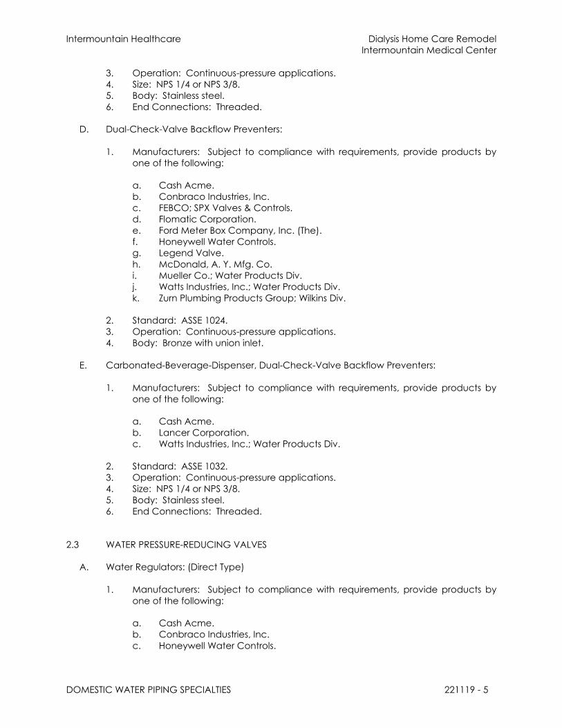
Intermountain Healthcare Dialysis Home Care Remodel
Intermountain Medical Center
DOMESTIC WATER PIPING SPECIALTIES 221119 - 5
3. Operation: Continuous-pressure applications.
4. Size: NPS 1/4 or NPS 3/8.
5. Body: Stainless steel.
6. End Connections: Threaded.
D. Dual-Check-Valve Backflow Preventers:
1. Manufacturers: Subject to compliance with requirements, provide products by
one of the following:
a. Cash Acme.
b. Conbraco Industries, Inc.
c. FEBCO; SPX Valves & Controls.
d. Flomatic Corporation.
e. Ford Meter Box Company, Inc. (The).
f. Honeywell Water Controls.
g. Legend Valve.
h. McDonald, A. Y. Mfg. Co.
i. Mueller Co.; Water Products Div.
j. Watts Industries, Inc.; Water Products Div.
k. Zurn Plumbing Products Group; Wilkins Div.
2. Standard: ASSE 1024.
3. Operation: Continuous-pressure applications.
4. Body: Bronze with union inlet.
E. Carbonated-Beverage-Dispenser, Dual-Check-Valve Backflow Preventers:
1. Manufacturers: Subject to compliance with requirements, provide products by
one of the following:
a. Cash Acme.
b. Lancer Corporation.
c. Watts Industries, Inc.; Water Products Div.
2. Standard: ASSE 1032.
3. Operation: Continuous-pressure applications.
4. Size: NPS 1/4 or NPS 3/8.
5. Body: Stainless steel.
6. End Connections: Threaded.
2.3 WATER PRESSURE-REDUCING VALVES
A. Water Regulators: (Direct Type)
1. Manufacturers: Subject to compliance with requirements, provide products by
one of the following:
a. Cash Acme.
b. Conbraco Industries, Inc.
c. Honeywell Water Controls.

Intermountain Healthcare Dialysis Home Care Remodel
Intermountain Medical Center
DOMESTIC WATER PIPING SPECIALTIES 221119 - 6
d. Watts Industries, Inc.; Water Products Div.
e. Zurn Plumbing Products Group; Wilkins Div.
2. Standard: ASSE 1003.
3. Pressure Rating: Initial working pressure of 150 psig.
4. Body: Bronze, provide chrome-plated finish if connected to chrome plated or
stainless steel piping for NPS 2 and smaller; cast iron with interior lining complying
with AWWA C550 or that is FDA approved for NPS 2-1/2 and NPS 3.
5. Valves for Booster Heater Water Supply: Include integral bypass.
6. End Connections: Threaded for NPS 2 and smaller; flanged for NPS 2-1/2 and
NPS 3.
B. Water Control Valves: (Pilot type)
1. Manufacturers: Subject to compliance with requirements, provide products by
one of the following:
a. CLA-VAL Automatic Control Valves.
b. Mifab Corp; Beeco.
c. Watts Industries, Inc.; Ames Fluid Control Systems.
d. Watts Industries, Inc.; Watts ACV.
e. Zurn Plumbing Products Group; Wilkins Div.
2. Description: Pilot-operation, diaphragm-type, single-seated main water control
valve.
3. Pressure Rating: Initial working pressure of 150 psig minimum with AWWA C550 or
FDA-approved, interior epoxy coating. Include small pilot-control valve, restrictor
device, specialty fittings, and sensor piping.
4. Main Valve Body: Cast- or ductile-iron body with AWWA C550 or FDA-approved,
interior epoxy coating; or stainless-steel body.
5. End Connections: Threaded for NPS 2 and smaller; flanged for NPS 2-1/2 and
larger.
2.4 BALANCING VALVES
A. Copper-Alloy Calibrated Balancing Valves:
1. Manufacturers: Subject to compliance with requirements, provide products by
one of the following:
a. Armstrong International, Inc.
b. Flo Fab Inc.
c. ITT Industries; Bell & Gossett Div.
d. NIBCO INC.
e. TAC Americas.
f. Taco, Inc.
g. Victaulic
h. Watts Industries, Inc.; Water Products Div.
2. Type: Ball or Y-pattern globe valve with two readout ports and memory setting
indicator.

Intermountain Healthcare Dialysis Home Care Remodel
Intermountain Medical Center
DOMESTIC WATER PIPING SPECIALTIES 221119 - 7
3. Body: bronze,
4. Size: Same as connected piping, but not larger than NPS 2.
5. Accessories: Meter hoses, fittings, valves, differential pressure meter, and carrying
case.
B. Cast-Iron Calibrated Balancing Valves:
1. Manufacturers: Subject to compliance with requirements, provide products by
one of the following:
a. Armstrong International, Inc.
b. Flo Fab Inc.
c. ITT Industries; Bell & Gossett Div.
d. NIBCO INC.
e. TAC Americas.
f. Watts Industries, Inc.; Water Products Div.
2. Type: Adjustable with Y-pattern globe valve, two readout ports, and memory-
setting indicator.
3. Size: Same as connected piping, but not smaller than NPS 2-1/2.
C. Accessories: Meter hoses, fittings, valves, differential pressure meter, and carrying case.
2.5 TEMPERATURE-ACTUATED WATER MIXING VALVES
A. Water-Temperature Limiting Devices:
1. Manufacturers: Subject to compliance with requirements, provide products by
one of the following:
a. Armstrong International, Inc.
b. Cash Acme.
c. Conbraco Industries, Inc.
d. Honeywell Water Controls.
e. Legend Valve.
f. Leonard Valve Company.
g. Powers; a Watts Industries Co.
h. Symmons Industries, Inc.
i. Taco, Inc.
j. Watts Industries, Inc.; Water Products Div.
k. Zurn Plumbing Products Group; Wilkins Div.
2. Standard: ASSE 1017.
3. Pressure Rating: 125 psig.
4. Type: Thermostatically controlled water mixing valve.
5. Material: Bronze body with corrosion-resistant interior components.
6. Connections: Threaded union inlets and outlet.
7. Accessories: Check stops on hot- and cold-water supplies, and adjustable,
temperature-control handle.
8. Valve Finish: Rough bronze.

Intermountain Healthcare Dialysis Home Care Remodel
Intermountain Medical Center
DOMESTIC WATER PIPING SPECIALTIES 221119 - 8
B. Primary, Thermostatic, Water Mixing Valves:
1. Manufacturers: Subject to compliance with requirements, provide products by
one of the following:
a. Armstrong International, Inc.
b. Lawler Manufacturing Company, Inc.
c. Leonard Valve Company.
d. Powers; a Watts Industries Co.
e. Symmons Industries, Inc.
2. Standard: ASSE 1017.
3. Pressure Rating: 125 psig.
4. Type: Exposed-mounting, thermostatically controlled water mixing valve.
5. Material: Bronze body with corrosion-resistant interior components.
6. Connections: Threaded union inlets and outlet.
7. Accessories: Manual temperature control, check stops on hot- and cold-water
supplies, and adjustable, temperature-control handle.
8. Valve Pressure Rating: 125 psig minimum, unless otherwise indicated.
9. Valve Finish: Chrome plated.
10. Piping Finish: Copper.
C. Individual-Fixture, Water Tempering Valves:
1. Manufacturers: Subject to compliance with requirements, provide products by
one of the following:
a. Cash Acme.
b. Conbraco Industries, Inc.
c. Honeywell Water Controls.
d. Lawler Manufacturing Company, Inc.
e. Leonard Valve Company.
f. Powers; a Watts Industries Co.
g. Watts Industries, Inc.; Water Products Div.
h. Zurn Plumbing Products Group; Wilkins Div.
2. Standard: ASSE 1070, thermostatically controlled water tempering valve.
3. Pressure Rating: 125 psig minimum, unless otherwise indicated.
4. Body: Bronze body with corrosion-resistant interior components.
5. Temperature Control: Adjustable.
6. Inlets and Outlet: Threaded.
7. Finish: Rough or chrome-plated bronze.
2.6 STRAINERS FOR DOMESTIC WATER PIPING
A. Y-Pattern Strainers:
1. Pressure Rating: 125 psig minimum, unless otherwise indicated.
2. Body: Bronze for NPS 2 and smaller; cast iron with interior lining complying with
AWWA C550 or FDA-approved, epoxy coating and for NPS 2-1/2 and larger.
3. End Connections: Threaded for NPS 2 and smaller; flanged for NPS 2-1/2 and

Intermountain Healthcare Dialysis Home Care Remodel
Intermountain Medical Center
DOMESTIC WATER PIPING SPECIALTIES 221119 - 9
larger.
4. Screen: Stainless steel with round perforations, unless otherwise indicated.
5. Perforation Size:
a. Strainers NPS 2 and Smaller: 0.020 inch.
b. Strainers NPS 2-1/2 to NPS 4: 0.045 inch.
c. Strainers NPS 5 and Larger: 0.10 inch.
6. Drain: Factory-installed, hose-end drain valve.
2.7 OUTLET BOXES
A. Icemaker Outlet Boxes:
1. Manufacturers: Subject to compliance with requirements, provide products by
one of the following:
a. Acorn Engineering Company.
b. Guy Gray Manufacturing Co., Inc.
c. IPS Corporation.
d. LSP Products Group, Inc.
e. Oatey.
f. Plastic Oddities; a division of Diverse Corporate Technologies.
g. Symmons Industries, Inc.
h. Watts Industries, Inc.; Water Products Div.
i. Whitehall Manufacturing; a div. of Acorn Engineering Company.
j. Zurn Plumbing Products Group; Light Commercial Operation.
2. Mounting: Recessed.
3. Material and Finish: Enameled-steel or epoxy-painted-steel or plastic box and
faceplate.
4. Faucet: Combination, valved fitting or separate hot- and cold-water, valved
fittings complying with ASME A112.18.1. Include garden-hose thread complying
with ASME B1.20.7 on outlets.
5. Supply Shutoff Fittings: NPS 1/2 gate, globe, or ball valves and NPS 1/2 copper,
water tubing.
6. Drain: NPS 2 standpipe and P-trap for direct waste connection to drainage
piping.
7. Inlet Hoses: Two 60-inch- long, rubber household clothes washer inlet hoses with
female, garden-hose-thread couplings. Include rubber washers.
8. Drain Hose: One 48-inch- long, rubber household clothes washer drain hose with
hooked end.
B. Water Outlet Boxes:
1. Manufacturers: Subject to compliance with requirements, provide products by
one of the following:
a. Acorn Engineering Company.
b. IPS Corporation.
c. LSP Products Group, Inc.
d. Oatey.

Intermountain Healthcare Dialysis Home Care Remodel
Intermountain Medical Center
DOMESTIC WATER PIPING SPECIALTIES 221119 - 10
e. Plastic Oddities; a division of Diverse Corporate Technologies.
2. Mounting: Recessed.
3. Material and Finish: Enameled-steel or epoxy-painted-steel or plastic box and
faceplate.
4. Faucet: Valved fitting complying with ASME A112.18.1. Include NPS 1/2 or smaller
copper tube outlet.
5. Supply Shutoff Fitting: NPS 1/2 gate, globe, or ball valve and NPS 1/2 copper,
water tubing.
2.8 DRAIN VALVES
A. Ball-Valve-Type, Hose-End Drain Valves:
1. Standard: MSS SP-110 for standard-port, two-piece ball valves.
2. Pressure Rating: 400-psig minimum CWP.
3. Size: NPS 3/4.
4. Body: Copper alloy.
5. Ball: Chrome-plated brass.
6. Seats and Seals: Replaceable.
7. Handle: Vinyl-covered steel.
8. Inlet: Threaded or solder joint.
9. Outlet: Threaded, short nipple with garden-hose thread complying with
ASME B1.20.7 and cap with brass chain.
2.9 WATER HAMMER ARRESTERS
A. Water Hammer Arresters:
1. Manufacturers: Subject to compliance with requirements, provide products by
one of the following:
a. AMTROL, Inc.
b. Josam Company.
c. MIFAB, Inc.
d. PPP Inc.
e. Sioux Chief Manufacturing Company, Inc.
f. Smith, Jay R. Mfg. Co.; Division of Smith Industries, Inc.
g. Tyler Pipe; Wade Div.
h. Watts Drainage Products Inc.
i. Zurn Plumbing Products Group; Specification Drainage Operation.
2. Standard: ASSE 1010 or PDI-WH 201.
3. Type: Metal bellows or Copper tube with piston.
4. Size: ASSE 1010, Sizes AA and A through F or PDI-WH 201, Sizes A through F.
2.10 TRAP-SEAL PRIMER VALVES
A. Trap Seal Primer Valves: ASSE 1018, water-supply-fed type, with the following
characteristics:
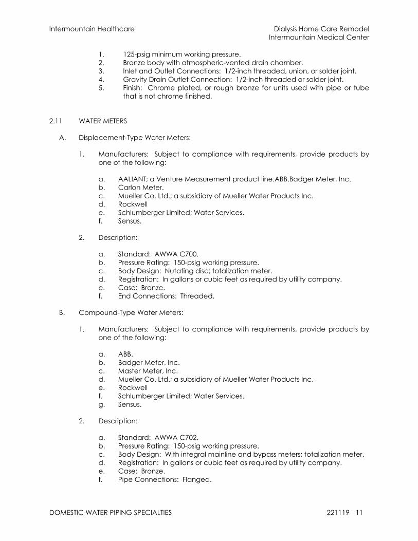
Intermountain Healthcare Dialysis Home Care Remodel
Intermountain Medical Center
DOMESTIC WATER PIPING SPECIALTIES 221119 - 11
1. 125-psig minimum working pressure.
2. Bronze body with atmospheric-vented drain chamber.
3. Inlet and Outlet Connections: 1/2-inch threaded, union, or solder joint.
4. Gravity Drain Outlet Connection: 1/2-inch threaded or solder joint.
5. Finish: Chrome plated, or rough bronze for units used with pipe or tube
that is not chrome finished.
2.11 WATER METERS
A. Displacement-Type Water Meters:
1. Manufacturers: Subject to compliance with requirements, provide products by
one of the following:
a. AALIANT; a Venture Measurement product line.ABB.Badger Meter, Inc.
b. Carlon Meter.
c. Mueller Co. Ltd.; a subsidiary of Mueller Water Products Inc.
d. Rockwell
e. Schlumberger Limited; Water Services.
f. Sensus.
2. Description:
a. Standard: AWWA C700.
b. Pressure Rating: 150-psig working pressure.
c. Body Design: Nutating disc; totalization meter.
d. Registration: In gallons or cubic feet as required by utility company.
e. Case: Bronze.
f. End Connections: Threaded.
B. Compound-Type Water Meters:
1. Manufacturers: Subject to compliance with requirements, provide products by
one of the following:
a. ABB.
b. Badger Meter, Inc.
c. Master Meter, Inc.
d. Mueller Co. Ltd.; a subsidiary of Mueller Water Products Inc.
e. Rockwell
f. Schlumberger Limited; Water Services.
g. Sensus.
2. Description:
a. Standard: AWWA C702.
b. Pressure Rating: 150-psig working pressure.
c. Body Design: With integral mainline and bypass meters; totalization meter.
d. Registration: In gallons or cubic feet as required by utility company.
e. Case: Bronze.
f. Pipe Connections: Flanged.

Intermountain Healthcare Dialysis Home Care Remodel
Intermountain Medical Center
DOMESTIC WATER PIPING SPECIALTIES 221119 - 12
C. Remote Registration System: Direct-reading type complying with AWWA C706;
modified with signal-transmitting assembly, low-voltage connecting wiring, and remote
register assembly as required by utility company.
PART 3 - EXECUTION
3.1 INSTALLATION
A. Refer to Division 22 Section "Common Work Results for Plumbing" for piping joining
materials, joint construction, and basic installation requirements.
B. Install backflow preventers in each water supply to mechanical equipment and systems
and to other equipment and water systems that may be sources of contamination.
Comply with authorities having jurisdiction.
1. Locate backflow preventers in same room as connected equipment or system.
2. Install drain for backflow preventers with atmospheric-vent drain connection with
air-gap fitting, fixed air-gap fitting, or equivalent positive pipe separation of at
least two pipe diameters in drain piping and pipe to floor drain. Locate air-gap
device attached to or under backflow preventer. Simple air breaks are not
acceptable for this application.
3. Do not install bypass piping around backflow preventers.
C. Install water control valves with inlet and outlet shutoff valves. Install pressure gages on
inlet and outlet.
D. Install balancing valves in locations where they can easily be adjusted.
E. Install temperature-actuated water mixing valves with check stops or shutoff valves on
inlets and with shutoff valve on outlet.
1. Install thermometers and water regulators if specified.
2. Install cabinet-type units recessed in or surface mounted on wall as specified.
F. Install Y-pattern strainers for water on supply side of each control valve, water pressure-
reducing valve, solenoid valve, and pump.
G. Install outlet boxes recessed in wall. Install 2-by-4-inch fire-retardant-treated-wood
blocking wall reinforcement between studs. Fire-retardant-treated-wood blocking is
specified in Division 06 Section "Rough Carpentry."
H. Install water hammer arresters in water piping according to PDI-WH 201, which includes
on all fast closing valves.
I. Install supply-type, trap-seal primer valves with outlet piping pitched down toward drain
trap a minimum of 1 percent, and connect to floor-drain body, trap, or inlet fitting.
Adjust valve for proper flow.
J. Install drainage-type, trap-seal primer valves as lavatory trap with outlet piping pitched
down toward drain trap a minimum of 1 percent, and connect to floor-drain body,
trap, or inlet fitting.

Intermountain Healthcare Dialysis Home Care Remodel
Intermountain Medical Center
DOMESTIC WATER PIPING SPECIALTIES 221119 - 13
K. Install trap-seal primer systems with outlet piping pitched down toward drain trap a
minimum of 1 percent, and connect to floor-drain body, trap, or inlet fitting. Adjust
system for proper flow.
L. Install water meters per manufacturers requirements.
3.2 CONNECTIONS
A. Piping installation requirements are specified in other Division 22 Sections. Drawings
indicate general arrangement of piping and specialties.
B. Ground equipment according to Division 26 Section "Grounding and Bonding for
Electrical Systems."
C. Connect wiring according to Division 26 Section "Low-Voltage Electrical Power
Conductors and Cables."
3.3 LABELING AND IDENTIFYING
A. Equipment Nameplates and Signs: Install engraved plastic-laminate equipment
nameplate or sign on or near each of the following:
1. Pressure vacuum breakers.
2. Reduced-pressure-principle backflow preventers.
3. Double-check backflow-prevention assemblies.
4. Carbonated-beverage-machine backflow preventers.
5. Dual-check-valve backflow preventers.
6. Water pressure-reducing valves.
7. Calibrated balancing valves.
8. Primary, thermostatic, water mixing valves.
9. Primary water tempering valves.
10. Outlet boxes.
11. Supply-type, trap-seal primer valves.
B. Distinguish among multiple units, inform operator of operational requirements, indicate
safety and emergency precautions, and warn of hazards and improper operations, in
addition to identifying unit. Nameplates and signs are specified in Division 22 Section
"Identification for Plumbing Piping and Equipment."
3.4 FIELD QUALITY CONTROL
A. Perform the following tests and prepare test reports:
1. Test each backflow preventer according to authorities having jurisdiction and the
device's reference standard.
B. Remove and replace malfunctioning domestic water piping specialties and retest as
specified above.

Intermountain Healthcare Dialysis Home Care Remodel
Intermountain Medical Center
DOMESTIC WATER PIPING SPECIALTIES 221119 - 14
3.5 ADJUSTING
A. Set field-adjustable pressure set points of water pressure-reducing valves.
B. Set field-adjustable flow set points of balancing valves.
C. Set field-adjustable temperature set points of temperature-actuated water mixing
valves.
END OF SECTION 221119

Intermountain Healthcare Dialysis Home Care Remodel
Intermountain Medical Center
SANITARY WASTE PIPING SPECIALTIES 221319 - 1
SECTION 221319 - SANITARY WASTE PIPING SPECIALTIES
PART 1 - GENERAL
1.1 RELATED DOCUMENTS
A. Drawings and general provisions of the Contract, including General and
Supplementary Conditions and Division 01 Specification Sections, apply to this Section.
1.2 SUMMARY
A. This Section includes the following sanitary drainage piping specialties:
1. Cleanouts.
2. Floor drains.
3. Channel drainage systems.
4. Roof flashing assemblies.
5. Through-penetration firestop assemblies.
6. Miscellaneous sanitary drainage piping specialties.
7. Flashing materials.
B. Related Sections include the following:
1. Division 22 Section "Storm Drainage Piping Specialties" for trench drains for storm
water, channel drainage systems for storm water, roof drains, and catch basins.
1.3 SEISMIC REQUIREMENTS
A. Seismic Performance: Plumbing equipment, hangers and supports shall withstand the
effects of earthquake motions determined according to SEI/ASCE 7 and with the
requirements specified in Section 220548 “Vibration and Seismic Controls for Plumbing
Piping and Equipment.
1.4 DEFINITIONS
A. FOG: Fats, oils, and greases.
B. FRP: Fiberglass-reinforced plastic.
C. HDPE: High-density polyethylene plastic.
D. PE: Polyethylene plastic.
E. PP: Polypropylene plastic.
F. PVC: Polyvinyl chloride plastic.

Intermountain Healthcare Dialysis Home Care Remodel
Intermountain Medical Center
SANITARY WASTE PIPING SPECIALTIES 221319 - 2
1.5 SUBMITTALS
A. Product Data: For each type of product indicated.
B. Field quality-control test reports.
C. Operation and Maintenance Data: For drainage piping specialties to include in
emergency, operation, and maintenance manuals.
1.6 QUALITY ASSURANCE
A. Drainage piping specialties shall bear label, stamp, or other markings of specified
testing agency.
B. Comply with NSF 14, "Plastics Piping Components and Related Materials," for plastic
sanitary piping specialty components.
1.7 COORDINATION
A. Coordinate size and location of concrete bases. Cast anchor-bolt inserts into bases.
Concrete, reinforcement, and formwork requirements are specified in Division 03.
B. Coordinate size and location of roof penetrations.
PART 2 - PRODUCTS
2.1 CLEANOUTS
A. Exposed Metal Cleanouts:
1. Manufacturers: Subject to compliance with requirements, provide products by
one of the following:
a. Josam Company; Josam Div.
b. MIFAB, Inc.
c. Smith, Jay R. Mfg. Co.; Division of Smith Industries, Inc.
d. Tyler Pipe; Wade Div.
e. Watts Drainage Products Inc.
f. Zurn Plumbing Products Group; Specification Drainage Operation.
2. Standard: ASME A112.36.2M for cast iron for cleanout test tee.
3. Size: Same as connected drainage piping
4. Body Material: Hubless, cast-iron soil pipe test tee as required to match
connected piping.
5. Closure: Countersunk, brass plug.
6. Closure Plug Size: Same as or not more than one size smaller than cleanout size.
7. Closure: Stainless-steel plug with seal.
B. Metal Floor Cleanouts:

Intermountain Healthcare Dialysis Home Care Remodel
Intermountain Medical Center
SANITARY WASTE PIPING SPECIALTIES 221319 - 3
1. Manufacturers: Subject to compliance with requirements, provide products by
one of the following:
a. Josam Company; Josam Div.
b. Oatey.
c. Smith, Jay R. Mfg. Co.; Division of Smith Industries, Inc.
d. Tyler Pipe; Wade Div.
e. Watts Drainage Products Inc.
f. Zurn Plumbing Products Group; Light Commercial Operation.
g. Zurn Plumbing Products Group; Specification Drainage Operation.
2. Standard: ASME A112.36.2M for adjustable housing cleanout.
3. Size: Same as connected branch.
4. Type: Adjustable housing.
5. Body or Ferrule: Cast iron.
6. Clamping Device: Required.
7. Outlet Connection: Inside calk.
8. Closure: Brass plug with tapered threads.
9. Adjustable Housing Material: Cast iron with threads.
10. Frame and Cover Material and Finish: Nickel-bronze, copper alloy.
11. Frame and Cover Shape: Round.
12. Top Loading Classification: Heavy Duty.
13. Riser: ASTM A 74, Service class, cast-iron drainage pipe fitting and riser to
cleanout.
14. Standard: ASME A112.3.1.
15. Size: Same as connected branch.
16. Housing: Stainless steel.
17. Closure: Stainless steel with seal.
18. Riser: Stainless-steel drainage pipe fitting to cleanout.
C. Cast-Iron Wall Cleanouts:
1. Manufacturers: Subject to compliance with requirements, provide products by
one of the following:
a. Josam Company; Josam Div.
b. MIFAB, Inc.
c. Smith, Jay R. Mfg. Co.; Division of Smith Industries, Inc.
d. Tyler Pipe; Wade Div.
e. Watts Drainage Products Inc.
f. Zurn Plumbing Products Group; Specification Drainage Operation.
2. Standard: ASME A112.36.2M. Include wall access.
3. Size: Same as connected drainage piping.
4. Body: Hub-and-spigot, cast-iron soil pipe T-branch as required to match
connected piping.
5. Closure: Countersunk, brass plug.
6. Closure Plug Size: Same as or not more than one size smaller than cleanout size.
7. Wall Access: Round, flat, chrome-plated brass or stainless-steel cover plate with
screw.
8. Wall Access: Round, stainless-steel wall-installation frame and cover.
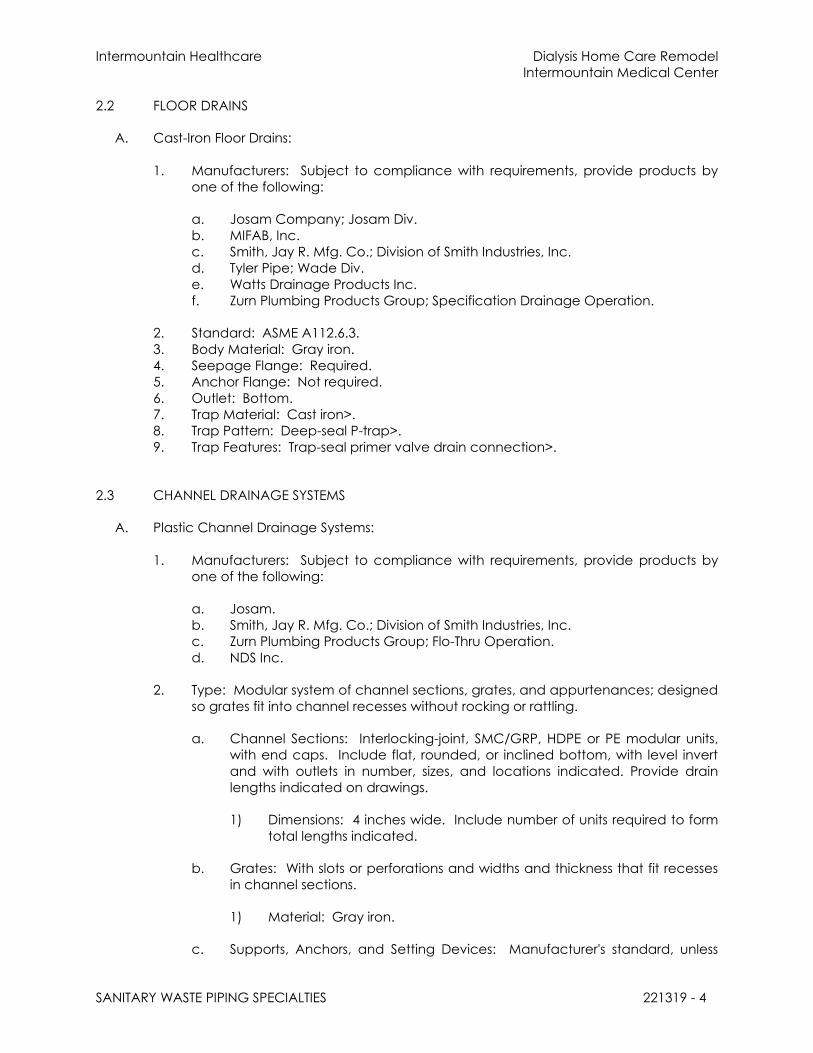
Intermountain Healthcare Dialysis Home Care Remodel
Intermountain Medical Center
SANITARY WASTE PIPING SPECIALTIES 221319 - 4
2.2 FLOOR DRAINS
A. Cast-Iron Floor Drains:
1. Manufacturers: Subject to compliance with requirements, provide products by
one of the following:
a. Josam Company; Josam Div.
b. MIFAB, Inc.
c. Smith, Jay R. Mfg. Co.; Division of Smith Industries, Inc.
d. Tyler Pipe; Wade Div.
e. Watts Drainage Products Inc.
f. Zurn Plumbing Products Group; Specification Drainage Operation.
2. Standard: ASME A112.6.3.
3. Body Material: Gray iron.
4. Seepage Flange: Required.
5. Anchor Flange: Not required.
6. Outlet: Bottom.
7. Trap Material: Cast iron>.
8. Trap Pattern: Deep-seal P-trap>.
9. Trap Features: Trap-seal primer valve drain connection>.
2.3 CHANNEL DRAINAGE SYSTEMS
A. Plastic Channel Drainage Systems:
1. Manufacturers: Subject to compliance with requirements, provide products by
one of the following:
a. Josam.
b. Smith, Jay R. Mfg. Co.; Division of Smith Industries, Inc.
c. Zurn Plumbing Products Group; Flo-Thru Operation.
d. NDS Inc.
2. Type: Modular system of channel sections, grates, and appurtenances; designed
so grates fit into channel recesses without rocking or rattling.
a. Channel Sections: Interlocking-joint, SMC/GRP, HDPE or PE modular units,
with end caps. Include flat, rounded, or inclined bottom, with level invert
and with outlets in number, sizes, and locations indicated. Provide drain
lengths indicated on drawings.
1) Dimensions: 4 inches wide. Include number of units required to form
total lengths indicated.
b. Grates: With slots or perforations and widths and thickness that fit recesses
in channel sections.
1) Material: Gray iron.
c. Supports, Anchors, and Setting Devices: Manufacturer's standard, unless

Intermountain Healthcare Dialysis Home Care Remodel
Intermountain Medical Center
SANITARY WASTE PIPING SPECIALTIES 221319 - 5
otherwise indicated.
d. Channel-Section Joining and Fastening Materials: As recommended by
system manufacturer.
2.4 THROUGH-PENETRATION FIRESTOP ASSEMBLIES
A. Through-Penetration Firestop Assemblies:
1. Available Manufacturers: Subject to compliance with requirements,
manufacturers offering products that may be incorporated into the Work include,
but are not limited to, the following:
2. Manufacturers: Subject to compliance with requirements, provide products by
one of the following:
a. ProSet Systems Inc.
3. Standard: UL 1479 assembly of sleeve and stack fitting with firestopping plug.
4. Size: Same as connected soil, waste, or vent stack.
5. Sleeve: Molded PVC plastic, of length to match slab thickness and with integral
nailing flange on one end for installation in cast-in-place concrete slabs.
6. Stack Fitting: ASTM A 48/A 48M, gray-iron, hubless-pattern, wye branch with
neoprene O-ring at base and gray-iron plug in thermal-release harness. Include
PVC protective cap for plug.
7. Special Coating: Corrosion resistant on interior of fittings.
2.5 MISCELLANEOUS SANITARY DRAINAGE PIPING SPECIALTIES
A. Deep-Seal Traps:
1. Description: Cast-iron or bronze casting, with inlet and outlet matching
connected piping and cleanout trap-seal primer valve connection.
2. Size: Same as connected waste piping.
a. NPS 2: 4-inch- minimum water seal.
b. NPS 2-1/2 and Larger: 5-inch- minimum water seal.
B. Floor-Drain, Trap-Seal Primer Fittings:
1. Description: Cast iron, with threaded inlet and threaded or spigot outlet, and
trap-seal primer valve connection.
2. Size: Same as floor drain outlet with NPS 1/2 side inlet.
C. Air-Gap Fittings:
1. Standard: ASME A112.1.2, for fitting designed to ensure fixed, positive air gap
between installed inlet and outlet piping.
2. Body: Bronze or cast iron.
3. Inlet: Opening in top of body.
4. Outlet: Larger than inlet.
5. Size: Same as connected waste piping and with inlet large enough for
associated indirect waste piping.

Intermountain Healthcare Dialysis Home Care Remodel
Intermountain Medical Center
SANITARY WASTE PIPING SPECIALTIES 221319 - 6
D. Sleeve Flashing Device:
1. Description: Manufactured, cast-iron fitting, with clamping device, that forms
sleeve for pipe floor penetrations of floor membrane. Include galvanized-steel
pipe extension in top of fitting that will extend 1 inch > above finished floor and
galvanized-steel pipe extension in bottom of fitting that will extend through floor
slab.
2. Size: As required for close fit to riser or stack piping.
E. Stack Flashing Fittings:
1. Description: Counterflashing-type, cast-iron fitting, with bottom recess for
terminating roof membrane, and with threaded or hub top for extending vent
pipe.
2. Size: Same as connected stack vent or vent stack.
F. Vent Cap Filters:
1. Description: Activated carbon filter in housing for installation at vent terminal as
manufactured by Sweet Filter.
2. Size: Same as connected stack vent or vent stack.
2.6 FLASHING MATERIALS
A. Lead Sheet: ASTM B 749, Type L51121, copper bearing, with the following minimum
weights and thicknesses, unless otherwise indicated:
1. General Use: 4.0-lb/sq. ft., 0.0625-inch thickness.
2. Vent Pipe Flashing: 3.0-lb/sq. ft., 0.0469-inch thickness.
3. Burning: 6-lb/sq. ft., 0.0938-inch thickness.
B. Elastic Membrane Sheet: ASTM D 4068, flexible, chlorinated polyethylene, 40-mil
minimum thickness.
C. Fasteners: Metal compatible with material and substrate being fastened.
D. Metal Accessories: Sheet metal strips, clamps, anchoring devices, and similar
accessory units required for installation; matching or compatible with material being
installed.
E. Bituminous Coating: SSPC-Paint 12, solvent-type, bituminous mastic.
PART 3 - EXECUTION
3.1 INSTALLATION
A. Comply with requirements for seismic-restraint devices in Section 220548 "Vibration and
Seismic Controls for Plumbing Piping and Equipment."
B. Refer to Division 22 Section "Common Work Results for Plumbing" for piping joining

Intermountain Healthcare Dialysis Home Care Remodel
Intermountain Medical Center
SANITARY WASTE PIPING SPECIALTIES 221319 - 7
materials, joint construction, and basic installation requirements.
C. Install backwater valves in building drain piping. For interior installation, provide
cleanout deck plate flush with floor and centered over backwater valve cover, and of
adequate size to remove valve cover for servicing.
D. Install cleanouts in aboveground piping and building drain piping according to the
following, unless otherwise indicated:
1. Size same as drainage piping up to NPS 4. Use NPS 4 for larger drainage piping
unless larger cleanout is indicated.
2. Locate at each change in direction of piping greater than 45 degrees.
3. Locate at minimum intervals of 50 feet for piping NPS 4 and smaller and 100 feet
for larger piping.
4. Locate at base of each vertical soil and waste stack.
E. For floor cleanouts for piping below floors, install cleanout deck plates with top flush
with finished floor.
F. For cleanouts located in concealed piping, install cleanout wall access covers, of types
indicated, with frame and cover flush with finished wall.
G. Install floor drains at low points of surface areas to be drained. Set grates of drains flush
with finished floor, unless otherwise indicated.
1. Position floor drains for easy access and maintenance.
2. Set floor drains below elevation of surrounding finished floor to allow floor
drainage. Set with grates depressed according to the following drainage area
radii:
a. Radius, 30 Inches or Less: Equivalent to 1 percent slope, but not less than
1/4-inch total depression.
b. Radius, 30 to 60 Inches: Equivalent to 1 percent slope.
c. Radius, 60 Inches or Larger: Equivalent to 1 percent slope, but not greater
than 1-inch total depression.
3. Install floor-drain flashing collar or flange so no leakage occurs between drain
and adjoining flooring. Maintain integrity of waterproof membranes where
penetrated.
4. Install individual traps for floor drains connected to sanitary building drain, unless
otherwise indicated.
H. Assemble plastic channel drainage system components according to manufacturer's
written instructions. Install on support devices so that top will be flush with adjacent
surface.
I. Assemble stainless steel channel drainage system components according to
manufacturer's written instructions. Install on support devices so that top will be flush
with adjacent surface.
J. Install deep-seal traps on all floor drains and other waste outlets, if indicated.
K. Install floor-drain, trap-seal primer fittings on inlet to floor drains that require trap-seal

Intermountain Healthcare Dialysis Home Care Remodel
Intermountain Medical Center
SANITARY WASTE PIPING SPECIALTIES 221319 - 8
primer connection.
1. Exception: Fitting may be omitted if trap has trap-seal primer connection.
2. Size: Same as floor drain inlet.
L. Install air-gap fittings on draining-type backflow preventers and on indirect-waste
piping discharge into sanitary drainage system.
M. Install sleeve flashing device with each riser and stack passing through floors with
waterproof membrane.
N. Install vent cap filters on each vent pipe passing through roof.
O. Install wood-blocking reinforcement for wall-mounting-type specialties.
P. Install traps on plumbing specialty drain outlets. Omit traps on indirect wastes unless
trap is indicated.
Q. Install escutcheons at wall, floor, and ceiling penetrations in exposed finished locations
and within cabinets and millwork. Use deep-pattern escutcheons if required to
conceal protruding pipe fittings.
3.2 CONNECTIONS
A. Piping installation requirements are specified in other Division 22 Sections. Drawings
indicate general arrangement of piping, fittings, and specialties.
B. Install piping adjacent to equipment to allow service and maintenance.
3.3 FLASHING INSTALLATION
A. Fabricate flashing from single piece unless large pans, sumps, or other drainage shapes
are required. Join flashing according to the following if required:
1. Lead Sheets: Burn joints of lead sheets 6.0-lb/sq. ft., 0.0938-inch thickness or
thicker. Solder joints of lead sheets 4.0-lb/sq. ft., 0.0625-inch thickness or thinner.
B. Install sheet flashing on pipes, sleeves, and specialties passing through or embedded in
floors and roofs with waterproof membrane.
1. Pipe Flashing: Sleeve type, matching pipe size, with minimum length of 10 inches,
and skirt or flange extending at least 8 inches around pipe.
2. Sleeve Flashing: Flat sheet, with skirt or flange extending at least 8 inches around
sleeve.
3. Embedded Specialty Flashing: Flat sheet, with skirt or flange extending at least 8
inches around specialty.
C. Set flashing on floors and roofs in solid coating of bituminous cement.
D. Secure flashing into sleeve and specialty clamping ring or device.

Intermountain Healthcare Dialysis Home Care Remodel
Intermountain Medical Center
SANITARY WASTE PIPING SPECIALTIES 221319 - 9
E. Install flashing for piping passing through roofs with counterflashing or commercially
made flashing fittings, according to Division 07 Section "Sheet Metal Flashing and Trim."
F. Extend flashing up vent pipe passing through roofs and turn down into pipe, or secure
flashing into cast-iron sleeve having calking recess.
G. Fabricate and install flashing and pans, sumps, and other drainage shapes.
3.4 FIELD QUALITY CONTROL
A. Perform tests and inspections and prepare test reports.
B. Tests and Inspections:
1. Leak Test: After installation, charge system and test for leaks. Repair leaks and
retest until no leaks exist.
2. Test and adjust controls and safeties. Replace damaged and malfunctioning
controls and equipment.
3.5 PROTECTION
A. Protect drains during remainder of construction period to avoid clogging with dirt or
debris and to prevent damage from traffic or construction work.
B. Place plugs in ends of uncompleted piping at end of each day or when work stops.
END OF SECTION 221319

Intermountain Healthcare Dialysis Home Care Remodel
Intermountain Medical Center
PLUMBING FIXTURES 224000 - 1
SECTION 224000 - PLUMBING FIXTURES
PART 1 - GENERAL
1.1 RELATED DOCUMENTS
A. Drawings and general provisions of the Contract, including General and
Supplementary Conditions and Division 01 Specification Sections, apply to this Section.
1.2 SUMMARY
A. This Section includes the following conventional plumbing fixtures and related
components:
1. Faucets for lavatories bathtub/showers showers and sinks.
2. Flushometers.
3. Toilet seats.
4. Protective shielding guards.
5. Fixture supports.
6. Water closets.
7. Urinals.
8. Lavatories.
9. Commercial sinks.
10. Bathtubs.
11. Service sinks.
B. Related Sections include the following:
1. Division 10 Section "Toilet, Bath, and Laundry Accessories."
2. Division 22 Section "Domestic Water Piping Specialties" for backflow preventers,
floor drains, and specialty fixtures not included in this Section.
3. Division 22 Section "Emergency Plumbing Fixtures."
4. Division 22 Section "Drinking Fountains and Water Coolers."
1.3 DEFINITIONS
A. Accessible Fixture: Plumbing fixture that can be approached, entered, and used by
people with disabilities.
B. Cast Polymer: Cast-filled-polymer-plastic material. This material includes cultured-
marble and solid-surface materials.
C. Cultured Marble: Cast-filled-polymer-plastic material with surface coating.
D. Fitting: Device that controls the flow of water into or out of the plumbing fixture. Fittings
specified in this Section include supplies and stops, faucets and spouts, shower heads
and tub spouts, drains and tailpieces, and traps and waste pipes. Piping and general-
duty valves are included where indicated.

Intermountain Healthcare Dialysis Home Care Remodel
Intermountain Medical Center
PLUMBING FIXTURES 224000 - 2
E. FRP: Fiberglass-reinforced plastic.
F. PMMA: Polymethyl methacrylate (acrylic) plastic.
G. PVC: Polyvinyl chloride plastic.
H. Solid Surface: Nonporous, homogeneous, cast-polymer-plastic material with heat-,
impact-, scratch-, and stain-resistance qualities.
1.4 SUBMITTALS
A. Product Data: For each type of plumbing fixture indicated. Include selected fixture
and trim, fittings, accessories, appliances, appurtenances, equipment, and supports.
Indicate materials and finishes, dimensions, construction details, and flow-control rates.
B. Shop Drawings: Diagram power, signal, and control wiring.
C. Operation and Maintenance Data: For plumbing fixtures to include in emergency,
operation, and maintenance manuals.
D. Warranty: Special warranty specified in this Section.
1.5 QUALITY ASSURANCE
A. Source Limitations: Obtain plumbing fixtures, faucets, and other components of each
category through one source from a single manufacturer.
1. Exception: If fixtures, faucets, or other components are not available from a
single manufacturer, obtain similar products from other manufacturers specified
for that category.
B. Electrical Components, Devices, and Accessories: Listed and labeled as defined in
NFPA 70, Article 100, by a testing agency acceptable to authorities having jurisdiction,
and marked for intended use.
C. Regulatory Requirements: Comply with requirements in ICC A117.1, "Accessible and
Usable Buildings and Facilities"; Public Law 90-480, "Architectural Barriers Act"; and Public
Law 101-336, "Americans with Disabilities Act"; for plumbing fixtures for people with
disabilities.
D. Regulatory Requirements: Comply with requirements in Public Law 102-486, "Energy
Policy Act," about water flow and consumption rates for plumbing fixtures.
E. NSF Standard: Comply with NSF 61, "Drinking Water System Components--Health
Effects," for fixture materials that will be in contact with potable water.
F. Select combinations of fixtures and trim, faucets, fittings, and other components that
are compatible.
G. Comply with the following applicable standards and other requirements specified for
plumbing fixtures:

Intermountain Healthcare Dialysis Home Care Remodel
Intermountain Medical Center
PLUMBING FIXTURES 224000 - 3
1. Enameled, Cast-Iron Fixtures: ASME A112.19.1M.
2. Porcelain-Enameled, Formed-Steel Fixtures: ASME A112.19.4M.
3. Slip-Resistant Bathing Surfaces: ASTM F 462.
4. Solid-Surface-Material Lavatories and Sinks: ANSI/ICPA SS-1.
5. Stainless-Steel Residential Sinks: ASME A112.19.3.
6. Vitreous-China Fixtures: ASME A112.19.2M.
7. Water-Closet, Flushometer Tank Trim: ASSE 1037.
8. Whirlpool Bathtub Fittings: ASME A112.19.8M.
H. Comply with the following applicable standards and other requirements specified for
lavatory and sink faucets:
1. Backflow Protection Devices for Faucets with Side Spray: ASME A112.18.3M.
2. Backflow Protection Devices for Faucets with Hose-Thread Outlet:
ASME A112.18.3M.
3. Diverter Valves for Faucets with Hose Spray: ASSE 1025.
4. Faucets: ASME A112.18.1.
5. Hose-Connection Vacuum Breakers: ASSE 1011.
6. Hose-Coupling Threads: ASME B1.20.7.
7. Integral, Atmospheric Vacuum Breakers: ASSE 1001.
8. NSF Potable-Water Materials: NSF 61.
9. Pipe Threads: ASME B1.20.1.
10. Sensor-Actuated Faucets and Electrical Devices: UL 1951.
11. Supply Fittings: ASME A112.18.1.
12. Brass Waste Fittings: ASME A112.18.2.
13. NSF61 Appendage G-AB 1953. Lead free potable drinking faucets.
I. Comply with the following applicable standards and other requirements specified for
bathtub/shower and shower faucets:
1. Backflow Protection Devices for Hand-Held Showers: ASME A112.18.3M.
2. Combination, Pressure-Equalizing and Thermostatic-Control Antiscald Faucets:
ASSE 1016.
3. Deck-Mounted Bath/Shower Transfer Valves: ASME 18.7.
4. Faucets: ASME A112.18.1.
5. Hand-Held Showers: ASSE 1014.
6. High-Temperature-Limit Controls for Thermal-Shock-Preventing Devices:
ASTM F 445.
7. Hose-Coupling Threads: ASME B1.20.7.
8. Manual-Control Antiscald Faucets: ASTM F 444.
9. Pipe Threads: ASME B1.20.1.
10. Pressure-Equalizing-Control Antiscald Faucets: ASTM F 444 and ASSE 1016.
11. Sensor-Actuated Faucets and Electrical Devices: UL 1951.
12. Thermostatic-Control Antiscald Faucets: ASTM F 444 and ASSE 1016.
J. Comply with the following applicable standards and other requirements specified for
miscellaneous fittings:
1. Atmospheric Vacuum Breakers: ASSE 1001.
2. Brass and Copper Supplies: ASME A112.18.1.
3. Dishwasher Air-Gap Fittings: ASSE 1021.
4. Manual-Operation Flushometers: ASSE 1037.

Intermountain Healthcare Dialysis Home Care Remodel
Intermountain Medical Center
PLUMBING FIXTURES 224000 - 4
5. Plastic Tubular Fittings: ASTM F 409.
6. Brass Waste Fittings: ASME A112.18.2.
7. Sensor-Operation Flushometers: ASSE 1037 and UL 1951.
8. NSF61 Appendage G-AB 1953. Lead free potable drinking faucets.
K. Comply with the following applicable standards and other requirements specified for
miscellaneous components:
1. Disposers: ASSE 1008 and UL 430.
2. Dishwasher Air-Gap Fittings: ASSE 1021.
3. Flexible Water Connectors: ASME A112.18.6.
4. Floor Drains: ASME A112.6.3.
5. Grab Bars: ASTM F 446.
6. Hose-Coupling Threads: ASME B1.20.7.
7. Off-Floor Fixture Supports: ASME A112.6.1M.
8. Pipe Threads: ASME B1.20.1.
9. Plastic Toilet Seats: ANSI Z124.5.
10. Supply and Drain Protective Shielding Guards: ICC A117.1.
1.6 EXTRA MATERIALS
A. Furnish extra materials described below that match products installed and that are
packaged with protective covering for storage and identified with labels describing
contents.
1. Faucet Washers and O-Rings: Equal to 10 percent of amount of each type and
size installed.
2. Faucet Cartridges and O-Rings: Equal to 5 percent of amount of each type and
size installed.
3. Flushometer Valve, Repair Kits: Equal to 10 percent of amount of each type
installed, but no fewer than 12 of each type.
4. Provide hinged-top wood or metal box, or individual metal boxes, with separate
compartments for each type and size of extra materials listed above.
5. Toilet Seats: Equal to 5 percent of amount of each type installed.
PART 2 - PRODUCTS
2.1 LAVATORY FAUCETS
A. Lavatory Faucets:
1. Manufacturers: Subject to compliance with requirements, provide products by
one of the following:
a. Chicago Faucets.
b. T & S Brass and Bronze Works, Inc.
c. Moen, Inc.
2.2 SINK FAUCETS

Intermountain Healthcare Dialysis Home Care Remodel
Intermountain Medical Center
PLUMBING FIXTURES 224000 - 5
A. Sink Faucets:
1. Manufacturers: Subject to compliance with requirements, provide products by
one of the following:
a. Chicago Faucets.
b. T & S Brass and Bronze Works, Inc.
c. Moen, Inc.
2.3 FLUSHOMETERS
A. Flushometers:
1. Manufacturers: Subject to compliance with requirements, provide products by
one of the following:
a. Sloan Valve Company.
b. Moen, Inc.
2.4 TOILET SEATS
A. Toilet Seats:
1. Manufacturers: Subject to compliance with requirements, provide products by
one of the following:
a. Bemis Manufacturing Company.
b. Centoco Manufacturing Corp.
c. Church Seats.
d. Olsonite Corp.
e. Sperzel.
2. Description: Toilet seat for water-closet-type fixture.
a. Material: Molded, solid plastic with antimicrobial agent.
b. Configuration: Open front without cover.
c. Size: Elongated.
d. Hinge Type: CK, check.
e. Class: Heavy-duty commercial.
f. Color: White.
2.5 PROTECTIVE SHIELDING GUARDS
A. Protective Shielding Pipe Covers:
1. Manufacturers: Subject to compliance with requirements, provide products by
one of the following:
a. Engineered Brass Co.
b. Insul-Tect Products Co.; a Subsidiary of MVG Molded Products.

Intermountain Healthcare Dialysis Home Care Remodel
Intermountain Medical Center
PLUMBING FIXTURES 224000 - 6
c. McGuire Manufacturing Co., Inc.
d. Plumberex Specialty Products Inc.
e. TCI Products.
f. TRUEBRO, Inc.
g. Zurn Plumbing Products Group; Tubular Brass Plumbing Products Operation.
2. Description: Manufactured plastic wraps for covering plumbing fixture hot- and
cold-water supplies and trap and drain piping. Comply with Americans with
Disabilities Act (ADA) requirements. Product shall also meet the ASTM E 84 25/450
smoke and flame rating.
B. Protective Shielding Piping Enclosures:
1. Manufacturers: Subject to compliance with requirements, provide products by
one of the following:
a. TRUEBRO, Inc.
2. Description: Manufactured plastic enclosure for covering plumbing fixture hot-
and cold-water supplies and trap and drain piping. Comply with ADA
requirements.
2.6 FIXTURE SUPPORTS
A. Manufacturers: Subject to compliance with requirements, provide products by one of
the following:
1. Josam Company.
2. MIFAB Manufacturing Inc.
3. Smith, Jay R. Mfg. Co.
4. Tyler Pipe; Wade Div.
5. Watts Drainage Products Inc.; a div. of Watts Industries, Inc.
6. Zurn Plumbing Products Group; Specification Drainage Operation.
B. Urinal Supports:
1. Description: Type I, urinal carrier with fixture support plates and coupling with seal
and fixture bolts and hardware matching fixture for wall-mounting, urinal-type
fixture. Include steel uprights with feet.
2. Accessible-Fixture Support: Include rectangular steel uprights.
C. Lavatory Supports:
1. Description: Type II, lavatory carrier with concealed arms and tie rod for wall-
mounting, lavatory-type fixture. Include steel uprights with feet.
2. Accessible-Fixture Support: Include rectangular steel uprights.
2.7 WATER CLOSETS

Intermountain Healthcare Dialysis Home Care Remodel
Intermountain Medical Center
PLUMBING FIXTURES 224000 - 7
A. Water Closets:
1. Manufacturers: Subject to compliance with requirements, provide products by
one of the following:
a. American Standard Companies, Inc.
b. Crane Plumbing, L.L.C./Fiat Products.
c. Eljer.
d. Kohler Co.
2.8 LAVATORIES
A. Lavatories:
1. Manufacturers: Subject to compliance with requirements, provide products by
one of the following:
a. American Standard Companies, Inc.
b. Crane Plumbing, L.L.C./Fiat Products.
c. Eljer.
d. Kohler Co.
2.9 COMMERCIAL SINKS
A. Commercial Sinks:
1. Manufacturers: Subject to compliance with requirements, provide products by
one of the following:
a. Elkay Manufacturing Co.
b. Just Manufacturing Company.
2.10 SERVICE SINKS
A. Service Sinks:
1. Manufacturers: Subject to compliance with requirements, provide products by
one of the following:
a. American Standard Companies, Inc.
b. Eljer.
c. Kohler Co.
d. Crane Plumbing, L.L.C./Fiat Products.
PART 3 - EXECUTION
3.1 EXAMINATION

Intermountain Healthcare Dialysis Home Care Remodel
Intermountain Medical Center
PLUMBING FIXTURES 224000 - 8
A. Examine roughing-in of water supply and sanitary drainage and vent piping systems to
verify actual locations of piping connections before plumbing fixture installation.
B. Examine cabinets, counters, floors, and walls for suitable conditions where fixtures will
be installed.
C. Proceed with installation only after unsatisfactory conditions have been corrected.
3.2 INSTALLATION
A. Assemble plumbing fixtures, trim, fittings, and other components according to
manufacturers' written instructions.
B. Install off-floor supports, affixed to building substrate, for wall-mounting fixtures.
1. Use carrier supports with waste fitting and seal for back-outlet fixtures.
2. Use carrier supports without waste fitting for fixtures with tubular waste piping.
3. Use chair-type carrier supports with rectangular steel uprights for accessible
fixtures.
C. Install back-outlet, wall-mounting fixtures onto waste fitting seals and attach to
supports.
D. Install floor-mounting fixtures on closet flanges or other attachments to piping or
building substrate.
E. Install wall-mounting fixtures with tubular waste piping attached to supports.
F. Install counter-mounting fixtures in and attached to casework.
G. Install fixtures level and plumb according to roughing-in drawings.
H. Install water-supply piping with stop on each supply to each fixture to be connected to
water distribution piping. Attach supplies to supports or substrate within pipe spaces
behind fixtures. Install stops in locations where they can be easily reached for
operation.
1. Exception: Use ball, gate, or globe valves if supply stops are not specified with
fixture. Valves are specified in Division 22 Section "General-Duty Valves for
Plumbing Piping."
I. Install trap and tubular waste piping on drain outlet of each fixture to be directly
connected to sanitary drainage system.
J. Install tubular waste piping on drain outlet of each fixture to be indirectly connected to
drainage system.
K. Install flushometer valves for accessible water closets and urinals with handle mounted
on wide side of compartment. Install other actuators in locations that are easy for
people with disabilities to reach.
L. Install toilet seats on water closets.

Intermountain Healthcare Dialysis Home Care Remodel
Intermountain Medical Center
PLUMBING FIXTURES 224000 - 9
M. Install faucet-spout fittings with specified flow rates and patterns in faucet spouts if
faucets are not available with required rates and patterns. Include adapters if
required.
N. Install water-supply flow-control fittings with specified flow rates in fixture supplies at stop
valves.
O. Install faucet flow-control fittings with specified flow rates and patterns in faucet spouts
if faucets are not available with required rates and patterns. Include adapters if
required.
P. Install shower flow-control fittings with specified maximum flow rates in shower arms.
Q. Install traps on fixture outlets.
1. Exception: Omit trap on fixtures with integral traps.
2. Exception: Omit trap on indirect wastes, unless otherwise indicated.
R. Install escutcheons at piping wall ceiling penetrations in exposed, finished locations and
within cabinets and millwork. Use deep-pattern escutcheons if required to conceal
protruding fittings. Escutcheons are specified in Division 22 Section "Common Work
Results for Plumbing."
S. Set bathtubs and service basins in leveling bed of cement grout. Grout is specified in
Division 22 Section "Common Work Results for Plumbing."
T. Seal joints between fixtures and walls, floors, and countertops using sanitary-type, one-
part, mildew-resistant silicone sealant. Match sealant color to fixture color. Sealants
are specified in Division 07 Section "Joint Sealants."
U. All plumbing fixtures are to be mounted at the height specified on the Architectural
drawings.
3.3 CONNECTIONS
A. Piping installation requirements are specified in other Division 22 Sections. Drawings
indicate general arrangement of piping, fittings, and specialties.
B. Connect fixtures with water supplies, stops, and risers, and with traps, soil, waste, and
vent piping. Use size fittings required to match fixtures.
C. Ground equipment according to Division 26 Section "Grounding and Bonding for
Electrical Systems."
D. Connect wiring according to Division 26 Section "Low-Voltage Electrical Power
Conductors and Cables."
3.4 FIELD QUALITY CONTROL
A. Verify that installed plumbing fixtures are categories and types specified for locations
where installed.

Intermountain Healthcare Dialysis Home Care Remodel
Intermountain Medical Center
PLUMBING FIXTURES 224000 - 10
B. Check that plumbing fixtures are complete with trim, faucets, fittings, and other
specified components.
C. Inspect installed plumbing fixtures for damage. Replace damaged fixtures and
components.
D. Test installed fixtures after water systems are pressurized for proper operation. Replace
malfunctioning fixtures and components, then retest. Repeat procedure until units
operate properly.
E. Install fresh batteries in sensor-operated mechanisms.
3.5 ADJUSTING
A. Operate and adjust faucets and controls. Replace damaged and malfunctioning
fixtures, fittings, and controls.
B. Adjust water pressure at faucets and flushometer valves to produce proper flow and
stream.
C. Replace washers and seals of leaking and dripping faucets and stops.
D. Install fresh batteries in sensor-operated mechanisms.
3.6 CLEANING
A. Clean fixtures, faucets, and other fittings with manufacturers' recommended cleaning
methods and materials. Do the following:
1. Remove faucet spouts and strainers, remove sediment and debris, and reinstall
strainers and spouts.
2. Remove sediment and debris from drains.
B. After completing installation of exposed, factory-finished fixtures, faucets, and fittings,
inspect exposed finishes and repair damaged finishes.
3.7 PROTECTION
A. Provide protective covering for installed fixtures and fittings.
B. Do not allow use of plumbing fixtures for temporary facilities unless approved in writing
by Owner.
END OF SECTION 224000

Intermountain Healthcare Dialysis Home Care Remodel
Intermountain Medical Center
MECHANICAL REQUIREMENTS 230100 - 1
SECTION 230100 - MECHANICAL REQUIREMENTS
PART 1 - GENERAL
1.1 GENERAL CONDITIONS
A. The General Conditions of the Contract, with the amendments, supplements, forms and
requirements in Division 1, and herewith made a part of this Division.
B. All sections of Division 21, 22, & 23 shall comply with the Mechanical General Requirements.
The standards established in this section as to quality of materials and equipment, the type
and quality of workmanship, mode of operations, safety rules, code requirements, etc., shall
apply to all sections of this Division as though they were repeated in each Division.
C. Mechanical equipment that is pre-purchased if any will be assigned to the Mechanical
Contractor. By assignment to the Mechanical Contractor, the Mechanical Contractor shall
accept and installed the equipment and provide all warrantees and guarantees as if the
Mechanical Contractor had purchased the equipment.
D. Construction Indoor-Air Quality Management
1. Comply with SMACNA’s “SMACNA IAQ Guideline for Occupied Buildings under
Construction.”
a. If Owner authorizes use of permanent heating, cooling, and ventilating systems
during construction period as specified in Division 01 Section “Temporary
Facilities and Controls,” install filter media having a MERV 8 according to
ASHRAE 52.2 at each return-air inlet for the air-handling system used during
construction.
b. Replace all air filters immediately prior to occupancy.
2. Comply with one of the following requirements:
a. After Construction ends, prior to occupancy and with all interior finishes
installed, perform a building flush-out by supplying a total volume of 14000 cu.
Ft. of outdoor air per sq. ft. of floor area while maintaining an internal
temperature of at least 60 deg F and a relative humidity no higher than 60
percent.
b. If occupancy is desired prior to flush-out completion, the space may be
occupied following delivery of a minimum of 3500 cu. ft. of outdoor air per sq.
ft. of floor area to the space. Once a space is occupied, it shall be ventilated
at a minimum rate of 0.30 cfm per sq. ft. of outside air or the design minimum
outside air rate determined in EQ Prerequisite 1, whichever is greater. During
each day of the flush-out period, ventilation shall begin a minimum of three
hours prior to occupancy and continue during occupancy. These conditions

Intermountain Healthcare Dialysis Home Care Remodel
Intermountain Medical Center
MECHANICAL REQUIREMENTS 230100 - 2
shall be maintained until a total of 14000 cu. ft./sq. ft. of outside air has been
delivered to the space.
1.2 SCOPE OF WORK
A. The project described herein is the University of Utah Radiopharmacy relocation. This work
shall include all labor, materials, equipment, fixtures, and devices for the entire mechanical
work and a complete operating and tested installation as required for this project.
B. This Division will schedule the boiler inspection and pay for all costs associated with
certifying the boiler with the state.
1.3 CODES & ORDINANCES
A. All work shall be executed in accordance with all underwriters, public utilities, local and
state rules and regulations applicable to the trade affected. Should any change in the
plans and Specifications be required to comply with these regulations, the Contractor shall
notify the Architect before the time of submitting his bid. After entering into contract, the
Contractor will be held to complete all work necessary to meet these requirements without
extra expense to the Owner. Where work required by drawings or specifications is above
the standard required, it shall be done as shown or specified.
B. Applicable codes:
1. International Building code- 2018 Edition
2. International Mechanical Code- 2018 Edition
3. International Plumbing Code- 2018 Edition
4. International Fire Code- 2018 Edition
5. ASHRAE 90.1 - 2016 Edition
6. International Fuel Gas Code- 2018 Edition
7. National Electrical Code- 2018 Edition
8. FGI Guidelines for Design and Construction of Health Care Facilities 2010
1.4 INDUSTRY STANDARDS
A. All work shall comply with the following standards.
1. Associated Air Balance council (AABC)
2. Air Conditioning and Refrigeration Institute (ARI)
3. Air Diffusion council (ADC)
4. Air Movement and Control Association (AMCA)
5. American Gas Association (AGA)
6. American National Standards Institute (ANSI)
7. American Society of Heating, Refrigeration, and Air Conditioning Engineers (ASHRAE)
8. American Society of Mechanical Engineers (ASME)
9. American Society of Testing Materials (ASTM)
10. American Water Works Association (AWWA)
11. Cooling Tower Institute (CTI)
12. ETL Testing Laboratories (ETL)
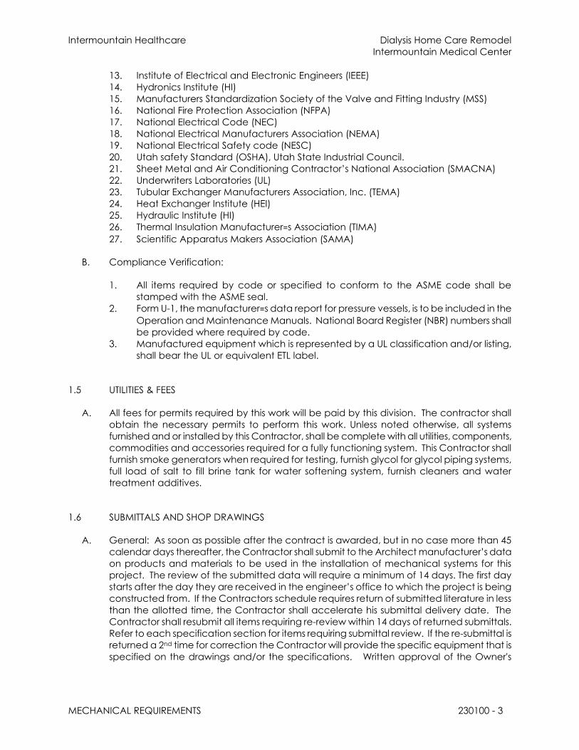
Intermountain Healthcare Dialysis Home Care Remodel
Intermountain Medical Center
MECHANICAL REQUIREMENTS 230100 - 3
13. Institute of Electrical and Electronic Engineers (IEEE)
14. Hydronics Institute (HI)
15. Manufacturers Standardization Society of the Valve and Fitting Industry (MSS)
16. National Fire Protection Association (NFPA)
17. National Electrical Code (NEC)
18. National Electrical Manufacturers Association (NEMA)
19. National Electrical Safety code (NESC)
20. Utah safety Standard (OSHA), Utah State Industrial Council.
21. Sheet Metal and Air Conditioning Contractor’s National Association (SMACNA)
22. Underwriters Laboratories (UL)
23. Tubular Exchanger Manufacturers Association, Inc. (TEMA)
24. Heat Exchanger Institute (HEI)
25. Hydraulic Institute (HI)
26. Thermal Insulation Manufacturer=s Association (TIMA)
27. Scientific Apparatus Makers Association (SAMA)
B. Compliance Verification:
1. All items required by code or specified to conform to the ASME code shall be
stamped with the ASME seal.
2. Form U-1, the manufacturer=s data report for pressure vessels, is to be included in the
Operation and Maintenance Manuals. National Board Register (NBR) numbers shall
be provided where required by code.
3. Manufactured equipment which is represented by a UL classification and/or listing,
shall bear the UL or equivalent ETL label.
1.5 UTILITIES & FEES
A. All fees for permits required by this work will be paid by this division. The contractor shall
obtain the necessary permits to perform this work. Unless noted otherwise, all systems
furnished and or installed by this Contractor, shall be complete with all utilities, components,
commodities and accessories required for a fully functioning system. This Contractor shall
furnish smoke generators when required for testing, furnish glycol for glycol piping systems,
full load of salt to fill brine tank for water softening system, furnish cleaners and water
treatment additives.
1.6 SUBMITTALS AND SHOP DRAWINGS
A. General: As soon as possible after the contract is awarded, but in no case more than 45
calendar days thereafter, the Contractor shall submit to the Architect manufacturer’s data
on products and materials to be used in the installation of mechanical systems for this
project. The review of the submitted data will require a minimum of 14 days. The first day
starts after the day they are received in the engineer’s office to which the project is being
constructed from. If the Contractors schedule requires return of submitted literature in less
than the allotted time, the Contractor shall accelerate his submittal delivery date. The
Contractor shall resubmit all items requiring re-review within 14 days of returned submittals.
Refer to each specification section for items requiring submittal review. If the re-submittal is
returned a 2nd time for correction the Contractor will provide the specific equipment that is
specified on the drawings and/or the specifications. Written approval of the Owner's

Intermountain Healthcare Dialysis Home Care Remodel
Intermountain Medical Center
MECHANICAL REQUIREMENTS 230100 - 4
Representative shall be obtained before installing any such equipment or materials for the
project.
B. Review by the Owner's Representative is for general conformance of the submitted
equipment to the project specification. In no way does such review relieve this Contractor
of his obligation to furnish equipment and materials that comply in detail to the
specification nor does it relieve the Contractor of his obligation to determine actual field
dimensions and conditions that may affect his work. Regardless of any items overlooked by
the submittal review, the requirements of the contract drawings and specifications must be
followed and are not waived or superseded in any way by the review.
C. By description, catalog number, and manufacturer's names, standards of quality have
been established by the Architect and the Engineer for certain manufactured equipment
items and specialties that are to be furnished by this Division. Alternate products and
equipment may be proposed for use only if specifically named in the specifications or if
given written prior approval in published addenda. Design equipment is the equipment
listed on the drawings or if not listed on the drawings is the equipment first named in the
specifications.
D. If the Engineer is required to do additional design work to incorporate changes caused by
submitting equipment or products, different than the design equipment specified, as
defined above, the contractor shall reimburse the engineer for additional time and
expenses at the engineer’s current, recognized, hourly rates.
E. Submittal Format:
1. Electronic Submittal Format: Identify and incorporate information in each electronic
submittal file as follows:
a. All items shall be submitted at one time except automatic temperature control
drawings and seismic restraint drawings which may be submitted separately
within 120 days of the contract award date. Partial submittals will not be
reviewed until the complete submittal is received.
b. Submitted electronic file shall bear the Contractor's stamp, indicating that he
has checked all equipment being submitted; that each item will fit into the
available space with the accesses shown on the drawings; and, further, that
each item conforms to the capacity and quality standards given in the
contract documents.
c. Submitted electronic file shall clearly indicate performance, quality, and utility
requirements; shall show dimension and size of connection points; and shall
include derating factors that were applied for each item of equipment to
provide capacity at job site elevation. Temperature control submittals shall
include piping and wiring diagrams, sequence of operation and equipment.
Equipment must fit into the available space with allowance for operation,
maintenance, etc. Factory piped and wired equipment shall include shop
drawings for all internal wiring and piping furnished with the unit.
d. Submitted electronic file shall clearly show all required field install wiring, piping,
and accessory installations required by the Contractor to provide a complete
operating system.
e. Assemble complete submittal package into a single indexed file incorporating
submittal requirements of a single Specification Section and transmittal form
with links enabling navigation to each item.

Intermountain Healthcare Dialysis Home Care Remodel
Intermountain Medical Center
MECHANICAL REQUIREMENTS 230100 - 5
f. Name file with submittal number or other unique identifier, including revision
identifier.
g. Electronic file shall be completely electronically searchable or it will be
rejected.
h. Provide means for insertion to permanently record Contractor's review and
approval markings and action taken by:
1) Architect.
i. Transmittal Form for Electronic Submittals:
1) Use one of the following options acceptable to the Owner;
a) Software-generated form from electronic project management
software.
b) Electronic form.
2) The Electronic Submittal shall contain the following information:
a) Project name.
b) Date.
c) Name and address of Architect.
d) Name of Construction Manager.
e) Name of Contractor.
f) Name of firm or entity that prepared submittal.
g) Names of subcontractor, manufacturer, and supplier.
h) Category and type of submittal.
i) Submittal purpose and description.
j) Specification Section number and title.
k) Specification paragraph number or drawing designation and
generic name for each of multiple items.
l) Drawing number and detail references, as appropriate.
m) Location(s) where product is to be installed, as appropriate.
n) Related physical samples submitted directly.
o) Indication of full or partial submittal.
p) Transmittal number[, numbered consecutively].
q) Submittal and transmittal distribution record.
r) Other necessary identification.
s) Remarks.
j. Metadata: Include the following information as keywords in the electronic
submittal file metadata:
1) Project name.
2) Number and title of appropriate Specification Section.
3) Manufacturer name.
4) Product name.
1.7 DRAWINGS AND MEASUREMENTS
A. Construction Drawings: The contract document drawings show the general design,
arrangements, and extent of the system. In certain cases, the drawings may include details
that show more nearly exact locations and arrangements; however, the locations, as
shown diagrammatically, are to be regarded as general.

Intermountain Healthcare Dialysis Home Care Remodel
Intermountain Medical Center
MECHANICAL REQUIREMENTS 230100 - 6
B. It shall be the work of this Section to make such slight alterations as may be necessary to
make adjustable parts fit to fixed parts, leaving all complete and in proper shape when
done. All dimensions given on the drawings shall be verified as related to this work and
with the Architect's office before work is started.
C. This Section shall carefully study building sections, space, clearances, etc., and then
provide offsets in piping or ductwork as required to accommodate the building structure
without additional cost to the Owner. In any case and at any time during the construction
process, a change in location required by obstacles or the installation of other trades not
shown on the mechanical plans shall be made without charge.
D. The drawings shall not be scaled for roughing in measurements nor shall they be used as
shop drawings. Where drawings are required for these purposes or where drawings must be
made from field measurements, the Contractor shall take the necessary measurements
and prepare the drawings. Shop drawings of the various subcontractors shall be
coordinated to eliminate all interferences and to provide sufficient space for the
installation of all equipment, piping, ductwork, etc.
E. The drawings and specifications have been prepared to supplement each other and they
shall be interpreted as an integral unit with items shown on one and not the other being
furnished and installed as though shown and called out on both.
F. Coordination Drawings: The contractor shall provide coordination drawings for mechanical
rooms, fan rooms, equipment rooms, and congested areas to eliminate conflicts with
equipment, piping, or work of other trades. The drawings shall be a minimum scale of 1/4
inch= 1 foot and of such detail as may be required by the Engineer to fully illustrate the
work. These drawings shall include all piping, conduit, valves, equipment, and ductwork.
G. Sheet-metal shop drawings will be required for all ductwork in the entire building. These
drawings will show all ductwork in the entire building and shall be coordinated with
architectural, structural and electrical portions of the project. The contractor shall
specifically obtain copies of the structural shop drawings and shall coordinate the
ductwork shop drawings with approved structural members. These drawings shall be
submitted to the engineer for review prior to any fabrication. The contractor is responsible
for all modifications necessary to accommodate duct installation within the structural,
architectural and electrical restrictions. These drawings, once reviewed by the engineer,
will be made available to all mechanical, electrical, and fire sprinkler subcontractors to
coordinate installation of their work.
1.8 CONTRACTOR'S USE OF BUILDING EQUIPMENT
A. The Contractor may use equipment such as electric motors, fans, heat exchangers, filters,
etc., with the written permission of the Owner. As each piece of equipment is used (such as
electric motors and fans), maintenance procedures approved by the manufacturer are to
be followed. A careful record is to be kept of the length of the time the equipment is used,
maintenance procedures followed, and any difficulty encountered. The record is to be
submitted to the Owner upon acceptance. All fan belts and filter media (such as bearings)
shall be carefully inspected just prior to acceptance. Any excessive wear noted shall
require replacement. New filter media shall be installed in air handlers at the time systems
are turned over to the owner.

Intermountain Healthcare Dialysis Home Care Remodel
Intermountain Medical Center
MECHANICAL REQUIREMENTS 230100 - 7
1.9 EXISTING CONDITIONS
A. The Contractor shall carefully examine all existing conditions that might affect the
mechanical system and shall compare these conditions with all drawings and
specifications for work included under this contract. He shall, at such time, ascertain and
check all conditions that may affect his work. No allowance shall subsequently be made in
his behalf for an extra expense incurred as a result of his failure or neglect to make such
examination. This Contractor shall include in his bid proposal all necessary allowances to
repair or replace any item that will remain or will be removed, and any item that will be
damaged or destroyed by new construction.
B. The Contractor shall remove all abandoned piping, etc., required by new construction and
cap or plug openings. No capping, etc., shall be exposed in occupied areas. All openings
of items removed shall be sealed to match adjacent surfaces.
C. The Contractor shall verify the exact location of all existing services, utilities, piping, etc.,
and make connections to existing systems as required or as shown on the drawings. The
exact location of each utility line, together with size and elevation, shall be established
before any on-site lines are installed. Should elevation or size of existing main utility lines
make connections to them impossible as shown on drawings, then notification of such shall
immediately be given to the Owners Representative for a decision.
1.10 EQUIPMENT CAPACITIES
A. Capacities shown for equipment in the specifications and on the drawings are the
minimum acceptable. No equipment shall be considered as an alternate that has
capacities or performance less than that of design equipment.
B. All equipment shall give the specified capacity and performance at the job-site elevation.
Manufacturers' standard ratings shall be adjusted accordingly. All capacities and
performances listed on drawings or in specifications are for job-site conditions.
1.11 SEISMIC REQUIREMENTS FOR EQUIPMENT
A. All equipment shall be furnished structurally adequate to withstand seismic forces as
outlined in the International Building Code. Refer to section Mechanical Vibration Controls
and Seismic Restraints. Equipment bases shall be designed for direct attachment of seismic
snubbers and/or seismic anchors.
1.12 COOPERATION WITH OTHER TRADES
A. The Contractor shall refer to other drawings and parts of this specification that cover work
of other trades that is carried on in conjunction with the mechanical work such that all work
can proceed without interference resulting from lack of coordination.
B. The Contractor shall properly size and locate all openings, chases, sleeves, equipment
bases, and accesses. He shall provide accurate wiring diagrams to the Electrical
Contractor for all equipment furnished under this Division.

Intermountain Healthcare Dialysis Home Care Remodel
Intermountain Medical Center
MECHANICAL REQUIREMENTS 230100 - 8
C. The ceiling cavity must be carefully reviewed and coordinated with all trades. In the event
of conflict, the installation of the mechanical equipment and piping shall be in the
following order: plumbing, waste, and soil lines; supply, return, and exhaust ductwork;
water piping; medical gases; fire protection piping; and pneumatic control piping.
D. The mechanical Contractor shall insure that the installation of all piping, ducts and
equipment is in compliance with Articles 110-16 and 384-4 of the National Electrical Code
relative to proper clearances in front of and over all electrical panels and equipment. No
piping or ductwork will be allowed to run over electrical panel.
1.13 RESPONSIBILITY OF CONTRACTOR
A. The Contractor is responsible for the installation of a satisfactory piece of work in
accordance with the true intent of the drawings and specifications. He shall provide, as a
part of his work and without expense, all incidental items required even though these items
are not particularly specified or indicated. The installation shall be made so that its several
component parts will function together as a workable system and shall be left with all
equipment properly adjusted and in working order. The Contractor shall familiarize the
Owner's Representative with maintenance and lubrication instructions as prepared by the
Contractor and shall explain and fully instruct him relative to operating, servicing, and
maintenance of them.
B. If a conflict arises between the drawings and the specifications the most stringent
procedure/action shall be followed. A clarification to the engineer will help to determine
the course of action to be taken. If a conflict arises between specification sections the
engineer will determine which course of action is to be followed.
1.14 PIPE AND DUCT OPENINGS AND EQUIPMENT RECESSES
A. Pipe and duct chases, openings, and equipment recesses shall be provided by others only
if shown on architectural or structural drawings. All openings for the mechanical work,
except where plans and specifications indicate otherwise, shall be provided as work of this
Division. Include openings information with coordination drawings.
B. Whether chases, recesses, and openings are provided as work of this Division or by others,
this Contractor shall supervise their construction and be responsible for the correct size and
location even though detailed and dimensioned on the drawings. This Contractor shall
pay for all necessary cutting, repairing, and finishing if any are left out or incorrectly made.
All necessary openings thru existing walls, ceilings, floors, roofs, etc. shall be provided by this
Contractor unless indicated otherwise by the drawing and/or specifications.
1.15 UNFIT OR DAMAGED WORK
A. Any part of this installation that fails, is unfit, or becomes damaged during construction, shall
be replaced or otherwise made good. The cost of such remedy shall be the responsibility
of this Division.
Intermountain Healthcare Dialysis Home Care Remodel
Intermountain Medical Center
MECHANICAL REQUIREMENTS 230100 - 9
1.16 WORKMANSHIP
A. Workmanship shall be the best quality of its kind for the respective industries, trades, crafts,
and practices, and shall be acceptable in every respect to the Owner's representative.
Nothing contained herein shall relieve the Contractor from making good and perfect work
in all details in construction.
1.17 SAFETY REGULATION
A. The Contractor shall comply with all local, Federal, and OSHA safety requirements in
performance with this work. (See General Conditions). This Contractor shall be required to
provide equipment, supervision, construction, procedures, and all other necessary items to
assure safety to life and property.
1.18 ELECTRICAL SERVICES
A. All equipment control wiring and all automatic temperature control wiring including all
necessary contacts, relays, and interlocks, whether low or line voltage, except power
wiring, shall be furnished and installed as work of this Division unless shown to be furnished
by Division 26. All such wiring shall be in conduit as required by electrical codes. Wiring in
the mechanical rooms, fans rooms and inaccessible ceilings and walls shall be installed in
conduit as well. Installation of any and all wiring done under Division 21, 22 and 23 shall be
in accordance with the requirements of Division 26, Electrical.
B. All equipment that requires an electrical connection shall be furnished so that it will operate
properly and deliver full capacity on the electrical service available.
C. Refer to the electrical control equipment and wiring shown on the diagrams. Any changes
or additions required by specific equipment furnished shall be the complete responsibility of
the Contractor furnishing the equipment.
D. The Mechanical Contractor must coordinate with the Electrical Contractor to insure that all
required components of control work are included and fully understood. No additional
cost shall accrue to the Owner as a result of lack of such coordination.
1.19 WORK, MATERIALS, AND QUALITY OF EQUIPMENT
A. Unless otherwise specified, all materials shall be new and of the best quality of their
respective kinds and all labor shall be done in a most thorough and workmanlike manner.
B. Products or equipment of any of the manufacturers cited herein or any of the products
approved by the Addenda may be used. However, where lists of products are cited
herein, the one first listed in the design equipment used in drawings and schedules to
establish size, quality, function, and capacity standards. If other than design equipment is
used, it shall be carefully checked for access to equipment, electrical and control
requirements, valving, and piping. Should changes or additions occur in piping, valving,
electrical work, etc., or if the work of other Contractors would be revised by the alternate
equipment, the cost of all changes shall be borne as work of this Division.
Intermountain Healthcare Dialysis Home Care Remodel
Intermountain Medical Center
MECHANICAL REQUIREMENTS 230100 - 10
C. The Execution portions of the specifications specify what products and materials may be
used. Any products listed in the Product section of the specification that are not listed in
the Execution portion of the specification may not be used without written approval by the
Engineer.
D. The access to equipment shown on the drawings is the minimum acceptable space
requirements. No equipment that reduces or restricts accessibility to this or any other
equipment will be considered.
E. All major items of equipment are specified in the equipment schedules on the drawings or
in these specifications and shall be furnished complete with all accessories normally
supplied with the catalog item listed and all other accessories necessary for a complete
and satisfactory installation.
F. All welders shall be certified in accordance with Section IX of the ASME Boiler and Pressure
Vessel Code, latest Edition.
1.20 PROTECTION AGAINST WEATHER AND STORING OF MATERIALS
A. All equipment and materials shall be properly stored and protected against moisture, dust,
and wind. Coverings or other protection shall be used on all items that may be damaged
or rusted or may have performance impaired by adverse weather or moisture conditions.
Damage or defect developing before acceptance of the work shall be made good at the
Contractor's expense.
B. All open duct and pipe openings shall be adequately covered at all times.
1.21 INSTALLATION CHECK
A. An experienced, competent, and authorized representative of the manufacturer or
supplier of each item of equipment indicated in the equipment schedule and the seismic
supplier shall visit the site of the work and inspect, check, adjust if necessary, and approve
the equipment installation. In each case, the equipment supplier's representative shall be
present when the equipment is placed in operation. The equipment supplier's
representative shall revisit the job site as often as necessary until all trouble is corrected and
the equipment installation and operation is satisfactory to the Engineer.
B. Each equipment supplier's representative shall furnish to the Owner, through the Engineer, a
written report certifying that the equipment (1) has been properly installed and lubricated;
(2) is in accurate alignment; (3) is free from any undue stress imposed by connecting piping
or anchor bolts; and, (4) has been operated under full load conditions and that it operated
satisfactorily.
C. All costs for this work shall be included in the prices quoted by equipment suppliers.
1.22 EQUIPMENT LUBRICATION
A. The Contractor shall properly lubricate all pieces of equipment before turning the building
over to the Owner. A linen tag shall be attached to each piece of equipment, showing

Intermountain Healthcare Dialysis Home Care Remodel
Intermountain Medical Center
MECHANICAL REQUIREMENTS 230100 - 11
the date of lubrication and the lubricant used. No equipment shall be started until it is
properly lubricated.
B. Necessary time shall be spent with the Owner's Representative to thoroughly familiarize him
with all necessary lubrications and maintenance that will be required of him.
C. Detergent oil as used for automotive purposes shall not be used for this work.
1.23 CUTTING AND PATCHING
A. No cutting or drilling in structural members shall be done without written approval of the
Architect. The work shall be carefully laid out in advance, and cutting, channeling,
chasing, or drilling of floors, walls, partitions, ceilings, or other surfaces necessary for the
mechanical work shall be carefully done. Any damage to building, piping, or equipment
shall be repaired by professional plasterers, masons, concrete workers, etc., and all such
work shall be paid for as work of this Division.
B. When concrete, grading, etc., is disturbed, it shall be restored to original condition as
described in the applicable Division of this Specification.
1.24 EXCAVATION AND BACKFILLING
A. All necessary excavations and backfilling for the Mechanical phase of this project shall be
provided as work of this Division. Trenches for all underground pipelines shall be excavated
to the required depths. The bottom of trenches shall be compacted hard and graded to
obtain required fall. Backfill shall be placed in horizontal layers, not exceeding 12 inches in
thickness, and properly moistened. Each layer shall be compacted, by suitable
equipment, to a density of not less than 95 percent as determined by ASTM D-1557. After
pipelines have been tested, inspected, and approved, the trench shall be backfilled with
selected material. Excess earth shall be hauled from the job site. Fill materials approved by
the Architect shall be provided as work of this Division.
B. No trenches shall be cut near or under any footings without consultation first with the
Architect's office. Any trenches or excavations more than 30 inches deep shall be tapered,
shored, covered, or otherwise made absolutely safe so that no vehicle or persons can be
injured by falling into such excavations, or in any way be harmed by cave-ins, shifting earth,
rolling rocks, or by drowning. This protection shall be extended to all persons approaching
excavation related to this work whether or not such persons are authorized to be in the
vicinity of the construction.
1.25 ACCESS
A. Provide access doors in walls, ceilings and floors by this division unless otherwise noted. For
access to mechanical equipment such as valves, dampers, VAV boxes, fans, controls, etc.
Refer to Division 8 for door specifications. All access doors shall be 24" x 24" unless otherwise
indicated or required. Coordinate location of doors with the Architect prior to installation. .
If doors are not specified in Division 8, provide the following: Doors in ceilings and wall shall
be equal to JR Smith No. 4760 bonderized and painted. Doors in tile walls shall be equal to
JR Smith No. 4730 chrome plated. Doors in floors shall be equal to JR Smith No. 4910
Intermountain Healthcare Dialysis Home Care Remodel
Intermountain Medical Center
MECHANICAL REQUIREMENTS 230100 - 12
B. Valves: Valve must be installed in locations where access is readily available. If access is
compromised, as judged by the Mechanical Engineer, these valves shall be relocated
where directed at the Contractors expense.
C. Equipment: Equipment must be installed in locations and orientations so that access to all
components requiring service or maintenance will not be compromised. If access is
compromised, as judged by the Mechanical Engineer, the contractor shall modify the
installation as directed by the Engineer at the Contractors expense.
D. It is the responsibility of this division to install terminal boxes, valves and all other equipment
and devices so they can be accessed. If any equipment or devices are installed so they
cannot be accessed on a ladder a catwalk and ladder system shall be installed above the
ceiling to access and service this equipment.
1.26 CONCRETE BASES AND INSERTS
A. Bases: The concrete bases shall be provided and installed as work by this divsion. This
Division shall be responsible for the proper size and location of bases and shall furnish all
required anchor bolts and sleeves with templates to be installed as work of Division 3,
Concrete.
B. All floor-mounted mechanical equipment shall be set on 6-inch high concrete bases, unless
otherwise noted or shown on drawings. Such bases shall extend 6 inches beyond
equipment or mounting rails on all sides or as shown on the drawings and shall have a 1-
inch beveled edge all around.
C. Inserts: Where slotted or other types of inserts required for this work are to be cast into
concrete, they shall be furnished as work of this Division
D. Concrete inserts and pipe support systems shall be equal to Unistrut P3200 series for all
piping where more than one pipe is suspended at a common location. Spacing of the
inserts shall match the size and type of pipe and of ductwork being supported. The Unistrut
insert and pipe support system shall include all inserts, vertical supports, horizontal support
members, clamps, hangers, rollers, bolts, nuts, and any other accessory items for a
complete pipe-supporting system.
1.27 CLEANING AND PAINTING
A. Cleaning: After all tests and adjustments have been made and all systems pronounced
satisfactory for permanent operation, this Contractor shall clean all exposed piping,
ductwork, insulated members, fixture, and equipment installed under this Section and leave
them ready for painting. He shall refinish any damaged finish and leave everything in
proper working order. The Contractor shall remove all stains or grease marks on walls,
floors, glass, hardware, fixtures, or elsewhere, caused by his workman or for which he is
responsible. He shall remove all stickers on plumbing fixtures, do all required patching up
and repair all work of others damaged by this division of the work, and leave the premises
in a clean and orderly condition.
B. Painting: Painting of exposed pipe, insulated pipe, ducts, or equipment is work of Division 9,
Painting.

Intermountain Healthcare Dialysis Home Care Remodel
Intermountain Medical Center
MECHANICAL REQUIREMENTS 230100 - 13
C. Mechanical Contractor: All equipment which is to be furnished in factory prefinished
conditions by the mechanical Contractor shall be left without mark, scratch, or impairment
to finish upon completion of job. Any necessary refinishing to match original shall be done.
Do not paint over nameplates, serial numbers, or other identifying marks.
D. Removal of Debris, Etc: Upon completion of this division of the work, remove all surplus
material and rubbish resulting from this work, and leave the premises in a clean and orderly
condition.
1.28 CONTRACT COMPLETION
A. Incomplete and Unacceptable Work: If additional site visits or design work is required by
the Engineer or Architect because of the use of incomplete or unacceptable work by the
Contractor, then the Contractor shall reimburse the Engineer and Architect for all
additional time and expenses involved.
B. Maintenance Instructions: The Contractor shall furnish the Owner complete printed and
illustrated operating and maintenance instructions covering all units of mechanical
equipment, together with parts lists.
C. Instructions To Owner's Representatives: In addition to any detailed instructions called for,
the mechanical Contractor must provide, without expense to the Owner, competent
instructors to train the Owner's representatives who will be in charge of the apparatus and
equipment, in the care, adjustment, and operation of all parts on the heating, air
conditioning, ventilating, plumbing, fire protection, and automatic temperature control
equipment. Instruction dates shall be scheduled at time of final inspection. A written
report specifying times, dates, and name of personnel instructed shall be forwarded to the
Architect. A minimum of four 8-hour instruction periods shall be provided. The instruction
periods will be broken down to shorter periods when requested by the Owner. The total
instruction hours shall not reduced. The ATC Contractor shall provide 4 hours of instructions.
The remaining hours shall be divided between the mechanical and sheet metal
Contractor.
D. Guarantee: By the acceptance of any contract award for the work herein described or
shown on the drawings, the Contractor assumes the full responsibility imposed by the
guarantee as set forth herein and in the General Conditions, and should protect himself
through proper guarantees from equipment and special equipment Contractors and from
subcontractors as their interests may appear.
E. The guarantee so assumed by the Contractor and as work of this Section is as follows:
1. That the entire mechanical system, including plumbing, heating, and air-conditioning
system shall be quiet in operation.
2. That the circulation of water shall be complete and even.
3. That all pipes, conduit, and connections shall be perfectly free from foreign matter
and pockets and that all other obstructions to the free passage of air, water, liquid,
sewage, and vent shall be removed.
4. That he shall make promptly and free of charge, upon notice from the Owner, any
necessary repairs due to defective workmanship or materials that may occur during
a period of one year from date of Substantial Completion.

Intermountain Healthcare Dialysis Home Care Remodel
Intermountain Medical Center
MECHANICAL REQUIREMENTS 230100 - 14
5. That all specialties, mechanical, and patent devices incorporated in these systems
shall be adjusted in a manner that each shall develop its maximum efficiency in the
operation of the system; i.e., diffusers shall deliver the designed amount of air shown
on drawings, thermostats shall operate to the specified limits, etc.
6. All equipment and the complete mechanical, ductwork, piping and plumbing
systems shall be guaranteed for a period of one year from the date of the Architect's
Certificate of Substantial Completion, this includes all mechanical, ductwork, piping
and plumbing equipment and products and is not limited to boiler, chillers, coils, fans,
filters etc. Any equipment supplier not willing to comply with this guarantee period
shall not submit a bid price for this project. The Contractor shall be responsible for a
100-percent guarantee for the system and all items of equipment for this period. If
the contractor needs to provide temporary heating or cooling to the building and or
needs to insure systems are installed properly and or to meet the project schedule
the guaranteed of all systems and equipment shall be as indicated above, on year
from the date of the Architect’s Certificate of Substantial Completion.
7. All filters used during construction shall be replaced just before equipment is turned
over to the Owner, and all required equipment and parts shall be oiled. Any worn
parts shall also be replaced.
8. If any systems or equipment is used for temporary heating or cooling the systems shall
be protected so they remain clean. I.e. if the ductwork systems are used temporary
filters and a filter holder (not duct-taped to ducts or grilles) shall be installed to insure
the systems and the equipment remain clean.
1.29 CURBS
A. Unless otherwise noted in these specifications or on the documents all roof curbs for all
equipment are to be provided by Division 22 and 23.
1.30 TEST RUN
A. The Mechanical Contractor shall operate the mechanical system for a minimum of 30 days
to prove the operation of the system.
1.31 EQUIPMENT STARTUP AND CHECKOUT:
A. Each major piece of equipment shall be started and checked out by an authorized
representative of the equipment manufacturer. A certificate indicating the equipment is
operating to the satisfaction of the manufacturer shall be provided and shall be included in
the commissioning report.
B. This contractor shall coordinate commissioning procedures and activities with the
commissioning agent.
1.32 DEMOLITION
A. General: Demolish and remove existing construction only to the extent required by new
construction and as indicated. Use methods required to complete the Work within
limitations of governing regulations and as follows:

Intermountain Healthcare Dialysis Home Care Remodel
Intermountain Medical Center
MECHANICAL REQUIREMENTS 230100 - 15
B. Proceed with demolition systematically, from higher to lower level. Complete selective
demolition operations above each floor or tier before disturbing supporting members on
the next lower level.
C. Neatly cut openings and holes plumb, square, and true to dimensions required. Use cutting
methods least likely to damage construction to remain or adjoining construction. Use hand
tools or small power tools designed for sawing or grinding, not hammering and chopping,
to minimize disturbance of adjacent surfaces. Temporarily cover openings to remain.
D. Cut or drill from the exposed or finished side into concealed surfaces to avoid marring
existing finished surfaces.
E. Do not use cutting torches until work area is cleared of flammable materials. At concealed
spaces, such as duct and pipe interiors, verify condition and contents of hidden space
before starting flame-cutting operations. Maintain portable fire-suppression devices during
flame-cutting operations.
F. Maintain adequate ventilation when using cutting torches.
G. Remove decayed, vermin-infested, or otherwise dangerous or unsuitable materials and
promptly dispose of off-site.
H. Remove structural framing members and lower to ground by method suitable to avoid free
fall and to prevent ground impact or dust generation.
I. Locate selective demolition equipment and remove debris and materials so as not to
impose excessive loads on supporting walls, floors, or framing.
J. Dispose of demolished items and materials promptly.
K. Return elements of construction and surfaces that are to remain to condition existing
before selective demolition operations began.
L. Existing Facilities: Comply with building manager's requirements for using and protecting
elevators, stairs, walkways, loading docks, building entries, and other building facilities
during selective demolition operations.
M. Concrete: Demolish in sections. Cut concrete full depth at junctures with construction to
remain and at regular intervals, using power-driven saw, then remove concrete between
saw cuts.
N. Masonry: Demolish in small sections. Cut masonry at junctures with construction to remain,
using power-driven saw, and then remove masonry between saw cuts.
O. Concrete Slabs-on-Grade: Saw-cut perimeter of area to be demolished, then break up
and remove.
P. Air-Conditioning Equipment: Remove equipment without releasing refrigerants.
END OF SECTION 230100

Intermountain Healthcare Dialysis Home Care Remodel
Intermountain Medical Center
TEMPORARY USE OF EQUIPMENT AND SYSTEMS 230150 - 1
SECTION 230150 - TEMPORARY USE OF EQUIPMENT AND SYSTEMS
PART 1 - GENERAL
1.1 SUMMARY
A. This section includes requirements for temporary us of equipment and systems and
any other items that are used during the construction of the project.
1.2 EQUIPMENT OR SYSTEMS NEEDED TO OPERATE BEFORE CONTRACT COMPLETION
A. If the contractor needs to provide temporary heating or cooling to the building and
or needs to insure systems are installed properly for start up and or to meet the
project schedule the guaranteed of all systems and equipment shall be for one year
from the date of the Architect’s Certificate of Substantial Completion.
B. All equipment and the complete mechanical, ductwork, piping and plumbing
systems shall be guaranteed for a period of one year from the date of the Architect's
Certificate of Substantial Completion, this includes all mechanical, ductwork, piping
and plumbing equipment and products and is not limited to boiler, chillers, coils, fans,
filters etc. Any contractor or equipment supplier who is not willing to comply with this
guarantee period shall not submit a bid price for this project. The Contractor shall be
responsible for a 100-percent guarantee for the systems and all items of equipment
for this period.
C. All filters used during construction shall be replaced just before equipment is turned
over to the Owner, and all required equipment and parts shall be oiled. Any worn
parts shall also be replaced.
D. If any systems or equipment is used for temporary heating or cooling the systems shall
be protected so they remain clean. I.e. if the ductwork systems are used temporary
filters and a filter holder (not duct-taped to ducts or grilles) shall be installed to insure
the systems and the equipment remain clean. All return air openings shall be
protected with a metal filter frame and filters.
1.3 TEMPORARY EQUIPMENT OR SYSTEM SUBMITTALS
A. If it is determined by the project or contractor that equipment or systems are needed
to operate to provide heating, cooling or other needed services this division shall
submit a document indicating what measures will be taken to insure the safe and
proper operation of the equipment, systems and personal associated with the
operation, this document shall be submitted to the engineer for approval. This plan
shall show connections of equipment, utility hookups (if required) staging areas etc.
1.4 QUALITY ASSURANCE
A. Electric Service: Comply with NECA, NEMA, and UL standards and regulations for
temporary electric service. Install service to comply with NFPA 70.

Intermountain Healthcare Dialysis Home Care Remodel
Intermountain Medical Center
TEMPORARY USE OF EQUIPMENT AND SYSTEMS 230150 - 2
B. Tests and Inspections: Arrange for authorities having jurisdiction to test and inspect
each temporary utility before use. Obtain required certifications and permits.
C. Accessible Temporary Egress: Comply with applicable provisions in the U.S.
Architectural & Transportation Barriers Compliance Board's ADA-ABA Accessibility
Guidelines.
D. SMACNA: The latest standard from SSMACNA shall apply.
1.5 PROJECT CONDITIONS
A. Temporary Use of equipment or systems: Engage installer of each permanent service
to assume responsibility for operation, maintenance, and protection of each
permanent service during its use until the facility has been accepted by the owner
regardless of previously assigned responsibilities.
PART 2 - PRODUCTS
2.1 EQUIPMENT
A. Fire Extinguishers: Portable, UL rated; with class and extinguishing agent as required
by locations and classes of fire exposures.
B. HVAC Equipment: Unless Owner authorizes use of permanent HVAC system, provide
vented, self-contained, liquid-propane-gas or fuel-oil heaters and cooling units if
required with individual space thermostatic control.
1. Use of gasoline-burning space heaters, open-flame heaters, or salamander-type
heating units is prohibited.
2. Heating Units: Listed and labeled for type of fuel being consumed, by a testing
agency acceptable to authorities having jurisdiction, and marked for intended
use.
3. Permanent HVAC System: If Owner authorizes use of permanent HVAC system for
temporary use during construction, provide filters with MERV of 8 at each return
air opening in system and remove at end of construction. These filters are to be
installed in a filter housing frame and are not to be duct taped. Clean HVAC
system as required in Division 01 Section "Closeout Procedures.
PART 3 - EXECUTION
3.1 INSTALLATION, GENERAL
A. Locate equipment where they will serve Project adequately and result in minimum
interference with performance of the Work. Relocate and modify equipment and
systems as required by progress of the Work.
1. Locate equipment to limit site disturbance as specified in Division 01 Section
"Summary."
Intermountain Healthcare Dialysis Home Care Remodel
Intermountain Medical Center
TEMPORARY USE OF EQUIPMENT AND SYSTEMS 230150 - 3
3.2 TEMPORARY UTILITY INSTALLATION
A. General: Install temporary service or connect to existing service.
1. Arrange with utility company, Owner, and existing users for time when service can
be interrupted, if necessary, to make connections for temporary services.
B. Water Service: Install water service and distribution piping in sizes and pressures
adequate for construction.
C. Heating and Cooling: Provide temporary heating and cooling required by
construction activities for curing or drying of completed installations or for protecting
installed construction from adverse effects of low temperatures or high humidity.
Select equipment that will not have a harmful effect on completed installations or
elements being installed.
D. Ventilation and Humidity Control: Provide temporary ventilation required by
construction activities for curing or drying of completed installations or for protecting
installed construction from adverse effects of high humidity. Select equipment that
will not have a harmful effect on completed installations or elements being installed.
Coordinate ventilation requirements to produce ambient condition required and
minimize energy consumption.
3.3 OPERATION, TERMINATION, AND REMOVAL
A. Maintenance: Maintain equipment and systems in good operating condition until
removal.
1. Maintain operation of temporary enclosures, heating, cooling, humidity control,
ventilation, and similar equipment and systems on a 24-hour basis where required
to achieve indicated results and to avoid possibility of damage.
B. Termination and Removal: Remove each temporary facility or equipment when
need for its service has ended, when it has been replaced by authorized use of a
permanent facility, or no later than Substantial Completion. Complete or, if
necessary, restore permanent construction that may have been delayed because of
interference with temporary facility. Repair damaged Work, clean exposed surfaces,
and replace construction that cannot be satisfactorily repaired.
1. Materials equipment that constitute temporary equipment are property of
Contractor.
2. At Substantial Completion, repair, renovate, and clean permanent equipment
and systems used during construction period. Comply with final cleaning
requirements specified in Division 01 Section "Closeout Procedures."

Intermountain Healthcare Dialysis Home Care Remodel
Intermountain Medical Center
TEMPORARY USE OF EQUIPMENT AND SYSTEMS 230150 - 4
3.4 EQUIPMENT STARTUP AND CHECKOUT:
A. Each major piece of equipment shall be started and checked out by an authorized
representative of the equipment manufacturer at substantial completion. A
certificate indicating the equipment is operating to the satisfaction of the
manufacturer shall be provided and shall be included in the commissioning report.
END OF SECTION 230150

Intermountain Healthcare Dialysis Home Care Remodel
Intermountain Medical Center
COMMON WORK RESULTS FOR HVAC 230500 - 1
SECTION 230500 - COMMON WORK RESULTS FOR HVAC
PART 1 - GENERAL
1.1 RELATED DOCUMENTS
A. Drawings and general provisions of the Contract, including General and
Supplementary Conditions and Division 01 Specification Sections, apply to this Section.
1.2 SUMMARY
A. This Section includes the following:
1. Piping materials and installation instructions common to most piping systems.
2. Transition fittings.
3. Dielectric fittings.
4. Mechanical sleeve seals.
5. Sleeves.
6. Escutcheons.
7. Grout.
8. Equipment installation requirements common to equipment sections.
9. Painting and finishing.
10. Concrete bases.
11. Supports and anchorages.
12. Link-Seal
1.3 DEFINITIONS
A. Finished Spaces: Spaces other than mechanical and electrical equipment rooms,
furred spaces, pipe and duct chases, unheated spaces immediately below roof,
spaces above ceilings, unexcavated spaces, and crawlspaces.
B. Exposed, Interior Installations: Exposed to view indoors. Examples include finished
occupied spaces, mechanical equipment rooms, accessible pipe shafts, accessible
plumbing chases, and accessible tunnels.
C. Exposed, Exterior Installations: Exposed to view outdoors or subject to outdoor ambient
temperatures and weather conditions. Examples include rooftop locations.
D. Concealed, Interior Installations: Concealed from view and protected from physical
contact by building occupants. Examples include above ceilings and chases.
E. Concealed, Exterior Installations: Concealed from view and protected from weather
conditions and physical contact by building occupants but subject to outdoor ambient
temperatures. Examples include installations within unheated shelters.
F. The following are industry abbreviations for plastic materials:

Intermountain Healthcare Dialysis Home Care Remodel
Intermountain Medical Center
COMMON WORK RESULTS FOR HVAC 230500 - 2
1. CPVC: Chlorinated polyvinyl chloride plastic.
2. PVC: Polyvinyl chloride plastic.
G. The following are industry abbreviations for rubber materials:
1. EPDM: Ethylene-propylene-diene terpolymer rubber.
2. NBR: Acrylonitrile-butadiene rubber.
1.4 SUBMITTALS
A. Product Data: For the following:
1. Transition fittings.
2. Dielectric fittings.
3. Mechanical sleeve seals.
4. Escutcheons.
B. Welding certificates.
1.5 QUALITY ASSURANCE
A. Steel Support Welding: Qualify processes and operators according to AWS D1.1,
"Structural Welding Code--Steel."
B. Steel Pipe Welding: Qualify processes and operators according to ASME Boiler and
Pressure Vessel Code: Section IX, "Welding and Brazing Qualifications."
1. Comply with provisions in ASME B31 Series, "Code for Pressure Piping."
2. Certify that each welder has passed AWS qualification tests for welding processes
involved and that certification is current.
C. Electrical Characteristics for HVAC Equipment: Equipment of higher electrical
characteristics may be furnished provided such proposed equipment is approved in
writing and connecting electrical services, circuit breakers, and conduit sizes are
appropriately modified. If minimum energy ratings or efficiencies are specified,
equipment shall comply with requirements.
1.6 DELIVERY, STORAGE, AND HANDLING
A. Deliver pipes and tubes with factory-applied end caps. Maintain end caps through
shipping, storage, and handling to prevent pipe end damage and to prevent entrance
of dirt, debris, and moisture.
B. Store plastic pipes protected from direct sunlight. Support to prevent sagging and
bending.
1.7 COORDINATION
A. Arrange for pipe spaces, chases, slots, and openings in building structure during
progress of construction, to allow for HVAC installations.

Intermountain Healthcare Dialysis Home Care Remodel
Intermountain Medical Center
COMMON WORK RESULTS FOR HVAC 230500 - 3
B. Coordinate installation of required supporting devices and set sleeves in poured-in-
place concrete and other structural components as they are constructed.
C. Coordinate requirements for access panels and doors for HVAC items requiring access
that are concealed behind finished surfaces. Access panels and doors are specified in
Division 08 Section "Access Doors and Frames."
PART 2 - PRODUCTS
2.1 MANUFACTURERS
A. In other Part 2 articles where subparagraph titles below introduce lists, the following
requirements apply for product selection:
1. Manufacturers: Subject to compliance with requirements, provide products by
the manufacturers specified.
2.2 PIPE, TUBE, AND FITTINGS
A. Refer to individual Division 23 piping Sections for pipe, tube, and fitting materials and
joining methods.
B. Pipe Threads: ASME B1.20.1 for factory-threaded pipe and pipe fittings.
2.3 JOINING MATERIALS
A. Refer to individual Division 23 piping Sections for special joining materials not listed
below.
B. Pipe-Flange Gasket Materials: Suitable for chemical and thermal conditions of piping
system contents.
1. ASME B16.21, nonmetallic, flat, asbestos-free, 1/8-inch maximum thickness unless
thickness or specific material is indicated.
a. Full-Face Type: For flat-face, Class 125, cast-iron and cast-bronze flanges.
b. Narrow-Face Type: For raised-face, Class 250, cast-iron and steel flanges.
2. AWWA C110, rubber, flat face, 1/8 inch thick, unless otherwise indicated; and
full-face or ring type, unless otherwise indicated.
C. Flange Bolts and Nuts: ASME B18.2.1, carbon steel, unless otherwise indicated.
D. Solder Filler Metals: ASTM B 32, lead-free alloys. Include water-flushable flux according
to ASTM B 813.
E. Brazing Filler Metals: AWS A5.8, BCuP Series, copper-phosphorus alloys for general-duty
brazing, unless otherwise indicated; and AWS A5.8, BAg1, silver alloy for refrigerant
piping, unless otherwise indicated.

Intermountain Healthcare Dialysis Home Care Remodel
Intermountain Medical Center
COMMON WORK RESULTS FOR HVAC 230500 - 4
F. Welding Filler Metals: Comply with AWS D10.12 for welding materials appropriate for
wall thickness and chemical analysis of steel pipe being welded.
2.4 TRANSITION FITTINGS
A. Plastic-to-Metal Transition Fittings: CPVC and PVC one-piece fitting with manufacturer's
Schedule 80 equivalent dimensions; one end with threaded brass insert, and one
solvent-cement-joint end.
1. Manufacturers:
a. Eslon Thermoplastics.
B. Plastic-to-Metal Transition Adaptors: One-piece fitting with manufacturer's SDR 11
equivalent dimensions; one end with threaded brass insert, and one solvent-cement-
joint end.
1. Manufacturers:
a. Thompson Plastics, Inc.
2.5 DIELECTRIC FITTINGS
A. General: Assembly or fitting with insulating material isolating joined dissimilar metals, to
prevent galvanic action and stop corrosion.
B. Description: Combination of copper alloy and ferrous; threaded, solder, plain, and
weld-neck end types and matching piping system materials.
C. Insulating Material: Suitable for system fluid, pressure, and temperature.
D. Dielectric Unions: Factory-fabricated, union assembly, for 250-psig minimum working
pressure at 180 deg F.
E. Dielectric Flanges: Factory-fabricated, companion-flange assembly, for 150- or 300-
psig minimum working pressure as required to suit system pressures.
F. Dielectric-Flange Insulation Kits: Field-assembled, companion-flange assembly, full-face
or ring type. Components include neoprene or phenolic gasket, phenolic or
polyethylene bolt sleeves, phenolic washers, and steel backing washers.
1. Provide separate companion flanges and steel bolts and nuts for 150- or 300-psig
minimum working pressure as required to suit system pressures.
G. Dielectric Couplings: Galvanized-steel coupling with inert and noncorrosive,
thermoplastic lining; threaded ends; and 300-psig minimum working pressure at 225 deg
F.
H. Dielectric Nipples: Electroplated steel nipple with inert and noncorrosive, thermoplastic
lining; plain, threaded, or grooved ends; and 300-psig minimum working pressure at 225
deg F.
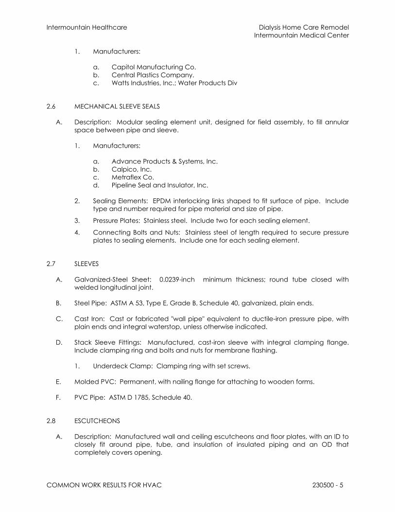
Intermountain Healthcare Dialysis Home Care Remodel
Intermountain Medical Center
COMMON WORK RESULTS FOR HVAC 230500 - 5
1. Manufacturers:
a. Capitol Manufacturing Co.
b. Central Plastics Company.
c. Watts Industries, Inc.; Water Products Div
2.6 MECHANICAL SLEEVE SEALS
A. Description: Modular sealing element unit, designed for field assembly, to fill annular
space between pipe and sleeve.
1. Manufacturers:
a. Advance Products & Systems, Inc.
b. Calpico, Inc.
c. Metraflex Co.
d. Pipeline Seal and Insulator, Inc.
2. Sealing Elements: EPDM interlocking links shaped to fit surface of pipe. Include
type and number required for pipe material and size of pipe.
3. Pressure Plates: Stainless steel. Include two for each sealing element.
4. Connecting Bolts and Nuts: Stainless steel of length required to secure pressure
plates to sealing elements. Include one for each sealing element.
2.7 SLEEVES
A. Galvanized-Steel Sheet: 0.0239-inch minimum thickness; round tube closed with
welded longitudinal joint.
B. Steel Pipe: ASTM A 53, Type E, Grade B, Schedule 40, galvanized, plain ends.
C. Cast Iron: Cast or fabricated "wall pipe" equivalent to ductile-iron pressure pipe, with
plain ends and integral waterstop, unless otherwise indicated.
D. Stack Sleeve Fittings: Manufactured, cast-iron sleeve with integral clamping flange.
Include clamping ring and bolts and nuts for membrane flashing.
1. Underdeck Clamp: Clamping ring with set screws.
E. Molded PVC: Permanent, with nailing flange for attaching to wooden forms.
F. PVC Pipe: ASTM D 1785, Schedule 40.
2.8 ESCUTCHEONS
A. Description: Manufactured wall and ceiling escutcheons and floor plates, with an ID to
closely fit around pipe, tube, and insulation of insulated piping and an OD that
completely covers opening.

Intermountain Healthcare Dialysis Home Care Remodel
Intermountain Medical Center
COMMON WORK RESULTS FOR HVAC 230500 - 6
B. One-Piece, Deep-Pattern Type: Deep-drawn, box-shaped brass with polished chrome-
plated finish.
C. One-Piece, Cast-Brass Type: With set screw.
1. Finish: Polished chrome-plated and rough brass.
D. One-Piece, Stamped-Steel Type: With set screw or spring clips and chrome-plated
finish.
E. Split-Plate, Stamped-Steel Type: With concealed hinge, set screw or spring clips, and
chrome-plated finish.
2.9 GROUT
A. Description: ASTM C 1107, Grade B, non-shrink and nonmetallic, dry hydraulic-cement
grout.
1. Characteristics: Post-hardening, volume-adjusting, non-staining, noncorrosive,
nongaseous, and recommended for interior and exterior applications.
2. Design Mix: 5000-psi, 28-day compressive strength.
3. Packaging: Premixed and factory packaged.
2.10 LINK-SEAL MODULAR SEAL PRESSURE PLATES
A. Link-Seal® modular seal pressure plates shall be molded of glass reinforced Nylon
Polymer with the following properties:
1. Izod Impact - Notched = 2.05ft-lb/in. per ASTM D-256
2. Flexural Strength @ Yield = 30,750 psi per ASTM D-790
3. Flexural Modulus = 1,124,000 psi per ASTM D-790
4. Elongation Break = 11.07% per ASTM D-638
5. Specific Gravity = 1.38 per ASTM D-792
B. Models LS200-275-300-315 shall incorporate the most current Link-Seal® Modular Seal
design modifications and shall include an integrally molded compression assist boss on
the top (bolt entry side) of the pressure plate, which permits increased compressive
loading of the rubber sealing element. Models 315-325-340-360-400-410-425-475-500-
525-575-600 shall incorporate an integral recess known as a “Hex Nut Interlock”
designed to accommodate commercially available fasteners to insure proper thread
engagement for the class and service of metal hardware. All pressure plates shall have
a permanent identification of the manufacturer’s name molded into it.
C. For fire service, pressure plates shall be steel with 2-part Zinc Dichromate Coating.
D. Link-Seal® Modular Seal Hardware: All fasteners shall be sized according to latest Link-
Seal® modular seal technical data. Bolts, flange hex nuts shall be:
1. 316 Stainless Steel per ASTM F593-95, with a 85,000 psi average tensile strength.

Intermountain Healthcare Dialysis Home Care Remodel
Intermountain Medical Center
COMMON WORK RESULTS FOR HVAC 230500 - 7
PART 3 - EXECUTION
3.1 PIPING SYSTEMS - COMMON REQUIREMENTS
A. Install piping according to the following requirements and Division 23 Sections
specifying piping systems.
B. Drawing plans, schematics, and diagrams indicate general location and arrangement
of piping systems. Indicated locations and arrangements were used to size pipe and
calculate friction loss, expansion, pump sizing, and other design considerations. Install
piping as indicated unless deviations to layout are approved on Coordination
Drawings.
C. Install piping in concealed locations, unless otherwise indicated and except in
equipment rooms and service areas.
D. Install piping indicated to be exposed and piping in equipment rooms and service
areas at right angles or parallel to building walls. Diagonal runs are prohibited unless
specifically indicated otherwise.
E. Install piping above accessible ceilings to allow sufficient space for ceiling panel
removal.
F. Install piping to permit valve servicing.
G. Install piping at indicated slopes.
H. Install piping free of sags and bends.
I. Install fittings for changes in direction and branch connections.
J. Install piping to allow application of insulation.
K. Select system components with pressure rating equal to or greater than system
operating pressure.
L. Install escutcheons for penetrations of walls, ceilings, and floors according to the
following:
1. New Piping:
a. Piping with Fitting or Sleeve Protruding from Wall: One-piece, deep-pattern
type.
b. Chrome-Plated Piping: One-piece, cast-brass type with polished chrome-
plated finish.
c. Insulated Piping: One-piece, stamped-steel type with spring clips.
d. Bare Piping at Wall and Floor Penetrations in Finished Spaces: One-piece,
cast-brass type with polished chrome-plated finish.
e. Bare Piping at Wall and Floor Penetrations in Finished Spaces: One-piece,
stamped-steel type.

Intermountain Healthcare Dialysis Home Care Remodel
Intermountain Medical Center
COMMON WORK RESULTS FOR HVAC 230500 - 8
f. Bare Piping at Ceiling Penetrations in Finished Spaces: One-piece or split-
casting, cast-brass type with polished chrome-plated finish.
g. Bare Piping at Ceiling Penetrations in Finished Spaces: One-piece,
stamped-steel type or split-plate, stamped-steel type with concealed hinge
and set screw.
M. Install sleeves for pipes passing through concrete and masonry walls and concrete floor
and roof slabs.
N. Install sleeves for pipes passing through concrete and masonry walls, gypsum-board
partitions, and concrete floor and roof slabs.
1. Cut sleeves to length for mounting flush with both surfaces.
a. Exception: Extend sleeves installed in floors of mechanical equipment
areas or other wet areas 2 inches above finished floor level. Extend cast-
iron sleeve fittings below floor slab as required to secure clamping ring if ring
is specified.
2. Install sleeves in new walls and slabs as new walls and slabs are constructed.
3. Install sleeves that are large enough to provide 1/4-inch annular clear space
between sleeve and pipe or pipe insulation. Use the following sleeve materials:
a. PVC Steel Pipe Sleeves: For pipes smaller than NPS 6.
b. Steel Sheet Sleeves: For pipes NPS 6 and larger, penetrating gypsum-board
partitions.
c. Stack Sleeve Fittings: For pipes penetrating floors with membrane
waterproofing. Secure flashing between clamping flanges. Install section
of cast-iron soil pipe to extend sleeve to 2 inches above finished floor level.
Refer to Division 07 Section "Sheet Metal Flashing and Trim" for flashing.
1) Seal space outside of sleeve fittings with grout.
4. Except for underground wall penetrations, seal annular space between sleeve
and pipe or pipe insulation, using joint sealants appropriate for size, depth, and
location of joint. Refer to Division 07 Section "Joint Sealants" for materials and
installation.
O. Aboveground, Exterior-Wall Pipe Penetrations: Seal penetrations using sleeves and
mechanical sleeve seals. Select sleeve size to allow for 1-inch annular clear space
between pipe and sleeve for installing mechanical sleeve seals.
1. Install steel pipe for sleeves smaller than 6 inches in diameter.
2. Install cast-iron "wall pipes" for sleeves 6 inches and larger in diameter.
3. Mechanical Sleeve Seal Installation: Select type and number of sealing elements
required for pipe material and size. Position pipe in center of sleeve. Assemble
mechanical sleeve seals and install in annular space between pipe and sleeve.
Tighten bolts against pressure plates that cause sealing elements to expand and
make watertight seal.
P. Underground, Exterior-Wall Pipe Penetrations: Install cast-iron "wall pipes" for sleeves.
Seal pipe penetrations using mechanical sleeve seals. Select sleeve size to allow for 1-

Intermountain Healthcare Dialysis Home Care Remodel
Intermountain Medical Center
COMMON WORK RESULTS FOR HVAC 230500 - 9
inch annular clear space between pipe and sleeve for installing mechanical sleeve
seals.
1. Mechanical Sleeve Seal Installation: Select type and number of sealing elements
required for pipe material and size. Position pipe in center of sleeve. Assemble
mechanical sleeve seals and install in annular space between pipe and sleeve.
Tighten bolts against pressure plates that cause sealing elements to expand and
make watertight seal.
Q. Fire-Barrier Penetrations: Maintain indicated fire rating of walls, partitions, ceilings, and
floors at pipe penetrations. Seal pipe penetrations with firestop materials. Refer to
Division 07 Section "Penetration Firestopping" for materials.
R. Verify final equipment locations for roughing-in.
S. Refer to equipment specifications in other Sections of these Specifications for roughing-
in requirements.
3.2 PIPING JOINT CONSTRUCTION
A. Join pipe and fittings according to the following requirements and Division 23 Sections
specifying piping systems.
B. Ream ends of pipes and tubes and remove burrs. Bevel plain ends of steel pipe.
C. Remove scale, slag, dirt, and debris from inside and outside of pipe and fittings before
assembly.
D. Soldered Joints: Apply ASTM B 813, water-flushable flux, unless otherwise indicated, to
tube end. Construct joints according to ASTM B 828 or CDA's "Copper Tube Handbook,"
using lead-free solder alloy complying with ASTM B 32.
E. Brazed Joints: Construct joints according to AWS's "Brazing Handbook," "Pipe and Tube"
Chapter, using copper-phosphorus brazing filler metal complying with AWS A5.8.
F. Threaded Joints: Thread pipe with tapered pipe threads according to ASME B1.20.1.
Cut threads full and clean using sharp dies. Ream threaded pipe ends to remove burrs
and restore full ID. Join pipe fittings and valves as follows:
1. Apply appropriate tape or thread compound to external pipe threads unless dry
seal threading is specified.
2. Damaged Threads: Do not use pipe or pipe fittings with threads that are
corroded or damaged. Do not use pipe sections that have cracked or open
welds.
G. Welded Joints: Construct joints according to AWS D10.12, using qualified processes and
welding operators according to Part 1 "Quality Assurance" Article.
H. Flanged Joints: Select appropriate gasket material, size, type, and thickness for service
application. Install gasket concentrically positioned. Use suitable lubricants on bolt
threads.

Intermountain Healthcare Dialysis Home Care Remodel
Intermountain Medical Center
COMMON WORK RESULTS FOR HVAC 230500 - 10
3.3 PIPING CONNECTIONS
A. Make connections according to the following, unless otherwise indicated:
1. Install unions, in piping NPS 2 and smaller, adjacent to each valve and at final
connection to each piece of equipment.
2. Install flanges, in piping NPS 2-1/2 and larger, adjacent to flanged valves and at
final connection to each piece of equipment.
3. Dry Piping Systems: Install dielectric unions and flanges to connect piping
materials of dissimilar metals.
4. Wet Piping Systems: Install dielectric coupling and nipple fittings to connect
piping materials of dissimilar metals.
3.4 EQUIPMENT INSTALLATION - COMMON REQUIREMENTS
A. Install equipment to allow maximum possible headroom unless specific mounting
heights are not indicated.
B. Install equipment level and plumb, parallel and perpendicular to other building systems
and components in exposed interior spaces, unless otherwise indicated.
C. Install HVAC equipment to facilitate service, maintenance, and repair or replacement
of components. Connect equipment for ease of disconnecting, with minimum
interference to other installations. Extend grease fittings to accessible locations.
D. Install equipment to allow right of way for piping installed at required slope.
3.5 PAINTING
A. Painting of HVAC systems, equipment, and components is specified in Division 09
Sections "Interior Painting" and "Exterior Painting."
B. Damage and Touchup: Repair marred and damaged factory-painted finishes with
materials and procedures to match original factory finish.
3.6 CONCRETE BASES
A. Concrete Bases: Anchor equipment to concrete base according to equipment
manufacturer's written instructions and according to seismic codes at Project.
1. Construct concrete bases of dimensions indicated, but not less than 4 inches
larger in both directions than supported unit.
2. Install dowel rods to connect concrete base to concrete floor. Unless otherwise
indicated, install dowel rods on 18-inch centers around the full perimeter of the
base.
3. Install epoxy-coated anchor bolts for supported equipment that extend through
concrete base, and anchor into structural concrete floor.

Intermountain Healthcare Dialysis Home Care Remodel
Intermountain Medical Center
COMMON WORK RESULTS FOR HVAC 230500 - 11
4. Place and secure anchorage devices. Use supported equipment manufacturer's
setting drawings, templates, diagrams, instructions, and directions furnished with
items to be embedded.
5. Install anchor bolts to elevations required for proper attachment to supported
equipment.
6. Install anchor bolts according to anchor-bolt manufacturer's written instructions.
7. Use 3000-psi, 28-day compressive-strength concrete and reinforcement as
specified in Division 03 Section “Miscellaneous Cast-in-Place Concrete."
3.7 ERECTION OF METAL SUPPORTS AND ANCHORAGES
A. Refer to Division 5 Section "Metal Fabrications" for structural steel.
B. Cut, fit, and place miscellaneous metal supports accurately in location, alignment, and
elevation to support and anchor HVAC materials and equipment.
C. Field Welding: Comply with AWS D1.1.
3.8 GROUTING
A. Mix and install grout for HVAC equipment base bearing surfaces, pump and other
equipment base plates, and anchors.
B. Clean surfaces that will come into contact with grout.
C. Provide forms as required for placement of grout.
D. Avoid air entrapment during placement of grout.
E. Place grout, completely filling equipment bases.
F. Place grout on concrete bases and provide smooth bearing surface for equipment.
G. Place grout around anchors.
H. Cure placed grout.

Intermountain Healthcare Dialysis Home Care Remodel
Intermountain Medical Center
COMMON WORK RESULTS FOR HVAC 230500 - 12
3.9 LINK SEAL
A. Provide Link Seal at all piping penetrations from the outside.
END OF SECTION 230500

Intermountain Healthcare Dialysis Home Care Remodel
Intermountain Medical Center
TESTING, ADJUSTING, AND BALANCING FOR HVAC 230593 - 1
SECTION 230593 - TESTING, ADJUSTING, AND BALANCING FOR HVAC
PART 1 - GENERAL
1.1 RELATED DOCUMENTS
A. Drawings and general provisions of the Contract, including General and
Supplementary Conditions and Division 01 Specification Sections, apply to this Section.
1.2 SUMMARY
A. Section Includes:
1. Balancing Air Systems:
a. Constant-volume air systems.
b. Variable-air-volume systems.
2. Balancing Hydronic Piping Systems:
a. Constant-flow hydronic systems.
b. Variable-flow hydronic systems.
c. Primary-secondary hydronic systems.
3. Balancing Steam Systems.
4. Various HVAC Equipment.
a. Heat Exchangers.
b. Motors.
c. Chillers.
d. Cooling Towers.
e. Condensing Units.
f. Boilers.
g. Heat Transfer Coils.
5. Domestic Heater Systems.
a. The contractor shall provide the labor and materials to rebalance the
existing domestic hot water recirculation system. This includes 24 existing
circuit setters. The engineer at the time of rebalancing will provide the gpm
requirements for each circuit setter. The contractor shall do the rebalancing
a total of three times as each new addition is turned over to the owner.
Prior to tying the new systems into the existing the contractor shall pre-read
the existing 24 circuit setters.
1.3 DEFINITIONS
A. AABC: Associated Air Balance Council.

Intermountain Healthcare Dialysis Home Care Remodel
Intermountain Medical Center
TESTING, ADJUSTING, AND BALANCING FOR HVAC 230593 - 2
B. NEBB: National Environmental Balancing Bureau.
C. TAB: Testing, adjusting, and balancing.
D. TABB: Testing, Adjusting, and Balancing Bureau.
E. TAB Specialist: An entity engaged to perform TAB Work.
1.4 ACTION SUBMITTALS
1.5 INFORMATIONAL SUBMITTALS
A. Qualification Data: Within the following number of days of the Contractor's Notice to
Proceed, submit documentation that the TAB contractor and this Project's TAB team
members meet the qualifications specified in "Quality Assurance" Article;
1. 30 days.
B. Certified TAB reports.
C. Instrument calibration reports, to include the following:
1. Instrument type and make.
2. Serial number.
3. Application.
4. Dates of use.
5. Dates of calibration.
1.6 QUALITY ASSURANCE
A. TAB Contractor Qualifications: Engage a TAB entity certified by AABC or NEBB.
1. TAB Field Supervisor: Employee of the TAB contractor and certified by AABC or
NEBB and shall be the same as the TAB Contractor.
2. TAB Technician: Employee of the TAB contractor and who is certified by AABC or
NEBB as a TAB technician and shall be the same as the TAB Contractor.
B. Certify TAB field data reports and perform the following:
1. Review field data reports to validate accuracy of data and to prepare certified
TAB reports.
2. Certify that the TAB team complied with the approved TAB plan and the
procedures specified and referenced in this Specification.
C. TAB Report Forms: Use standard TAB contractor's forms approved by:
1. Architect.
D. Instrumentation Type, Quantity, Accuracy, and Calibration: As described in
ASHRAE 111, Section 5, "Instrumentation."

Intermountain Healthcare Dialysis Home Care Remodel
Intermountain Medical Center
TESTING, ADJUSTING, AND BALANCING FOR HVAC 230593 - 3
E. ASHRAE Compliance: Applicable requirements in ASHRAE 62.1, Section 7.2.2 - "Air
Balancing."
F. ASHRAE/IESNA Compliance: Applicable requirements in ASHRAE/IESNA 90.1,
Section 6.7.2.3 - "System Balancing."
1.7 PROJECT CONDITIONS
A. Full Owner Occupancy: Owner will occupy the site and existing building during entire
TAB period. Cooperate with Owner during TAB operations to minimize conflicts with
Owner's operations.
1.8 COORDINATION
A. Notice: Provide seven days' advance notice for each test. Include scheduled test
dates and times.
B. Perform TAB after leakage and pressure tests on the following distribution systems have
been satisfactorily completed:
1. Air and water.
PART 2 - PRODUCTS (Not Applicable)
PART 3 - EXECUTION
3.1 TAB SPECIALISTS
A. Subject to compliance with requirements, engage one of the following:
1. BTC Service.
2. Certified Test & Balance.
3. RS Analysis.
3.2 EXAMINATION
A. Examine the Contract Documents to become familiar with Project requirements and to
discover conditions in systems' designs that may preclude proper TAB of systems and
equipment.
B. Examine systems for installed balancing devices, such as test ports, gage cocks,
thermometer wells, flow-control devices, balancing valves and fittings, and manual
volume dampers. Verify that locations of these balancing devices are accessible.
C. Examine the approved submittals for HVAC systems and equipment.

Intermountain Healthcare Dialysis Home Care Remodel
Intermountain Medical Center
TESTING, ADJUSTING, AND BALANCING FOR HVAC 230593 - 4
D. Examine design data including HVAC system descriptions, statements of design
assumptions for environmental conditions and systems' output, and statements of
philosophies and assumptions about HVAC system and equipment controls.
E. Examine:
1. Ceiling plenums and underfloor air plenums used for supply, return, or relief air to
verify that they meet the leakage class of connected ducts as specified in:
a. Section 233113 "Metal Ducts"
2. Verify ceiling plenums and underfloor air plenums used for supply, return or relief
air are properly separated from adjacent areas.
3. Verify that penetrations in plenum walls are sealed and fire-stopped if required.
F. Examine equipment performance data including fan and pump curves.
1. Relate performance data to Project conditions and requirements, including
system effects that can create undesired or unpredicted conditions that cause
reduced capacities in all or part of a system.
2. Calculate system-effect factors to reduce performance ratings of HVAC
equipment when installed under conditions different from the conditions used to
rate equipment performance. To calculate system effects for air systems, use
tables and charts found in AMCA 201, "Fans and Systems," or in SMACNA's "HVAC
Systems - Duct Design." Compare results with the design data and installed
conditions.
G. Examine system and equipment installations and verify that field quality-control testing,
cleaning, and adjusting specified in individual Sections have been performed.
H. Examine test reports specified in individual system and equipment Sections.
I. Examine HVAC equipment and filters and verify that bearings are greased, belts are
aligned and tight, and equipment with functioning controls is ready for operation.
J. Examine terminal units, such as variable-air-volume boxes, and verify that they are
accessible and their controls are connected and functioning.
K. Examine strainers. Verify that startup screens are replaced by permanent screens with
indicated perforations.
L. Examine three-way valves for proper installation for their intended function of diverting
or mixing fluid flows.
M. Examine heat-transfer coils for correct piping connections and for clean and straight
fins.
N. Examine system pumps to ensure absence of entrained air in the suction piping.
O. Examine operating safety interlocks and controls on HVAC equipment.
P. Report deficiencies discovered before and during performance of TAB procedures.
Observe and record system reactions to changes in conditions. Record default set
points if different from indicated values.

Intermountain Healthcare Dialysis Home Care Remodel
Intermountain Medical Center
TESTING, ADJUSTING, AND BALANCING FOR HVAC 230593 - 5
3.3 PREPARATION
A. Prepare a TAB plan that includes strategies and step-by-step procedures.
B. Complete system-readiness checks and prepare reports. Verify the following:
1. Permanent electrical-power wiring is complete.
2. Hydronic systems are filled, clean, and free of air.
3. Automatic temperature-control systems are operational.
4. Equipment and duct access doors are securely closed.
5. Balance, smoke, and fire dampers are open.
6. Isolating and balancing valves are open and control valves are operational.
7. Ceilings are installed in critical areas where air-pattern adjustments are required
and access to balancing devices is provided.
8. Windows and doors can be closed so indicated conditions for system operations
can be met.
3.4 GENERAL PROCEDURES FOR TESTING AND BALANCING
A. Perform testing and balancing procedures on each system according to the
procedures contained in this section and:
1. AABC's "National Standards for Total System Balance"
2. Comply with requirements in ASHRAE 62.1, Section 7.2.2 - "Air Balancing."
B. Cut insulation, ducts, pipes, and equipment cabinets for installation of test probes to
the minimum extent necessary for TAB procedures.
1. After testing and balancing, patch probe holes in ducts with same material and
thickness as used to construct ducts.
2. Install and join new insulation that matches removed materials. Restore insulation,
coverings, vapor barrier, and finish according to Section 230713 "Duct Insulation,"
Section 230716 "HVAC Equipment Insulation," and Section 230719 "HVAC Piping
Insulation."
C. Mark equipment and balancing devices, including damper-control positions, valve
position indicators, fan-speed-control levers, and similar controls and devices, with paint
or other suitable, permanent identification material to show final settings.
D. Take and report testing and balancing measurements in inch-pound (IP) .
3.5 GENERAL PROCEDURES FOR BALANCING AIR SYSTEMS
A. Prepare test reports for both fans and outlets. Obtain manufacturer's outlet factors and
recommended testing procedures. Crosscheck the summation of required outlet
volumes with required fan volumes.
B. Prepare schematic diagrams of systems' "as-built" duct layouts.
C. For variable-air-volume systems, develop a plan to simulate diversity.

Intermountain Healthcare Dialysis Home Care Remodel
Intermountain Medical Center
TESTING, ADJUSTING, AND BALANCING FOR HVAC 230593 - 6
D. Determine the best locations in main and branch ducts for accurate duct-airflow
measurements.
E. Check airflow patterns from the outdoor-air louvers and dampers and the return- and
exhaust-air dampers through the supply-fan discharge and mixing dampers.
F. Locate start-stop and disconnect switches, electrical interlocks, and motor starters.
G. Verify that motor starters are equipped with properly sized thermal protection.
H. Check dampers for proper position to achieve desired airflow path.
I. Check for airflow blockages.
J. Check condensate drains for proper connections and functioning.
K. Check for proper sealing of air-handling-unit components.
L. Verify that air duct system is sealed as specified in Section 233113 "Metal Ducts."
3.6 PROCEDURES FOR CONSTANT-VOLUME AIR SYSTEMS
A. Adjust fans to deliver total indicated airflows within the maximum allowable fan speed
listed by fan manufacturer.
1. Measure total airflow.
a. Where sufficient space in ducts is unavailable for Pitot-tube traverse
measurements, measure airflow at terminal outlets and inlets and calculate
the total airflow.
2. Measure fan static pressures as follows to determine actual static pressure:
a. Measure outlet static pressure as far downstream from the fan as practical
and upstream from restrictions in ducts such as elbows and transitions.
b. Measure static pressure directly at the fan outlet or through the flexible
connection.
c. Measure inlet static pressure of single-inlet fans in the inlet duct as near the
fan as possible, upstream from the flexible connection, and downstream
from duct restrictions.
d. Measure inlet static pressure of double-inlet fans through the wall of the
plenum that houses the fan.
3. Measure static pressure across each component that makes up an air-handling
unit, rooftop unit, and other air-handling and -treating equipment.
a. Report the cleanliness status of filters and the time static pressures are
measured.
4. Measure static pressures entering and leaving other devices, such as sound traps,
heat-recovery equipment, and air washers, under final balanced conditions.
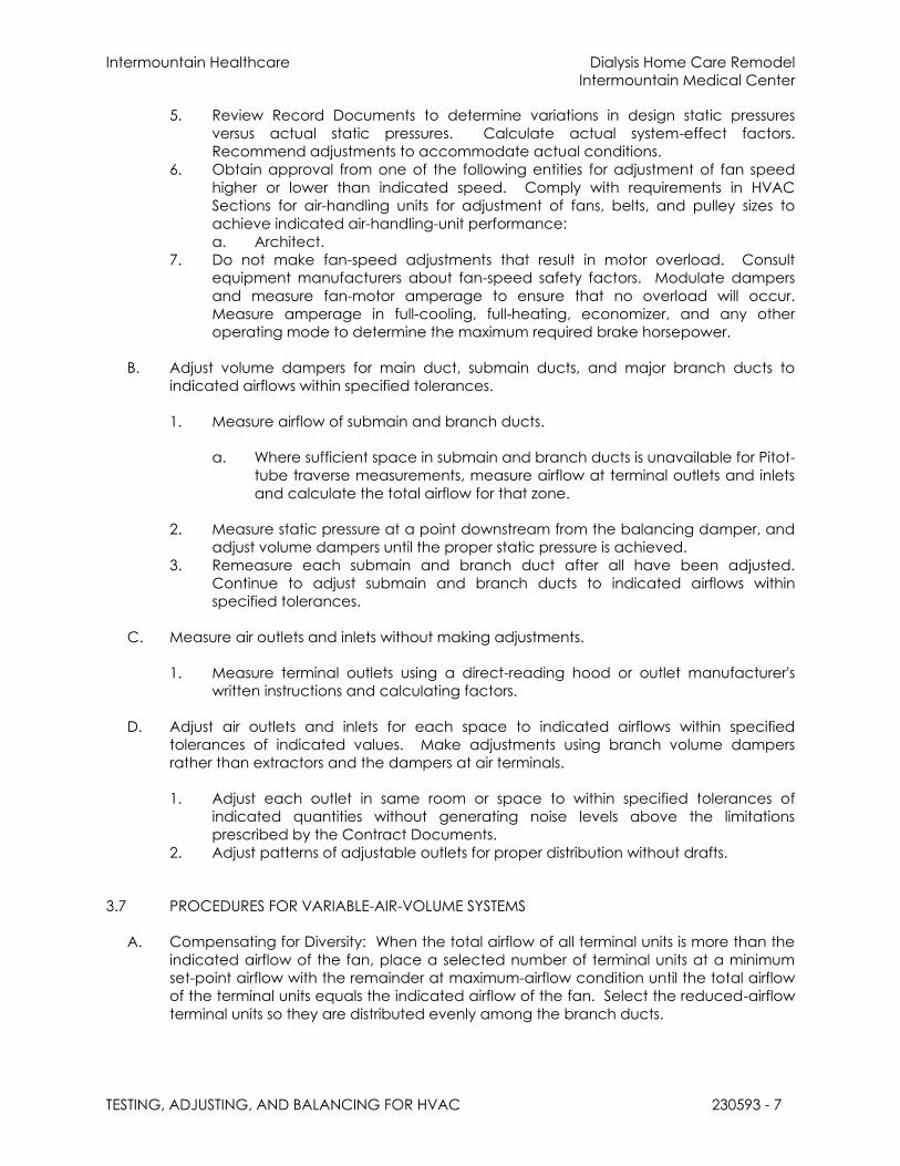
Intermountain Healthcare Dialysis Home Care Remodel
Intermountain Medical Center
TESTING, ADJUSTING, AND BALANCING FOR HVAC 230593 - 7
5. Review Record Documents to determine variations in design static pressures
versus actual static pressures. Calculate actual system-effect factors.
Recommend adjustments to accommodate actual conditions.
6. Obtain approval from one of the following entities for adjustment of fan speed
higher or lower than indicated speed. Comply with requirements in HVAC
Sections for air-handling units for adjustment of fans, belts, and pulley sizes to
achieve indicated air-handling-unit performance:
a. Architect.
7. Do not make fan-speed adjustments that result in motor overload. Consult
equipment manufacturers about fan-speed safety factors. Modulate dampers
and measure fan-motor amperage to ensure that no overload will occur.
Measure amperage in full-cooling, full-heating, economizer, and any other
operating mode to determine the maximum required brake horsepower.
B. Adjust volume dampers for main duct, submain ducts, and major branch ducts to
indicated airflows within specified tolerances.
1. Measure airflow of submain and branch ducts.
a. Where sufficient space in submain and branch ducts is unavailable for Pitot-
tube traverse measurements, measure airflow at terminal outlets and inlets
and calculate the total airflow for that zone.
2. Measure static pressure at a point downstream from the balancing damper, and
adjust volume dampers until the proper static pressure is achieved.
3. Remeasure each submain and branch duct after all have been adjusted.
Continue to adjust submain and branch ducts to indicated airflows within
specified tolerances.
C. Measure air outlets and inlets without making adjustments.
1. Measure terminal outlets using a direct-reading hood or outlet manufacturer's
written instructions and calculating factors.
D. Adjust air outlets and inlets for each space to indicated airflows within specified
tolerances of indicated values. Make adjustments using branch volume dampers
rather than extractors and the dampers at air terminals.
1. Adjust each outlet in same room or space to within specified tolerances of
indicated quantities without generating noise levels above the limitations
prescribed by the Contract Documents.
2. Adjust patterns of adjustable outlets for proper distribution without drafts.
3.7 PROCEDURES FOR VARIABLE-AIR-VOLUME SYSTEMS
A. Compensating for Diversity: When the total airflow of all terminal units is more than the
indicated airflow of the fan, place a selected number of terminal units at a minimum
set-point airflow with the remainder at maximum-airflow condition until the total airflow
of the terminal units equals the indicated airflow of the fan. Select the reduced-airflow
terminal units so they are distributed evenly among the branch ducts.

Intermountain Healthcare Dialysis Home Care Remodel
Intermountain Medical Center
TESTING, ADJUSTING, AND BALANCING FOR HVAC 230593 - 8
B. Pressure-Independent, Variable-Air-Volume Systems: After the fan systems have been
adjusted, adjust the variable-air-volume systems as follows:
1. Set outdoor-air dampers at minimum, and set return- and exhaust-air dampers at
a position that simulates full-cooling load.
2. Select the terminal unit that is most critical to the supply-fan airflow and static
pressure. Measure static pressure. Adjust system static pressure so the entering
static pressure for the critical terminal unit is not less than the sum of the terminal-
unit manufacturer's recommended minimum inlet static pressure plus the static
pressure needed to overcome terminal-unit discharge system losses.
3. Measure total system airflow. Adjust to within indicated airflow.
4. Set terminal units at maximum airflow and adjust controller or regulator to deliver
the designed maximum airflow. Use terminal-unit manufacturer's written
instructions to make this adjustment. When total airflow is correct, balance the air
outlets downstream from terminal units the same as described for constant-
volume air systems.
5. Set terminal units at minimum airflow and adjust controller or regulator to deliver
the designed minimum airflow. Check air outlets for a proportional reduction in
airflow the same as described for constant-volume air systems.
a. If air outlets are out of balance at minimum airflow, report the condition but
leave outlets balanced for maximum airflow.
6. Remeasure the return airflow to the fan while operating at maximum return
airflow and minimum outdoor airflow.
7. Measure static pressure at the most critical terminal unit and adjust the static-
pressure controller at the main supply-air sensing station to ensure that adequate
static pressure is maintained at the most critical unit.
8. Record final fan-performance data.
C. Pressure-Dependent, Variable-Air-Volume Systems without Diversity: After the fan
systems have been adjusted, adjust the variable-air-volume systems as follows:
1. Balance variable-air-volume systems the same as described for constant-volume
air systems.
2. Set terminal units and supply fan at full-airflow condition.
3. Adjust inlet dampers of each terminal unit to indicated airflow and verify
operation of the static-pressure controller. When total airflow is correct, balance
the air outlets downstream from terminal units the same as described for
constant-volume air systems.
4. Readjust fan airflow for final maximum readings.
5. Measure operating static pressure at the sensor that controls the supply fan if one
is installed, and verify operation of the static-pressure controller.
6. Set terminal units at minimum airflow and adjust controller or regulator to deliver
the designed minimum airflow. Check air outlets for a proportional reduction in
airflow the same as described for constant-volume air systems.
a. If air outlets are out of balance at minimum airflow, report the condition but
leave the outlets balanced for maximum airflow.
7. Measure the return airflow to the fan while operating at maximum return airflow
and minimum outdoor airflow.

Intermountain Healthcare Dialysis Home Care Remodel
Intermountain Medical Center
TESTING, ADJUSTING, AND BALANCING FOR HVAC 230593 - 9
D. Pressure-Dependent, Variable-Air-Volume Systems with Diversity: After the fan systems
have been adjusted, adjust the variable-air-volume systems as follows:
1. Set system at maximum indicated airflow by setting the required number of
terminal units at minimum airflow. Select the reduced-airflow terminal units so
they are distributed evenly among the branch ducts.
2. Adjust supply fan to maximum indicated airflow with the variable-airflow
controller set at maximum airflow.
3. Set terminal units at full-airflow condition.
4. Adjust terminal units starting at the supply-fan end of the system and continuing
progressively to the end of the system. Adjust inlet dampers of each terminal unit
to indicated airflow. When total airflow is correct, balance the air outlets
downstream from terminal units the same as described for constant-volume air
systems.
5. Adjust terminal units for minimum airflow.
6. Measure the return airflow to the fan while operating at maximum return airflow
and minimum outdoor airflow. Adjust the fan and balance the return-air ducts
and inlets the same as described for constant-volume air systems.
3.8 GENERAL PROCEDURES FOR HYDRONIC SYSTEMS
A. Prepare test reports with pertinent design data, and number in sequence starting at
pump to end of system. Check the sum of branch-circuit flows against the approved
pump flow rate. Correct variations that exceed plus or minus 5 percent.
B. Prepare schematic diagrams of systems' "as-built" piping layouts.
C. Prepare hydronic systems for testing and balancing according to the following, in
addition to the general preparation procedures specified above:
1. Open all manual valves for maximum flow.
2. Check liquid level in expansion tank.
3. Check makeup water-station pressure gage for adequate pressure for highest
vent.
4. Check flow-control valves for specified sequence of operation, and set at
indicated flow.
5. Set differential-pressure control valves at the specified differential pressure. Do
not set at fully closed position when pump is positive-displacement type unless
several terminal valves are kept open.
6. Set system controls so automatic valves are wide open to heat exchangers.
7. Check pump-motor load. If motor is overloaded, throttle main flow-balancing
device so motor nameplate rating is not exceeded.
8. Check air vents for a forceful liquid flow exiting from vents when manually
operated.
3.9 PROCEDURES FOR CONSTANT-FLOW HYDRONIC SYSTEMS
A. Measure water flow at pumps. Use the following procedures except for positive-
displacement pumps:

Intermountain Healthcare Dialysis Home Care Remodel
Intermountain Medical Center
TESTING, ADJUSTING, AND BALANCING FOR HVAC 230593 - 10
1. Verify impeller size by operating the pump with the discharge valve closed. Read
pressure differential across the pump. Convert pressure to head and correct for
differences in gage heights. Note the point on manufacturer's pump curve at
zero flow and verify that the pump has the intended impeller size.
a. If impeller sizes must be adjusted to achieve pump performance, obtain
approval from the following entity and comply with requirements in
Section 232123 "Hydronic Pumps.”:
1) Architect.
2. Check system resistance. With all valves open, read pressure differential across
the pump and mark pump manufacturer's head-capacity curve. Adjust pump
discharge valve until indicated water flow is achieved.
a. Monitor motor performance during procedures and do not operate motors
in overload conditions.
3. Verify pump-motor brake horsepower. Calculate the intended brake horsepower
for the system based on pump manufacturer's performance data. Compare
calculated brake horsepower with nameplate data on the pump motor. Report
conditions where actual amperage exceeds motor nameplate amperage.
4. Report flow rates that are not within plus or minus 10 percent of design.
B. Measure flow at all automatic flow control valves to verify that valves are functioning as
designed.
C. Measure flow at all pressure-independent characterized control valves, with valves in
fully open position, to verify that valves are functioning as designed.
D. Set calibrated balancing valves, if installed, at calculated presettings.
E. Measure flow at all stations and adjust, where necessary, to obtain first balance.
1. System components that have Cv rating or an accurately cataloged flow-
pressure-drop relationship may be used as a flow-indicating device.
F. Measure flow at main balancing station and set main balancing device to achieve
flow that is 5 percent greater than indicated flow.
G. Adjust balancing stations to within specified tolerances of indicated flow rate as follows:
1. Determine the balancing station with the highest percentage over indicated
flow.
2. Adjust each station in turn, beginning with the station with the highest
percentage over indicated flow and proceeding to the station with the lowest
percentage over indicated flow.
3. Record settings and mark balancing devices.
H. Measure pump flow rate and make final measurements of pump amperage, voltage,
rpm, pump heads, and systems' pressures and temperatures including outdoor-air
temperature.

Intermountain Healthcare Dialysis Home Care Remodel
Intermountain Medical Center
TESTING, ADJUSTING, AND BALANCING FOR HVAC 230593 - 11
I. Measure the differential-pressure-control-valve settings existing at the conclusion of
balancing.
J. Check settings and operation of each safety valve. Record settings.
3.10 PROCEDURES FOR VARIABLE-FLOW HYDRONIC SYSTEMS
A. Balance systems with automatic two- and three-way control valves by setting systems
at maximum flow through heat-exchange terminals and proceed as specified above
for hydronic systems.
3.11 PROCEDURES FOR PRIMARY-SECONDARY HYDRONIC SYSTEMS
A. Balance the primary circuit flow first and then balance the secondary circuits.
3.12 PROCEDURES FOR STEAM SYSTEMS
A. Measure and record upstream and downstream pressure of each piece of equipment.
B. Measure and record upstream and downstream steam pressure of pressure-reducing
valves.
C. Check settings and operation of automatic temperature-control valves, self-contained
control valves, and pressure-reducing valves. Record final settings.
D. Check settings and operation of each safety valve. Record settings.
E. Verify the operation of each steam trap.
3.13 PROCEDURES FOR HEAT EXCHANGERS
A. Measure water flow through all circuits.
B. Adjust water flow to within specified tolerances.
C. Measure inlet and outlet water temperatures.
D. Measure inlet steam pressure.
E. Check settings and operation of safety and relief valves. Record settings.
3.14 PROCEDURES FOR MOTORS
A. Motors, 1/2 HP and Larger: Test at final balanced conditions and record the following
data:
1. Manufacturer's name, model number, and serial number.
2. Motor horsepower rating.

Intermountain Healthcare Dialysis Home Care Remodel
Intermountain Medical Center
TESTING, ADJUSTING, AND BALANCING FOR HVAC 230593 - 12
3. Motor rpm.
4. Efficiency rating.
5. Nameplate and measured voltage, each phase.
6. Nameplate and measured amperage, each phase.
7. Starter thermal-protection-element rating.
B. Motors Driven by Variable-Frequency Controllers: Test for proper operation at speeds
varying from minimum to maximum. Test the manual bypass of the controller to prove
proper operation. Record observations including name of controller manufacturer,
model number, serial number, and nameplate data.
3.15 PROCEDURES FOR CHILLERS
A. Balance water flow through each evaporator and condenser to within specified
tolerances of indicated flow with all pumps operating. With only one chiller operating
in a multiple chiller installation, do not exceed the flow for the maximum tube velocity
recommended by the chiller manufacturer. Measure and record the following data
with each chiller operating at design conditions:
1. Evaporator-water entering and leaving temperatures, pressure drop, and water
flow.
2. For water-cooled chillers, condenser-water entering and leaving temperatures,
pressure drop, and water flow.
3. Evaporator and condenser refrigerant temperatures and pressures, using
instruments furnished by chiller manufacturer.
4. Power factor if factory-installed instrumentation is furnished for measuring
kilowatts.
5. Kilowatt input if factory-installed instrumentation is furnished for measuring
kilowatts.
6. Capacity: Calculate in tons of cooling.
7. For air-cooled chillers, verify condenser-fan rotation and record fan and motor
data including number of fans and entering- and leaving-air temperatures.
3.16 PROCEDURES FOR COOLING TOWERS
A. Shut off makeup water for the duration of the test, and verify that makeup and
blowdown systems are fully operational after tests and before leaving the equipment.
Perform the following tests and record the results:
1. Measure condenser-water flow to each cell of the cooling tower.
2. Measure entering- and leaving-water temperatures.
3. Measure wet- and dry-bulb temperatures of entering air.
4. Measure wet- and dry-bulb temperatures of leaving air.
5. Measure condenser-water flow rate recirculating through the cooling tower.
6. Measure cooling-tower spray pump discharge pressure.
7. Adjust water level and feed rate of makeup water system.
8. Measure flow through bypass.
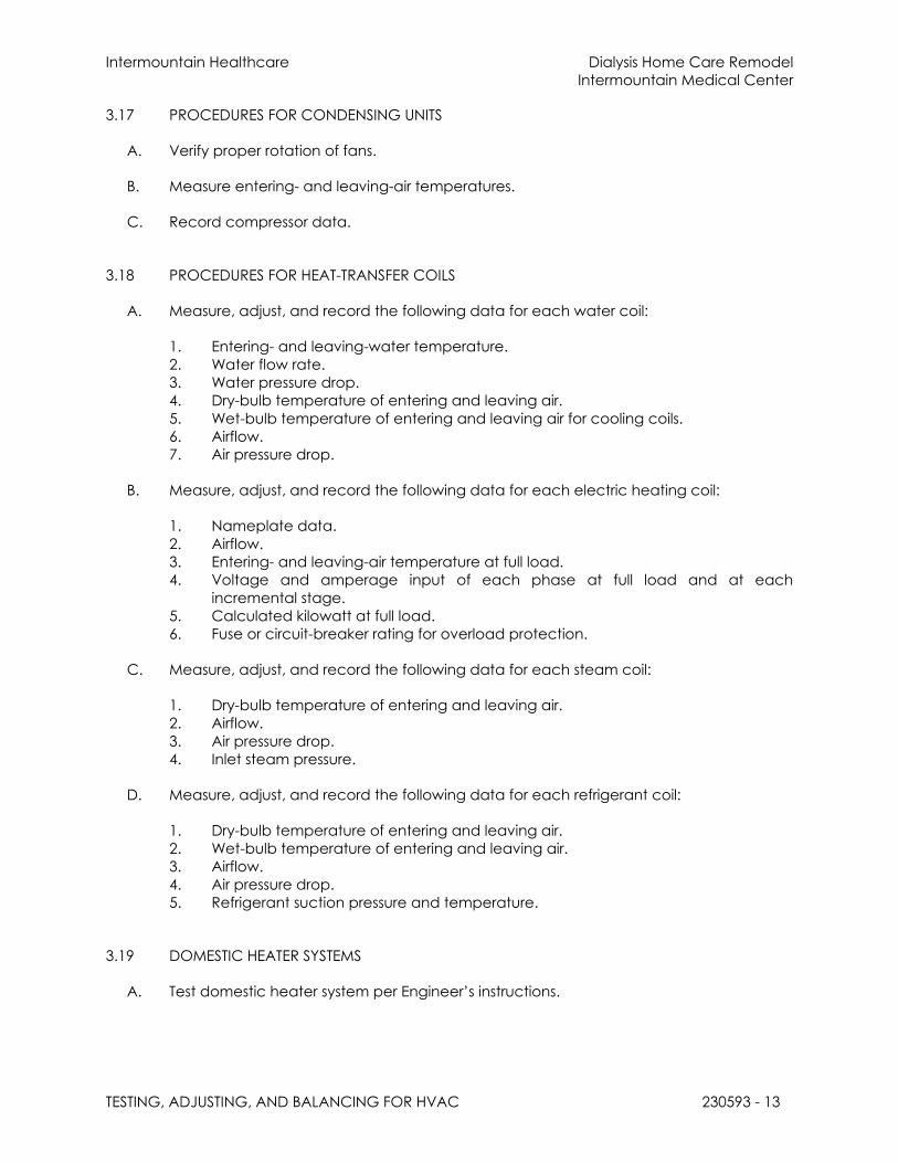
Intermountain Healthcare Dialysis Home Care Remodel
Intermountain Medical Center
TESTING, ADJUSTING, AND BALANCING FOR HVAC 230593 - 13
3.17 PROCEDURES FOR CONDENSING UNITS
A. Verify proper rotation of fans.
B. Measure entering- and leaving-air temperatures.
C. Record compressor data.
3.18 PROCEDURES FOR HEAT-TRANSFER COILS
A. Measure, adjust, and record the following data for each water coil:
1. Entering- and leaving-water temperature.
2. Water flow rate.
3. Water pressure drop.
4. Dry-bulb temperature of entering and leaving air.
5. Wet-bulb temperature of entering and leaving air for cooling coils.
6. Airflow.
7. Air pressure drop.
B. Measure, adjust, and record the following data for each electric heating coil:
1. Nameplate data.
2. Airflow.
3. Entering- and leaving-air temperature at full load.
4. Voltage and amperage input of each phase at full load and at each
incremental stage.
5. Calculated kilowatt at full load.
6. Fuse or circuit-breaker rating for overload protection.
C. Measure, adjust, and record the following data for each steam coil:
1. Dry-bulb temperature of entering and leaving air.
2. Airflow.
3. Air pressure drop.
4. Inlet steam pressure.
D. Measure, adjust, and record the following data for each refrigerant coil:
1. Dry-bulb temperature of entering and leaving air.
2. Wet-bulb temperature of entering and leaving air.
3. Airflow.
4. Air pressure drop.
5. Refrigerant suction pressure and temperature.
3.19 DOMESTIC HEATER SYSTEMS
A. Test domestic heater system per Engineer’s instructions.

Intermountain Healthcare Dialysis Home Care Remodel
Intermountain Medical Center
TESTING, ADJUSTING, AND BALANCING FOR HVAC 230593 - 14
3.20 TOLERANCES
A. Set HVAC system's air flow rates and water flow rates within the following tolerances:
1. Supply, Return, and Exhaust Fans and Equipment with Fans: Plus or minus 10
percent .
2. Air Outlets and Inlets: Plus or minus 10 percent.
3. Heating-Water Flow Rate: Plus or minus 10 percent.
4. Cooling-Water Flow Rate: Plus or minus 10 percent.
3.21 REPORTING
A. Initial Construction-Phase Report: Based on examination of the Contract Documents as
specified in "Examination" Article, prepare a report on the adequacy of design for
systems' balancing devices. Recommend changes and additions to systems'
balancing devices to facilitate proper performance measuring and balancing.
Recommend changes and additions to HVAC systems and general construction to
allow access for performance measuring and balancing devices.
B. Status Reports: Prepare progress reports on the following interval to describe
completed procedures, procedures in progress, and scheduled procedures. Include a
list of deficiencies and problems found in systems being tested and balanced. Prepare
a separate report for each system and each building floor for systems serving multiple
floors;
1. Weekly.
3.22 FINAL REPORT
A. General: Prepare a certified written report; tabulate and divide the report into
separate sections for tested systems and balanced systems.
1. Include a certification sheet at the front of the report's binder, signed and sealed
by the certified testing and balancing engineer.
2. Include a list of instruments used for procedures, along with proof of calibration.
B. Final Report Contents: In addition to certified field-report data, include the following:
1. Pump curves.
2. Fan curves.
3. Manufacturers' test data.
4. Field test reports prepared by system and equipment installers.
5. Other information relative to equipment performance; do not include Shop
Drawings and product data.
C. General Report Data: In addition to form titles and entries, include the following data:
1. Title page.
2. Name and address of the TAB contractor.
3. Project name.
4. Project location.
5. Architect's name and address.

Intermountain Healthcare Dialysis Home Care Remodel
Intermountain Medical Center
TESTING, ADJUSTING, AND BALANCING FOR HVAC 230593 - 15
6. Engineer's name and address.
7. Contractor's name and address.
8. Report date.
9. Signature of TAB supervisor who certifies the report.
10. Table of Contents with the total number of pages defined for each section of the
report. Number each page in the report.
11. Summary of contents including the following:
a. Indicated versus final performance.
b. Notable characteristics of systems.
c. Description of system operation sequence if it varies from the Contract
Documents.
12. Nomenclature sheets for each item of equipment.
13. Data for terminal units, including manufacturer's name, type, size, and fittings.
14. Notes to explain why certain final data in the body of reports vary from indicated
values.
15. Test conditions for fans and pump performance forms including the following:
a. Settings for outdoor-, return-, and exhaust-air dampers.
b. Conditions of filters.
c. Cooling coil, wet- and dry-bulb conditions.
d. Face and bypass damper settings at coils.
e. Fan drive settings including settings and percentage of maximum pitch
diameter.
f. Inlet vane settings for variable-air-volume systems.
g. Settings for supply-air, static-pressure controller.
h. Other system operating conditions that affect performance.
D. System Diagrams: Include schematic layouts of air and hydronic distribution systems.
Present each system with single-line diagram and include the following:
1. Quantities of outdoor, supply, return, and exhaust airflows.
2. Water and steam flow rates.
3. Duct, outlet, and inlet sizes.
4. Pipe and valve sizes and locations.
5. Terminal units.
6. Balancing stations.
7. Position of balancing devices.
E. Air-Handling-Unit Test Reports: For air-handling units with coils, include the following:
1. Unit Data:
a. Unit identification.
b. Location.
c. Make and type.
d. Model number and unit size.
e. Manufacturer's serial number.
f. Unit arrangement and class.
g. Discharge arrangement.
h. Sheave make, size in inches, and bore.

Intermountain Healthcare Dialysis Home Care Remodel
Intermountain Medical Center
TESTING, ADJUSTING, AND BALANCING FOR HVAC 230593 - 16
i. Center-to-center dimensions of sheave, and amount of adjustments in
inches.
j. Number, make, and size of belts.
k. Number, type, and size of filters.
2. Motor Data:
a. Motor make, and frame type and size.
b. Horsepower and rpm.
c. Volts, phase, and hertz.
d. Full-load amperage and service factor.
e. Sheave make, size in inches, and bore.
f. Center-to-center dimensions of sheave, and amount of adjustments in
inches.
3. Test Data (Indicated and Actual Values):
a. Total air flow rate in cfm.
b. Total system static pressure in inches wg.
c. Fan rpm.
d. Discharge static pressure in inches wg.
e. Filter static-pressure differential in inches wg.
f. Preheat-coil static-pressure differential in inches wg.
g. Cooling-coil static-pressure differential in inches wg.
h. Heating-coil static-pressure differential in inches wg.
i. Outdoor airflow in cfm.
j. Return airflow in cfm.
k. Outdoor-air damper position.
l. Return-air damper position.
m. Vortex damper position.
F. Apparatus-Coil Test Reports:
1. Coil Data:
a. System identification.
b. Location.
c. Coil type.
d. Number of rows.
e. Fin spacing in fins per inch o.c.
f. Make and model number.
g. Face area in sq. ft..
h. Tube size in NPS.
i. Tube and fin materials.
j. Circuiting arrangement.
2. Test Data (Indicated and Actual Values):
a. Air flow rate in cfm.
b. Average face velocity in fpm.
c. Air pressure drop in inches wg.
d. Outdoor-air, wet- and dry-bulb temperatures in deg F.
e. Return-air, wet- and dry-bulb temperatures in deg F.

Intermountain Healthcare Dialysis Home Care Remodel
Intermountain Medical Center
TESTING, ADJUSTING, AND BALANCING FOR HVAC 230593 - 17
f. Entering-air, wet- and dry-bulb temperatures in deg F.
g. Leaving-air, wet- and dry-bulb temperatures in deg F.
h. Water flow rate in gpm.
i. Water pressure differential in feet of head or psig.
j. Entering-water temperature in deg F.
k. Leaving-water temperature in deg F.
l. Refrigerant expansion valve and refrigerant types.
m. Refrigerant suction pressure in psig.
n. Refrigerant suction temperature in deg F.
o. Inlet steam pressure in psig.
G. Gas- and Oil-Fired Heat Apparatus Test Reports: In addition to manufacturer's factory
startup equipment reports, include the following:
1. Unit Data:
a. System identification.
b. Location.
c. Make and type.
d. Model number and unit size.
e. Manufacturer's serial number.
f. Fuel type in input data.
g. Output capacity in Btu/h.
h. Ignition type.
i. Burner-control types.
j. Motor horsepower and rpm.
k. Motor volts, phase, and hertz.
l. Motor full-load amperage and service factor.
m. Sheave make, size in inches, and bore.
n. Center-to-center dimensions of sheave, and amount of adjustments in
inches.
2. Test Data (Indicated and Actual Values):
a. Total air flow rate in cfm.
b. Entering-air temperature in deg F.
c. Leaving-air temperature in deg F.
d. Air temperature differential in deg F.
e. Entering-air static pressure in inches wg.
f. Leaving-air static pressure in inches wg.
g. Air static-pressure differential in inches wg.
h. Low-fire fuel input in Btu/h.
i. High-fire fuel input in Btu/h.
j. Manifold pressure in psig.
k. High-temperature-limit setting in deg F.
l. Operating set point in Btu/h.
m. Motor voltage at each connection.
n. Motor amperage for each phase.
o. Heating value of fuel in Btu/h.
H. Fan Test Reports: For supply, return, and exhaust fans, include the following:

Intermountain Healthcare Dialysis Home Care Remodel
Intermountain Medical Center
TESTING, ADJUSTING, AND BALANCING FOR HVAC 230593 - 18
1. Fan Data:
a. System identification.
b. Location.
c. Make and type.
d. Model number and size.
e. Manufacturer's serial number.
f. Arrangement and class.
g. Sheave make, size in inches, and bore.
h. Center-to-center dimensions of sheave, and amount of adjustments in
inches.
2. Motor Data:
a. Motor make, and frame type and size.
b. Horsepower and rpm.
c. Volts, phase, and hertz.
d. Full-load amperage and service factor.
e. Sheave make, size in inches, and bore.
f. Center-to-center dimensions of sheave, and amount of adjustments in
inches.
g. Number, make, and size of belts.
3. Test Data (Indicated and Actual Values):
a. Total airflow rate in cfm.
b. Total system static pressure in inches wg.
c. Fan rpm.
d. Discharge static pressure in inches wg.
e. Suction static pressure in inches wg.
I. Round, Flat-Oval, and Rectangular Duct Traverse Reports: Include a diagram with a
grid representing the duct cross-section and record the following:
1. Report Data:
a. System and air-handling-unit number.
b. Location and zone.
c. Traverse air temperature in deg F.
d. Duct static pressure in inches wg.
e. Duct size in inches.
f. Duct area in sq. ft..
g. Indicated air flow rate in cfm.
h. Indicated velocity in fpm.
i. Actual air flow rate in cfm.
j. Actual average velocity in fpm.
k. Barometric pressure in psig.
J. Air-Terminal-Device Reports:
1. Unit Data:
a. System and air-handling unit identification.

Intermountain Healthcare Dialysis Home Care Remodel
Intermountain Medical Center
TESTING, ADJUSTING, AND BALANCING FOR HVAC 230593 - 19
b. Location and zone.
c. Apparatus used for test.
d. Area served.
e. Make.
f. Number from system diagram.
g. Type and model number.
h. Size.
i. Effective area in sq. ft..
2. Test Data (Indicated and Actual Values):
a. Air flow rate in cfm.
b. Air velocity in fpm.
c. Preliminary air flow rate as needed in cfm.
d. Preliminary velocity as needed in fpm.
e. Final air flow rate in cfm.
f. Final velocity in fpm.
g. Space temperature in deg F.
K. System-Coil Reports: For reheat coils and water coils of terminal units, include the
following:
1. Unit Data:
a. System and air-handling-unit identification.
b. Location and zone.
c. Room or riser served.
d. Coil make and size.
e. Flowmeter type.
2. Test Data (Indicated and Actual Values):
a. Air flow rate in cfm.
b. Entering-water temperature in deg F.
c. Leaving-water temperature in deg F.
d. Water pressure drop in feet of head or psig.
e. Entering-air temperature in deg F.
f. Leaving-air temperature in deg F.
L. Pump Test Reports: Calculate impeller size by plotting the shutoff head on pump curves
and include the following:
1. Unit Data:
a. Unit identification.
b. Location.
c. Service.
d. Make and size.
e. Model number and serial number.
f. Water flow rate in gpm.
g. Water pressure differential in feet of head or psig.
h. Required net positive suction head in feet of head or psig.
i. Pump rpm.

Intermountain Healthcare Dialysis Home Care Remodel
Intermountain Medical Center
TESTING, ADJUSTING, AND BALANCING FOR HVAC 230593 - 20
j. Impeller diameter in inches.
k. Motor make and frame size.
l. Motor horsepower and rpm.
m. Voltage at each connection.
n. Amperage for each phase.
o. Full-load amperage and service factor.
p. Seal type.
2. Test Data (Indicated and Actual Values):
a. Static head in feet of head or psig.
b. Pump shutoff pressure in feet of head or psig.
c. Actual impeller size in inches.
d. Full-open flow rate in gpm.
e. Full-open pressure in feet of head or psig.
f. Final discharge pressure in feet of head or psig.
g. Final suction pressure in feet of head or psig.
h. Final total pressure in feet of head or psig.
i. Final water flow rate in gpm.
j. Voltage at each connection.
k. Amperage for each phase.
M. Instrument Calibration Reports:
1. Report Data:
a. Instrument type and make.
b. Serial number.
c. Application.
d. Dates of use.
e. Dates of calibration.
3.23 INSPECTIONS
A. Initial Inspection:
1. After testing and balancing are complete, operate each system and randomly
check measurements to verify that the system is operating according to the final
test and balance readings documented in the final report.
2. Check the following for each system:
a. Measure airflow of at least 10 percent of air outlets.
b. Measure water flow of at least 5 percent of terminals.
c. Measure room temperature at each thermostat/temperature sensor.
Compare the reading to the set point.
d. Verify that balancing devices are marked with final balance position.
e. Note deviations from the Contract Documents in the final report.
B. Final Inspection:

Intermountain Healthcare Dialysis Home Care Remodel
Intermountain Medical Center
TESTING, ADJUSTING, AND BALANCING FOR HVAC 230593 - 21
1. After initial inspection is complete and documentation by random checks verifies
that testing and balancing are complete and accurately documented in the
final report, request that a final inspection be made by:
a. Architect.
2. The TAB contractor's test and balance engineer shall conduct the inspection in
the presence of:
a. Architect.
3. The following entity shall randomly select measurements, documented in the final
report, to be rechecked. Rechecking shall be limited to either 10 percent of the
total measurements recorded or the extent of measurements that can be
accomplished in a normal 8-hour business day:
a. Architect.
4. If rechecks yield measurements that differ from the measurements documented
in the final report by more than the tolerances allowed, the measurements shall
be noted as "FAILED."
5. If the number of "FAILED" measurements is greater than 10 percent of the total
measurements checked during the final inspection, the testing and balancing
shall be considered incomplete and shall be rejected.
C. TAB Work will be considered defective if it does not pass final inspections. If TAB Work
fails, proceed as follows:
1. Recheck all measurements and make adjustments. Revise the final report and
balancing device settings to include all changes; resubmit the final report and
request a second final inspection.
2. If the second final inspection also fails, Owner may contract the services of
another TAB contractor to complete TAB Work according to the Contract
Documents and deduct the cost of the services from the original TAB contractor's
final payment.
D. Prepare test and inspection reports.
3.24 ADDITIONAL TESTS
A. Within 90 days of completing TAB, perform additional TAB to verify that balanced
conditions are being maintained throughout and to correct unusual conditions.
B. Seasonal Periods: If initial TAB procedures were not performed during near-peak
summer and winter conditions, perform additional TAB during near-peak summer and
winter conditions.
END OF SECTION 230593
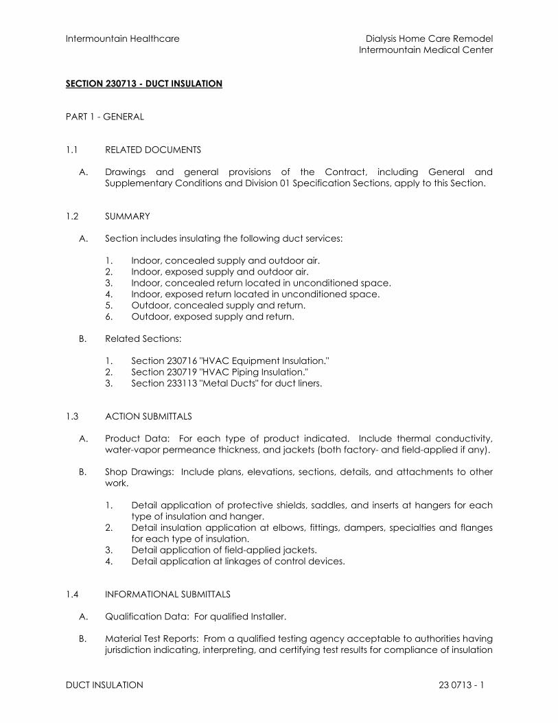
Intermountain Healthcare Dialysis Home Care Remodel
Intermountain Medical Center
DUCT INSULATION 23 0713 - 1
SECTION 230713 - DUCT INSULATION
PART 1 - GENERAL
1.1 RELATED DOCUMENTS
A. Drawings and general provisions of the Contract, including General and
Supplementary Conditions and Division 01 Specification Sections, apply to this Section.
1.2 SUMMARY
A. Section includes insulating the following duct services:
1. Indoor, concealed supply and outdoor air.
2. Indoor, exposed supply and outdoor air.
3. Indoor, concealed return located in unconditioned space.
4. Indoor, exposed return located in unconditioned space.
5. Outdoor, concealed supply and return.
6. Outdoor, exposed supply and return.
B. Related Sections:
1. Section 230716 "HVAC Equipment Insulation."
2. Section 230719 "HVAC Piping Insulation."
3. Section 233113 "Metal Ducts" for duct liners.
1.3 ACTION SUBMITTALS
A. Product Data: For each type of product indicated. Include thermal conductivity,
water-vapor permeance thickness, and jackets (both factory- and field-applied if any).
B. Shop Drawings: Include plans, elevations, sections, details, and attachments to other
work.
1. Detail application of protective shields, saddles, and inserts at hangers for each
type of insulation and hanger.
2. Detail insulation application at elbows, fittings, dampers, specialties and flanges
for each type of insulation.
3. Detail application of field-applied jackets.
4. Detail application at linkages of control devices.
1.4 INFORMATIONAL SUBMITTALS
A. Qualification Data: For qualified Installer.
B. Material Test Reports: From a qualified testing agency acceptable to authorities having
jurisdiction indicating, interpreting, and certifying test results for compliance of insulation

Intermountain Healthcare Dialysis Home Care Remodel
Intermountain Medical Center
DUCT INSULATION 23 0713 - 2
materials, sealers, attachments, cements, and jackets, with requirements indicated.
Include dates of tests and test methods employed.
C. Field quality-control reports.
1.5 QUALITY ASSURANCE
A. Installer Qualifications: Skilled mechanics who have successfully completed an
apprenticeship program or another craft training program certified by the Department
of Labor, Bureau of Apprenticeship and Training.
B. Surface-Burning Characteristics: For insulation and related materials, as determined by
testing identical products according to ASTM E 84, by a testing agency acceptable to
authorities having jurisdiction. Factory label insulation and jacket materials and
adhesive, mastic, tapes, and cement material containers, with appropriate markings of
applicable testing agency.
1. Insulation Installed Indoors: Flame-spread index of 25 or less, and smoke-
developed index of 50 or less.
2. Insulation Installed Outdoors: Flame-spread index of 75 or less, and smoke-
developed index of 150 or less.
1.6 DELIVERY, STORAGE, AND HANDLING
A. Packaging: Insulation material containers shall be marked by manufacturer with
appropriate ASTM standard designation, type and grade, and maximum use
temperature.
1.7 COORDINATION
A. Coordinate sizes and locations of supports, hangers, and insulation shields specified in
Section 230529 "Hangers and Supports for HVAC Piping and Equipment."
B. Coordinate clearance requirements with duct Installer for duct insulation application.
Before preparing ductwork Shop Drawings, establish and maintain clearance
requirements for installation of insulation and field-applied jackets and finishes and for
space required for maintenance.
C. Coordinate installation and testing of heat tracing.
1.8 SCHEDULING
A. Schedule insulation application after pressure testing systems and, where required, after
installing and testing heat tracing. Insulation application may begin on segments that
have satisfactory test results.
B. Complete installation and concealment of plastic materials as rapidly as possible in
each area of construction.
Intermountain Healthcare Dialysis Home Care Remodel
Intermountain Medical Center
DUCT INSULATION 23 0713 - 3
PART 2 - PRODUCTS
2.1 INSULATION MATERIALS
A. Comply with requirements in "Duct Insulation Schedule, General," "Indoor Duct and
Plenum Insulation Schedule," and "Aboveground, Outdoor Duct and Plenum Insulation
Schedule" articles for where insulating materials shall be applied.
B. Products shall not contain asbestos, lead, mercury, or mercury compounds.
C. Products that come in contact with stainless steel shall have a leachable chloride
content of less than 50 ppm when tested according to ASTM C 871.
D. Insulation materials for use on austenitic stainless steel shall be qualified as acceptable
according to ASTM C 795.
E. Foam insulation materials shall not use CFC or HCFC blowing agents in the
manufacturing process.
F. Flexible Elastomeric Insulation: Closed-cell, sponge- or expanded-rubber materials.
Comply with ASTM C 534, Type II for sheet materials.
1. Products: Subject to compliance with requirements, provide one of the following:
a. Aeroflex USA, Inc.; Aerocel.
b. Armacell LLC; AP Armaflex.
c. K-Flex USA; Insul-Sheet, K-Flex Gray Duct Liner, and K-FLEX LS.
G. Mineral-Fiber Blanket Insulation: Mineral or glass fibers bonded with a thermosetting
resin. Comply with ASTM C 553, Type II and ASTM C 1290, Type III with factory-applied
FSK jacket. Factory-applied jacket requirements are specified in "Factory-Applied
Jackets" Article.
1. Products: Subject to compliance with requirements, provide one of the following:
a. CertainTeed Corp.; SoftTouch Duct Wrap.
b. Johns Manville; Microlite.
c. Knauf Insulation; Friendly Feel Duct Wrap.
d. Manson Insulation Inc.; Alley Wrap.
e. Owens Corning; SOFTR All-Service Duct Wrap.
H. Mineral-Fiber Board Insulation: Mineral or glass fibers bonded with a thermosetting resin.
Comply with ASTM C 612, Type IA or Type IB. For duct and plenum applications,
provide insulation with factory-applied ASJ. Factory-applied jacket requirements are
specified in "Factory-Applied Jackets" Article.
1. Products: Subject to compliance with requirements, provide one of the
following:
a. CertainTeed Corp.; Commercial Board.
b. Fibrex Insulations Inc.; FBX.
c. Johns Manville; 800 Series Spin-Glas.

Intermountain Healthcare Dialysis Home Care Remodel
Intermountain Medical Center
DUCT INSULATION 23 0713 - 4
d. Knauf Insulation; Insulation Board.
e. Manson Insulation Inc.; AK Board.
f. Owens Corning; Fiberglas 700 Series.
I. Polyolefin: Unicellular, polyethylene thermal plastic insulation. Comply with ASTM C 534
or ASTM C 1427, Type I, Grade 1 for tubular materials and Type II, Grade 1 for sheet
materials.
1. Products: Subject to compliance with requirements, provide one of the
following:
a. Armacell LLC; Tubolit.
b. Nomaco Insulation; IMCOLOCK, IMCOSHEET, NOMALOCK, and NOMAPLY.
2.2 FIRE-RATED INSULATION SYSTEMS
A. Fire-Rated Board: Structural-grade, press-molded, xonolite calcium silicate, fireproofing
board suitable for operating temperatures up to 1700 deg F. Comply with ASTM C 656,
Type II, Grade 6. Tested and certified to provide a:
a. 2-hour fire rating by an NRTL acceptable to authorities having jurisdiction
1. Products: Subject to compliance with requirements, provide the following :
a. Johns Manville; Super Firetemp M.
B. Fire-Rated Blanket: High-temperature, flexible, blanket insulation with FSK jacket that is
tested and certified to provide a:
a. 2-hour fire rating by an NRTL acceptable to authorities
1. Products: Subject to compliance with requirements, provide one of the following :
a. CertainTeed Corp.; FlameChek.
b. Johns Manville; Firetemp Wrap.
c. Nelson Fire Stop Products; Nelson FSB Flameshield Blanket.
d. Thermal Ceramics; FireMaster Duct Wrap.
e. 3M; Fire Barrier Wrap Products.
f. Unifrax Corporation; FyreWrap.
2.3 ADHESIVES
A. Materials shall be compatible with insulation materials, jackets, and substrates and for
bonding insulation to itself and to surfaces to be insulated unless otherwise indicated.
B. Flexible Elastomeric and Polyolefin Adhesive: Comply with MIL-A-24179A, Type II, Class I.
1. Products: Subject to compliance with requirements, provide one of the following:
a. Aeroflex USA, Inc.; Aeroseal.
b. Armacell LLC; Armaflex 520 Adhesive.

Intermountain Healthcare Dialysis Home Care Remodel
Intermountain Medical Center
DUCT INSULATION 23 0713 - 5
c. Foster Brand, Specialty Construction Brands, Inc., a business of H. B. Fuller
Company; 85-75.
d. K-Flex USA; R-373 Contact Adhesive.
2. For indoor applications, adhesive shall have a VOC content of 50 g/L or less when
calculated according to 40 CFR 59, Subpart D (EPA Method 24).
C. Mineral-Fiber Adhesive: Comply with MIL-A-3316C, Class 2, Grade A.
1. Products: Subject to compliance with requirements, provide one of the following:
a. Childers Brand, Specialty Construction Brands, Inc., a business of H. B. Fuller
Company; CP-127.
b. Eagle Bridges - Marathon Industries; 225.
c. Foster Brand, Specialty Construction Brands, Inc., a business of H. B. Fuller
Company; 85-60/85-70.
d. Mon-Eco Industries, Inc.; 22-25.
2. For indoor applications, adhesive shall have a VOC content of 80 g/L or less when
calculated according to 40 CFR 59, Subpart D (EPA Method 24).
D. FSK Jacket Adhesive, and ASJ Adhesive: Comply with MIL-A-3316C, Class 2, Grade A
for bonding insulation jacket lap seams and joints.
1. Products: Subject to compliance with requirements, provide one of the following:
a. Childers Brand, Specialty Construction Brands, Inc., a business of H. B. Fuller
Company; CP-82.
b. Eagle Bridges - Marathon Industries; 225.
c. Foster Brand, Specialty Construction Brands, Inc., a business of H. B. Fuller
Company; 85-50.
d. Mon-Eco Industries, Inc.; 22-25.
2. For indoor applications, adhesive shall have a VOC content of 50 g/L or less when
calculated according to 40 CFR 59, Subpart D (EPA Method 24).
2.4 MASTICS
A. Materials shall be compatible with insulation materials, jackets, and substrates; comply
with MIL-PRF-19565C, Type II.
1. For indoor applications, use mastics that have a VOC content of 50 g/L or less
when calculated according to 40 CFR 59, Subpart D (EPA Method 24).
B. Vapor-Barrier Mastic: Water based; suitable for indoor use on below ambient services.
1. Products: Subject to compliance with requirements, provide one of the following:
a. Foster Brand, Specialty Construction Brands, Inc., a business of H. B. Fuller
Company; 30-80/30-90.
b. Vimasco Corporation; 749.
Intermountain Healthcare Dialysis Home Care Remodel
Intermountain Medical Center
DUCT INSULATION 23 0713 - 6
2. Water-Vapor Permeance: ASTM E 96/E 96M, Procedure B, 0.013 perm at 43-mil
dry film thickness.
3. Service Temperature Range: Minus 20 to plus 180 deg F.
4. Solids Content: ASTM D 1644, 58 percent by volume and 70 percent by weight.
5. Color: White.
C. Breather Mastic: Water based; suitable for indoor and outdoor use on above ambient
services.
1. Products: Subject to compliance with requirements, provide one of the following:
a. Childers Brand, Specialty Construction Brands, Inc., a business of H. B. Fuller
Company; CP-10.
b. Eagle Bridges - Marathon Industries; 550.
c. Foster Brand, Specialty Construction Brands, Inc., a business of H. B. Fuller
Company; 46-50.
d. Mon-Eco Industries, Inc.; 55-50.
e. Vimasco Corporation; WC-1/WC-5.
2. Water-Vapor Permeance: ASTM F 1249, 1.8 perms at 0.0625-inch dry film
thickness.
3. Service Temperature Range: Minus 20 to plus 180 deg F.
4. Solids Content: 60 percent by volume and 66 percent by weight.
5. Color: White.
2.5 LAGGING ADHESIVES
A. Description: Comply with MIL-A-3316C, Class I, Grade A and shall be compatible with
insulation materials, jackets, and substrates.
1. For indoor applications, use lagging adhesives that have a VOC content of 50 g/L
or less when calculated according to 40 CFR 59, Subpart D (EPA Method 24).
2. Products: Subject to compliance with requirements, provide one of the following:
a. Childers Brand, Specialty Construction Brands, Inc., a business of H. B. Fuller
Company; CP-50 AHV2.
b. Foster Brand, Specialty Construction Brands, Inc., a business of H. B. Fuller
Company; 30-36.
c. Vimasco Corporation; 713 and 714.
3. Fire-resistant, water-based lagging adhesive and coating for use indoors to
adhere fire-resistant lagging cloths over duct insulation.
4. Service Temperature Range: 0 to plus 180 deg F.
5. Color: White.
2.6 SEALANTS
A. FSK and Metal Jacket Flashing Sealants:
1. Products: Subject to compliance with requirements, provide one of the following:

Intermountain Healthcare Dialysis Home Care Remodel
Intermountain Medical Center
DUCT INSULATION 23 0713 - 7
a. Childers Brand, Specialty Construction Brands, Inc., a business of H. B. Fuller
Company; CP-76.
b. Eagle Bridges - Marathon Industries; 405.
c. Foster Brand, Specialty Construction Brands, Inc., a business of H. B. Fuller
Company; 95-44.
d. Mon-Eco Industries, Inc.; 44-05.
2. Materials shall be compatible with insulation materials, jackets, and substrates.
3. Fire- and water-resistant, flexible, elastomeric sealant.
4. Service Temperature Range: Minus 40 to plus 250 deg F.
5. Color: Aluminum.
6. For indoor applications, sealants shall have a VOC content of 420 g/L or less when
calculated according to 40 CFR 59, Subpart D (EPA Method 24).
2.7 FACTORY-APPLIED JACKETS
A. Insulation system schedules indicate factory-applied jackets on various applications.
When factory-applied jackets are indicated, comply with the following:
1. FSK Jacket: Aluminum-foil, fiberglass-reinforced scrim with kraft-paper backing;
complying with ASTM C 1136, Type II.
2.8 FIELD-APPLIED JACKETS
A. Field-applied jackets shall comply with ASTM C 921, Type I, unless otherwise indicated.
B. FSK Jacket: Aluminum-foil-face, fiberglass-reinforced scrim with kraft-paper backing.
C. Metal Jacket:
1. Products: Subject to compliance with requirements, provide one of the following:
a. Childers Brand, Specialty Construction Brands, Inc., a business of H. B. Fuller
Company; Metal Jacketing Systems.
b. ITW Insulation Systems; Aluminum and Stainless Steel Jacketing.
c. RPR Products, Inc.; Insul-Mate.
2. Aluminum Jacket: Comply with ASTM B 209, Alloy 3003, 3005, 3105, or 5005,
Temper H-14.
a. Sheet and roll stock ready for shop or field sizing
b. Finish and thickness are indicated in field-applied jacket schedules.
c. Moisture Barrier for Indoor Applications: 3-mil-thick, heat-bonded
polyethylene and kraft paper.
d. Moisture Barrier for Outdoor Applications: 3-mil-thick, heat-bonded
polyethylene and kraft.

Intermountain Healthcare Dialysis Home Care Remodel
Intermountain Medical Center
DUCT INSULATION 23 0713 - 8
2.9 TAPES
A. FSK Tape: Foil-face, vapor-retarder tape matching factory-applied jacket with acrylic
adhesive; complying with ASTM C 1136.
1. Products: Subject to compliance with requirements, provide one of the following:
a. ABI, Ideal Tape Division; 491 AWF FSK.
b. Avery Dennison Corporation, Specialty Tapes Division; Fasson 0827.
c. Compac Corporation; 110 and 111.
d. Venture Tape; 1525 CW NT, 1528 CW, and 1528 CW/SQ.
2. Width: 3 inches.
3. Thickness: 6.5 mils.
4. Adhesion: 90 ounces force/inch in width.
5. Elongation: 2 percent.
6. Tensile Strength: 40 lbf/inch in width.
7. FSK Tape Disks and Squares: Precut disks or squares of FSK tape.
B. Aluminum-Foil Tape: Vapor-retarder tape with acrylic adhesive.
1. Products: Subject to compliance with requirements, provide one of the following:
a. ABI, Ideal Tape Division; 488 AWF.
b. Avery Dennison Corporation, Specialty Tapes Division; Fasson 0800.
c. Compac Corporation; 120.
d. Venture Tape; 3520 CW.
2. Width: 2 inches.
3. Thickness: 3.7 mils.
4. Adhesion: 100 ounces force/inch in width.
5. Elongation: 5 percent.
6. Tensile Strength: 34 lbf/inch in width.
2.10 SECUREMENTS
A. Bands:
1. Products: Subject to compliance with requirements, provide one of the following:
a. ITW Insulation Systems; Gerrard Strapping and Seals.
b. RPR Products, Inc.; Insul-Mate Strapping, Seals, and Springs.
2. Aluminum: ASTM B 209, Alloy 3003, 3005, 3105, or 5005; Temper H-14, 0.020 inch
thick, 3/4 inch wide with wing seal.
3. Springs: Twin spring set constructed of stainless steel with ends flat and slotted to
accept metal bands. Spring size determined by manufacturer for application.
B. Insulation Pins and Hangers:
1. Capacitor-Discharge-Weld Pins: Copper- or zinc-coated steel pin, fully annealed
for capacitor-discharge welding, 0.135-inch-diameter shank, length to suit depth
of insulation indicated.

Intermountain Healthcare Dialysis Home Care Remodel
Intermountain Medical Center
DUCT INSULATION 23 0713 - 9
a. Products: Subject to compliance with requirements, provide one of the
following:
1) AGM Industries, Inc.; CWP-1.
2) GEMCO; CD.
3) Midwest Fasteners, Inc.; CD.
4) Nelson Stud Welding; TPA, TPC, and TPS.
2. Cupped-Head, Capacitor-Discharge-Weld Pins: Copper- or zinc-coated steel
pin, fully annealed for capacitor-discharge welding, 0.135-inch- diameter shank,
length to suit depth of insulation indicated with integral 1-1/2-inch galvanized
carbon-steel washer.
a. Products: Subject to compliance with requirements, provide one of the
following:
1) AGM Industries, Inc.; CHP-1.
2) GEMCO; Cupped Head Weld Pin.
3) Midwest Fasteners, Inc.; Cupped Head.
4) Nelson Stud Welding; CHP.
3. Metal, Adhesively Attached, Perforated-Base Insulation Hangers: Baseplate
welded to projecting spindle that is capable of holding insulation, of thickness
indicated, securely in position indicated when self-locking washer is in place.
Comply with the following requirements:
a. Products: Subject to compliance with requirements, provide one of the
following:
1) AGM Industries, Inc.; Tactoo Perforated Base Insul-Hangers.
2) GEMCO; Perforated Base.
3) Midwest Fasteners, Inc.; Spindle.
b. Baseplate: Perforated, galvanized carbon-steel sheet, 0.030 inch thick by 2
inches square.
c. Spindle: Copper- or zinc-coated, low-carbon steel fully annealed, 0.106-
inch- diameter shank, length to suit depth of insulation indicated.
d. Adhesive: Recommended by hanger manufacturer. Product with
demonstrated capability to bond insulation hanger securely to substrates
indicated without damaging insulation, hangers, and substrates.
4. Nonmetal, Adhesively Attached, Perforated-Base Insulation Hangers: Baseplate
fastened to projecting spindle that is capable of holding insulation, of thickness
indicated, securely in position indicated when self-locking washer is in place.
Comply with the following requirements:
a. Products: Subject to compliance with requirements, provide one of the
following:
1) GEMCO; Nylon Hangers.
2) Midwest Fasteners, Inc.; Nylon Insulation Hangers.

Intermountain Healthcare Dialysis Home Care Remodel
Intermountain Medical Center
DUCT INSULATION 23 0713 - 10
b. Baseplate: Perforated, nylon sheet, 0.030 inch thick by 1-1/2 inches in
diameter.
c. Spindle: Nylon, 0.106-inch- diameter shank, length to suit depth of insulation
indicated, up to 2-1/2 inches.
d. Adhesive: Recommended by hanger manufacturer. Product with
demonstrated capability to bond insulation hanger securely to substrates
indicated without damaging insulation, hangers, and substrates.
5. Self-Sticking-Base Insulation Hangers: Baseplate welded to projecting spindle that
is capable of holding insulation, of thickness indicated, securely in position
indicated when self-locking washer is in place. Comply with the following
requirements:
a. Products: Subject to compliance with requirements, provide one of the
following:
1) AGM Industries, Inc.; Tactoo Self-Adhering Insul-Hangers.
2) GEMCO; Peel & Press.
3) Midwest Fasteners, Inc.; Self Stick.
b. Baseplate: Galvanized carbon-steel sheet, 0.030 inch thick by 2 inches
square.
c. Spindle: Copper- or zinc-coated, low-carbon steel, fully annealed, 0.106-
inch- diameter shank, length to suit depth of insulation indicated.
d. Adhesive-backed base with a peel-off protective cover.
PART 3 - EXECUTION
3.1 EXAMINATION
A. Examine substrates and conditions for compliance with requirements for installation
tolerances and other conditions affecting performance of insulation application.
1. Verify that systems to be insulated have been tested and are free of defects.
2. Verify that surfaces to be insulated are clean and dry.
B. Proceed with installation only after unsatisfactory conditions have been corrected.
3.2 PREPARATION
A. Surface Preparation: Clean and dry surfaces to receive insulation. Remove materials
that will adversely affect insulation application.
3.3 GENERAL INSTALLATION REQUIREMENTS
A. Install insulation materials, accessories, and finishes with smooth, straight, and even
surfaces; free of voids throughout the length of ducts and fittings.

Intermountain Healthcare Dialysis Home Care Remodel
Intermountain Medical Center
DUCT INSULATION 23 0713 - 11
B. Install insulation materials, vapor barriers or retarders, jackets, and thicknesses required
for each item of duct system as specified in insulation system schedules.
C. Install accessories compatible with insulation materials and suitable for the service.
Install accessories that do not corrode, soften, or otherwise attack insulation or jacket in
either wet or dry state.
D. Install insulation with longitudinal seams at top and bottom of horizontal runs.
E. Install multiple layers of insulation with longitudinal and end seams staggered.
F. Keep insulation materials dry during application and finishing.
G. Install insulation with tight longitudinal seams and end joints. Bond seams and joints with
adhesive recommended by insulation material manufacturer.
H. Install insulation with least number of joints practical.
I. Where vapor barrier is indicated, seal joints, seams, and penetrations in insulation at
hangers, supports, anchors, and other projections with vapor-barrier mastic.
1. Install insulation continuously through hangers and around anchor attachments.
2. For insulation application where vapor barriers are indicated, extend insulation on
anchor legs from point of attachment to supported item to point of attachment
to structure. Taper and seal ends at attachment to structure with vapor-barrier
mastic.
3. Install insert materials and install insulation to tightly join the insert. Seal insulation
to insulation inserts with adhesive or sealing compound recommended by
insulation material manufacturer.
J. Apply adhesives, mastics, and sealants at manufacturer's recommended coverage
rate and wet and dry film thicknesses.
K. Install insulation with factory-applied jackets as follows:
1. Draw jacket tight and smooth.
2. Cover circumferential joints with 3-inch- wide strips, of same material as insulation
jacket. Secure strips with adhesive and outward clinching staples along both
edges of strip, spaced 4 inches o.c.
3. Overlap jacket longitudinal seams at least 1-1/2 inches. Clean and dry surface to
receive self-sealing lap. Staple laps with outward clinching staples along edge
at:
a. 2 inche o.c.
b. For below ambient services, apply vapor-barrier mastic over staples.
4. Cover joints and seams with tape, according to insulation material
manufacturer's written instructions, to maintain vapor seal.
5. Where vapor barriers are indicated, apply vapor-barrier mastic on seams and
joints and at ends adjacent to duct flanges and fittings.
L. Cut insulation in a manner to avoid compressing insulation more than 75 percent of its
nominal thickness.

Intermountain Healthcare Dialysis Home Care Remodel
Intermountain Medical Center
DUCT INSULATION 23 0713 - 12
M. Finish installation with systems at operating conditions. Repair joint separations and
cracking due to thermal movement.
N. Repair damaged insulation facings by applying same facing material over damaged
areas. Extend patches at least 4 inches beyond damaged areas. Adhere, staple, and
seal patches similar to butt joints.
3.4 PENETRATIONS
A. Insulation Installation at Roof Penetrations: Install insulation continuously through roof
penetrations.
1. Seal penetrations with flashing sealant.
2. For applications requiring only indoor insulation, terminate insulation above roof
surface and seal with joint sealant. For applications requiring indoor and outdoor
insulation, install insulation for outdoor applications tightly joined to indoor
insulation ends. Seal joint with joint sealant.
3. Extend jacket of outdoor insulation outside roof flashing at least 2 inches below
top of roof flashing.
4. Seal jacket to roof flashing with flashing sealant.
B. Insulation Installation at Aboveground Exterior Wall Penetrations: Install insulation
continuously through wall penetrations.
1. Seal penetrations with flashing sealant.
2. For applications requiring only indoor insulation, terminate insulation inside wall
surface and seal with joint sealant. For applications requiring indoor and outdoor
insulation, install insulation for outdoor applications tightly joined to indoor
insulation ends. Seal joint with joint sealant.
3. Extend jacket of outdoor insulation outside wall flashing and overlap wall flashing
at least 2 inches.
4. Seal jacket to wall flashing with flashing sealant.
C. Insulation Installation at Interior Wall and Partition Penetrations (That Are Not Fire Rated):
Install insulation continuously through walls and partitions.
D. Insulation Installation at Fire-Rated Wall and Partition Penetrations: Terminate insulation
at fire damper sleeves for fire-rated wall and partition penetrations. Externally insulate
damper sleeves to match adjacent insulation and overlap duct insulation at least 2
inches.
1. Comply with requirements in Section 078413 "Penetration Firestopping"
firestopping and fire-resistive joint sealers.
E. Insulation Installation at Floor Penetrations:
1. Duct: For penetrations through fire-rated assemblies, terminate insulation at fire
damper sleeves and externally insulate damper sleeve beyond floor to match
adjacent duct insulation. Overlap damper sleeve and duct insulation at least 2
inches.
2. Seal penetrations through fire-rated assemblies. Comply with requirements in
Section 078413 "Penetration Firestopping."

Intermountain Healthcare Dialysis Home Care Remodel
Intermountain Medical Center
DUCT INSULATION 23 0713 - 13
3.5 INSTALLATION OF FLEXIBLE ELASTOMERIC INSULATION
A. Seal longitudinal seams and end joints with manufacturer's recommended adhesive to
eliminate openings in insulation that allow passage of air to surface being insulated.
3.6 INSTALLATION OF MINERAL-FIBER INSULATION
A. Blanket Insulation Installation on Ducts and Plenums: Secure with adhesive and
insulation pins.
1. Apply adhesives according to manufacturer's recommended coverage rates per
unit area, for:
a. 100 percent coverage of duct and plenum surfaces.
2. Apply adhesive to entire circumference of ducts and to all surfaces of fittings and
transitions.
3. Install either capacitor-discharge-weld pins and speed washers or cupped-head,
capacitor-discharge-weld pins on sides and bottom of horizontal ducts and sides
of vertical ducts as follows:
a. On duct sides with dimensions 18 inches and smaller, place pins along
longitudinal centerline of duct. Space 3 inches maximum from insulation
end joints, and 16 inches o.c.
b. On duct sides with dimensions larger than 18 inches, place pins 16 inches
o.c. each way, and 3 inches maximum from insulation joints. Install
additional pins to hold insulation tightly against surface at cross bracing.
c. Pins may be omitted from top surface of horizontal, rectangular ducts and
plenums.
d. Do not overcompress insulation during installation.
e. Impale insulation over pins and attach speed washers.
f. Cut excess portion of pins extending beyond speed washers or bend
parallel with insulation surface. Cover exposed pins and washers with tape
matching insulation facing.
4. For ducts and plenums with surface temperatures below ambient, install a
continuous unbroken vapor barrier. Create a facing lap for longitudinal seams
and end joints with insulation by removing 2 inches from one edge and one end
of insulation segment. Secure laps to adjacent insulation section with 1/2-inch
outward-clinching staples, 1 inch o.c. Install vapor barrier consisting of factory- or
field-applied jacket, adhesive, vapor-barrier mastic, and sealant at joints, seams,
and protrusions.
a. Repair punctures, tears, and penetrations with tape or mastic to maintain
vapor-barrier seal.
b. Install vapor stops for ductwork and plenums operating below 50 deg F at
18-foot intervals. Vapor stops shall consist of vapor-barrier mastic applied in
a Z-shaped pattern over insulation face, along butt end of insulation, and
over the surface. Cover insulation face and surface to be insulated a width
equal to two times the insulation thickness, but not less than 3 inches.
5. Overlap unfaced blankets a minimum of 2 inches on longitudinal seams and end
joints. At end joints, secure with steel bands spaced a maximum of 18 inches o.c.

Intermountain Healthcare Dialysis Home Care Remodel
Intermountain Medical Center
DUCT INSULATION 23 0713 - 14
6. Install insulation on rectangular duct elbows and transitions with a full insulation
section for each surface. Install insulation on round and flat-oval duct elbows
with individually mitered gores cut to fit the elbow.
7. Insulate duct stiffeners, hangers, and flanges that protrude beyond insulation
surface with 6-inch- wide strips of same material used to insulate duct. Secure on
alternating sides of stiffener, hanger, and flange with pins spaced 6 inches o.c.
B. Board Insulation Installation on Ducts and Plenums: Secure with adhesive and insulation
pins.
1. Apply adhesives according to manufacturer's recommended coverage rates per
unit area, for:
a. 50 percent coverage of duct and plenum surfaces.
2. Apply adhesive to entire circumference of ducts and to all surfaces of fittings and
transitions.
3. Install either capacitor-discharge-weld pins and speed washers or cupped-head,
capacitor-discharge-weld pins on sides and bottom of horizontal ducts and sides
of vertical ducts as follows:
a. On duct sides with dimensions 18 inches and smaller, place pins along
longitudinal centerline of duct. Space 3 inches maximum from insulation
end joints, and 16 inches o.c.
b. On duct sides with dimensions larger than 18 inches, space pins 16 inches
o.c. each way, and 3 inches maximum from insulation joints. Install
additional pins to hold insulation tightly against surface at cross bracing.
c. Pins may be omitted from top surface of horizontal, rectangular ducts and
plenums.
d. Do not overcompress insulation during installation.
e. Cut excess portion of pins extending beyond speed washers or bend
parallel with insulation surface. Cover exposed pins and washers with tape
matching insulation facing.
4. For ducts and plenums with surface temperatures below ambient, install a
continuous unbroken vapor barrier. Create a facing lap for longitudinal seams
and end joints with insulation by removing 2 inches from one edge and one end
of insulation segment. Secure laps to adjacent insulation section with 1/2-inch
outward-clinching staples, 1 inch o.c. Install vapor barrier consisting of factory- or
field-applied jacket, adhesive, vapor-barrier mastic, and sealant at joints, seams,
and protrusions.
a. Repair punctures, tears, and penetrations with tape or mastic to maintain
vapor-barrier seal.
5. Install insulation on rectangular duct elbows and transitions with a full insulation
section for each surface. Groove and score insulation to fit as closely as possible
to outside and inside radius of elbows. Install insulation on round and flat-oval
duct elbows with individually mitered gores cut to fit the elbow.
6. Insulate duct stiffeners, hangers, and flanges that protrude beyond insulation
surface with 6-inch- wide strips of same material used to insulate duct. Secure on
alternating sides of stiffener, hanger, and flange with pins spaced 6 inches o.c.

Intermountain Healthcare Dialysis Home Care Remodel
Intermountain Medical Center
DUCT INSULATION 23 0713 - 15
3.7 FIELD-APPLIED JACKET INSTALLATION
A. Where glass-cloth jackets are indicated, install directly over bare insulation or insulation
with factory-applied jackets.
1. Draw jacket smooth and tight to surface with 2-inch overlap at seams and joints.
2. Embed glass cloth between two 0.062-inch- thick coats of lagging adhesive.
3. Completely encapsulate insulation with coating, leaving no exposed insulation.
B. Where FSK jackets are indicated, install as follows:
1. Draw jacket material smooth and tight.
2. Install lap or joint strips with same material as jacket.
3. Secure jacket to insulation with manufacturer's recommended adhesive.
4. Install jacket with 1-1/2-inch laps at longitudinal seams and 3-inch- wide joint strips
at end joints.
5. Seal openings, punctures, and breaks in vapor-retarder jackets and exposed
insulation with vapor-barrier mastic.
C. Where PVC jackets are indicated, install with 1-inch overlap at longitudinal seams and
end joints; for horizontal applications, install with longitudinal seams along top and
bottom of tanks and vessels. Seal with manufacturers recommended adhesive.
1. Apply two continuous beads of adhesive to seams and joints, one bead under
lap and the finish bead along seam and joint edge.
D. Where metal jackets are indicated, install with 2-inch overlap at longitudinal seams and
end joints. Overlap longitudinal seams arranged to shed water. Seal end joints with
weatherproof sealant recommended by insulation manufacturer. Secure jacket with
stainless-steel bands 12 inches o.c. and at end joints.
3.8 FIRE-RATED INSULATION SYSTEM INSTALLATION
A. Where fire-rated insulation system is indicated, secure system to ducts and duct
hangers and supports to maintain a continuous fire rating.
B. Insulate duct access panels and doors to achieve same fire rating as duct.
C. Install firestopping at penetrations through fire-rated assemblies. Fire-stop systems are
specified in Section 078413 "Penetration Firestopping."
3.9 FINISHES
A. Insulation with ASJ, Glass-Cloth, or Other Paintable Jacket Material: Paint jacket with
paint system identified below and as specified in Section 099113 "Exterior Painting" and
Section 099123 "Interior Painting."
1. Flat Acrylic Finish: Two finish coats over a primer that is compatible with jacket
material and finish coat paint. Add fungicidal agent to render fabric mildew
proof.

Intermountain Healthcare Dialysis Home Care Remodel
Intermountain Medical Center
DUCT INSULATION 23 0713 - 16
a. Finish Coat Material: Interior, flat, latex-emulsion size.
B. Flexible Elastomeric Thermal Insulation: After adhesive has fully cured, apply two coats
of insulation manufacturer's recommended protective coating.
C. Color: Final color as selected by Architect. Vary first and second coats to allow visual
inspection of the completed Work.
D. Do not field paint aluminum or stainless-steel jackets.
3.10 FIELD QUALITY CONTROL
A. Testing Agency:
a. Engage a qualified testing agency to perform tests and inspections.
B. Perform tests and inspections.
C. Tests and Inspections:
1. Inspect ductwork, randomly selected by Architect, by removing field-applied
jacket and insulation in layers in reverse order of their installation. Extent of
inspection shall be limited to one location (s) for each duct system defined in the
"Duct Insulation Schedule, General" Article.
D. All insulation applications will be considered defective Work if sample inspection reveals
noncompliance with requirements.
3.11 DUCT INSULATION SCHEDULE, GENERAL
A. Plenums and Ducts Requiring Insulation:
1. Indoor, concealed supply and outdoor air.
2. Indoor, exposed supply and outdoor air.
3. Indoor, concealed return located in unconditioned space.
4. Indoor, exposed return located in unconditioned space.
5. Outdoor, concealed supply and return.
6. Outdoor, exposed supply and return.
B. Items Not Insulated:
1. Fibrous-glass ducts.
2. Metal ducts with duct liner of sufficient thickness to comply with energy code and
ASHRAE/IESNA 90.1.
3. Factory-insulated flexible ducts.
4. Factory-insulated plenums and casings.
5. Flexible connectors.
6. Vibration-control devices.
7. Factory-insulated access panels and doors.

Intermountain Healthcare Dialysis Home Care Remodel
Intermountain Medical Center
DUCT INSULATION 23 0713 - 17
3.12 Insulation shall have an R value that meets the minimum requirements of the latest
International Energy Conservation Code (IECC).
3.13 INDOOR DUCT AND PLENUM INSULATION SCHEDULE
A. Concealed, round and flat-oval, supply-air duct insulation shall be one of the following:
1. Flexible Elastomeric: 1 inch thick.
2. Mineral-Fiber Blanket: 2 inches thick and 0.75-lb/cu. ft. nominal density.
B. Concealed, round and flat-oval, return-air duct insulation shall be one of the following:
1. Flexible Elastomeric: 1 inch thick.
2. Mineral-Fiber Blanket: 2 inches thick and 0.75-lb/cu. ft. nominal density.
C. Concealed, round and flat-oval, outdoor-air and combustion-air duct insulation shall
be one of the following:
1. Flexible Elastomeric: 1 inch thick.
2. Mineral-Fiber Blanket: 2 inches thick and 0.75-lb/cu. ft. nominal density.
D. Concealed, round and flat-oval, exhaust-air duct insulation shall be one of the
following:
1. Flexible Elastomeric: 1 inch thick.
2. Mineral-Fiber Blanket: 2 inches thick and 0.75-lb/cu. ft. nominal density.
E. Concealed, rectangular, supply-air duct insulation shall be one of the following:
1. Flexible Elastomeric: 1 inch thick.
2. Mineral-Fiber Blanket: 2 inches thick and 0.75-lb/cu. ft. nominal density.
F. Concealed, rectangular, return-air duct insulation shall be one of the following:
1. Flexible Elastomeric: 1 inch thick.
2. Mineral-Fiber Blanket: 2 inches thick and 0.75-lb/cu. ft. nominal density.
G. Concealed, rectangular, outdoor-air and combustion-air duct insulation shall be one of
the following:
1. Flexible Elastomeric: 1 inch thick.
2. Mineral-Fiber Blanket: 2 inches thick and 0.75-lb/cu. ft. nominal density.
H. Concealed, supply-air plenum insulation shall be one of the following:
1. Flexible Elastomeric: 1 inch thick.
2. Mineral-Fiber Blanket: 2 inches thick and 0.75-lb/cu. ft. nominal density.
I. Concealed, return-air plenum insulation shall be one of the following:
1. Flexible Elastomeric: 1 inch thick.
2. Mineral-Fiber Blanket: 2 inches thick and 0.75-lb/cu. ft. nominal density.

Intermountain Healthcare Dialysis Home Care Remodel
Intermountain Medical Center
DUCT INSULATION 23 0713 - 18
J. Concealed, outdoor-air plenum insulation shall be one of the following:
1. Flexible Elastomeric: 1 inch thick.
2. Mineral-Fiber Blanket: 2 inches thick and 0.75-lb/cu. ft. nominal density.
K. Exposed, round and flat-oval, supply-air duct insulation shall be one of the following:
1. Flexible Elastomeric: 1 inch thick.
2. Mineral-Fiber Blanket: 2 inches thick and 0.75-lb/cu. ft. nominal density.
L. Exposed, round and flat-oval, return-air duct insulation shall be one of the following:
1. Flexible Elastomeric: 1 inch thick.
M. Exposed, round and flat-oval, outdoor-air and combustion-air duct insulation shall be
one of the following:
1. Flexible Elastomeric: 1 inch thick.
2. Mineral-Fiber Blanket: 2 inches thick and 0.75-lb/cu. ft. nominal density.
N. Exposed, rectangular, supply-air duct insulation shall be one of the following:
1. Flexible Elastomeric: 1 inch thick.
2. Mineral-Fiber Blanket: 2 inches thick and 0.75-lb/cu. ft. nominal density.
O. Exposed, rectangular, return-air duct insulation shall be one of the following:
1. Flexible Elastomeric: 1 inch thick.
2. Mineral-Fiber Blanket: 2 inches thick and 0.75-lb/cu. ft. nominal density.
P. Exposed, rectangular, outdoor-air and combustion-air duct insulation shall be one of
the following:
1. Flexible Elastomeric: 1 inch thick.
2. Mineral-Fiber Blanket: 2 inches thick and 0.75-lb/cu. ft. nominal density.
Q. Exposed, supply-air plenum insulation shall be one of the following:
1. Flexible Elastomeric: 1 inch thick.
2. Mineral-Fiber Blanket: 2 inches thick and 0.75-lb/cu. ft. nominal density.
R. Exposed, return-air plenum insulation shall be one of the following:
1. Flexible Elastomeric: 1 inch thick.
2. Mineral-Fiber Blanket: 2 inches thick and 0.75-lb/cu. ft. nominal density.
3.14 ABOVEGROUND, OUTDOOR DUCT AND PLENUM INSULATION SCHEDULE
A. Insulation materials and thicknesses are identified below. If more than one material is
listed for a duct system, selection from materials listed is Contractor's option.
B. Exposed, round and flat-oval, supply-air duct insulation shall be one of the following:

Intermountain Healthcare Dialysis Home Care Remodel
Intermountain Medical Center
DUCT INSULATION 23 0713 - 19
1. Flexible Elastomeric: 1 inch thick.
2. Polyolefin: 1 inch thick.
C. Exposed, round and flat-oval, return-air duct insulation shall be one of the following:
1. Flexible Elastomeric: 1 inch thick.
2. Polyolefin: 1 inch thick.
D. Exposed, rectangular, supply-air duct insulation shall be one of the following:
1. Flexible Elastomeric: 1 inch thick.
2. Polyolefin: 1 inch thick.
E. Exposed, rectangular, return-air duct insulation shall be one of the following:
1. Flexible Elastomeric: 1 inch thick.
2. Polyolefin: 1 inch thick.
F. Exposed, supply-air plenum insulation shall be one of the following:
1. Flexible Elastomeric: 1 inch thick.
2. Polyolefin: 1 inch thick.
G. Exposed, return-air plenum insulation shall be one of the following:
1. Flexible Elastomeric: 1 inch thick.
2. Polyolefin: 1 inch thick.
3.15 OUTDOOR, FIELD-APPLIED JACKET SCHEDULE
A. Install jacket over insulation material. For insulation with factory-applied jacket, install
the field-applied jacket over the factory-applied jacket.
B. If more than one material is listed, selection from materials listed is Contractor's option.
C. Ducts and Plenums, Concealed:
1. Aluminum, Corrugated: 0.032 inch thick.
D. Ducts and Plenums, Exposed, up to 48 Inches in Diameter or with Flat Surfaces up to 72
Inches:
1. Aluminum, Corrugated: 0.032 inch thick.
E. Ducts and Plenums, Exposed, Larger Than 48 Inches in Diameter or with Flat Surfaces
Larger Than 72 Inches:
1. Aluminum, with 1-1/4-Inch- Deep Corrugations: 0.032 inch thick.
END OF SECTION 230713

Intermountain Healthcare Dialysis Home Care Remodel
Intermountain Medical Center
COMMON DUCT REQUIREMENTS 233001 - 1
SECTION 233001 - COMMON DUCT REQUIREMENTS
PART 1 - GENERAL
1.1 SUMMARY
A. Includes But Not Limited To:
1. General procedures and requirements for ductwork.
2. Repair leaks in ductwork, as identified by smoke test, at no additional cost to
Owner.
3. Soundproofing procedures for duct penetrations of walls, ceilings, and floors in
mechanical equipment rooms.
B. Related Sections:
1. Division 07: Quality of Acoustic Sealant.
2. Section 23 0500: Common Work Results for HVAC
3. Section 23 0593: Testing Adjusting and Balancing for HVAC.
1.2 SUBMITTALS
A. Samples: Sealer and gauze proposed for sealing ductwork.
B. Quality Assurance / Control:
1. Manufacturer’s installation manuals providing detailed instructions on assembly,
joint sealing, and system pressure testing for leaks.
2. Specification data on sealer and gauze proposed for sealing ductwork.
1.3 QUALITY ASSURANCE
A. Requirements: Construction details not specifically called out in Contract Documents
shall conform to applicable requirements of SMACNA HVAC Duct Construction
Standards.
B. Pre-Installation Conference: Schedule conference immediately before installation of
ductwork.
PART 2 - PRODUCTS
2.1 Finishes, Where Applicable: Colors as selected by Architect.
2.2 Duct Hangers:

Intermountain Healthcare Dialysis Home Care Remodel
Intermountain Medical Center
COMMON DUCT REQUIREMENTS 233001 - 2
A. One inch by 18 ga galvanized steel straps or steel rods as shown on Drawings, and
spaced not more than 96 inches apart. Do not use wire hangers.
1. Attaching screws at trusses shall be 2 inch No. 10 round head wood screws. Nails
not allowed.
2. Attach threaded rod to steel joist with Grinnell Steel washer plate Fig. 60 - ph-1.
Double nut connection.
2.3 Penetration Soundproofing Materials:
A. Insulation for Packing: Fiberglass.
B. Calking: Polysulphide.
C. Escutcheon Frame: 22 ga galvanized iron 2 inches wide.
PART 3 - EXECUTION
3.1 INSTALLATION
A. During installation, protect open ends of ducts by covering with plastic sheet tied in
place to prevent entrance of debris and dirt.
B. Make necessary allowances and provisions in installation of sheet metal ducts for
structural conditions of building. Revisions in layout and configuration may be allowed,
with prior written approval of Architect. Maintain required airflows in suggesting
revisions.
C. Hangers And Supports:
1. Install upper ends of hanger securely to floor or roof construction above by
method shown on Drawings.
2. Attach strap hangers to ducts with cadmium-plated screws. Use of pop rivets or
other means will not be accepted.
3. Where hangers are secured to forms before concrete slabs are poured, cut off
flush all nails, strap ends, and other projections after forms are removed.
4. Secure vertical ducts passing through floors by extending bracing angles to rest
firmly on floors without loose blocking or shimming. Support vertical ducts, which
do not pass through floors, by using bands bolted to walls, columns, etc. Size,
spacing, and method of attachment to vertical ducts shall be same as specified
for hanger bands on horizontal ducts.
D. Penetration Soundproofing
1. Pack space between ducts and structure full of fiberglass insulation of sufficient
thickness to be wedged tight, allowing space for application of calking.
2. Provide calking at least 2 inches thick between duct and structure on both ends
of opening through structure.
3. Provide metal escutcheon on Equipment Room side. Secure escutcheon to wall.
3.2 CLEANING

Intermountain Healthcare Dialysis Home Care Remodel
Intermountain Medical Center
COMMON DUCT REQUIREMENTS 233001 - 3
A. Clean interior of duct systems before final completion.
END OF SECTION 233001

Intermountain Healthcare Dialysis Home Care Remodel
Intermountain Medical Center
METAL DUCTS 233113 - 1
SECTION 233113 - METAL DUCTS
PART 1 - GENERAL
1.1 RELATED DOCUMENTS
A. Drawings and general provisions of the Contract, including General and
Supplementary Conditions and Division 01 Specification Sections, apply to this Section.
1.2 SUMMARY
A. Section Includes:
1. Single-wall rectangular ducts and fittings.
2. Double-wall rectangular ducts and fittings.
3. Single-wall round and flat-oval ducts and fittings.
4. Double-wall round and flat-oval ducts and fittings.
5. Exhaust Air Stacks
6. Guy wires and connectors.
7. Sheet metal materials.
8. Duct liner.
9. Sealants and gaskets.
10. Hangers and supports.
B. Related Sections:
1. Section 230593 "Testing, Adjusting, and Balancing for HVAC" for testing, adjusting,
and balancing requirements for metal ducts.
2. Section 233119 "HVAC Casings" for factory- and field-fabricated casings for
mechanical equipment.
3. Section 233300 "Air Duct Accessories" for dampers, sound-control devices, duct-
mounting access doors and panels, turning vanes, and flexible ducts.
4. Section 230713 “Duct Insulation” for duct insulation and fire wrap.
C. Stacks from the exhaust systems are to be designed per SMACNA guidelines. Use the
“Guide for steel stack design and Construction” the latest edition. The outside of the
stacks are to be painted with Pota-Pox. 80 series 141 material. Color is to be selected by
the architect. Provide guy wires and angle supports. Construction shall be a minimum
of 10 gauge and shall be painted on the inside of the stack and on the exterior where
the stack is exterior to the building.
1.3 PERFORMANCE REQUIREMENTS
A. Delegated Duct Design: Duct construction, including sheet metal thicknesses, seam
and joint construction, reinforcements, and hangers and supports, shall comply with
SMACNA's "HVAC Duct Construction Standards - Metal and Flexible" and performance
requirements and design criteria indicated in "Duct Schedule" Article.

Intermountain Healthcare Dialysis Home Care Remodel
Intermountain Medical Center
METAL DUCTS 233113 - 2
B. Seismic Performance: Duct hangers and supports shall withstand the effects of
earthquake motions determined according to SEI/ASCE 7 and with the requirements
specified in Section 230548 "Vibration and Seismic Controls for HVAC."
1. For equipment with a seismic importance factor of 1.0 the term "withstand" means
"the unit will remain in place without separation of any parts from the device
when subjected to the seismic forces specified."
2. For equipment with a seismic importance factor of 1.5 the term "withstand" means
"the unit will remain in place without separation of any parts from the device
when subjected to the seismic forces specified and the unit will be fully
operational after the seismic event."
C. Structural Performance: Duct hangers and supports shall withstand the effects of
gravity loads and stresses within limits and under conditions described in SMACNA's
"HVAC Duct Construction Standards - Metal and Flexible"
D. Airstream Surfaces: Surfaces in contact with the airstream shall comply with
requirements in ASHRAE 62.1.
1.4 ACTION SUBMITTALS
A. Product Data: For each type of the following products:
1. Liners and adhesives.
2. Sealants and gaskets.
3. Seismic-restraint devices.
B. Shop Drawings:
1. Fabrication, assembly, and installation, including plans, elevations, sections,
components, and attachments to other work.
2. Factory- and shop-fabricated ducts and fittings.
3. Duct layout indicating sizes, configuration, liner material, and static-pressure
classes.
4. Elevation of top of ducts.
5. Dimensions of main duct runs from building grid lines.
6. Fittings.
7. Reinforcement and spacing.
8. Seam and joint construction.
9. Penetrations through fire-rated and other partitions.
10. Equipment installation based on equipment being used on Project.
11. Locations for duct accessories, including dampers, turning vanes, and access
doors and panels.
12. Hangers and supports, including methods for duct and building
attachment, seismic restraints, and vibration isolation.
13. Duct fabrication shall not begin until shop drawings have been submitted and
reviewed by the mechanical engineer.
C. Delegated-Design Submittal:
1. Sheet metal thicknesses.

Intermountain Healthcare Dialysis Home Care Remodel
Intermountain Medical Center
METAL DUCTS 233113 - 3
2. Joint and seam construction and sealing.
3. Reinforcement details and spacing.
4. Materials, fabrication, assembly, and spacing of hangers and supports.
5. Design Calculations: Calculations for selecting hangers and supports.
1.5 INFORMATIONAL SUBMITTALS
A. Coordination Drawings: Plans, drawn to scale, on which the following items are shown
and coordinated with each other, using input from installers of the items involved:
1. Duct installation in congested spaces, indicating coordination with general
construction, building components, and other building services. Indicate
proposed changes to duct layout.
2. Suspended ceiling components.
3. Structural members to which duct will be attached.
4. Size and location of initial access modules for acoustical tile.
5. Penetrations of smoke barriers and fire-rated construction.
6. Items penetrating finished ceiling including, but not limited to the following:
a. Lighting fixtures.
b. Air outlets and inlets.
c. Speakers.
d. Sprinklers.
e. Access panels.
f. Perimeter moldings.
B. Field quality-control reports.
1.6 QUALITY ASSURANCE
A. Welding Qualifications: Qualify procedures and personnel according to
AWS D1.1/D1.1M, "Structural Welding Code - Steel," for hangers and supports.
AWS D9.1M/D9.1, "Sheet Metal Welding Code," for duct joint and seam welding.
B. Welding Qualifications: Qualify procedures and personnel according to the following:
1. AWS D1.1/D1.1M, "Structural Welding Code - Steel," for hangers and supports.
2. AWS D1.2/D1.2M, "Structural Welding Code - Aluminum," for aluminum supports.
3. AWS D9.1M/D9.1, "Sheet Metal Welding Code," for duct joint and seam welding.
C. ASHRAE Compliance: Applicable requirements in ASHRAE 62.1, Section 5 - "Systems
and Equipment" and Section 7 - "Construction and System Start-up."
D. ASHRAE/IESNA Compliance: Applicable requirements in ASHRAE/IESNA 90.1,
Section 6.4.4 - "HVAC System Construction and Insulation."
PART 2 - PRODUCTS
2.1 SINGLE-WALL RECTANGULAR DUCTS AND FITTINGS

Intermountain Healthcare Dialysis Home Care Remodel
Intermountain Medical Center
METAL DUCTS 233113 - 4
A. General Fabrication Requirements: Comply with SMACNA's "HVAC Duct Construction
Standards - Metal and Flexible" based on indicated static-pressure class unless
otherwise indicated.
B. Transverse Joints: Select joint types and fabricate according to SMACNA's "HVAC Duct
Construction Standards - Metal and Flexible," Figure 2-1, "Rectangular Duct/Transverse
Joints," for static-pressure class, applicable sealing requirements, materials involved,
duct-support intervals, and other provisions in SMACNA's "HVAC Duct Construction
Standards - Metal and Flexible."
C. Longitudinal Seams: Select seam types and fabricate according to SMACNA's "HVAC
Duct Construction Standards - Metal and Flexible," Figure 2-2, "Rectangular
Duct/Longitudinal Seams," for static-pressure class, applicable sealing requirements,
materials involved, duct-support intervals, and other provisions in SMACNA's "HVAC
Duct Construction Standards - Metal and Flexible."
D. Duct dimensions shown on drawings are inside clear dimensions.
E. Elbows, Transitions, Offsets, Branch Connections, and Other Duct Construction: Select
types and fabricate according to SMACNA's "HVAC Duct Construction Standards -
Metal and Flexible," Chapter 4, "Fittings and Other Construction," for static-pressure
class, applicable sealing requirements, materials involved, duct-support intervals, and
other provisions in SMACNA's "HVAC Duct Construction Standards - Metal and Flexible."
2.2 DOUBLE-WALL RECTANGULAR DUCTS AND FITTINGS
A. Rectangular Ducts: Fabricate ducts with indicated dimensions for the inner duct.
B. Duct dimensions shown on drawings are inside clear dimensions.
C. Outer Duct: Comply with SMACNA's "HVAC Duct Construction Standards - Metal and
Flexible" based on indicated static-pressure class unless otherwise indicated.
D. Transverse Joints: Select joint types and fabricate according to SMACNA's "HVAC Duct
Construction Standards - Metal and Flexible," Figure 2-1, "Rectangular Duct/Transverse
Joints," for static-pressure class, applicable sealing requirements, materials involved,
duct-support intervals, and other provisions in SMACNA's "HVAC Duct Construction
Standards - Metal and Flexible."
E. Longitudinal Seams: Select seam types and fabricate according to SMACNA's "HVAC
Duct Construction Standards - Metal and Flexible," Figure 2-2, "Rectangular
Duct/Longitudinal Seams," for static-pressure class, applicable sealing requirements,
materials involved, duct-support intervals, and other provisions in SMACNA's "HVAC
Duct Construction Standards - Metal and Flexible."
F. Interstitial Insulation: Fibrous-glass liner complying with ASTM C 1071, NFPA 90A, or
NFPA 90B; and with NAIMA AH124, "Fibrous Glass Duct Liner Standard."
1. Maximum Thermal Conductivity: 0.27 Btu x in./h x sq. ft. x deg Fat 75 deg F mean
temperature.
2. Install spacers that position the inner duct at uniform distance from outer duct
without compressing insulation.

Intermountain Healthcare Dialysis Home Care Remodel
Intermountain Medical Center
METAL DUCTS 233113 - 5
3. Coat insulation with antimicrobial coating.
4. Cover insulation with polyester film complying with UL 181, Class 1.
G. Interstitial Insulation: Flexible elastomeric duct liner complying with ASTM C 534, Type II
for sheet materials, and with NFPA 90A or NFPA 90B.
1. Maximum Thermal Conductivity: 0.25 Btu x in./h x sq. ft. x deg F at 75 deg F mean
temperature.
H. Inner Duct: Minimum 0.028-inchsolid sheet steel.
I. Formed-on Transverse Joints (Flanges): Select joint types and fabricate according to
SMACNA's "HVAC Duct Construction Standards - Metal and Flexible," Figure 2-1,
"Rectangular Duct/Traverse Joints," for static-pressure class, applicable sealing
requirements, materials involved, duct-support intervals, and other provisions in
SMACNA's "HVAC Duct Construction Standards - Metal and Flexible."
J. Longitudinal Seams: Select seam types and fabricate according to SMACNA's "HVAC
Duct Construction Standards - Metal and Flexible," Figure 2-2, "Rectangular
Duct/Longitudinal Seams," for static-pressure class, applicable sealing requirements,
materials involved, duct-support intervals, and other provisions in SMACNA's "HVAC
Duct Construction Standards - Metal and Flexible."
2.3 SINGLE-WALL ROUND AND FLAT-OVAL DUCTS AND FITTINGS
A. General Fabrication Requirements: Comply with SMACNA's "HVAC Duct Construction
Standards - Metal and Flexible," Chapter 3, "Round, Oval, and Flexible Duct," based on
indicated static-pressure class unless otherwise indicated.
B. Duct dimensions shown on drawings are inside clear dimensions.
C. Flat-Oval Ducts: Indicated dimensions are the duct width (major dimension) and
diameter of the round sides connecting the flat portions of the duct (minor dimension).
D. Transverse Joints: Select joint types and fabricate according to SMACNA's "HVAC Duct
Construction Standards - Metal and Flexible," Figure 3-1, "Round Duct Transverse Joints,"
for static-pressure class, applicable sealing requirements, materials involved, duct-
support intervals, and other provisions in SMACNA's "HVAC Duct Construction Standards
- Metal and Flexible."
1. Transverse Joints in Ducts Larger Than 60 Inches in Diameter: Flanged.
E. Longitudinal Seams: Not allowed.
F. Tees and Laterals: Select types and fabricate according to SMACNA's "HVAC Duct
Construction Standards - Metal and Flexible," Figure 3-5, "90 Degree Tees and Laterals,"
and Figure 3-6, "Conical Tees," for static-pressure class, applicable sealing requirements,
materials involved, duct-support intervals, and other provisions in SMACNA's "HVAC
Duct Construction Standards - Metal and Flexible."
2.4 DOUBLE-WALL ROUND AND FLAT-OVAL DUCTS AND FITTINGS

Intermountain Healthcare Dialysis Home Care Remodel
Intermountain Medical Center
METAL DUCTS 233113 - 6
A. Flat-Oval Ducts: Indicated dimensions are the duct width (major dimension) and
diameter of the round sides connecting the flat portions of the duct (minor dimension)
of the inner duct.
B. Duct dimensions shown on drawings are inside clear dimensions.
C. Outer Duct: Comply with SMACNA's "HVAC Duct Construction Standards - Metal and
Flexible," Chapter 3, "Round, Oval, and Flexible Duct," based on static-pressure class
unless otherwise indicated.
1. Transverse Joints: Select joint types and fabricate according to SMACNA's "HVAC
Duct Construction Standards - Metal and Flexible," Figure 3-1, "Round Duct
Transverse Joints," for static-pressure class, applicable sealing requirements,
materials involved, duct-support intervals, and other provisions in SMACNA's
"HVAC Duct Construction Standards - Metal and Flexible."
a. Transverse Joints in Ducts Larger Than 60 Inches in Diameter: Flanged.
2. Longitudinal Seams: Not allowed.
3. Tees and Laterals: Select types and fabricate according to SMACNA's "HVAC
Duct Construction Standards - Metal and Flexible," Figure 3-5, "90 Degree Tees
and Laterals," and Figure 3-6, "Conical Tees," for static-pressure class, applicable
sealing requirements, materials involved, duct-support intervals, and other
provisions in SMACNA's "HVAC Duct Construction Standards - Metal and Flexible."
D. Inner Duct: Minimum 0.028-inch solid sheet steel.
1. Perforated inner ducts exposed to air movement shall not be used in supply air
ducts upstream of the following rooms: Operating rooms, trauma rooms, LDR
rooms, NICU nurseries, ICU nurseries, positive pressure isolation rooms, cath labs,
bone marrow, triage rooms, angiogram rooms, fluoroscopy rooms, linear
accelerators, decontamination areas and any invasive procedure rooms where
the duct insulation could be a source of contamination.
2. Inner duct shall be solid sheet steel a minimum of 10 feet downstream of
humidifiers and/or air washers.
E. Interstitial Insulation: Fibrous-glass liner complying with ASTM C 1071, NFPA 90A, or
NFPA 90B; and with NAIMA AH124, "Fibrous Glass Duct Liner Standard."
1. Maximum Thermal Conductivity: 0.27 Btu x in./h x sq. ft. x deg F at 75 deg F mean
temperature.
2. Install spacers that position the inner duct at uniform distance from outer duct
without compressing insulation.
3. Coat insulation with antimicrobial coating.
4. Cover insulation with polyester film complying with UL 181, Class 1.
F. Interstitial Insulation: Flexible elastomeric duct liner complying with ASTM C 534, Type II
for sheet materials, and with NFPA 90A or NFPA 90B.
1. Maximum Thermal Conductivity: 0.25 Btu x in./h x sq. ft. x deg Fat 75 deg F mean
temperature.

Intermountain Healthcare Dialysis Home Care Remodel
Intermountain Medical Center
METAL DUCTS 233113 - 7
2.5 EXHAUST AIR STACKS
A. General Fabrication Requirements: Comply with SMACNA's "HVAC Duct Construction
Standards - Metal and Flexible," Chapter 3, "Round, Oval, and Flexible Duct," based on
indicated static-pressure class unless otherwise indicated.
B. Transverse Joints: Select joint types and fabricate according to SMACNA's "HVAC Duct
Construction Standards - Metal and Flexible," Figure 3-1, "Round Duct Transverse Joints,"
for static-pressure class, applicable sealing requirements, materials involved, duct-
support intervals, and other provisions in SMACNA's "HVAC Duct Construction Standards
- Metal and Flexible."
1. Transverse Joints in Ducts Larger Than 60 Inches in Diameter: Flanged.
C. Longitudinal Seams: Not allowed.
D. Tees and Laterals: Select types and fabricate according to SMACNA's "HVAC Duct
Construction Standards - Metal and Flexible," Figure 3-5, "90 Degree Tees and Laterals,"
and Figure 3-6, "Conical Tees," for static-pressure class, applicable sealing requirements,
materials involved, duct-support intervals, and other provisions in SMACNA's "HVAC
Duct Construction Standards - Metal and Flexible."
E. Design Wind Loads: 150 mph.
F. Design for seismic conditions at Project site.
G. Accessories: Terminations, adjustable roof flashings, storm collars, support assemblies,
thimbles, firestop spacers, and fasteners; fabricated from similar materials and designs
as duct straight sections.
1. Termination: Antibackdraft damper.
H. Drain: Provide drain section incorporated into base of stack with trap. Seal depth
design to prevent seal blowout at highest estimated static pressure.
I. Guying and Bracing Materials
1. Cable: Three minimum galvanized or stainless steel, stranded wires of the
following thickness: [Four] <Insert number> [stainless steel]
a. Minimum Size: 1/4 inch in diameter.
b. For ID Sizes 4 to 15 Inches: 5/16 inch.
c. For ID Sizes 18 to 24 Inches: 3/8 inch.
d. For ID Sizes 27 to 30 Inches: 7/16 inch.
e. For ID Sizes 33 to 36 Inches: 1/2 inch.
f. For ID Sizes 39 to 48 Inches: 9/16 inch.
g. For ID Sizes 51 to 60 Inches: 5/8 inch.
2. Cable Hardware: Provide duct angle ring, turnbuckles, cable loop thimbles,
cable clamps and all hardware necessary to brace stack.
3. Pipe: Two galvanized steel, NPS 1-1/4. [Three].
4. Angle Iron: Two galvanized steel, 2 by 2 by 0.25 inch. [Three].

Intermountain Healthcare Dialysis Home Care Remodel
Intermountain Medical Center
METAL DUCTS 233113 - 8
2.6 SHEET METAL MATERIALS
A. General Material Requirements: Comply with SMACNA's "HVAC Duct Construction
Standards - Metal and Flexible" for acceptable materials, material thicknesses, and
duct construction methods unless otherwise indicated. Sheet metal materials shall be
free of pitting, seam marks, roller marks, stains, discolorations, and other imperfections.
B. Galvanized Sheet Steel: Comply with ASTM A 653.
1. Galvanized Coating Designation: G90.
2. Finishes for Surfaces Exposed to View: Mill phosphatized.
C. Carbon-Steel Sheets: Comply with ASTM A 1008, with oiled, matte finish for exposed
ducts.
D. Reinforcement Shapes and Plates: ASTM A 36, steel plates, shapes, and bars; black
and galvanized.
1. Where black- and galvanized-steel shapes and plates are used to reinforce
aluminum ducts, isolate the different metals with butyl rubber, neoprene, or EPDM
gasket materials.
E. Tie Rods: Galvanized steel, 1/4-inch minimum diameter for lengths 36 inches or less; 3/8-
inch minimum diameter for lengths longer than 36 inches.
2.7 DUCT LINER
A. Fibrous-Glass Duct Liner: Comply with ASTM C 1071, NFPA 90A, or NFPA 90B; and with
NAIMA AH124, "Fibrous Glass Duct Liner Standard."
1. Manufacturers: Subject to compliance with requirements, provide products by
one of the following:
a. CertainTeed Corporation; Insulation Group.
b. Johns Manville.
c. Knauf Insulation.
d. Owens Corning.
2. Maximum Thermal Conductivity:
a. Type I, Flexible: 0.27 Btu x in./h x sq. ft. x deg F at 75 deg F mean
temperature.
b. Type II, Rigid: 0.23 Btu x in./h x sq. ft. x deg F at 75 deg F mean temperature.
3. Antimicrobial Erosion-Resistant Coating: Apply to the surface of the liner that will
form the interior surface of the duct to act as a moisture repellent and erosion-
resistant coating. Antimicrobial compound shall be tested for efficacy by an
NRTL and registered by the EPA for use in HVAC systems.
4. Water-Based Liner Adhesive:
a. Comply with NFPA 90A or NFPA 90B and with ASTM C 916.
b. For indoor applications, adhesive shall have a VOC content of 80 g/L or less

Intermountain Healthcare Dialysis Home Care Remodel
Intermountain Medical Center
METAL DUCTS 233113 - 9
when calculated according to 40 CFR 59, Subpart D (EPA Method 24).
c. Adhesive shall comply with the testing and product requirements of the
California Department of Health Services' "Standard Practice for the Testing
of Volatile Organic Emissions from Various Sources Using Small-Scale
Environmental Chambers."
B. Flexible Elastomeric Duct Liner: Preformed, cellular, closed-cell, sheet materials
complying with ASTM C 534, Type II, Grade 1; and with NFPA 90A or NFPA 90B.
1. Manufacturers: Subject to compliance with requirements, provide products by
one of the following:
a. Aeroflex USA Inc.
b. Armacell LLC.
c. Rubatex International, LLC
2. Surface-Burning Characteristics: Maximum flame-spread index of 25 and
maximum smoke-developed index of 50 when tested according to UL 723;
certified by an NRTL.
3. Liner Adhesive: As recommended by insulation manufacturer and complying
with NFPA 90A or NFPA 90B.
a. For indoor applications, adhesive shall have a VOC content of 50 g/L or less
when calculated according to 40 CFR 59, Subpart D (EPA Method 24).
b. Adhesive shall comply with the testing and product requirements of the
California Department of Health Services' "Standard Practice for the Testing
of Volatile Organic Emissions from Various Sources Using Small-Scale
Environmental Chambers."
C. Insulation Pins and Washers:
1. Cupped-Head, Capacitor-Discharge-Weld Pins: Copper- or zinc-coated steel
pin, fully annealed for capacitor-discharge welding, , length to suit depth of
insulation indicated with integral 1-1/2-inch galvanized carbon-steel washer.
a. 0.135-inch-diameter shank.
2. Insulation-Retaining Washers: With beveled edge sized as required to hold
insulation securely in place but not less than 1-1/2 inches in diameter.
a. Self-locking washers formed from 0.016-inch-thick aluminum.
D. Shop Application of Duct Liner: Comply with SMACNA's "HVAC Duct Construction
Standards - Metal and Flexible," Figure 7-11, "Flexible Duct Liner Installation."
1. Adhere a single layer of indicated thickness of duct liner with at least 90 percent
adhesive coverage at liner contact surface area. Attaining indicated thickness
with multiple layers of duct liner is prohibited.
2. Apply adhesive to transverse edges of liner facing upstream that do not receive
metal nosing.
3. Butt transverse joints without gaps, and coat joint with adhesive.
4. Fold and compress liner in corners of rectangular ducts or cut and fit to ensure
butted-edge overlapping.
5. Do not apply liner in rectangular ducts with longitudinal joints, except at corners
of ducts, unless duct size and dimensions of standard liner make longitudinal joints

Intermountain Healthcare Dialysis Home Care Remodel
Intermountain Medical Center
METAL DUCTS 233113 - 10
necessary.
6. Secure liner with mechanical fasteners 4 inches from corners and at intervals not
exceeding 12 inchestransversely; at 3 inchesfrom transverse joints and at intervals
not exceeding 18 incheslongitudinally.
7. Secure transversely oriented liner edges facing the airstream with metal nosings
that have either channel or "Z" profiles or are integrally formed from duct wall.
Fabricate edge facings at the following locations:
a. Fan discharges.
b. Intervals of lined duct preceding unlined duct.
8. Secure insulation between perforated sheet metal inner duct of same thickness
as specified for outer shell. Use mechanical fasteners that maintain inner duct at
uniform distance from outer shell without compressing insulation.
a. Sheet Metal Inner Duct Perforations: 3/32-inch diameter, with an overall
open area of 23 percent.
9. Terminate inner ducts with buildouts attached to fire-damper sleeves, dampers,
turning vane assemblies, or other devices. Fabricated build-outs (metal hat
sections) or other buildout means are optional; when used, secure buildouts to
duct walls with bolts, screws, rivets, or welds.
2.8 SEALANT AND GASKETS
A. General Sealant and Gasket Requirements: Surface-burning characteristics for sealants
and gaskets shall be a maximum flame-spread index of 25 and a maximum smoke-
developed index of 50 when tested according to UL 723; certified by an NRTL.
B. Two-Part Tape Sealing System:
1. Tape: Woven cotton fiber impregnated with mineral gypsum and modified
acrylic/silicone activator to react exothermically with tape to form hard, durable,
airtight seal.
2. Tape Width: 4 inches.
3. Sealant: Modified styrene acrylic.
4. Water resistant.
5. Mold and mildew resistant.
6. Maximum Static-Pressure Class: 10-inch wg, positive and negative.
7. Service: Indoor and outdoor.
8. Service Temperature: Minus 40 to plus 200 deg F.
9. Substrate: Compatible with galvanized sheet steel (both PVC coated and bare),
stainless steel, or aluminum.
10. For indoor applications, sealant shall have a VOC content of 250 g/L or less when
calculated according to 40 CFR 59, Subpart D (EPA Method 24).
11. Sealant shall comply with the testing and product requirements of the California
Department of Health Services' "Standard Practice for the Testing of Volatile
Organic Emissions from Various Sources Using Small-Scale Environmental
Chambers."
C. Water-Based Joint and Seam Sealant:

Intermountain Healthcare Dialysis Home Care Remodel
Intermountain Medical Center
METAL DUCTS 233113 - 11
1. Application Method: Brush on.
2. Solids Content: Minimum 65 percent.
3. Shore A Hardness: Minimum 20.
4. Water resistant.
5. Mold and mildew resistant.
6. VOC: Maximum 75 g/L (less water).
7. Maximum Static-Pressure Class: 10-inch wg, positive and negative.
8. Service: Indoor or outdoor.
9. Substrate: Compatible with galvanized sheet steel, stainless steel, or aluminum
sheets.
D. Solvent-Based Joint and Seam Sealant:
1. Application Method: Brush on.
2. Base: Synthetic rubber resin.
3. Solvent: Toluene and heptane.
4. Solids Content: Minimum 60 percent.
5. Shore A Hardness: Minimum 60.
6. Water resistant.
7. Mold and mildew resistant.
8. For indoor applications, sealant shall have a VOC content of 250 g/L or less when
calculated according to 40 CFR 59, Subpart D (EPA Method 24).
9. VOC: Maximum 395 g/L.
10. Sealant shall comply with the testing and product requirements of the California
Department of Health Services' "Standard Practice for the Testing of Volatile
Organic Emissions from Various Sources Using Small-Scale Environmental
Chambers."
11. Maximum Static-Pressure Class: 10-inch wg, positive or negative.
12. Service: Indoor or outdoor.
13. Substrate: Compatible with galvanized sheet steel (both PVC coated and bare),
stainless steel, or aluminum sheets.
E. Flanged Joint Sealant: Comply with ASTM C 920.
1. General: Single-component, acid-curing, silicone, elastomeric.
2. Type: S.
3. Grade: NS.
4. Class: 25.
5. Use: O.
6. For indoor applications, sealant shall have a VOC content of 250 g/L or less when
calculated according to 40 CFR 59, Subpart D (EPA Method 24).
7. Sealant shall comply with the testing and product requirements of the California
Department of Health Services' "Standard Practice for the Testing of Volatile
Organic Emissions from Various Sources Using Small-Scale Environmental
Chambers."
F. Flange Gaskets: Butyl rubber, neoprene, or EPDM polymer with polyisobutylene
plasticizer.
G. Round Duct Joint O-Ring Seals:
1. Seal shall provide maximum leakage class of 3 cfm/100 sq. ft. at 1-inch wg and

Intermountain Healthcare Dialysis Home Care Remodel
Intermountain Medical Center
METAL DUCTS 233113 - 12
shall be rated for 10-inch wg static-pressure class, positive or negative.
2. EPDM O-ring to seal in concave bead in coupling or fitting spigot.
3. Double-lipped, EPDM O-ring seal, mechanically fastened to factory-fabricated
couplings and fitting spigots.
2.9 HANGERS AND SUPPORTS
A. Hanger Rods for Noncorrosive Environments: Cadmium-plated steel rods and nuts.
B. Hanger Rods for Corrosive Environments: Electrogalvanized, all-thread rods or
galvanized rods with threads painted with zinc-chromate primer after installation.
C. Strap and Rod Sizes: Comply with SMACNA's "HVAC Duct Construction Standards -
Metal and Flexible," Table 5-1, "Rectangular Duct Hangers Minimum Size," and Table 5-2,
"Minimum Hanger Sizes for Round Duct."
D. Steel Cables for Galvanized-Steel Ducts: Galvanized steel complying with ASTM A 603.
E. Steel Cables for Stainless-Steel Ducts: Stainless steel complying with ASTM A 492.
F. Steel Cable End Connections: Cadmium-plated steel assemblies with brackets, swivel,
and bolts designed for duct hanger service; with an automatic-locking and clamping
device.
G. Duct Attachments: Sheet metal screws, blind rivets, or self-tapping metal screws;
compatible with duct materials.
H. Trapeze and Riser Supports:
1. Supports for Galvanized-Steel Ducts: Galvanized-steel shapes and plates.
2. Supports for Stainless-Steel Ducts: Stainless-steel shapes and plates.
3. Supports for Aluminum Ducts: Aluminum or galvanized steel coated with zinc
chromate.
PART 3 - EXECUTION
3.1 DUCT INSTALLATION
A. Drawing plans, schematics, and diagrams indicate general location and arrangement
of duct system. Indicated duct locations, configurations, and arrangements were used
to size ducts and calculate friction loss for air-handling equipment sizing and for other
design considerations. Install duct systems as indicated unless deviations to layout are
approved on Shop Drawings and Coordination Drawings.
B. Install ducts according to SMACNA's "HVAC Duct Construction Standards - Metal and
Flexible" unless otherwise indicated.
C. Install round and flat-oval ducts in maximum practical lengths.
D. Install ducts with fewest possible joints.

Intermountain Healthcare Dialysis Home Care Remodel
Intermountain Medical Center
METAL DUCTS 233113 - 13
E. Install factory- or shop-fabricated fittings for changes in direction, size, and shape and
for branch connections.
F. Unless otherwise indicated, install ducts vertically and horizontally, and parallel and
perpendicular to building lines.
G. Install ducts close to walls, overhead construction, columns, and other structural and
permanent enclosure elements of building.
H. Install ducts with a clearance of 2 inch, plus allowance for insulation thickness.
I. Route ducts to avoid passing through transformer vaults and electrical equipment
rooms and enclosures.
J. Where ducts pass through non-fire-rated interior partitions and exterior walls and are
exposed to view, cover the opening between the partition and duct or duct insulation
with sheet metal flanges of same metal thickness as the duct. Overlap openings on
four sides by at least 1-1/2 inches.
K. Where ducts pass through fire-rated interior partitions and exterior walls, install fire
dampers. Comply with requirements in Section 233300 "Air Duct Accessories" for fire
and smoke dampers.
L. Protect duct interiors from moisture, construction debris and dust, and other foreign
materials. Comply with SMACNA's "IAQ Guidelines for Occupied Buildings Under
Construction," Appendix G, "Duct Cleanliness for New Construction Guidelines".
M. Where ducts pass through sound-rated walls, fill the opening between the partition and
duct with insulation and seal the opening.
3.2 INSTALLATION OF EXPOSED DUCTWORK
A. Protect ducts exposed in finished spaces from being dented, scratched, or damaged.
B. Trim duct sealants flush with metal. Create a smooth and uniform exposed bead. Do
not use two-part tape sealing system.
C. Grind welds to provide smooth surface free of burrs, sharp edges, and weld splatter.
When welding stainless steel with a No. 3 or 4 finish, grind the welds flush, polish the
exposed welds, and treat the welds to remove discoloration caused by welding.
D. Maintain consistency, symmetry, and uniformity in the arrangement and fabrication of
fittings, hangers and supports, duct accessories, and air outlets.
E. Repair or replace damaged sections and finished work that does not comply with
these requirements.
3.3 ADDITIONAL INSTALLATION REQUIREMENTS FOR COMMERCIAL KITCHEN HOOD EXHAUST
DUCT
A. Install commercial kitchen hood exhaust ducts without dips and traps that may hold
Intermountain Healthcare Dialysis Home Care Remodel
Intermountain Medical Center
METAL DUCTS 233113 - 14
grease, and sloped a minimum of 2 percent to drain grease back to the hood.
B. Install fire-rated access panel assemblies at each change in direction and at maximum
intervals of 12 feet in horizontal ducts, and at every floor for vertical ducts, or as
indicated on Drawings. Locate access panel on top or sides of duct a minimum of 1-
1/2 inches from bottom of duct. [20 feet]
C. Do not penetrate fire-rated assemblies except as allowed by applicable building codes
and authorities having jurisdiction.
D. Perform a light test of grease ductwork per 2012 International Mechanical Code
paragraph 506.3.2.5. prior to concealment by insulation or covered by shaft.
1. Perform light test in the presence of local Inspector/Engineer.
2. Document whether test passed or failed.
3. Repair any joints or duct welds that fail light test to the point the ductwork passes
the light test.
E. Install grease duct with minimum clearance to combustibles as required by IBC and
local codes. Installations that do not meet the minimum required clearances shall be
fire wrapped as specified in Section 230713 “Duct Insulation”.
F. Provide approved fire-wrap insulation that meets ASTM C 656.
3.4 DUCT SEALING
A. Seal ducts for duct static-pressure, seal classes, and leakage classes specified in "Duct
Schedule" Article according to SMACNA's "HVAC Duct Construction Standards - Metal
and Flexible."
B. Seal ducts to the following seal classes according to SMACNA's "HVAC Duct
Construction Standards - Metal and Flexible":
1. Comply with SMACNA's "HVAC Duct Construction Standards - Metal and Flexible."
2. Outdoor, Supply-Air Ducts: Seal Class A.
3. Outdoor, Exhaust Ducts: Seal Class A.
4. Outdoor, Return-Air Ducts: Seal Class A.
5. Unconditioned Space, Supply-Air Ducts in Pressure Classes 2-Inch wg and Lower:
Seal Class A.
6. Unconditioned Space, Supply-Air Ducts in Pressure Classes Higher Than 2-Inch wg:
Seal Class A.
7. Unconditioned Space, Exhaust Ducts: Seal Class A.
8. Unconditioned Space, Return-Air Ducts: Seal Class A.
9. Conditioned Space, Supply-Air Ducts in Pressure Classes 2-Inch wg and Lower:
Seal Class A.
10. Conditioned Space, Supply-Air Ducts in Pressure Classes Higher Than 2-Inch wg:
Seal Class A.
11. Conditioned Space, Exhaust Ducts: Seal Class A.
12. Conditioned Space, Return-Air Ducts: Seal Class A.
3.5 HANGER AND SUPPORT INSTALLATION

Intermountain Healthcare Dialysis Home Care Remodel
Intermountain Medical Center
METAL DUCTS 233113 - 15
A. Comply with SMACNA's "HVAC Duct Construction Standards - Metal and Flexible,"
Chapter 5, "Hangers and Supports."
B. Building Attachments: Concrete inserts, powder-actuated fasteners, or structural-steel
fasteners appropriate for construction materials to which hangers are being attached.
1. Where practical, install concrete inserts before placing concrete.
2. Install powder-actuated concrete fasteners after concrete is placed and
completely cured.
3. Use powder-actuated concrete fasteners for standard-weight aggregate
concretes or for slabs more than 4 inchesthick.
4. Do not use powder-actuated concrete fasteners for lightweight-aggregate
concretes or for slabs less than 4 inchesthick.
5. Do not use powder-actuated concrete fasteners for seismic restraints.
C. Hanger Spacing: Comply with SMACNA's "HVAC Duct Construction Standards - Metal
and Flexible," Table 5-1, "Rectangular Duct Hangers Minimum Size," and Table 5-2,
"Minimum Hanger Sizes for Round Duct," for maximum hanger spacing; install hangers
and supports within 24 inches of each elbow and within 48 inches of each branch
intersection.
D. Hangers Exposed to View: Threaded rod and angle or channel supports.
E. Support vertical ducts with steel angles or channel secured to the sides of the duct with
welds, bolts, sheet metal screws, or blind rivets; support at each floor and at a
maximum intervals of 16 feet.
F. Install upper attachments to structures. Select and size upper attachments with pull-
out, tension, and shear capacities appropriate for supported loads and building
materials where used.
3.6 SEISMIC-RESTRAINT-DEVICE INSTALLATION
A. Install ducts with hangers and braces designed to support the duct and to restrain
against seismic forces required by applicable building codes. Comply with the
requirements specified in Section 230548 "Vibration and Seismic Controls for HVAC."
1. Comply with ASCE/SEI 7.
3.7 CONNECTIONS
A. Make connections to equipment with flexible connectors complying with
Section 233300 "Air Duct Accessories."
B. Comply with SMACNA's "HVAC Duct Construction Standards - Metal and Flexible" for
branch, outlet and inlet, and terminal unit connections.
3.8 PAINTING
A. Paint interior of metal ducts that are visible through registers and grilles and that do not

Intermountain Healthcare Dialysis Home Care Remodel
Intermountain Medical Center
METAL DUCTS 233113 - 16
have duct liner. Apply one coat of flat, black, latex paint over a compatible
galvanized-steel primer. Paint materials and application requirements are specified in
Section 099113 "Exterior Painting" and Section 099123 "Interior Painting."
3.9 FIELD QUALITY CONTROL
A. Perform tests and inspections.
B. Leakage Tests:
1. Comply with SMACNA's "HVAC Air Duct Leakage Test Manual." Submit a test
report for each test.
2. Test the following systems:
a. Ducts with a Pressure Class Higher Than 3-Inch wg: Test representative duct
sections, selected by Architect from sections installed, totaling no less than
25 percent of total installed duct area for each designated pressure class.
b. Supply Ducts with a Pressure Class of 2-Inch wg or Higher: Test representative
duct sections, selected by Architect from sections installed, totaling no less
than 50 percent of total installed duct area for each designated pressure
class.
c. Return Ducts with a Pressure Class of 2-Inch wg or Higher: Test
representative duct sections, selected by Architect from sections installed,
totaling no less than 50 percent of total installed duct area for each
designated pressure class.
d. Exhaust Ducts with a Pressure Class of 2-Inch wg or Higher: Test
representative duct sections, selected by Architect from sections installed,
totaling no less than 50 percent of total installed duct area for each
designated pressure class.
e. Outdoor Air Ducts with a Pressure Class of 2-Inch wg or Higher: Test
representative duct sections, selected by Architect from sections installed,
totaling no less than 50 percent of total installed duct area for each
designated pressure class.
3. Disassemble, reassemble, and seal segments of systems to accommodate
leakage testing and for compliance with test requirements.
4. Test for leaks before applying external insulation.
5. Conduct tests at static pressures equal to maximum design pressure of system or
section being tested. If static-pressure classes are not indicated, test system at
maximum system design pressure. Do not pressurize systems above maximum
design operating pressure.
6. Give seven days' advance notice for testing.
C. Duct System Cleanliness Tests:
1. Visually inspect duct system to ensure that no visible contaminants are present.
2. Test sections of metal duct system, chosen randomly by Owner, for cleanliness
according to "Vacuum Test" in NADCA ACR, "Assessment, Cleaning and
Restoration of HVAC Systems."
a. Acceptable Cleanliness Level: Net weight of debris collected on the filter

Intermountain Healthcare Dialysis Home Care Remodel
Intermountain Medical Center
METAL DUCTS 233113 - 17
media shall not exceed 0.75 mg/100 sq. cm.
3. Any liner showing evidence that is has wet at any time shall be removed and
replaced with new liner.
a. Disinfect affected sheet metal, and pins.
b. Install new liner per specifications
c. Seal friable edges and seams of repaired liner.
D. Duct system will be considered defective if it does not pass tests and inspections.
E. Prepare test and inspection reports.
3.10 DUCT CLEANING
A. Clean new duct system before testing, adjusting, and balancing.
B. Use service openings for entry and inspection.
1. Create new openings and install access panels appropriate for duct static-
pressure class if required for cleaning access. Provide insulated panels for
insulated or lined duct. Patch insulation and liner as recommended by duct liner
manufacturer. Comply with Section 233300 "Air Duct Accessories" for access
panels and doors.
2. Disconnect and reconnect flexible ducts as needed for cleaning and inspection.
3. Remove and reinstall ceiling to gain access during the cleaning process.
C. Particulate Collection and Odor Control:
1. When venting vacuuming system inside the building, use HEPA filtration with 99.97
percent collection efficiency for 0.3-micron-size (or larger) particles.
2. When venting vacuuming system to outdoors, use filter to collect debris removed
from HVAC system, and locate exhaust downwind and away from air intakes and
other points of entry into building.
D. Clean the following components by removing surface contaminants and deposits:
1. Air outlets and inlets (registers, grilles, and diffusers).
2. Supply, return, and exhaust fans including fan housings, plenums (except ceiling
supply and return plenums), scrolls, blades or vanes, shafts, baffles, dampers, and
drive assemblies.
3. Air-handling unit internal surfaces and components including mixing box, coil
section, air wash systems, spray eliminators, condensate drain pans, humidifiers
and dehumidifiers, filters and filter sections, and condensate collectors and
drains.
4. Coils and related components.
5. Return-air ducts, dampers, actuators, and turning vanes except in ceiling plenums
and mechanical equipment rooms.
6. Supply-air ducts, dampers, actuators, and turning vanes.
7. Dedicated exhaust and ventilation components and makeup air systems.

Intermountain Healthcare Dialysis Home Care Remodel
Intermountain Medical Center
METAL DUCTS 233113 - 18
E. Mechanical Cleaning Methodology:
1. Clean metal duct systems using mechanical cleaning methods that extract
contaminants from within duct systems and remove contaminants from building.
2. Use vacuum-collection devices that are operated continuously during cleaning.
Connect vacuum device to downstream end of duct sections so areas being
cleaned are under negative pressure.
3. Use mechanical agitation to dislodge debris adhered to interior duct surfaces
without damaging integrity of metal ducts, duct liner, or duct accessories.
4. Clean fibrous-glass duct liner with HEPA vacuuming equipment; do not permit
duct liner to get wet. Replace fibrous-glass duct liner that is damaged,
deteriorated, or delaminated or that has friable material, mold, or fungus growth.
5. Clean coils and coil drain pans according to NADCA 1992. Keep drain pan
operational. Rinse coils with clean water to remove latent residues and cleaning
materials; comb and straighten fins.
6. Provide drainage and cleanup for wash-down procedures.
7. Antimicrobial Agents and Coatings: Apply EPA-registered antimicrobial agents if
fungus is present. Apply antimicrobial agents according to manufacturer's
written instructions after removal of surface deposits and debris.
3.11 START UP
A. Air Balance: Comply with requirements in Section 230593 "Testing, Adjusting, and
Balancing for HVAC."
3.12 DUCT SCHEDULE
A. Fabricate ducts with galvanized sheet steel.
B. Ductwork running in areas where there are no ceilings or when noted on the drawings
shall be doubled wall duct and shall meet the requirements indicated below.
C. BSL-3 Ducts:
1. Supply and exhaust ducts serving BSL-3 areas :
a. Type 304 .05-inch thick stainless-steel sheet.
1) Exposed to View: No. 4 finish.
2) Concealed: No. 2B finish.
b. Pressure Class: Positive or negative 6-inch wg.
c. Minimum SMACNA Seal Class: Welded seams, joints, and penetrations.
d. SMACNA Leakage Class: 2.
e. Supply ducts outside of BSL-3 area shall transition to galvanized.
D. Supply Ducts:
1. Ducts Connected to Fan Coil Units, Furnaces, Heat Pumps, and Terminal Units:
a. Pressure Class: Positive 2-inch wg.

Intermountain Healthcare Dialysis Home Care Remodel
Intermountain Medical Center
METAL DUCTS 233113 - 19
b. Minimum SMACNA Seal Class: A.
c. SMACNA Leakage Class for Rectangular: 16.
d. SMACNA Leakage Class for Round and Flat Oval: 8.
2. Ducts Connected to Constant-Volume Air-Handling Units:
a. Pressure Class: Positive 3-inch wg.
b. Minimum SMACNA Seal Class: A.
c. SMACNA Leakage Class for Rectangular: 8.
d. SMACNA Leakage Class for Round and Flat Oval: 4.
3. Ducts Connected to Variable-Air-Volume Air-Handling Units:
a. Pressure Class: Positive 6-inch wg.
b. Minimum SMACNA Seal Class: A.
c. SMACNA Leakage Class for Rectangular: 4.
d. SMACNA Leakage Class for Round and Flat Oval: 2.
4. Ducts Connected to Equipment Not Listed Above:
a. Pressure Class: Positive 4-inch wg.
b. Minimum SMACNA Seal Class: A.
c. SMACNA Leakage Class for Rectangular: 4.
d. SMACNA Leakage Class for Round and Flat Oval: 2.
E. Return Ducts:
1. Ducts Connected to Fan Coil Units, Furnaces, Heat Pumps, and Terminal Units:
a. Pressure Class: Positive or negative 2-inch wg.
b. Minimum SMACNA Seal Class: A.
c. SMACNA Leakage Class for Rectangular: 16.
d. SMACNA Leakage Class for Round and Flat Oval: 8 .
2. Ducts Connected to Air-Handling Units:
a. Pressure Class: Positive or negative 2-inch wg.
b. Minimum SMACNA Seal Class: A.
c. SMACNA Leakage Class for Rectangular: 16.
d. SMACNA Leakage Class for Round and Flat Oval: 8.
3. Ducts Connected to Equipment Not Listed Above:
a. Pressure Class: Positive or negative 3-inch wg.
b. Minimum SMACNA Seal Class: A.
c. SMACNA Leakage Class for Rectangular: 8.
d. SMACNA Leakage Class for Round and Flat Oval: 4.
F. Exhaust Ducts:
1. Ducts Connected to Fans Exhausting (ASHRAE 62.1, Class 1 and 2) Air:

Intermountain Healthcare Dialysis Home Care Remodel
Intermountain Medical Center
METAL DUCTS 233113 - 20
a. Pressure Class: Negative 2-inch wg.
b. Minimum SMACNA Seal Class: A.
c. SMACNA Leakage Class for Rectangular: 16.
d. SMACNA Leakage Class for Round and Flat Oval: 4.
2. Ducts Connected to Air-Handling Units:
a. Pressure Class: Positive or negative 3-inch wg.
b. Minimum SMACNA Seal Class: A.
c. SMACNA Leakage Class for Rectangular: 8.
d. SMACNA Leakage Class for Round and Flat Oval: 4.
3. Ducts Connected to Variable-Air-Volume Air-Handling Units:
a. Pressure Class: Positive 6-inch wg.
b. Minimum SMACNA Seal Class: A.
c. SMACNA Leakage Class for Rectangular: 4.
d. SMACNA Leakage Class for Round and Flat Oval: 2.
4. Ducts Connected to Fans Exhausting Laboratory and Process (ASHRAE 62.1,
Class 3 and 4) Air:
a. Type 304, stainless-steel sheet.
1) 0.05-inch thick.
2) Exposed to View: No. 4 finish.
3) Concealed: No. 2B finish.
b. Pressure Class: Positive or negative 6-inch wg.
c. Minimum SMACNA Seal Class: Welded seams, joints, and penetrations.
d. SMACNA Leakage Class: 2.
e. Main laboratory exhaust trunks to be galvanized steel with same pressure,
seal and leakage class.
5. Ducts Connected to radioactive fume hoods:
a. Type 316 .05-inch thick stainless-steel sheet.
1) Exposed to View: No. 4 finish.
2) Concealed: No. 2B finish.
b. Pressure Class: Positive or negative 6-inch wg.
c. Minimum SMACNA Seal Class: A. Flanged and gasketed joints for future
disassembly for decontamination.
d. SMACNA Leakage Class: 2.
6. Ducts Connected to Equipment Not Listed Above:
a. Pressure Class: Positive or negative 4-inch wg.
b. Minimum SMACNA Seal Class: A.
c. SMACNA Leakage Class for Rectangular: 4.
d. SMACNA Leakage Class for Round and Flat Oval: 2

Intermountain Healthcare Dialysis Home Care Remodel
Intermountain Medical Center
METAL DUCTS 233113 - 21
G. Outdoor-Air (Not Filtered, Heated, or Cooled) Ducts:
1. Ducts Connected to Fan Coil Units, Furnaces, Heat Pumps, and Terminal Units:
a. Pressure Class: Positive or negative 2-inch wg.
b. Minimum SMACNA Seal Class: A.
c. SMACNA Leakage Class for Rectangular: 16.
d. SMACNA Leakage Class for Round and Flat Oval: 4.
2. Ducts Connected to Air-Handling Units:
a. Pressure Class: Positive or negative 3-inch wg.
b. Minimum SMACNA Seal Class: A.
c. SMACNA Leakage Class for Rectangular: 8.
d. SMACNA Leakage Class for Round and Flat Oval: 4.
3. Ducts Connected to Equipment Not Listed Above:
a. Pressure Class: Positive or negative 3-inch wg.
b. Minimum SMACNA Seal Class: A.
c. SMACNA Leakage Class for Rectangular: 8.
d. SMACNA Leakage Class for Round and Flat Oval: 4.
H. Intermediate Reinforcement:
1. Galvanized-Steel Ducts: Galvanized steel.
2. Stainless-Steel Ducts:
a. Exposed to Airstream: Match duct material.
b. Not Exposed to Airstream: Match duct material.
3. Aluminum Ducts: Aluminum.
I. Duct Liner Restrictions:
1. Duct Liner exposed to air movement shall not be used on medium pressure
ductwork (2000 to 4000 FPM velocity). See section 230713 “Duct Insulation” for
insulation requirements.
2. Duct Liner exposed to air movement shall not be used on high pressure ductwork
(Greater than 4000 FPM velocity). See section 230713 “Duct Insulation” for
insulation requirements.
3. All duct liner shall meet all of the requirements found in 2015 IECC
J. Liner:
1. Low Pressure Supply Air Ducts (Less than 2000 FPM velocity): Fibrous glass, Type I, 1
inch thick.
2. Return Air Ducts: Fibrous glass, Type I, 1 inch thick.

Intermountain Healthcare Dialysis Home Care Remodel
Intermountain Medical Center
METAL DUCTS 233113 - 22
3. Exhaust Air Ducts: Fibrous glass, Type I, 1 inch thick.
4. Supply Fan Plenums: Fibrous glass, Type I, 1 inch thick.
5. Return- and Exhaust-Fan Plenums: Fibrous glass, Type II, 1 inch thick.
6. Transfer Ducts: Fibrous glass, Type I or flexible elastomeric, 1 inch thick.
K. Double-Wall Duct Interstitial Insulation:
1. Supply Air Ducts: 1 inch thick.
2. Return Air Ducts: 1 inch thick.
3. Exhaust Air Ducts: 1 inch thick.
L. Exterior Ductwork Liner Insulation:
1. Supply Air Ducts: 2 inch thick with a minimum R value of 8.0.
2. Return Air Ducts: 2 inch thick with a minimum R value of 8.0.
3. Exhaust Air Ducts: 2 inch thick with a minimum R value of 8.0.
M. Elbow Configuration:
1. Rectangular Duct: Comply with SMACNA's "HVAC Duct Construction Standards -
Metal and Flexible," Figure 4-2, "Rectangular Elbows."
a. Radius Type RE 1 with minimum 1.5 radius-to-diameter ratio.
b. Radius Type RE 3 with minimum 1.0 radius-to-diameter ratio and two vanes.
c. Mitered Type RE 2 with vanes complying with SMACNA's "HVAC Duct
Construction Standards - Metal and Flexible," Figure 4-3, "Vanes and Vane
Runners," and Figure 4-4, "Vane Support in Elbows."
2. Round Duct: Comply with SMACNA's "HVAC Duct Construction Standards - Metal
and Flexible," Figure 3-4, "Round Duct Elbows."
a. Minimum Radius-to-Diameter Ratio and Elbow Segments: Comply with
SMACNA's "HVAC Duct Construction Standards - Metal and Flexible,"
Table 3-1, "Mitered Elbows." Elbows with less than 90-degree change of
direction have proportionately fewer segments.
1) Velocity 1000 fpm or Lower: 1.0 radius-to-diameter ratio and three
segments for 90-degree elbow.
2) Velocity 1000 to 1500 fpm: 1.5 radius-to-diameter ratio and four
segments for 90-degree elbow.
3) Velocity 1500 fpm or Higher: 1.5 radius-to-diameter ratio and five
segments for 90-degree elbow.
4) Radius-to Diameter Ratio: 1.5.
b. Round Elbows, 12 Inches and Smaller in Diameter: Stamped or pleated.
c. Round Elbows, 14 Inches and Larger in Diameter: Welded.
N. Branch Configuration:
1. Rectangular Duct: Comply with SMACNA's "HVAC Duct Construction Standards -

Intermountain Healthcare Dialysis Home Care Remodel
Intermountain Medical Center
METAL DUCTS 233113 - 23
Metal and Flexible," Figure 4-6, "Branch Connection."
a. Rectangular Main to Rectangular Branch: 45-degree entry high efficiency
take-off.
b. Rectangular Main to Round Branch: 45-degree entry high efficiency take-
off.
2. Round and Flat Oval:
a. Comply with SMACNA's "HVAC Duct Construction Standards - Metal and
Flexible," Figure 3-5, "90 Degree Tees and Laterals," and Figure 3-6, "Conical
Tees." Saddle taps are permitted in existing duct.
b. Velocity 1000 to 1500 fpm: 45-degree entry high efficiency tap.
c. Velocity 1500 fpm or Higher: 45-degree lateral.
END OF SECTION 233113

Intermountain Healthcare Dialysis Home Care Remodel
Intermountain Medical Center
AIR DUCT ACCESSORIES 233300 - 1
SECTION 233300 - AIR DUCT ACCESSORIES
PART 1 - GENERAL
1.1 RELATED DOCUMENTS
A. Drawings and general provisions of the Contract, including General and
Supplementary Conditions and Division 01 Specification Sections, apply to this Section.
1.2 SUMMARY
A. Section Includes:
1. Backdraft dampers.
2. Manual volume dampers.
3. Control dampers.
4. Turning vanes.
5. Remote damper operators.
6. Duct-mounted access doors.
7. Flexible connectors.
8. Flexible ducts.
9. Duct accessory hardware.
10. High efficiency take-offs.
B. Related Requirements:
1. Division 23 "HVAC Gravity Ventilators" for roof-mounted ventilator caps.
2. Division 23 “Diffusers, Registers and Grilles”.
3. Division 28 "Digital, Addressable Fire-Alarm System" for duct-mounted fire and
smoke detectors.
4. Division 28 "Zoned (DC-Loop) Fire-Alarm System" for duct-mounted fire and smoke
detectors.
1.3 ACTION SUBMITTALS
A. Product Data: For each type of product.
1. For duct silencers, include pressure drop and dynamic insertion loss data. Include
breakout noise calculations for high transmission loss casings.
B. Shop Drawings: For duct accessories. Include plans, elevations, sections, details and
attachments to other work.
1. Detail duct accessories fabrication and installation in ducts and other
construction. Include dimensions, weights, loads, and required clearances; and
Intermountain Healthcare Dialysis Home Care Remodel
Intermountain Medical Center
AIR DUCT ACCESSORIES 233300 - 2
method of field assembly into duct systems and other construction. Include the
following:
a. Special fittings.
b. Manual volume damper installations.
c. Control-damper installations.
d. Fire-damper, smoke-damper, combination fire- and smoke-damper,
pressure relief-damper, ceiling, and corridor damper installations, including
sleeves; and duct-mounted access doors and remote damper operators.
e. Wiring Diagrams: For power, signal, and control wiring.
1.4 INFORMATIONAL SUBMITTALS
A. Coordination Drawings: Reflected ceiling plans, drawn to scale, on which ceiling-
mounted access panels and access doors required for access to duct accessories are
shown and coordinated with each other, using input from Installers of the items
involved.
B. Source quality-control reports.
1.5 CLOSEOUT SUBMITTALS
A. Operation and Maintenance Data: For air duct accessories to include in operation
and maintenance manuals.
1.6 MAINTENANCE MATERIAL SUBMITTALS
A. Furnish extra materials that match products installed and that are packaged with
protective covering for storage and identified with labels describing contents.
1. Fusible Links: Furnish quantity equal to 10 percent of amount installed.
PART 2 - PRODUCTS
2.1 ASSEMBLY DESCRIPTION
A. Comply with NFPA 90A, "Installation of Air Conditioning and Ventilating Systems," and
with NFPA 90B, "Installation of Warm Air Heating and Air Conditioning Systems."
B. Comply with SMACNA's "HVAC Duct Construction Standards - Metal and Flexible" for
acceptable materials, material thicknesses, and duct construction methods unless
otherwise indicated. Sheet metal materials shall be free of pitting, seam marks, roller
marks, stains, discolorations, and other imperfections.
2.2 MATERIALS
A. Galvanized Sheet Steel: Comply with ASTM A 653.

Intermountain Healthcare Dialysis Home Care Remodel
Intermountain Medical Center
AIR DUCT ACCESSORIES 233300 - 3
1. Galvanized Coating Designation: G60.
2. Exposed-Surface Finish: Mill phosphatized.
B. Aluminum Sheets: Comply with ASTM B 209, Alloy 3003, Temper H14; with mill finish for
concealed ducts and standard, 1-side bright finish for exposed ducts.
C. Extruded Aluminum: Comply with ASTM B 221, Alloy 6063, Temper T6.
D. Reinforcement Shapes and Plates: Galvanized-steel reinforcement where installed on
galvanized sheet metal ducts; compatible materials for aluminum and stainless-steel
ducts.
E. Tie Rods: Galvanized steel, 1/4-inch minimum diameter for lengths 36 inches or less; 3/8-
inch minimum diameter for lengths longer than 36 inches.
2.3 BACKDRAFT DAMPERS
A. Manufacturers: Subject to compliance with requirements, provide products by one of
the following:
1. American Warming and Ventilating; a division of Mestek, Inc.
2. Greenheck Fan Corporation.
3. Nailor Industries Inc.
4. Pottorff.
5. Ruskin Company.
6. United Enertech
B. Function:
1. Designed to allow airflow in one direction and prevent reverse airflow.
2. Keeps outside air out of the space by sensing and closing against mass flow.
C. Description:
1. Gravity balanced.
D. Maximum Air Velocity:
1. 1000 fpm
E. Maximum System Pressure:
1. 3-inch wg.
F. Frame: Hat-shaped, with welded corners or mechanically attached and mounting
flange:
1. 16GA 0.063-inch- thick extruded aluminum.
G. Blades: Multiple single-piece blades, maximum 6-inch width noncombustible, tear-
resistant, neoprene-coated fiberglass with sealed edges:
1. Center pivoted: 16GA 0.050-inch- thick aluminum sheet.
H. Blade Action: Parallel.
I. Blade Seals: Mechanically locked.
1. Neoprene.

Intermountain Healthcare Dialysis Home Care Remodel
Intermountain Medical Center
AIR DUCT ACCESSORIES 233300 - 4
J. Blade Axles: 0.20 inch diameter:
1. Material: Nonferrous metal.
K. Tie Bars and Brackets:
1. Aluminum.
L. Return Spring: Adjustable tension.
M. Bearings:
1. Synthetic pivot bushings.
N. Accessories.
1. Adjustment device to permit setting for varying differential static pressure.
2. Counterweights and spring-assist kits for vertical airflow installations.
3. Screen Mounting: Front mounted in sleeve.
a. Sleeve Thickness: 20 gage minimum.
b. Sleeve Length: 6 inches minimum.
4. Screen Mounting: Rear mounted.
5. Screen Material:
a. Aluminum.
6. Screen Type:
a. Bird
7. 90-degree stops.
2.4 MANUAL VOLUME DAMPERS
A. Standard, Steel, Manual Volume Dampers:
1. Manufacturers: Subject to compliance with requirements, provide products by
one of the following:
a. American Warming and Ventilating; a division of Mestek, Inc.
b. McGill AirFlow LLC.
c. Nailor Industries Inc.
d. Pottorff.
e. Ruskin Company.
f. United Enertech
2. Standard leakage rating , with linkage outside airstream .
3. Suitable for horizontal or vertical applications.
4. Frames: Hat-shaped, Mitered and welded corners. Flanges for attaching to walls
and flangeless frames for installing in ducts.
a. 16GA 0.064-inch thick, galvanized sheet steel.
5. Blades:
a. Multiple or single blade. Parallel- or opposed-blade design. Stiffened
damper blades for stability.
b. Material:

Intermountain Healthcare Dialysis Home Care Remodel
Intermountain Medical Center
AIR DUCT ACCESSORIES 233300 - 5
1) Galvanized -steel, 16GA 0.064 inch thick.
6. Blade Axles:
a. Nonferrous metal
b. Shall extend full length of damper blades in ducts with pressure classes of 3-
inch wg or more.
7. Bearings:
a. Material:
1) Molded synthetic.
b. Bearings at both ends of damper operating shafts in ducts with pressure
classes of 3-inch wg or more.
8. Tie Bars and Brackets: Galvanized steel.
B. Standard, Aluminum, Manual Volume Dampers:
1. Manufacturers: Subject to compliance with requirements, provide products by
one of the following:
a. American Warming and Ventilating; a division of Mestek, Inc.
b. McGill AirFlow LLC.
c. Nailor Industries Inc.
d. Pottorff.
e. Ruskin Company.
f. United Enertech
2. Standard leakage rating, with linkage outside airstream.
3. Suitable for horizontal or vertical applications.
4. Frames: Hat-shaped, 0.10-inch- thick, aluminum sheet channels; frames with
flanges for attaching to walls and flangeless frames for installing in ducts.
5. Blades:
a. Multiple or single blade.
b. Parallel- or opposed-blade design.
c. Stiffen damper blades for stability.
d. Roll-Formed Aluminum Blades: 0.10-inch- thick aluminum sheet.
e. Extruded-Aluminum Blades: 0.050-inch- thick extruded aluminum.
6. Blade Axles: Nonferrous metal.
7. Bearings:
a. Molded synthetic.
b. Dampers in ducts with pressure classes of 3-inch wg or more shall have
axles full length of damper blades and bearings at both ends of operating
shaft.
8. Tie Bars and Brackets: Aluminum.
C. Low-Leakage, Steel, Manual Volume Dampers:
1. Manufacturers: Subject to compliance with requirements, provide products by
one of the following:

Intermountain Healthcare Dialysis Home Care Remodel
Intermountain Medical Center
AIR DUCT ACCESSORIES 233300 - 6
a. American Warming and Ventilating; a division of Mestek, Inc.
b. McGill AirFlow LLC.
c. Nailor Industries Inc.
d. Pottorff.
e. Ruskin Company.
f. United Enertech
2. Comply with AMCA 500-D testing for damper rating.
3. Low-leakage rating , with linkage outside airstream, and bearing AMCA's
Certified Ratings Seal for both air performance and air leakage.
4. Suitable for horizontal or vertical applications.
5. Frames:
a. Frame: Hat-shaped,
1) 16GA 0.064-inch thick, galvanized sheet steel.
b. Mitered and welded corners.
c. Flanges for attaching to walls and flangeless frames for installing in ducts.
6. Blades:
a. Multiple or single blade.
b. Parallel- or opposed-blade design.
c. Stiffen damper blades for stability.
d. Material:
1) Galvanized, roll-formed steel, 16GA 0.064 inch thick.
7. Blade Axles:
a. Nonferrous metal.
8. Bearings:
a. Molded synthetic.
b. Dampers in ducts with pressure classes of 3-inch wg or more shall have axles
full length of damper blades and bearings at both ends of operating shaft.
9. Blade Seals:
a. Neoprene.
10. Jamb Seals: Cambered Stainless steel or aluminum.
11. Tie Bars and Brackets: Galvanized steel or aluminum.
12. Accessories:
a. Include locking device to hold single-blade dampers in a fixed position
without vibration.
D. Low-Leakage, Aluminum, Manual Volume Dampers:
1. Manufacturers: Subject to compliance with requirements, provide products by
one of the following:
a. American Warming and Ventilating; a division of Mestek, Inc.
b. Nailor Industries Inc.
c. McGill AirFlow LLC.
d. Pottorff.
e. Ruskin Company.

Intermountain Healthcare Dialysis Home Care Remodel
Intermountain Medical Center
AIR DUCT ACCESSORIES 233300 - 7
f. United Enertech
2. Comply with AMCA 500-D testing for damper rating.
3. Low-leakage rating, with linkage outside airstream, and bearing AMCA's Certified
Ratings Seal for both air performance and air leakage.
4. Suitable for horizontal or vertical applications.
5. Frames: Hat-shaped, 0.10-inch- thick, aluminum sheet channels; frames with
flanges for attaching to walls and flangeless frames for installing in ducts.
6. Blades:
a. Multiple or single blade.
b. Parallel- or opposed-blade design.
c. Roll-Formed Aluminum Blades: 0.10-inch- thick aluminum sheet.
d. Extruded-Aluminum Blades: 0.050-inch- thick extruded aluminum.
7. Blade Axles: Nonferrous metal.
8. Bearings:
a. Molded synthetic.
b. Dampers in ducts with pressure classes of 3-inch wg or more shall have
axles full length of damper blades and bearings at both ends of operating
shaft.
9. Blade Seals: Neoprene.
10. Jamb Seals: Cambered aluminum.
11. Tie Bars and Brackets: Aluminum.
12. Accessories:
a. Include locking device to hold single-blade dampers in a fixed position
without vibration.
E. Jackshaft:
1. Size:
a. 1-inch diameter.
2. Material: Galvanized-steel pipe rotating within pipe-bearing assembly mounted
on supports at each mullion and at each end of multiple-damper assemblies.
3. Length and Number of Mountings: As required to connect linkage of each
damper in multiple-damper assembly.
F. Damper Hardware:
1. Zinc-plated, die-cast core with dial and handle made of 3/32-inch- thick zinc-
plated steel, and a 3/4-inch hexagon locking nut.
2. Include center hole to suit damper operating-rod size.
3. Include elevated platform for insulated duct mounting.
2.5 CONTROL DAMPERS
A. Manufacturers: Subject to compliance with requirements, provide products by one of
the following:

Intermountain Healthcare Dialysis Home Care Remodel
Intermountain Medical Center
AIR DUCT ACCESSORIES 233300 - 8
1. Greenheck Fan Corporation.
2. Pottorff.
3. Ruskin Company.
4. Young Regulator Company.
5. United Enertech
B. Low-leakage rating, with linkage outside airstream, and bearing AMCA's Certified
Ratings Seal for both air performance and air leakage.
C. Frames:
1. Section:
a. Hat shaped.
2. Material:
a. 20 GA 0.40-inch- thick galvanized steel .
3. Corners:
a. Mitered-and-welded.
D. Blades: Multiple.
1. Maximum blade width:
a. 6 inches.
2. Opposed -blade design.
3. Material:
a. Galvanized-steel.
4. Thickness:
a. 20 GA 0.40-inch- thick galvanized steel
5. Blade Edging: Inflatable seal blade edging, or replaceable rubber seals.
a. Closed-cell neoprene
E. Blade Axles:
1. Section:
a. 3/8-inch-square
2. Material:
a. Galvanized steel.
3. Blade-linkage hardware:
a. Zinc-plated steel and brass.
b. Ends sealed against blade bearings:
4. Operating Temperature Range: From minus 40 to plus 200 deg F.
F. Bearings:
1. Type:
a. Molded synthetic.
2. Axles: Dampers in ducts with pressure classes of 3-inch wg or more shall have
axles full length of damper blades.
3. Bearings: Thrust bearings at each end of every blade. Bearings at both ends of
each operating shaft.

Intermountain Healthcare Dialysis Home Care Remodel
Intermountain Medical Center
AIR DUCT ACCESSORIES 233300 - 9
2.6 FIRE DAMPERS
A. Manufacturers: Subject to compliance with requirements, provide products by one of
the following:
1. Arrow United Industries; a division of Mestek, Inc.
2. Greenheck Fan Corporation.
3. Nailor Industries Inc.
4. Pottorff.
5. Ruskin Company.
6. United Enertech
B. Type:
1. Dynamic.
C. Standard: Rated and labeled according to UL 555 by an NRTL.
D. Closing rating in ducts up to 4-inch wg static pressure class and minimum 2000-fpm
velocity.
E. Fire Rating:
1. 1-1/2 hours.
F. Frame:
1. Curtain type with blades outside airstream.
2. Material:
a. Fabricated with roll-formed galvanized steel; with mitered and interlocking
corners.
b. Thickness:
1) 20GA-0.040-inch-.
G. Mounting Sleeve: Factory- or field-installed, galvanized sheet steel. Length to suit
application.
1. Minimum Thickness:
a. 18GA-0.05 inch, as indicated.
2. Exception: Omit sleeve where damper-frame width permits direct attachment of
perimeter mounting angles on each side of wall or floor; thickness of damper
frame must comply with sleeve requirements.
H. Mounting Orientation: Vertical or horizontal as indicated.
I. Blades: Roll-formed, interlocking, galvanized sheet steel.
1. Thickness:
a. 24GA-0.024-inch-
2. In place of interlocking blades, use full-length, 0.034-inch- thick, galvanized-steel
blade connectors.
J. Horizontal Dampers: Include blade lock and Type 301 constant force stainless-steel
closure spring.
K. Heat-Responsive Device: Replaceable, 212 deg F rated, fusible links.

Intermountain Healthcare Dialysis Home Care Remodel
Intermountain Medical Center
AIR DUCT ACCESSORIES 233300 - 10
L. Accessories:
1. Auxiliary switches for signaling:
a. Position indication.
2.7 SMOKE DAMPERS
A. Manufacturers: Subject to compliance with requirements, provide products by one of
the following:
1. Greenheck Fan Corporation.
2. Nailor Industries Inc.
3. Pottorff.
4. Ruskin Company.
5. United Enertech
B. General Requirements: Label according to UL 555S by an NRTL.
C. Smoke Detector: See electrical for smoke detector requirements.
C. Frame: Galvanized sheet steel. With or without mounting flange as required.
1. Thickness:
a. Hat-shaped, 16GA-0.064-inch.
2. Corners:
a. Welded.
D. Blades: Horizontal, galvanized sheet steel.
1. Section;
a. Roll-formed.
2. Fit:
a. Interlocking.
3. Thickness:
a. 14GA-0.079-inch.
E. Leakage:
1. Class II.
F. Seals:
1. Blade: Inflatable silicone fiberglass material to maintain smoke leakage rating to
a minimum of 450 deg F.
G. Rated pressure and velocity to exceed design airflow conditions.
H. Mounting Sleeve: Factory-installed, galvanized sheet steel; length to suit wall or floor
application with factory-furnished silicone calking.
1. Minimum 17-inches long.
2. Thickness:
a. 0.05-inch-.
I. Damper Motors: Damper motors to be Belimo or approved equal. Honeywell motors
are not allowed.
1. Action:
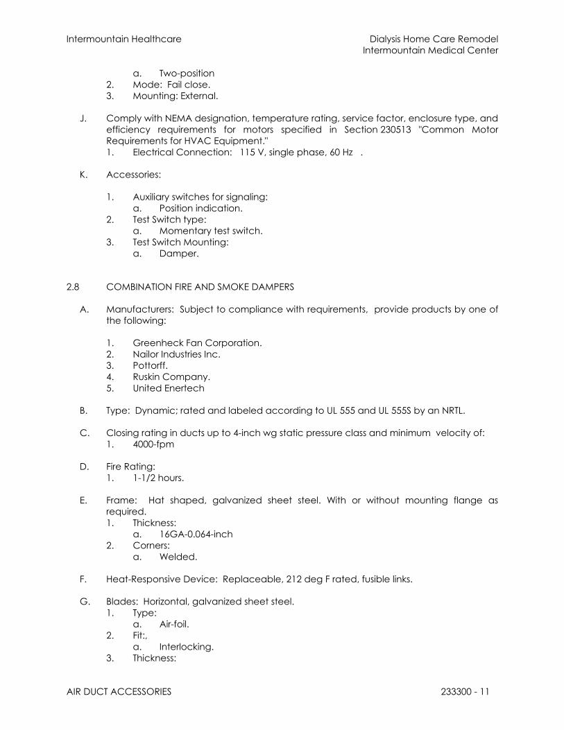
Intermountain Healthcare Dialysis Home Care Remodel
Intermountain Medical Center
AIR DUCT ACCESSORIES 233300 - 11
a. Two-position
2. Mode: Fail close.
3. Mounting: External.
J. Comply with NEMA designation, temperature rating, service factor, enclosure type, and
efficiency requirements for motors specified in Section 230513 "Common Motor
Requirements for HVAC Equipment."
1. Electrical Connection: 115 V, single phase, 60 Hz .
K. Accessories:
1. Auxiliary switches for signaling:
a. Position indication.
2. Test Switch type:
a. Momentary test switch.
3. Test Switch Mounting:
a. Damper.
2.8 COMBINATION FIRE AND SMOKE DAMPERS
A. Manufacturers: Subject to compliance with requirements, provide products by one of
the following:
1. Greenheck Fan Corporation.
2. Nailor Industries Inc.
3. Pottorff.
4. Ruskin Company.
5. United Enertech
B. Type: Dynamic; rated and labeled according to UL 555 and UL 555S by an NRTL.
C. Closing rating in ducts up to 4-inch wg static pressure class and minimum velocity of:
1. 4000-fpm
D. Fire Rating:
1. 1-1/2 hours.
E. Frame: Hat shaped, galvanized sheet steel. With or without mounting flange as
required.
1. Thickness:
a. 16GA-0.064-inch
2. Corners:
a. Welded.
F. Heat-Responsive Device: Replaceable, 212 deg F rated, fusible links.
G. Blades: Horizontal, galvanized sheet steel.
1. Type:
a. Air-foil.
2. Fit:,
a. Interlocking.
3. Thickness:

Intermountain Healthcare Dialysis Home Care Remodel
Intermountain Medical Center
AIR DUCT ACCESSORIES 233300 - 12
a. 0.063-inch-.
H. Leakage:
1. Class I.
I. Rated pressure and velocity to exceed design airflow conditions.
J. Mounting Sleeve: Factory-installed, galvanized sheet steel; length to suit wall or floor
application with factory-furnished silicone calking.
1. Thickness:
a. 18GA 0.05-inch-.
K. Master control panel for use in dynamic smoke-management systems.
L. Damper Motors: Damper motors to be Belimo or approved equal. Honeywell motors
are not allowed.
1. Locate outside air stream unless otherwise indicated,
2. Action:
a. Two-position.
3. Voltage: to match fire alarm system (coordinate).
4. Listed: UL, as part of damper assembly.
5. Outdoor Motors and Motors in Outside-Air Intakes:
a. Gaskets: O-ring gaskets designed to make motors weatherproof.
b. Internal heaters: Equip to permit normal operation at minus 40 deg F .
M. Comply with NEMA designation, temperature rating, service factor, enclosure type, and
efficiency requirements for motors specified in Section 230513 "Common Motor
Requirements for HVAC Equipment."
1. Electrical Connection: 115 V, single phase, 60 Hz.
N. Accessories:
2. Auxiliary switches:
a. Signaling.
b. Position indication.
3. Test Switch type:
a. Momentary test switch.
4. Test Switch Mounting:
a. Damper.
2.9 TURNING VANES
A. Manufacturers: Subject to compliance with requirements, provide products by one of
the following:
1. METALAIRE, Inc.
2. SEMCO Incorporated.
3. Ward Industries, Inc.; a division of Hart & Cooley, Inc.
B. Manufactured Turning Vanes for Metal Ducts: Curved blades of galvanized sheet steel;
support with bars perpendicular to blades set; set into vane runners suitable for duct
mounting.

Intermountain Healthcare Dialysis Home Care Remodel
Intermountain Medical Center
AIR DUCT ACCESSORIES 233300 - 13
1. Fabricate single blade vanes to comply with SMACNA’s “HVAC Duct
Construction Standards-Metal and Flexible.”
2. Acoustic Turning Vanes: Fabricate airfoil-shaped aluminum extrusions with
perforated faces and fibrous-glass fill.
C. Manufactured Turning Vanes for Nonmetal Ducts: Fabricate curved blades of resin-
bonded fiberglass with acrylic polymer coating; support with bars perpendicular to
blades set; set into vane runners suitable for duct mounting.
D. General Requirements: Comply with SMACNA's "HVAC Duct Construction Standards -
Metal and Flexible"; Figures 4-3, "Vanes and Vane Runners," and 4-4, "Vane Support in
Elbows."
E. Vane Construction:
1. Single wall
F. Vane Spacing:
1. 1-1/2” spacing between turning vanes
2. 3-1/4” spacing not allowed.
G. Vane Construction: Single wall for ducts up to 36 inches wide and additional bracing
for larger dimensions.
2.10 REMOTE DAMPER OPERATORS
A. Manufacturers: Subject to compliance with requirements, provide products by one of
the following:
1. Pottorff.
2. Ruskin Company; Tomkins PLC.
B. Cable Type:
1. Description: Cable system designed for remote manual damper adjustment.
2. Tubing/Sheathing: Galvinsed, Brass, Copper or Aluminum.
3. Cable: Stainless steel or Steel.
4. Wall-Box Mounting: Coordinate with Architect.
5. Wall-Box Cover-Plate Material: Coordinate with Architect.
C. Activated Electric Type:
1. Description: Electrically activated zone control damper for remote adjustment.
When an adjustment is needed the system is powered up.
2. Means: Factory mounted actuator factory wired to damper.
3. Portable 9 volt system. No field power requirement.
4. Mounting: Recessed Wall Box or Diffuser or Hand Held.
5. Wall-Box Cover Finish: Coordinate with Architect.
6. Wall-Box Porting: 1 to 6 ports or more.

Intermountain Healthcare Dialysis Home Care Remodel
Intermountain Medical Center
AIR DUCT ACCESSORIES 233300 - 14
2.11 DUCT-MOUNTED ACCESS DOORS
A. Manufacturers: Subject to compliance with requirements, provide products by one of
the following:
1. Greenheck Fan Corporation.
2. McGill AirFlow LLC.
3. Pottorff.
4. Ward Industries, Inc.; a division of Hart & Cooley, Inc.
5. Ruskin Company
B. Duct-Mounted Access Doors: Fabricate access panels according to SMACNA's "HVAC
Duct Construction Standards - Metal and Flexible"; Figures 7-2, "Duct Access Doors and
Panels," and 7-3, "Access Doors - Round Duct."
1. Door:
a. Double wall, rectangular.
b. Galvanized sheet metal with insulation fill and thickness as indicated for
duct pressure class.
c. Hinges and Latches: 1-by-1-inch butt or piano hinge and cam latches.
d. Fabricate doors airtight and suitable for duct pressure class.
2. Frame: Galvanized sheet steel, with bend-over tabs and foam gaskets.
3. Number of Hinges and Locks:
a. Access Doors Less Than 12 Inches Square: No hinges and two sash locks.
b. Access Doors up to 18 Inches Square:
1) Hinges:
a) Two hinges and two sash locks.
c. Access Doors up to 24 by 48 Inches, provide outside and inside handles:
1) Hinges:
a) Three hinges and two compression latches.
d. Access Doors Larger Than 24 by 48 Inches, provide outside and inside
handles:
1) Hinges:
a) Continuous and two compression latches with outside and
inside handles.
2.12 FLEXIBLE CONNECTORS
A. Manufacturers: Subject to compliance with requirements, provide products by one of
the following:
1. Ductmate Industries, Inc.
2. Ventfabrics, Inc.
3. Ward Industries, Inc.; a division of Hart & Cooley, Inc.
B. Materials: Flame-retardant or noncombustible fabrics.
C. Coatings and Adhesives: Comply with UL 181, Class 1.

Intermountain Healthcare Dialysis Home Care Remodel
Intermountain Medical Center
AIR DUCT ACCESSORIES 233300 - 15
D. Metal-Edged Connectors: Factory fabricated with a wide fabric strip attached to two
narrower metal strips. Provide strips of metal compatible with connected ducts.
1. Wide Strip:
a. 3-1/2 inches.
2. Narrow Strips:
a. 0.028-inch- thick, galvanized sheet steel.
E. Indoor System, Flexible Connector Fabric: Glass fabric double coated with neoprene.
1. Minimum Weight: 26 oz./sq. yd..
2. Tensile Strength: 530 lbf/inch in the warp and 440 lbf/inch in the filling.
3. Service Temperature: Minus 40 to plus 200 deg F.
F. Outdoor System, Flexible Connector Fabric: Glass fabric double coated with
weatherproof, synthetic rubber resistant to UV rays and ozone.
1. Minimum Weight: 24 oz./sq. yd..
2. Tensile Strength: 530 lbf/inch in the warp and 440 lbf/inch in the filling.
3. Service Temperature: Minus 50 to plus 250 deg F.
2.13 FLEXIBLE DUCTS
A. Manufacturers: Subject to compliance with requirements, provide products by one of
the following:
1. Flexmaster U.S.A., Inc.
2. McGill AirFlow LLC.
3. Themaflex
4. Ward Industries, Inc.; a division of Hart & Cooley, Inc.
B. Ducts shall conform to the requirements for Class I connectors when tested in
accordance with "Standard for Factory Made Air Ducts Materials and Air Duct
Connectors" (UL 181).
C. Ducts shall also pass the 15 minute U.L. flame penetration test as specified in the UL 181
Standard.
D. Insulated, Flexible Duct: Two-ply vinyl film supported by helically wound, spring-steel
wire; fibrous-glass insulation; polyethylene or aluminized vapor-barrier film.
1. Pressure Rating: 10-inch wg positive and 1.0-inch wg negative.
2. Maximum Air Velocity: 4000 fpm.
3. Temperature Range: Minus 10 to plus 160 deg F.
4. Insulation R-value: Comply with ASHRAE/IESNA 90.1.
E. Flexible Duct Connectors:
1. Clamps: in sizes 3 through 18 inches, to suit duct size.
a. Material: Stainless-steel band with cadmium-plated hex screw to tighten
band with a worm-gear action.

Intermountain Healthcare Dialysis Home Care Remodel
Intermountain Medical Center
AIR DUCT ACCESSORIES 233300 - 16
2.14 DUCT ACCESSORY HARDWARE
A. Instrument Test Holes: Cast iron or cast aluminum to suit duct material, including screw
cap and gasket. Size to allow insertion of pitot tube and other testing instruments and
of length to suit duct-insulation thickness.
B. Adhesives: High strength, quick setting, neoprene based, waterproof, and resistant to
gasoline and grease.
C. Splitter Damper Accessories: Zinc-plated damper blade bracket; 1/4-inch, zinc-plated
operating rod; and a duct-mounted, ball-joint bracket with flat rubber gasket and
square-head set screw.
D. Flexible Duct Clamps: Stainless-steel band with cadmium-plated hex screw to tighten
band with a worm-gear action, in sizes 3 to 18 inches to suit duct size.
2.15 HIGH EFFICIENCY TAKE-OFFS
A. Manufacturers: Subject to compliance with requirements, provide products by one of
the following.
1. Air-Rite
2. Hercules Industries
3. Sheet Metal Connectors, Inc.
4. Spiral Manufacturing Co. Inc.
5. Ferguson
B. Materials:
1. 24 gauge galvanized sheet metal meeting ASTM A653 and A924
C. Take-off shall meet SMACNA third edition Section 4.8 figure 4.6 - 45 degree entry.
D. Rectangular opening with flanged sides on all sides. Complete with closed cell neo-
prene gasket
to provide a tight seal.
E. Zeros VOC’s
PART 3 - EXECUTION
3.1 INSTALLATION
General
A. Install duct accessories according to applicable details in SMACNA's "HVAC Duct
Construction Standards - Metal and Flexible" for metal ducts and in NAIMA AH116,
"Fibrous Glass Duct Construction Standards," for fibrous-glass ducts.

Intermountain Healthcare Dialysis Home Care Remodel
Intermountain Medical Center
AIR DUCT ACCESSORIES 233300 - 17
B. Install duct accessories of materials suited to duct materials; use galvanized-steel
accessories in galvanized-steel and fibrous-glass ducts, stainless-steel accessories in
stainless-steel ducts, and aluminum accessories in aluminum ducts.
C. Use the Remote Damper Operator when they are called out on the drawings or when
the damper cannot be easily accessed.
D. Install duct security bars. Construct duct security bars from 3/16-inch steel sleeve,
continuously welded at all joints and 3/4-inch- diameter steel bars, 6 inches o.c. in each
direction in center of sleeve. Weld each bar to steel sleeve and each crossing bar.
Weld 1-1/2-by-1-1/2-by-1/8- steel angle to 4 sides and both ends of sleeve. Connect
duct security bars to ducts with flexible connections. Provide 12-by-12-inch hinged
access panel with cam lock in duct in each side of sleeve.
E. Install high efficiency take-off on all branch duct take-offs. Provide take-off with
balancing damper as shown on drawings. Spin-in fittings are not allowed.
Flexible Ducts / Flexible Duct Connectors
F. Install flexible connectors to connect ducts to equipment.
G. Flexible duct connections from the main trunk ducts to diffuser boots shall be furnished
and installed as shown on the drawings. Flexible ductwork shall only be used as
indicated on the drawings.
H. Where flexible duct is indicated, use insulated flexible duct for supply air return and
exhaust air.
I. Flexible ductwork shall be run in straight lengths.
J. Provide support in flexible duct every three feet.
K. Flexible ducts shall have compression fittings on both ends.
L. Flexible ductwork is not allowed to bend 90 degrees. If a bend is needed use sheet-
metal hard elbows. Hard turns, offsets, or kinks will not be allowed.
M. Flexible ducts shall connect to trunk duct with high efficiency takeoffs.
N. Connect flexible ducts to metal ducts with draw bands.
O. Connect ducts to duct silencers:
1. With flexible duct connectors.
P. Connect terminal units to supply ducts:
1. With maximum 12-inch lengths of flexible duct.
Q. Do not use flexible ducts to change directions.
R. Connect diffusers or light troffer boots to ducts:
1. With maximum 60-inch lengths of flexible duct clamped or strapped in place.
Backdraft/Control/Pressure Relief Dampers

Intermountain Healthcare Dialysis Home Care Remodel
Intermountain Medical Center
AIR DUCT ACCESSORIES 233300 - 18
S. Install backdraft dampers at inlet of exhaust fans or exhaust ducts as close as possible
to exhaust fan unless otherwise indicated.
T. Install pressure relief damper immediately upstream of main fire damper.
Volume Damper
U. Install volume dampers at points on supply, return, and exhaust systems where
branches extend from larger ducts. Where dampers are installed in ducts having duct
liner, install dampers with hat channels of same depth as liner, and terminate liner with
nosing at hat channel.
1. Install steel volume dampers in steel ducts.
2. Install aluminum volume dampers in aluminum ducts.
V. Set dampers to fully open position before testing, adjusting, and balancing. Exception:
Pressure relief damper.
W. A balance damper with locking quadrant will be provided downstream of take-off from
trunk duct.
Fans And Test Holes
X. For fans developing static pressures of 5-inch wg and more, cover flexible connectors
with loaded vinyl sheet held in place with metal straps.
Y. Install thrust limits at centerline of thrust, symmetrical on both sides of equipment.
Attach thrust limits at centerline of thrust and adjust to a maximum of 1/4-inch
movement during start and stop of fans.
Z. Install duct test holes where required for testing and balancing purposes.
AA. Install test holes at fan inlets and outlets and elsewhere as indicated.
FIRE, SMOKE AND FIRE-SMOKE DAMPERS
BB. Install fire and smoke dampers according to UL listing.
1. Install fusible links in fire dampers.
CC. For round ductwork 24-inch and smaller a true round fire damper with the same rating
may be used.
Access Doors
DD. Install duct access doors on sides of ducts to allow for inspecting, adjusting, and
maintaining accessories and equipment at the following locations:
1. On upstream side of duct coils.
2. Upstream from duct filters.
3. At outdoor-air intakes and mixed-air plenums.
4. At drain pans and seals.
5. Downstream from manual volume dampers, control dampers, backdraft
dampers, and equipment.

Intermountain Healthcare Dialysis Home Care Remodel
Intermountain Medical Center
AIR DUCT ACCESSORIES 233300 - 19
6. Adjacent to and close enough to fire or smoke dampers, to reset or reinstall
fusible links. Access doors for access to fire or smoke dampers having fusible links
shall be standard access doors and shall be outward operation for access
doors installed upstream from dampers and inward operation for access doors
installed downstream from dampers.
7. At each change in direction and at maximum 50-foot spacing.
8. Upstream from turning vanes.
9. Upstream or downstream from duct silencers.
10. Control devices requiring inspection.
11. Elsewhere as indicated.
12. On upstream side of duct reheat coils. (between Phoenix valve and reheat coil)
EE. Install access doors with swing against duct static pressure.
FF. Access Door Sizes:
1. One-Hand or Inspection Access: 8 by 5 inches.
2. Two-Hand Access: 12 by 6 inches.
3. Head and Hand Access: 18 by 10 inches.
4. Head and Shoulders Access: 21 by 14 inches.
5. Body Access: 25 by 14 inches.
6. Body plus Ladder Access: 25 by 17 inches.
GG. Label access doors according to Section 230553 "Identification for HVAC Piping and
Equipment" to indicate the purpose of access door.
3.2 FIELD QUALITY CONTROL
A. Tests and Inspections:
1. Operate dampers to verify full range of movement.
2. Inspect locations of access doors and verify that purpose of access door can be
performed.
3. Operate fire, smoke, and combination fire and smoke dampers to verify full range
of movement and verify that proper heat-response device is installed.
4. Inspect turning vanes for proper and secure installation.
5. Operate remote damper operators to verify full range of movement of operator
and damper.
3.3 ADJUSTING
A. Adjust duct accessories for proper settings.
B. Adjust fire and smoke dampers for proper action.
C. Final positioning of manual-volume dampers is specified in Division 23 Section "Testing,
Adjusting, and Balancing for HVAC."
END OF SECTION 233300

Intermountain Healthcare Dialysis Home Care Remodel
Intermountain Medical Center
DIFFUSERS, REGISTERS, AND GRILLES 233713 - 1
SECTION 233713 - DIFFUSERS, REGISTERS, AND GRILLES
PART 1 - GENERAL
1.1 RELATED DOCUMENTS
A. Drawings and general provisions of the Contract, including General and
Supplementary Conditions and Division 01 Specification Sections, apply to this Section.
1.2 SUMMARY
A. This section includes ceiling- and wall-mounted diffusers, registers, and grilles.
B. Related Sections:
1. Section 233714 "Fixed Louvers" for fixed and louvers and wall vents, whether or not
they are connected to ducts.
2. Section 233300 "Air Duct Accessories" for fire and smoke dampers and volume-
control dampers not integral to diffusers, registers, and grilles.
3. Section 230594 "General Testing, Adjusting and Balancing" for balancing diffusers,
registers, and grilles.
1.3 ACTION SUBMITTALS
A. Product Data: For each type of product indicated, include the following:
1. Data Sheet: Indicate materials of construction, finish, and mounting details; and
performance data including throw and drop, static-pressure drop, and noise
ratings.
2. Diffuser, Register, and Grille Schedule: Indicate drawing designation, room
location, quantity, model number, size, and accessories furnished.
1.4 INFORMATIONAL SUBMITTALS
A. Coordination Drawings: Reflected ceiling plans, drawn to scale, on which the following
items are shown and coordinated with each other, using input from Installers of the
items involved:
1. Ceiling suspension assembly members.
2. Method of attaching hangers to building structure.
3. Size and location of initial access modules for acoustical tile.
4. Ceiling-mounted items including lighting fixtures, diffusers, grilles, speakers,
sprinklers, access panels, and special moldings.
5. Duct access panels.
B. Source quality-control reports.

Intermountain Healthcare Dialysis Home Care Remodel
Intermountain Medical Center
DIFFUSERS, REGISTERS, AND GRILLES 233713 - 2
1.5 QUALITY ASSURANCE
A. Product Options: Drawings and schedules indicate specific requirements of diffusers,
registers, and grilles and are based on the specific requirements of the systems
indicated.
B. NFPA Compliance: Install diffusers, registers, and grilles according to NFPA 90A,
"Standard for the Installation of Air-Conditioning and Ventilating Systems."
C. Airborne Noise:
1. Comply with ANSI / AHRI 880 - Performance Rating of Air Terminals
PART 2 - PRODUCTS
2.1 MANUFACTURERS
A. Manufacturers: Subject to compliance with requirements, provide products by one of
the following:
1. Air Factors
2. Carnes.
3. Kruegar.
4. METALAIRE, Inc.
5. Nailor Industries Inc.
6. Price Industries.
7. Titus.
8. Tuttle & Bailey.
2.2 REGISTERS, GRILLES, & DIFFUSERS
A. General: The frames for all registers, grilles, and diffusers shall match type of ceiling
where they are to be installed. Special frames shall be provided for narrow T-bar
ceilings. Refer to reflected ceiling plan and other specification divisions for ceiling type.
See drawings AND schedules for additional information.
2.3 SOURCE QUALITY CONTROL
A. Verification of Performance: Rate diffusers, registers, and grilles according to
ASHRAE 70, "Method of Testing for Rating the Performance of Air Outlets and Inlets."
PART 3 - EXECUTION
3.1 EXAMINATION
A. Examine areas where diffusers, registers, and grilles are to be installed for compliance

Intermountain Healthcare Dialysis Home Care Remodel
Intermountain Medical Center
DIFFUSERS, REGISTERS, AND GRILLES 233713 - 3
with requirements for installation tolerances and other conditions affecting
performance of equipment.
B. Proceed with installation only after unsatisfactory conditions have been corrected.
3.2 INSTALLATION
A. Install diffusers, registers, and grilles level and plumb, according to manufacturer's
written instructions, coordination drawings, original design, and referenced standards.
B. Ceiling-Mounted Outlets and Inlets: Drawings indicate general arrangement of ducts,
fittings, and accessories. Air outlet and inlet locations have been indicated to achieve
design requirements for air volume, noise criteria, airflow pattern, throw, and pressure
drop. Make final locations where indicated, as much as practical. For units installed in
lay-in ceiling panels, locate units in the center of panel. Where architectural features or
other items conflict with installation, notify Architect for a determination of final
location.
C. Install diffusers, registers, and grilles with airtight connections to ducts and to allow
service and maintenance of dampers, air extractors, and fire dampers.
3.3 ADJUSTING
A. After installation, adjust diffusers, registers, and grilles to air patterns indicated, or as
directed, before starting air balancing.
3.4 CLEANING
A. After installation of diffusers, registers, and grilles, inspect exposed finish. Clean exposed
surfaces to remove burrs, dirt, and smudges. Replace diffusers, registers, and grilles that
have damaged finishes.
END OF SECTION 233713

Division Section Title Pages
SPECIFICATIONS GROUP
Facility Services Subgroup
DIVISION 26 - ELECTRICAL260519 LOW-VOLTAGE ELECTRICAL POWER CONDUCTORS AND CABLES 7260529 HANGERS AND SUPPORTS FOR ELECTRICAL SYSTEMS 6260533 RACEWAYS AND BOXES FOR ELECTRICAL SYSTEMS 10260544 SLEEVES AND SLEEVE SEALS FOR ELECTRICAL RACEWAYS AND
CABLING 4
260553 IDENTIFICATION FOR ELECTRICAL SYSTEMS 7260923 IGHTING CONTROL DEVICES 9265119 LED INTERIOR LIGHTING 12
DIVISION 27 - COMMUNICATIONS270000 COMMON GENERAL CONDITIONS FOR COMMUNICATIONS SECTIONS 9270100 OPERATION+MAINTENANCE OF COMMUNICATION SYSTEMS 2270113 WARRANTY, PRODUCT AND SYSTEM 2270119 FIELD TESTING AND REPORTING 5270133 SHOP DRAWINGS, PRODUCT DATA, SAMPLES DESIGN RECORDS &
EXISTING CONDITIONS 3
270143 QUALIFICATIONS AND REQUIRED TRAINING FOR CONTRACTOR AND INSTALLER
1
270171 RESPONSIBILITY AND WORKMANSHIP OF CONTRACTOR 2270500 COMMON WORK RESULTS FOR COMMUNICATONS 2270526 GROUNDING AND BONDING FOR COMMUNICATIONS SYSTEMS 2270528 PATHWAYS FOR COMMUNICATIONS SYSTEMS 4270529 HANGERS AND SUPPORTS FOR COMMUNICATION SYSTEMS 1270533 CONDUITS AND BACK BOXES FOR COMMUNICATION SYSTEMS 1270536 CABLE TRAYS FOR COMMUNICATIONS SYSTEMS 6270543 CAMPUS CABLE ROUTING 1270553 IDENTIFICATION FOR LOW-VOLTAGE CABLES AND LABELING 3271119 TERMINATION BLOCKS AND PATCH PANELS 2271500 HORIZONTAL CABLING 4271513 COPPER CABLE 1271543 FACEPLATES AND CONNECTORS 2271619 PATCH CABLES 1275223 NURSE CALL 10

276001 APPENDIX 01 DEVIATION REQUEST PROCESS 2276002 APPENDIX 02 DOCUMENT REFRESH PROCESS 1276003 APPENDIX 03 DATA CENTER, TEC, TDR PART NUMBERS 2276004 APPENDIX 04 REFERENCE STANDARDS 2276005 APPENDIX 05 DEFINITIONS AND ABBREVIATIONS 2276006 APPENDIX 06 MATERIAL SUPPLIERS 1276007 APPENDIX 07 SIEMON - CERTIFIED INSTALLATION FIRMS 4276008 APPENDIX 08 LEAD WALL PENETRATIONS 2
END OF TABLE OF CONTENTS
Intermountain Healthcare Dialysis Home Care RemodelIntermountain Medical Center
LOW-VOLTAGE ELECTRICAL POWER CONDUCTORS AND CABLES 26 05 19 - 1
SECTION 26 05 19 - LOW-VOLTAGE ELECTRICAL POWER CONDUCTORS AND CABLES
PART 1 - GENERAL
1.1 RELATED DOCUMENTS
A. Drawings and general provisions of the Contract, including General and Supplementary Conditions and Division 01 Specification Sections, apply to this Section.
1.2 SUMMARY
A. Section Includes:1. Building wires and cables rated 600 V and less.2. Connectors, splices, and terminations rated 600 V and less.
B. Related Requirements:1. Section 26 05 33 “Raceways and Boxes for Electrical Systems”2. Section 26 09 23 “Lighting Control Devices” 3. Section 26 09 36 “Standalone Modular Preset Dimming Controls”4. Section 26 09 43 “Relay-Based Lighting Controls”5. Section 27 41 33 “Master Antenna Television System”6. Section 27 51 17 “Networked Public Address and Paging System”7. Section 27 51 19 “Sound Masking Systems”8. Section 28 13 00 “Access Control”9. Section 28 31 11 “Digital, Addressable Fire-Alarm System”10. Section 27 00 00 "Intermountain Healthcare Networked Structured Cable & Standards"
for cabling used for voice and data circuits.
1.3 DEFINITIONS
A. Outlet Box: Electrical box used to support utilization equipment such as a receptacle or light fixture.
B. Pull Box: Electrical box through which branch circuit or feeder conductors are run but are not spliced.
C. Junction Box: Electrical box used for splicing branch circuit or feeder conductors.
D. Multiwire Branch Circuit: A branch circuit as defined by the National Electrical Code that shares a grounded conductor between two of more phase conductors.
1.4 ACTION SUBMITTALS
A. Product Data: For each type of product.

Intermountain Healthcare Dialysis Home Care RemodelIntermountain Medical Center
LOW-VOLTAGE ELECTRICAL POWER CONDUCTORS AND CABLES 26 05 19 - 2
1.5 INFORMATIONAL SUBMITTALS
A. Field quality-control reports.
PART 2 - PRODUCTS
2.1 SINGLE CONDUCTORS
A. Manufacturers: Subject to compliance with requirements, available manufacturers offering products that may be incorporated into the Work include, but are not limited to the following:1. Alpha Wire Company.2. Belden Inc.3. Cerro Wire LLC.4. Encore Wire Corporation.5. General Cable; General Cable Corporation.6. Southwire Company.7. Thomas & Betts Corporation; A Member of the ABB Group.
B. Aluminum and Copper Conductors: Comply with NEMA WC 70/ICEA S-95-658.
C. Conductor Insulation: Comply with NEMA WC 70/ICEA S-95-658 for Type THHN/THWN-2, Type XHHW-2 and Type SO.
2.2 MULTI-CONDUCTOR CABLES
A. Manufacturers: Subject to compliance with requirements, available manufacturers offering products that may be incorporated into the Work include, but are not limited to the following:1. Southwire Company.2. AFC Cable Systems.
B. Copper Conductors: Comply with NEMA WC 70/ICEA S-95-658.
C. Conductor Insulation: Comply with NEMA WC 70/ICEA S-95-658 for Type THHN/THWN-2, Type XHHW-2 and Type SO.
D. Multi-conductor Cable, Type AC-HCF: 1. Armor: Galvanized Interlocking Steel Strip (green striped or solid green).2. Conductors: Solid Copper3. Conductor Insulation: THHN-2 with individual moisture resistant, fire retardant paper
wrap on each individual conductor.4. Grounding: 16 AWG integral bond wire and insulated green copper grounding
conductor.5. Neutral(Grounded) Conductor: White for 120Y/208 volt systems and Grey 480Y/277 volt
systems.6. Maximum Voltage Rating: 600 volts.7. References and Ratings:
a. UL 4, 83, 1479, 1581, 2556, File Reference E7330b. NEC 250.118(8), 300.22(C), 392, 320, 517.13, 518, 645

Intermountain Healthcare Dialysis Home Care RemodelIntermountain Medical Center
LOW-VOLTAGE ELECTRICAL POWER CONDUCTORS AND CABLES 26 05 19 - 3
c. Federal Specification A-A–59544 (formerly J-C–30B)d. UL Classified 1, 2, and 3-hour through (Fire) penetration product, R–14141e. Environmental Air-Handling Space Installation per NEC 300.22(C)
E. Other Multi-conductor Cable: Comply with NEMA WC 70/ICEA S-95-658 for Type SO with ground wire.
2.3 CONNECTORS AND SPLICES
A. Manufacturers: Subject to compliance with requirements, available manufacturers offering products that may be incorporated into the Work include, but are not limited to the following:1. 3M.2. AFC Cable Systems; a part of Atkore International.3. Hubbell Power Systems, Inc.4. Ideal Industries, Inc.5. ILSCO.6. O-Z/Gedney; a brand of Emerson Industrial Automation.
B. Description: Factory-fabricated connectors and splices of size, ampacity rating, material, type, and class for application and service indicated.
2.4 CORD REELS
A. Manufacturers: Subject to compliance with requirements, available manufacturers offering products that may be incorporated into the Work include, but are not limited to the following:1. APC Group; Kitchen Leash
B. Case (housing): 1. Dimensions: 9” x 12” x 3’2. Material: Molded Polypropylene 3.175 mm thickness3. 94v-2 flammability rating
C. Power Cord1. Conductors: 14/3 AWG copper type SJOW2. Length: 10 feet3. Rating: 200 degrees F
D. Receptacle/Plug1. Rated: 125vac/20 amp2. Receptacle: NEMA 5-15P3. Plug: Dual Duplex rated 20 amp
E. Mounting Bracket: Designed for installation on the ceiling type where the cord reel will be installed.

Intermountain Healthcare Dialysis Home Care RemodelIntermountain Medical Center
LOW-VOLTAGE ELECTRICAL POWER CONDUCTORS AND CABLES 26 05 19 - 4
2.5 SYSTEM DESCRIPTION
A. Electrical Components, Devices, and Accessories: Listed and labeled as defined in NFPA 70, by a qualified testing agency, and marked for intended location and application.
B. Comply with NFPA 70.
PART 3 - EXECUTION
3.1 CONDUCTOR MATERIAL APPLICATIONS
A. Feeders: Copper for feeders smaller than No. 4 AWG; for feeders No. 4 AWG and larger provide copper feeders unless aluminum is specifically indicated on the one-line diagrams. Solid or stranded for No. 10 AWG and smaller; stranded for No. 8 AWG and larger.
B. Branch Circuits: Copper. Solid or stranded for No. 10 AWG and smaller; stranded for No. 8 AWG and larger.
3.2 CONDUCTOR INSULATION AND MULTICONDUCTOR CABLE APPLICATIONS AND WIRING METHODS
A. Refer to Section 26 05 33 “Raceways and Boxes for Electrical Systems” for raceway types and applications.
B. Exposed Feeders: Type THHN/THWN-2, single conductors in raceway.
C. Feeders Concealed in Ceilings, Walls, Partitions, and Crawlspaces: Type THHN/THWN-2, single conductors in raceway.
D. Feeders below Slabs-On-Grade, and Underground: Type THWN-2, single conductors in raceway.
E. Multiwire Circuits: may not be used for branch circuit wiring. All 120 volt and 277 volt circuits shall be provided with a dedicated grounded conductor (neutral) for each phase conductor. Up to three of these circuits may be installed in a single conduit but not more than one conductor of each phase may be installed in a single conduit. Specification Writer’s Comment – Installation of more than 3 circuits in a homerun conduit, as a Value Engineering possibility, has been discussed with the Design-Assist Electrical Contractor but has not yet been approved.
F. Branch Circuits Concealed in Ceilings, Walls, and Partitions: Type THHN/THWN-2, single conductors in raceway. 1. Armored cable, Type AC-HCF may be installed for normal and equipment system single
branch circuits concealed in walls, and partitions in lengths between outlet boxes 30’ or less and not as homeruns or wiring between pullboxes or junction boxes.
2. Armored cable, Type AC-HCF may be installed between the first outlet box concealed in a wall or partition and a junction box above an accessible ceiling
Intermountain Healthcare Dialysis Home Care RemodelIntermountain Medical Center
LOW-VOLTAGE ELECTRICAL POWER CONDUCTORS AND CABLES 26 05 19 - 5
immediately above the location where the cable exits the wall or partition framing.
G. Branch Circuits below Slabs-on-Grade and Underground: Type THHN/THWN-2, single conductors in raceway. Installation of raceways within any concrete slab or composite concrete and steel deck is prohibited. NEC 517.13 (A) requires that all branch circuits serving patient care areas are provided with an effective ground-fault current path by installation in a metal raceway system, or a cable having a metallic armor or sheath assembly that qualifies as an equipment grounding conductor. Metallic raceways are not a specified raceway for branch circuits installed below slabs-on-grade. To assure compliance with the NEC requirement, both initially and when remodels occur in the future, the installation of branch circuit wiring under slabs-on-grade is limited to circuits supplying only the following rooms and area types without extension beyond the room or area to a room or area not listed here:1. Mechanical Spaces.2. Electrical Rooms.3. Food Service.
H. Branch circuit wiring may also be installed under slabs-on-grade to supply power for the following: 1. Systems Furniture.2. Floor Boxes.3. Direct wired equipment that is not located against a wall.
I. Cord Drops and Portable Appliance Connections: Type SO, hard service cord with stainless-steel, wire-mesh, strain-relief device at terminations to suit application.
J. Isolated Power System Conductors: #10 AWG, Type XHHW-2 stranded with cross-linked PE insulation and a dielectric constant of 3.5 or less, installed in EMT conduit.
3.3 INSTALLATION OF CONDUCTORS AND CABLES
A. Conceal cables in finished walls, ceilings, and floors unless otherwise indicated.
B. Complete raceway installation between conductor and cable termination points according to Section 26 05 33 "Raceways and Boxes for Electrical Systems" prior to pulling conductors and cables.
C. Use manufacturer-approved pulling compound or lubricant where necessary; compound used must not deteriorate conductor or insulation. Do not exceed manufacturer's recommended maximum pulling tensions and sidewall pressure values. Do not use pulling compounds or lubricant for installation of branch circuit conductors for Isolated Power Systems.
D. Use pulling means, including fish tape, cable, rope, and basket-weave wire/cable grips, that will not damage cables or raceway.
E. Install exposed cables parallel and perpendicular to surfaces of exposed structural members, and follow surface contours where possible.
F. Support cables according to Section 26 05 29 "Hangers and Supports for Electrical Systems."

Intermountain Healthcare Dialysis Home Care RemodelIntermountain Medical Center
LOW-VOLTAGE ELECTRICAL POWER CONDUCTORS AND CABLES 26 05 19 - 6
3.4 CORD REELS
A. Coordinate location of cord reels to align with kitchen equipment supplied by the cord reel.
B. Fasten brackets to structure using minimum 3/8” threaded rod and to rigidly support the cord real. Minimum of 2 rods per bracket with addition if required to provide a rigid support.
C. Adjust cord stopper as coordinated with owner.
3.5 CONNECTIONS
A. Tighten electrical connectors and terminals according to manufacturer's published torque-tightening values. If manufacturer's torque values are not indicated, use those specified in UL 486A-486B.
B. Make splices, terminations, and taps that are compatible with conductor material and that possess equivalent or better mechanical strength and insulation ratings than unspliced conductors.1. Use oxide inhibitor in each splice, termination, and tap for aluminum conductors.
C. Wiring at Outlets: Install conductor at each outlet, with at least 12 inches (300 mm) of slack.
3.6 IDENTIFICATION
A. Identify and color-code conductors and cables according to Section 26 05 53 "Identification for Electrical Systems."
B. Identify each spare conductor at each end with panel and circuit number and identify as spare conductor.
3.7 SLEEVE AND SLEEVE-SEAL INSTALLATION FOR ELECTRICAL PENETRATIONS
A. Install sleeves and sleeve seals at penetrations of exterior floor and wall assemblies. Comply with requirements in Section 26 05 44 "Sleeves and Sleeve Seals for Electrical Raceways and Cabling."
3.8 FIRESTOPPING
A. Apply firestopping to electrical penetrations of fire-rated floor and wall assemblies to restore original fire-resistance rating of assembly according to Section 07 84 13 "Penetration Firestopping."
3.9 FIELD QUALITY CONTROL
A. Perform the following tests and inspections:

Intermountain Healthcare Dialysis Home Care RemodelIntermountain Medical Center
LOW-VOLTAGE ELECTRICAL POWER CONDUCTORS AND CABLES 26 05 19 - 7
1. After installing conductors and cables and before electrical circuitry has been energized, test feeder conductors and conductors feeding the following critical equipment and services for compliance with requirements.a. Imaging Equipment
2. Infrared Scanning: After Substantial Completion, but not more than 60 days after Final Acceptance, perform an infrared scan of each splice in conductors No. 3 AWG and larger. Remove box and equipment covers so splices are accessible to portable scanner. Correct deficiencies determined during the scan.a. Follow-up Infrared Scanning: Perform an additional follow-up infrared scan of
each splice 11 months after date of Substantial Completion.b. Instrument: Use an infrared scanning device designed to measure temperature or
to detect significant deviations from normal values. Provide calibration record for device.
c. Record of Infrared Scanning: Prepare a certified report that identifies splices checked and that describes scanning results. Include notation of deficiencies detected, remedial action taken, and observations after remedial action.
B. Test and Inspection Reports: Prepare a written report to record the following:1. Procedures used.2. Results that comply with requirements.3. Results that do not comply with requirements and corrective action taken to achieve
compliance with requirements.
C. Cables will be considered defective if they do not pass tests and inspections.
END OF SECTION
Intermountain Healthcare Dialysis Home Care RemodelIntermountain Medical Center
HANGERS AND SUPPORTS FOR ELECTRICAL SYSTEMS26 05 29 - 1
SECTION 26 05 29 - HANGERS AND SUPPORTS FOR ELECTRICAL SYSTEMS
PART 1 - GENERAL
1.1 RELATED DOCUMENTS
A. Drawings and general provisions of the Contract, including General and Supplementary Conditions and Division 01 Specification Sections, apply to this Section.
1.2 SUMMARY
A. Section Includes:1. Hangers and supports for electrical equipment and systems.2. Construction requirements for concrete bases.
B. Related Requirements:1. Section 26 05 48.16 "Seismic Controls for Electrical Systems" for products and installation
requirements necessary for compliance with seismic criteria.
1.3 ACTION SUBMITTALS
A. Product Data: For each type of product.1. Include construction details, material descriptions, dimensions of individual components
and profiles, and finishes for the following:a. Hangers.b. Steel slotted support systems.c. Nonmetallic support systems.d. Trapeze hangers.e. Clamps.f. Turnbuckles.g. Sockets.h. Eye nuts.i. Saddles.j. Brackets.
2. Include rated capacities and furnished specialties and accessories.
B. Shop Drawings: Signed and sealed by a qualified professional engineer. For fabrication and installation details for electrical hangers and support systems.1. Trapeze hangers. Include product data for components.2. Steel slotted-channel systems.3.4. Nonmetallic slotted-channel systems.5. Equipment supports.6. Vibration Isolation Base Details: Detail fabrication, including anchorages and
attachments to structure and to supported equipment. Include adjustable motor bases, rails, and frames for equipment mounting.
C. Delegated-Design Submittal: For hangers and supports for electrical systems.

Intermountain Healthcare Dialysis Home Care RemodelIntermountain Medical Center
HANGERS AND SUPPORTS FOR ELECTRICAL SYSTEMS26 05 29 - 2
1. Include design calculations and details of trapeze hangers.2. Include design calculations for seismic restraints.
1.4 INFORMATIONAL SUBMITTALS
A. Coordination Drawings: Reflected ceiling plan(s) and other details, drawn to scale, on which the following items are shown and coordinated with each other, using input from installers of the items involved:1. Suspended ceiling components.2. Structural members to which hangers and supports will be attached.3. Size and location of initial access modules for acoustical tile.4. Items penetrating finished ceiling, including the following:
a. Lighting fixtures and lighting control.b. Electrical power devicesc. Communications devices.d. Air outlets and inlets.e. Speakers.f. Fire sprinklers.g. Access panels.h. Projectors.i. Fire alarm system devices.j. Nurse call system devices.
B. Seismic Qualification Certificates: For hangers and supports for electrical equipment and systems, accessories, and components, from manufacturer.1. Basis for Certification: Indicate whether withstand certification is based on actual test of
assembled components or on calculation.2. Dimensioned Outline Drawings of Equipment Unit: Identify center of gravity and locate
and describe mounting and anchorage provisions.3. Detailed description of equipment anchorage devices on which the certification is
based and their installation requirements.
C. Welding certificates.
1.5 QUALITY ASSURANCE
A. Welding Qualifications: Qualify procedures and personnel according to AWS D1.1/D1.1M.
PART 2 - PRODUCTS
2.1 PERFORMANCE REQUIREMENTS
A. Delegated Design: Engage a qualified professional engineer, as defined in Section 01 40 00 "Quality Requirements," to design hanger and support system.
B. Seismic Performance: Hangers and supports shall withstand the effects of earthquake motions determined according to ASCE/SEI 7.

Intermountain Healthcare Dialysis Home Care RemodelIntermountain Medical Center
HANGERS AND SUPPORTS FOR ELECTRICAL SYSTEMS26 05 29 - 3
1. The term "withstand" means "the supported equipment and systems will remain in place without separation of any parts when subjected to the seismic forces specified and the system will be fully operational after the seismic event."
2. Component Importance Factor: 1.5.
C. Surface-Burning Characteristics: Comply with ASTM E 84; testing by a qualified testing agency. Identify products with appropriate markings of applicable testing agency.1. Flame Rating: Class 1.2. Self-extinguishing according to ASTM D 635.
2.2 SUPPORT, ANCHORAGE, AND ATTACHMENT COMPONENTS
A. Steel Slotted Support Systems: Comply with MFMA-4 factory-fabricated components for field assembly.1. Material: Galvanized steel.2. Channel Width: Use 1-1/4 inches (31.75 mm) where possible and minimum 13/16 inches
(20.64 mm) where necessary due to space restrictions.3. Metallic Coatings: Hot-dip galvanized after fabrication and applied according to
MFMA-4.4. Channel Dimensions: Selected for applicable load criteria.
B. Conduit and Cable Support Devices: Steel hangers, clamps, and associated fittings, designed for types and sizes of raceway or cable to be supported.
C. Support for Conductors in Vertical Conduit: Factory-fabricated assembly consisting of threaded body and insulating wedging plug or plugs for electrical conductors in riser conduits. Plugs shall have number, size, and shape of conductor gripping pieces as required to suit individual conductors or cables supported. Body shall be made of malleable iron.
D. Structural Steel for Fabricated Supports and Restraints: ASTM A 36/A 36M steel plates, shapes, and bars; black and galvanized.
E. Mounting, Anchoring, and Attachment Components: Items for fastening electrical items or their supports to building surfaces include the following:1. Powder-Actuated Fasteners: Threaded-steel stud, for use in hardened portland cement
concrete, steel, or wood, with tension, shear, and pullout capacities appropriate for supported loads and building materials where used.
2. Mechanical-Expansion Anchors: Insert-wedge-type, stainless steel, for use in hardened portland cement concrete, with tension, shear, and pullout capacities appropriate for supported loads and building materials where used.
3. Concrete Inserts: Steel or malleable-iron, slotted support system units are similar to MSS Type 18 units and comply with MFMA-4 or MSS SP-58.
4. Clamps for Attachment to Steel Structural Elements: MSS SP-58 units are suitable for attached structural element.
5. Through Bolts: Structural type, hex head, and high strength. Comply with ASTM A 325.6. Hanger Rods: Threaded steel.
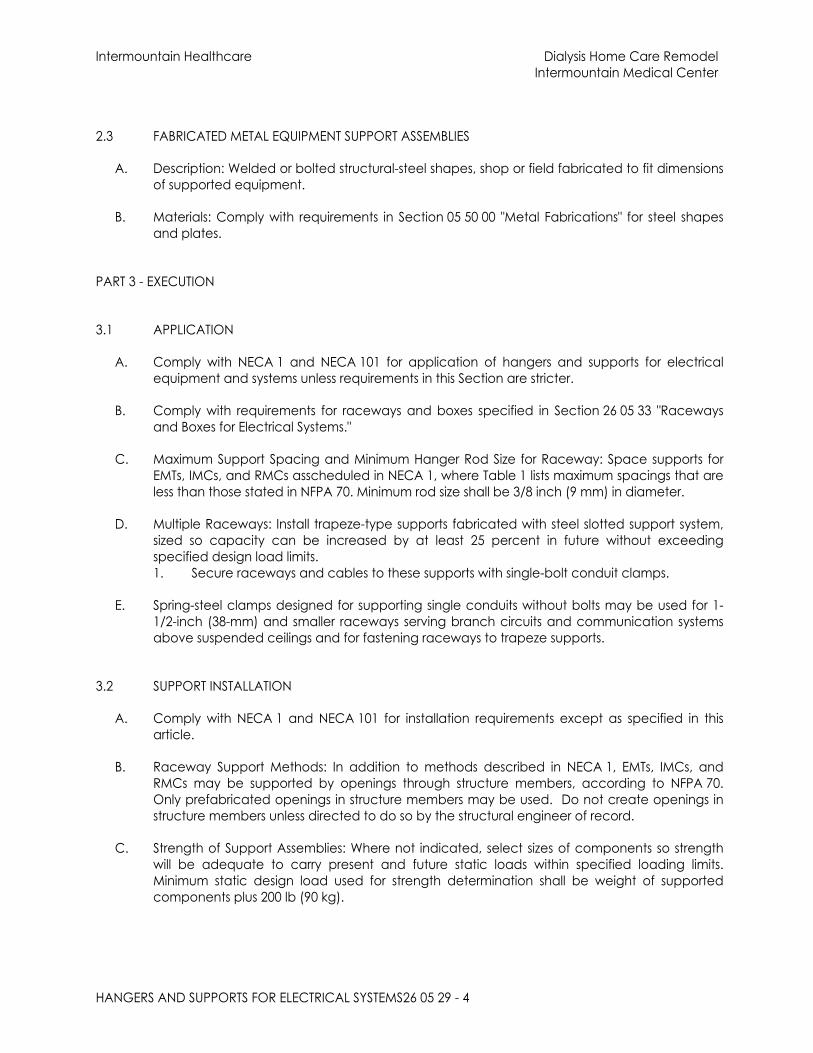
Intermountain Healthcare Dialysis Home Care RemodelIntermountain Medical Center
HANGERS AND SUPPORTS FOR ELECTRICAL SYSTEMS26 05 29 - 4
2.3 FABRICATED METAL EQUIPMENT SUPPORT ASSEMBLIES
A. Description: Welded or bolted structural-steel shapes, shop or field fabricated to fit dimensions of supported equipment.
B. Materials: Comply with requirements in Section 05 50 00 "Metal Fabrications" for steel shapes and plates.
PART 3 - EXECUTION
3.1 APPLICATION
A. Comply with NECA 1 and NECA 101 for application of hangers and supports for electrical equipment and systems unless requirements in this Section are stricter.
B. Comply with requirements for raceways and boxes specified in Section 26 05 33 "Raceways and Boxes for Electrical Systems."
C. Maximum Support Spacing and Minimum Hanger Rod Size for Raceway: Space supports for EMTs, IMCs, and RMCs asscheduled in NECA 1, where Table 1 lists maximum spacings that are less than those stated in NFPA 70. Minimum rod size shall be 3/8 inch (9 mm) in diameter.
D. Multiple Raceways: Install trapeze-type supports fabricated with steel slotted support system, sized so capacity can be increased by at least 25 percent in future without exceeding specified design load limits.1. Secure raceways and cables to these supports with single-bolt conduit clamps.
E. Spring-steel clamps designed for supporting single conduits without bolts may be used for 1-1/2-inch (38-mm) and smaller raceways serving branch circuits and communication systems above suspended ceilings and for fastening raceways to trapeze supports.
3.2 SUPPORT INSTALLATION
A. Comply with NECA 1 and NECA 101 for installation requirements except as specified in this article.
B. Raceway Support Methods: In addition to methods described in NECA 1, EMTs, IMCs, and RMCs may be supported by openings through structure members, according to NFPA 70. Only prefabricated openings in structure members may be used. Do not create openings in structure members unless directed to do so by the structural engineer of record.
C. Strength of Support Assemblies: Where not indicated, select sizes of components so strength will be adequate to carry present and future static loads within specified loading limits. Minimum static design load used for strength determination shall be weight of supported components plus 200 lb (90 kg).

Intermountain Healthcare Dialysis Home Care RemodelIntermountain Medical Center
HANGERS AND SUPPORTS FOR ELECTRICAL SYSTEMS26 05 29 - 5
D. Mounting and Anchorage of Surface-Mounted Equipment and Components: Anchor and fasten electrical items and their supports to building structural elements by the following methods unless otherwise indicated by code:1. To Wood: Fasten with lag screws or through bolts.2. To New Concrete: Bolt to concrete inserts.3. To Masonry: Approved toggle-type bolts on hollow masonry units and expansion anchor
fasteners on solid masonry units.4. To Existing Concrete: Expansion anchor fasteners.5. Instead of expansion anchors, powder-actuated driven threaded studs provided with
lock washers and nuts may be used in existing standard-weight concrete 4 inches (100 mm) thick or greater. Do not use for anchorage to lightweight-aggregate concrete or for slabs less than 4 inches (100 mm) thick.
6. To Steel: Beam clamps (MSS SP-58, Type 19, 21, 23, 25, or 27), complying with MSS SP-69.7. To Light Steel: Sheet metal screws.8. Items Mounted on Hollow Walls and Nonstructural Building Surfaces: Mount cabinets,
panelboards, disconnect switches, control enclosures, pull and junction boxes, transformers, and other devices on 13/16 inches (20.64 mm) slotted-channel racks attached to substrate by means that comply with seismic-restraint strength and anchorage requirements.
E. Drill holes for expansion anchors in concrete at locations and to depths that avoid the need for reinforcing bars.
3.3 INSTALLATION OF FABRICATED METAL SUPPORTS
A. Comply with installation requirements in Section 05 50 00 "Metal Fabrications" for site-fabricated metal supports.
B. Cut, fit, and place miscellaneous metal supports accurately in location, alignment, and elevation to support and anchor electrical materials and equipment.
C. Field Welding: Comply with AWS D1.1/D1.1M.
3.4 CONCRETE BASES
A. Construct concrete bases of dimensions indicated but not less than 4 inches (100 mm) larger in both directions than supported unit, and so anchors will be a minimum of 10 bolt diameters from edge of the base.
B. Use 3000-psi (20.7-MPa), 28-day compressive-strength concrete. Concrete materials, reinforcement, and placement requirements are specified in Section 03 30 00 "Cast-in-Place Concrete" or Section 03 30 53 "Miscellaneous Cast-in-Place Concrete."
C. Anchor equipment to concrete base as follows:1. Place and secure anchorage devices. Use supported equipment manufacturer's
setting drawings, templates, diagrams, instructions, and directions furnished with items to be embedded.
2. Install anchor bolts to elevations required for proper attachment to supported equipment.
3. Install anchor bolts according to anchor-bolt manufacturer's written instructions.

Intermountain Healthcare Dialysis Home Care RemodelIntermountain Medical Center
HANGERS AND SUPPORTS FOR ELECTRICAL SYSTEMS26 05 29 - 6
3.5 PAINTING
A. Touchup: Clean field welds and abraded areas of shop paint. Paint exposed areas immediately after erecting hangers and supports. Use same materials as used for shop painting. Comply with SSPC-PA 1 requirements for touching up field-painted surfaces.1. Apply paint by brush or spray to provide minimum dry film thickness of 2.0 mils (0.05
mm).
B. Touchup: Comply with requirements in Section 09 91 13 "Exterior Painting", Section 09 91 23 "Interior Painting" and Section 09 96 00 "High-Performance Coatings" for cleaning and touchup painting of field welds, bolted connections, and abraded areas of shop paint on miscellaneous metal.
C. Galvanized Surfaces: Clean welds, bolted connections, and abraded areas and apply galvanizing-repair paint to comply with ASTM A 780.
END OF SECTION

Intermountain Healthcare Dialysis Home Care RemodelIntermountain Medical Center
RACEWAYS AND BOXES FOR ELECTRICAL SYSTEMS26 05 33 - 1
SECTION 26 05 33 - RACEWAYS AND BOXES FOR ELECTRICAL SYSTEMS
PART 1 - GENERAL
1.1 RELATED DOCUMENTS
A. Drawings and general provisions of the Contract, including General and Supplementary Conditions and Division 01 Specification Sections, apply to this Section.
1.2 SUMMARY
A. Section Includes:1. Metal conduits, tubing, and fittings.2. Nonmetal conduits, tubing, and fittings.3. Metal wireways and auxiliary gutters.4. Surface raceways.5. Boxes, enclosures, and cabinets.6. Handholes and boxes for exterior underground cabling.
B. Related Requirements:1. Section 26 05 43 "Underground Ducts and Raceways for Electrical Systems" for
exterior ductbanks, manholes, and underground utility construction.
1.3 DEFINITIONS
A. ARC: Aluminum rigid conduit.
B. GRC: Galvanized rigid steel conduit.
C. IMC: Intermediate metal conduit.
1.4 ACTION SUBMITTALS
A. Product Data: For color coded EMT conduit, surface raceways, wireways and fittings, floor boxes, hinged-cover enclosures, and cabinets.
B. LEED Submittals:1. Product Data for Credit IEQ 4.1: For solvent cements and adhesive primers,
documentation including printed statement of VOC content.2. Laboratory Test Reports for Credit IEQ 4: For solvent cements and adhesive primers,
documentation indicating that products comply with the testing and product requirements of the California Department of Health Services' "Standard Practice for the Testing of Volatile Organic Emissions from Various Sources Using Small-Scale Environmental Chambers."
C. Shop Drawings: For custom enclosures and cabinets. Include plans, elevations, sections, and attachment details.

Intermountain Healthcare Dialysis Home Care RemodelIntermountain Medical Center
RACEWAYS AND BOXES FOR ELECTRICAL SYSTEMS26 05 33 - 2
D. Samples: For receptacle raceways and for each color and texture specified, 12 inches (300 mm) long.
1.5 INFORMATIONAL SUBMITTALS
A. Coordination Drawings: Conduit routing plans, drawn to scale, on which the following items are shown and coordinated with each other, using input from installers of items involved:1. Structural members in paths of conduit groups with common supports.2. HVAC and plumbing items and architectural features in paths of conduit groups with
common supports.
B. Qualification Data: For professional engineer.
C. Seismic Qualification Certificates: For enclosures, cabinets, and conduit racks and their mounting provisions, including those for internal components, from manufacturer.1. Basis for Certification: Indicate whether withstand certification is based on actual test
of assembled components or on calculation.2. Dimensioned Outline Drawings of Equipment Unit: Identify center of gravity and
locate and describe mounting and anchorage provisions.3. Detailed description of equipment anchorage devices on which the certification is
based and their installation requirements.4. Detailed description of conduit support devices and interconnections on which the
certification is based and their installation requirements.
D. Source quality-control reports.
PART 2 - PRODUCTS
2.1 METAL CONDUITS, TUBING, AND FITTINGS
A. Listing and Labeling: Metal conduits, tubing, and fittings shall be listed and labeled as defined in NFPA 70, by a qualified testing agency, and marked for intended location and application.
B. GRC: Comply with ANSI C80.1 and UL 6.
C. ARC: Comply with ANSI C80.5 and UL 6A.
D. IMC: Comply with ANSI C80.6 and UL 1242.
E. EMT: Comply with ANSI C80.3 and UL 797. Factory applied color finish available in black, orange, green, purple, red, yellow, blue, and white. Refer to Specification Section 26 05 53 “Identification for Electrical Systems” for color coding of raceways.
F. FMC: Comply with UL 1; zinc-coated steel.
G. LFMC: Flexible steel conduit with PVC jacket and complying with UL 360.
H. Fittings for Metal Conduit: Comply with NEMA FB 1 and UL 514B.

Intermountain Healthcare Dialysis Home Care RemodelIntermountain Medical Center
RACEWAYS AND BOXES FOR ELECTRICAL SYSTEMS26 05 33 - 3
1. Conduit Fittings for Hazardous (Classified) Locations: Comply with UL 886 and NFPA 70.
2. Fittings for EMT:a. Material: Steel.b. Type: compression.
3. Expansion Fittings: PVC or steel to match conduit type, complying with UL 651, rated for environmental conditions where installed, and including flexible external bonding jumper.
I. Joint Compound for IMC, GRC, or ARC: Approved, as defined in NFPA 70, by authorities having jurisdiction for use in conduit assemblies, and compounded for use to lubricate and protect threaded conduit joints from corrosion and to enhance their conductivity.
2.2 NONMETALLIC CONDUITS, TUBING, AND FITTINGS
A. Listing and Labeling: Nonmetallic conduits, tubing, and fittings shall be listed and labeled as defined in NFPA 70, by a qualified testing agency, and marked for intended location and application.
B. RNC: Type EPC-40-PVC, complying with NEMA TC 2 and UL 651 unless otherwise indicated.
C. LFNC: Comply with UL 1660.
D. Continuous HDPE: Comply with UL 651B.
E. RTRC: Comply with UL 1684A and NEMA TC 14.
F. Fittings for RNC: Comply with NEMA TC 3; match to conduit or tubing type and material.
G. Fittings for LFNC: Comply with UL 514B.
H. Solvent cements and adhesive primers shall have a VOC content of 510 and 550 g/L or less, respectively, when calculated according to 40 CFR 59, Subpart D (EPA Method 24).
I. Solvent cements and adhesive primers shall comply with the testing and product requirements of the California Department of Health Services' "Standard Practice for the Testing of Volatile Organic Emissions from Various Sources Using Small-Scale Environmental Chambers."
2.3 METAL WIREWAYS AND AUXILIARY GUTTERS
A. Description: Sheet metal, complying with UL 870 and NEMA 250, Type 1 unless otherwise indicated, and sized according to NFPA 70.1. Metal wireways installed outdoors shall be listed and labeled as defined in NFPA 70,
by a qualified testing agency, and marked for intended location and application.

Intermountain Healthcare Dialysis Home Care RemodelIntermountain Medical Center
RACEWAYS AND BOXES FOR ELECTRICAL SYSTEMS26 05 33 - 4
B. Fittings and Accessories: Include covers, couplings, offsets, elbows, expansion joints, adapters, hold-down straps, end caps, and other fittings to match and mate with wireways as required for complete system.
C. Wireway Covers: Hinged type unless otherwise indicated.
D. Finish: Manufacturer's standard enamel finish.
2.4 RECEPTACLE RACEWAYS
A. Listing and Labeling: Receptacle raceways shall be listed and labeled as defined in NFPA 70, by a qualified testing agency, and marked for intended location and application.
B. Surface Metal Raceways: Aluminum with snap-on covers complying with UL. Clear anodized finish.1. Raceways for receptacles only: Wiremold AL3300 series.2. Raceways for applications where both receptacles and data devices are installed in
the raceway and at all laboratory locations: Wiremold ALA4800 series two-channel and dual-cover. Satin anodized finish.
3. Provide duplex receptacles at 12 inches on center in all receptacle raceways. Provide GFCI receptacles as noted on drawings.
2.5 BOXES, ENCLOSURES, AND CABINETS
A. General Requirements for Boxes, Enclosures, and Cabinets: Boxes, enclosures, and cabinets installed in wet locations shall be listed for use in wet locations.
B. Sheet Metal Outlet and Device Boxes: Comply with NEMA OS 1 and UL 514A.
C. Cast-Metal Outlet and Device Boxes: Comply with NEMA FB 1, aluminum, Type FD, with gasketed cover.
D. Nonmetallic Outlet and Device Boxes: Comply with NEMA OS 2 and UL 514C.
E. Floor Boxes and Poke-Through Devices: Refer to Specification Section 26 27 26 “Wiring Devices” for floor boxes and poke-through devices
F. Luminaire Outlet Boxes: Nonadjustable, designed for attachment of luminaire weighing 50 lb (23 kg). Outlet boxes designed for attachment of luminaires weighing more than 50 lb (23 kg) shall be listed and marked for the maximum allowable weight.
G. Small Sheet Metal Pull and Junction Boxes: NEMA OS 1.
H. Cast-Metal Access, Pull, and Junction Boxes: Comply with NEMA FB 1 and UL 1773, cast aluminum with gasketed cover.
I. Box extensions used to accommodate new building finishes shall be of same material as recessed box.
J. Device Box Dimensions:

Intermountain Healthcare Dialysis Home Care RemodelIntermountain Medical Center
RACEWAYS AND BOXES FOR ELECTRICAL SYSTEMS26 05 33 - 5
1. Wiring Devices other than data or communications devices: Minimum 4 inches square by 2-1/8 inches deep with switch ring as required for the device configuration and wall or ceiling surface. Where light switches are indicated at a common location provide multi-gang boxes to accommodate the quantity and type of switches indicated. Where deeper boxes are required provide masonry type boxes which do not require a separate switch ring.
2. Data and communications devices: Minimum 4-11/16 inches square by 3 inches deep with single-gang 5/8 inch deep (or deeper if wall or ceiling finish is deeper) ring.
K. Pull boxes behind monitors: Minimum 6 inches square by 3-1/2 inches deep with two-gang ring.
L. Gangable boxes are prohibited.
M. Partitions: Provide partitions to separate emergency system conductors from conductors or other systems, where voltage between adjacent switches exceeds 300 volts and where switches controlling Low Voltage Controllers for interface to Nurse Call systems are installed in common boxes with line voltage switches.
N. Hinged-Cover Enclosures: Comply with UL 50 and NEMA 250.1. Indoor: Type 1 with continuous-hinge cover with flush latch unless otherwise
indicated. Steel, finished inside and out with manufacturer's standard enamel.2. Outdoor: Type 4X with continuous-hinge cover with flush latch unless otherwise
indicated. 304 stainless steel with smooth brushed finish.3. Interior Panels: Steel; all sides finished with manufacturer's standard enamel. Provide
interior panels when there are control devices or power blocks located inside the enclosure.
O. Handholes and Boxes for Exterior Underground Wiring: Refer to Specification Section 26 05 43 “Underground Ducts and Raceways for Electrical Systems”.
2.6 PUTTY PADS
A. Moldable intumescent wall opening-protective pads designed for application to the back of electrical outlet boxes prior to installation of the wall finish to provide up to 2-hour fire barrier ratings and minimum Sound Transmission Class (STC) of 52 when tested in an STC-53 rated wall assembly or 59 according to ASTM E90-97.
B. Manufacturers: Subject to compliance with requirements, provide products by one of the following:1. 3M Company.2. Hilti
PART 3 - EXECUTION
3.1 RACEWAY APPLICATION
A. Outdoors: Apply raceway products as specified below unless otherwise indicated:1. Exposed Conduit: GRC or IMC.

Intermountain Healthcare Dialysis Home Care RemodelIntermountain Medical Center
RACEWAYS AND BOXES FOR ELECTRICAL SYSTEMS26 05 33 - 6
2. Concealed Conduit, Aboveground: EMT.3. Underground Conduit for branch circuits: RNC, Type EPC-40-PVC, direct buried.4. Underground Conduit for feeders: Refer to Specification Section 26 05 43
“Underground Ducts and Raceways for Electrical Systems”.5. Raceways Embedded in slabs or composite steel and concrete decks are
prohibited.6. Connection to Vibrating Equipment (Including Transformers and Hydraulic,
Pneumatic, Electric Solenoid, or Motor-Driven Equipment): LFMC.7. Boxes and Enclosures, Aboveground: NEMA 250, Type 4X, 304 stainless steel.
B. Indoors: Apply raceway products as specified below unless otherwise indicated:1. Exposed, Not Subject to Physical Damage: EMT.2. Exposed, Not Subject to Severe Physical Damage: EMT.3. Exposed and Subject to Severe Physical Damage: GRC or IMC. Raceway locations
include the following:a. Loading dock.b. Corridors used for traffic of mechanized carts, forklifts, and pallet-handling
units.c. Mechanical rooms below 8 feet.d. Gymnasiums.
4. Concealed in Ceilings and Interior Walls and Partitions: EMT.5. Feeder Raceways under Slabs: RNC, Type EPC-40-PVC encased in not less than 2
inches of 3000 psi concrete. Change from RNC, Type EPC-40-PVC to GRC or IMC before rising above floor.
6. Branch Circuit Raceways under Slabs: Refer to Specifications Section 26 05 19 “Low-Voltage Electrical Power Conductors and Cables” for allowable application of under slab raceways. RNC, Type EPC-40-PVC direct buried. Change from RNC, Type EPC-40-PVC to GRC or IMC before rising above floor.
7. Raceways Embedded in slabs or composite steel and concrete decks are prohibited.
8. Connection to Vibrating Equipment (Including Transformers and Hydraulic, Pneumatic, Electric Solenoid, or Motor-Driven Equipment): FMC, except use LFMC in damp or wet locations.
9. Damp or Wet Locations: GRC or IMC.10. Boxes and Enclosures: NEMA 250, Type 1, except use NEMA 250, Type 4X, 304 stainless
steel in kitchens and damp or wet locations.11.
C. Minimum Raceway Size: 3/4-inch (21-mm) trade size.
D. Raceway Fittings: Compatible with raceways and suitable for use and location.1. Rigid and Intermediate Steel Conduit: Use threaded rigid steel conduit fittings unless
otherwise indicated. Comply with NEMA FB 2.10.2. EMT: Use setscrew or compression, steel fittings. Comply with NEMA FB 2.10.3. Flexible Conduit: Use only fittings listed for use with flexible conduit. Comply with
NEMA FB 2.20.
E. Install nonferrous conduit or tubing for circuits operating above 60 Hz. Where aluminum raceways are installed for such circuits and pass through concrete, install in nonmetallic sleeve.
F. Do not install aluminum conduits, boxes, or fittings in contact with concrete or earth.

Intermountain Healthcare Dialysis Home Care RemodelIntermountain Medical Center
RACEWAYS AND BOXES FOR ELECTRICAL SYSTEMS26 05 33 - 7
G. Install surface raceways only where indicated on Drawings.
3.2 INSTALLATION
A. Comply with NECA 1 and NECA 101 for installation requirements except where requirements on Drawings or in this article are stricter. Comply with NECA 102 for aluminum conduits. Comply with NFPA 70 limitations for types of raceways allowed in specific occupancies and number of floors.
B. Separation of Life Safety and Critical Branch Wiring: Comply with NFPA 70 Article 517.
C. Keep raceways at least 6 inches (150 mm) away from parallel runs of flues and steam or hot-water pipes. Install horizontal raceway runs above water and steam piping.
D. Complete raceway installation before starting conductor installation.
E. Comply with requirements in Section 26 05 29 "Hangers and Supports for Electrical Systems" for hangers and supports.
F. Arrange stub-ups so curved portions of bends are not visible above finished slab except where concealed in chases.
G. Install no more than the equivalent of three 90-degree bends in any conduit run except for control wiring conduits, for which fewer bends are allowed. Support within 12 inches (300 mm) of changes in direction.
H. Conceal conduit and EMT within finished walls, ceilings, and floors unless otherwise indicated. Install conduits parallel or perpendicular to building lines.
I. Support conduit within 12 inches (300 mm) of enclosures to which attached.
J. Raceways Embedded in Slabs are prohibited.
K. Stub-ups to Above Recessed Ceilings:1. Use EMT, IMC, or RMC for raceways.2. Use a conduit bushing or insulated fitting to terminate stub-ups not terminated in
hubs or in an enclosure.
L. Threaded Conduit Joints, Exposed to Wet, Damp, Corrosive, or Outdoor Conditions: Apply listed compound to threads of raceway and fittings before making up joints. Follow compound manufacturer's written instructions.
M. Coat field-cut threads on PVC-coated raceway with a corrosion-preventing conductive compound prior to assembly.
N. Raceway Terminations at Locations Subject to Moisture or Vibration: Use insulating bushings to protect conductors including conductors smaller than No. 4 AWG.
O. Terminate threaded conduits into threaded hubs or with locknuts on inside and outside of boxes or cabinets. Install bushings on conduits up to 1-1/4-inch (35mm) trade size and insulated throat metal bushings on 1-1/2-inch (41-mm) trade size and larger conduits
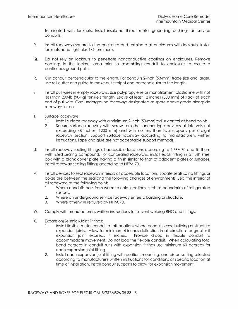
Intermountain Healthcare Dialysis Home Care RemodelIntermountain Medical Center
RACEWAYS AND BOXES FOR ELECTRICAL SYSTEMS26 05 33 - 8
terminated with locknuts. Install insulated throat metal grounding bushings on service conduits.
P. Install raceways square to the enclosure and terminate at enclosures with locknuts. Install locknuts hand tight plus 1/4 turn more.
Q. Do not rely on locknuts to penetrate nonconductive coatings on enclosures. Remove coatings in the locknut area prior to assembling conduit to enclosure to assure a continuous ground path.
R. Cut conduit perpendicular to the length. For conduits 2-inch (53-mm) trade size and larger, use roll cutter or a guide to make cut straight and perpendicular to the length.
S. Install pull wires in empty raceways. Use polypropylene or monofilament plastic line with not less than 200-lb (90-kg) tensile strength. Leave at least 12 inches (300 mm) of slack at each end of pull wire. Cap underground raceways designated as spare above grade alongside raceways in use.
T. Surface Raceways:1. Install surface raceway with a minimum 2-inch (50-mm)radius control at bend points.2. Secure surface raceway with screws or other anchor-type devices at intervals not
exceeding 48 inches (1200 mm) and with no less than two supports per straight raceway section. Support surface raceway according to manufacturer's written instructions. Tape and glue are not acceptable support methods.
U. Install raceway sealing fittings at accessible locations according to NFPA 70 and fill them with listed sealing compound. For concealed raceways, install each fitting in a flush steel box with a blank cover plate having a finish similar to that of adjacent plates or surfaces. Install raceway sealing fittings according to NFPA 70.
V. Install devices to seal raceway interiors at accessible locations. Locate seals so no fittings or boxes are between the seal and the following changes of environments. Seal the interior of all raceways at the following points:1. Where conduits pass from warm to cold locations, such as boundaries of refrigerated
spaces.2. Where an underground service raceway enters a building or structure.3. Where otherwise required by NFPA 70.
W. Comply with manufacturer's written instructions for solvent welding RNC and fittings.
X. Expansion(Seismic)-Joint Fittings:1. Install flexible metal conduit at all locations where conduits cross building or structure
expansion joints. Allow for minimum 4 inches deflection in all directions or greater if expansion joint exceeds 4 inches. Provide droop in flexible conduit to accommodate movement. Do not loop the flexible conduit. When calculating total bend degrees in conduit runs with expansion fittings use minimum 60 degrees for each expansion-joint fitting
2. Install each expansion-joint fitting with position, mounting, and piston setting selected according to manufacturer's written instructions for conditions at specific location at time of installation. Install conduit supports to allow for expansion movement.

Intermountain Healthcare Dialysis Home Care RemodelIntermountain Medical Center
RACEWAYS AND BOXES FOR ELECTRICAL SYSTEMS26 05 33 - 9
Y. Flexible Conduit Connections: Comply with NEMA RV 3. Use a maximum of 72 inches (1830 mm) of flexible conduit for recessed and semi-recessed luminaires, equipment subject to vibration, noise transmission, or movement; and for transformers and motors.1. Use LFMC in damp or wet locations.
Z. Mount boxes at heights indicated on Drawings. If mounting heights of boxes are not individually indicated, give priority to ADA requirements. Install boxes with height measured to center of box unless otherwise indicated.
AA. Recessed Boxes in Masonry Walls: Saw-cut opening for box in center of cell of masonry block, and install box flush with surface of wall. Prepare block surfaces to provide a flat surface for a raintight connection between box and cover plate or supported equipment and box.
BB. Horizontally separate boxes mounted on opposite sides of walls so they are not in the same vertical channel.
CC. Locate boxes so that cover or plate will not span different building finishes.
DD. Support boxes of three gangs or more from more than one side by spanning two framing members or mounting on brackets specifically designed for the purpose.
EE. Fasten junction and pull boxes to or support from building structure. Do not support boxes by conduits.
FF. Set metal floor boxes level and flush with finished floor surface.
GG. Set nonmetallic floor boxes level. Trim after installation to fit flush with finished floor surface.
3.3 SLEEVE AND SLEEVE-SEAL INSTALLATION FOR ELECTRICAL PENETRATIONS
A. Install sleeves and sleeve seals at penetrations of exterior floor and wall assemblies. Comply with requirements in Section 26 05 44 "Sleeves and Sleeve Seals for Electrical Raceways and Cabling."
3.4 FIRESTOPPING AND SOUND TRANSMISSION MITIGATION
A. Install firestopping at penetrations of fire-rated floor and wall assemblies. Comply with requirements in Section 07 84 13 "Penetration Firestopping."
B. Install putty pads with acoustical and firestopping capabilities on all boxes that are installed in wall or partition cavities and in gypsum board ceilings.
3.5 PROTECTION
A. Protect coatings, finishes, and cabinets from damage and deterioration.1. Repair damage to galvanized finishes with zinc-rich paint recommended by
manufacturer.

Intermountain Healthcare Dialysis Home Care RemodelIntermountain Medical Center
RACEWAYS AND BOXES FOR ELECTRICAL SYSTEMS26 05 33 - 10
2. Repair damage to PVC coatings or paint finishes with matching touchup coating recommended by manufacturer.
END OF SECTION

Intermountain Healthcare Dialysis Home Care RemodelIntermountain Medical Center
SLEEVES AND SLEEVE SEALS FOR ELECTRICAL RACEWAYS AND CABLING 26 05 44 - 1
SECTION 26 05 44 - SLEEVES AND SLEEVE SEALS FOR ELECTRICAL RACEWAYS AND CABLING
PART 1 - GENERAL
1.1 RELATED DOCUMENTS
A. Drawings and general provisions of the Contract, including General and Supplementary Conditions and Division 01 Specification Sections, apply to this Section.
1.2 SUMMARY
A. Section Includes:1. Sleeves for raceway and cable penetration of non-fire-rated construction walls
and floors.2. Sleeve-seal systems.3. Sleeve-seal fittings.4. Grout.5. Silicone sealants.
B. Related Requirements:1. Section 07 84 13 "Penetration Firestopping" for penetration firestopping installed in
fire-resistance-rated walls, horizontal assemblies, and smoke barriers, with and without penetrating items.
1.3 ACTION SUBMITTALS
A. Product Data: For each type of product.
B. LEED Submittals:1. Product Data for Credit EQ 4.1: For sealants, documentation including printed
statement of VOC content.2. Laboratory Test Reports for Credit EQ 4: For sealants, documentation indicating
that products comply with the testing and product requirements of the California Department of Health Services' "Standard Practice for the Testing of Volatile Organic Emissions from Various Sources Using Small-Scale Environmental Chambers."
PART 2 - PRODUCTS
2.1 SLEEVES
A. Wall Sleeves:1. Steel Pipe Sleeves: ASTM A 53/A 53M, Type E, Grade B, Schedule 40, zinc coated,
plain ends.2. Cast-Iron Pipe Sleeves: Cast or fabricated "wall pipe," equivalent to ductile-iron
pressure pipe, with plain ends and integral waterstop unless otherwise indicated.

Intermountain Healthcare Dialysis Home Care RemodelIntermountain Medical Center
SLEEVES AND SLEEVE SEALS FOR ELECTRICAL RACEWAYS AND CABLING 26 05 44 - 2
B. Sleeves for Conduits Penetrating Non-Fire-Rated Gypsum Board Assemblies: Galvanized-steel sheet; 0.0239-inch (0.6-mm) minimum thickness; round tube closed with welded longitudinal joint, with tabs for screw-fastening the sleeve to the board.
C. PVC-Pipe Sleeves: ASTM D 1785, Schedule 40.
D. Molded-PVC Sleeves: With nailing flange for attaching to wooden forms.
E. Molded-PE or -PP Sleeves: Removable, tapered-cup shaped, and smooth outer surface with nailing flange for attaching to wooden forms.
F. Sleeves for Rectangular Openings:1. Material: Galvanized sheet steel.2. Minimum Metal Thickness:
a. For sleeve cross-section rectangle perimeter less than 50 inches (1270 mm) and with no side larger than 16 inches (400 mm), thickness shall be 0.052 inch (1.3 mm).
b. For sleeve cross-section rectangle perimeter 50 inches (1270 mm) or more and one or more sides larger than 16 inches (400 mm), thickness shall be 0.138 inch (3.5 mm).
2.2 SLEEVE-SEAL SYSTEMS
A. Description: Modular sealing device, designed for field assembly, to fill annular space between sleeve and raceway or cable.1. Sealing Elements: EPDM rubber interlocking links shaped to fit surface of pipe.
Include type and number required for pipe material and size of pipe.2. Pressure Plates: Stainless steel.3. Connecting Bolts and Nuts: Stainless steel of length required to secure pressure
plates to sealing elements.
2.3 SLEEVE-SEAL FITTINGS
A. Description: Manufactured plastic, sleeve-type, waterstop assembly made for embedding in concrete slab or wall. Unit shall have plastic or rubber waterstop collar with center opening to match piping OD.
2.4 GROUT
A. Description: Nonshrink; recommended for interior and exterior sealing openings in non-fire-rated walls or floors.
B. Standard: ASTM C 1107/C 1107M, Grade B, post-hardening and volume-adjusting, dry, hydraulic-cement grout.
C. Design Mix: 5000-psi (34.5-MPa), 28-day compressive strength.
D. Packaging: Premixed and factory packaged.

Intermountain Healthcare Dialysis Home Care RemodelIntermountain Medical Center
SLEEVES AND SLEEVE SEALS FOR ELECTRICAL RACEWAYS AND CABLING 26 05 44 - 3
2.5 SILICONE SEALANTS
A. Silicone Sealants: Single-component, silicone-based, neutral-curing elastomeric sealants of grade indicated below.1. Grade: Pourable (self-leveling) formulation for openings in floors and other
horizontal surfaces that are not fire rated.2. Sealant shall have VOC content of 50 g/L or less when calculated according to
40 CFR 59, Subpart D (EPA Method 24).3. Sealant shall comply with the testing and product requirements of the California
Department of Health Services' "Standard Practice for the Testing of Volatile Organic Emissions from Various Sources Using Small-Scale Environmental Chambers."
B. Silicone Foams: Multicomponent, silicone-based liquid elastomers that, when mixed, expand and cure in place to produce a flexible, nonshrinking foam.
PART 3 - EXECUTION
3.1 SLEEVE INSTALLATION FOR NON-FIRE-RATED ELECTRICAL PENETRATIONS
A. Comply with NECA 1.
B. Comply with NEMA VE 2 for cable tray and cable penetrations.
C. Sleeves for Conduits Penetrating Above-Grade Non-Fire-Rated Concrete and Masonry-Unit Floors and Walls:1. Interior Penetrations of Non-Fire-Rated Walls and Floors:
a. Seal annular space between sleeve and raceway or cable, using joint sealant appropriate for size, depth, and location of joint. Comply with requirements in Section 07 92 00 "Joint Sealants."
b. Seal space outside of sleeves with mortar or grout. Pack sealing material solidly between sleeve and wall so no voids remain. Tool exposed surfaces smooth; protect material while curing.
2. Use pipe sleeves unless penetration arrangement requires rectangular sleeved opening.
3. Size pipe sleeves to provide 1/4-inch (6.4-mm) annular clear space between sleeve and raceway or cable unless sleeve seal is to be installed or unless seismic criteria require different clearance.
4. Install sleeves for wall penetrations unless core-drilled holes or formed openings are used. Install sleeves during erection of walls. Cut sleeves to length for mounting flush with both surfaces of walls. Deburr after cutting.
5. Install sleeves for floor penetrations. Extend sleeves installed in floors 4 inches above finished floor level. Install sleeves during erection of floors.
D. Sleeves for Conduits Penetrating Non-Fire-Rated Gypsum Board Assemblies:1. Use circular metal sleeves unless penetration arrangement requires rectangular
sleeved opening.2. Seal space outside of sleeves with approved joint compound for gypsum board
assemblies.

Intermountain Healthcare Dialysis Home Care RemodelIntermountain Medical Center
SLEEVES AND SLEEVE SEALS FOR ELECTRICAL RACEWAYS AND CABLING 26 05 44 - 4
E. Roof-Penetration Sleeves: Seal penetration of individual raceways and cables with flexible boot-type flashing units applied in coordination with roofing work.
F. Aboveground, Exterior-Wall Penetrations: Seal penetrations using cast-iron pipe sleeves and mechanical sleeve seals. Select sleeve size to allow for 1-inch (25-mm) annular clear space between pipe and sleeve for installing mechanical sleeve seals.
G. Underground, Exterior-Wall and Floor Penetrations: Install cast-iron pipe sleeves. Size sleeves to allow for 1-inch (25-mm) annular clear space between raceway or cable and sleeve for installing sleeve-seal system.
3.2 SLEEVE-SEAL-SYSTEM INSTALLATION
A. Install sleeve-seal systems in sleeves in exterior concrete walls and slabs-on-grade at raceway entries into building.
B. Install type and number of sealing elements recommended by manufacturer for raceway or cable material and size. Position raceway or cable in center of sleeve. Assemble mechanical sleeve seals and install in annular space between raceway or cable and sleeve. Tighten bolts against pressure plates that cause sealing elements to expand and make watertight seal.
3.3 SLEEVE-SEAL-FITTING INSTALLATION
A. Install sleeve-seal fittings in new walls and slabs as they are constructed.
B. Assemble fitting components of length to be flush with both surfaces of concrete slabs and walls. Position waterstop flange to be centered in concrete slab or wall.
C. Secure nailing flanges to concrete forms.
D. Using grout, seal the space around outside of sleeve-seal fittings.
END OF SECTION

Intermountain Healthcare Dialysis Home Care RemodelIntermountain Medical Center
IDENTIFICATION FOR ELECTRICAL SYSTMES 26 05 53 - 1
SECTION 26 05 53 - IDENTIFICATION FOR ELECTRICAL SYSTEMS
PART 1 - GENERAL
1.1 RELATED DOCUMENTS
A. Drawings and general provisions of the Contract, including General and Supplementary Conditions and Division 01 Specification Sections, apply to this Section.
1.2 SUMMARY
A. Section Includes:1. Identification for raceways.2. Identification of power and control cables.3. Identification for conductors.4. Underground-line warning tape.5. Warning labels and signs.6. Instruction signs.7. Equipment identification labels, including arc-flash warning labels.8. Miscellaneous identification products.
1.3 ACTION SUBMITTALS
A. Product Data: For each type of product.1. Include construction details, material descriptions, dimensions of individual components
and profiles, and finishes for electrical identification products.
B. Samples: For each type of label and sign to illustrate composition, size, colors, lettering style, mounting provisions, and graphic features of identification products.
C. Identification Schedule: For each piece of electrical equipment and electrical system components to be an index of nomenclature for electrical equipment and system components used in identification signs and labels. Use same designations indicated on Drawings.
D. Delegated-Design Submittal: For arc-flash hazard study.
PART 2 - PRODUCTS
2.1 PERFORMANCE REQUIREMENTS
A. Comply with ASME A13.1 and IEEE C2.
B. Comply with NFPA 70.
C. Comply with 29 CFR 1910.144 and 29 CFR 1910.145.

Intermountain Healthcare Dialysis Home Care RemodelIntermountain Medical Center
IDENTIFICATION FOR ELECTRICAL SYSTMES 26 05 53 - 2
D. Comply with ANSI Z535.4 for safety signs and labels.
E. Adhesive-attached labeling materials, including label stocks, laminating adhesives, and inks used by label printers, shall comply with UL 969.
F. Thermal Movements: Allow for thermal movements from ambient and surface temperature changes.1. Temperature Change: 120 deg F (67 deg C), ambient; 180 deg F (100 deg C), material
surfaces.
2.2 COLOR AND LEGEND REQUIREMENTS
A. Use the following color code for all electrical equipment that is specified to be labeled:1. Standby Power Circuits: Black letters on red field.2. Life Safety Branch Circuits: White letters on orange Field3. Critical Branch Circuits: White letters on red Field4. Equipment System Circuits: White letters on green field.5. Normal Power Circuits: White letters on black field.6. Uninterruptible Power Supply (UPS): White letters on gray field. 7. Fire Alarm: Red letters on white field.8. Communications: White letters on blue field.
B. Warning labels and signs shall include, but are not limited to, the following legends:1. Multiple Power Source Warning: "DANGER - ELECTRICAL SHOCK HAZARD - EQUIPMENT HAS
MULTIPLE POWER SOURCES."2. Workspace Clearance Warning: "WARNING - OSHA REGULATION - AREA IN FRONT OF
ELECTRICAL EQUIPMENT MUST BE KEPT CLEAR FOR XX INCHES" where XX is replaced by the clearance requirements of NFPA 70.
C. Raceways:1. Labeling: Black on orange. Include system voltage and type.2. Color Coding for Raceways:
a. Fire Alarm: Red
2.3 LABELS
A. Vinyl Labels for Raceways Carrying Circuits at 600 V or Less: printed, flexible labels laminated with a clear, weather- and chemical-resistant coating and matching wraparound clear adhesive tape for securing label ends.
B. Indoor Equipment Labels: Self-adhesive, engraved, laminated acrylic or melamine plastic label. Unless otherwise indicated, provide a single line of text with 1/2-inch- (13-mm-) high letters on 1-1/2-inch- (38-mm-) high label; where two lines of text are required, use labels 2 inches (50 mm) high. Color coded as indicated in Color and Legend Requirements.
C. Outdoor Equipment: Engraved, laminated acrylic or melamine plastic label, punched or drilled for mechanical fasteners. Unless otherwise indicated, provide a single line of text with 1/2-inch- (13-mm-) high letters on 1-1/2-inch- (38-mm-) high label; where two lines of text are required, use labels 2 inches (50 mm) high. Color coded as indicated in Color and Legend Requirements.

Intermountain Healthcare Dialysis Home Care RemodelIntermountain Medical Center
IDENTIFICATION FOR ELECTRICAL SYSTMES 26 05 53 - 3
2.4 BANDS AND TUBES:
A. Snap-Around, Color-Coding Bands for Cables: Slit, pretensioned, flexible, solid-colored acrylic sleeves, 2 inches (50 mm) long, with diameters sized to suit diameters of raceways or cables they identify, and that stay in place by gripping action.
2.5 TAPES AND STENCILS:
A. Marker Tapes: Vinyl or vinyl-cloth, self-adhesive wraparound type, with circuit identification legend machine printed by thermal transfer or equivalent process.
2.6 Signs
A. Laminated Acrylic or Melamine Plastic Signs:1. Engraved legend.2. Thickness:
a. For signs up to 20 sq. inches (129 sq. cm), minimum 1/16-inch- (1.6-mm-).b. For signs larger than 20 sq. inches (129 sq. cm), 1/8 inch (3.2 mm) thick.c. Engraved legend with white letters on a dark grey background.d. Punched or drilled for mechanical fasteners.e. Framed with mitered acrylic molding and arranged for attachment at applicable
equipment.
2.7 MISCELLANEOUS IDENTIFICATION PRODUCTS
A. Paint: Comply with requirements in painting Sections for paint materials and application requirements. Retain paint system applicable for surface material and location (exterior or interior).
B. Fasteners for Labels and Signs: Self-tapping, stainless-steel screws or stainless-steel machine screws with nuts and flat and lock washers.
PART 3 - EXECUTION
3.1 PREPARATION
A. Self-Adhesive Identification Products: Before applying electrical identification products, clean substrates of substances that could impair bond, using materials and methods recommended by manufacturer of identification product.
3.2 INSTALLATION
A. Verify and coordinate identification names, abbreviations, colors, and other features with requirements in other Sections requiring identification applications, Drawings, Shop Drawings, manufacturer's wiring diagrams, and operation and maintenance manual. Use consistent designations throughout Project.

Intermountain Healthcare Dialysis Home Care RemodelIntermountain Medical Center
IDENTIFICATION FOR ELECTRICAL SYSTMES 26 05 53 - 4
B. Install identifying devices before installing acoustical ceilings and similar concealment.
C. Verify identity of each item before installing identification products.
D. Install identification materials and devices at locations for most convenient viewing without interference with operation and maintenance of equipment. Install access doors or panels to provide view of identifying devices.
E. Apply identification devices to surfaces that require finish after completing finish work.
F. Attach signs and plastic labels that are not self-adhesive type with mechanical fasteners appropriate to the location and substrate.
G. Attach plastic raceway and cable labels that are not self-adhesive type with clear vinyl tape, with adhesive appropriate to the location and substrate.
H. System Identification for Feeder Raceways: Each color-coding band shall completely encircle cable or conduit. Place adjacent bands of two-color markings in contact, side by side. Locate bands at changes in direction, at penetrations of walls and floors, at 50-foot (15-m) maximum intervals in straight runs, and at 25-foot (7.6-m) maximum intervals in congested areas.
I. During backfilling of trenches, install continuous underground-line warning tape directly above cable or raceway at 6 to 8 inches (150 to 200 mm) below finished grade. Use multiple tapes where width of multiple lines installed in a common trench [or concrete envelope ]exceeds 16 inches (400 mm) overall.
3.3 IDENTIFICATION SCHEDULE
A. Accessible Raceways, including above accessible ceilings, for all Feeder Circuits and for Branch Circuit rated more than 30A: Identify with self-adhesive vinyl label. Install labels at 30-foot (10-m) maximum intervals.
B. Accessible Raceways and Cables, including above accessible ceilings, within Buildings: Identify the covers of each junction and pull box of the following systems with self-adhesive vinyl labels containing the wiring system legend and system voltage. System legends shall be as follows:1. Standby Power2. Life Safety Branch3. Critical Branch4. Equipment System5. Normal Power6. UPS7. Fire Alarm8. Communications9. Access Control
C. Power-Circuit Conductor Identification, 600 V or Less: For conductors in vaults, pull and junction boxes, manholes, and handholes, use color-coding conductor tape to identify the phase.1. Grounded Systems: Color-Coding for Phase- , Neutral- and Voltage-Level Identification: Use
colors listed below for feeder and branch-circuit conductors.

Intermountain Healthcare Dialysis Home Care RemodelIntermountain Medical Center
IDENTIFICATION FOR ELECTRICAL SYSTMES 26 05 53 - 5
a. Colors for 208/120-V Circuits:1) Phase A: Black.2) Phase B: Red.3) Phase C: Blue.4) Feeder Neutral: White5) Branch Circuit Neutral: White with colored stripe matching the color of the
phase circuit that is paired with the neutral.b. Colors for 480/277-V Circuits:
1) Phase A: Brown.2) Phase B: Orange.3) Phase C: Yellow.4) Feeder Neutral: Grey5) Branch Circuit Neutral: Grey with colored stripe matching the color of the
phase circuit that is paired with the neutral.2. Isolated Power Systems: Color-Coding for Circuit Identification: Use colors listed below for
Isolated Power conductors.a. Isolated Conductor No.1: Orange with at least one distinctive colored stripe other
than white, green, or grey along the entire length of the conductor.b. Isolated Conductor No. 2: Brown with at least one distinctive colored stripe other
than white, green, or grey along the entire length of the conductor.3. Color shall be factory applied or field applied for sizes larger than No. 8 AWG if authorities
having jurisdiction permit.a. Field-Applied, Color-Coding Conductor Tape: Apply in half-lapped turns for a
minimum distance of 6 inches (150 mm) from terminal points and in boxes where splices or taps are made. Apply last two turns of tape with no tension to prevent possible unwinding. Locate bands to avoid obscuring factory cable markings.
4. Provide a sign at each panelboard identifying the color coding scheme.
D. Install instructional sign, including the color code for grounded and ungrounded conductors using adhesive-film-type labels.
E. Control-Circuit Conductor Identification: For conductors and cables in pull and junction boxes, manholes, and handholes, use self-adhesive vinyl labels with the conductor or cable designation, origin, and destination.
F. Control-Circuit Conductor Termination Identification: For identification at terminations, provide self-adhesive vinyl labels with the conductor designation.
G. Conductors To Be Extended in the Future: Attach write-on tags to conductors and list source.
H. Auxiliary Electrical Systems Conductor Identification: Identify field-installed alarm, control, and signal connections.1. Identify conductors, cables, and terminals in enclosures and at junctions, terminals, and pull
points. Identify by system and circuit designation.2. Use system of marker-tape designations that is uniform and consistent with system used by
manufacturer for factory-installed connections.3. Coordinate identification with Project Drawings, manufacturer's wiring diagrams, and
operation and maintenance manual.

Intermountain Healthcare Dialysis Home Care RemodelIntermountain Medical Center
IDENTIFICATION FOR ELECTRICAL SYSTMES 26 05 53 - 6
I. Locations of Underground Lines: Identify with underground-line warning tape for power, lighting, communication, and control wiring and optical-fiber cable.1. Limit use of underground-line warning tape to direct-buried cables.2. Install underground-line warning tape for direct-buried cables and cables in raceways.
J. Workspace Indication: Install floor marking tape to show working clearances in the direction of access to live parts. Workspace shall comply with NFPA 70 and 29 CFR 1926.403 unless otherwise indicated. Do not install at flush-mounted panelboards and similar equipment in finished spaces.
K. Warning Labels for Indoor Cabinets, Boxes, and Enclosures for Power and Lighting: Self-adhesive warning labels.1. Comply with 29 CFR 1910.145.2. Identify system voltage with black letters on an orange background.3. Apply to exterior of door, cover, or other access.4. For equipment with multiple power or control sources, apply to door or cover of equipment,
including, but not limited to, the following:a. Power-transfer switches.b. Controls with external control power connections.
L. Arc Flash Warning Labeling: Self-adhesive thermal transfer vinyl labels.1. Comply with NFPA 70E and ANSI Z535.4.2. Comply with Section 26 05 74 "Overcurrent Protective Device Arc-Flash Study" requirements
for arc-flash warning labels.
M. Operating Instruction Signs: Install instruction signs to facilitate proper operation and maintenance of electrical systems and items to which they connect. Install instruction signs with approved legend where instructions are needed for system or equipment operation.
N. Emergency Operating Instruction Signs: Install instruction signs with white legend on a red background with minimum 3/8-inch- (10-mm-) high letters for emergency instructions at equipment used for power transfer or load shedding.
O. Equipment Identification Labels: On each unit of equipment, install unique designation label that is consistent with wiring diagrams, schedules, and operation and maintenance manual. Apply labels to disconnect switches and protection equipment, central or master units, control panels, control stations, terminal cabinets, and racks of each system. Systems include power, lighting, control, communication, signal, monitoring, and alarm unless equipment is provided with its own identification.1. Labeling Instructions:
a. Elevated Components: Increase sizes of labels and letters to those appropriate for viewing from the floor.
b. Fasten mechanically fastened labels with appropriate mechanical fasteners that do not change the NEMA or NRTL rating of the enclosure.
2. Equipment To Be Labeled:a. Panelboards: Typewritten directory of circuits in the location provided by panelboard
manufacturer. b. Enclosures and electrical cabinets.c. Lighting control relay cabinets.d. Access doors and panels for concealed electrical items.

Intermountain Healthcare Dialysis Home Care RemodelIntermountain Medical Center
IDENTIFICATION FOR ELECTRICAL SYSTMES 26 05 53 - 7
e. Switchgear.f. Switchboards.g. Transformers: Label that includes tag designation shown on Drawings for the
transformer, feeder, and panelboards or equipment supplied by the secondary.h. Emergency system boxes and enclosures.i. Motor-control centers.j. Enclosed switches.k. Enclosed circuit breakers.l. Enclosed controllers.m. Variable-speed controllers.n. Push-button stations.o. Power-transfer equipment.p. Contactors.q. Remote-controlled switches, dimmer modules, and control devices.r. Battery-inverter units.s. Battery racks.t. Power-generating units.u. Monitoring and control equipment.v. UPS equipment.w. Communications Equipment Racks.x. Fire Alarm System.y. Access Control System.z. Overhead Paging System.aa. Nurse Call System.
END OF SECTION

Intermountain Healthcare Dialysis Home Care RemodelIntermountain Medical Center
LIGHTING CONTROL DEVICES 26 09 23 - 1
SECTION 26 09 23 LIGHTING CONTROL DEVICES
PART 1 - GENERAL
1.1 RELATED DOCUMENTS
A. Drawings and general provisions of the Contract, including General and Supplementary Conditions and Division 01 Specification Sections, apply to this Section.
1.2 SUMMARY
A. Section Includes:1. Photoelectric switches.2. Standalone daylight-harvesting switching controls.3. Daylight-harvesting dimming controls.4. Room Controllers.5. Stand Alone Indoor occupancy sensors.6. Lighting contactors.7. Emergency shunt relays.8. Low-Voltage Controllers
B. Related Requirements:1. Section 26 27 26 "Wiring Devices" for wall-box dimmers, wall-switch occupancy sensors,
and manual light switches.
1.3 ACTION SUBMITTALS
A. Product Data: For each type of product.
B. Shop Drawings: Show installation details for occupancy and light-level sensors.1. Submit complete scale drawing showing recommended location for each sensor, optimized
fro project conditions and coverage patterns for submitted devices.2. Interconnection diagrams showing field-installed wiring.3. Include diagrams for power, signal, and control wiring.
1.4 INFORMATIONAL SUBMITTALS
A. Field quality-control reports.
1.5 CLOSEOUT SUBMITTALS
A. Operation and Maintenance Data: For each type of lighting control device to include in emergency, operation, and maintenance manuals.

Intermountain Healthcare Dialysis Home Care RemodelIntermountain Medical Center
LIGHTING CONTROL DEVICES 26 09 23 - 2
PART 2 - PRODUCTS
2.1 OUTDOOR PHOTOELECTRIC SWITCHES
A. Manufacturers: Subject to compliance with requirements, provide products by one of the following:1. Cooper Industries, Inc.2. Intermatic, Inc.3. Leviton Manufacturing Co., Inc.4. NSi Industries LLC.5. TE Connectivity Ltd.
B. Description: Solid state, with SPST dry contacts rated for 1800 VA, to operate connected load, complying with UL 773.1. Listed and labeled as defined in NFPA 70, by a qualified testing agency, and marked for
intended location and application.2. Light-Level Monitoring Range: 1.5 to 10 fc (16.14 to 108 lux), with an adjustment for turn-on
and turn-off levels within that range.3. Time Delay: Thirty-second minimum, to prevent false operation.4. Lightning Arrester: Air-gap type.5. Mounting: Twist lock complying with NEMA C136.10, with base.
2.2 DAYLIGHT-HARVESTING SWITCHING CONTROLS
A. Provide products that are of the same manufacturer or compatible with the manufacturers listed in Section 26 09 43, Relay Based Lighting Controls.
B. Manufacturers: Subject to compliance with requirements, provide products by one of the following:1. Eaton (Cooper Controls), Inc.2. Lutron, Inc.3. Leviton Manufacturing Co., Inc.4. Philips Controls5. Acuity Controls6. Nextlite7. ETC8. Douglas Controls9. WattStopper
C. Ceiling-Mounted Switching Controls: Solid-state, light-level sensor unit, with separate power pack, to detect changes in indoor lighting levels that are perceived by the eye.
D. Electrical Components, Devices, and Accessories:1. Listed and labeled as defined in NFPA 70, by a qualified testing agency, and marked for
intended location and application.2. Operating Ambient Conditions: Dry interior conditions, 32 to 120 deg F (0 to 49 deg C).3. Sensor Output: Contacts rated to operate the associated power pack, complying with
UL 773A. Sensor is powered by the power pack.4. Power Pack: Dry contacts rated for 20-A ballast load at 120- and 277-V ac. Sensor has 24-
V dc, 150-mA, Class 2 power source, as defined by NFPA 70.5. General Space Sensors Light-Level Monitoring Range: 10 to 200 fc (108 to 2152 lux), with
an adjustment for turn-on and turn-off levels within that range.

Intermountain Healthcare Dialysis Home Care RemodelIntermountain Medical Center
LIGHTING CONTROL DEVICES 26 09 23 - 3
6. Atrium Space Sensors Light-Level Monitoring Range: 100 to 1000 fc (1080 to 10 800 lux), with an adjustment for turn-on and turn-off levels within that range.
7. Skylight Sensors Light-Level Monitoring Range: 1000 to 10,000 fc (10 800 to 108 000 lux), with an adjustment for turn-on and turn-off levels within that range.
8. Time Delay: Adjustable from 5 to 300 seconds to prevent cycling.9. Set-Point Adjustment: Equip with deadband adjustment of 25, 50, and 75 percent above the
"on" set point, or provide with separate adjustable "on" and "off" set points.10. Test Mode: User selectable, overriding programmed time delay to allow settings check.11. Control Load Status: User selectable to confirm that load wiring is correct.12. Indicator: Two digital displays to indicate the beginning of on-off cycles.
2.3 DAYLIGHT-HARVESTING DIMMING CONTROLS
A. Provide products that are of the same manufacturer or compatible with the manufacturers listed in Section 26 09 43, Relay Based Lighting Controls.
B. Manufacturers: Subject to compliance with requirements, provide products by one of the following:1. Eaton (Cooper Controls), Inc.2. Lutron, Inc.3. Leviton Manufacturing Co., Inc.4. Philips Controls5. Acuity Controls6. NextLite7. Douglas Controls8. ETC9. WattStopper
C. System Description: Sensing daylight and electrical lighting levels, the system adjusts the indoor electrical lighting levels. As daylight increases, the lights are dimmed.1. Lighting control set point is based on two lighting conditions:
a. When no daylight is present (target level).b. When significant daylight is present.
2. System programming is done with two hand-held, remote-control tools.a. Initial setup tool.b. Tool for occupants to adjust the target levels by increasing the set point up to 25
percent, or by minimizing the electric lighting level.
D. Ceiling-Mounted Dimming Controls: Solid-state, light-level sensor unit, with separate controller unit, to detect changes in lighting levels that are perceived by the eye. The separate dimming control may be located in the appropriate relay cabint for these circuits. 1. Listed and labeled as defined in NFPA 70, by a qualified testing agency, and marked for
intended location and application.2. Sensor Output: 0- to 10-V dc to operate electronic dimming ballasts. Sensor is powered by
controller unit.3. Power Pack: Sensor has 24-V dc, Class 2 power source, as defined by NFPA 70.4. Light-Level Sensor Set-Point Adjustment Range: 20 to 100 fc (120 to 600 lux).
2.4 ROOM CONTROLLERS
A. Room Controllers are used to independently control lighting and switched receptacles.

Intermountain Healthcare Dialysis Home Care RemodelIntermountain Medical Center
LIGHTING CONTROL DEVICES 26 09 23 - 4
B. Provide products that are compatible with Indoor Occupancy Sensors.
C. Digitally addressable room controller with the following functions.1. Autonomous space control.2. Networking to a central Dialog control system.3. Networking to a central BACnet based management system.
D. The Room Controller shall consist of:1. A universal voltage type (120Vac/277Vac/347Vac) power supply.2. Four 20A rated relays complete with manual override. Circuit Load rating dependent on
usage. One circuit dedicated for 20A receptacle control. 3. Four 0-10V control channels, capable of 100mA current sinking4. A port to connect downstream switches, occupancy sensors and daylight sensors. 5. A port to connect upstream to BACnet IP building management system. The Controller shall
communicate using native BACnet command objects appropriate for the application.6. An indicating LED to aid in locating the controller in a darkened ceiling space.7. Circuit testing buttons8. Capable of connecting with WUL-39249. Output 24Vac 120mA10. Relay Ratings
a. 20A Suitable for General Purpose Loads @ 120/277 VACb. 20A Suitable for Standard Ballasts and Tungsten Loads @ 120/277 VACc. 16A Suitable for Electronic Ballasts @ 120/277 VACd. 0.5HP @120/277 VAC.
11. The Room Controller relays shall be connected such that 120Vac plug load(s) and 277Vac lighting loads can be switched by a single Controller with no additional add-ons or remote modules
12. The Room Controller shall mount to electrical junction box via threaded ½” chase nipple. No other mounting hardware shall be required.
13. Switches shall connect to the lighting control network via a common low voltage, 2-wire, non-polarized data line.a. Switches shall be factory configured and programmed to control one or more outputs
in the lighting control system.b. Switches can be programmed for preset control to set a specific lighting scene.c. Switches, with LED indicators to indicate both ON and OFF output/group status, shall
be available with 2 or 4 single button switches per gang. Switch to fit standard Decora opening.
d. Switches and switch hardware shall mount to standard wall boxes.e. Each switch shall provide a location for a label to identify function. The label shall be
under a clear plastic cover and shall be field replaceable should the operation of the switch change. Permanently etched switches are not acceptable.
14. Dimmer switches shall be connected to the lighting control network via a common low voltage 2-wire, non-polarized data line.a. Dimmer switches shall be capable of raising or lowering light levels of individual or
groups of lighting fixtures.15. Space Control Requirements:
a. Provide manual-on / auto-off control for lighting in all spaces that are controlled by a Room Controller.
b. Provide auto-on / auto-off control for all switched receptacles that are controlled by a Room Controller.
c. Provide auto-on / auto-off control for HVAC serving all spaces that contain a Room Controller. Control to be provided by either two-wire signal based on relay contact position or direct communication with the building management system using BACnet commands. Coordinate with building management system installer.

Intermountain Healthcare Dialysis Home Care RemodelIntermountain Medical Center
LIGHTING CONTROL DEVICES 26 09 23 - 5
2.5 INDOOR OCCUPANCY SENSORS
A. Provide products that are of the same manufacturer or compatible with the manufacturers listed in Section 26 09 43, Relay Based Lighting Controls.
B. General Requirements for Sensors: Wall- or ceiling-mounted, solid-state indoor occupancy sensors with a separate power pack.1. Listed and labeled as defined in NFPA 70, by a qualified testing agency, and marked for
intended location and application.2. Operation: Unless otherwise indicated, turn lights on when coverage area is occupied, and
turn them off when unoccupied; with a time delay for turning lights off, adjustable over a minimum range of 1 to 15 minutes.
3. In locations where the sensor or the local switch is/are marked “VS” the sensor shall turn the lights off automatically upon room vacancy. The lights shall turn on only upon activation from the associated wall station.
4. Sensor Output: Contacts rated to operate the connected relay, complying with UL 773A. Sensor is powered from the power pack.
5. Power Pack: Dry contacts rated for 20-A ballast load at 120- and 277-V ac, for 13-A tungsten at 120-V ac, and for 1 hp at 120-V ac Sensor has 24-V dc, 150-mA, Class 2 power source, as defined by NFPA 70.
6. Mounting:a. Sensor: Suitable for mounting in any position on a standard outlet box.b. Relay: Externally mounted through a 1/2-inch (13-mm) knockout in a standard
electrical enclosure.c. Time-Delay and Sensitivity Adjustments: Recessed and concealed behind hinged
door.7. Indicator: Digital display, to show when motion is detected during testing and normal
operation of sensor.8. Bypass Switch: Override the "on" function in case of sensor failure.9. Automatic Light-Level Sensor: Adjustable from 2 to 200 fc (21.5 to 2152 lux); turn lights off
when selected lighting level is present.
C. Dual-Technology Type: Ceiling mounted; detect occupants in coverage area using both PIR and ultrasonic detection methods. The particular technology or combination of technologies that control on-off functions is selectable in the field by operating controls on unit.1. Sensitivity Adjustment: Separate for each sensing technology.2. Detector Sensitivity: Detect occurrences of 6-inch- (150-mm-) minimum movement of any
portion of a human body that presents a target of not less than 36 sq. in. (232 sq. cm), and detect a person of average size and weight moving not less than 12 inches (305 mm) in either a horizontal or a vertical manner at an approximate speed of 12 inches/s (305 mm/s).
3. Detection Coverage (Standard Room): Detect occupancy anywhere within a circular area of 1000 sq. ft. (93 sq. m) when mounted on a 96-inch- (2440-mm-) high ceiling.
4. Remote powerpacks using one or more sensors shall be used to cover space as indicated on drawings.
5. Device shall be vacancy sensing (in conjunction with local wall station) if marked “VS”. Otherwise device shall be occupancy sensing.
2.6 SWITCHBOX-MOUNTED OCCUPANCY SENSORS
A. Provide products that are of the same manufacturer or compatible with the manufacturers listed in Section 26 09 43, Relay Based Lighting Controls.

Intermountain Healthcare Dialysis Home Care RemodelIntermountain Medical Center
LIGHTING CONTROL DEVICES 26 09 23 - 6
B. General Requirements for Sensors: Automatic-wall-switch occupancy sensor, suitable for mounting in a single gang switchbox.1. Listed and labeled as defined in NFPA 70, by a qualified testing agency, and marked for
intended location and application, 2. Operating Ambient Conditions: Dry interior conditions, 32 to 120 deg F (0 to 49 deg C).3. Switch Rating: Not less than 800-VA LED at 120 V, 1200-VA LED loads at 277 V,
C. Wall-Switch Sensor:1. Standard Range: 180-degree field of view, field adjustable from 180 to 40 degrees; with a
minimum coverage area of 900 sq. ft. (84 sq. m).2. Sensing Technology: Dual technology - PIR and ultrasonic.3. Switch Type: SP. SP, manual "on," automatic "off."4. Voltage: Dual voltage, 120 and 277 V; 5. Ambient-Light Override: Concealed, field-adjustable, light-level sensor from 10 to 150 fc
(108 to 1600 lux). The switch prevents the lights from turning on when the light level is higher than the set point of the sensor.
6. Concealed, field-adjustable, "off" time-delay selector at up to 30 minutes.7. Adaptive Technology: Self-adjusting circuitry detects and memorizes usage patterns of the
space and helps eliminate false "off" switching.8. Device shall be Vacancy sensing if marked VS or occupancy sensing if not otherwise
marked.
2.7 LIGHTING CONTACTORS
A. Manufacturers: Subject to compliance with requirements, provide products by one of the following:1. Allen-Bradley/Rockwell Automation.2. ASCO Power Technologies, LP; a division of Emerson Electric Co.3. Eaton Corporation.4. GE Industrial Systems; Total Lighting Control.5. Square D; a brand of Schneider Electric.
B. Description: Electrically operated, electrically held, combination-type lighting contactors with fusible switch complying with NEMA ICS 2 and UL 508.1. Current Rating for Switching: Listing or rating consistent with type of load served, including
tungsten filament, inductive, and high-inrush ballast (ballast with 15 percent or less total harmonic distortion of normal load current).
2. Fault Current Withstand Rating: Equal to or exceeding the available fault current at the point of installation.
3. Enclosure: Comply with NEMA 250.4. Provide with control and pilot devices as indicated on Drawings, matching the NEMA type
specified for the enclosure.
C. Interface with DDC System for HVAC: Provide hardware interface to enable the DDC system for HVAC to monitor and control lighting control systems and contactors.1. Monitoring: On-off status2. Control: On-off operation
2.8 EMERGENCY SHUNT RELAY
A. Manufacturers: Subject to compliance with requirements, provide products by one of the following:1. Eaton (Cooper Controls), Inc.

Intermountain Healthcare Dialysis Home Care RemodelIntermountain Medical Center
LIGHTING CONTROL DEVICES 26 09 23 - 7
2. Lutron, Inc.3. Leviton Manufacturing Co., Inc.4. Philips Controls5. Acuity Controls6. NextLite7. Douglas Controls8. Wattstopper
B. Description: Normally closed, electrically held relay, arranged for wiring in parallel with automatic switching contacts; complying with UL 924.1. Coil Rating: as scheduled.
2.9 LOW-VOLTAGE CONTROLLERS
A. Low-Voltage Controllers are used to turn on and dim line voltage lighting safely when used with Nurse Call Pillow Speakers, Bed Side-Rail Controls and Momentary Dry Contact Switches.
B. Manufacturers: Subject to compliance with requirements, provide the following:1. Curbell Medical Products (Basis of Design is # LVC-2000-001)
C. Description: 3 Channel lighting controller to continuously dim 2 channels using 0-10 vdc signals to the dimming LED drivers for the ambient light and reading light channels in the luminaire and to switch one channel via the LED driver(s) for the exam light portion of the luminaire. Controller shall have control inputs from nurse call pillow speaker contacts and also be switched from wall switches as shown.
D. Installation: Lighting Controller shall be installed above the accessible ceiling outside the patient room for ease of access. All leads shall be extended from the switches, luminaire and nurse call system in an approved manner. Installer shall provide a NEMA 12 enclosure suitable for the purpose and mount the controller in this box. Observe required high and low voltage separation and physical barriers. Label the cover with the words “LIGHTING CONTROLLER FOR ROOM ####”.
2.10 CONDUCTORS AND CABLES
A. Power Wiring to Supply Side of Remote-Control Power Sources: Not smaller than No. 12 AWG. Comply with requirements in Section 26 05 19 "Low-Voltage Electrical Power Conductors and Cables."
B. Classes 2 and 3 Control Cable: Multiconductor cable with stranded-copper conductors not smaller than No. 22 AWG. Comply with requirements in Section 26 05 19 "Low-Voltage Electrical Power Conductors and Cables."
C. Class 1 Control Cable: Multiconductor cable with stranded-copper conductors not smaller than No. 18 AWG. Comply with requirements in Section 26 05 19 "Low-Voltage Electrical Power Conductors and Cables."

Intermountain Healthcare Dialysis Home Care RemodelIntermountain Medical Center
LIGHTING CONTROL DEVICES 26 09 23 - 8
PART 3 - EXECUTION
3.1 SENSOR INSTALLATION
A. Coordinate layout and installation of ceiling-mounted devices with other construction that penetrates ceilings or is supported by them, including light fixtures, HVAC equipment, smoke detectors, fire-suppression systems, and partition assemblies.
B. Install and aim sensors in locations to achieve not less than 90 percent coverage of areas indicated. Do not exceed coverage limits specified in manufacturer's written instructions.
3.2 CONTACTOR INSTALLATION
A. Mount electrically held lighting contactors with elastomeric isolator pads to eliminate structure-borne vibration, unless contactors are installed in an enclosure with factory-installed vibration isolators.
3.3 WIRING INSTALLATION
A. Wiring Method: Comply with Section 26 05 19 "Low-Voltage Electrical Power Conductors and Cables." Minimum conduit size is 1/2 inch (13 mm).
B. Wiring within Enclosures: Comply with NECA 1. Separate power-limited and nonpower-limited conductors according to conductor manufacturer's written instructions.
C. Size conductors according to lighting control device manufacturer's written instructions unless otherwise indicated.
D. Splices, Taps, and Terminations: Make connections only on numbered terminal strips in junction, pull, and outlet boxes; terminal cabinets; and equipment enclosures.
3.4 IDENTIFICATION
A. Identify components and power and control wiring according to Section 26 05 53 "Identification for Electrical Systems."1. Identify controlled circuits in lighting contactors.2. Identify circuits or luminaires controlled by photoelectric and occupancy sensors at each
sensor.
B. Label time switches and contactors with a unique designation.
3.5 FIELD QUALITY CONTROL
A. Testing Agency: Owner will engage a qualified commissioning agent to evaluate lighting control devices and perform tests and inspections.
B. Manufacturer's Field Service: Engage a factory-authorized service representative to test and inspect components, assemblies, and equipment installations, including connections.

Intermountain Healthcare Dialysis Home Care RemodelIntermountain Medical Center
LIGHTING CONTROL DEVICES 26 09 23 - 9
C. Perform the following tests and inspections with the assistance of a factory-authorized service representative:1. Operational Test: After installing time switches and sensors, and after electrical circuitry has
been energized, start units to confirm proper unit operation.2. Test and adjust controls and safeties. Replace damaged and malfunctioning controls and
equipment.
D. Lighting control devices will be considered defective if they do not pass tests and inspections.
E. Prepare test and inspection reports.
3.6 ADJUSTING
A. Occupancy Adjustments: When requested within 12 months from date of Substantial Completion, provide on-site assistance in adjusting sensors to suit actual occupied conditions. Provide up to two visits to Project during other-than-normal occupancy hours for this purpose.1. For occupancy and motion sensors, verify operation at outer limits of detector range. Set
time delay to suit Owner's operations.2. For daylighting controls, adjust set points and deadband controls to suit Owner's operations.3. Align high-bay occupancy sensors using manufacturer's laser aiming tool.
3.7 DEMONSTRATION
A. Coordinate demonstration of products specified in this Section with demonstration requirements for low-voltage, programmable lighting control systems specified in Section 26 09 43.13 "Addressable-Fixture Lighting Controls" and Section 26 09 43 "Relay-Based Lighting Controls."
B. Train Owner's maintenance personnel to adjust, operate, and maintain lighting control devices.
END OF SECTION

Intermountain Healthcare Dialysis Home Care RemodelIntermountain Medical Center
LED INTERIOR LIGHTING 26 51 19 - 1
SECTION 26 51 19 - LED INTERIOR LIGHTING
PART 1 - GENERAL
1.1 RELATED DOCUMENTS
A. Drawings and general provisions of the Contract, including General and Supplementary Conditions and Division 01 Specification Sections, apply to this Section.
1.2 SUMMARY
A. Section Includes:1. Interior solid-state luminaires that use LED technology.2. Lighting fixture supports.3. Standby Emergency Power supplies for individual luminaires4. LED lighted railing (Fabricate and install metal railings in accordance with the
requirements in this section
B. Related Requirements:1. Section 26 09 23"Lighting Control Devices" for automatic control of lighting, including
time switches, photoelectric relays, occupancy sensors, and multipole lighting relays and contactors.
2. Section 26 09 36 "Standalone Multipreset Modular Dimming Controls" for architectural dimming systems
3. Section 26 09 43 "Relay-Based Lighting Controls" for manual or programmable control systems with low-voltage control wiring or data communication circuits.
1.3 DEFINITIONS
A. CCT: Correlated color temperature.
B. CRI: Color Rendering Index.
C. Fixture: See "Luminaire."
D. IP: International Protection or Ingress Protection Rating.
E. LED: Light-emitting diode.
F. Lumen: Measured output of lamp and luminaire, or both.

Intermountain Healthcare Dialysis Home Care RemodelIntermountain Medical Center
LED INTERIOR LIGHTING 26 51 19 - 2
G. Luminaire: Complete lighting unit, including lamp, reflector, and housing.
1.4 ACTION SUBMITTALS
A. Product Data: For each type of product.1. Arrange in order of luminaire designation.2. Include data on features, accessories, and finishes.3. Include physical description and dimensions of luminaires.4. Include emergency lighting units, including batteries and chargers.5. Include life, output (lumens, CCT, and CRI), and energy efficiency data.6. Photometric data and adjustment factors based on laboratory tests, complying with
IESNA Lighting Measurements Testing and Calculation Guides, of each lighting fixture type. The adjustment factors shall be for lamps and accessories identical to those indicated for the lighting fixture as applied in this Project. Report data compliant with IES LM-79 and IES LM-80. Only Absolute Photometry is acceptable.
a. Manufacturers' Certified Data: Photometric data certified by manufacturer's laboratory with a current accreditation under the National Voluntary Laboratory Accreditation Program for Energy Efficient Lighting Products (NVLAP).
B. Shop Drawings: For nonstandard or custom luminaires.1. Include plans, elevations, sections, and mounting and attachment details.2. Include details of luminaire assemblies. Indicate dimensions, weights, loads, required
clearances, method of field assembly, components, and location and size of each field connection.
3. Include diagrams for power, signal, and control wiring.
C. LEED Submittals:1. Product Data for Credit IEQ 4.2: For paints and coatings, documentation including
printed statement of VOC content.2. Laboratory Test Reports for Credit IEQ 4.2: For paints and coatings, documentation
indicating that products comply with the testing and product requirements of the California Department of Public Health's "Standard Method for the Testing and Evaluation of Volatile Organic Chemical Emissions from Indoor Sources Using Environmental Chambers."
D. Samples: For each luminaire and for each color and texture with standard factory-applied finish.
E. Samples for Initial Selection: For each type of luminaire with custom factory-applied finishes.1. Include Samples of luminaires and accessories involving color and finish selection.
F. Samples for Verification: For each type of luminaire.

Intermountain Healthcare Dialysis Home Care RemodelIntermountain Medical Center
LED INTERIOR LIGHTING 26 51 19 - 3
1. Include Samples of luminaires and accessories to verify finish selection.
G. Product Schedule: For luminaires and lamps. Use same designations indicated on Drawings.
1.5 INFORMATIONAL SUBMITTALS
A. Coordination Drawings: Reflected ceiling plan(s) and other details, drawn to scale, on which the following items are shown and coordinated with each other, using input from installers of the items involved:1. Lighting luminaires.2. Suspended ceiling components.3. Partitions and millwork that penetrate the ceiling or extend to within 12 inches
(300 mm) of the plane of the luminaires.4. Structural members to which equipment and or luminaires will be attached.5. Initial access modules for acoustical tile, including size and locations.6. Items penetrating finished ceiling, including the following:
a. Other luminaires.b. Air outlets and inlets.c. Speakers.d. Sprinklers.e. Access panels.f. Ceiling-mounted projectors.g.
7. Moldings.
B. Qualification Data: For testing laboratory providing photometric data for luminaires.
C. Seismic Qualification Certificates: For luminaires, accessories, and components, from manufacturer.1. Basis for Certification: Indicate whether withstand certification is based on actual test
of assembled components or on calculation.2. Dimensioned Outline Drawings of Equipment Unit: Identify center of gravity and
locate and describe mounting and anchorage provisions.
D. Detailed description of equipment anchorage devices on which the certification is based and their installation requirements.
E. Product Certificates: For each type of luminaire.
F. Product Test Reports: For each luminaire, for tests performed by manufacturer or a qualified testing agency holding NVLAP accreditation.
G. Sample warranty.

Intermountain Healthcare Dialysis Home Care RemodelIntermountain Medical Center
LED INTERIOR LIGHTING 26 51 19 - 4
1.6 CLOSEOUT SUBMITTALS
A. Operation and Maintenance Data: For luminaires and lighting systems to include in operation and maintenance manuals.1. Provide a list of all lamp types LED Modules and LED Drivers used on Project; use ANSI
and manufacturers' codes.
1.7 MAINTENANCE MATERIAL SUBMITTALS
A. Furnish extra materials that match products installed and that are packaged with protective covering for storage and identified with labels describing contents citing lighting fixture types.1. Lamps: 2 for every 100 of each type and rating installed. Furnish at least one of each
type.2. Diffusers and Lenses: One for every 100 of each type and rating installed. Furnish at
least one of each type.3. Globes and Guards: One for every 20 of each type and rating installed. Furnish at
least one of each type.
1.8 QUALITY ASSURANCE
A. Luminaire Photometric Data Testing Laboratory Qualifications: Luminaire manufacturer's laboratory that is accredited under the NVLAP for Energy Efficient Lighting Products.
B. Luminaire Photometric Data Testing Laboratory Qualifications: Provided by an independent agency, with the experience and capability to conduct the testing indicated, that is an NRTL as defined by OSHA in 29 CFR 1910.7, accredited under the NVLAP for Energy Efficient Lighting Products, and complying with the applicable IES testing standards.
C. Provide luminaires from a single manufacturer for each luminaire type.
D. Each luminaire type shall be binned within a three-step MacAdam Ellipse to ensure color consistency among luminaires.
E. Mockups: For interior lighting luminaires in room or module mockups, complete with power and control connections.1. Obtain Architect's approval of luminaires in mockups before starting installations.2. Maintain mockups during construction in an undisturbed condition as a standard for
judging the completed Work.3. Approval of mockups does not constitute approval of deviations from the Contract
Documents contained in mockups unless Architect specifically approves such deviations in writing.

Intermountain Healthcare Dialysis Home Care RemodelIntermountain Medical Center
LED INTERIOR LIGHTING 26 51 19 - 5
4. Subject to compliance with requirements, approved mockups may become part of the completed Work if undisturbed at time of Substantial Completion.
1.9 DELIVERY, STORAGE, AND HANDLING
A. Protect finishes of exposed surfaces by applying a strippable, temporary protective covering before shipping.1. Deliver materials to the job site in good condition and properly protected against
damage to finished surfaces.2. Storage on site:
a. Store material in a location and in a manner to avoid damage. Stacking shall be done in a way, which will prevent bending.
b. Store material in a clean, dry location away from uncured concrete and masonry. Cover with waterproof paper, tarpaulin, or polyethylene sheeting in a manner that will permit circulation of air inside the covering.
c. Keep handling on site to a minimum. Exercise particular care to avoid damage to finishes of material.
B.
1.10 WARRANTY
A. Warranty: Manufacturer and Installer agree to repair or replace components of luminaires that fail in materials or workmanship within specified warranty period.
B. Warranty Period: Five year(s) from date of Substantial Completion.
PART 2 - PRODUCTS
2.1 PERFORMANCE REQUIREMENTS
A. Seismic Performance: Luminaires shall withstand the effects of earthquake motions determined according to ASCE/SEI 7.
B. Seismic Performance: Luminaires and lamps shall be labeled vibration and shock resistant.1. The term "withstand" means "the luminaire will remain in place without separation of
any parts when subjected to the seismic forces specified and the luminaire will be fully operational during and after the seismic event."

Intermountain Healthcare Dialysis Home Care RemodelIntermountain Medical Center
LED INTERIOR LIGHTING 26 51 19 - 6
2.2 LUMINAIRE REQUIREMENTS
A. Electrical Components, Devices, and Accessories: Listed and labeled as defined in NFPA 70, by a qualified testing agency, and marked for intended location and application.
B. NRTL Compliance: Luminaires for hazardous locations shall be listed and labeled for indicated class and division of hazard by an NRTL.
C. FM Global Compliance: Luminaires for hazardous locations shall be listed and labeled for indicated class and division of hazard by FM Global.
D. Recessed Fixtures: Comply with NEMA LE 4.
E. Bulb shape complying with ANSI C79.1.
F. Lamp base complying with ANSI C81.61 or IEC 60061-1, where employing universal base or mount.
G. CRI of minimum 80. CCT of 3500 K.
H. L70 rated lamp life of 50,000 hours.
I. Lamps dimmable as indicated or 0.5 to 100 percent of maximum light output, via 0-10 VDC control signal or, where indicated, Digital Dimming Control Signal.
J. Field Replaceable driver.
K. Nominal Operating Voltage: Universal voltage 120 V ac or 277 V ac unless scheduled differently.1. Lens Thickness: At least 0.125 inch (3.175 mm) minimum unless otherwise indicated.
L. Housings:1. Hydroformed, cast or extruded-aluminum housing and heat sink suitable for the
environment.2. Anodized or powder-coat finish.
2.3 LED LAMPS AND DRIVERS:
A. Minimum CRI Ra- 82 or as specified.
B. Lumen output shall be Luminaire Lumens or Delivered Lumens. Source lumens shall not be used.

Intermountain Healthcare Dialysis Home Care RemodelIntermountain Medical Center
LED INTERIOR LIGHTING 26 51 19 - 7
C. Each luminaire type shall be binned within a three-step MacAdam Ellipse to ensure color consistency among luminaires.
D. LED Rated life L70 of 50,000 hours per (IES LM-80). Luminaire shall maintain LED operating temperature to achieve this rating per TM-21.
E. Flicker: No visible or detectable flicker, operating on all dimmed intensities.
F. Dimming drivers shall be compatible with the control method shown on the drawings. All dimmed drivers shall use 0-10vdc control unless specified differently. Minimum level as scheduled.
G. Inrush current shall be reported and the lighting controls adjusted for inrush of LED product supplied.
H. THD: THD shall not exceed 80%.
I. Minimum driver efficiency shall be 83%.
J. LED module shall be replaceable in the field using modules with digitally traceable matching modules.
K. Luminaire shall be NRTL Listed at intended operating temperature.
L. Photometry shall be measured or absolute photometry. Derived or calculated photometry shall not be provided for consideration.
M. Approved Manufacturers- Drivers1. General Electric.2. Philips.3. Osram / Sylvania.4. Lutron5. EldoLED6. Thomas Research
N. Approved Manufacturers- LEDs1. General Electric2. Philips3. Osram4. Cree5. Xicato6. Nichia
O. Approved Manufacturers for Luminaires shall be as scheduled.

Intermountain Healthcare Dialysis Home Care RemodelIntermountain Medical Center
LED INTERIOR LIGHTING 26 51 19 - 8
2.4 MATERIALS
A. Metal Parts:1. Free of burrs and sharp corners and edges.2. Sheet metal components shall be steel unless otherwise indicated.3. Form and support to prevent warping and sagging.
B. Doors, Frames, and Other Internal Access: Smooth operating, free of light leakage under operating conditions, and designed to permit relamping without use of tools. Designed to prevent doors, frames, lenses, diffusers, and other components from falling accidentally during relamping and when secured in operating position.
C. Diffusers and Globes:1. Acrylic Diffusers: One hundred percent virgin acrylic plastic, with high resistance to
yellowing and other changes due to aging, exposure to heat, and UV radiation.2. Glass: Annealed crystal glass unless otherwise indicated.3. Lens Thickness: At least 0.125 inch (3.175 mm) minimum unless otherwise indicated.
D. Housings:1. Hydroformed, cast or extruded-aluminum housing and heat sink suitable for the
environment.2. Anodized or powder-coat finish.
E. Factory-Applied Labels: Comply with UL 1598. Include recommended lamps and line wattage. Locate labels where they will be readily visible to service personnel, but not seen from normal viewing angles when lamps are in place.1. Label shall include the following lamp characteristics:
a. "USE ONLY" and include specific lamp type.b. Lamp diameter, shape, size, wattage, and coating.c. CCT and CRI for all luminaires.
2.5 METAL FINISHES
A. Variations in finishes are unacceptable in the same piece. Variations in finishes of adjoining components are acceptable if they are within the range of approved Samples and if they can be and are assembled or installed to minimize contrast.
2.6 LUMINAIRE FIXTURE SUPPORT COMPONENTS
A. Comply with requirements in Section 26 05 29 "Hangers and Supports for Electrical Systems" for channel and angle iron supports and nonmetallic channel and angle supports.

Intermountain Healthcare Dialysis Home Care RemodelIntermountain Medical Center
LED INTERIOR LIGHTING 26 51 19 - 9
B. Single-Stem Hangers: 1/2-inch (13-mm) steel tubing with swivel ball fittings and ceiling canopy. Finish same as luminaire.
C. Wires: ASTM A 641/A 641 M, Class 3, soft temper, zinc-coated steel, 12 gauge (2.68 mm).
D. Rod Hangers: 3/16-inch (5-mm) minimum diameter, cadmium-plated, threaded steel rod.
E. Hook Hangers: Integrated assembly matched to luminaire, line voltage, and equipment with threaded attachment, cord, and locking-type plug.
2.7 GENERAL REQUIREMENTS FOR EMERGENCY LIGHTING
A. Electrical Components, Devices, and Accessories: Listed and labeled as defined in NFPA 70, by a qualified testing agency, and marked for intended location and application.
B. NRTL Compliance: Fabricate and label emergency lighting units, exit signs, and batteries to comply with UL 924.
C. Comply with NFPA 70 and NFPA 101.
D. Comply with NEMA LE 4 for recessed luminaires.
E. Internal Type Emergency Power Unit: Self-contained, modular, battery-inverter unit, factory mounted within luminaire body and compatible with LED light source and driver, including dimming driver.1. Emergency Connection: Operate luminaire continuously at an output of 5 watts
upon loss of normal power. Connect unswitched circuit to battery-inverter unit and switched circuit to luminaire ballast.
2. Operation: Relay automatically turns driver/led module on when power-supply circuit voltage drops to 80 percent of nominal voltage or below. Lamp automatically disconnects from battery when voltage approaches deep-discharge level. When normal voltage is restored, relay disconnects lamps from battery, and battery is automatically recharged and floated on charger.
3. Environmental Limitations: Rate equipment for continuous operation under the following conditions unless otherwise indicated:
a. Ambient Temperature: Less than 0 deg F or exceeding 104 deg F with an average value exceeding 95 deg over a 24-hour period.
b. Ambient Storage Temperature: Not less than minus 4 deg F and not exceeding 140 deg F
c. Humidity: More than 95 percent (condensing).d. Altitude: Exceeding 3300 feet
4. Battery: Sealed, maintenance-free, lead-acid type.

Intermountain Healthcare Dialysis Home Care RemodelIntermountain Medical Center
LED INTERIOR LIGHTING 26 51 19 - 10
5. Charger: Fully automatic, solid-state, constant-current type with sealed power transfer relay.
6. Integral Self-Test: Factory-installed electronic device automatically initiates code-required test of unit emergency operation at required intervals. Test failure is annunciated by an integral audible alarm and a flashing red LED.
PART 3 - EXECUTION
3.1 EXAMINATION
A. Examine substrates, areas, and conditions, with Installer present, for compliance with requirements for installation tolerances and other conditions affecting performance of the Work.
B. Examine roughing-in for luminaire to verify actual locations of luminaire and electrical connections before fixture installation. Proceed with installation only after unsatisfactory conditions have been corrected.
3.2 TEMPORARY LIGHTING
A. If approved by the Architect, use selected permanent luminaires for temporary lighting. When construction is sufficiently complete, clean luminaires used for temporary lighting and install new lamps.
3.3 INSTALLATION
A. Comply with NECA 1.
B. Install luminaires level, plumb, and square with ceilings and walls unless otherwise indicated.
C. Supports:1. Sized and rated for luminaire weight.2. Able to maintain luminaire position after cleaning and repair.3. Provide support for luminaire without causing deflection of ceiling or wall.4. Luminaire mounting devices shall be capable of supporting a horizontal force of 100
percent of luminaire weight and vertical force of 400 percent of luminaire weight.
D. Flush-Mounted Luminaire Support:1. Secured to outlet box.2. Attached to ceiling structural members at four points equally spaced around
circumference of luminaire.

Intermountain Healthcare Dialysis Home Care RemodelIntermountain Medical Center
LED INTERIOR LIGHTING 26 51 19 - 11
3. Trim ring flush with finished surface.
E. Wall-Mounted Luminaire Support:1. Attached to structural members or approved backer plate in walls2. Do not attach luminaires directly to gypsum board.
F. Ceiling-Mounted Luminaire Support:1. Ceiling mount with four 5/32-inch- (4-mm) diameter steel wire or aircraft cable
supports.2. Ceiling mount with hook mount.
G. Suspended Luminaire Support:1. Pendants and Rods: Where longer than 48 inches (1200 mm), brace to limit swinging.2. Stem-Mounted, Single-Unit Luminaires: Suspend with twin-stem hangers. Support with
approved outlet box and accessories that hold stem and provide damping of luminaire oscillations. Support outlet box vertically to building structure using approved devices.
3. Continuous Rows of Luminaires: Use tubing or stem for wiring at one point and wire support for suspension for each unit length of luminaire chassis, including one at each end.
4. Do not use ceiling grid as support for pendant luminaires. Connect support wires or rods to building structure.
H. Ceiling-Grid-Mounted Luminaires:1. Secure to any required outlet box.2. Secure luminaire to the luminaire opening using approved fasteners in a minimum of
four locations, spaced near corners of luminaire.3. Use approved devices and support components to connect luminaire to ceiling grid
and building structure in a minimum of four locations, spaced near corners of luminaire.
I. Comply with requirements in Section 26 05 19 "Low-Voltage Electrical Power Conductors and Cables" for wiring connections.
J. Railing Installation1. Install in accordance with shop drawings and manufacturer’s instructions at locations
indicated on the drawings2. Erect work horizontal or parallel to rake of steps, rigid and free from distortion or
defects detrimental to appearance or performance.3. Protect railing system and finish from damage during construction.

Intermountain Healthcare Dialysis Home Care RemodelIntermountain Medical Center
LED INTERIOR LIGHTING 26 51 19 - 12
3.4 IDENTIFICATION
A. Identify system components, wiring, cabling, and terminals. Comply with requirements for identification specified in Section 26 05 53 "Identification for Electrical Systems."
3.5 FIELD QUALITY CONTROL
A. Perform the following tests and inspections:1. Operational Test: After installing luminaires, switches, and accessories, and after
electrical circuitry has been energized, test units to confirm proper operation.2. Test for Emergency Lighting: Interrupt power supply to demonstrate proper operation.
Verify transfer from normal power to battery power and retransfer to normal.
B. Luminaire will be considered defective if it does not pass operation tests and inspections.
C. Prepare test and inspection reports.
3.6 STARTUP SERVICE
A. Comply with requirements for startup specified in Section 26 09 43 "Relay-Based Lighting Controls."
3.7 ADJUSTING
A. Occupancy Adjustments: When requested within 12 months of date of Substantial Completion, provide on-site assistance in adjusting the direction of aim of luminaires to suit occupied conditions. Make up to two visits to Project during other-than-normal hours for this purpose. Some of this work may be required during hours of darkness.1. During adjustment visits, inspect all luminaires. Replace luminaires that are defective.2. Parts and supplies shall be manufacturer's authorized replacement parts and
supplies.3. Adjust the aim of luminaires in the presence of the Architect.
END OF SECTION

Intermountain Healthcare Dialysis Home Care RemodelIntermountain Medical Center
GENERAL COMMON CONDITIONS FOR ALL COMMUNICATION SECTIONS 270000 - 1
SECTION 27000 - GENERAL COMMON CONDITIONS FOR ALL COMMUNICATION SECTIONS
PART 1 - GENERAL
1.1 RELATED DOCUMENTS
A. Drawings and General Provisions of the Contract, including General and Supplementary Conditions and Division 01 Specification Sections, and other documents as designated, apply to this Document.
B. See Division 7 and section 27 01 00 Part 3 for additional requirements.
1.2 RELATED SECTIONS
A. Specifications throughout all Divisions of the Project Manual are directly applicable to this section, and this section is directly applicable to them.1. All Division 27 Sections2. Requirements of the following Division 26 sections apply to this section
a. Basic electrical requirementsb. Basic electrical materials and methodsc. Grounding, earthing, and bonding
3. Division 21 Fire Suppression4. Division 22 Plumbing5. Division 23 HVAC6. Division 28 Electronic Safety and Security
1.3 SUMMARY
A. The work on many processes in this section are not part of the Division 27 contract. The respective trades shall include their portions, and administration topics that are applicable to all Division 27 Sections in their proposals.
B. This document is based upon the 2018 Construction Specification Institute (CSI) Master Format numbers and titles for sections within Division 27: Communications.
C. Where IT or Owner representation is stipulated in this Division, it shall be provided by the Data Center Operations Infrastructure Cabling team.
1.4 SUBMITTALS
A. Product data shall be supplied for any parts/equipment that does not match the specified part number.
B. Shop drawings1. Labeling schedules and layouts in owner designated electronic format2. Cabling administrative drawings
1.5 CONDITIONS
A. Drawings and General provisions of the contract, including Uniform General Conditions, Supplementary General Conditions, architectural plans and specifications, requirements of Division 1, electrical, mechanical, plumbing, audio visual, security and telecommunications specifications and plans apply to the communications section, and shall be consider a part of this section. The contractor shall read all sections in their
entirety and apply them as appropriate for work in this section.B. Prior to beginning installation, a kick-off meeting to properly coordinate the tray
installation and expectations should be held. It should be arranged by the General Contractor, and at a minimum include representatives of the following trades: FP&D, Electrical (Div. 26), Structured cable, Nurse Call, paging, building automation and control, plumbing, HVAC, fire sprinkler, framing, and others as applicable. The Data Center Operations Infrastructure Cabling Team will lead the meeting.

Intermountain Healthcare Dialysis Home Care RemodelIntermountain Medical Center
GENERAL COMMON CONDITIONS FOR ALL COMMUNICATION SECTIONS 270000 - 2
C. Conflicts: 1. Drawings and specifications are to be used in conjunction with one another and
to supplement one another. In general, the drawings determine the nature and quality of the installation, materials, and tests. The quantities are derived from the drawings, details, listings, and manufacturer’s directions.a. Final order counts and distances are the contractor’s responsibility.
2. If there is an apparent conflict between the drawings and specifications, or between specification sections, the items with the greater quality or quantity shall be submitted, estimated, and installed.
3. Clarification with the Owner and/or Owner’s Representative about these items shall be made prior to the ordering and installation.
D. Owner / Contractor1. The Architect/Project Manager will submit appropriate scope of work information
that will allow the contractor to appropriately plan and bid the project.E. Contractor
1. Furnish all labor, materials, tools, equipment and services for the installation described herein. Provide add/deduct unit pricing for all components as part of the bid response. Base fixed price add/deduct units on an average cable length of 175 linear feet.
2. The Contractor shall procure and maintain for the duration of this agreement, insurance against claims.
3. Use of Subcontractors: Successful bidder shall inform the Owner’s contact and/or General Contractor in writing about the intention to use Subcontractors and the scope of work for which they are being hired. The Owner or Owner’s designated contact must approve the chosen Subcontractors in writing prior to the Subcontractor’s hiring and start of any work. The low voltage Subcontractor must be approved and certified. Refer to the listing in appendix 7.
4. Use of Subcontractors: The Contractor’s designated project manager will be recognized as the single point of contact. The Project manager shall oversee all work performed to ensure compliance with specifications as outlined in bid documents (which includes all specifications and drawings) to ensure a quality installation.
1.6 SCOPE OF WORK:
A. This establishes a communications infrastructure to be used as signal pathways for voice, high-speed data transmission, and other low voltage services. Contractor shall:1. Comply with all Master Specifications documents and the following requirements
for a complete project installation.2. Provide a structured cabling system as described hereafter that includes, but is
not limited to, supplying, installing, labeling and testing of fiber backbone, fiber and voice riser cable; data copper, fiber, and voice copper horizontal cabling, cable connectors, communications outlets and terminations, patch cables, and equipment racks/cabinets for networking hardware and patch panels.
3. All requirements and specifications will be enforced. Cable pathways and runs to individual outlets are not shown in their entirety but shall be provided as if shown in their entirety.
4. Coordinate with electrical tradespersons to verify conduit routing does not cause cabling to exceed allowable link length.
5. Follow industry standard installation procedures, including BICSI Installation Standard and guidelines as well as specified manufacturers standard recommended procedures and installation practices for communications cable to assure that the mechanical and electrical transmission characteristics of this cable plant and equipment are maintained.
6. The Division 27 work shall be performed by an approved, certified installer.7. The low voltage communications Subcontractor shall complete non-concealed
work.

Intermountain Healthcare Dialysis Home Care RemodelIntermountain Medical Center
GENERAL COMMON CONDITIONS FOR ALL COMMUNICATION SECTIONS 270000 - 3
1.7 REFERENCE STANDARDS:
A. The latest published edition of a reference shall be applicable to this Project unless identified by a specific edition date.
B. All reference amendments adopted prior to the effective date of the Contract shall be applicable to this Project.
C. The publications listed below form a part of this specification. The publications are referred to in the text by basic designation only.
D. Specific reference in specifications to codes, rules, regulations, standards, manufacturer’s instructions, or requirements of regulatory agencies shall mean reference to the latest printed edition of each in effect at the date of contract.
E. Codes and Standards (Most recent editions with addenda/TSB, etc.) All materials, installation and workmanship shall meet or exceed the applicable requirements and standards addressed within the references listed in Appendix 04.
1.8 DEFINITIONS:
A. Definitions and Abbreviations are listed in Appendix 05:
PART 2 - PRODUCTS
2.1 PRODUCTS AND WORK NOT included BY DIVISION 27
A. Others shall separately purchase and/or provide certain equipment and miscellaneous items that will be installed during the installation process. Such items may not be indicated in the documents. Contractor shall coordinate with the Owner and his suppliers when considering:1. Provision and installation of phone systems, computer hardware, and related
networking software and equipment.2. Provision and installation of multi-port routers, hubs in communications rooms.
a. TEC/TDR UPS’s are owner provided.3. Communications grounding bus bars and grounding wires connecting to the main
building electrode system by Division 26.4. Dedicated power panels, ground bus bars, circuits and utility outlets.5. Installation and finishing of fire-rated plywood backboards.6. Building mechanical ductwork, cooling/heating system, and environmental control
sensors.7. Communication pathway devices such as, conduits, conduit sleeves, back boxes,
and penetrations in walls and floors. Including, but not limited to concealed work, office spaces and open areas.
8. Provision and installation of modular furniture and millwork.
PART 3 - PENETRATIONS
3.1 THE WORK IN THIS SECTION IS IN DIVISION 7 CONTRACT; AND VERIFIED COMPLETE AT PROJECT TURNOVER.
A. Wall Penetrations - Fire - Smoke – Sound1. All fire, smoke, and sound wall penetrations must be correctly made to protect
the safety of patients and employees. A facility is designed/architected and built with fire integrity that must not be lost as the building is modified over its lifetime.
2. The items listed often penetrate 1 – and 2 – hour fire-resistance-rated (FRR) assemblies. General requirements for filling the space between the item in question and the wall are found in NFPC 101® Section 8.2.3.2.4.2. There is the option to either fill the space with appropriately rated fire-stop material or protect the space with an approved device designed to maintain the fire resistance of the wall.
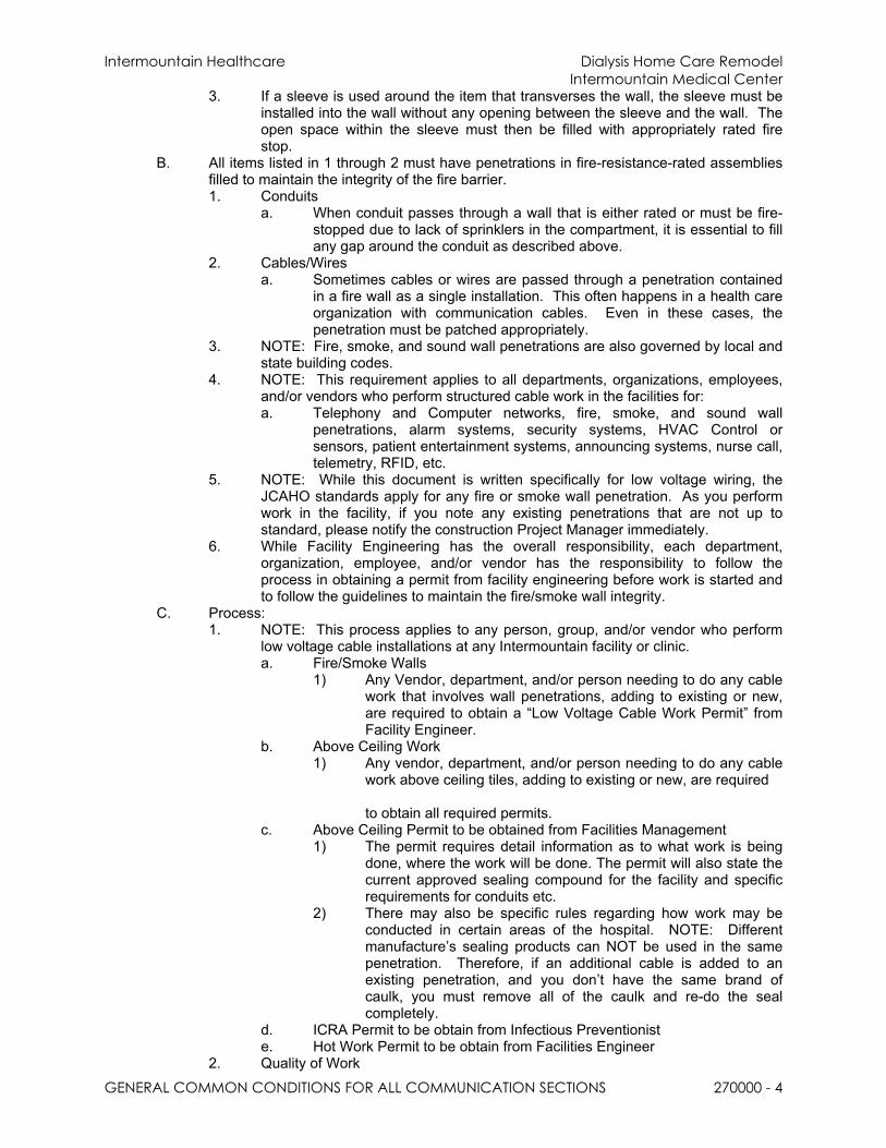
Intermountain Healthcare Dialysis Home Care RemodelIntermountain Medical Center
GENERAL COMMON CONDITIONS FOR ALL COMMUNICATION SECTIONS 270000 - 4
3. If a sleeve is used around the item that transverses the wall, the sleeve must be installed into the wall without any opening between the sleeve and the wall. The open space within the sleeve must then be filled with appropriately rated fire stop.
B. All items listed in 1 through 2 must have penetrations in fire-resistance-rated assemblies filled to maintain the integrity of the fire barrier.1. Conduits
a. When conduit passes through a wall that is either rated or must be fire-stopped due to lack of sprinklers in the compartment, it is essential to fill any gap around the conduit as described above.
2. Cables/Wiresa. Sometimes cables or wires are passed through a penetration contained
in a fire wall as a single installation. This often happens in a health care organization with communication cables. Even in these cases, the penetration must be patched appropriately.
3. NOTE: Fire, smoke, and sound wall penetrations are also governed by local and state building codes.
4. NOTE: This requirement applies to all departments, organizations, employees, and/or vendors who perform structured cable work in the facilities for:a. Telephony and Computer networks, fire, smoke, and sound wall
penetrations, alarm systems, security systems, HVAC Control or sensors, patient entertainment systems, announcing systems, nurse call, telemetry, RFID, etc.
5. NOTE: While this document is written specifically for low voltage wiring, the JCAHO standards apply for any fire or smoke wall penetration. As you perform work in the facility, if you note any existing penetrations that are not up to standard, please notify the construction Project Manager immediately.
6. While Facility Engineering has the overall responsibility, each department, organization, employee, and/or vendor has the responsibility to follow the process in obtaining a permit from facility engineering before work is started and to follow the guidelines to maintain the fire/smoke wall integrity.
C. Process:1. NOTE: This process applies to any person, group, and/or vendor who perform
low voltage cable installations at any Intermountain facility or clinic.a. Fire/Smoke Walls
1) Any Vendor, department, and/or person needing to do any cable work that involves wall penetrations, adding to existing or new, are required to obtain a “Low Voltage Cable Work Permit” from Facility Engineer.
b. Above Ceiling Work1) Any vendor, department, and/or person needing to do any cable
work above ceiling tiles, adding to existing or new, are required
to obtain all required permits.c. Above Ceiling Permit to be obtained from Facilities Management
1) The permit requires detail information as to what work is being done, where the work will be done. The permit will also state the current approved sealing compound for the facility and specific requirements for conduits etc.
2) There may also be specific rules regarding how work may be conducted in certain areas of the hospital. NOTE: Different manufacture’s sealing products can NOT be used in the same penetration. Therefore, if an additional cable is added to an existing penetration, and you don’t have the same brand of caulk, you must remove all of the caulk and re-do the seal completely.
d. ICRA Permit to be obtain from Infectious Preventioniste. Hot Work Permit to be obtain from Facilities Engineer
2. Quality of Work
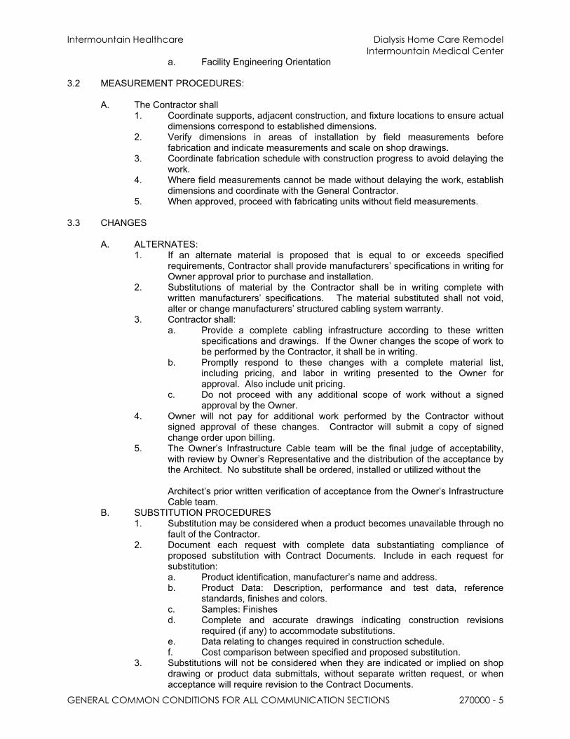
Intermountain Healthcare Dialysis Home Care RemodelIntermountain Medical Center
GENERAL COMMON CONDITIONS FOR ALL COMMUNICATION SECTIONS 270000 - 5
a. Facility Engineering Orientation
3.2 MEASUREMENT PROCEDURES:
A. The Contractor shall 1. Coordinate supports, adjacent construction, and fixture locations to ensure actual
dimensions correspond to established dimensions.2. Verify dimensions in areas of installation by field measurements before
fabrication and indicate measurements and scale on shop drawings. 3. Coordinate fabrication schedule with construction progress to avoid delaying the
work.4. Where field measurements cannot be made without delaying the work, establish
dimensions and coordinate with the General Contractor. 5. When approved, proceed with fabricating units without field measurements.
3.3 CHANGES
A. ALTERNATES:1. If an alternate material is proposed that is equal to or exceeds specified
requirements, Contractor shall provide manufacturers’ specifications in writing for Owner approval prior to purchase and installation.
2. Substitutions of material by the Contractor shall be in writing complete with written manufacturers’ specifications. The material substituted shall not void, alter or change manufacturers’ structured cabling system warranty.
3. Contractor shall:a. Provide a complete cabling infrastructure according to these written
specifications and drawings. If the Owner changes the scope of work to be performed by the Contractor, it shall be in writing.
b. Promptly respond to these changes with a complete material list, including pricing, and labor in writing presented to the Owner for approval. Also include unit pricing.
c. Do not proceed with any additional scope of work without a signed approval by the Owner.
4. Owner will not pay for additional work performed by the Contractor without signed approval of these changes. Contractor will submit a copy of signed change order upon billing.
5. The Owner’s Infrastructure Cable team will be the final judge of acceptability, with review by Owner’s Representative and the distribution of the acceptance by the Architect. No substitute shall be ordered, installed or utilized without the
Architect’s prior written verification of acceptance from the Owner’s Infrastructure Cable team.
B. SUBSTITUTION PROCEDURES1. Substitution may be considered when a product becomes unavailable through no
fault of the Contractor.2. Document each request with complete data substantiating compliance of
proposed substitution with Contract Documents. Include in each request for substitution:a. Product identification, manufacturer’s name and address.b. Product Data: Description, performance and test data, reference
standards, finishes and colors.c. Samples: Finishesd. Complete and accurate drawings indicating construction revisions
required (if any) to accommodate substitutions.e. Data relating to changes required in construction schedule.f. Cost comparison between specified and proposed substitution.
3. Substitutions will not be considered when they are indicated or implied on shop drawing or product data submittals, without separate written request, or when acceptance will require revision to the Contract Documents.

Intermountain Healthcare Dialysis Home Care RemodelIntermountain Medical Center
GENERAL COMMON CONDITIONS FOR ALL COMMUNICATION SECTIONS 270000 - 6
4. The Owner will be the final judge of acceptability, with review by Owner’s Representative and the distribution of the acceptance by the Architect.
5. No substitute shall be ordered, installed or utilized without the Architect’s prior written verification of acceptance from the Owner’s Infrastructure Cable team.
PART 4 - EXECUTION
4.1 QUALITY ASSURANCE
A. Regulatory Requirements:1. Contractor shall supply all city, county, and state telecommunication cabling
permits required by appropriate governing agency.2. Prior to commencing work, the Contractor and staff shall secure all required
Intermountain Healthcare permits including, but not limited to; facility sign in, ceiling work permits, hot work permits, and confined space permits.
3. Contractor shall be city, county, and state-licensed and/or bonded as required for communications/low voltage cabling systems work.
B. Certifications:1. Contractor shall submit an up-to-date and valid certification verifying
qualifications of the Contractor and installers to perform the work specified herein at time of bid submission.
2. Contractor shall have a complete working knowledge of low voltage cabling applications such as, but not limited to data, voice and video network systems.
3. Contracting firm shall have installed similar-sized systems in at least ten (10) other projects in the last five years prior to this bid and be regularly engaged in the business of installation of the types of systems specified in this document. Certification shall include, but not be limited to, items such as name and location of project contacts and numbers, total square footage, total number of cables/drops, types of media, etc.
4. Contractor shall provide certificates for the appropriate insurance coverage as defined in contract documents.
5. All installer personnel that will be assigned to this project shall be listed in a qualification document. 50% of the personnel working on the job site shall have a minimum of 3 years’ experience in the installation of the types of systems, equipment, and cables specified in this document. Any personnel substitutions shall be noted in writing to Owner’s Data Center Operations Infrastructure
Cabling representative prior to commencement of work.6. BICSI ITS Cabling Installation Program Installer Level 1 or 2 or Technician
certifications may be substituted in lieu of the 3-year requirement. All cabling installers shall be trained and certified by the cable manufacturer for communication cabling installations and maintenance of said materials.
7. Refer also to General Conditions.C. Administrative Requirements and Coordination:
1. The Contractor shall:a. Ensure that all technicians performing work have obtain badge access
48 hours prior to scheduled start.b. Provide a specified contact person (name and contact number) for
coordination to attend project meetings with the communication consultant, the Owner and others.
c. Coordinate work of this section with Owner’s system specifications, workstations, equipment suppliers, and installers.
d. Coordinate installation work with other crafts (examples include ceiling grid contractors, HVAC and sheet metal contractors, etc.) under the direction of the General Contractor to resolve procedures and installation placement for cable trays and cable bundle pathways. The goal of this coordination will be to establish priority pathways for critical data/voice network cable infrastructure, materials, associated hardware, as well as mitigate delays to the project and to allow service access for

Intermountain Healthcare Dialysis Home Care RemodelIntermountain Medical Center
GENERAL COMMON CONDITIONS FOR ALL COMMUNICATION SECTIONS 270000 - 7
communications and HVAC components. Damage by Contractor to the craftwork of others will be remediated at the Contractor’s expense in a timely manner.
e. Exchange information and agree on details of equipment arrangements and installation interfaces. Record agreements reached in meetings and distribute record to other participants, Owner and communication consultant.
f. Arrangement, layout, and locations of distribution frames, patch panels, and cross-connect blocks in equipment rooms and racks to accommodate and optimize arrangement and space requirements of any service provider equipment, telephone system, and LAN equipment as directed by Data Center Operations. Tasks shall be coordinated with the Owner’s Data Center Operations team, and other trades’ installation representatives.
g. Where installed, confirm exact locations and method of mounting outlets in modular furniture. Follow furniture manufacturers’ written instructions for installing cable and devices in modular partitions. Obtain modular furniture and power pole locations from the General Contractor. Wiring locations noted in plans along walls for modular furniture are approximate and will have to be determined by Contractor at time of installation. Field condition adjustments for installation may have to be made and coordination efforts with the mechanical and electrical contractor for pathway must take place early in the project to comply with maximum 40% conduit fill factor requirements.
h. When requested by Owner or Owner’s representative, furnish extra materials that match specified products and that are factory packaged with protective covering for storage and identified with labels describing contents. Unit pricing shall apply.
D. Contract Administration:1. Change orders shall be submitted to the Owner/Project Manager complete with
price breakdown and description for approval before any work is done.2. Owner’s Data Center Operations Representative will provide job field reports
upon inspection of Contractor's installation, materials, supporting hardware,
coordination with other trades and progress to schedule to the Owner’s project manager.
3. Job Field Report outline:a. General installation progress in relation to scheduled work made by the
Contractor up to that date.b. All deficiencies noted in the cable installation to be corrected by the
Contractor.E. Pre-Installation Meetings - Contractor shall:
1. Attend and/or arrange a scheduled pre-installation conference prior to beginning any work of this section.a. Agenda: This venue is to ask and clarify questions in writing related to
work to be performed, scheduling, coordination, etc. with consultant and/or project manager/and Data Center Operations Infrastructure Cabling representative.
b. Attendance: Communications project manager/supervisor shall attend meetings arranged by General Contractor, Owner’s Data Center Operations Infrastructure Cabling representatives, and other parties affected by work of this document.
c. All individuals who will be installers of communication cables and equipment in an on-site supervisory capacity shall be required to attend the pre-installation conference. Individuals who do not attend the conference will not be permitted to supervise the installation of, or install, terminate, or test communications cables on the project. This includes supervisors, project managers, and lead installers of this project.
F. Request for Change (RFC)

Intermountain Healthcare Dialysis Home Care RemodelIntermountain Medical Center
GENERAL COMMON CONDITIONS FOR ALL COMMUNICATION SECTIONS 270000 - 8
1. A Request for Change shall be opened and approved by the Change Approval Board prior to any modifications, attachments, or other activities that may affect production systems. a. Policy and details available through the Data Center Operations
Infrastructure Cable Representative.G. Post-Installation Meetings:
1. Schedule Div. 27 Final Inspection2. At the time of substantial completion, or shortly thereafter, the low voltage Sub-
Contractor shall call and arrange for a post-installation meeting to present and review all submittal documents to include, but not limited to as-built drawings, test reports, warranty documentation, etc. Attendees shall be Owner staff, Owner’s Representative, General Contractor, and others that the General Contractor deems appropriate.
3. At this meeting the Contractor shall present and explain all documentation, including test results, and ask for feedback on its completeness. Any discrepancies or deviations noted by and agreed to by participants shall be remedied by Contractor and resubmitted within one week of meeting.
4.2 DELIVERY, STORAGE, AND HANDLING:
A. Coordination with delivery companies, drivers, site address, and contact person(s) will be the responsibility of the Contractor.
B. Contractor Shall:1. Be responsible for prompt material deliveries to meet contracted completion date.2. Coordinate deliveries and submittals with the General Contractor to ensure a
timely installation.3. No equipment materials shall be delivered to the job site more than three weeks
prior to the commencement of its installation.4. Equipment shall be delivered in original packages with labels intact and
identification clearly marked.
5. Materials shall not be damaged in any way and shall comply with manufacturer’s operating specifications.
6. Equipment and components shall be protected from the weather, humidity, temperature variations, dirt, dust, or other contaminants. Equipment damaged prior to system acceptance shall be replaced at no cost to the Owner.
7. Material Contractor shall be responsible for all handling and control of equipment. 8. Material Contractor is liable for any material loss due to delivery and storage
problems.C. Owner/General Contractor shall supply a list of security requirements for Contractor to
follow.
4.3 PROJECT/SITE CONDITIONS
A. For all environmental recommendations, refer to master Architectural section.B. For all security recommendations, refer to related Division 01.C. After completing system installation, including outlet fittings and devices, inspect exposed
finish. Contractor will remove burrs, dirt, and construction debris. If applicable, the Contractor will repair damaged finishes, including chips, scratches, and abrasions.
D. Contractor shall provide daily a clean work environment, free from trash/rubbish accumulated during and after cabling installation.
E. Food and drink are not permitted in work areas. They shall be stored, prepared, and consumed only in designated break or cafeteria areas.
F. Contractor shall keep all liquids (drinks, sodas, etc.) off finished floors, carpets, and tiles. If any liquid or other detriment (cuts, soils, stains, etc.) damages the above finishes, Contractor shall provide professional services to clean or repair scratched/soiled finishes, at Contractor’s expense.

Intermountain Healthcare Dialysis Home Care RemodelIntermountain Medical Center
GENERAL COMMON CONDITIONS FOR ALL COMMUNICATION SECTIONS 270000 - 9
4.4 CLEANING
A. Work areas will be kept in a broom clean condition throughout the duration of the installation process.
B. Remove all unnecessary tools and equipment, unused materials, packing materials, and debris from each area where work has been performed daily, unless designated for storage.
C. The Contractor will damp clean all surfaces prior to final acceptance by Owner.
END OF SECTION

Intermountain Healthcare Dialysis Home Care RemodelIntermountain Medical Center
OPERATION AND MAINTENANCE OF COMMUNICATION SYSTEMS 270100 - 1
SECTION 270100 - OPERATION AND MAINTENANCE OF COMMUNICATIONS SYSTEMS
PART 1 - GENERAL
1.1 INTRODUCTION
A. To make the approval of such a large topic possible, the structured cable topic has been broken into its subcomponents and each subcomponent was completed, reviewed, and approved in turn. The result is this comprehensive guideline that should provide adequate guidance on this topic.
PART 2 - PRODUCT
2.1 KEY POINTS
A. Category 6A shielded foil over unshielded twisted pair (F/UTP) is the only approved standard for cabling.1. Specifically, Siemon category CAT6A F/UTP (foil over unshielded twisted pair)
cable and associated patch panels, wall plates and jacks; for data centers, and all clinical and hospital campus’.
2. Only Siemon certified contractors or certified Intermountain Healthcare cable technicians will install structured cable at Intermountain Healthcare facilities.
2.2 IMPLEMENTATION
A. This guide is to be used for New Construction and Remodels. These standards will be implemented over time in existing cabling environments as rework is performed.
B. If there is a current need to connect servers at 10GBaseT and the only option is copper, CAT6A F/UTP is required. New Server connections shall be a minimum OS1 Single Mode Fiber.
C. Installations already in place are not required to remove or replace existing cabling CAT5e or newer. All new cabling shall follow the recommendation to use CAT6A F/UTP cabling.
2.3 STANDARD PRODUCT
A. The Approved cable type for horizontal cabling is CAT 6A F/UTP.1. The Approved Standard Manufacturer for Intermountain Healthcare’s horizontal
cabling is:a. Siemon Company USA
101 Siemon Company DriveWatertown, CT 06795
2. Approved Suppliers of Siemon cable, patch panels, jacks, and parts are listed in Appendix 06:
PART 3 - EXECUTION
3.1 Horizontal Cabling
A. Horizontal Subsystem is the portion of the cabling system that extends from (and includes) the work area telecommunications outlet/connector to the Floor Distributor (FD)/Horizontal Cross-connect (HC) in the telecommunications room (TDR). It consists of the communications outlet/connector, the horizontal cable, optional consolidation point,
and that portion of the cross-connect in the telecommunications room serving the horizontal cable. Each floor of a building should be served by its own Floor

Intermountain Healthcare Dialysis Home Care RemodelIntermountain Medical Center
OPERATION AND MAINTENANCE OF COMMUNICATION SYSTEMS 270100 - 2
Distributor/Horizontal (FD/HC) Subsystem located in the telecommunications Room (TDR).1. NOTE: Cable installers have rigorous requirements to be certified for Siemon
cables and products. Validation of certification is required prior to accepting a bid.
2. Current Siemon Approved/Certified Cable Installers for Siemon Network are listed in Appendix 07.
B. Reliability of the horizontal cabling system is critical to the operation of IS equipment throughout a facility. Installing the cable is extremely labor intensive and there are several learned skills used to correctly install the cable. Cable installers are certified, and installers must demonstrate the ability to install the cable correctly to be certified. If the cable is installed by a certified installer and is installed in accordance with the manufacture’s guidelines, the manufacturer will warranty the cable installation.
C. The manufacturer also requires the cables to be individually labeled and 100% tested and certified. Cable testing and certification equipment is usually expensive and is not commonly available at the facility or by many telecom installers. Certified Installer companies are required by the manufacturer to be knowledgeable in the use of “Qualified” Field Testing equipment and provide test results for warranty registration.1. Contractor is to verify with the manufacturer the current “Qualified” tester
manufacturers and the current operating software.2. Contractors will provide test results in the operating software format (not PDF,
text or Word) to Intermountain Healthcare upon completion.D. Much of the cable is installed in walls and in the ceiling and usually lasts the lifespan of
the building. As with most technology, the lifespan of cable is its usability and applicability to its use on future computing technology.
END OF SECTION

Intermountain Healthcare Dialysis Home Care RemodelIntermountain Medical Center
WARRANTY, PRODUCT AND SYSTEM 270113 - 1
SECTION 270113 - WARRANTY, PRODUCT AND SYSTEM
PART 1 - GENERAL
1.1 RELATED DOCUMENTS
A. Drawings and general provisions of the Contract, including General and Supplementary Conditions and Division 01 Specification Sections, apply to this Section.
B. Specifications throughout all Divisions of the Project Manual are directly applicable to this Section, and this Section is directly applicable to them, including but not limited to the listing found in Section 27 00 00.
PART 2 - PRODUCTS
2.1 STANDARD WARRANTY
A. Contractor shall provide a minimum one (1) year warranty on installation and workmanship PLUS an Extended Product Warranty and System Assurance Warranty for this wiring system and shall commit to make available local support for the product and system during the Warranty period.
B. System Certification: Upon successful completion of the installation and subsequent inspection, the customer shall be provided with a Manufacture Warranty certificate.
C. Either a permanent link or channel model configuration may be applied to the horizontal and/or backbone sub-systems of the structured cabling system. Applications assurance is only applied to a channel model configuration. All channels are to be qualified for linear transmission performance up to 500 MHz to ensure that high-frequency voltage phase and magnitude contributions do not prove cumulative or adversely affect channel performance.
2.2 EXTENDED WARRANTY
A. The manufacturer of passive telecommunications equipment used in a manner not associated with the Systems Warranty must have a minimum five (5) year Component Warranty on all its product. The Products Warranty covers the components against defects in material or workmanship under normal and proper use.1. Special Project Warranty: A full end-to-end written warranty mutually executed by
manufacturer and the principal Installer, agreeing to replace and install voice/data distribution system components that fail in materials or workmanship, or do not meet manufacturer’s official published specifications and performance criteria within the special Project warranty period specified below. This shall cover applications assurance, cable, and connecting hardware including both labor and materials. This warranty shall be in addition to, and not a limitation of, other rights and remedies the Owner may have against the Contractor under the Contract Documents.
B. A twenty (20) year warranty available for the Category 6A Z-MAX copper structured cabling system shall be provided for an end-to-end channel model installation which covers applications assurance, cable, connecting hardware and the labor cost for the repair or replacement thereof. The fiber warranty will be an XGLO twenty (20) year warranty, which is based on using laser optimized single mode fiber as minimum.1. Performance claims based on worst case testing and channel configurations.2. Special Project Warranty Period: 20 years minimum, beginning on the date of
Substantial Completion.3. Siemon Certified Warranty Requirements:
Intermountain Healthcare Dialysis Home Care RemodelIntermountain Medical Center
WARRANTY, PRODUCT AND SYSTEM 270113 - 2
a. Upon Completion of the project, Intermountain Healthcare must receive the Full Warranty Documentation from The Siemon Company before final retention funds are released to the general contractor, electrical contractor and structured cabling subcontractor if applicable.
2.3 MAINTENANCE
A. Support Availability: The Contractor shall commit to make available local support for the product and system during the Warranty or Extended Warranty period.
END OF SECTION

Intermountain Healthcare Dialysis Home Care RemodelIntermountain Medical Center
FIELD TESTING AND REPORTING 270119 - 1
SECTION 270119 - FIELD TESTING AND REPORTING
PART 1 - GENERAL
1.1 RELATED DOCUMENTS
A. Drawings and general provisions of the Contract, including General and Supplementary Conditions and Division 01 Specification Sections, apply to this Section.
B. Specifications throughout all Divisions of the Project Manual are directly applicable to this Section, and this Section is directly applicable to them, including but not limited to the listing found in Section 27 00 00.
1.2 SYSTEM DESCRIPTION
A. Owner reserves the right to be present during any or all testing.B. The objective of this project is to provide a complete communications cabling
infrastructure system installation including, but not limited to: fiber backbone, riser system, horizontal data and voice cabling with associated terminations, mounting equipment, cable pathway and management systems, testing and other items/materials, as specified in drawings, these specifications, and contract documents.
C. The Contractor’s BICSI Registered Communications Distribution Designer (RCDD) supervisor shall review, approve and stamp all documents prior to submitting. The Contractor’s RCDD shall warrant in writing that 100% of the installation meets the requirements specified herein upon completion of all work.
D. Product Certificates shall be signed by manufacturers of cables, connectors, and terminal equipment certifying that products furnished comply with requirements.
E. Contractor shall submit the required Field Test Reports in the format and media specified, upon completion of testing the installed system.
F. Contractor shall deliver manufacturer’s signed long-term Warranty of installed cabling system to include all components that comprise the complete cabling system. Delivery to be affected within two weeks of the time of final punch list review. Failure of any component to pass system component tests shall be promptly corrected, repaired or replaced to meet standards compliance.
1.3 PREFERRED OWNER INSPECTION & TEST CHECKPOINTS
A. DCO & ICT Inspection Milestones & Responsibilities need to be coordinated into master project plan to allow the GC to make timely arrangements. All are per floor and/or phase.1. ICT & DCO = Framing, during and/or after boxes & conduits are in place;
prior to sheetrock. 2. ICT = When cable basket is starting to be installed.3. ICT = When cable basket is ready, but prior to starting to pull cable.4. ICT & DCO = When TDR’s are ready for racks and ladders.5. DCO = When anchoring racks and laying out equipment.6. ICT & DCO = When TDR environmental requirements are ready, room is
dust free, and securable.a. The TEC and TDRs must be high on the build timeline and be
completed early in the construction to accommodate the building systems to be tested and commissioned, such as BAS, Security, and Wireless Network.
7. ICT = When trim and testing are in progress.

Intermountain Healthcare Dialysis Home Care RemodelIntermountain Medical Center
FIELD TESTING AND REPORTING 270119 - 2
8. OTHERSa. Depending on project, the manufacturer will inspect 1 or 2 times.b. DCO or ICT = When problems or questions arise.
PART 2 - PRODUCTS
2.1 SITE TESTS & INSPECTIONS
A. Prior to pulling cable, the cabling contractor shall schedule an inspection of the pathways with a member of the Data Center Operations Infrastructure cabling team.
B. Upon completion of the communications infrastructure systems, including all pathways and grounding, the Contractor shall test the system. 1. Cables and termination modules shall be affixed, mounted or installed to
the designed/specified permanent location prior to testing. 2. Any removal and reinstallation of any component in a circuit, including
faceplates, shall require retesting of that circuit and any other disturbed or affected circuits.
3. Approved instruments, apparatus, services, and qualified personnel shall be utilized.
4. If tests fail, Contractor shall correct as required to produce a legitimate passing test.
5. Manipulation of tester parameters on a failing test in order to achieve a passing test is unacceptable.
C. These specifications will be strictly enforced. The Contractor must verify that the requirements of the specifications are fully met through testing with an approved tester (rated for testing the cable type in use), and documentation as specified below. This includes confirmation of requirements by demonstration, testing and inspection. Demonstration shall be provided at final walk-through in soft copy.
D. Notification of the likelihood of a cable exceeding standardized lengths must be made prior to installation of the cable. Without contractor’s prior written notice and written approval by the Owner, testing that shows some or all pairs of cable not meeting specifications, shall be replaced at Contractor’s expense (including respective connectors).
E. Testing is still required for non-compliant cabling. The tests shall be for wire-mapping, opens, cable-pair shorts, and shorts-to-ground. The test results must be within acceptable tolerances and shall be submitted with the Owner’s acceptance document.
2.2 CABLE TESTING PLAN
A. The Contractor shall:1. Provide a complete and detailed test plan for approval of the cabling
system specified herein, including a complete list of test equipment for copper and fiber optic components and accessories prior to beginning cable testing. The following minimal items shall be submitted for review:a. All testing methods that clearly describes procedures and
methods.b. Product data for test equipmentc. Certifications and qualifications of all persons conducting the
testing.

Intermountain Healthcare Dialysis Home Care RemodelIntermountain Medical Center
FIELD TESTING AND REPORTING 270119 - 3
d. Calibration certificates indicating that equipment calibration meets National Institute of Standards and Technology (NIST) standards and has been calibrated at least once in the previous year of the testing date.
2. Include validation, and testing. Owner will require that the telecommunications cabling system installed by the Contractor be fully certified to meet all necessary requirements to be compliant with referenced IEEE and TIA specifications and vendor’s warranty.
3. Will determine the source/cause of test failure readings and correct malfunctioning component and/or workmanship within each channel or permanent link and retest to demonstrate compliance until corrected failure produces a passing result.
2.3 CABLE TESTING REPORTS
A. The Contractor shall submit cable test reports as follows:
1. Submit certified test reports of Contractor-performed tests.a. The tests shall clearly demonstrate that the media and its
components fully comply with the requirements specified herein.b. (1) set of electronic test reports shall be submitted and clearly
identified with cable identification.
PART 3 - EXECUTION
3.1 TEST EQUIPMENT
A. All transmission testing of balanced twisted-pair cables shall be performed with an approved Level III balance twisted pair tester found on the Siemon Ally Website. The latest version of software shall be installed prior to performing testing. Refer to the Siemon Warranty Documents for proper testing requirements of associated cable and components.
B. All balanced twisted-pair field testers shall be factory calibrated each calendar year by the field test equipment manufacturer as stipulated by the manuals provided with the field test unit. The calibration certificate shall be provided for review prior to the start of testing
C. Auto test settings provided in the field tester for testing the installed cabling shall be set to the default parameters
D. Test settings selected from options provided in the field testers shall be compatible with the installed cable under test.
3.2 TEST METHOD / CRITERIA
A. Copper Testing1. Testing of all newly installed cable channels shall be performed prior to
system cutover.a. Visually inspect F/UTP and optical fiber cable jacket materials for
NRTL certification markings. Inspect cabling terminations in communications equipment rooms for compliance with color-coding for pin assignments and inspect cabling connections for compliance with TIA/EIA-568-C.1.
b. Visually confirm Category 6A marking of outlets, cover plates, outlet/connectors, and patch panels.
c. Visually inspect cable placement, cable termination, grounding and bonding, equipment and patch cords, and labeling of all

Intermountain Healthcare Dialysis Home Care RemodelIntermountain Medical Center
FIELD TESTING AND REPORTING 270119 - 4
components.d. Test F/UTP copper cabling for DC loop resistance, shorts, opens,
intermittent faults, and polarity between conductors. Test operation of shorting bars in connection blocks. Test cables after termination but not cross-connection.
e. Test instruments shall meet or exceed applicable requirements in TIA/EIA-568-C, and those required by manufacturer to validate and start warranty.
2. Copper Testing all 500 MHz category 6A field-testing shall be performed with an approved level 111e balanced twisted-pair field test device, that complies with performance requirements in "Test Instruments (Normative)" Annex, complying with measurement accuracy specified in "Measurement Accuracy (Informative)" Annex (Level IIe or IIIe balanced twisted pair field test device). Use only test cords and adapters that are qualified by test equipment manufacturer for channel or link test configuration.
3. All installed 500 MHz category 6A channels shall perform equal to or better than the minimum requirements as specified below:a. Category 3, balanced twisted-pair backbone cables, for the
channel shall be 100 percent tested according to ANSI/TIA/EIA-568-C.1. Test parameters include wire map plus F/UTP (ScTP) shield continuity (when present), insertion loss, length and NEXT loss (pair-to-pair). NEXT testing shall be done in both directions.
b. 500 MHZ Category 6A balanced twisted-pair horizontal and backbone cables, shall be 100 percent tested.
4. F/UTP Performance Testsa. Wire map.b. Length (physical vs. electrical, and length requirements)c. Insertion lossd. Near-end crosstalk (NEXT) losse. Power sum near-end crosstalk (PSNEXT) lossf. Equal-level far-end crosstalk (ELFEXT)g. Power sum equal-level far-end crosstalk (PSELFEXT)h. Return lossi. Propagation delayj. Delay skewk. F/UTP Shield continuity
5. Final Verification Tests: Perform verification tests for F/UTP systems after the complete communications cabling and workstation outlet/connectors are installed.
6. Document data for each measurement. Data for submittals shall be printed in a summary report.
7. End-to-end cabling will be considered defective if it does not pass tests and inspections.
8. Prepare and submit test and inspection reports.B. Horizontal Fiber Testing
1. Fiber horizontal cables shall be 100% tested for insertion loss and length.2. Insertion loss shall be tested at 850 nm or 1300 nm for 50/125µm and
62.5/125µm multimode cabling in at least one direction using the Method B (1-jumper) test procedure as specified in ANSI/TIA/EIA-526-14A.
3. Length shall be tested using an OTDR, optical length test measurement device or sequential cable measurement markings.
4. The horizontal link performance guarantees are based on an optical fiber

Intermountain Healthcare Dialysis Home Care RemodelIntermountain Medical Center
FIELD TESTING AND REPORTING 270119 - 5
calculation for the appropriate fiber solution. Optical fiber calculations shall be determined using the Siemon Fiber Loss Calculator found on the Siemon Ally Website.
C. Backbone Fiber Testing 1. Fiber backbone cables shall be 100% tested for insertion loss. 2. Insertion loss shall be tested at both 850 nm and 1300 nm for 50/125µm
and 62.5/125µm multimode cabling and both1310 nm and 1550 nm for 8.5/125µm single mode cabling and in at least one direction using the Method B (1-jumper) test procedure as specified in ANSI/TIA/EIA-526-14A.
3. Insertion loss shall be tested at 1310 and 1550 for single-mode cabling in at least one direction using the Method A.1 (1-jumper) test procedure as specified in ANSI/TIA/EIA-526-7.
4. Length shall be tested using an OTDR, optical length test measurement device or sequential cable measurement markings.
5. The backbone link performance guarantees are based on an optical fiber calculation for the appropriate fiber solution. Optical fiber calculations for any fiber cable greater than 90m (295 ft.) shall be determined using the Siemon Fiber Loss Calculator found on the Siemon Ally Website.
3.3 DEMONSTRATION
A. Include training for appropriate IT staff in numbering system and documentation system methods and record keeping. Proper fiber terminations and fiber jumper installations.
END OF SECTION

Intermountain Healthcare Dialysis Home Care RemodelIntermountain Medical Center
SHOP DRAWINGS PRODUCT DATA SAMPLES DESIGN RECORDS 270133 - 1
SECTION 270133 - SHOP DRAWINGS, PRODUCT DATA, SAMPLES DESIGN RECORDS & EXISTING CONDITIONS
PART 1 - SHOP DRAWINGS, PRODUCT DATA, AND SAMPLES
1.1 SUBMITTALS
A. The Contractor:1. Shall not perform any portion of the work requiring submittal and review of
shop drawings, product data, or samples until Owner has approved the respective submittal. Such work shall be in accordance with approved submittals.a. Shop drawings as required by the owner or as a minimum to
include a minimum of two sets of a plan view and elevations of all work to be installed. The Contractor shall make any corrections required by the owner or the owner’s representative or consultant team, file with him two corrected copies and furnish such other copies as may be needed. The consultant’s approval of such drawings or schedules shall not relieve the Contractor from responsibility for deviations from drawings or specifications, unless he has in writing and called to the Architect's attention such deviations at the time of submission, nor shall it relieve him from responsibility for errors of any sort in shop drawings or schedules.
B. The Contractor shall provide a copy of the Certified Test Data Sheet, available from the delivering distribution warehouse for either a full run or cut piece from the Master Reel of the fiber cable to be installed1. The Certified Test Data Sheet shall include the Master Reel number, cable
description, a passing test result with details, test equipment description, date certified, and a certificate of compliance stamp, and shall be included in the O&M Manual as a component of the final deliverables submittal package.
1.2 DRAWINGS
A. Shop Drawings1. The Contractor shall:
a. Submit catalogue cut sheets that include manufacturer, trade name, and complete model number for each product specified. Model number shall be handwritten, marked with an arrow or underlined to indicate exact selection.
b. Identify applicable specification section reference for each product performance for each component specified for approval prior to purchase and installation.
B. Record Drawings1. Drawings for the cabling system infrastructure elements shall be
maintained and kept on file by the Siemon Certified Installer (Company) for the entire term of the warranty. Drawings shall include:a. Horizontal cable routing and terminationsb. Telecommunications outlets/connectorsc. Backbone cable routing and terminationsd. Telecommunication Spaces (TS)
C. Samples

Intermountain Healthcare Dialysis Home Care RemodelIntermountain Medical Center
SHOP DRAWINGS PRODUCT DATA SAMPLES DESIGN RECORDS 270133 - 2
1. For workstation outlet connectors, jack assemblies, housing and faceplates for color selection and evaluation of technical specifications and requirements. Confirm with Architect, interior designer, and Owner representative for color before purchasing materials. Face plates shall match the electrical face plates in
Color and material type.2. Upon request, provide samples for workstation outlets, jacks, jack
assemblies, in specified finish, one for each size and outlet configuration 3. Sample mock-up rooms may be required in some areas to ensure proper
equipment placement and fit.D. Qualifications:
1. The Contractor shall provide the appropriate documentation to comply with the requirements set forth in Section 01 43 23 Qualifications, included with, and at the time of, bid submittal.
PART 2 - SUSTAINABLE DESIGN RECORDS AND REPORTS
2.1 DRAWINGS
A. Closeout Submittals (As-built Drawings):1. Communications Design drawings are to be supplied to the Architect to
prepare the master “As-Built” drawings.2. As-Built drawings shall be in a format that is compatible with the format
used by the Architect and consultant. Dimensions and scale of the drawing sheets submitted shall match the size of the drawing used for the contract documents and shall include the cable numbers labeled in accordance with this document.
3. Utilize normal recognized drafting procedures that match standards, Architect and consultant guidelines and methodology.
4. The As-Built drawings shall incorporate all changes made to the building identified in, but not limited to, addendum, change notices, site instructions or deviations resulting from site conditions.
B. Contractor shall:1. Clearly identify any resubmitted drawing sheets, documents or cut sheets
either by using a color to highlight or cloud around resubmitted information.
2. Maintain drawing numbering or page/sheet scheme consistency as per previously issued drawings/documents.
3. Provide dimensioned plan and elevation views of networking components, showing:a. All communications data/voice outlet locations complete with
outlet/cable labeling.b. Cable routing paths of communications cables to identified
infrastructure pathways.c. All rack and cabinet locations and labeling thereof.d. One-line diagram of equipment/device interconnecting
data/voice cabling of the data and voice systems.e. Standard or typical installation details of installations unique to
Owner’s requirements.f. Graphic symbols and component identification on detail drawing
shall conform to the latest ANSI/TIA 568-C, ANSI/TIA 569-B, ANSI/TIA 606-A and ANSI/NECA/BICSI 607-A conventions.

Intermountain Healthcare Dialysis Home Care RemodelIntermountain Medical Center
SHOP DRAWINGS PRODUCT DATA SAMPLES DESIGN RECORDS 270133 - 3
4. Submit one soft (compatible with Microsoft software) and hard copy with project deliverables within three weeks subsequent to substantial completion.
5. Hard copy of floor plans for record shall be plotted to a standard, saleable, identified drawing scale.
2.2 RECORDS AND REPORTS
A. All records shall be created by the installation contractor and turned over at the completion of work.1. The format shall be computer based
a. Soft copies and hard copies shall be part of the As-built package. b. The minimum requirements include:
1) Cable records must contain the identifier, cable type, termination positions at both ends, splice information as well as any damaged pairs/conductors.
2) Connecting hardware and connecting hardware position records must contain the identifier, type, damaged position numbers, and references to the cable identifier attached to it.
2. Test documentation on all cable types shall be included as part of the As-built package.
B. All Siemon Warranty Registration documents shall be included.C. All reports shall be generated from the computer-based program used to create
the records above. These reports should include but not limited to:1. Cable Reports2. Cross-connect Reports3. Connecting Hardware Reports
PART 3 - EXISTING CONDITIONS SITE SURVEY
3.1 SITE SURVEY
A. Prior to placing any cable pathways or cable, the contractor shall survey the site to determine job conditions will not impose any obstructions that would interfere with
B. the safe and satisfactory placement of the cables. The arrangements to remove any obstructions with the Project Manager need to be determined at that time.
END OF SECTION

Intermountain Healthcare Dialysis Home Care RemodelIntermountain Medical Center
QUALIFICATIONS AND REQUIRED TRAINING FOR CONTRACTOR AND INSTALLER 270143 - 1
SECTION 270143 - QUALIFICATIONS AND REQUIRED TRAINING FOR CONTRACTORS AND INSTALLERS
PART 1 - GENERAL INSTALLLER QUALIFICATIONS
1.1 ENTITIES
A. Communications contractors1. The Communications Contractor shall at a minimum possess the following
qualifications:a. Contractor shall be a Siemon Certified Contractor with valid up to date
contract certification and in good standing with the Siemon Company.b. Be in business a minimum of five (5) years.c. Contractor shall demonstrate satisfaction of sound financial condition
and can be adequately bonded and insured if the project deems necessary.
d. Possess those licenses/permits required to perform telecommunications installations in the specified jurisdiction.
e. Use personnel knowledgeable in local, state, province and national codes and regulations. All work shall comply with the latest revision of the codes or regulations. When conflict exists between local or national codes or regulations, the most stringent codes or regulations shall be followed.
2. Contractor must possess current liability and workers compensation insurance certificates.
3. Contractor must be registered with BICSI and have at least one RCDD on staff or ITS Cabling Installer Program Technician certification and Installer Level 1 & 2 for a minimum of 75 percent of staff.
1.2 TRAINING
A. The Contractor shall be fully conversant and capable in the cabling of low voltage applications such as, but not limited to data, voice and imaging network systems. The Contractor shall at a minimum possess the following qualifications:1. Personnel trained and certified in the design of the Siemon Cabling System®.2. Personnel trained and certified to install the Siemon Cabling System®.3. The Designer and Installer shall show proof of current certification of the Siemon
Cabling System® via an updated certificate given after attending the Certified Installer training course or an on-line re-certification class given every two years.
4. Provide references of the type of installation provided in this specification.5. Personnel trained and certified in the installation of copper cable and in the use
of Level IIIe Copper Transmission Performance testers, fiber optic cabling, splicing, termination and testing techniques. Personnel must have experience using an optical light source and power meter plus an OTDR.
6. Personnel trained in the installation of pathways and supports for housing horizontal and backbone cabling.
B. Facilities Orientation
END OF SECTION

Intermountain Healthcare Dialysis Home Care RemodelIntermountain Medical Center
RESPONSIBILITY AND WORKMANSHIP OF CONTRACTOR 270171 - 1
SECTION 270171 - RESPONSIBILITY AND WORKMANSHIP OF CONTRACTOR
PART 1 - GENERAL
1.1 CONTRACTOR RESPONSIBILITY
A. Contractor shall be obligated to exercise the highest standard of care in performing its obligations as defined in a request for proposal. All work shall be done in a workman like fashion of the highest standards in the telecommunications industry.
B. All equipment and materials are to be installed in a neat and secure manner, while cables are to be properly dressed in accordance with standards recommendation for a specific type of media (i.e. UTP vs. F/UTP @ 10 Gigabit)
C. Workers must clean any debris and trash at the close of each job and workday.D. Contractor acknowledges that Intermountain Healthcare will rely on contractor’s
expertise, ability and knowledge of the system being proposed and shall be obligated to exercise the highest standard of care in performing contractual obligation as defined in the Scope of Work.
E. Contractor must submit The Siemon warranty, Cable Records, As Built Drawings and Test Results at the completion of work. Note: Intermountain Healthcare reserves the right to withhold final payments until all registration documents are approved by the Siemon Company and received by Intermountain Healthcare.
1.2 CONTRACTOR AND EMPLOYEE RESPONSIBILITY
A. Contractors, their employees, and installers will attend annually Intermountain Healthcare required Infection Control training.
B. Contractors, their employees, and installers will complete Reptrax registration.C. Contractors, their employees, and installers will attend Intermountain Healthcare required
site and job specific orientation.D. Contractors, their employees, and installers will maintain Intermountain Healthcare
required immunizations.E. Contractors, their employees, and installers will keep their Intermountain Healthcare
required confidentiality agreements current.F. Contractors, their employees, and installers always agree to follow all Intermountain
Healthcare Policies and procedures and wear the appropriate ID while on any of Intermountain properties.
G. Contractor will determine with Owner the appropriate level of Environmental Containment precautions to utilize for each work location. Infection Control Risk Assessments and permits will be performed as required.
H. Upon request, provide qualification data for all qualified layout technicians, installation supervisors, and field inspector1. Siemon issued qualification badges shall be readily available for this purpose.
1.3 EXAMINATION
A. Field Measurements: Verify dimensions in areas of installation by field measurements before fabrication and indicate measurements on shop drawings. Coordinate fabrication schedule with construction progress to avoid delaying the work.
B. Established Dimensions: Where field measurements cannot be made without delaying the work, establish dimensions and proceed with fabricating units without field
measurements. Coordinate supports, adjacent construction, and fixture locations to ensure actual dimensions correspond to established dimensions.
1.4 PREPARATION
A. Pre-installation inspection

Intermountain Healthcare Dialysis Home Care RemodelIntermountain Medical Center
RESPONSIBILITY AND WORKMANSHIP OF CONTRACTOR 270171 - 2
1. The Contractor shall visually inspect all cables, cable reels, and shipping cartons to detect possible cable damage incurred during shipping and transport. Visibly damaged goods are not acceptable and shall be replaced by the contractor at no additional cost to the Owner.
1.5 MISCELLANEOUS CONTRACTOR RESPONSIBILITIES
A. Contractor will maintain unobstructed egress in work areas.B. Contractor will keep an access for all Emergency Services.C. Contractor will maintain training for Personnel in alternate exits if needed.D. Contractor will maintain Temporary construction partitions, as required, that are smoke
tight and built of non-combustible materials.E. Additional Fire Extinguishers may be required and will be properly maintained and
inspected.F. Construction site will be maintained clean and orderly.G. Contractor will observe Intermountain Healthcare’s Tobacco Use Policy. (All forms of
tobacco use are strictly prohibited)H. All Electrical Extension cords will be grounded, and in good condition and, plugged into
approved GFI Receptacles.I. Construction site will be restricted. (Approved personnel Only)J. Required Personal Protective Equipment (PPE) will be worn as required. (i.e. hard hats,
safety glasses, safety shoes, fluorescent vest, in accordance with general contractor's safety policy)
K. Tools will be unplugged, and power secured at the end of each working day.L. All employees and contractors will understand how to obtain MSDS sheets.M. Contractor will notify proper personnel of any fire system shut down. A 48-hour
notification is required.N. Contractor will address all vibration concerns with Intermountain Healthcare and general
contractor's staff.O. Contractor will address all Noise Issues with Intermountain Healthcare and general
contractor's staff.P. Contractor will fill out a Hot Work permit and keep it on site daily as needed.Q. Contractor will fill out an Above Ceiling Work Permit and keep it on site daily as needed.R. Contractor will obtain a Confined Space Permit, when required, and keep it on site. S. Contractor shall notify Information Systems 72 hours in advance of any shutdown or
known interruption of required environmental services. Follow up by notifying the Service Desk.
T. Demolition of low voltage cabling shall be performed by the Low Voltage installation contractor.1. To prevent accidental removal of in-use circuits.2. To allow for re-use of circuits where practical.
END OF SECTION

Intermountain Healthcare Dialysis Home Care RemodelIntermountain Medical Center
COMMON WORK RESULTS FOR COMMUNICATIONS 270500 - 1
SECTION 270500 - COMMON WORK RESULTS FOR COMMUNICATONS
PART 1 - PRODUCT
1.1 SUMMARY
A. This section covers general work results for all Communications Division detail subsections.
B. Work of the following sections cover a complete installation of both permanent and channel links for a data and voice communications network utilizing copper and fiber transmission media.
PART 2 - EXECUTION
2.1 SCOPE OF WORK
A. Includes, but is not limited to the following. 1. The Contractor shall:
a. Provide and install fabric and/or either plenum, PE or PVC Innerduct, rated appropriately for the installation environment; in accordance with all applicable codes and ordinances.
b. Provide, install, terminate, test, label and document all fiber backbone, fiber and copper riser cable.
c. Provide, install, terminate, test, and document all fiber, copper voice, and data horizontal cable.1) CAT6A UTP and CAT6A F/UTP shall not be mixed on the same
campus.d. Provide and place all termination devices such as, but not limited to,
modular patch panels, termination blocks, information outlets (jacks and plates), phone jacks, fiber distribution panels, bulkheads, connectors, and fiber fan out kits.
e. Provide in quantities specified interconnect components such as, but not limited to, copper patch cords, fiber patch cables and data station cables.
f. Provide and place horizontal and vertical cable support devices such as, but not limited to, rack and wall-mounted horizontal and vertical cable management, cable runway, communications cable runway, and all required mounting hardware, unless otherwise noted.
g. Provide and install all equipment mounting racks, cabinets and/or brackets.
h. Provide and install UL-approved fire stopping systems in all communication pass-thru, conduits, cable trays and ceiling, wall and floor penetrations in coordination with General Contractor.
i. Provide all appropriate consumable items required to complete the installation.
j. Grounding and bonding in TEC and TR rooms to grounding bus provided by Division 26.
k. Provide complete documentation and demonstration of work.l. Completion of all punch list deficiencies within 10 working days.m. Provide indexed and organized complete Test Results of all copper and
fiber cable and their components.n. Provide Submittals.

Intermountain Healthcare Dialysis Home Care RemodelIntermountain Medical Center
COMMON WORK RESULTS FOR COMMUNICATIONS 270500 - 2
o. Conduct a final document handover meeting with client, consultant, and PM to review, discuss and educate the Owner on the test results and As-Built Drawings.
p. Provide a Manufacturer’s Extended Product Warranty and System Assurance Warranty for this wiring system.
END OF SECTION

Intermountain Healthcare Dialysis Home Care RemodelIntermountain Medical Center
GROUNDING AND BONDING FOR COMMUNICATIONS SYSTEMS 270526 - 1
SECTION 270526 - GROUNDING AND BONDING FOR COMMUNICATIONS SYSTEMS
PART 1 - GENERAL
1.1 RELATED DOCUMENTS
A. This work shall be provided by Division 26.1. Division 26 shall provide and install the communications system grounding bus
bar.2. Systems other than the voice/data system shall be bonded by their respective
installers or Division 26.B. Exception: Division 27 shall bond racks, ladders, and other conductive IT equipment and
enclosures as required.C. Requirements of the following Division 26 Sections apply to this section:
1. Basic Electrical Requirements2. Basic Electrical Materials and Methods3. Grounding and Bonding for Electrical Systems
1.2 SUMMARY
A. This Section includes methods and materials for grounding and bonding Communications systems.
B. All grounding / earthing and bonding shall be done to applicable codes and regulations. It is recommended that the requirements of IEC/TR 61000-5-2: 1.0, ANSI-J-STD-607-A, or both be observed throughout the entire cabling system.
PART 2 - PRODUCTS
2.1 CONDUCTORS
A. Insulated Conductors: Copper wire or cable insulated for 600 V unless otherwise required by applicable Code or authorities having jurisdiction.1. Stranded conductors No. 6 AWG.
2.2 CONNECTORS
A. Listed and labeled by a nationally recognized testing laboratory acceptable to authorities having jurisdiction for applications in which used, and for specific types, sizes, and combinations of conductors and other items connected.
B. Compression fitting – 2-hole strap.
PART 3 - EXECUTION
3.1 QUALITY ASSURANCE
A. Electrical Components, Devices, and Accessories: Listed and labeled as defined in NFPA 70 (NEC), Article 100, by a testing agency acceptable to authorities having jurisdiction, and marked for intended use.
B. Comply with UL 467 for grounding and bonding materials and equipment.
3.2 APPLICATIONS
A. Conductors: Install stranded conductors for No. 6 AWG and larger, unless otherwise indicated.

Intermountain Healthcare Dialysis Home Care RemodelIntermountain Medical Center
GROUNDING AND BONDING FOR COMMUNICATIONS SYSTEMS 270526 - 2
3.3 INSTALLATION
A. Grounding Conductors 1. Route along shortest and straightest paths possible, unless otherwise indicated
or required by Code. 2. Avoid obstructing access or placing conductors where they may be subjected to
strain, impact, or damage.a. Jumper across all tray junctions use two-hole crimp lugs with a bolt, lock
washer and nut to prevent loosening of ground connections over time.b. Contractor to remove small area of powder coat or paint to create a
metal to metal bonding connection.c. Per current BICSI TDMM "Grounding, Bonding and Electrical Protection":
1) Grounding and bonding connectors should be one of the following: Tin plated copper, copper or copper alloy
2) Connections should be made using crimp connectors, or exothermic welding.
d. Per TIA/EIA 607-A the TBB (Telecommunications Bonding Backbone) connections "shall be made using irreversible compression-type connectors, exothermic welding or equivalent."
END OF SECTION

Intermountain Healthcare Dialysis Home Care RemodelIntermountain Medical Center
PATHWAYS FOR COMMUNICATIONS SYSTEMS 270528 - 1
SECTION 270528 - PATHWAYS FOR COMMUNICATONS SYSTEMS
PART 1 - GENERAL
1.1 RELATED DOCUMENTS
A. Main pathways for communications systems shall be the responsibility of the Division 27 low voltage contract.1. Includes, but is not limited to, hangars, supports, J-hooks and cable tray.2. Sections 270536, 270539, and 270543_46, are supplemental clarifications
that are additions to this section. The appropriate section(s) shall add for the material used.
B.Conduits, pathways, and boxes which are embedded within building finishes for communications systems shall be the responsibility of the Division 26 electrical contractor
C. Requirements of the following Division 26 sections apply to this section1. Basic electrical requirements2. Basic electrical materials and methods3. Grounding, earthing, and bonding for electrical systems
1.2 SUMMARY
A. Contractor shall install work following specifications, drawings, manufacturer’s instructions and approved submittal data.
PART 2 - PRODUCTS
2.1 CABLE PATHWAYS
A. Comply with TIA/EIA-569-B.B.Pathways shall be designed and installed to meet applicable local and national
building and electrical codes or regulations.1. All materials shall be UL- and/or CSA and/or ETL-approved and labeled in
accordance with NEC for all products where labeling service normally applies.
2. NRTL labeled for support of Category 6A cabling, designed to prevent degradation of cable performance and pinch points that could damage cable
3. Materials and equipment requiring UL 94, 149 or 1863 listing shall be so labeled. Modification of products that nullifies UL labels are not permitted.
4. The installed systems shall not generate, nor be susceptible to any harmful electromagnetic emission, radiation, or induction that degrades, or obstructs any equipment.
C. Pathways consist of conduit, basket tray/ladder rack, J-hooks, surface mounted raceway and power poles. 1. Basket tray shall be utilized for distribution pathways
a. Provides proper support and load distribution along pathways.b. Flexibility, scalability, and accessibilityc. Ladder rack shall be used in data rooms.
2. Conduits may be utilized where cable tray is not viable, providing the cross-sectional area of the conduit is greater than the cross-sectional area of the cable tray.

Intermountain Healthcare Dialysis Home Care RemodelIntermountain Medical Center
PATHWAYS FOR COMMUNICATIONS SYSTEMS 270528 - 2
3. J-hooks are the minimum pathway device required for all low voltage contractors for use in ceiling distribution. a. Refer to section 270529.
4. Note: Surface mounted raceway and power poles should be installed only when
other pathway choices are not feasible.
2.2 EQUIPMENT
A. Compatibility1. All material and equipment as provided should be the standard
Commercial-Off-The-Shelf (COTS) products of a manufacturer engaged in the manufacturing of such products. All shall be typical commercial designs that comply with the requirements specified. All material and equipment shall be readily available through manufacturers and/or distributors.a. All equipment shall be standard catalogued items of the
manufacturer and shall be supplied complete with any optional items required for proper installation.
b. Coordinate the features of materials and equipment so they form an integrated system. Match components and interconnections for optimum future performance and backward compatibility
B.Horizontal cables shall be installed in “clean, dry” locations that provide protection from moisture levels above the intended operating range of inside plant (ISP) cables1. Cable pathways shall be installed to provide protection from the elements
(i.e. moisture) and other hazards.2. Cables and cable pathways shall be protected from detritus elements
such as paints, adhesives, water and cleaners.a. In case of contamination, cables shall be replaced at the General
Contractors expense. Cleaning is not acceptable.3. Pathways shall not have exposed sharp edges that may come into
contact with telecommunications cables.C. Pathways shall not be in elevator shafts.D. Grounding / Earthing and bonding of pathways shall comply with applicable
codes and regulations. It is recommended that the requirements of IEC/TR3 61000-5-2 - Ed. 1.0, ANSI-J-STD-607-B, or both be observed throughout the entire cabling system.
2.3 SURFACE MOUNTING
A. Surface Mount Cable Runs and Faceplate Boxes1. Surface mounting of cable pathway runs and/or boxes for
outlets/faceplates are only authorized as a last resort and exception to running cables through the wall and above the ceiling.
2. If surface mount cable runs are used:a. Burrs will be removed from the inside of the plastic or metal surface
mount pathway to prevent damage to cables pulled through the run.
b. Raceway manufacturer plastic bushings shall be installed at all outlet openings in raceway to prevent damage to cable.
c. “T”, Splice, and corner pieces will be used to join runs. Runs will not be butted together without the appropriate joining pieces.

Intermountain Healthcare Dialysis Home Care RemodelIntermountain Medical Center
PATHWAYS FOR COMMUNICATIONS SYSTEMS 270528 - 3
PART 3 - EXECUTION
3.1 HORIZONTAL PARAMETERS
A. Allowable Cable Bend Radius and Pull Tension:1. In general, communications cable cannot tolerate sharp bends or
excessive pull tension during installation. a. Bend radius for 4 pair UTP and F/UTP under no load (no pulling
tension) shall not exceed four (4) times the outside diameter of the cable and eight (8) times the outside diameter of the cable under load (110N/25lbf). Note: Cable bend radius and pulling tensions for cables other than 4 pair
cable increase with the diameter and type of cable refer to the manufacturer’s recommendations for specific requirements.
2. After installation, exposed cable and other surfaces must be cleaned free of lubricant residue. Use only lubricants specifically designed for cable installation.
B.Pull Strings:1. Horizontal and Vertical Pathways
a. The pathway installer shall:1) Provide pull strings in all new conduits, including all conduits
with cable installed as part of this contract.2) Provide pull strings in all new cable trays.3) Pull string shall have a rated average breaking strength of
200 pounds.4) During pulling sessions, pull strings must move freely to
prevent cable jacket/cable damage.5) Free moving pull strings shall be provided in all locations
where they are utilized as part of this contract.C. Conduit Fill:
1. Reference manufacturer's Design Installation Guidelines manual.2. Comply with requirements of NFPA 70 (NEC)3. The number of cables placed in a pathway shall not exceed manufacture
specifications, nor, will the geometric shape of a cable be affected.a. Conduit pathways shall have a maximum fill ratio of 40% to allow
for proper pulling tension and lay of the CAT6A F/UTP cable. A minimum of a 1” diameter conduit is required for new construction. Existing conduits will require the reduction of the number of cables placed in the conduit to meet the required fill ratio.
3.2 INTRA-BUILDING CABLE ROUTING
A. Pathways1. The backbone subsystem shall include cable installed in a vertical manner
between floor telecommunications rooms and the main or intermediate cross-connect in a multi-story building and cable installed horizontally between telecommunications rooms and the main or intermediate cross-connect in a long single-story building.
2. Adequate riser sleeve/slot space shall be available with the ability to ingress the area later in all telecommunications rooms, such that no drilling of additional sleeves/slots is necessary. Proper fire stopping is required for all sleeves/slots per national and local codes. Install fire stop material designed specifically for the building construction conditions and to meet the existing fire stop material as directed by the building engineer.
Intermountain Healthcare Dialysis Home Care RemodelIntermountain Medical Center
PATHWAYS FOR COMMUNICATIONS SYSTEMS 270528 - 4
3. Backbone pathways shall be installed or selected such that the minimum bend radius of backbone cables is kept within manufacturer specifications both during and after installation.
4. Where redundant paths are required, they shall be separated by a minimum of 24”.a. Separate innerducts and/or armored fiber are required for each
leg of the redundant path.b. Separate physical routing for each path shall be utilized where
possible.5. Building backbone cables shall be installed in “dry” locations that provide
protection from moisture levels above the intended operating range of inside plant (ISP) cables. “Slab-on-Grade” building designs wherein pathways are installed underground on/in the poured concrete slabs that are in direct contact with the soil are considered wet locations and hence are not permitted.
END OF SECTION

Intermountain Healthcare Dialysis Home Care RemodelIntermountain Medical Center
HANGERS AND SUPPORTS FOR COMMUNICATIONS SYSTEMS 270529 - 1
SECTION 270529 - HANGERS AND SUPPORTS FOR COMMUNICATION SYSTEMS
PART 1 - PRODUCTS
1.1 APPROVED PRODUCT
A. The J-hooks shall meet or exceed the below characteristics of construction and features1. Provide broad based support for cabling to aid in maintaining overall system
performance.2. Be available in 50.8mm (2”) and 101.6mm (4”) options3. Come equipped with a cable retention clip4. Offers a full line of mounting accessories.
1.2 APPROVED MANUFACTURERS
A. Ericson / CaddyB. B-LineC. Stiffy
PART 2 - EXECUTION
2.1 J-HOOKS AND OTHER SUPPORTS SHALL BE INSTALLED SUCH THAT THEY:
A. Shall be supported with devices designed for this purpose and shall be installed independently of any other structural component. J-Hooks shall not use the suspended ceiling support wires or lighting fixture support wires.
B. The number of cables placed into the J-hooks shall be limited to a number that will not cause a change to the geometric shape of the cables.1. Limit to a 40% fill in new construction.
C. J-hooks shall not be spaced farther than 1.5 meters (5 ft.) apart, with a recommendation that they be space at 1 meter (3 ft.) apart. Note: Construction may require distances to exceed the maximum and are considered an exception requiring approval of project manager or building engineer.
D. J-hooks or better must be installed without exception.
2.2 UNACCEPTABLE INSTALLATIONS
A. Free flight of cablesB. Resting or attaching of cables on pipes, conduits, HVAC duct work, fire sprinkler
systems, basket tray, basket tray supports or on the ceiling tiles/grid.
END OF SECTION

Intermountain Healthcare Dialysis Home Care RemodelIntermountain Medical Center
CONDUITS AND BACK BOXES FOR COMMUNICATION SYSTEMS 270533 - 1
SECTION 270533 - CONDUITS AND BACK BOXES FOR COMMUNICATION SYSTEMS
PART 1 - GENERAL
1.1 RELATED DOCUMENTS
A. Division 26 – Electrical work
PART 2 - PRODUCTS
2.1 APPROVED PRODUCT
A. Conduits and Back boxes shall meet the construction requirements of the NEC for the type of structure and space in which they are installed and will be of the diameter and size to provide adequate fill, bend radius and connector space. Refer to section 270528.
PART 3 - EXECUTION
3.1 CONDUIT SIZING
A. Conduit size shall be based on the type of cable installed and the required fill ratio and bend radius associated with the type of cable specified. 1. Minimum conduit size to back box for CAT6A F/UTP shall be 1-inch EMT.
B. Conduit and installation shall be provided by Division 26. C. All conduit stubs shall be installed with plastic bushings appropriate for the size of conduit
used. D. Conduits that stub to accessible ceiling shall be installed in the direction to provide the
shortest path to the TDR, complete with pull string.
3.2 BACK BOX SIZINGA. New work back boxes for CAT6A F/UTP shall be a minimum of trade size 4-11/16” x 4-
11/16” x 3” (depth) plus a 5/8” plaster ring to allow for proper bend radius and connector termination/installation. Side knockouts shall be avoided.
B. Back boxes for rework shall meet the same specification as for new work.1. If existing back boxes or back boxes that are smaller due to construction
restrictions, then devices such as extension rings, bezels or faceplates shall be used to modify the back box to insure proper bend radius and connector termination/installation. a. Verification and approval of the size change must have DCO
Infrastructure Cabling and engineering approval.3.3 BACK BOX COMPOSITION
A. All back boxes for IT systems shall be UL/CSA listed and approved for the purpose.
1. Non-metal back boxes shall not be used for any interior IT related device.
3.4 SPECIAL CONDITIONS – LEAD LINED WALLS FOR RADIATION CONTROLA. Refer to the complete IT Lead Lined Wall Procedure – Attachment Appendix 8
END OF SECTION
Intermountain Healthcare Dialysis Home Care RemodelIntermountain Medical Center
CABLE TRAYS FOR COMMUNICATIONS SYSTEMS 270536 - 1
SECTION 270536 - CABLE TRAY FOR COMMUNICATIONS SYSTEMS
PART 1 - GENERAL
1.1 RELATED DOCUMENTS
A. This section shall be coordinated with Sections 270528, 270539, and 270543_46
1.2 COORDINATION
A. Prior to beginning installation, a kick-off meeting to properly coordinate the tray installation and expectations should be held. It should be arranged by the General Contractor, and at a minimum include representatives of the following trades: FP&D, Electrical (Div 26), Structured cable, Nurse Call, paging, building automation and control, plumbing, HVAC, fire sprinkler, framing, and others as applicable. The Data Center Operations Infrastructure Cabling Team will lead the meeting.
B.The wire basket tray routing shall be approved by the low voltage CI cable contractor (Div. 27 sub-contractor), and the Data Center Operations.
C. Where adequate space is available a Triple tier J-Hook pathway shall parallel the basket trays for other services1. The triple tier J-Hooks shall be installed by the cable tray installer.
D. Single J-Hooks as needed to extend beyond the triple tier, shall be installed by the trade that will be utilizing them.
E.Cable tray shall be a high priority installation to allow adequate time for proper and complete cable installation prior to ceiling grid.
PART 2 - PRODUCTS
2.1 APPROVED PRODUCT
A. The Cable Tray shall meet or exceed the below characteristics of construction and features:1. It shall be fully welded and available in a galvanized silver or powder coat
black finish2. Have an optional construction using “elongated” shaped wires offering a
more broad-based support for installed cables.3. Cable ladder shall be used in data rooms for horizontal management
above the racks.4. Ladder shall match the manufacturer of the data racks or exact equal.5. Ladder shall be assembled with manufacturer approved parts and
methods.B. APPROVED MANUFACTURES
1. WBT – Wire Basket Tray (preferred)2. Siemon RouteIT™ Wire Mesh Cable Tray, or equal basket type tray3. Cabolfil per owner’s approval
2.2 PART NUMBERS (SUBMITTAL REQUIRED)
A. Cable Tray 1. Refer to plans for part numbers.

Intermountain Healthcare Dialysis Home Care RemodelIntermountain Medical Center
CABLE TRAYS FOR COMMUNICATIONS SYSTEMS 270536 - 2
PART 3 - EXECUTION
3.1 PATHWAY INSTALLATION
A. Supports1. Installed per Manufacturer’s Specifications and utilize components
specific to the maintenance of proper access in and out of the cable tray using bend delimiters.
2. Distance between supports shall not exceed 5 feeta. Less distance between supports required if per manufacturer’s
instructions.b. Minimum of one support required within 24” on each side of any
junction point. 3. Supports shall be of the trapeze design to provide maximum stability.
a. Each support shall attach to structure via its own hangers.1) All hanger supports shall be constructed of a rigid material
such as all-thread.2) All hangers and supports shall be installed perpendicular
and plumb to the tray. No angle supports shall be permitted unless augmented perpendicularly.
3) Vibration and sway (seismic) damping required.4) Provide support across width of tray underneath, not via
basket side wires.5) Building walls do not qualify as a support and shall not be
used as a support.4. Supports shall be of sufficient strength to support at least 200% of the
expected load5. Wall mounted angle brackets shall not be used as a load bearing support
for cable tray.B.Complete system access
1. Cable tray shall have a dedicated free clearance zone surrounding it.a. 12” clear space shall be provided on the side where natural feed
will occur.b. 6” clear space shall be provided on the side opposite the feed
access.c. 8” clear space above the top of tray minimum – recommended
12”.d. 3” clear space below the tray.
2. Exception: other services may pass through the free clearance zone provided it is perpendicular to the tray direction and providing they do not exceed 6' in width or interfere with the access to pull wire in the tray.

Intermountain Healthcare Dialysis Home Care RemodelIntermountain Medical Center
CABLE TRAYS FOR COMMUNICATIONS SYSTEMS 270536 - 3
3.2 ROUTING OF BASKET TRAY
A. Exact cable tray location shall be coordinated with other trades to ensure proper clearances and access. Prior to installation, final cable tray routing must be approved by the Owner’s Data Center Operations/Infrastructure cabling team.
B.Cable tray shall be installed in straight lines, either parallel or perpendicular to building lines
C. Cable tray shall follow corridor paths1. Routing above rooms and other partitions shall be avoided
D. Cable tray and flush penetrations shall be utilized over hard-lid areas as specified.E.Access panels shall be provided where needed to provide access to the cable tray on
both sides of the wall in hard lid areas within 3’ or less of the basket tray.
3.3 TRAY INTEGRITY
A. Tray shall be installed as a complete, continuous system with no open spaces, cut outs, or missing segments. Bonding between sections shall be accomplished by the manufacturer’s approved clamp or designated method.
B.Tray shall be free from obstructions, other systems, trash or debris. Access to the tray shall be provided as outlined.
C. There shall not to be any other trades infrastructure or equipment attached to or supported by the basket tray or basket tray support system.
D. Tray must not be notched or cut-out to accommodate other trades. Repairs will not be accepted. Section replacement will be required at no cost to owner.
E.As much tray material as possible shall be left uncut at turns, junctions, elevation changes, width changes, etc. Overlap shall be clamped to maximize strength and prevent pinch points.
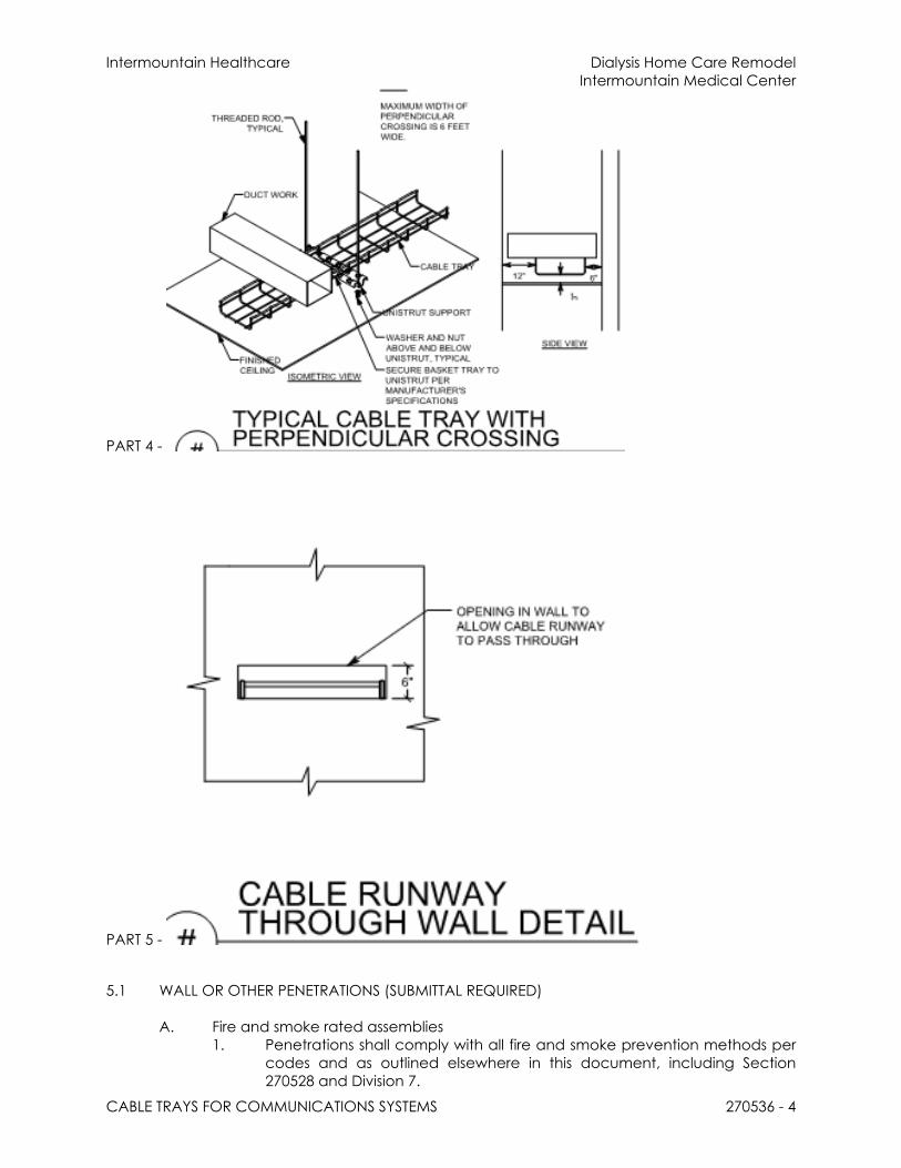
Intermountain Healthcare Dialysis Home Care RemodelIntermountain Medical Center
CABLE TRAYS FOR COMMUNICATIONS SYSTEMS 270536 - 4
PART 4 -
PART 5 -
5.1 WALL OR OTHER PENETRATIONS (SUBMITTAL REQUIRED)
A. Fire and smoke rated assemblies1. Penetrations shall comply with all fire and smoke prevention methods per
codes and as outlined elsewhere in this document, including Section 270528 and Division 7.
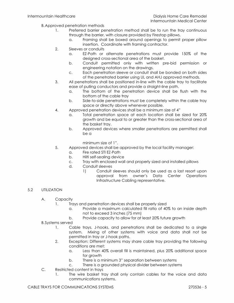
Intermountain Healthcare Dialysis Home Care RemodelIntermountain Medical Center
CABLE TRAYS FOR COMMUNICATIONS SYSTEMS 270536 - 5
B.Approved penetration methods1. Preferred barrier penetration method shall be to run the tray continuous
through the barrier, with closure provided by Firestop pillows.a. Framing shall be boxed around openings to permit proper pillow
insertion. Coordinate with framing contractor. 2. Sleeves or conduits
a. EZ-Path or alternate penetrations must provide 150% of the designed cross-sectional area of the basket.
b. Conduit permitted only with written pre-bid permission or engineering notation on the drawings.
c. Each penetration sleeve or conduit shall be bonded on both sides of the penetrated barrier using UL and AHJ approved methods.
3. All penetrations shall be positioned in-line with the cable tray to facilitate ease of pulling conductors and provide a straight-line path. a. The bottom of the penetration device shall be flush with the
bottom of the cable trayb. Side-to-side penetrations must be completely within the cable tray
space or directly above whenever possible.4. Approved penetration devices shall be a minimum size of 4”
a. Total penetration space at each location shall be sized for 20% growth and be equal to or greater than the cross-sectional area of the basket tray.
b. Approved devices where smaller penetrations are permitted shall be a
minimum size of 1”.5. Approved devices shall be approved by the local facility manager:
a. Fire rated STI EZ-Pathb. Hilti self-sealing devicec. Tray with enclosed wall and properly sized and installed pillowsd. Conduit sleeves
1) Conduit sleeves should only be used as a last resort upon approval from owner’s Data Center Operations Infrastructure Cabling representative.
5.2 UTILIZATION
A. Capacity1. Trays and penetration devices shall be properly sized
a. Provide a maximum calculated fill ratio of 40% to an inside depth not to exceed 3 inches (75 mm)
b. Provide capacity to allow for at least 20% future growthB.Systems served
1. Cable trays, J-hooks, and penetrations shall be dedicated to a single system. Mixing of other systems with voice and data shall not be permitted in tray or J-hook paths.
2. Exception: Different systems may share cable tray providing the following conditions are met:a. Less than 40% overall fill is maintained, plus 20% additional space
for growthb. There is a minimum 3” separation between systemsc. There is a grounded physical divider between systems
C. Restricted content in trays1. The wire basket tray shall only contain cables for the voice and data
communications systems.

Intermountain Healthcare Dialysis Home Care RemodelIntermountain Medical Center
CABLE TRAYS FOR COMMUNICATIONS SYSTEMS 270536 - 6
a. If there is sufficient space in the tray, and with approval from both the data network sub-contractor and the Data Center Operations, certain other IP services may share tray space. (i.e. camera, telemetry, similar).
b. Service loops must not reduce tray capacity.c. Nurse call cabling shall be run in the J-Hook path. All nurse call
installations must provide their own path or utilize the triple J-Hook system.
D. Triple J-Hook path assignments1. The Lower tier of the triple J-Hook path is designated for Card Access and
building automation and controls2. The Middle tier of the triple J-Hook path may alternately be utilized for
Nurse Call, or other EMI producing systems.3. The Top tier of the triple J-Hook path is designated for satellite, DAS, or
similar systems.4. When a triple J-hook pathway is not installed or available each system
provider shall install their own j-hook pathway and wall penetrations.5. Service loop and slack shall not interfere with other pathways.
END OF SECTION

Intermountain Healthcare Dialysis Home Care RemodelIntermountain Medical Center
IDENTIFICATION FOR ELECTRICAL SYSTEMS 270543 - 1
SECTION 270543/46 - UNDERGROUND DUCTS, UTILITY POLES, AND RACEWAYS FOR INTER-BUILDING/CAMPUS CABLE ROUTING
PART 1 - PRODUCTS
1.1 INTER-BUILDING/CAMPUS CABLE ROUTINGA. The backbone subsystem shall include cable installed between buildings via
approved underground, tunnel, direct -buried, aerial or any combination of these from the Campus Distributor/Main Cross-connect (CD/MC/TEC) to Building Distributor/Intermediate Cross-connect (BD/IC/TDR) in a multi-building campus.1. 4” Conduit is required 2. (3) 1 ¼” inner ducts shall be installed in all 4” conduits going building to
building.3. Armored Fiber is required.4. Microduct/microfiber is optional.
B.Backbone pathways shall be installed or selected such that the minimum bend radius and pulling tension of backbone cables is kept within cable manufacturer specifications both during and after installation.
C. In an underground system, adequate underground conduit space shall be available and accessible at each building. The conduits shall not exceed a fill ratio of 40%. 1. All underground systems shall be designed to prevent water runoff from
entering the building. All underground systems must be cleared of any moisture prior to installation of any cable type. These systems must be sealed at both ends when not in use and after cable installation to prevent moisture and rodent infiltration.
PART 2 - EXECUTION
2.1 INSTALLATIONA. The backbone cables shall be installed in a hierarchical star topology, emanating
from the Campus Distributor/Main Cross-connect to each satellite building, Building Distributor/Intermediate Cross-connect or Floor Distributor/Horizontal Cross-connect located in a telecommunication room. All Inter-building/Campus cables shall be installed to the applicable codes and regulations.
B.Where redundant paths are required, they shall be separated by a minimum of 24”.1. Separate innerducts are required for each leg of the redundant path.2. Separate physical routing for each path shall be utilized where possible.
C. Optical fiber shall be run for all Inter-building/Campus backbone segments, and as a recommendation, at least one balanced twisted-pair cable should be run for each Inter-building backbone segment.1. Fibers will be Fusion Spliced in the telecommunications rooms using LC
Pigtails in wall mounted interconnect centers or rack mounted panels equipped with sufficient ports, slack storage space and splice trays if required to terminate and secure all fibers.
D. ST connectors are no longer recommended in the TIA 568-C.3 standard but may be used in legacy installations.
E.Over-voltage Circuit Protection shall be utilized for cabling which enters or exits a building shall comply with applicable codes and regulations.
F. OSP (outside plant) cables shall transition to an ISP (inside plant) within 50 feet of changing environment, per national and local codes and regulations.
END OF SECTION

Intermountain Healthcare Dialysis Home Care RemodelIntermountain Medical Center
IDENTIFICATION FOR LOW-VOLTAGE CABLES AND LABELING 270553 - 1
SECTION 270553 - IDENTIFICATION FOR LOW-VOLTAGE CABLES AND LABELING
PART 1 - GENERAL
1.1 NOT USED
PART 2 - PRODUCTS
2.1 LABELING
A. Structured cabling shall be labeled in accordance with ANSI/TIA 606-B standards.B.A unique identifier shall be marked on each faceplate to identify it as connecting
hardware.C. Each port in the faceplate shall be labeled with its identifier.D. A unique identifier shall be marked on each piece of connecting hardware to
identify it as connecting hardware.E.Each port on the connecting hardware shall be labeled with its identifier.F. Cable Labeling
1. Label Systema. Labels Identification (Labeling) System:
1) Brady2) Dymo3) Hellerman-Tyton4) Panduit5) Acceptable alternate
a) Approval from Data Center Operations Infrastructure Cabling team member required prior to bid
2. Cable Labelsa. Self-adhesive vinyl or vinyl-cloth wraparound tape markers,
machine printed with alphanumeric cable designations. Plastic, self-adhesive labels are not acceptable.
b. Each end of the Horizontal cables shall be labeled with a mechanically generated label within 300mm (12 in) of the end of the cable jacket with the link identifier which shall be a unique configuration determined by owner. This also applies to the Backbone Cables.
3. Flat-surface labelsa. Self-adhesive vinyl or vinyl-cloth labels, machine printed with
alphanumeric cable designations4. Contractor shall:
a. Provide transparent plastic label holders, and 4 pair marked colored labels.
b. Install colored labels according to the type of field as per ANSI/TIA 606-B.1 color code designations.
G. PALLETTE1. Use the owners color-code guidelines for voice, data, cross-connect, riser,
and backbone fields. Otherwise, use the ANSI/TIA 606-B designation strip color-code guidelines for voice, data, cross-connect, riser, and backbone fields. Color designations for F/UTP cable:a. Intermountain Healthcare Standard Wiring Palettes for Horizontal
Cablingb. Use Color
1) Data & IP Phones Blue2) Analog Phone Blue

Intermountain Healthcare Dialysis Home Care RemodelIntermountain Medical Center
IDENTIFICATION FOR LOW-VOLTAGE CABLES AND LABELING 270553 - 2
3) Security Card Readers Grey/Yellow4) IP Security Cameras Blue5) Fire Systems Red6) TV Coax Black7) Public Address/Telecom Patching in TEC only White8) Clinical Engineering – Orange
a) Monitoring, Bed Systems Orangeb) Nurse Call (5e) Orangec) Real time patient data Orange
9) Wireless Yellow10) Foreseer (Belden 1422) Red
H. Outlet/Jack/Faceplate Icons/labeling will match the color of the cable attached to the back side of the outlet/jack.
PART 3 - EXECUTION
3.1 GENERAL IDENTIFICATION
A. Installer shall label all cable, regardless of length.B.Identify system components, wiring, and cabling complying with TIA/EIA-606-B.1.
Comply with requirements for identification specified in Division 26 Section "Identification for Electrical Systems."
C. Color-code cross-connect fields. Apply colors to voice and data service backboards, connections, covers, and labels.
D. Using cable management system software specified in Part 2, develop Cabling Administration Drawings for system identification, testing, and management. Use unique, alphanumeric designation for each cable and label cable, jacks, connectors, and terminals to which it connects with same designation. At completion, cable and asset management software shall reflect as-built conditions.
E.Cable Schedule: Post in prominent location in each equipment room and wiring closet. List incoming and outgoing cables and their designations, origins, and destinations. Protect with rigid frame and clear plastic cover. Furnish an electronic copy of final comprehensive schedules for Project.
F. Cabling Administration Drawings: Show building floor plans with cabling administration-point labeling. Identify labeling convention and show labels for telecommunications rooms, backbone pathways and cables, entrance pathways and cables, terminal hardware and positions, horizontal cables, work areas and workstation terminal positions, grounding buses and pathways, and equipment grounding conductors. Follow convention of TIA/EIA-606-B.1. Furnish electronic record of all drawings, in software and format selected by Owner
3.2 CONCEALED ENDS
A. Jacks, connectors, terminations, and similar that are in concealed locations such as above grid ceilings, shall have additional labeling. The additional label shall be on the face of the grid in a visible location, immediately adjacent to the termination location.
3.3 CABLE AND WIRE IDENTIFICATION
A. Label each cable visibly within 4 inches of each termination and tap, where it is accessible in a cabinet or junction or outlet box, and elsewhere as indicated.
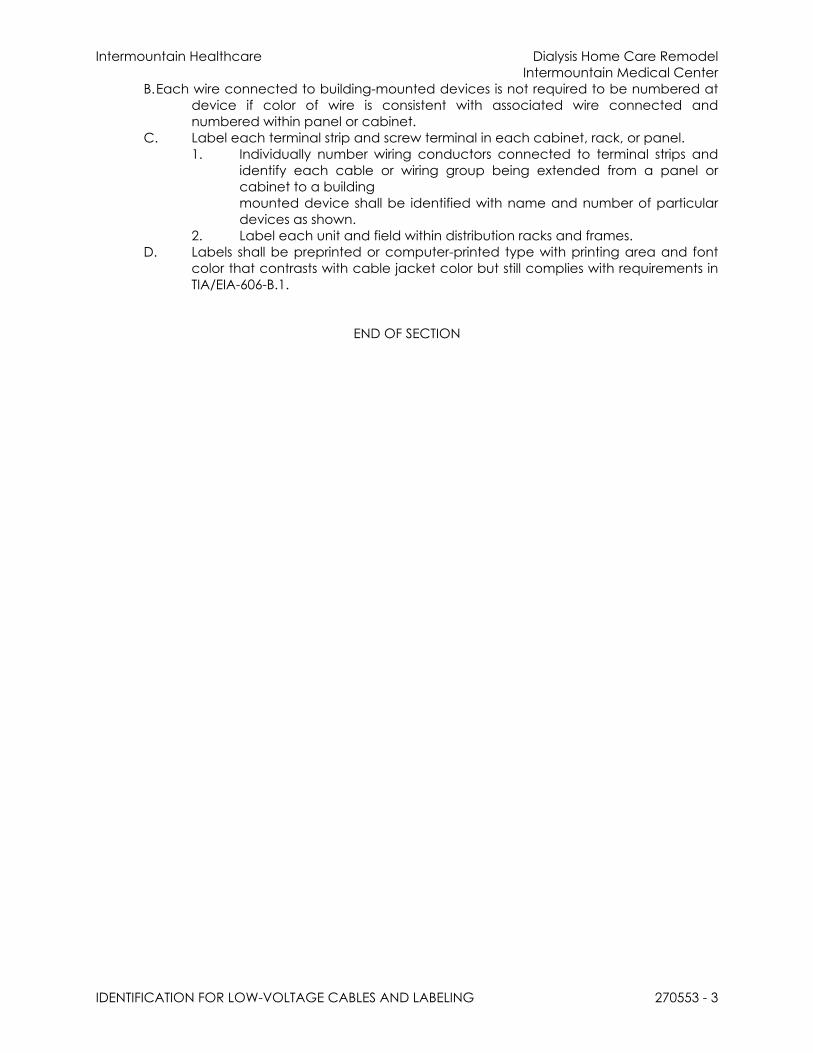
Intermountain Healthcare Dialysis Home Care RemodelIntermountain Medical Center
IDENTIFICATION FOR LOW-VOLTAGE CABLES AND LABELING 270553 - 3
B.Each wire connected to building-mounted devices is not required to be numbered at device if color of wire is consistent with associated wire connected and numbered within panel or cabinet.
C. Label each terminal strip and screw terminal in each cabinet, rack, or panel.1. Individually number wiring conductors connected to terminal strips and
identify each cable or wiring group being extended from a panel or cabinet to a building mounted device shall be identified with name and number of particular devices as shown.
2. Label each unit and field within distribution racks and frames.D. Labels shall be preprinted or computer-printed type with printing area and font
color that contrasts with cable jacket color but still complies with requirements in TIA/EIA-606-B.1.
END OF SECTION

Intermountain Healthcare Dialysis Home Care RemodelIntermountain Medical Center
TERMINATION BLOCKS AND PATCH PANELS 271119 - 1
SECTION 271119 - TERMINATION BLOCKS AND PATCH PANELS
PART 1 - GENERAL
1.1 RELATED DOCUMENTS
A. Requirements of the following Division 26 sections apply to this section1. Basic electrical requirements2. Basic electrical materials and methods3. Grounding, Earthing, and Bonding
PART 2 - PRODUCTS
2.1 APPROVED PRODUCT
A. PATCH PANELS – COPPER1. 48 Port CAT 6A Shielded, 1RU Angled Patch Panel with Outlets –
Siemon Z6AS-PA-48A2. 48 Port CAT 6A Shielded, 1RU Flat Patch Panel with Outlets –
Siemon Z6AS-PNL-U48K3. 24 Port CAT 6A Shielded, 1RU Plat Patch Panel with Outlets –
Siemon Z6AS-PNL-U24K4. 48 Port CAT 5e, 2RU Angled Patch Panel, 110 Style – Siemon HD5-48A5. 48 Port CAT 5e, 2RU Flat Patch Panel, 110 Style – Siemon HD5-486. 24 Port CAT 5e, 1RU Angled Patch Panel, 110 Style – Siemon HD5-24A7. 24 Port CAT 5e, 1RU Flat Patch Panel, 110 Style – Siemon HD5-248. 19” Angled Blank Filler Panel, 1U, Black – Siemon PNL-BLNKA-1
a. Provide blank fillers where appropriate.9. 19” Flat Blank Filler Panel, 1U, Black – Siemon PNL-BLNK-1
a. Provide blank fillers where appropriate.B. PATCH PANELS – FIBER
1. Rack Mount Fiber Enclosure – Siemon RIC3-48E-012. Wall Mount Fiber Enclosure – Siemon SWIC3G-AA-013. Blank Adapter Plate, Black – Siemon RIC-F-BLANK-014. 12F-LCUPC-SM-Loaded–Splice Cassette - Siemon – RSC12-LCUSMA-B1
C. CABINET PATCH PANEL – FIBER1. Lightstack Surface Mount Module Enclosure – Siemon – LSE-012. Lightstack Surface Mount Splice Enclosure – Siemon – LSS-013. LightStack LC Adapter Plate – Siemon LS-LS12-01C-AQ
PART 3 - EXECUTION
3.1 INSTALLATION
A. For angled patch panels, the terminations shall cross in the back to the opposite path of the patch panel to maximize available cable bend radius.
B.See illustration below in this section:

Intermountain Healthcare Dialysis Home Care RemodelIntermountain Medical Center
TERMINATION BLOCKS AND PATCH PANELS 271119 - 2
END OF SECTION

Intermountain Healthcare Dialysis Home Care RemodelIntermountain Medical Center
HORIZONTAL CABLING 271500 - 1
SECTION 271500 - HORIZONTAL CABLING
PART 1 - GENERAL
1.1 RELATED DOCUMENTS
A. Drawings and general provisions of the Contract, including General and Supplementary Conditions and Division 01 Specification Sections, apply to this section.
B. Section 27 05 28 - Pathways for Communications Systems
1.2 SUMMARY
A. This section includes requirements and guidelines for the installation of F/UTP, ScTP, and Fiber horizontal cabling. 1. Horizontal cable and its connecting hardware provide the means of
transporting signal between the telecommunications outlet/connector and the horizontal cross-connect located in the communications termination room This cabling and its connecting hardware are called "permanent link," a term that is used in the testing protocols.
PART 2 - EXECUTION
2.1 HORIZONTAL CABLE
A. Quantity1. Two horizontal cables shall be routed to each work area. Cable
connected to information outlets shall be CAT6A F/UTP, 4-pair, 100Ω balanced twisted-pair.a. A work area is approximately 100 sq. ft. and includes the
components that extend from the telecommunications outlet/connectors to the station equipment.
b. Two (2) standard cables shall be run to each wireless access point location per current best practice.
c. One (1) standard horizontal cable may be run to the following locations:1) Each building control system enclosure as directed by the
building controls vendor. 2) Each IP Video Surveillance Camera at each of the
designated locations.3) Each wall phone.4) Each wall monitor/display.
2. For voice or data applications, 4-pair balanced twisted-pair or fiber optic cables shall be run using a star topology from the telecommunications room serving that floor to every individual information outlet. The customer prior to installation of the cabling shall approve all cable routes.
3. Installation interfaces shall be T568B wiring standards.B. Maximum Length
1. All horizontal cables, regardless of media type, shall not exceed 90 m (295 ft.) from the telecommunications outlets in the work area to the Floor
2. Distributor/Horizontal Cross connect (FD/HC) located in the Telecommunication Room.

Intermountain Healthcare Dialysis Home Care RemodelIntermountain Medical Center
HORIZONTAL CABLING 271500 - 2
3. The combined length of jumpers, patch cords inclusive of equipment cables in the Floor Distributor/Horizontal Cross-connect shall not exceed 5m (16 ft.).
4. The maximum length of Work Area equipment cables shall be 5m (16 ft.) If a MuTOA (Multiple User Telecommunication Outlet) environment exists, then the maximum equipment cable shall not exceed 22m (72 ft.) (Lake Park Facility)
5. Terminate all conductors; no cable shall contain un-terminated elements. Make terminations only at indicated outlets, terminals, cross-connects, and patch panels.
C. Minimum Length1. It is recommended that a minimum horizontal cable distance of 15m (49
ft.) shall be maintained between the telecommunications room and the work area. This will provide adequate Insertion Loss/Attenuation for applications over 1 Gig.
2. For installations with consolidation points, a minimum horizontal cable distance of 15m (49 ft.) shall be maintained between the telecommunications room and consolidation point, and 5m (16 ft.) between the consolidation point and the work area. This will provide adequate Insertion Loss/Attenuation for applications over 1 Gig.
D. Splice Free1. Each run of balanced twisted-pair cable between Floor
Distributor/Horizontal Cross-connect in the telecommunication room and the information outlet at the Work Area shall not contain splices.
2. Bridged taps and splices shall not be installed in the horizontal cablingE. Protection
1. Horizontal distribution cables shall not be run in under slab raceways that are damp or wet locations unless suitably rated for the environment.a. Under slab conduits that are outside of the building are
considered wet locations.F. Slack -Service Loop – Routing
1. In the work area, a minimum of 1m (3 ft) should be left for balanced twisted-pair cables and fiber cables.
2. In telecommunications rooms a minimum of 3m (10 ft) of slack should be left for all cable types. This slack must be neatly managed on trays or other support types
2.2 SEPARATION
A. Separation from EMI sources1. Installation shall comply with BICSI TDMM and TIA/EIA-569-B for separating
unshielded copper voice and data communication cable from potential EMI sources, including electrical power lines and equipment.
2. Separation between open communications cables or cables in nonmetallic raceways and unshielded power conductors and EMI Source shall be as follows:a. EMI Source Rating Less Than 2 kVA: A minimum clearance of 5
inches.b. EMI Source Rating between 2 and 5 kVA: A minimum clearance of
12 inches.c. EMI Source Rating More Than 5 kVA: A minimum clearance of 24
inches.

Intermountain Healthcare Dialysis Home Care RemodelIntermountain Medical Center
HORIZONTAL CABLING 271500 - 3
3. Separation between communications cables in grounded metallic raceways and unshielded power lines or EMI Source shall be as follows:a. EMI Source Rating Less Than 2 kVA: A minimum clearance of 2-1/2
inches.b. EMI Source Rating between 2 and 5 kVA: A minimum clearance of
6 inches.c. EMI Source Rating More Than 5 kVA: A minimum clearance of 12
inches.4. Separation between communications cables in grounded metallic
raceways and power lines and EMI Source located in grounded metallic conduits or enclosures shall be as follows:a. EMI Source Rating Less Than 2 kVA: A minimum clearance of 2
inches.b. EMI Source Rating between 2 and 5 kVA: A minimum clearance of
3 inches.
c. EMI Source Rating More Than 5 kVA: A minimum clearance of 6 inches.
5. Separation between Communications Cables and Electrical Motors and Transformers, 5 kVA or 1 HP and Larger: A minimum clearance of 48 inches.
6. Separation between Communications Cables and Fluorescent Fixtures: A minimum clearance of 5 inches
B. Other Clearances 1. Horizontal pathways used for telecommunications cabling shall be
dedicated for telecommunications use and not shared by other building services.
2. In a false ceiling environment, a minimum of 75 mm (3 in) shall be observed between the cable supports and the false ceiling.
2.3 PATHWAY
A. Cable Tie Wraps1. Cable Tie Wraps are not permitted as a pathway device or support.2. Tie Wraps shall only be used to provide strain relief at termination points.3. Tie wraps shall not be over tightened to the point of deforming or crimping
the cable sheath.B. Constraints
1. Horizontal cables shall be installed in “dry” locations that provide protection from moisture levels above the intended operating range of inside plant (ISP) cables. a. If cabling is intentionally or unintentionally exposed to water or
otherwise coated with or exposed to direct contact with solvents, paints, adhesives, sealants or other third-party materials, Siemon will not warranty the cabling product or if after the warranty has been issued, it would become void. Therefore, any cabling that has been exposed as listed above, must be removed and replaced.
2. Horizontal pathways shall be installed or selected such that the minimum bend radius of horizontal cables is kept within manufacturer specifications both during and after installation.
3. A minimum of a 1” diameter conduit is recommended for new construction. Existing conduits will require the reduction of the number of cables placed in the conduit to meet the required fill ratio.

Intermountain Healthcare Dialysis Home Care RemodelIntermountain Medical Center
HORIZONTAL CABLING 271500 - 4
a. The Contractor shall observe the bending radius and pulling strength requirements of the 4-pair balanced twisted-pair and fiber optic cable during handling and installation.1) 4-Pair UTP, F/UTP, S/FTP bend radius = 4 times outside
diameter of cable under no-load conditions. 8 times the outside diameter under load (pulling 110 N/25 lbf.) conditions.
2) Multi-pair or Hybrid cable bend radius = 10 times the outside diameter under all conditions.
3) 2-Fiber and 4 Fiber cables bend radius = 25mm (1 in.) under no-load conditions. 50mm (2 in.) under load (pulling 222 N 50 lbf)
4. Cable shall not be run through structural members or in contact with pipes, ducts, or other potentially damaging items.
5. Cable that passes through non-Intermountain Healthcare spaces must be installed in conduit.
6. Horizontal cabling shall contain no more than one transition point or consolidation point between the horizontal cross-connect and the telecommunications outlet/connector.
7. Do not install bruised, kinked, scored, deformed, abraded cable or otherwise damaged cable. Do not splice cable between termination, tap, or junction points. Remove and discard cable if damaged during installation and replace it with new cable.
8. During Cold-Weather Installation, bring cable to room temperature before de-reeling. Heat lamps shall not be used for heating.
C. Capacity
1. The number of horizontal cables placed in a cable support or pathway shall be limited to the number of cables that will not alter the geometric shape of the cables.
2. Maximum pathway (cable tray/basket tray/wireway) capacity shall not exceed a calculated fill ratio of 50% to a maximum of 75 mm (3 in) inside depth.
3. Maximum conduit pathway capacity shall not exceed a 40% fill. However, perimeter and furniture fill are limited to 60% fill for move and changes. A 40% fill ratio is the maximum fill for CAT6A F/UTP cables.
4. All unused cables shall be removeda. Or labeled at both ends designating future purpose and locations
of each end.
END OF SECTION
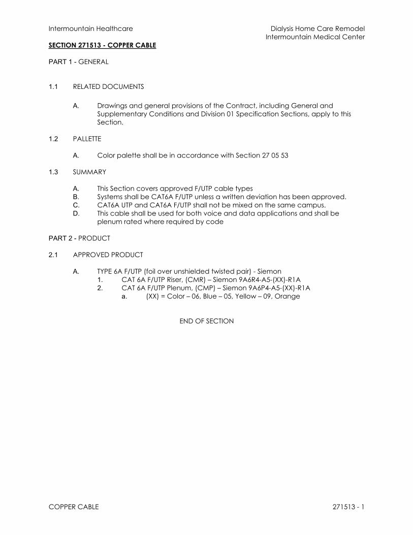
Intermountain Healthcare Dialysis Home Care RemodelIntermountain Medical Center
COPPER CABLE 271513 - 1
SECTION 271513 - COPPER CABLE
PART 1 - GENERAL
1.1 RELATED DOCUMENTS
A. Drawings and general provisions of the Contract, including General and Supplementary Conditions and Division 01 Specification Sections, apply to this Section.
1.2 PALLETTE
A. Color palette shall be in accordance with Section 27 05 53
1.3 SUMMARY
A. This Section covers approved F/UTP cable typesB. Systems shall be CAT6A F/UTP unless a written deviation has been approved.C. CAT6A UTP and CAT6A F/UTP shall not be mixed on the same campus.D. This cable shall be used for both voice and data applications and shall be
plenum rated where required by code
PART 2 - PRODUCT
2.1 APPROVED PRODUCT
A. TYPE 6A F/UTP (foil over unshielded twisted pair) - Siemon1. CAT 6A F/UTP Riser, (CMR) – Siemon 9A6R4-A5-(XX)-R1A2. CAT 6A F/UTP Plenum, (CMP) – Siemon 9A6P4-A5-(XX)-R1A
a. (XX) = Color – 06, Blue – 05, Yellow – 09, Orange
END OF SECTION

Intermountain Healthcare Dialysis Home Care RemodelIntermountain Medical Center
FACEPLATES AND CONNECTORS 271543 - 1
SECTION 271543 - FACEPLATES AND CONNECTORS
PART 1 - GENERAL
1.1 RELATED DOCUMENTS
A. Drawings and general provisions of the Contract, including General and Supplementary Conditions and Division 01 Specification Sections, apply to this Section.
1.2 DEFINITION
A. Work-Area Cabling1. The work area is comprised of work area outlet/connectors, faceplates,
outlet boxes and equipment cords. It acts as the interface to the horizontal cabling from the horizontal cross-connect (HC) to telephone, network equipment, wireless access points (WAP) and OIP devices.
PART 2 - PRODUCT
2.1 OUTLETS
A. Category 6A Jack – Siemon Z6A-S(XX)1. Use (XX) to specify color.2. Universal design allows the same outlet to be mounted in a flat or angled
orientation. B. Category 6A Z-Plug WO Latch Protector – Siemon ZP1-6AS-(00)SC. Voice Outlet, Single Gang Faceplate, White W/Wall Hung Phone W/6A Insert –
Siemon MX-WP-Z6AS-SS
2.2 FACEPLATES/BOXES
A. 10G Single Gang Faceplate, White, 4 Position – Siemon 10GMX-FP-04-02B. MAX Single Gang Faceplate, White – Siemon MX-FP-S-(XX)-02
1. USE (XX) to specify the number of ports.C. MAX Single Gang Faceplate, Stainless Steel, 4 Position, with Label Holder – Siemon
MX-FP-S-04-SS-L1. To be used in the Operation Rooms
D. Surface Mount Box, White, 2 Position – Siemon MX-SMZ2-02E. Furniture Faceplate, Black – Siemon MX-UMA-01F. Conference Room Table Inserts should include and HDMI port.
PART 3 - EXECUTION
3.1 WORK AREA TERMINATION
A. All balanced twisted-pair cables wired to the telecommunications outlet/connector, shall have 4-pairs terminated in eight-position modular outlets in the work area. All pairs shall be terminated.
B. Outlet/connector back boxes shall be a minimum 4-11/16 square box (4-11/16” x 4-11/16” x 3”) with a minimum single gang 5/8” mud ring for new construction to accommodate the CAT6A connectors.

Intermountain Healthcare Dialysis Home Care RemodelIntermountain Medical Center
FACEPLATES AND CONNECTORS 271543 - 2
C. Existing back boxes will require a faceplate stand-off and/or a faceplate that can accommodate a bezel to extend the CAT6A jack out to allow the installation of the CAT6A connectors.
D. All outlets need to be installed in the angled position.
END OF SECTION

Intermountain Healthcare Dialysis Home Care RemodelIntermountain Medical Center
PATCH PANELS 271619 - 1
SECTION 271619 - PATCH CABLES
PART 1 - GENERAL
1.1 SUMMARY
A. This section is issued as a guide for patch cable installations in the Data Center, wiring closets (TDR) and user areas where patch cables are required for connectivity to IP and TDM phones, and IP data connectivity needs for Intermountain Healthcare. All patch cables will support voice, data, and imaging applications within the Intermountain Healthcare Enterprise.
PART 2 - PRODUCTS
2.1 APPROVED PRODUCT
A. Patch Cable, CAT 6A Shielded - Siemon SP6A-S (XX)-(XX) 1. Use 1st (xx) to specify length. Use 2nd (xx) for color.
B.Patch Cable, CAT 5e, Orange – Siemon MC5-(XX)-09091. Use (xx) to specify length. For use with NURSE CALL only.
C. Patch Cable, CAT 5e, White – Siemon MC5-(XX)-02021. Use (xx) to specify length. 2. For use in the TEC for the Copper Backbone Patch only.
D. Patch Cable, Fiber, Singlemode Duplex W/LC Connectors, Yellow – Siemon FJ2-LCULCUL-(xx)1. Use (xx) to specify length.
E.Patch Cable, Fiber, Multimode Duplex W/LC Connectors, Aqua – Siemon FJ2-LCLC5V-(xx)AQ1. Use (xx) to specify length. For use in the Data Center.
PART 3 - EXECUTION
3.1 PALLETTE
A. Patch Cable Color Codes1. The Intermountain Healthcare Enterprise standard for patch cable color is
in Section 27 05 53.2. The patch cable color shall match the feed cable color to identify the
service provided.B.Contractor furnished
1. All patch cables for the TEC, TDR’s shall be included in the low voltage contract and will be required to match or exceed the existing level of the installed structured cabling system.
2. All patch cables for the user areas shall be Owner furnished and will be required to match or exceed the existing level of the installed structured cabling system.
3. All patch cables shall be Owner installed.4. The quantity of patch cables to be provided by the low voltage
contractor shall be specified in the plans.a. 50% 5ft – 30% 7ft – 15% 10ft – 5% 15ft
END OF SECTION
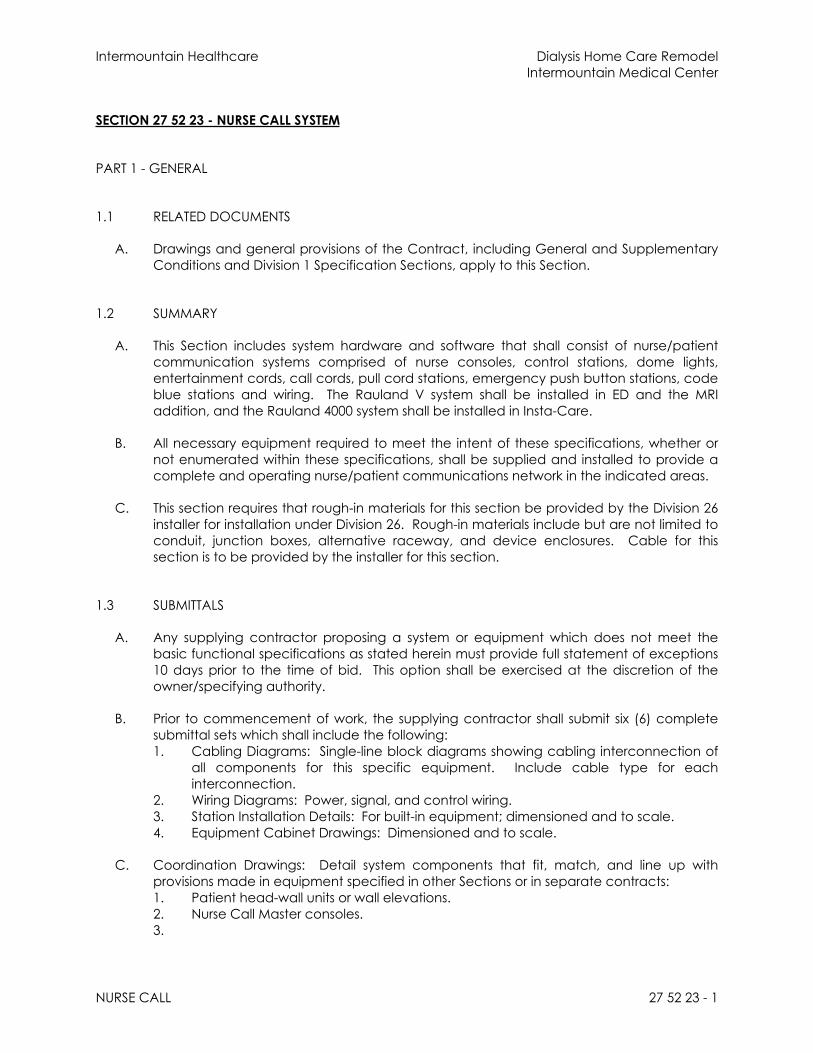
Intermountain Healthcare Dialysis Home Care RemodelIntermountain Medical Center
NURSE CALL 27 52 23 - 1
SECTION 27 52 23 - NURSE CALL SYSTEM
PART 1 - GENERAL
1.1 RELATED DOCUMENTS
A. Drawings and general provisions of the Contract, including General and Supplementary Conditions and Division 1 Specification Sections, apply to this Section.
1.2 SUMMARY
A. This Section includes system hardware and software that shall consist of nurse/patient communication systems comprised of nurse consoles, control stations, dome lights, entertainment cords, call cords, pull cord stations, emergency push button stations, code blue stations and wiring. The Rauland V system shall be installed in ED and the MRI addition, and the Rauland 4000 system shall be installed in Insta-Care.
B. All necessary equipment required to meet the intent of these specifications, whether or not enumerated within these specifications, shall be supplied and installed to provide a complete and operating nurse/patient communications network in the indicated areas.
C. This section requires that rough-in materials for this section be provided by the Division 26 installer for installation under Division 26. Rough-in materials include but are not limited to conduit, junction boxes, alternative raceway, and device enclosures. Cable for this section is to be provided by the installer for this section.
1.3 SUBMITTALS
A. Any supplying contractor proposing a system or equipment which does not meet the basic functional specifications as stated herein must provide full statement of exceptions 10 days prior to the time of bid. This option shall be exercised at the discretion of the owner/specifying authority.
B. Prior to commencement of work, the supplying contractor shall submit six (6) complete submittal sets which shall include the following:1. Cabling Diagrams: Single-line block diagrams showing cabling interconnection of
all components for this specific equipment. Include cable type for each interconnection.
2. Wiring Diagrams: Power, signal, and control wiring.3. Station Installation Details: For built-in equipment; dimensioned and to scale.4. Equipment Cabinet Drawings: Dimensioned and to scale.
C. Coordination Drawings: Detail system components that fit, match, and line up with provisions made in equipment specified in other Sections or in separate contracts:1. Patient head-wall units or wall elevations.2. Nurse Call Master consoles.3.

Intermountain Healthcare Dialysis Home Care RemodelIntermountain Medical Center
NURSE CALL 27 52 23 - 2
D. Manufacturer Certificates: Signed by manufacturers certifying that nurse call equipment complies with requirements.
E. Field Tests Reports and Observations: Include record of final adjustments certified by Installer.
F. Operation and Maintenance Data: For nurse call equipment to include in emergency, operation, and maintenance manuals. In addition to items specified in Division 1 "Closeout Procedures “ and “Operation and Maintenance Data," include the following:1. Operating instructions.2. Troubleshooting guide.3. Wiring diagrams and terminal identification.4. Equipment parts list.5. Product data for types and sizes of wires and cables used.
G. Warranty Statement: Special warranty requirements as specified in this Section.
1.4 QUALITY ASSURANCE
A. Installer Qualifications: Manufacturer's authorized representative who is trained and approved for installation of units required for this Project. The Installer shall be able to fully support the listed service and warranty requirements as specified herein.
B. Manufacturer Qualifications: A firm experienced in manufacturing equipment similar to that indicated for this Project and that maintains technical support services capable of providing user with training, parts, and emergency maintenance and repair with a 24-hour-maximum response time.
C. Source Limitations: Obtain nurse call equipment components through one source from a single manufacturer.
D. Electrical Components, Devices, and Accessories: Listed and labeled according to UL 1069 as defined in NFPA 70, Article 100, by a testing agency acceptable to authorities having jurisdiction, and marked for intended use.
1.5 COORDINATION
A. Coordinate patient control units with items controlled that are not part of nurse call equipment.1. TV: Channel selection and volume.
B. Coordinate wiring paths and maintenance access at locations listed below. Coordinate trim features and finishes at these locations to present a unified design appearance.1. Patient head-wall installations.2. Patient consoles.3. Nurse station.

Intermountain Healthcare Dialysis Home Care RemodelIntermountain Medical Center
NURSE CALL 27 52 23 - 3
1.6 WARRANTY
A. The installing contractor shall provide a warranty on the system which shall include all necessary labor and equipment to maintain the system(s) in full operation for a period of one year from the date of acceptance.
B. Manufacturer shall provide, free of charge, product firmware/software upgrades throughout the warranty period for any product feature enhancements.1.
PART 2 - PRODUCTS
2.1 MANUFACTURERS
A. Manufacturers: Subject to compliance with requirements, provide products by one of the following:
1. Rauland-Borg Corporation (Connect to existing Rauland 5 system)
2.2 SYSTEM REQUIREMENTS
A. Coordinate the features of materials and equipment to form an integrated system. Match components and interconnections for optimum performance of specified functions. System shall be microprocessor based, but independent of the facility’s local area network, with a segmented platform configuration providing that system or equipment failures are locally mitigated without global system shutdowns or resets.
B. Expansion Capability: Equipment ratings, housing volume, spare keys, switches, relays, annunciator modules, terminals, and cable conductor quantities adequate to increase the number of stations in the future by 20 percent above those indicated without adding internal or external components or main trunk cable conductors.
C. Resistance to Electrostatic Discharge: System, components, and cabling, and the selection, arrangement, and connection of materials and circuits, shall be protected against damage or diminished performance when subjected to electrostatic discharges of up to 25,000 V in an environment with a relative humidity of 20 percent or less.
D. Equipment: Solid state, modular.
E. Wall-Mounted Component Connection Method: Components connect to system wiring in back boxes with factory-wired plug connectors.
2.3 FUNCTIONAL PERFORMANCE
A. Station Selection: Master station is capable of selectively communicating with other stations or groups of stations on its system by operating selector switches.

Intermountain Healthcare Dialysis Home Care RemodelIntermountain Medical Center
NURSE CALL 27 52 23 - 4
B. Master Station Privacy: Capable of conversing with individual stations in complete privacy.
C. Hands Free: Called station is capable of conversing hands free.
D. Annunciation: At the master station, a tone announces an incoming call and a visual indication is displayed on the console and identifies the calling station and indicates the priority of the call. LED/LCD lighted displays or touchscreens identify stations selected for outgoing calls.
E. System Reset at Master Station: When a normal incoming call is canceled, associated lights and audible tones are extinguished, and the system is reset when the station switch is returned to the normal position after responding to a call.
F. Patient Station Call: Activates the call-placed lamp at patient station, zone, and corridor dome lights. It sounds a tone and lights the call lights at staff/duty stations and actuates annunciation at the master station. When the calling station is selected at the master station, the patient can converse with the master station without moving and without raising or directing the voice. During voice communications, entertainment audio at the calling station is automatically muted.
G. Pull-Cord Call Station and Emergency-Call Station Call: Activates call-placed lamp and corridor dome light, and flashes zone light. Master station tone pulses with visual display for that room flashes. When master station acknowledges the call, the tone stops but the display and lights continue to function until the call is canceled at the point of origin.
H. Code Blue Station Call: Activates the call-placed lamp at the station and actuates annunciation at the master station. When the called station is selected at the master station, the tone stops but the display and lights continue to function until the call is canceled at the point of origin. 1. Code Blue: Unique sound and light pattern, indicating the highest priority
emergency.
I. Handset Operation: Lifting handset on master station disconnects speaker microphone and transfers conversation to the handset.
J. Station Privacy: No patient, staff, or duty station can be remotely monitored without the lighting of a warning lamp at the monitored station.
K. Patient Station Cord Set: When a patient station cord-set plug is removed from the jack in the station faceplate, a patient station call is initiated as described above. When the master station call button for the station is pressed, the tone stops but lights continue to flash until the call is canceled at the point of origin or the plug is reinserted or replaced with a dummy plug.
L. Patient Station/Pillow Speaker: Controls entertainment volume and channel selection. Speaker is used for both nurse communication and entertainment sound. Entertainment sound is automatically muted when station is communicating with master station. “Nurse” call button on the unit initiates a patient station call.
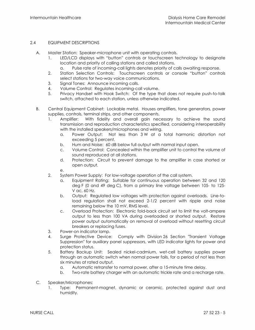
Intermountain Healthcare Dialysis Home Care RemodelIntermountain Medical Center
NURSE CALL 27 52 23 - 5
2.4 EQUIPMENT DESCRIPTIONS
A. Master Station: Speaker-microphone unit with operating controls.1. LED/LCD displays with “button” controls or touchscreen technology to designate
location and priority of calling stations and called stations. a. Pulse rate of incoming-call lights denotes priority of calls awaiting response.
2. Station Selection Controls: Touchscreen controls or console “button” controls select stations for two-way voice communications.
3. Signal Tones: Announce incoming calls.4. Volume Control: Regulates incoming-call volume.5. Privacy Handset with Hook Switch: Of the type that does not require push-to-talk
switch, attached to each station, unless otherwise indicated.
B. Central Equipment Cabinet: Lockable metal. Houses amplifiers, tone generators, power supplies, controls, terminal strips, and other components.1. Amplifier: With fidelity and overall gain necessary to achieve the sound
transmission and reproduction characteristics specified, considering interoperability with the installed speakers/microphones and wiring.a. Power Output: Not less than 3 W at a total harmonic distortion not
exceeding 5 percent.b. Hum and Noise: 60 dB below full output with normal input open.c. Volume Control: Concealed within the amplifier unit to control the volume of
sound reproduced at all stations.d. Protection: Circuit to prevent damage to the amplifier in case shorted or
open output.e.
2. System Power Supply: For low-voltage operation of the call system.a. Equipment Rating: Suitable for continuous operation between 32 and 120
deg F (0 and 49 deg C), from a primary line voltage between 105- to 125-V ac, 60 Hz.
b. Output: Regulated low voltages with protection against overloads. Line-to-load regulation shall not exceed 2-1/2 percent with ripple and noise remaining below the 10 mV, RMS level.
c. Overload Protection: Electronic fold-back circuit set to limit the volt-ampere output to less than 100 VA during overloaded or shorted output. Restore power output automatically on removal of overload without resetting circuit breakers or replacing fuses.
3. Power-on indicator lamp.4. Surge Protective Device: Comply with Division 26 Section "Transient Voltage
Suppression" for auxiliary panel suppressors, with LED indicator lights for power and protection status.
5. Battery Backup Unit: Sealed nickel-cadmium, wet-cell battery supplies power through an automatic switch when normal power fails, for a period of not less than six minutes at rated output.a. Automatic retransfer to normal power, after a 15-minute time delay.b. Two-rate battery charger with an automatic trickle rate and a recharge rate.
C. Speaker/Microphones:1. Type: Permanent-magnet, dynamic or ceramic, protected against dust and
humidity.

Intermountain Healthcare Dialysis Home Care RemodelIntermountain Medical Center
NURSE CALL 27 52 23 - 6
2. Sound Reproduction: Sound level of 90 dB plus or minus 3 dB at a distance of 48 inches on the axis without overdriving or distorting any frequencies between 300 and 3000 Hz when installed in an enclosure or in the pillow speaker.
3. Power Handling Capacity: Not susceptible to damage from overdriving within the range of power available from the amplifier.
4. Impedance Matching: Coordinated and matched to the input and output circuits of the amplifier, both for single connection and for group monitoring, to provide the sound reproduction specified. Subsystems or components shall not be combined, which could cause unacceptable distortion such as feedback between pillow speakers and unmuted room speaker/microphone combinations. This protection shall extend throughout the entire range of operation (volume control) of all components.
D. Single-Patient Station: Each bedside control station shall be capable of the following functions: 1. At least 6 programmable call levels (including associated sub-stations).2. Sound Reproduction: Sound level of 90 dB plus or minus 3 dB at a distance of 48
inches on the axis without overdriving or distorting any frequencies between 300 and 3000 Hz when installed in an enclosure or in the pillow speaker.
3. Entertainment/pillow speaker intercom. 4. Entertainment muting shall occur when nurse call audio is established.5. Support and supervise up to 5 sub-stations including pull-cord, push-button, code
blue, staff register, and fire/auxiliary modules.6. Provide interface to local equipment alarm contacts (i.e. ventilator, IV drip, fire
detector, etc.) to notify console of local alarm condition in patient room.
E. Staff and Duty Stations: Audible call-tone signal device, speaker microphone with dynamic cone, monitor lamp, reset switch, routine-call lamp, emergency-call lamp, and call push button; assembled under a single faceplate.
2.5 MISCELLANEOUS EQUIPMENT COMPONENT DESCRIPTIONS
A. Emergency-Call Station: Locking-type push button, labeled "Push to Call Help"; reset trigger to release push button and cancel call; and call-placed lamp; mounted in a single faceplate.
B. Pull-Cord Call Station (Bath): Water-resistant construction. Includes the following, mounted under a single faceplate:1. Pull-Down Switch: Lever-locking type, labeled "Pull Down to Call Help."2. Reset trigger.3. Call-placed lamp.
C. Call-Button Cord Set (Clinic 4th Floor Recovery): Plug and 72-inch white cord; equipped with momentary-action, call-button switch.1. Ethylene oxide, sterilizable.2. Washable cord.3. Palladium switch contacts in high-impact white housing with cord-set strain relief.4. Attachment: Stainless-steel bed clamp with permanently attached Mylar strap.5. Quantity: 3 cord sets for every 10 patient beds.
D. Indicator Lamps: Light-emitting-diode type with 20-year rated life, unless otherwise indicated.

Intermountain Healthcare Dialysis Home Care RemodelIntermountain Medical Center
NURSE CALL 27 52 23 - 7
E. Station Faceplates: High-impact plastic, color by architect. Molded or machine-engraved labeling identifies indicator lamps and controls.
F. Corridor Dome Lights and Zone Lights: Four-lamp signal lights (minimum).1. Lamps: Front replaceable without tools, low voltage with rated life of 7500 hours.
Barriers are such that only one color is displayed at a time.2. Lenses: Heat-resistant, shatterproof, translucent polymer that will not deform,
discolor, or craze when exposed to hospital cleaning agents.3. Filters: Two per unit, amber and red.
G. Cable: Features include the following, unless otherwise indicated:1. Conductors: Jacketed single and multiple twisted-pair, copper cables. Sizes and
types as recommended by equipment manufacturer. All cable shall be plenum rated.
H. Grounding Components: As specified in Division 26 Section "Grounding."
PART 3 - EXECUTION
3.1 INSTALLATION
A. Wiring Method: Install wiring in raceway except within consoles, desks, and counters; and except in accessible ceiling spaces, where cable wiring method may be used. Use UL-listed plenum cable in environmental air spaces including plenum ceilings. Conceal cable and raceway wiring except in unfinished spaces.
B. Install cables without damaging conductors, shield, or jacket.
C. Do not bend cables, in handling or in installing, to smaller radii than minimums recommended by manufacturer.
D. Pull cables without exceeding cable manufacturer's recommended pulling tensions.1. Pull cables simultaneously if more than one is being installed in same raceway.2. Use pulling compound or lubricant if necessary. Use compounds that will not
damage conductor or insulation.3. Use pulling means, including fish tape, cable, rope, and basket-weave wire or
cable grips, that will not damage media or raceway.
E. Install exposed raceways and cables parallel and perpendicular to surfaces or exposed structural members, and follow surface contours. Secure and support cables by straps, staples, or similar fittings designed and installed so as not to damage cables. Secure cable at intervals not exceeding 30 inches and not more than 6 inches from cabinets, boxes, or fittings.
F. Wiring within Enclosures: Provide adequate length of conductors. Bundle, lace, and train conductors to terminal points with no excess. Provide and use lacing bars in cabinets.
G. Separation of Wires: Separate speaker-microphone, line-level, speaker-level, and power-wiring runs. Run in separate raceways or, if exposed or in same enclosure, provide 12-inch minimum separation between conductors to speaker microphones and

Intermountain Healthcare Dialysis Home Care RemodelIntermountain Medical Center
NURSE CALL 27 52 23 - 8
adjacent parallel power and telephone wiring. Provide separation as recommended by equipment manufacturer for other conductors.
H. Splices, Taps, and Terminations: Make splices, taps, and terminations on numbered terminal strips in junction, pull, and outlet boxes, terminal cabinets, and equipment enclosures. Install terminal cabinets where there are splices, taps, or terminations for eight or more conductors.
I. Impedance and Level Matching: Carefully match input and output impedances and signal levels at signal interfaces. Provide matching networks if required.
J. Identification of Conductors and Cables: Retain color-coding of conductors and apply wire and cable marking tape to designate wires and cables so all media are identified in coordination with system wiring diagrams. Label stations, controls, and indications using approved consistent nomenclature.1. Label each cable within 4 inches of each termination and tap, where it is
accessible in a cabinet or junction or outlet box, and elsewhere as indicated.2. Prepare cable administration drawings to show building floor plans with cable
administration point labeling. Identify labeling convention and show labels for terminal hardware and positions, cables, stations and devices and equipment grounding conductors.
3.2 GROUNDING
A. Ground cable shields and equipment to eliminate shock hazard and to minimize ground loops, common-mode returns, noise pickup, cross talk, and other signal impairments.
B. Signal Ground Terminal: Locate at main equipment cabinet. Isolate from power system and equipment grounding except at connection to main building ground bus.
C. Grounding Provisions: Comply with requirements in Division 26 Section "Grounding."
3.3 FIELD QUALITY CONTROL
A. Manufacturer's Field Service: Engage a factory-authorized service representative to inspect, test, and adjust field-assembled components and equipment installation, including connections, and to assist in field testing. Report results in writing.
B. Test Procedure: Comply with the following:1. Schedule tests a minimum of seven days in advance of performance of tests.2. Report: Submit a written record of test results.3. Operational Test: Perform an operational system test, and demonstrate proper
operations, adjustment, and sensitivity of each station. Perform tests that include originating station-to-station and all-call messages and pages at each nurse call station. Verify proper routing, volume levels, and freedom from noise and distortion. Test each available message path from each station on the system. Meet the following criteria:a. Speaker Output: 90 dB plus or minus 3 dB, 300 to 3000 Hz.b. Gain from patient's bedside station to nurse station, with distortion less than
65 dB (plus or minus 3 dB, 300 to 3000 Hz).
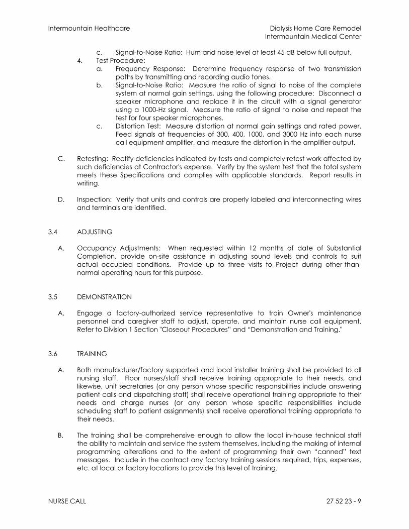
Intermountain Healthcare Dialysis Home Care RemodelIntermountain Medical Center
NURSE CALL 27 52 23 - 9
c. Signal-to-Noise Ratio: Hum and noise level at least 45 dB below full output.4. Test Procedure:
a. Frequency Response: Determine frequency response of two transmission paths by transmitting and recording audio tones.
b. Signal-to-Noise Ratio: Measure the ratio of signal to noise of the complete system at normal gain settings, using the following procedure: Disconnect a speaker microphone and replace it in the circuit with a signal generator using a 1000-Hz signal. Measure the ratio of signal to noise and repeat the test for four speaker microphones.
c. Distortion Test: Measure distortion at normal gain settings and rated power. Feed signals at frequencies of 300, 400, 1000, and 3000 Hz into each nurse call equipment amplifier, and measure the distortion in the amplifier output.
C. Retesting: Rectify deficiencies indicated by tests and completely retest work affected by such deficiencies at Contractor's expense. Verify by the system test that the total system meets these Specifications and complies with applicable standards. Report results in writing.
D. Inspection: Verify that units and controls are properly labeled and interconnecting wires and terminals are identified.
3.4 ADJUSTING
A. Occupancy Adjustments: When requested within 12 months of date of Substantial Completion, provide on-site assistance in adjusting sound levels and controls to suit actual occupied conditions. Provide up to three visits to Project during other-than-normal operating hours for this purpose.
3.5 DEMONSTRATION
A. Engage a factory-authorized service representative to train Owner's maintenance personnel and caregiver staff to adjust, operate, and maintain nurse call equipment. Refer to Division 1 Section "Closeout Procedures” and “Demonstration and Training."
3.6 TRAINING
A. Both manufacturer/factory supported and local installer training shall be provided to all nursing staff. Floor nurses/staff shall receive training appropriate to their needs, and likewise, unit secretaries (or any person whose specific responsibilities include answering patient calls and dispatching staff) shall receive operational training appropriate to their needs and charge nurses (or any person whose specific responsibilities include scheduling staff to patient assignments) shall receive operational training appropriate to their needs.
B. The training shall be comprehensive enough to allow the local in-house technical staff the ability to maintain and service the system themselves, including the making of internal programming alterations and to the extent of programming their own “canned” text messages. Include in the contract any factory training sessions required, trips, expenses, etc. at local or factory locations to provide this level of training.

Intermountain Healthcare Dialysis Home Care RemodelIntermountain Medical Center
NURSE CALL 27 52 23 - 10
END OF SECTION

Intermountain Healthcare Dialysis Home Care RemodelIntermountain Medical Center
APPENDIX 01 – DEVIATION REQUEST PROCESS 276001 - 1
SECTION 276001- APPENDIX 01 – DEVIATION REQUEST PROCESS
PART 1 - GENERAL
1.1 DEFINITIONS
A. Cable Plant Deviation1. A business need to not fully comply with the requirements of the “Division
27 – Communications and Structured Cabling Specification document”B.Cable Plant Deviation Request form.
1. The document is available from the Facilities Planning team, the Data Center Ops team, or the Infrastructure Cabling team.
2. Usage:a. The deviation request form shall be used if there is a business need
to not comply with the requirements of the “Division 27 – Communications and Structured Cabling Specification document”
b. The deviation request form should also be used to propose a change to that document. Always verify that you are using the current version of the Standard before requesting a modification.
PART 2 - PROCESS
2.1 STANDARDS MODIFICATION
A. Check the box and explain why the standard should be modified.
2.2 ALTERNATE PRODUCT
A. The deviation form must be completed, submitted through channels, and approved prior to any deviation from the specifications. This includes issuing change orders.
2.3 AUTHORIZED SIGNATURES
A. Both the Standards Holder and the DCO Manager signatures are required for a deviation to be valid.
2.4 DEVIATION REVIEW PROCESS STEPS
A. First be sure that there is an actual need. Then be certain that your manager, supervisor, or project manager agrees with the requested deviation. Be sure to state this or obtain their signature on the deviation form. By doing so you are confirming that your supervisor or project manager has approved.
B.The requestor will then complete sections 1, 2, and 3 of the deviation form. 1. The requestor should then digitally sign in the designated location at the
end of Section 3. Do not write in the sections below 3.C. Forward the saved copy of this form to the Standards Holder via email.
1. Email to: [email protected]. The Standards Holder will then review and evaluate the request. The requestor
should be prepared to provide plans, specifications, and competitive bids if

Intermountain Healthcare Dialysis Home Care RemodelIntermountain Medical Center
APPENDIX 01 – DEVIATION REQUEST PROCESS 276001 - 2
requested. Any email threads or meeting discussions regarding the issue will be taken into consideration.
E. The Standards Holder will then cast an Approve or Deny vote and forward the request to the DCO Manager for a decision.
F. When the decision has been made by the Operations Manager, the Standards Holder will then notify the requestor by returning the completed and signed form via email.
G. An approved deviation will have the final disposition button ‘Approved’ and be signed by at least 2 people. One will be from the Standards Holder, and the other the DCO Manager. Other signatures may be required for specific features and areas such as Safety, Security, Print, Medical group, etc.
PART 3 - EXECUTION
3.1 POST DECISION EXECUTION
A. DENIED1. If the requester is not satisfied with the decision, they may file an appeal
with the Data Center Operations manager ([email protected]), who will then escalate the issue to the appropriate business leaders as needed. The decision from the appeal is final.
B.APPROVED1. If a deviation is approved for contracted material, labor, or method; the
facilities project manager will arrange for fulfillment or contract adjustment as needed via appropriate contract channels such as change orders.
END OF SECTION

Intermountain Healthcare Dialysis Home Care RemodelIntermountain Medical Center
APPENDIX 02 – DEVIATION REQUEST PROCESS 276002 - 1
SECTION 276002 - APPENDIX 02 – DOCUMENT REFRESH PROCESS
PART 1 - GENERAL
1.1 NOT USED
PART 2 - PRODUCTS
2.1 APPROVED PRODUCT
A. The purpose of this section is to help ensure a current standards document.B.The product delivered will be a current revision or version of the Cable Plant Standards
Document.C. All changes must be approved by Enterprise Infrastructure Cabling team.
PART 3 - EXECUTION
3.1 REVIEWS AND UPDATES
A. Minor updates1. Changes that do not significantly affect scope of work, or contract pricing
will be made, and the Rev number will be updated. (i.e. updated part numbers, etc.)
2. Significant changes will be added to the Change Log for review and approval from the DCO/Infrastructure Cabling Team.a. When approved, they will be submitted for approval; and then
implemented in the new Version.B.Major updates
1. The DCO/Infrastructure Cabling Team will review the entire document at least once every three years.
2. This review will coincide with the release of new versions of NFPA70 (National Electrical Code) (2017, 2020, etc. - to be completed by the end of each designated year).
3. The review will cover standards adjustments that may be deemed necessary and ensure compliance with applicable codes and standards.
4. Upon completion of the reviews and updates, the standards document will be submitted for approval.
END OF SECTION

Intermountain Healthcare Dialysis Home Care RemodelIntermountain Medical Center
APPENDIX 03 – DATA CENTER, TEC, TDR PART NUMBERS 276003 - 1
SECTION 276003
APPENDIX 03 – DATA CENTER, TEC, TDR PART NUMBERS
ITEM MANUFACTURER PART NO. DESCRIPTIONBlanking Panel Upsite Hotlok 10031 Blanking Panel 1UBlanking Panel Upsite Hotlok 10033 Blanking Panel 2UUPS Eaton 9PX1500R Eaton Powerware 9PX-1500VUPS Network Card Eaton NETWORK-M Card for 9PX-1500VAPDU Eaton ePBZ79 Horizontal Mount ePDU 208vacPDU Eaton ePBZ82 Horizontal Mount ePDU 120vacPDU Server Technology C1S24VS-YCFA13C9 Vertical 30A PDU (Blue) for TECPDU Server Technology C1L24VS-YCFA13C9 Vertical 30A PDU (Red) for TECPDU Server Technology C2SG36TE-YCMFAM66/C Vertical 30A PDU (Blue) for
Data CentersPDU Server Technology C2LG36TE-YCMFAM66/C Vertical 30A PDU (Red) for
Data CentersPDU Server Technology C2SG36TE-DQME2M66/ZB Vertical 60A PDU (Blue) for
Data CentersPDU Server Technology C2LG36TE-DQME2M66/ZR Vertical 60A PDU (Red) for
Data CentersUPS Eaton K41512000000000 Eaton 9155-15kVA UPSModbus Card Eaton 103005425-5591 Eaton Modbus Card X-SlotReverse Transfer UPS System Eaton 9GPV15C0009E00R2 Eaton 93PM-150kW Reverse
Transfer UPS SystemCRAC Cooling Unit Liebert DE363GVertical Wall Mount Cabinets Legrand VWMSD-4RU-42-B 42” 12” 4RU FixedVertical Wall Mount Cabinets Legrand VWMSD-8RU-42-B 42” 18” 8RU FixedRail Accessories Legrand VWM-RR-4RU Fixed Mounting Rail Kit, 4RURail Accessories Legrand VWM-RR-8RU Fixed Mounting Rail Kit, 8RURail Accessories Legrand VWM-PIV-4RU Pivoting Mounting Rail Kit, 4RUFan Kit Legrand VWMFK-115 VWM Fan Kit w/115 VAC Fans
(includes 2 fans and mounting hardware) (2 kits needed for 8RU cabinet)
VWM Top Brush Grommet Kit Legrand VWMBGK VWM Top Brush Grommet KitCircular Knockout Grommet Kit Legrand VWMGR-30 Circular Knockout Grommet KitVertical Wall-Mount Cabinets Hubbell IR221APG Refrigerated cabinet 24”Vertical Wall-Mount Cabinets Hubbell IR321APG Refrigerated cabinet 36”Vertical Wall-Mount Cabinets Hubbell IR421APG Refrigerated cabinet 48”Air Conditioners Hubbell IRAC1 Air conditioner for Hubbell
refrigerated cabinetsCylinder Medeco 100500 G 1 ¼” Mortise CylinderCylinder Medeco 100400H G Rim Cylinder, Horizontal
TailpieceCylinder Medeco EA-100108 Small Format Interchangeable
Core (SFIC) CylinderCylinder Medeco 20200S1 G Cylinder Package for SchlageCam Lock Medeco EN-150002-219 7/8” Cam Lock Assembly, Key
Retaining

Intermountain Healthcare Dialysis Home Care RemodelIntermountain Medical Center
APPENDIX 03 – DATA CENTER, TEC, TDR PART NUMBERS 276003 - 2
Cam Lock Medeco EN-150003-219 1 1/8” Cam Lock Assembly, Key Retaining
Cylinder for Legrand cabinet front door
Medeco 232301S 800 G Modular Profile Cylinder – 30mm Half Profile - Assembled
Electronic Key Medeco 94-0271 Medeco Slim Line Key (G2) & Charger Bundle
Programming Station for Small Locations
Medeco EA-100109 Medeco XT Desktop USB Programming Station (not preferred)
Programming Station for Large Locations
Medeco EA-100158 Medeco XT Wall USB Programming Station (preferred)
Wall Mount for Wall Programmer
Medeco 94-0294 Medeco XT Remote Wall Programmer Wall Mount Kit
Padlock for use with Electronic Cylinder
Master 6842D045KZ Padlock
Red C20 C19 Dual Lock 12 gauge 6'
Stay Online 5914 Red C20 C19 Dual Lock 12 gauge 6'
Blue C20 C19 Dual Lock 12 gauge 6'
Stay Online 6766 Blue C20 C19 Dual Lock 12 gauge 6'
Red C14 Locking C15 Notched 14 gauge 6'
Stay Online 9144 Red C14 Locking C15 Notched 14 gauge 6'
Blue C14 Locking C15 Notched 14 gauge 6'
Stay Online 9138 Blue C14 Locking C15 Notched 14 gauge 6'
Red C14 C13 Dual Lock 18 gauge 6'
Stay Online 5656 Red C14 C13 Dual Lock 18 gauge 6'
Blue C14 C13 Dual Lock 18 gauge 6'
Stay Online 6694 Blue C14 C13 Dual Lock 18 gauge 6'

Intermountain Healthcare Dialysis Home Care RemodelIntermountain Medical Center
APPRENDIX 04 – REFERENCE STANDARDS 276004 - 1
SECTION 276004 - APPENDIX 04 – REFERENCE STANDARDS
PART 1 - GENERAL
1.1 REFERENCE STANDARDS
A. Codes and Standards (Most recent editions with addenda/TSB, etc.) All materials, installation and workmanship shall meet or exceed the applicable requirements and standards addressed within the references listed below:1. ANSI/TIA-568.0-D and addenda “Generic Telecommunications Cabling for
Customer Premises2. ANSI/TIA-568.1-D and addenda “Commercial Building Telecommunications
Cabling Standard 3. ANSI/TIA-568.2-D and addenda “Balanced Twisted-Pair Telecommunications
Cabling and Components 4. ANSI/TIA-568.3-D and addenda “Optical Fiber Cabling Components Standard”5. ANSI/TIA-568.4-D and addenda “Broadband Coaxial Cabling and Components
Standard”6. ANSI/TIA-569-D and addenda “Telecommunications Pathways and Spaces”7. ANSI/TIA-606-C and addenda “Administration Standard for Commercial
Telecommunications Infrastructure”8. ANSI/TIA-607-D and addenda “Generic Telecommunications Bonding and
Grounding (Earthing) for Customer Premises”9. ANSI/TIA-758-B “Customer-Owned Outside Plant Telecommunication
Infrastructure Standard”10. IEEE 802.3at PoE Plus and Next Gen PoE CFI March 2013 and IEEE P802.3ba
latest draft revision and amendments.11. “Media Access Control Parameters, Physical Layers and Management
Parameters for 40 Gbp/s and 100 Gbp/s Operation”.12. ANSI/TIA-526-7-A “Measurement of Optical Power Loss of Installed Single-Mode
Fiber Cable Plant”13. ANSI/TIA/EIA-526-14-C “Optical Power Loss Measurements of Installed
Multimode Fiber Cable Plant”14. ANSI/TIA-942-B “Telecommunications Infrastructure Standard for Data Centers” 15. ANSI/TIA – 1179-A “Healthcare Facility Telecommunications Infrastructure
Standard”16. IEC/TR3 61000-5-2 - Ed. 1.0 and amendments “Electromagnetic compatibility
(EMC) - Part 5: Installation and mitigation guidelines - Section 2: Earthing and cabling”
17. ISO/IEC 11801-1 (2017) and amendments “Information technology - Generic cabling for customer premises – PART 1: General Requirements”
18. EN 50173-1 and amendments “Information Technology - Generic cabling systems – PART 1 General Requirements”
19. AIA Guidelines for Design and Construction of Hospital and Healthcare Facilities20. Construction Specification Institute Master Format21. BICSI: Comply with the most current editions of the following BICSI manuals:
a. BICSI - Telecommunications Distribution Methods Manualb. BICSI – Installation Transport Systems Information Manualc. BICSI – Network Design Reference Design Manuald. BICSI – Outside Plant Design Reference Manuale. BICSI – Wireless Design Reference Manualf. BICSI -Electronic Safety and Security Design Reference Manualg. Infocomm/BICSI – AV Design Reference Manual
22. Underwriters Laboratories (UL) Cable Certification and Follow-Up Program.23. National Electrical Manufacturers Association (NEMA)

Intermountain Healthcare Dialysis Home Care RemodelIntermountain Medical Center
APPRENDIX 04 – REFERENCE STANDARDS 276004 - 2
24. American Society for Testing Materials (ASTM)25. National Electrical Code (NEC) NFPA70 202026. National Electrical Safety Code (NESC) 201727. Institute of Electrical and Electronic Engineers (IEEE)28. UL Testing Bulletin29. Building Industry Consulting Services International (BICSI) Information Transport
Systems Methods Manual (ITSMM)30. Local, county, state and federal regulations and codes in effect as of date of
installation.31. Equipment of foreign manufacture must meet U.S. codes and standards. It shall
be indicated in the proposal the components that may be of foreign manufacture, if any, and the country of origin.
END OF SECTION

Intermountain Healthcare Dialysis Home Care RemodelIntermountain Medical Center
APPENDIX 05 – DEFINITIONS AND ABBREVIATIONS 276005 - 1
SECTION 276005 - APPENDIX 05 – DEFINITIONS AND ABBREVIATIONS
PART 1 - GENERAL
1.1 RELATED TERMS
A. Codes and Standards (Most recent editions with addenda/TSB, etc.) All materials, installation and workmanship shall meet or exceed the applicable requirements and standards addressed within the references listed below:1. Basket Cable Tray: A fabricated structure consisting of wire mesh bottom and
side rails.2. BICSI: Building Industry Consulting Service International. 3. CBC: Coupled Bonding Conductor4. CFCI: Customer Furnished Customer Installed5. Cable Run - A single cable to a single location6. Cable Drop - Two cables to a single location7. Cable Tri Drop - Three cables to a single location8. CT Coupler A type of wall connector made by the Siemon Company9. DCO: Data Center Operations10. Div.1: Division 1 General and Performance Requirements11. Div. 23: Division 23 Heating, Ventilating, and Air Conditioning12. Div. 22: Division 22 Plumbing13. Div. 26: Division 26 Electrical 14. Div. 27: Division 27 Communications and Audio Visual15. Div. 28: Division 28 Electronic Safety and Security16. E.E.: Electrical Engineer17. EMI: Electromagnetic Interference18. F/UTP: Foil over Unshielded Twisted Pair. Individual pairs are unshielded.19. GC: General Contractor20. GE: Ground Equalizer21. Horizontal Cabling: The cable and connecting hardware utilized to transport
communications signals22. ICT: Infrastructure Cabling Team23. LAN: Local Area Network24. N/A: Not Applicable25. NIC: Not in Contract26. OFCI: Owner Furnished Contractor Installed27. OFOI: Owner Furnished Owner Installed28. OTDR: Optical Time Domain Reflectometer29. Outlet/Connectors: A connecting device in the work area on which horizontal
cable or outlet cable terminates.30. RCDD: Registered Communications Distribution Designer31. RFI: Radio Frequency Interference32. TBA or TBD: To Be Determined33. TDR: Technology Distribution Room34. TEC: Technology Equipment Center35. TGB: Telecommunications Ground Bus Bar36. TMBC: Telecommunications Main Bonding Conductor37. TMGB: Telecommunications Main Grounding Bus Bar38. TSER: Telecommunications Service Entrance Room39. UTP: Unshielded Twisted Pair40. Work Area: approx. 100 sq. ft. equipped for workstation equipment

Intermountain Healthcare Dialysis Home Care RemodelIntermountain Medical Center
APPENDIX 05 – DEFINITIONS AND ABBREVIATIONS 276005 - 2
41. DCO = Data Center Operations – [email protected]. ICT = Information and Communications Technology – [email protected]
END OF SECTION

Intermountain Healthcare Dialysis Home Care RemodelIntermountain Medical Center
APPENDIX 06 – MATERIAL SUPPLIERS 276006 - 1
SECTION 276006 - APPENDIX 06 – MATERIAL SUPPLIERS
PART 1 - GENERAL
1.1 RELATED TERMS
A. Siemon Authorized Suppliers are listed below. To help prevent counterfeiting and support warranties, known, factory authorized distributers are recommended.1. Approved Suppliers of Siemon cable, patch panels, jacks, and parts:
Anixter
Randi WhittakerInside Sales Main Phone: (801) 973-21213775 W. California Ave. Ste 400 Fax: (801) 973-4472Salt Lake City, UT 84104 US Email: [email protected]
Karl BartlamEnd User/Outside Sales Main Phone: (801) 973-21213775 W. California Ave. Ste 400 Fax: (801) 973-4472Salt Lake City, UT 84104 US Email: [email protected]
Graybar Electric
Elizabeth VaughnInside Sales Main Phone: (801) 656-30162841 South 900 West Fax: (801) 973-4314Salt Lake City, UT 84119 US Email: [email protected]
Erika Morrison Contractor Outside Sales Main Phone: (801) 656-30142841 South 900 West Fax: (801) 973-4314Salt Lake City, UT 84119 US Email: [email protected]
WESCO / CSC
Brian WaltersInside Sales Main Phone: (801) 975-06003210 South 900 West Fax: (801) 907-4450Salt Lake City, UT 84119 US Email: [email protected]
Adam Tueller Contractor Outside Sales Main Phone: (801) 975-06003210 South 900 West Direct: (801) 618-6665Salt Lake City, UT 84119 US Email: [email protected]
B.The Siemon Company is represented locally by: [email protected]
END OF SECTION

Intermountain Healthcare Dialysis Home Care RemodelIntermountain Medical Center
APPENDIX 07 – CERTIFIED INSTALLATION FIRMS 276007 - 1
SECTION 276007 - APPENDIX 07 – SIEMON CERTIFIED INSTALLATION FIRMS
PART 1 - GENERAL
1.1 RELATED TERMS
A. NOTE: Cable installers have rigorous requirements to be certified for Siemon cables and products. Validation of certification is required prior to accepting a bid.
B.The firms selected to bid must be pre-approved by the local facility IT manager. Installation firms desiring to do work for Intermountain Healthcare must be selected from the official CI list below.
C. Current Siemon Approved/Certified Cable Installers for Siemon Network Cable. This list is up to date as of 2018-12-01.1. Orion Integration Group: 8880 W. Barnes Street, Boise, ID 83709 /
Phone 208 321 80002. ACS Systems: 925 North Main St. Meridian, ID 83642 / Phone 208 331 85543. IES Commercial: 1960 S. Milestone, Suite D, Salt Lake City, UT 84104
a. Jason King – Branch Manager // Phone 801 975 8182 / Fax 385 242 7366 / Mobile 801 381 1508 // [email protected] / www.iescomm.com
b. Boyd Evans – Project Manager // Phone 801 975 8191 / Fax 385 242 7366Mobile 801 381 1518 // [email protected] /
www.iescomm.com 4. Cache Valley Electric: 1338 S. Gustin Rd., Salt Lake City, UT 84104
a. Travis Grant – Acct. Manager // Phone 801 908 4170 / Fax 801 908 7401 Mobile 801 870 7226 // [email protected] / www.cve.com
b. Brad Readicker – Acct. Manager // Phone 801 908 2686 / Fax 801 908 7401 // [email protected] / www.cve.com
5. Data Tech Professionals: 1199 S 520 W, Payson, UT 84651a. Jesse Pierce – President // Phone 801 960 2202 / Mobile 801 420 0463
[email protected] / www.datatechprofessionals.com
6. Hunt Electric, Inc.: 1863 W. Alexander St., Salt Lake City, UT 84119a. Darrin Guevara – Division Manager // Phone 801 975 8844
[email protected] / www.huntelectric.com 7. NCNS Communications: 419 West Universal Circle, Sandy, UT 84070
a. Jayson Nosack – Owner // Phone 801 361 4572 [email protected] / www.ncns-co.com
8. Data Plus: 769 Middlegate Road, Henderson, NV 89118 a. Chris Tettamanti – Project Manager // Phone 702 795 3282
[email protected]. Bombard Electric: 4380 West post Road, Las Vegas, NV 89118
a. Bob Reese – Project/Division Manager // Phone 702 263 [email protected] / www.bombardelectric.com
10. Rosendin Electric: 7470 Dean Martin Dr. #112, Las Vegas, NV 89139a. Cora Shadbolt – Assistant Project Mgr. // Phone 702 258 1443
[email protected] b. Adrian Youngblood – Sr. Estimator // Phone 702 258 1455

Intermountain Healthcare Dialysis Home Care RemodelIntermountain Medical Center
APPENDIX 07 – CERTIFIED INSTALLATION FIRMS 276007 - 2
c. Breck Hardesty – Sr. Project Mgr. // Phone 702 258 [email protected] / www.rosendin.com
11. Mojave Electric: 3755 W. Hacienda Ave., Las Vegas, NV 89118 Phone 702 798 2970
12. The Morse Group: 3874 Silvestri Lane, Las Vegas, NV 89120 Phone 702 257 4400
END OF SECTION

Intermountain Healthcare Dialysis Home Care RemodelIntermountain Medical Center
APPENDIX 08 – LEAD WALL PENETRATIONS 276007 - 1
SECTION 276008 - APPENDIX 08 – LEAD WALL PENETRATIONS
PART 1 - GENERAL
1.1 RELATED DOCUMENTS
A. Sections 13090 & 134900
1.2 RELATED TERMS
Procedure Name: New Port and Electrical Box Installation Lead Lined WallsDocument Detail Information: (This section must be completed in full.)Implements Policy: Click here to enter policy title
Content Owner
Craig Allen, Safety Security Environment Health Director, Central OfficeJeremy Hawk Medical Physicist Radiation Safety Coordinator
Content Consultant(s):
Jeremy Hawk, Radiation Safety Officer, Medical Physicist Imaging
John Ellis, Facilities Management Director, Central OfficeSteve Kelly, System Project Facility Design Manager, PlanningMelissa Lopez, Cabling, IS
Date of Final Draft: 12/29/2015 Who Reviewed Content? <Name, Title, Dept>
<Name, Title, Dept><Name, Title, Dept>
Keywords (must have at least 3):
Searchable Keywords (e.g., PHI, EMTALA, Coding) <Committee Name>
1.3 PURPOSE
A. Maintain radiation safety controls in lead lined walls during installation of new power and data outlets in existing lead lined walls.
1.4 SCOPE
A. Intermountain Hospitals, Intermountain Clinics Medical Group
1.5 DEFINITIONS
A. Lead lined Walls – Structured element designed to provide a barrier to block radiation penetration beyond the designated space.
B.Maintenance Manager – The person responsible for plant maintenance operations or his/her delegate.
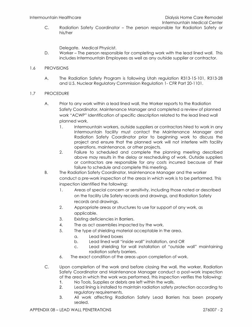
Intermountain Healthcare Dialysis Home Care RemodelIntermountain Medical Center
APPENDIX 08 – LEAD WALL PENETRATIONS 276007 - 2
C. Radiation Safety Coordinator – The person responsible for Radiation Safety or his/her
Delegate. Medical Physicist.D. Worker – The person responsible for completing work with the lead lined wall. This
includes Intermountain Employees as well as any outside supplier or contractor.
1.6 PROVISIONS
A. The Radiation Safety Program is following Utah regulation R313-15-101, R313-28 and U.S. Nuclear Regulatory Commission Regulation 1- CFR Part 20-1101.
1.7 PROCEDURE
A. Prior to any work within a lead lined wall, the Worker reports to the Radiation Safety Coordinator, Maintenance Manager and completed a review of planned work “ACWP” Identification of specific description related to the lead lined wall planned work.1. Intermountain workers, outside suppliers or contractors hired to work in any
Intermountain facility must contact the Maintenance Manager and Radiation Safety Coordinator prior to beginning work to discuss the project and ensure that the planned work will not interfere with facility operations, maintenance, or other projects.
2. Failure to scheduled and complete the planning meeting described above may results in the delay or rescheduling of work. Outside suppliers or contractors are responsible for any costs incurred because of their failure to schedule and complete this meeting.
B. The Radiation Safety Coordinator, Maintenance Manager and the worker conduct a pre-work inspection of the areas in which work is to be performed. This inspection identified the following:1. Areas of special concern or sensitivity, including those noted or described
on the facility Life Safety records and drawings, and Radiation Safety records and drawings.
2. Appropriate areas or structures to use for support of any work, as applicable.
3. Existing deficiencies in Barriers.4. The as act assemblies impacted by the work.5. The type of shielding material acceptable in the area.
a. Lead lined boxesb. Lead lined wall “inside wall” installation, and ORc. Lead shielding for wall installation of “outside wall” maintaining
radiation safety barriers.6. The exact condition of the areas upon completion of work.
C. Upon completion of the work and before closing the wall, the worker, Radiation
Safety Coordinator and Maintenance Manager conduct a post-work inspection of the area in which the work was performed, this inspection verifies the following:1. No Tools, Supplies or debris are left within the walls.2. Lead lining is installed to maintain radiation safety protection according to
regulatory requirements.3. All work affecting Radiation Safety Lead Barriers has been properly
sealed.

Intermountain Healthcare Dialysis Home Care RemodelIntermountain Medical Center
APPENDIX 08 – LEAD WALL PENETRATIONS 276007 - 3
4. The overall condition of the area meets the expectation outline in the per-work inspection.
E. The Maintenance Manager and Radiation Safety Coordinator signs and logs the completed “ACWP”
1.8 EXCEPTIONS
A. None.
1.9 PRIMARY SOURCES
A. List the regulatory references upon which the procedure is based (cite the code, the title, and the statute).
1.10 SECONDARY MATERIALS
A. Radiation Safety PolicyB. Above Ceiling Work PermitC. Lead lined wall requirements as defined by Radiation Safety Building
Requirements

Intermountain Healthcare Dialysis Home Care RemodelIntermountain Medical Center
APPENDIX 08 – LEAD WALL PENETRATIONS 276007 - 4
END OF SECTION