Embed Size (px)
Citation preview

Body sizePort size
Flow rate characteristics *1 Applicable cylinder *2
C [dm3/(s·bar)] ø63 ø80 ø100 ø125
Body
porte
d VEX312 1/4 3.5
VEX332 3/8 8.7
Base
mou
nted
VEX322 1/4 4.4
VEX342 1/2 14
Intermediate stopping of cylinders up to ø125*
is possible.
Power consumption: 1 w
Variations
*1 For 2 (A) → 3 (R) *2 For 300 mm/s, horizontal movement
Pilot Solenoid Air Operated
3 Manual override options added
Locking slotted type Push-turn lockingslotted type
Push-turn lockinglever type
Air operated
Manifold
For Grommet/Plug connector For DIN terminal For DIN terminal
* For VEX3342, 300 mm/s, horizontal movement
Pilot solenoid
3 Port 3 Position ValveVEX3 Series
1721
RoHS
VEXVEX

3 x 3 = 9 positions
P1
3(R)
1(P)
2(A)
Suctionfilter
3(R)
1(P)
2(A)
Vacuumpad
Vacuumpump
Pressurizedair
3 port 3 position valve
Vacuum suction and releaseThe 3-port, 3-position double solenoid that permits vacuum suc-tion, release, and suspension (closed) is ideal for a system where many valves are used.
There is no blow-by when switched from vacuum suction to vacuum release or vice versa.
When maintaining the vacuum of port 2(A), the vacuum may decrease due to leakage from the vacuum pad or piping. Conduct vacuum suction at the vacuum adsorption position. Furthermore, it cannot be used as an emergency cutoff valve.
Caution
Intermediate cylinder stops3-position closed center type. A system with a more simple design, but the same size, is now available.
A large capacity system without connection loss
1 1 0.71 (Valves and piping can be made smaller.)
2(A)
1(P)
3(R)
2(A) 1
(P)
3(R)
P2
3 port 3 position valve
Terminal deceleration and an intermediatespeed change circuit can be produced easily.The simple system configuration permits sharp response. The large capacity system configuration without connection loss allows the use of smaller valves and piping. For example, when solenoid b of valve A is turned off while the cylinder is
extending, the exhaust port closes and cylinder movement decelerates.
1 1 1 0.58(Emergency stop valve)
(Speed change valve)
(Switching valve)
A
3 port 3 position valve
Universal porting could be used as a selector/divider valve.The pressure balancing poppet valve that permits any flow direction allows sequential switching operation, preventing blow-by and air entrainment.
Direction divider 3 port 3 position valve
Two-stage directional control selection3 port 3 position valve
For operation control of double acting cylindersTwo 3-port 3-position valves driven by a double acting cylinder allow operation control in 9 positions (3 positions x 3 positions = 9 positions) including slow stopping, acceleration, and deceleration.
37159
Reciprocation
Pressure centerClosed centerExhaust center
2468
Pressure &closed centerExhaust &closed center
Slow stoppingor deceleration
B N aA b n
3 Port 3 Position Valve VEX3 Series
Applications
This valve allows air leakage, and thus cannot be used for long term intermediate stops.Caution
37159
Reciprocation
Pressure centerClosed centerExhaust center
2468
Pressure &closed centerExhaust &closed center
Slow stoppingor deceleration
B N aA b n
Stroke
Stroke
Time
Time
Stroke
Stroke
Time
Time
1722

SystemAverage speed[mm/s]
Bore size
MB, CA2 seriesPressure 0.5 MPa, Load ratio 50%, Stroke 500 mm
ø40 ø50 ø63 ø80 ø100
A
1000900800700600500400300200100
0
B
1000900800700600500400300200100
0
C
1000900800700600500400300200100
0
SystemAverage speed[mm/s]
Bore size
CS1/CS2 seriesPressure 0.5 MPa, Load ratio 50%, Stroke 300 mm
ø125 ø140 ø160 ø180 ø200
D
600500400300200100
0
* Values at extension of a directly coupled cylinder when meter-out speed controllers are used with the needle full open.* The average speed of the cylinder is obtained by dividing the stroke by the total stroke time.* The load ratio is obtained by the following formula: ((Load mass x 9.8)/Theoretical output) x 100%
ConditionsSystem Solenoid valve Speed controller Silencer Tubing diameter x Length
AVEX31
22-02 AS4000-02 AN20-02ø10 x 1 m
B ø12 x 1 m
CVEX33
42-0304
AS420-03 AN30-03 ø12 x 1 m
D AS420-04 AN40-04 SGP15A x 1 m
Vertically upward
Horizontal
This chart is provided as guidelines only. For performance under various conditions, use SMC’s Model Selection Software before making a judgment.
3 Port 3 Position Valve VEX3 Series
Cylinder Speed Chart
1723
VEXVEX

How to Order
3 Port 3 Position ValveBody PortedVEX3 Series
VEX3 B12 0 01 1
Operation type1 External pilot solenoid2 Internal pilot solenoid
Electrical entryGrommet L plug connector M plug connector DIN terminal
G: Lead wirelength 300 mm
L: With lead wire(Length: 300 mm)
M: With lead wire(Length: 300 mm)
MN: Without lead wire D: With connector
H: Lead wirelength 600 mm
LN: Without lead wire LO: Without connector MO: Without connector DO: Without connector
CE-compliant
DCAC — — — —
OptionNil None —
BBracket
(VEX312 only)
F
Footbracket
(VEX312 and VEX332 only)
VEX312 VEX332
N*Pilot
exhaust (PE) silencer
* Only with solenoid
Body size Port sizeBody size
Port sizePort 1(P), 2(A), 3(R)
12 01 1/802 1/4
3202 1/403 3/804 1/2
Thread typeNil RcF GN NPTT NPTF
Manual override
Nil Non-lockingpush type
Grommet/ (L/M) plug connector
DIN terminal
B Locking slotted type
Grommet/ (L/M) plug connector
DPush-turn
lockingslotted type
DIN terminal
E*Push-turn
lockinglever type
DIN terminal
* Except external pilot solenoid
Light/surge voltage suppressorElectrical entry for G, H, L, M DC AC
Nil None
R With surge voltage suppressor (Non-polar type) —U With light/surge voltage suppressor (Non-polar type) —Z With light/surge voltage suppressor —
Electrical entry for D DC ACNil None
S With surge voltage suppressor —Z With light/surge voltage suppressor
* DOZ is not available.* There is no S option for AC mode, since a rectifier prevents surge
voltage generation.
VEX3 D B5 1
Rated voltage1 100 VAC (50/60 Hz)2 200 VAC (50/60 Hz)3 110 VAC (50/60 Hz)4 220 VAC (50/60 Hz)5 24 VDC6 12 VDCV 6 VDCS 5 VDCR 3 VDC
* DC specification of type D and DO is only available with 12 and 24 VDC.
12 2 01
Air operated Pilot solenoid
Air operated
Pilot solenoid
1724
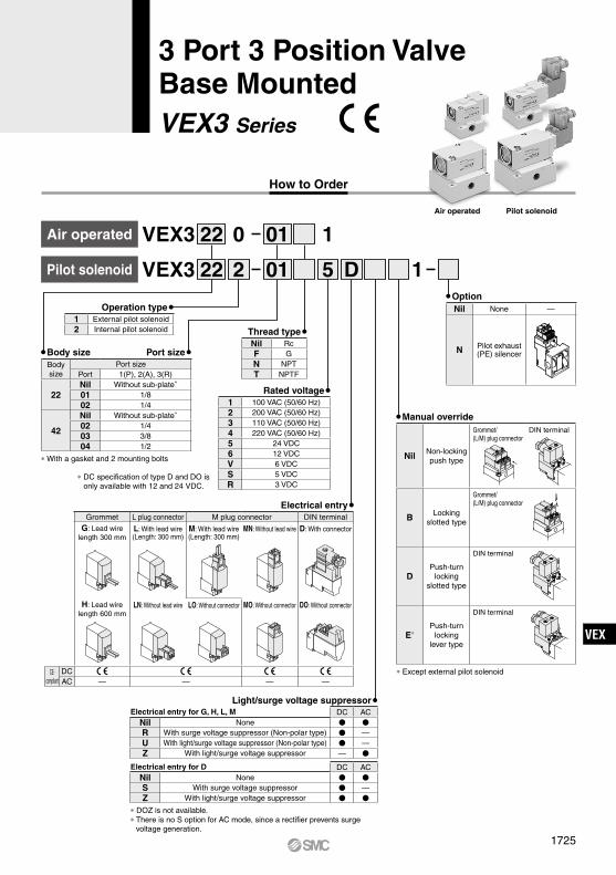
3 Port 3 Position ValveBase MountedVEX3 Series
How to Order
VEX3 22 0 01 1
OptionNil None —
N Pilot exhaust (PE) silencerBody size Port size
Body size
Port sizePort 1(P), 2(A), 3(R)
22Nil Without sub-plate*
01 1/802 1/4
42
Nil Without sub-plate*
02 1/403 3/804 1/2
* With a gasket and 2 mounting bolts
VEX3 D5 122 2 01
Air operated Pilot solenoid
Air operated
Pilot solenoid
Operation type1 External pilot solenoid2 Internal pilot solenoid
Electrical entryGrommet L plug connector M plug connector DIN terminal
G: Lead wirelength 300 mm
L: With lead wire(Length: 300 mm)
M: With lead wire(Length: 300 mm)
MN: Without lead wire D: With connector
H: Lead wirelength 600 mm
LN: Without lead wire LO: Without connector MO: Without connector DO: Without connector
CE-compliant
DCAC — — — —
Thread typeNil RcF GN NPTT NPTF
Manual override
Nil Non-lockingpush type
Grommet/ (L/M) plug connector
DIN terminal
B Locking slotted type
Grommet/ (L/M) plug connector
DPush-turn
lockingslotted type
DIN terminal
E*Push-turn
lockinglever type
DIN terminal
* Except external pilot solenoid
Light/surge voltage suppressorElectrical entry for G, H, L, M DC AC
Nil None
R With surge voltage suppressor (Non-polar type) —U With light/surge voltage suppressor (Non-polar type) —Z With light/surge voltage suppressor —
Electrical entry for D DC ACNil None
S With surge voltage suppressor —Z With light/surge voltage suppressor
* DOZ is not available.* There is no S option for AC mode, since a rectifier prevents surge
voltage generation.
Rated voltage1 100 VAC (50/60 Hz)2 200 VAC (50/60 Hz)3 110 VAC (50/60 Hz)4 220 VAC (50/60 Hz)5 24 VDC6 12 VDCV 6 VDCS 5 VDCR 3 VDC
* DC specification of type D and DO is only available with 12 and 24 VDC.
1725
VEXVEX

This is not a manual override. Do not press this button, as it can result in damage to the product. This applies to body sizes 1 and 2.
Specifications
Pilot Solenoid Valve Specifications
Air operated
Internal pilot solenoid / External pilot solenoid
Air operated External pilot solenoid Internal pilot solenoid
Symbol
ModelVEX3121, VEX3221, VEX3321, VEX3421VEX3122, VEX3222, VEX3322, VEX3422
Pilot valve V114, V115
Electrical entryGrommet (G), L plug connector (L),
M plug connector (M), DIN terminal (D)
Rated coilvoltage [V]
AC (50/60 Hz) 100 V, 110 V, 200 V, 220 VDC 3 V, 5 V, 6 V, 12 V, 24 V
Allowable voltage fluctuation –10 to +10% of rated voltage*
Apparent power [VA]
AC
G, L, M
100 V 0.78 (With indicator light: 0.81)110 V 0.86 (With indicator light: 0.89)200 V 1.18 (With indicator light: 1.22)220 V 1.30 (With indicator light: 1.34)
D
100 V 0.78 (With indicator light: 0.87)110 V 0.86 (With indicator light: 0.97)200 V 1.15 (With indicator light: 1.30)220 V 1.27 (With indicator light: 1.46)
Power consumption [W]
DCG, L, M 1.0 (With indicator light: 1.1)
D 1.0 (With indicator light: 1.1)
* Allowable voltage fluctuation for S and Z types 24 VDC: −7% to +10%12 VDC: −4% to +10%
ModelBody ported VEX312-01
02 VEX332-020304
Base mounted VEX322-0102 VEX342-
020304
Operation type Air operated, External pilot solenoid, Internal pilot solenoidFluid AirAir operated operating pressure range[MPa]
Operating pressure range −101.2 kPa to 1.0Pilot pressure range 0.2 to 1.0
Internal pilot operating pressure range [MPa] 0.2 to 0.7External pilot operating pressure range[MPa]
Operating pressure range −101.2 kPa to 1.0Pilot pressure range 0.2 to 0.7
Ambient and fluid temperature 0 to 50°C (Air operated: 60°C)
Response time (Pilot pressure0.5 MPa ) 40 ms or less 60 ms or less Note 1)
Maximum operating frequency 3 HzMounting FreeLubrication Note 2) Not required (Use turbine oil Class 1 ISO VG32, if lubricated.)
Note 1) 96 ms or less for ACNote 2) Non-lubricated specification is not available for this product.
Flow Rate Characteristics/Weight
ModelPortsize
Flow rate characteristics Weight [kg]1(P) → 2(A) 2(A) → 1(P) 3(R) → 2(A) 2(A) → 3(R) Air
operated
(External/Internal)
Pilot solenoidC [dm3/(s·bar)] b C [dm3/(s·bar)] b C [dm3/(s·bar)] b C [dm3/(s·bar)] b
Body ported
VEX312-01 1/8 2.4 0.19 2.4 0.31 2.3 0.36 2.5 0.22 0.1 0.2VEX312-02 1/4 3.5 0.35 3.3 0.49 3.1 0.46 3.5 0.33 0.1 0.2VEX332-02 1/4 4.1 0.36 4.3 0.42 4.1 0.41 4.6 0.25 0.3 0.4VEX332-03 3/8 8.7 0.29 7.9 0.52 7.8 0.51 8.7 0.33 0.3 0.4VEX332-04 1/2 9.8 0.37 9.6 0.52 9.1 0.53 11 0.37 0.3 0.4
Base mounted
(With sub-plate)
VEX322-01 1/8 3.3 0.34 3.5 0.39 3.3 0.37 3.5 0.36 0.2 0.3VEX322-02 1/4 4.1 0.28 4.1 0.39 3.8 0.38 4.4 0.23 0.2 0.3VEX342-02 1/4 8.1 0.34 7.9 0.39 8.2 0.33 8.1 0.37 0.6 0.7VEX342-03 3/8 12 0.26 12 0.29 12 0.28 13 0.28 0.6 0.7VEX342-04 1/2 13 0.20 13 0.24 12 0.29 14 0.20 0.6 0.7
Caution
12(P1)
PA
2(A) 3(R)1(P)
23(P2)
2(A) 3(R)1(P)
b
a
2(A) 3(R)1(P)
b
a
1726
VEX3 Series

Manual overrideNil Non-locking pushB Locking slotted
How to Order Pilot Valve Assembly
How to Order Pilot Valve Assembly
How to Order Sub-plate and Base Gasket
1 MV1 4 A 5
Type of actuation1 Normally closed
Light/surge voltage suppressor DC AC
Nil Without light/surge voltage suppressor
R With surge voltage suppressor —U With light/surge voltage suppressor —Z With light/surge voltage suppressor —
* There is no S option for AC, since a rectifier prevents surge voltage generation.
Light/surge voltage suppressor DC AC
Nil Without light/surge voltage suppressor
S With surge voltage suppressor (Non-polar type) —Z With light/surge voltage suppressor (Non-polar type)
* DOZ is not available.* There is no S option for AC, since a rectifier prevents surge voltage
generation.
SpecificationNil Standard (for AC)A Large flow type (for DC)
SpecificationNil Standard (for AC)A Large flow type (for DC)
Electrical entry24, 12, 6, 5, 3 VDC
Grommet L plug connector M plug connector
G: Lead wirelength 300 mm
H: Lead wirelength 600 mm
L: With lead wire(Length: 300 mm)
LN: Without lead wireLO: Without connector
M: With lead wire(Length: 300 mm)
MN: Without lead wireMO: Without connector
* LN and MN types are with 2 sockets.* Refer to page 1737 for the different lead wire lengths of L and M plug connectors.* Refer to page 1738 for the connector assembly with a dustproof cover for
L and M plug connectors.
Electrical entryFor Grommet, L/M plug connector
Electrical entryFor DIN terminal
5 DAV115
Rated voltage1 100 VAC (50/60 Hz)2 200 VAC (50/60 Hz)3 110 VAC (50/60 Hz)[115 VAC (50/60 Hz)]4 220 VAC (50/60 Hz)[230 VAC (50/60 Hz)]5 24 VDC6 12 VDC
* DC specification of type D and DO is only available with 12 and 24 VDC.
Rated voltage1 100 VAC (50/60 Hz)2 200 VAC (50/60 Hz)3 110 VAC (50/60 Hz)[115 VAC (50/60 Hz)]4 220 VAC (50/60 Hz)[230 VAC (50/60 Hz)]5 24 VDC6 12 VDCV 6 VDCS 5 VDCR 3 VDC
Electrical entryD DIN terminal
(Type D)With connector
DO Without connector
Options/Part Number
DescriptionPart number
VEX312-0102 VEX322-01
02 VEX332-020304
VEX342-020304
Bracket (With bolt and washer) B VEX1-18-1A — — —Foot bracket (With bolt and washer) F VEX1-18-2A — VEX3-32-2A —Pilot exhaust (PE) silencer Note) N AN120-M5
Note) Only with solenoid
Body size 22 42
Sub-plate
Base gasket VEX1 11 2 VEX4 4
Port sizeSymbol Port size
A 1/8B 1/4
Thread typeSymbol Thread type
Nil RcF GN NPTT NPTF
VEX1 29 A
Port sizeSymbol Port size
A 1/4B 3/8C 1/2
Thread typeSymbol Thread type
Nil RcF GN NPTT NPTF
VEX4 2A 1 A
1727
3 Port 3 Position Valve VEX3 Series
VEXVEX

we
t
yy
r
r
t
q
12(P1), 23(P2)Port
Port 1(P)
Port 2(A)
u
Port 3(R)
(Pilot air port)
Port 1(P)
q r
r
u
y y tw
e
t
i
Port 2(A) Port 3(R)
VEX3320 (Air operated) VEX3420 (Air operated)
Construction
Port 3(R)
Port 2(A)
Port 1(P)
Port 23(P2)(Pilot air port)
Port 12(P1)(Pilot air port)
q r y u y r t
w
e
t
i
VEX3220 (Air operated)
Component PartsNo. Description Material1 Body Aluminum alloy2 Cover Aluminum alloy3 Working piston Aluminum alloy4 Center spring Stainless steel5 Valve guide Aluminum alloy6 Poppet valve Aluminum alloy, Rubber7 Shaft Stainless steel8 Sub-plate (Refer to page 1727.) Aluminum alloy
VEX3120 (Air operated)
w
e
t
y
r
r
u
y
t
q
Port 1(P)
Port 3(R)
Port 23(P2)(Pilot air port) Port 12(P1)
(Pilot air port)
Port 2(A)
1728
VEX3 Series

2(A)
1(P)
3(R)
2(A)
1(P)
3(R)
2(A)
1(P)
3(R)
Fig. (1) A R Fig. (2) Closed center Fig. (3) P A
This is a 3-port switch valve in which the shaft 7 extending from the driving piston 3 opens/closes a pair of poppet valves 6.
The poppet valve has a pressure balancing mechanism in which port 2(A) pressure is constantly applied from the back and the center spring 4 is acting as a backup.
When neither the pilot solenoid valve “a” nor “b” are energized (or when air is exhausted both from the port 12(P1) and 23(P2) of the air operated type), no force will act on the working piston, and the spring closes the poppet valve, thus the valve assumes the closed center position (Fig. (2)).
When the pilot solenoid valve “a” is energized (or when pressurized air enters through the port 12(P1) of the air operated type), pilot air that enters the space above the working piston pushes down the piston and opens the lower poppet valve, thus connecting the port 1(P) and port 2(A) (Fig. (3)). The upper poppet valve continues to close the port 3(R) by means of pressure balance and the spring.
When the pilot solenoid valve “b” is energized (or when pressurized air enters through the port 23(P2) of the air operated type), the pilot air that enters the space under the working piston pushes the piston upward and opens the upper poppet valve, thus connecting the port 2(A) and port 3(R) (Fig. (1)). The lower poppet valve continues to close the port 1(P) by means of pressure balance and the spring.
Working Principle
1729
3 Port 3 Position Valve VEX3 Series
VEXVEX

1P
3R
P2
A2
P1
64.1
58.1
58.1
M5(Port P1/Pilot air)
M5(Port P2/Pilot air)
PA
A
A2
B
61.8
58.6
59.1
63.9
56.4
45.1 Max
. 10
101.
7
102.
6
Pg7
VEX3121: M5VEX3122: None(Port PA/Pilot air)
Manual override
M5(Port PE/Pilot exhaust)
Applicable cable O.D.ø3.5 to ø7
PE
1P
3R
PAAB
A2
−+
−+
14.8
7
22
12
30
79
58.6
23
262
45.4
34.196
86.2
58.6
11.5
23
16 11
29
20
52
44
2920
Sol.b
Sol.a
Bracket assembly(Option)
M plug connector
Silencer (for PE)(Option)
VEX3121: M5VEX3122: None(Port PA/Pilot air)
Manual override (Light/surge voltage suppressor)
L plug connector
Grommet
Foot bracket assembly(Option)
2 x M3 Thread depth 6.5(For bracket, foot bracket mounting)
4 x ø4.5(For mounting)
2 x ø4.5(For mounting)
3 x 1/8, 1/4[Port 1(P), 2(A), 3(R)]
M5(Port PE/Pilot exhaust)
Dimensions: Body Ported/VEX312External pilot solenoid: VEX3121 Internal pilot solenoid: VEX3122
Air operated: VEX3120 CautionHow to Use DIN Terminal Connector
Refer to page 1739.
DIN terminal (D)
1730
VEX3 Series

Dimensions: Body Ported/VEX332External pilot solenoid: VEX3321 Internal pilot solenoid: VEX3322
Air operated: VEX3320
PE
P1
R3
A2
P1
AB
−+
−+
60.4
49.1
29.8
8.25
60
104.
9121.
9
112.
1
52.5
30
1530
33
60
45
36 30
84.5
3015
A
2 x ø5.5(For mounting)
Sol.b
Sol.a
Silencer (for PE)(Option)
M plug connector
L plug connector
VEX3321: 1/8VEX3322: 1/8 Plug(Port P1/Pilot air)3 x 1/4, 3/8, 1/2
[Port 1(P), 2(A), 3(R)]
M5(Port PE/Pilot exhaust)
Manualoverride (Light/surge voltage suppressor)
Grommet
45 34
66
22
54
A perspective drawing
4 x ø6(For mounting)
2 x M5 Thread depth 7(For foot bracket mounting)
Foot bracket assembly(Option)
P2
A2
P1
P1
R3
79
16.5
52.530
15
1/8(Port P1, P2/Pilot air)
DIN terminal (D)
PA
A
A2
P1
B
87.7
Max
. 10
127.
6
78.9
71.4
60.1
128.
5
Manualoverride
M5(Port PE/Pilot exhaust) Pg7
Applicable cable O.D.ø3.5 to ø7
CautionHow to Use DIN Terminal Connector
Refer to page 1739.
1731
3 Port 3 Position Valve VEX3 Series
VEXVEX

Dimensions: Base Mounted/VEX322
PA
AB
− + − +
30
7
58.6
10.5
10.558
.169.4
5438
4 40
58.6
24
46
12
96
86.2
38.8
79
1 48
23.5
239.5
M5(Port PE/Pilot exhaust)
M plug connector
Silencer (for PE)(Option)
VEX3221: M5VEX3222: None(Port PA/Pilot air)
3 x 1/8, 1/4[Port 1(P), 2(A), 3(R)]
Manual override
(Light/surge voltage suppressor)
Grommet
L plug connector
Sol.a
Sol.b
2 x ø4.5(For mounting)
3R1P
2A
P1
64.1
58.1
M5(Port P1/Pilot air)
M5(Port P2/Pilot air)
3R1P
2A
External pilot solenoid: VEX3221 Internal pilot solenoid: VEX3222
Air operated: VEX3220
DIN terminal (D)
PA
AB
58.6
61.8
Manual override
VEX3221: M5VEX3222: None(PA/Pilot air port)
3R1P
2A
59.1
Max. 10101.7
87.9
80.4
69.1
1
102.6
M5(PE/Pilotexhaust port)
Pg7 Applicable cable O.D.ø3.5 to ø7
CautionHow to Use DIN Terminal Connector
Refer to page 1739.
1732
VEX3 Series

AB
− + − +
A2
3R1P
P2P1
84.5
17.5
17.5
17.5
37
73.9
72.885
.2
7939.5
65
10.5
4119
39.5
65 55 45
5 69
121.9112.1
104.9
54.6
Silencer (for PE)(Option)
M5(Port PE/Pilot exhaust)
M plug connector
Grommet
L plug connector Manual override
(Light/surge voltage suppressor)
VEX3420: 1/8 PlugVEX3421: 1/8VEX3422: 1/8 Plug(Port P1/Pilot air)
Sol.b
Sol.a
3 x 1/4, 3/8, 1/2[Port 1(P), 2(A), 3(R)]
External pilot solenoid: VEX3421 Internal pilot solenoid: VEX3422
Dimensions: Base Mounted/VEX342
DIN terminal (D)
Air operated: VEX3420
AB
A2
87.7
Manual override
85
103.
7
96.2
84.9
127.6 Max. 10
M5(Port PE/Pilot exhaust)
Pg7 Applicable cable O.D.ø3.5 to ø7
P2
P1
14
7975.5
M5
(Port P1, P2/Pilot air)
3R1P
CautionHow to Use DIN Terminal Connector
Refer to page 1739.
1733
3 Port 3 Position Valve VEX3 Series
VEXVEX

P P1
RP P1
R
P1: Common external pilot portP1: Common external pilot port
PE: Pilot exhaust PE: Pilot exhaust
Specifications
Common External Pilot Piping
How to Order Manifold Base
VVEX2-2 VVEX4-2
02VVEX 2 1 6
Bodysize Manifold pilot type
Valvestations Port size
Note) Air operatedThe VEX3220 and VEX3420 (air operated) are used. Distinction between the pilots (internal or common external pilot) of the manifold base does not matter. Either may be used.
Example for ordering a manifold base:The valve and blanking plate for manifold arrangement should be specified in order from the left side of the manifold base (with the port 2(A) on your side).(Example) VVEX2-2-3-02N
* VEX3222-1LO1 2 pcs.* VEX1-17-3A—1 pc.
VVEX4-2-3-B* VEX3420-1—2 pcs.* VEX4-5-3A—1 pc.
Pilot solenoid
Air operated
3 Port 3 Position Valve/VEX3 Series
Manifold Specifications
Bodysize
Pilot type Applicable valveValve
stationsPort size
Port 1(P) 3(R) 2(A)
2
1 Internal pilot VEX3222Air operated:VEX3220 Note)
2 2 stations
02 1/4
··· ···
6 6 stations
2 Common external pilot
··· ···
8 8 stations
41 Internal pilot VEX3422
Air operated:VEX3420 Note)
2 2 stations A 3/8 1/4
··· ··· B 3/82 Common
external pilot 6 6 stations C 1/2 3/8
Thread typeNil RcF GN NPTT NPTF
VEX3 Manifold (Size 2, 4) Pilot TypeManifold pilot type Manifold base part number Applicable valve part number Operating pressure range Pilot pressure range
Air operated type VVEX--- VEX3220, VEX3420 −101.2 kPa to 1.0 MPa 0.2 to 1.0 MPaInternal pilot type VVEX-1-- VEX3222, VEX3422 0.2 to 0.7 MPa —Common external pilot type VVEX-2-- VEX3222, VEX3421 −101.2 kPa to 1.0 MPa
0.2 to 0.7 MPaIndividual external pilot type VVEX--- VEX3221 −101.2 kPa to 1.0 MPa
Note) If external pilot types are used, the common external pilot type manifold base is recommended.
Model VVEX2 VVEX4Applicable valve VEX3220, VEX3222 VEX3420, VEX3422Valve stations Note) 2 to 8 stations 2 to 6 stationsPort specification Common SUP, EXHManifold pilot type Internal pilot, Common external pilotCommon external pilot port size M5 x 0.8 Length of thread 5
Port size1(P)
1/43/8 3/8 1/2
3(R)2(A) 1/4 3/8 3/8
Applicable blanking plateVEX1-17-3A
(With gasket, screw)VEX4-5-3A
(With gasket, screw)
Note) When the VVEX2 series is used with 5 stations or more, or the VVEX4 series is used with 4 stations or more, apply pressure to the port P on both ends and exhaust from the port R on both ends.
Stations
Station 2 Station 3
Station 1
Internal pilot solenoid (100 VAC)VEX3222-1LO1 (2 sets)
Manifold base (3 stations)VVEX2-2-3-02N
Blanking plateVEX1-17-3A (1 set)
Stations
Station 2Station 3
Station 1
Air operatedVEX3420-1 (2 sets)
Manifold base (3 stations)VVEX4-2-3-B
Blanking plateVEX4-5-3A (1 set)
1734A

P1
P
R
51.5
66.1
25
L1
L2
P=3122.5
7.5
2
67.5
11
37.5
P=3130
2 x ø6.5(For mounting)
n x Port 2(A): 1/4
Blanking plate assembly
Manifold base
VVEX2-2 (Common external pilot)
VVEX2-1 (Internal pilot)
(Station n)(Station 1)
30.5
7.5
67.5
24
13.5
98
88.2
71.6
82.9
50
11.5
27
2 x Port 3(R): 1/4Exhaust from both ends when there are 5 stations or more.
2 x M5Common external pilot port(VVEX2-2 only)
2 x Port 1(P): 1/4Supply from both ends when there are 5 stations or more.
−+ −+−+ −+
ABAB
P1P1
P
R
A A
VVEX2-1 Applicable valve: VEX3220/3222VVEX2-2 Applicable valve: VEX3220/3222
Port 2(A) side
Pilot port Pilot port
Port 2(A) side
Valve mounting surface
Internal pilot Common external pilot
L Dimensions Formula: L1=31n+29, L2=31n+14 n: StationsStation
L dimension 2 3 4 5 6 7 8L1 91 122 153 184 215 246 277L2 76 107 138 169 200 231 262
Dimensions: Manifold/VVEX2-
1735
3 Port 3 Position ValveManifold Specifications VEX3 Series
VEXVEX

PR
P1
P=46
62.8
79
L1
L28
P=4630.5
303
83.3
47.5
13.5
38.5
Manifold base
Blanking plate assembly
2 x ø8.5(For mounting)
n x Port 2(A): 1/4, 3/8
VVEX4-2 (Common external pilot)
VVEX4-1 (Internal pilot)
(Station n)(Station 1)
6.5
42
20.5
121.
9
112.
1
603313
.5
95.7
84.4
83.3
30
2 x Port 3(R): 1/2, 3/8Exhaust from both ends when there are 4 stations or more.
2 x M5Common external pilot port(VVEX4-2 only)
2 x Port 1(P): 1/2, 3/8Supply from both ends when there are 4 stations or more.
−+ −+
AB
P2 P1 P2 P1
PR
AA
Port 2(A) side Port 2(A) side
Valve mounting surface
Internal pilot Common external pilot
L Dimensions L1=46n+31, L2=46n+15 n: StationsStation
L dimension 2 3 4 5 6L1 123 169 215 261 307L2 107 153 199 245 291
VVEX4-1 Applicable valve: VEX3420/3422VVEX4-2 Applicable valve: VEX3420/3422
Dimensions: Manifold/VVEX4-
Pilot portPilot port
1736
VEX3 Series

Connectors for VEX3 Series Body Sizes 12, 22, 32 and 42
How to Order Connector Assembly
For DC: SY100 30 4A
For 100 VAC: SY100 30 1A
Without lead wire: SY100 30 A
For other voltages of AC: SY100 30 3A
Lead wire length
For 200 VAC: SY100 30 2A
(with connector and 2 of sockets only)
<For DC>VEX3122-015LO1SY100-30-4A-20
<For AC>VEX3122-011LO1SY100-30-1A-20
How to OrderEnter the part number for a plug con-nector solenoid valve without connec-tor together with the part number for a connector assembly.
<Example> Lead wire length 2000 mm
Nil 300 mm
6 600 mm10 1000 mm15 1500 mm20 2000 mm25 2500 mm30 3000 mm50 5000 mm
How to Use Plug Connector
Caution1. Attaching and detaching connectors To attach a connector, hold the lever and connector unit between
your fingers and insert straight onto the pins of the solenoid valve so that the lever’s pawl is pushed into the groove and locks.
To detach a connector, remove the pawl from the groove by pushing the lever downward with your thumb, and pull the connector straight out.
Socket
Hook
Lead wire
DC polarity displayLever
Connector
Pin
GrooveCover
Pin
Groove
Cover
-+
2. Crimping of lead wires and socketsStrip 3.2 to 3.7 mm at the end of the lead wires, insert the ends of the core wires evenly into the sockets, and then crimp with a crimping tool. When this is done, take care that the coverings of the lead wires do not enter the core wire crimping area.Use an exclusive crimping tool for crimping.(Please contact SMC for special crimping tools.)
Lead wireSocket
Crimping areaCore wirecrimping area
Hook Covering
0.2 to 0.33 mm2
Max. O.D. of covering: ø1.7 mm
Core wire
3. Attaching and detaching sockets with lead wires
AttachingInsert the sockets into the square holes of the connector (+, − indi-cation), and continue to push the sockets all the way in until they lock by hooking into the seats in the connector. (When they are pushed in, their hooks open and they are locked automatically.) Then confirm that they are locked by pulling lightly on the lead wires.
DetachingTo detach a socket from a connector, pull out the lead wire while pressing the socket’s hook with a stick having a thin tip (approx. 1 mm). If the socket will be used again, first spread the hook outward.
Connector
Lead wire
Socket
Hook
Plug Connector Lead Wire Length
Standard length is 300 mm, but the following lengths are also available.
VEX3 SeriesSpecific Product Precautions 1Be sure to read this before handling the products. Refer to back page 50 for Safety Instructions and pages 3 to 9 for 3/4/5 Port Solenoid Valve Precautions.
1737
VEXVEX

Varistor
(+)(−)
(−)(+)
Coi
l
Varistor
LED(+)(−)
(−)(+)
Coi
l
Varistor
NO.1(−)(+)
NO.2(+)(−)
Coi
l
NO.1(−)(+)
NO.2(+)(−)
Varistor
LED
Coi
l
Connector Assembly with Cover: Dimensions
How to OrderEnter the part number for a plug connector solenoid valve without connector together with the part number for a connector assem-bly with cover.
<Example> Lead wire length 2000 mmVEX3122-015LO1SY100-68-A-20
Red Black
Gray
(14.5) L
(40)
(10)(8)
(8)
(6.9
)
(ø4.
1)
Connector Assembly with Cover
CautionConnector assembly with dustproof protective cover Effective to prevention of short circuit failure due to the entry of
foreign matter into the connector. Chloroprene rubber for electrical use, which provides outstanding
weather resistance and electrical insulation, is used for the cover material. However, do not allow contact with cutting oil etc.
Simple and unencumbered appearance by adopting a round-shaped cord.
Surge Voltage Suppressor
Caution
Grommet, L/M Plug Connector
With light (Z)
<For AC>(There is no S option since a rectifier prevents surge voltage generation.)
DIN Terminal
With light (DZ)
Note) Surge voltage suppressor of varistor has residual voltage corresponding to the protective element and rated voltage; therefore, protect the controller side from the surge. The re-sidual voltage of the diode is approximately 1 V.
LEDVaristor
(~)
(~)
Coi
l
NL: Neon light
NLVaristor
(~)
(~)
Coi
l
Lead wire length
SY100-68-A
Nil 300 mm6 600 mm
10 1000 mm15 1500 mm20 2000 mm25 2500 mm30 3000 mm50 5000 mm
<For DC>Grommet, L/M Plug Connector
(The non-polar type can be used with the connections made either way.)
Non-polar typeWith surge voltage suppressor (R)
With light/surge voltage suppressor (U)
With surge voltage suppressor (DS)
With light/surge voltage suppressor (DZ)
DIN Terminal
DIN terminal has no polarity.
How to Order
VEX3 SeriesSpecific Product Precautions 2Be sure to read this before handling the products. Refer to back page 50 for Safety Instructions and pages 3 to 9 for 3/4/5 Port Solenoid Valve Precautions.
1738

Circuit Diagram with Light
NL: Neon lightR: Resistor
LED: Light emitting diodeR: Resistor
RNL
AC circuit
1 2
DC circuit
RLED
1 2
How to Use DIN Terminal Connector
CautionConnection1. Loosen the holding screw and pull the connector out of the
solenoid valve terminal block.2. After removing the holding screw, insert a flat head screwdriver,
etc. into the notch on the bottom of the terminal block and pry it open, separating the terminal block and the housing.
3. Loosen the terminal screws (slotted screws) on the terminal block, insert the cores of the lead wires into the terminals according to the connection method, and fasten them securely with the terminal screws.
4. Secure the cord by fastening the ground nut.
CautionWhen making connections, take note that using other than the supported size (ø3.5 to ø7) heavy-duty cord will not satisfy IP65 (enclosure) standards. Also, be sure to tighten the ground nut and holding screw within their specified torque ranges.
CautionChanging the entry directionAfter separating the terminal block and housing, the cord entry can be changed by attaching the housing in the desired direction (4 directions at 90° intervals).* When equipped with a light, be careful not to damage the light with the cord’s lead wires.
PrecautionsPlug in and pull out the connector vertically without tilting to one side.
Compatible cableCord O.D.: ø3.5 to ø7(Reference) 0.5 mm2, 2-core or 3-core, equivalent to JIS C 3306
Ground nut Tighteningtorque1.65 to 2.5 N·m
Holding screwTightening torque0.4 N·m
Housing
Terminal screw(3 locations)Tightening torque0.2 to 0.25 N·m
Washer
(Light mounting location)
Terminal block
Notch
Grommet (Rubber)
(Voltage symbol)Refer to the table on the upper right.
DIN Connector Part Number
Caution<Type D>
Without light SY100-61-1
With lightRated voltage Voltage symbol Part number
24 VDC 24 V SY100-61-3-0512 VDC 12 V SY100-61-3-06100 VAC 100 V SY100-61-2-01200 VAC 200 V SY100-61-2-02110 VAC 110 V SY100-61-2-03220 VAC 220 V SY100-61-2-04
VEX3 SeriesSpecific Product Precautions 3Be sure to read this before handling the products. Refer to back page 50 for Safety Instructions and pages 3 to 9 for 3/4/5 Port Solenoid Valve Precautions.
1739
VEXVEX