Embed Size (px)
Citation preview
www.Ludowic i .com
Interlocking TileInstallation Manual
Ludowici Interlocking Tile Installation Manual
2 www.Ludowic i .com
CLAY TILE ROOFING
has been in existence for over a millennium. In the last few decades,
clay tile roof installation techniques have been refined to protect your
project while retaining the aesthetic, “of the earth”, characteristics
that make up the roof’s appeal. The purpose of this manual is to pro-
vide technical information and installation instructions for Ludowici
clay tile. It is intended to serve as a guide for proper techniques for
typical installations. Ludowici clay tile is a versatile roofing material
and can be applied on complex, original designed roofs. Installers are
encouraged to contact Ludowici representatives for any question not
covered in this manual. Some techniques may vary from region to re-
gion and other sound installation techniques may also be acceptable.
A Ludowici roof installed today will last over 100 years, be sure that all
other roof components and installation techniques are as durable.

Ludowici Interlocking Tile Installation Manual
3www.Ludowic i .com
Table of Contents
4 Physical Characteristics4 Field Tile - Legacy Collection 5 Fittings- Legacy Colletion 6 Hip & Ridge - Legacy Collection8 Field Tile - Bear Creek Collection 9 Hip & Ridge - Bear Creek Collection
10 Before Getting Started10 Roof Slope10 Weight10 Roof Deck11 Underlayment12 Fastening Methods
14 Getting Started
15 Preparing the Roof15 Inspecting the Deck15 Installing the Underlayment16 Concrete Deck16 Ice Dam Protection17 Applying Wood Nailers and Battens
18 Measuring and Chalking the Roof20 Tile Distribution Over Deck21 Cutting, Notching and Drilling22 Blending
24 Installing Flashing24 Eave25 Rake26 Valley28 Side Walls29 Dormer30 Head Wall31 Chimney32 Skylights and Plumbing Vent33 Pitch Change and Built In Gutters
34 Tile Installation - Legacy CollectionMorano 14" & 16"
35 Eave35 First and Succeeding Courses36 Valley Tiles37 Hip38 Ridge44 Vertical Wall45 Snow Guards and Staggering 46 Repair
47 Tile Installation - Legacy Collection Ludoslate and LudoShake
48 Eave48 First and Succeeding Courses49 Valley Tiles50 Hip 51 Ridge57 Vertical Wall 58 Snow Guards and Staggering59 Repair 60 Measuring and Chalking the Roof
62 Tile Installation - Bear Creek Collection Lexington Slate® & Century Shake®
63 Eave63 First and Succeeding Courses64 Valley Tiles65 Hip67 Ridge69 Vertical Wall70 Snow Guards / Repair71 Measuring and Chalking the Roof
Ludowici Interlocking Tile Installation Manual
4 www.Ludowic i .com
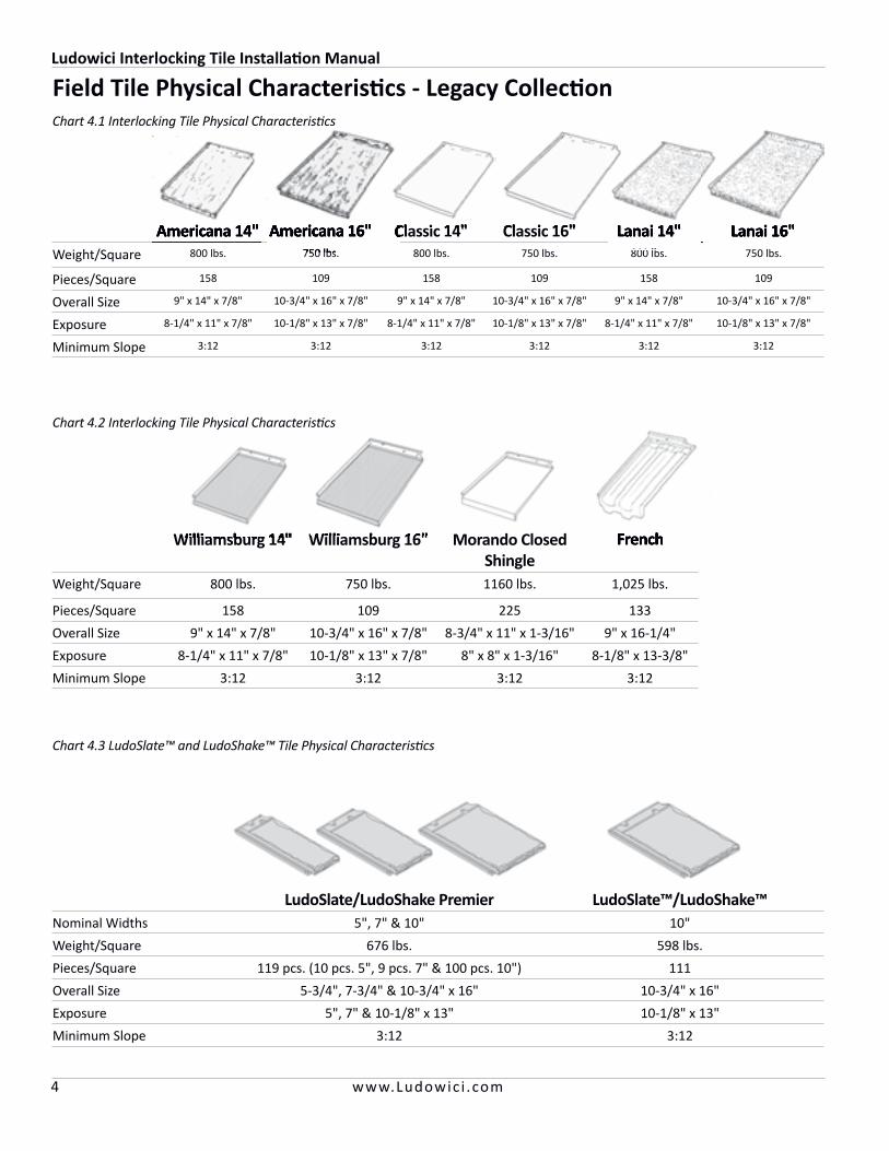
Field Tile Physical Characteristics - Legacy Collection
Americana 14" Americana 16" Classic 14" Classic 16" Lanai 14" Lanai 16"Weight/Square 800 lbs. 750 lbs. 800 lbs. 750 lbs. 800 lbs. 750 lbs.
Pieces/Square 158 109 158 109 158 109
Overall Size 9" x 14" x 7/8" 10-3/4" x 16" x 7/8" 9" x 14" x 7/8" 10-3/4" x 16" x 7/8" 9" x 14" x 7/8" 10-3/4" x 16" x 7/8"
Exposure 8-1/4" x 11" x 7/8" 10-1/8" x 13" x 7/8" 8-1/4" x 11" x 7/8" 10-1/8" x 13" x 7/8" 8-1/4" x 11" x 7/8" 10-1/8" x 13" x 7/8"
Minimum Slope 3:12 3:12 3:12 3:12 3:12 3:12
Williamsburg 14" Williamsburg 16" Morando Closed Shingle
French
Weight/Square 800 lbs. 750 lbs. 1160 lbs. 1,025 lbs.
Pieces/Square 158 109 225 133
Overall Size 9" x 14" x 7/8" 10-3/4" x 16" x 7/8" 8-3/4" x 11" x 1-3/16" 9" x 16-1/4"
Exposure 8-1/4" x 11" x 7/8" 10-1/8" x 13" x 7/8" 8" x 8" x 1-3/16" 8-1/8" x 13-3/8"
Minimum Slope 3:12 3:12 3:12 3:12
LudoSlate/LudoShake Premier LudoSlate™/LudoShake™Nominal Widths 5", 7" & 10" 10"
Weight/Square 676 lbs. 598 lbs.
Pieces/Square 119 pcs. (10 pcs. 5", 9 pcs. 7" & 100 pcs. 10") 111
Overall Size 5-3/4", 7-3/4" & 10-3/4" x 16" 10-3/4" x 16"
Exposure 5", 7" & 10-1/8" x 13" 10-1/8" x 13"
Minimum Slope 3:12 3:12
Americana 14" Americana 16" Classic 14"750 lbs.
Classic 14"Classic 14" Classic 16" Lanai 14"800 lbs.
Lanai 14" Lanai 16"
Williamsburg 14" Williamsburg 16" French
Chart 4.1 Interlocking Tile Physical Characteristics
Chart 4.2 Interlocking Tile Physical Characteristics
Chart 4.3 LudoSlate™ and LudoShake™ Tile Physical Characteristics
Ludowici Interlocking Tile Installation Manual
5www.Ludowic i .com
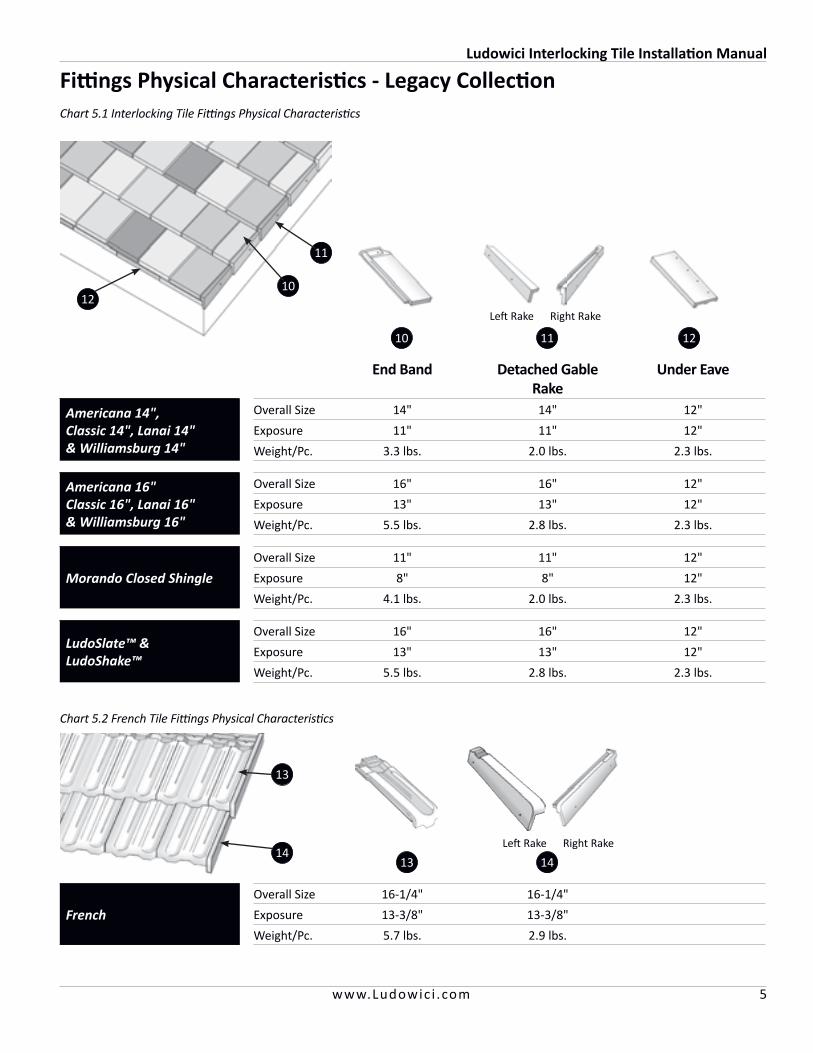
Fittings Physical Characteristics - Legacy Collection
10
11
Left Rake Right Rake
121110
End Band Detached Gable Rake
Under Eave
Americana 14",Classic 14", Lanai 14" & Williamsburg 14"
Overall Size 14" 14" 12"
Exposure 11" 11" 12"
Weight/Pc. 3.3 lbs. 2.0 lbs. 2.3 lbs.
Americana 16"Classic 16", Lanai 16"& Williamsburg 16"
Overall Size 16" 16" 12"
Exposure 13" 13" 12"
Weight/Pc. 5.5 lbs. 2.8 lbs. 2.3 lbs.
Morando Closed Shingle
Overall Size 11" 11" 12"
Exposure 8" 8" 12"
Weight/Pc. 4.1 lbs. 2.0 lbs. 2.3 lbs.
LudoSlate™ &LudoShake™
Overall Size 16" 16" 12"
Exposure 13" 13" 12"
Weight/Pc. 5.5 lbs. 2.8 lbs. 2.3 lbs.
French
Overall Size 16-1/4" 16-1/4"
Exposure 13-3/8" 13-3/8"
Weight/Pc. 5.7 lbs. 2.9 lbs.
13 14
12
Left Rake Right Rake
13
14
Chart 5.1 Interlocking Tile Fittings Physical Characteristics
Chart 5.2 French Tile Fittings Physical Characteristics
Ludowici Interlocking Tile Installation Manual
6 www.Ludowic i .com
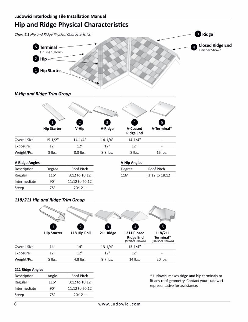
4 Closed Ridge EndFinisher Shown
Ridge
TerminalFinisher Shown
Hip Starter1
2
5
3
Hip and Ridge Physical Characteristics
V-Hip and Ridge Trim Group
1 2 3 4 5
Hip Starter V-Hip V-Ridge V-CLosed Ridge End
V-Terminal*
Overall Size 15-1/2" 14-1/4" 14-1/4" 14-1/4" -
Exposure 12" 12" 12" 12" -
Weight/Pc. 8 lbs. 8.8 lbs. 8.8 lbs. 8 lbs. 15 lbs.
V-Ridge Angles V-Hip Angles
Description Degree Roof Pitch Degree Roof Pitch
Regular 116° 3:12 to 10:12 116° 3:12 to 18:12
Intermediate 90° 11:12 to 20:12
Steep 75° 20:12 +
118/211 Hip and Ridge Trim Group
1 2 3 4 5
Hip Starter 118 Hip Roll 211 Ridge 211 Closed Ridge End
(Starter Shown)
118/211 Terminal*
(Finisher Shown)
Overall Size 14" 14" 13-1/4" 13-1/4" -
Exposure 12" 12" 12" 12" -
Weight/Pc. 5 lbs. 4.8 lbs. 9.7 lbs. 14 lbs. 20 lbs.
211 Ridge Angles
Description Angle Roof Pitch * Ludowici makes ridge and hip terminals to fit any roof geometry. Contact your Ludowici representative for assistance.
Regular 116° 3:12 to 10:12
Intermediate 90° 11:12 to 20:12
Steep 75° 20:12 +
Hip
Chart 6.1 Hip and Ridge Physical Characteristics

Ludowici Interlocking Tile Installation Manual
7www.Ludowic i .com
Circular Cover Hip and Ridge Trim Group
1 2 3 4 5 5
CC-Hip Starter CC-Hip CC-Ridge CC-Closed Ridge End
CC-Terminal*
CC-High Bump Terminal*
Overall Size 15-1/2" 16" 16" 14-1/4" - -
Exposure 12" 13" 13" 12" - -
Weight/Pc. 9 lbs. 5.8 lbs. 5.8 lbs. 9.8 lbs. 15 lbs. 25 lbs.
102/206 Hip and Ridge Trim Group
1 2 3 4 5 5 4
152 Hip Starter 102 Hip Roll 206 Ridge 206 Closed Ridge End
(Starter Shown)
102/206 Terminal*
(Starter Shown)
405 High Bump Terminal*
(Finisher Shown)
406 High Bump Gable Terminal
(Finisher Shown)
Overall Size 14" 14" 13-1/4" 13-1/4" - - -
Exposure 12" 12" 12" 12" - - -
Weight/Pc. 6.3 lbs. 6.2 lbs. 11.5 lbs. 18 lbs. 17 lbs. 35 lbs. 30 lbs.
* Ludowici makes ridge and hip terminals to fit any roof geometry. Contact your Ludowici representative for assistance.
Chart 7.1 Hip and Ridge Physical Characteristics

Ludowici Interlocking Tile Installation Manual
8 www.Ludowic i .com
Field Tile Physical Characteristics - Bear Creek Collection
Lexington Slate®Nominal Widths 7", 10-1/2" & 14"
Weight/Square 783 lbs.
Pieces/Square 152 pcs. (110 pcs. Full, 28 pcs. 10-2/3" & 14 pcs. 7")
Overall Size 7-5/8" x 10-1/2" x 1", 11-3/8" x 10-1/2" x 1", 14-3/4" x 10-1/2" x 1"
Exposure 7 x 7-1/2", 10-1/2" x 7-1/2", 14" x 7-1/2"
Minimum Slope 3:12
Century Shake®Nominal Widths 5", 6-2/3" & 10"
Weight/Square 679 lbs.
Pieces/Square 141 pcs. (100 pcs. Full, 28 pcs. 6-2/3" & 14 pcs. 5")
Overall Size 5-1/2" x 14-1/2" x 1", 7-3/16" x 14-1/2" x 1", 10-1/2" x 14-1/2" x 1"
Exposure 5 x 11-1/2", 6-11/16" x 11-1/2", 10" x 11-1/2"
Minimum Slope 3:12
Chart 8.1 Lexington Slate® Tile Physical Characteristics
Chart 8.2 Century Shake® Tile Physical Characteristics
*Note: The locking channel for Lexington Slate® is on the right side of the tile and installation will be left to right.
Ludowici Interlocking Tile Installation Manual
9www.Ludowic i .com
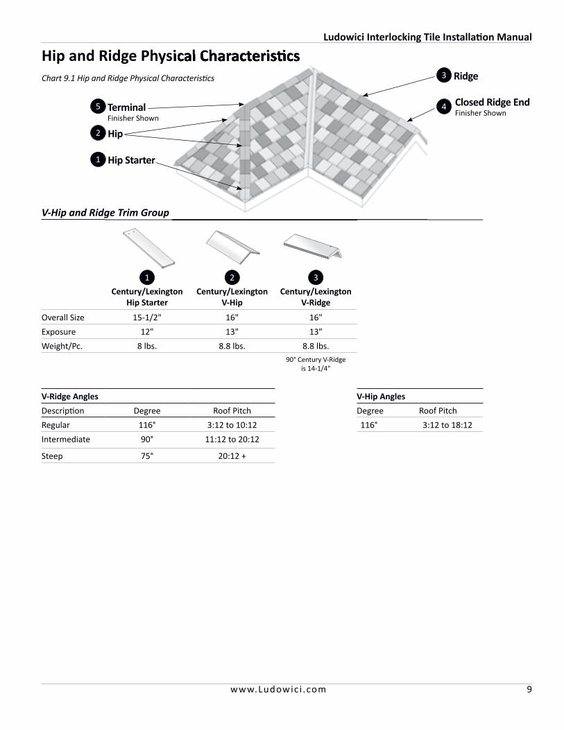
4 Closed Ridge EndFinisher Shown
Ridge
TerminalFinisher Shown
Hip Starter1
2
5
3
Hip and Ridge Physical Characteristics
V-Hip and Ridge Trim Group
1 2 3
Century/Lexington Hip Starter
Century/Lexington V-Hip
Century/Lexington V-Ridge
Overall Size 15-1/2" 16" 16"
Exposure 12" 13" 13"
Weight/Pc. 8 lbs. 8.8 lbs. 8.8 lbs.90° Century V-Ridge
is 14-1/4"
V-Ridge Angles V-Hip Angles
Description Degree Roof Pitch Degree Roof Pitch
Regular 116° 3:12 to 10:12 116° 3:12 to 18:12
Intermediate 90° 11:12 to 20:12
Steep 75° 20:12 +
Hip
Hip and Ridge Physical CharacteristicsChart 9.1 Hip and Ridge Physical Characteristics
Ludowici Interlocking Tile Installation Manual
10 www.Ludowic i .com
Roof DeckA design standard for roofing decks is to have a maximum deflection of L/240 between supports. A deck will be exposed to live and dead loads. A live load is one that will only be exerting pressure on the roof deck for a short time. Example; Snow or wind loads. A dead load is one that will exert a constant pressure to the roof deck; i.e., underlayments, tile and battens.
Fastener Pullout Resistance: Minimum average fastener pullout resistance for clay roofing tile is 180 lbs. with no single value less than 170 lbs. Greater pullout values may be required depending upon the predicted aerodynamic moment expected for the tile shape, building shape and the proximity to the coastline. An engineer should be consulted to assure local building code compliance.
For Board Plank Deck: Use well-seasoned plank board (1" full thickness, maximum 6" nominal width) that is not prone to warping, cupping or twisting.
For Plywood Deck: APA rated plywood is required for a minimum of 3/4" thick wood decking and must be rated for structural use as roof sheathing. The expansion crack between panels shall be at least 1/16" but no greater than 1/8". H-clips are to be used when rafters are spaced greater than 16" on center to hold the side joints of the plywood together between supports. Unsupported end joints must be blocked.
Nailable Concrete Decks: Nailable concrete decks over time may lose their plastic nature, which allows direct nailing. For old decking material, a pullout test should be performed to determine the usefulness of the deck and the appropriate fastener. An engineer should be consulted to assure local building code compliance.
Non-Nailable Concrete Decks: For concrete decks that will not accept direct nailing, nailer boards are required. Attachment strips that allow the tile to be fastened to them should be pressure treated wood. These may be a board and batten system or pressure treated wood strips. Other means
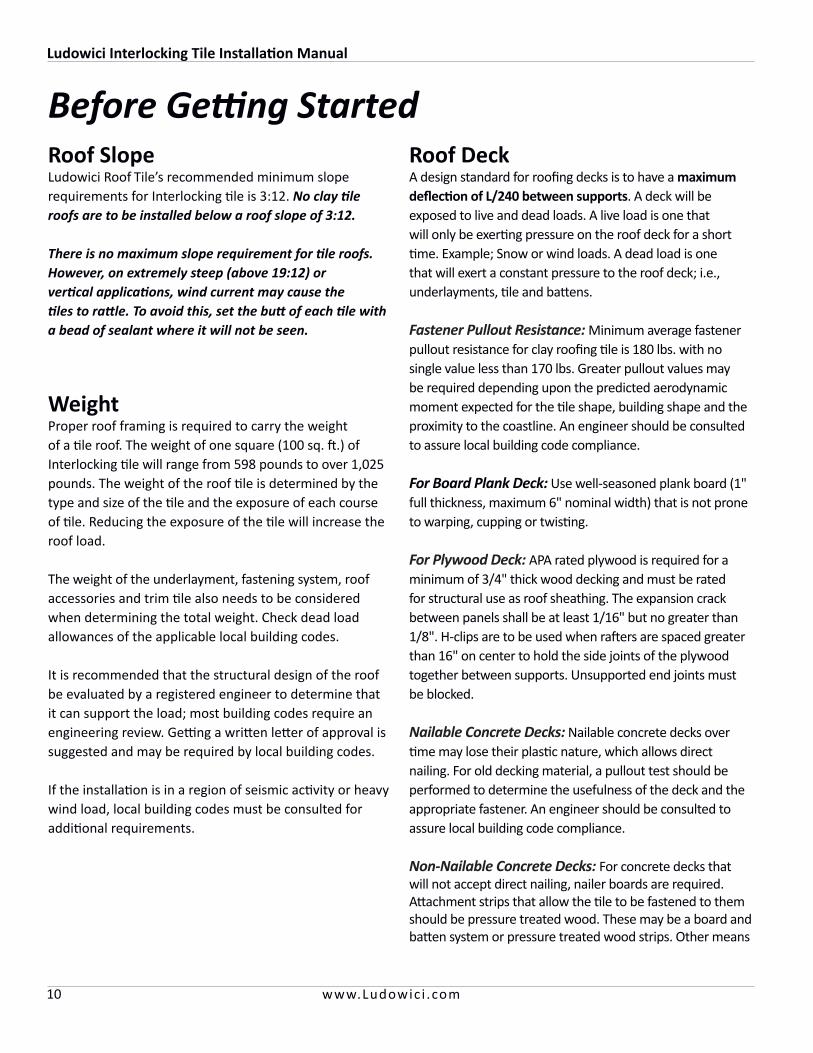
WeightProper roof framing is required to carry the weight of a tile roof. The weight of one square (100 sq. ft.) of Interlocking tile will range from 598 pounds to over 1,025 pounds. The weight of the roof tile is determined by the type and size of the tile and the exposure of each course of tile. Reducing the exposure of the tile will increase the roof load.
The weight of the underlayment, fastening system, roof accessories and trim tile also needs to be considered when determining the total weight. Check dead load allowances of the applicable local building codes.
It is recommended that the structural design of the roof be evaluated by a registered engineer to determine that it can support the load; most building codes require an engineering review. Getting a written letter of approval is suggested and may be required by local building codes.
If the installation is in a region of seismic activity or heavy wind load, local building codes must be consulted for additional requirements.
Roof Slope Ludowici Roof Tile’s recommended minimum slope requirements for Interlocking tile is 3:12. No clay tile roofs are to be installed below a roof slope of 3:12.
There is no maximum slope requirement for tile roofs. However, on extremely steep (above 19:12) or vertical applications, wind current may cause the tiles to rattle. To avoid this, set the butt of each tile with a bead of sealant where it will not be seen.
Before Getting Started
Ludowici Interlocking Tile Installation Manual
11www.Ludowic i .com
of attaching tile to a concrete deck include wire-tie systems, foam adhesive and expanding nail-in anchors.
NOTE: Ludowici does not recommend applying tile over spaced board sheathing or open battens.
Underlayment Most problems with water-shedding roof installations occur from water that migrates through the joints of the tiles through capillary action, wind driven rain and runoff or ice damming. Because of this possibility, the underlayment is critical to the success of the roof. It is the architect or building owner’s responsibility to select an underlayment product that is suitable to specific location, climate, roof pitch and attic ventilation. When selecting an underlayment remember that Ludowici roof tiles are expected to last over 75 years so the underlayment should be of a comparable lifespan and quality.
Ludowici recommends the following for minimum underlayment:
• All decks shall be covered with two layers of No. 30# asphalt-impregnated roofing felt or one layer of No. 43# coated base sheet or one layer of Ice and Water Shield.
NOTE: When using non-breathing Ice and Water Shield underlayments to cover the entire roof, the attic space MUST be properly ventilated to prevent moisture buildup.
• All hips, valleys, rakes and ridges shall be covered with a waterproof underlayment, example; Ice and Water Shield or two layers of No. 43# coated base sheet.
• For proper ice dam protection a layer of Ice and Water Shield underlayment should be installed from the eave to a point 24" beyond the inside of the exterior wall. See page 14 for more information on ice dam protection.
NOTE: Roofing felt should meet or exceed ASTM standards D226/D2626. Self adhered Modified should meet or exceed ASTM D1970.
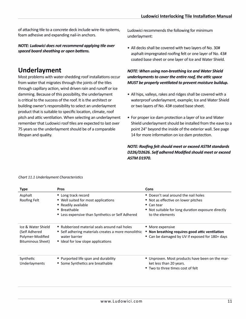
Type Pros Cons
Asphalt Roofing Felt
• Long track record• Well suited for most applications• Readily available• Breathable• Less expensive than Synthetics or Self Adhered
• Doesn’t seal around the nail holes• Not as effective on lower pitches• Can tear• Not suitable for long duration exposure directly
to the elements
Ice & Water Shield (Self Adhered Polymer-Modified Bituminous Sheet)
• Rubberized material seals around nail holes• Self adhering materials creates a more monolithic
water barrier• Ideal for low slope applications
• More expensive• Non breathing requires good attic ventilation• Can be damaged by UV if exposed for 180+ days
Synthetic Underlayments
• Purported life span and durability• Some Synthetics are breathable
• Unproven. Most products have been on the mar-ket less than 20 years.
• Two to three times cost of felt
Chart 11.1 Underlayment Characteristics
Ludowici Interlocking Tile Installation Manual
12 www.Ludowic i .com
Fastening MethodsAttachment requirements and fastener length are referenced in Chart 13.1
Nails or Screws: Nails are the most commonly used fastener for attaching clay tiles. Nails for tiles and cleats must be copper or stainless steel, 11 gauge minimum, .285"-.312" head minimum and proper length to give good penetration. Screws must be stainless steel or brass, #8 or #9, with a minimum .285"-.312" diameter head.
NOTE: The use of Galvanized, Ceramic coated or any other fastener not mentioned above is not acceptable to Ludowici. All components of the roof should have an expected lifespan of 75+ years.
NOTE: Each flat Interlocking field tile is provided with (2) two fastening nail holes and French field tile with (1) one. When installing field tiles, care should be taken to fasten each tile with nails or screws in every provided fastening hole.
• For a plywood deck, use ring shank copper nails of the specified length to assure good penetration through under side of deck (see Chart 13.1).
• For board plank deck, use smooth shank copper nails of the specified length. Fasteners should penetrate deck board 3/4". Do not penetrate underside of deck.
• For gypsum plank or nailable concrete deck, use stainless steel or silicon bronze screw shank nails of length to penetrate half to three-quarters the thickness of the deck. Never penetrate underside of deck.
• When insulation is applied over the deck, observe the following:
- Minimum slope 3:12 - The tile can be nailed through underlayment and insulation into the deck with a sufficient length fastener.
- On 6:12 or greater, a tile-tie system should be used.
• For metal decks, use sheet metal screws and the proper mastic.
• For fibrous cement decks, use a tile-tie system.
NOTE: When using stainless steel screws, tile replacement will require the use of a hack saw to remove the screws. A slate ripper may be used with copper or brass fasteners.
Wire: On non-nailable surfaces or some insulated decks or where fastening through the metal flashing needs to be avoided or if underlayment cannot be penetrated, such as special low slope applications, wire and strapping systems are sometimes used. Wire must be 13 gauge stainless steel or 10 gauge solid copper, with or without insulation. Wire-tieing is also usually specified in areas prone to earthquakes. Consult Newportfastener.com for specific design and installation assistance.
Clips: Wind clips are often specified and/or required in high wind and seismic areas. They aid in holding the tiles in place and reduce stress at the preliminary fastening point. Refer to local building codes in such areas.
NOTE: In high wind regions, install each tile with #8 or #9 stainless steel or brass flathead Phillips or square drive screws and/or use a hurricane clip. Hurricane clips and sealants may be required by the local building codes.
Bedding Tile: Where freeze-thaw cycles are not an issue, tile may be laid in a full or partial bed of mortar. This method is best used in combination with other means of attachment.
Foam Adhesive: This method of application is approved for use in Sun Belt non freeze-thaw areas and is being tested for use in other areas. Refer to local building codes. Do not use single part foam systems with Ludowici tile. Only two part systems such as Polyset® from Polyfoam are acceptable. Visit Polyfoam.cc for design and installation assistance.
IMPORTANT:Before application of Ludowici tiles in Alpine conditions, plans must be submitted to the Ludowici Technical Department for approval. Ludowici will not assume liability or responsibility for damage caused by the application of clay tiles in Alpine conditions.
Ludowici Interlocking Tile Installation Manual
13www.Ludowic i .com
Americana, Classic, Lanai, Williamsburg, Closed Shingle, LudoSlate & LudoShake Substrate Field Tile Hip Ridge Quik-Tach™ Bracket Hurricane Clip
Boards 1-3/4" 2" 2-1/2" Type C 1-1/4"
3/4" Plywood 2" 2" 2-1/2" Type C 1-1/4"
Chart 13.1 Attachment Requirements
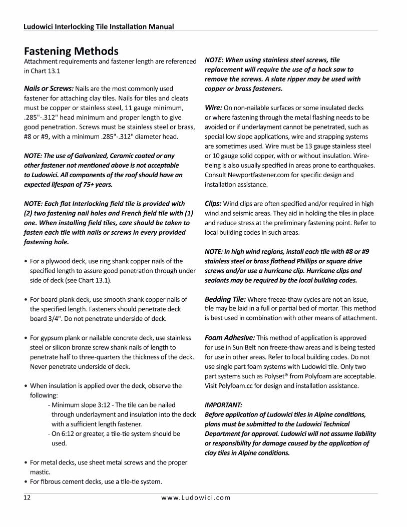
Figure 13.1 Proper Nailing Techniques for Plywood Decks
Properly Driven Improperly Driven
Driven Straight, Good Penetration
Not Driven Enough, Inadequate Deck Penetration
Driven Too Tightly, Cracking or Breaking the Tile
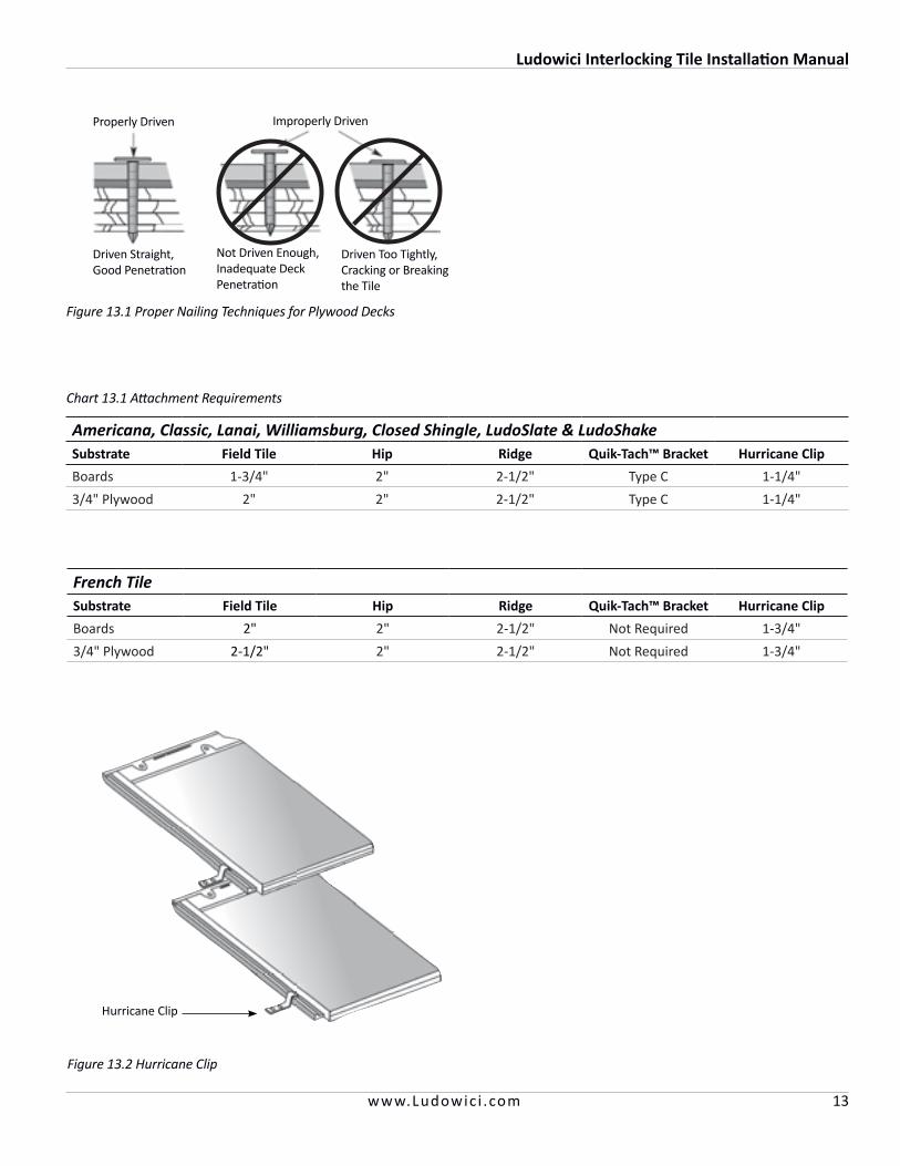
French TileSubstrate Field Tile Hip Ridge Quik-Tach™ Bracket Hurricane Clip
Boards 2" 2" 2-1/2" Not Required 1-3/4"
3/4" Plywood 2-1/2" 2" 2-1/2" Not Required 1-3/4"
Figure 13.2 Hurricane Clip
Hurricane Clip
Ludowici Interlocking Tile Installation Manual
14 www.Ludowic i .com
Assemble All Tools and SuppliesThe following tools are needed for basic installation of clay roofs:
• Safety equipment as required by OSHA and other local and state agencies
• Rule or tape • Mason’s trowel and bucket• Chalk line and chalk • 4" diamond-tipped turbo blade on angle grinder• Claw hammer • Protective eye wear/dust mask• Chipping hammer • Caulking gun• Felt knife• Sheet metal shears• Roof jacks• Slate ripper• Segmented diamond blade (8"to 10" diameter) • Wet tub saw• Tile nippers• Marking pencil • Sharp steel punch• Battery-operated, clutch-driven drill
(with extra batteries) • Carbide spear point glass drill bits• Small steel roller
IMPORTANT: All roof work can be hazardous. Safety requirements are spelled out by OSHA and individual state Occupational Safety and Health Administration regulations. It is the responsibility of the installer to take all necessary precautions. Contact the Occupational Safety and Health Administration for complete information.
IMPORTANT: All roofing components should be selected to be compatible with the long service life of a Ludowici roof.
In addition to tools, the following materials are needed:
• Flashing: use a minimum weight of 16 oz. copper, at least 24" wide with 1/4" edge turned over and fastened with cleats for valleys. Under special circumstances, such as unusual exposure to high wind or heavy snow, this flashing weight should be increased. Lighter weight copper flashings are undesirable because they can puncture too easily and they will not provide the wear life required for a long-life roof system.
• Underlayment: two layers of No. 30# asphalt-impreg-nated roofing felt or one layer of No. 43# coated base sheet, doubled on rough surfaces, hips, valleys and ridges, or one layer of Ice and Water Shield.
• Roofing cement: roofing cement for gable rakes, hip rolls, ridges, stringers and other conditions should be non-running, heavy-body flashing cement composed of mineral ingredients to meet the requirements of ASTM D-4586.
• Cant strips, wood nailers and field tile nailer strips: all should be foundation grade wood.
• Mortar and mortar color to match tiles: Ludowici defines mortar as one part Portland cement and four parts sand (to ASTM specification C-270). Contact your local brick distributor to acquire colorant.
• Silicone sealant or adhesive: the recommended sealant for exposed caulking is Dow Corning® 790 Silicone Building Sealant™ or GE® SilProof™ (ASTM C-920, low modules). These sealants may be used as hidden adhesives. NP1 or other adhesives may be suitable as well; however, care should be taken to select for maximum durability and also for compatibility with adjacent materials. Some sealants are available in different colors to match tiles.
Getting Started

Ludowici Interlocking Tile Installation Manual
15www.Ludowic i .com
Inspecting the Deck• Ensure that the roof deck is clean, smooth and dry
before roof tiles are applied. • Verify that there is no significant delamination,
warpage, bowing or separation from the rafters or trusses. Check for deck rot.
• If deck is APA 3/4" rated plywood, check that panels are spaced approximately 1/16" to a maximum of 1/8" apart for expansion and H-clips are used between supports when the rafter spacing exceeds 16" O.C. Unsupported end joints must be blocked.
• Make repairs to the deck as necessary.
Installing the Underlayment Most problems with water-shedding roof installations oc-cur from water that migrates through the joints of the tiles through capillary action, wind-driven rain and runoff or ice damming. Because of this possibility, the underlayment is critical to the success of the roof.
At a minimum, all decks must be covered with two layers of No. 30# asphalt-impregnated roofing felt or one layer of No. 43# coated base sheet.
NOTE: Underlayment materials must be covered with tile as soon as possible to prevent degradation from exposure.
If wood cant strips and nailers are nailed directly to the deck, they must be covered with waterproof underlayment. If nailed on the underlayment, they should be pressure treated wood.
NOTE: All roofing underlayment materials should be carried 6" up all vertical surfaces.
For single layer of No. 43# coated base sheet: Lay base sheet parallel to eave. Side lap - 2" and end lap - 6".
Figure 15.1 Single Sheet Underlayment
Succeeding Courses of No. 43# Coated Base Sheet Underlayment to be 36" Wide (After Meeting Minimum Re-quirements for Ice Damming)
Backnail Sheets
Wood Deck
Plies of Ice and Water Shield Underlayment Mate-rial Installed Up to a Point 24" as Required Inside the Exterior Wall Line of Building to Provide an Ice Dam Protection Membrane
36"
36"
2"
NOTE: All dimensions are approximate
For Double Layers, follow these steps: First apply a starter sheet of 1 layer of Ice and Water Shield underlayment per manufacturer’s instructions.
Then completely cover the starter sheet with a full-width sheet of No. 43# roofing felt. Lap succeeding sheets 19" over the preceding sheets, leaving a 17" exposure (2" lap). End laps should be a minimum of 6" (see Figure 13.2).
Preparing the Roof
Plies of Ice and Water Shield Underlayment Mate-rial Installed Up to a Point 24" as Required Inside the Exterior Wall Line of Building to Provide an Ice Dam Protection Membrane
Wood DeckBacknail SheetsFirst and Succeeding Courses of Underlayment to be 36" Wide and Lapped 19"
Figure 15.2 Double Sheet Underlayment
NOTE: Prior to applying any roofing material, all con-tractor work above the roofline must be completed.
36" 17"
2" Side Lap
Ludowici Interlocking Tile Installation Manual
16 www.Ludowic i .com
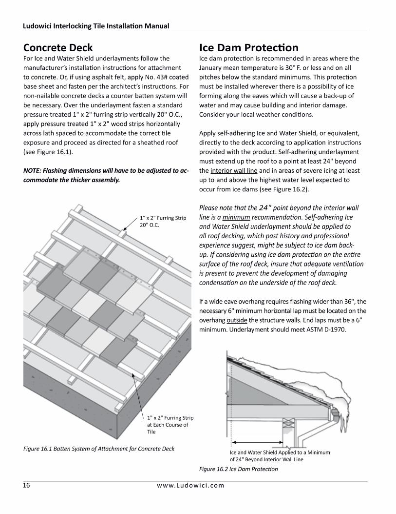
Ice Dam Protection Ice dam protection is recommended in areas where the January mean temperature is 30° F. or less and on all pitches below the standard minimums. This protection must be installed wherever there is a possibility of ice forming along the eaves which will cause a back-up of water and may cause building and interior damage. Consider your local weather conditions.
Apply self-adhering Ice and Water Shield, or equivalent, directly to the deck according to application instructions provided with the product. Self-adhering underlayment must extend up the roof to a point at least 24" beyond the interior wall line and in areas of severe icing at least up to and above the highest water level expected to occur from ice dams (see Figure 16.2).
Please note that the 24" point beyond the interior wall line is a minimum recommendation. Self-adhering Ice and Water Shield underlayment should be applied to all roof decking, which past history and professional experience suggest, might be subject to ice dam back-up. If considering using ice dam protection on the entire surface of the roof deck, insure that adequate ventilation is present to prevent the development of damaging condensation on the underside of the roof deck.
If a wide eave overhang requires flashing wider than 36", the necessary 6" minimum horizontal lap must be located on the overhang outside the structure walls. End laps must be a 6" minimum. Underlayment should meet ASTM D-1970.
Figure 16.2 Ice Dam Protection
Ice and Water Shield Applied to a Minimum of 24" Beyond Interior Wall Line
Concrete DeckFor Ice and Water Shield underlayments follow the manufacturer’s installation instructions for attachment to concrete. Or, if using asphalt felt, apply No. 43# coated base sheet and fasten per the architect’s instructions. For non-nailable concrete decks a counter batten system will be necessary. Over the underlayment fasten a standard pressure treated 1" x 2" furring strip vertically 20" O.C., apply pressure treated 1" x 2" wood strips horizontally across lath spaced to accommodate the correct tile exposure and proceed as directed for a sheathed roof (see Figure 16.1).
NOTE: Flashing dimensions will have to be adjusted to ac-commodate the thicker assembly.
Figure 16.1 Batten System of Attachment for Concrete Deck
1" x 2" Furring Strip 20" O.C.
1" x 2" Furring Strip at Each Course of Tile
Ludowici Interlocking Tile Installation Manual
17www.Ludowic i .com
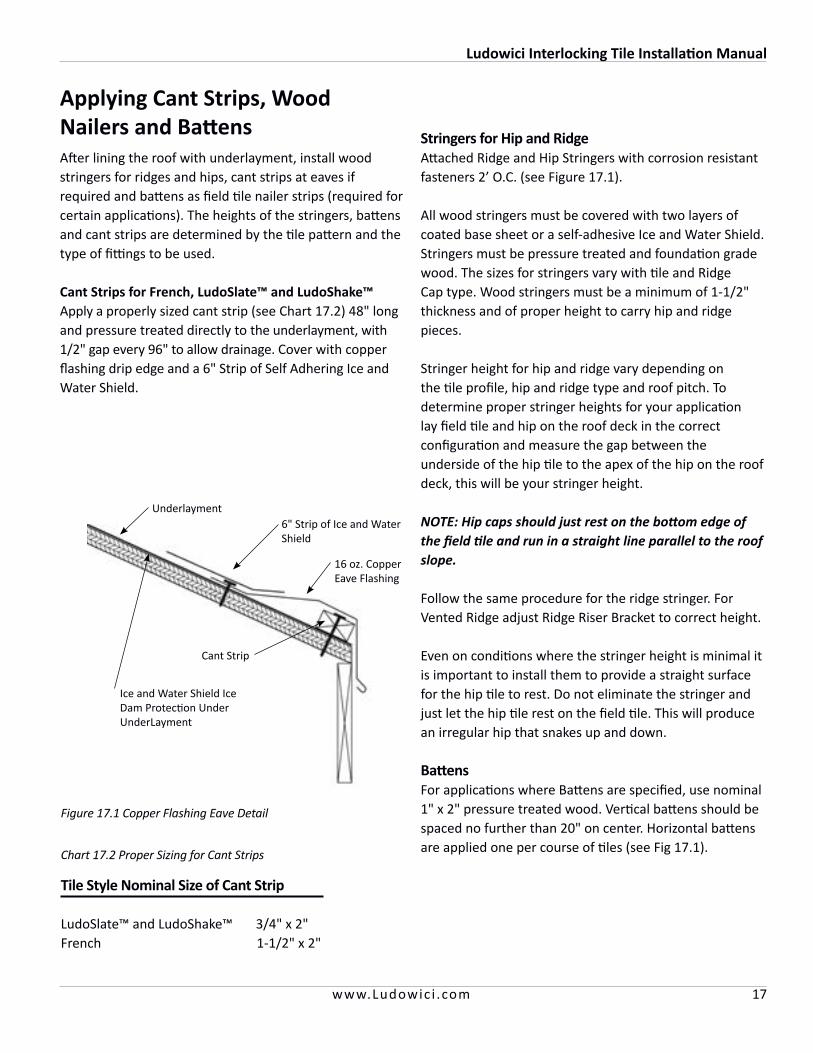
Tile Style Nominal Size of Cant Strip LudoSlate™ and LudoShake™ 3/4" x 2"French 1-1/2" x 2"
Applying Cant Strips, Wood Nailers and BattensAfter lining the roof with underlayment, install wood stringers for ridges and hips, cant strips at eaves if required and battens as field tile nailer strips (required for certain applications). The heights of the stringers, battens and cant strips are determined by the tile pattern and the type of fittings to be used.
Cant Strips for French, LudoSlate™ and LudoShake™Apply a properly sized cant strip (see Chart 17.2) 48" long and pressure treated directly to the underlayment, with 1/2" gap every 96" to allow drainage. Cover with copper flashing drip edge and a 6" Strip of Self Adhering Ice and Water Shield.
Underlayment6" Strip of Ice and Water Shield
16 oz. Copper Eave Flashing
Cant Strip
Figure 17.1 Copper Flashing Eave Detail
Stringers for Hip and RidgeAttached Ridge and Hip Stringers with corrosion resistant fasteners 2’ O.C. (see Figure 17.1).
All wood stringers must be covered with two layers of coated base sheet or a self-adhesive Ice and Water Shield. Stringers must be pressure treated and foundation grade wood. The sizes for stringers vary with tile and Ridge Cap type. Wood stringers must be a minimum of 1-1/2" thickness and of proper height to carry hip and ridge pieces.
Stringer height for hip and ridge vary depending on the tile profile, hip and ridge type and roof pitch. To determine proper stringer heights for your application lay field tile and hip on the roof deck in the correct configuration and measure the gap between the underside of the hip tile to the apex of the hip on the roof deck, this will be your stringer height.
NOTE: Hip caps should just rest on the bottom edge of the field tile and run in a straight line parallel to the roof slope.
Follow the same procedure for the ridge stringer. For Vented Ridge adjust Ridge Riser Bracket to correct height.
Even on conditions where the stringer height is minimal it is important to install them to provide a straight surface for the hip tile to rest. Do not eliminate the stringer and just let the hip tile rest on the field tile. This will produce an irregular hip that snakes up and down.
BattensFor applications where Battens are specified, use nominal 1" x 2" pressure treated wood. Vertical battens should be spaced no further than 20" on center. Horizontal battens are applied one per course of tiles (see Fig 17.1).Chart 17.2 Proper Sizing for Cant Strips
Ice and Water Shield Ice Dam Protection Under UnderLayment
Ludowici Interlocking Tile Installation Manual
18 www.Ludowic i .com
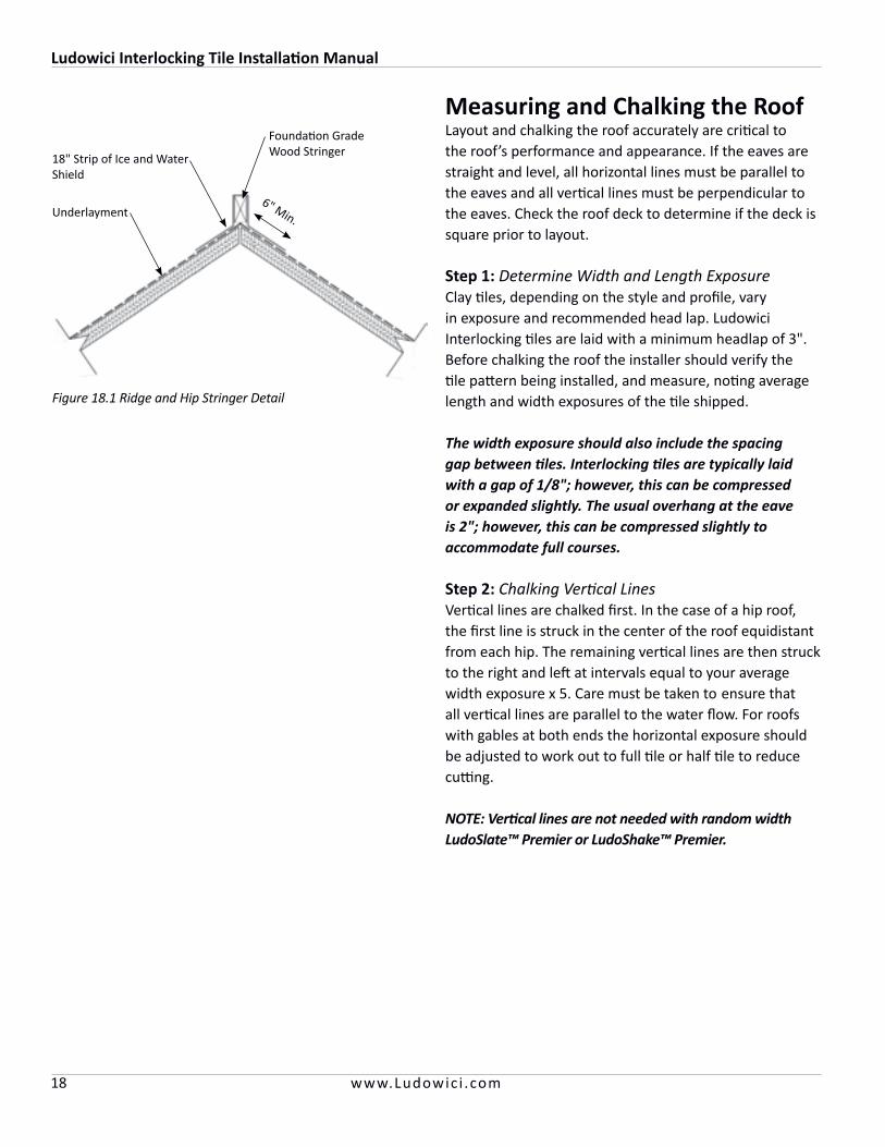
Measuring and Chalking the Roof Layout and chalking the roof accurately are critical to the roof’s performance and appearance. If the eaves are straight and level, all horizontal lines must be parallel to the eaves and all vertical lines must be perpendicular to the eaves. Check the roof deck to determine if the deck is square prior to layout.
Step 1: Determine Width and Length Exposure Clay tiles, depending on the style and profile, vary in exposure and recommended head lap. Ludowici Interlocking tiles are laid with a minimum headlap of 3". Before chalking the roof the installer should verify the tile pattern being installed, and measure, noting average length and width exposures of the tile shipped.
The width exposure should also include the spacing gap between tiles. Interlocking tiles are typically laid with a gap of 1/8"; however, this can be compressed or expanded slightly. The usual overhang at the eave is 2"; however, this can be compressed slightly to accommodate full courses.
Step 2: Chalking Vertical Lines Vertical lines are chalked first. In the case of a hip roof, the first line is struck in the center of the roof equidistant from each hip. The remaining vertical lines are then struck to the right and left at intervals equal to your average width exposure x 5. Care must be taken to ensure that all vertical lines are parallel to the water flow. For roofs with gables at both ends the horizontal exposure should be adjusted to work out to full tile or half tile to reduce cutting.
NOTE: Vertical lines are not needed with random width LudoSlate™ Premier or LudoShake™ Premier.
Figure 18.1 Ridge and Hip Stringer Detail
Underlayment
18" Strip of Ice and Water Shield
Foundation Grade Wood Stringer
6" Min.
Ludowici Interlocking Tile Installation Manual
19www.Ludowic i .com
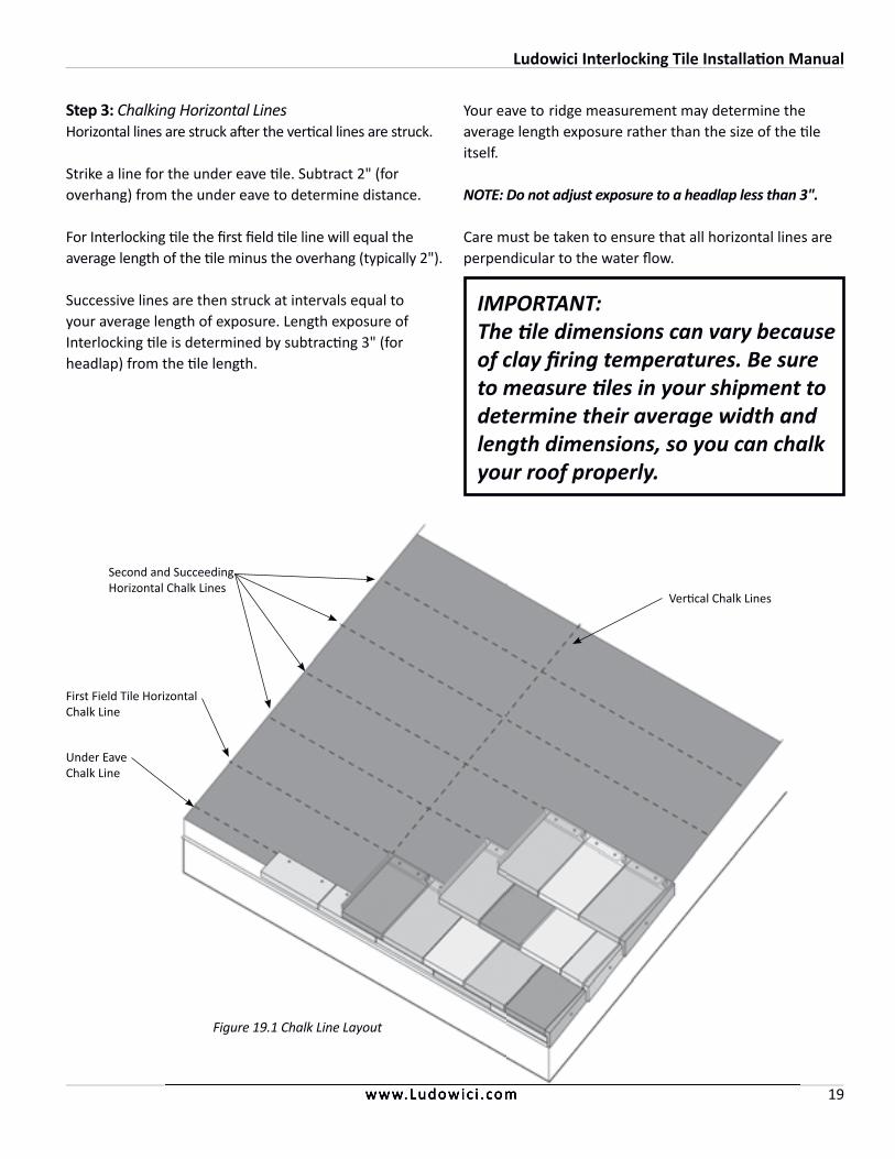
Step 3: Chalking Horizontal Lines Horizontal lines are struck after the vertical lines are struck.
Strike a line for the under eave tile. Subtract 2" (for overhang) from the under eave to determine distance.
For Interlocking tile the first field tile line will equal the average length of the tile minus the overhang (typically 2").
Successive lines are then struck at intervals equal to your average length of exposure. Length exposure of Interlocking tile is determined by subtracting 3" (for headlap) from the tile length.
IMPORTANT:The tile dimensions can vary because of clay firing temperatures. Be sure to measure tiles in your shipment to determine their average width and length dimensions, so you can chalk your roof properly.
www.Ludowic i .com
Your eave to ridge measurement may determine the average length exposure rather than the size of the tile itself.
NOTE: Do not adjust exposure to a headlap less than 3".
Care must be taken to ensure that all horizontal lines are perpendicular to the water flow.
Figure 19.1 Chalk Line Layout
Vertical Chalk Lines
First Field Tile Horizontal Chalk Line
Second and Succeeding Horizontal Chalk Lines
Under Eave Chalk Line
Ludowici Interlocking Tile Installation Manual
20 www.Ludowic i .com
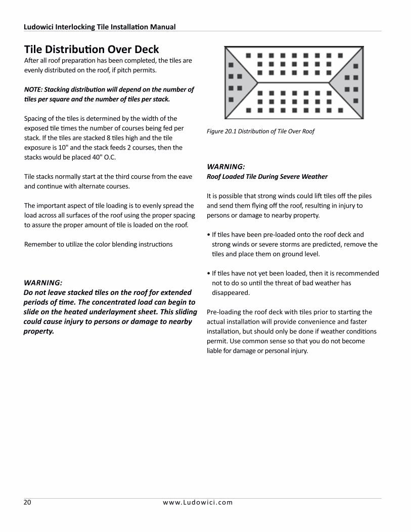
Tile Distribution Over DeckAfter all roof preparation has been completed, the tiles are evenly distributed on the roof, if pitch permits.
NOTE: Stacking distribution will depend on the number of tiles per square and the number of tiles per stack.
Spacing of the tiles is determined by the width of the exposed tile times the number of courses being fed per stack. If the tiles are stacked 8 tiles high and the tile exposure is 10" and the stack feeds 2 courses, then the stacks would be placed 40" O.C.
Tile stacks normally start at the third course from the eave and continue with alternate courses.
The important aspect of tile loading is to evenly spread the load across all surfaces of the roof using the proper spacing to assure the proper amount of tile is loaded on the roof.
Remember to utilize the color blending instructions
WARNING: Roof Loaded Tile During Severe Weather
It is possible that strong winds could lift tiles off the piles and send them flying off the roof, resulting in injury to persons or damage to nearby property.
• If tiles have been pre-loaded onto the roof deck and strong winds or severe storms are predicted, remove the tiles and place them on ground level.
• If tiles have not yet been loaded, then it is recommended not to do so until the threat of bad weather has disappeared.
Pre-loading the roof deck with tiles prior to starting the actual installation will provide convenience and faster installation, but should only be done if weather conditions permit. Use common sense so that you do not become liable for damage or personal injury.
WARNING: Do not leave stacked tiles on the roof for extended periods of time. The concentrated load can begin to slide on the heated underlayment sheet. This sliding could cause injury to persons or damage to nearby property.
Figure 20.1 Distribution of Tile Over Roof
Ludowici Interlocking Tile Installation Manual
21www.Ludowic i .com
Cutting, Notching and Drilling
Cutting NOTE: Unnecessary cutting and drilling time can add substantial cost to the job. Carefully consider tile layout before starting the work to minimize cutting and drilling.
Tiles should be cut wet on the job with a masonry or tile saw equipped with a diamond blade. Segmented blades will be the most efficient. Slight surface chipping will occur during the cutting operation. The sliding saw table and tub should be as large as possible to accommodate cutting the tiles diagonally.
Ludowici tiles are extremely hard, which provides the tiles with low moisture absorption and long life. Dry cutting techniques used on softer tile products will not work as fast with Ludowici’s hard tile. Dry cutting with a good segmented “turbo” diamond blade is possible. Best results have been obtained using a 4" diamond tipped segmented blade mounted on a small right angle grinder motor.
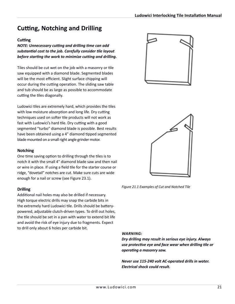
NotchingOne time saving option to drilling through the tiles is to notch it with the small 4" diamond blade saw and then nail or wire in place. If using a field tile for the starter course or ridge, “dovetail” notches are cut. Make sure cuts are wide enough for a nail or screw (see Figure 23.1).
DrillingAdditional nail holes may also be drilled if necessary. High torque electric drills may snap the carbide bits in the extremely hard Ludowici tile. Drills should be battery-powered, adjustable clutch-driven types. To drill out holes, the tile should be set in a pan with water to extend bit life and avoid the risk of eye injury due to fragments. Expect to drill only about 6 holes per carbide bit.
WARNING: Dry drilling may result in serious eye injury. Always use protective eye and face wear when drilling tile or operating a masonry saw.
Never use 115-240 volt AC-operated drills in water. Electrical shock could result.
Figure 21.1 Examples of Cut and Notched Tile
Ludowici Interlocking Tile Installation Manual
22 www.Ludowic i .com
Color Blending with Different Color TileBlending different tile colors can provide a unique and aesthetically pleasing roof.
Make a drawing to detail the layout and to help determine the proper number of tiles of each color.
In order to maintain the correct color blend, pull tiles from the different pallets of each color. Premix these piles in the desired percentage and load the roof one square at a time. This will provide even distribution. Additional care should be taken by the roofer laying the tiles to avoid clumping of a single color or range.
After the installation of about 75-100 tiles, the roof should be inspected from the ground at a distance greater than 40 feet to determine that there are no streaks or blotches. To ensure a good color blend, this inspection must be done at regular intervals.
NOTE: It may be helpful to lay the tile blend out on the ground so the installer has a visual example. Make one person responsible for the ongoing and end result of the blending.
Blending
Blending is one of the most important aspects of correctly installing a Ludowici tile roof.
Whether installing a single color or multiple colors ALL LUDOWICI ROOFS MUST BE BLENDED.
Colors within a given shipment of Ludowici clay roof tile will vary slightly due to subtle changes in clay composition and kiln firing temperatures. Such color variances are not a defect but a natural desirable feature that gives roofs depth and character.
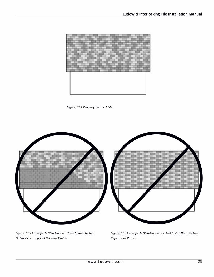
Unless the architect or owner specifies a pattern, there should be no visible pattern or hot spots on the roof.
Ludowici does not pre-blend the tile. It is the roofers responsibility to evaluate the tiles for color shade and range and then properly blend them to achieve a harmonious color roof without blotches, hotspots or patterns.
The person responsible for the blending of the shades of color should randomly select tiles from at least four different pallets.
After the installation of about 75-100 tiles, the roof should be inspected from the ground at a distance greater than 40 feet to determine that there are no streaks or blotches. To ensure a good range of tones, this inspection must be done at regular intervals.
NOTE: When nearing the end of the project if its determined that additional material will be needed to complete the roof, reserve several pallets of the initial shipment to blend with later shipments to maintain a consistent range.
Ludowici Interlocking Tile Installation Manual
23www.Ludowic i .com
Figure 23.1 Properly Blended Tile
Figure 23.3 Improperly Blended Tile. Do Not Install the Tiles In a
Repetitious Pattern.
Figure 23.2 Improperly Blended Tile. There Should be No
Hotspots or Diagonal Patterns Visible.
Ludowici Interlocking Tile Installation Manual
24 www.Ludowic i .com
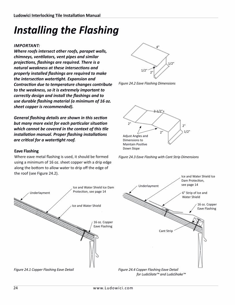
Eave FlashingWhere eave metal flashing is used, it should be formed using a minimum of 16 oz. sheet copper with a drip edge along the bottom to allow water to drip off the edge of the roof (see Figure 24.2).
Installing the Flashing
Figure 24.3 Eave Flashing with Cant Strip Dimensions
2"
1/2"
2"
2"
2-1/2"+
Adjust Angles and Dimensions to Maintain Positive Down Slope
IMPORTANT: Where roofs intersect other roofs, parapet walls, chimneys, ventilators, vent pipes and similar projections, flashings are required. There is a natural weakness at these intersections and properly installed flashings are required to make the intersection watertight. Expansion and Contraction due to temperature changes contribute to the weakness, so it is extremely important to correctly design and install the flashings and to use durable flashing material (a minimum of 16 oz. sheet copper is recommended).
General flashing details are shown in this section but many more exist for each particular situation which cannot be covered in the context of this tile installation manual. Proper flashing installations are critical for a watertight roof.
Underlayment
6" Strip of Ice and Water Shield
16 oz. Copper Eave Flashing
Cant Strip
Figure 24.4 Copper Flashing Eave Detail for LudoSlate™ and LudoShake™
Figure 24.1 Copper Flashing Eave Detail
Underlayment
Ice and Water Shield
16 oz. Copper Eave Flashing
Ice and Water Shield Ice Dam Protection, see page 14
Ice and Water Shield Ice Dam Protection, see page 14
Figure 24.2 Eave Flashing Dimensions
2"
4"
1/2"
1/2"

Ludowici Interlocking Tile Installation Manual
25www.Ludowic i .com
Rake Edge FlashingFor rake flashing, 16 oz. or heavier copper flashing should be installed to serve as a drip edge and as a finished edge.
The gable flashing is to be installed over the waterproof underlayment. For an open rake design the flashing must extend 5" onto the deck and 2" down over the fascia with a 1/2" hemmed edge (see Figure 25.1). For a Closed Rake design the flashing should extend 5" across the roof deck with V diverter and a hem at the edge. At the edge of the roof deck, the flashing is to extend up (perpendicular to the deck) 2" and back down at least 1-1/2" along the gable fascia board with a 1/2" crimp at the bottom edge to serve as a drip edge. The gable flashing pieces are to lap each other to form an overlap of at least 4". If using attached gable rake tile no flashing is required.
Figure 25.2 Closed Rake Flashing Dimensions
1/2"
1/2"
2-1/2"
3-1/2"
2-1/2"
3/8"3/8"
Figure 25.1 Open Rake Flashing Dimensions
2"
5-1/2"
1/2"
1/2"
Figure 25.6 Right Detached Rake Detail No Flashing Required
Right Detached Rake Tile
Adjust Flashing Size so the Top Edge is Even With the Highest Point of the Field Tile Off the Roof Deck
Figure 25.5 Closed Rake Detail
Figure 25.4 Open Rake Detail
16 oz. Copper Rake Flashing See 23.2
Wrap Underlayment 1" Over Fascia
For Left Rake Detail Trim Off Rain Channel for Flush Fit
Figure 25.3 Left Detached Rake Detail No Flashing Required *
End Band Tile
Left Detached Rake Tile
Wrap Underlayment 1" Over Fascia
End Band Tile
Wrap Underlayment 1" Over Fascia
Copper Cleats 24" O.C.
6" Strip of Ice and Water Shield
16 oz. Copper Rake Flashing See 23.1
Barge End Band Tile
Barge Full Field Tile
6" Strip of Ice and Water Shield
Tiles Overhang Fascia 1"
Ludowici Interlocking Tile Installation Manual
26 www.Ludowic i .com
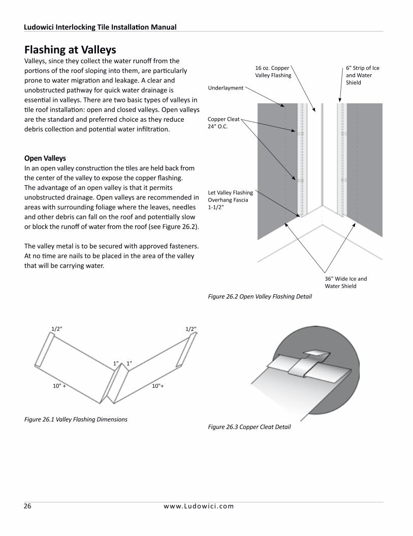
Figure 26.1 Valley Flashing Dimensions
1/2" 1/2"
10" + 10"+
1" 1"
Flashing at ValleysValleys, since they collect the water runoff from the portions of the roof sloping into them, are particularly prone to water migration and leakage. A clear and unobstructed pathway for quick water drainage is essential in valleys. There are two basic types of valleys in tile roof installation: open and closed valleys. Open valleys are the standard and preferred choice as they reduce debris collection and potential water infiltration.
Open ValleysIn an open valley construction the tiles are held back from the center of the valley to expose the copper flashing. The advantage of an open valley is that it permits unobstructed drainage. Open valleys are recommended in areas with surrounding foliage where the leaves, needles and other debris can fall on the roof and potentially slow or block the runoff of water from the roof (see Figure 26.2).
The valley metal is to be secured with approved fasteners. At no time are nails to be placed in the area of the valley that will be carrying water.
Figure 26.2 Open Valley Flashing Detail
Copper Cleat 24" O.C.
16 oz. Copper Valley Flashing
36" Wide Ice and Water Shield
6" Strip of Ice and Water Shield
Underlayment
Figure 26.3 Copper Cleat Detail
Let Valley Flashing Overhang Fascia 1-1/2"

Ludowici Interlocking Tile Installation Manual
27www.Ludowic i .com
Closed ValleysIn a closed valley, the tiles from the adjoining roof are mitered and abutted. Since water migrates through a closed valley onto the sheet copper flashing which carries the runoff, this type of construction is considered decorative.
NOTE: Underlayment for all valleys must be a full width sheet (36") of two layers of No. 43# coated base sheet or a layer of self-adhesive modified bitumen membrane. Each course from the adjoining fields must overlap the valley underlayment by at least 12".
Figure 27.1 Closed Valley Detail With Step Flashing
Valley Flashing Pieces Should Extend 11-1/2" from Valley Center Line
16 oz. Copper Valley Flashing Attached With Copper Cleats
36" Wide Ice and Water Shield
Figure 27.2 Closed Valley Flashing
Underlayment
Let Valley Flashing Overhang Fascia 1-1/2"
Center Rib Sized 1/4" Above Butt of Installed Tile
1/2" 1/2"
10" + 10" +
NOTE: Closed valleys should not be used where foliage debris can fall onto the roof, accumulate and cause water backup in the valley.
Closed valleys should not be used where the rafter length or pitch varies on adjacent roof planes. It is important that corresponding courses align coming into the valley.
Ludowici strongly discourages the use of closed valleys in areas with snow fall. Snow accumulation in a closed valley can cause ice dams, damaging the roof tile and creating potential leaks.
Ludowici Interlocking Tile Installation Manual
28 www.Ludowic i .com
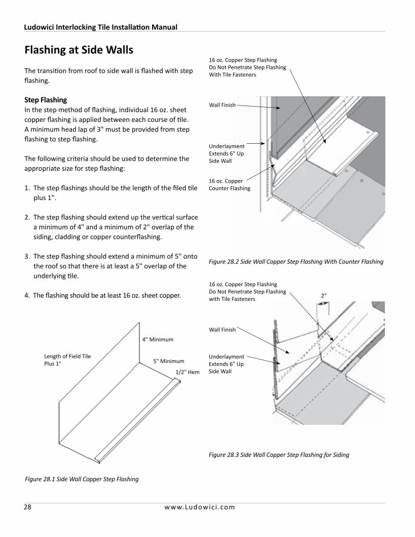
Flashing at Side Walls
The transition from roof to side wall is flashed with step flashing.
Step FlashingIn the step method of flashing, individual 16 oz. sheet copper flashing is applied between each course of tile. A minimum head lap of 3" must be provided from step flashing to step flashing.
The following criteria should be used to determine the appropriate size for step flashing:
1. The step flashings should be the length of the filed tile plus 1".
2. The step flashing should extend up the vertical surface a minimum of 4" and a minimum of 2" overlap of the siding, cladding or copper counterflashing.
3. The step flashing should extend a minimum of 5" onto the roof so that there is at least a 5" overlap of the underlying tile.
4. The flashing should be at least 16 oz. sheet copper.
Figure 28.1 Side Wall Copper Step Flashing
5" Minimum
4" Minimum
1/2" Hem
Length of Field Tile Plus 1"
Figure 28.2 Side Wall Copper Step Flashing With Counter Flashing
Underlayment Extends 6" Up Side Wall
16 oz. Copper Step FlashingDo Not Penetrate Step Flashing With Tile Fasteners
16 oz. Copper Counter Flashing
Wall Finish
Figure 28.3 Side Wall Copper Step Flashing for Siding
16 oz. Copper Step FlashingDo Not Penetrate Step Flashing with Tile Fasteners
Wall Finish
Underlayment Extends 6" Up Side Wall
2"
Ludowici Interlocking Tile Installation Manual
29www.Ludowic i .com
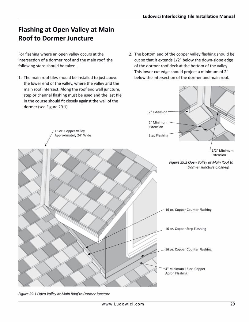
Flashing at Open Valley at Main Roof to Dormer Juncture
For flashing where an open valley occurs at the intersection of a dormer roof and the main roof, the following steps should be taken.
1. The main roof tiles should be installed to just above the lower end of the valley, where the valley and the main roof intersect. Along the roof and wall juncture, step or channel flashing must be used and the last tile in the course should fit closely against the wall of the dormer (see Figure 29.1).
2. The bottom end of the copper valley flashing should be cut so that it extends 1/2" below the down-slope edge of the dormer roof deck at the bottom of the valley. This lower cut edge should project a minimum of 2" below the intersection of the dormer and main roof.
16 oz. Copper Valley Approximately 24" Wide
16 oz. Copper Step Flashing
4" Minimum 16 oz. Copper Apron Flashing
16 oz. Copper Counter Flashing
Figure 29.1 Open Valley at Main Roof to Dormer Juncture
2" Extension
1/2" Minimum Extension
Step Flashing
2" Minimum Extension
Figure 29.2 Open Valley at Main Roof to Dormer Juncture Close-up
16 oz. Copper Counter Flashing
Ludowici Interlocking Tile Installation Manual
30 www.Ludowic i .com
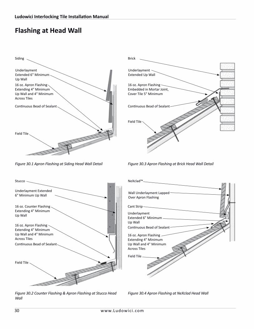
Flashing at Head Wall
Figure 30.1 Apron Flashing at Siding Head Wall Detail
Siding
16 oz. Apron Flashing Extending 4" Minimum Up Wall and 4" Minimum Across Tiles
Continuous Bead of Sealant
Field Tile
Underlayment Extended 6" MinimumUp Wall
Figure 30.2 Counter Flashing & Apron Flashing at Stucco Head Wall
Stucco
16 oz. Counter Flashing Extending 4" Minimum Up Wall
Continuous Bead of Sealant
Field Tile
16 oz. Apron Flashing Extending 4" Minimum Up Wall and 4" Minimum Across Tiles
Underlayment Extended 6" Minimum Up Wall
Figure 30.3 Apron Flashing at Brick Head Wall Detail
Brick
16 oz. Apron Flashing Embedded in Mortar Joint, Cover Tile 5" Minimum
Continuous Bead of Sealant
Field Tile
Underlayment Extended Up Wall
NeXclad™
16 oz. Apron Flashing Extending 4" Minimum Up Wall and 4" Minimum Across Tiles
Continuous Bead of Sealant
Field Tile
Wall Underlayment Lapped Over Apron Flashing
Figure 30.4 Apron Flashing at NeXclad Head Wall
Underlayment Extended 6" MinimumUp Wall
Cant Strip

Ludowici Interlocking Tile Installation Manual
31www.Ludowic i .com
Flashing at Chimney
Since the foundations of chimneys are usually structurally separate, the flashing around chimneys needs to be able to accommodate movement from differential settlement without compromising the watertightness of the roof. Regardless of the climate, install self-adhering Ice and Water Shield membrane around the base of the chimney before the underlayment is applied as a protection against ice dams. Four types of flashing are required to properly flash around chimneys.
1. Apron flashing at the down slope face over the installed tiles – 4" minimum exposed width, 6" up the face of the chimney and continuously counterflashed.
2. Step flashing along the sides of the chimney.
3. Cricket or backer flashing on the upslope side or back.
4. Continuous counterflashing embedded in masonry joints.
CounterflashingSheet copper counterflashing should be installed to overlap all vertical flashing flanges extended up the sides of chimneys. This is best accomplished by the mason during construction.
Figure 31.1 Chimney Flashing
16 oz. Copper Upslope Cricket Flashing
16 oz. Copper Counterflashing
16 oz. Copper Step Flashing at Each Course
6" Minimum
16 oz. Copper Apron Flashing 4" Minimum Up Chimney and 4" Minimum Across Tile
Ludowici Interlocking Tile Installation Manual
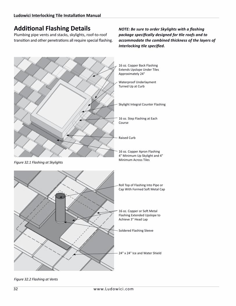
32 www.Ludowic i .com
Additional Flashing DetailsPlumbing pipe vents and stacks, skylights, roof-to-roof transition and other penetrations all require special flashing.
Figure 32.1 Flashing at Skylights
16 oz. Copper Back Flashing Extends Upslope Under Tiles Approximately 24"
Waterproof Underlayment Turned Up at Curb
Skylight Integral Counter Flashing
16 oz. Step Flashing at Each Course
Raised Curb
16 oz. Copper Apron Flashing 4" Minimum Up Skylight and 4" Minimum Across Tiles
NOTE: Be sure to order Skylights with a flashing package specifically designed for tile roofs and to accommodate the combined thickness of the layers of Interlocking tile specified.
Figure 32.2 Flashing at Vents
16 oz. Copper or Soft Metal Flashing Extended Upslope to Achieve 3" Head Lap
Roll Top of Flashing Into Pipe or Cap With Formed Soft Metal Cap
Soldered Flashing Sleeve
24" x 24" Ice and Water Shield

Ludowici Interlocking Tile Installation Manual
33www.Ludowic i .com
Figure 33.2 Flashing at Low Slope to High Slope TransitionFigure 33.1 Flashing at High Slope to Low Slope Transition
Field Tile
Cant Strip
16 oz. Copper Flashing 6" Minimum Upslope and 4" Minimum Downslope
Sealant
Underlayment
Field Tile
Cant Strip
16 oz. Copper Flashing 6" Minimum Upslope and 4" Minimum Downslope
Sealant
Underlayment
Under Eave
Extended 16 oz. Copper Drip Edge
16 oz. Copper Flashing4" Minimum Downslope
Sealant
Field Tile
Ice and Water Shield
16 oz. Copper Drip Edge
Under Eave
Figure 33.3 Built in Gutter Detail for Flat Interlocking Tile Figure 33.4 Built in Gutter Detail for French Interlocking Tile
Extended 16 oz. Copper Drip Edge
16 oz. Copper Flashing4" Minimum Downslope
Sealant
French Field Tile
Ice and Water Shield
Cant Strip
14"
Flashing at Pitch Change and Built In Gutter
Ludowici Interlocking Tile Installation Manual - Legacy Collection
34 www.Ludowic i .com
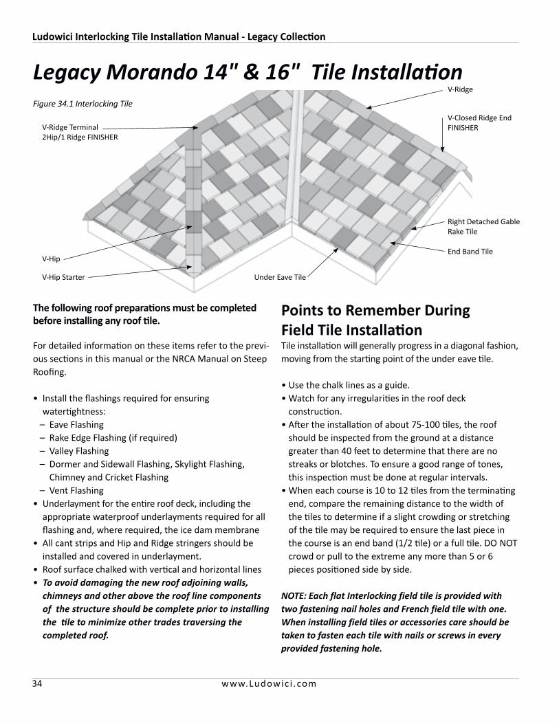
Legacy Morando 14" & 16" Tile Installation
NOTE: Each flat Interlocking field tile is provided with two fastening nail holes and French field tile with one. When installing field tiles or accessories care should be taken to fasten each tile with nails or screws in every provided fastening hole.
The following roof preparations must be completed before installing any roof tile.
For detailed information on these items refer to the previ-ous sections in this manual or the NRCA Manual on Steep Roofing.
• Install the flashings required for ensuring watertightness:
– Eave Flashing – Rake Edge Flashing (if required) – Valley Flashing – Dormer and Sidewall Flashing, Skylight Flashing,
Chimney and Cricket Flashing – Vent Flashing• Underlayment for the entire roof deck, including the
appropriate waterproof underlayments required for all flashing and, where required, the ice dam membrane
• All cant strips and Hip and Ridge stringers should be installed and covered in underlayment.
• Roof surface chalked with vertical and horizontal lines• To avoid damaging the new roof adjoining walls,
chimneys and other above the roof line components of the structure should be complete prior to installing the tile to minimize other trades traversing the completed roof.
Points to Remember During Field Tile InstallationTile installation will generally progress in a diagonal fashion, moving from the starting point of the under eave tile.
• Use the chalk lines as a guide.• Watch for any irregularities in the roof deck
construction.• After the installation of about 75-100 tiles, the roof
should be inspected from the ground at a distance greater than 40 feet to determine that there are no streaks or blotches. To ensure a good range of tones, this inspection must be done at regular intervals.
• When each course is 10 to 12 tiles from the terminating end, compare the remaining distance to the width of the tiles to determine if a slight crowding or stretching of the tile may be required to ensure the last piece in the course is an end band (1/2 tile) or a full tile. DO NOT crowd or pull to the extreme any more than 5 or 6 pieces positioned side by side.
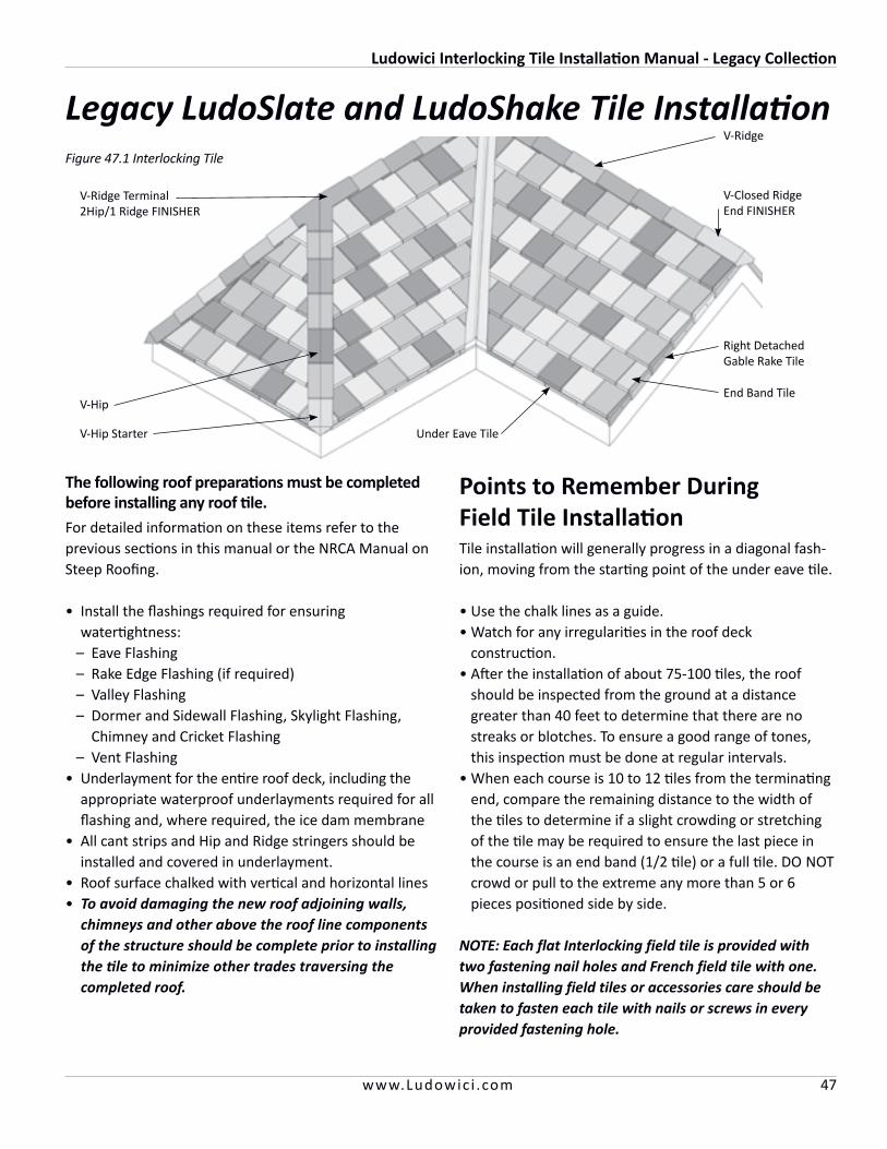
V-Ridge
V-Closed Ridge EndFINISHER
Under Eave Tile
Right Detached Gable Rake Tile
End Band Tile
V-Hip Starter
V-Hip
V-Ridge Terminal 2Hip/1 Ridge FINISHER
Figure 34.1 Interlocking Tile
Ludowici Interlocking Tile Installation Manual - Legacy Collection
35www.Ludowic i .com
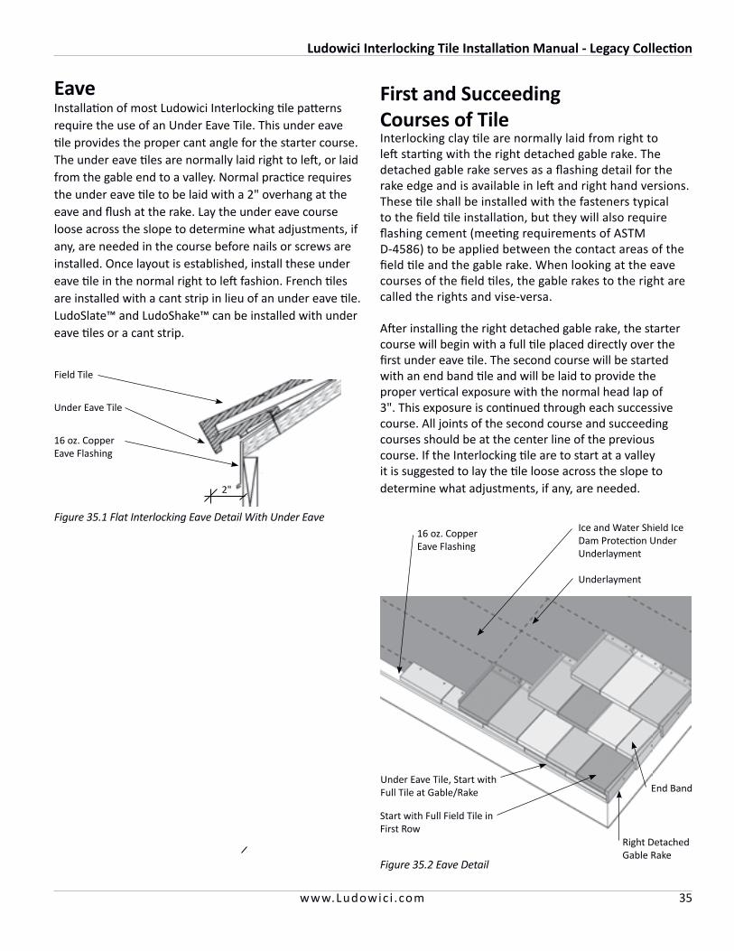
Eave Installation of most Ludowici Interlocking tile patterns require the use of an Under Eave Tile. This under eave tile provides the proper cant angle for the starter course. The under eave tiles are normally laid right to left, or laid from the gable end to a valley. Normal practice requires the under eave tile to be laid with a 2" overhang at the eave and flush at the rake. Lay the under eave course loose across the slope to determine what adjustments, if any, are needed in the course before nails or screws are installed. Once layout is established, install these under eave tile in the normal right to left fashion. French tiles are installed with a cant strip in lieu of an under eave tile. LudoSlate™ and LudoShake™ can be installed with under eave tiles or a cant strip.
Figure 35.2 Eave Detail
Under Eave Tile, Start with Full Tile at Gable/Rake
16 oz. Copper Eave Flashing
Ice and Water Shield Ice Dam Protection Under Underlayment
Start with Full Field Tile in First Row
Underlayment
End Band
Right Detached Gable Rake
First and Succeeding Courses of TileInterlocking clay tile are normally laid from right to left starting with the right detached gable rake. The detached gable rake serves as a flashing detail for the rake edge and is available in left and right hand versions. These tile shall be installed with the fasteners typical to the field tile installation, but they will also require flashing cement (meeting requirements of ASTM D-4586) to be applied between the contact areas of the field tile and the gable rake. When looking at the eave courses of the field tiles, the gable rakes to the right are called the rights and vise-versa.
After installing the right detached gable rake, the starter course will begin with a full tile placed directly over the first under eave tile. The second course will be started with an end band tile and will be laid to provide the proper vertical exposure with the normal head lap of 3". This exposure is continued through each successive course. All joints of the second course and succeeding courses should be at the center line of the previous course. If the Interlocking tile are to start at a valley it is suggested to lay the tile loose across the slope to determine what adjustments, if any, are needed.
Figure 35.1 Flat Interlocking Eave Detail With Under Eave
Field Tile
16 oz. Copper Eave Flashing
Under Eave Tile
2"
Ludowici Interlocking Tile Installation Manual - Legacy Collection
36 www.Ludowic i .com
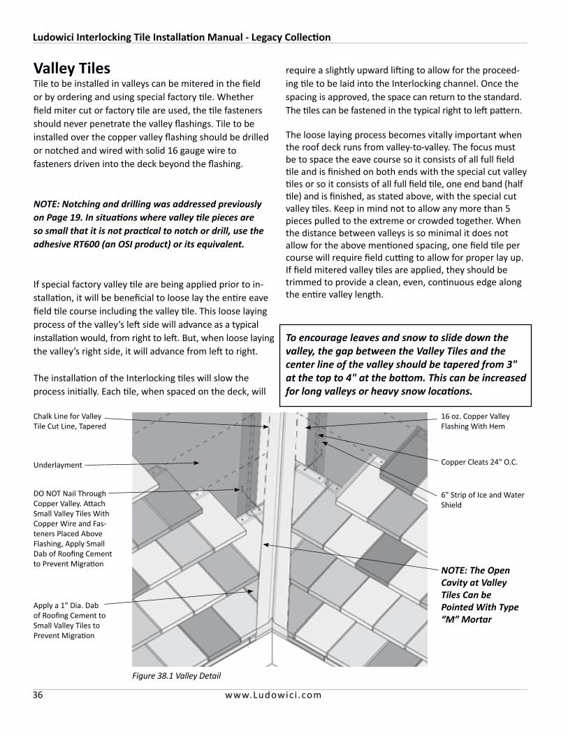
Valley TilesTile to be installed in valleys can be mitered in the field or by ordering and using special factory tile. Whether field miter cut or factory tile are used, the tile fasteners should never penetrate the valley flashings. Tile to be installed over the copper valley flashing should be drilled or notched and wired with solid 16 gauge wire to fasteners driven into the deck beyond the flashing.
NOTE: Notching and drilling was addressed previously on Page 19. In situations where valley tile pieces are so small that it is not practical to notch or drill, use the adhesive RT600 (an OSI product) or its equivalent.
If special factory valley tile are being applied prior to in-stallation, it will be beneficial to loose lay the entire eave field tile course including the valley tile. This loose laying process of the valley’s left side will advance as a typical installation would, from right to left. But, when loose laying the valley’s right side, it will advance from left to right.
The installation of the Interlocking tiles will slow the process initially. Each tile, when spaced on the deck, will
require a slightly upward lifting to allow for the proceed-ing tile to be laid into the Interlocking channel. Once the spacing is approved, the space can return to the standard. The tiles can be fastened in the typical right to left pattern.
The loose laying process becomes vitally important when the roof deck runs from valley-to-valley. The focus must be to space the eave course so it consists of all full field tile and is finished on both ends with the special cut valley tiles or so it consists of all full field tile, one end band (half tile) and is finished, as stated above, with the special cut valley tiles. Keep in mind not to allow any more than 5 pieces pulled to the extreme or crowded together. When the distance between valleys is so minimal it does not allow for the above mentioned spacing, one field tile per course will require field cutting to allow for proper lay up.If field mitered valley tiles are applied, they should be trimmed to provide a clean, even, continuous edge along the entire valley length.
Figure 38.1 Valley Detail
16 oz. Copper Valley Flashing With Hem
Copper Cleats 24" O.C.
6" Strip of Ice and Water Shield
Underlayment
DO NOT Nail Through Copper Valley. Attach Small Valley Tiles With Copper Wire and Fas-teners Placed Above Flashing, Apply Small Dab of Roofing Cement to Prevent Migration
Apply a 1" Dia. Dab of Roofing Cement to Small Valley Tiles to Prevent Migration
To encourage leaves and snow to slide down the valley, the gap between the Valley Tiles and the center line of the valley should be tapered from 3" at the top to 4" at the bottom. This can be increased for long valleys or heavy snow locations.
Chalk Line for Valley Tile Cut Line, Tapered
NOTE: The Open Cavity at Valley Tiles Can be Pointed With Type “M” Mortar

Ludowici Interlocking Tile Installation Manual - Legacy Collection
37www.Ludowic i .com
Hip TilesThere are a number of methods to finish the hips of Inter-locking tile roof depending on the design aestheticsdesired. These methods are flushed mitered, V-Hip tile or one of Ludowici’s other trim groups.
Tiles to be installed at hips are field mitered.
V-Hip and Other Cap Type Hip RollsHips are started with a special V-Hip Starter tile which should cover the field tile approximately 3" on both sides. The regular V-Hip tile is then installed by creating an ap-proximate 2" head lap on the V-Hip starter tile. This 2" head lap is continued up the hip and roofing cement is applied at each hip tile’s overlap. The last fastener on the upslope end of the hip is typically covered with a V-Hip and Ridge Terminal. Some roof termination may require a combination of typical flashing details or a special tile piece. Consult the local Ludowici sales representative for the project’s special roof requirements.
Figure 39.1 V-Hip Detail
Foundation Grade Hip Stringer Board, See Page 15 for Sizing Instructions
18" Strip of Ice and Water Shield
Hip Tiles Field Mitered Spaced 1/4" from Hip Stringer.
For Small Pieces Use Nail and Wire and Apply a 1" Dia. Dab of Roofing Cement to Small Pieces to Prevent Migration
Gap Between Hip Tile and Stringer Filled With Roofing Cement or Sealant Compatible with Ice and Water Shield
V-Hip Tile Laid With a 2" Lap
Bead of Sealant Between the Lap of V-Hip Tiles
V-Hip Starter
Roof PitchRise:Run
V-Hip 118 Hip 102 Hip CC Hip
4:12 2 1/4" 2 7/8" 4 3/4" 2 1/4"
5:12 2 1/4" 2 7/8" 4 5/8" 2 1/4"
6:12 2" 2 7/8" 4 5/8" 2"
7:12 2" 2 3/4" 4 1/2" 2"
8:12 1 3/4" 2 3/4" 4 1/2" 1 3/4"
9:12 1 3/4" 2 3/4" 4 3/8" 1 3/4"
10:12 1 1/2" 2 5/8" 4 3/8" 1 1/2"
11:12 1 1/2" 2 5/8" 4 1/4" 1 1/2"
12:12 1 1/4" 2 5/8" 4 1/4" 1 1/4"
13:12 1 1/4" 2 5/8" 4 1/8" 1 1/4"
14:12 1 1/4" 2 5/8" 4 1/8" 1 1/4"
Chart 39.1

Ludowici Interlocking Tile Installation Manual - Legacy Collection
38 www.Ludowic i .com
Mitered HipA flush mitered hip can be done by accurately miter-cutting the field tile and sealing the finished joint with an approved sealant, meeting the requirements of ASTM D-4586. Mitred hips require the use of copper step flashing on every course.
18" Strip of Ice and Water Shield
16 oz. Copper Step Flashing With 1/4" Lip at Each Course Set in a Thin Bed of Roofing Cement With 2 Copper Roofing Nails at Top
Field Cut Mitred Hip Tiles and Set in a Thin Bed of Roofing Cement
Apply a Bead of Sealant to Hip Joint Between Tiles
Figure 38.1 Mitred Hip Detail
V-Ridge
RidgeFigure 38.2 V-Ridge Detail
V-Ridge Laid With a Minimum 2" Lap
Roofing Cement
Foundation Grade Wood Stringer, 1-1/2" Wide by Proper Height. See Page 15 for Sizing Instruction
18" Wide Strip of Ice and Water Shield
Interlocking Filed Tile
Ludowici Interlocking Tile Installation Manual - Legacy Collection
39www.Ludowic i .com
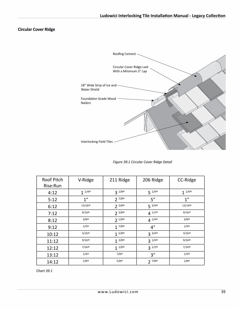
Roof PitchRise:Run
V-Ridge 211 Ridge 206 Ridge CC-Ridge
4:12 1 1/4" 3 1/8" 5 1/4" 1 1/4"5:12 1" 2 7/8" 5" 1"6:12 13/16" 2 5/8" 5 3/4" 13/16"7:12 9/16" 2 3/8" 4 1/2" 9/16"8:12 3/8" 2 1/8" 4 1/4" 3/8"9:12 1/4" 1 7/8" 4" 1/4"
10:12 3/16" 1 5/8" 3 3/4" 3/16"11:12 9/16" 1 3/8" 3 1/4" 9/16"12:12 7/16" 1 1/8" 3 1/2" 7/16"13:12 1/4" 7/8" 3" 1/4"14:12 1/8" 5/8" 2 7/8" 1/8"
Chart 39.1
Circular Cover Ridge
Figure 39.1 Circular Cover Ridge Detail
18" Wide Strip of Ice and Water Shield
Foundation Grade Wood Nailers
Interlocking Field Tiles
Circular Cover Ridge Laid With a Minimum 3" Lap
Roofing Cement
Ludowici Interlocking Tile Installation Manual - Legacy Collection
40 www.Ludowic i .com
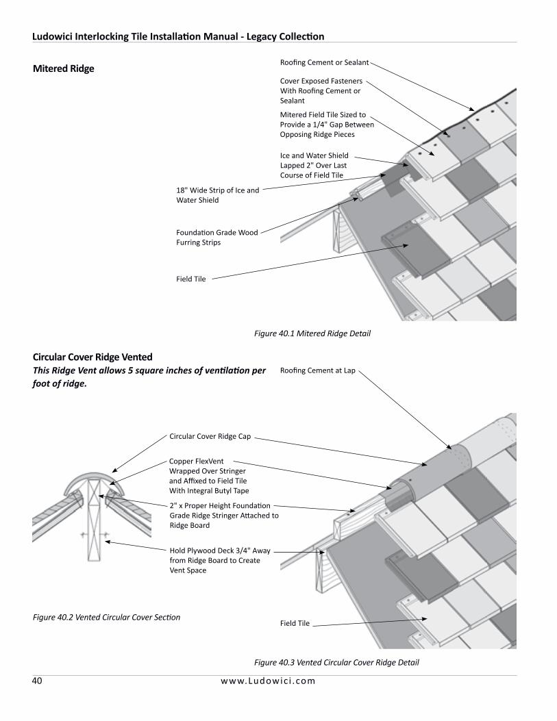
Mitered Ridge
Circular Cover Ridge VentedThis Ridge Vent allows 5 square inches of ventilation per foot of ridge.
Figure 40.3 Vented Circular Cover Ridge Detail
Figure 40.1 Mitered Ridge Detail
18" Wide Strip of Ice and Water Shield
Ice and Water Shield Lapped 2" Over Last Course of Field Tile
Foundation Grade Wood Furring Strips
Field Tile
Cover Exposed Fasteners With Roofing Cement or Sealant
Mitered Field Tile Sized to Provide a 1/4" Gap Between Opposing Ridge Pieces
Circular Cover Ridge Cap
Roofing Cement at Lap
Copper FlexVent Wrapped Over Stringer and Affixed to Field Tile With Integral Butyl Tape
2" x Proper Height Foundation Grade Ridge Stringer Attached to Ridge Board
Field TileFigure 40.2 Vented Circular Cover Section
Roofing Cement or Sealant
Hold Plywood Deck 3/4" Away from Ridge Board to Create Vent Space
Ludowici Interlocking Tile Installation Manual - Legacy Collection
41www.Ludowic i .com
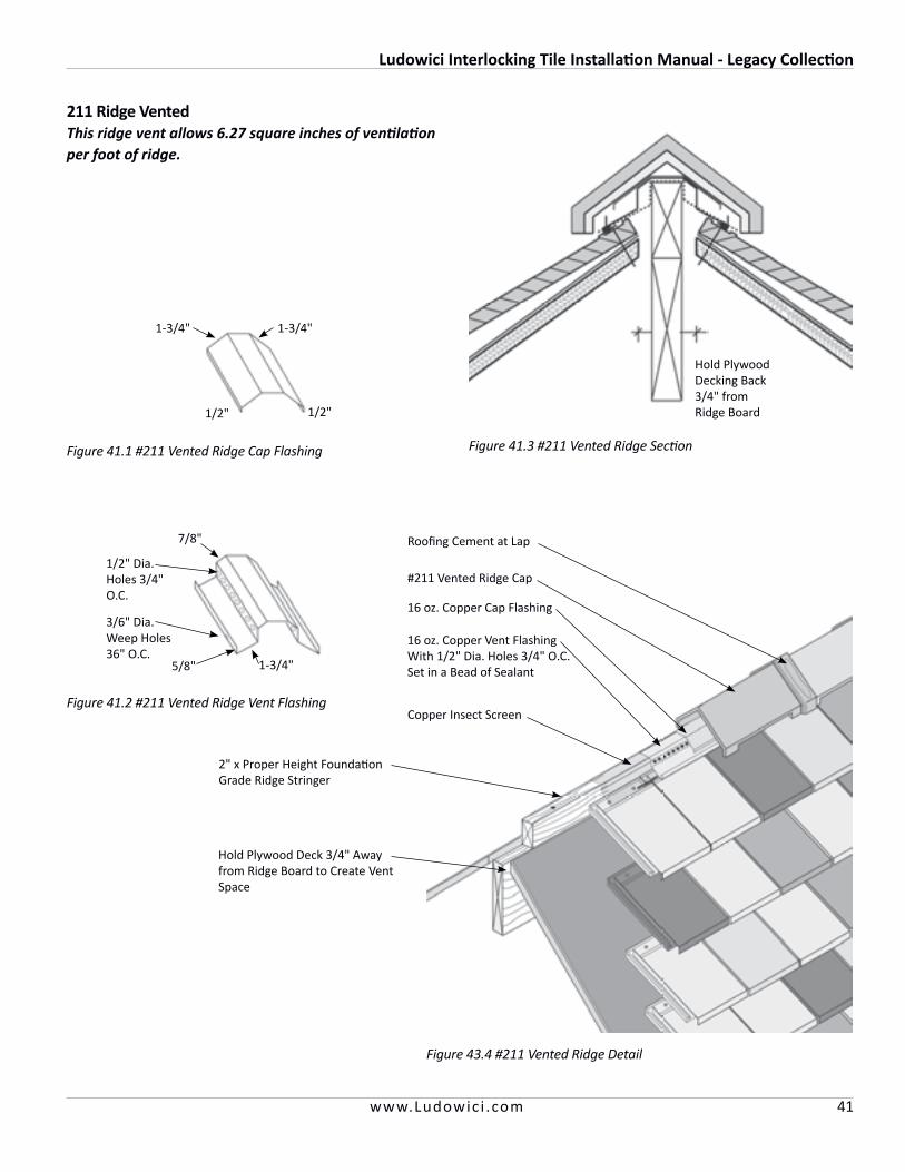
211 Ridge VentedThis ridge vent allows 6.27 square inches of ventilation per foot of ridge.
Figure 43.4 #211 Vented Ridge Detail
#211 Vented Ridge Cap
Roofing Cement at Lap
16 oz. Copper Vent Flashing With 1/2" Dia. Holes 3/4" O.C. Set in a Bead of Sealant
2" x Proper Height Foundation Grade Ridge Stringer
Hold Plywood Deck 3/4" Away from Ridge Board to Create Vent Space
16 oz. Copper Cap Flashing
Copper Insect Screen
Figure 41.1 #211 Vented Ridge Cap Flashing
Figure 41.2 #211 Vented Ridge Vent Flashing
1/2"
1-3/4"1-3/4"
1/2"
5/8" 1-3/4"
7/8"
1/2" Dia. Holes 3/4" O.C.
3/6" Dia. Weep Holes36" O.C.
Figure 41.3 #211 Vented Ridge Section
Hold Plywood Decking Back 3/4" from Ridge Board
Ludowici Interlocking Tile Installation Manual - Legacy Collection
42 www.Ludowic i .com
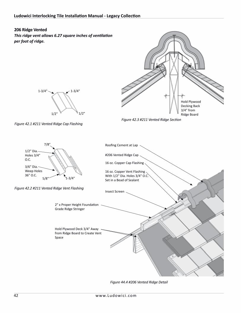
206 Ridge VentedThis ridge vent allows 6.27 square inches of ventilation per foot of ridge.
Figure 44.4 #206 Vented Ridge Detail
#206 Vented Ridge Cap
Roofing Cement at Lap
16 oz. Copper Vent Flashing With 1/2" Dia. Holes 3/4" O.C. Set in a Bead of Sealant
2" x Proper Height Foundation Grade Ridge Stringer
Hold Plywood Deck 3/4" Away from Ridge Board to Create Vent Space
16 oz. Copper Cap Flashing
Insect Screen
Figure 42.1 #211 Vented Ridge Cap Flashing
Figure 42.2 #211 Vented Ridge Vent Flashing
1/2"
1-3/4"1-3/4"
1/2"
5/8" 1-3/4"
7/8"
1/2" Dia. Holes 3/4" O.C.
3/6" Dia. Weep Holes36" O.C.
Figure 42.3 #211 Vented Ridge Section
Hold Plywood Decking Back 3/4" from Ridge Board

Ludowici Interlocking Tile Installation Manual - Legacy Collection
43www.Ludowic i .com
Figure 43.2 Left Rake Step FlashingFigure 43.1 Left Rake Step Flashing for Field Cut Field Tiles
Figure 43.5 Deck Section with #211 Ridge
Figure 43.3 Deck Section with #211 Deck Mold Raised Flange Figure 43.4 Deck Section with #206 Deck Mold Raised Flange
Figure 43.6 Deck Section with #211 Cut-Off Ridge
Underlayment, Wrap 1" Over Fascia
16 oz. Copper Step Flashing at Each Course
Field Tile Field Cut
Left Detached Gable Rake
16 oz. Copper Cap Flashing
Apply Sealant or Roofing Cement to Prevent Small Tiles from Migrating
Figure 45.1 For conditions where inadequate spacing
doesn’t allow for the use of full field tiles and end bands.
Width=3/4 the Width of Field Tile
Length=Field Tile less 1/2"
1/2" Hem
Sealant
#211 Deck Mold Raised Flange
Sealant
Underlayment
16 oz. Copper Cap Flashing
Sealant
#206 Deck Mold Raised Flange
Sealant
Underlayment
16 oz. Copper Cap Flashing
#211 Ridge
Sealant
Underlayment
Flat Roof Material
16 oz. Copper Cap Flashing
#211 Cut-Off Ridge
Sealant
Underlayment

Ludowici Interlocking Tile Installation Manual - Legacy Collection
44 www.Ludowic i .com
TerminalsLudowici makes ridge end caps for all trim groups. Ridge end caps come as a starter or finisher, (a male/female lap). Care should be taken to determine correct orientation of the parts ordered and the proper installation sequence to accommodate the installation with minimal cutting.
Ludowici manufactures Terminals to accommodate Ridge and Hip transitions. These are the most effective way to waterproof the transition and finish it in an aesthetically pleasing manor. Terminals are also made with a starter and finisher.
Figure 44.1 Vertical Wall Corner
Vertical Wall ApplicationFlat Shingle or Interlocking tile can be used on a vertical surface. For Shingle tile, short tops and long tops and under eave cant strips are used. For Interlocking tile, use cant strips where needed.
Special Order Siding Corner
Can Also be Field Mitered
Figure 44.4 Vertical Wall Section
Fascia
Short Top Tile
Roofing Cement
Long Top Tile
Roofing Cement
Roofing Cement
16 oz. Copper Step Flashing See Figure 26.1
Foundation Grade Wood Nailers
Underlayment
Under Eave Tile
Foundation Grade Wood Cant Strip
Roof Deck
Figure 44.2 Ridge Starter Finisher Diagram
Figure 44.3 Typical 2 Hip/1 Ridge V-Terminal
Starter End Finisher EndStarter End Finisher End
#211 Ridge #206 Ridge

Ludowici Interlocking Tile Installation Manual - Legacy Collection
45www.Ludowic i .com
Figure 44.4 Vertical Wall Section
Staggered ApplicationLudoSlate™ and LudoShake™ can be laid with staggered butts to achieve a more rustic appearance.
The roofer will need to snap off the waterlock knockouts on both the lower left corner and the upper right corner to allow the tiles to be laid staggered.
Strike the chalk lines in the same method as a standard installation. Lay the first course in a straight line. On the second and above courses lay the tiles on the chalk line and randomly drop some up to 3/4" below the chalk line to achieve the random staggered look.
Figure 45.3 Staggered Layout
Nip Off the Waterlock Knock Out to Allow Staggered Lay Up
Nip Off the Waterlock Knock Out to Allow Staggered Lay Up
Figure 47.2 Staggered Tile Prep
First Row of Tiles Installed With No Stagger
Snow GuardsSnow guards are generally required in areas where snow and ice may accumulate on the roof. Snow guards are sometimes used on sloped roofs to prevent a mass of snow or ice from sliding off the roofs and injuring persons, damaging gutters or plants and blocking walks and driveways. Snow guards hold the snow in place above the eaves until it can melt and the water runs off.
It is recommended that snow guards should be installed on at least 3 or 4 courses, offset from course to course, spaced in staggered interval rows. Begin with the third or fourth row. However, spacing and quantity of snow guards is a matter of judgement based on local weather conditions (see Figure 47.1).
Alpine conditions will require a professional engineer to design the required snow retainage system. Tile should not be exposed to ice and snow loads exceeding 100 pounds per square foot.
A snow guard must be made of nonferrous material to prevent possible rust stains.
Figure 45.1 Snow Guard Spacing
Ludowici Interlocking Tile Installation Manual - Legacy Collection
46 www.Ludowic i .com
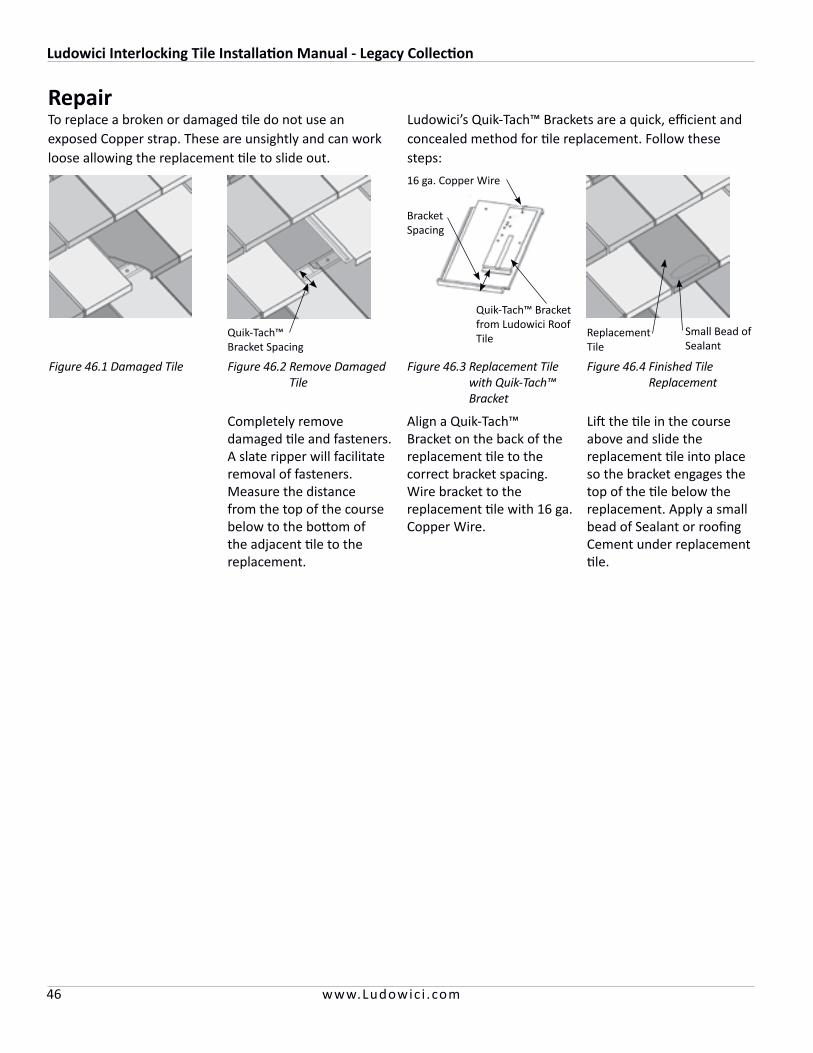
RepairTo replace a broken or damaged tile do not use an exposed Copper strap. These are unsightly and can work loose allowing the replacement tile to slide out.
Completely remove damaged tile and fasteners. A slate ripper will facilitate removal of fasteners. Measure the distance from the top of the course below to the bottom of the adjacent tile to the replacement.
Align a Quik-Tach™ Bracket on the back of the replacement tile to the correct bracket spacing. Wire bracket to the replacement tile with 16 ga. Copper Wire.
Lift the tile in the course above and slide the replacement tile into place so the bracket engages the top of the tile below the replacement. Apply a small bead of Sealant or roofing Cement under replacement tile.
Quik-Tach™ Bracket Spacing
Replacement Tile
Small Bead of Sealant
Figure 46.3 Replacement Tile with Quik-Tach™ Bracket
Figure 46.2 Remove Damaged Tile
Figure 46.1 Damaged Tile
Ludowici’s Quik-Tach™ Brackets are a quick, efficient and concealed method for tile replacement. Follow these steps:
Figure 46.4 Finished Tile Replacement
Quik-Tach™ Bracket from Ludowici Roof Tile
16 ga. Copper Wire
Bracket Spacing
Ludowici Interlocking Tile Installation Manual - Legacy Collection
47www.Ludowic i .com
Legacy LudoSlate and LudoShake Tile Installation
NOTE: Each flat Interlocking field tile is provided with two fastening nail holes and French field tile with one. When installing field tiles or accessories care should be taken to fasten each tile with nails or screws in every provided fastening hole.
The following roof preparations must be completed before installing any roof tile. For detailed information on these items refer to the previous sections in this manual or the NRCA Manual on Steep Roofing.
• Install the flashings required for ensuring watertightness:
– Eave Flashing – Rake Edge Flashing (if required) – Valley Flashing – Dormer and Sidewall Flashing, Skylight Flashing,
Chimney and Cricket Flashing – Vent Flashing• Underlayment for the entire roof deck, including the
appropriate waterproof underlayments required for all flashing and, where required, the ice dam membrane
• All cant strips and Hip and Ridge stringers should be installed and covered in underlayment.
• Roof surface chalked with vertical and horizontal lines• To avoid damaging the new roof adjoining walls,
chimneys and other above the roof line components of the structure should be complete prior to installing the tile to minimize other trades traversing the completed roof.
Points to Remember During Field Tile InstallationTile installation will generally progress in a diagonal fash-ion, moving from the starting point of the under eave tile.
• Use the chalk lines as a guide.• Watch for any irregularities in the roof deck
construction.• After the installation of about 75-100 tiles, the roof
should be inspected from the ground at a distance greater than 40 feet to determine that there are no streaks or blotches. To ensure a good range of tones, this inspection must be done at regular intervals.
• When each course is 10 to 12 tiles from the terminating end, compare the remaining distance to the width of the tiles to determine if a slight crowding or stretching of the tile may be required to ensure the last piece in the course is an end band (1/2 tile) or a full tile. DO NOT crowd or pull to the extreme any more than 5 or 6 pieces positioned side by side.
V-Ridge
V-Closed Ridge End FINISHER
Under Eave Tile
Right Detached Gable Rake Tile
End Band Tile
V-Hip Starter
V-Hip
V-Ridge Terminal 2Hip/1 Ridge FINISHER
Figure 47.1 Interlocking Tile

Ludowici Interlocking Tile Installation Manual - Legacy Collection
48 www.Ludowic i .com
Eave Installation of most Ludowici Interlocking tile patterns require the use of an Under Eave Tile. This under eave tile provides the proper cant angle for the starter course. The under eave tiles are normally laid right to left, or laid from the gable end to a valley. Normal practice requires the under eave tile to be laid with a 2" overhang at the eave and flush at the rake. Lay the under eave course loose across the slope to determine what adjustments, if any, are needed in the course before nails or screws are installed. Once layout is established, install these under eave tile in the normal right to left fashion. French tiles are installed with a cant strip in lieu of an under eave tile. LudoSlate™ and LudoShake™ can be installed with under eave tiles or a cant strip.
Figure 48.2 Eave Detail
Under Eave Tile, Start with Full Tile at Gable/Rake
16 oz. Copper Eave Flashing
Ice and Water Shield Ice Dam Protection Under Underlayment
Start with Full Field Tile in First Row
Underlayment
End Band
Right Detached Gable Rake
First and Succeeding Courses of TileInterlocking clay tile are normally laid from right to left starting with the right detached gable rake. The detached gable rake serves as a flashing detail for the rake edge and is available in left and right hand versions.These tile shall be installed with the fasteners typical to the field tile installation, but they will also require flashing cement (meeting requirements of ASTM D-4586) to be applied between the contact areas of the field tile and the gable rake. When looking at the eave courses of the field tiles, the gable rakes to the right are called the rights and vise-versa.
After installing the right detached gable rake, the starter course will begin with a full tile placed directly over the first under eave tile. The second course will be started with an end band tile and will be laid to provide the proper vertical exposure with the normal head lap of 3". This exposure is continued through each successive course. All joints of the second course and succeeding courses should be at the center line of the previous course. If the Interlocking tile are to start at a valley it is suggested to lay the tile loose across the slope to determine what adjustments, if any, are needed.
Figure 48.1 LudoSlate™ and LudoShake™ Eave Detail with Cant Strip
Field Tile
16 oz. Copper Eave Flashing
Cant Strip
2"
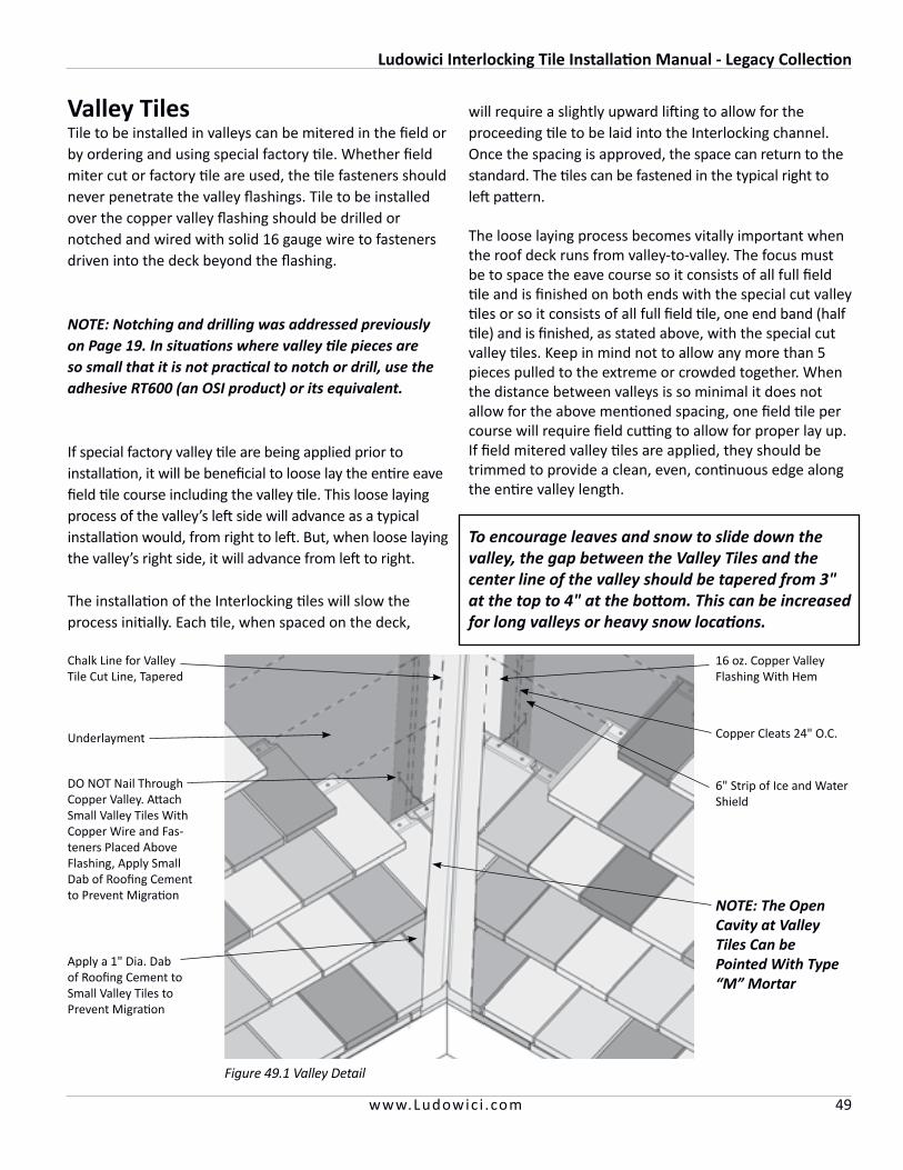
Ludowici Interlocking Tile Installation Manual - Legacy Collection
49www.Ludowic i .com
End Band
Valley TilesTile to be installed in valleys can be mitered in the field or by ordering and using special factory tile. Whether field miter cut or factory tile are used, the tile fasteners should never penetrate the valley flashings. Tile to be installed over the copper valley flashing should be drilled or notched and wired with solid 16 gauge wire to fasteners driven into the deck beyond the flashing.
NOTE: Notching and drilling was addressed previously on Page 19. In situations where valley tile pieces are so small that it is not practical to notch or drill, use the adhesive RT600 (an OSI product) or its equivalent.
If special factory valley tile are being applied prior to installation, it will be beneficial to loose lay the entire eave field tile course including the valley tile. This loose laying process of the valley’s left side will advance as a typical installation would, from right to left. But, when loose laying the valley’s right side, it will advance from left to right.
The installation of the Interlocking tiles will slow the process initially. Each tile, when spaced on the deck,
will require a slightly upward lifting to allow for the proceeding tile to be laid into the Interlocking channel. Once the spacing is approved, the space can return to the standard. The tiles can be fastened in the typical right to left pattern.
The loose laying process becomes vitally important when the roof deck runs from valley-to-valley. The focus must be to space the eave course so it consists of all full field tile and is finished on both ends with the special cut valley tiles or so it consists of all full field tile, one end band (half tile) and is finished, as stated above, with the special cut valley tiles. Keep in mind not to allow any more than 5 pieces pulled to the extreme or crowded together. When the distance between valleys is so minimal it does not allow for the above mentioned spacing, one field tile per course will require field cutting to allow for proper lay up.If field mitered valley tiles are applied, they should be trimmed to provide a clean, even, continuous edge along the entire valley length.
Figure 49.1 Valley Detail
16 oz. Copper Valley Flashing With Hem
Copper Cleats 24" O.C.
6" Strip of Ice and Water Shield
Underlayment
DO NOT Nail Through Copper Valley. Attach Small Valley Tiles With Copper Wire and Fas-teners Placed Above Flashing, Apply Small Dab of Roofing Cement to Prevent Migration
Apply a 1" Dia. Dab of Roofing Cement to Small Valley Tiles to Prevent Migration
To encourage leaves and snow to slide down the valley, the gap between the Valley Tiles and the center line of the valley should be tapered from 3" at the top to 4" at the bottom. This can be increased for long valleys or heavy snow locations.
Chalk Line for Valley Tile Cut Line, Tapered
NOTE: The Open Cavity at Valley Tiles Can be Pointed With Type “M” Mortar
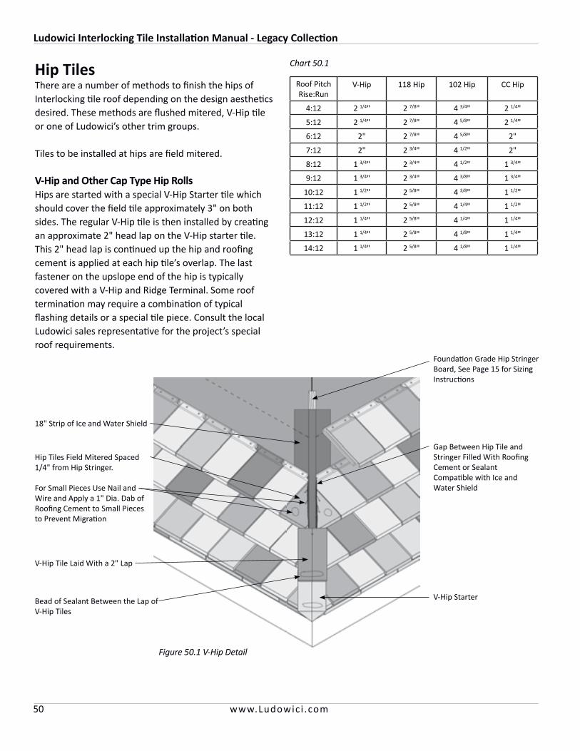
Ludowici Interlocking Tile Installation Manual - Legacy Collection
50 www.Ludowic i .com
Hip TilesThere are a number of methods to finish the hips of Interlocking tile roof depending on the design aestheticsdesired. These methods are flushed mitered, V-Hip tile or one of Ludowici’s other trim groups.
Tiles to be installed at hips are field mitered.
V-Hip and Other Cap Type Hip RollsHips are started with a special V-Hip Starter tile which should cover the field tile approximately 3" on both sides. The regular V-Hip tile is then installed by creating an approximate 2" head lap on the V-Hip starter tile. This 2" head lap is continued up the hip and roofing cement is applied at each hip tile’s overlap. The last fastener on the upslope end of the hip is typically covered with a V-Hip and Ridge Terminal. Some roof termination may require a combination of typical flashing details or a special tile piece. Consult the local Ludowici sales representative for the project’s special roof requirements.
Figure 50.1 V-Hip Detail
Foundation Grade Hip Stringer Board, See Page 15 for Sizing Instructions
18" Strip of Ice and Water Shield
Hip Tiles Field Mitered Spaced 1/4" from Hip Stringer.
For Small Pieces Use Nail and Wire and Apply a 1" Dia. Dab of Roofing Cement to Small Pieces to Prevent Migration
Gap Between Hip Tile and Stringer Filled With Roofing Cement or Sealant Compatible with Ice and Water Shield
V-Hip Tile Laid With a 2" Lap
Bead of Sealant Between the Lap of V-Hip Tiles
V-Hip Starter
Roof PitchRise:Run
V-Hip 118 Hip 102 Hip CC Hip
4:12 2 1/4" 2 7/8" 4 3/4" 2 1/4"
5:12 2 1/4" 2 7/8" 4 5/8" 2 1/4"
6:12 2" 2 7/8" 4 5/8" 2"
7:12 2" 2 3/4" 4 1/2" 2"
8:12 1 3/4" 2 3/4" 4 1/2" 1 3/4"
9:12 1 3/4" 2 3/4" 4 3/8" 1 3/4"
10:12 1 1/2" 2 5/8" 4 3/8" 1 1/2"
11:12 1 1/2" 2 5/8" 4 1/4" 1 1/2"
12:12 1 1/4" 2 5/8" 4 1/4" 1 1/4"
13:12 1 1/4" 2 5/8" 4 1/8" 1 1/4"
14:12 1 1/4" 2 5/8" 4 1/8" 1 1/4"
Chart 50.1
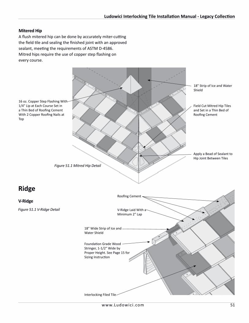
Ludowici Interlocking Tile Installation Manual - Legacy Collection
51www.Ludowic i .com
Mitered HipA flush mitered hip can be done by accurately miter-cutting the field tile and sealing the finished joint with an approved sealant, meeting the requirements of ASTM D-4586. Mitred hips require the use of copper step flashing on every course.
18" Strip of Ice and Water Shield
16 oz. Copper Step Flashing With 1/4" Lip at Each Course Set in a Thin Bed of Roofing Cement With 2 Copper Roofing Nails at Top
Field Cut Mitred Hip Tiles and Set in a Thin Bed of Roofing Cement
Apply a Bead of Sealant to Hip Joint Between Tiles
Figure 51.1 Mitred Hip Detail
V-Ridge
Ridge
V-Ridge Laid With a Minimum 2" Lap
Roofing Cement
Foundation Grade Wood Stringer, 1-1/2" Wide by Proper Height. See Page 15 for Sizing Instruction
18" Wide Strip of Ice and Water Shield
Interlocking Filed Tile
Figure 51.1 V-Ridge Detail
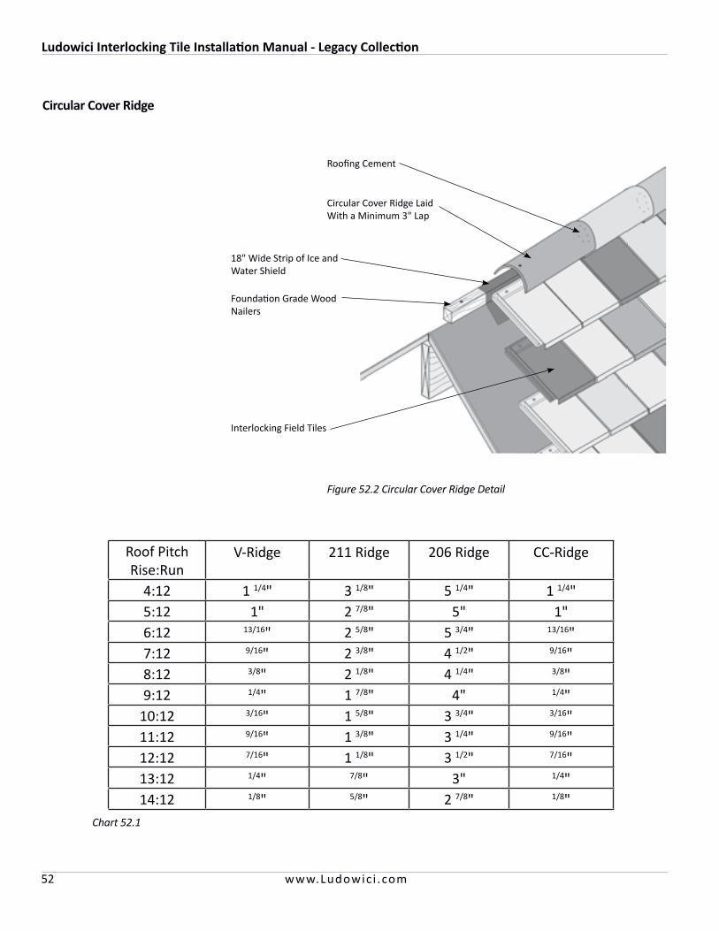
Ludowici Interlocking Tile Installation Manual - Legacy Collection
52 www.Ludowic i .com
Circular Cover Ridge
Figure 52.2 Circular Cover Ridge Detail
18" Wide Strip of Ice and Water Shield
Foundation Grade Wood Nailers
Interlocking Field Tiles
Circular Cover Ridge Laid With a Minimum 3" Lap
Roofing Cement
Roof PitchRise:Run
V-Ridge 211 Ridge 206 Ridge CC-Ridge
4:12 1 1/4" 3 1/8" 5 1/4" 1 1/4"5:12 1" 2 7/8" 5" 1"6:12 13/16" 2 5/8" 5 3/4" 13/16"7:12 9/16" 2 3/8" 4 1/2" 9/16"8:12 3/8" 2 1/8" 4 1/4" 3/8"9:12 1/4" 1 7/8" 4" 1/4"
10:12 3/16" 1 5/8" 3 3/4" 3/16"11:12 9/16" 1 3/8" 3 1/4" 9/16"12:12 7/16" 1 1/8" 3 1/2" 7/16"13:12 1/4" 7/8" 3" 1/4"14:12 1/8" 5/8" 2 7/8" 1/8"
Chart 52.1

Ludowici Interlocking Tile Installation Manual - Legacy Collection
53www.Ludowic i .com
Mitered Ridge
Circular Cover Ridge VentedThis Ridge Vent allows 5 square inches of ventilation per foot of ridge.
Figure 53.3 Vented Circular Cover Ridge Detail
Figure 53.2 Mitered Ridge Detail
18" Wide Strip of Ice and Water Shield
Ice and Water Shield Lapped 2" Over Last Course of Field Tile
Foundation Grade Wood Furring Strips
Field Tile
Cover Exposed Fasteners With Roofing Cement or Sealant
Mitered Field Tile Sized to Provide a 1/4" Gap Between Opposing Ridge Pieces
Circular Cover Ridge Cap
Roofing Cement at Lap
Copper FlexVent Wrapped Over Stringer and Affixed to Field Tile With Integral Butyl Tape
2" x Proper Height Foundation Grade Ridge Stringer Attached to Ridge Board
Field TileFigure 55.1 Vented Circular Cover Section
Roofing Cement or Sealant
Hold Plywood Deck 3/4" Away from Ridge Board to Create Vent Space
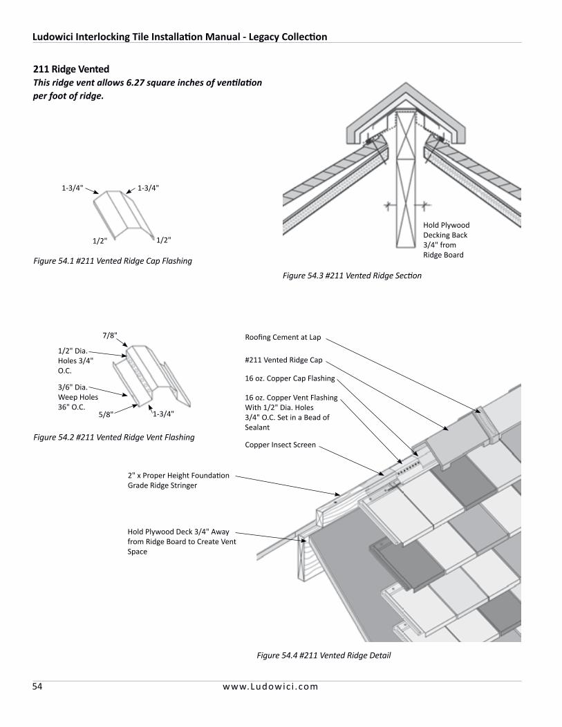
Ludowici Interlocking Tile Installation Manual - Legacy Collection
54 www.Ludowic i .com
211 Ridge VentedThis ridge vent allows 6.27 square inches of ventilation per foot of ridge.
Figure 54.4 #211 Vented Ridge Detail
#211 Vented Ridge Cap
Roofing Cement at Lap
16 oz. Copper Vent Flashing With 1/2" Dia. Holes 3/4" O.C. Set in a Bead of Sealant
2" x Proper Height Foundation Grade Ridge Stringer
Hold Plywood Deck 3/4" Away from Ridge Board to Create Vent Space
16 oz. Copper Cap Flashing
Copper Insect Screen
Figure 54.1 #211 Vented Ridge Cap Flashing
Figure 54.2 #211 Vented Ridge Vent Flashing
1/2"
1-3/4"1-3/4"
1/2"
5/8" 1-3/4"
7/8"
1/2" Dia. Holes 3/4" O.C.
3/6" Dia. Weep Holes36" O.C.
Figure 54.3 #211 Vented Ridge Section
Hold Plywood Decking Back 3/4" from Ridge Board
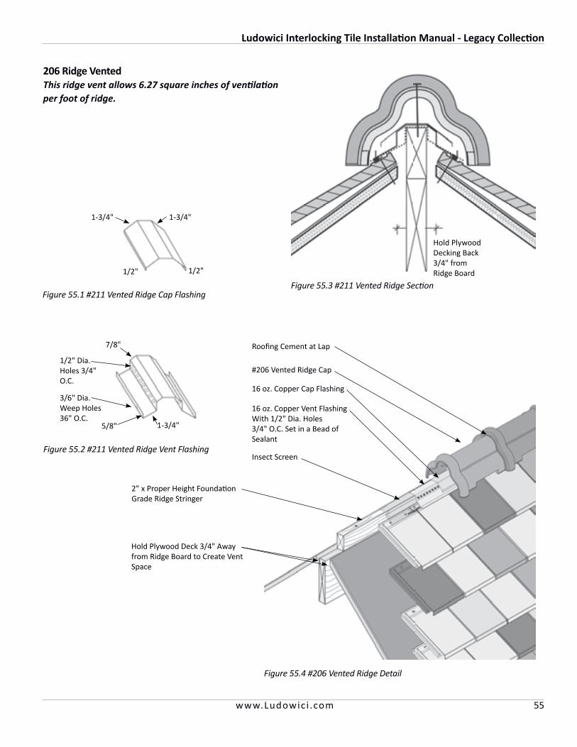
Ludowici Interlocking Tile Installation Manual - Legacy Collection
55www.Ludowic i .com
206 Ridge VentedThis ridge vent allows 6.27 square inches of ventilation per foot of ridge.
Figure 55.4 #206 Vented Ridge Detail
#206 Vented Ridge Cap
Roofing Cement at Lap
16 oz. Copper Vent Flashing With 1/2" Dia. Holes 3/4" O.C. Set in a Bead of Sealant
2" x Proper Height Foundation Grade Ridge Stringer
Hold Plywood Deck 3/4" Away from Ridge Board to Create Vent Space
16 oz. Copper Cap Flashing
Insect Screen
Figure 55.1 #211 Vented Ridge Cap Flashing
Figure 55.2 #211 Vented Ridge Vent Flashing
1/2"
1-3/4"1-3/4"
1/2"
5/8" 1-3/4"
7/8"
1/2" Dia. Holes 3/4" O.C.
3/6" Dia. Weep Holes36" O.C.
Figure 55.3 #211 Vented Ridge Section
Hold Plywood Decking Back 3/4" from Ridge Board
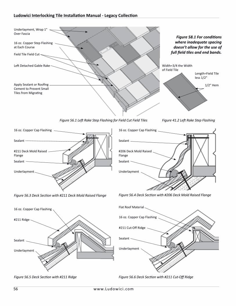
Ludowici Interlocking Tile Installation Manual - Legacy Collection
56 www.Ludowic i .com
Figure 41.2 Left Rake Step FlashingFigure 56.1 Left Rake Step Flashing for Field Cut Field Tiles
Figure 56.5 Deck Section with #211 Ridge
Figure 56.3 Deck Section with #211 Deck Mold Raised Flange Figure 56.4 Deck Section with #206 Deck Mold Raised Flange
Figure 56.6 Deck Section with #211 Cut-Off Ridge
Underlayment, Wrap 1" Over Fascia
16 oz. Copper Step Flashing at Each Course
Field Tile Field Cut
Left Detached Gable Rake
16 oz. Copper Cap Flashing
Apply Sealant or Roofing Cement to Prevent Small Tiles from Migrating
Figure 58.1 For conditions where inadequate spacing
doesn’t allow for the use of full field tiles and end bands.
Width=3/4 the Width of Field Tile
Length=Field Tile less 1/2"
1/2" Hem
Sealant
#211 Deck Mold Raised Flange
Sealant
Underlayment
16 oz. Copper Cap Flashing
Sealant
#206 Deck Mold Raised Flange
Sealant
Underlayment
16 oz. Copper Cap Flashing
#211 Ridge
Sealant
Underlayment
Flat Roof Material
16 oz. Copper Cap Flashing
#211 Cut-Off Ridge
Sealant
Underlayment
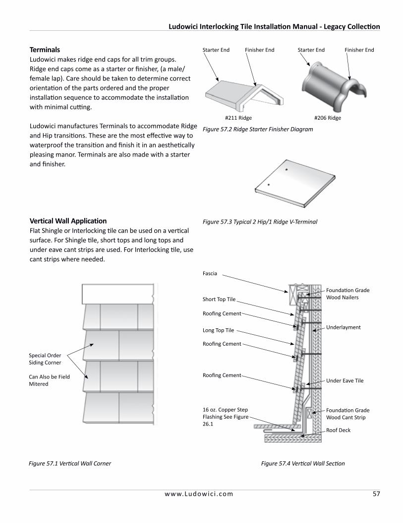
Ludowici Interlocking Tile Installation Manual - Legacy Collection
57www.Ludowic i .com
Figure 41.2 Left Rake Step Flashing
TerminalsLudowici makes ridge end caps for all trim groups. Ridge end caps come as a starter or finisher, (a male/female lap). Care should be taken to determine correct orientation of the parts ordered and the proper installation sequence to accommodate the installation with minimal cutting.
Ludowici manufactures Terminals to accommodate Ridge and Hip transitions. These are the most effective way to waterproof the transition and finish it in an aesthetically pleasing manor. Terminals are also made with a starter and finisher.
Figure 57.1 Vertical Wall Corner
Vertical Wall ApplicationFlat Shingle or Interlocking tile can be used on a vertical surface. For Shingle tile, short tops and long tops and under eave cant strips are used. For Interlocking tile, use cant strips where needed.
Special Order Siding Corner
Can Also be Field Mitered
Figure 57.4 Vertical Wall Section
Fascia
Short Top Tile
Roofing Cement
Long Top Tile
Roofing Cement
Roofing Cement
16 oz. Copper Step Flashing See Figure 26.1
Foundation Grade Wood Nailers
Underlayment
Under Eave Tile
Foundation Grade Wood Cant Strip
Roof Deck
Figure 57.2 Ridge Starter Finisher Diagram
Figure 57.3 Typical 2 Hip/1 Ridge V-Terminal
Starter End Finisher EndStarter End Finisher End
#211 Ridge #206 Ridge

Ludowici Interlocking Tile Installation Manual - Legacy Collection
58 www.Ludowic i .com
Staggered ApplicationLudoSlate™ and LudoShake™ can be laid with staggered butts to achieve a more rustic appearance.
The roofer will need to snap off the waterlock knockouts on both the lower left corner and the upper right corner to allow the tiles to be laid staggered.
Strike the chalk lines in the same method as a standard installation. Lay the first course in a straight line. On the second and above courses lay the tiles on the chalk line and randomly drop some up to 3/4" below the chalk line to achieve the random staggered look.
Figure 58.3 Staggered Layout
Nip Off the Waterlock Knock Out to Allow Staggered Lay Up
Nip Off the Waterlock Knock Out to Allow Staggered Lay Up
Figure 58.2 Staggered Tile Prep
First Row of Tiles Installed With No Stagger
Snow GuardsSnow guards are generally required in areas where snow and ice may accumulate on the roof. Snow guards are sometimes used on sloped roofs to prevent a mass of snow or ice from sliding off the roofs and injuring persons, damaging gutters or plants and blocking walks and driveways. Snow guards hold the snow in place above the eaves until it can melt and the water runs off.
It is recommended that snow guards should be installed on at least 3 or 4 courses, offset from course to course, spaced in staggered interval rows. Begin with the third or fourth row. However, spacing and quantity of snow guards is a matter of judgement based on local weather conditions (see Figure 60.1).
Alpine conditions will require a professional engineer to design the required snow retainage system. Tile should not be exposed to ice and snow loads exceeding 100 pounds per square foot.
A snow guard must be made of nonferrous material to prevent possible rust stains.
Figure 58.1 Snow Guard Spacing
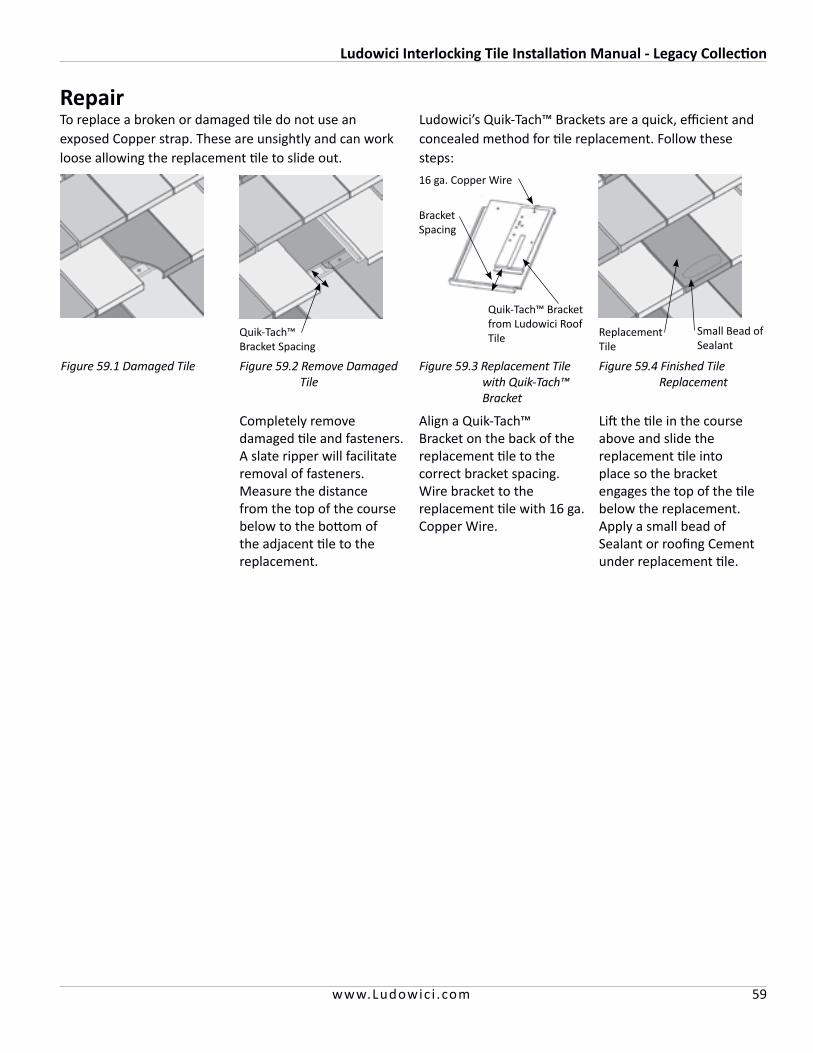
Ludowici Interlocking Tile Installation Manual - Legacy Collection
59www.Ludowic i .com
RepairTo replace a broken or damaged tile do not use an exposed Copper strap. These are unsightly and can work loose allowing the replacement tile to slide out.
Completely remove damaged tile and fasteners. A slate ripper will facilitate removal of fasteners. Measure the distance from the top of the course below to the bottom of the adjacent tile to the replacement.
Align a Quik-Tach™ Bracket on the back of the replacement tile to the correct bracket spacing. Wire bracket to the replacement tile with 16 ga. Copper Wire.
Lift the tile in the course above and slide the replacement tile into place so the bracket engages the top of the tile below the replacement. Apply a small bead of Sealant or roofing Cement under replacement tile.
Quik-Tach™ Bracket Spacing
Replacement Tile
Small Bead of Sealant
Figure 59.3 Replacement Tile with Quik-Tach™ Bracket
Figure 59.2 Remove Damaged Tile
Figure 59.1 Damaged Tile
Ludowici’s Quik-Tach™ Brackets are a quick, efficient and concealed method for tile replacement. Follow these steps:
Figure 59.4 Finished Tile Replacement
Quik-Tach™ Bracket from Ludowici Roof Tile
16 ga. Copper Wire
Bracket Spacing
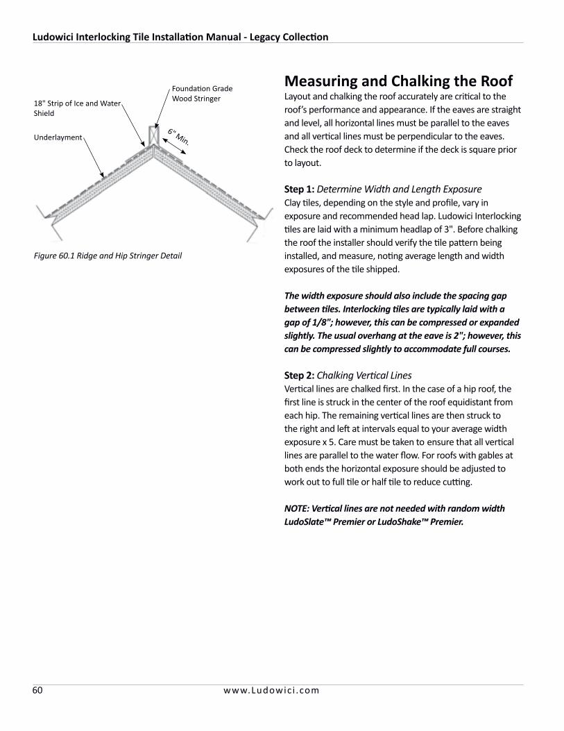
Ludowici Interlocking Tile Installation Manual - Legacy Collection
60 www.Ludowic i .com
Measuring and Chalking the Roof Layout and chalking the roof accurately are critical to the roof’s performance and appearance. If the eaves are straight and level, all horizontal lines must be parallel to the eaves and all vertical lines must be perpendicular to the eaves. Check the roof deck to determine if the deck is square prior to layout.
Step 1: Determine Width and Length Exposure Clay tiles, depending on the style and profile, vary in exposure and recommended head lap. Ludowici Interlocking tiles are laid with a minimum headlap of 3". Before chalking the roof the installer should verify the tile pattern being installed, and measure, noting average length and width exposures of the tile shipped.
The width exposure should also include the spacing gap between tiles. Interlocking tiles are typically laid with a gap of 1/8"; however, this can be compressed or expanded slightly. The usual overhang at the eave is 2"; however, this can be compressed slightly to accommodate full courses.
Step 2: Chalking Vertical Lines Vertical lines are chalked first. In the case of a hip roof, the first line is struck in the center of the roof equidistant from each hip. The remaining vertical lines are then struck to the right and left at intervals equal to your average width exposure x 5. Care must be taken to ensure that all vertical lines are parallel to the water flow. For roofs with gables at both ends the horizontal exposure should be adjusted to work out to full tile or half tile to reduce cutting.
NOTE: Vertical lines are not needed with random width LudoSlate™ Premier or LudoShake™ Premier.
Figure 60.1 Ridge and Hip Stringer Detail
Underlayment
18" Strip of Ice and Water Shield
Foundation Grade Wood Stringer
6" Min.
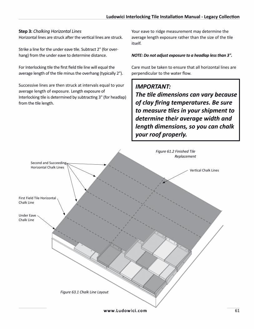
Ludowici Interlocking Tile Installation Manual - Legacy Collection
61www.Ludowic i .com
Step 3: Chalking Horizontal Lines Horizontal lines are struck after the vertical lines are struck.
Strike a line for the under eave tile. Subtract 2" (for over-hang) from the under eave to determine distance.
For Interlocking tile the first field tile line will equal the average length of the tile minus the overhang (typically 2").
Successive lines are then struck at intervals equal to your average length of exposure. Length exposure of Interlocking tile is determined by subtracting 3" (for headlap) from the tile length.
IMPORTANT:The tile dimensions can vary because of clay firing temperatures. Be sure to measure tiles in your shipment to determine their average width and length dimensions, so you can chalk your roof properly.
www.Ludowic i .com
Your eave to ridge measurement may determine the average length exposure rather than the size of the tile itself.
NOTE: Do not adjust exposure to a headlap less than 3".
Care must be taken to ensure that all horizontal lines are perpendicular to the water flow.
Figure 63.1 Chalk Line Layout
Vertical Chalk Lines
First Field Tile Horizontal Chalk Line
Second and Succeeding Horizontal Chalk Lines
Under Eave Chalk Line
Figure 61.2 Finished Tile Replacement
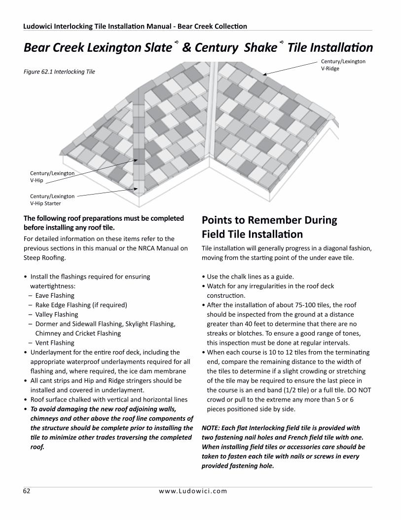
Ludowici Interlocking Tile Installation Manual - Bear Creek Collection
62 www.Ludowic i .com
Bear Creek Lexington Slate® & Century Shake® Tile Installation
NOTE: Each flat Interlocking field tile is provided with two fastening nail holes and French field tile with one. When installing field tiles or accessories care should be taken to fasten each tile with nails or screws in every provided fastening hole.
The following roof preparations must be completed before installing any roof tile. For detailed information on these items refer to the previous sections in this manual or the NRCA Manual on Steep Roofing.
• Install the flashings required for ensuring watertightness: – Eave Flashing – Rake Edge Flashing (if required) – Valley Flashing – Dormer and Sidewall Flashing, Skylight Flashing,
Chimney and Cricket Flashing – Vent Flashing• Underlayment for the entire roof deck, including the
appropriate waterproof underlayments required for all flashing and, where required, the ice dam membrane
• All cant strips and Hip and Ridge stringers should be installed and covered in underlayment.
• Roof surface chalked with vertical and horizontal lines• To avoid damaging the new roof adjoining walls,
chimneys and other above the roof line components of the structure should be complete prior to installing the tile to minimize other trades traversing the completed roof.
Points to Remember During Field Tile InstallationTile installation will generally progress in a diagonal fashion, moving from the starting point of the under eave tile.
• Use the chalk lines as a guide.• Watch for any irregularities in the roof deck
construction.• After the installation of about 75-100 tiles, the roof
should be inspected from the ground at a distance greater than 40 feet to determine that there are no streaks or blotches. To ensure a good range of tones, this inspection must be done at regular intervals.
• When each course is 10 to 12 tiles from the terminating end, compare the remaining distance to the width of the tiles to determine if a slight crowding or stretching of the tile may be required to ensure the last piece in the course is an end band (1/2 tile) or a full tile. DO NOT crowd or pull to the extreme any more than 5 or 6 pieces positioned side by side.
Century/Lexington V-Ridge
Century/LexingtonV-Hip Starter
Century/LexingtonV-Hip
Figure 62.1 Interlocking Tile
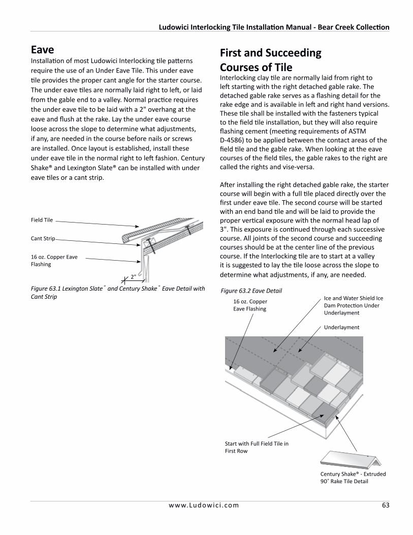
Ludowici Interlocking Tile Installation Manual - Bear Creek Collection
63www.Ludowic i .com
Eave Installation of most Ludowici Interlocking tile patterns require the use of an Under Eave Tile. This under eave tile provides the proper cant angle for the starter course. The under eave tiles are normally laid right to left, or laid from the gable end to a valley. Normal practice requires the under eave tile to be laid with a 2" overhang at the eave and flush at the rake. Lay the under eave course loose across the slope to determine what adjustments, if any, are needed in the course before nails or screws are installed. Once layout is established, install these under eave tile in the normal right to left fashion. Century Shake® and Lexington Slate® can be installed with under eave tiles or a cant strip.
Figure 63.2 Eave Detail
16 oz. Copper Eave Flashing
Ice and Water Shield Ice Dam Protection Under Underlayment
Start with Full Field Tile in First Row
Underlayment
First and Succeeding Courses of TileInterlocking clay tile are normally laid from right to left starting with the right detached gable rake. The detached gable rake serves as a flashing detail for the rake edge and is available in left and right hand versions. These tile shall be installed with the fasteners typical to the field tile installation, but they will also require flashing cement (meeting requirements of ASTM D-4586) to be applied between the contact areas of the field tile and the gable rake. When looking at the eave courses of the field tiles, the gable rakes to the right are called the rights and vise-versa.
After installing the right detached gable rake, the starter course will begin with a full tile placed directly over the first under eave tile. The second course will be started with an end band tile and will be laid to provide the proper vertical exposure with the normal head lap of 3". This exposure is continued through each successive course. All joints of the second course and succeeding courses should be at the center line of the previous course. If the Interlocking tile are to start at a valley it is suggested to lay the tile loose across the slope to determine what adjustments, if any, are needed.
Figure 63.1 Lexington Slate® and Century Shake® Eave Detail with Cant Strip
Field Tile
16 oz. Copper Eave Flashing
Cant Strip
2"
Century Shake® - Extruded 90˚ Rake Tile Detail
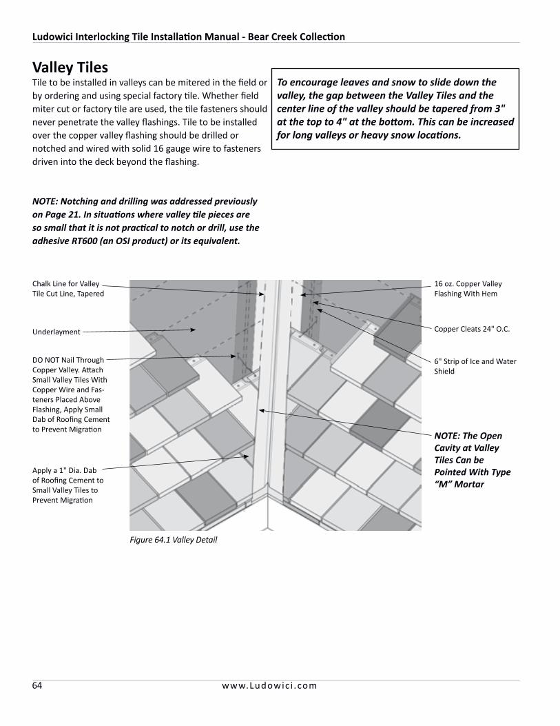
Ludowici Interlocking Tile Installation Manual - Bear Creek Collection
64 www.Ludowic i .com
Valley TilesTile to be installed in valleys can be mitered in the field or by ordering and using special factory tile. Whether field miter cut or factory tile are used, the tile fasteners should never penetrate the valley flashings. Tile to be installed over the copper valley flashing should be drilled or notched and wired with solid 16 gauge wire to fasteners driven into the deck beyond the flashing.
NOTE: Notching and drilling was addressed previously on Page 21. In situations where valley tile pieces are so small that it is not practical to notch or drill, use the adhesive RT600 (an OSI product) or its equivalent.
Figure 64.1 Valley Detail
16 oz. Copper Valley Flashing With Hem
Copper Cleats 24" O.C.
6" Strip of Ice and Water Shield
Underlayment
DO NOT Nail Through Copper Valley. Attach Small Valley Tiles With Copper Wire and Fas-teners Placed Above Flashing, Apply Small Dab of Roofing Cement to Prevent Migration
Apply a 1" Dia. Dab of Roofing Cement to Small Valley Tiles to Prevent Migration
To encourage leaves and snow to slide down the valley, the gap between the Valley Tiles and the center line of the valley should be tapered from 3" at the top to 4" at the bottom. This can be increased for long valleys or heavy snow locations.
Chalk Line for Valley Tile Cut Line, Tapered
NOTE: The Open Cavity at Valley Tiles Can be Pointed With Type “M” Mortar
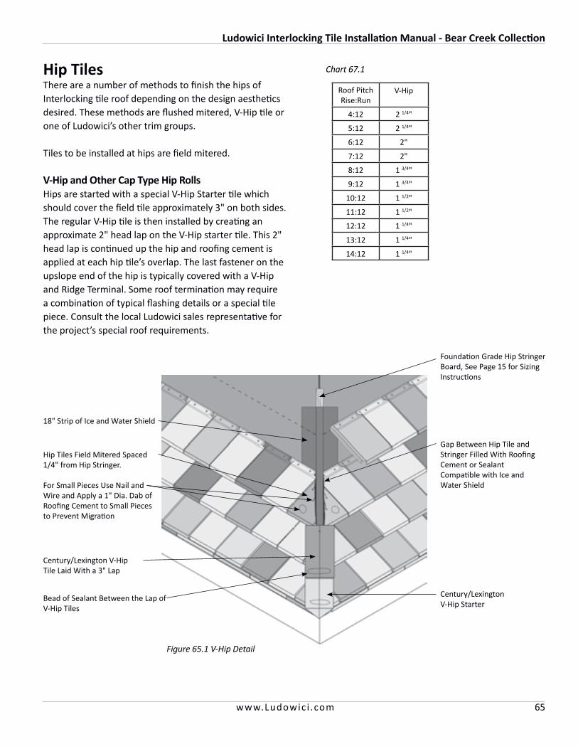
Ludowici Interlocking Tile Installation Manual - Bear Creek Collection
65www.Ludowic i .com
Hip TilesThere are a number of methods to finish the hips of Interlocking tile roof depending on the design aestheticsdesired. These methods are flushed mitered, V-Hip tile or one of Ludowici’s other trim groups.
Tiles to be installed at hips are field mitered.
V-Hip and Other Cap Type Hip RollsHips are started with a special V-Hip Starter tile which should cover the field tile approximately 3" on both sides. The regular V-Hip tile is then installed by creating an approximate 2" head lap on the V-Hip starter tile. This 2" head lap is continued up the hip and roofing cement is applied at each hip tile’s overlap. The last fastener on the upslope end of the hip is typically covered with a V-Hip and Ridge Terminal. Some roof termination may require a combination of typical flashing details or a special tile piece. Consult the local Ludowici sales representative for the project’s special roof requirements.
Figure 65.1 V-Hip Detail
Foundation Grade Hip Stringer Board, See Page 15 for Sizing Instructions
18" Strip of Ice and Water Shield
Hip Tiles Field Mitered Spaced 1/4" from Hip Stringer.
For Small Pieces Use Nail and Wire and Apply a 1" Dia. Dab of Roofing Cement to Small Pieces to Prevent Migration
Gap Between Hip Tile and Stringer Filled With Roofing Cement or Sealant Compatible with Ice and Water Shield
Century/Lexington V-Hip Tile Laid With a 3" Lap
Bead of Sealant Between the Lap of V-Hip Tiles
Century/Lexington V-Hip Starter
Roof PitchRise:Run
V-Hip
4:12 2 1/4"
5:12 2 1/4"
6:12 2"
7:12 2"
8:12 1 3/4"
9:12 1 3/4"
10:12 1 1/2"
11:12 1 1/2"
12:12 1 1/4"
13:12 1 1/4"
14:12 1 1/4"
Chart 67.1
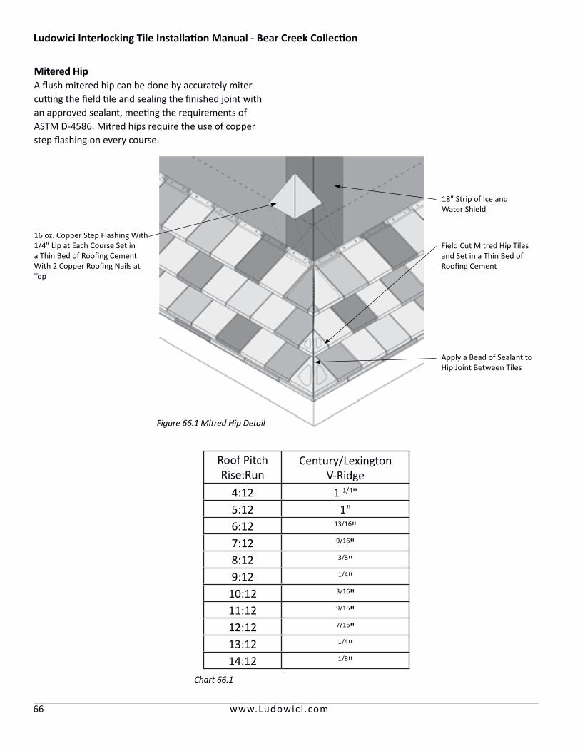
Ludowici Interlocking Tile Installation Manual - Bear Creek Collection
66 www.Ludowic i .com
Mitered HipA flush mitered hip can be done by accurately miter-cutting the field tile and sealing the finished joint with an approved sealant, meeting the requirements of ASTM D-4586. Mitred hips require the use of copper step flashing on every course.
18" Strip of Ice and Water Shield
16 oz. Copper Step Flashing With 1/4" Lip at Each Course Set in a Thin Bed of Roofing Cement With 2 Copper Roofing Nails at Top
Field Cut Mitred Hip Tiles and Set in a Thin Bed of Roofing Cement
Apply a Bead of Sealant to Hip Joint Between Tiles
Figure 66.1 Mitred Hip Detail
Roof PitchRise:Run
Century/Lexington V-Ridge
4:12 1 1/4"5:12 1"6:12 13/16"7:12 9/16"8:12 3/8"9:12 1/4"
10:12 3/16"11:12 9/16"12:12 7/16"13:12 1/4"14:12 1/8"
Chart 66.1
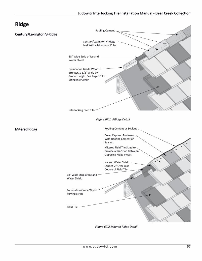
Ludowici Interlocking Tile Installation Manual - Bear Creek Collection
67www.Ludowic i .com
Century/Lexington V-Ridge
Ridge
Figure 67.1 V-Ridge Detail
Century/Lexington V-Ridge Laid With a Minimum 2" Lap
Roofing Cement
Foundation Grade Wood Stringer, 1-1/2" Wide by Proper Height. See Page 15 for Sizing Instruction
18" Wide Strip of Ice and Water Shield
Interlocking Filed Tile
Mitered Ridge
Figure 67.2 Mitered Ridge Detail
18" Wide Strip of Ice and Water Shield
Ice and Water Shield Lapped 2" Over Last Course of Field Tile
Foundation Grade Wood Furring Strips
Field Tile
Cover Exposed Fasteners With Roofing Cement or Sealant
Mitered Field Tile Sized to Provide a 1/4" Gap Between Opposing Ridge Pieces
Roofing Cement or Sealant
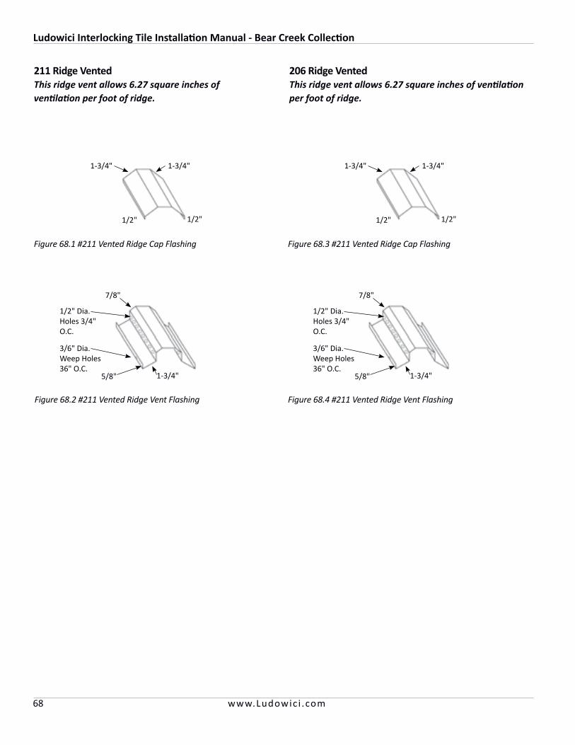
Ludowici Interlocking Tile Installation Manual - Bear Creek Collection
68 www.Ludowic i .com
211 Ridge VentedThis ridge vent allows 6.27 square inches of ventilation per foot of ridge.
Figure 68.1 #211 Vented Ridge Cap Flashing
Figure 68.2 #211 Vented Ridge Vent Flashing
1/2"
1-3/4"1-3/4"
1/2"
5/8" 1-3/4"
7/8"
1/2" Dia. Holes 3/4" O.C.
3/6" Dia. Weep Holes36" O.C.
206 Ridge VentedThis ridge vent allows 6.27 square inches of ventilation per foot of ridge.
Figure 68.3 #211 Vented Ridge Cap Flashing
Figure 68.4 #211 Vented Ridge Vent Flashing
1/2"
1-3/4"1-3/4"
1/2"
5/8" 1-3/4"
7/8"
1/2" Dia. Holes 3/4" O.C.
3/6" Dia. Weep Holes36" O.C.
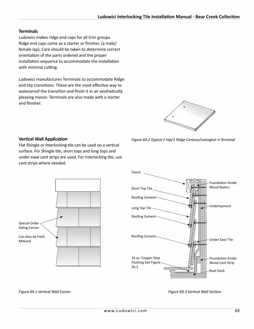
Ludowici Interlocking Tile Installation Manual - Bear Creek Collection
69www.Ludowic i .com
TerminalsLudowici makes ridge end caps for all trim groups. Ridge end caps come as a starter or finisher, (a male/female lap). Care should be taken to determine correct orientation of the parts ordered and the proper installation sequence to accommodate the installation with minimal cutting.
Ludowici manufactures Terminals to accommodate Ridge and Hip transitions. These are the most effective way to waterproof the transition and finish it in an aesthetically pleasing manor. Terminals are also made with a starter and finisher.
Figure 69.1 Vertical Wall Corner
Vertical Wall ApplicationFlat Shingle or Interlocking tile can be used on a vertical surface. For Shingle tile, short tops and long tops and under eave cant strips are used. For Interlocking tile, use cant strips where needed.
Special Order Siding Corner
Can Also be Field Mitered
Figure 69.3 Vertical Wall Section
Fascia
Short Top Tile
Roofing Cement
Long Top Tile
Roofing Cement
Roofing Cement
16 oz. Copper Step Flashing See Figure 26.1
Foundation Grade Wood Nailers
Underlayment
Under Eave Tile
Foundation Grade Wood Cant Strip
Roof Deck
Figure 69.2 Typical 2 Hip/1 Ridge Century/Lexington V-Terminal

Ludowici Interlocking Tile Installation Manual - Bear Creek Collection
70 www.Ludowic i .com
Snow GuardsSnow guards are generally required in areas where snow and ice may accumulate on the roof. Snow guards are sometimes used on sloped roofs to prevent a mass of snow or ice from sliding off the roofs and injuring persons, damaging gutters or plants and blocking walks and driveways. Snow guards hold the snow in place above the eaves until it can melt and the water runs off.
It is recommended that snow guards should be installed on at least 3 or 4 courses, offset from course to course, spaced in staggered interval rows. Begin with the third or fourth row. However, spacing and quantity of snow guards is a matter of judgement based on local weather conditions (see Figure 75.1).
Alpine conditions will require a professional engineer to design the required snow retainage system. Tile should not be exposed to ice and snow loads exceeding 100 pounds per square foot.
A snow guard must be made of nonferrous material to prevent possible rust stains.
Figure 70.1 Snow Guard Spacing
RepairTo replace a broken or damaged tile do not use an exposed Copper strap. These are unsightly and can work loose allowing the replacement tile to slide out.
Completely remove damaged tile and fasteners. A slate ripper will facilitate removal of fasteners. Measure the distance from the top of the course below to the bottom of the adjacent tile to the replacement.
Align a Quik-Tach™ Bracket on the back of the replacement tile to the correct bracket spacing. Wire bracket to the replacement tile with 16 ga. Copper Wire.
Lift the tile in the course above and slide the replacement tile into place so the bracket engages the top of the tile below the replacement. Apply a small bead of Sealant or roofing Cement under replacement tile.
Quik-Tach™ Bracket Spacing
Replacement Tile
Small Bead of Sealant
Figure 71.3 Replacement Tile with Quik-Tach™ Bracket
Figure 71.2 Remove Damaged Tile
Figure 71.1 Damaged Tile
Ludowici’s Quik-Tach™ Brackets are a quick, efficient and concealed method for tile replacement. Follow these steps:
Figure 71.4 Finished Tile Replacement
Quik-Tach™ Bracket from Ludowici Roof Tile
16 ga. Copper Wire
Bracket Spacing
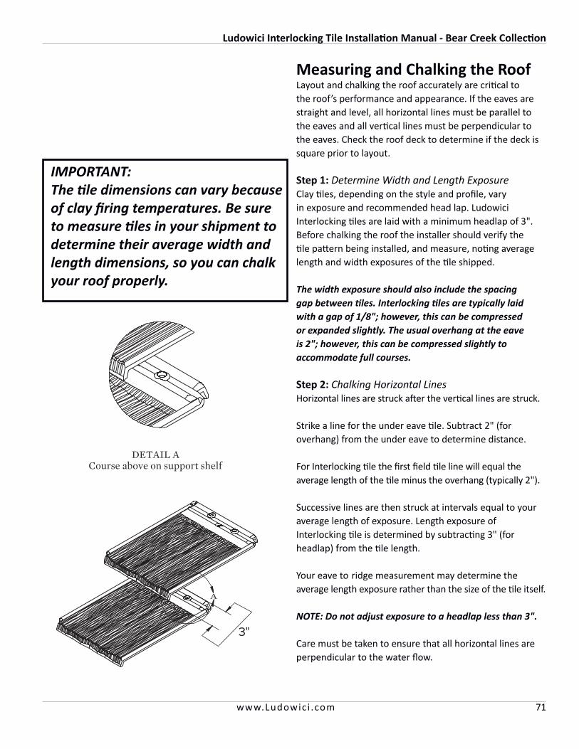
Ludowici Interlocking Tile Installation Manual - Bear Creek Collection
71www.Ludowic i .com
Measuring and Chalking the Roof Layout and chalking the roof accurately are critical to the roof’s performance and appearance. If the eaves are straight and level, all horizontal lines must be parallel to the eaves and all vertical lines must be perpendicular to the eaves. Check the roof deck to determine if the deck is square prior to layout.
Step 1: Determine Width and Length Exposure Clay tiles, depending on the style and profile, vary in exposure and recommended head lap. Ludowici Interlocking tiles are laid with a minimum headlap of 3". Before chalking the roof the installer should verify the tile pattern being installed, and measure, noting average length and width exposures of the tile shipped.
The width exposure should also include the spacing gap between tiles. Interlocking tiles are typically laid with a gap of 1/8"; however, this can be compressed or expanded slightly. The usual overhang at the eave is 2"; however, this can be compressed slightly to accommodate full courses.
Step 2: Chalking Horizontal Lines Horizontal lines are struck after the vertical lines are struck.
Strike a line for the under eave tile. Subtract 2" (for overhang) from the under eave to determine distance.
For Interlocking tile the first field tile line will equal the average length of the tile minus the overhang (typically 2").
Successive lines are then struck at intervals equal to your average length of exposure. Length exposure of Interlocking tile is determined by subtracting 3" (for headlap) from the tile length.
Your eave to ridge measurement may determine the average length exposure rather than the size of the tile itself.
NOTE: Do not adjust exposure to a headlap less than 3".
Care must be taken to ensure that all horizontal lines are perpendicular to the water flow.
IMPORTANT:The tile dimensions can vary because of clay firing temperatures. Be sure to measure tiles in your shipment to determine their average width and length dimensions, so you can chalk your roof properly.

Ludowici Roof Tile, Inc.4757 Tile Plant Rd.
P.O. Box 69New Lexington, OH 43764
1-800-945-8453www.Ludowici.com
Have a question about how to install Ludowici tile?
Contact your local Ludowici Sales Representative or the Ludowici Technical Service Department at
1-800-945-8453
This manual includes the basic installation instructions from start to finish in an easy-to-read format. However, the applicator must always give consideration to
regional climactic conditions and code requirements.
For Alpine or Tropical installations contact the Ludowici Technical Service Department for assistance.
LRT-436-0816© 2016 Ludowici Roof Tile, Inc.