Embed Size (px)
Citation preview
Interleaved Multi-Cell Isolated Three-Phase PWM Rectifier System for Aircraft Applications
M. Silva, N. Hensgens, J.M. Molina, M. Vasic, J. Oliver, P. Alou, Ó. Garcia, and J. A. Cobos
Abstract—Recently there has been an important increase in electric equipment, as well as, electric power demand in aircrafts applications. This prompts to the necessity of efficient, reliable, and low-weight converters, especially rectifiers from 115VAC to 270VDC because these voltages are used in power distribution. In order to obtain a high efficiency, in aircraft application where the derating in semiconductors is high, normally several semiconductors are used in parallel to decrease the conduction losses. However, this is in conflict with high reliability. To match both goals of high efficiency and reliability, this work proposes an interleaved multi-cell rectifier system, employing several converter cells in parallel instead of parallel-connected semiconductors. In this work a lOkW multi-cell isolated rectifier system has been designed where each cell is composed of a buck type rectifier and a full bridge DC-DC converter. The implemented system exhibits 91% of efficiency, high power density (10kW/10kg), low THD (2.5%), and n-1 fault tolerance which complies, with military aircraft standards.
I. INTRODUCTION
During the last decade the More Electric Aircraft (MEA) concept has been gaining more and more relevance both in the industrial and military aircraft world [1]. This has been caused by the replacement of pneumatic, mechanic, and hydraulic actuators by electric actuators. With this change, the reliability of the system is increased and the maintenance is reduced. Furthermore, the losses in the energy conversion are minimized, causing an increment in the overall efficiency.
All these innovations have increased the demand of electrical power in airplanes, which has prompted the incorporation of a new level of distribution power in military aircrafts. The classical aircraft distribution is a three-phase grid with 115VAC at 400Hz and 28VDC direct current grid. The new high DC voltage distribution is 270VDC. The main benefit of using a high voltage is that it decreases the current level to 10 times lower than the traditional low voltage; hence, the section and the weight of the cabling is considerably reduced [2]-[6]
In a typical aircraft, power generators provide three phase grid of 115VAC. The simplest way to obtain 270VDC is using a diode bridge; however, in this way the total harmonic distortion of the grid current (THDj) is around 30% [7], which is unacceptable in aircraft applications. In order, to obtain low THD, high power density, and control capability of the output voltage, an active rectifier needs to be used.
Within the active rectifiers there are two families, the buck type and the boost type [8]. Since the DC voltage obtained
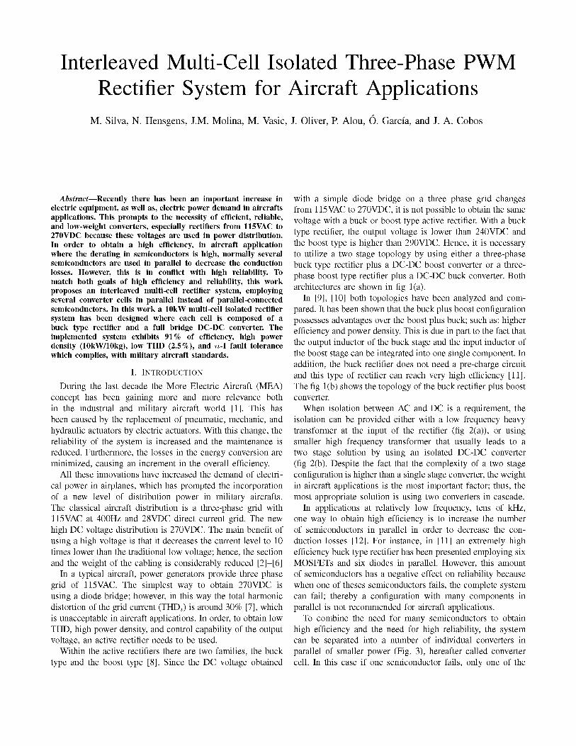
with a simple diode bridge on a three phase grid changes from 115 VAC to 270VDC, it is not possible to obtain the same voltage with a buck or boost type active rectifier. With a buck type rectifier, the output voltage is lower than 240VDC and the boost type is higher than 290VDC. Hence, it is necessary to utilize a two stage topology by using either a three-phase buck type rectifier plus a DC-DC boost converter or a three-phase boost type rectifier plus a DC-DC buck converter. Both architectures are shown in fig 1(a).
In [9], [10] both topologies have been analyzed and compared. It has been shown that the buck plus boost configuration possesses advantages over the boost plus buck; such as; higher efficiency and power density. This is due in part to the fact that the output inductor of the buck stage and the input inductor of the boost stage can be integrated into one single component. In addition, the buck rectifier does not need a pre-charge circuit and this type of rectifier can reach very high efficiency [11]. The fig 1(b) shows the topology of the buck rectifier plus boost converter.
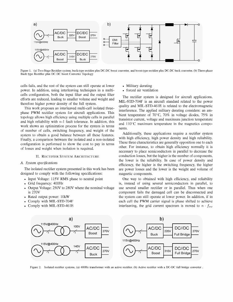
When isolation between AC and DC is a requirement, the isolation can be provided either with a low frequency heavy transformer at the input of the rectifier (fig 2(a)), or using smaller high frequency transformer that usually leads to a two stage solution by using an isolated DC-DC converter (fig 2(b). Despite the fact that the complexity of a two stage configuration is higher than a single stage converter, the weight in aircraft applications is the most important factor; thus, the most appropriate solution is using two converters in cascade.
In applications at relatively low frequency, tens of kHz, one way to obtain high efficiency is to increase the number of semiconductors in parallel in order to decrease the conduction losses [12]. For instance, in [11] an extremely high efficiency buck type rectifier has been presented employing six MOSFETs and six diodes in parallel. However, this amount of semiconductors has a negative effect on reliability because when one of theses semiconductors fails, the complete system can fail; thereby a configuration with many components in parallel is not recommended for aircraft applications.
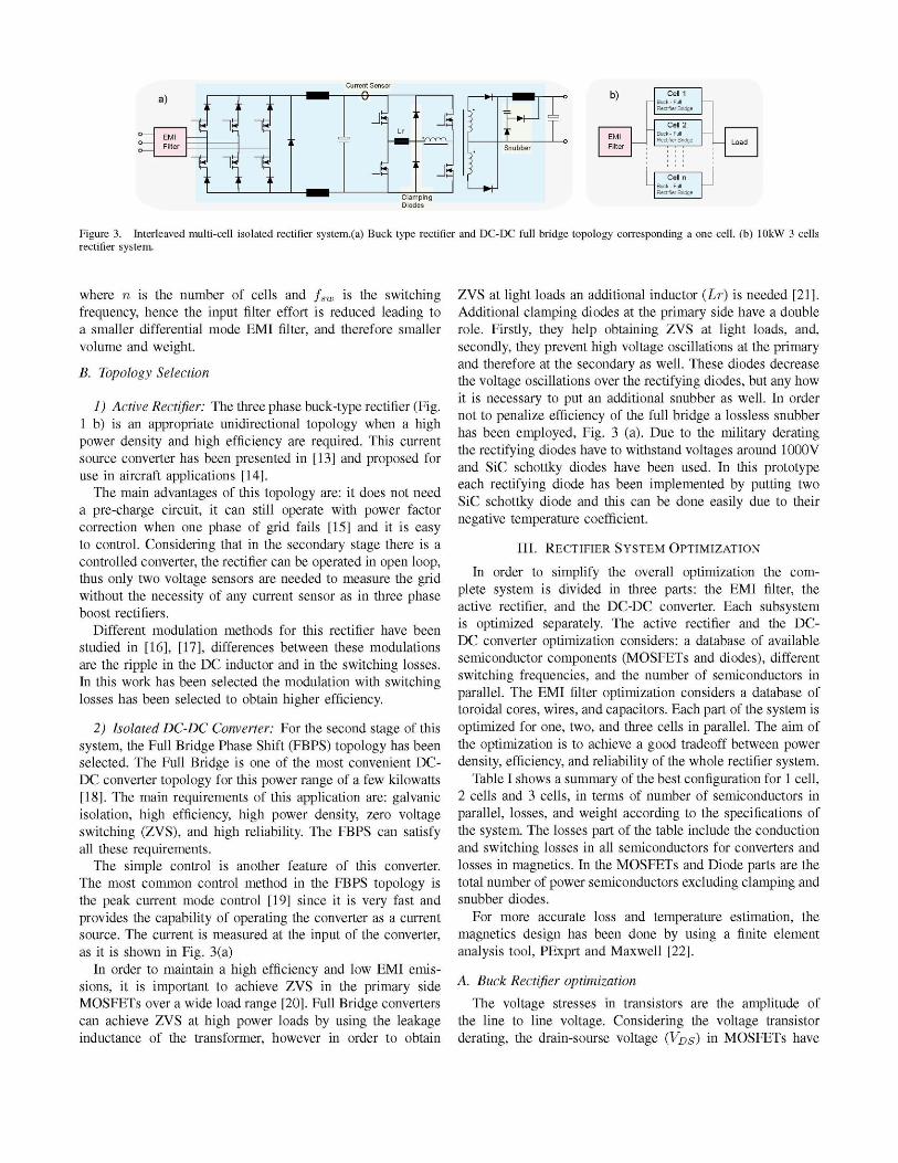
To combine the need for many semiconductors to obtain high efficiency and the need for high reliability, the system can be separated into a number of individual converters in parallel of smaller power (Fig. 3), hereafter called converter cell. In this case if one semiconductor fails, only one of the
a)
115V@400Hz
115V@400Hz
AC/DC Buck
AC/DC Boost
DC/DC Boost
DC/DC Buck
b)
EMI Filter
1
1
1
1
1
1 J
• I i—o
Figure 1. (a) Two-Stage Rectifier system, buck-type rectifier plus DC-DC boost converter, and boost-type rectifier plus DC-DC buck converter, (b) Three-phase Buck type Rectifier plus DC-DC boost Converter Topology
cells fails, and the rest of the system can still operate at lower power. In addition, using interleaving techniques in a multi-cells configuration, both the input filter and the output filter efforts are reduced, leading to smaller volume and weight and therefore higher power density of the full system.
This work proposes an interleaved multi-cell isolated three-phase PWM rectifier system for aircraft applications. This topology allows high efficiency using multiple cells in parallel and high reliability with n-\ fault tolerance. In addition, this work shows an optimization process for the system in terms of number of cells, switching frequency, and weight of the system to obtain a good balance between all these features. Finally, a comparison between the isolated and a non-isolated configuration is performed to show the cost to pay in terms of losses and weight when isolation is required.
II. RECTIFIER SYSTEM ARCHITECTURE
A. System specifications
The isolated rectifier system presented in this work has been designed to comply with the following specifications:
• Input Voltage: 115V RMS phase to neutral point • Grid frequency: 400Hz • Output Voltage: 250V to 280V where the nominal voltage
is 270V • Rated output power: lOkW . Comply with MIL-STD-704F . Comply with MIL-STD-461E
. Military derating • forced air ventilation
The rectifier system is designed for aircraft applications. MIL-STD-704F is an aircraft standard related to the power quality and MIL-STD-461E is related to the electromagnetic interference. The applied military derating considers: an ambient temperature of 70° C, 70% in voltage diodes, 75% in transistor current, voltage and maximum junction temperature and 110°C maximum temperature in the magnetics components.
Additionally, these applications require a rectifier system with high efficiency, high power density and high reliability. These three characteristics are generally opposition one to each other. For instance, to obtain high efficiency normally it is necessary to place semiconductors in parallel to decrease the conduction losses, but the higher is the number of components, the lower is the reliability. In case of power density and efficiency, the higher is the switching frequency, the higher are power losses and the lower is the weight and volume of magnetic components.
One way to obtained with high efficiency, and reliability is, instead of using several semiconductors in parallel, to use several smaller rectifier or in parallel. Thus when one component fails the damaged cell can be disconnected and the system can still operate at lower power. In addition, if in each cell the PWM carrier signal is phase shifted to achieve interleaving, the grid current spectrum is moved to n • fsw
a) 115V@400Hz
(5M£> 115V@400Hz
(5H3D-
100V \ X
I '*
140V \ ) ^
AC/DC Boost
AC/DC Buck
270V
115V@400Hz
b)
AC/DC Buck
AC/DC Boost
220V
310V
DC//DC Full Bridge
DC//DC Full Bridge
270V
270V
Figure 2. Isolated rectifier systems, (a) 400Hz transformer with an active rectifier, (b) Active rectifier with a DC-DC full bridge converter .
a)
EMI Filter
E
~H
~e ~g
i s ~E
Current Sensor
— 9 -
-q " J
J -$ Clamping Diodes
EMI Filter
Figure 3. Interleaved multi-cell isolated rectifier system.(a) Buck type rectifier and DC-DC full bridge topology corresponding a one cell, (b) lOkW 3 cells rectifier system.
where n is the number of cells and fsw is the switching frequency, hence the input filter effort is reduced leading to a smaller differential mode EMI filter, and therefore smaller volume and weight.
B. Topology Selection
1) Active Rectifier: The three phase buck-type rectifier (Fig. 1 b) is an appropriate unidirectional topology when a high power density and high efficiency are required. This current source converter has been presented in [13] and proposed for use in aircraft applications [14].
The main advantages of this topology are: it does not need a pre-charge circuit, it can still operate with power factor correction when one phase of grid fails [15] and it is easy to control. Considering that in the secondary stage there is a controlled converter, the rectifier can be operated in open loop, thus only two voltage sensors are needed to measure the grid without the necessity of any current sensor as in three phase boost rectifiers.
Different modulation methods for this rectifier have been studied in [16], [17], differences between these modulations are the ripple in the DC inductor and in the switching losses. In this work has been selected the modulation with switching losses has been selected to obtain higher efficiency.
2) Isolated DC-DC Converter: For the second stage of this system, the Full Bridge Phase Shift (FBPS) topology has been selected. The Full Bridge is one of the most convenient DC-DC converter topology for this power range of a few kilowatts [18]. The main requirements of this application are: galvanic isolation, high efficiency, high power density, zero voltage switching (ZVS), and high reliability. The FBPS can satisfy all these requirements.
The simple control is another feature of this converter. The most common control method in the FBPS topology is the peak current mode control [19] since it is very fast and provides the capability of operating the converter as a current source. The current is measured at the input of the converter, as it is shown in Fig. 3(a)
In order to maintain a high efficiency and low EMI emissions, it is important to achieve ZVS in the primary side MOSFETs over a wide load range [20]. Full Bridge converters can achieve ZVS at high power loads by using the leakage inductance of the transformer, however in order to obtain
ZVS at light loads an additional inductor (Lr) is needed [21]. Additional clamping diodes at the primary side have a double role. Firstly, they help obtaining ZVS at light loads, and, secondly, they prevent high voltage oscillations at the primary and therefore at the secondary as well. These diodes decrease the voltage oscillations over the rectifying diodes, but any how it is necessary to put an additional snubber as well. In order not to penalize efficiency of the full bridge a lossless snubber has been employed, Fig. 3 (a). Due to the military derating the rectifying diodes have to withstand voltages around 1000V and SiC schottky diodes have been used. In this prototype each rectifying diode has been implemented by putting two SiC schottky diode and this can be done easily due to their negative temperature coefficient.
III. RECTIFIER SYSTEM OPTIMIZATION
In order to simplify the overall optimization the complete system is divided in three parts: the EMI filter, the active rectifier, and the DC-DC converter. Each subsystem is optimized separately. The active rectifier and the DC-DC converter optimization considers: a database of available semiconductor components (MOSFETs and diodes), different switching frequencies, and the number of semiconductors in parallel. The EMI filter optimization considers a database of toroidal cores, wires, and capacitors. Each part of the system is optimized for one, two, and three cells in parallel. The aim of the optimization is to achieve a good tradeoff between power density, efficiency, and reliability of the whole rectifier system.
Table I shows a summary of the best configuration for 1 cell, 2 cells and 3 cells, in terms of number of semiconductors in parallel, losses, and weight according to the specifications of the system. The losses part of the table include the conduction and switching losses in all semiconductors for converters and losses in magnetics. In the MOSFETs and Diode parts are the total number of power semiconductors excluding clamping and snubber diodes.
For more accurate loss and temperature estimation, the magnetics design has been done by using a finite element analysis tool, PExprt and Maxwell [22].
A. Buck Rectifier optimization
The voltage stresses in transistors are the amplitude of the line to line voltage. Considering the voltage transistor derating, the drain-sourse voltage (Vps) m MOSFETs have
Table I SUMMARY TABLE FOR WEIGHT AND LOSSES ESTIMATED FOR 1, 2 AND 3
CELLS CONFIGURATION.
N° Cells
1 Cell
2 Cell
3 Cell
Element Filter
AC-DC FBPS Filter
AC-DC FBPS
Filter AC-DC FBPS
Weight 4.3kg 1.54kg 5.3kg 2.5kg 1.0kg 1.7kg
2.9kg 1.04kg 1.4kg
Losses 79W
470W 373W 65W
404W 358W
38W 400W 331W
MOSFETs
18 32
24 32
18 36
Diodes
14 12
14 12
21 12
to be higher than 115A/6/0 .75 = 375V. CoolMOS transistors from Infineon provide excellent performance capability from 500V to 900V. The MOSFETs database considers the full family of these transistors where RDS varies from 37mQ to 500miX Table I show the results by using the best MOSFETs candidate from the database for each configuration.
In table I, from the point of view of the number of MOSFETs, three is the minimum number of MOSFETs for a single cell configuration to comply with the derating temperature in transistors (112°C). In the same way, for the two cell configuration at least two MOSFETs are required since MOSFETs temperature, however, the global number of MOSFETs is higher than the single cell configuration. In the case of a three cell configuration, parallel MOSFETs are not needed which is positive from the point of view of reliability; the total number of MOSFETs is lower than the two cell configuration and using three cells one failure tolerance is possible assuming lower output power.
In terms of the power density, one cell configuration is 50% heavier than two and three configuration. Two and three cell configurations provide practically the same weight in magnetic components leading to the same power density. In addition according to the losses the three cell configuration is slightly more efficient than two, and much more than single cell configuration.
According to the rectifier, three cell configuration is the best, due to the number of semiconductors, reliability, power density and efficiency.
B. Full Bridge optimization
As is shown in table I, the single cell solution needs at least 8 MOSFETs in parallel, two cells solution needs 4 MOSFETs and 3 cells configuration needs 3 MOSFETs in parallel to comply with the derating temperature in transistors. Regarding power losses and number of semiconductor there is not an important difference between all configuration, however in terms power density there are differences. The three cells configuration is the lightest, especially in compare with the single cell configuration.
From the point of view of the full bridge both the two cells and three cell configuration are continents, because both of them have similar power density and efficiency.
C. EMI filter optimization
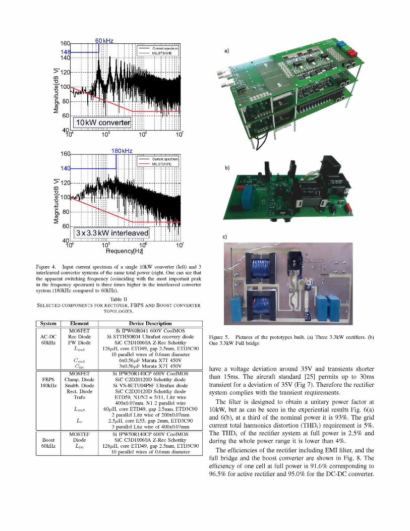
The EMI filter is one of the most important contributors to the overall weight and volume of the converter system [23]. This is due to the fact that it consists of large passive elements, i.e. shunt capacitors and series filter chokes for both common mode (CM) and differential mode (DM) noise. Since the goal is to obtain a system with low overall weight, an optimization of the filter is mandatory. Fig.4 shows the EMI spectrum of a single lOkW rectifier system and 3 interleaved 3.3kW system. It can be seen that the interleaved operation of three converter cells results in an apparent three times higher switching frequency of the converter system in the conducted EMI spectrum. Thus a filter with a higher cutoff frequency can be designed, leading to a decrease in the filter size and weight. Additionally the interleaved operation allows for the possibility of distributing the EMI filter, i.e. instead of using one concentrated filter in front of the converter system, one can employ smaller filters in front of each converter cell, or one could use a filter structure with smaller filter stages in front of each converter cell an additional filter stages in front of the whole system. An optimization has been performed, regarding the degree this degree of distribution of the input filter as well as the number of filter stages. Details on this optimization can be found in [24]. The optimization resulted in a single filter in front of the complete converter system, i.e. no distribution scheme has been employed, and consisting of three DM stages, including damping networks and two CM filter stages.
D. Global optimization results
According to the estimations results, the best solution is the three cell configuration, because, it is separately the best for the rectifier, full bridge and the EMI filter and if one cell fails the system can still provide 6.6kW to the load. The expected efficiency is 92.8% and the expected weight is approximately 10kg consider weight in all magnetics and heatsinks.
IV EXPERIMENTAL VERIFICATION
In order to validate the optimization design of the rectifier system, a lOkW three cells rectifier system has been designed. In Fig. 5(a) and 5(b), pictures of the 60kHz active rectifier and 180kHz full bridge are shown. Both converters have been built on different PCBs to accelerate the prototyping process. In addition, a 3.3kW 60kHz boost converter has been built as well (Fig. 5 (c)), to analyze and compare the power density and the efficiency of an isolated (Fig 3(a)) with a non isolated system (Fig. 1(b)).
Table II shows the main components employed in each converter. The semiconductors shown in the table are those obtained from the optimization.
The lOkW EMI filter and one cell, i.e., one three buck type rectifiers, and one full bridge have been tested at nominal power (3.3kW) under load steps. In fig 6(a) and (b) negative and positive load steps of 2.3kW are shown respectively. The constant slope for the positive step (green line in Fig 6(b)) is given by a limitation of the electronic load used. Both steps
60 kHz Current spectrum MIL-STD461E
180kHz
104 105 106
Frequency[Hz] 107
Figure 4. Input current spectrum of a single lOkW converter (left) and 3 interleaved converter systems of the same total power (right. One can see that the apparent switching frequency (coinciding with the most important peak in the frequency spectrum) is three times higher in the interleaved converter system (180kHz compared to 60kHz).
Table II SELECTED COMPONENTS FOR RECTIFIER, FBPS AND BOOST CONVERTER
TOPOLOGIES.
System
AC-DC 60kHz
FBPS 180kHz
Boost 60kHz
Element MOSFET Rec Diode FW Diode
Lout
^out
MOSFET Clamp. Diode Snubb. Diode Rect. Diode
Trafo
Lout
MOSTEF Diode
Device Description Si IPW60R041 600V CoolMOS
Si STTH30RO4 Ultrafast recovery diode SiC C3D10060A Z-Rec Schottky
126,itH, core ETD49, gap 2.5mm, ETD3C90 10 parallel wires of 0.6mm diameter
6x0.56,itF Murata X7T 450V 3x0.56,itF Murata X7T 450V
Si IPW50R140CP 600V CoolMOS SiC C2D20120D Schottky diode
Si VS-8ETU04PbF Ultrafast diode SiC C2D20120D Schottky diode ETD59, N1/N2 = 5/11, Litz wire 400x0.07mm. Nl 2 parallel wire
60,itH, core ETD49, gap 2.5mm, ETD3C90 2 parallel Litz wire of 200x0.07mm
2.5,itH, core E55, gap 2mm, ETD3C90 3 parallel Litz wire of 400x0.07mm
Si IPW50R140CP 600V CoolMOS SiC C3D10060A Z-Rec Schottky
126,itH, core ETD49, gap 2.5mm, ETD3C90 10 parallel wires of 0.6mm diameter
Figure 5. Pictures of the prototypes built, (a) Three 3.3kW rectifiers, (b) One 3.3kW Full bridge
have a voltage deviation around 35V and transients shorter than 15ms. The aircraft standard [25] permits up to 30ms transient for a deviation of 35V (Fig 7). Therefore the rectifier system complies with the transient requirements.
The filter is designed to obtain a unitary power factor at lOkW, but as can be seen in the experiential results Fig. 6(a) and 6(b), at a third of the nominal power it is 93%. The grid current total harmonics distortion (THD¿) requirement is 5%. The THDj of the rectifier system at full power is 2.5% and during the whole power range it is lower than 4%.
The efficiencies of the rectifier including EMI filter, and the full bridge and the boost converter are shown in Fig. 8. The efficiency of one cell at full power is 91.6% corresponding to 96.5% for active rectifier and 95.0% for the DC-DC converter.
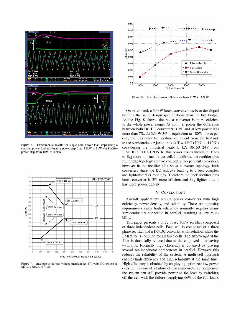
Figure 6. Experimental results for single cell, Power load steps using a constant power load (a)Negative power step from 3.3kW to lkW. (b) Positive power step from lkW to 3.3kW.
0) Ü CT!
F
• i 0.
.93
0)
V. J
(
sl I
330 V, 0.020 sec
(~303V, 0.015 sec J
c t7
^
>35V, 0.015 sec J "
/
I 280 V, 0.040 se = 1 I I
*
> \ f "1 IJ
MIL-SI D-/U4h
_JU
0 0.01 0.02 0.03 0.04 0.05 0.06 0.07 0.08 0.09 0.1
Time from Onset of Transient, Seconds
Figure 7. envelope of normal voltage transient for 270 volts DC system in Military Standard 704F,
0.99 | , , , , , 1
0.98- I •---- + ------ ----•—-•---•
0.97 -
0.96- *•**
&0.95- ***• ¿-.r.r :..~-.>B..._
- • -- •--o-
Filter + Rectifer
Full Bridge
Boost Converter
0.9 ' ' ' ' ' ' ' 1000 1500 2000 2500 3000
Output Power W
Figure 8. Rectifier system efficiencies from lkW to 3.3kW
On other hand, a 3.3kW boost converter has been developed keeping the same design specifications than the full bridge. As the Fig. 8 shows, the boost converter is more efficient in the whole power range. At nominal power the difference between both DC-DC converters is 3% and at low power it is more than 7%. At 3.3kW 3% is equivalent to 100W losses per cell; the maximum temperature increment from the heatsink to the semiconductor junction is A T = 42°C (70°C to 112°C) considering the industrial heatsink LA 10/150 24V from FISCHER ELEKTRONIK, this power losses increment leads to 1kg more in heatsink per cell. In addition, the rectifier plus full bridge topology are two completly independent converters, however in the rectifier plus boost converter topology, both converters share the DC inductor leading to a less complex and lighter/smaller topology. Therefore the buck rectifier plus boost converter is 3% more efficient and 3kg lighter thus it has more power density.
V. CONCLUSIONS
Aircraft applications require power converters with high efficiency, power density, and reliability. These are opposing requirements since high efficiency normally requires many semiconductors connected in parallel, resulting in low reliability.
This paper presents a three phase lOkW rectifier composed of three independent cells. Each cell is composed of a three phase rectifier and a DC-DC converter with isolation, while the EMI filter is common for all three cells. The size/weight of the filter is drastically reduced due to the employed interleaving technique. Normally high efficiency is obtained by placing several semiconductor components in parallel. However this reduces the reliability of the system. A multi-cell approach enables high efficiency and high reliability at the same time. High efficiency is obtained by employing optimized low power cells. In the case of a failure of one semiconductor component the system can still provide power to the load by switching off the cell with the failure (supplying 66% of the full load).
The isolation requirement facilitates a multi cell topology. A multi cell topology allows to deal with high efficiency, high power density and high reliability at the same time.
The implemented prototype has 91% of efficiency and 2.5% of THDj at full power. Step power responds of one cell confirm that the converter complies with aircraft transients requirements. The total weight of the rectifier system is approximately 10kg. The obtained power density and efficiency are heavily influenced by the military standard that has to be fulfilled.
A non-isolated boost converter has been presented in this work as well. This converter presents a much higher efficiency and much higher power density than the isolated one.
Although a multi cell topology provides important benefits in efficiency, power density and reliability. The negative issues of the isolated over the non-isolated topology, prevent the use of multi cell topologies when the isolation is not a requirement.
ACKNOWLEDGMENT
The authors would like to thank Military AIRBUS Spain for providing their laboratories for experimental testing and to Miguel Ángel Gil Palacios for his help in the development and design of the DC-DC boost converter.
REFERENCES
[1] J. A. Rosero, J. A. Ortega, E. Aldabas, and L. Romeral, "Moving towards a more electric aircraft," IEEE Aerospace and Electronic Systems Magazine, vol. 22, no. 3, pp. 3-9, 2007.
[2] J. S. Cloyd, "Status of the united states air force's more electric aircraft initiative," IEEE Aerospace and Electronic Systems Magazine, vol. 13, no. 4, pp. 17-22, 1998.
[3] W. G. Homeyer, E. E. Bowles, S. P. Lupan, P. S. Walia, and M. A. Maldonado, "Advanced power converters for more electric aircraft applications," in Proc. 32nd Intersociety Energy Conversion Engineering Conf. IECEC-97, vol. 1, 1997, pp. 591-596.
[4] D. Izquierdo, R. Azcona, F. del Cerro, C. Fernandez, and B. Delicado, "Electrical power distribution system (hv270dc), for application in more electric aircraft," in Proc. Twenty-Fifth Annual IEEE Applied Power Electronics Conf. and Exposition (APEC), 2010, pp. 1300-1305.
[5] R. I. Jones, "The more electric aircraft: the past and the future?" in Proc. IEE Colloquium Electrical Machines and Systems for the More Electric Aircraft (Ref No. 1999/180), 1999.
[6] K. Emadi and M. Ehsani, "Aircraft power systems: technology, state of the art, and future trends," IEEE Aerospace and Electronic Systems Magazine, vol. 15, no. 1, pp. 28-32, 2000.
[7] T. F. J. W. Kolar, "The essence of three-phase pfc rectifier systems," in Proceedings of the 33rd IEEE International Telecommunications Energy Conference (INTELEC 2011), Amsterdam, Netherlands, October 9-13 2011.
[8] B. Singh, B. N. Singh, A. Chandra, K. Al-Haddad, A. Pandey, and D. P. Kothari, "A review of three-phase improved power quality ac-dc converters," Industrial Electronics, IEEE Transactions on, vol. 51, no. 3, pp. 641-660, 2004.
[9] T. Nussbaumer and J. W. Kolar, "Comparison of 3-phase wide output voltage range pwm rectifiers," Industrial Electronics, IEEE Transactions on, vol. 54, no. 6, pp. 3422-3425, 2007.
[10] M. Nussbaumer, T. Kazuaki and J. W. Kolar, "Design and comparative evaluation of three-phase buck+boost and boost+buck unity power factor pwm rectifier systems for supplying variable dc voltage link converters," in 25th International Conference on Power Electronics (PCIM),, 2004.
[11] A. Stupar, T. Friedli, J. Miniboeck, and J. Kolar, "Towards a 99three-phase buck-type pfc rectifier for 400 v dcdistribution systems," Power Electronics, IEEE Transactions on, vol. PP, no. 99, p. 1, 2011.
[12] J. Kolar, F. Krismer, Y. Lobsiger, J. Muhlethaler, T. Nussbaumer, and J. Minibock, "Extreme efficiency power electronics," in Integrated Power Electronics Systems (CIPS), 2012 7th International Conference on, march 2012, pp. 1 -22.
[13] M. Baumann, U. Drofenik, and J. W. Kolar, "New wide input voltage range three-phase unity power factor rectifier formed by integration of a three-switch buck-derived front-end and a dc/dc boost converter output stage," in Proc. INTELEC Telecommunications Energy Conf. Twenty-second Int, 2000, pp. 461-470.
[14] M. Silva, N. Hensgens, J. Oliver, P. Alou, O. Garcia, and J. Cobos, "New considerations in the input filter design of a three-phase buck-type pwm rectifier for aircraft applications," in Energy Conversion Congress and Exposition (ECCE), 2011 IEEE, sept. 2011, pp. 4087 -4092.
[15] T. Nussbaumer, G. Gong, M. Heldwein, and J. Kolar, "Modeling and robust control of a three-phase buck+boost pwm rectifier (vrx-4)," Industry Applications, IEEE Transactions on, vol. 44, no. 2, pp. 650 -662, march-april 2008.
[16] M. Baumann, T. Nussbaumer, and J. W. Kolar, "Comparative evaluation of modulation methods of a three-phase buck + boost pwm rectifier, part i: Theoretical analysis," IET Power Electronics, no. 2, pp. 255-267, 2008.
[17] T. Nussbaumer, M. Baumann, and J. W. Kolar, "Comparative evaluation of modulation methods of a three-phase buck + boost pwm rectifier, part ii: Experimental verification," IET Power Electronics, no. 2, pp. 268-274, 2008.
[18] J. Sabate, V. Vlatkovic, R. Ridley, F. Lee, and B. Cho, "Design considerations for high-voltage high-power full-bridge zero-voltage-switched pwm converter," in Applied Power Electronics Conference and Exposition, 1990. APEC '90, Conference Proceedings 1990., Fifth Annual, march 1990, pp. 275 -284.
[19] R. Redi, N. Sokal, and L. Balogh, "A novel soft-switching full-bridge dc/dc converter: analysis, design considerations, and experimental results at 1.5 kw, 100 khz," Power Electronics, IEEE Transactions on, vol. 6, no. 3, pp. 408 -418, jul 1991.
[20] G. Hua and F. Lee, "Soft-switching techniques in pwm converters," Industrial Electronics, IEEE Transactions on, vol. 42, no. 6, pp. 595 -603, dec 1995.
[21] J. Cho, J. Sabate, and F. Lee, "Novel full bridge zero-voltage-transition pwm dc/dc converter for high power applications," in Applied Power Electronics Conference and Exposition, 1994. APEC '94. Conference Proceedings 1994., Ninth Annual, feb 1994, pp. 143 -149 vol.1.
[22] ANSYS and UPM, ANSYS PExprt 7.0, 2010. [23] M. Heldwein and J. Kolar, "Impact of emc filters on the power
density of modern three-phase pwm converters," Power Electronics, IEEE Transactions on, vol. 24, no. 6, pp. 1577 -1588, june 2009.
[24] N. Hensgens, M. Silva, J. Oliver, P. Alou, O. Garcia, and J. Cobos, "Analysis and optimized design of a distributed multi-stage emc filter for an interleaved three-phase pwm-rectifier system for aircraft applications," in Applied Power Electronics Conference and Exposition (APEC), 2012 Twenty-Seventh Annual IEEE, feb. 2012, pp. 465 -470.
[25] MIL-STD-704F, Departament of defense interface standard Aircraft Electric Power Characteristics Std., May 1991.