Embed Size (px)
Citation preview

AKERMAN HALL HANGAR BWBR Project No. 3.2009126.00FIRE LIFE SAFETY RENOVATIONS Sebesta Blomberg Project No. 206618.00
TABLE OF CONTENTS (U of M Project No’s. 1-266-09-1477) 00 0110 - 1(Design Development)
SECTION 00 01 10
TABLE OF CONTENTS
DIVISION 00 – PROCUREMENT AND CONTRACTING REQUIREMENTS
00 01 10 Table of Contents
DIVISION 22 – PLUMBING
22 05 00 Plumbing Materials & Methods22 05 17 Sleeves and Sleeve Seals for Plumbing Piping22 05 19 Plumbing Meters & Gauges22 05 23 Plumbing Valves22 05 29 Plumbing Hangers & Supports22 05 53 Plumbing Identification22 07 19 Plumbing Piping Insulation22 11 16 Domestic Water Piping22 13 16 Sanitary Waste & Vent Piping22 14 13 Storm Drainage Piping22 30 00 Plumbing Specialties22 40 00 Plumbing Fixtures
DIVISION 23 – HEATING, VENTILATING, AND AIR-CONDITIONING (HVAC)
23 05 00 HVAC Materials & Methods23 05 13 HVAC Motors23 05 17 HVAC Sleeves & Sleeve Seals23 05 19 HVAC Meters & Gages23 05 23 HVAC General Duty Valves23 05 29 HVAC Hangers & Supports23 05 48 HVAC Vibration And Seismic Controls23 05 53 HVAC Identification23 05 93 Testing, Adjusting, & Balancing23 07 13 Duct Insulation23 07 16 HVAC Equipment Insulation23 07 19 HVAC Pipe Insulation23 09 00 Instrumentation & Control For HVAC23 21 13 Hydronic Piping23 21 23 Hydronic Pumps23 22 13 Steam & Condensate Piping23 25 00 HVAC Water Treatment23 31 13 Metal Ductwork23 33 00 Ductwork Accessories23 34 16 Centrifugal Fans23 36 00 Air Terminal Units

AKERMAN HALL HANGAR BWBR Project No. 3.2009126.00FIRE LIFE SAFETY RENOVATIONS Sebesta Blomberg Project No. 206618.00
TABLE OF CONTENTS (U of M Project No’s. 1-266-09-1477) 00 0110 - 2(Design Development)
23 37 13 Diffusers, Registers and Grilles23 37 23 HVAC Gravity Ventilators23 41 00 Particulate Air Filtration23 57 00 Heat Exchangers for HVAC23 73 14 Factory Custom Air Handling Units23 82 39 Unit Heaters
DIVISION 26 - ELECTRICAL
26 05 00 Common Work Results for Electrical26 00 19 Low-Voltage Electrical Power Conductors and Cables26 05 26 Grounding and Bonding for Electrical Systems26 05 29 Hangers and Supports for Electrical Systems26 05 33 Raceway and Boxes for Electrical Systems26 05 36 Cable Trays for Electrical Systems26 05 53 Identification for Electrical Systems26 09 23 Lighting Control Devices26 22 00 Low-Voltage Transformers26 24 16 Panelboards26 27 26 Wiring Devices26 51 00 Interior Lighting
DIVISION 27 – COMMUNICATION
NOT USED
DIVISION 28 – ELECTRONIC SAFETY AND SECURITY
28 31 11 Digital, Addressable Fire Alarm System
END OF DOCUMENT

AKERMAN HALL HANGAR BWBR Project No. 3.2009126.00FIRE LIFE SAFETY RENOVATIONS Sebesta Blomberg Project No. 206618.00
PLUMBING MATERIALS & (U of M Project No’s. 1-266-09-1477) 22 05 00 - 1METHODS (Design Development)
SECTION 22 0500
PLUMBING MATERIALS AND METHODS
PART 1 - GENERAL
1.1 RELATED DOCUMENTS
A. Drawings and general provisions of the Contract, including General and SupplementaryConditions and Division 1 Specification Sections, apply to this Section.
1.2 SUMMARY
A. This Section includes the following:
1. Building service outages.
2. Electrical requirements for plumbing equipment.
3. Welding requirements.
4. Fire safety precautions
5. Plumbing systems commissioning
6. Piping materials and installation instructions common to most piping systems.
7. Transition fittings.
8. Dielectric fittings.
9. Escutcheons.
10. Grout.
11. Cutting and Patching
12. Plumbing Demolition
13. Equipment installation requirements common to equipment sections.
14. Painting and finishing.
15. Concrete bases.
16. Supports and anchorages.
1.3 DEFINITIONS
A. Finished Spaces: Spaces other than mechanical and electrical equipment rooms, furredspaces, pipe and duct shafts, unheated spaces immediately below roof, spaces aboveceilings, unexcavated spaces, crawlspaces, and tunnels.
B. Exposed, Interior Installations: Exposed to view indoors. Examples include finishedoccupied spaces and mechanical equipment rooms.
C. Exposed, Exterior Installations: Exposed to view outdoors or subject to outdoor ambienttemperatures and weather conditions. Examples include rooftop locations.

AKERMAN HALL HANGAR BWBR Project No. 3.2009126.00FIRE LIFE SAFETY RENOVATIONS Sebesta Blomberg Project No. 206618.00
PLUMBING MATERIALS & (U of M Project No’s. 1-266-09-1477) 22 05 00 - 2METHODS (Design Development)
D. Concealed, Interior Installations: Concealed from view and protected from physicalcontact by building occupants. Examples include above ceilings and in duct shafts.
E. Concealed, Exterior Installations: Concealed from view and protected from weatherconditions and physical contact by building occupants but subject to outdoor ambienttemperatures. Examples include installations within unheated shelters.
F. The following are industry abbreviations for plastic materials:
1. ABS: Acrylonitrile-butadiene-styrene plastic.
2. CPVC: Chlorinated polyvinyl chloride plastic.
3. PE: Polyethylene plastic.
4. PVC: Polyvinyl chloride plastic.
G. The following are industry abbreviations for rubber materials:
1. EPDM: Ethylene-propylene-diene terpolymer rubber.
2. NBR: Acrylonitrile-butadiene rubber.
1.4 SUBMITTALS
A. Product Data: For the following:
1. Transition fittings.
2. Dielectric fittings.
3. Mechanical sleeve seals.
4. Escutcheons.
B. Welding certificates.
1.5 QUALITY ASSURANCE
A. Product Standards:
1. Refer to Division 1.
2. Where products are specified by manufacturer, brand name or catalog number,this establishes the standard of quality and style of the product to be providedunder the Contract, unless a change in quality or style is approved by Owner.
3. All Contractor-furnished equipment, including its component parts, shall be thecurrent standard products of the manufacturer in order to insure prompt andcontinuing service and replacement of parts.
4. Where 2 or more units of the same class of equipment are required, these unitsshall be the products of a single manufacturer; however, the component parts ofthe equipment need not be the product of the same manufacturer.
B. Referenced Standards:
1. The following are names of technical and trade organizations, together with thecorresponding acronyms, used in this Specification when citing specificstandards published by these organizations:

AKERMAN HALL HANGAR BWBR Project No. 3.2009126.00FIRE LIFE SAFETY RENOVATIONS Sebesta Blomberg Project No. 206618.00
PLUMBING MATERIALS & (U of M Project No’s. 1-266-09-1477) 22 05 00 - 3METHODS (Design Development)
a. Air-Conditioning and Refrigeration Institute (ARI)
b. American Concrete Institute
c. American Conference of Governmental Industrial Hygienists
d. American Gas Association (AGA)
e. American Institute of Steel Construction
f. American National Standards Institute (ANSI)
g. American Society of Heating, Refrigeration and Air ConditioningEngineers
h. American Society of Mechanical Engineers (ASME)
i. American Society for Testing Materials (ASTM)
j. American Water Works Association (AWWA)
k. American Welding Society
l. ANSI Code for Power Piping B31.1
m. Hydraulic Institute Standards for Centrifugal, Rotary and ReciprocatingPumps
n. Institute of Electrical and Electronic Engineers
o. National Bureau of Standards
p. National Commercial and Industrial Insulation Standards
q. National Electrical Manufacturers Association (NEMA)
r. National Electric Code (NEC)
s. National Safety Code for Mechanical Refrigeration
t. Occupational Safety and Health Organization (OSHA)
u. Tubular Exchanger Manufacturers Association (TEMA)
v. Underwriters Laboratories (UL)
2. Where a reference standard is cited in this Specification, the subject to which itapplies (equipment, material or work) shall be in compliance with the mostrecent edition of that standard.
3. None of the above, however, shall be construed as relieving Contractor fromcomplying with any requirement in this Specification that may be in excess of,but not contrary to, the referenced standard.
1.6 BUILDING SERVICE OUTAGES
A. Service Outage Request: The contractor shall request all building service outages throughthe owner’s representative. The contractor shall provide a minimum notification of 24hours.
AKERMAN HALL HANGAR BWBR Project No. 3.2009126.00FIRE LIFE SAFETY RENOVATIONS Sebesta Blomberg Project No. 206618.00
PLUMBING MATERIALS & (U of M Project No’s. 1-266-09-1477) 22 05 00 - 4METHODS (Design Development)
1.7 ELECTRICAL REQUIREMENTS FOR PLUMBING EQUIPMENT
A. Equipment of higher electrical characteristics may be furnished provided such proposedequipment is approved in writing and connecting electrical services, circuit breakers, andconduit sizes are appropriately modified. If minimum energy ratings or efficiencies arespecified, equipment shall comply with requirements.
1.8 WELDING REQUIREMENTS
A. Steel Support Welding: Qualify processes and operators according to AWS D1.1,"Structural Welding Code--Steel."
1.9 FIRE SAFETY PRECAUTIONS
A. A Hot Works Permit is required for any temporary operation that involves open flames orproduces heat and/or sparks. Such operations include, but are not limited to, brazingcutting, grinding, soldering, thawing pipe, torch applied roofing, and welding. Beforedoing any type of open flame or hot works operation, obtain a Hot Works Permit fromthe customer service representative in the particular zone where the work will beperformed.
B. All grinding, cutting, brazing, sweating, or welding operations carried on in the vicinityof, or accessible to combustible material, shall be adequately protected to make certainthat a spark or hot slag does not reach the combustible material and start a fire.
C. When it is necessary to do grinding, cutting, brazing, sweating or welding close to woodconstruction in pipe shafts or other locations where combustible materials cannot beremoved or adequately protected, employ fireproof blankets and proper fireextinguishers. A helper shall be stationed nearby to guard against sparks and fire.
D. Whenever combustible material has been exposed to molten metal or hot slag fromwelding or cutting operations or spatter from electric arc, a fireguard shall be kept at theplace of the hot work for at least one hour after completion to make sure that smolderingfires to not start.
E. When welding or cutting in vertical pipe shaft or floor opening, a fireguard shall examineall floors below the welding or cutting operation. The fireguard shall be kept on duty forat least one hour after completion of work to guard against fires.
1.10 DELIVERY, STORAGE, AND HANDLING
A. Deliver pipes and tubes with factory-applied end caps. Maintain end caps throughshipping, storage, and handling to prevent pipe end damage and to prevent entrance ofdirt, debris, and moisture.
B. Store plastic pipes protected from direct sunlight. Support to prevent sagging andbending.
1.11 COORDINATION
A. Arrange for pipe spaces, chases, slots, and openings in building structure during progressof construction, to allow for plumbing installations.

AKERMAN HALL HANGAR BWBR Project No. 3.2009126.00FIRE LIFE SAFETY RENOVATIONS Sebesta Blomberg Project No. 206618.00
PLUMBING MATERIALS & (U of M Project No’s. 1-266-09-1477) 22 05 00 - 5METHODS (Design Development)
B. Coordinate installation of required supporting devices and set sleeves in poured-in-placeconcrete and other structural components as they are constructed.
C. Coordinate requirements for access panels and doors for mechanical items requiringaccess that are concealed behind finished surfaces. Access panels and doors are specifiedin Division 8 Section "Access Doors and Frames."
1.12 STARTUP/COMMISSIONING
A. The building plumbing systems shall be commissioned in accordance with the latestedition of the ASHRAE document, “Guideline for Commissioning of PlumbingSystems”. Documentation and testing of these systems is required in cooperation withthe Commissioning Authority. Project closeout is dependant on successful completion ofall commissioning procedures, documentation, and issue closure. Refer to ProjectCloseout, Section 01700, for substantial completion details. Refer to Section 01810 fordetailed commissioning requirements.
B. For purposes of implementing this guideline, the Commissioning Authority shall bedefined as being a member of the University Staff.
C. The contractor shall provide labor, material, and equipment required to facilitate thecommissioning process as well as making adjustments and modifications needed tocorrect deficiencies in the operation of the equipment.
D. The contractor shall submit copies of the service tickets to the commissioning authorityduring the one-year correction period. This step verifies that there are no unresolveddeficiencies with the system.
PART 2 - PRODUCTS
2.1 MANUFACTURERS
A. In other Part 2 articles where subparagraph titles below introduce lists, the followingrequirements apply for product selection:
1. Manufacturers: Subject to compliance with requirements, provide products bythe manufacturers specified.
2.2 PIPE, TUBE, AND FITTINGS
A. Refer to individual Division 22 piping Sections for pipe, tube, and fitting materials andjoining methods.
B. Pipe Threads: ASME B1.20.1 for factory-threaded pipe and pipe fittings.
2.3 JOINING MATERIALS
A. Refer to individual Division 22 piping Sections for special joining materials not listedbelow.
B. Pipe-Flange Gasket Materials: Suitable for chemical and thermal conditions of pipingsystem contents.

AKERMAN HALL HANGAR BWBR Project No. 3.2009126.00FIRE LIFE SAFETY RENOVATIONS Sebesta Blomberg Project No. 206618.00
PLUMBING MATERIALS & (U of M Project No’s. 1-266-09-1477) 22 05 00 - 6METHODS (Design Development)
1. ASME B16.21, nonmetallic, flat, asbestos-free, 1/8-inch maximum thicknessunless thickness or specific material is indicated.
a. Full-Face Type: For flat-face, Class 125, cast-iron and cast-bronzeflanges.
b. Narrow-Face Type: For raised-face, Class 250, cast-iron and steelflanges.
2. AWWA C110, rubber, flat face, 1/8 inch thick, unless otherwise indicated; andfull-face or ring type, unless otherwise indicated.
C. Flange Bolts and Nuts: ASME B18.2.1, carbon steel, unless otherwise indicated.
D. Plastic, Pipe-Flange Gasket, Bolts, and Nuts: Type and material recommended by pipingsystem manufacturer, unless otherwise indicated.
E. Solder Filler Metals: ASTM B 32, lead-free alloys. Include water-flushable fluxaccording to ASTM B 813.
F. Brazing Filler Metals: AWS A5.8, BCuP Series, copper-phosphorus alloys for general-duty brazing, unless otherwise indicated; and AWS A5.8, BAg1, silver alloy forrefrigerant piping, unless otherwise indicated.
G. Welding Filler Metals: Comply with AWS D10.12 for welding materials appropriate forwall thickness and chemical analysis of steel pipe being welded.
H. Solvent Cements for Joining Plastic Piping:
1. ABS Piping: ASTM D 2235.
2. CPVC Piping: ASTM F 493.
3. PVC Piping: ASTM D 2564. Include primer according to ASTM F 656.
4. PVC to ABS Piping Transition: ASTM D 3138.
2.4 TRANSITION FITTINGS
A. AWWA Transition Couplings: Same size as, and with pressure rating at least equal toand with ends compatible with, piping to be joined.
1. Manufacturers:
a. Cascade Waterworks Mfg. Co.
b. Dresser Industries, Inc.; DMD Div.
c. Ford Meter Box Company, Incorporated (The); Pipe Products Div.
d. JCM Industries.
e. Smith-Blair, Inc.
f. Viking Johnson.
2. Underground Piping NPS 1-1/2 and Smaller: Manufactured fitting or coupling.
3. Underground Piping NPS 2 and Larger: AWWA C219, metal sleeve-typecoupling.

AKERMAN HALL HANGAR BWBR Project No. 3.2009126.00FIRE LIFE SAFETY RENOVATIONS Sebesta Blomberg Project No. 206618.00
PLUMBING MATERIALS & (U of M Project No’s. 1-266-09-1477) 22 05 00 - 7METHODS (Design Development)
4. Aboveground Pressure Piping: Pipe fitting.
B. Plastic-to-Metal Transition Fittings: CPVC and PVC one-piece fitting withmanufacturer's Schedule 80 equivalent dimensions; one end with threaded brass insert,and one solvent-cement-joint end.
1. Manufacturers:
a. Eslon Thermoplastics.
C. Plastic-to-Metal Transition Adaptors: One-piece fitting with manufacturer's SDR 11equivalent dimensions; one end with threaded brass insert, and one solvent-cement-jointend.
1. Manufacturers:
a. Thompson Plastics, Inc.
D. Plastic-to-Metal Transition Unions: MSS SP-107, CPVC and PVC four-part union.Include brass end, solvent-cement-joint end, rubber O-ring, and union nut.
1. Manufacturers:
a. NIBCO INC.
b. NIBCO, Inc.; Chemtrol Div.
E. Flexible Transition Couplings for Underground Nonpressure Drainage Piping:ASTM C 1173 with elastomeric sleeve, ends same size as piping to be joined, andcorrosion-resistant metal band on each end.
1. Manufacturers:
a. Cascade Waterworks Mfg. Co.
b. Fernco, Inc.
c. Mission Rubber Company.
d. Plastic Oddities, Inc.
2.5 DIELECTRIC FITTINGS
A. Description: Combination fitting of copper alloy and ferrous materials with threaded,solder-joint, plain, or weld-neck end connections that match piping system materials.
B. Insulating Material: Suitable for system fluid, pressure, and temperature.
C. Dielectric Unions: Factory-fabricated, union assembly, for 250-psig minimum workingpressure at 180 deg F.
1. Manufacturers:
a. Capitol Manufacturing Co.
b. Central Plastics Company.
c. Eclipse, Inc.
d. Epco Sales, Inc.

AKERMAN HALL HANGAR BWBR Project No. 3.2009126.00FIRE LIFE SAFETY RENOVATIONS Sebesta Blomberg Project No. 206618.00
PLUMBING MATERIALS & (U of M Project No’s. 1-266-09-1477) 22 05 00 - 8METHODS (Design Development)
e. Hart Industries, International, Inc.
f. Watts Industries, Inc.; Water Products Div.
g. Zurn Industries, Inc.; Wilkins Div.
D. Dielectric Flanges: Factory-fabricated, companion-flange assembly, for 150- or 300-psigminimum working pressure as required to suit system pressures.
1. Manufacturers:
a. Capitol Manufacturing Co.
b. Central Plastics Company.
c. Epco Sales, Inc.
d. Watts Industries, Inc.; Water Products Div.
E. Dielectric-Flange Kits: Companion-flange assembly for field assembly. Include flanges,full-face- or ring-type neoprene or phenolic gasket, phenolic or polyethylene bolt sleeves,phenolic washers, and steel backing washers.
1. Manufacturers:
a. Advance Products & Systems, Inc.
b. Calpico, Inc.
c. Central Plastics Company.
d. Pipeline Seal and Insulator, Inc.
2. Separate companion flanges and steel bolts and nuts shall have 150- or 300-psigminimum working pressure where required to suit system pressures.
F. Dielectric Couplings: Galvanized-steel coupling with inert and noncorrosive,thermoplastic lining; threaded ends; and 300-psig minimum working pressure at 225deg F.
1. Manufacturers:
a. Calpico, Inc.
b. Lochinvar Corp.
G. Dielectric Nipples: Electroplated steel nipple with inert and noncorrosive, thermoplasticlining; plain, threaded, or grooved ends; and 300-psig minimum working pressure at 225deg F.
1. Manufacturers:
a. Perfection Corp.
b. Precision Plumbing Products, Inc.
c. Sioux Chief Manufacturing Co., Inc.
d. Victaulic Co. of America.

AKERMAN HALL HANGAR BWBR Project No. 3.2009126.00FIRE LIFE SAFETY RENOVATIONS Sebesta Blomberg Project No. 206618.00
PLUMBING MATERIALS & (U of M Project No’s. 1-266-09-1477) 22 05 00 - 9METHODS (Design Development)
2.6 ESCUTCHEONS
A. Description: Manufactured wall and ceiling escutcheons and floor plates, with an ID toclosely fit around pipe, tube, and insulation of insulated piping and an OD thatcompletely covers opening.
B. One-Piece, Deep-Pattern Type: Deep-drawn, box-shaped brass with polished chrome-plated finish.
C. One-Piece, Cast-Brass Type: With set screw.
1. Finish: Polished chrome-plated and rough brass.
D. Split-Casting, Cast-Brass Type: With concealed hinge and set screw.
1. Finish: Polished chrome-plated and rough brass.
E. One-Piece, Stamped-Steel Type: With set screw or spring clips and chrome-plated finish.
F. Split-Plate, Stamped-Steel Type: With concealed hinge, set screw or spring clips, andchrome-plated finish.
G. One-Piece, Floor-Plate Type: Cast-iron floor plate.
H. Split-Casting, Floor-Plate Type: Cast brass with concealed hinge and set screw.
2.7 GROUT
A. Description: ASTM C 1107, Grade B, nonshrink and nonmetallic, dry hydraulic-cementgrout.
1. Characteristics: Post-hardening, volume-adjusting, nonstaining, noncorrosive,nongaseous, and recommended for interior and exterior applications.
2. Design Mix: 5000-psi, 28-day compressive strength.
3. Packaging: Premixed and factory packaged.
PART 3 - EXECUTION
3.1 PLUMBING DEMOLITION
A. Refer to Division 1 Section "Cutting and Patching" and Division 2 Section "SelectiveDemolition" for general demolition requirements and procedures.
B. Disconnect, demolish, and remove plumbing systems, equipment, and componentsindicated to be removed.
1. Piping to Be Removed: Remove portion of piping indicated to be removed andcap or plug remaining piping with same or compatible piping material.
2. Piping to Be Abandoned in Place: Drain piping and cap or plug piping withsame or compatible piping material.
3. Equipment to Be Removed: Disconnect and cap services and remove equipment.

AKERMAN HALL HANGAR BWBR Project No. 3.2009126.00FIRE LIFE SAFETY RENOVATIONS Sebesta Blomberg Project No. 206618.00
PLUMBING MATERIALS & (U of M Project No’s. 1-266-09-1477) 22 05 00 - 10METHODS (Design Development)
4. Equipment to Be Removed and Reinstalled: Disconnect and cap services andremove, clean, and store equipment; when appropriate, reinstall, reconnect, andmake equipment operational.
5. Equipment to Be Removed and Salvaged: Disconnect and cap services andremove equipment and deliver to Owner.
C. If pipe, insulation, or equipment to remain is damaged in appearance or is unserviceable,remove damaged or unserviceable portions and replace with new products of equalcapacity and quality.
3.2 CUTTING AND PATCHING
A. General: Comply with Division 1 Section “Execution” for general cutting and patchingprocedures.
B. Core drilling, cutting and patching, required for the installation of plumbing equipment asshown on the drawings and/or specified in Division 22 shall be the responsibility of thisContractor except where specifically stated otherwise. Only workers that areexperienced, skilled, and licensed for the particular type of work involved, shall performcutting and patching.
1. Hanger inserts and pipe sleeves to be incorporated into the general buildingconstruction shall be furnished and installed by Contractor in ample time to avoiddelaying the work of other trades or causing unnecessary cutting and patchingwork. Should any cutting be required to set inserts or sleeves, it shall beperformed by Contractor using proper skilled tradesmen for the materialinvolved, such as a bricklayer for masonry wall patching, etc.
2. Core drilling shall be used where practical. Reasonable care shall be exercisedduring cutting to keep patching at a minimum.
3. Under no circumstances shall any cutting or burning of the structural parts of thebuilding be undertaken without authority of Engineer.
4. When identical patching materials are not available for exteriors of historicbuildings, submit alternate materials for review with the University ArchitectsOffice.
3.3 PIPING SYSTEMS - COMMON REQUIREMENTS
A. Install piping according to the following requirements and Division 22 Sectionsspecifying piping systems.
B. Drawing plans, schematics, and diagrams indicate general location and arrangement ofpiping systems. Indicated locations and arrangements were used to size pipe andcalculate friction loss, expansion, pump sizing, and other design considerations. Installpiping as indicated unless deviations to layout are approved on Coordination Drawings.
C. Install piping in concealed locations, unless otherwise indicated and except in equipmentrooms and service areas.
D. Install piping indicated to be exposed and piping in equipment rooms and service areas atright angles or parallel to building walls. Diagonal runs are prohibited unless specificallyindicated otherwise.

AKERMAN HALL HANGAR BWBR Project No. 3.2009126.00FIRE LIFE SAFETY RENOVATIONS Sebesta Blomberg Project No. 206618.00
PLUMBING MATERIALS & (U of M Project No’s. 1-266-09-1477) 22 05 00 - 11METHODS (Design Development)
E. Install piping above accessible ceilings to allow sufficient space for ceiling panelremoval.
F. Install piping to permit valve servicing.
G. Install piping at indicated slopes.
H. Install piping free of sags and bends.
I. Install fittings for changes in direction and branch connections.
J. Install piping to allow application of insulation.
K. Select system components with pressure rating equal to or greater than system operatingpressure.
L. Install escutcheons for penetrations of walls, ceilings, and floors according to thefollowing:
1. New and existing piping to remain: Use the following
a. Piping with Fitting or Sleeve Protruding from Wall: One-piece, deep-pattern type.
b. Chrome-Plated Piping: One-piece, cast-brass type with polishedchrome-plated finish.
c. Insulated Piping: One-piece, stamped-steel type with spring clips.
d. Bare Piping at Wall and Floor Penetrations in Finished Spaces: One-piece, cast-brass type with polished chrome-plated finish.
e. Bare Piping at Ceiling Penetrations in Finished Spaces: One-piece orsplit-casting, cast-brass type with polished chrome-plated finish.
f. Bare Piping in Unfinished Service Spaces: One-piece, stamped-steeltype with concealed or exposed-rivet hinge and set screw.
g. Bare Piping in Equipment Rooms: One-piece, stamped-steel type withset screw.
h. Bare Piping at Floor Penetrations in Equipment Rooms: One-piece,floor-plate type. Install sleeves for pipes passing through concrete andmasonry walls, gypsum board partitions, and concrete floor and roofslabs.
M. Fire-Barrier Penetrations: Maintain indicated fire rating of walls, partitions, ceilings, andfloors at pipe penetrations. Seal pipe penetrations with firestop materials. Refer toDivision 7 Section "Firestopping" for materials.
N. Verify final equipment locations for roughing-in.
O. Refer to equipment specifications in other Sections of these Specifications for roughing-in requirements.

AKERMAN HALL HANGAR BWBR Project No. 3.2009126.00FIRE LIFE SAFETY RENOVATIONS Sebesta Blomberg Project No. 206618.00
PLUMBING MATERIALS & (U of M Project No’s. 1-266-09-1477) 22 05 00 - 12METHODS (Design Development)
3.4 PIPING JOINT CONSTRUCTION
A. Join pipe and fittings according to the following requirements and Division 22 Sectionsspecifying piping systems.
B. Ream ends of pipes and tubes and remove burrs. Bevel plain ends of steel pipe.
C. Remove scale, slag, dirt, and debris from inside and outside of pipe and fittings beforeassembly.
D. Soldered Joints: Apply ASTM B 813, water-flushable flux, unless otherwise indicated,to tube end. Construct joints according to ASTM B 828 or CDA's "Copper TubeHandbook," using lead-free solder alloy complying with ASTM B 32.
E. Brazed Joints: Construct joints according to AWS's "Brazing Handbook," "Pipe andTube" Chapter, using copper-phosphorus brazing filler metal complying with AWS A5.8.
F. Threaded Joints: Thread pipe with tapered pipe threads according to ASME B1.20.1.Cut threads full and clean using sharp dies. Ream threaded pipe ends to remove burrsand restore full ID. Join pipe fittings and valves as follows:
1. Apply appropriate tape or thread compound to external pipe threads unless dryseal threading is specified.
2. Damaged Threads: Do not use pipe or pipe fittings with threads that are corrodedor damaged. Do not use pipe sections that have cracked or open welds.
G. Flanged Joints: Select appropriate gasket material, size, type, and thickness for serviceapplication. Install gasket concentrically positioned. Use suitable lubricants on boltthreads.
H. Plastic Piping Solvent-Cement Joints: Clean and dry joining surfaces. Join pipe andfittings according to the following:
1. Comply with ASTM F 402 for safe-handling practice of cleaners, primers, andsolvent cements.
2. CPVC Piping: Join according to ASTM D 2846/D 2846M Appendix.
3. PVC Pressure Piping: Join schedule number ASTM D 1785, PVC pipe and PVCsocket fittings according to ASTM D 2672. Join other-than-schedule-numberPVC pipe and socket fittings according to ASTM D 2855.
4. PVC Nonpressure Piping: Join according to ASTM D 2855.
I. Plastic Pressure Piping Gasketed Joints: Join according to ASTM D 3139.
J. Plastic Nonpressure Piping Gasketed Joints: Join according to ASTM D 3212.
3.5 PIPING CONNECTIONS
A. Make connections according to the following, unless otherwise indicated:
1. Install unions, in piping NPS 2 and smaller, adjacent to each valve and at finalconnection to each piece of equipment.

AKERMAN HALL HANGAR BWBR Project No. 3.2009126.00FIRE LIFE SAFETY RENOVATIONS Sebesta Blomberg Project No. 206618.00
PLUMBING MATERIALS & (U of M Project No’s. 1-266-09-1477) 22 05 00 - 13METHODS (Design Development)
2. Install flanges, in piping NPS 2-1/2 and larger, adjacent to flanged valves and atfinal connection to each piece of equipment.
3. Dry Piping Systems: Install dielectric unions and flanges to connect pipingmaterials of dissimilar metals.
4. Wet Piping Systems: Install dielectric coupling and nipple fittings to connectpiping materials of dissimilar metals.
3.6 EQUIPMENT INSTALLATION - COMMON REQUIREMENTS
A. Install equipment to allow maximum possible headroom unless specific mounting heightsare not indicated.
B. Install equipment level and plumb, parallel and perpendicular to other building systemsand components in exposed interior spaces, unless otherwise indicated.
C. Install plumbing equipment to facilitate service, maintenance, and repair or replacementof components. Connect equipment for ease of disconnecting, with minimuminterference to other installations. Extend grease fittings to accessible locations.
D. Install equipment to allow right of way for piping installed at required slope.
3.7 PAINTING
A. Piping and other equipment that is furnished and installed under Division 22 and isexposed in finished spaces will be completed under Division 9 of the Specifications.
B. Painting of exposed piping, ducts and other equipment in equipment spaces andaccessible tunnels, crawl spaces, shafts, and other unfinished spaces, including paintingof canvas jacketed pipe insulation, shall be completed by this Contractor.
C. Damage and Touchup: Repair marred and damaged factory-painted finishes withmaterials and procedures to match original factory finish.
3.8 CONCRETE BASES
A. The concrete work, including formwork and setting of anchor bolts and sleeves, isspecified in other sections. Contractor shall be responsible for providing an accuratedrawing of each equipment base required with the location of each anchor bolt properlydimensioned, and before the concrete is placed, the Contractor shall check and approvethe formwork and placement of the anchor bolts.
B. Contractor shall furnish anchor bolt and sleeve assemblies for all concrete equipmentbases required in connection with the work under this Contract. Anchor bolts and sleevesshall be of approved material, size and shape. Inside diameter of sleeves shall be at least2-1/2 times the bolt diameter.
C. After Contractor has set and leveled the equipment, he shall be responsible for furnishingand proper placing of non-shrink grout for each base with 1 inch nominal thicknessbetween the top of the concrete base and the bottom of the equipment base. Leveling ofequipment and grouting shall be in strict accordance with manufacturer’srecommendations and instructions of Owner’s Construction Representative.

AKERMAN HALL HANGAR BWBR Project No. 3.2009126.00FIRE LIFE SAFETY RENOVATIONS Sebesta Blomberg Project No. 206618.00
PLUMBING MATERIALS & (U of M Project No’s. 1-266-09-1477) 22 05 00 - 14METHODS (Design Development)
3.9 ERECTION OF METAL SUPPORTS AND ANCHORAGES
A. Refer to Division 5 Section "Metal Fabrications" for structural steel.
B. Cut, fit, and place miscellaneous metal supports accurately in location, alignment, andelevation to support and anchor mechanical materials and equipment.
C. Field Welding: Comply with AWS D1.1.
3.10 GROUTING
A. Mix and install grout for mechanical equipment base bearing surfaces, pump and otherequipment base plates, and anchors.
B. Clean surfaces that will come into contact with grout.
C. Provide forms as required for placement of grout.
D. Avoid air entrapment during placement of grout.
E. Place grout, completely filling equipment bases.
F. Place grout on concrete bases and provide smooth bearing surface for equipment.
G. Place grout around anchors.
H. Cure placed grout.
END OF SECTION 22 0500

AKERMAN HALL HANGAR BWBR Project No. 3.2009126.00FIRE LIFE SAFETY RENOVATIONS Sebesta Blomberg Project No. 206618.00
SLEEVES AND SLEEVE SEALS (U of M Project No’s. 1-266-09-1477) 22 0517 - 1FOR PLUMBING PIPING (Design Development)
SECTION 22 05 17
SLEEVES AND SLEEVE SEALS FOR PLUMBING PIPING
PART 1 - GENERAL
1.1 RELATED DOCUMENTS
A. Drawings and general provisions of the Contract, including General and SupplementaryConditions and Division 01 Specification Sections, apply to this Section.
1.2 SUMMARY
A. Section Includes:
1. Sleeves.
2. Sleeve-seal systems.
1.3 SUBMITTALS
A. Product Data: For each type of product indicated.
PART 2 - PRODUCTS
2.1 SLEEVES
A. Galvanized-Steel Wall Pipes: ASTM A 53/A 53M, Schedule 40, with plain ends andwelded steel collar; zinc coated.
2.2 SLEEVE-SEAL SYSTEMS
A. Manufacturers: Subject to compliance with requirements, provide products by one of thefollowing:
1. Advance Products & Systems, Inc.
2. CALPICO, Inc.
3. Metraflex Company (The).
4. Pipeline Seal and Insulator, Inc. (Link-seal)
5. Proco Products, Inc.
B. Description: Modular sealing-element unit, designed for field assembly, for fillingannular space between piping and sleeve.
1. Sealing Elements: EPDM-rubber interlocking links shaped to fit surface of pipe.Include type and number required for pipe material and size of pipe.
2. Pressure Plates: Plastic.
3. Connecting Bolts and Nuts: Carbon steel, with corrosion-resistant coating, oflength required to secure pressure plates to sealing elements.

AKERMAN HALL HANGAR BWBR Project No. 3.2009126.00FIRE LIFE SAFETY RENOVATIONS Sebesta Blomberg Project No. 206618.00
SLEEVES AND SLEEVE SEALS (U of M Project No’s. 1-266-09-1477) 22 0517 - 2FOR PLUMBING PIPING (Design Development)
PART 3 - EXECUTION
3.1 SLEEVE INSTALLATION
A. Install sleeves for piping passing through penetrations in floors, partitions, roofs, andwalls.
B. For sleeves that will have sleeve-seal system installed, select sleeves of size large enoughto provide annular clear space between piping and concrete slabs and walls as required bysleeve-seal system.
1. Sleeves are not required for core-drilled holes.
C. Install sleeves in concrete floors, concrete roof slabs, and concrete walls as new slabs andwalls are constructed.
1. Permanent sleeves are not required for holes in slabs formed by molded-PE or -PP sleeves.
2. Cut sleeves to length for mounting flush with both surfaces.
a. Exception: Extend sleeves installed in floors of mechanical equipmentareas or other wet areas 2 inches above finished floor level.
3. Using grout, seal the space outside of sleeves in slabs and walls without sleeve-seal system.
D. Install sleeves for pipes passing through interior partitions.
1. Cut sleeves to length for mounting flush with both surfaces.
2. Install sleeves that are large enough to provide 1/4-inch annular clear spacebetween sleeve and pipe or pipe insulation.
3. Seal annular space between sleeve and piping or piping insulation; use jointsealants appropriate for size, depth, and location of joint. Comply withrequirements for sealants specified in Division 07 Section "Joint Sealants."
E. Fire-Barrier Penetrations: Maintain indicated fire rating of walls, partitions, ceilings, andfloors at pipe penetrations. Seal pipe penetrations with firestop materials. Comply withrequirements for firestopping specified in Division 07 Section "Penetration Firestopping."
3.2 SLEEVE-SEAL-SYSTEM INSTALLATION
A. Install sleeve-seal systems in sleeves in exterior concrete walls and slabs-on-grade atservice piping entries into building.
B. Select type, size, and number of sealing elements required for piping material and sizeand for sleeve ID or hole size. Position piping in center of sleeve. Center piping inpenetration, assemble sleeve-seal system components, and install in annular spacebetween piping and sleeve. Tighten bolts against pressure plates that cause sealingelements to expand and make a watertight seal.
END OF SECTION 22 0517

AKERMAN HALL HANGAR BWBR Project No. 3.2009126.00FIRE LIFE SAFETY RENOVATIONS Sebesta Blomberg Project No. 206618.00
PLUMBING METERS AND (U of M Project No’s. 1-266-09-1477) 22 05 19 - 1GAGES (Design Development)
SECTION 22 05 19
PLUMBING METERS AND GAGES
PART 1 - GENERAL
1.1 SUMMARY
A. This Section includes flow meters and gages for plumbing systems.
1.2 SUBMITTALS
A. Product Data: Include scale ranges, ratings, and calibrated performance curves for eachmeter, gage, fitting, specialty, and accessory specified. Include interconnecting wiringdiagrams.
B. Shop Drawings: Include schedule indicating manufacturer's number, scale range, fittings,and location for each meter and gage.
C. Product Certificates: Signed by manufacturers of meters and gages certifying accuraciesunder specified operating conditions and compliance with specified requirements.
PART 2 - PRODUCTS
2.1 MANUFACTURERS
A. Available Manufacturers: Subject to compliance with requirements, provide products bythe manufacturers specified:
1. Liquid-in-Glass Thermometers:
a. Dresser Industries, Inc.; Instrument Div.; Weksler Instruments OperatingUnit.
b. Ernst Gage Co.
c. Marsh Bellofram.
d. Palmer Instruments, Inc.
e. Trerice: H. O. Trerice Co.
f. Weiss Instruments, Inc.
g. Winter's Thermogauges, Inc.
2. Pressure Gages:
a. AMETEK, Inc.; U.S. Gauge Div.
b. Dresser Industries, Inc.; Instrument Div.; Ashcroft Commercial SalesOperation.
c. Dresser Industries, Inc.; Instrument Div.; Weksler Instruments OperatingUnit.
d. Trerice: H. O. Trerice Co.
e. Weiss Instruments, Inc.

AKERMAN HALL HANGAR BWBR Project No. 3.2009126.00FIRE LIFE SAFETY RENOVATIONS Sebesta Blomberg Project No. 206618.00
PLUMBING METERS AND (U of M Project No’s. 1-266-09-1477) 22 05 19 - 2GAGES (Design Development)
f. WIKA Instruments Corp.
3. Test Plugs:
a. Peterson Equipment Co., Inc.
2.2 THERMOMETERS, GENERAL
A. Scale Range: Temperature ranges for services listed are as follows:
1. Domestic Water: 0 to 100 deg F, with 2-degree scale divisions.
2. Domestic water: 0 to 200 deg F
3. Accuracy: Plus or minus 1 percent of range span or plus or minus one scale divi-sion to maximum of 1.5 percent of range span.
2.3 LIQUID-IN-GLASS THERMOMETERS
A. Description: ASTM E 1.
B. Case: Die cast and aluminum finished in baked-epoxy enamel, glass front, spring se-cured, 9 inches long.
C. Adjustable Joint: Finish to match case, 180-degree adjustment in vertical plane, 360-degree adjustment in horizontal plane, with locking device.
D. Tube: Red or blue reading, organic-liquid filled with magnifying lens.
E. Scale: Satin-faced nonreflective aluminum with permanently etched markings.
F. Stem: Copper-plated steel, aluminum, or brass for separable socket; of length to suit in-stallation.
2.4 THERMOMETER WELLS
A. Description: Fitting with protective well for installation in threaded pipe fitting to holdthermometer.
1. Material: Stainless steel, for use in steel piping.
2. Extension-Neck Length: Nominal thickness of 2 inches, but not less than thick-ness of insulation. Omit extension neck for wells for piping not insulated.
3. Insertion Length: To extend to center of pipe.
4. Heat-Transfer Fluid: As per manufacturer’s written instructions.
2.5 PRESSURE GAGES
A. Description: ASME B40.1, phosphor-bronze bourdon-tube type with bottom connection;dry type, unless liquid-filled-case type is indicated.
B. Case: Stainless steel with 6-inch diameter, glass lens.
C. Connector: Brass, NPS 1/4.

AKERMAN HALL HANGAR BWBR Project No. 3.2009126.00FIRE LIFE SAFETY RENOVATIONS Sebesta Blomberg Project No. 206618.00
PLUMBING METERS AND (U of M Project No’s. 1-266-09-1477) 22 05 19 - 3GAGES (Design Development)
D. Scale: White-coated aluminum with permanently etched markings.
E. Accuracy: Grade A, plus or minus 1 percent of middle 50 percent of scale.
F. Scale Range: Pressure ranges for services listed are as follows:
1. Domestic and Laboratory Water: 0 to 150 psi, with 2 psi scale divisions.
2. Accuracy: Plus or minus 1 percent of range span or plus or minus one scale divi-sion to maximum of 1.5 percent of range span.
2.6 PRESSURE-GAGE FITTINGS
A. Valves for Domestic and Laboratory Water: NPS 1/4 brass or stainless-steel needle orball type.
2.7 TEST PLUGS
A. Description: Nickel-plated, brass-body test plug in NPS 1/2 fitting.
B. Body: Length as required to extend beyond insulation.
C. Pressure Rating: 500 psig minimum.
D. Core Inserts: Two self-sealing valves, suitable for inserting 1/8-inch OD probe from dial-type thermometer or pressure gage.
E. Core Material for Air and Water: Minus 30 to plus 275 deg F, ethylene-propylene-dieneterpolymer rubber.
F. Test-Plug Cap: Gasketed and threaded cap, with retention chain or strap.
PART 3 - EXECUTION
3.1 METER AND GAGE INSTALLATION, GENERAL
A. Install meters, gages, and accessories according to manufacturer's written instructions forapplications where used.
3.2 THERMOMETER INSTALLATION
A. Install thermometers and adjust vertical and tilted positions.
B. Install in the following locations:
1. Where indicated on drawings.
C. Install thermometer wells in vertical position in piping tees where test thermometers areindicated.
1. Install with stem extending to center of pipe.
2. Fill wells with oil or graphite and secure caps.

AKERMAN HALL HANGAR BWBR Project No. 3.2009126.00FIRE LIFE SAFETY RENOVATIONS Sebesta Blomberg Project No. 206618.00
PLUMBING METERS AND (U of M Project No’s. 1-266-09-1477) 22 05 19 - 4GAGES (Design Development)
3.3 PRESSURE-GAGE INSTALLATION
A. Install pressure gages in piping tees with pressure-gage valve located on pipe at mostreadable position.
B. Install pressure-gage ball or needle valve and snubber in piping to pressure gages.
C. Install in the following locations:
1. Where indicated on drawings.
3.4 CONNECTIONS
A. Piping installation requirements are specified in other Division 22 Sections. Drawingsindicate general arrangement of piping and specialties. The following are specific con-nection requirements:
1. Install meters and gages adjacent to machines and equipment to allow service andmaintenance.
3.5 ADJUSTING AND CLEANING
A. Calibrate meters according to manufacturer's written instructions, after installation.
B. Adjust faces of meters and gages to proper angle for best visibility.
C. Clean windows of meters and gages and clean factory-finished surfaces. Replace crackedand broken windows, and repair scratched and marred surfaces with manufacturer's tou-chup paint.
END OF SECTION 22 0519

AKERMAN HALL HANGAR BWBR Project No. 3.2009126.00FIRE LIFE SAFETY RENOVATIONS Sebesta Blomberg Project No. 206618.00
PLUMBING VALVES (U of M Project No’s. 1-266-09-1477) 22 0523- 1(Design Development)
SECTION 22 0523
PLUMBING VALVES
PART 1 - GENERAL
1.1 RELATED DOCUMENTS
A. Drawings and general provisions of the Contract, including General and SupplementaryConditions and Division 1 Specification Sections, apply to this Section.
1.2 SUMMARY
A. This Section includes the following general-duty valves:
1. Copper-alloy ball valves.
2. Ferrous-alloy ball valves.
3. Ferrous-alloy butterfly valves.
4. Bronze check valves.
5. Cast steel swing check valves.
6. Spring-loaded, lift-disc check valves.
7. Bronze gate valves.
8. Cast-iron gate valves.
B. Related Sections include the following:
1. Division 22 Section “Plumbing Identification" for valve tags and charts.
2. Division 22 piping Sections for specialty valves applicable to those Sectionsonly.
1.3 DEFINITIONS
A. The following are standard abbreviations for valves:
1. CWP: Cold working pressure.
2. EPDM: Ethylene-propylene-diene terpolymer rubber.
3. NBR: Acrylonitrile-butadiene rubber.
4. PTFE: Polytetrafluoroethylene plastic.
5. SWP: Steam working pressure.
6. TFE: Tetrafluoroethylene plastic.
1.4 SUBMITTALS
A. Product Data: For each type of valve indicated. Include body, seating, and trimmaterials; valve design; pressure and temperature classifications; end connections;arrangement; dimensions; and required clearances. Include list indicating valve and its

AKERMAN HALL HANGAR BWBR Project No. 3.2009126.00FIRE LIFE SAFETY RENOVATIONS Sebesta Blomberg Project No. 206618.00
PLUMBING VALVES (U of M Project No’s. 1-266-09-1477) 22 0523- 2(Design Development)
application. Include rated capacities; shipping, installed, and operating weights;furnished specialties; and accessories.
1.5 QUALITY ASSURANCE
A. ASME Compliance: ASME B31.1 for power piping valves and ASME B31.9 forbuilding services piping valves.
1. Exceptions: Domestic hot- and cold-water, sanitary waste, and storm drainagepiping valves unless referenced.
B. ASME Compliance for Ferrous Valves: ASME B16.10 and ASME B16.34 fordimension and design criteria.
1.6 DELIVERY, STORAGE, AND HANDLING
A. Prepare valves for shipping as follows:
1. Protect internal parts against rust and corrosion.
2. Protect threads, flange faces, grooves, and weld ends.
3. Set angle, gate, and globe valves closed to prevent rattling.
4. Set ball and plug valves open to minimize exposure of functional surfaces.
5. Set butterfly valves closed or slightly open.
6. Block check valves in either closed or open position.
B. Use the following precautions during storage:
1. Maintain valve end protection.
2. Store valves indoors and maintain at higher than ambient dew-point temperature.If outdoor storage is necessary, store valves off the ground in watertightenclosures.
C. Use sling to handle large valves; rig sling to avoid damage to exposed parts. Do not usehandwheels or stems as lifting or rigging points.
PART 2 - PRODUCTS
2.1 VALVES, GENERAL
A. Refer to Part 3 "Valve Applications" Article for applications of valves.
B. Bronze Valves: NPS 2 and smaller with threaded ends, unless otherwise indicated.
C. Ferrous Valves: NPS 2-1/2 and larger with flanged ends, unless otherwise indicated.
D. Valve Pressure and Temperature Ratings: Not less than indicated and as required forsystem pressures and temperatures.
E. Valve Sizes: Same as upstream pipe, unless otherwise indicated.
F. Valve Actuators:

AKERMAN HALL HANGAR BWBR Project No. 3.2009126.00FIRE LIFE SAFETY RENOVATIONS Sebesta Blomberg Project No. 206618.00
PLUMBING VALVES (U of M Project No’s. 1-266-09-1477) 22 0523- 3(Design Development)
1. Chainwheel: For attachment to valves, of size and mounting height, as indicatedin the "Valve Installation" Article in Part 3.
2. Gear Drive: For quarter-turn valves NPS 8 and larger.
3. Handwheel: For valves other than quarter-turn types.
4. Lever Handle: For quarter-turn valves NPS 6 and smaller, except plug valves.
5. Wrench: For plug valves with square heads. Furnish Owner with 1 wrench forevery 10 plug valves, for each size square plug head.
G. Extended Valve Stems: On insulated valves.
H. Valve Flanges: ASME B16.1 for cast-iron valves, ASME B16.5 for steel valves, andASME B16.24 for bronze valves.
I. Valve Grooved Ends: AWWA C606.
1. Solder Joint: With sockets according to ASME B16.18.
a. Caution: Use solder with melting point below 840 deg F for angle,check, gate, and globe valves; below 421 deg F for ball valves.
2. Threaded: With threads according to ASME B1.20.1.
J. Valve Bypass and Drain Connections: MSS SP-45.
2.2 GATE VALVES
A. Manufacturers:
1. Subject to compliance with requirements, provide products by the manufacturersspecified.
a. Bonney Forge
b. Crane Company; Valves and Fitting Division.
c. Hammond Valve Corporation.
d. Milwaukee Valve Company, Inc.
e. NIBCO INC.
f. Vogt Valves
B. Valves used for potable water and non-potable water shall be the following.
1. NPS 2 and Smaller: MSS SP-80, Class 150 (150 psig SWP, 300 psig CWP),ASTM B 62 cast bronze body with bronze union ring bonnet, rising stem, solidbronze wedge, with carbon steel or malleable-iron hand wheel, and threadedends.
2. NPS 2-1/2 and Larger: MSS SP-70, ANSI Class 150, ASTM A 216 cast-steelbody with bolted bonnet, rising stem, outside screw and yoke, solid wedge, 2-piece packing gland assembly, with carbon steel hand wheel, and flanged endconnections.

AKERMAN HALL HANGAR BWBR Project No. 3.2009126.00FIRE LIFE SAFETY RENOVATIONS Sebesta Blomberg Project No. 206618.00
PLUMBING VALVES (U of M Project No’s. 1-266-09-1477) 22 0523- 4(Design Development)
3. NPS 4: MSS SP-70, ANSI Class 125, ASTM A 126 Class B cast-iron body withbolted bonnet, rising stem, outside screw and yoke, solid wedge, 2-piece packinggland assembly, with carbon steel hand wheel, and flanged end or threadedconnections.
2.3 BUTTERFLY VALVES
A. Manufacturers: Subject to compliance with requirements, provide products by themanufacturers specified
1. Butterfly valves for water service:
a. Bray International, Inc.
b. Crane Company; Valves and Fitting Division.
c. Hammond Valve Corporation.
d. Milwaukee Valve Company, Inc.
e. Mueller Steam Specialty.
f. NIBCO INC.
g. Watts Industries, Inc.; Water Products Div.
B. Valves used for potable and non-potable water shall be the following.
1. NPS 2-1/2 and Larger: MSS SP-67, 250 psig CWP rating, ASTM A 126 Class Bcast iron body with 316 stainless steel shaft and disc, one or two piece stem, fieldreplaceable EPDM seat and seals, extended neck, full lug style with ANSI Class125 or 150 compatible flanges. Valve seat shall be bubble tight and suitable for200-psig dead end service.
a. Operator for Sizes 2-1/2 Inches to 6 Inches: Standard lever handle with10-position stop plate and memory stop. Handle shall be pad lockablewhere installed in areas accessible to the public.
b. Operator for Sizes 8 Inches to 24 Inches: Weatherproof gear operatorwith position indicator. Operator shall be lockable where installed inareas accessible to the public.
2.4 BALL VALVES
A. Manufacturers:
1. Subject to compliance with requirements, provide products by the manufacturersspecified:
a. American Valve, Inc.
b. Conbraco Industries, Inc.; Apollo Division.
c. Hammond Valve Corporation.
d. Milwaukee Valve Company, Inc.
e. NIBCO Inc.
f. Stockham Valves & Fittings, Inc.
AKERMAN HALL HANGAR BWBR Project No. 3.2009126.00FIRE LIFE SAFETY RENOVATIONS Sebesta Blomberg Project No. 206618.00
PLUMBING VALVES (U of M Project No’s. 1-266-09-1477) 22 0523- 5(Design Development)
B. Valves used for potable water and non-potable water shall be the following.
1. NPS 2 and Smaller: MSS SP-110, Class 150 (150 psig SWP, 600 psig CWP),ASTM B 584 cast bronze body and packing nut, with full port, two-piececonstruction, 316 stainless steel ball and blowout proof stem, packing nut design,reinforced Teflon seats and seals, ferrous alloy vinyl covered handle, andthreaded end connections. Provide memory stop where used in balancingapplications. Handle shall be pad lockable where installed in areas accessible tothe public.
2. NPS 2-1/2 through NPS 6: MSS SP-72, Class 125 (125 psig SWP, 200 psigCWP), ASTM A 126 Class B cast iron body with full port, two-piece boltedconstruction, cast iron Teflon fused ball, stainless steel blowout proof stem,reinforced Teflon seats and seals, steel rubber covered handle, and flanged endconnections. Provide memory stop where used in balancing applications.Handle shall be pad lockable where installed in areas accessible to the public.
2.5 CHECK VALVES
A. Manufacturers:
1. Subject to compliance with requirements, provide products by the manufacturersspecified:
a. American Valve, Inc.
b. Cincinnati Valve Co.
c. Crane Co.; Crane Valve Group; Crane Valves.
d. Crane Co.; Crane Valve Group; Jenkins Valves.
e. Crane Co.; Crane Valve Group; Stockham Div.
f. Grinnell Corporation.
g. Hammond Valve.
h. Kitz Corporation of America.
i. Legend Valve & Fitting, Inc.
j. Milwaukee Valve Company.
k. NIBCO INC.
l. Powell, Wm. Co.
m. Red-White Valve Corp.
n. Walworth Co.
o. Watts Industries, Inc.; Water Products Div.
B. Valves used for potable water and non-potable water shall be the following:
1. Swing Check Valves, NPS 2 and Smaller: MSS SP-80, Class 150 (150 psig SWP,300 psig CWP), ASTM B 62 cast bronze body with threaded bonnet, full portconstruction, with Teflon disc, bronze seat, and threaded end connections.

AKERMAN HALL HANGAR BWBR Project No. 3.2009126.00FIRE LIFE SAFETY RENOVATIONS Sebesta Blomberg Project No. 206618.00
PLUMBING VALVES (U of M Project No’s. 1-266-09-1477) 22 0523- 6(Design Development)
2. Spring Check Valves, NPS 2 and Smaller: Class 150 (150 psig SWP, 300 psigCWP), ASTM B 62 cast bronze body, two piece construction, with EPDM seal,stainless steel stem and disc, and threaded end connections.
3. Swing Check Valves, NPS 2-1/2 and Larger: MSS SP-71, ANSI Class 150,ASTM A 216 cast-steel body with bolted bonnet, replaceable composition disc,and flanged end connections.
4. Spring Check Valves, NPS 2-1/2 and Larger: ANSI Class 150, ASTM A 126Class B cast-iron body, with stainless steel trim and spring, wafer style withANSI Class 125 or 150 compatible casting.
PART 3 - EXECUTION
3.1 EXAMINATION
A. Examine piping system for compliance with requirements for installation tolerances andother conditions affecting performance.
1. Proceed with installation only after unsatisfactory conditions have beencorrected.
B. Examine valve interior for cleanliness, freedom from foreign matter, and corrosion.Remove special packing materials, such as blocks, used to prevent disc movement duringshipping and handling.
C. Operate valves in positions from fully open to fully closed. Examine guides and seatsmade accessible by such operations.
D. Examine threads on valve and mating pipe for form and cleanliness.
E. Examine mating flange faces for conditions that might cause leakage. Check bolting forproper size, length, and material. Verify that gasket is of proper size, that its materialcomposition is suitable for service, and that it is free from defects and damage.
F. Do not attempt to repair defective valves; replace with new valves.
3.2 VALVE APPLICATIONS
A. Refer to piping Sections for specific valve applications. If valve applications are notindicated, use the following:
1. Shutoff Service: Ball, butterfly, or gate valves.
2. Throttling Service: Ball, butterfly, or globe valves.
3. Pump Discharge: Spring-loaded, lift-disc check valves.
B. If valves with specified SWP classes or CWP ratings are not available, the same types ofvalves with higher SWP class or CWP ratings may be substituted.
3.3 VALVE INSTALLATION
A. Piping installation requirements are specified in other Division 22 Sections. Drawingsindicate general arrangement of piping, fittings, and specialties.
AKERMAN HALL HANGAR BWBR Project No. 3.2009126.00FIRE LIFE SAFETY RENOVATIONS Sebesta Blomberg Project No. 206618.00
PLUMBING VALVES (U of M Project No’s. 1-266-09-1477) 22 0523- 7(Design Development)
B. Install valves with unions or flanges at each piece of equipment arranged to allowservice, maintenance, and equipment removal without system shutdown.
C. Locate valves for easy access and provide separate support where necessary.
D. Install valves in horizontal piping with stem at or above center of pipe.
E. Install valves in position to allow full stem movement.
F. Install check valves for proper direction of flow and as follows:
1. Swing Check Valves: In horizontal position with hinge pin level.
2. Spring-Loaded, Lift-Disc Check Valves: In horizontal or vertical position,between flanges.
3.4 JOINT CONSTRUCTION
A. Refer to Division 22 Section "Plumbing Materials and Methods" for basic piping jointconstruction.
B. Grooved Joints: Assemble joints with keyed coupling housing, gasket, lubricant, andbolts according to coupling and fitting manufacturer's written instructions.
C. Soldered Joints: Use ASTM B 813, water-flushable, lead-free flux; ASTM B 32, lead-free-alloy solder; and ASTM B 828 procedure, unless otherwise indicated.
3.5 ADJUSTING
A. Adjust or replace valve packing after piping systems have been tested and put into servicebut before final adjusting and balancing. Replace valves if persistent leaking occurs.
END OF SECTION 22 0523

AKERMAN HALL HANGAR BWBR Project No. 3.2009126.00FIRE LIFE SAFETY RENOVATIONS Sebesta Blomberg Project No. 206618.00
PLUMBING HANGERS AND (U of M Project No’s. 1-266-09-1477) 22 0529- 1SUPPORTS (Design Development)
SECTION 22 05 29
PLUMBING HANGERS AND SUPPORTS
PART 1 - GENERAL
1.1 RELATED DOCUMENTS
A. Drawings and general provisions of the Contract, including General and SupplementaryConditions and Division 1 Specification Sections, apply to this Section.
1.2 SUMMARY
A. This Section includes hangers and supports for mechanical system piping and equipment.
B. Related Sections include the following:
1. Division 5 Section "Metal Fabrications" for materials for attaching hangers andsupports to building structure.
1.3 DEFINITIONS
A. MSS: Manufacturers Standardization Society for the Valve and Fittings Industry.
B. Terminology: As defined in MSS SP-90, "Guidelines on Terminology for Pipe Hangersand Supports."
1.4 PERFORMANCE REQUIREMENTS
A. Design channel support systems for piping to support multiple pipes capable ofsupporting combined weight of supported systems, system contents, and test water.
B. Design heavy-duty trapezes for piping to support multiple pipes capable of supportingcombined weight of supported systems, system contents, and test water.
1.5 SUBMITTALS
A. Product Data: For each type of pipe hanger, channel support system component, andthermal-hanger shield insert indicated.
B. Welding Certificates: Copies of certificates for welding procedures and operators.
1.6 QUALITY ASSURANCE
A. Welding: Qualify processes and operators according to ASME Boiler and PressureVessel Code: Section IX, "Welding and Brazing Qualifications."
PART 2 - PRODUCTS
2.1 MANUFACTURERS
A. Manufacturers: Subject to compliance with requirements, provide products by one of thefollowing:

AKERMAN HALL HANGAR BWBR Project No. 3.2009126.00FIRE LIFE SAFETY RENOVATIONS Sebesta Blomberg Project No. 206618.00
PLUMBING HANGERS AND (U of M Project No’s. 1-266-09-1477) 22 0529- 2SUPPORTS (Design Development)
1. Pipe Hangers:
a. Globe Pipe Hanger Products, Inc.
b. Grinnell Corp.
c. Michigan Hanger Co., Inc.
d. National Pipe Hanger Corp.
e. PHD Manufacturing, Inc.
f. Piping Technology & Products, Inc.
2. Channel Support Systems:
a. Grinnell Corp.; Power-Strut Unit.
b. Michigan Hanger Co., Inc.; O-Strut Div.
c. National Pipe Hanger Corp.
d. Thomas & Betts Corp.
e. Unistrut Corp.
3. Thermal-Hanger Shield Inserts:
a. Carpenter & Patterson, Inc.
b. Michigan Hanger Co., Inc.
c. PHS Industries, Inc.
d. Pipe Shields, Inc.
4. Powder-Actuated Fastener Systems:
a. Gunnebo Fastening Corp.
b. Hilti, Inc.
c. ITW Ramset/Red Head.
d. Masterset Fastening Systems, Inc.
5. Non-Mettalic Strut, Pipe Hangers & Support Systems:
a. Aickinstrut; AU Allied Tube & Conduit Company.
b. Champion Fiberglass, Inc.
c. Cooper B-Line, Inc.
2.2 MANUFACTURED UNITS
A. Pipe Hangers, Supports, and Components: MSS SP-58, factory-fabricated components.Refer to "Hanger and Support Applications" Article in Part 3 for where to use specifichanger and support types.
1. Galvanized, Metallic Coatings: For piping and equipment that will not havefield-applied finish.
2. Nonmetallic Coatings: On attachments for electrolytic protection whereattachments are in direct contact with copper tubing.

AKERMAN HALL HANGAR BWBR Project No. 3.2009126.00FIRE LIFE SAFETY RENOVATIONS Sebesta Blomberg Project No. 206618.00
PLUMBING HANGERS AND (U of M Project No’s. 1-266-09-1477) 22 0529- 3SUPPORTS (Design Development)
B. Thermal-Hanger Shield Inserts: 100-psi minimum compressive-strength insulation,encased in sheet metal shield.
1. Material for Cold Piping: ASTM C 552, Type I cellular glass or water-repellent-treated, ASTM C 533, Type I calcium silicate with vapor barrier.
2. Material for Hot Piping: ASTM C 552, Type I cellular glass or water-repellent-treated, ASTM C 533, Type I calcium silicate.
3. For Trapeze or Clamped System: Insert and shield cover entire circumference ofpipe.
4. For Clevis or Band Hanger: Insert and shield cover lower 180 degrees of pipe.
5. Insert Length: Extend 2 inches beyond sheet metal shield for piping operatingbelow ambient air temperature.
2.3 MISCELLANEOUS MATERIALS
A. Powder-Actuated Drive-Pin Fasteners: Powder-actuated-type, drive-pin attachments withpull-out and shear capacities appropriate for supported loads and building materialswhere used.
B. Mechanical-Anchor Fasteners: Insert-type attachments with pull-out and shear capacitiesappropriate for supported loads and building materials where used.
C. Structural Steel: ASTM A 36/A 36M, steel plates, shapes, and bars, black andgalvanized.
D. Grout: ASTM C 1107, Grade B, factory-mixed and -packaged, nonshrink andnonmetallic, dry, hydraulic-cement grout.
1. Characteristics: Post hardening and volume adjusting; recommended for bothinterior and exterior applications.
2. Properties: Nonstaining, noncorrosive, and nongaseous.
3. Design Mix: 5000-psi, 28-day compressive strength.
PART 3 - EXECUTION
3.1 HANGER AND SUPPORT APPLICATIONS
A. Specific hanger requirements are specified in Sections specifying equipment and systems.
B. Comply with MSS SP-69 for pipe hanger selections and applications that are notspecified in piping system Specification Sections.
C. Horizontal-Piping Hangers and Supports: Unless otherwise indicated and except asspecified in piping system Specification Sections, install the following types:
1. Adjustable Steel Clevis Hangers (MSS Type 1): For suspension of noninsulatedor insulated stationary pipes, NPS 1/2 to NPS 30.-
2. Steel Pipe Clamps (MSS Type 4): For suspension of cold and hot pipes, NPS 1/2to NPS 24, if little or no insulation is required.

AKERMAN HALL HANGAR BWBR Project No. 3.2009126.00FIRE LIFE SAFETY RENOVATIONS Sebesta Blomberg Project No. 206618.00
PLUMBING HANGERS AND (U of M Project No’s. 1-266-09-1477) 22 0529- 4SUPPORTS (Design Development)
3. Pipe Hangers (MSS Type 5): For suspension of pipes, NPS 1/2 to NPS 4, toallow off-center closure for hanger installation before pipe erection.
4. Adjustable Swivel Split- or Solid-Ring Hangers (MSS Type 6): For suspensionof noninsulated stationary pipes, NPS 3/4 to NPS 8.
5. Adjustable Steel Band Hangers (MSS Type 7): For suspension of noninsulatedstationary pipes, NPS 1/2 to NPS 8.
6. Adjustable Band Hangers (MSS Type 9): For suspension of noninsulatedstationary pipes, NPS 1/2 to NPS 8.
7. Adjustable Swivel-Ring Band Hangers (MSS Type 10): For suspension ofnoninsulated stationary pipes, NPS 1/2 to NPS 2 (DN15 to DN50).
8. Split Pipe-Ring with or without Turnbuckle-Adjustment Hangers (MSSType 11): For suspension of noninsulated stationary pipes, NPS 3/8 to NPS 8.
9. Extension Hinged or Two-Bolt Split Pipe Clamps (MSS Type 12): Forsuspension of noninsulated stationary pipes, NPS 3/8 to NPS 3.
10. U-Bolts (MSS Type 24): For support of heavy pipe, NPS 1/2 to NPS 30.
11. Clips (MSS Type 26): For support of insulated pipes not subject to expansion orcontraction.
D. Vertical-Piping Clamps: Unless otherwise indicated and except as specified in pipingsystem Specification Sections, install the following types:
1. Extension Pipe or Riser Clamps (MSS Type 8): For support of pipe risers,NPS 3/4 to NPS 20.
2. Carbon- or Alloy-Steel Riser Clamps (MSS Type 42): For support of pipe risers,NPS 3/4 to NPS 20, if longer ends are required for riser clamps.
E. Hanger-Rod Attachments: Unless otherwise indicated and except as specified in pipingsystem Specification Sections, install the following types:
1. Steel Turnbuckles (MSS Type 13): For adjustment up to 6 inches for heavyloads.
2. Steel Clevises (MSS Type 14): For 120 to 450 deg F piping installations.
3. Swivel Turnbuckles (MSS Type 15): For use with MSS Type 11, split piperings.
4. Malleable-Iron Sockets (MSS Type 16): For attaching hanger rods to varioustypes of building attachments.
5. Steel Weldless Eye Nuts (MSS Type 17): For 120 to 450 deg F pipinginstallations.
F. Minimum Hanger-Rod Diameters: Unless otherwise indicated and except as specified inpiping system Specification Sections, the minimum hanger rod diameters for pipingsupports shall be as followings:
1. For pipe sizes, up to NPS 2, use 3/8 inch.
2. For pipe sizes, from NPS 2-1/2 to NPS 3-1/2, use ½ inch.

AKERMAN HALL HANGAR BWBR Project No. 3.2009126.00FIRE LIFE SAFETY RENOVATIONS Sebesta Blomberg Project No. 206618.00
PLUMBING HANGERS AND (U of M Project No’s. 1-266-09-1477) 22 0529- 5SUPPORTS (Design Development)
3. For pipe sizes, from NPS 4 to NPS 5, use 5/8 inch.
4. For pipe size NPS 6, use 3/4 inch.
5. For pipe sizes, from NPS 8 to NPS 12, use 7/8 inch.
G. Building Attachments: Unless otherwise indicated and except as specified in pipingsystem Specification Sections, install the following types:
1. Steel or Malleable Concrete Inserts (MSS Type 18): For upper attachment tosuspend pipe hangers from concrete ceiling.
2. Top-Beam C-Clamps (MSS Type 19): For use under roof installations with bar-joist construction to attach to top flange of structural shape.
3. Side-Beam or Channel Clamps (MSS Type 20): For attaching to bottom flangeof beams, channels, or angles.
4. Center-Beam Clamps (MSS Type 21): For attaching to center of bottom flangeof beams.
5. Welded Beam Attachments (MSS Type 22): For attaching to bottom of beams ifloads are considerable and rod sizes are large.
6. C-Clamps (MSS Type 23): For structural shapes.
7. Top-Beam Clamps (MSS Type 25): For top of beams if hanger rod is requiredtangent to flange edge.
8. Side-Beam Clamps (MSS Type 27): For bottom of steel I-beams.
9. Steel-Beam Clamps with Eye Nuts (MSS Type 28): For attaching to bottom ofsteel I-beams for heavy loads.
10. Linked-Steel Clamps with Eye Nuts (MSS Type 29): For attaching to bottom ofsteel I-beams for heavy loads, with link extensions.
11. Malleable Beam Clamps with Extension Pieces (MSS Type 30): For attaching tostructural steel.
12. Welded-Steel Brackets: For support of pipes from below or for suspending fromabove by using clip and rod. Use one of the following for indicated loads:
a. Light (MSS Type 31): 750 lb.
b. Medium (MSS Type 32): 1500 lb.
c. Heavy (MSS Type 33): 3000 lb.
13. Side-Beam Brackets (MSS Type 34): For sides of steel or wooden beams.
14. Plate Lugs (MSS Type 57): For attaching to steel beams if flexibility at beam isrequired.
15. Horizontal Travelers (MSS Type 58): For supporting piping systems subject tolinear horizontal movement where head room is limited.
H. Saddles and Shields: Unless otherwise indicated and except as specified in piping systemSpecification Sections, install the following types:

AKERMAN HALL HANGAR BWBR Project No. 3.2009126.00FIRE LIFE SAFETY RENOVATIONS Sebesta Blomberg Project No. 206618.00
PLUMBING HANGERS AND (U of M Project No’s. 1-266-09-1477) 22 0529- 6SUPPORTS (Design Development)
1. Steel Pipe-Covering Protection Saddles (MSS Type 39): To fill interior voidswith insulation that matches adjoining insulation.
2. Protection Shields (MSS Type 40): Of length recommended by manufacturer toprevent crushing insulation.
3. Thermal-Hanger Shield Inserts: For supporting insulated pipe, 360-degree insertof high-density, 100-psi minimum compressive-strength, water-repellent-treatedcalcium silicate or cellular-glass pipe insulation, same thickness as adjoininginsulation with vapor barrier and encased in 360-degree sheet metal shield.
3.2 HANGER AND SUPPORT INSTALLATION
A. Pipe Hanger and Support Installation: Comply with MSS SP-69 and MSS SP-89. Installhangers, supports, clamps, and attachments as required to properly support piping frombuilding structure.
B. Vertical-Piping Clamp Installation: Unless otherwise indicated and except as specified inpiping system Specification Sections, install riser clamps to support vertical risers atevery floor.
C. Channel Support System Installation: Arrange for grouping of parallel runs of piping andsupport together on field-assembled channel systems.
1. Field assemble and install according to manufacturer's written instructions.
D. Heavy-Duty Steel Trapeze Installation: Arrange for grouping of parallel runs ofhorizontal piping and support together on field-fabricated, heavy-duty trapezes.
1. Pipes of Various Sizes: Support together and space trapezes for smallest pipesize or install intermediate supports for smaller diameter pipes as specified abovefor individual pipe hangers.
2. Field fabricate from ASTM A 36, steel shapes selected for loads beingsupported. Weld steel according to AWS D-1.1.
E. Install building attachments within concrete slabs or attach to structural steel. Spaceattachments within maximum piping span length indicated in MSS SP-69. Installadditional attachments at concentrated loads, including valves, flanges, guides, strainers,and expansion joints, and at changes in direction of piping. Install concrete inserts beforeconcrete is placed; fasten inserts to forms and install reinforcing bars through openings attop of inserts.
F. Install powder-actuated drive-pin fasteners in concrete after concrete is placed andcompletely cured. Use operators that are licensed by powder-actuated tool manufacturer.Install fasteners according to powder-actuated tool manufacturer's operating manual.
G. Install mechanical-anchor fasteners in concrete after concrete is placed and completelycured. Install fasteners according to manufacturer's written instructions.
H. Install hangers and supports complete with necessary inserts, bolts, rods, nuts, washers,and other accessories.

AKERMAN HALL HANGAR BWBR Project No. 3.2009126.00FIRE LIFE SAFETY RENOVATIONS Sebesta Blomberg Project No. 206618.00
PLUMBING HANGERS AND (U of M Project No’s. 1-266-09-1477) 22 0529- 7SUPPORTS (Design Development)
I. Install hangers and supports to allow controlled thermal movement of piping systems, topermit freedom of movement between pipe anchors, and to facilitate action of expansionjoints, expansion loops, expansion bends, and similar units.
J. Load Distribution: Install hangers and supports so that piping live and dead loads andstresses from movement will not be transmitted to connected equipment.
K. Pipe Slopes: Install hangers and supports to provide indicated pipe slopes and somaximum pipe deflections allowed by ASME B31.9, "Building Services Piping," is notexceeded.
L. Insulated Piping: Comply with the following:
1. Attach clamps and spacers to piping.
a. Piping Operating above Ambient Air Temperature: Clamp may projectthrough insulation.
b. Piping Operating below Ambient Air Temperature: Use thermal-hangershield insert with clamp sized to match OD of insert.
c. Do not exceed pipe stress limits according to ASME B31.9.
2. Install MSS SP-58, Type 39 protection saddles, if insulation without vaporbarrier is indicated. Fill interior voids with insulation that matches adjoininginsulation.
a. Option: Thermal-hanger shield inserts may be used. Include steelweight-distribution plate for pipe NPS 4 and larger if pipe is installed onrollers.
3. Install MSS SP-58, Type 40 protective shields on cold piping with vapor barrier.Shields shall span arc of 180 degrees.
a. Option: Thermal-hanger shield inserts may be used. Include steelweight-distribution plate for pipe NPS 4 and larger if pipe is installed onrollers.
4. Shield Dimensions for Pipe: Not less than the following:
a. NPS 1/4 to NPS 3-1/2: 12 inches long and 0.048 inch thick.
b. NPS 4: 12 inches long and 0.06 inch thick.
c. NPS 5 and NPS 6: 18 inches long and 0.06 inch thick.
5. Insert Material: Length at least as long as protective shield.
6. Thermal-Hanger Shields: Install with insulation same thickness as pipinginsulation.
3.3 EQUIPMENT SUPPORTS
A. Fabricate structural-steel stands to suspend equipment from structure above or to supportequipment above floor.
B. Grouting: Place grout under supports for equipment and make smooth bearing surface.

AKERMAN HALL HANGAR BWBR Project No. 3.2009126.00FIRE LIFE SAFETY RENOVATIONS Sebesta Blomberg Project No. 206618.00
PLUMBING HANGERS AND (U of M Project No’s. 1-266-09-1477) 22 0529- 8SUPPORTS (Design Development)
3.4 METAL FABRICATION
A. Cut, drill, and fit miscellaneous metal fabrications for heavy-duty steel trapezes andequipment supports.
B. Fit exposed connections together to form hairline joints. Field-weld connections thatcannot be shop-welded because of shipping size limitations.
C. Field Welding: Comply with AWS D1.1 procedures for shielded metal arc welding,appearance and quality of welds, and methods used in correcting welding work, and withthe following:
1. Use materials and methods that minimize distortion and develop strength andcorrosion resistance of base metals.
2. Obtain fusion without undercut or overlap.
3. Remove welding flux immediately.
4. Finish welds at exposed connections so no roughness shows after finishing andcontours of welded surfaces match adjacent contours.
3.5 ADJUSTING
A. Hanger Adjustment: Adjust hangers to distribute loads equally on attachments and toachieve indicated slope of pipe.
3.6 PAINTING
A. Touching Up: Cleaning and touchup painting of field welds, bolted connections, andabraded areas of shop paint on miscellaneous metal are specified in Division 9 Section"Painting."
B. Galvanized Surfaces: Clean welds, bolted connections, and abraded areas and applygalvanizing-repair paint to comply with ASTM A 780.
END OF SECTION 22 0529

AKERMAN HALL HANGAR BWBR Project No. 3.2009126.00FIRE LIFE SAFETY RENOVATIONS Sebesta Blomberg Project No. 206618.00
PLUMBING IDENTIFICATION (U of M Project No’s. 1-266-09-1477) 22 05 53 - 1(Design Development)
SECTION 22 05 53
PLUMBING IDENTIFICATION
PART 1 - GENERAL
1.1 RELATED DOCUMENTS
A. Drawings and general provisions of the Contract, including General and SupplementaryConditions and Division 1 Specification Sections, apply to this Section.
1.2 SUMMARY
A. This Section includes the following mechanical identification materials and theirinstallation:
1. Equipment nameplates.
2. Equipment markers.
3. Equipment signs.
4. Access panel and door markers.
5. Pipe markers.
6. Stencils.
7. Valve tags.
8. Valve schedules.
9. Warning tags.
1.3 SUBMITTALS
A. Product Data: For each type of product indicated.
B. Valve numbering scheme.
C. Valve Schedules: For each piping system. Furnish extra copies (in addition to mountedcopies) to include in maintenance manuals.
1.4 QUALITY ASSURANCE
A. ASME Compliance: Comply with ASME A13.1, "Scheme for the Identification ofPiping Systems," for letter size, length of color field, colors, and viewing angles ofidentification devices for piping.
1.5 COORDINATION
A. Coordinate installation of identifying devices with completion of covering and paintingof surfaces where devices are to be applied.
B. Coordinate installation of identifying devices with location of access panels and doors.

AKERMAN HALL HANGAR BWBR Project No. 3.2009126.00FIRE LIFE SAFETY RENOVATIONS Sebesta Blomberg Project No. 206618.00
PLUMBING IDENTIFICATION (U of M Project No’s. 1-266-09-1477) 22 05 53 - 2(Design Development)
C. Install identifying devices before installing acoustical ceilings and similar concealment.
PART 2 - PRODUCTS
2.1 EQUIPMENT IDENTIFICATION DEVICES
A. Equipment Nameplates: Metal, with data engraved or stamped, for permanentattachment on equipment.
1. Data:
a. Manufacturer, product name, model number, and serial number.
b. Capacity, operating and power characteristics, and essential data.
c. Labels of tested compliances.
2. Location: Accessible and visible.
3. Fasteners: As required to mount on equipment.
B. Equipment Markers: Engraved, color-coded laminated plastic. Include contact-type,permanent adhesive.
1. Terminology: Match schedules as closely as possible.
2. Data:
a. Name and plan number.
b. Equipment service.
c. Design capacity.
d. Other design parameters such as pressure drop, entering and leavingconditions, and speed.
3. Size: 2-1/2 by 4 inches for control devices and valves; 4-1/2 by 6 inches forequipment.
C. Equipment Signs: ASTM D 709, Type I, cellulose, paper-base, phenolic-resin-laminateengraving stock; Grade ES-2, black surface, black phenolic core, with white melaminesubcore, unless otherwise indicated. Fabricate in sizes required for message. Provideholes for mechanical fastening.
1. Data: Instructions for operation of equipment and for safety procedures.
2. Engraving: Manufacturer's standard letter style, of sizes and with terms to matchequipment identification.
3. Thickness: 1/16 inch for units up to 20 sq. in. or 8 inches in length, and 1/8 inchfor larger units.
4. Fasteners: Self-tapping, stainless-steel screws or contact-type, permanentadhesive.
D. Access Panel and Door Markers: 1/16-inch- thick, engraved laminated plastic, withabbreviated terms and numbers corresponding to identification. Provide 1/8-inch centerhole for attachment.

AKERMAN HALL HANGAR BWBR Project No. 3.2009126.00FIRE LIFE SAFETY RENOVATIONS Sebesta Blomberg Project No. 206618.00
PLUMBING IDENTIFICATION (U of M Project No’s. 1-266-09-1477) 22 05 53 - 3(Design Development)
1. Fasteners: Self-tapping, stainless-steel screws or contact-type, permanentadhesive.
2.2 PIPING IDENTIFICATION DEVICES
A. Manufactured Pipe Markers, General: Preprinted, color-coded, with lettering indicatingservice, and showing direction of flow.
1. Colors: Comply with Table 2.2a Piping Identification Application Schedulebelow. If service type is not listed, colors shall comply ASME A13.1.
2. Lettering: Use piping system terms indicated in table below.
3. Lettering Size: Letters shall have a minimum height of 1 inch.
4. Pipes with OD, Including Insulation, Less Than 6 Inches: Full-band pipemarkers extending 360 degrees around pipe at each location.
5. Pipes with OD, Including Insulation, 6 Inches and Larger: Either full-band orstrip-type pipe markers at least three times letter height and of length required forlabel.
6. Arrows: Integral with piping system service lettering to accommodate bothdirections; or as separate unit on each pipe marker to indicate direction of flow.Arrow color shall be black.
B. Pretensioned Pipe Markers: Precoiled semirigid plastic formed to cover fullcircumference of pipe and to attach to pipe without adhesive.
C. Shaped Pipe Markers: Preformed semirigid plastic formed to partially covercircumference of pipe and to attach to pipe with mechanical fasteners that do notpenetrate insulation vapor barrier.
D. Self-Adhesive Pipe Markers: Plastic with pressure-sensitive, permanent-type, self-adhesive back.
E. Plastic Tape: Continuously printed, vinyl tape at least 3 mils thick with pressure-sensitive, permanent-type, self-adhesive back.
1. Width for Markers on Pipes with OD, Including Insulation, Less Than 6 Inches:3/4 inch minimum.
2. Width for Markers on Pipes with OD, Including Insulation, 6 Inches or Larger:1-1/2 inches minimum.
Table 2.2a Piping Identification Application Schedule:
Service Band Background Letters Legend
Cold Water (Potable) Green Black POT. C.W.
Domestic Hot Water Green Black POT. H.W.
Domestic Re-circulated Hot Water Green Black POT. C.H.W.
Sanitary Sewer None Green SAN.
Sanitary Vent Green Black SAN. VT
Sanitary Waste Green Black SAN

AKERMAN HALL HANGAR BWBR Project No. 3.2009126.00FIRE LIFE SAFETY RENOVATIONS Sebesta Blomberg Project No. 206618.00
PLUMBING IDENTIFICATION (U of M Project No’s. 1-266-09-1477) 22 05 53 - 4(Design Development)
2.3 STENCILS
A. Stencils: Prepared with letter sizes according to ASME A13.1 for piping; minimum letterheight of 1-1/4 inches for ducts; and minimum letter height of 3/4 inch for access paneland door markers, equipment markers, equipment signs, and similar operationalinstructions.
1. Stencil Paint: Exterior, gloss, acrylic enamel black, unless otherwise indicated.Paint may be in pressurized spray-can form.
2. Identification Paint: Exterior, acrylic enamel in colors according toASME A13.1, unless otherwise indicated.
2.4 VALVE TAGS
A. Valve Tags: Stamped or engraved with 1/4-inch letters for piping system abbreviationand 1/2-inch numbers. Provide 5/32-inch hole for fastener.
1. Material: 19 gauge brass or 0.032 inch aluminum.
2. Valve-Tag Fasteners: Brass “S” hooks or beaded chain.
2.5 VALVE SCHEDULES
A. Valve Schedules: For each piping system, on standard-size bond paper. Tabulate valvenumber (corresponding to valve numbers on drawings and control diagrams andsequences of operation), piping system, system abbreviation (as shown on valve tag),location of valve (room or space corresponding to room numbers on architectural floorplans), normal-operating position (open, closed, or modulating), and variations foridentification. Mark valves for emergency shutoff and similar special uses.
1. Valve-Schedule Frames: Glazed display frame for removable mounting onmasonry walls for each page of valve schedule. Include mounting screws.
2. Frame: Finished hardwood.
3. Glazing: ASTM C 1036, Type I, Class 1, Glazing Quality B, 2.5-mm, single-thickness glass.
2.6 WARNING TAGS
A. Warning Tags: Preprinted or partially preprinted, accident-prevention tags; of plasticizedcard stock with matte finish suitable for writing.
1. Size: 3 by 5-1/4 inches minimum.
2. Fasteners: Brass grommet and wire.
3. Nomenclature: Large-size primary caption such as DANGER, CAUTION, orDO NOT OPERATE.
4. Color: Yellow background with black lettering.

AKERMAN HALL HANGAR BWBR Project No. 3.2009126.00FIRE LIFE SAFETY RENOVATIONS Sebesta Blomberg Project No. 206618.00
PLUMBING IDENTIFICATION (U of M Project No’s. 1-266-09-1477) 22 05 53 - 5(Design Development)
PART 3 - EXECUTION
3.1 APPLICATIONS, GENERAL
A. Products specified are for applications referenced in other Division 22 Sections. If morethan single-type material, device, or label is specified for listed applications, selection isInstaller's option.
3.2 EQUIPMENT IDENTIFICATION
A. Install and permanently fasten equipment nameplates on each major item of mechanicalequipment that does not have nameplate or has nameplate that is damaged or locatedwhere not easily visible. Locate nameplates where accessible and visible. Includenameplates for the following general categories of equipment:
1. Pumps, compressors and similar motor-driven units.
2. Heat exchangers, coils, evaporators and similar equipment.
B. Install equipment markers with permanent adhesive on or near each major item ofmechanical equipment. Data required for markers may be included on signs, and markersmay be omitted if both are indicated.
1. Letter Size: Minimum 1/4 inch for name of units if viewing distance is less than24 inches, 1/2 inch for viewing distances up to 72 inches, and proportionatelylarger lettering for greater viewing distances. Include secondary lettering two-thirds to three-fourths the size of principal lettering.
2. Data: Distinguish among multiple units, indicate operational requirements,indicate safety and emergency precautions, warn of hazards and improperoperations, and identify units.
C. Locate markers where accessible and visible. Include markers for the following generalcategories of equipment:
a. Main control and operating valves, including safety devices andhazardous units such as gas outlets.
b. Meters, gages, thermometers, and similar units.
c. Fuel-burning units, water heaters and stills.
d. Pumps, compressors, and similar motor-driven units.
e. Heat exchangers, coils, evaporators, cooling towers, and similarequipment.
f. Tanks and pressure vessels.
g. Strainers, filters, humidifiers, water-treatment systems, and similarequipment.
D. Stenciled Equipment Marker Option: Stenciled markers may be provided instead oflaminated-plastic equipment markers, at Installer's option, if lettering larger than 1 inchhigh is needed for proper identification because of distance from normal location ofrequired identification.

AKERMAN HALL HANGAR BWBR Project No. 3.2009126.00FIRE LIFE SAFETY RENOVATIONS Sebesta Blomberg Project No. 206618.00
PLUMBING IDENTIFICATION (U of M Project No’s. 1-266-09-1477) 22 05 53 - 6(Design Development)
E. Install equipment signs with screws or permanent adhesive on or near each major item ofmechanical equipment. Locate signs where accessible and visible.
1. Identify mechanical equipment with equipment markers in the following colorcodes:
a. Green: For cooling equipment and components.
b. Yellow: For heating equipment and components.
2. Letter Size: Minimum 1/4 inch for name of units if viewing distance is less than24 inches, 1/2 inch for viewing distances up to 72 inches, and proportionatelylarger lettering for greater viewing distances. Include secondary lettering two-thirds to three-fourths the size of principal lettering.
3. Data: Distinguish among multiple units, indicate operational requirements,indicate safety and emergency precautions, warn of hazards and improperoperations, and identify units.
4. Include signs for the following general categories of equipment:
a. Main control and operating valves, including safety devices andhazardous units such as gas outlets.
b. Fuel-burning units, including water heaters and stills.
c. Pumps, compressors and similar motor-driven units.
d. Heat exchangers, coils, evaporators, cooling towers, heat recovery units,and similar equipment.
e. Tanks and pressure vessels.
f. Strainers, filters, humidifiers, water-treatment systems, and similarequipment.
F. Stenciled Equipment Sign Option: Stenciled signs may be provided instead of laminated-plastic equipment signs, at Installer's option, if lettering larger than 1 inch high is neededfor proper identification because of distance from normal location of requiredidentification.
G. Install access panel markers with screws on equipment access panels.
3.3 PIPING IDENTIFICATION
A. Install manufactured pipe markers indicating service on each piping system. Install withblack flow indication arrows showing direction of flow.
1. Pipes with OD, Including Insulation, Less Than 6 Inches: Self-adhesive pipemarkers. Use color-coded, self-adhesive plastic tape, at least 1-1/2 inches wide,lapped at least 1-1/2 inches at both ends of pipe marker, and covering fullcircumference of pipe.
2. Pipes with OD, Including Insulation, 6 Inches and Larger: Self-adhesive pipemarkers. Use color-coded, self-adhesive plastic tape, at least 1-1/2 inches wide,lapped at least 3 inches at both ends of pipe marker, and covering fullcircumference of pipe.

AKERMAN HALL HANGAR BWBR Project No. 3.2009126.00FIRE LIFE SAFETY RENOVATIONS Sebesta Blomberg Project No. 206618.00
PLUMBING IDENTIFICATION (U of M Project No’s. 1-266-09-1477) 22 05 53 - 7(Design Development)
B. Stenciled Pipe Marker Option: Stenciled markers may be provided instead ofmanufactured pipe markers, at Installer's option. Install stenciled pipe markers withpainted, color-coded bands or rectangles on each piping system.
1. Identification Paint: Use for contrasting background.
2. Stencil Paint: Use for pipe marking.
C. Locate pipe markers and color bands where piping is exposed in finished spaces; machinerooms; accessible maintenance spaces such as shafts, tunnels, and plenums; and exteriornonconcealed locations as follows:
1. Near each valve and control device.
2. Near each branch connection, excluding short takeoffs for fixtures and terminalunits. Where flow pattern is not obvious, mark each pipe at branch.
3. Near penetrations through walls, floors, ceilings, and nonaccessible enclosures.
4. At access doors, manholes, and similar access points that permit view ofconcealed piping.
5. Near major equipment items and other points of origination and termination.
6. Spaced at maximum intervals of 50 feet along each run. Reduce intervals to 25feet in areas of congested piping and equipment.
7. Spaced at maximum intervals of 20 feet and at every change in direction.
8. On piping above removable acoustical ceilings. Omit intermediately spacedmarkers.
3.4 VALVE-TAG INSTALLATION
A. Install tags on valves and control devices in piping systems, except check valves; valveswithin factory-fabricated equipment units; plumbing fixture supply stops; shutoff valves;faucets; convenience and lawn-watering hose connections and similar roughing-inconnections of end-use fixtures and units. List tagged valves in a valve schedule.
B. Valve-Tag Application Schedule: Tag valves according to size, shape, and color schemeand with captions similar to those indicated in the following:
1. Valve-Tag Size and Shape:
a. Cold Water: 1-1/2 inches square.
b. Hot Water: 1-1/2 inches square.
2. Valve-Tag Color:
a. Cold Water: Blue.
b. Hot Water: Red.
3. Letter Color:
a. Cold Water: White.
b. Hot Water: White.

AKERMAN HALL HANGAR BWBR Project No. 3.2009126.00FIRE LIFE SAFETY RENOVATIONS Sebesta Blomberg Project No. 206618.00
PLUMBING IDENTIFICATION (U of M Project No’s. 1-266-09-1477) 22 05 53 - 8(Design Development)
3.5 VALVE-SCHEDULE INSTALLATION
A. Mount valve schedule on wall in accessible location in each major equipment room.
3.6 WARNING-TAG INSTALLATION
A. Write required message on, and attach warning tags to, equipment and other items whererequired.
3.7 ADJUSTING
A. Relocate mechanical identification materials and devices that have become visually blocked byother work.
3.8 CLEANING
A. Clean faces of mechanical identification devices and glass frames of valve schedules.
END OF SECTION 22 0553

AKERMAN HALL HANGAR BWBR Project No. 3.2009126.00FIRE LIFE SAFETY RENOVATIONS Sebesta Blomberg Project No. 206618.00
PLUMBING PIPING INSULATION (U of M Project No’s. 1-266-09-1477) 22 0719- 1(Design Development)
SECTION 22 0719
PLUMBING PIPING INSULATION
PART 1 - GENERAL
1.1 RELATED DOCUMENTS
A. Drawings and general provisions of the Contract, including General and SupplementaryConditions and Division 1 Specification Sections, apply to this Section.
1.2 SUMMARY
A. This Section includes preformed, rigid and flexible pipe insulation; insulating cements;field-applied jackets; accessories and attachments; and sealing compounds for newpiping.
B. This section also includes re-insulation of asbestos abated piping. Refer to asbestosabatement drawings for scope of re-insulation work.
C. Related Sections include the following:
1. Division 7 Section "Firestopping" for firestopping materials and requirements forpenetrations through fire and smoke barriers.
2. Division 22 0716 Section "Plumbing Equipment Insulation" for insulationmaterials and application for pumps, tanks, hydronic specialties, and otherequipment.
3. Division 22 0716 Section "Plumbing Hangers and Supports" for pipe insulationshields and protection saddles.
1.3 SUBMITTALS
A. Product Data: Identify thermal conductivity, thickness, and jackets (both factory andfield applied, if any), for each type of product indicated.
B. Material Test Reports: From a qualified testing agency acceptable to authorities havingjurisdiction indicating, interpreting, and certifying test results for compliance ofinsulation materials, sealers, attachments, cements, and jackets with requirementsindicated. Include dates of tests.
C. Installer Certificates: Signed by the Contractor certifying that installers comply withrequirements.
1.4 QUALITY ASSURANCE
A. Installer Qualifications: Skilled mechanics who have successfully completed anapprenticeship program or another craft training program certified by the U.S.Department of Labor, Bureau of Apprenticeship and Training.
B. Fire-Test-Response Characteristics: As determined by testing materials identical to thosespecified in this Section according to ASTM E 84, NFPA 255 and UL 723, by a testing

AKERMAN HALL HANGAR BWBR Project No. 3.2009126.00FIRE LIFE SAFETY RENOVATIONS Sebesta Blomberg Project No. 206618.00
PLUMBING PIPING INSULATION (U of M Project No’s. 1-266-09-1477) 22 0719- 2(Design Development)
and inspecting agency acceptable to authorities having jurisdiction. Factory labelinsulation and jacket materials and sealer and cement material containers withappropriate markings of applicable testing and inspecting agency.
1. Insulation Installed Indoors: Flame-spread rating of 25 or less, and smoke-developed rating of 50 or less.
1.5 DELIVERY, STORAGE, AND HANDLING
A. Packaging: Ship insulation materials in containers marked by manufacturer withappropriate ASTM specification designation, type and grade, and maximum usetemperature.
1.6 COORDINATION
A. Coordinate size and location of supports, hangers, and insulation shields specified inDivision 22 Section "Hangers and Supports."
B. Coordinate clearance requirements with piping Installer for insulation application.
1.7 SCHEDULING
A. Schedule insulation application after testing piping systems. Insulation application maybegin on segments of piping that have satisfactory test results.
PART 2 - PRODUCTS
2.1 MANUFACTURERS
A. Manufacturers: Subject to compliance with requirements, provide products by one of thefollowing:
1. Mineral-Fiber/Mineral Wool Insulation:
a. CertainTeed Manson.
b. Knauf FiberGlass GmbH.
c. Owens-Corning Fiberglas Corp.
d. Schuller International, Inc.
2.2 INSULATION MATERIALS
A. Mineral-Fiber Insulation: Glass fibers bonded with a thermosetting resin complying withthe following:
1. Preformed Pipe Insulation: Comply with ASTM C 547, Type 1, with factory-applied, all-purpose, vapor-retarder jacket.
2. Blanket Insulation: Comply with ASTM C 553, Type II, without facing.
3. Fire-Resistant Adhesive: Comply with MIL-A-3316C in the following classesand grades:

AKERMAN HALL HANGAR BWBR Project No. 3.2009126.00FIRE LIFE SAFETY RENOVATIONS Sebesta Blomberg Project No. 206618.00
PLUMBING PIPING INSULATION (U of M Project No’s. 1-266-09-1477) 22 0719- 3(Design Development)
a. Class 1, Grade A for bonding glass cloth and tape to unfaced glass-fiberinsulation, for sealing edges of glass-fiber insulation, and for bondinglagging cloth to unfaced glass-fiber insulation.
b. Class 2, Grade A for bonding glass-fiber insulation to metal surfaces.
4. Vapor-Retarder Mastics: Fire- and water-resistant, vapor-retarder mastic forindoor applications. Comply with MIL-C-19565C, Type II.
5. Mineral-Fiber Insulating Cements: Comply with ASTM C 195.
6. Expanded or Exfoliated Vermiculite Insulating Cements: Comply withASTM C 196.
7. Mineral-Fiber, Hydraulic-Setting Insulating and Finishing Cement: Comply withASTM C 449/C 449M.
B. Mineral-Fiber (Fiberglass) Insulation: Glass fibers bonded with a thermosetting resincomplying with the following:
1. Preformed Pipe Insulation: Comply with ASTM C 547, Type I, (850 ºF),minimum density 3 lb/ft³, with factory-applied, 11 oz canvas jacket.
2. Fire-Resistant Adhesive: Comply with MIL-A-3316C in the following classesand grades:
a. Class 1, Grade A for bonding glass cloth and tape to unfaced glass-fiberinsulation, for sealing edges of glass-fiber insulation, and for bondinglagging cloth to unfaced glass-fiber insulation.
b. Class 2, Grade A for bonding glass-fiber insulation to metal surfaces.
3. Vapor-Retarder Mastics: Fire- and water-resistant, vapor-retarder mastic forindoor applications. Comply with MIL-C-19565C, Type II.
4. Mineral-Fiber Insulating Cements: Comply with ASTM C 195.
5. Mineral-Fiber, Hydraulic-Setting Insulating and Finishing Cement: Comply withASTM C 449/C 449M.
C. Prefabricated Thermal Insulating Fitting Covers: Comply with ASTM C 450 fordimensions used in preforming insulation to cover valves, elbows, tees, and flanges.
2.3 FIELD-APPLIED JACKETS
A. General: ASTM C 921, Type 1, unless otherwise indicated.
B. Foil and Paper Jacket: Laminated, glass-fiber-reinforced, flame-retardant kraft paper andaluminum foil.
C. PVC Jacket: High-impact, ultraviolet-resistant PVC; 30 mils thick on 3” and larger, 20mils thick on piping smaller than 3”; roll stock ready for shop or field cutting andforming.
1. Adhesive: As recommended by insulation material manufacturer.
2. PVC Jacket Color: White or gray.

AKERMAN HALL HANGAR BWBR Project No. 3.2009126.00FIRE LIFE SAFETY RENOVATIONS Sebesta Blomberg Project No. 206618.00
PLUMBING PIPING INSULATION (U of M Project No’s. 1-266-09-1477) 22 0719- 4(Design Development)
D. Heavy PVC Fitting Covers: Factory-fabricated fitting covers manufactured from 30-mil-thick, high-impact, ultraviolet-resistant PVC.
1. Shapes: 45- and 90-degree, short- and long-radius elbows, tees, valves, flanges,reducers, end caps, soil-pipe hubs, traps, mechanical joints, and P-trap and supplycovers for lavatories for the disabled.
2. Adhesive: As recommended by insulation material manufacturer.
2.4 ACCESSORIES AND ATTACHMENTS
A. Glass Cloth and Tape: Comply with MIL-C-20079H, Type I for cloth and Type II fortape. Woven glass-fiber fabrics, plain weave, presized a minimum of 8 oz./sq. yd..
1. Tape Width: 4 inches.
B. Bands: 3/4 inch wide, in one of the following non-ferrous materials compatible withjacket:
1. Stainless Steel: ASTM A 666, Type 304; 0.020 inch thick.
2. Aluminum: 0.007 inch thick.
3. Brass: 0.010 inch thick.
4. Nickel-Copper Alloy: 0.005 inch thick.
C. Wire: 0.080-inch, nickel-copper alloy; 0.062-inch, soft-annealed, stainless steel.
2.5 VAPOR RETARDERS
A. Mastics: Materials recommended by insulation material manufacturer that arecompatible with insulation materials, jackets, and substrates.
PART 3 - EXECUTION
3.1 EXAMINATION
A. Examine substrates and conditions for compliance with requirements for installation andother conditions affecting performance of insulation application.
B. Proceed with installation only after unsatisfactory conditions have been corrected.
3.2 PREPARATION
A. Surface Preparation: Clean and dry pipe and fitting surfaces. Remove materials that willadversely affect insulation application.
3.3 GENERAL APPLICATION REQUIREMENTS
A. Apply insulation materials, accessories, and finishes according to the manufacturer'swritten instructions; with smooth, straight, and even surfaces; free of voids throughoutthe length of piping, including fittings, valves, and specialties.
B. Refer to schedules at the end of this Section for materials, forms, jackets, and thicknessesrequired for each piping system.

AKERMAN HALL HANGAR BWBR Project No. 3.2009126.00FIRE LIFE SAFETY RENOVATIONS Sebesta Blomberg Project No. 206618.00
PLUMBING PIPING INSULATION (U of M Project No’s. 1-266-09-1477) 22 0719- 5(Design Development)
C. Use accessories compatible with insulation materials and suitable for the service. Useaccessories that do not corrode, soften, or otherwise attack insulation or jacket in eitherwet or dry state.
D. Apply insulation with longitudinal seams at top and bottom of horizontal pipe runs.
E. Apply multiple layers of insulation with longitudinal and end seams staggered.
F. Do not weld brackets, clips, or other attachment devices to piping, fittings, andspecialties.
G. Seal joints and seams with vapor-retarder mastic on insulation indicated to receive avapor retarder.
H. Keep insulation materials dry during application and finishing.
I. Apply insulation with tight longitudinal seams and end joints. Bond seams and jointswith adhesive recommended by the insulation material manufacturer.
J. Apply insulation with the least number of joints practical.
K. Apply insulation over fittings, valves, and specialties, with continuous thermal and vapor-retarder integrity, unless otherwise indicated. Refer to special instructions for applyinginsulation over fittings, valves, and specialties.
L. Hangers and Anchors: Where vapor retarder is indicated, seal penetrations in insulationat hangers, supports, anchors, and other projections with vapor-retarder mastic.
1. Apply insulation continuously through hangers and around anchor attachments.
2. For insulation application where vapor retarders are indicated, extend insulationon anchor legs at least 12 inches from point of attachment to pipe and taperinsulation ends. Seal tapered ends with a compound recommended by theinsulation material manufacturer to maintain vapor retarder.
3. Install insert materials and apply insulation to tightly join the insert. Sealinsulation to insulation inserts with adhesive or sealing compound recommendedby the insulation material manufacturer.
4. Cover inserts with jacket material matching adjacent pipe insulation. Installshields over jacket, arranged to protect the jacket from tear or puncture by thehanger, support, and shield.
M. Insulation Terminations: For insulation application where vapor retarders are indicated,taper insulation ends. Seal tapered ends with a compound recommended by theinsulation material manufacturer to maintain vapor retarder.
N. Apply adhesives and mastics at the manufacturer's recommended coverage rate.
O. Apply insulation with integral jackets as follows:
1. Pull jacket tight and smooth.
2. Circumferential Joints: Cover with 3-inch- wide strips, of same material asinsulation jacket. Secure strips with adhesive.

AKERMAN HALL HANGAR BWBR Project No. 3.2009126.00FIRE LIFE SAFETY RENOVATIONS Sebesta Blomberg Project No. 206618.00
PLUMBING PIPING INSULATION (U of M Project No’s. 1-266-09-1477) 22 0719- 6(Design Development)
3. Longitudinal Seams: Overlap jacket seams at least 1-1/2 inches. Applyinsulation with longitudinal seams at bottom of pipe. Clean and dry surface toreceive self-sealing lap.
a. Exception: Do not staple longitudinal laps on insulation having a vaporretarder.
4. Vapor-Retarder Mastics: Where vapor retarders are indicated, apply mastic onseams and joints and at ends adjacent to flanges, unions, valves, and fittings.
5. At penetrations in jackets for thermometers and pressure gages, fill and sealvoids with vapor-retarder mastic.
P. Interior Wall and Partition Penetrations: Apply insulation continuously through wallsand floors.
Q. Fire-Rated Wall and Partition Penetrations: Apply insulation continuously throughpenetrations of fire-rated walls and partitions.
1. Firestopping and fire-resistive joint sealers are specified in Division 7 Section"Firestopping."
R. Floor Penetrations: Apply insulation continuously through floor assembly.
1. For insulation with vapor retarders, seal insulation with vapor-retarder masticwhere floor supports penetrate vapor retarder.
3.4 MINERAL-FIBER INSULATION APPLICATION
A. Apply insulation to straight pipes and tubes as follows:
1. Secure each layer of preformed pipe insulation to pipe with non-ferrous wire,tape, or bands without deforming insulation materials.
2. Where vapor retarders are indicated, seal longitudinal seams and end joints withvapor-retarder mastic. Apply vapor retarder to ends of insulation at intervals of15 to 20 feet to form a vapor retarder between pipe insulation segments.
3. For insulation with factory-applied jackets with vapor retarders, do not staplelongitudinal tabs but secure tabs with additional adhesive as recommended by theinsulation material manufacturer and seal with vapor-retarder mastic.
B. Apply insulation to flanges as follows:
1. Apply preformed pipe insulation to outer diameter of pipe flange.
2. Make width of insulation segment the same as overall width of the flange andbolts, plus twice the thickness of the pipe insulation.
3. Fill voids between inner circumference of flange insulation and outercircumference of adjacent straight pipe segments with mineral-fiber blanketinsulation.
4. Apply canvas jacket material with manufacturer's recommended adhesive,overlapping seams at least 1 inch, and seal joints with vapor-retarder mastic.
C. Apply insulation to fittings and elbows as follows:

AKERMAN HALL HANGAR BWBR Project No. 3.2009126.00FIRE LIFE SAFETY RENOVATIONS Sebesta Blomberg Project No. 206618.00
PLUMBING PIPING INSULATION (U of M Project No’s. 1-266-09-1477) 22 0719- 7(Design Development)
1. Apply premolded insulation sections of the same material as straight segments ofpipe insulation when available. Secure according to manufacturer's writteninstructions.
2. When premolded insulation elbows and fittings are not available, apply miteredsections of pipe insulation, or glass-fiber blanket insulation, to a thickness equalto adjoining pipe insulation. Secure insulation materials with wire, tape, orbands.
3. Cover fittings with heavy PVC fitting covers. Overlap PVC covers on pipeinsulation jackets at least 1 inch at each end. Secure fitting covers withmanufacturer's attachments and accessories. Seal seams with tape and vapor-retarder mastic.
D. Apply insulation to valves and specialties as follows:
1. Apply premolded insulation sections of the same material as straight segments ofpipe insulation when available. Secure according to manufacturer's writteninstructions.
2. When premolded insulation sections are not available, apply glass-fiber blanketinsulation to valve body. Arrange insulation to permit access to packing and toallow valve operation without disturbing insulation. For check valves, arrangeinsulation for access to stainer basket without disturbing insulation.
3. Apply insulation to flanges as specified for flange insulation application.
4. Use preformed heavy PVC fitting covers for valve sizes where available. Securefitting covers with manufacturer's attachments and accessories. Seal seams withtape and vapor-retarder mastic.
5. For larger sizes where PVC fitting covers are not available, seal insulation withcanvas jacket and sealing compound recommended by the insulation materialmanufacturer.
3.5 FIELD-APPLIED JACKET APPLICATION
A. Apply glass-cloth jacket, where indicated, directly over bare insulation or insulation withfactory-applied jackets.
1. Apply jacket smooth and tight to surface with 2-inch overlap at seams and joints.
2. Embed glass cloth between two 0.062-inch- thick coats of jacket manufacturer'srecommended adhesive.
3. Completely encapsulate insulation with jacket, leaving no exposed rawinsulation.
B. Foil and Paper Jackets: Apply foil and paper jackets where indicated.
1. Draw jacket material smooth and tight.
2. Apply lap or joint strips with the same material as jacket.
3. Secure jacket to insulation with manufacturer's recommended adhesive.
4. Apply jackets with 1-1/2-inch laps at longitudinal seams and 3-inch- wide jointstrips at end joints.

AKERMAN HALL HANGAR BWBR Project No. 3.2009126.00FIRE LIFE SAFETY RENOVATIONS Sebesta Blomberg Project No. 206618.00
PLUMBING PIPING INSULATION (U of M Project No’s. 1-266-09-1477) 22 0719- 8(Design Development)
5. Seal openings, punctures, and breaks in vapor-retarder jackets and exposedinsulation with vapor-retarder mastic.
C. Apply PVC jacket where indicated, with 1-inch overlap at longitudinal seams and endjoints. Seal with manufacturer's recommended adhesive.
3.6 FINISHES
A. Glass-Cloth Jacketed Insulation: Paint insulation finished with glass-cloth jacket asspecified in Division 9 Section "Painting."
B. Color: Final color as selected by Architect. Vary first and second coats to allow visualinspection of the completed Work.
3.7 PIPING SYSTEM APPLICATIONS
A. Insulation materials and thicknesses are specified in schedules at the end of this Section.
B. Items Not Insulated: Unless otherwise indicated, do not apply insulation to the followingsystems, materials, and equipment:
1. Flexible connectors.
2. Vibration-control devices.
3. Fire-suppression piping.
4. Drainage piping located in crawl spaces, unless otherwise indicated.
5. Below-grade piping, unless otherwise indicated.
6. Chrome-plated pipes and fittings, unless potential for personnel injury.
7. Air chambers, unions, strainers, check valves, plug valves, and flow regulators.
3.8 FIELD QUALITY CONTROL
A. Inspection: Perform the following field quality-control inspections, after installinginsulation materials, jackets, and finishes, to determine compliance with requirements:
1. Inspect fittings and valves randomly selected by Engineer.
B. Insulation applications will be considered defective if sample inspection revealsnoncompliance with requirements. Remove defective Work and replace with newmaterials according to these Specifications.
C. Reinstall insulation and covers on fittings and valves uncovered for inspection accordingto these Specifications.
3.9 INSULATION APPLICATION SCHEDULE, GENERAL
A. Refer to insulation application schedules for required insulation materials, vaporretarders, and field-applied jackets.
B. Application schedules identify piping system and indicate pipe size ranges and material,thickness, and jacket requirements.

AKERMAN HALL HANGAR BWBR Project No. 3.2009126.00FIRE LIFE SAFETY RENOVATIONS Sebesta Blomberg Project No. 206618.00
PLUMBING PIPING INSULATION (U of M Project No’s. 1-266-09-1477) 22 0719- 9(Design Development)
3.10 INTERIOR INSULATION APPLICATION SCHEDULE
A. Table 3.13a
Service
Operating /Ambient
Temp (F) MaterialThickness
(in) Layers
VaporRetarderRequired
FieldAppliedJacket
Domestic and Laboratory hot andrecirculated hot water: CopperPipe, 1¼” and smaller 60 to 140 Mineral fiber ½ 1 No NoneDomestic and Laboratory hot andrecirculated hot water: CopperPipe, 1½” to 2” 60 to 140 Mineral fiber 1 1 No None
Domestic and Laboratory coldwater:
35 to 60 Mineral fiber ½ 1 Yes NoneCopper Pipe, 1¼” and smaller
Domestic and Laboratory coldwater:
35 to 60 Mineral fiber 1 1 Yes NoneCopper Pipe, 1½” to 2”
Exposed sanitary drains anddomestic water supplies and stopsfor fixtures for the disabled 35 to 120 Mineral fiber ½ 1 No
PVC P-trapand supply
covers
Rainwater conductors:
32 to 100 Mineral fiber ½ 1 Yes NoneCast Iron Pipe, 1¼” and smaller: ½”
Rainwater conductors:
32 to 100 Mineral fiber 1 1 Yes NoneCast Iron Pipe, 1½” to 2”
Rainwater conductors:
32 to 100 Mineral fiber 1 1 Yes NoneCast Iron Pipe, 2½” and larger
Roof drain bodies 32 to 100 Mineral fiber 1 1 Yes None
Condensate drain piping 35 to 75 Mineral fiber 1 1 Yes None
END OF SECTION

AKERMAN HALL HANGAR BWBR Project No. 3.2009126.00FIRE LIFE SAFETY RENOVATIONS Sebesta Blomberg Project No. 206618.00
DOMESTIC WATER PIPING (U of M Project No’s. 1-266-09-1477) 22 1116- 1(Design Development)
SECTION 22 11 16
DOMESTIC WATER PIPING
PART 1 - GENERAL
1.1 RELATED DOCUMENTS
A. Drawings and general provisions of the Contract, including General and SupplementaryConditions and Division 1 Specification Sections, apply to this Section.
1.2 SUMMARY
A. This Section includes domestic potable and non-potable water piping from locations indi-cated to fixtures and equipment inside the building.
B. Related Sections include the following:
1. Division 22 0519 Section "Plumbing Meters and Gages" for thermometers, pres-sure gages, and fittings.
2. Division 22 3000 Section "Plumbing Equipment" for water distribution pipingspecialties.
1.3 PERFORMANCE REQUIREMENTS
A. Provide components and installation capable of producing domestic water piping systemswith the following minimum working-pressure ratings, unless otherwise indicated:
1. Domestic Water Distribution Piping: 125 psig.
1.4 SUBMITTALS
A. Product Data: For pipe, tube, fittings, and couplings.
B. Water Samples: Specified in "Cleaning" Article in Part 3.
C. Field Test Reports: Indicate and interpret test results for compliance with performancerequirements.
1.5 QUALITY ASSURANCE
A. Piping materials shall bear label, stamp, or other markings of specified testing agency.
B. Comply with NSF 61, "Drinking Water System Components-Health Effects; Sections 1through 9," for potable domestic water piping and components.
PART 2 - PRODUCTS
2.1 PIPING MATERIALS
A. Refer to Part 3 "Piping Applications" Article for applications of pipe, tube, fitting, andjoining materials.
AKERMAN HALL HANGAR BWBR Project No. 3.2009126.00FIRE LIFE SAFETY RENOVATIONS Sebesta Blomberg Project No. 206618.00
DOMESTIC WATER PIPING (U of M Project No’s. 1-266-09-1477) 22 1116- 2(Design Development)
B. Transition Couplings for Aboveground Pressure Piping: Coupling or other manufacturedfitting the same size as, with pressure rating at least equal to and ends compatible with,piping to be joined.
2.2 COPPER TUBING
A. Hard Copper Tube: ASTM B 88, Types K and L, water tube, drawn temper.
1. Copper Pressure Fittings: ASME B16.18, cast-copper-alloy or ASME B16.22,wrought- copper, solder-joint fittings. Furnish wrought-copper fittings if indi-cated.
2. Bronze Flanges: ASME B16.24, Class 150, with solder-joint end. FurnishClass 300 flanges if required to match piping.
3. Copper Unions: MSS SP-123, cast-copper-alloy, hexagonal-stock body, withball-and-socket, metal-to-metal seating surfaces and solder-joint.
2.3 VALVES
A. Refer to Division 22 Section "Plumbing Valves" for bronze and cast-iron, general-dutyvalves.
B. Refer to Division 22 Section "Plumbing Equipment" for balancing and drain valves.
PART 3 - EXECUTION
3.1 EXCAVATION
A. Refer to Division 31 Section "Earthwork" for excavating, trenching, and backfilling.
3.2 PIPING APPLICATIONS
A. Transition and special fittings with pressure ratings at least equal to piping rating may beused in applications below, unless otherwise indicated.
B. Flanges may be used on aboveground piping, unless otherwise indicated.
C. Aboveground Domestic Water Piping: Use any of the following piping materials foreach size range:
1. NPS 3 and Smaller: Hard copper tube, Type L; copper pressure fittings; and sol-dered joints.
D. Non-potable-Water Piping: Use any of the following piping materials for each sizerange:
1. NPS 4 and Smaller: Hard copper tube, Type L; copper pressure fittings; and sol-dered joints.
E. Re-circulating Domestic and Laboratory Hot Water Piping: Use any of the following pip-ing materials for each size range:
1. NPS 3 and Smaller: Hard copper tube, Type K; copper pressure fittings; and sol-dered joints.
AKERMAN HALL HANGAR BWBR Project No. 3.2009126.00FIRE LIFE SAFETY RENOVATIONS Sebesta Blomberg Project No. 206618.00
DOMESTIC WATER PIPING (U of M Project No’s. 1-266-09-1477) 22 1116- 3(Design Development)
3.3 VALVE APPLICATIONS
A. Drawings indicate valve types to be used. Where specific valve types are not indicated,the following requirements apply:
1. Shutoff Duty: Use bronze ball valves for piping NPS 4 and smaller.
2. Throttling Duty: Use bronze ball valves for piping NPS 4 and smaller.
3. Hot-Water-Piping, Balancing Duty: Use bronze ball valves for piping NPS 4 andsmaller with memory stop.
4. Drain Duty: Hose-end drain valves.
3.4 PIPING INSTALLATION
A. Refer to Division 22 Section "Plumbing Materials and Methods" for basic piping installa-tion.
B. Extend domestic water service piping to exterior water distribution piping in sizes and lo-cations indicated.
C. Install aboveground domestic water piping level with 0.25 percent slope downward to-wared drain and plumb.
D. Fill water piping. Check components to determine that they are not air bound and thatpiping is full of water.
E. Perform the following steps before operation:
1. Close drain valves, hydrants, and hose bibbs.
2. Open shutoff valves to fully open position.
3. Open throttling valves to proper setting.
4. Remove plugs used during testing of piping and plugs used for temporary sealingof piping during installation.
5. Remove and clean strainer screens. Close drain valves and replace drain plugs.
F. Check plumbing equipment and specialties and verify proper settings, adjustments, andoperation.
3.5 JOINT CONSTRUCTION
A. Refer to Division 22Section "Plumbing Materials and Methods" for basic piping jointconstruction.
B. Soldered Joints: Use ASTM B 813, water-flushable, lead-free flux; ASTM B 32, lead-free-alloy solder; and ASTM B 828 procedure, unless otherwise indicated.
3.6 VALVE INSTALLATION
A. Install shutoff valve close to water main on each branch and riser serving plumbing fix-tures or equipment. Use ball valves.
AKERMAN HALL HANGAR BWBR Project No. 3.2009126.00FIRE LIFE SAFETY RENOVATIONS Sebesta Blomberg Project No. 206618.00
DOMESTIC WATER PIPING (U of M Project No’s. 1-266-09-1477) 22 1116- 4(Design Development)
B. Install shutoff valve on each water supply to equipment and on each water supply toplumbing fixtures without supply stops. Use ball valves.
C. Install drain valves for equipment, at base of each water riser, at low points in horizontalpiping, and where required to drain water piping.
1. Install hose-end drain valves at low points in water mains, risers, and branches.
D. Install balancing valve in each hot-water circulation return branch and discharge side ofeach pump and circulator. Set balancing valves partly open to restrict but not stop flow.Use ball valves. Refer to Division 22 Section "Plumbing Equipment" for balancingvalves.
3.7 HANGER AND SUPPORT INSTALLATION
A. Refer to Division 22 Section "Plumbing Hangers and Supports" for pipe hanger and sup-port devices. Install the following:
1. Vertical Piping: MSS Type 8 or Type 42, clamps.
2. Individual, Straight, Horizontal Piping Runs: According to the following:
a. 100 Feet and Less: MSS Type 1, adjustable, clevis hangers.
3. Base of Vertical Piping: MSS Type 52, spring hangers.
4. Non-metallic supports: Provide where indicated on plans.
B. Install supports according to Division 22 Section "Plumbing Hangers and Supports."
C. Support vertical piping and tubing at base and at each floor.
D. Rod diameter may be reduced 1 size for double-rod hangers, to a minimum of 3/8 inch.
E. Install hangers for copper tubing with the following maximum horizontal spacing andminimum rod diameters:
1. NPS 3/4 and Smaller: 60 inches with 3/8-inch rod.
2. NPS 1 and NPS 1-1/4: 72 inches with 3/8-inch rod.
3. NPS 1-1/2 and NPS 2: 96 inches with 3/8-inch rod.
F. Install supports for vertical copper tubing every 10 feet.
G. Support piping and tubing not listed above according to MSS SP-69 and manufacturer'swritten instructions.
H. Hangers for insulted piping shall be large enough to encompass the insulation and themetal saddle.
3.8 CONNECTIONS
A. Drawings indicate general arrangement of piping, fittings, and specialties.
B. Install piping adjacent to equipment and machines to allow service and maintenance.

AKERMAN HALL HANGAR BWBR Project No. 3.2009126.00FIRE LIFE SAFETY RENOVATIONS Sebesta Blomberg Project No. 206618.00
DOMESTIC WATER PIPING (U of M Project No’s. 1-266-09-1477) 22 1116- 5(Design Development)
C. Connect domestic water piping to service piping with shutoff valve, and extend and con-nect to the following:
1. Plumbing Fixtures: Cold- and hot-water supply piping in sizes indicated, but notsmaller than required by plumbing code. Refer to Division 22 Section "PlumbingFixtures."
2. Equipment: Cold- and hot-water supply piping as indicated, but not smaller thanequipment connections. Provide shutoff valve and union for each connection.Use flanges instead of unions for NPS 2-1/2 and larger.
3.9 FIELD QUALITY CONTROL
A. Inspect domestic water piping as follows:
1. Do not enclose, cover, or put piping into operation until it is inspected and ap-proved by authorities having jurisdiction and the university representative.
2. During installation, notify authorities having jurisdiction and the university rep-resentative at least 24 hours before inspection must be made. Perform tests spe-cified below in presence of authorities having jurisdiction and the university rep-resentative:
a. Roughing-in Inspection: Arrange for inspection of piping before con-cealing or closing-in after roughing-in and before setting fixtures.
b. Final Inspection: Arrange for final inspection by authorities having ju-risdiction and the university representative to observe tests specified be-low and to ensure compliance with requirements.
3. Reinspection: If authorities having jurisdiction or the university representativefind that piping will not pass test or inspection, make required corrections and ar-range for reinspection.
4. Reports: Prepare inspection reports and have them signed by authorities havingjurisdiction and the university representative.
B. Test domestic water piping as follows:
1. Test for leaks and defects in new piping and parts of existing piping that havebeen altered, extended, or repaired. If testing is performed in segments, submitseparate report for each test, complete with diagram of portion of piping tested.
2. Leave uncovered and unconcealed new, altered, extended, or replaced domesticwater piping until it has been tested and approved. Expose work that was cov-ered or concealed before it was tested.
3. Cap and subject piping to static water pressure of a minimum of 100 psig or 1-1/2 times the maximum working pressure, whichever is greater without exceed-ing pressure rating of piping system materials. Isolate test source and allow tostand for four hours. Leaks and loss in test pressure constitute defects that mustbe repaired.
4. Repair leaks and defects with new materials and retest piping or portion thereofuntil satisfactory results are obtained.
5. Prepare reports for tests and required corrective action.

AKERMAN HALL HANGAR BWBR Project No. 3.2009126.00FIRE LIFE SAFETY RENOVATIONS Sebesta Blomberg Project No. 206618.00
DOMESTIC WATER PIPING (U of M Project No’s. 1-266-09-1477) 22 1116- 6(Design Development)
3.10 ADJUSTING
A. Adjust balancing valves in hot-water-circulation return piping to provide adequate flow.
1. Manually adjust ball-type balancing valves in hot-water-circulation return pipingto provide flow of hot water in each branch.
3.11 CLEANING
A. Clean and disinfect potable and nonpotable domestic water piping as follows:
1. Flush all new water main systems until no dirty water appears at the point of wa-ter discharge. The new water main system shall then be disinfected. Disinfectwith a water and chlorine solution of at least 50 parts per million (ppm) with con-tact to all parts of the system for at least 24 hours. The University EnvironmentalHygiene Officer shall approve any alternative disinfecting methods. An ap-proved sampling line and/or tap shall be provided.
2. New potable water distribution systems shall be flushed until the water runs clearand then disinfected. Disinfect all parts of the buildings potable water system inaccordance with procedures specified in the Department of Health, MinnesotaPlumbing Code, Chapter 4715.
3. The DEHS Environmental Hygiene Officer shall be notified at least 48 hoursprior to disinfecting any potable water system.
4. After disinfecting, flush the entire water system to reduce the chlorine concentra-tion to 0.0 ppm or normal municipal levels.
5. Satisfactory bacteriological testing results of the water in accordance with theEPA Safe Drinking Water Act must be completed before placing the water ser-vice and/or system in service for consumption as potable water.
6. Submit water samples in sterile bottles to authorities having jurisdiction. Repeatprocedures if biological examination shows contamination.
B. Prepare and submit reports of purging and disinfecting activities.
C. Clean interior of domestic water piping system. Remove dirt and debris as workprogresses.
END OF SECTION 22 1116
AKERMAN HALL HANGAR BWBR Project No. 3.2009126.00FIRE LIFE SAFETY RENOVATIONS Sebesta Blomberg Project No. 206618.00
SANITARY WASTE AND VENT (U of M Project No’s. 1-266-09-1477) 22 13 16 - 1PIPING (Design Development)
SECTION 22 1316
SANITARY WASTE AND VENT PIPING
PART 1 - GENERAL
1.1 RELATED DOCUMENTS
A. Drawings and general provisions of the Contract, including General and SupplementaryConditions and Division 1 Specification Sections, apply to this Section.
1.2 SUMMARY
A. This Section includes soil and waste, sanitary drainage and vent piping inside thebuilding and to locations indicated.
B. Related Sections include the following:
1. Division 22 Section "Plumbing Specialties" for soil, waste, and vent pipingsystems specialties.
1.3 DEFINITIONS
A. The following are industry abbreviations for plastic and rubber piping materials:
1. EPDM: Ethylene-propylene-diene terpolymer.
2. NBR: Acrylonitrile-butadiene rubber.
3. PE: Polyethylene plastic.
4. PVC: Polyvinyl chloride plastic.
1.4 PERFORMANCE REQUIREMENTS
A. Provide components and installation capable of producing piping systems with thefollowing minimum working-pressure ratings, unless otherwise indicated:
1. Soil, Waste, and Vent Piping: 10-foot head of water.
1.5 SUBMITTALS
A. Product Data: For pipe, tube, fittings, and couplings.
1.6 QUALITY ASSURANCE
A. Piping materials shall bear label, stamp, or other markings of specified testing agency.
B. Comply with NSF 14, "Plastics Piping Systems Components and Related Materials," forplastic piping components. Include marking with "NSF-dwv" for plastic drain, waste,and vent piping; "NSF-drain" for plastic drain piping; "NSF-tubular" for plasticcontinuous waste piping; and "NSF-sewer" for plastic sewer piping.
AKERMAN HALL HANGAR BWBR Project No. 3.2009126.00FIRE LIFE SAFETY RENOVATIONS Sebesta Blomberg Project No. 206618.00
SANITARY WASTE AND VENT (U of M Project No’s. 1-266-09-1477) 22 13 16 - 2PIPING (Design Development)
PART 2 - PRODUCTS
2.1 PIPING MATERIALS
A. Refer to Part 3 "Piping Applications" Article for applications of pipe, tube, fitting, andjoining materials.
B. Flexible Transition Couplings for Underground Nonpressure Piping: ASTM C 1173 withelastomeric sleeve. Include ends of same sizes as piping to be joined and includecorrosion-resistant metal band on each end.
2.2 CAST-IRON SOIL PIPING
A. Hub-and-Spigot Pipe and Fittings: ASTM A 74, Service class.
1. Gaskets: ASTM C 564, rubber.
B. Hubless Pipe and Fittings: ASTM A 888 or CISPI 301.
1. Couplings: ASTM C 1277 assembly of metal housing, corrosion-resistantfasteners, and ASTM C 564 rubber sleeve with integral, center pipe stop.
a. Heavy-Duty, Type 304, Stainless-Steel Couplings: ASTM A 666,Type 304, stainless-steel shield; stainless-steel bands; and sleeve.
(1) NPS 1-1/2 to NPS 4: 3-inch- wide shield with 4 bands.
b. Heavy-Duty, Cast-Iron Couplings: ASTM A 48, 2-piece, cast-ironhousing; stainless-steel bolts and nuts; and sleeve.
2. Sovent Fittings: ASME B16.45 or ASSE 1043, hubless, aerator and deaerator.
PART 3 - EXECUTION
3.1 PIPING APPLICATIONS
A. Transition and special fittings with pressure ratings at least equal to piping pressureratings may be used in applications below, unless otherwise indicated.
B. Flanges may be used on aboveground pressure piping, unless otherwise indicated.
C. Aboveground, Soil, Waste, and Vent Piping: Use any of the following piping materialsfor each size range:
1. NPS 1-1/2 to NPS 6: Hubless, cast-iron soil piping and heavy-duty, Type 301,stainless steel couplings.
2. NPS 2 to NPS 4: Service class, cast-iron soil piping; gaskets; and gasketedjoints.
3. NPS 2 to NPS 4: Hubless, cast-iron soil piping and one of the following:
3.2 PIPING INSTALLATION
A. Refer to Division 33 Section "Sanitary Sewerage" for Project-site sanitary sewer piping.

AKERMAN HALL HANGAR BWBR Project No. 3.2009126.00FIRE LIFE SAFETY RENOVATIONS Sebesta Blomberg Project No. 206618.00
SANITARY WASTE AND VENT (U of M Project No’s. 1-266-09-1477) 22 13 16 - 3PIPING (Design Development)
B. Refer to Division 22 Section "Plumbing Materials and Methods" for basic pipinginstallation.
C. Install cleanouts at grade where building sanitary drains connect to building sanitarysewers.
D. Install wall penetration system at each service pipe penetration through foundation wall.Make installation watertight. Refer to Division 22 Section "Plumbing Materials andMethods" for wall penetration systems.
E. Install cast-iron soil piping according to CISPI's "Cast Iron Soil Pipe and FittingsHandbook," Chapter IV, "Installation of Cast Iron Soil Pipe and Fittings."
F. Make changes in direction for soil and waste drainage and vent piping using appropriatebranches, bends, and long-sweep bends. Sanitary tees and short-sweep 1/4 bends may beused on vertical stacks if change in direction of flow is from horizontal to vertical. Uselong-turn, double Y-branch and 1/8-bend fittings if 2 fixtures are installed back to back orside by side with common drain pipe. Straight tees, elbows, and crosses may be used onvent lines. Do not change direction of flow more than 90 degrees. Use proper size ofstandard increasers and reducers if pipes of different sizes are connected. Reducing sizeof drainage piping in direction of flow is prohibited.
G. Install soil and waste drainage and vent piping at the following minimum slopes, unlessotherwise indicated:
1. Building Sanitary Drain and Horizontal Sanitary Drainage Piping: ¼”/lfdownward in direction of flow for piping NPS 2-1/2” and smaller; 1/8”/lfdownward in direction of flow for piping NPS 3” and larger.
2. Horizontal Sanitary Drainage Piping: 2 percent downward in direction of flow.
3. Vent Piping: 1 percent down toward vertical fixture vent or toward vent stack.
H. Sleeves are not required for cast-iron soil piping passing through concrete slabs-on-gradeif slab is without membrane waterproofing.
I. Do not enclose, cover, or put piping into operation until it is inspected and approved byauthorities having jurisdiction and the university representative.
3.3 JOINT CONSTRUCTION
A. Refer to Division 22 Section "Plumbing Materials and Methods" for basic piping jointconstruction.
B. Cast-Iron, Soil-Piping Joints: Make joints according to CISPI's "Cast Iron Soil Pipe andFittings Handbook," Chapter IV, "Installation of Cast Iron Soil Pipe and Fittings."
1. Gasketed Joints: Make with rubber gasket matching class of pipe and fittings.
2. Hubless Joints: Make with rubber gasket and sleeve or clamp.
3.4 HANGER AND SUPPORT INSTALLATION
A. Refer to Division 22 Section "Plumbing Hangers and Supports" for pipe hanger andsupport devices. Install the following:

AKERMAN HALL HANGAR BWBR Project No. 3.2009126.00FIRE LIFE SAFETY RENOVATIONS Sebesta Blomberg Project No. 206618.00
SANITARY WASTE AND VENT (U of M Project No’s. 1-266-09-1477) 22 13 16 - 4PIPING (Design Development)
1. Vertical Piping: MSS Type 8 or Type 42, clamps.
2. Individual, Straight, Horizontal Piping Runs: According to the following:
a. 100 Feet and Less: MSS Type 1, adjustable, clevis hangers.
3. Base of Vertical Piping: MSS Type 52, spring hangers.
B. Install supports according to Division 22 Section "Hangers and Supports."
C. Support vertical piping and tubing at base and at each floor.
D. Rod diameter may be reduced 1 size for double-rod hangers, with 3/8-inch minimumrods.
E. Install hangers for cast-iron soil piping with the following maximum horizontal spacingand minimum rod diameters:
1. NPS 1-1/2 and NPS 2: 60 inches with 3/8-inch rod.
2. NPS 2-1/2 to 3-1/2: 60 inches with 1/2-inch rod.
3. Spacing for 10-foot lengths may be increased to 10 feet. Spacing for fittings islimited to 60 inches.
F. Install supports for vertical cast-iron soil piping every story height.
G. Install hangers for PVC piping with the following maximum horizontal spacing andminimum rod diameters:
1. NPS 1-1/2 and NPS 2: 32 inches with 3/8-inch rod.
2. NPS 2-1/2 to 3-1/2: 32 inches with 1/2-inch rod.
H. Install supports for vertical PVC piping every 48” for sizes NPS 1-1/2 and smaller, atevery story height NPS 2 and larger for sizes.
1. Plumbing Fixtures: Connect drainage piping in sizes indicated, but not smallerthan required by plumbing code. Refer to Division 22 Section “PlumbingFixtures.”
2. Plumbing Fixtures and Equipment: Connect atmospheric vent piping in sizesindicated, but not smaller than required by authorities having jurisdiction.
3. Plumbing Specialties: Connect drainage and vent piping in sizes indicated, butnot smaller than required by plumbing code. Refer to Division 22 Section“Plumbing Specialties.”
4. Equipment: Connect drainage piping as indicated. Provide shutoff valve, ifindicated, and union for each connection. Use flanges instead of unions forconnections NPS 2-1/2 and larger.
I. Support piping and tubing not listed above according to MSS SP-69 and manufacturer'swritten instructions.
3.5 CONNECTIONS
A. Drawings indicate general arrangement of piping, fittings, and specialties.

AKERMAN HALL HANGAR BWBR Project No. 3.2009126.00FIRE LIFE SAFETY RENOVATIONS Sebesta Blomberg Project No. 206618.00
SANITARY WASTE AND VENT (U of M Project No’s. 1-266-09-1477) 22 13 16 - 5PIPING (Design Development)
B. Connect soil and waste piping to exterior sanitary sewerage piping. Use transition fittingto join dissimilar piping materials.
C. Connect drainage and vent piping to the following:
1. Plumbing Fixtures: Connect drainage piping in sizes indicated, but not smallerthan required by plumbing code. Refer to Division 22 4000 Section "PlumbingFixtures."
2. Plumbing Fixtures and Equipment: Connect atmospheric vent piping in sizesindicated, but not smaller than required by authorities having jurisdiction.
3. Plumbing Specialties: Connect drainage and vent piping in sizes indicated, butnot smaller than required by plumbing code. Refer to Division 22 3000 Section"Plumbing Equipment."
4. Equipment: Connect drainage piping as indicated. Provide shutoff valve, ifindicated, and union for each connection. Use flanges instead of unions forconnections NPS 2-1/2 and larger.
3.6 FIELD QUALITY CONTROL
A. During installation, notify authorities having jurisdiction and the university representativeat least 24 hours before inspection must be made. Perform tests specified below inpresence of authorities having jurisdiction and the university representative.
1. Roughing-in Inspection: Arrange for inspection of piping before concealing orclosing-in after roughing-in and before setting fixtures.
2. Final Inspection: Arrange for final inspection by authorities having jurisdictionto observe tests specified below and to ensure compliance with requirements.
B. Reinspection: If authorities having jurisdiction or the university representative find thatpiping will not pass test or inspection, make required corrections and arrange forreinspection.
C. Reports: Prepare inspection reports and have them signed by authorities havingjurisdiction and the university representative.
D. Test sanitary drainage and vent piping according to procedures of authorities havingjurisdiction or, in absence of published procedures, as follows:
1. Test for leaks and defects in new piping and parts of existing piping that havebeen altered, extended, or repaired. If testing is performed in segments, submitseparate report for each test, complete with diagram of portion of piping tested.
2. Leave uncovered and unconcealed new, altered, extended, or replaced drainageand vent piping until it has been tested and approved. Expose work that wascovered or concealed before it was tested.
3. Roughing-in Plumbing Test Procedure: Test drainage and vent piping, exceptoutside leaders, on completion of roughing-in. Close openings in piping systemand fill with water to point of overflow, but not less than 10-foot head of water.From 15 minutes before inspection starts to completion of inspection, water levelmust not drop. Inspect joints for leaks.

AKERMAN HALL HANGAR BWBR Project No. 3.2009126.00FIRE LIFE SAFETY RENOVATIONS Sebesta Blomberg Project No. 206618.00
SANITARY WASTE AND VENT (U of M Project No’s. 1-266-09-1477) 22 13 16 - 6PIPING (Design Development)
4. Finished Plumbing Test Procedure: After plumbing fixtures have been set andtraps filled with water, test connections and prove they are gastight andwatertight. Plug vent-stack openings on roof and building drains where theyleave building. Introduce air into piping system equal to pressure of 1-inch wg.Use U-tube or manometer inserted in trap of water closet to measure thispressure. Air pressure must remain constant without introducing additional airthroughout period of inspection. Inspect plumbing fixture connections for gasand water leaks.
5. Repair leaks and defects with new materials and retest piping, or portion thereof,until satisfactory results are obtained.
6. Prepare reports for tests and required corrective action.
3.7 CLEANING
A. Clean interior of piping. Remove dirt and debris as work progresses.
B. Protect drains during remainder of construction period to avoid clogging with dirt anddebris and to prevent damage from traffic and construction work.
C. Place plugs in ends of uncompleted piping at end of day and when work stops.
END OF SECTION 22 1316

AKERMAN HALL HANGAR BWBR Project No. 3.2009126.00FIRE LIFE SAFETY RENOVATIONS Sebesta Blomberg Project No. 206618.00
FACILITY STORM DRAINAGE (U of M Project No’s. 1-266-09-1477) 22 14 13 - 1PIPING (Design Development)
SECTION 22 14 13
STORM DRAINAGE PIPING
PART 1 - GENERAL
1.1 RELATED DOCUMENTS
A. Drawings and general provisions of the Contract, including General and SupplementaryConditions and Division 01 Specification Sections, apply to this Section.
1.2 SUMMARY
A. Section Includes:
1. Pipe, tube, and fittings.
2. Specialty pipe fittings.
1.3 PERFORMANCE REQUIREMENTS
A. Components and installation shall be capable of withstanding the following minimumworking pressure unless otherwise indicated:
1. Storm Drainage Piping: 10-foot head of water.
2. Storm Drainage, Force-Main Piping: 50 psig.
1.4 SUBMITTALS
A. Product Data: For each type of product indicated.
B. Field quality-control reports.
1.5 QUALITY ASSURANCE
A. Piping materials shall bear label, stamp, or other markings of specified testing agency.
1.6 PROJECT CONDITIONS
A. Interruption of Existing Storm-Drainage Service: Do not interrupt service to facilitiesoccupied by Owner or others unless permitted under the following conditions and thenonly after arranging to provide temporary service according to requirements indicated:
1. Notify Owner no fewer than two days in advance of proposed interruption ofstorm-drainage service.
2. Do not proceed with interruption of storm-drainage service Owner's writtenpermission.

AKERMAN HALL HANGAR BWBR Project No. 3.2009126.00FIRE LIFE SAFETY RENOVATIONS Sebesta Blomberg Project No. 206618.00
FACILITY STORM DRAINAGE (U of M Project No’s. 1-266-09-1477) 22 14 13 - 2PIPING (Design Development)
PART 2 - PRODUCTS
2.1 PIPING MATERIALS
A. Comply with requirements in "Piping Applications" Article for applications of pipe, tube,fitting materials, and joining methods for specific services, service locations, and pipesizes.
2.2 GALVANIZED-STEEL PIPE AND FITTINGS (ABOVE GROUND ONLY)
A. Galvanized-Steel Pipe: ASTM A 53, Type E, Standard Weight. Include square-cut-grooved or threaded ends matching joining method.
B. Galvanized Cast-Iron Drainage Fittings: ASME B16.12 threaded.
C. Steel-Pipe Pressure Fittings:
1. Galvanized-Steel Pipe Nipples: ASTM A 733, made of ASTM A 53orASTM A 106, Schedule 40, seamless steel pipe. Include ends matching joiningmethod.
2. Malleable-Iron Unions: ASME B16.39; Class 300; hexagonal-stock body withball-and-socket, metal-to-metal, bronze seating surface; and female threadedends.
3. Galvanized Gray-Iron, Threaded Fittings: ASME B16.4, Class 125, standardpattern.
D. Cast-Iron Flanges: ASME B16.1, Class 125.
1. Flange Gasket Materials: ASME B16.21, full-face, flat, nonmetallic, asbestos-free, 1/8-inch maximum thickness unless thickness or specific material isindicated.
2. Flange Bolts and Nuts: ASME B18.2.1, carbon steel unless otherwise indicated.
2.3 COPPER TUBE AND FITTINGS (ABOVE GROUND ONLY)
A. Copper DWV Tube: ASTM B 306, drainage tube, drawn temper.
B. Copper Drainage Fittings: ASME B16.23, cast-copper fittings or ASME B16.29,wrought-copper, solder-joint fittings.
C. Hard Copper Tube: ASTM B 88, Type K, Type L, Type M, water tube, drawn temper.
D. Copper Pressure Fittings:
1. Copper Fittings: ASME B16.18, cast-copper-alloy fittings or ASME B16.22,wrought-copper, solder-joint fittings. Furnish wrought-copper fittings ifindicated.
2. Copper Unions: MSS SP-123, copper-alloy, hexagonal-stock body with ball-and-socket, metal-to-metal seating surfaces, and solder-joint or threaded ends.
E. Copper Flanges: ASME B16.24, Class 150, cast copper with solder-joint end.
AKERMAN HALL HANGAR BWBR Project No. 3.2009126.00FIRE LIFE SAFETY RENOVATIONS Sebesta Blomberg Project No. 206618.00
FACILITY STORM DRAINAGE (U of M Project No’s. 1-266-09-1477) 22 14 13 - 3PIPING (Design Development)
1. Flange Gasket Materials: ASME B16.21, full-face, flat, nonmetallic, asbestos-free, 1/8-inch maximum thickness unless thickness or specific material isindicated.
2. Flange Bolts and Nuts: ASME B18.2.1, carbon steel unless otherwise indicated.
F. Solder: ASTM B 32, lead free with ASTM B 813, water-flushable flux.
2.4 SPECIALTY PIPE FITTINGS
A. Transition Couplings:
1. General Requirements: Fitting or device for joining piping with smalldifferences in OD's or of different materials. Include end connections same sizeas and compatible with pipes to be joined.
2. Fitting-Type Transition Couplings: Manufactured piping coupling or specified-piping-system fitting.
3. Unshielded, Nonpressure Transition Couplings:
a. Manufacturers: Subject to compliance with requirements, provideproducts by one of the following:
(1) Dallas Specialty & Mfg. Co.(2) Fernco Inc.(3) Mission Rubber Company; a division of MCP Industries, Inc.(4) Plastic Oddities; a division of Diverse Corporate Technologies,
Inc.
b. Standard: ASTM C 1173.
c. Description: Elastomeric, sleeve-type, reducing or transition pattern.Include shear ring and corrosion-resistant-metal tension band andtightening mechanism on each end.
d. Sleeve Materials:
(1) For Cast-Iron Soil Pipes: ASTM C 564, rubber.(2) For Plastic Pipes: ASTM F 477, elastomeric seal or
ASTM D 5926, PVC.(3) For Dissimilar Pipes: ASTM D 5926, PVC or other material
compatible with pipe materials being joined.
4. Shielded, Nonpressure Transition Couplings:
a. Manufacturers: Subject to compliance with requirements, provideproducts by one of the following:
(1) Cascade Waterworks Mfg. Co.(2) Mission Rubber Company; a division of MCP Industries, Inc.
b. Standard: ASTM C 1460.
c. Description: Elastomeric or rubber sleeve with full-length, corrosion-resistant outer shield and corrosion-resistant-metal tension band andtightening mechanism on each end.
5. Pressure Transition Couplings:

AKERMAN HALL HANGAR BWBR Project No. 3.2009126.00FIRE LIFE SAFETY RENOVATIONS Sebesta Blomberg Project No. 206618.00
FACILITY STORM DRAINAGE (U of M Project No’s. 1-266-09-1477) 22 14 13 - 4PIPING (Design Development)
a. Manufacturers: Subject to compliance with requirements, [provideproducts by one of the following] [available manufacturers offeringproducts that may be incorporated into the Work include, but are notlimited to, the following]:
(1) Cascade Waterworks Mfg. Co.(2) Dresser, Inc.(3) EBAA Iron, Inc.(4) Ford Meter Box Company, Inc. (The)(5) JCM Industries, Inc.(6) Romac Industries, Inc.(7) Smith-Blair, Inc.; a Sensus company.(8) Viking Johnson; c/o Mueller Co.
b. Standard: AWWA C219.
c. Description: Metal, sleeve-type couplings same size as, with pressurerating at least equal to and ends compatible with, pipes to be joined.
d. Center-Sleeve Material: Manufacturer's standard.
e. Gasket Material: Natural or synthetic rubber.
f. Metal Component Finish: Corrosion-resistant coating or material.
B. Dielectric Fittings:
1. General Requirements: Assembly of copper alloy and ferrous materials withseparating nonconductive insulating material. Include end connectionscompatible with pipes to be joined.
2. Dielectric Unions:
a. Manufacturers: Subject to compliance with requirements, provideproducts by one of the following:
(1) Capitol Manufacturing Company.(2) Central Plastics Company.(3) Hart Industries International, Inc.(4) Jomar International Ltd.(5) Matco-Norca, Inc.(6) McDonald, A. Y. Mfg. Co.(7) Watts Regulator Co.; a division of Watts Water Technologies,
Inc.(8) Wilkins; a Zurn company.
b. Description:
(1) Standard: ASSE 1079.(2) Pressure Rating: 150 psig, 250 psig at 180 deg F.(3) End Connections: Solder-joint copper alloy and threaded
ferrous.
3. Dielectric Flanges:
a. Manufacturers: Subject to compliance with requirements, provideproducts by one of the following:
(1) Capitol Manufacturing Company.

AKERMAN HALL HANGAR BWBR Project No. 3.2009126.00FIRE LIFE SAFETY RENOVATIONS Sebesta Blomberg Project No. 206618.00
FACILITY STORM DRAINAGE (U of M Project No’s. 1-266-09-1477) 22 14 13 - 5PIPING (Design Development)
(2) Central Plastics Company.(3) Matco-Norca, Inc.(4) Watts Regulator Co.; a division of Watts Water Technologies,
Inc.(5) Wilkins; a Zurn company.
b. Description:
(1) Standard: ASSE 1079.(2) Factory-fabricated, bolted, companion-flange assembly.(3) Pressure Rating: 150 psig minimum.(4) End Connections: Solder-joint copper alloy and threaded
ferrous; threaded solder-joint copper alloy and threaded ferrous.
4. Dielectric-Flange Insulating Kits:
a. Manufacturers: Subject to compliance with requirements, provideproducts by one of the following:
(1) Advance Products & Systems, Inc.(2) Calpico, Inc.(3) Central Plastics Company.(4) Pipeline Seal and Insulator, Inc.
b. Description:
(1) Nonconducting materials for field assembly of companionflanges.
(2) Pressure Rating: 150 psig.(3) Gasket: Neoprene or phenolic.(4) Bolt Sleeves: Phenolic or polyethylene.(5) Washers: Phenolic with steel-backing washers.
5. Dielectric Nipples:
a. Manufacturers: Subject to compliance with requirements, provideproducts by one of the following:
(1) Elster Perfection.(2) Grinnell Mechanical Products.(3) Matco-Norca, Inc.(4) Precision Plumbing Products, Inc.
b. Description:
(1) Electroplated steel nipple complying with ASTM F 1545.(2) Pressure Rating: 300 psig at 225 deg .(3) End Connections: Male threaded.(4) Lining: Inert and noncorrosive, propylene.
PART 3 - EXECUTION
3.1 PIPING APPLICATIONS
A. Flanges and unions may be used on aboveground pressure piping unless otherwiseindicated.
B. Aboveground storm drainage piping NPS 6 and smaller shall be any of the following:

AKERMAN HALL HANGAR BWBR Project No. 3.2009126.00FIRE LIFE SAFETY RENOVATIONS Sebesta Blomberg Project No. 206618.00
FACILITY STORM DRAINAGE (U of M Project No’s. 1-266-09-1477) 22 14 13 - 6PIPING (Design Development)
1. Service class, cast-iron soil pipe and fittings; gaskets; and gasketed joints.
2. Hubless, cast-iron soil pipe and fittings; CISPI, heavy-duty, hubless-pipingcouplings; and coupled joints.
C. Aboveground storm drainage piping NPS 8 to NPS 12 shall be any of the following:
1. Service class, cast-iron soil pipe and fittings; gaskets; and gasketed joints.
2. Hubless, cast-iron soil pipe and fittings; [CISPI,] [heavy-duty,] hubless-pipingcouplings; and coupled joints.
D. Aboveground storm drainage force mains NPS 1-1/2 and NPS 2 shall be any of thefollowing:
1. Type K or L hard copper tube, copper pressure fittings, and soldered joints.
2. Standard weight galvanized-steel pipe, pressure fittings, and threaded joints.
E. Aboveground storm drainage force mains NPS 2-1/2 to NPS 6 shall be any of thefollowing:
1. Type K or L hard copper tube, copper pressure fittings, and soldered joints.
2. Standard weight galvanized-steel pipe, cast iron 125# pressure fittings, andthreaded joints.
3. Fitting-type transition couplings if dissimilar pipe materials.
3.2 PIPING INSTALLATION
A. Drawing plans, schematics, and diagrams indicate general location and arrangement ofpiping systems. Indicated locations and arrangements were used to size pipe andcalculate friction loss, expansion, pump sizing, and other design considerations. Installpiping as indicated unless deviations from layout are approved on coordination drawings.
B. Install piping in concealed locations unless otherwise indicated and except in equipmentrooms and service areas.
C. Install piping indicated to be exposed and piping in equipment rooms and service areas atright angles or parallel to building walls. Diagonal runs are prohibited unless specificallyindicated otherwise.
D. Install piping above accessible ceilings to allow sufficient space for ceiling panelremoval.
E. Install piping to permit valve servicing.
F. Install piping at indicated slopes.
G. Install piping free of sags and bends.
H. Install fittings for changes in direction and branch connections.
I. Install piping to allow application of insulation.
J. Make changes in direction for storm drainage piping using appropriate branches, bends,and long-sweep bends. Do not change direction of flow more than 90 degrees. Use

AKERMAN HALL HANGAR BWBR Project No. 3.2009126.00FIRE LIFE SAFETY RENOVATIONS Sebesta Blomberg Project No. 206618.00
FACILITY STORM DRAINAGE (U of M Project No’s. 1-266-09-1477) 22 14 13 - 7PIPING (Design Development)
proper size of standard increasers and reducers if pipes of different sizes are connected.Reducing size of drainage piping in direction of flow is prohibited.
K. Install storm drainage piping at the following minimum slopes unless otherwiseindicated:
1. Building Storm Drain and Horizontal Storm Drainage Piping: Minimum of1/8”/LF downward in direction of flow for piping.
L. Install steel piping according to applicable plumbing code.
M. Install aboveground copper tubing according to CDA's "Copper Tube Handbook."
N. Install force mains at elevations indicated.
O. Plumbing Specialties:
1. Install backwater valves in storm drainage gravity-flow piping. Comply withrequirements for backwater valves specified in Division 22 Section "PlumbingSpecialties."
2. Install cleanouts at grade where building storm drains connect to building stormsewers in storm drainage piping. Comply with requirements for cleanoutsspecified in Division 22 Section "Plumbing Specialties."
3. Install drains in storm drainage gravity-flow piping. Comply with requirementsfor drains specified in Division 22 Section "Plumbing Specialties."
P. Do not enclose, cover, or put piping into operation until it is inspected and approved byauthorities having jurisdiction.
Q. Install sleeves for piping penetrations of walls, ceilings, and floors. Comply withrequirements for sleeves specified in Division 22 Section "Plumbing Sleeves and SleeveSeals."
R. Install sleeve seals for piping penetrations of concrete walls and slabs. Comply withrequirements for sleeve seals specified in Division 22 Section "Plumbing Sleeves andSleeve Seals."
3.3 JOINT CONSTRUCTION
A. Threaded Joints: Thread pipe with tapered pipe threads according to ASME B1.20.1.Cut threads full and clean using sharp dies. Ream threaded pipe ends to remove burrsand restore full ID. Join pipe fittings and valves as follows:
1. Apply appropriate tape or thread compound to external pipe threads unless dryseal threading is specified.
2. Damaged Threads: Do not use pipe or pipe fittings with threads that are corrodedor damaged. Do not use pipe sections that have cracked or open welds.
B. Join copper tube and fittings with soldered joints according to ASTM B 828 procedure.Use ASTM B 813, water-flushable, lead-free flux and ASTM B 32, lead-free-alloysolder.
AKERMAN HALL HANGAR BWBR Project No. 3.2009126.00FIRE LIFE SAFETY RENOVATIONS Sebesta Blomberg Project No. 206618.00
FACILITY STORM DRAINAGE (U of M Project No’s. 1-266-09-1477) 22 14 13 - 8PIPING (Design Development)
C. Flanged Joints: Align bolt holes. Select appropriate gasket material, size, type, andthickness. Install gasket concentrically positioned. Use suitable lubricants on boltthreads. Torque bolts in cross pattern.
3.4 SPECIALTY PIPE FITTING INSTALLATION
A. Transition Couplings:
1. Install transition couplings at joints of piping with small differences in OD's.
2. In Drainage Piping: Unshielded, nonpressure transition couplings.
3. In Aboveground Force-Main Piping: Fitting-type transition couplings.
B. Dielectric Fittings:
1. Install dielectric fittings in piping at connections of dissimilar metal piping andtubing.
2. Dielectric Fittings for NPS 2 and Smaller: Use dielectric nipples or unions.
3. Dielectric Fittings for NPS 2-1/2 to NPS 4: Use dielectric flanges, flange kits ornipples.
4. Dielectric Fittings for NPS 5 and Larger: Use dielectric flange kits.
3.5 VALVE INSTALLATION
A. General valve installation requirements are specified in Division 22 Section "PlumbingGeneral-Duty Valves."
B. Shutoff Valves: Install shutoff valve on each sump pump discharge.
1. Install gate or full-port ball valve for piping NPS 2 and smaller.
2. Install gate valve for piping NPS 2-1/2 and larger.
C. Check Valves: Install swing-check valve, between pump and shutoff valve, on eachsump pump discharge.
3.6 HANGER AND SUPPORT INSTALLATION
A. Comply with requirements for pipe hanger and support devices and installation specifiedin Division 22 Section "Plumbing Hangers and Supports."
1. Install carbon-steel pipe hangers for horizontal piping in noncorrosiveenvironments.
2. Install stainless-steel or fiberglass pipe hangers for horizontal piping in corrosiveenvironments.
3. Install carbon-steel pipe support clamps for vertical piping in noncorrosiveenvironments.
4. Install stainless-steel pipe support clamps for vertical piping in corrosiveenvironments.
5. Vertical Piping: MSS Type 8 or Type 42, clamps.
6. Individual, Straight, Horizontal Piping Runs:

AKERMAN HALL HANGAR BWBR Project No. 3.2009126.00FIRE LIFE SAFETY RENOVATIONS Sebesta Blomberg Project No. 206618.00
FACILITY STORM DRAINAGE (U of M Project No’s. 1-266-09-1477) 22 14 13 - 9PIPING (Design Development)
a. 100 Feet and Less: MSS Type 1, adjustable, steel clevis hangers.
b. Longer Than 100 Feet: MSS Type 43, adjustable roller hangers.
c. Longer Than 100 Feet if Indicated: MSS Type 49, spring cushion rolls.
7. Multiple, Straight, Horizontal Piping Runs 100 Feet or Longer: MSS Type 44,pipe rolls. Support pipe rolls on trapeze.
B. Support horizontal piping and tubing within 12 inches of each fitting, valve, or couplings.
C. Support vertical piping and tubing at base and at each floor.
D. Rod diameter may be reduced one size for double-rod hangers, with 3/8-inch minimumrods.
E. Install hangers for cast-iron soil piping with the following maximum horizontal spacingand minimum rod diameters:
1. NPS 1-1/2 and NPS 2: 60 inches with 3/8-inch rod.
2. NPS 3: 60 inches with 1/2-inch rod.
3. NPS 4 and NPS 5: 60 inches with 5/8-inch rod.
4. NPS 6 and NPS 8: 60 inches with 3/4-inch rod.
5. Spacing for 10-foot pipe lengths may be increased to 10 feet. Spacing for fittingsis limited to 60 inches.
F. Install supports for vertical cast-iron soil piping every 15 feet or each floor.
G. Install hangers for steel piping with the following maximum horizontal spacing andminimum rod diameters:
1. NPS 1-1/4: 84 inches with 3/8-inch rod.
2. NPS 1-1/2: 108 inches with 3/8-inch rod.
3. NPS 2: 10 feet with 3/8-inch rod.
4. NPS 2-1/2: 11 feet with 1/2-inch rod.
5. NPS 3: 12 feet with 1/2-inch rod.
6. NPS 4 and NPS 5: 12 feet with 5/8-inch rod.
7. NPS 6 and NPS 8: 12 feet with 3/4-inch rod.
H. Install supports for vertical steel piping every 15 feet of each floor.
I. Install hangers for copper tubing with the following maximum horizontal spacing andminimum rod diameters:
1. NPS 1-1/4: 72 inches with 3/8-inch rod.
2. NPS 1-1/2 and NPS 2: 96 inches with 3/8-inch rod.
3. NPS 2-1/2: 108 inches with 1/2-inch rod.
4. NPS 3 to NPS 5: 10 feet with 1/2-inch rod.

AKERMAN HALL HANGAR BWBR Project No. 3.2009126.00FIRE LIFE SAFETY RENOVATIONS Sebesta Blomberg Project No. 206618.00
FACILITY STORM DRAINAGE (U of M Project No’s. 1-266-09-1477) 22 14 13 - 10PIPING (Design Development)
5. NPS 4 and NPS 5: 10 feet with 5/8-inch rod.
6. NPS 6: 10 feet with 3/4-inch rod.
J. Install supports for vertical copper tubing every 10 feet on each floor.
K. Support piping and tubing not listed above according to MSS SP-69 and manufacturer'swritten instructions.
3.7 CONNECTIONS
A. Drawings indicate general arrangement of piping, fittings, and specialties.
B. Connect interior storm drainage piping to exterior storm drainage piping. Use transitionfitting to join dissimilar piping materials.
C. Connect storm drainage piping to roof drains and storm drainage specialties.
1. Install test tees (wall cleanouts) in conductors near floor, and floor cleanouts withcover flush with floor.
D. Where installing piping adjacent to equipment, allow space for service and maintenanceof equipment.
E. Make connections according to the following unless otherwise indicated:
1. Install unions, in piping NPS 2 and smaller, adjacent to each valve and at finalconnection to each piece of equipment.
2. Install flanges, in piping NPS 2-1/2 and larger, adjacent to flanged valves and atfinal connection to each piece of equipment.
3.8 IDENTIFICATION
A. Identify exposed storm drainage piping. Comply with requirements for identificationspecified in Division 22 Section "Plumbing Identification."
3.9 FIELD QUALITY CONTROL
A. During installation, notify authorities having jurisdiction at least 24 hours beforeinspection must be made. Perform tests specified below in presence of authorities havingjurisdiction.
1. Roughing-in Inspection: Arrange for inspection of piping before concealing orclosing-in after roughing-in.
2. Final Inspection: Arrange for final inspection by authorities having jurisdictionto observe tests specified below and to ensure compliance with requirements.
B. Reinspection: If authorities having jurisdiction find that piping will not pass test orinspection, make required corrections and arrange for reinspection.
C. Reports: Prepare inspection reports and have them signed by authorities havingjurisdiction.
D. Test storm drainage piping according to procedures of authorities having jurisdiction or,in absence of published procedures, as follows:

AKERMAN HALL HANGAR BWBR Project No. 3.2009126.00FIRE LIFE SAFETY RENOVATIONS Sebesta Blomberg Project No. 206618.00
FACILITY STORM DRAINAGE (U of M Project No’s. 1-266-09-1477) 22 14 13 - 11PIPING (Design Development)
1. Test for leaks and defects in new piping and parts of existing piping that havebeen altered, extended, or repaired. If testing is performed in segments, submitseparate report for each test, complete with diagram of portion of piping tested.
2. Leave uncovered and unconcealed new, altered, extended, or replaced stormdrainage piping until it has been tested and approved. Expose work that wascovered or concealed before it was tested.
3. Test Procedure: Test storm drainage piping, except outside leaders, oncompletion of roughing-in. Close openings in piping system and fill with waterto point of overflow, but not less than 10-foot head of water. From 15 minutesbefore inspection starts until completion of inspection, water level must not drop.Inspect joints for leaks.
4. Repair leaks and defects with new materials and retest piping, or portion thereof,until satisfactory results are obtained.
5. Prepare reports for tests and required corrective action.
3.10 CLEANING
A. Clean interior of piping. Remove dirt and debris as work progresses.
B. Protect drains during remainder of construction period to avoid clogging with dirt anddebris and to prevent damage from traffic and construction work.
C. Place plugs in ends of uncompleted piping at end of day and when work stops.
END OF SECTION 221413

AKERMAN HALL HANGAR BWBR Project No. 3.2009126.00FIRE LIFE SAFETY RENOVATIONS Sebesta Blomberg Project No. 206618.00
PLUMBING SPECIALTIES (U of M Project No’s. 1-266-09-1477) 22 3000- 1(Design Development)
SECTION 22 3000
PLUMBING SPECIALTIES
PART 1 - GENERAL
1.1 RELATED DOCUMENTS
A. Drawings and general provisions of the Contract, including General and SupplementaryConditions and Division 1 Specification Sections, apply to this Section.
1.2 SUMMARY
A. This Section includes the following plumbing specialties:
1. Backflow preventers.
2. Balancing valves.
3. Strainers.
4. Key-operation hydrants.
5. Drain valves.
6. Miscellaneous piping specialties.
7. Sleeve penetration systems.
8. Flashing materials.
9. Cleanouts.
10. Floor drains.
B. Related Sections include the following:
1. Division 22 0519 Section "Plumbing Meters and Gages" for water meters,thermometers, and pressure gages.
1.3 DEFINITIONS
A. The following are industry abbreviations for plastic piping materials:
1. ABS: Acrylonitrile-butadiene-styrene plastic.
2. PE: Polyethylene plastic.
3. PUR: Polyurethane plastic.
4. PVC: Polyvinyl chloride plastic.
1.4 PERFORMANCE REQUIREMENTS
A. Provide components and installation capable of producing piping systems with followingminimum working-pressure ratings, unless otherwise indicated:
1. Domestic Water Piping: 125 psig.

AKERMAN HALL HANGAR BWBR Project No. 3.2009126.00FIRE LIFE SAFETY RENOVATIONS Sebesta Blomberg Project No. 206618.00
PLUMBING SPECIALTIES (U of M Project No’s. 1-266-09-1477) 22 3000- 2(Design Development)
2. Sanitary Waste and Vent Piping: 10-foot head of water.
3. Storm Drainage Piping: 10-foot head of water.
1.5 SUBMITTALS
A. Product Data: Include rated capacities and shipping, installed, and operating weights.Indicate materials, finishes, dimensions, required clearances, and methods of assembly ofcomponents; and piping and wiring connections for the following:
1. Backflow preventers.
2. Strainers.
3. Drain valves.
4. Cleanouts, floor drains, and roof drains.
5. Vent caps, vent terminals, and roof flashing assemblies.
6. Sleeve penetration systems.
B. Field test reports.
C. Maintenance Data: For plumbing specialties to include in maintenance manuals. Includethe following:
1. Backflow preventers.
1.6 QUALITY ASSURANCE
A. Product Options: Drawings indicate size, profiles, and dimensional requirements ofplumbing specialties and are based on the specific system indicated. Refer to Division 1Section "Product Requirements."
B. Plumbing specialties shall bear label, stamp, or other markings of specified testingagency.
C. Electrical Components, Devices, and Accessories: Listed and labeled as defined inNFPA 70, Article 100, by a testing agency acceptable to authorities having jurisdiction,and marked for intended use.
D. ASME Compliance: Comply with ASME B31.9, "Building Services Piping," for pipingmaterials and installation.
E. NSF Compliance:
1. Comply with NSF 14, "Plastics Piping Components and Related Materials," forplastic domestic water piping components. Include marking "NSF-pw" on plasticpotable-water piping and "NSF-dwv" on plastic drain, waste, and vent piping.
2. Comply with NSF 61, "Drinking Water System Components--Health Effects,Sections 1 through 9," for potable domestic water plumbing specialties.

AKERMAN HALL HANGAR BWBR Project No. 3.2009126.00FIRE LIFE SAFETY RENOVATIONS Sebesta Blomberg Project No. 206618.00
PLUMBING SPECIALTIES (U of M Project No’s. 1-266-09-1477) 22 3000- 3(Design Development)
1.7 EXTRA MATERIALS
A. Furnish extra materials described below that match products installed and that arepackaged with protective covering for storage and identified with labels describingcontents.
1. Operating Key Handles: Equal to 100 percent of amount installed for each key-operated hose bib and hydrant installed.
PART 2 - PRODUCTS
2.1 MANUFACTURERS
A. In other Part 2 articles where subparagraph titles below introduce lists, the followingrequirements apply for product selection:
1. Manufacturers: Subject to compliance with requirements, provide products bythe manufacturers specified.
2.2 BACKFLOW PREVENTERS
A. Manufacturers:
1. Ames Co., Inc.
2. Cla-Val Co.
3. Conbraco Industries, Inc.
4. Mueller Co.; Hersey Meters Div.
5. Sparco, Inc.
6. Watts Industries, Inc.; Water Products Div.
7. Zurn Industries, Inc.; Wilkins Div.
B. General: ASSE standard, backflow preventers.
1. NPS 2 and Smaller: Bronze body with threaded ends.
2. NPS 2-1/2 and Larger: Bronze, cast-iron, steel, or stainless-steel body withflanged ends.
a. Interior Lining: AWWA C550 or FDA-approved, epoxy coating forbackflow preventers having cast-iron or steel body.
3. Interior Components: Corrosion-resistant materials.
4. Exterior Finish: Polished chrome plate if used in chrome-plated piping system.
5. Strainer: On inlet, if indicated.
C. Hose-Connection Vacuum Breakers: ASSE 1011, nickel plated, with non-removable andmanual drain features, and ASME B1.20.7, garden-hose threads on outlet. Units attachedto rough-bronze-finish hose connections may be rough bronze.
D. Reduced-Pressure-Principle Backflow Preventers: ASSE 1013, suitable for continuouspressure application. Include outside screw and yoke gate valves on inlet and outlet, and

AKERMAN HALL HANGAR BWBR Project No. 3.2009126.00FIRE LIFE SAFETY RENOVATIONS Sebesta Blomberg Project No. 206618.00
PLUMBING SPECIALTIES (U of M Project No’s. 1-266-09-1477) 22 3000- 4(Design Development)
strainer on inlet; test cocks; and pressure-differential relief valve with ASME A112.1.2air-gap fitting located between two positive-seating check valves.
1. Pressure Loss: 12 psig maximum, through middle 1/3 of flow range.
E. Single – Detector Check Valve Assembly Backflow Preventers: ASSE 1048, FMapproved or UL listed, and suitable for continuous pressure application. Include outsidescrew and yoke gate valves on inlet and outlet. Include test cocks; positive-seating,spring loaded, epoxy-coated check valve; and bypass with displacement-type watermeter, valves, and single-check backflow preventer.
1. Pressure Loss: 5 psig maximum, through middle 1/3 of flow range.
2.3 STRAINERS
A. Strainers: Y-pattern, unless otherwise indicated, and full size of connecting piping.Include ASTM A 666, Type 304, stainless-steel screens with 3/64-inch roundperforations, unless otherwise indicated.
1. Pressure Rating: 125-psig minimum steam working pressure, unless otherwiseindicated.
2. NPS 2 and Smaller: Bronze body, with female threaded ends.
3. NPS 2-1/2 and Larger: Cast-iron body, with interior AWWA C550 or FDA-approved, epoxy coating and flanged ends.
4. Y-Pattern Strainers: Screwed screen retainer with centered blowdown.
a. Drain: Factory- or field-installed, hose-end drain valve.
2.4 DRAIN VALVES
A. Hose-End Drain Valves: MSS SP-110, NPS 3/4 ball valve, rated for 400-psig minimumCWP. Include two-piece, copper-alloy body with standard port, chrome-plated brassball, replaceable seats and seals, blowout-proof stem, and vinyl-covered steel handle.
1. Inlet: Threaded or solder joint.
2. Outlet: Short-threaded nipple with ASME B1.20.7, garden-hose threads and cap.
B. Hose-End Drain Valve: MSS SP-80, gate valve, Class 125, ASTM B 62 bronze body,with NPS 3/4 threaded or solder-joint inlet and ASME B1.20.7, garden-hose threads onoutlet and cap. Hose bibs are prohibited for this application.
2.5 MISCELLANEOUS PIPING SPECIALTIES
A. Air Vents: Float type for automatic air venting.
1. Bolted Construction: Bronze body with replaceable, corrosion-resistant metalfloat and stainless-steel mechanism and seat; threaded NPS 1/2 minimum inlet;125-psig minimum pressure rating at 140 deg F; and threaded vent outlet.
2. Welded Construction: Stainless-steel body with corrosion-resistant metal float,stainless-steel mechanism and seat, threaded NPS 3/8 minimum inlet, 150-psigminimum pressure rating, and threaded vent outlet.

AKERMAN HALL HANGAR BWBR Project No. 3.2009126.00FIRE LIFE SAFETY RENOVATIONS Sebesta Blomberg Project No. 206618.00
PLUMBING SPECIALTIES (U of M Project No’s. 1-266-09-1477) 22 3000- 5(Design Development)
B. Roof Flashing Assemblies: Manufactured assembly made of 6-lb/sq. ft., 0.0938-inch-thick, lead flashing collar and skirt extending at least 10 inches from pipe withgalvanized steel boot reinforcement, and counterflashing fitting.
1. Manufacturers:
a. Acorn Engineering Company; Elmdor/Stoneman Div.
2. Open-Top Vent Cap: Without cap.
3. Low-Silhouette Vent Cap: With vandal-proof vent cap.
4. Extended Vent Cap: With field-installed, vandal-proof vent cap.
C. Open Drains: Shop or field fabricate from ASTM A 74, Service class, hub-and-spigot,cast-iron, soil-pipe fittings. Include P-trap, hub-and-spigot riser section; and whererequired, increaser fitting, joined with ASTM C 564, rubber gaskets.
D. Deep-Seal Traps: Cast-iron or bronze casting, with inlet and outlet matching connectedpiping and cleanout trap seal primer valve connection.
1. NPS 2: 4-inch- minimum water seal.
2. NPS 2-1/2 and Larger: 5-inch- minimum water seal.
E. Fixed Air-Gap Fittings: Manufactured cast-iron or bronze drainage fitting with semiopentop with threads or device to secure drainage inlet piping in top and bottom spigot orthreaded outlet larger than top inlet. Include design complying with ASME A112.1.2 thatwill provide fixed air gap between installed inlet and outlet piping.
F. Stack Flashing Fittings: Counterflashing-type, cast-iron fitting, with bottom recess forterminating roof membrane, and with threaded or hub top for extending vent pipe.
G. Vent Caps: Cast-iron body with threaded or hub inlet and vandal-proof design. Includevented hood and set-screws to secure to vent pipe.
H. Vent Terminals: Commercially manufactured, shop- or field-fabricated, frost-proofassembly constructed of galvanized steel, copper, or lead-coated copper. Size to provide1-inch enclosed air space between outside of pipe and inside of flashing collar extension,with counterflashing.
I. Expansion Joints: ASME A112.21.2M, assembly with cast-iron body with bronze sleeve,packing gland, and packing; of size and end types corresponding to connected piping.
J. Conductor Nozzles: Bronze body with threaded inlet for connected conductor size, andbronze wall flange with mounting holes.
1. Finish: Polished bronze.
2.6 SLEEVE PENETRATION SYSTEMS
A. Manufacturers:
1. ProSet Systems, Inc.
B. Description: UL 1479, through-penetration firestop assembly consisting of sleeve andstack fitting with firestopping plug.

AKERMAN HALL HANGAR BWBR Project No. 3.2009126.00FIRE LIFE SAFETY RENOVATIONS Sebesta Blomberg Project No. 206618.00
PLUMBING SPECIALTIES (U of M Project No’s. 1-266-09-1477) 22 3000- 6(Design Development)
1. Sleeve: Molded PVC plastic, of length to match slab thickness and with integralnailing flange on one end for installation in cast-in-place concrete slabs.
2. Stack Fitting: ASTM A 48, gray-iron, hubless-pattern, wye-branch stack fittingwith neoprene O-ring at base and gray-iron plug in thermal-release harness inbranch. Include PVC protective cap for plug.
a. Special Coating: Include corrosion-resistant interior coating on fittingsfor plastic chemical waste and vent stacks.
2.7 FLASHING MATERIALS
A. Lead Sheet: ASTM B 749, Type L51121, copper bearing, with the following minimumweights and thicknesses, unless otherwise indicated:
1. General Use: 4-lb/sq. ft., 0.0625-inch thickness.
2. Vent Pipe Flashing: 3-lb/sq. ft., 0.0469-inch thickness.
3. Burning: 6-lb/sq. ft., 0.0938-inch thickness.
B. Copper Sheet: ASTM B 152, of the following minimum weights and thicknesses, unlessotherwise indicated:
1. General Applications: 12 oz./sq. ft..
2. Vent Pipe Flashing: 8 oz./sq. ft..
C. Zinc-Coated Steel Sheet: ASTM A 653/A 653M, with 0.20 percent copper content and0.04-inch minimum thickness, unless otherwise indicated. Include G90 hot-dipgalvanized, mill-phosphatized finish for painting if indicated.
D. Elastic Membrane Sheet: ASTM D 4068, flexible, chlorinated polyethylene, 40-milminimum thickness.
E. Fasteners: Metal compatible with material and substrate being fastened.
F. Metal Accessories: Sheet metal strips, clamps, anchoring devices, and similar accessoryunits required for installation; matching or compatible with material being installed.
G. Solder: ASTM B 32, lead-free alloy.
H. Bituminous Coating: SSPC-Paint 12, solvent-type, bituminous mastic.
2.8 CLEANOUTS
A. Cleanouts: Comply with ASME A112.36.2M or ASME A112.3.1.
1. Application: Floor cleanout, Wall cleanout or for installation in exposed piping.
2. Manufacturers:
a. Josam Co.
b. Josam Co., Blucher-Josam Div.
c. Sioux Chief Manufacturing Co., Inc.
d. Smith, Jay R. Mfg. Co.

AKERMAN HALL HANGAR BWBR Project No. 3.2009126.00FIRE LIFE SAFETY RENOVATIONS Sebesta Blomberg Project No. 206618.00
PLUMBING SPECIALTIES (U of M Project No’s. 1-266-09-1477) 22 3000- 7(Design Development)
e. Tyler Pipe, Wade Div.
f. Watts Industries, Inc., Drainage Products Div.
g. Zurn Industries, Inc., Jonespec Div.
h. Zurn Industries, Inc., Specification Drainage Operation
3. Body or Ferrule Material: Cast iron.
4. Closure: Brass plug with straight threads and gasket.
5. Adjustable Housing Material: Cast iron with threads.
6. Frame and Cover Material and Finish: Nickel-bronze, copper alloy.
7. Frame and Cover Shape: Round, Minneapolis pattern type brass.
2.9 FLOOR DRAINS
A. Floor Drains: Comply with ASME A112.21.1M, ASME A112.21.1M withASME A112.14.1, backwater valve or ASME A112.3.1.
1. Application: Area drain, Floor drain or Funnel floor drain.
2. Manufacturers:
a. Josam Co.
b. Josam Co., Blucher-Josam Div.
c. Sioux Chief Manufacturing Co., Inc.
d. Smith, Jay R. Mfg. Co.
e. Tyler Pipe, Wade Div.
f. Watts Industries, Inc., Drainage Products Div.
g. Zurn Industries, Inc., Jonespec Div.
h. Zurn Industries, Inc., Specification Drainage Operation
3. Body Material: Gray iron.
4. Seepage Flange: Required.
5. Clamping Device: Required.
6. Top or Strainer Material: Nickel bronze.
7. Top of Body and Strainer Finish: Nickel bronze.
8. Top Shape: Round.
9. Trap Material: Cast iron.
10. Chloraloy membrane flashing shall extend 18 inches from the clamping ring onall floor drains located in slabs not on grade.

AKERMAN HALL HANGAR BWBR Project No. 3.2009126.00FIRE LIFE SAFETY RENOVATIONS Sebesta Blomberg Project No. 206618.00
PLUMBING SPECIALTIES (U of M Project No’s. 1-266-09-1477) 22 3000- 8(Design Development)
PART 3 - EXECUTION
3.1 INSTALLATION
A. Refer to Division 22 Section "Plumbing Materials and Methods" for piping joiningmaterials, joint construction, and basic installation requirements.
B. Install backflow preventers in each water supply to mechanical equipment and systemsand to other equipment and water systems that may be sources of contamination.Comply with authorities having jurisdiction.
1. Locate backflow preventers in same room as connected equipment or system.
2. Install drain for backflow preventers with atmospheric-vent drain connectionwith air-gap fitting, fixed air-gap fitting, or equivalent positive pipe separation ofat least two pipe diameters in drain piping and pipe to floor drain. Locate air-gapdevice attached to or under backflow preventer. Simple air breaks are notacceptable for this application.
3. Do not install bypass piping around backflow preventers.
C. Install strainers on supply side of each control valve and solenoid valve.
D. Install cleanouts in aboveground piping and building drain piping according to thefollowing, unless otherwise indicated:
1. Size same as drainage piping up to NPS 4. Use NPS 4 for larger drainage pipingunless larger cleanout is indicated.
2. Locate at each change in direction of piping greater than 45 degrees.
3. Locate at minimum intervals of 50 feet for piping NPS 4 and smaller and 100feet for larger piping.
4. Locate at base of each vertical soil and waste stack.
E. Install cleanout deck plates with top flush with finished floor, for floor cleanouts forpiping below floors.
F. Install cleanout wall access covers, of types indicated, with frame and cover flush withfinished wall, for cleanouts located in concealed piping.
G. Install flashing flange and clamping device with each stack and cleanout passing throughfloors with waterproof membrane.
H. Install vent flashing sleeves on stacks passing through roof. Secure over stack flashingaccording to manufacturer's written instructions.
I. Install frost-proof vent caps on each vent pipe passing through roof. Maintain 1-inchclearance between vent pipe and roof substrate.
J. Install floor drains at low points of surface areas to be drained. Set grates of drains flushwith finished floor, unless otherwise indicated.
1. Position floor drains for easy access and maintenance.

AKERMAN HALL HANGAR BWBR Project No. 3.2009126.00FIRE LIFE SAFETY RENOVATIONS Sebesta Blomberg Project No. 206618.00
PLUMBING SPECIALTIES (U of M Project No’s. 1-266-09-1477) 22 3000- 9(Design Development)
2. Set floor drains below elevation of surrounding finished floor to allow floordrainage. Set with grates depressed according to the following drainage arearadii:
a. Radius, 30 Inches or Less: Equivalent to 1 percent slope, but not lessthan 1/4-inch total depression.
b. Radius, 30 to 60 Inches: Equivalent to 1 percent slope.
c. Radius, 60 Inches or Larger: Equivalent to 1 percent slope, but notgreater than 1-inch total depression.
3. Install floor-drain flashing collar or flange so no leakage occurs between drainand adjoining flooring. Maintain integrity of waterproof membranes wherepenetrated.
4. Install individual traps for floor drains connected to sanitary building drain,unless otherwise indicated.
K. Fasten wall-hanging plumbing specialties securely to supports attached to buildingsubstrate if supports are specified and to building wall construction if no support isindicated.
L. Fasten recessed-type plumbing specialties to reinforcement built into walls.
M. Install wood-blocking reinforcement for wall-mounting and recessed-type plumbingspecialties.
N. Install individual shutoff valve in each water supply to plumbing specialties. Use ballvalve if specific valve is not indicated. Install shutoff valves in accessible locations.Refer to Division 22 Section "Plumbing Valves" for general-duty ball, butterfly, check,gate, and globe valves.
O. Install air vents at piping high points. Include ball valve in inlet with hose threads fordraining.
P. Install traps on plumbing specialty drain outlets. Omit traps on indirect wastes unlesstrap is indicated.
Q. Install escutcheons at wall, floor, and ceiling penetrations in exposed finished locationsand within cabinets and millwork. Use deep-pattern escutcheons if required to concealprotruding pipe fittings.
3.2 CONNECTIONS
A. Piping installation requirements are specified in other Division 22 Sections. Drawingsindicate general arrangement of piping, fittings, and specialties.
B. Install piping adjacent to equipment to allow service and maintenance.
C. Connect plumbing specialties to piping specified in other Division 22 Sections.
D. Connect plumbing specialties and devices that require power according to Division 26Sections.

AKERMAN HALL HANGAR BWBR Project No. 3.2009126.00FIRE LIFE SAFETY RENOVATIONS Sebesta Blomberg Project No. 206618.00
PLUMBING SPECIALTIES (U of M Project No’s. 1-266-09-1477) 22 3000- 10(Design Development)
3.3 FLASHING INSTALLATION
A. Fabricate flashing from single piece unless large pans, sumps, or other drainage shapesare required. Join flashing according to the following if required:
1. Lead Sheets: Burn joints of lead sheets 6-lb/sq. ft., 0.0938-inch thickness orthicker.
2. Copper Sheets: Solder joints of copper sheets.
B. Install sheet flashing on pipes, sleeves, and specialties passing through or embedded infloors and roofs with waterproof membrane.
1. Pipe Flashing: Sleeve type, matching pipe size, with minimum length of 10inches, and skirt or flange extending at least 8 inches around pipe.
2. Sleeve Flashing: Flat sheet, with skirt or flange extending at least 8 inchesaround sleeve.
3. Embedded Specialty Flashing: Flat sheet, with skirt or flange extending at least 8inches around specialty.
C. Set flashing on floors and roofs in solid coating of bituminous cement.
D. Secure flashing into sleeve and specialty clamping ring or device.
E. Install flashing for piping passing through roofs with counterflashing or commerciallymade flashing fittings, according to Division 7 Section "Sheet Metal Flashing and Trim."
F. Extend flashing up vent pipe passing through roofs and turn down into pipe, or secureflashing into cast-iron sleeve having calking recess.
G. Fabricate and install flashing and pans, sumps, and other drainage shapes.
3.4 LABELING AND IDENTIFYING
A. Equipment Nameplates and Signs: Install engraved plastic-laminate equipmentnameplate or sign on or near each backflow preventer, thermostatic water mixing valve,water tempering valve, trap seal primer system, grease interceptor, and oil interceptor.
1. Text: Distinguish among multiple units, inform operator of operationalrequirements, indicate safety and emergency precautions, and warn of hazardsand improper operations, in addition to identifying unit.
2. Refer to Division 22 0553 Section "Plumbing Identification" for nameplates andsigns.
3.5 FIELD QUALITY CONTROL
A. Manufacturer's Field Service: Engage a factory-authorized service representative toinspect field-assembled trap seal primer systems and their installation, including pipingand electrical connections. Report results in writing.
1. Leak Test: After installation, charge system and test for leaks. Repair leaks andretest until no leaks exist.

AKERMAN HALL HANGAR BWBR Project No. 3.2009126.00FIRE LIFE SAFETY RENOVATIONS Sebesta Blomberg Project No. 206618.00
PLUMBING SPECIALTIES (U of M Project No’s. 1-266-09-1477) 22 3000- 11(Design Development)
2. Test and adjust controls and safeties. Replace damaged and malfunctioningcontrols and equipment.
3.6 PROTECTION
1. Protect drains during remainder of construction period to avoid clogging with dirtand debris and to prevent damage from traffic and construction work.
2. Place plugs in ends of uncompleted piping at end of each day or when workstops.
END OF SECTION 22 3000

AKERMAN HALL HANGAR BWBR Project No. 3.2009126.00FIRE LIFE SAFETY RENOVATIONS Sebesta Blomberg Project No. 206618.00
PLUMBING FIXTURES (U of M Project No’s. 1-266-09-1477) 22 4000 - 1(Design Development)
SECTION 22 4000
PLUMBING FIXTURES
PART 1 - GENERAL
1.1 RELATED DOCUMENTS
A. Drawings and general provisions of the Contract, including General and SupplementaryConditions and Division 1 Specification Sections, apply to this Section.
1.2 SUMMARY
A. This Section includes plumbing fixtures and related components.
B. Related Sections include the following:
1. Division 22 3000 Section "Plumbing Specialties" for backflow preventers andspecialty fixtures not in this Section.
1.3 DEFINITIONS
A. Accessible Fixture: Plumbing fixture that can be approached, entered, and used bypeople with disabilities.
B. Fitting: Device that controls flow of water into or out of plumbing fixture. Fittingsspecified in this Section include supplies and stops, faucets and spouts, shower heads andtub spouts, drains and tailpieces, and traps and waste pipes. Piping and general-dutyvalves are included where indicated.
1.4 SUBMITTALS
A. Product Data: Include selected fixture and trim, fittings, accessories, appliances,appurtenances, furnished specialties, equipment, and supports and indicate materials andfinishes, dimensions, construction details, and flow-control rates for each type of fixtureindicated.
B. Shop Drawings: Diagram power, signal and control wiring, and differentiate betweenmanufacturer-installed and field-installed wiring.
C. Product Certificates: Submit certificates of performance testing specified in “SourceQuality Control” article.
D. Field Test Reports: Indicate and interpret test results for compliance with performancerequirements.
1.5 QUALITY ASSURANCE
A. Source Limitations: Obtain plumbing fixtures, faucets, and other components of eachcategory through one source from a single manufacturer.

AKERMAN HALL HANGAR BWBR Project No. 3.2009126.00FIRE LIFE SAFETY RENOVATIONS Sebesta Blomberg Project No. 206618.00
PLUMBING FIXTURES (U of M Project No’s. 1-266-09-1477) 22 4000 - 2(Design Development)
1. Exception: If fixtures, faucets, or other components are not available from asingle manufacturer, obtain similar products from other manufacturers specifiedfor that category.
B. Regulatory Requirements: Comply with requirements in ICC A117.1, "Accessible andUsable Buildings and Facilities"; Public Law 90-480, "Architectural Barriers Act"; andPublic Law 101-336, "Americans with Disabilities Act"; about plumbing fixtures forpeople with disabilities.
C. Regulatory Requirements: Comply with requirements in U.S. Architectural &Transportation Barriers Compliance Board's "Uniform Federal Accessibility Standards(UFAS), 1985-494-187" about plumbing fixtures for people with disabilities.
D. Regulatory Requirements: Comply with requirements in Public Law 102-486, "EnergyPolicy Act," about water flow and consumption rates for plumbing fixtures.
E. NSF Standard: Comply with NSF 61, "Drinking Water System Components--HealthEffects," for fixture materials that will be in contact with potable water.
F. Select combinations of fixtures and trim, faucets, fittings, and other components that arecompatible.
G. Comply with the following applicable standards and other requirements specified forplumbing fixtures:
1. Hand Sinks: NSF 2 construction.
2. Stainless-Steel Fixtures Other Than Service Sinks: ASME A112.19.3M.
3. Vitreous-China Fixtures: ASME A112.19.2M.
H. Comply with the following applicable standards and other requirements specified forlavatory and sink faucets:
1. Backflow Protection Devices for Faucets with Side Spray: ASME A112.18.3M.
2. Backflow Protection Devices for Faucets with Hose-Thread Outlet:ASME A112.18.3M.
3. Diverter Valves for Faucets with Hose Spray: ASSE 1025.
4. Faucet Hose: ASTM D 3901.
5. Faucets: ASME A112.18.1M.
6. Hose-Connection Vacuum Breakers: ASSE 1011.
7. Hose-Coupling Threads: ASME B1.20.7.
8. Integral, Atmospheric Vacuum Breakers: ASSE 1001.
9. NSF Materials: NSF 61.
10. Pipe Threads: ASME B1.20.1.
11. Supply and Drain Fittings: ASME A112.18.1M.

AKERMAN HALL HANGAR BWBR Project No. 3.2009126.00FIRE LIFE SAFETY RENOVATIONS Sebesta Blomberg Project No. 206618.00
PLUMBING FIXTURES (U of M Project No’s. 1-266-09-1477) 22 4000 - 3(Design Development)
I. Comply with the following applicable standards and other requirements specified formiscellaneous fittings:
1. Atmospheric Vacuum Breakers: ASSE 1001.
2. Brass and Copper Supplies: ASME A112.18.1M.
3. Manual-Operation Flushometers: ASSE 1037.
4. Tubular Brass Drainage Fittings and Piping: ASME A112.18.1M.
J. Comply with the following applicable standards and other requirements specified formiscellaneous components:
1. Floor Drains: ASME A112.21.1M.
2. Hose-Coupling Threads: ASME B1.20.7.
3. Off-Floor Fixture Supports: ASME A112.6.1M.
4. Pipe Threads: ASME B1.20.1.
5. Plastic Toilet Seats: ANSI Z124.5.
6. Supply and Drain Protective Shielding Guards: ICC A117.1.
K. Electrical Components, Devices and Accessories: Listed and labeled as defined in NFPA70, Article 100, by a testing agency acceptable to authorities having jurisdiction, andmarked for intended use.
L. ARI Standard: Comply with ARI 1010, “Self Contained, Mechanically RefrigeratedDrinking Water Coolers”, for water coolers and with ARI’s “Directory of CertifiedDrinking Water Coolers” for type and style classifications.
1.6 COORDINATION
A. Coordinate roughing-in and final plumbing fixture locations, and verify that fixtures canbe installed to comply with original design and referenced standards.
PART 2 - PRODUCTS
2.1 MANUFACTURERS
A. For fixture descriptions in other Part 2 articles where the subparagraph titles"Manufacturers" introduce a list of manufacturers and their products or manufacturersonly, the following requirements apply for product selection:
1. Manufacturers: Subject to compliance with requirements, provide products bythe manufacturers specified in other Part 2 articles.
2.2 LAVATORY FAUCETS
A. Lavatory Faucet: Include hot- and cold-water indicators; coordinate faucet inlets withsupplies and fixture holes and outlet with spout and fixture receptor.
1. Manufacturers:

AKERMAN HALL HANGAR BWBR Project No. 3.2009126.00FIRE LIFE SAFETY RENOVATIONS Sebesta Blomberg Project No. 206618.00
PLUMBING FIXTURES (U of M Project No’s. 1-266-09-1477) 22 4000 - 4(Design Development)
a. Chicago Faucet Co. Model No. 802A with aerator, 802A-317, 895-317or university approved equal
2.3 SINK FAUCETS
A. Sink Faucet: Include hot- and cold-water indicators; coordinate faucet inlets withsupplies and fixture holes and outlet with spout and fixture receptor.
1. Manufacturers:
a. Chicago Faucet Co.
2.4 FLUSHOMETERS
A. Flushometer: Cast-brass body with corrosion-resistant internal components, non-hold-open feature, control stop with check valve, vacuum breaker, and copper or brass tubing,and polished chrome-plated finish on exposed parts.
1. Manufacturers:
a. Sloan Valve Co.
2.5 TOILET SEATS
A. Toilet Seat: Solid plastic.
1. Manufacturers:
a. Church Seat Co.
b. Olsonite Corp.
2.6 PROTECTIVE SHIELDING GUARDS
A. Protective Shielding Guard: Manufactured, plastic covering for hot- and cold-watersupplies and trap and drain piping and complying with ADA requirements.
1. Manufacturers:
a. Brocar Products, Inc.
b. Engineered Brass Co.
c. McGuire Manufacturing Co., Inc.
d. Plumberex Specialty Products
e. Sanitary-Dash Manufacturing Co., Inc.
f. TCI Products
g. TRUEBRO, Inc.
2.7 FIXTURE SUPPORTS
A. Water-Closet Support: Water-closet combination carrier designed for accessible andstandard mounting height. Include single or double, vertical or horizontal, hub-and-spigot or hubless waste fitting as required for piping arrangement; faceplates; couplingswith gaskets; feet; and fixture bolts and hardware matching fixture. Include additionalextension coupling, faceplate, and feet for installation in wide pipe space.
AKERMAN HALL HANGAR BWBR Project No. 3.2009126.00FIRE LIFE SAFETY RENOVATIONS Sebesta Blomberg Project No. 206618.00
PLUMBING FIXTURES (U of M Project No’s. 1-266-09-1477) 22 4000 - 5(Design Development)
1. Manufacturers:
a. Josam Co.
b. Smith, Jay R. Mfg. Co.
c. Zurn Specifications Drainage Operation
B. Lavatory Support: Type II, lavatory carrier with concealed arms and tie rod. Includesteel uprights with feet.
1. Manufacturers:
a. Josam Co.
b. Smith, Jay R. Mfg. Co.
c. Zurn Specifications Drainage Operation
2. Accessible Fixture Support: Include rectangular steel uprights.
2.8 WATER CLOSETS
A. Water Closets: Accessible, wall- hanging, back-outlet, siphon jet, elongated bowl,vitreous-china fixture designed for flushometer valve operation.
1. Manufacturers:
a. American Standard, Inc.
2.9 LAVATORIES
A. Lavatories: Accessible, wall- hanging, vitreous-china fixture.
1. Manufacturers:
a. American Standard, Inc.
2.10 SINKS
A. Sinks: Counter-mounting, stainless-steel fixture.
1. Manufacturers:
a. Dayton Products, Inc.
b. Elkay Manufacturing Co.
c. Just Manufacturing Co.
2.11 SOURCE QUALITY CONTROL
A. Certify performance of plumbed emergency plumbing fixtures by independent testingagency acceptable to authorities having jurisdiction.

AKERMAN HALL HANGAR BWBR Project No. 3.2009126.00FIRE LIFE SAFETY RENOVATIONS Sebesta Blomberg Project No. 206618.00
PLUMBING FIXTURES (U of M Project No’s. 1-266-09-1477) 22 4000 - 6(Design Development)
PART 3 - EXECUTION
3.1 EXAMINATION
A. Examine roughing-in for water soil and for waste piping systems and supports to verifyactual locations and sizes of piping connections and that locations and types of supportsmatch those indicated, before plumbing fixture installation. Use manufacturer'sroughing-in data if roughing-in data are not indicated.
B. Examine walls, floors, and cabinets for suitable conditions where fixtures are to beinstalled.
C. Proceed with installation only after unsatisfactory conditions have been corrected.
3.2 FIXTURE INSTALLATION
A. Assemble fixtures, trim, fittings, and other components according to manufacturers'written instructions.
B. For wall-hanging fixtures, install off-floor supports affixed to building substrate.
1. Use carrier supports with waste fitting and seal for back-outlet fixtures.
2. Use carrier supports without waste fitting for fixtures with tubular waste piping.
3. Use chair-type carrier supports with rectangular steel uprights for accessiblefixtures.
C. Install back-outlet, wall-hanging fixtures onto waste fitting seals and attach to supports.
D. Install wall-hanging fixtures with tubular waste piping attached to supports.
E. Install counter-mounting fixtures in and attached to casework.
F. Install fixtures level and plumb according to manufacturers' written instructions androughing-in drawings.
G. Install water-supply piping with stop on each supply to each fixture to be connected towater distribution piping. Attach supplies to supports or substrate within pipe spacesbehind fixtures. Install stops in locations where they can be easily reached for operation.
H. Install dielectric fitting in supply piping to fixture if piping and fixture connections aremade of different metals. Refer to Division 22 Section “Plumbing Material andMethods” for dielectric fittings.
I. Install trap and tubular waste piping on drain outlet of each fixture to be directlyconnected to sanitary drainage system.
J. Install tubular waste piping on drain outlet of each fixture to be indirectly connected todrainage system.
K. Install flushometer valves for accessible water closets and urinals with handle mountedon wide side of compartment. Install other actuators in locations that are easy for peoplewith disabilities to reach.
AKERMAN HALL HANGAR BWBR Project No. 3.2009126.00FIRE LIFE SAFETY RENOVATIONS Sebesta Blomberg Project No. 206618.00
PLUMBING FIXTURES (U of M Project No’s. 1-266-09-1477) 22 4000 - 7(Design Development)
L. Install toilet seats on water closets.
M. Install faucet-spout fittings with specified flow rates and patterns in faucet spouts iffaucets are not available with required rates and patterns. Include adapters if required.
N. Install water-supply, flow-control fittings with specified flow rates in fixture supplies atstop valves.
O. Install faucet, flow-control fittings with specified flow rates and patterns in faucet spoutsif faucets are not available with required rates and patterns. Include adapters if required.
P. Install traps on fixture outlets.
1. Exception: Omit trap on fixtures with integral traps.
2. Exception: Omit trap on indirect wastes, unless otherwise indicated.
Q. Install escutcheons at piping wall and ceiling penetrations in exposed, finished locationsand within cabinets and millwork. Use deep-pattern escutcheons if required to concealprotruding fittings. Refer to Division 22 Section "Plumbing Materials and Methods" forescutcheons.
R. Set service basins in leveling bed of cement grout. Refer to Division 22 Section"Plumbing Materials and Methods" for grout.
S. Seal joints between fixtures and walls, floors, and counters using sanitary-type, one-part,mildew-resistant, silicone sealant. Match sealant color to fixture color. Refer toDivision 7 Section "Joint Sealants" for sealant and installation requirements.
3.3 CONNECTIONS
A. Piping installation requirements are specified in other Division 22 Sections. Drawingsindicate general arrangement of piping, fittings, and specialties.
B. Connect water supplies from water distribution piping to fixtures.
C. Connect drain piping from fixtures to drainage piping.
D. Supply and Waste Connections to Fixtures and Equipment Specified in Other Sections:Connect fixtures and equipment with water supplies, stops, risers, traps, and waste pipingspecified. Use size fittings required to match fixtures and equipment. Connect toplumbing piping.
E. Ground Equipment:
1. Tighten electrical connectors and terminals according to manufacturer’spublished torque-tightening valves. If manufacturer’s torque valves are notindicated, use those specified in UL 486A and UL 486 B.
3.4 FIELD QUALITY CONTROL
A. Verify that installed fixtures are categories and types specified for locations whereinstalled.
B. Check that fixtures are complete with trim, faucets, fittings, and other specifiedcomponents.

AKERMAN HALL HANGAR BWBR Project No. 3.2009126.00FIRE LIFE SAFETY RENOVATIONS Sebesta Blomberg Project No. 206618.00
PLUMBING FIXTURES (U of M Project No’s. 1-266-09-1477) 22 4000 - 8(Design Development)
C. Inspect installed fixtures for damage. Replace damaged fixtures and components.
D. Test installed fixtures after water systems are pressurized for proper operation. Replacemalfunctioning fixtures and components, then retest. Repeat procedure until unitsoperate properly.
E. Water Cooler Testing: After electrical circuitry has been energized, test for compliancewith requirements. Test and adjust controls and safeties.
F. Report test results in writing.
3.5 ADJUSTING
A. Operate and adjust faucets and controls. Replace damaged and malfunctioning fixtures,fittings, and controls.
B. Adjust water pressure at faucets, and flushometer valves to produce proper flow andstream. Adjust or replace fixture flow regulators for proper flow.
C. Replace washers and seals of leaking and dripping faucets and stops.
D. Adjust equipment temperature settings.
3.6 CLEANING
A. Clean fixtures, faucets, and other fittings with manufacturers' recommended cleaningmethods and materials. Remove paint splatters and other spots, dirt and debris. Repairdamaged finish to match original finish. Do the following:
1. Remove faucet spouts and strainers, remove sediment and debris, and reinstallstrainers and spouts.
2. Remove sediment and debris from drains.
3.7 PROTECTION
A. Provide protective covering for installed fixtures and fittings.
B. Do not allow use of fixtures for temporary facilities unless approved in writing byOwner.
END OF SECTION 22 4000

AKERMAN HALL HANGAR BWBR Project No. 3.2009126.00FIRE LIFE SAFETY RENOVATIONS Sebesta Blomberg Project No. 206618.00
HVAC MATERIALS AND (U of M Project No’s. 1-266-09-1477) 23 -0500 - 1METHODS (Design Development)
SECTION 23 0500
HVAC MATERIALS AND METHODS
PART 1 - GENERAL
1.1 RELATED DOCUMENTS
A. Drawings and general provisions of the Contract, including General and SupplementaryConditions and Division 1 Specification Sections, apply to this Section.
1.2 SUMMARY
A. This Section includes the following:
1. Building service outages.
2. Electrical requirements for mechanical equipment.
3. Welding requirements.
4. Fire safety precautions
5. HVAC systems commissioning
6. Piping materials and installation instructions common to most piping systems.
7. Dielectric fittings.
8. Escutcheons.
9. Grout.
10. Cutting and Patching
11. HVAC Demolition
12. Equipment installation requirements common to equipment sections.
13. Painting and finishing.
14. Concrete bases.
15. Supports and anchorages.
1.3 DEFINITIONS
A. Finished Spaces: Spaces other than mechanical and electrical equipment rooms, furredspaces, pipe and duct shafts, unheated spaces immediately below roof, spaces aboveceilings, unexcavated spaces, crawlspaces, and tunnels.
B. Exposed, Interior Installations: Exposed to view indoors. Examples include finishedoccupied spaces and mechanical equipment rooms.
C. Exposed, Exterior Installations: Exposed to view outdoors or subject to outdoor ambienttemperatures and weather conditions. Examples include rooftop locations.

AKERMAN HALL HANGAR BWBR Project No. 3.2009126.00FIRE LIFE SAFETY RENOVATIONS Sebesta Blomberg Project No. 206618.00
HVAC MATERIALS AND (U of M Project No’s. 1-266-09-1477) 23 -0500 - 2METHODS (Design Development)
D. Concealed, Interior Installations: Concealed from view and protected from physicalcontact by building occupants. Examples include above ceilings and in duct shafts.
E. Concealed, Exterior Installations: Concealed from view and protected from weatherconditions and physical contact by building occupants but subject to outdoor ambienttemperatures. Examples include installations within unheated shelters.
F. The following are industry abbreviations for rubber materials:
1. EPDM: Ethylene-propylene-diene terpolymer rubber.
2. NBR: Acrylonitrile-butadiene rubber.
1.4 SUBMITTALS
A. Product Data: For the following:
1. Dielectric fittings.
2. Escutcheons.
B. Welding certificates.
1.5 QUALITY ASSURANCE
A. Product Standards:
1. Refer to Section 01600.
2. Where products are specified by manufacturer, brand name or catalog number,this establishes the standard of quality and style of the product to be providedunder the Contract, unless a change in quality or style is approved by Owner.
3. All Contractor-furnished equipment, including its component parts, shall be thecurrent standard products of the manufacturer in order to insure prompt andcontinuing service and replacement of parts.
4. Where 2 or more units of the same class of equipment are required, these unitsshall be the products of a single manufacturer; however, the component parts ofthe equipment need not be the product of the same manufacturer.
B. Referenced Standards:
1. The following are names of technical and trade organizations, together with thecorresponding acronyms, used in this Specification when citing specificstandards published by these organizations:
a. Air-Conditioning and Refrigeration Institute (ARI)
b. Air Moving and Conditioning Association (AMCA)
c. American Boiler Manufacturers Association (ABMA)
d. American Concrete Institute
e. American Conference of Governmental Industrial Hygienists
f. American Gas Association (AGA)
g. American Institute of Steel Construction
AKERMAN HALL HANGAR BWBR Project No. 3.2009126.00FIRE LIFE SAFETY RENOVATIONS Sebesta Blomberg Project No. 206618.00
HVAC MATERIALS AND (U of M Project No’s. 1-266-09-1477) 23 -0500 - 3METHODS (Design Development)
h. American National Standards Institute (ANSI)
i. American Society of Heating, Refrigeration and Air ConditioningEngineers
j. American Society of Mechanical Engineers (ASME)
k. American Society of Mechanical Engineers Unfired Pressure VesselCode
l. American Society for Testing Materials (ASTM)
m. American Water Works Association (AWWA)
n. American Welding Society
o. ANSI Code for Power Piping B31.1
p. Associated Air Balance Council
q. Hydraulic Institute Standards for Centrifugal, Rotary and ReciprocatingPumps
r. Institute of Electrical and Electronic Engineers
s. National Association of Sheet Metal and Air Conditioning Contractors
t. National Board of Boiler And Pressure Vessel Inspectors
u. National Bureau of Standards
v. National Commercial and Industrial Insulation Standards
w. National Environmental Balancing Bureau (NEBB)
x. National Electrical Manufacturers Association (NEMA)
y. National Electric Code (NEC)
z. National Fire Protection Association (NFPA)
aa. National Safety Code for Mechanical Refrigeration
bb. Occupational Safety and Health Organization (OSHA)
cc. Tubular Exchanger Manufacturers Association (TEMA)
dd. Underwriters Laboratories (UL)
2. Where a reference standard is cited in this Specification, the subject to which itapplies (equipment, material or work) shall be in compliance with the mostrecent edition of that standard.
3. None of the above, however, shall be construed as relieving Contractor fromcomplying with any requirement in this Specification that may be in excess of,but not contrary to, the referenced standard.
1.6 BUILDING SERVICE OUTAGES
A. Service Outage Request: The contractor shall request all building service outages throughthe owner’s representative. The contractor shall provide a minimum notification of 24hours.

AKERMAN HALL HANGAR BWBR Project No. 3.2009126.00FIRE LIFE SAFETY RENOVATIONS Sebesta Blomberg Project No. 206618.00
HVAC MATERIALS AND (U of M Project No’s. 1-266-09-1477) 23 -0500 - 4METHODS (Design Development)
1.7 ELECTRICAL REQUIREMENTS FOR MECHANICAL EQUIPMENT
A. Equipment of higher electrical characteristics may be furnished provided such proposedequipment is approved in writing and connecting electrical services, circuit breakers, andconduit sizes are appropriately modified. If minimum energy ratings or efficiencies arespecified, equipment shall comply with requirements.
1.8 WELDING REQUIREMENTS
A. Steel Support Welding: Qualify processes and operators according to AWS D1.1,"Structural Welding Code--Steel."
B. Steel Pipe Welding: Qualify processes and operators according to ASME Boiler andPressure Vessel Code: Section IX, "Welding and Brazing Qualifications."
1. Comply with provisions in ASME B31 Series, "Code for Pressure Piping."
2. Certify that each welder has passed AWS qualification tests for weldingprocesses involved and that certification is current.
3. Comply with the State of Minnesota Code for High Pressure Piping, Chapter5230, for high pressure steam and condensate piping; and the MinnesotaDepartment of Administration State Building Code, Mechanical Systems,Chapter 1345 for low pressure steam and condensate piping.
4. Steam and condensate piping trades persons shall follow procedures identified inthe Procedure Qualification Record and Welding Procedure Specificationsidentified in the 2002 University Standards and Procedures for Construction,Division 15010 Basic Mechanical Requirements.
C. An independent testing laboratory shall radiograph selected joints, which shall beevaluated on the basis of API and ANSI construction standards appropriate for theservice.
1.9 FIRE SAFETY PRECAUTIONS
A. A Hot Works Permit is required for any temporary operation that involves open flames orproduces heat and/or sparks. Such operations include, but are not limited to, brazingcutting, grinding, soldering, thawing pipe, torch applied roofing, and welding. Beforedoing any type of open flame or hot works operation, obtain a Hot Works Permit fromthe customer service representative in the particular zone where the work will beperformed.
B. All grinding, cutting, brazing, sweating, or welding operations carried on in the vicinityof, or accessible to combustible material, shall be adequately protected to make certainthat a spark or hot slag does not reach the combustible material and start a fire.
C. When it is necessary to do grinding, cutting, brazing, sweating or welding close to woodconstruction in pipe shafts or other locations where combustible materials cannot beremoved or adequately protected, employ fireproof blankets and proper fireextinguishers. A helper shall be stationed nearby to guard against sparks and fire.
D. Whenever combustible material has been exposed to molten metal or hot slag fromwelding or cutting operations or spatter from electric arc, a fireguard shall be kept at the

AKERMAN HALL HANGAR BWBR Project No. 3.2009126.00FIRE LIFE SAFETY RENOVATIONS Sebesta Blomberg Project No. 206618.00
HVAC MATERIALS AND (U of M Project No’s. 1-266-09-1477) 23 -0500 - 5METHODS (Design Development)
place of the hot work for at least one hour after completion to make sure that smolderingfires to not start.
E. When welding or cutting in vertical pipe shaft or floor opening, a fireguard shall examineall floors below the welding or cutting operation. The fireguard shall be kept on duty forat least one hour after completion of work to guard against fires.
1.10 DELIVERY, STORAGE, AND HANDLING
A. Deliver pipes and tubes with factory-applied end caps. Maintain end caps throughshipping, storage, and handling to prevent pipe end damage and to prevent entrance ofdirt, debris, and moisture.
B. Store plastic pipes protected from direct sunlight. Support to prevent sagging andbending.
1.11 COORDINATION
A. Arrange for pipe spaces, chases, slots, and openings in building structure during progressof construction, to allow for mechanical installations.
B. Coordinate installation of required supporting devices and set sleeves in poured-in-placeconcrete and other structural components as they are constructed.
C. Coordinate requirements for access panels and doors for mechanical items requiringaccess that are concealed behind finished surfaces. Access panels and doors are specifiedin Division 8 Section "Access Doors and Frames."
1.12 STARTUP/COMMISSIONING
A. The building HVAC systems shall be commissioned in accordance with the latest editionof the ASHRAE document, “Guideline for Commissioning of HVAC Systems”.Documentation and testing of these systems is required in cooperation with theCommissioning Authority. Project closeout is dependant on successful completion of allcommissioning procedures, documentation, and issue closure. Refer to Project Closeout,Division 1, for substantial completion details. Refer to Division 1 for detailedcommissioning requirements.
B. For purposes of implementing this guideline, the Commissioning Authority shall bedefined as being a member of the University Staff.
C. The contractor shall provide labor, material, and equipment required to facilitate thecommissioning process as well as making adjustments and modifications needed tocorrect deficiencies in the operation of the equipment.
D. The contractor shall submit copies of the service tickets to the commissioning authorityduring the one-year correction period. This step verifies that there are no unresolveddeficiencies with the system.
AKERMAN HALL HANGAR BWBR Project No. 3.2009126.00FIRE LIFE SAFETY RENOVATIONS Sebesta Blomberg Project No. 206618.00
HVAC MATERIALS AND (U of M Project No’s. 1-266-09-1477) 23 -0500 - 6METHODS (Design Development)
PART 2 - PRODUCTS
2.1 MANUFACTURERS
A. In other Part 2 articles where subparagraph titles below introduce lists, the followingrequirements apply for product selection:
1. Manufacturers: Subject to compliance with requirements, provide products bythe manufacturers specified.
2.2 PIPE, TUBE, AND FITTINGS
A. Refer to individual Division 23 piping Sections for pipe, tube, and fitting materials andjoining methods.
B. Pipe Threads: ASME B1.20.1 for factory-threaded pipe and pipe fittings.
2.3 JOINING MATERIALS
A. Refer to individual Division 23 piping Sections for special joining materials not listedbelow.
B. Pipe-Flange Gasket Materials: Suitable for chemical and thermal conditions of pipingsystem contents.
1. ASME B16.21, nonmetallic, flat, asbestos-free, 1/8-inch maximum thicknessunless thickness or specific material is indicated.
a. Full-Face Type: For flat-face, Class 125, cast-iron and cast-bronzeflanges.
b. Narrow-Face Type: For raised-face, Class 250, cast-iron and steelflanges.
2. AWWA C110, rubber, flat face, 1/8 inch thick, unless otherwise indicated; andfull-face or ring type, unless otherwise indicated.
C. Flange Bolts and Nuts: ASME B18.2.1, carbon steel, unless otherwise indicated.
D. Plastic, Pipe-Flange Gasket, Bolts, and Nuts: Type and material recommended by pipingsystem manufacturer, unless otherwise indicated.
E. Solder Filler Metals: ASTM B 32, lead-free alloys. Include water-flushable fluxaccording to ASTM B 813.
F. Brazing Filler Metals: AWS A5.8, BCuP Series, copper-phosphorus alloys for general-duty brazing, unless otherwise indicated; and AWS A5.8, BAg1, silver alloy forrefrigerant piping, unless otherwise indicated.
G. Welding Filler Metals: Comply with AWS D10.12 for welding materials appropriate forwall thickness and chemical analysis of steel pipe being welded.
H. Fiberglass Pipe Adhesive: As furnished or recommended by pipe manufacturer.

AKERMAN HALL HANGAR BWBR Project No. 3.2009126.00FIRE LIFE SAFETY RENOVATIONS Sebesta Blomberg Project No. 206618.00
HVAC MATERIALS AND (U of M Project No’s. 1-266-09-1477) 23 -0500 - 7METHODS (Design Development)
2.4 DIELECTRIC FITTINGS
A. Description: Combination fitting of copper alloy and ferrous materials with threaded,solder-joint, plain, or weld-neck end connections that match piping system materials.
B. Insulating Material: Suitable for system fluid, pressure, and temperature.
C. Dielectric Unions: Factory-fabricated, union assembly, for 250-psig minimum workingpressure at 180 deg F.
1. Manufacturers:
a. Capitol Manufacturing Co.
b. Central Plastics Company.
c. Eclipse, Inc.
d. Epco Sales, Inc.
e. Hart Industries, International, Inc.
f. Watts Industries, Inc.; Water Products Div.
g. Zurn Industries, Inc.; Wilkins Div.
D. Dielectric Flanges: Factory-fabricated, companion-flange assembly, for 150- or 300-psigminimum working pressure as required to suit system pressures.
1. Manufacturers:
a. Capitol Manufacturing Co.
b. Central Plastics Company.
c. Epco Sales, Inc.
d. Watts Industries, Inc.; Water Products Div.
E. Dielectric-Flange Kits: Companion-flange assembly for field assembly. Include flanges,full-face- or ring-type neoprene or phenolic gasket, phenolic or polyethylene bolt sleeves,phenolic washers, and steel backing washers.
1. Manufacturers:
a. Advance Products & Systems, Inc.
b. Calpico, Inc.
c. Central Plastics Company.
d. Pipeline Seal and Insulator, Inc.
2. Separate companion flanges and steel bolts and nuts shall have 150- or 300-psigminimum working pressure where required to suit system pressures.
F. Dielectric Couplings: Galvanized-steel coupling with inert and noncorrosive,thermoplastic lining; threaded ends; and 300-psig minimum working pressure at 225deg F.
1. Manufacturers:

AKERMAN HALL HANGAR BWBR Project No. 3.2009126.00FIRE LIFE SAFETY RENOVATIONS Sebesta Blomberg Project No. 206618.00
HVAC MATERIALS AND (U of M Project No’s. 1-266-09-1477) 23 -0500 - 8METHODS (Design Development)
a. Calpico, Inc.
b. Lochinvar Corp.
G. Dielectric Nipples: Electroplated steel nipple with inert and noncorrosive, thermoplasticlining; plain, threaded, or grooved ends; and 300-psig minimum working pressure at 225deg F.
1. Manufacturers:
a. Perfection Corp.
b. Precision Plumbing Products, Inc.
c. Sioux Chief Manufacturing Co., Inc.
d. Victaulic Co. of America.
2.5 ESCUTCHEONS
A. Description: Manufactured wall and ceiling escutcheons and floor plates, with an ID toclosely fit around pipe, tube, and insulation of insulated piping and an OD thatcompletely covers opening.
B. One-Piece, Deep-Pattern Type: Deep-drawn, box-shaped brass with polished chrome-plated finish.
C. One-Piece, Cast-Brass Type: With set screw.
1. Finish: Polished chrome-plated and rough brass.
D. Split-Casting, Cast-Brass Type: With concealed hinge and set screw.
1. Finish: Polished chrome-plated and rough brass.
E. One-Piece, Stamped-Steel Type: With set screw or spring clips and chrome-plated finish.
F. Split-Plate, Stamped-Steel Type: With concealed hinge, set screw or spring clips, andchrome-plated finish.
G. One-Piece, Floor-Plate Type: Cast-iron floor plate.
H. Split-Casting, Floor-Plate Type: Cast brass with concealed hinge and set screw.
2.6 GROUT
A. Description: ASTM C 1107, Grade B, nonshrink and nonmetallic, dry hydraulic-cementgrout.
1. Characteristics: Post-hardening, volume-adjusting, nonstaining, noncorrosive,nongaseous, and recommended for interior and exterior applications.
2. Design Mix: 5000-psi, 28-day compressive strength.
3. Packaging: Premixed and factory packaged.

AKERMAN HALL HANGAR BWBR Project No. 3.2009126.00FIRE LIFE SAFETY RENOVATIONS Sebesta Blomberg Project No. 206618.00
HVAC MATERIALS AND (U of M Project No’s. 1-266-09-1477) 23 -0500 - 9METHODS (Design Development)
PART 3 - EXECUTION
3.1 MECHANICAL DEMOLITION
A. Refer to Division 2 Sections "Cutting and Patching" and "Selective Demolition" forgeneral demolition requirements and procedures.
B. Disconnect, demolish, and remove mechanical systems, equipment, and componentsindicated to be removed.
1. Piping to Be Removed: Remove portion of piping indicated to be removed andcap or plug remaining piping with same or compatible piping material.
2. Piping to Be Abandoned in Place: Drain piping and cap or plug piping withsame or compatible piping material.
3. Ducts to Be Removed: Remove portion of ducts indicated to be removed andplug remaining ducts with same or compatible ductwork material.
4. Ducts to Be Abandoned in Place: Cap or plug ducts with same or compatibleductwork material.
5. Equipment to Be Removed: Disconnect and cap services and remove equipment.
6. Equipment to Be Removed and Reinstalled: Disconnect and cap services andremove, clean, and store equipment; when appropriate, reinstall, reconnect, andmake equipment operational.
7. Equipment to Be Removed and Salvaged: Disconnect and cap services andremove equipment and deliver to Owner.
C. If pipe, insulation, or equipment to remain is damaged in appearance or is unserviceable,remove damaged or unserviceable portions and replace with new products of equalcapacity and quality.
3.2 CUTTING AND PATCHING
A. General: Comply with Division 2 Section “Cutting and Patching” for general cutting andpatching procedures.
B. Core drilling, cutting and patching, required for the installation of mechanical equipmentas shown on the drawings and/or specified in Division 23 shall be the responsibility ofthis Contractor except where specifically stated otherwise. Only workers that areexperienced, skilled, and licensed for the particular type of work involved, shall performcutting and patching.
1. Hanger inserts and pipe sleeves to be incorporated into the general buildingconstruction shall be furnished and installed by Contractor in ample time to avoiddelaying the work of other trades or causing unnecessary cutting and patchingwork. Should any cutting be required to set inserts or sleeves, it shall beperformed by Contractor using proper skilled tradesmen for the materialinvolved, such as a bricklayer for masonry wall patching, etc.
2. Core drilling shall be used where practical. Reasonable care shall be exercisedduring cutting to keep patching at a minimum.

AKERMAN HALL HANGAR BWBR Project No. 3.2009126.00FIRE LIFE SAFETY RENOVATIONS Sebesta Blomberg Project No. 206618.00
HVAC MATERIALS AND (U of M Project No’s. 1-266-09-1477) 23 -0500 - 10METHODS (Design Development)
3. Under no circumstances shall any cutting or burning of the structural parts of thebuilding be undertaken without authority of Engineer.
4. When identical patching materials are not available for exteriors of historicbuildings, submit alternate materials for review with the University ArchitectsOffice.
3.3 PIPING SYSTEMS - COMMON REQUIREMENTS
A. Install piping according to the following requirements and Division 23 Sectionsspecifying piping systems.
B. Drawing plans, schematics, and diagrams indicate general location and arrangement ofpiping systems. Indicated locations and arrangements were used to size pipe andcalculate friction loss, expansion, pump sizing, and other design considerations. Installpiping as indicated unless deviations to layout are approved on Coordination Drawings.
C. Install piping in concealed locations, unless otherwise indicated and except in equipmentrooms and service areas.
D. Install piping indicated to be exposed and piping in equipment rooms and service areas atright angles or parallel to building walls. Diagonal runs are prohibited unless specificallyindicated otherwise.
E. Install piping above accessible ceilings to allow sufficient space for ceiling panelremoval.
F. Install piping to permit valve servicing.
G. Install piping at indicated slopes.
H. Install piping free of sags and bends.
I. Install fittings for changes in direction and branch connections.
J. Install piping to allow application of insulation.
K. Select system components with pressure rating equal to or greater than system operatingpressure.
L. Install escutcheons for penetrations of walls, ceilings, and floors according to thefollowing:
1. New and existing piping to remain: Use the following
a. Piping with Fitting or Sleeve Protruding from Wall: One-piece, deep-pattern type.
b. Chrome-Plated Piping: One-piece, cast-brass type with polishedchrome-plated finish.
c. Insulated Piping: One-piece, stamped-steel type with spring clips.
d. Bare Piping at Wall and Floor Penetrations in Finished Spaces: One-piece, cast-brass type with polished chrome-plated finish.

AKERMAN HALL HANGAR BWBR Project No. 3.2009126.00FIRE LIFE SAFETY RENOVATIONS Sebesta Blomberg Project No. 206618.00
HVAC MATERIALS AND (U of M Project No’s. 1-266-09-1477) 23 -0500 - 11METHODS (Design Development)
e. Bare Piping at Ceiling Penetrations in Finished Spaces: One-piece orsplit-casting, cast-brass type with polished chrome-plated finish.
f. Bare Piping in Unfinished Service Spaces: One-piece, stamped-steeltype with concealed or exposed-rivet hinge and set screw.
g. Bare Piping in Equipment Rooms: One-piece, stamped-steel type withset screw .
h. Bare Piping at Floor Penetrations in Equipment Rooms: One-piece,floor-plate type. Install sleeves for pipes passing through concrete andmasonry walls, gypsum board partitions, and concrete floor and roofslabs.
M. Fire-Barrier Penetrations: Maintain indicated fire rating of walls, partitions, ceilings, andfloors at pipe penetrations. Seal pipe penetrations with firestop materials. Refer toDivision 7 Section "Firestopping" for materials.
N. Verify final equipment locations for roughing-in.
O. Refer to equipment specifications in other Sections of these Specifications for roughing-in requirements.
P. Provide non-ferrous piping, ductwork, specialties, accessories, and supports in all magnetareas where indicated on plans.
3.4 PIPING JOINT CONSTRUCTION
A. Join pipe and fittings according to the following requirements and Division 23 Sectionsspecifying piping systems.
B. Ream ends of pipes and tubes and remove burrs. Bevel plain ends of steel pipe.
C. Remove scale, slag, dirt, and debris from inside and outside of pipe and fittings beforeassembly.
D. Soldered Joints: Apply ASTM B 813, water-flushable flux, unless otherwise indicated,to tube end. Construct joints according to ASTM B 828 or CDA's "Copper TubeHandbook," using lead-free solder alloy complying with ASTM B 32.
E. Brazed Joints: Construct joints according to AWS's "Brazing Handbook," "Pipe andTube" Chapter, using copper-phosphorus brazing filler metal complying with AWS A5.8.
F. Threaded Joints: Thread pipe with tapered pipe threads according to ASME B1.20.1.Cut threads full and clean using sharp dies. Ream threaded pipe ends to remove burrsand restore full ID. Join pipe fittings and valves as follows:
1. Apply appropriate tape or thread compound to external pipe threads unless dryseal threading is specified.
2. Damaged Threads: Do not use pipe or pipe fittings with threads that are corrodedor damaged. Do not use pipe sections that have cracked or open welds.
G. Welded Joints: Construct joints according to AWS D10.12, using qualified processes andwelding operators according to Part 1 "Quality Assurance" Article.
AKERMAN HALL HANGAR BWBR Project No. 3.2009126.00FIRE LIFE SAFETY RENOVATIONS Sebesta Blomberg Project No. 206618.00
HVAC MATERIALS AND (U of M Project No’s. 1-266-09-1477) 23 -0500 - 12METHODS (Design Development)
H. Flanged Joints: Select appropriate gasket material, size, type, and thickness for serviceapplication. Install gasket concentrically positioned. Use suitable lubricants on boltthreads.
3.5 PIPING CONNECTIONS
A. Make connections according to the following, unless otherwise indicated:
1. Install unions, in piping NPS 2 and smaller, adjacent to each valve and at finalconnection to each piece of equipment.
2. Install flanges, in piping NPS 2-1/2 and larger, adjacent to flanged valves and atfinal connection to each piece of equipment.
3. Dry Piping Systems: Install dielectric unions and flanges to connect pipingmaterials of dissimilar metals.
4. Wet Piping Systems: Install dielectric coupling and nipple fittings to connectpiping materials of dissimilar metals.
3.6 EQUIPMENT INSTALLATION - COMMON REQUIREMENTS
A. Install equipment to allow maximum possible headroom unless specific mounting heightsare not indicated.
B. Install equipment level and plumb, parallel and perpendicular to other building systemsand components in exposed interior spaces, unless otherwise indicated.
C. Install mechanical equipment to facilitate service, maintenance, and repair or replacementof components. Connect equipment for ease of disconnecting, with minimuminterference to other installations. Extend grease fittings to accessible locations.
D. Install equipment to allow right of way for piping installed at required slope.
3.7 PAINTING
A. Piping, ducts, radiation, grilles, diffusers and other equipment that is furnished andinstalled under Division 23 and is exposed in finished spaces will be painted underDivision 9 of the Specifications.
B. Painting of exposed piping, ducts and other equipment in equipment spaces andaccessible tunnels, crawl spaces, shafts, and other unfinished spaces, including paintingof canvas jacketed pipe insulation, shall be completed by this Contractor.
C. Damage and Touchup: Repair marred and damaged factory-painted finishes withmaterials and procedures to match original factory finish.
3.8 CONCRETE BASES
A. The concrete work, including formwork and setting of anchor bolts and sleeves, isspecified in other sections. Contractor shall be responsible for providing an accuratedrawing of each equipment base required with the location of each anchor bolt properlydimensioned, and before the concrete is placed, the Contractor shall check and approvethe formwork and placement of the anchor bolts.

AKERMAN HALL HANGAR BWBR Project No. 3.2009126.00FIRE LIFE SAFETY RENOVATIONS Sebesta Blomberg Project No. 206618.00
HVAC MATERIALS AND (U of M Project No’s. 1-266-09-1477) 23 -0500 - 13METHODS (Design Development)
B. Contractor shall furnish anchor bolt and sleeve assemblies for all concrete equipmentbases required in connection with the work under this Contract. Anchor bolts and sleevesshall be of approved material, size and shape. Inside diameter of sleeves shall be at least2-1/2 times the bolt diameter.
C. After Contractor has set and leveled the equipment, he shall be responsible for furnishingand proper placing of non-shrink grout for each base with 1 inch nominal thicknessbetween the top of the concrete base and the bottom of the equipment base. Leveling ofequipment and grouting shall be in strict accordance with manufacturer’srecommendations and instructions of Owner’s Construction Representative.
3.9 ERECTION OF METAL SUPPORTS AND ANCHORAGES
A. Refer to Division 5 Section "Metal Fabrications" for structural steel.
B. Cut, fit, and place miscellaneous metal supports accurately in location, alignment, andelevation to support and anchor mechanical materials and equipment.
C. Field Welding: Comply with AWS D1.1.
3.10 GROUTING
A. Mix and install grout for mechanical equipment base bearing surfaces, pump and otherequipment base plates, and anchors.
B. Clean surfaces that will come into contact with grout.
C. Provide forms as required for placement of grout.
D. Avoid air entrapment during placement of grout.
E. Place grout, completely filling equipment bases.
F. Place grout on concrete bases and provide smooth bearing surface for equipment.
G. Place grout around anchors.
H. Cure placed grout.
END OF SECTION

AKERMAN HALL HANGAR BWBR Project No. 3.2009126.00FIRE LIFE SAFETY RENOVATIONS Sebesta Blomberg Project No. 206618.00
HVAC MOTORS (U of M Project No’s. 1-266-09-1477) 23 0513 - 1(Design Development)
SECTION 23 0513
HVAC MOTORS
PART 1 - GENERAL
1.1 RELATED DOCUMENTS
A. Drawings and general provisions of the Contract, including General and SupplementaryConditions and Division 1 Specification Sections, apply to this Section.
1.2 SUMMARY
A. This Section includes basic requirements for factory-installed and field-installed motors.
B. Related Sections include the following:
1. Division 23 Sections for application of motors and reference to specific motorrequirements for motor-driven equipment.
1.3 DEFINITIONS
A. Factory-Installed Motor: A motor installed by motorized-equipment manufacturer as acomponent of equipment.
B. Field-Installed Motor: A motor installed at Project site and not factory installed as anintegral component of motorized equipment.
1.4 QUALITY ASSURANCE
A. Testing Agency Qualifications: An independent testing agency, acceptable to authoritieshaving jurisdiction, with the experience and capability to conduct the testing indicated, asdocumented according to ASTM E 548.
B. Electrical Components, Devices, and Accessories: Listed and labeled as defined inNFPA 70, Article 100, by a testing agency acceptable to authorities having jurisdiction,and marked for intended use.
C. Comply with NFPA 70.
1.5 COORDINATION
A. Coordinate features of motors, installed units, and accessory devices. Provide motorsthat are:
1. Compatible with the following:
a. Magnetic controllers.
b. Multispeed controllers.
c. Reduced-voltage controllers.

AKERMAN HALL HANGAR BWBR Project No. 3.2009126.00FIRE LIFE SAFETY RENOVATIONS Sebesta Blomberg Project No. 206618.00
HVAC MOTORS (U of M Project No’s. 1-266-09-1477) 23 0513 - 2(Design Development)
2. Designed and labeled for use with variable frequency controllers, and suitable foruse throughout speed range without overheating.
3. Matched to torque and horsepower requirements of the load.
4. Matched to ratings and characteristics of supply circuit and required controlsequence.
PART 2 - PRODUCTS
2.1 MOTOR REQUIREMENTS
A. Motor requirements apply to factory-installed and field-installed motors except asfollows:
1. Different ratings, performance, or characteristics for a motor are specified inanother Section.
2. Manufacturer for a factory-installed motor requires ratings, performance, orcharacteristics, other than those specified in this Section, to meet performancespecified.
2.2 MOTOR CHARACTERISTICS
A. Motors 1/2 HP and Larger: Three phase.
B. Motors Smaller Than 1/2 HP: Single phase.
C. Frequency Rating: 60 Hz.
D. Voltage Rating: NEMA standard voltage selected to operate on nominal circuit voltageto which motor is connected.
E. Duty: Continuous duty at ambient temperature of 105 deg F and at altitude of 3300 feetabove sea level.
F. Capacity and Torque Characteristics: Sufficient to start, accelerate, and operateconnected loads at designated speeds, at installed altitude and environment, withindicated operating sequence, and without exceeding nameplate ratings or consideringservice factor.
G. Enclosure: Open dripproof unless otherwise noted.
2.3 POLYPHASE MOTORS
A. Description: NEMA MG 1, Design B, medium induction motor.
B. Efficiency: Standard efficiency according to NEMA MG 1, Para. 12.59 and Table 12-10.
C. Stator: Copper windings, unless otherwise indicated.
1. Multispeed motors shall have separate winding for each speed.
D. Rotor: Squirrel cage, unless otherwise indicated.

AKERMAN HALL HANGAR BWBR Project No. 3.2009126.00FIRE LIFE SAFETY RENOVATIONS Sebesta Blomberg Project No. 206618.00
HVAC MOTORS (U of M Project No’s. 1-266-09-1477) 23 0513 - 3(Design Development)
E. Bearings: Double-shielded, prelubricated ball bearings suitable for radial and thrustloading.
F. Temperature Rise: Match insulation rating, unless otherwise indicated.
G. Insulation: Class F, unless otherwise indicated.
H. Code Letter Designation:
1. Motors 15 HP and Larger: NEMA starting Code F or G.
2. Motors Smaller Than 15 HP: Manufacturer's standard starting characteristic.
I. Enclosure: Cast iron for motors 7.5 hp and larger; rolled steel for motors smaller than 7.5hp.
1. Finish: Gray enamel.
2.4 POLYPHASE MOTORS WITH ADDITIONAL REQUIREMENTS
A. Motors Used with Reduced-Inrush Controllers: Match wiring connection requirementsfor controller with required motor leads. Provide terminals in motor terminal box, suitedto control method.
B. Motors Used with Variable Frequency Controllers: Ratings, characteristics, and featurescoordinated with and approved by controller manufacturer.
1. Designed with critical vibration frequencies outside operating range of controlleroutput.
2. Temperature Rise: Matched to rating for Class B insulation.
3. Insulation: Class H.
4. Thermal Protection: Comply with NEMA MG 1 requirements for thermallyprotected motors.
5. Motors to be controlled by variable speed drives shall be inverter spike resistant(ISR) rated.
C. Rugged-Duty Motors: Totally enclosed, with 1.25 minimum service factor, greasedbearings, integral condensate drains, and capped relief vents. Windings insulated withnonhygroscopic material.
1. Finish: Chemical-resistant paint over corrosion-resistant primer.
D. Source Quality Control: Perform the following tests on each motor according toNEMA MG 1:
1. Measure winding resistance.
2. Read no-load current and speed at rated voltage and frequency.
3. Measure locked rotor current at rated frequency.
4. Perform high-potential test.

AKERMAN HALL HANGAR BWBR Project No. 3.2009126.00FIRE LIFE SAFETY RENOVATIONS Sebesta Blomberg Project No. 206618.00
HVAC MOTORS (U of M Project No’s. 1-266-09-1477) 23 0513 - 4(Design Development)
2.5 SINGLE-PHASE MOTORS
A. Type: One of the following, to suit starting torque and requirements of specific motorapplication:
1. Capacitor start, capacitor run.
B. Shaded-Pole Motors: For motors 1/20 hp and smaller only.
C. Thermal Protection: Internal protection to automatically open power supply circuit tomotor when winding temperature exceeds a safe value calibrated to temperature rating ofmotor insulation. Thermal-protection device shall automatically reset when motortemperature returns to normal range.
D. Bearings: Ball type for belt-connected motors and other motors with high radial forceson motor shaft; sealed, prelubricated-sleeve type for other single-phase motors.
PART 3 - EXECUTION
3.1 FIELD QUALITY CONTROL
A. Prepare for acceptance tests as follows:
1. Run each motor with its controller. Demonstrate correct rotation, alignment, andspeed at motor design load.
2. Test interlocks and control features for proper operation.
3. Verify that current in each phase is within nameplate rating.
3.2 ADJUSTING
A. Align motors, bases, shafts, pulleys and belts. Tension belts according to manufacturer'swritten instructions.
3.3 CLEANING
A. After completing equipment installation, inspect unit components. Remove paintsplatters and other spots, dirt, and debris. Repair damaged finish to match original finish.
B. Clean motors, on completion of installation, according to manufacturer's writteninstructions.
END OF SECTION 23 0513

AKERMAN HALL HANGAR BWBR Project No. 3.2009126.00FIRE LIFE SAFETY RENOVATIONS Sebesta Blomberg Project No. 206618.00
HVAC SLEEVES AND (U of M Project No’s. 1-266-09-1477) 23 0517 - 1SLEEVE SEALS (Design Development)
SECTION 23 0517
HVAC SLEEVES AND SLEEVE SEALS
PART 1 - GENERAL
1.1 RELATED DOCUMENTS
A. Drawings and general provisions of the Contract, including General and SupplementaryConditions and Division 01 Specification Sections, apply to this Section.
1.2 SUMMARY
A. Section Includes:
1. Sleeves.
2. Stack-sleeve fittings.
3. Sleeve-seal systems.
4. Sleeve-seal fittings.
5. Grout.
1.3 SUBMITTALS
A. Product Data: For each type of product indicated.
PART 2 - PRODUCTS
2.1 SLEEVES
A. Cast-Iron Wall Pipes: Cast or fabricated of cast or ductile iron and equivalent to ductile-iron pressure pipe, with plain ends and integral waterstop unless otherwise indicated.
B. Galvanized-Steel Wall Pipes: ASTM A 53, Schedule 40, with plain ends and weldedsteel collar; zinc coated.
C. Galvanized-Steel-Pipe Sleeves: ASTM A 53, Type E, Grade B, Schedule 40, zinccoated, with plain ends.
D. PVC-Pipe Sleeves: ASTM D 1785, Schedule 40.
E. Galvanized-Steel-Sheet Sleeves: 0.0239-inch minimum thickness; round tube closedwith welded longitudinal joint.
F. Molded-PE or -PP Sleeves: Removable, tapered-cup shaped, and smooth outer surfacewith nailing flange for attaching to wooden forms.
G. Molded-PVC Sleeves: With nailing flange for attaching to wooden forms.

AKERMAN HALL HANGAR BWBR Project No. 3.2009126.00FIRE LIFE SAFETY RENOVATIONS Sebesta Blomberg Project No. 206618.00
HVAC SLEEVES AND (U of M Project No’s. 1-266-09-1477) 23 0517 - 2SLEEVE SEALS (Design Development)
2.2 STACK-SLEEVE FITTINGS
A. Manufacturers: Subject to compliance with requirements, provide products by one of thefollowing:
1. Smith, Jay R. Mfg. Co.
2. Zurn Specification Drainage Operation; Zurn Plumbing Products Group.
3. <Insert manufacturer's name>.
B. Description: Manufactured, cast-iron sleeve with integral clamping flange. Includeclamping ring, bolts, and nuts for membrane flashing.
1. Underdeck Clamp: Clamping ring with setscrews.
2.3 SLEEVE-SEAL SYSTEMS
A. Manufacturers: Subject to compliance with requirements, provide products by one of thefollowing:
1. Advance Products & Systems, Inc.
2. CALPICO, Inc.
3. Metraflex Company (The).
4. Pipeline Seal and Insulator, Inc.
5. Proco Products, Inc.
B. Description: Modular sealing-element unit, designed for field assembly, for fillingannular space between piping and sleeve.
1. Sealing Elements: EPDM-rubber or NBR interlocking links shaped to fit surfaceof pipe. Include type and number required for pipe material and size of pipe.
2. Pressure Plates: Carbon steel.
3. Connecting Bolts and Nuts: Carbon steel, with corrosion-resistant coating orStainless steel of length required to secure pressure plates to sealing elements.
2.4 SLEEVE-SEAL FITTINGS
A. Manufacturers: Subject to compliance with requirements, [provide products by one ofthe following:
1. Presealed Systems.
B. Description: Manufactured plastic, sleeve-type, waterstop assembly made for imbeddingin concrete slab or wall. Unit has plastic or rubber waterstop collar with center openingto match piping OD.
2.5 GROUT
A. Standard: ASTM C 1107, Grade B, post-hardening and volume-adjusting, dry,hydraulic-cement grout.
B. Characteristics: Nonshrink; recommended for interior and exterior applications.

AKERMAN HALL HANGAR BWBR Project No. 3.2009126.00FIRE LIFE SAFETY RENOVATIONS Sebesta Blomberg Project No. 206618.00
HVAC SLEEVES AND (U of M Project No’s. 1-266-09-1477) 23 0517 - 3SLEEVE SEALS (Design Development)
C. Design Mix: 5000-psi, 28-day compressive strength.
D. Packaging: Premixed and factory packaged.
PART 3 - EXECUTION
3.1 SLEEVE INSTALLATION
A. Install sleeves for piping passing through penetrations in floors, partitions, roofs, andwalls.
B. For sleeves that will have sleeve-seal system installed, select sleeves of size large enoughto provide 1-inch annular clear space between piping and concrete slabs and walls.
1. Sleeves are not required for core-drilled holes.
C. Install sleeves in concrete floors, concrete roof slabs, and concrete walls as new slabs andwalls are constructed.
1. Permanent sleeves are not required for holes in slabs formed by molded-PE or -PP sleeves.
2. Cut sleeves to length for mounting flush with both surfaces.
a. Exception: Extend sleeves installed in floors of mechanical equipmentareas or other wet areas 2 inches above finished floor level.
3. Using grout, seal the space outside of sleeves in slabs and walls without sleeve-seal system.
D. Install sleeves for pipes passing through interior partitions.
1. Cut sleeves to length for mounting flush with both surfaces.
2. Install sleeves that are large enough to provide 1/4-inch annular clear spacebetween sleeve and pipe or pipe insulation.
3. Seal annular space between sleeve and piping or piping insulation; use jointsealants appropriate for size, depth, and location of joint. Comply withrequirements for sealants specified in Division 07 Section "Joint Sealants."
E. Fire-Barrier Penetrations: Maintain indicated fire rating of walls, partitions, ceilings, andfloors at pipe penetrations. Seal pipe penetrations with firestop materials. Comply withrequirements for firestopping specified in Division 07 Section "Penetration Firestopping."
3.2 STACK-SLEEVE-FITTING INSTALLATION
A. Install stack-sleeve fittings in new slabs as slabs are constructed.
1. Install fittings that are large enough to provide 1/4-inch annular clear spacebetween sleeve and pipe or pipe insulation.
2. Secure flashing between clamping flanges for pipes penetrating floors withmembrane waterproofing. Comply with requirements for flashing specified inDivision 07 Section "Sheet Metal Flashing and Trim."
AKERMAN HALL HANGAR BWBR Project No. 3.2009126.00FIRE LIFE SAFETY RENOVATIONS Sebesta Blomberg Project No. 206618.00
HVAC SLEEVES AND (U of M Project No’s. 1-266-09-1477) 23 0517 - 4SLEEVE SEALS (Design Development)
3. Install section of cast-iron soil pipe to extend sleeve to 2 inches above finishedfloor level.
4. Extend cast-iron sleeve fittings below floor slab as required to secure clampingring if ring is specified.
5. Using grout, seal the space around outside of stack-sleeve fittings.
B. Fire-Barrier Penetrations: Maintain indicated fire rating of floors at pipe penetrations.Seal pipe penetrations with firestop materials. Comply with requirements forfirestopping specified in Division 07 Section "Penetration Firestopping."
3.3 SLEEVE-SEAL-SYSTEM INSTALLATION
A. Install sleeve-seal systems in sleeves in exterior concrete walls and slabs-on-grade atservice piping entries into building.
B. Select type, size, and number of sealing elements required for piping material and sizeand for sleeve ID or hole size. Position piping in center of sleeve. Center piping inpenetration, assemble sleeve-seal system components, and install in annular spacebetween piping and sleeve. Tighten bolts against pressure plates that cause sealingelements to expand and make a watertight seal.
3.4 SLEEVE-SEAL-FITTING INSTALLATION
A. Install sleeve-seal fittings in new walls and slabs as they are constructed.
B. Assemble fitting components of length to be flush with both surfaces of concrete slabsand walls. Position waterstop flange to be centered in concrete slab or wall.
C. Secure nailing flanges to concrete forms.
D. Using grout, seal the space around outside of sleeve-seal fittings.
3.5 SLEEVE AND SLEEVE-SEAL SCHEDULE
A. Install sleeves for pipes passing through concrete and masonry walls, gypsum-boardpartitions, and concrete floor and roof slabs.
1. With the exception of floors of mechanical rooms, electrical rooms, or other wetareas, permanent sleeves are not required for core-drilled holes or for holesformed by removable PE sleeves.
2. Sleeves are not required for pipes penetrating slabs on grade.
3. Cut sleeves to length for mounting flush with both surfaces.
a. Exception: Extend sleeves installed in floors of kitchen areas, dampareas, or concealed under cabinets or laboratory equipment as well asmechanical equipment areas 2 inches above finished floor level and sealwatertight. Extend sleeve fittings below floor slab as required to secureclamping ring if ring is specified.
b. Exception: Sleeves through floor slabs in exposed areas such asclassrooms, offices, and corridors shall extend ½ inch above the finishedfloor.

AKERMAN HALL HANGAR BWBR Project No. 3.2009126.00FIRE LIFE SAFETY RENOVATIONS Sebesta Blomberg Project No. 206618.00
HVAC SLEEVES AND (U of M Project No’s. 1-266-09-1477) 23 0517 - 5SLEEVE SEALS (Design Development)
4. Install sleeves in new walls and slabs as new walls and slabs are constructed.
5. Use the following sleeve materials for wall penetrations:
a. Steel Pipe Sleeves: For pipes penetrating interior masonry partitions andexterior building walls.
b. Galvanized Steel Sheet Sleeves: For pipes penetrating gypsum-boardpartitions.
(1) 22 gauge for sleeves up to 3 inches in diameter(2) 16 gauge for sleeves larger than 3 inches.
6. Use the following sleeve materials for slab penetrations:
a. Steel Pipe Sleeves: For pipes penetrating floor slabs in exposed areassuch as classrooms offices and corridors.
b. Galvanized Steel Sheet Sleeves: Minimum of 16 gauge for sleevesthrough floor slabs for piping in chases, within walls, partitions, roofslabs and water closets.
c. Stack Sleeve Fittings: For pipes penetrating floors with membranewaterproofing. Secure flashing between clamping flanges. Installsection of cast-iron soil pipe to extend sleeve to 2 inches above finishedfloor level. Refer to Division 7 Section "Sheet Metal Flashing and Trim"for flashing.
(1) Seal space outside of sleeve fittings with grout.
d. Where exposed covered piping passes through floor slabs in kitchen andhospital areas, the covering at floor shall be encased with an 18-gauge,stainless steel, cylindrical sleeve that is 6 inches high with lap jointsfastened by two stainless steel metal screws.
7. Seal annular space between sleeve and pipe or pipe insulation, using jointsealants appropriate for size, depth, and location of joint. Refer to Division 7Section "Joint Sealants" for materials and installation.
B. Aboveground, Exterior-Wall Pipe Penetrations: Seal penetrations using sleeves andmechanical sleeve seals. Select sleeve size to allow for 1-inch annular clear spacebetween pipe and sleeve for installing mechanical sleeve seals.
1. Install steel pipe for sleeves smaller than 6 inches in diameter.
2. Install cast-iron "wall pipes" for sleeves 6 inches and larger in diameter.
3. Mechanical Sleeve Seal Installation: Select type and number of sealing elementsrequired for pipe material and size. Position pipe in center of sleeve. Assemblemechanical sleeve seals and install in annular space between pipe and sleeve.Tighten bolts against pressure plates that cause sealing elements to expand andmake watertight seal.
END OF SECTION 23 0517

AKERMAN HALL HANGAR BWBR Project No. 3.2009126.00FIRE LIFE SAFETY RENOVATIONS Sebesta Blomberg Project No. 206618.00
HVAC METERS AND GAGES (U of M Project No’s. 1-266-09-1477) 23 0519- 1(Design Development)
SECTION 23 0519
HVAC METERS AND GAGES
PART 1 - GENERAL
1.1 RELATED DOCUMENTS
A. Drawings and general provisions of the Contract, including General and SupplementaryConditions and Division 01 Specification Sections, apply to this Section.
1.2 SUMMARY
A. Section Includes:
1. Bimetallic-actuated thermometers.
2. Liquid-in-glass thermometers.
3. Thermowells.
4. Dial-type pressure gages.
5. Gage attachments.
B. Related Sections:
1. Division 23 Section "Natural-Gas Piping" for gas meters.
2. Division 23 Section "Steam and Condensate Heating Piping" for steam andcondensate meters.
1.3 SUBMITTALS
A. Product Data: For each type of product indicated.
B. Wiring Diagrams: For power, signal, and control wiring.
C. Product Certificates: For each type of meter and gage, from manufacturer.
D. Operation and Maintenance Data: For meters and gages to include in operation andmaintenance manuals.
PART 2 - PRODUCTS
2.1 BIMETALLIC-ACTUATED THERMOMETERS
A. Manufacturers: Subject to compliance with requirements, provide products by one of thefollowing:
1. Trerice, H. O. Co.
B. Standard: ASME B40.200.

AKERMAN HALL HANGAR BWBR Project No. 3.2009126.00FIRE LIFE SAFETY RENOVATIONS Sebesta Blomberg Project No. 206618.00
HVAC METERS AND GAGES (U of M Project No’s. 1-266-09-1477) 23 0519- 2(Design Development)
C. Case: Sealed type; stainless steel with 5-inch nominal diameter.
D. Dial: Nonreflective aluminum with permanently etched scale markings and scales indeg F.
E. Connector Type(s): Union joint, adjustable angle, with unified-inch screw threads.
F. Connector Size: 1/2 inch, with ASME B1.1 screw threads.
G. Stem: 0.25 inch in diameter; stainless steel.
H. Window: Plain glass.
I. Ring: Stainless steel.
J. Element: Bimetal coil.
K. Pointer: Dark-colored metal.
L. Accuracy: Plus or minus 1 percent of scale range.
2.2 LIQUID-IN-GLASS THERMOMETERS
A. Metal-Case, Industrial-Style, Liquid-in-Glass Thermometers:
1. Manufacturers: Subject to compliance with requirements, [provide products byone of the following] [available manufacturers offering products that may beincorporated into the Work include, but are not limited to, the following]:
a. Flo Fab Inc.
b. Miljoco Corporation.
c. Palmer Wahl Instrumentation Group.
d. Tel-Tru Manufacturing Company.
e. Trerice, H. O. Co.
f. Weiss Instruments, Inc.
g. Winters Instruments - U.S.
2. Standard: ASME B40.200.
3. Case: Cast aluminum; 12-inch] nominal size unless otherwise indicated.
4. Case Form: Adjustable angle unless otherwise indicated.
5. Tube: Glass with magnifying lens and blue or red organic liquid.
6. Tube Background: Nonreflective aluminum with permanently etched scalemarkings graduated in deg F.
7. Window: Glass or plastic.
8. Stem: Aluminum and of length to suit installation.
a. Design for Air-Duct Installation: With ventilated shroud.
b. Design for Thermowell Installation: Bare stem.

AKERMAN HALL HANGAR BWBR Project No. 3.2009126.00FIRE LIFE SAFETY RENOVATIONS Sebesta Blomberg Project No. 206618.00
HVAC METERS AND GAGES (U of M Project No’s. 1-266-09-1477) 23 0519- 3(Design Development)
9. Connector: 1-1/4 inches, with ASME B1.1 screw threads.
10. Accuracy: Plus or minus 1 percent of scale range or one scale division, to amaximum of 1.5 percent of scale range.
2.3 DUCT-THERMOMETER MOUNTING BRACKETS
A. Description: Flanged bracket with screw holes, for attachment to air duct and made tohold thermometer stem.
2.4 THERMOWELLS
A. Thermowells:
1. Standard: ASME B40.200.
2. Description: Pressure-tight, socket-type fitting made for insertion into piping teefitting.
3. Material for Use with Copper Tubing: Brass.
4. Material for Use with Steel Piping: Carbon Steel.
5. Type: Stepped shank unless straight or tapered shank is indicated.
6. External Threads: NPS 1/2, NPS 3/4, or NPS 1, ASME B1.20.1 pipe threads.
7. Internal Threads: 1/2, 3/4, and 1 inch, with ASME B1.1 screw threads.
8. Bore: Diameter required to match thermometer bulb or stem.
9. Insertion Length: Length required to match thermometer bulb or stem.
10. Lagging Extension: Include on thermowells for insulated piping and tubing.
11. Bushings: For converting size of thermowell's internal screw thread to size ofthermometer connection.
B. Heat-Transfer Medium: Mixture of graphite and glycerin.
2.5 PRESSURE GAGES
A. Direct-Mounted, Metal-Case, Dial-Type Pressure Gages:
1. Manufacturers: Subject to compliance with requirements, provide products byone of the following:
a. AMETEK, Inc.; U.S. Gauge.
b. Ashcroft Inc.: Type 1010
c. Ernst Flow Industries.
d. Flo Fab Inc.
e. Marsh Bellofram.
f. Miljoco Corporation.
g. Noshok.
h. Palmer Wahl Instrumentation Group.

AKERMAN HALL HANGAR BWBR Project No. 3.2009126.00FIRE LIFE SAFETY RENOVATIONS Sebesta Blomberg Project No. 206618.00
HVAC METERS AND GAGES (U of M Project No’s. 1-266-09-1477) 23 0519- 4(Design Development)
i. REOTEMP Instrument Corporation.
j. Tel-Tru Manufacturing Company.
k. Trerice, H. O. Co.
l. Watts Regulator Co.; a div. of Watts Water Technologies, Inc.
m. Weiss Instruments, Inc.
n. WIKA Instrument Corporation - USA.
o. Winters Instruments - U.S.
2. Standard: ASME B40.100.
3. Case: Liquid-filled type(s); stainless steel 6-inch nominal diameter.
4. Pressure-Element Assembly: Bourdon tube unless otherwise indicated.
5. Pressure Connection: Brass, with NPS 1/2, ASME B1.20.1 pipe threads andbottom-outlet type unless back-outlet type is indicated.
6. Movement: Mechanical, with link to pressure element and connection to pointer.
7. Dial: Nonreflective aluminum with permanently etched scale markingsgraduated in psi.
8. Pointer: Dark-colored metal.
9. Window: Glass or plastic.
10. Ring: Stainless steel
11. Accuracy: Grade A, plus or minus 1 percent of middle half of scale range.
2.6 GAGE ATTACHMENTS
A. Snubbers: ASME B40.100, brass; with NPS 1/4, ASME B1.20.1 pipe threads and piston-type surge-dampening device. Include extension for use on insulated piping.
B. Siphons: Loop-shaped section of steel pipe with NPS 1/2 pipe threads.
C. Valves: Stainless-steel needle, with NPS 1/2, ASME B1.20.1 pipe threads.
PART 3 - EXECUTION
3.1 INSTALLATION
A. Install thermowells with socket extending to center of pipe and in vertical position inpiping tees.
B. Install thermowells of sizes required to match thermometer connectors. Include bushingsif required to match sizes.
C. Install thermowells with extension on insulated piping.
D. Fill thermowells with heat-transfer medium.

AKERMAN HALL HANGAR BWBR Project No. 3.2009126.00FIRE LIFE SAFETY RENOVATIONS Sebesta Blomberg Project No. 206618.00
HVAC METERS AND GAGES (U of M Project No’s. 1-266-09-1477) 23 0519- 5(Design Development)
E. Install remote-mounted thermometer bulbs in thermowells and install cases on panels;connect cases with tubing and support tubing to prevent kinks. Use minimum tubinglength.
F. Install duct-thermometer mounting brackets in walls of ducts. Attach to duct withscrews.
G. Install direct-mounted pressure gages in piping tees with pressure gage located on pipe atthe most readable position.
H. Install valve and snubber in piping for each pressure gage for fluids (except steam).
I. Install valve and syphon fitting in piping for each pressure gage for steam.
J. Install thermometers in the following locations:
1. Two inlets and two outlets of each chiller.
2. Inlet and outlet of each hydronic coil in air-handling units.
3. Two inlets and two outlets of each hydronic heat exchanger.
4. Inlet and outlet of each fluid cooler.
5. Outside-, return-, supply-, and mixed-air ducts.
6. Where indicated on plans.
K. Install pressure gages in the following locations:
1. Discharge of each pressure-reducing valve.
2. Inlet and outlet of each chiller chilled-water connection.
3. Suction and discharge of each pump.
4. Inlet and outlet of each hydronic heat exchanger.
5. Inlet and outlet of each fluid cooler.
6. Where indicated on drawings.
3.2 CONNECTIONS
A. Install meters and gages adjacent to machines and equipment to allow service andmaintenance of meters, gages, machines, and equipment.
3.3 ADJUSTING
A. After installation, calibrate meters according to manufacturer's written instructions.
B. Adjust faces of meters and gages to proper angle for best visibility.
3.4 THERMOMETER SCHEDULE
A. Thermometers at inlets and outlets of each chiller shall be the following:
1. Industrial-style, liquid-in-glass type.

AKERMAN HALL HANGAR BWBR Project No. 3.2009126.00FIRE LIFE SAFETY RENOVATIONS Sebesta Blomberg Project No. 206618.00
HVAC METERS AND GAGES (U of M Project No’s. 1-266-09-1477) 23 0519- 6(Design Development)
B. Thermometers at inlet and outlet of each hydronic coil in air-handling units and built-upcentral systems shall be the following:
1. Industrial-style, liquid-in-glass type.
C. Thermometers at inlets and outlets of each fluid cooler shall be the following:
1. Industrial-style, liquid-in-glass type.
D. Thermometers at outside-, return-, supply-, and mixed-air ducts shall be the following:
1. Industrial-style, liquid-in-glass type.
E. Thermometer stems shall be of length to match thermowell insertion length.
3.5 THERMOMETER SCALE-RANGE SCHEDULE
A. Scale Range for Chilled-Water Piping: 0 to 100 deg F.
B. Scale Range for Heat Recovery-Water Piping: 0 to 100 deg F.
C. Scale Range for Heating, Hot-Water Piping: 0 to 200 deg F.
D. Scale Range for HP Steam Piping: 50 to 500 deg F.
E. Scale Range for HP Steam Piping: 20 to 240 deg F.
F. Scale Range for Steam-Condensate Piping: 20 to 240 deg F.
G. Scale Range for Air Ducts: Minus 40 to 160 deg F
3.6 PRESSURE-GAGE SCHEDULE
A. Pressure gages on steam systems shall be the following:
1. Ashcroft No. 1010 pressure gauge, 6 inch dial, with pigtail and Ashcroft No. 50-700I6 gauge cock.
B. Pressure gages at inlet and outlet of each chiller chilled-water, hydronic heat exchangeand fluid cooler connection shall be the following:
1. Liquid-filled direct-mounted, metal case.
C. Pressure gages at suction and discharge of each pump shall be[ one of] the following:
1. Liquid-filled direct-mounted, metal case.
3.7 PRESSURE-GAGE SCALE-RANGE SCHEDULE
A. Scale Range for Chilled-Water Piping: 0 to 100 psi.
B. Scale Range for Heat Recovery-Water Piping: 0 to 100 psi.
C. Scale Range for Heating, Hot-Water Piping: 0 to 100 psi.
D. Scale Range for LP Steam Piping: 0 to 30 psi.
E. Scale Range for HP Steam Piping: 0 to 300 psi.

AKERMAN HALL HANGAR BWBR Project No. 3.2009126.00FIRE LIFE SAFETY RENOVATIONS Sebesta Blomberg Project No. 206618.00
HVAC METERS AND GAGES (U of M Project No’s. 1-266-09-1477) 23 0519- 7(Design Development)
END OF SECTION 23 0519

AKERMAN HALL HANGAR BWBR Project No. 3.2009126.00FIRE LIFE SAFETY RENOVATIONS Sebesta Blomberg Project No. 206618.00
HVAC GENERAL-DUTY (U of M Project No’s. 1-266-09-1477) 23 0523 - 1VALVES (Design Development)
SECTION 23 05 23
HVAC GENERAL-DUTY VALVES
PART 1 - GENERAL
1.1 RELATED DOCUMENTS
A. Drawings and general provisions of the Contract, including General and SupplementaryConditions and Division 1 Specification Sections, apply to this Section.
1.2 SUMMARY
A. This Section includes the following general-duty valves:
1. Copper-alloy ball valves.
2. Ferrous-alloy ball valves.
3. Ferrous-alloy butterfly valves.
4. Bronze check valves.
5. Cast steel check valves
6. Spring-loaded, lift-disc check valves.
7. Bronze gate valves.
8. Cast steel gate valves.
9. Bronze globe valves.
10. Cast-iron globe valves.
11. Cast steel globe valves.
B. Related Sections include the following:
1. Division 2 piping Sections for general-duty and specialty valves for siteconstruction piping.
2. Division 23 Section "HVAC Identification" for valve tags and charts.
3. Division 23 Section "HVAC Instrumentation and Controls for HVAC " forcontrol valves and actuators.
4. Division 23 piping Sections for specialty valves applicable to those Sectionsonly.
1.3 DEFINITIONS
A. The following are standard abbreviations for valves:
1. CWP: Cold working pressure.
2. EPDM: Ethylene-propylene-diene terpolymer rubber.
AKERMAN HALL HANGAR BWBR Project No. 3.2009126.00FIRE LIFE SAFETY RENOVATIONS Sebesta Blomberg Project No. 206618.00
HVAC GENERAL-DUTY (U of M Project No’s. 1-266-09-1477) 23 0523 - 2VALVES (Design Development)
3. NBR: Acrylonitrile-butadiene rubber.
4. PTFE: Polytetrafluoroethylene plastic.
5. SWP: Steam working pressure.
6. TFE: Tetrafluoroethylene plastic.
1.4 SUBMITTALS
A. Product Data: For each type of valve indicated. Include body, seating, and trimmaterials; valve design; pressure and temperature classifications; end connections;arrangement; dimensions; and required clearances. Include list indicating valve and itsapplication. Include rated capacities; shipping, installed, and operating weights;furnished specialties; and accessories.
1.5 QUALITY ASSURANCE
A. ASME Compliance: ASME B31.1 for power piping valves and ASME B31.9 forbuilding services piping valves.
1. Exceptions: Domestic hot- and cold-water, sanitary waste, and storm drainagepiping valves unless referenced.
B. ASME Compliance for Ferrous Valves: ASME B16.10 and ASME B16.34 fordimension and design criteria.
1.6 DELIVERY, STORAGE, AND HANDLING
A. Prepare valves for shipping as follows:
1. Protect internal parts against rust and corrosion.
2. Protect threads, flange faces, grooves, and weld ends.
3. Set angle, gate, and globe valves closed to prevent rattling.
4. Set ball and plug valves open to minimize exposure of functional surfaces.
5. Set butterfly valves closed or slightly open.
6. Block check valves in either closed or open position.
B. Use the following precautions during storage:
1. Maintain valve end protection.
2. Store valves indoors and maintain at higher than ambient dew-point temperature.If outdoor storage is necessary, store valves off the ground in watertightenclosures.
C. Use sling to handle large valves; rig sling to avoid damage to exposed parts. Do not usehandwheels or stems as lifting or rigging points.
AKERMAN HALL HANGAR BWBR Project No. 3.2009126.00FIRE LIFE SAFETY RENOVATIONS Sebesta Blomberg Project No. 206618.00
HVAC GENERAL-DUTY (U of M Project No’s. 1-266-09-1477) 23 0523 - 3VALVES (Design Development)
PART 2 - PRODUCTS
2.1 VALVES, GENERAL
A. Refer to Part 3 "Valve Applications" Article for applications of valves.
B. Bronze Valves: NPS 2 and smaller with threaded ends, unless otherwise indicated.
C. Ferrous Valves: NPS 2-1/2 and larger with flanged ends, unless otherwise indicated.
D. Valve Pressure and Temperature Ratings: Not less than indicated and as required forsystem pressures and temperatures.
E. Valve Sizes: Same as upstream pipe, unless otherwise indicated.
F. Valve Actuators:
1. Handwheel: For valves other than quarter-turn types.
2. Lever Handle: For quarter-turn valves NPS 6 and smaller, except plug valves.
3. Wrench: For plug valves with square heads. Furnish Owner with 1 wrench forevery 10 plug valves, for each size square plug head.
G. Extended Valve Stems: On insulated valves.
H. Valve Flanges: ASME B16.1 for cast-iron valves, ASME B16.5 for steel valves, andASME B16.24 for bronze valves.
I. Valve Grooved Ends: AWWA C606.
1. Solder Joint: With sockets according to ASME B16.18.
a. Caution: Use solder with melting point below 840 deg F for angle,check, gate, and globe valves; below 421 deg F for ball valves.
2. Threaded: With threads according to ASME B1.20.1.
J. Valve Bypass and Drain Connections: MSS SP-45.
2.2 GATE VALVES
A. Manufacturers:
1. Subject to compliance with requirements, provide products by the manufacturersspecified.
a. Bonney Forge
b. Crane Company; Valves and Fitting Division.
c. Hammond Valve Corporation.
d. Milwaukee Valve Company, Inc.
e. NIBCO INC.
f. Vogt Valves
B. Valves used for chilled water and heating water shall be the following.

AKERMAN HALL HANGAR BWBR Project No. 3.2009126.00FIRE LIFE SAFETY RENOVATIONS Sebesta Blomberg Project No. 206618.00
HVAC GENERAL-DUTY (U of M Project No’s. 1-266-09-1477) 23 0523 - 4VALVES (Design Development)
C. University of Minnesota Requirement: The valve specifications for paragraphs 1 and 3below are based on Division 15 section 15050 section 10 paragraphs 10.3.1.1 and10.3.1.2 of the 2002 Standards. Delete paragraphs 2 and 4 below and retain paragraphs 1and 3 for University projects. Valve pressure class listed is a minimum requirement.Higher pressure class valves may be required depending on the application.
1. NPS 2 and Smaller: MSS SP-80, Class 150 (150 psig SWP, 300 psig CWP),ASTM B 62 cast bronze body with bronze union ring bonnet, rising stem, solidbronze wedge, with carbon steel or malleable-iron hand wheel, and threadedends.
2. NPS 2-1/2 and Larger: MSS SP-70, ANSI Class 150, ASTM A 216 cast-steelbody with bolted bonnet, rising stem, outside screw and yoke, solid wedge, 2-piece packing gland assembly, with carbon steel hand wheel, and flanged endconnections.
D. Valves used for low-pressure steam (15 psi and below) shall be the following.
E. University of Minnesota Requirement: The valve specifications for paragraphs 1 and 3below are based on Division 15 section 15050 section 10 paragraphs 10.3.2.1 and10.3.2.2 of the 2002 Standards. Delete paragraphs 2 and 4 below and retain paragraphs 1and 3 for University projects.
1. NPS 2 and Smaller: Class 800, forged steel body with welded bonnet, risingstem, outside screw and yoke, stainless steel seat rings, solid wedge, self-aligningtwo piece packing gland, with carbon steel or malleable-iron hand wheel, andthreaded or welded ends.
2. NPS 2-1/2 and Larger: MSS SP-70, ANSI Class 150, ASTM A 216 cast-steelbody with bolted bonnet, rising stem, outside screw and yoke, solid wedge, 2-piece packing gland assembly, with carbon steel hand wheel, and flanged endconnections.
2.3 BUTTERFLY VALVES
A. Manufacturers: Subject to compliance with requirements, provide products by themanufacturers specified
1. Butterfly valves for water service:
a. Bray International, Inc.
b. Crane Company; Valves and Fitting Division.
c. Hammond Valve Corporation.
d. Milwaukee Valve Company, Inc.
e. Mueller Steam Specialty.
f. NIBCO INC.
g. Watts Industries, Inc.; Water Products Div.
2. Butterfly valves for high pressure steam service:
a. Tyco International, Ltd.; Vanessa Series 30,000

AKERMAN HALL HANGAR BWBR Project No. 3.2009126.00FIRE LIFE SAFETY RENOVATIONS Sebesta Blomberg Project No. 206618.00
HVAC GENERAL-DUTY (U of M Project No’s. 1-266-09-1477) 23 0523 - 5VALVES (Design Development)
B. University of Minnesota Requirement: The valve specification in paragraph B below isbased on Division 15 section 15050 section 10 paragraph 10.4.1 of the 2002 Standards.Valve pressure class listed is a minimum requirement. Higher pressure class valves maybe required depending on the application. The valve specified in section B may only beused for compressed air, chilled water, condenser water, potable and non-potable water.The use of butterfly valves in heating water service above 150F is not allowed perparagraph 10.4.1. Delete section C below and retain section B for University projects.
C. Valves used for chilled water shall be the following. The use of butterfly valves inheating water service above 150F is prohibited.
1. NPS 2-1/2 and Larger: MSS SP-67, 250 psig CWP rating, ASTM A 126 Class Bcast iron body with 316 stainless steel shaft and disc, one or two piece stem, fieldreplaceable EPDM seat and seals, extended neck, full lug style with ANSI Class125 or 150 compatible flanges. Valve seat shall be bubble tight and suitable for200-psig dead end service.
a. Operator for Sizes 2-1/2 Inches to 6 Inches: Standard lever handle with10-position stop plate and memory stop. Handle shall be pad lockablewhere installed in areas accessible to the public.
2.4 BALL VALVES
A. Manufacturers:
1. Subject to compliance with requirements, provide products by the manufacturersspecified:
a. American Valve, Inc.
b. Conbraco Industries, Inc.; Apollo Division.
c. Hammond Valve Corporation.
d. Milwaukee Valve Company, Inc.
e. NIBCO Inc.
f. Stockham Valves & Fittings, Inc.
B. Valves used for chilled water and heating water shall be the following.
1. NPS 2 and Smaller: MSS SP-110, Class 150 (150 psig SWP, 600 psig CWP),ASTM B 584 cast bronze body and packing nut, with full port, two-piececonstruction, 316 stainless steel ball and blowout proof stem, packing nut design,reinforced Teflon seats and seals, ferrous alloy vinyl covered handle, andthreaded end connections. Provide memory stop where used in balancingapplications. Handle shall be pad lockable where installed in areas accessible tothe public.
2. NPS 2-1/2 through NPS 6: MSS SP-72, Class 125 (125 psig SWP, 200 psigCWP), ASTM A 126 Class B cast iron body with full port, two-piece boltedconstruction, cast iron Teflon fused ball, stainless steel blowout proof stem,reinforced Teflon seats and seals, steel rubber covered handle, and flanged endconnections. Provide memory stop where used in balancing applications.Handle shall be pad lockable where installed in areas accessible to the public.

AKERMAN HALL HANGAR BWBR Project No. 3.2009126.00FIRE LIFE SAFETY RENOVATIONS Sebesta Blomberg Project No. 206618.00
HVAC GENERAL-DUTY (U of M Project No’s. 1-266-09-1477) 23 0523 - 6VALVES (Design Development)
2.5 GLOBE VALVES
A. Manufacturers:
1. Subject to compliance with requirements, provide products by the manufacturersspecified:
a. Cincinnati Valve Co.
b. Crane Co.; Crane Valve Group; Crane Valves.
c. Crane Co.; Crane Valve Group; Jenkins Valves.
d. Crane Co.; Crane Valve Group; Stockham Div.
e. Grinnell Corporation.
f. Hammond Valve.
g. Kitz Corporation of America.
h. Legend Valve & Fitting, Inc.
i. Milwaukee Valve Company.
j. NIBCO INC.
k. Powell, Wm. Co.
l. Red-White Valve Corp.
m. Walworth Co.
B. Valves used for chilled water and heating water shall be the following.
1. NPS 2 and Smaller: MSS SP-80, Class 150 (150 psig WSP, 300 psig CWP),ASTM B 62 cast bronze body with bronze union ring bonnet, rising stem,stainless steel seat ring and disc, with carbon steel or malleable-iron hand wheel,and threaded ends.
2. NPS 2-1/2 and Larger: MSS SP-85, ANSI Class 150, ASTM A 216 cast-steelbody with bolted bonnet, rising stem, outside screw and yoke, renewablestainless steel seat ring and disc, with carbon steel or malleable-iron hand wheel,and flanged end connections.
C. Valves used for low-pressure steam (15 psi and below) shall be the following.
1. NPS 2 and Smaller: Class 800, forged steel body with welded bonnet, risingstem, outside screw and yoke, renewable stainless steel seat ring and disc, withcarbon steel or malleable-iron hand wheel, and threaded ends.
2. NPS 2-1/2 and Larger: MSS SP-85, ANSI Class 150, ASTM A 216 cast-steelbody with bolted bonnet, rising stem, outside screw and yoke, renewablestainless steel seat ring and disc, with carbon steel or malleable-iron hand wheel,and flanged end connections.
2.6 CHECK VALVES
A. Manufacturers:

AKERMAN HALL HANGAR BWBR Project No. 3.2009126.00FIRE LIFE SAFETY RENOVATIONS Sebesta Blomberg Project No. 206618.00
HVAC GENERAL-DUTY (U of M Project No’s. 1-266-09-1477) 23 0523 - 7VALVES (Design Development)
1. Subject to compliance with requirements, provide products by the manufacturersspecified:
a. American Valve, Inc.
b. Cincinnati Valve Co.
c. Crane Co.; Crane Valve Group; Crane Valves.
d. Crane Co.; Crane Valve Group; Jenkins Valves.
e. Crane Co.; Crane Valve Group; Stockham Div.
f. Grinnell Corporation.
g. Hammond Valve.
h. Kitz Corporation of America.
i. Legend Valve & Fitting, Inc.
j. Milwaukee Valve Company.
k. NIBCO INC.
l. Powell, Wm. Co.
m. Red-White Valve Corp.
n. Walworth Co.
o. Watts Industries, Inc.; Water Products Div.
B. Valves used for low-pressure condensate (below 15 psig), chilled water, heating water,and condenser water, and glycol shall be the following. The use of spring check valves inlow or high-pressure steam service is prohibited
1. Swing Check Valves, NPS 2 and Smaller: MSS SP-80, Class 150 (150 psig SWP,300 psig CWP), ASTM B 62 cast bronze body with threaded bonnet, full portconstruction, with Teflon disc, bronze seat, and threaded end connections.
2. Spring Check Valves, NPS 2 and Smaller: Class 150 (150 psig SWP, 300 psigCWP), ASTM B 62 cast bronze body, two piece construction, with EPDM seal,stainless steel stem and disc, and threaded end connections.
3. Swing Check Valves, NPS 2-1/2 and Larger: MSS SP-71, ANSI Class 150,ASTM A 216 cast-steel body with bolted bonnet, replaceable composition disc,and flanged end connections.
4. Spring Check Valves, NPS 2-1/2 and Larger: ANSI Class 150, ASTM A 126Class B cast-iron body, with stainless steel trim and spring, wafer style withANSI Class 125 or 150 compatible casting.
PART 3 - EXECUTION
3.1 EXAMINATION
A. Examine piping system for compliance with requirements for installation tolerances andother conditions affecting performance.

AKERMAN HALL HANGAR BWBR Project No. 3.2009126.00FIRE LIFE SAFETY RENOVATIONS Sebesta Blomberg Project No. 206618.00
HVAC GENERAL-DUTY (U of M Project No’s. 1-266-09-1477) 23 0523 - 8VALVES (Design Development)
1. Proceed with installation only after unsatisfactory conditions have beencorrected.
B. Examine valve interior for cleanliness, freedom from foreign matter, and corrosion.Remove special packing materials, such as blocks, used to prevent disc movement duringshipping and handling.
C. Operate valves in positions from fully open to fully closed. Examine guides and seatsmade accessible by such operations.
D. Examine threads on valve and mating pipe for form and cleanliness.
E. Examine mating flange faces for conditions that might cause leakage. Check bolting forproper size, length, and material. Verify that gasket is of proper size, that its materialcomposition is suitable for service, and that it is free from defects and damage.
F. Do not attempt to repair defective valves; replace with new valves.
3.2 VALVE APPLICATIONS
A. Refer to piping Sections for specific valve applications. If valve applications are notindicated, use the following:
1. Shutoff Service: Ball, butterfly, or gate valves.
2. Throttling Service: Ball, butterfly, or globe valves.
3. Pump Discharge: Spring-loaded, lift-disc check valves.
B. If valves with specified SWP classes or CWP ratings are not available, the same types ofvalves with higher SWP class or CWP ratings may be substituted.
3.3 VALVE INSTALLATION
A. Piping installation requirements are specified in other Division 23 Sections. Drawingsindicate general arrangement of piping, fittings, and specialties.
B. Install valves with unions or flanges at each piece of equipment arranged to allowservice, maintenance, and equipment removal without system shutdown.
C. Locate valves for easy access and provide separate support where necessary.
D. Install valves in horizontal piping with stem at or above center of pipe.
E. Install valves in position to allow full stem movement.
F. Install check valves for proper direction of flow and as follows:
1. Swing Check Valves: In horizontal position with hinge pin level.
2. Dual-Plate Check Valves: In horizontal or vertical position, between flanges.
3. Lift Check Valves: With stem upright and plumb.

AKERMAN HALL HANGAR BWBR Project No. 3.2009126.00FIRE LIFE SAFETY RENOVATIONS Sebesta Blomberg Project No. 206618.00
HVAC GENERAL-DUTY (U of M Project No’s. 1-266-09-1477) 23 0523 - 9VALVES (Design Development)
3.4 JOINT CONSTRUCTION
A. Refer to Division 23 Section "HVAC Materials and Methods" for basic piping jointconstruction.
B. Grooved Joints: Assemble joints with keyed coupling housing, gasket, lubricant, andbolts according to coupling and fitting manufacturer's written instructions.
C. Soldered Joints: Use ASTM B 813, water-flushable, lead-free flux; ASTM B 32, lead-free-alloy solder; and ASTM B 828 procedure, unless otherwise indicated.
3.5 ADJUSTING
A. Adjust or replace valve packing after piping systems have been tested and put into servicebut before final adjusting and balancing. Replace valves if persistent leaking occurs.
END OF SECTION 23 05 23

AKERMAN HALL HANGAR BWBR Project No. 3.2009126.00FIRE LIFE SAFETY RENOVATIONS Sebesta Blomberg Project No. 206618.00
HVAC HANGERS AND (U of M Project No’s. 1-266-09-1477) 23 0529 - 1SUPPORTS (Design Development)
SECTION 23 0529
HVAC HANGERS AND SUPPORTS
PART 1 - GENERAL
1.1 RELATED DOCUMENTS
A. Drawings and general provisions of the Contract, including General and SupplementaryConditions and Division 1 Specification Sections, apply to this Section.
1.2 SUMMARY
A. This Section includes hangers and supports for mechanical system piping and equipment.
B. Related Sections include the following:
1. Division 5 Section "Metal Fabrications" for materials for attaching hangers andsupports to building structure.
1.3 DEFINITIONS
A. MSS: Manufacturers Standardization Society for the Valve and Fittings Industry.
B. Terminology: As defined in MSS SP-90, "Guidelines on Terminology for Pipe Hangersand Supports."
1.4 PERFORMANCE REQUIREMENTS
A. Design channel support systems for piping to support multiple pipes capable ofsupporting combined weight of supported systems, system contents, and test water.
B. Design heavy-duty trapezes for piping to support multiple pipes capable of supportingcombined weight of supported systems, system contents, and test water.
1.5 SUBMITTALS
A. Product Data: For each type of pipe hanger, channel support system component, andthermal-hanger shield insert indicated.
B. Welding Certificates: Copies of certificates for welding procedures and operators.
1.6 QUALITY ASSURANCE
A. Welding: Qualify processes and operators according to ASME Boiler and PressureVessel Code: Section IX, "Welding and Brazing Qualifications."
PART 2 - PRODUCTS
2.1 MANUFACTURERS
A. Manufacturers: Subject to compliance with requirements, provide products by one of thefollowing:
AKERMAN HALL HANGAR BWBR Project No. 3.2009126.00FIRE LIFE SAFETY RENOVATIONS Sebesta Blomberg Project No. 206618.00
HVAC HANGERS AND (U of M Project No’s. 1-266-09-1477) 23 0529 - 2SUPPORTS (Design Development)
1. Pipe Hangers:
a. Globe Pipe Hanger Products, Inc.
b. Grinnell Corp.
c. Michigan Hanger Co., Inc.
d. National Pipe Hanger Corp.
e. PHD Manufacturing, Inc.
f. Piping Technology & Products, Inc.
2. Channel Support Systems:
a. Grinnell Corp.; Power-Strut Unit.
b. Michigan Hanger Co., Inc.; O-Strut Div.
c. National Pipe Hanger Corp.
d. Thomas & Betts Corp.
e. Unistrut Corp.
3. Thermal-Hanger Shield Inserts:
a. Carpenter & Patterson, Inc.
b. Michigan Hanger Co., Inc.
c. PHS Industries, Inc.
d. Pipe Shields, Inc.
4. Powder-Actuated Fastener Systems:
a. Gunnebo Fastening Corp.
b. Hilti, Inc.
c. ITW Ramset/Red Head.
d. Masterset Fastening Systems, Inc.
5. Non-Metallic Strut, Pipe Hangers and Support Systems
a. Aickinstrut: An Allied Tube and Conduit Company
b. Champion Fiberglass, Inc.
c. Cooper B-Line, Inc.
2.2 MANUFACTURED UNITS
A. Pipe Hangers, Supports, and Components: MSS SP-58, factory-fabricated components.Refer to "Hanger and Support Applications" Article in Part 3 for where to use specifichanger and support types.
1. Galvanized, Metallic Coatings: For piping and equipment that will not havefield-applied finish.
2. Nonmetallic Coatings: On attachments for electrolytic protection whereattachments are in direct contact with copper tubing.

AKERMAN HALL HANGAR BWBR Project No. 3.2009126.00FIRE LIFE SAFETY RENOVATIONS Sebesta Blomberg Project No. 206618.00
HVAC HANGERS AND (U of M Project No’s. 1-266-09-1477) 23 0529 - 3SUPPORTS (Design Development)
B. Thermal-Hanger Shield Inserts: 100-psi minimum compressive-strength insulation,encased in sheet metal shield.
1. Material for Cold Piping: ASTM C 552, Type I cellular glass or water-repellent-treated, ASTM C 533, Type I calcium silicate with vapor barrier.
2. Material for Hot Piping: ASTM C 552, Type I cellular glass or water-repellent-treated, ASTM C 533, Type I calcium silicate.
3. For Trapeze or Clamped System: Insert and shield cover entire circumference ofpipe.
4. For Clevis or Band Hanger: Insert and shield cover lower 180 degrees of pipe.
5. Insert Length: Extend 2 inches beyond sheet metal shield for piping operatingbelow ambient air temperature.
2.3 MISCELLANEOUS MATERIALS
A. Powder-Actuated Drive-Pin Fasteners: Powder-actuated-type, drive-pin attachments withpull-out and shear capacities appropriate for supported loads and building materialswhere used.
B. Mechanical-Anchor Fasteners: Insert-type attachments with pull-out and shear capacitiesappropriate for supported loads and building materials where used.
C. Structural Steel: ASTM A 36/A 36M, steel plates, shapes, and bars, black andgalvanized.
D. Grout: ASTM C 1107, Grade B, factory-mixed and -packaged, nonshrink andnonmetallic, dry, hydraulic-cement grout.
1. Characteristics: Post hardening and volume adjusting; recommended for bothinterior and exterior applications.
2. Properties: Nonstaining, noncorrosive, and nongaseous.
3. Design Mix: 5000-psi, 28-day compressive strength.
PART 3 - EXECUTION
3.1 HANGER AND SUPPORT APPLICATIONS
A. Specific hanger requirements are specified in Sections specifying equipment and systems.
B. Comply with MSS SP-69 for pipe hanger selections and applications that are notspecified in piping system Specification Sections.
C. Horizontal-Piping Hangers and Supports: Unless otherwise indicated and except asspecified in piping system Specification Sections, install the following types:
1. Adjustable Steel Clevis Hangers (MSS Type 1): For suspension of noninsulatedor insulated stationary pipes, NPS 1/2 to NPS 30.-
2. Yoke-Type Pipe Clamps (MSS Type 2): For suspension of 120 to 450 deg Fpipes, NPS 4 to NPS 16, requiring up to 4 inches of insulation.
AKERMAN HALL HANGAR BWBR Project No. 3.2009126.00FIRE LIFE SAFETY RENOVATIONS Sebesta Blomberg Project No. 206618.00
HVAC HANGERS AND (U of M Project No’s. 1-266-09-1477) 23 0529 - 4SUPPORTS (Design Development)
3. Carbon- or Alloy-Steel, Double-Bolt Pipe Clamps (MSS Type 3): Forsuspension of pipes, NPS 3/4 to NPS 24, requiring clamp flexibility and up to 4inches of insulation.
4. Steel Pipe Clamps (MSS Type 4): For suspension of cold and hot pipes, NPS 1/2to NPS 24, if little or no insulation is required.
5. Pipe Hangers (MSS Type 5): For suspension of pipes, NPS 1/2 to NPS 4, toallow off-center closure for hanger installation before pipe erection.
6. Adjustable Swivel Split- or Solid-Ring Hangers (MSS Type 6): For suspensionof noninsulated stationary pipes, NPS 3/4 to NPS 8.
7. Adjustable Steel Band Hangers (MSS Type 7): For suspension of noninsulatedstationary pipes, NPS 1/2 to NPS 8.
8. Adjustable Band Hangers (MSS Type 9): For suspension of noninsulatedstationary pipes, NPS 1/2 to NPS 8.
9. Adjustable Swivel-Ring Band Hangers (MSS Type 10): For suspension ofnoninsulated stationary pipes, NPS 1/2 to NPS 2 (DN15 to DN50).
10. Split Pipe-Ring with or without Turnbuckle-Adjustment Hangers (MSSType 11): For suspension of noninsulated stationary pipes, NPS 3/8 to NPS 8.
11. Extension Hinged or Two-Bolt Split Pipe Clamps (MSS Type 12): Forsuspension of noninsulated stationary pipes, NPS 3/8 to NPS 3.
12. U-Bolts (MSS Type 24): For support of heavy pipe, NPS 1/2 to NPS 30.
13. Clips (MSS Type 26): For support of insulated pipes not subject to expansion orcontraction.
14. Pipe Saddle Supports (MSS Type 36): For support of pipes, NPS 4 to NPS 36,with steel pipe base stanchion support and cast-iron floor flange.
15. Pipe Stanchion Saddles (MSS Type 37): For support of pipes, NPS 4 to NPS 36,with steel pipe base stanchion support and cast-iron floor flange and with U-boltto retain pipe.
16. Adjustable Pipe Saddle Supports (MSS Type 38): For stanchion-type support forpipes, NPS 2-1/2 to NPS 36, if vertical adjustment is required, with steel pipebase stanchion support and cast-iron floor flange.
17. Single Pipe Rolls (MSS Type 41): For suspension of pipes, NPS 1 to NPS 30,from two rods if longitudinal movement caused by expansion and contractionmight occur.
18. Adjustable Roller Hangers (MSS Type 43): For suspension of pipes, NPS 2-1/2to NPS 20, from single rod if horizontal movement caused by expansion andcontraction might occur.
19. Complete Pipe Rolls (MSS Type 44): For support of pipes, NPS 2 to NPS 42, iflongitudinal movement caused by expansion and contraction might occur butvertical adjustment is not necessary.

AKERMAN HALL HANGAR BWBR Project No. 3.2009126.00FIRE LIFE SAFETY RENOVATIONS Sebesta Blomberg Project No. 206618.00
HVAC HANGERS AND (U of M Project No’s. 1-266-09-1477) 23 0529 - 5SUPPORTS (Design Development)
20. Pipe Roll and Plate Units (MSS Type 45): For support of pipes, NPS 2 toNPS 24, if small horizontal movement caused by expansion and contractionmight occur and vertical adjustment is not necessary.
21. Adjustable Pipe Roll and Base Units (MSS Type 46): For support of pipes,NPS 2 to NPS 30, if vertical and lateral adjustment during installation might berequired in addition to expansion and contraction.
22. Clevis hangers are not allowed on steam lines over 15 psig.
D. Vertical-Piping Clamps: Unless otherwise indicated and except as specified in pipingsystem Specification Sections, install the following types:
1. Extension Pipe or Riser Clamps (MSS Type 8): For support of pipe risers,NPS 3/4 to NPS 20.
2. Carbon- or Alloy-Steel Riser Clamps (MSS Type 42): For support of pipe risers,NPS 3/4 to NPS 20, if longer ends are required for riser clamps.
E. Hanger-Rod Attachments: Unless otherwise indicated and except as specified in pipingsystem Specification Sections, install the following types:
1. Steel Turnbuckles (MSS Type 13): For adjustment up to 6 inches for heavyloads.
2. Steel Clevises (MSS Type 14): For 120 to 450 deg F piping installations.
3. Swivel Turnbuckles (MSS Type 15): For use with MSS Type 11, split piperings.
4. Malleable-Iron Sockets (MSS Type 16): For attaching hanger rods to varioustypes of building attachments.
5. Steel Weldless Eye Nuts (MSS Type 17): For 120 to 450 deg F pipinginstallations.
F. Minimum Hanger-Rod Diameters: Unless otherwise indicated and except as specified inpiping system Specification Sections, the minimum hanger rod diameters for pipingsupports shall be as followings:
1. For pipe sizes, up to NPS 2, use 3/8 inch.
2. For pipe sizes, from NPS 2-1/2 to NPS 3-1/2, use ½ inch.
3. For pipe sizes, from NPS 4 to NPS 5, use 5/8 inch.
4. For pipe size NPS 6, use 3/4 inch.
5. For pipe sizes, from NPS 8 to NPS 12, use 7/8 inch.
G. Building Attachments: Unless otherwise indicated and except as specified in pipingsystem Specification Sections, install the following types:
1. Steel or Malleable Concrete Inserts (MSS Type 18): For upper attachment tosuspend pipe hangers from concrete ceiling.
2. Top-Beam C-Clamps (MSS Type 19): For use under roof installations with bar-joist construction to attach to top flange of structural shape.

AKERMAN HALL HANGAR BWBR Project No. 3.2009126.00FIRE LIFE SAFETY RENOVATIONS Sebesta Blomberg Project No. 206618.00
HVAC HANGERS AND (U of M Project No’s. 1-266-09-1477) 23 0529 - 6SUPPORTS (Design Development)
3. Side-Beam or Channel Clamps (MSS Type 20): For attaching to bottom flangeof beams, channels, or angles.
4. Center-Beam Clamps (MSS Type 21): For attaching to center of bottom flangeof beams.
5. Welded Beam Attachments (MSS Type 22): For attaching to bottom of beams ifloads are considerable and rod sizes are large.
6. C-Clamps (MSS Type 23): For structural shapes.
7. Top-Beam Clamps (MSS Type 25): For top of beams if hanger rod is requiredtangent to flange edge.
8. Side-Beam Clamps (MSS Type 27): For bottom of steel I-beams.
9. Steel-Beam Clamps with Eye Nuts (MSS Type 28): For attaching to bottom ofsteel I-beams for heavy loads.
10. Linked-Steel Clamps with Eye Nuts (MSS Type 29): For attaching to bottom ofsteel I-beams for heavy loads, with link extensions.
11. Malleable Beam Clamps with Extension Pieces (MSS Type 30): For attaching tostructural steel.
12. Welded-Steel Brackets: For support of pipes from below or for suspending fromabove by using clip and rod. Use one of the following for indicated loads:
a. Light (MSS Type 31): 750 lb.
b. Medium (MSS Type 32): 1500 lb.
c. Heavy (MSS Type 33): 3000 lb.
13. Side-Beam Brackets (MSS Type 34): For sides of steel or wooden beams.
14. Plate Lugs (MSS Type 57): For attaching to steel beams if flexibility at beam isrequired.
15. Horizontal Travelers (MSS Type 58): For supporting piping systems subject tolinear horizontal movement where head room is limited.
H. Saddles and Shields: Unless otherwise indicated and except as specified in piping systemSpecification Sections, install the following types:
1. Steel Pipe-Covering Protection Saddles (MSS Type 39): To fill interior voidswith insulation that matches adjoining insulation.
2. Protection Shields (MSS Type 40): Of length recommended by manufacturer toprevent crushing insulation.
3. Thermal-Hanger Shield Inserts: For supporting insulated pipe, 360-degree insertof high-density, 100-psi minimum compressive-strength, water-repellent-treatedcalcium silicate or cellular-glass pipe insulation, same thickness as adjoininginsulation with vapor barrier and encased in 360-degree sheet metal shield.
AKERMAN HALL HANGAR BWBR Project No. 3.2009126.00FIRE LIFE SAFETY RENOVATIONS Sebesta Blomberg Project No. 206618.00
HVAC HANGERS AND (U of M Project No’s. 1-266-09-1477) 23 0529 - 7SUPPORTS (Design Development)
3.2 HANGER AND SUPPORT INSTALLATION
A. Pipe Hanger and Support Installation: Comply with MSS SP-69 and MSS SP-89. Installhangers, supports, clamps, and attachments as required to properly support piping frombuilding structure.
B. Vertical-Piping Clamp Installation: Unless otherwise indicated and except as specified inpiping system Specification Sections, install riser clamps to support vertical risers atevery floor.
C. Channel Support System Installation: Arrange for grouping of parallel runs of piping andsupport together on field-assembled channel systems.
1. Field assemble and install according to manufacturer's written instructions.
D. Heavy-Duty Steel Trapeze Installation: Arrange for grouping of parallel runs ofhorizontal piping and support together on field-fabricated, heavy-duty trapezes.
1. Pipes of Various Sizes: Support together and space trapezes for smallest pipesize or install intermediate supports for smaller diameter pipes as specified abovefor individual pipe hangers.
2. Field fabricate from ASTM A 36, steel shapes selected for loads being supported.Weld steel according to AWS D-1.1.
E. Install building attachments within concrete slabs or attach to structural steel. Spaceattachments within maximum piping span length indicated in MSS SP-69. Installadditional attachments at concentrated loads, including valves, flanges, guides, strainers,and expansion joints, and at changes in direction of piping. Install concrete inserts beforeconcrete is placed; fasten inserts to forms and install reinforcing bars through openings attop of inserts.
F. Install powder-actuated drive-pin fasteners in concrete after concrete is placed andcompletely cured. Use operators that are licensed by powder-actuated tool manufacturer.Install fasteners according to powder-actuated tool manufacturer's operating manual.
G. Install mechanical-anchor fasteners in concrete after concrete is placed and completelycured. Install fasteners according to manufacturer's written instructions.
H. Install hangers and supports complete with necessary inserts, bolts, rods, nuts, washers,and other accessories.
I. Install hangers and supports to allow controlled thermal and seismic movement of pipingsystems, to permit freedom of movement between pipe anchors, and to facilitate action ofexpansion joints, expansion loops, expansion bends, and similar units.
J. Load Distribution: Install hangers and supports so that piping live and dead loads andstresses from movement will not be transmitted to connected equipment.
K. Pipe Slopes: Install hangers and supports to provide indicated pipe slopes and somaximum pipe deflections allowed by ASME B31.9, "Building Services Piping," is notexceeded.
L. Insulated Piping: Comply with the following:

AKERMAN HALL HANGAR BWBR Project No. 3.2009126.00FIRE LIFE SAFETY RENOVATIONS Sebesta Blomberg Project No. 206618.00
HVAC HANGERS AND (U of M Project No’s. 1-266-09-1477) 23 0529 - 8SUPPORTS (Design Development)
1. Attach clamps and spacers to piping.
a. Piping Operating above Ambient Air Temperature: Clamp may projectthrough insulation.
b. Piping Operating below Ambient Air Temperature: Use thermal-hangershield insert with clamp sized to match OD of insert.
c. Do not exceed pipe stress limits according to ASME B31.9.
2. Install MSS SP-58, Type 39 protection saddles, if insulation without vaporbarrier is indicated. Fill interior voids with insulation that matches adjoininginsulation.
a. Option: Thermal-hanger shield inserts may be used. Include steelweight-distribution plate for pipe NPS 4 and larger if pipe is installed onrollers.
3. Install MSS SP-58, Type 40 protective shields on cold piping with vapor barrier.Shields shall span arc of 180 degrees.
a. Option: Thermal-hanger shield inserts may be used. Include steelweight-distribution plate for pipe NPS 4 and larger if pipe is installed onrollers.
4. Shield Dimensions for Pipe: Not less than the following:
a. NPS 1/4 to NPS 3-1/2: 12 inches long and 0.048 inch thick.
b. NPS 4: 12 inches long and 0.06 inch thick.
c. NPS 5 and NPS 6: 18 inches long and 0.06 inch thick.
5. Insert Material: Length at least as long as protective shield.
6. Thermal-Hanger Shields: Install with insulation same thickness as pipinginsulation.
3.3 EQUIPMENT SUPPORTS
A. Fabricate structural-steel stands to suspend equipment from structure above or to supportequipment above floor.
B. Grouting: Place grout under supports for equipment and make smooth bearing surface.
3.4 METAL FABRICATION
A. Cut, drill, and fit miscellaneous metal fabrications for heavy-duty steel trapezes andequipment supports.
B. Fit exposed connections together to form hairline joints. Field-weld connections thatcannot be shop-welded because of shipping size limitations.
C. Field Welding: Comply with AWS D1.1 procedures for shielded metal arc welding,appearance and quality of welds, and methods used in correcting welding work, and withthe following:
1. Use materials and methods that minimize distortion and develop strength andcorrosion resistance of base metals.

AKERMAN HALL HANGAR BWBR Project No. 3.2009126.00FIRE LIFE SAFETY RENOVATIONS Sebesta Blomberg Project No. 206618.00
HVAC HANGERS AND (U of M Project No’s. 1-266-09-1477) 23 0529 - 9SUPPORTS (Design Development)
2. Obtain fusion without undercut or overlap.
3. Remove welding flux immediately.
4. Finish welds at exposed connections so no roughness shows after finishing andcontours of welded surfaces match adjacent contours.
3.5 ADJUSTING
A. Hanger Adjustment: Adjust hangers to distribute loads equally on attachments and toachieve indicated slope of pipe.
3.6 PAINTING
A. Touching Up: Cleaning and touchup painting of field welds, bolted connections, andabraded areas of shop paint on miscellaneous metal are specified in Division 9 Section"Painting."
B. Galvanized Surfaces: Clean welds, bolted connections, and abraded areas and applygalvanizing-repair paint to comply with ASTM A 780.
END OF SECTION 23 0540

AKERMAN HALL HANGAR BWBR Project No. 3.2009126.00FIRE LIFE SAFETY RENOVATIONS Sebesta Blomberg Project No. 206618.00
VIBRATION AND SEISMIC (U of M Project No’s. 1-266-09-1477) 23 -0548 - 1CONTROLS FOR HVAC PIPING (Design Development)AND EQUIPMENT
SECTION 23 05 48
VIBRATION AND SEISMIC CONTROLS FORHVAC PIPING AND EQUIPMENT
PART 1 - GENERAL
1.1 RELATED DOCUMENTS
A. Drawings and general provisions of the Contract, including General and SupplementaryConditions and Division 01 Specification Sections, apply to this Section.
1.2 SUMMARY
A. This Section includes the following:
1. Isolation pads.
2. Isolation mounts.
3. Restrained elastomeric isolation mounts.
4. Freestanding and restrained spring isolators.
5. Housed spring mounts.
6. Restrained vibration isolation roof-curb rails.
7. Restraining braces and cables.
8. Steel and inertia vibration isolation equipment bases.
1.3 DEFINITIONS
A. IBC: International Building Code.
B. ICC-ES: ICC-Evaluation Service.
C. OSHPD: Office of Statewide Health Planning and Development for the State ofCalifornia.
1.4 PERFORMANCE REQUIREMENTS
A. Wind-Restraint Loading:
1. Building Classification Category: [I] [II] [III] [IV].
2. Minimum 10 lb/sq. ft. multiplied by the maximum area of the HVAC componentprojected on a vertical plane that is normal to the wind direction, and 45 degreeseither side of normal.
1.5 SUBMITTALS
A. Product Data: For the following:

AKERMAN HALL HANGAR BWBR Project No. 3.2009126.00FIRE LIFE SAFETY RENOVATIONS Sebesta Blomberg Project No. 206618.00
VIBRATION AND SEISMIC (U of M Project No’s. 1-266-09-1477) 23 -0548 - 2CONTROLS FOR HVAC PIPING (Design Development)AND EQUIPMENT
1. Include rated load, rated deflection, and overload capacity for each vibrationisolation device.
2. Illustrate and indicate style, material, strength, fastening provision, and finish foreach type and size of seismic-restraint component used.
a.
b. Annotate to indicate application of each product submitted andcompliance with requirements.
3. Interlocking Snubbers: Include ratings for horizontal, vertical, and combinedloads.
B. Field quality-control test reports.
PART 2 - PRODUCTS
2.1 VIBRATION ISOLATORS
A. Manufacturers: Subject to compliance with requirements, provide products by one of thefollowing:
1. Ace Mountings Co., Inc.
2. Amber/Booth Company, Inc.
3. California Dynamics Corporation.
4. Isolation Technology, Inc.
5. Kinetics Noise Control.
6. Mason Industries.
7. Vibration Eliminator Co., Inc.
8. Vibration Isolation.
9. Vibration Mountings & Controls, Inc.
B. Pads: Arranged in single or multiple layers of sufficient stiffness for uniform loadingover pad area, molded with a nonslip pattern and galvanized-steel baseplates, and factorycut to sizes that match requirements of supported equipment.
1. Resilient Material: Oil- and water-resistant neoprene.
C. Mounts: Double-deflection type, with molded, oil-resistant rubber, hermetically sealedcompressed fiberglass, or neoprene isolator elements with factory-drilled, encapsulatedtop plate for bolting to equipment and with baseplate for bolting to structure. Color-codeor otherwise identify to indicate capacity range.
1. Materials: Cast-ductile-iron or welded steel housing containing two separate andopposing, oil-resistant rubber or neoprene elements that prevent central threadedelement and attachment hardware from contacting the housing during normaloperation.
2. Neoprene: Shock-absorbing materials compounded according to the standard forbridge-bearing neoprene as defined by AASHTO.

AKERMAN HALL HANGAR BWBR Project No. 3.2009126.00FIRE LIFE SAFETY RENOVATIONS Sebesta Blomberg Project No. 206618.00
VIBRATION AND SEISMIC (U of M Project No’s. 1-266-09-1477) 23 -0548 - 3CONTROLS FOR HVAC PIPING (Design Development)AND EQUIPMENT
D. Restrained Mounts: All-directional mountings with seismic restraint.
1. Materials: Cast-ductile-iron or welded steel housing containing two separate andopposing, oil-resistant rubber or neoprene elements that prevent central threadedelement and attachment hardware from contacting the housing during normaloperation.
2. Neoprene: Shock-absorbing materials compounded according to the standard forbridge-bearing neoprene as defined by AASHTO.
E. Spring Isolators: Freestanding, laterally stable, open-spring isolators.
1. Outside Spring Diameter: Not less than 80 percent of the compressed height ofthe spring at rated load.
2. Minimum Additional Travel: 50 percent of the required deflection at rated load.
3. Lateral Stiffness: More than 80 percent of rated vertical stiffness.
4. Overload Capacity: Support 200 percent of rated load, fully compressed, withoutdeformation or failure.
5. Baseplates: Factory drilled for bolting to structure and bonded to 1/4-inch- thick,rubber isolator pad attached to baseplate underside. Baseplates shall limit floorload to 500 psig.
6. Top Plate and Adjustment Bolt: Threaded top plate with adjustment bolt and capscrew to fasten and level equipment.
F. Restrained Spring Isolators: Freestanding, steel, open-spring isolators with seismic orlimit-stop restraint.
1. Housing: Steel with resilient vertical-limit stops to prevent spring extension dueto weight being removed; factory-drilled baseplate bonded to 1/4-inch thick,neoprene or rubber isolator pad attached to baseplate underside; and adjustableequipment mounting and leveling bolt that acts as blocking during installation.
2. Restraint: Seismic or limit stop as required for equipment and authorities havingjurisdiction.
3. Outside Spring Diameter: Not less than 80 percent of the compressed height ofthe spring at rated load.
4. Minimum Additional Travel: 50 percent of the required deflection at rated load.
5. Lateral Stiffness: More than 80 percent of rated vertical stiffness.
6. Overload Capacity: Support 200 percent of rated load, fully compressed, withoutdeformation or failure.
2.2 VIBRATION ISOLATION EQUIPMENT BASES
A. Manufacturers: Subject to compliance with requirements, provide products by one of thefollowing:
1. Amber/Booth Company, Inc.
2. California Dynamics Corporation.

AKERMAN HALL HANGAR BWBR Project No. 3.2009126.00FIRE LIFE SAFETY RENOVATIONS Sebesta Blomberg Project No. 206618.00
VIBRATION AND SEISMIC (U of M Project No’s. 1-266-09-1477) 23 -0548 - 4CONTROLS FOR HVAC PIPING (Design Development)AND EQUIPMENT
3. Isolation Technology, Inc.
4. Kinetics Noise Control.
5. Mason Industries.
6. Vibration Eliminator Co., Inc.
7. Vibration Isolation.
8. Vibration Mountings & Controls, Inc.
B. Inertia Base: Factory-fabricated, welded, structural-steel bases and rails ready forplacement of cast-in-place concrete.
1. Design Requirements: Lowest possible mounting height with not less than 1-inch clearance above the floor. Include equipment anchor bolts and auxiliarymotor slide bases or rails.
a. Include supports for suction and discharge elbows for pumps.
2. Structural Steel: Steel shapes, plates, and bars complying withASTM A 36/A 36M. Bases shall have shape to accommodate supportedequipment.
3. Support Brackets: Factory-welded steel brackets on frame for outrigger isolationmountings and to provide for anchor bolts and equipment support.
4. Fabrication: Fabricate steel templates to hold equipment anchor-bolt sleeves andanchors in place during placement of concrete. Obtain anchor-bolt templatesfrom supported equipment manufacturer.
2.3 FACTORY FINISHES
A. Finish: Manufacturer's standard paint applied to factory-assembled and -testedequipment before shipping.
1. Powder coating on springs and housings.
2. All hardware shall be galvanized. Hot-dip galvanize metal components forexterior use.
3. Baked enamel or powder coat for metal components on isolators for interior use.
4. Color-code or otherwise mark vibration isolation control devices to indicatecapacity range.
PART 3 - EXECUTION
3.1 EXAMINATION
A. Examine areas and equipment to receive vibration isolation control devices forcompliance with requirements for installation tolerances and other conditions affectingperformance.
B. Examine roughing-in of reinforcement and cast-in-place anchors to verify actuallocations before installation.

AKERMAN HALL HANGAR BWBR Project No. 3.2009126.00FIRE LIFE SAFETY RENOVATIONS Sebesta Blomberg Project No. 206618.00
VIBRATION AND SEISMIC (U of M Project No’s. 1-266-09-1477) 23 -0548 - 5CONTROLS FOR HVAC PIPING (Design Development)AND EQUIPMENT
C. Proceed with installation only after unsatisfactory conditions have been corrected.
3.2 VIBRATION-CONTROL DEVICE INSTALLATION
A. Comply with requirements in Division 07 Section "Roof Accessories" for installation ofroof curbs, equipment supports, and roof penetrations.
B. Equipment Restraints:
1. Install resilient bolt isolation washers on equipment anchor bolts where clearancebetween anchor and adjacent surface exceeds 0.125 inch.
C. Install cables so they do not bend across edges of adjacent equipment or buildingstructure.
D. Install bushing assemblies for anchor bolts for floor-mounted equipment, arranged toprovide resilient media between anchor bolt and mounting hole in concrete base.
E. Install bushing assemblies for mounting bolts for wall-mounted equipment, arranged toprovide resilient media where equipment or equipment-mounting channels are attached towall.
F. Attachment to Structure: If specific attachment is not indicated, anchor bracing tostructure at flanges of beams, at upper truss chords of bar joists, or at concrete members.
G. Drilled-in Anchors:
1. Identify position of reinforcing steel and other embedded items prior to drillingholes for anchors. Do not damage existing reinforcing or embedded items duringcoring or drilling. Notify the structural engineer if reinforcing steel or otherembedded items are encountered during drilling. Locate and avoid prestressedtendons, electrical and telecommunications conduit, and gas lines.
2. Do not drill holes in concrete or masonry until concrete, mortar, or grout hasachieved full design strength.
3. Wedge Anchors: Protect threads from damage during anchor installation.Heavy-duty sleeve anchors shall be installed with sleeve fully engaged in thestructural element to which anchor is to be fastened.
4. Adhesive Anchors: Clean holes to remove loose material and drilling dust priorto installation of adhesive. Place adhesive in holes proceeding from the bottomof the hole and progressing toward the surface in such a manner as to avoidintroduction of air pockets in the adhesive.
5. Set anchors to manufacturer's recommended torque, using a torque wrench.
6. Install zinc-coated steel anchors for interior and stainless-steel anchors forexterior applications.
3.3 FIELD QUALITY CONTROL
A. Perform tests and inspections.
B. Tests and Inspections:

AKERMAN HALL HANGAR BWBR Project No. 3.2009126.00FIRE LIFE SAFETY RENOVATIONS Sebesta Blomberg Project No. 206618.00
VIBRATION AND SEISMIC (U of M Project No’s. 1-266-09-1477) 23 -0548 - 6CONTROLS FOR HVAC PIPING (Design Development)AND EQUIPMENT
1. Provide evidence of recent calibration of test equipment by a testing agencyacceptable to authorities having jurisdiction.
2. Schedule test with Owner, through Architect, before connecting anchoragedevice to restrained component (unless postconnection testing has beenapproved), and with at least seven days' advance notice.
3. Obtain Architect's approval before transmitting test loads to structure. Providetemporary load-spreading members.
4. Test at least four of each type and size of installed anchors and fasteners selectedby Architect.
5. Test to 90 percent of rated proof load of device.
6. Measure isolator restraint clearance.
7. Measure isolator deflection.
8. Verify snubber minimum clearances.
9. If a device fails test, modify all installations of same type and retest untilsatisfactory results are achieved.
C. Remove and replace malfunctioning units and retest as specified above.
D. Prepare test and inspection reports.
3.4 ADJUSTING
A. Adjust limit stops on restrained spring isolators to mount equipment at normal operatingheight. After equipment installation is complete, adjust limit stops so they are out ofcontact during normal operation.
B. Adjust active height of spring isolators.
C. Adjust restraints to permit free movement of equipment within normal mode ofoperation.
END OF SECTION 230548

AKERMAN HALL HANGAR BWBR Project No. 3.2009126.00FIRE LIFE SAFETY RENOVATIONS Sebesta Blomberg Project No. 206618.00
HVAC IDENTIFICATION (U of M Project No’s. 1-266-09-1477) 23 0553- 1(Design Development)
SECTION 23 0553
HVAC IDENTIFICATION
PART 1 - GENERAL
1.1 RELATED DOCUMENTS
A. Drawings and general provisions of the Contract, including General and SupplementaryConditions and Division 1 Specification Sections, apply to this Section.
1.2 SUMMARY
A. This Section includes the following mechanical identification materials and theirinstallation:
1. Equipment nameplates.
2. Equipment markers.
3. Equipment signs.
4. Access panel and door markers.
5. Pipe markers.
6. Duct markers.
7. Stencils.
8. Valve tags.
9. Valve schedules.
10. Warning tags.
1.3 SUBMITTALS
A. Product Data: For each type of product indicated.
B. Valve numbering scheme.
C. Valve Schedules: For each piping system. Furnish extra copies (in addition to mountedcopies) to include in maintenance manuals.
1.4 QUALITY ASSURANCE
A. ASME Compliance: Comply with ASME A13.1, "Scheme for the Identification ofPiping Systems," for letter size, length of color field, colors, and viewing angles ofidentification devices for piping.
1.5 COORDINATION
A. Coordinate installation of identifying devices with completion of covering and paintingof surfaces where devices are to be applied.
B. Coordinate installation of identifying devices with location of access panels and doors.

AKERMAN HALL HANGAR BWBR Project No. 3.2009126.00FIRE LIFE SAFETY RENOVATIONS Sebesta Blomberg Project No. 206618.00
HVAC IDENTIFICATION (U of M Project No’s. 1-266-09-1477) 23 0553- 2(Design Development)
C. Install identifying devices before installing acoustical ceilings and similar concealment.
PART 2 - PRODUCTS
2.1 EQUIPMENT IDENTIFICATION DEVICES
A. Equipment Nameplates: Metal, with data engraved or stamped, for permanentattachment on equipment.
1. Data:
a. Manufacturer, product name, model number, and serial number.
b. Capacity, operating and power characteristics, and essential data.
c. Labels of tested compliances.
2. Location: Accessible and visible.
3. Fasteners: As required to mount on equipment.
B. Equipment Markers: Engraved, color-coded laminated plastic. Include contact-type,permanent adhesive.
1. Terminology: Match schedules as closely as possible.
2. Data:
a. Name and plan number.
b. Equipment service.
c. Design capacity.
d. Other design parameters such as pressure drop, entering and leavingconditions, and speed.
3. Size: 2-1/2 by 4 inches for control devices, dampers, and valves; 4-1/2 by 6inches for equipment.
C. Equipment Signs: ASTM D 709, Type I, cellulose, paper-base, phenolic-resin-laminateengraving stock; Grade ES-2, black surface, black phenolic core, with white melaminesubcore, unless otherwise indicated. Fabricate in sizes required for message. Provideholes for mechanical fastening.
1. Data: Instructions for operation of equipment and for safety procedures.
2. Engraving: Manufacturer's standard letter style, of sizes and with terms to matchequipment identification.
3. Thickness: 1/16 inch for units up to 20 sq. in. or 8 inches in length, and 1/8 inchfor larger units.
4. Fasteners: Self-tapping, stainless-steel screws or contact-type, permanentadhesive.
D. Access Panel and Door Markers: 1/16-inch- thick, engraved laminated plastic, withabbreviated terms and numbers corresponding to identification. Provide 1/8-inch centerhole for attachment.

AKERMAN HALL HANGAR BWBR Project No. 3.2009126.00FIRE LIFE SAFETY RENOVATIONS Sebesta Blomberg Project No. 206618.00
HVAC IDENTIFICATION (U of M Project No’s. 1-266-09-1477) 23 0553- 3(Design Development)
1. Fasteners: Self-tapping, stainless-steel screws or contact-type, permanentadhesive.
2.2 PIPING IDENTIFICATION DEVICES
A. Manufactured Pipe Markers, General: Preprinted, color-coded, with lettering indicatingservice, and showing direction of flow.
1. Colors: Comply with Table 2.2a Piping Identification Application Schedulebelow. If service type is not listed, colors shall comply ASME A13.1.
2. Lettering: Use piping system terms indicated in table below.
3. Lettering Size: Letters shall have a minimum height of 1 inch.
4. Pipes with OD, Including Insulation, Less Than 6 Inches: Full-band pipemarkers extending 360 degrees around pipe at each location.
5. Pipes with OD, Including Insulation, 6 Inches and Larger: Either full-band orstrip-type pipe markers at least three times letter height and of length required forlabel.
6. Arrows: Integral with piping system service lettering to accommodate bothdirections; or as separate unit on each pipe marker to indicate direction of flow.Arrow color shall be black.
B. Pretensioned Pipe Markers: Precoiled semirigid plastic formed to cover fullcircumference of pipe and to attach to pipe without adhesive.
C. Shaped Pipe Markers: Preformed semirigid plastic formed to partially covercircumference of pipe and to attach to pipe with mechanical fasteners that do notpenetrate insulation vapor barrier.
D. Self-Adhesive Pipe Markers: Plastic with pressure-sensitive, permanent-type, self-adhesive back.
E. Plastic Tape: Continuously printed, vinyl tape at least 3 mils thick with pressure-sensitive, permanent-type, self-adhesive back.
1. Width for Markers on Pipes with OD, Including Insulation, Less Than 6 Inches:3/4 inch minimum.
2. Width for Markers on Pipes with OD, Including Insulation, 6 Inches or Larger:1-1/2 inches minimum.
Table 2.2a Piping Identification Application Schedule:
Service Band Background Letters LegendChilled Water Return Green Black C.H.R
Chilled Water Supply Green Black C.H.S.
Heating Water Return Yellow Black H.W.S.Heating Water Supply Yellow Black H.W.R.Low Pressure Condensate Yellow Black LPC
Low Pressure Steam Yellow Black LPS

AKERMAN HALL HANGAR BWBR Project No. 3.2009126.00FIRE LIFE SAFETY RENOVATIONS Sebesta Blomberg Project No. 206618.00
HVAC IDENTIFICATION (U of M Project No’s. 1-266-09-1477) 23 0553- 4(Design Development)
2.3 DUCT IDENTIFICATION DEVICES
A. Duct Markers: Engraved, color-coded laminated plastic. Include direction and quantityof airflow and duct service (such as supply, return, and exhaust). Include contact-type,permanent adhesive.
2.4 STENCILS
A. Stencils: Prepared with letter sizes according to ASME A13.1 for piping; minimum letterheight of 1-1/4 inches for ducts; and minimum letter height of 3/4 inch for access paneland door markers, equipment markers, equipment signs, and similar operationalinstructions.
1. Stencil Paint: Exterior, gloss, acrylic enamel black, unless otherwise indicated.Paint may be in pressurized spray-can form.
2. Identification Paint: Exterior, acrylic enamel in colors according toASME A13.1, unless otherwise indicated.
2.5 VALVE TAGS
A. Valve Tags: Stamped or engraved with 1/4-inch letters for piping system abbreviationand 1/2-inch numbers. Provide 5/32-inch hole for fastener.
1. Material: 19 gauge brass or 0.032 inch aluminum.
2. Valve-Tag Fasteners: Brass “S” hooks or beaded chain.
2.6 VALVE SCHEDULES
A. Valve Schedules: For each piping system, on standard-size bond paper. Tabulate valvenumber (corresponding to valve numbers on drawings and control diagrams andsequences of operation), piping system, system abbreviation (as shown on valve tag),location of valve (room or space corresponding to room numbers on architectural floorplans), normal-operating position (open, closed, or modulating), and variations foridentification. Mark valves for emergency shutoff and similar special uses.
1. Valve-Schedule Frames: Glazed display frame for removable mounting onmasonry walls for each page of valve schedule. Include mounting screws.
2. Frame: Finished hardwood.
3. Glazing: ASTM C 1036, Type I, Class 1, Glazing Quality B, 2.5-mm, single-thickness glass.
2.7 WARNING TAGS
A. Warning Tags: Preprinted or partially preprinted, accident-prevention tags; of plasticizedcard stock with matte finish suitable for writing.
1. Size: 3 by 5-1/4 inches minimum.
2. Fasteners: Brass grommet and wire.
3. Nomenclature: Large-size primary caption such as DANGER, CAUTION, orDO NOT OPERATE.
4. Color: Yellow background with black lettering.

AKERMAN HALL HANGAR BWBR Project No. 3.2009126.00FIRE LIFE SAFETY RENOVATIONS Sebesta Blomberg Project No. 206618.00
HVAC IDENTIFICATION (U of M Project No’s. 1-266-09-1477) 23 0553- 5(Design Development)
PART 3 - EXECUTION
3.1 APPLICATIONS, GENERAL
A. Products specified are for applications referenced in other Division 15 Sections. If morethan single-type material, device, or label is specified for listed applications, selection isInstaller's option.
3.2 EQUIPMENT IDENTIFICATION
A. Install and permanently fasten equipment nameplates on each major item of HVACequipment that does not have nameplate or has nameplate that is damaged or locatedwhere not easily visible. Locate nameplates where accessible and visible. Includenameplates for the following general categories of equipment:
1. Fuel-burning units, including boilers, furnaces, heaters, stills, and absorptionunits.
2. Pumps, compressors, chillers, condensers, and similar motor-driven units.
3. Heat exchangers, coils, evaporators, cooling towers, heat recovery units, andsimilar equipment.
4. Fans, blowers, primary balancing dampers, and mixing boxes.
5. Packaged HVAC central-station and zone-type units.
B. Install equipment markers with permanent adhesive on or near each major item of HVACequipment. Data required for markers may be included on signs, and markers may beomitted if both are indicated.
1. Letter Size: Minimum 1/4 inch for name of units if viewing distance is less than24 inches, 1/2 inch for viewing distances up to 72 inches, and proportionatelylarger lettering for greater viewing distances. Include secondary lettering two-thirds to three-fourths the size of principal lettering.
2. Data: Distinguish among multiple units, indicate operational requirements,indicate safety and emergency precautions, warn of hazards and improperoperations, and identify units.
3. Locate markers where accessible and visible. Include markers for the followinggeneral categories of equipment:
a. Main control and operating valves, including safety devices andhazardous units such as gas outlets.
b. Meters, gages, thermometers, and similar units.
c. Fuel-burning units, including boilers, furnaces, heaters, stills, andabsorption units.
d. Pumps, compressors, chillers, condensers, and similar motor-drivenunits.
e. Heat exchangers, coils, evaporators, cooling towers, heat recovery units,and similar equipment.
f. Fans, blowers, primary balancing dampers, and mixing boxes.

AKERMAN HALL HANGAR BWBR Project No. 3.2009126.00FIRE LIFE SAFETY RENOVATIONS Sebesta Blomberg Project No. 206618.00
HVAC IDENTIFICATION (U of M Project No’s. 1-266-09-1477) 23 0553- 6(Design Development)
g. Packaged HVAC central-station and zone-type units.
h. Tanks and pressure vessels.
i. Strainers, filters, humidifiers, water-treatment systems, and similarequipment.
C. Stenciled Equipment Marker Option: Stenciled markers may be provided instead oflaminated-plastic equipment markers, at Installer's option, if lettering larger than 1 inchhigh is needed for proper identification because of distance from normal location ofrequired identification.
D. Install equipment signs with screws or permanent adhesive on or near each major item ofmechanical equipment. Locate signs where accessible and visible.
1. Identify HVAC equipment with equipment markers in the following color codes:
a. Green: For cooling equipment and components.
b. Yellow: For heating equipment and components.
2. Letter Size: Minimum 1/4 inch for name of units if viewing distance is less than24 inches, 1/2 inch for viewing distances up to 72 inches, and proportionatelylarger lettering for greater viewing distances. Include secondary lettering two-thirds to three-fourths the size of principal lettering.
3. Data: Distinguish among multiple units, indicate operational requirements,indicate safety and emergency precautions, warn of hazards and improperoperations, and identify units.
4. Include signs for the following general categories of equipment:
a. Main control and operating valves, including safety devices andhazardous units such as gas outlets.
b. Pumps, compressors, chillers, condensers, and similar motor-drivenunits.
c. Heat exchangers, coils, evaporators, cooling towers, heat recovery units,and similar equipment.
d. Fans, blowers, primary balancing dampers, and mixing boxes.
e. Packaged HVAC central-station and zone-type units.
f. Tanks and pressure vessels.
g. Strainers, filters, humidifiers, water-treatment systems, and similarequipment.
E. Stenciled Equipment Sign Option: Stenciled signs may be provided instead of laminated-plastic equipment signs, at Installer's option, if lettering larger than 1 inch high is neededfor proper identification because of distance from normal location of requiredidentification.
F. Install access panel markers with screws on equipment access panels.

AKERMAN HALL HANGAR BWBR Project No. 3.2009126.00FIRE LIFE SAFETY RENOVATIONS Sebesta Blomberg Project No. 206618.00
HVAC IDENTIFICATION (U of M Project No’s. 1-266-09-1477) 23 0553- 7(Design Development)
3.3 PIPING IDENTIFICATION
A. Install manufactured pipe markers indicating service on each piping system. Install withblack flow indication arrows showing direction of flow.
1. Pipes with OD, Including Insulation, Less Than 6 Inches: Self-adhesive pipemarkers. Use color-coded, self-adhesive plastic tape, at least 1-1/2 inches wide,lapped at least 1-1/2 inches at both ends of pipe marker, and covering fullcircumference of pipe.
2. Pipes with OD, Including Insulation, 6 Inches and Larger: Self-adhesive pipemarkers. Use color-coded, self-adhesive plastic tape, at least 1-1/2 inches wide,lapped at least 3 inches at both ends of pipe marker, and covering fullcircumference of pipe.
B. Stenciled Pipe Marker Option: Stenciled markers may be provided instead ofmanufactured pipe markers, at Installer's option. Install stenciled pipe markers withpainted, color-coded bands or rectangles on each piping system.
1. Identification Paint: Use for contrasting background.
2. Stencil Paint: Use for pipe marking.
C. Locate pipe markers and color bands where piping is exposed in finished spaces; machinerooms; accessible maintenance spaces such as shafts, tunnels, and plenums; and exteriornonconcealed locations as follows:
1. Near each valve and control device.
2. Near each branch connection, excluding short takeoffs for fixtures and terminalunits. Where flow pattern is not obvious, mark each pipe at branch.
3. Near penetrations through walls, floors, ceilings, and nonaccessible enclosures.
4. At access doors, manholes, and similar access points that permit view ofconcealed piping.
5. Near major equipment items and other points of origination and termination.
6. Spaced at maximum intervals of 50 feet along each run. Reduce intervals to 25feet in areas of congested piping and equipment.
7. Spaced at maximum intervals of 20 feet and at every change in direction.
8. On piping above removable acoustical ceilings. Omit intermediately spacedmarkers.
3.4 DUCT IDENTIFICATION
A. Install duct markers with permanent adhesive on air ducts in the following color codes:
1. Green: For cold-air supply ducts.
2. Yellow: For hot-air supply ducts.
3. Blue: For exhaust-, outside-, relief-, return-, and mixed-air ducts.
4. ASME A13.1 Colors and Designs: For hazardous material exhaust.

AKERMAN HALL HANGAR BWBR Project No. 3.2009126.00FIRE LIFE SAFETY RENOVATIONS Sebesta Blomberg Project No. 206618.00
HVAC IDENTIFICATION (U of M Project No’s. 1-266-09-1477) 23 0553- 8(Design Development)
5. Letter Size: Minimum 1/4 inch for name of units if viewing distance is less than24 inches, 1/2 inch for viewing distances up to 72 inches, and proportionatelylarger lettering for greater viewing distances. Include secondary lettering two-thirds to three-fourths the size of principal lettering.
B. Stenciled Duct Marker Option: Stenciled markers, showing service and direction of flow,may be provided instead of laminated-plastic duct markers, at Installer's option, iflettering larger than 1 inch high is needed for proper identification because of distancefrom normal location of required identification.
C. Locate markers near points where ducts enter into concealed spaces and at maximumintervals of 50 feet in each space where ducts are exposed or concealed by removableceiling system.
3.5 VALVE-TAG INSTALLATION
A. Install tags on valves and control devices in piping systems, except check valves; valveswithin factory-fabricated equipment units, and HVAC terminal devices and similarroughing-in connections of end-use fixtures and units. List tagged valves in a valveschedule.
B. Each steam trap shall be tagged with a triangular stainless steel tag that contains thenumber of the trap. The university shall provide the contractor with a sequence ofnumbers to be used in numbering the traps.
C. Valve-Tag Application Schedule: Tag valves according to size, shape, and color schemeand with captions similar to those indicated in the following:
1. Valve-Tag Size and Shape:
a. Gas: 1-1/2 inches square.
b. Chilled Water: 1 1/2 inches square.
c. Heating Water & Glycol: 1 ½ inches square
d. Steam: 1-1/2 inches square.
e. Steam Traps: Triangular 1-1/2 inches each side.
2. Valve-Tag Color:
a. Gas: Yellow.
b. Chilled Water: Green.
c. Heating Water & Glycol: Yellow
d. Steam: Yellow.
e. Steam Traps: Stainless.
3. Letter Color:
a. Gas: Black.
b. Chilled Water: White.
c. Heating Water & Glycol: Black

AKERMAN HALL HANGAR BWBR Project No. 3.2009126.00FIRE LIFE SAFETY RENOVATIONS Sebesta Blomberg Project No. 206618.00
HVAC IDENTIFICATION (U of M Project No’s. 1-266-09-1477) 23 0553- 9(Design Development)
d. Steam: Black
e. Steam Traps: Lettering shall be stamped.
3.6 VALVE-SCHEDULE INSTALLATION
A. Mount valve schedule on wall in accessible location in each major equipment room.
3.7 WARNING-TAG INSTALLATION
A. Write required message on, and attach warning tags to, equipment and other items whererequired.
3.8 ADJUSTING
A. Relocate mechanical identification materials and devices that have become visuallyblocked by other work.
3.9 CLEANING
A. Clean faces of mechanical identification devices and glass frames of valve schedules.
END OF SECTION 23 0553
AKERMAN HALL HANGAR BWBR Project No. 3.2009126.00FIRE LIFE SAFETY RENOVATIONS Sebesta Blomberg Project No. 206618.00
TESTING, ADJUSTING AND (U of M Project No’s. 1-266-09-1477) 23 05 93 - 1BALANCING FOR HVAC (Design Development)
SECTION 23 0593
TESTING, ADJUSTING, AND BALANCING FOR HVAC
PART 1 - GENERAL
1.1 RELATED DOCUMENTS
A. Drawings and general provisions of the Contract, including General and SupplementaryConditions and Division 01 Specification Sections, apply to this Section.
1.2 SUMMARY
A. Section Includes:
1. Balancing Air Systems:
a. Constant-volume air systems.
b. Variable-air-volume systems.
2. Balancing Hydronic Piping Systems:
a. Variable-flow hydronic systems.
1.3 DEFINITIONS
A. AABC: Associated Air Balance Council.
B. NEBB: National Environmental Balancing Bureau.
C. TAB: Testing, adjusting, and balancing.
D. TABB: Testing, Adjusting, and Balancing Bureau.
E. TAB Specialist: An entity engaged to perform TAB Work.
1.4 SUBMITTALS
A. Qualification Data: Within 45 days of Contractor's Notice to Proceed, submitdocumentation that the TAB contractor and this Project's TAB team members meet thequalifications specified in "Quality Assurance" Article.
B. Contract Documents Examination Report: Within 45 days of Contractor's Notice toProceed, submit the Contract Documents review report as specified in Part 3.
C. Strategies and Procedures Plan: Within 30 days of Contractor's Notice to Proceed,submit TAB strategies and step-by-step procedures as specified in "Preparation" Article.
D. Certified TAB reports.
E. Sample report forms.
F. Instrument calibration reports, to include the following:
1. Instrument type and make.
AKERMAN HALL HANGAR BWBR Project No. 3.2009126.00FIRE LIFE SAFETY RENOVATIONS Sebesta Blomberg Project No. 206618.00
TESTING, ADJUSTING AND (U of M Project No’s. 1-266-09-1477) 23 05 93 - 2BALANCING FOR HVAC (Design Development)
2. Serial number.
3. Application.
4. Dates of use.
5. Dates of calibration.
1.5 QUALITY ASSURANCE
A. TAB Contractor Qualifications: Engage a TAB entity certified by NEBB or TABB.
1. TAB Field Supervisor: Employee of the TAB contractor.
2. TAB Technician: Employee of the TAB contractor.
B. TAB Conference: Meet with Engineer, Owner, and Commissioning Authority onapproval of the TAB strategies and procedures plan to develop a mutual understanding ofthe details. Require the participation of the TAB field supervisor and technicians.Provide seven days' advance notice of scheduled meeting time and location.
1. Agenda Items:
a. The Contract Documents examination report.
b. The TAB plan.
c. Coordination and cooperation of trades and subcontractors.
d. Coordination of documentation and communication flow.
C. Certify TAB field data reports and perform the following:
1. Review field data reports to validate accuracy of data and to prepare certifiedTAB reports.
2. Certify that the TAB team complied with the approved TAB plan and theprocedures specified and referenced in this Specification.
D. TAB Report Forms: Use standard TAB contractor's forms approved by Engineer.
E. Instrumentation Type, Quantity, Accuracy, and Calibration: As described inASHRAE 111, Section 5, "Instrumentation."
1.6 PROJECT CONDITIONS
A. Full Owner Occupancy: Owner will occupy the site and existing building during entireTAB period. Cooperate with Owner during TAB operations to minimize conflicts withOwner's operations.
B. Partial Owner Occupancy: Owner may occupy completed areas of building beforeSubstantial Completion. Cooperate with Owner during TAB operations to minimizeconflicts with Owner's operations.
1.7 COORDINATION
A. Notice: Provide seven days' advance notice for each test. Include scheduled test datesand times.

AKERMAN HALL HANGAR BWBR Project No. 3.2009126.00FIRE LIFE SAFETY RENOVATIONS Sebesta Blomberg Project No. 206618.00
TESTING, ADJUSTING AND (U of M Project No’s. 1-266-09-1477) 23 05 93 - 3BALANCING FOR HVAC (Design Development)
B. Perform TAB after leakage and pressure tests on air and water distribution systems havebeen satisfactorily completed.
PART 2 - PRODUCTS (NOT APPLICABLE)
PART 3 - EXECUTION
3.1 TAB SPECIALISTS
A. Subject to compliance with requirements, engage one of the following TAB Contractors:
1. Bal-tech, Inc.
2. Systems Management & Balancing of Minnesota.
3.2 EXAMINATION
A. Examine the Contract Documents to become familiar with Project requirements and todiscover conditions in systems' designs that may preclude proper TAB of systems andequipment.
B. Examine systems for installed balancing devices, such as test ports, gage cocks,thermometer wells, flow-control devices, balancing valves and fittings, and manualvolume dampers. Verify that locations of these balancing devices are accessible.
C. Examine the approved submittals for HVAC systems and equipment.
D. Examine design data including HVAC system descriptions, statements of designassumptions for environmental conditions and systems' output, and statements ofphilosophies and assumptions about HVAC system and equipment controls.
E. Examine ceiling plenums and underfloor air plenums used for supply, return, or relief airto verify that they meet the leakage class of connected ducts as specified in Division 23Section "Metal Ducts” and are properly separated from adjacent areas. Verify thatpenetrations in plenum walls are sealed and fire-stopped if required.
F. Examine equipment performance data including fan and pump curves.
1. Relate performance data to Project conditions and requirements, includingsystem effects that can create undesired or unpredicted conditions that causereduced capacities in all or part of a system.
2. Calculate system-effect factors to reduce performance ratings of HVACequipment when installed under conditions different from the conditions used torate equipment performance. To calculate system effects for air systems, usetables and charts found in AMCA 201, "Fans and Systems," or in SMACNA's"HVAC Systems - Duct Design." Compare results with the design data andinstalled conditions.
G. Examine system and equipment installations and verify that field quality-control testing,cleaning, and adjusting specified in individual Sections have been performed.
H. Examine test reports specified in individual system and equipment Sections.

AKERMAN HALL HANGAR BWBR Project No. 3.2009126.00FIRE LIFE SAFETY RENOVATIONS Sebesta Blomberg Project No. 206618.00
TESTING, ADJUSTING AND (U of M Project No’s. 1-266-09-1477) 23 05 93 - 4BALANCING FOR HVAC (Design Development)
I. Examine HVAC equipment and filters and verify that bearings are greased, belts arealigned and tight, and equipment with functioning controls is ready for operation.
J. Examine terminal units, such as variable-air-volume boxes, and verify that they areaccessible and their controls are connected and functioning.
K. Examine strainers. Verify that startup screens are replaced by permanent screens withindicated perforations.
L. Examine three-way valves for proper installation for their intended function of divertingor mixing fluid flows.
M. Examine heat-transfer coils for correct piping connections and for clean and straight fins.
N. Examine system pumps to ensure absence of entrained air in the suction piping.
O. Examine operating safety interlocks and controls on HVAC equipment.
P. Report deficiencies discovered before and during performance of TAB procedures.Observe and record system reactions to changes in conditions. Record default set pointsif different from indicated values.
3.3 PREPARATION
A. Prepare a TAB plan that includes strategies and step-by-step procedures.
B. Complete system-readiness checks and prepare reports. Verify the following:
1. Permanent electrical-power wiring is complete.
2. Hydronic systems are filled, clean, and free of air.
3. Automatic temperature-control systems are operational.
4. Equipment and duct access doors are securely closed.
5. Balance, smoke, and fire dampers are open.
6. Isolating and balancing valves are open and control valves are operational.
7. Ceilings are installed in critical areas where air-pattern adjustments are requiredand access to balancing devices is provided.
8. Windows and doors can be closed so indicated conditions for system operationscan be met.
3.4 GENERAL PROCEDURES FOR TESTING AND BALANCING
A. Perform testing and balancing procedures on each system according to the procedurescontained in AABC's "National Standards for Total System Balance” or NEBB's"Procedural Standards for Testing, Adjusting, and Balancing of Environmental Systems"or SMACNA's "HVAC Systems - Testing, Adjusting, and Balancing" and in this Section.
1. Comply with requirements in ASHRAE 62.1-2004, Section 7.2.2, "AirBalancing."
B. Cut insulation, ducts, pipes, and equipment cabinets for installation of test probes to theminimum extent necessary for TAB procedures.
AKERMAN HALL HANGAR BWBR Project No. 3.2009126.00FIRE LIFE SAFETY RENOVATIONS Sebesta Blomberg Project No. 206618.00
TESTING, ADJUSTING AND (U of M Project No’s. 1-266-09-1477) 23 05 93 - 5BALANCING FOR HVAC (Design Development)
1. After testing and balancing, patch probe holes in ducts with same material andthickness as used to construct ducts.
2. After testing and balancing, install test ports and duct access doors that complywith requirements in Division 23 Section "Air Duct Accessories."
3. Install and join new insulation that matches removed materials. Restoreinsulation, coverings, vapor barrier, and finish according to Division 23 Section"HVAC Insulation."
C. Mark equipment and balancing devices, including damper-control positions, valveposition indicators, fan-speed-control levers, and similar controls and devices, with paintor other suitable, permanent identification material to show final settings.
D. Take and report testing and balancing measurements in inch-pound (IP) units.
3.5 GENERAL PROCEDURES FOR BALANCING AIR SYSTEMS
A. Prepare test reports for both fans and outlets. Obtain manufacturer's outlet factors andrecommended testing procedures. Crosscheck the summation of required outlet volumeswith required fan volumes.
B. Prepare schematic diagrams of systems' "as-built" duct layouts.
C. For variable-air-volume systems, develop a plan to simulate diversity.
D. Determine the best locations in main and branch ducts for accurate duct-airflowmeasurements.
E. Check airflow patterns from the outdoor-air louvers and dampers and the return- andexhaust-air dampers through the supply-fan discharge and mixing dampers.
F. Locate start-stop and disconnect switches, electrical interlocks, and motor starters.
G. Verify that motor starters are equipped with properly sized thermal protection.
H. Check dampers for proper position to achieve desired airflow path.
I. Check for airflow blockages.
J. Check condensate drains for proper connections and functioning.
K. Check for proper sealing of air-handling-unit components.
L. Verify that air duct system is sealed as specified in Division 23 Section "Metal Ducts."
3.6 PROCEDURES FOR CONSTANT-VOLUME AIR SYSTEMS
A. Adjust fans to deliver total indicated airflows within the maximum allowable fan speedlisted by fan manufacturer.
1. Measure total airflow.
a. Where sufficient space in ducts is unavailable for Pitot-tube traversemeasurements, measure airflow at terminal outlets and inlets andcalculate the total airflow.

AKERMAN HALL HANGAR BWBR Project No. 3.2009126.00FIRE LIFE SAFETY RENOVATIONS Sebesta Blomberg Project No. 206618.00
TESTING, ADJUSTING AND (U of M Project No’s. 1-266-09-1477) 23 05 93 - 6BALANCING FOR HVAC (Design Development)
2. Measure fan static pressures as follows to determine actual static pressure:
a. Measure outlet static pressure as far downstream from the fan aspractical and upstream from restrictions in ducts such as elbows andtransitions.
b. Measure static pressure directly at the fan outlet or through the flexibleconnection.
c. Measure inlet static pressure of single-inlet fans in the inlet duct as nearthe fan as possible, upstream from the flexible connection, anddownstream from duct restrictions.
d. Measure inlet static pressure of double-inlet fans through the wall of theplenum that houses the fan.
3. Measure static pressure across each component that makes up an air-handlingunit, rooftop unit, and other air-handling and -treating equipment.
a. Report the cleanliness status of filters and the time static pressures aremeasured.
4. Measure static pressures entering and leaving other devices, such as sound traps,heat-recovery equipment, and air washers, under final balanced conditions.
5. Review Record Documents to determine variations in design static pressuresversus actual static pressures. Calculate actual system-effect factors.Recommend adjustments to accommodate actual conditions.
6. Obtain approval from Engineer and Commissioning Authority for adjustment offan speed higher or lower than indicated speed. Comply with requirements inDivision 23 Sections for air-handling units for adjustment of fans, belts, andpulley sizes to achieve indicated air-handling-unit performance.
7. Do not make fan-speed adjustments that result in motor overload. Consultequipment manufacturers about fan-speed safety factors. Modulate dampers andmeasure fan-motor amperage to ensure that no overload will occur. Measureamperage in full-cooling, full-heating, economizer, and any other operating modeto determine the maximum required brake horsepower.
B. Adjust volume dampers for main duct, submain ducts, and major branch ducts toindicated airflows within specified tolerances.
1. Measure airflow of submain and branch ducts.
a. Where sufficient space in submain and branch ducts is unavailable forPitot-tube traverse measurements, measure airflow at terminal outletsand inlets and calculate the total airflow for that zone.
2. Measure static pressure at a point downstream from the balancing damper, andadjust volume dampers until the proper static pressure is achieved.
3. Remeasure each submain and branch duct after all have been adjusted. Continueto adjust submain and branch ducts to indicated airflows within specifiedtolerances.
C. Measure air outlets and inlets without making adjustments.

AKERMAN HALL HANGAR BWBR Project No. 3.2009126.00FIRE LIFE SAFETY RENOVATIONS Sebesta Blomberg Project No. 206618.00
TESTING, ADJUSTING AND (U of M Project No’s. 1-266-09-1477) 23 05 93 - 7BALANCING FOR HVAC (Design Development)
1. Measure terminal outlets using a direct-reading hood or outlet manufacturer'swritten instructions and calculating factors.
D. Adjust air outlets and inlets for each space to indicated airflows within specifiedtolerances of indicated values. Make adjustments using branch volume dampers ratherthan extractors and the dampers at air terminals.
1. Adjust each outlet in same room or space to within specified tolerances ofindicated quantities without generating noise levels above the limitationsprescribed by the Contract Documents.
2. Adjust patterns of adjustable outlets for proper distribution without drafts.
3.7 PROCEDURES FOR VARIABLE-AIR-VOLUME SYSTEMS
A. Compensating for Diversity: When the total airflow of all terminal units is more than theindicated airflow of the fan, place a selected number of terminal units at a minimum set-point airflow with the remainder at maximum-airflow condition until the total airflow ofthe terminal units equals the indicated airflow of the fan. Select the reduced-airflowterminal units so they are distributed evenly among the branch ducts.
B. Pressure-Independent, Variable-Air-Volume Systems: After the fan systems have beenadjusted, adjust the variable-air-volume systems as follows:
1. Set outdoor-air dampers at minimum, and set return- and exhaust-air dampers ata position that simulates full-cooling load.
2. Select the terminal unit that is most critical to the supply-fan airflow and staticpressure. Measure static pressure. Adjust system static pressure so the enteringstatic pressure for the critical terminal unit is not less than the sum of theterminal-unit manufacturer's recommended minimum inlet static pressure plusthe static pressure needed to overcome terminal-unit discharge system losses.
3. Measure total system airflow. Adjust to within indicated airflow.
4. Set terminal units at maximum airflow and adjust controller or regulator todeliver the designed maximum airflow. Use terminal-unit manufacturer's writteninstructions to make this adjustment. When total airflow is correct, balance theair outlets downstream from terminal units the same as described for constant-volume air systems.
5. Set terminal units at minimum airflow and adjust controller or regulator todeliver the designed minimum airflow. Check air outlets for a proportionalreduction in airflow the same as described for constant-volume air systems.
a. If air outlets are out of balance at minimum airflow, report the conditionbut leave outlets balanced for maximum airflow.
6. Remeasure the return airflow to the fan while operating at maximum returnairflow and minimum outdoor airflow.
a. Adjust the fan and balance the return-air ducts and inlets the same asdescribed for constant-volume air systems.

AKERMAN HALL HANGAR BWBR Project No. 3.2009126.00FIRE LIFE SAFETY RENOVATIONS Sebesta Blomberg Project No. 206618.00
TESTING, ADJUSTING AND (U of M Project No’s. 1-266-09-1477) 23 05 93 - 8BALANCING FOR HVAC (Design Development)
7. Measure static pressure at the most critical terminal unit and adjust the static-pressure controller at the main supply-air sensing station to ensure that adequatestatic pressure is maintained at the most critical unit.
8. Record final fan-performance data.
C. Pressure-Dependent, Variable-Air-Volume Systems with Diversity: After the fansystems have been adjusted, adjust the variable-air-volume systems as follows:
1. Set system at maximum indicated airflow by setting the required number ofterminal units at minimum airflow. Select the reduced-airflow terminal units sothey are distributed evenly among the branch ducts.
2. Adjust supply fan to maximum indicated airflow with the variable-airflowcontroller set at maximum airflow.
3. Set terminal units at full-airflow condition.
4. Adjust terminal units starting at the supply-fan end of the system and continuingprogressively to the end of the system. Adjust inlet dampers of each terminalunit to indicated airflow. When total airflow is correct, balance the air outletsdownstream from terminal units the same as described for constant-volume airsystems.
5. Adjust terminal units for minimum airflow.
6. Measure static pressure at the sensor.
7. Measure the return airflow to the fan while operating at maximum return airflowand minimum outdoor airflow. Adjust the fan and balance the return-air ductsand inlets the same as described for constant-volume air systems.
3.8 GENERAL PROCEDURES FOR HYDRONIC SYSTEMS
A. Prepare test reports with pertinent design data, and number in sequence starting at pumpto end of system. Check the sum of branch-circuit flows against the approved pump flowrate. Correct variations that exceed plus or minus 5 percent.
B. Prepare schematic diagrams of systems' "as-built" piping layouts.
C. Prepare hydronic systems for testing and balancing according to the following, inaddition to the general preparation procedures specified above:
1. Open all manual valves for maximum flow.
2. Check liquid level in expansion tank.
3. Check makeup water-station pressure gage for adequate pressure for highestvent.
4. Check flow-control valves for specified sequence of operation, and set atindicated flow.
5. Set differential-pressure control valves at the specified differential pressure. Donot set at fully closed position when pump is positive-displacement type unlessseveral terminal valves are kept open.
6. Set system controls so automatic valves are wide open to heat exchangers.
AKERMAN HALL HANGAR BWBR Project No. 3.2009126.00FIRE LIFE SAFETY RENOVATIONS Sebesta Blomberg Project No. 206618.00
TESTING, ADJUSTING AND (U of M Project No’s. 1-266-09-1477) 23 05 93 - 9BALANCING FOR HVAC (Design Development)
7. Check pump-motor load. If motor is overloaded, throttle main flow-balancingdevice so motor nameplate rating is not exceeded.
8. Check air vents for a forceful liquid flow exiting from vents when manuallyoperated.
3.9 PROCEDURES FOR VARIABLE-FLOW HYDRONIC SYSTEMS
A. Balance systems with automatic two- and three-way control valves by setting systems atmaximum flow through heat-exchange terminals and proceed as specified above forhydronic systems.
3.10 PROCEDURES FOR STEAM SYSTEMS
A. Measure and record upstream and downstream pressure of each piece of equipment.
B. Measure and record upstream and downstream steam pressure of pressure-reducingvalves.
C. Check settings and operation of automatic temperature-control valves, self-containedcontrol valves, and pressure-reducing valves. Record final settings.
D. Check settings and operation of each safety valve. Record settings.
E. Verify the operation of each steam trap.
3.11 PROCEDURES FOR HEAT EXCHANGERS
A. Measure water flow through all circuits.
B. Adjust water flow to within specified tolerances.
C. Measure inlet and outlet water temperatures.
D. Measure inlet steam pressure.
E. Check settings and operation of safety and relief valves. Record settings.
3.12 PROCEDURES FOR MOTORS
A. Motors, 1/2 HP and Larger: Test at final balanced conditions and record the followingdata:
1. Manufacturer's name, model number, and serial number.
2. Motor horsepower rating.
3. Motor rpm.
4. Efficiency rating.
5. Nameplate and measured voltage, each phase.
6. Nameplate and measured amperage, each phase.
7. Starter thermal-protection-element rating.

AKERMAN HALL HANGAR BWBR Project No. 3.2009126.00FIRE LIFE SAFETY RENOVATIONS Sebesta Blomberg Project No. 206618.00
TESTING, ADJUSTING AND (U of M Project No’s. 1-266-09-1477) 23 05 93 - 10BALANCING FOR HVAC (Design Development)
B. Motors Driven by Variable-Frequency Controllers: Test for proper operation at speedsvarying from minimum to maximum. Test the manual bypass of the controller to proveproper operation. Record observations including name of controller manufacturer, modelnumber, serial number, and nameplate data.
3.13 PROCEDURES FOR SPACE PRESSURIZATION MEASUREMENTS ANDADJUSTMENTS
A. Before testing for space pressurization, observe the space to verify the integrity of thespace boundaries. Verify that windows and doors are closed and applicable safing,gaskets, and sealants are installed. Report deficiencies and postpone testing until afterthe reported deficiencies are corrected.
B. Measure, adjust, and record the pressurization of each room, each zone, and eachbuilding by adjusting the supply, return, and exhaust airflows to achieve the indicatedconditions.
C. Measure space pressure differential where pressure is used as the design criteria, andmeasure airflow differential where differential airflow is used as the design criteria forspace pressurization.
1. For pressure measurements, measure and record the pressure difference betweenthe intended spaces at the door with all doors in the space closed. Record thehigh-pressure side, low-pressure side, and pressure difference between eachadjacent space.
2. For applications with cascading levels of space pressurization, begin in the mostcritical space and work to the least critical space.
3. Test room pressurization first, then zones, and finish with buildingpressurization.
D. To achieve indicated pressurization, set the supply airflow to the indicated conditions andadjust the exhaust and return airflow to achieve the indicated pressure or airflowdifference.
E. For spaces with pressurization being monitored and controlled automatically, observe andadjust the controls to achieve the desired set point.
1. Compare the values of the measurements taken to the measured values of thecontrol system instruments and report findings.
2. Check the repeatability of the controls by successive tests designed totemporarily alter the ability to achieve space pressurization. Testoverpressurization and underpressurization, and observe and report on thesystem's ability to revert to the set point.
3. For spaces served by variable-air-volume supply and exhaust systems, measurespace pressurization at indicated airflow and minimum airflow conditions.
F. In spaces that employ multiple modes of operation, such as normal mode and emergencymode or occupied mode and unoccupied mode, measure, adjust, and record data for eachoperating mode.
AKERMAN HALL HANGAR BWBR Project No. 3.2009126.00FIRE LIFE SAFETY RENOVATIONS Sebesta Blomberg Project No. 206618.00
TESTING, ADJUSTING AND (U of M Project No’s. 1-266-09-1477) 23 05 93 - 11BALANCING FOR HVAC (Design Development)
G. Record indicated conditions and corresponding initial and final measurements. Reportdeficiencies.
3.14 PROCEDURES FOR VIBRATION MEASUREMENTS
A. Vibration testing for air handling unit motors will be performed by unit manufacturer.
3.15 TOLERANCES
A. Set HVAC system's air flow rates and water flow rates within the following tolerances:
1. Supply, Return, and Exhaust Fans and Equipment with Fans: Plus or minus 10percent.
2. Air Outlets and Inlets: Plus or minus 10 percent
3. Heating-Water Flow Rate: Plus or minus 10 percent
4. Cooling-Water Flow Rate: Plus or minus 10 percent
3.16 REPORTING
A. Initial Construction-Phase Report: Based on examination of the Contract Documents asspecified in "Examination" Article, prepare a report on the adequacy of design forsystems' balancing devices. Recommend changes and additions to systems' balancingdevices to facilitate proper performance measuring and balancing. Recommend changesand additions to HVAC systems and general construction to allow access for performancemeasuring and balancing devices.
B. Status Reports: Prepare weekly progress reports to describe completed procedures,procedures in progress, and scheduled procedures. Include a list of deficiencies andproblems found in systems being tested and balanced. Prepare a separate report for eachsystem and each building floor for systems serving multiple floors.
3.17 FINAL REPORT
A. General: Prepare a certified written report; tabulate and divide the report into separatesections for tested systems and balanced systems.
1. Include a certification sheet at the front of the report's binder, signed and sealedby the certified testing and balancing engineer.
2. Include a list of instruments used for procedures, along with proof of calibration.
B. Final Report Contents: In addition to certified field-report data, include the following:
1. Pump curves.
2. Fan curves.
3. Manufacturers' test data.
4. Field test reports prepared by system and equipment installers.
5. Other information relative to equipment performance; do not include ShopDrawings and product data.
C. General Report Data: In addition to form titles and entries, include the following data:
AKERMAN HALL HANGAR BWBR Project No. 3.2009126.00FIRE LIFE SAFETY RENOVATIONS Sebesta Blomberg Project No. 206618.00
TESTING, ADJUSTING AND (U of M Project No’s. 1-266-09-1477) 23 05 93 - 12BALANCING FOR HVAC (Design Development)
1. Title page.
2. Name and address of the TAB contractor.
3. Project name.
4. Project location.
5. Architect's name and address.
6. Engineer's name and address.
7. Contractor's name and address.
8. Report date.
9. Signature of TAB supervisor who certifies the report.
10. Table of Contents with the total number of pages defined for each section of thereport. Number each page in the report.
11. Summary of contents including the following:
a. Indicated versus final performance.
b. Notable characteristics of systems.
c. Description of system operation sequence if it varies from the ContractDocuments.
12. Nomenclature sheets for each item of equipment.
13. Data for terminal units, including manufacturer's name, type, size, and fittings.
14. Notes to explain why certain final data in the body of reports vary from indicatedvalues.
15. Test conditions for fans and pump performance forms including the following:
a. Settings for outdoor-, return-, and exhaust-air dampers.
b. Conditions of filters.
c. Cooling coil, wet- and dry-bulb conditions.
d. Face and bypass damper settings at coils.
e. Fan drive settings including settings and percentage of maximum pitchdiameter.
f. Inlet vane settings for variable-air-volume systems.
g. Settings for supply-air, static-pressure controller.
h. Other system operating conditions that affect performance.
D. System Diagrams: Include schematic layouts of air and hydronic distribution systems.Present each system with single-line diagram and include the following:
1. Quantities of outdoor, supply, return, and exhaust airflows.
2. Water and steam flow rates.
3. Duct, outlet, and inlet sizes.
AKERMAN HALL HANGAR BWBR Project No. 3.2009126.00FIRE LIFE SAFETY RENOVATIONS Sebesta Blomberg Project No. 206618.00
TESTING, ADJUSTING AND (U of M Project No’s. 1-266-09-1477) 23 05 93 - 13BALANCING FOR HVAC (Design Development)
4. Pipe and valve sizes and locations.
5. Terminal units.
6. Balancing stations.
7. Position of balancing devices.
E. Air-Handling-Unit Test Reports: For air-handling units with coils, include the following:
1. Unit Data:
a. Unit identification.
b. Location.
c. Make and type.
d. Model number and unit size.
e. Manufacturer's serial number.
f. Unit arrangement and class.
g. Discharge arrangement.
h. Sheave make, size in inches, and bore.
i. Center-to-center dimensions of sheave, and amount of adjustments ininches.
j. Number, make, and size of belts.
k. Number, type, and size of filters.
2. Motor Data:
a. Motor make, and frame type and size.
b. Horsepower and rpm.
c. Volts, phase, and hertz.
d. Full-load amperage and service factor.
e. Sheave make, size in inches, and bore.
f. Center-to-center dimensions of sheave, and amount of adjustments ininches.
3. Test Data (Indicated and Actual Values):
a. Total air flow rate in cfm.
b. Total system static pressure in inches wg.
c. Fan rpm.
d. Discharge static pressure in inches wg.
e. Filter static-pressure differential in inches wg.
f. Preheat-coil static-pressure differential in inches wg.
g. Cooling-coil static-pressure differential in inches wg.

AKERMAN HALL HANGAR BWBR Project No. 3.2009126.00FIRE LIFE SAFETY RENOVATIONS Sebesta Blomberg Project No. 206618.00
TESTING, ADJUSTING AND (U of M Project No’s. 1-266-09-1477) 23 05 93 - 14BALANCING FOR HVAC (Design Development)
h. Heating-coil static-pressure differential in inches wg.
i. Outdoor airflow in cfm.
j. Return airflow in cfm.
k. Outdoor-air damper position.
l. Return-air damper position.
m. Vortex damper position.
F. Apparatus-Coil Test Reports:
1. Coil Data:
a. System identification.
b. Location.
c. Coil type.
d. Number of rows.
e. Fin spacing in fins per inch o.c.
f. Make and model number.
g. Face area in sq. ft.
h. Tube size in NPS.
i. Tube and fin materials.
j. Circuiting arrangement.
2. Test Data (Indicated and Actual Values):
a. Air flow rate in cfm.
b. Average face velocity in fpm.
c. Air pressure drop in inches wg.
d. Outdoor-air, wet- and dry-bulb temperatures in deg F.
e. Return-air, wet- and dry-bulb temperatures in deg F.
f. Entering-air, wet- and dry-bulb temperatures in deg F.
g. Leaving-air, wet- and dry-bulb temperatures in deg F.
h. Water flow rate in gpm.
i. Water pressure differential in feet of head or psig.
j. Entering-water temperature in deg F.
k. Leaving-water temperature in deg F.
l. Refrigerant expansion valve and refrigerant types.
m. Refrigerant suction pressure in psig.
n. Refrigerant suction temperature in deg F.

AKERMAN HALL HANGAR BWBR Project No. 3.2009126.00FIRE LIFE SAFETY RENOVATIONS Sebesta Blomberg Project No. 206618.00
TESTING, ADJUSTING AND (U of M Project No’s. 1-266-09-1477) 23 05 93 - 15BALANCING FOR HVAC (Design Development)
o. Inlet steam pressure in psig.
G. Fan Test Reports: For supply, return, and exhaust fans, include the following:
1. Fan Data:
a. System identification.
b. Location.
c. Make and type.
d. Model number and size.
e. Manufacturer's serial number.
f. Arrangement and class.
g. Sheave make, size in inches, and bore.
h. Center-to-center dimensions of sheave, and amount of adjustments ininches.
2. Motor Data:
a. Motor make, and frame type and size.
b. Horsepower and rpm.
c. Volts, phase, and hertz.
d. Full-load amperage and service factor.
e. Sheave make, size in inches, and bore.
f. Center-to-center dimensions of sheave, and amount of adjustments ininches.
g. Number, make, and size of belts.
3. Test Data (Indicated and Actual Values):
a. Total airflow rate in cfm.
b. Total system static pressure in inches wg.
c. Fan rpm.
d. Discharge static pressure in inches wg.
e. Suction static pressure in inches wg.
H. Round, Flat-Oval, and Rectangular Duct Traverse Reports: Include a diagram with a gridrepresenting the duct cross-section and record the following:
1. Report Data:
a. System and air-handling-unit number.
b. Location and zone.
c. Traverse air temperature in deg F.
d. Duct static pressure in inches wg.

AKERMAN HALL HANGAR BWBR Project No. 3.2009126.00FIRE LIFE SAFETY RENOVATIONS Sebesta Blomberg Project No. 206618.00
TESTING, ADJUSTING AND (U of M Project No’s. 1-266-09-1477) 23 05 93 - 16BALANCING FOR HVAC (Design Development)
e. Duct size in inches.
f. Duct area in sq. ft.
g. Indicated air flow rate in cfm.
h. Indicated velocity in fpm.
i. Actual air flow rate in cfm.
j. Actual average velocity in fpm.
k. Barometric pressure in psig.
I. Air-Terminal-Device Reports:
1. Unit Data:
a. System and air-handling unit identification.
b. Location and zone.
c. Apparatus used for test.
d. Area served.
e. Make.
f. Number from system diagram.
g. Type and model number.
h. Size.
i. Effective area in sq. ft.
2. Test Data (Indicated and Actual Values):
a. Air flow rate in cfm.
b. Air velocity in fpm.
c. Preliminary air flow rate as needed in cfm.
d. Preliminary velocity as needed in fpm.
e. Final air flow rate in cfm.
f. Final velocity in fpm.
g. Space temperature in deg F.
J. System-Coil Reports: For reheat coils and water coils of terminal units, include thefollowing:
1. Unit Data:
a. System and air-handling-unit identification.
b. Location and zone.
c. Room or riser served.
d. Coil make and size.
e. Flowmeter type.
AKERMAN HALL HANGAR BWBR Project No. 3.2009126.00FIRE LIFE SAFETY RENOVATIONS Sebesta Blomberg Project No. 206618.00
TESTING, ADJUSTING AND (U of M Project No’s. 1-266-09-1477) 23 05 93 - 17BALANCING FOR HVAC (Design Development)
2. Test Data (Indicated and Actual Values):
a. Air flow rate in cfm.
b. Entering-water temperature in deg F.
c. Leaving-water temperature in deg F.
d. Water pressure drop in feet of head or psig.
e. Entering-air temperature in deg F.
f. Leaving-air temperature in deg F.
K. Pump Test Reports: Calculate impeller size by plotting the shutoff head on pump curvesand include the following:
1. Unit Data:
a. Unit identification.
b. Location.
c. Service.
d. Make and size.
e. Model number and serial number.
f. Water flow rate in gpm.
g. Water pressure differential in feet of head or psig.
h. Required net positive suction head in feet of head or psig.
i. Pump rpm.
j. Impeller diameter in inches.
k. Motor make and frame size.
l. Motor horsepower and rpm.
m. Voltage at each connection.
n. Amperage for each phase.
o. Full-load amperage and service factor.
p. Seal type.
2. Test Data (Indicated and Actual Values):
a. Static head in feet of head or psig.
b. Pump shutoff pressure in feet of head or psig.
c. Actual impeller size in inches.
d. Full-open flow rate in gpm.
e. Full-open pressure in feet of head or psig.
f. Final discharge pressure in feet of head or psig.
g. Final suction pressure in feet of head or psig.

AKERMAN HALL HANGAR BWBR Project No. 3.2009126.00FIRE LIFE SAFETY RENOVATIONS Sebesta Blomberg Project No. 206618.00
TESTING, ADJUSTING AND (U of M Project No’s. 1-266-09-1477) 23 05 93 - 18BALANCING FOR HVAC (Design Development)
h. Final total pressure in feet of head or psig.
i. Final water flow rate in gpm.
j. Voltage at each connection.
k. Amperage for each phase.
L. Instrument Calibration Reports:
1. Report Data:
a. Instrument type and make.
b. Serial number.
c. Application.
d. Dates of use.
e. Dates of calibration.
3.18 INSPECTIONS
A. Initial Inspection:
1. After testing and balancing are complete, operate each system and randomlycheck measurements to verify that the system is operating according to the finaltest and balance readings documented in the final report.
2. Check the following for each system:
a. Measure airflow of at least 10 percent of air outlets.
b. Measure water flow of at least 5 percent of terminals.
c. Measure room temperature at each thermostat/temperature sensor.Compare the reading to the set point.
d. Verify that balancing devices are marked with final balance position.
e. Note deviations from the Contract Documents in the final report.
B. Final Inspection:
1. After initial inspection is complete and documentation by random checks verifiesthat testing and balancing are complete and accurately documented in the finalreport, request that a final inspection be made by Commissioning Authority.
2. The TAB contractor's test and balance engineer shall conduct the inspection inthe presence of Commissioning Authority.
3. Commissioning Authority shall randomly select measurements, documented inthe final report, to be rechecked. Rechecking shall be limited to either 10 percentof the total measurements recorded or the extent of measurements that can beaccomplished in a normal 8-hour business day.
4. If rechecks yield measurements that differ from the measurements documented inthe final report by more than the tolerances allowed, the measurements shall benoted as "FAILED."

AKERMAN HALL HANGAR BWBR Project No. 3.2009126.00FIRE LIFE SAFETY RENOVATIONS Sebesta Blomberg Project No. 206618.00
TESTING, ADJUSTING AND (U of M Project No’s. 1-266-09-1477) 23 05 93 - 19BALANCING FOR HVAC (Design Development)
5. If the number of "FAILED" measurements is greater than 10 percent of the totalmeasurements checked during the final inspection, the testing and balancing shallbe considered incomplete and shall be rejected.
C. TAB Work will be considered defective if it does not pass final inspections. If TABWork fails, proceed as follows:
1. Recheck all measurements and make adjustments. Revise the final report andbalancing device settings to include all changes; resubmit the final report andrequest a second final inspection.
2. If the second final inspection also fails, Owner may contract the services ofanother TAB contractor to complete TAB Work according to the ContractDocuments and deduct the cost of the services from the original TAB contractor'sfinal payment.
D. Prepare test and inspection reports.
3.19 ADDITIONAL TESTS
A. Within 90 days of completing TAB, perform additional TAB to verify that balancedconditions are being maintained throughout and to correct unusual conditions.
B. Seasonal Periods: If initial TAB procedures were not performed during near-peaksummer and winter conditions, perform additional TAB during near-peak summer andwinter conditions.
END OF SECTION 230593

AKERMAN HALL HANGAR BWBR Project No. 3.2009126.00FIRE LIFE SAFETY RENOVATIONS Sebesta Blomberg Project No. 206618.00
DUCT INSULATION (U of M Project No’s. 1-266-09-1477) 00 0110 - 1(Design Development)
SECTION 23 0713
DUCT INSULATION
PART 1 - GENERAL
1.1 RELATED DOCUMENTS
A. Drawings and general provisions of the Contract, including General and SupplementaryConditions and Division 1 Specification Sections, apply to this Section.
1.2 SUMMARY
A. This Section includes semi rigid and flexible duct, plenum, and breeching insulation;insulating cements; field-applied jackets; accessories and attachments; and sealingcompounds.
B. Related Sections include the following:
1. Division 7 Section "Penetration Firestopping" for firestopping materials andrequirements for penetrations through fire and smoke barriers.
2. Division 23 Section "HVAC Equipment Insulation" for insulation materials andapplication for pumps, tanks, hydronic specialties, and other equipment.
3. Division 23 Section "HVAC Pipe Insulation" for insulation for piping systems.
1.3 SUBMITTALS
A. Product Data: Identify thermal conductivity, thickness, and jackets (both factory andfield applied, if any), for each type of product indicated.
B. Installer Certificates: Signed by the Contractor certifying that installers comply withrequirements.
1.4 QUALITY ASSURANCE
A. Installer Qualifications: Skilled mechanics who have successfully completed anapprenticeship program or another craft training program certified by the U.S.Department of Labor, Bureau of Apprenticeship and Training.
B. Fire-Test-Response Characteristics: As determined by testing materials identical to thosespecified in this Section according to ASTM E 84 and NFPA 255 by a testing andinspecting agency acceptable to authorities having jurisdiction. Factory label insulationand jacket materials and sealer and cement material containers with appropriate markingsof applicable testing and inspecting agency.
1. Insulation Installed Indoors: Flame-spread rating of 25 or less, and smoke-developed rating of 50 or less.

AKERMAN HALL HANGAR BWBR Project No. 3.2009126.00FIRE LIFE SAFETY RENOVATIONS Sebesta Blomberg Project No. 206618.00
DUCT INSULATION (U of M Project No’s. 1-266-09-1477) 00 0110 - 2(Design Development)
1.5 DELIVERY, STORAGE, AND HANDLING
A. Packaging: Ship insulation materials in containers marked by manufacturer withappropriate ASTM specification designation, type and grade, and maximum usetemperature. Deliver materials in original unopened packages, clearly marked withmanufacturer’s name, product designation, manufacturer’s lot numbers, and appropriateUL Classification Label.
B. Handle materials carefully and store in a sheltered area to avoid damage.
1.6 COORDINATION
A. Coordinate clearance requirements with duct Installer for insulation application.
1.7 SCHEDULING
A. Schedule insulation application after testing duct systems. Insulation application maybegin on segments of ducts that have satisfactory test results.
PART 2 - PRODUCTS
2.1 MANUFACTURERS
A. Manufacturers: Subject to compliance with requirements, provide products by one of thefollowing:
1. Mineral-Fiber Insulation:
a. CertainTeed Manson.
b. Knauf FiberGlass GmbH.
c. Owens-Corning Fiberglas Corp.
d. Schuller International, Inc.
2.2 INSULATION MATERIALS
A. Mineral-Fiber Board Thermal Insulation: Glass fibers bonded with a thermosetting resin.Comply with ASTM C 612, Type IB, without facing and with all-service jacketmanufactured from kraft paper, reinforcing scrim, aluminum foil, and vinyl film.
1. Insulation shall have minimum nominal density of 6.0 lbs per cubic foot and amaximum thermal conductivity (K-factor) of 0.22 Btu-in/hr-ft2-F at 75 degreesmean temperature based on ATSM C177.
B. Mineral-Fiber Blanket Thermal Insulation: Glass fibers bonded with a thermosettingresin. Comply with ASTM C 553, Type II, without facing and with all-service jacketmanufactured from kraft paper, reinforcing scrim, aluminum foil, and vinyl film.
1. Insulation shall have minimum nominal density of 1.0 lb per cubic foot and amaximum thermal conductivity (K-factor) of 0.27 Btu-in/hr-ft2-F at 75 degreesmean temperature based on ATSM C177.

AKERMAN HALL HANGAR BWBR Project No. 3.2009126.00FIRE LIFE SAFETY RENOVATIONS Sebesta Blomberg Project No. 206618.00
DUCT INSULATION (U of M Project No’s. 1-266-09-1477) 00 0110 - 3(Design Development)
2.3 FIELD-APPLIED JACKETS
A. Aluminum Jacket: Deep corrugated sheets manufactured from aluminum alloycomplying with ASTM B, and having an integrally bonded moisture barrier over entiresurface in contact with insulation.
1. Finish: Stucco-embossed finish.
a. Aluminum Thickness: 0.040 inch.
2. Moisture Barrier: 1-mil-thick, heat-bonded polyethylene and kraft paper.
2.4 ACCESSORIES AND ATTACHMENTS
A. Glass Cloth and Tape: Comply with MIL-C-20079H, Type I for cloth and Type II fortape. Woven glass-fiber fabrics, plain weave, presized a minimum of 8 oz./sq. yd..
1. Tape Width: 4 inches.
B. Bands: 3/4 inch wide, in one of the following materials compatible with jacket:
1. Stainless Steel: ASTM A 666, Type 304; 0.020 inch thick.
2. Galvanized Steel: 0.005 inch thick.
3. Aluminum: 0.007 inch thick.
4. Brass: 0.010 inch thick.
5. Nickel-Copper Alloy: 0.005 inch thick.
C. Wire: 0.080-inch, nickel-copper alloy; 0.062-inch, soft-annealed, stainless steel; or0.062-inch, soft-annealed, galvanized steel.
D. Weld-Attached Anchor Pins and Washers: Copper-coated steel pin for capacitor-discharge welding and galvanized speed washer. Pin length sufficient for insulationthickness indicated.
1. Welded Pin Holding Capacity: 100 lb for direct pull perpendicular to theattached surface.
2.5 VAPOR RETARDERS
A. Mastics: Materials recommended by insulation material manufacturer that arecompatible with insulation materials, jackets, and substrates.
PART 3 - EXECUTION
3.1 EXAMINATION
A. Examine substrates and conditions for compliance with requirements for installation andother conditions affecting performance of insulation application.
B. Proceed with installation only after unsatisfactory conditions have been corrected.

AKERMAN HALL HANGAR BWBR Project No. 3.2009126.00FIRE LIFE SAFETY RENOVATIONS Sebesta Blomberg Project No. 206618.00
DUCT INSULATION (U of M Project No’s. 1-266-09-1477) 00 0110 - 4(Design Development)
3.2 PREPARATION
A. Surface Preparation: Clean and dry surfaces to receive insulation. Remove materials thatwill adversely affect insulation application.
3.3 GENERAL APPLICATION REQUIREMENTS
A. Apply insulation materials, accessories, and finishes according to the manufacturer'swritten instructions; with smooth, straight, and even surfaces; and free of voidsthroughout the length of ducts and fittings.
B. Refer to schedules at the end of this Section for materials, forms, jackets, and thicknessrequired for each duct system.
C. Use accessories compatible with insulation materials and suitable for the service. Useaccessories that do not corrode, soften, or otherwise attack insulation or jacket in eitherwet or dry state.
D. Apply multiple layers of insulation with longitudinal and end seams staggered.
E. Seal joints and seams with vapor-retarder mastic on insulation indicated to receive avapor retarder.
F. Keep insulation materials dry during application and finishing.
G. Apply insulation with tight longitudinal seams and end joints. Bond seams and jointswith adhesive recommended by the insulation material manufacturer.
H. Apply insulation with the least number of joints practical.
I. Apply insulation over fittings and specialties, with continuous thermal and vapor-retarderintegrity, unless otherwise indicated.
J. Hangers and Anchors: Where vapor retarder is indicated, seal penetrations in insulationat hangers, supports, anchors, and other projections with vapor-retarder mastic. Applyinsulation continuously through hangers and around anchor attachments.
K. Insulation Terminations: For insulation application where vapor retarders are indicated,seal ends with a compound recommended by the insulation material manufacturer tomaintain vapor retarder.
L. Apply insulation with integral jackets as follows:
1. Pull jacket tight and smooth.
2. Joints and Seams: Cover with tape and vapor retarder as recommended byinsulation material manufacturer to maintain vapor seal.
3. Vapor-Retarder Mastics: Where vapor retarders are indicated, apply mastic onseams and joints and at ends adjacent to duct flanges and fittings.
M. Cut insulation according to manufacturer's written instructions to prevent compressinginsulation to less than 75 percent of its nominal thickness.
N. Install vapor-retarder mastic on ducts and plenums scheduled to receive vapor retarders.

AKERMAN HALL HANGAR BWBR Project No. 3.2009126.00FIRE LIFE SAFETY RENOVATIONS Sebesta Blomberg Project No. 206618.00
DUCT INSULATION (U of M Project No’s. 1-266-09-1477) 00 0110 - 5(Design Development)
1. Ducts with Vapor Retarders: Overlap insulation facing at seams and seal withvapor-retarder mastic and pressure-sensitive tape having same facing asinsulation. Repair punctures, tears, and penetrations with tape or mastic tomaintain vapor-retarder seal.
2. Ducts without Vapor Retarders: Overlap insulation facing at seams and securewith outward clinching staples and pressure-sensitive tape having same facing asinsulation.
O. Roof Penetrations: Apply insulation for interior applications to a point even with top ofroof flashing.
1. Seal penetrations with vapor-retarder mastic.
2. Apply insulation for exterior applications tightly joined to interior insulationends.
3. Seal insulation to roof flashing with vapor-retarder mastic.
P. Interior Wall and Partition Penetrations: Apply insulation continuously through wallsand partitions, except fire-rated walls and partitions.
Q. Fire-Rated Wall and Partition Penetrations: Terminate insulation at fire/smoke dampersleeves for fire-rated wall and partition penetrations.
R. Floor Penetrations: Terminate insulation at underside of floor assembly and at floorsupport at top of floor.
1. For insulation indicated to have vapor retarders, taper termination and sealinsulation ends with vapor-retarder mastic.
3.4 MINERAL-FIBER INSULATION APPLICATION
A. Blanket Applications for Ducts and Plenums: Secure blanket insulation with adhesiveand anchor pins and speed washers.
1. Apply adhesives according to manufacturer's recommended coverage rates persquare foot, for 100 percent coverage of duct and plenum surfaces.
2. Apply adhesive to entire circumference of ducts and to all surfaces of fittings andtransitions.
3. Install anchor pins and speed washers on sides and bottom of horizontal ductsand sides of vertical ducts as follows:
a. On duct sides with dimensions 18 inches and smaller, along longitudinalcenterline of duct. Space 3 inches maximum from insulation end joints,and 16 inches o.c.
b. On duct sides with dimensions larger than 18 inches. Space 16 incheso.c. each way, and 3 inches maximum from insulation joints. Applyadditional pins and clips to hold insulation tightly against surface at crossbracing.
c. Do not over compress insulation during installation.
4. Impale insulation over anchors and attach speed washers.

AKERMAN HALL HANGAR BWBR Project No. 3.2009126.00FIRE LIFE SAFETY RENOVATIONS Sebesta Blomberg Project No. 206618.00
DUCT INSULATION (U of M Project No’s. 1-266-09-1477) 00 0110 - 6(Design Development)
5. Cut excess portion of pins extending beyond speed washers or bend parallel withinsulation surface. Cover exposed pins and washers with tape matchinginsulation facing.
6. Create a facing lap for longitudinal seams and end joints with insulation byremoving 2 inches from one edge and one end of insulation segment. Secure lapsto adjacent insulation segment with 1/2-inch staples, 1 inch o.c., and cover withpressure-sensitive tape having same facing as insulation.
7. Overlap unfaced blankets a minimum of 2 inches on longitudinal seams and endjoints. Secure with steel band at end joints and spaced a maximum of 18 incheso.c.
8. Apply insulation on rectangular duct elbows and transitions with a full insulationsegment for each surface. Apply insulation on round and flat-oval duct elbowswith individually mitered gores cut to fit the elbow.
9. Insulate duct stiffeners, hangers, and flanges that protrude beyond the insulationsurface with 6-inch- wide strips of the same material used to insulate duct.Secure on alternating sides of stiffener, hanger, and flange with anchor pinsspaced 6 inches o.c.
10. Apply vapor-retarder mastic to open joints, breaks, and punctures for insulationindicated to receive vapor retarder.
B. Board Applications for Ducts and Plenums: Secure board insulation with adhesive andanchor pins and speed washers.
1. Apply adhesives according to manufacturer's recommended coverage rates persquare foot, for 100 percent coverage of duct and plenum surfaces.
2. Apply adhesive to entire circumference of ducts and to all surfaces of fittings andtransitions.
3. Space anchor pins as follows:
a. On duct sides with dimensions 18 inches and smaller, along longitudinalcenterline of duct. Space 3 inches maximum from insulation end joints,and 16 inches o.c.
b. On duct sides with dimensions larger than 18 inches. Space 16 incheso.c. each way, and 3 inches maximum from insulation joints. Applyadditional pins and clips to hold insulation tightly against surface at crossbracing.
c. Do not over compress insulation during installation.
4. Cut excess portion of pins extending beyond speed washers or bend parallel withinsulation surface. Cover exposed pins and washers with tape matchinginsulation facing.
5. Create a facing lap for longitudinal seams and end joints with insulation byremoving 2 inches from one edge and one end of insulation segment. Secure lapsto adjacent insulation segment with 1/2-inch staples, 1 inch o.c., and cover withpressure-sensitive tape having same facing as insulation.
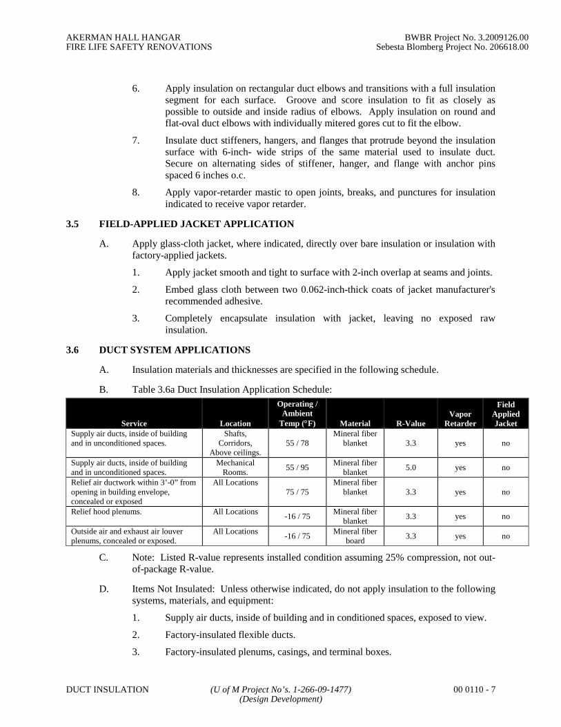
AKERMAN HALL HANGAR BWBR Project No. 3.2009126.00FIRE LIFE SAFETY RENOVATIONS Sebesta Blomberg Project No. 206618.00
DUCT INSULATION (U of M Project No’s. 1-266-09-1477) 00 0110 - 7(Design Development)
6. Apply insulation on rectangular duct elbows and transitions with a full insulationsegment for each surface. Groove and score insulation to fit as closely aspossible to outside and inside radius of elbows. Apply insulation on round andflat-oval duct elbows with individually mitered gores cut to fit the elbow.
7. Insulate duct stiffeners, hangers, and flanges that protrude beyond the insulationsurface with 6-inch- wide strips of the same material used to insulate duct.Secure on alternating sides of stiffener, hanger, and flange with anchor pinsspaced 6 inches o.c.
8. Apply vapor-retarder mastic to open joints, breaks, and punctures for insulationindicated to receive vapor retarder.
3.5 FIELD-APPLIED JACKET APPLICATION
A. Apply glass-cloth jacket, where indicated, directly over bare insulation or insulation withfactory-applied jackets.
1. Apply jacket smooth and tight to surface with 2-inch overlap at seams and joints.
2. Embed glass cloth between two 0.062-inch-thick coats of jacket manufacturer'srecommended adhesive.
3. Completely encapsulate insulation with jacket, leaving no exposed rawinsulation.
3.6 DUCT SYSTEM APPLICATIONS
A. Insulation materials and thicknesses are specified in the following schedule.
B. Table 3.6a Duct Insulation Application Schedule:
Service Location
Operating /Ambient
Temp (F) Material R-ValueVapor
Retarder
FieldAppliedJacket
Supply air ducts, inside of buildingand in unconditioned spaces.
Shafts,Corridors,
Above ceilings.55 / 78
Mineral fiberblanket 3.3 yes no
Supply air ducts, inside of buildingand in unconditioned spaces.
MechanicalRooms.
55 / 95Mineral fiber
blanket5.0 yes no
Relief air ductwork within 3’-0” fromopening in building envelope,concealed or exposed
All Locations75 / 75
Mineral fiberblanket 3.3 yes no
Relief hood plenums. All Locations-16 / 75
Mineral fiberblanket
3.3 yes no
Outside air and exhaust air louverplenums, concealed or exposed.
All Locations-16 / 75
Mineral fiberboard
3.3 yes no
C. Note: Listed R-value represents installed condition assuming 25% compression, not out-of-package R-value.
D. Items Not Insulated: Unless otherwise indicated, do not apply insulation to the followingsystems, materials, and equipment:
1. Supply air ducts, inside of building and in conditioned spaces, exposed to view.
2. Factory-insulated flexible ducts.
3. Factory-insulated plenums, casings, and terminal boxes.

AKERMAN HALL HANGAR BWBR Project No. 3.2009126.00FIRE LIFE SAFETY RENOVATIONS Sebesta Blomberg Project No. 206618.00
DUCT INSULATION (U of M Project No’s. 1-266-09-1477) 00 0110 - 8(Design Development)
4. Flexible connectors.
5. Vibration-control devices.
6. Testing agency labels and stamps.
7. Nameplates and data plates.
8. Access panels and doors in air-distribution systems.
END OF SECTION

AKERMAN HALL HANGAR BWBR Project No. 3.2009126.00FIRE LIFE SAFETY RENOVATIONS Sebesta Blomberg Project No. 206618.00
HVAC EQUIPMENT INSULATION (U of M Project No’s. 1-266-09-1477) 23 0716- 1(Design Development)
SECTION 23 0716
HVAC EQUIPMENT INSULATION
PART 1 - GENERAL
1.1 RELATED DOCUMENTS
A. Drawings and general provisions of the Contract, including General and SupplementaryConditions and Division 1 Specification Sections, apply to this Section.
1.2 SUMMARY
A. This Section includes blanket, board, and block insulation; insulating cements; field-applied jackets; accessories and attachments; and sealing compounds.
B. Related Sections include the following:
1. Division 23 Section "Duct Insulation" for insulation materials and application forducts and plenums.
2. Division 23 Section "HVAC Pipe Insulation" for insulation for piping systems.
1.3 SUBMITTALS
A. Product Data: Identify thermal conductivity, thickness, and jackets (both factory andfield applied, if any), for each type of product indicated.
B. Shop Drawings: Show fabrication and installation details for the following:
1. Field application for each equipment type.
2. Removable insulation sections at access panels.
3. Application of field-applied jackets.
C. Material Test Reports: From a qualified testing agency acceptable to authorities havingjurisdiction indicating, interpreting, and certifying test results for compliance of insula-tion materials, sealers, attachments, cements, and jackets with requirements indicated.Include dates of tests.
D. Installer Certificates: Signed by the Contractor certifying that installers comply with re-quirements.
1.4 QUALITY ASSURANCE
A. Installer Qualifications: Skilled mechanics who have successfully completed an appren-ticeship program or another craft training program certified by the U.S. Department ofLabor, Bureau of Apprenticeship and Training.
B. Fire-Test-Response Characteristics: As determined by testing materials identical to thosespecified in this Section according to ASTM E 84, by a testing and inspecting agency ac-ceptable to authorities having jurisdiction. Factory label insulation and jacket materials

AKERMAN HALL HANGAR BWBR Project No. 3.2009126.00FIRE LIFE SAFETY RENOVATIONS Sebesta Blomberg Project No. 206618.00
HVAC EQUIPMENT INSULATION (U of M Project No’s. 1-266-09-1477) 23 0716- 2(Design Development)
and sealer and cement material containers with appropriate markings of applicable testingand inspecting agency.
1. Insulation Installed Indoors: Flame-spread rating of 25 or less, and smoke-developed rating of 50 or less.
2. Insulation Installed Outdoors: Flame-spread rating of 75 or less, and smoke-developed rating of 150 or less.
1.5 DELIVERY, STORAGE, AND HANDLING
A. Packaging: Ship insulation materials in containers marked by manufacturer with appro-priate ASTM specification designation, type and grade, and maximum use temperature.
1.6 COORDINATION
A. Coordinate clearance requirements with equipment Installer for insulation application.
PART 2 - PRODUCTS
2.1 MANUFACTURERS
A. Manufacturers: Subject to compliance with requirements, provide products by one of thefollowing:
1. Mineral-Fiber Insulation:
a. CertainTeed Manson.
b. Knauf FiberGlass GmbH.
c. Owens-Corning Fiberglas Corp.
d. Schuller International, Inc.
2.2 INSULATION MATERIALS
A. Mineral-Fiber Board Thermal Insulation: Glass fibers bonded with a thermosetting resin.Comply with ASTM C 612, Type IB, without facing and with all-service jacket manufac-tured from kraft paper, reinforcing scrim, aluminum foil, and vinyl film.
B. Mineral-Fiber Blanket Thermal Insulation: Glass fibers bonded with a thermosetting re-sin. Comply with ASTM C 553, Type II, without facing and with all-service jacket man-ufactured from kraft paper, reinforcing scrim, aluminum foil, and vinyl film.
2.3 ACCESSORIES AND ATTACHMENTS
A. Glass Cloth and Tape: Comply with MIL-C-20079H, Type I for cloth and Type II fortape. Woven glass-fiber fabrics, plain weave, presized a minimum of 8 oz./sq. yd..
1. Tape Width: 4 inches.
B. Bands: 3/4 inch wide, in one of the following materials compatible with jacket:
1. Stainless Steel: ASTM A 666, Type 304; 0.020 inch thick.
2. Galvanized Steel: 0.005 inch thick.

AKERMAN HALL HANGAR BWBR Project No. 3.2009126.00FIRE LIFE SAFETY RENOVATIONS Sebesta Blomberg Project No. 206618.00
HVAC EQUIPMENT INSULATION (U of M Project No’s. 1-266-09-1477) 23 0716- 3(Design Development)
3. Aluminum: 0.007 inch thick.
4. Brass: 0.010 inch thick.
5. Nickel-Copper Alloy: 0.005 inch thick.
C. Wire: 0.080-inch, nickel-copper alloy; 0.062-inch, soft-annealed, stainless steel; or0.062-inch, soft-annealed, galvanized steel.
D. Self-Adhesive Anchor Pins and Speed Washers: Galvanized steel plant, pin and washermanufactured for attachment to duct and plenum with adhesive. Pin length sufficient forinsulation thickness indicated.
2.4 VAPOR RETARDERS
A. Mastics: Materials recommended by insulation material manufacturer that are compati-ble with insulation materials, jackets, and substrates.
PART 3 - EXECUTION
3.1 EXAMINATION
A. Examine substrates and conditions for compliance with requirements for installation andother conditions affecting performance of insulation application.
B. Proceed with installation only after unsatisfactory conditions have been corrected.
3.2 PREPARATION
A. Surface Preparation: Clean and dry surfaces to receive insulation. Remove materials thatwill adversely affect insulation application.
3.3 GENERAL APPLICATION REQUIREMENTS
A. Apply insulation materials, accessories, and finishes according to the manufacturer's writ-ten instructions; with smooth, straight, and even surfaces; and free of voids throughoutthe length of equipment.
B. Refer to schedules at the end of this Section for materials, forms, jackets, and thicknessesrequired for each equipment system.
C. Use accessories compatible with insulation materials and suitable for the service. Useaccessories that do not corrode, soften, or otherwise attack insulation or jacket in eitherthe wet or dry state.
D. Apply multiple layers of insulation with longitudinal and end seams staggered.
E. Seal joints and seams with vapor-retarder mastic on insulation indicated to receive a va-por retarder.
F. Keep insulation materials dry during application and finishing.
G. Apply insulation with tight longitudinal seams and end joints. Bond seams and jointswith adhesive recommended by the insulation material manufacturer.

AKERMAN HALL HANGAR BWBR Project No. 3.2009126.00FIRE LIFE SAFETY RENOVATIONS Sebesta Blomberg Project No. 206618.00
HVAC EQUIPMENT INSULATION (U of M Project No’s. 1-266-09-1477) 23 0716- 4(Design Development)
H. Apply insulation with the least number of joints practical.
I. Apply insulation over fittings and specialties, with continuous thermal and vapor-retarderintegrity, unless otherwise indicated.
J. Hangers and Anchors: Where vapor retarder is indicated, seal penetrations in insulationat hangers, supports, anchors, and other projections with vapor-retarder mastic. Applyinsulation continuously through hangers and around anchor attachments.
K. Insulation Terminations: For insulation application where vapor retarders are indicated,seal ends with a compound recommended by the insulation material manufacturer tomaintain vapor retarder.
L. Apply insulation with integral jackets as follows:
1. Pull jacket tight and smooth.
2. Joints and Seams: Cover with tape and vapor retarder as recommended by insu-lation material manufacturer to maintain vapor seal.
3. Vapor-Retarder Mastics: Where vapor retarders are indicated, apply mastic onseams and joints and at ends adjacent to flanges and fittings.
M. Cut insulation according to manufacturer's written instructions to prevent compressinginsulation to less than 75 percent of its nominal thickness.
N. Install vapor-retarder mastic on equipment scheduled to receive vapor retarders. Overlapinsulation facing at seams and seal with vapor-retarder mastic and pressure-sensitive tapehaving same facing as insulation. Repair punctures, tears, and penetrations with tape ormastic to maintain vapor-retarder seal.
O. Insulate the following indoor equipment:
1. Heating hot-water and chilled water air separators (small tanks).
2. Steam-to-water converters, not factory insulated.
3. Chilled water pump bodies.
P. Omit insulation from the following:
1. Vibration-control devices.
2. Testing agency labels and stamps.
3. Nameplates and data plates.
4. Manholes.
5. Handholes.
6. Cleanouts.
3.4 FIELD QUALITY CONTROL
A. Inspection: Perform the following field quality-control inspections, after installing insu-lation materials, jackets, and finishes, to determine compliance with requirements:
1. Inspect pumps and tanks randomly selected by Engineer.

AKERMAN HALL HANGAR BWBR Project No. 3.2009126.00FIRE LIFE SAFETY RENOVATIONS Sebesta Blomberg Project No. 206618.00
HVAC EQUIPMENT INSULATION (U of M Project No’s. 1-266-09-1477) 23 0716- 5(Design Development)
2. Remove insulation and covers from two small tanks or one percent of smalltanks, whichever is greater.
B. Insulation applications will be considered defective if sample inspection reveals noncom-pliance with requirements. Remove defective Work and replace with new materials ac-cording to these Specifications.
C. Reinstall insulation and covers on pumps and tanks uncovered for inspection according tothese Specifications.
3.5 EQUIPMENT APPLICATIONS
A. Insulation materials and thickness are specified in schedules at the end of this Section.
B. Materials and thickness for systems listed below are specified in schedules at the end ofthis Section.
3.6 INTERIOR TANK AND VESSEL INSULATION APPLICATION SCHEDULE
A. Equipment: Heating hot-water air separators..
1. Operating Temperature: 100 to 200 deg F.
2. Insulation Material: Mineral fiber, with jacket.
3. Insulation Thickness: 1-1/2 inch
4. Field-Applied Jacket: No.
5. Vapor Retarder Required: No.
6. Finish: None.
B. Equipment: Steam-to-water converters.
1. Operating Temperature: 100 to 450 deg F.
2. Insulation Material: Mineral fiber.
3. Insulation Thickness: 3 inch
4. Field-Applied Jacket: No.
5. Vapor Retarder Required: No.
6. Finish: None.
END OF SECTION 23 0716

AKERMAN HALL HANGAR BWBR Project No. 3.2009126.00FIRE LIFE SAFETY RENOVATIONS Sebesta Blomberg Project No. 206618.00
HVAC PIPE INSULATION (U of M Project No’s. 1-266-09-1477) 23 0719 - 1(Design Development)
SECTION 23 07 19
HVAC PIPE INSULATION
PART 1 - GENERAL
1.1 RELATED DOCUMENTS
A. Drawings and general provisions of the Contract, including General and SupplementaryConditions and Division 1 Specification Sections, apply to this Section.
1.2 SUMMARY
A. This Section includes preformed, rigid and flexible pipe insulation; insulating cements;field-applied jackets; accessories and attachments; and sealing compounds for new andexisting piping.
B. Related Sections include the following:
1. Division 7 Section "Penetration Firestopping" for firestopping materials andrequirements for penetrations through fire and smoke barriers.
2. Division 23 Section "HVAC Duct Insulation" for insulation for ducts andplenums.
3. Division 23 Section "HVAC Equipment Insulation" for insulation materials andapplication for pumps, tanks, hydronic specialties, and other equipment.
4. Division 23 Section "HVAC Hangers and Supports" for pipe insulation shieldsand protection saddles.
1.3 SUBMITTALS
A. Product Data: Identify thermal conductivity, thickness, and jackets (both factory andfield applied, if any), for each type of product indicated.
B. Material Test Reports: From a qualified testing agency acceptable to authorities havingjurisdiction indicating, interpreting, and certifying test results for compliance ofinsulation materials, sealers, attachments, cements, and jackets with requirementsindicated. Include dates of tests.
C. Installer Certificates: Signed by the Contractor certifying that installers comply withrequirements.
1.4 QUALITY ASSURANCE
A. Installer Qualifications: Skilled mechanics who have successfully completed anapprenticeship program or another craft training program certified by the U.S.Department of Labor, Bureau of Apprenticeship and Training.
B. Fire-Test-Response Characteristics: As determined by testing materials identical to thosespecified in this Section according to ASTM E 84, by a testing and inspecting agency

AKERMAN HALL HANGAR BWBR Project No. 3.2009126.00FIRE LIFE SAFETY RENOVATIONS Sebesta Blomberg Project No. 206618.00
HVAC PIPE INSULATION (U of M Project No’s. 1-266-09-1477) 23 0719 - 2(Design Development)
acceptable to authorities having jurisdiction. Factory label insulation and jacket materialsand sealer and cement material containers with appropriate markings of applicable testingand inspecting agency.
1. Insulation Installed Indoors: Flame-spread rating of 25 or less, and smoke-developed rating of 50 or less.
2. Insulation Installed Outdoors: Flame-spread rating of 75 or less, and smoke-developed rating of 150 or less.
1.5 DELIVERY, STORAGE, AND HANDLING
A. Packaging: Ship insulation materials in containers marked by manufacturer withappropriate ASTM specification designation, type and grade, and maximum usetemperature.
1.6 COORDINATION
A. Coordinate size and location of supports, hangers, and insulation shields specified inDivision 23 Section "HVAC Hangers and Supports."
B. Coordinate clearance requirements with piping Installer for insulation application.
1.7 SCHEDULING
A. Schedule insulation application after testing piping systems and, where required, afterinstalling and testing heat-trace tape. Insulation application may begin on segments ofpiping that have satisfactory test results.
PART 2 - PRODUCTS
2.1 MANUFACTURERS
A. Manufacturers: Subject to compliance with requirements, provide products by one of thefollowing:
1. Mineral-Fiber/Mineral Wool Insulation:
a. CertainTeed Manson.
b. Knauf FiberGlass GmbH.
c. Owens-Corning Fiberglas Corp.
d. Schuller International, Inc.
2. Cellular-Glass Insulation:
a. Pittsburgh-Corning Corp.
3. Flexible Elastomeric Thermal Insulation:
a. Armstrong World Industries, Inc.
b. Rubatex Corp.
4. Polyolefin Insulation:
a. Armstrong World Industries, Inc.

AKERMAN HALL HANGAR BWBR Project No. 3.2009126.00FIRE LIFE SAFETY RENOVATIONS Sebesta Blomberg Project No. 206618.00
HVAC PIPE INSULATION (U of M Project No’s. 1-266-09-1477) 23 0719 - 3(Design Development)
b. IMCOA.
5. Calcium Silicate Insulation:
a. Owens-Corning Fiberglas Corp.
b. Pabco.
c. Schuller International, Inc.
2.2 INSULATION MATERIALS
A. Mineral-Fiber Insulation: Glass fibers bonded with a thermosetting resin complying withthe following:
1. Preformed Pipe Insulation: Comply with ASTM C 547, Type 1, with factory-applied, all-purpose, vapor-retarder jacket.
2. Blanket Insulation: Comply with ASTM C 553, Type II, without facing.
3. Fire-Resistant Adhesive: Comply with MIL-A-3316C in the following classesand grades:
a. Class 1, Grade A for bonding glass cloth and tape to unfaced glass-fiberinsulation, for sealing edges of glass-fiber insulation, and for bondinglagging cloth to unfaced glass-fiber insulation.
b. Class 2, Grade A for bonding glass-fiber insulation to metal surfaces.
4. Vapor-Retarder Mastics: Fire- and water-resistant, vapor-retarder mastic forindoor applications. Comply with MIL-C-19565C, Type II.
5. Mineral-Fiber Insulating Cements: Comply with ASTM C 195.
6. Expanded or Exfoliated Vermiculite Insulating Cements: Comply withASTM C 196.
7. Mineral-Fiber, Hydraulic-Setting Insulating and Finishing Cement: Comply withASTM C 449/.
B. Mineral-Fiber (Fiberglass) Insulation: Glass fibers bonded with a thermosetting resincomplying with the following:
1. Preformed Pipe Insulation: Comply with ASTM C 547, Type I, (850 ºF),minimum density 3 lb/ft³, with factory-applied, 11 oz canvas jacket.
2. Fire-Resistant Adhesive: Comply with MIL-A-3316C in the following classesand grades:
a. Class 1, Grade A for bonding glass cloth and tape to unfaced glass-fiberinsulation, for sealing edges of glass-fiber insulation, and for bondinglagging cloth to unfaced glass-fiber insulation.
b. Class 2, Grade A for bonding glass-fiber insulation to metal surfaces.
3. Vapor-Retarder Mastics: Fire- and water-resistant, vapor-retarder mastic forindoor applications. Comply with MIL-C-19565C, Type II.
4. Mineral-Fiber Insulating Cements: Comply with ASTM C 195.

AKERMAN HALL HANGAR BWBR Project No. 3.2009126.00FIRE LIFE SAFETY RENOVATIONS Sebesta Blomberg Project No. 206618.00
HVAC PIPE INSULATION (U of M Project No’s. 1-266-09-1477) 23 0719 - 4(Design Development)
5. Mineral-Fiber, Hydraulic-Setting Insulating and Finishing Cement: Comply withASTM C 449.
C. Cellular-Glass Insulation: Inorganic, foamed or cellulated glass, annealed, rigid,hermetically sealed cells, incombustible.
1. Preformed Pipe Insulation, without Jacket: Comply with ASTM C 552, Type II,Class 1.
2. Preformed Pipe Insulation, with Jacket: Comply with ASTM C 552, Type II,Class 2.
D. Flexible Elastomeric Thermal Insulation: Closed-cell, sponge- or expanded-rubbermaterials. Comply with ASTM C 534, Type I for tubular materials and Type II for sheetmaterials.
1. Adhesive: As recommended by insulation material manufacturer.
2. Ultraviolet-Protective Coating: As recommended by insulation manufacturer.
E. Polyolefin Insulation: Unicellular polyethylene thermal plastic, preformed pipeinsulation. Comply with ASTM C 534, Type I, except for density.
1. Adhesive: As recommended by insulation material manufacturer.
F. Calcium Silicate Insulation: Preformed pipe sections of noncombustible, inorganic,hydrous calcium silicate with a nonasbestos fibrous reinforcement. Comply withASTM C 533, Type I.
G. Prefabricated Thermal Insulating Fitting Covers: Comply with ASTM C 450 fordimensions used in preforming insulation to cover valves, elbows, tees, and flanges.
2.3 FIELD-APPLIED JACKETS
A. General: ASTM C 921, Type 1, unless otherwise indicated.
B. Foil and Paper Jacket: Laminated, glass-fiber-reinforced, flame-retardant kraft paper andaluminum foil.
C. PVC Jacket: High-impact, ultraviolet-resistant PVC; 20 mils thick; roll stock ready forshop or field cutting and forming.
1. Adhesive: As recommended by insulation material manufacturer.
2. PVC Jacket Color: White or gray.

AKERMAN HALL HANGAR BWBR Project No. 3.2009126.00FIRE LIFE SAFETY RENOVATIONS Sebesta Blomberg Project No. 206618.00
HVAC PIPE INSULATION (U of M Project No’s. 1-266-09-1477) 23 0719 - 5(Design Development)
D. Standard PVC Fitting Covers: Factory-fabricated fitting covers manufactured from 20-mil- thick, high-impact, ultraviolet-resistant PVC.
1. Shapes: 45- and 90-degree, short- and long-radius elbows, tees, valves, flanges,reducers, end caps, soil-pipe hubs, traps, mechanical joints, and P-trap and supplycovers for lavatories for the disabled.
2. Adhesive: As recommended by insulation material manufacturer.
E. Aluminum Jacket: Factory cut and rolled to sizes indicated. Comply with ASTM B 209,3003 alloy, H-14 temper.
1. Finish and Thickness: Corrugated finish, 0.010 inch thick.
2. Moisture Barrier: 1-mil- thick, heat-bonded polyethylene and kraft paper.
3. Elbows: Preformed, 45- and 90-degree, short- and long-radius elbows; samematerial, finish, and thickness as jacket.
2.4 ACCESSORIES AND ATTACHMENTS
A. Glass Cloth and Tape: Comply with MIL-C-20079H, Type I for cloth and Type II fortape. Woven glass-fiber fabrics, plain weave, presized a minimum of 8 oz./sq. yd..
1. Tape Width: 4 inches.
B. Bands: 3/4 inch wide, in one of the following materials compatible with jacket:
1. Stainless Steel: ASTM A 666, Type 304; 0.020 inch thick.
2. Galvanized Steel: 0.005 inch thick.
3. Aluminum: 0.007 inch thick.
4. Brass: 0.010 inch thick.
5. Nickel-Copper Alloy: 0.005 inch thick.
C. Wire: 0.080-inch, nickel-copper alloy; 0.062-inch, soft-annealed, stainless steel; or0.062-inch, soft-annealed, galvanized steel.
2.5 VAPOR RETARDERS
A. Mastics: Materials recommended by insulation material manufacturer that arecompatible with insulation materials, jackets, and substrates.
PART 3 - EXECUTION
3.1 EXAMINATION
A. Examine substrates and conditions for compliance with requirements for installation andother conditions affecting performance of insulation application.
B. Proceed with installation only after unsatisfactory conditions have been corrected.

AKERMAN HALL HANGAR BWBR Project No. 3.2009126.00FIRE LIFE SAFETY RENOVATIONS Sebesta Blomberg Project No. 206618.00
HVAC PIPE INSULATION (U of M Project No’s. 1-266-09-1477) 23 0719 - 6(Design Development)
3.2 PREPARATION
A. Surface Preparation: Clean and dry pipe and fitting surfaces. Remove materials that willadversely affect insulation application.
3.3 GENERAL APPLICATION REQUIREMENTS
A. Apply insulation materials, accessories, and finishes according to the manufacturer'swritten instructions; with smooth, straight, and even surfaces; free of voids throughoutthe length of piping, including fittings, valves, and specialties.
B. Refer to schedules at the end of this Section for materials, forms, jackets, and thicknessesrequired for each piping system.
C. Use accessories compatible with insulation materials and suitable for the service. Useaccessories that do not corrode, soften, or otherwise attack insulation or jacket in eitherwet or dry state.
D. Apply insulation with longitudinal seams at top and bottom of horizontal pipe runs.
E. Apply multiple layers of insulation with longitudinal and end seams staggered.
F. Do not weld brackets, clips, or other attachment devices to piping, fittings, andspecialties.
G. Seal joints and seams with vapor-retarder mastic on insulation indicated to receive avapor retarder.
H. Keep insulation materials dry during application and finishing.
I. Apply insulation with tight longitudinal seams and end joints. Bond seams and jointswith adhesive recommended by the insulation material manufacturer.
J. Apply insulation with the least number of joints practical.
K. Apply insulation over fittings, valves, and specialties, with continuous thermal and vapor-retarder integrity, unless otherwise indicated. Refer to special instructions for applyinginsulation over fittings, valves, and specialties.
L. Hangers and Anchors: Where vapor retarder is indicated, seal penetrations in insulationat hangers, supports, anchors, and other projections with vapor-retarder mastic.
1. Apply insulation continuously through hangers and around anchor attachments.
2. For insulation application where vapor retarders are indicated, extend insulationon anchor legs at least 12 inches from point of attachment to pipe and taperinsulation ends. Seal tapered ends with a compound recommended by theinsulation material manufacturer to maintain vapor retarder.
3. Install insert materials and apply insulation to tightly join the insert. Sealinsulation to insulation inserts with adhesive or sealing compound recommendedby the insulation material manufacturer.

AKERMAN HALL HANGAR BWBR Project No. 3.2009126.00FIRE LIFE SAFETY RENOVATIONS Sebesta Blomberg Project No. 206618.00
HVAC PIPE INSULATION (U of M Project No’s. 1-266-09-1477) 23 0719 - 7(Design Development)
4. Cover inserts with jacket material matching adjacent pipe insulation. Installshields over jacket, arranged to protect the jacket from tear or puncture by thehanger, support, and shield.
M. Insulation Terminations: For insulation application where vapor retarders are indicated,taper insulation ends. Seal tapered ends with a compound recommended by theinsulation material manufacturer to maintain vapor retarder.
N. Apply adhesives and mastics at the manufacturer's recommended coverage rate.
O. Apply insulation with integral jackets as follows:
1. Pull jacket tight and smooth.
2. Circumferential Joints: Cover with 3-inch- wide strips, of same material asinsulation jacket. Secure strips with adhesive and outward clinching staplesalong both edges of strip and spaced 4 inches o.c.
3. Longitudinal Seams: Overlap jacket seams at least 1-1/2 inches. Applyinsulation with longitudinal seams at bottom of pipe. Clean and dry surface toreceive self-sealing lap. Staple laps with outward clinching staples along edge at4 inches o.c.
a. Exception: Do not staple longitudinal laps on insulation having a vaporretarder.
4. Vapor-Retarder Mastics: Where vapor retarders are indicated, apply mastic onseams and joints and at ends adjacent to flanges, unions, valves, and fittings.
5. At penetrations in jackets for thermometers and pressure gages, fill and sealvoids with vapor-retarder mastic.
P. Roof Penetrations: Apply insulation for interior applications to a point even with top ofroof flashing.
1. Seal penetrations with vapor-retarder mastic.
2. Apply insulation for exterior applications tightly joined to interior insulationends.
3. Extend metal jacket of exterior insulation outside roof flashing at least 2 inchesbelow top of roof flashing.
4. Seal metal jacket to roof flashing with vapor-retarder mastic.
Q. Exterior Wall Penetrations: For penetrations of below-grade exterior walls, terminateinsulation flush with mechanical sleeve seal. Seal terminations with vapor-retardermastic.
R. Interior Wall and Partition Penetrations: Apply insulation continuously through wallsand floors.
S. Fire-Rated Wall and Partition Penetrations: Apply insulation continuously throughpenetrations of fire-rated walls and partitions.
1. Firestopping and fire-resistive joint sealers are specified in Division 7 Section"Firestopping."

AKERMAN HALL HANGAR BWBR Project No. 3.2009126.00FIRE LIFE SAFETY RENOVATIONS Sebesta Blomberg Project No. 206618.00
HVAC PIPE INSULATION (U of M Project No’s. 1-266-09-1477) 23 0719 - 8(Design Development)
T. Floor Penetrations: Apply insulation continuously through floor assembly.
1. For insulation with vapor retarders, seal insulation with vapor-retarder masticwhere floor supports penetrate vapor retarder.
3.4 MINERAL-FIBER INSULATION APPLICATION
A. Apply insulation to straight pipes and tubes as follows:
1. Secure each layer of preformed pipe insulation to pipe with wire, tape, or bandswithout deforming insulation materials.
2. Where vapor retarders are indicated, seal longitudinal seams and end joints withvapor-retarder mastic. Apply vapor retarder to ends of insulation at intervals of15 to 20 feet to form a vapor retarder between pipe insulation segments.
3. For insulation with factory-applied jackets, secure laps with outward clinchedstaples at 6 inches o.c.
4. For insulation with factory-applied jackets with vapor retarders, do not staplelongitudinal tabs but secure tabs with additional adhesive as recommended by theinsulation material manufacturer and seal with vapor-retarder mastic.
B. Apply insulation to flanges as follows:
1. Apply preformed pipe insulation to outer diameter of pipe flange.
2. Make width of insulation segment the same as overall width of the flange andbolts, plus twice the thickness of the pipe insulation.
3. Fill voids between inner circumference of flange insulation and outercircumference of adjacent straight pipe segments with mineral-fiber blanketinsulation.
4. Apply canvas jacket material with manufacturer's recommended adhesive,overlapping seams at least 1 inch, and seal joints with vapor-retarder mastic.
C. Apply insulation to fittings and elbows as follows:
1. Apply premolded insulation sections of the same material as straight segments ofpipe insulation when available. Secure according to manufacturer's writteninstructions.
2. When premolded insulation elbows and fittings are not available, apply miteredsections of pipe insulation, or glass-fiber blanket insulation, to a thickness equalto adjoining pipe insulation. Secure insulation materials with wire, tape, orbands.
3. Cover fittings with heavy PVC fitting covers. Overlap PVC covers on pipeinsulation jackets at least 1 inch at each end. Secure fitting covers withmanufacturer's attachments and accessories. Seal seams with tape and vapor-retarder mastic.
D. Apply insulation to valves and specialties as follows:
1. Apply premolded insulation sections of the same material as straight segments ofpipe insulation when available. Secure according to manufacturer's writteninstructions.
AKERMAN HALL HANGAR BWBR Project No. 3.2009126.00FIRE LIFE SAFETY RENOVATIONS Sebesta Blomberg Project No. 206618.00
HVAC PIPE INSULATION (U of M Project No’s. 1-266-09-1477) 23 0719 - 9(Design Development)
2. When premolded insulation sections are not available, apply glass-fiber blanketinsulation to valve body. Arrange insulation to permit access to packing and toallow valve operation without disturbing insulation. For check valves, arrangeinsulation for access to stainer basket without disturbing insulation.
3. Apply insulation to flanges as specified for flange insulation application.
4. Use preformed heavy PVC fitting covers for valve sizes where available. Securefitting covers with manufacturer's attachments and accessories. Seal seams withtape and vapor-retarder mastic.
5. For larger sizes where PVC fitting covers are not available, seal insulation withcanvas jacket and sealing compound recommended by the insulation materialmanufacturer.
3.5 CELLULAR-GLASS INSULATION APPLICATION
A. Apply insulation to straight pipes and tubes as follows:
1. Secure each layer of insulation to pipe with wire, tape, or bands withoutdeforming insulation materials.
2. Where vapor retarders are indicated, seal longitudinal seams and end joints withvapor-retarder mastic.
3. For insulation with factory-applied jackets, secure laps with outward clinchedstaples at 6 inches o.c.
4. For insulation with factory-applied jackets with vapor retarders, do not staplelongitudinal tabs but secure tabs with additional adhesive as recommended by theinsulation material manufacturer and seal with vapor-retarder mastic.
B. Apply insulation to flanges as follows:
1. Apply preformed pipe insulation to outer diameter of pipe flange.
2. Make width of insulation segment the same as overall width of the flange andbolts, plus twice the thickness of the pipe insulation.
3. Fill voids between inner circumference of flange insulation and outercircumference of adjacent straight pipe segments with cut sections of cellular-glass block insulation of the same thickness as pipe insulation.
4. Apply canvas jacket material with manufacturer's recommended adhesive,overlapping seams at least 1 inch, and seal joints with vapor-retarder mastic.
C. Apply insulation to fittings and elbows as follows:
1. Apply premolded insulation sections of the same material as straight segments ofpipe insulation when available. Secure according to manufacturer's writteninstructions.
2. When premolded sections of insulation are not available, apply mitered sectionsof cellular-glass insulation. Secure insulation materials with wire, tape, or bands.
3. Cover fittings with heavy PVC fitting covers. Overlap PVC covers on pipeinsulation jackets at least 1 inch at each end. Secure fitting covers with

AKERMAN HALL HANGAR BWBR Project No. 3.2009126.00FIRE LIFE SAFETY RENOVATIONS Sebesta Blomberg Project No. 206618.00
HVAC PIPE INSULATION (U of M Project No’s. 1-266-09-1477) 23 0719 - 10(Design Development)
manufacturer's attachments and accessories. Seal seams with tape and vapor-retarder mastic.
D. Apply insulation to valves and specialties as follows:
1. Apply premolded segments of cellular-glass insulation or glass-fiber blanketinsulation to valve body. Arrange insulation to permit access to packing and toallow valve operation without disturbing insulation. For check valves, arrangeinsulation for access to stainer basket without disturbing insulation.
2. Apply insulation to flanges as specified for flange insulation application.
3. Use preformed heavy PVC fitting covers for valve sizes where available. Securefitting covers with manufacturer's attachments and accessories. Seal seams withtape and vapor-retarder mastic.
4. For larger sizes where PVC fitting covers are not available, seal insulation withcanvas jacket and sealing compound recommended by the insulation materialmanufacturer.
3.6 FLEXIBLE ELASTOMERIC THERMAL INSULATION APPLICATION
A. Apply insulation to straight pipes and tubes as follows:
1. Follow manufacturer's written instructions for applying insulation.
2. Seal longitudinal seams and end joints with manufacturer's recommendedadhesive. Cement to avoid openings in insulation that will allow passage of airto the pipe surface.
B. Apply insulation to flanges as follows:
1. Apply pipe insulation to outer diameter of pipe flange.
2. Make width of insulation segment the same as overall width of the flange andbolts, plus twice the thickness of the pipe insulation.
3. Fill voids between inner circumference of flange insulation and outercircumference of adjacent straight pipe segments with cut sections of sheetinsulation of the same thickness as pipe insulation.
4. Secure insulation to flanges and seal seams with manufacturer's recommendedadhesive. Cement to avoid openings in insulation that will allow passage of airto the pipe surface.
C. Apply insulation to fittings and elbows as follows:
1. Apply mitered sections of pipe insulation.
2. Secure insulation materials and seal seams with manufacturer's recommendedadhesive. Cement to avoid openings in insulation that will allow passage of airto the pipe surface.
D. Apply insulation to valves and specialties as follows:
1. Apply preformed valve covers manufactured of the same material as pipeinsulation and attached according to the manufacturer's written instructions.
AKERMAN HALL HANGAR BWBR Project No. 3.2009126.00FIRE LIFE SAFETY RENOVATIONS Sebesta Blomberg Project No. 206618.00
HVAC PIPE INSULATION (U of M Project No’s. 1-266-09-1477) 23 0719 - 11(Design Development)
2. Apply cut segments of pipe and sheet insulation to valve body. Arrangeinsulation to permit access to packing and to allow valve operation withoutdisturbing insulation. For check valves, fabricate removable sections ofinsulation arranged to allow access to stainer basket.
3. Apply insulation to flanges as specified for flange insulation application.
4. Secure insulation to valves and specialties and seal seams with manufacturer'srecommended adhesive. Cement to avoid openings in insulation that will allowpassage of air to the pipe surface.
3.7 CALCIUM SILICATE INSULATION APPLICATION
A. Apply insulation to straight pipes and tubes as follows:
1. Secure each layer of insulation to pipe with stainless-steel bands at 12-inchintervals and tighten without deforming insulation materials.
2. Apply two-layer insulation with joints tightly butted and staggered at least 3inches. Secure inner layer with 0.062-inch, soft-annealed, stainless-steel wirespaced at 12-inch intervals. Secure outer layer with stainless-steel bands at 12-inch intervals.
3. Apply a skim coat of mineral-fiber, hydraulic-setting cement to surface ofinstalled insulation. When dry, apply flood coat of lagging adhesive and press onone layer of glass cloth or tape. Overlap edges at least 1 inch. Apply finish coatof lagging adhesive over glass cloth or tape. Thin the finish coat to achievesmooth finish.
B. Apply insulation to flanges as follows:
1. Apply preformed pipe insulation to outer diameter of pipe flange.
2. Make width of insulation segment the same as overall width of the flange andbolts, plus twice the thickness of the pipe insulation.
3. Fill voids between inner circumference of flange insulation and outercircumference of adjacent straight pipe segments with cut sections of blockinsulation of the same material and thickness as pipe insulation.
4. Finish flange insulation the same as pipe insulation.
C. Apply insulation to fittings and elbows as follows:
1. Apply premolded insulation sections of the same material as straight segments ofpipe insulation when available. Secure according to manufacturer's writteninstructions.
2. When premolded sections of insulation are not available, apply mitered sectionsof calcium silicate insulation. Secure insulation materials with stainless-steelwire.
3. Finish insulation of fittings the same as pipe insulation.
D. Apply insulation to valves and specialties as follows:
1. Apply mitered segments of calcium silicate insulation to valve body. Arrangeinsulation to permit access to packing and to allow valve operation without
AKERMAN HALL HANGAR BWBR Project No. 3.2009126.00FIRE LIFE SAFETY RENOVATIONS Sebesta Blomberg Project No. 206618.00
HVAC PIPE INSULATION (U of M Project No’s. 1-266-09-1477) 23 0719 - 12(Design Development)
disturbing insulation. For check valves, arrange insulation for access to stainerbasket without disturbing insulation.
2. Apply insulation to flanges as specified for flange insulation application.
3. Finish valve and specialty insulation the same as pipe insulation.
3.8 FIELD-APPLIED JACKET APPLICATION
A. Apply glass-cloth jacket, where indicated, directly over bare insulation or insulation withfactory-applied jackets.
1. Apply jacket smooth and tight to surface with 2-inch overlap at seams and joints.
2. Embed glass cloth between two 0.062-inch- thick coats of jacket manufacturer'srecommended adhesive.
3. Completely encapsulate insulation with jacket, leaving no exposed rawinsulation.
B. Foil and Paper Jackets: Apply foil and paper jackets where indicated.
1. Draw jacket material smooth and tight.
2. Apply lap or joint strips with the same material as jacket.
3. Secure jacket to insulation with manufacturer's recommended adhesive.
4. Apply jackets with 1-1/2-inch laps at longitudinal seams and 3-inch- wide jointstrips at end joints.
5. Seal openings, punctures, and breaks in vapor-retarder jackets and exposedinsulation with vapor-retarder mastic.
C. Apply PVC jacket where indicated, with 1-inch overlap at longitudinal seams and endjoints. Seal with manufacturer's recommended adhesive.
1. Piping NPS 2-½ and smaller: 20-mil.
2. Piping NPS 3 and Larger: 30-mil.
D. Apply metal jacket where indicated, with 2-inch overlap at longitudinal seams and endjoints. Overlap longitudinal seams arranged to shed water. Seal end joints withweatherproof sealant recommended by insulation manufacturer. Secure jacket withstainless-steel bands 12 inches o.c. and at end joints.
3.9 FINISHES
A. Glass-Cloth Jacketed Insulation: Paint insulation finished with glass-cloth jacket asspecified in Division 9 Section "Painting."
B. Flexible Elastomeric Thermal Insulation: After adhesive has fully cured, apply two coatsof the insulation manufacturer's recommended protective coating.
C. Color: Final color as selected by Architect. Vary first and second coats to allow visualinspection of the completed Work.

AKERMAN HALL HANGAR BWBR Project No. 3.2009126.00FIRE LIFE SAFETY RENOVATIONS Sebesta Blomberg Project No. 206618.00
HVAC PIPE INSULATION (U of M Project No’s. 1-266-09-1477) 23 0719 - 13(Design Development)
3.10 PIPING SYSTEM APPLICATIONS
A. Insulation materials and thicknesses are specified in schedules at the end of this Section.
B. Items Not Insulated: Unless otherwise indicated, do not apply insulation to the followingsystems, materials, and equipment:
1. Flexible connectors.
2. Vibration-control devices.
3. Fire-suppression piping.
4. Drainage piping located in crawl spaces, unless otherwise indicated.
5. Below-grade piping, unless otherwise indicated.
6. Chrome-plated pipes and fittings, unless potential for personnel injury.
7. Air chambers, unions, strainers, check valves, plug valves, and flow regulators.
3.11 FIELD QUALITY CONTROL
A. Inspection: Perform the following field quality-control inspections, after installinginsulation materials, jackets, and finishes, to determine compliance with requirements:
1. Inspect fittings and valves randomly selected by Engineer.
B. Insulation applications will be considered defective if sample inspection revealsnoncompliance with requirements. Remove defective Work and replace with newmaterials according to these Specifications.
C. Reinstall insulation and covers on fittings and valves uncovered for inspection accordingto these Specifications.
3.12 INSULATION APPLICATION SCHEDULE, GENERAL
A. Refer to insulation application schedules for required insulation materials, vaporretarders, and field-applied jackets.
B. Application schedules identify piping system and indicate pipe size ranges and material,thickness, and jacket requirements.
3.13 INTERIOR INSULATION APPLICATION SCHEDULE
A. Table 3.13a
Service
Operating /Ambient
Temp (F) MaterialThickness
(in) Layers
VaporRetarderRequired
FieldAppliedJacket
Condensate drain piping 35 to 75 Mineral fiber 1 1 Yes None
Chilled-water supply and return:Inside of Building Steel andCopper Pipe, 1” and smaller
40 to 75 Mineral fiber ½ 1 Yes None
Chilled-water supply and return:Inside of Building Steel andCopper Pipe, 1¼” to 2”
40 to 75 Mineral fiber ¾ 1 Yes None
Chilled-water supply and return: 40 to 75 Mineral fiber 1 1 Yes None
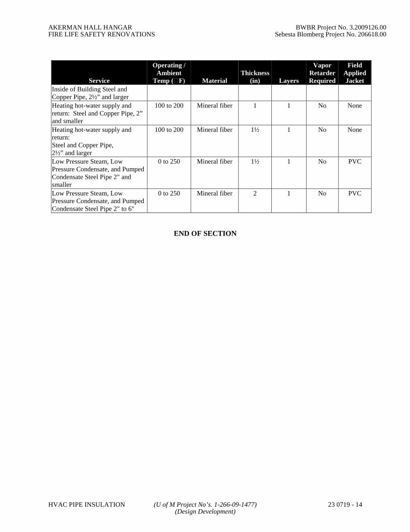
AKERMAN HALL HANGAR BWBR Project No. 3.2009126.00FIRE LIFE SAFETY RENOVATIONS Sebesta Blomberg Project No. 206618.00
HVAC PIPE INSULATION (U of M Project No’s. 1-266-09-1477) 23 0719 - 14(Design Development)
Service
Operating /Ambient
Temp (F) MaterialThickness
(in) Layers
VaporRetarderRequired
FieldAppliedJacket
Inside of Building Steel andCopper Pipe, 2½” and larger
Heating hot-water supply andreturn: Steel and Copper Pipe, 2”and smaller
100 to 200 Mineral fiber 1 1 No None
Heating hot-water supply andreturn:Steel and Copper Pipe,2½” and larger
100 to 200 Mineral fiber 1½ 1 No None
Low Pressure Steam, LowPressure Condensate, and PumpedCondensate Steel Pipe 2" andsmaller
0 to 250 Mineral fiber 1½ 1 No PVC
Low Pressure Steam, LowPressure Condensate, and PumpedCondensate Steel Pipe 2" to 6"
0 to 250 Mineral fiber 2 1 No PVC
END OF SECTION
AKERMAN HALL HANGAR BWBR Project No. 3.2009126.00FIRE LIFE SAFETY RENOVATIONS Sebesta Blomberg Project No. 206618.00
INSTRUMENTATION (U of M Project No’s. 1-266-09-1477) 23 0900 - 1AND CONTROL FOR HVAC (Design Development)
SECTION 23 0900
HVAC INSTRUMENTATION AND CONTROLS
PART 1 - GENERAL
1.1 SUMMARY
A. This Section includes control equipment for HVAC systems and components, includingcontrol components for terminal heating and cooling units not supplied with factory-wired controls.
B. Sequences of operation and system schematics are included on the drawings. Thissection is to be referenced in conjunction with the sequences shown on the drawings.
1.2 GENERAL
A. Provide all labor, materials, equipment, installation, service and training necessary for acomplete, operational, and fully commissioned direct digital control (DDC) system forthe facilities identified on the contract drawings. The system shall use the BACnetprotocol at the TCP/IP level of the architecture.
B. Provide all labor, materials, equipment, service, and training necessary to integrate thenew DDC systems into the existing University DDC network. The communicationsprotocol used by the University is BACnet/IP.
C. Control systems shall be installed by experienced personnel regularly engaged in suchinstallations and in the full employ of the manufacturer or in the employ of a franchisedlicensee of the manufacturer.
D. The controls contractor shall include minor items, which are obviously and reasonablynecessary to complete the installation and usually included in similar work even thoughnot specifically mentioned in the Contract Documents.
E. Temperature control panels and/or enclosures in equipment rooms shall be located atreadily accessible walkup locations approved by the University’s Owner Representative.
F. Building Systems Automation Center (BSAC)
1. The University owns and operates BSAC, which provides central monitoring ofHVAC systems, fire and life safety systems, and other building systems on theTwin Cities campus. Each addition and/or alteration to a building control systemshall be designed to work with the BSAC systems. BSAC uses the MultiLiantworkstation (MLWS) as the primary DDC alarm monitoring device.
2. BSAC is presently located in the Donhowe Building on the East Bank Campus.
G. University DDC Network
1. The University owns and operates a dedicated mixed-mode network (fiber andcopper) for building-to-building and building-to-BSAC communications. EnergyManagement is responsible for network design and network device maintenance.The DDC network is a private LAN with no Internet connections.

AKERMAN HALL HANGAR BWBR Project No. 3.2009126.00FIRE LIFE SAFETY RENOVATIONS Sebesta Blomberg Project No. 206618.00
INSTRUMENTATION (U of M Project No’s. 1-266-09-1477) 23 0900 - 2AND CONTROL FOR HVAC (Design Development)
2. The University DDC system uses Distributed Process Architecture to monitor,control and integrate pneumatic, electric, and DDC systems. The controlscontractor shall consider the DDC network an existing University utility systemto which the specific building control system will be connected.
3. All building level devices must communicate using BACnet/IP and must supportthe objects and services listed in this specification. The University of Minnesotais committed to integration so that point status and automatic control can bechanneled into a common protocol. The University has established BACnet asthe common protocol.
H. University DDC System Functions
1. The general categories of the automated capabilities of the University DDCsystem are:
a. Monitoring and Scheduling: Includes starting, stopping, observing, andreporting the operating status of the equipment, systems, andsubsystems.
b. Intervention: The ability to automatically or manually shift to analternate operating mode when weather or other conditions warrant itfrom a remote location.
c. Integration: The ability to coordinate the operation of several systemswithin a building, or several subsystems within a system, to ensure mostefficient operation.
d. Management Information: The ability to provide cumulative operatingdata such as system run time, units of energy consumed, and preventivemaintenance schedules.
2. All vendor DDC systems must be capable of functioning in the following modes:
a. All life safety and building systems points can be monitored andcommanded, including equipment scheduling, by the MLWS and thevendor workstation 24 Hrs/Day, 7 Days/Wk.
b. System alarms shall be displayed and acknowledged at the vendor’sworkstation, and MLWS 24 Hrs/Day, 7 Days/Wk.
3. University personnel can make control set point, alarm limit and time scheduleprogram modifications from the vendor’s workstation or through any third partyBACnet workstation.
I. BACnet Integration:
1. Due to the complexity and size of the University BACnet system, integrationrequires stringent cooperation between the Energy Management department andthe selected temperature Controls contractor. The University requires directcommunication with the manufacturer's highest level of customer support, andmay need to converse with the manufacturer's BACnet development team duringproject design, implementation, commissioning, and warranty phases.
2. The University of Minnesota is committed to integrating differentmanufacturer’s temperature control systems on a common LAN using a masterworkstation for all existing and future temperature control systems that may beinstalled. U of M BACnet required conformance is limited to B-Side or BACnet

AKERMAN HALL HANGAR BWBR Project No. 3.2009126.00FIRE LIFE SAFETY RENOVATIONS Sebesta Blomberg Project No. 206618.00
INSTRUMENTATION (U of M Project No’s. 1-266-09-1477) 23 0900 - 3AND CONTROL FOR HVAC (Design Development)
building controllers, only. The temperature Controls contractor must providelabor, software, materials, wiring, fiber coordination and expertise to installBACnet Building Controller.
3. Bidding Controls contractor must indicate Readable, Writable or Not Supportedunder Proposed Temperature Control Panel Conformance column in AppendixA for all standard objects shown and return this information with their proposal.
4. BACnet communication shall be via the private DDC LAN directly from thebuilding level controllers without having to route or convert it from a proprietarysource. When building level network controllers are used for core BACnetcommunications, the field level panels on its sub LAN, such as VAVs andunitary level controllers, can utilize BACnet MS/TP, or LON. Building levelnetwork controllers shall be required to support the requirements of Appendix A.
5. BACnet conformance disputes that may arise in the temperature controlcontractors installed BACnet Building Controller will be resolved by U of Mengineers working directly with the temperature Controls contractor’s factory.Cost of translation between non-English speaking testers, developers andcustomer support personal whether overseas or in the USA will be theresponsibility of the controls contractor. On site device testing will be conductedusing the BACnet Manufacturers Association / BACnet Testing Laboratories(BMA/BTL) Virtual Test Shell 3.5.0 (VTS) program. Virtual Test Shell (VTS)is an application for testing the BACnet functionality of various devices used inbuilding automation systems. It is available athttp://sourceforge.net/projects/vts/. Conformance issue fault will be agreed onand resolved using ANSI/ASHRAE Standards 135-2004 publication.
1.3 RELATED SECTIONS
A. None.
1.4 RELATED DOCUMENTS
A. University of Minnesota Construction Standards. Note that this document supersedessection 15950 of the 2002 Construction Standards.
1.5 DEFINITION OF TERMS/ACRONYMS/ABBREVIATIONS
A. Additional definitions of terms or acronyms are included on the contract drawings and inother sections of this specification.
B. In the preparation of submittals and reports, the contractor shall use these definitions andabbreviations. Any terms or abbreviations used by the contractor in submittals andreports that have not been defined in this section shall be defined by the contractor in thefirst section of the submittal or report prior to their use.
C. The following definitions serve as a guide for industry acronyms in the coming sections:
1. ANSI - American National Standards Institute
2. ASHRAE - American Society of Heating Refrigeration and Air ConditioningEngineers
3. BACnet - Building Automation and Controls Network
4. BAC/IP – BACnet communications protocol via IP

AKERMAN HALL HANGAR BWBR Project No. 3.2009126.00FIRE LIFE SAFETY RENOVATIONS Sebesta Blomberg Project No. 206618.00
INSTRUMENTATION (U of M Project No’s. 1-266-09-1477) 23 0900 - 4AND CONTROL FOR HVAC (Design Development)
5. BACnet/MSTP – BACnet communications using master/slave token passing ona field bus.
6. BIBBs - BACnet Interoperability Building Blocks
7. BMA – BACnet Manufacturers Association
8. BTL – BACnet Testing Laboratories
9. CSV – Comma Separated Value
10. DDC - Direct Digital Controls
11. EIA - Electronic Industries Association
12. Field Bus – Communications link between unit level controllers (RS485 orLON)
13. IP – Internet Protocol
14. ISO - International Standards Organization
15. LAN - Local Area Network
16. LON – LONTalk communications protocol
17. LONTalk - Open, published protocol
18. LONWorks - A set of tools and components
19. NIST - National Institute of Standards and Technology
20. PIC - Protocol Implementation Conformance Statement
21. Point Expansion Modules – Devices that are connected to unit controllers viadedicated communication links that are intended to increase the physical pointcount for the unit controller.
22. VAV - Variable Air Volume
1.6 REFERENCES
A. The publications listed below form a part of this specification to the extent referenced.The publications are referred to within the text by the basic designation only.
1. AIR MOVEMENT AND CONTROL ASSOCIATION (AMCA)
2. AMERICAN NATIONAL STANDARDS INSTITUTE (ANSI)
3. AMERICAN SOCIETY OF HEATING, REFRIGERATION AND AIR-CONDITIONING ENGINEERS (ASHRAE)
a. ASHRAE 135-2004 BACnet Standard
4. FEDERAL COMMUNICATIONS COMMISSION (FCC)
5. INSTITUTE OF ELECTRICAL AND ELECTRONICS ENGINEERS (IEEE)
6. INTERNATIONAL ORGANIZATION FOR STANDARDIZATION (ISO)
7. NATIONAL ELECTRICAL MANUFACTURERS ASSOCIATION (NEMA)
8. NATIONAL FIRE PROTECTION ASSOCIATION (NFPA)
9. UNDERWRITERS’ LABORATORIES (UL)
a. UL 864

AKERMAN HALL HANGAR BWBR Project No. 3.2009126.00FIRE LIFE SAFETY RENOVATIONS Sebesta Blomberg Project No. 206618.00
INSTRUMENTATION (U of M Project No’s. 1-266-09-1477) 23 0900 - 5AND CONTROL FOR HVAC (Design Development)
1.7 PRODUCTS FURNISHED, BUT NOT INSTALLED UNDER THIS SECTION
A. Water-side pressure sensors. U of M will install required pressure sensors in existingpiping. Controls contractor is responsible for all wiring, checkout, and commissioning ofwater-side pressure devices.
1.8 PRODUCTS INSTALLED, BUT NOT FURNISHED UNDER THIS SECTION
A. None
1.9 PRODUCTS INTEGRATED WITH THE WORK OF THIS SECTION
A. None
1.10 PROJECT DESCRIPTION
A. The work covered by this specification and related sections consists of providing allplans, equipment, labor, materials, detailed control drawings of each piece of equipment,engineering, technicians and supervision as required to replace the existing HoneywellDDC controls (XL Plus) in building 165 (EECS). See the as-built control systemdrawings for details. A dedicated fiber communication trunk or dedicated copper cablewill be used for network communication between the new network controllers and theexisting campus DDC network. The work consists of, but is not limited to, the following:
1. Replace the existing DDC controls.
2. Furnish and install communications equipment necessary for the new controlsystem to effectively transmit and receive data between building 165 and theexisting campus DDC network.
3. Outside air temperature shall be mapped globally to each controller. Provide asingle outside air sensor for use by the building controllers. All global pointsmust have an internal default value in every panel in case communication isdisrupted to the main controller.
4. Furnish and install all necessary hardware to monitor and control identifiedpoints as shown in the project drawings and points list(s).
5. Furnish and install new enclosures for all new DDC panels, network equipment,and interfaces systems unless the Owner grants permission to reuse the existingDDC enclosures.
6. Furnish and install A/C current sensors for monitoring status of constant speedfans and pumps. Status of motors controlled by VFDs shall be sensed by flow orpressure switches or as a binary input from the drive. Where common statussensors (flow or pressure) are present on alternating pump systems (i.e. lead/lag),remove and install A/C current sensors to monitor the lead and all lag pumps.
7. The controls contractor is not responsible for installing new wells and wellsensors shown in the system drawings or point lists.
8. The controls contractor is shall furnish but not install new pressure transducersrequired for all Steam, Hot Water, Chilled Water, and other non-airside systempressures. The specifications for the transducers are: Output Signal: 0.1 –10Vdc/4-20mA (3-Wire) or 4-20mA (2-Wire); Supply Voltage - 10-36Vdcunregulated. The controls contractor shall furnish and install all required air-side pressure transducers.

AKERMAN HALL HANGAR BWBR Project No. 3.2009126.00FIRE LIFE SAFETY RENOVATIONS Sebesta Blomberg Project No. 206618.00
INSTRUMENTATION (U of M Project No’s. 1-266-09-1477) 23 0900 - 6AND CONTROL FOR HVAC (Design Development)
9. Locate enclosures/controllers only at locations pre-approved by the University’sOwner’s Representative.
10. Reuse existing cable and conduit when possible. Where applicable install newconduit and cable. Follow all electrical code requirements.
11. Remove and properly dispose of all existing duct well, and pressure differentialsensors, flow switches, wiring, enclosures, relays, miscellaneous parts, etc.
12. Return all existing Honeywell DDC controllers to the Owner.
13. Furnish, install and program all software necessary to implement a complete andoperational system, including entry and verification of all data files, pointmapping, graphics and trees.
14. Provide submittal documents, shop drawings, detailed equipment drawings foreach piece of equipment with sequence of operations and specifications,construction documents, complete operating and maintenance manuals.
15. Accomplish commissioning and acceptance tests as indicated and provide acommissioning document of all systems.
16. Provide field service and warranty work as specified.
17. All NFPA references are per 2002 Edition.
18. Controls contractor is responsible for field verification of all equipmentlocations before the start of construction. All sensing elements (except for pipewells, well sensors, hydronic pressure transducers) shall be installed, calibrated,and tested by the controls contractor.
19. All network connections and upgrades shall be performed in an acceptablemanner to the University’s Owner’s Representative. Prior to connecting to thecampus network the controls contractor shall contact the University’s Owner’sRepresentative.
1.11 SUBMITTALS
A. Upon receipt of order, the controls contractor will submit drawings for approval prior toordering or installing any equipment.
B. Copies of all required software shall be submitted to the Owner prior to the start ofconstruction. No pay applications will be approved until all required software has beenreceived.
C. A work schedule (implementation plan) shall be presented to the Owner before the startof work.
1. All work shall be scheduled with the Owner to minimize building interruptions.
2. Any service interruptions for making connections to the existing system shall bescheduled well in advance with the Owner and only during periods approved bythe Owner.
3. The schedule shall include a timeline for hardware changes, softwareprogramming, communication connections, training, projected completion dates,etc.
D. If a conflict, error, omission or lack of detailed description is discovered in the ContractDocuments, the controls contractor shall immediately notify the Owner and request
AKERMAN HALL HANGAR BWBR Project No. 3.2009126.00FIRE LIFE SAFETY RENOVATIONS Sebesta Blomberg Project No. 206618.00
INSTRUMENTATION (U of M Project No’s. 1-266-09-1477) 23 0900 - 7AND CONTROL FOR HVAC (Design Development)
clarification. The Owner will resolve the conflict and make any corrections orinterpretations necessary to fulfill the intent of the plans and specifications.
E. Shop drawings shall be 11 inch by 17 inch, landscape, bound on the left edge. Theyshall be produced with Microsoft Visio or Autodesk AutoCAD software. Organize thepackages by building. All documents shall be submitted electronically in portabledocument format (PDF). At the request of the Owner, shop drawings will also besubmitted in the native CAD format.
F. All text based documents and product data sheets shall be 8 ½ inch by 11 inch formatbound on the left edge. All documents shall be submitted electronically in portabledocument format (PDF).
G. Software files shall be submitted on fully labeled CDs that shall include a table ofcontents file in PDF format that provides a description of all of the files on the CD.
H. Submittals Prior To Construction
1. Shop Drawings
a. System Architecture Design Diagram
(1) A riser diagram that shall show the IP layer and all of the fieldbus layers.
(2) It shall show each computer, printer, router, repeater, controller,and protocol translator that is connected to either the IP layer orany of the field busses.
(3) Where applicable, this diagram shall include the existing controlsystem that is to be integrated into the new system.
(4) Each component that is shown shall have a name that isrepresentative of how it will be identified in the completeddatabase and the manufacturer’s name and model number.
(5) The physical relationship of one component to anothercomponent shall reflect the proposed installation.
(6) This diagram shall not include power supplies, sensors or enddevices.
b. Layout Design Drawing for each control panel:
(1) The layout drawing shall be to scale with all devices shown intheir proposed positions.
(2) All control devices shall be identified by name.(3) All terminal strips and wire channels shall be shown.(4) All control transformers shall be shown.(5) All 120 VAC receptacles shall be shown.(6) All IP connection points shall be shown.
c. Wiring Design Diagram for each control panel.
(1) The control voltage wiring diagram shall clearly designatedevices powered by each control transformer. The diagram shallclearly show the consistent grounding of the appropriate powerconnection. All wire identification numbers shall be annotatedon the diagram.
(2) The Field Bus wiring diagram shall clearly show the use of thedaisy chain wiring concept, the order in which the devices areconnected to the Field Bus, and the location of end of segment

AKERMAN HALL HANGAR BWBR Project No. 3.2009126.00FIRE LIFE SAFETY RENOVATIONS Sebesta Blomberg Project No. 206618.00
INSTRUMENTATION (U of M Project No’s. 1-266-09-1477) 23 0900 - 8AND CONTROL FOR HVAC (Design Development)
termination devices. All wire identification numbers shall beannotated on the diagram.
(3) If shielded communication wiring is used, the grounding of theshield shall be shown.
(4) The terminal strip wiring diagram shall identify all connectionson both sides of the terminal strip. Wiring label numbers for allwiring leaving the control panel shall be annotated on thediagram.
(5) Where pneumatic devices are monitored or controlled by theDDC systems, the control panel wiring diagrams shall includepneumatic piping diagrams for all components.
d. Wiring Design Diagram for individual components (controllers, protocoltranslators, etc.): The wiring diagram for each component shall identifyall I/O, power, and communication wiring and the locations on theterminal blocks to which the wires are landed.
e. Installation Design Detail for each I/O device.
(1) A drawing of the wiring details for each sensor and/or enddevice.
(2) For devices with multiple quantities, a standard detail may besubmitted.
f. A System Flow Design Diagram for each controlled system.
(1) A two dimensional cross sectional diagram showing keycomponents such as fans, coils, dampers, valves, pump, etc.
(2) Identify the locations and names of all sensors and end devicesthat are associated with the control system. Label the panelname and terminal numbers where the connections are landed.
(3) A legend shall be provided for all symbols used.
2. Data
a. BACnet Compliance Documentation:
(1) BACnet Interoperability Building Blocks (BIBBs) and PICsStatement: The Contractor will submit up-to-date PICS andBIBBs Statements for each controller and workstation showingANSI/ASHRA 135-2004 BACnet communication protocolstandards that identifies all of the portions of BACnet that thevendor adheres to. The PIC statement must show conformanceto the BACnet devices the vendor proposes to use. SeeAppendix A for additional PIC information. The vendor PICSstatement will contain the following:(a) BACnet protocol revision(b) Applications software and firmware revision(c) Vendor and BACnet object description(d) BIBBs supported by the device(e) The standardized BACnet device profile to which the
device conforms(f) The non-standardized BACnet device application
services(g) A list of all standard and proprietary object types that
are supported
AKERMAN HALL HANGAR BWBR Project No. 3.2009126.00FIRE LIFE SAFETY RENOVATIONS Sebesta Blomberg Project No. 206618.00
INSTRUMENTATION (U of M Project No’s. 1-266-09-1477) 23 0900 - 9AND CONTROL FOR HVAC (Design Development)
(h) For each object type that is supported, the Universityrequires the following:
(1) Optional properties that are supported with the device or BACnet server
(2) A list of properties that can be written using BACnet services
(3) Any object that can be dynamically created or deleted using BACnet services
(4) Any restrictions in the data value range for properties
(i) Data link layer options supported(j) Device address binding (necessary for two-way
communication with MS/TP devices)(k) Networking options (BBMD, MS/TP)(l) Character sets supported(m) Segmented requests or responses supported
b. Direct Digital Control System Hardware Technical Data.
(1) A complete bill of materials of equipment to be used indicatingquantity, manufacturer, and model number.
(2) Manufacturer’s description and technical data for each uniquedevice to include performance curves, product specificationsheets, and installation instructions. When a manufacturer’sdata sheet refers to a series of devices rather than a specificmodel, the data specifically applicable to the project shall behighlighted or clearly indicated by other means.
(3) This requirement applies to:(a) Controllers(b) Transducers/Transmitters(c) Sensors(d) Actuators(e) Valves(f) Relays and Switches(g) Control Panels(h) Power Supplies(i) Batteries(j) Operator Interface Equipment
c. An Instrumentation List for each controlled system.
(1) The list shall be in a table format.(2) Include name, type of device, manufacturer, model number, and
product data sheet number.
d. Sequence of Control: A sequence of control for each system beingcontrolled. Include the following as a minimum.
(1) Process control sequence for each end device.(2) Supervisory logic sequence of control for each system.(3) The impact of each global application program on the sequence
of control (Example: Demand Control).(4) A list of all physical inputs and outputs associated with each
sequence.(5) Within the sequence of control, all application parameters that
are to be user adjustable from an OWS shall be annotated with(adj) after the name of the parameter. This shall include setpoints, reset schedule parameters, calibration offsets, timersettings, control loop parameters such as gain, integral timeconstant, sample rates, differentials, etc.

AKERMAN HALL HANGAR BWBR Project No. 3.2009126.00FIRE LIFE SAFETY RENOVATIONS Sebesta Blomberg Project No. 206618.00
INSTRUMENTATION (U of M Project No’s. 1-266-09-1477) 23 0900 - 10AND CONTROL FOR HVAC (Design Development)
(6) All points that shall be subject to manual control from anoperator workstation.
(7) A list of all alarm points, a description of the alarm and adescription of the alarm criteria.
e. Binding Map
(1) A list of the device-to-device (peer-to-peer) data flow. Thisshall not include the flow of data from devices to the OWS.
(2) Include:(a) Description of the variable.(b) Sending device.(c) Receiving device.
I. Submittals During Construction
1. Training Manuals for each Training Course
a. Submit the following six weeks in advance of the training:
(1) List of training objectives.(2) Outline of the course with time allocations per topic.(3) Training presentation material (slides, word documents, etc.).(4) Copy of training reference material (product manuals to be used,
etc.).(5) Schematic of the training equipment to be used with model
numbers on each component.(6) A description of the measurement devices to measure training
effectiveness (quizzes, programming exercises, course exam).(7) Instructor’s name and resume with an emphasis on experience in
presenting training programs.
2. Startup Testing Plan: Submit a start up testing plan for each unique system.
a. The purpose of a startup test is to demonstrate the completeness of thephysical tasks associated with installation and the performance of thecomponents.
b. For each task on the startup test checklist, the plan shall require thetechnician to enter his or her initials and the date the test was completedalong with any recorded data such as voltages, offsets, or tuningparameters. Any deviations from the submitted installation plan shallalso be recorded.
c. Required elements of the startup testing include:
(1) Measurement of voltage sources, primary and secondary.(2) Verification of proper controller power wiring.(3) Verification of component inventory when compared to the
submittals.(4) Verification of labeling on components and wiring.(5) Verification of connection integrity and quality (loose strands
and tight connections).(6) Verification of bus topology, grounding of shields and
installation of termination devices.(7) Verification of point checkout.
(a) Each I/O device is landed per the submittals andfunctions per the sequence of control.
AKERMAN HALL HANGAR BWBR Project No. 3.2009126.00FIRE LIFE SAFETY RENOVATIONS Sebesta Blomberg Project No. 206618.00
INSTRUMENTATION (U of M Project No’s. 1-266-09-1477) 23 0900 - 11AND CONTROL FOR HVAC (Design Development)
(b) Analog sensors are properly scaled and a value isreported.
(c) Binary sensors have the correct normal position and thestate is correctly reported.
(d) Analog outputs have the correct normal position andmove full stroke when so commanded.
(5) Analog outputs shall be tested to verify that any controlled pneumatic devicestravel full stroke when the AO is varied from 0% to 100% output.
(e) Binary outputs have the correct normal state andrespond appropriately to energize/de-energizecommands.
(8) Documentation of analog sensor calibration (measured value,reported value and calculated offset).
(9) Documentation of Loop tuning (sample rate, gain and integraltime constant).
d. Submit at least two weeks prior to equipment startup.
3. Startup Testing Report.
a. Startup testing reports shall be submitted on a per system basis.
b. Startup testing reports shall be the documented results of the executedstartup testing plans.
4. Graphic Pages: Submit a sample graphic page for each type of page described inthe specification section on graphic pages.
J. Submittals After Construction
1. The following is a list of post construction submittals that shall be updated toreflect any changes during construction and re-submitted as “As-Built”. As-Built drawings will each be stamped “As-Built” and have the as-built date onthem. The As-Built drawings will contain at a minimum:
a. System architecture drawing.
b. Detailed drawings for each piece of controlled and monitored equipment
(1) Layout drawing for each control panel.(2) Wiring diagram for each control panel.(3) Wiring diagram for individual components.(4) Point lists(5) Room Schedules(6) Sequence of operation(7) Hardware with part number information(8) System flow diagram for each controlled system.
c. Detailed routing of all communication trunk wires (building-to-buildingand within building), locations of all network and integration devices,front-end workstations, UPS and campus network/LAN connections.
d. Binding map.
2. Operation and Maintenance Manuals
a. The controls contractor shall provide one electronic (PDF) copy andthree (3) bound copies of Operation and Maintenance Manuals.
b. Deliver manuals to the University project manager.

AKERMAN HALL HANGAR BWBR Project No. 3.2009126.00FIRE LIFE SAFETY RENOVATIONS Sebesta Blomberg Project No. 206618.00
INSTRUMENTATION (U of M Project No’s. 1-266-09-1477) 23 0900 - 12AND CONTROL FOR HVAC (Design Development)
c. Manuals shall be bound in heavy-duty, vinyl-covered, three-post, loose-leaf binders, permanently labeled on front and spine of each binder.
d. Arrange the manuals according to specification section numbers used inthe Project Manual; include a table of contents that identifies theresponsible installing contractor, contact person, and telephone numberwith area code and thumb tab index sheets.
e. Provide pocket folders for folded sheet information.
f. Maintenance and Operating Manual shall include the following type ofinformation:
(1) One copy of the executed Certificate(s) of SubstantialCompletion. This document will be used to communicate to allnecessary University personnel the starting date of the one-yearWarranty period.
(2) Signed record copy of bonds, guarantees, and warrantiesrequired by the Contract Documents.
(3) Manufacturer’s required preventative maintenance inspections,testing, service, lubrication, maintenance instructions, andschedules.
(4) Parts lists and local service organization.(5) As-built wiring and piping diagrams.(6) System architecture diagram for components within the building
annotated with specific location information.(7) As-built drawing for each control panel.(8) As-built wiring design diagram for each control panel.(9) As-built wiring design diagram for all components.(10) Installation design details for each I/O device.(11) As-built system flow diagram for each system.(12) Sequence of control for each system.(13) Room schedules.(14) Binding map for the building.(15) Product data sheet for each component.(16) Installation data sheet for each component.(17) Other information required by the Specifications.
g. The Contractor shall instruct University personnel in the use ofMaintenance and Operating Manuals.
3. Software
a. Submit a copy of all software installed on the servers and workstations.
b. Submit all licensing information for all software installed on the serversand workstations.
c. Submit a copy of all software used to execute the project even if thesoftware was not installed on the servers and workstations.
d. Submit all licensing information for all of the software used to executethe project.
e. All software revisions shall be as installed at the time of the systemacceptance.
4. Firmware Files

AKERMAN HALL HANGAR BWBR Project No. 3.2009126.00FIRE LIFE SAFETY RENOVATIONS Sebesta Blomberg Project No. 206618.00
INSTRUMENTATION (U of M Project No’s. 1-266-09-1477) 23 0900 - 13AND CONTROL FOR HVAC (Design Development)
a. Submit a copy of all firmware files that were downloaded to or pre-installed on any devices installed as part of this project.
b. This does not apply to firmware that is permanently burned on a chip atthe factory and can only be replaced by replacing the chip.
c. Submit a copy of all application files that were created during theexecution of the project.
d. Submit a copy of all graphic page files created during the execution ofthe project.
e. Submit a copy of all secondary graphic files such as bitmaps, jpegs, etc.that were used in the creation of the graphic pages.
K. Project Closeout Submittals:
1. The controls contractor shall advise the Owner throughout the duration ofconstruction as to the status of the contract closeout submittals including, but notlimited to, the ongoing development of the maintenance and operations manualsand record documents.
2. The Contractor shall assemble and submit as one package the following beforemaking application for final payment.
a. Consent of Surety.
b. Documentation that Contractor returned University keys.
c. Documentation that Contractor returned signs reading, “ConstructionStaging Area, Vehicle Permit Required, Violators Will be Tagged andTowed.”
d. Documentation that the Punch list is complete.
e. Executed Certificate of Occupancy (if required).
f. Executed TGB Total Payment Affidavit (if required).
g. Executed TGB Verification of Completed Work Affidavit (if required).
h. Executed Prevailing Wage Payment Affidavit (if required).
i. Evidence of Completed Operations Liability insurance coverage duringthe one-year correction period (if required).
j. Waste manifests, TCLP (Toxicity Characteristic Leachate Procedure),and OSHA monitoring results for asbestos or lead, as required by theContract Documents (if required).
1.12 PROJECT RECORD DOCUMENTS
A. General Requirements:
1. The Contractor shall maintain a set of Contract Documents at the site, on whichvariations shall be accurately marked with red erasable pencil on a daily basis.All changes, whether resulting from change orders, Architect’s supplementaryinstructions, Contractor change directives, or other job noted changes, shall berecorded. The controls contractor shall periodically verify that this is being donesatisfactorily.

AKERMAN HALL HANGAR BWBR Project No. 3.2009126.00FIRE LIFE SAFETY RENOVATIONS Sebesta Blomberg Project No. 206618.00
INSTRUMENTATION (U of M Project No’s. 1-266-09-1477) 23 0900 - 14AND CONTROL FOR HVAC (Design Development)
B. Contract Drawings
1. Maintain a clean, undamaged set of blue or black line prints of ContractDrawings to use as the Project record documents.
2. Mark the drawing sets to show the actual installation where the installationvaries substantially from the work as originally shown.
3. Give particular attention to recording concealed elements that will be difficult tomeasure and record at a later date. Also record new information that is importantto the Owner but is not shown on Contract Drawings.
4. Note the related change order number where applicable.
5. Organize the record drawing sheets into manageable sets. Bind sets with durable-paper cover sheets; print the University Project Number and Name, and drawingnumbers and titles on the cover sheet.
C. Record Project Manual
1. Maintain a clean, undamaged, complete set of the Project Manual to use as theProject record documents.
2. Include one copy of the addenda and other written documents issued during theconstruction period (Change Orders, RFIs, PRs, etc.) with the record ProjectManual.
3. Contractor shall submit the Project record documents to the University for finalinspection and comment at the completion of the job.
4. The final payment will not be made to the Contractor until the record documentsand the Maintenance and Operating Manuals are received and approved inwriting by the University.
5. Two months before expiration of the one-year correction period the controlscontractor shall conduct a walk through and provide a written summary offindings and recommendations.
6. Submit electronic versions of all CAD drawings, points lists, and operatingsequences. The electronic copies shall be stored on CDs and shall be saved in aneditable format. Acceptable formats include Microsoft Office program formats(i.e. Word, Excel, Access, etc.), Visio, and AutoCAD. Other formats must beapproved by the University at time of project award.
1.13 WARRANTY
A. Warrant all work as follows:
1. The warranty period for labor and material for the control system, including allsubcontractor work, shall be 12 months after acceptance by Owner. TheOwner’s written acceptance will be given after verification testing demonstratesthat the equipment is operating in accord with the contract documents. Minordeficiencies identified during testing that do not affect the functionalperformance of the equipment will not be used to deny acceptance for thepurposes of determining the start of the warranty period.
2. During the warranty period, the Contractor shall respond to the Owner’s requestfor warranty service within 24 hours during normal business hours.

AKERMAN HALL HANGAR BWBR Project No. 3.2009126.00FIRE LIFE SAFETY RENOVATIONS Sebesta Blomberg Project No. 206618.00
INSTRUMENTATION (U of M Project No’s. 1-266-09-1477) 23 0900 - 15AND CONTROL FOR HVAC (Design Development)
3. For systems designated at critical, the Contractor shall respond to warrantyservice requests within 4 hours.
4. The Contractor shall correct all warranty repairs at no cost to the Owner.
5. The Contractor shall make all reasonable efforts to minimize the Owner’sbusiness disruption and loss associated with warranty repairs. This includesexpedited shipping of materials, overtime work, night/weekend work, etc.
6. Software upgrades and service patches shall be made available and installed bythe Contractor at no cost to the University during the warranty period.
7. The Contractor shall maintain a copy of the project database through thewarranty period.
1.14 OWNERSHIP OF PROPRIETARY MATERIAL
A. The Owner shall retain all rights to software for this project.
B. The Owner shall sign a copy of the manufacturer’s standard software and firmwarelicensing agreement as a condition of this contract. Such license shall grant use of allprograms and application software to the Owner as defined by the manufacturer’s licenseagreement, but shall protect the manufacturer’s rights to disclosure of Trade Secretscontained within such software.
C. The licensing agreement shall not preclude the use of the software by individuals undercontract to the owner for commissioning, servicing, or altering the system in the future.Use of the software by individuals under contract to the owner shall be restricted to useon the owner’s computers and only for the purpose of commissioning, servicing, oraltering the installed system.
D. All project developed software, files and documentation shall become the property of theOwner. These include but are not limited to:
1. Server and Workstation software
2. Application Programming Tools
3. Configuration Tools
4. Addressing Tools
5. Application Files
6. Configuration Files
7. Graphic Files
8. Report Files
9. Graphic Symbol Libraries
10. All Documentation.
PART 2 - PRODUCTS
2.1 MANUFACTURERS
A. Approved Manufacturers
1. Johnson Controls

AKERMAN HALL HANGAR BWBR Project No. 3.2009126.00FIRE LIFE SAFETY RENOVATIONS Sebesta Blomberg Project No. 206618.00
INSTRUMENTATION (U of M Project No’s. 1-266-09-1477) 23 0900 - 16AND CONTROL FOR HVAC (Design Development)
2. Siemens
3. Trane
4. University Approved Alternate
B. Air flow/temperature measurement stations
1. Ebtron
2. TekAir model Vortek
3. Air Monitor VoluProbe
C. Acceptable Installation Contractors
1. Branch offices and independent representatives for the above manufacturersmust have a full staff of project managers, project engineers, system applicationengineers, application engineers and technicians. Branch offices and independentrepresentatives must have a separate fully staffed service department to be anacceptable bidder.
2. Approved Installation Contractors
a. Johnson Controls Branch Office – Minneapolis
b. Siemens Building Technologies Branch Office – Minneapolis
c. Trane Branch Office – Minneapolis
3. Installation contractors not currently on the approved list may be considered ifthey meet the requirements of this specification. Financial stability and priorexperience on University (or similar) projects will be considered by the Ownerwhen selecting an installation contractor.
2.2 SYSTEM ARCHITECTURE
A. The DDC system architecture shall consist of two layers, the TCP/IP layer and the fieldbus layer.
B. The TCP/IP layer connects all of the buildings on a single dedicated and isolatednetwork. Fixed IP addresses for connections to the University private DDC networkshall be used for each device.
C. BACnet Building Controllers (B-BC) shall be used to connect each field bus to theTCP/IP layer.
2.3 NETWORKING
A. IP Network: All devices that connect to the WAN shall be capable of operating at 100megabits per second.
B. IP-to-Field Bus Routing Devices
1. BACnet Building Controller shall be used to provide this functionality.
2. These devices shall be configurable locally with RS232 or IP crossover cableand configurable via the IP network.
3. The routing configuration shall be such that only data packets from the field busdevices that need to travel over the IP level of the architecture are forwarded.
AKERMAN HALL HANGAR BWBR Project No. 3.2009126.00FIRE LIFE SAFETY RENOVATIONS Sebesta Blomberg Project No. 206618.00
INSTRUMENTATION (U of M Project No’s. 1-266-09-1477) 23 0900 - 17AND CONTROL FOR HVAC (Design Development)
C. Field Bus
1. The wiring of components shall use a bus or daisy chain concept with no tees,stubs, or free topology.
D. Repeaters
1. Where repeaters are required to connect two segments, repeaters shall beinstalled in an enclosure mounted in an accessible area.
2.4 BUILDING LEVEL CONTROLLERS (B-BC)
A. Building level DDC controllers shall be microprocessor-based, multi-tasking, multi-user,real-time digital control processors fully capable of being integrated with the selectedvendor’s master work station, or any third party BACnet workstation.
B. Building level DDC controllers shall utilize BACnet open standard communicationprotocol. All building level controllers shall communicate using BACnet/IP.
C. A BACnet Building Controller (B-BC) as defined by ASHRAE Annex L is a generalpurpose, field programmable device capable of carrying out a variety of buildingautomation and control tasks. It enables the specification of the following:
1. Data Sharing
a. Ability to provide the values of any of its BACnet objects
b. Ability to retrieve the values of BACnet objects from other devices
c. Ability to allow modifications such as scheduling and present value ofsome or all of its BACnet objects by another device as shown in U of Mrequired object table (see Appendix A).
2. Alarm and Event Management
a. Generation of alarms / events notifications and the ability to direct themto recipients using the BACnet intrinsic alarming method
b. Maintain a list of unacknowledged alarms / events retrievable usingstandard BACnet Services
c. Maintain a list of alarms / events retrievable using standard BACnetServices
d. Notifying other recipients that the acknowledgment has been received
e. Adjustment of alarm / event parameters
3. Scheduling
a. Ability to schedule output actions, both in the local device and in otherdevices, both binary and analog, based on date and time
4. Trending
a. Collection and delivery of (time, value) pairs
5. Device and Network Management
a. Ability to respond to information about its status
b. Ability to respond to requests for information about any of its objects

AKERMAN HALL HANGAR BWBR Project No. 3.2009126.00FIRE LIFE SAFETY RENOVATIONS Sebesta Blomberg Project No. 206618.00
INSTRUMENTATION (U of M Project No’s. 1-266-09-1477) 23 0900 - 18AND CONTROL FOR HVAC (Design Development)
c. Ability to respond to communication control messages
d. Ability to synchronize its internal clock upon request. (not required by Uof M)
e. Ability to perform re-initialize upon request (not required by U of M)
f. Ability to upload its configuration and allow it to be subsequentlyrestored
g. Ability to command half routers to establish and terminate connections(not required by U of M)
D. If Building Controllers have embedded I/O, all of the requirements for I/O that aredescribed under Unit Level Controllers shall apply.
E. The temperature controls contractor's B-BC device(s) shall support all ANSI/ASHRAE135-2004 standard object required and optional properties as listed in Appendix A.BACnet intrinsic alarming is required. All objects and object properties shall besupported so that alarms are sent from the temperature controls contractor's BACnetdevice without having to be solicited from the University BACnet Operators Workstation(BOWS) or U of M Master History PC.
F. DDC panels and devices must utilize ANSI/ASHRAE 135-2004 BACnetCommunications Protocol on a single building level network. BACnet communicationsmust not cause derogated communications on the sites existing temperature controlnetwork. Derogation includes router, switch, or hub lockups, BACnet building controllerlockups, excessive site network slowdowns, unnecessary and repeated ‘who is’messages. Refer to ASHRAE BACnet standard for definition of unnecessary Who-ismessages.
G. U of M BACnet Required Protocol Services supported:
1. Acknowledge Alarm
2. Confirmed Event Notify
3. Get Alarm Summary
4. Get Enrollment Sum
5. Add List Element (for the purpose of allowing the addition of a recipient to theBB-C)
6. Remove List Element (for the purpose of allowing the deletion of a recipient tothe BB-C)
7. Read Property
8. Read Property Multiple
9. Write Property
10. Write Property Multiple
11. Confirm Private Xfer
12. I AM
13. I Have
14. Unconfirmed COV Notify

AKERMAN HALL HANGAR BWBR Project No. 3.2009126.00FIRE LIFE SAFETY RENOVATIONS Sebesta Blomberg Project No. 206618.00
INSTRUMENTATION (U of M Project No’s. 1-266-09-1477) 23 0900 - 19AND CONTROL FOR HVAC (Design Development)
15. Unconfirmed Event Notify
16. Time Synchronization
17. Who Has
18. Who Is
19. UTC Time Sync
20. Get Event Info
H. All building controllers must be capable of having their databases uploaded, downloadedand viewed from the vendor’s master workstation.
I. All building level controllers shall have a local port that can connect to a laptop PC orother hand-held tool for local service work, troubleshooting, etc. Each controller shallinclude the capability to store, retrieve and print alarm summaries, trends and othercritical point summaries or reports.
J. Memory: Each DDC controller shall have sufficient memory to support its ownoperating system and databases and continuous trending on all analog points for thatcontroller (AV, AI, AO) based on 300 sample intervals.
K. Integrated On-line Diagnostics: Each DDC controller shall continuously perform self-diagnostics and communication diagnosis of all associated unit level equipment. TheDDC controller shall provide both local and remote annunciation of any detectedcomponent failures, or repeated failure to establish communication. Indication of thediagnostic results shall be provided at each DDC controller and shall not require theconnection of an auxiliary I/O device.
L. Power Fail Restart: In the event of the loss of normal power, there shall be an orderlyshutdown of all DDC controllers to prevent the loss of database or operating systemsoftware. Non-volatile memory shall be incorporated for all critical controllerconfiguration data, and battery back up shall be provided to support the real-time clockand all volatile memory for a minimum of seventy-two (72) hours. Upon restoration ofnormal power, the DDC controller shall automatically resume full operation withoutmanual intervention. Should a DDC controller memory be lost for any reason, the usershall have the capability of reloading the DDC controller via the local area network orvia the local interface port.
M. System architectural design shall eliminate dependence upon any single device, front-endor higher level of controller for alarm reporting and control execution. Each DDCcontroller shall operate independently by performing its own specified control, alarmmanagement, operator I/O, and historical data collection. The failure of any singlecomponent or network connection shall not interrupt the execution of control strategiesat other operational devices.
N. Building level DDC controllers shall be able to access any data from, or send controlcommands and alarm reports directly to any other building level controller orcombination of controllers on the IP network without dependence upon a centralprocessing device. Building level DDC controllers shall also be able to send alarmreports to multiple operator workstations without dependence upon a central processingdevice.
O. All Ethernet network communications will use 100 MPS communication rates.

AKERMAN HALL HANGAR BWBR Project No. 3.2009126.00FIRE LIFE SAFETY RENOVATIONS Sebesta Blomberg Project No. 206618.00
INSTRUMENTATION (U of M Project No’s. 1-266-09-1477) 23 0900 - 20AND CONTROL FOR HVAC (Design Development)
2.5 UNIT LEVEL CONTROLLERS
A. Each Unit Level DDC controller shall consist of modular hardware with plug-in enclosedprocessors, communication controllers, power supplies, input and output (DI, DO, AI,AO) capabilities. A sufficient number of controllers shall be supplied to fully meet therequirements of this specification, the project drawings, and the point lists.
B. Unit level DDC controllers shall utilize BACnet/MSTP or LON open standardcommunication protocol.
C. All unit level controllers, including VAV controllers, must be able to have theirdatabases uploaded, downloaded and viewed from the vendor’s master workstation.
D. Power Fail Restart: In the event of the loss of normal power, there shall be an orderlyshutdown of all DDC controllers to prevent the loss of database or operating systemsoftware. Non-volatile memory shall be incorporated for all critical controllerconfiguration data, and battery back up shall be provided to support the real-time clockand all volatile memory for a minimum of seventy-two (72) hours. Upon restoration ofnormal power, the DDC controller shall automatically resume full operation withoutmanual intervention. Should a DDC controller memory be lost for any reason, the usershall have the capability of reloading the DDC controller via the local area network orvia the local interface port.
E. Each controller will be programmed such that each controlled device will have a defaultvalue in which to be commanded to in the event of a control sensor failure. Theacceptable default values are, last command, full open, or full closed.
F. Controller I/O Requirements
1. Analog Input Circuits
a. The resolution of the A/D chip shall not be greater than 0.01 Volts perincrement. For an A/D converter that has a measurement range of 0 to10 VDC and is 10 bit, the resolution is 10/1024 or 0.00976 Volts perincrement.
b. For non-flow sensors, the control logic shall support a calibration offsetsuch that the raw measured value is added to the (+/-) offset to create acalibration value to be used by the control logic and reported to theOperator Workstation (OWS).
c. For flow sensors, the control logic shall provide support for the use of anadjustable gain and an adjustable offset such that a two point calibrationconcept can be executed (both a low range value and a high range valueare adjusted to match values determined by a calibration instrument).
d. For non-linear sensors such as thermistors and flow sensors thecontroller shall provide software support for the linearization of theinput signal.
2. Binary Input Circuits
a. Dry contact sensors shall wire to the controller with two wires.
b. An external power supply in the sensor circuit shall not be required.
3. Pulse Input Circuits
AKERMAN HALL HANGAR BWBR Project No. 3.2009126.00FIRE LIFE SAFETY RENOVATIONS Sebesta Blomberg Project No. 206618.00
INSTRUMENTATION (U of M Project No’s. 1-266-09-1477) 23 0900 - 21AND CONTROL FOR HVAC (Design Development)
a. Pulse input sensors shall wire to the controller with two wires.
b. An external power supply in the sensor circuit shall not be required.
c. The pulse input circuit shall be able to process up to 20 pulses persecond.
4. True Analog Output Circuits
a. The logical commands shall be processed by a digital to analog (D/A)converter chip. The 0% to 100% control signal shall be scalable to thefull output range which shall be either 0 to 10 VDC, 4 to 20 milliamps or0 to 20 milliamps or to ranges within the full output range.
b. The resolution of the D/A chip shall not be less than 0.04 Volts perincrement or 0.08 milliamps per increment.
5. Binary Output Circuits
a. Single pole, single throw or single pole, double throw relays.
b. Voltage sourcing or externally powered triacs with support for up to 30VAC and 0.5 amps at 24 VAC.
6. Program Execution
a. Process control loops shall operate in parallel and not in sequence unlessspecifically required to operate in sequence by the sequence of control.
b. The sample rate for a process control loop shall be adjustable and shallsupport a maximum sample rate of 1 second.
c. The sample rate for process variables shall be adjustable and shallsupport a maximum sample rate of 1 second.
d. The sample rate for algorithm updates shall be adjustable and shallsupport a maximum sample rate of 1 second.
e. The application shall have the ability to determine if a power cycle to thecontroller has occurred and the application programmer shall be able touse the indication of a power cycle to modify the sequence of controllerimmediately following a power cycle.
7. Local Interface: The controller shall support the connection of a portableinterface device such as a laptop computer or vendor specific hand-held device.Via this local interface, an operator shall be able to:
a. Adjust application parameters.
b. Execute manual control of input and output points.
c. View dynamic data.
G. Unit level controllers shall not be dependent upon any other controller (unit or buildinglevel) to maintain safe operation of the controlled equipment.
H. All unit level controllers and/or enclosures shall be clearly labeled with their Nodeaddress. Tag all wiring on the DDC side of the interface panel identifying the associatedpoint.

AKERMAN HALL HANGAR BWBR Project No. 3.2009126.00FIRE LIFE SAFETY RENOVATIONS Sebesta Blomberg Project No. 206618.00
INSTRUMENTATION (U of M Project No’s. 1-266-09-1477) 23 0900 - 22AND CONTROL FOR HVAC (Design Development)
I. PROHIBITED: Transmitting process variable data via the IP network or field bus foruse in PID control loops. Data transmitted from point expansion modules to unitcontrollers via a dedicated point expansion communication bus is allowed.
J. PROHIBITED: Splitting mechanical systems between more then one Unit Levelcontroller without prior approval from Owner.
2.6 OPERATOR WORKSTATION (OWS)
A. The Operator Interface Workstations will comprise a Personal Computer (PC) togetherwith operator terminals. The PC will be a fully integrated node on the management levelnetwork and shall provide the operator with a graphical interface into the entire network.The monitoring and control functions of the BMCS shall be totally independent of thePC such that if the PC is not operational there shall be no impact on the building controlsystems except for the reduced operator interface capability at that location.
B. Provide OWS at the following locations:
1. Location TBD.
C. Provide OWS meeting, at minimum, the following requirements:
1. Intel motherboard with single Intel Core 2 Duo processor with a minimum speedof 3.0 GHz and 4 MB L2 Cache.
2. 2 Gigabyte of memory.
3. One 160 Gigabyte SATA hard drive.
4. Tower or desktop style case.
5. 4 USB ports.
6. 48x32xCDRW and 16xDVD+/-RW.
7. Auto sensing full duplex 10/100/1000 Ethernet network interface card (NIC).
8. USB style connectors for keyboard and mouse.
9. 256 Megabyte video RAM.
10. All necessary mounting hardware and cables for all components.
11. Integral power supplies which shall be suitably rated for the service.
12. Real time software or hardware clock.
13. 1.44 Floppy disk drive
D. Provide a Video Display Unit (VDU) meeting, at minimum, the following requirements:
1. Flat panel LCD display with screen diagonal measurement of no less than 19inches.
2. Resolution of .28 pitch, 1280 by 1024 pixels with 85Hz minimum refresh rate.
3. Capable of displaying both schematic and alphanumeric data at the same time.
4. 16 million discrete colors.
5. Manufactured by NEC, Viewsonic, Sony, Samsung, or approved equal.

AKERMAN HALL HANGAR BWBR Project No. 3.2009126.00FIRE LIFE SAFETY RENOVATIONS Sebesta Blomberg Project No. 206618.00
INSTRUMENTATION (U of M Project No’s. 1-266-09-1477) 23 0900 - 23AND CONTROL FOR HVAC (Design Development)
2.7 DDC SYSTEM SOFTWARE
A. BACnet Operator Workstations
1. Hardware Communication Function
a. The OWS shall extract data from the hardware environment and movethe data to the data server and/or present the data to the presentationsystem.
b. The OWS shall extract data from the data server and present the data tothe data presentation system.
c. The OWS shall track operator actions at the presentation system andwrite a record of activities to the data server.
2. BACnet Compliance
a. The OWS shall be able to initiate a “Who Is” request to the network.
b. The OWS shall respond to a “Who Is” request from another BACnetdevice with an “I Am” response.
c. The OWS shall be able to read binary and analog data from BACnetdevices that support the reading of data.
d. The OWS shall be able to write binary and analog data to BACnetdevices that support the writing of data from a BACnet OWS.
e. The OWS shall be able to receive alarm messages from BACnet devicesthat export alarm messages.
f. The OWS shall be able to acknowledge alarms from BACnet devices.
g. The OWS shall be able to edit time schedule parameters in BACnetdevices that support the editing of time schedule parameters from aBACnet OWS.
h. The OWS shall be able to retrieve a collection of trend samples from aBACnet device that stores the data and permits the export of that data toa BACnet OWS.
i. The OWS shall be able to initiate time synchronization commands to allBACnet devices that support the receipt of time synchronizationcommands from a BACnet OWS.
3. Data Presentation: Data shall be presented in the following formats.
a. Points lists with dynamic presentation of data. The operator shall beable to create custom point lists with data that originates from multipledevices. A point may be dynamic data from a controller or aconfiguration parameter to be written to a controller by the operator.
b. Graphic pages with dynamic presentation of data on a visual diagramthat represents a building, a floor plan, a cross section of a mechanicalsystem or a table of data.
c. Graphical presentation of historical trend log data plotted against time.
d. Graphical presentation of real time trend data plotted against time.
e. Alarm Presentation

AKERMAN HALL HANGAR BWBR Project No. 3.2009126.00FIRE LIFE SAFETY RENOVATIONS Sebesta Blomberg Project No. 206618.00
INSTRUMENTATION (U of M Project No’s. 1-266-09-1477) 23 0900 - 24AND CONTROL FOR HVAC (Design Development)
(1) Unless restricted by a reduction in viewing authority, anoperator shall be able to view alarms for all systems in a singlealarm list.
(2) Custom alarm views configured for select categories of alarmsshall present only the alarms specified.
(3) Alarm messages shall include identifying information and thesignal value or state at the time of the alarm.
f. Event Presentation
(1) Unless restricted by a reduction in viewing authority, anoperator shall be able to view an event log that chronologicallycaptures all activity created by the system and operator actions.
(2) Custom event views for select categories of events shall presentonly the events specified.
g. Time Schedules
(1) Each time schedule shall have the ability to issue a minimum of10 start and 10 stop commands for the week. The requirementsfor start and stop commands may be different for each day of theweek.
(2) Each time schedule shall also include a holiday componentwhere a holiday is identified by the date and duration (one day,two days, etc.). The time schedule shall support a unique set ofstart and stop commands for each holiday. The time scheduleshall support a minimum of 20 holidays per year. Holidayschedules shall take precedence over standard schedules duringthe holiday period. Holidays that are date specific shall roll overfrom year to year without operator programming action.
(3) There shall be a mechanism to link a master time schedule editorat an OWS to multiple time schedules in various BuildingControllers. Once linked, whenever the master time schedule ischanged at an OWS, the new time schedule parameters shall bedownloaded to all of the linked time schedules. This conceptshall apply to both standard schedules and holiday schedules.
h. The system shall support a configuration that:
(1) Causes the system to go into standby mode (user is logged outbut the current screen is still displayed) after a specific period ofinactivity.
(2) Automatic system logout after a specific period of inactivity.
4. Data Source
a. An operator workstation shall present data from the entire hardwareenvironment.
b. The system architecture shall provide for a minimum of 25 concurrentoperator workstations per system.
5. Operator Access And Privileges
a. There shall be a minimum of four privilege levels.
(1) System Administrator(a) No limitations(b) Only level that can assign or delete users and assign or
modify privileges.

AKERMAN HALL HANGAR BWBR Project No. 3.2009126.00FIRE LIFE SAFETY RENOVATIONS Sebesta Blomberg Project No. 206618.00
INSTRUMENTATION (U of M Project No’s. 1-266-09-1477) 23 0900 - 25AND CONTROL FOR HVAC (Design Development)
(2) Engineer(a) View data in any format.(b) Acknowledge alarms.(c) Inhibit alarms.(d) Exercise control actions.(e) Edit the presentation of data.(f) Modify the system.
(3) Operator(a) View data in any format.(b) Acknowledge alarms.(c) Exercise control actions.
(4) Viewer(a) View data in any format.
b. The level assigned to a specific user shall be the maximum level that canbe used any where in the system. The software shall provide thecapability to reduce a user’s level from his or her maximum level to alower level on a per building or system basis. This may be accomplishedon a per object basis within the database or by the application ofadditional security levels beyond the basic four levels.
c. Signing on to the system shall require a user name and password. Whenthe password is typed in, it shall not be shown on the screen.
d. The software shall provide the capability to establish groups of userswith the same privileges. Once assigned to the group, the user shallautomatically have the maximum privileges and the selectively reducedprivileges assigned to the group.
e. The software shall provide the capability to set user profiles that enableassigning a specific home graphic page, alarm view, and event view.
6. Operator Actions
a. Given the appropriate authority, an operator from an operatorworkstation shall be able to:
(1) View all data that is presented in the forms described previously.(2) Acknowledge alarms.(3) Manually control both physical input and physical output points.(4) Edit both independent and master time schedules.(5) Initiate real time trend logging.(6) Manually initiate reports.(7) Initiate system backups for the database and trend log data.(8) Customize the layout of the operator workstation presentation
which shall then be the default for that user.
b. The operator shall be able to execute the above tasks on data from any ofthe operator workstations.
c. The system shall support the use of Electronic Signature system wide oron a per user basis.
d. All of the operator workstations shall be operable simultaneously.
7. Engineering Actions

AKERMAN HALL HANGAR BWBR Project No. 3.2009126.00FIRE LIFE SAFETY RENOVATIONS Sebesta Blomberg Project No. 206618.00
INSTRUMENTATION (U of M Project No’s. 1-266-09-1477) 23 0900 - 26AND CONTROL FOR HVAC (Design Development)
a. The software shall, as a minimum, enable the following engineeringfunctions from each of the operator workstations:
(1) Create graphic pages for the presentation of dynamic data onvisual images of buildings or equipment.
(2) Create reports for the presentation of historical data in anorganized format.
(3) Create time schedules.(4) Create trend logs in any of the field level devices and assign a
dynamic variable from a field bus device to be trended.(5) Setup long term storage of trend log data on the data server
computer and the automatic transfer of the trend log data to thedata storage tables in the long-term database.
(6) Create alarm objects in any of the field level devices, assign analarm variable from a field bus device to initiate the alarm andset up the alarm routing.
(7) Configure and bring on-line a newly installed BuildingController in support of an initial or incrementally addedbuilding control system.
(8) Configure and bring on-line a newly installed field level devicesin support of an initial or incrementally added building controlsystem.
(9) Create and download applications for programmable devices.(10) Download firmware updates to field level devices.(11) Import all field level devices into the system so that all input
network variables, output network variables and adjustableapplication parameters can be accessed from any of the operatorworkstations.
(12) Establish data flow from one field level device to a second fieldlevel device.
(13) Establish data flow from a field bus device under one IPconnection to a field bus device under a different IP connection.
(14) Configure the system to create backups of the database and allapplication and supporting databases on a scheduled basis.
(15) Setup user groups and individual users and establish authoritylevels for each group and individual user.
(16) Any additional tasks defined later in this document or requiredto deliver a fully functional system.
B. Graphic Page Creation and Editing
1. The Graphics Editor portion of the Engineering Software shall provide thefollowing minimum capabilities:
a. Create and save symbols.
b. Create and save pages.
c. Group and ungroup symbols.
d. Modify an existing symbol.
e. Modify an existing graphic page.
f. Rotate and mirror a symbol.
g. Place a symbol on a page.
AKERMAN HALL HANGAR BWBR Project No. 3.2009126.00FIRE LIFE SAFETY RENOVATIONS Sebesta Blomberg Project No. 206618.00
INSTRUMENTATION (U of M Project No’s. 1-266-09-1477) 23 0900 - 27AND CONTROL FOR HVAC (Design Development)
h. Place analog dynamic data in decimal format on a page.
i. Place binary dynamic data using state descriptors on a page.
j. Create motion through the use off gif, jpeg, bmp or svg files
k. Place test mode indication on a page.
l. Place manual mode indication on a page.
m. Place links using a fixed symbol or flyover on a page.
(1) Links to other graphics.(2) Links to web sites.(3) Links to notes.(4) Links to time schedules.(5) Links to trends.
n. Assign a background color.
o. Assign a foreground color.
p. Place alarm indicators on a page.
q. Change a symbol color as a function of an analog variable.
r. Change a symbol color as a function of a binary state.
s. Change symbols as a function of a binary state.
t. All symbols used by the contractor in the creation of graphic pages shallbe saved to a library file for use by the owner.
C. Event Logging
1. The system shall maintain a log of all operator activity, system messages, alarms,and alarm acknowledgments.
2. Operator activity is defined as any action by an operator such as changing thevalue of an application parameter, modifying a program, acknowledging analarm, logging on, logging off, etc. Any change in the system caused by operatoraction shall be part of the log. The log shall include the event, the time of theevent, the part of the system affected, and an identification of the operator andthe OWS from which the change was made.
3. When the event deals with a value change, both the original and new values shallbe part of the event record.
4. The Event Log shall be exportable to a report format that is printable.
5. The System Administrator shall be able to archive the event log.
6. The event data shall comply with 21 CFR Part 11 requirements for data integrity.
7. The Event Log shall have a search function with assignable criteria to identifysubsets of the event log such as all points placed under manual control, etc.
D. Alarm Generation And Processing
1. Alarm creation is a two part process. The creation of a binary alarm indication isaccomplished in a field level device where a binary state of zero shall indicate anormal condition and a binary state of one shall indicate an alarm condition. Thebinary alarm condition is read within a B-AAC, or Building Controller. The B-
AKERMAN HALL HANGAR BWBR Project No. 3.2009126.00FIRE LIFE SAFETY RENOVATIONS Sebesta Blomberg Project No. 206618.00
INSTRUMENTATION (U of M Project No’s. 1-266-09-1477) 23 0900 - 28AND CONTROL FOR HVAC (Design Development)
AAC or Building Controller shall assign a descriptive message, a category orpriority number and a date and time stamp to the alarm and forward theinformation to the OWS in accordance with an alarm routing table.
2. Alarm parameters such as high limits, low limits, time to state, binary alarmconditions are setup within the programming of the field level devices. Theseparameters shall be viewable and editable in point lists and on configurationgraphic pages.
3. The alarm message shall be descriptive.
a. Building identification
b. System identification
c. Device identification
d. Date
e. Time to the second
f. Nature of the alarm
(1) High value(2) Low value(3) Fail to start
g. Value or state at the time of the alarm.
4. When the operator acknowledges the alarm, there shall be an opportunity toenter a message that becomes a permanent part of the alarm record recorded inthe event log.
5. The system shall support the association of graphic pages, trend charts, reportsand text documents with specific alarms.
a. The operator shall have the ability to configure the system to auto-launcha specific graphic page when the alarm occurs.
b. The system shall support the assignment of wav files to alarm signals ongraphic pages.
c. The operator shall have the ability to launch a specific trend chart fromthe alarm window when the alarm occurs.
d. The operator shall have the ability to launch a specific text documentwhen the alarm occurs.
e. An associated report shall automatically execute and write to the harddisk on the OWS when the alarm occurs. Configurations options shallinclude overwriting the previous report or creating a new file.
6. The system shall use selectable multiple colors on alarm messages for each ofthe following conditions:
a. Alarm condition exists and has not been acknowledged
b. Alarm condition has returned to normal but was never acknowledged
c. Alarm condition exists and has been acknowledged

AKERMAN HALL HANGAR BWBR Project No. 3.2009126.00FIRE LIFE SAFETY RENOVATIONS Sebesta Blomberg Project No. 206618.00
INSTRUMENTATION (U of M Project No’s. 1-266-09-1477) 23 0900 - 29AND CONTROL FOR HVAC (Design Development)
7. When an alarm condition no longer exists and has been acknowledged, it shallno longer be displayed in the alarm viewer but it shall be permanently recordedin the event list.
8. The Alarm Routing Table shall support the following:
a. Multiple workstations at any time.
b. Specific workstations at particular times (to include all of the time asone choice).
c. Pagers
d. Email addresses via simple mail transfer protocol (SMTP; RFC 821)
e. Permanent comprehensive system wide alarm file
f. Specific alarm file based on a building or equipment identification
g. One or more alarm printers at any time
h. Specific alarm printers at specific times
i. Rerouting of alarms to a backup receiver when an acknowledgement hasnot been entered into the system within a specified time.
9. The system shall have a default audible indicator generated by the computerwhen an alarm is received.
10. Once an alarm is acknowledged at one OWS, it shall display as acknowledged atall operator workstations.
11. An operator shall be able to select multiple alarms for single actionacknowledgement.
12. There shall be the ability to disable alarms.
13. The OWS alarm viewer shall be able to display the last 100 active alarms. Ifthere are more than 100 active alarms, as alarms are acknowledged and removedfrom the viewer, older alarms shall be viewable to keep the viewer showing thelast 100 active alarms until there are less than 100 active alarms.
E. Trends
1. Real Time Trends:
a. At each OWS the operator shall be able to initiate a real time trendinginstance of up to 10 variables simultaneously.
b. The polling interval setting shall be adjustable down to a rate of everysecond.
c. The data for each instance shall be presented on a single graphicaldisplay that automatically updates with each new data collection cycle.
d. The graphical presentation shall plot the variables on the Y axis and timeon the X axis.
e. A minimum of two Y axis scales shall be available.
f. The operator shall have the ability to set the range on each Y axis scaleor let the scales auto range to cover the range of the values beingtrended.

AKERMAN HALL HANGAR BWBR Project No. 3.2009126.00FIRE LIFE SAFETY RENOVATIONS Sebesta Blomberg Project No. 206618.00
INSTRUMENTATION (U of M Project No’s. 1-266-09-1477) 23 0900 - 30AND CONTROL FOR HVAC (Design Development)
g. Each element of data on the graphical display must be labeled by nameor by a unique color. If color is used, a color legend must be included onthe graph.
h. The operator shall be able to open up to five instances simultaneouslyfor a total of 100 points being trended at one time.
i. An operator shall be able to print an instance of real time data.
j. The system shall be capable of trending any variable in the system.
k. The operator shall be able to save pre-configured instances of real timetrending that can be initiated with simple point and click actions.
2. Historical Data Collection:
a. Historical trend data shall be collected by field level devices andperiodically uploaded to the data server.
b. The trend log objects in the field level devices shall have the capacity tostore 300 samples per variable. When the 301st sample is collected, the1st sample shall be discarded.
c. The field level devices shall be configured to request an upload of datawhen the number of samples is not greater than 180. Uploads may beconfigured to occur at a greater frequency.
d. Initiation of historical data collection shall be configurable.
(1) By manual operator intervention in a point and click manner.(2) By a user adjustable time schedule or date.(3) Triggered by a binary status variable (when the fan status is on,
start the trend of the mixed air temperature).(4) The system shall be capable of trending any variable in the
system.
e. The status and capacity of the trend logs in the field devices shall beviewable from the operator workstation.
3. Historical Data Presentation:
a. An OWS shall have the capability to present the historical data for avariable in a tabular presentation of the values along with the date andtime of the sample. The time period for the values to be presented shallbe user adjustable.
b. An OWS shall have the capability to present the historical data for avariable in a graphical presentation of the values plotted against time anddate.
c. The graphical presentation capabilities for historical trends shall equalthose described above for real time trends.
d. The operator shall be able to save pre-configured instances of historicaltrending that can be initiated with simple point and click actions.
e. The operator shall be able to print the tabular presentations andgraphical presentations of historical trend data.
4. The data collection, storage, retrieval and presentation system shall provide thefeatures necessary for the owner to achieve certification under 21 CFR Part 11.
AKERMAN HALL HANGAR BWBR Project No. 3.2009126.00FIRE LIFE SAFETY RENOVATIONS Sebesta Blomberg Project No. 206618.00
INSTRUMENTATION (U of M Project No’s. 1-266-09-1477) 23 0900 - 31AND CONTROL FOR HVAC (Design Development)
The key issue is the integrity of the data, the ability to verify that the data has notbeen modified after collection by the system.
F. Application Programming
1. The application programming tool may be based on Line Programming orGraphical Programming concepts.
2. If the application programming is object based and graphical:
a. There shall be an off-line simulation capability.
b. There shall be the ability to view dynamic data displayed on the objectdiagram in real time.
3. There shall be self checking for errors in programming to be used by theprogrammer.
4. Key functions that must be supported are:
a. Timer functions to include Delay Off, Delay On and Sample RateSupport
b. Interval timer
c. Math functions to include Addition, Subtraction, Multiplication,Division, Exponentiation, Trigonometric Functions and LogarithmicFunctions (base 2 and base 10)
d. If-Then-Else Instructions (also referred to as switching logic)
e. Look up tables with a minimum of 100 entries, with and withoutextrapolation
f. Bit Wise Logic
g. Sample and hold binary
h. Sample and hold analog
i. Latch on and latch off functions with resets
j. Input network variable definition
k. Output network variable definition
l. Sensor measurement definition
m. End device control definition
n. Logic functions to include And, Or, Not and Exclusive Or
o. Detection of a power cycle
p. Common function support (standard objects in graphical programs andsubroutines in line programs). As a minimum the common functionsshall include:
(1) PID with analog output(2) PID with tri-state outputs(3) Enthalpy from temperature and relative humidity(4) Optimum start stop based on occupancy schedule, temperature,
set point and outside air temperature.(5) Polynomial equation

AKERMAN HALL HANGAR BWBR Project No. 3.2009126.00FIRE LIFE SAFETY RENOVATIONS Sebesta Blomberg Project No. 206618.00
INSTRUMENTATION (U of M Project No’s. 1-266-09-1477) 23 0900 - 32AND CONTROL FOR HVAC (Design Development)
G. Report Creation
1. The operators shall be able to extract historical data from the data collection filesand present the data in a Microsoft Excel format. All of the data in the log shallbe exportable to include the date, time and values.
2. The number of trend logs that can be inserted into a single Excel Workbook shallnot be limited by the OWS software.
3. The operators shall be able to pre-configure reports for manual execution orautomated execution.
4. The OWS shall be able to auto execute any report based on:
a. A time schedule
b. An alarm trigger
c. The status of a binary point (state=1, execute the report)
5. The operators shall be able to pre-configure the destination of the report:
a. OWS screen
b. Write to file on the hard drive
c. Send to a printer.
6. The generation of a report shall not interrupt the use of the OWS by the operator,that is, it shall execute in the background.
2.8 ENCLOSURES AND WEATHER SHIELDS
A. Enclosures shall meet the following minimum requirements:
1. Outdoors: Enclosures located outdoors shall meet NEMA Type 4 requirements.
2. Mechanical and Electrical Rooms: Enclosures shall meet NEMA 250 Type 12requirements. If no water source is located above or closer than 20 feethorizontally from the panel location a Type 1 enclosure can be used with priorapproval from the Owner.
3. Wet Locations: Enclosures shall meet NEMA 250 Type 4 requirements.
4. All Other Dry Locations: Enclosures shall meet NEMA 250 Type 1requirements.
5. All panels shall be self-supporting enclosures with keyed lock
6. Each panel shall be UL/ETL listed and stamped.
B. Weather shields shall meet the following minimum requirements:
1. They shall prevent the sun from directly striking the sensor.
2. They shall provide sufficient ventilation so that the sensing element measures theambient conditions of the surroundings.
3. They shall prevent rain from directly striking or dripping onto the sensor.
4. When installed near outside air intake ducts, they shall be installed such thatnormal outside air flow does not cause rainwater to strike the sensor.

AKERMAN HALL HANGAR BWBR Project No. 3.2009126.00FIRE LIFE SAFETY RENOVATIONS Sebesta Blomberg Project No. 206618.00
INSTRUMENTATION (U of M Project No’s. 1-266-09-1477) 23 0900 - 33AND CONTROL FOR HVAC (Design Development)
5. They shall be unpainted aluminum or they shall be white galvanized steelaluminum or PVC.
2.9 WIRE, CABLE, AND TRANSFORMERS
A. Refer to Division 16 for conduits and conductors, except as noted.
B. All wire and cable shall meet the requirements of NFPA 70 and NFPA 90A.
C. Terminal blocks, which are not integral to other equipment, shall be insulated, modular,feed-trough, clamp style with recessed captive screw-type clamping mechanism, shall besuitable for rail mounting, and shall have end plates and partition plates for separation orenclosed sides.
D. Control wiring for binary sensors shall be 18 AWG copper and shall be rated for 300-volt service.
E. Wiring for 120-volt circuits shall be 18 AWG or thicker stranded copper and shall berated for 600-volt service.
F. Control wiring for analog signals shall be 18 AWG, copper, multiple strand, twisted(minimum 50 mm lay of twist), and shall have 300 volt insulation. For applicationsrequiring shielded cable, each pair shall have a 20 AWG tinned-copper drain wire andindividual overall pair insulation.
G. IP Network cable shall meet or exceed all requirements of Category 5 cable as specifiedin ANSI/TIA/EAI 568-A.
H. Transformers shall be UL 1585 approved and shall be sized so that the connected load isno greater than 80% of the transformer rated capacity.
2.10 SENSORS
A. Space Temperature Sensors: Vibration and corrosion resistant for wall mounting asrequired.
1. Room Sensor T-1: Provide low mass resistance temperature detector type roomsensors suitable for wall mounting in a vertical position.
a. Accuracy: Plus or minus 0.2 percent of full scale at calibration point.
b. Sensing Range: 32 to 120 deg F.
c. Setpoint Scale Range: 60 to 90 deg F.
B. Electronic Sensors: Vibration and corrosion resistant; for immersion, wall, or ductmounting as required.
1. Resistance Temperature Detectors: Platinum.
a. Accuracy: Plus or minus 0.2 percent of full scale at calibration point.
b. Insertion Elements in Ducts: Single point, 8 inches long; use where notaffected by temperature stratification or where ducts are smaller than 9sq. ft.
c. Averaging Elements in Ducts: Minimum of 36 inches long, flexible; usewhere prone to temperature stratification or where ducts are larger than 9sq. ft; length as required.

AKERMAN HALL HANGAR BWBR Project No. 3.2009126.00FIRE LIFE SAFETY RENOVATIONS Sebesta Blomberg Project No. 206618.00
INSTRUMENTATION (U of M Project No’s. 1-266-09-1477) 23 0900 - 34AND CONTROL FOR HVAC (Design Development)
d. Insertion Elements for Liquids: Brass socket with minimum insertionlength of 2-1/2 inches.
e. Outside-Air Sensors: Watertight inlet fitting, shielded from directsunlight.
2. Static-Pressure Transmitter: Nondirectional sensor with suitable range forexpected input, and temperature compensated.
a. Accuracy: 2 percent of full scale with repeatability of 0.5 percent.
b. Output: 4 to 20 mA.
c. Building Static-Pressure Range: 0 to 0.25 inch wg.
d. Duct Static-Pressure Range: 0 to 5 inches wg.
3. Pressure Transmitters: Direct acting for gas, liquid, or steam service; rangesuitable for system; proportional output 4 to 20 mA.
C. Equipment operation sensors as follows:
1. Status Inputs for Pumps: Differential-pressure switch piped across pump withadjustable pressure-differential range of 8 to 60 psig.
2. Status Inputs for Electric Motors: Current-sensing relay with currenttransformers, adjustable and set to 175 percent of rated motor current.
D. Water-Flow Switches: Pressure-flow switches of bellows-actuated mercury or snap-acting type, with appropriate scale range and differential adjustment, with stainless steelor bronze paddle. For chilled-water applications, provide vapor proof type.
2.11 THERMOSTATS
A. Immersion Thermostat: Remote-bulb or bimetal rod-and-tube type, proportioning actionwith adjustable throttling range and adjustable set point.
B. Electric Low-Limit Duct Thermostat: Snap-acting, double-pole, single-throw, manual-reset switch that trips if temperature sensed across any 12 inches of bulb length is equalto or below set point.
1. Bulb Length: Minimum 20 feet.
2. Quantity: One thermostat for every 25 sq. ft. of coil surface.
C. Remote-Bulb Thermostats: On-off or modulating type, liquid filled to compensate forchanges in ambient temperature, with copper capillary and bulb, unless otherwiseindicated.
1. Bulbs in water lines with separate wells of same material as bulb.
2. Bulbs in air ducts with flanges and shields.
3. Scale settings and differential settings are clearly visible and adjustable fromfront of instrument.
4. On-Off Thermostat: With precision snap switches, with electrical ratingsrequired by application.

AKERMAN HALL HANGAR BWBR Project No. 3.2009126.00FIRE LIFE SAFETY RENOVATIONS Sebesta Blomberg Project No. 206618.00
INSTRUMENTATION (U of M Project No’s. 1-266-09-1477) 23 0900 - 35AND CONTROL FOR HVAC (Design Development)
5. Modulating Thermostats: Construct so complete potentiometer coil and wiperassembly is removable for inspection or replacement without disturbingcalibration of instrument.
2.12 AIR FLOW/TEMPERATURE MEASUREMENT STATIONS
A. Airflow/temperature measurement stations (AFTMS): AFTMS shall be located whereindicated on the plans and shall be capable of monitoring airflow and temperature ratesat each measurement location. The system shall be factory tested prior to shipment andshall not require calibration or adjustment over the life of the equipment, when installedin accordance to manufacturer’s guidelines. Each sensor probe shall be provided with aUL plenum-rated connecting cable. Connecting cable shall be a minimum of 10 feet inlength for each probe. No additional devices or transducers shall be required to interfacewith the host controls. Sensors shall be calibrated to NIST-traceable standards for bothairflow and temperature. Each sensing point shall independently measure airflow andtemperature prior to averaging. Installed accuracy shall be percent of reading anddemonstrated at both maximum and minimum airflow rates for each measurementlocation.
B. Electronics Enclosure: The enclosure shall be aluminum alloy for indoor use and capableof operating over a temperature range of +30° F to +120° F. The electronics shall beinstalled inside and protected from the weather.
C. Transmitter: The transmitter shall operate on 24-V ac. The transmitter shall have aminimum 16 character alphanumeric LCD display for airflow, temperature, and systemdiagnostics. Analog output signals shall be user selectable (0-10 V-dc or 4-20 mA).When required on the plans, a serial RS-485 interface will be made available withnetwork protocols of either N2 or ModBus RTU, as required by the DDC controlequipment. All inputs and outputs shall be fused, protected, and internally isolated fromthe 24-V ac power supply. The transmitter shall have a non-drifting adjustment foroutput signal offset/gain. The transmitter display shall be capable of being configured ineither I.P. or S.I. units. The transmitter shall accept a user-defined area to displayvolumetric flow rates in CFM or LPS.
D. Duct & Plenum Mounted Sensor Probes: Sensor probes shall be constructed of anodizedaluminum alloy tube with stainless steel mounting brackets. Probes shall be constructedto provide insertion, internal, or standoff mounting, depending on the applications andfield installation requirements.
1. Performance Requirements: The sensor accuracy for airflow shall be at least±2% of Reading over the sensor probe operating ranges. The installed totalaccuracy for airflow shall be better than ±3% of Reading over the sensor probeoperating ranges when installed in accordance with manufacturers’ guidelines.The sensor accuracy for temperature shall be better than ±0.15° F over the entireoperating range. Each sensing point shall independently measure airflow andtemperature prior to averaging.
2. Probe Sensor Spacing and Density: The number of independent sensing pointsshall be distributed per duct face area, at a minimum quantity as indicated below.
a. Duct Area, 1 ft2 and smaller, 2 sensing points.
b. Duct Area, greater than 1 ft2 and less than 4 ft2, 4 sensing points.
c. Duct Area, 4 ft2 and greater but less than 8 ft2, 6 sensing points.

AKERMAN HALL HANGAR BWBR Project No. 3.2009126.00FIRE LIFE SAFETY RENOVATIONS Sebesta Blomberg Project No. 206618.00
INSTRUMENTATION (U of M Project No’s. 1-266-09-1477) 23 0900 - 36AND CONTROL FOR HVAC (Design Development)
d. Duct Area, 8 ft2 and greater but less than 12 ft2, 8 sensing points.
e. Duct Area, 12 ft2 and greater but less than 16 ft2, 12 sensing points.
f. Duct Area, 16 ft2 and greater, 16 sensing points.
3. Probe Operation Ranges:
a. Airflow: 0 to 5,000 FPM
b. Temperature: -20° F to +160° F
c. Relative Humidity: 0 to 99% (non-condensing)
E. Fan Inlet Velocity Sensors: Sensors shall be totally constructed from non-corrosivematerials, with stainless steel sensor bodies, stainless steel mounting brackets and withadjustable cadmium-plated mounting rods.
1. Fan Inlet Performance Requirements: The individual sensor accuracy for airflowshall be better than ±3% of Reading over the sensor probe operating ranges wheninstalled in accordance with manufacturers’ guidelines. The installed accuracyfor temperature shall be better than ±0.15° F over the entire operating range.
2. Fan Inlet Sensor Operating Ranges:
a. Airflow: 0 to 10,000 FPM
b. Temperature: -20° F to +160° F
c. Relative Humidity: 0 to 99% (non-condensing)
2.13 ACTUATORS
A. Electronic Actuators: Direct-coupled type designed for minimum 100,000 full-strokecycles at rated torque.
1. Valves: Size for torque required for valve close-off at maximum pumpdifferential pressure.
2. Dampers: Size for running torque calculated as follows:
3. Parallel-Blade Damper with Edge Seals: 7 inch-pounds/sq. ft. of damper.
4. Opposed-Blade Damper with Edge Seals: 5 inch-pounds/sq. ft. of damper.
5. Parallel-Blade Damper without Edge Seals: 4 inch-pounds/sq. ft of damper.
6. Opposed-Blade Damper without Edge Seals: 3 inch-pounds/sq. ft. of damper.
7. Dampers with 2 to 3 Inches wg of Pressure Drop or Face Velocities of 1000 to2500 FPM: Multiply the minimum full-stroke cycles above by 1.5.
8. Dampers with 3 to 4 Inches wg of Pressure Drop or Face Velocities of 2500 to3000 FPM: Multiply the minimum full-stroke cycles above by 2.0.
9. Coupling: V-bolt and V-shaped, toothed cradle.
10. Overload Protection: Electronic overload or digital rotation-sensing circuitry.
11. Fail-Safe Operation: Mechanical, spring-return mechanism. Provide external,manual gear release on non-spring-return actuators.
12. Power Requirements (Two-Position Spring Return): 24-V ac.
13. Power Requirements (Modulating): Maximum 10 VA at 24-V ac.
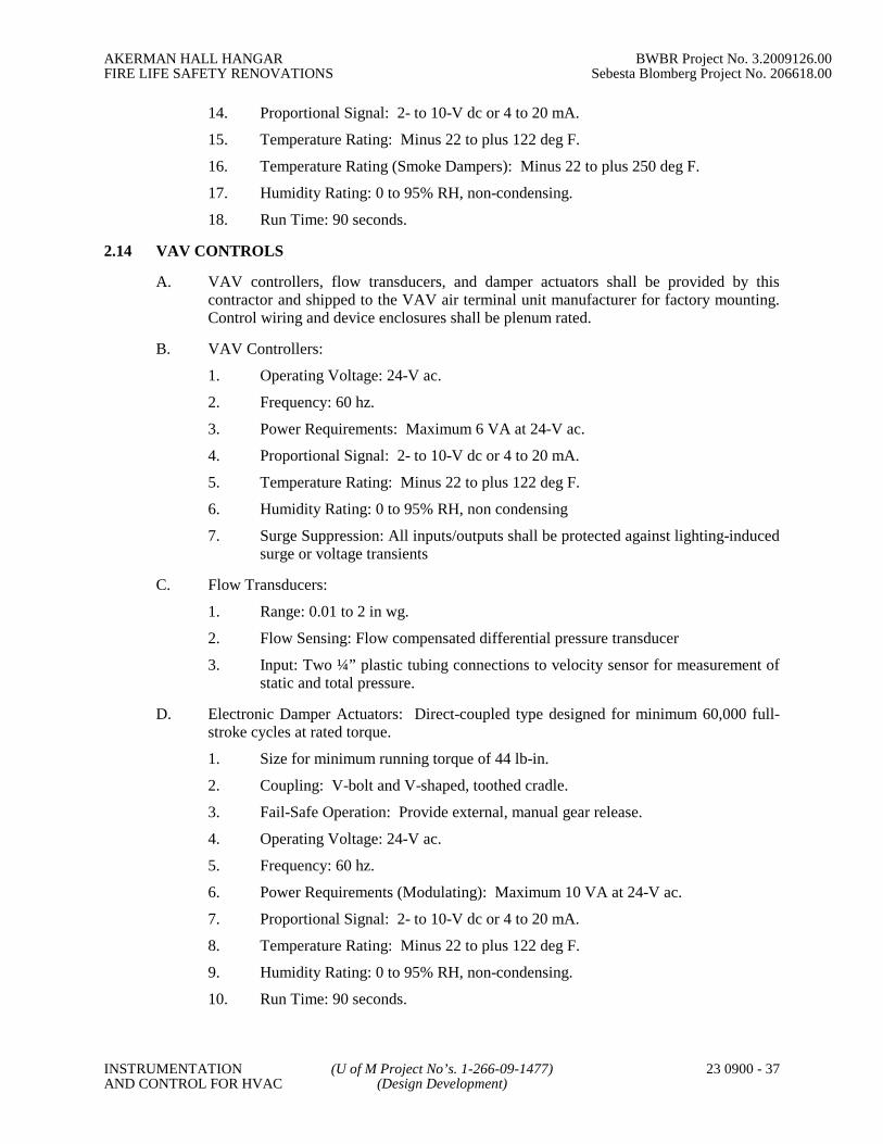
AKERMAN HALL HANGAR BWBR Project No. 3.2009126.00FIRE LIFE SAFETY RENOVATIONS Sebesta Blomberg Project No. 206618.00
INSTRUMENTATION (U of M Project No’s. 1-266-09-1477) 23 0900 - 37AND CONTROL FOR HVAC (Design Development)
14. Proportional Signal: 2- to 10-V dc or 4 to 20 mA.
15. Temperature Rating: Minus 22 to plus 122 deg F.
16. Temperature Rating (Smoke Dampers): Minus 22 to plus 250 deg F.
17. Humidity Rating: 0 to 95% RH, non-condensing.
18. Run Time: 90 seconds.
2.14 VAV CONTROLS
A. VAV controllers, flow transducers, and damper actuators shall be provided by thiscontractor and shipped to the VAV air terminal unit manufacturer for factory mounting.Control wiring and device enclosures shall be plenum rated.
B. VAV Controllers:
1. Operating Voltage: 24-V ac.
2. Frequency: 60 hz.
3. Power Requirements: Maximum 6 VA at 24-V ac.
4. Proportional Signal: 2- to 10-V dc or 4 to 20 mA.
5. Temperature Rating: Minus 22 to plus 122 deg F.
6. Humidity Rating: 0 to 95% RH, non condensing
7. Surge Suppression: All inputs/outputs shall be protected against lighting-inducedsurge or voltage transients
C. Flow Transducers:
1. Range: 0.01 to 2 in wg.
2. Flow Sensing: Flow compensated differential pressure transducer
3. Input: Two ¼” plastic tubing connections to velocity sensor for measurement ofstatic and total pressure.
D. Electronic Damper Actuators: Direct-coupled type designed for minimum 60,000 full-stroke cycles at rated torque.
1. Size for minimum running torque of 44 lb-in.
2. Coupling: V-bolt and V-shaped, toothed cradle.
3. Fail-Safe Operation: Provide external, manual gear release.
4. Operating Voltage: 24-V ac.
5. Frequency: 60 hz.
6. Power Requirements (Modulating): Maximum 10 VA at 24-V ac.
7. Proportional Signal: 2- to 10-V dc or 4 to 20 mA.
8. Temperature Rating: Minus 22 to plus 122 deg F.
9. Humidity Rating: 0 to 95% RH, non-condensing.
10. Run Time: 90 seconds.

AKERMAN HALL HANGAR BWBR Project No. 3.2009126.00FIRE LIFE SAFETY RENOVATIONS Sebesta Blomberg Project No. 206618.00
INSTRUMENTATION (U of M Project No’s. 1-266-09-1477) 23 0900 - 38AND CONTROL FOR HVAC (Design Development)
2.15 CONTROL VALVES
A. Control Valves: Factory fabricated, of type, body material, and pressure class based onmaximum pressure and temperature rating of piping system, unless otherwise indicated.
B. Globe Valves NPS 2 and Smaller: Bronze body, stainless stem, rising stem, renewablecomposition disc, and screwed ends with backseating capacity repackable underpressure.
C. Globe Valves NPS 2-1/2 and Larger: Iron body, stainless stem, rising stem, plug-typedisc, flanged ends, and renewable seat and disc.
D. Hydronic system globe valves shall have the following characteristics:
1. Rating: Class 125 for service at 125 psig and 190 deg F operating conditions.
2. Internal Construction: Replaceable plugs and seats of stainless steel or brass.
a. Single-Seated Valves: Cage trim provides seating and guiding surfacesfor plug on top and bottom of guided plugs.
b. Double-Seated Valves: Balanced plug; cage trim provides seating andguiding surfaces for plugs on top and bottom of guided plugs.
3. Sizing: 5-psig maximum pressure drop at design flow rate.
4. Flow Characteristics: Two-way valves shall have equal percentagecharacteristics; three-way valves shall have linear characteristics. Operatorsshall close valves against pump shutoff head.
E. Steam system globe valves shall have the following characteristics:
1. Rating: Class 125 for service at 125 psig and 250 deg F operating conditions.
2. Internal Construction: Replaceable plugs and seats of stainless steel.
a. Single-Seated Valves: Cage trim provides seating and guiding surfacesfor plug on top and bottom of guided plugs.
b. Double-Seated Valves: Balanced plug; cage trim provides seating andguiding surfaces for plugs on top and bottom of guided plugs.
3. Sizing: 10-psig inlet pressure and 5-psig pressure drop.
4. Flow Characteristics: Modified linear characteristics.
F. Terminal Unit Control Valves: Bronze body, stainless stem, two- or three-port asindicated, replaceable plugs and seats, union and threaded ends.
1. Rating: Class 125 for service at 125 psig and 250 deg F operating conditions.
2. Sizing: 3-psig maximum pressure drop at design flow rate, to close againstpump shutoff head.
3. Flow Characteristics: Two-way valves shall have equal percentagecharacteristics; three-way valves shall have linear characteristics.
2.16 DAMPERS
A. Outside and Relief Air Dampers (Insulated): The dampers specified below shall be usedfor modulating and two position control of outside, relief, and exhaust air.

AKERMAN HALL HANGAR BWBR Project No. 3.2009126.00FIRE LIFE SAFETY RENOVATIONS Sebesta Blomberg Project No. 206618.00
INSTRUMENTATION (U of M Project No’s. 1-266-09-1477) 23 0900 - 39AND CONTROL FOR HVAC (Design Development)
1. Fabrication:
a. Frame: 5 in. x 1 in. 16 ga. galvanized steel hat channel. Reinforcedcorners.
b. Blades:
(1) Style: Insulated, airfoil shaped, filled with ½ in. polystyrene.(2) Action: Parallel or opposed blade as indicated on control
drawings.(3) Orientation: Horizontal or vertical with thrust washers.(4) Material: Galvanized steel double skin construction 14 ga.
equivalent thickness(5) Width: Maximum 6 inches.
c. Bearings: Synthetic (acetal) sleeve type.
d. Seals:
(1) Blade: Extruded silicone blade seals mechanically attached toblade edge.
(2) Jamb: Extruded silicone.
e. Linkage: Concealed in frame.
f. Axles: Minimum 1/2-inch diameter plated steel, hex-shaped,mechanically attached to blade.
g. Mounting: Vertical or horizontal as shown on drawings or as requiredfor serviceable installation.
h. Finish: Galvanized steel.
2. Performance Data:
a. Temperature Rating: Withstand -72 to 275 degrees F.
b. Capacity: Demonstrate capacity of damper to withstand HVAC systemoperating conditions.
(1) Closed Position: Maximum pressure of 8.0 inches w.g. at a 12-inch blade length.
(2) Open Position: Maximum air velocity of 4,000 feet per minute.
c. Leakage: Maximum 6.0 cubic feet per minute per square foot at 4 inchesw.g. for size 48 x 48 inches.
d. Pressure Drop: Maximum 0.07 inch w.g. at 1,500 feet per minute across24 inch x 24 inch damper in a fully ducted configuration as tested perAMCA Standard 500.
B. Return Air Dampers (Non-insulated): The dampers specified below shall be used formodulating and two position control of return, mixed, and supply air.
1. Fabrication:
a. Frame: 5 inches x 1 inch x minimum 0.125 inch (127 x 25 x minimum3.2 mm) 6063-T5 extruded aluminum hat-shaped channel, mountingflanges on both sides of frame, reinforced at corners.
b. Blades:
(1) Style: Airfoil-shaped, single-piece.

AKERMAN HALL HANGAR BWBR Project No. 3.2009126.00FIRE LIFE SAFETY RENOVATIONS Sebesta Blomberg Project No. 206618.00
INSTRUMENTATION (U of M Project No’s. 1-266-09-1477) 23 0900 - 40AND CONTROL FOR HVAC (Design Development)
(2) Action: Parallel or opposed blade as indicated on controldrawings.
(3) Orientation: Horizontal or vertical with thrust washers.(4) Material: Heavy duty 6063-T5 extruded aluminum.(5) Width: Maximum 6 inches.
c. Bearings: Molded synthetic sleeve, turning in hole in frame.
d. Seals:
(1) Blade: Inflatable seal blade edging, or replaceable rubber sealsfor ultra-low leakage from -72 to 275 degrees F. Mechanicallyattached to blade edge.
(2) Jamb: Flexible metal compression type.
e. Linkage: Concealed in frame.
f. Axles: Minimum 1/2 inch diameter plated steel, hex-shaped,mechanically attached to blade.
g. Mounting: Vertical or horizontal as shown on drawings or as requiredfor serviceable installation.
h. Finish: Mill aluminum.
2. Performance Data:
a. Temperature Rating: Withstand -72 to 275 degrees F.
b. Capacity: Demonstrate capacity of damper to withstand HVAC systemoperating conditions.
(1) Closed Position: Maximum pressure of 13 inches w.g. at a 12-inch blade length.
(2) Open Position: Maximum air velocity of 6,000 feet per minute.
c. Leakage: Maximum 5.2 cubic feet per minute per square foot at 4 inchesw.g. for size 48 x 48 inches.
d. Pressure Drop: Maximum 0.03 inch w.g. at 1,500 feet per minute across24 inch x 24 inch damper in a fully ducted configuration as tested perAMCA Standard 500.
2.17 OTHER EQUIPMENT REQUIREMENTS
A. At a minimum, building level controllers and unit level controllers monitoring and/ortransmitting fire alarm points shall have UL 864 UOJZ listing with UnderwritersLaboratories. The controls contractor shall provide a copy of the UL certificate for theircontrollers.
B. All controllers used for smoke control shall be UL 864 UUKL listed.
C. If the DDC system is controlling a piece of equipment that is on emergency power, theDDC panel shall be connected to the same source of emergency power.
D. All DDC primary LAN controllers, PCs and communication equipment that monitor lifesafety and critical points (such as fire alarm and elevator emergency) shall be connectedto emergency power and have an online UPS with full-load rectification and inversion(double conversion). If a generator supports the electrical circuit, then four-hour UPS isrequired. If a generator does not support the electrical circuit, then 24-hour UPS is

AKERMAN HALL HANGAR BWBR Project No. 3.2009126.00FIRE LIFE SAFETY RENOVATIONS Sebesta Blomberg Project No. 206618.00
INSTRUMENTATION (U of M Project No’s. 1-266-09-1477) 23 0900 - 41AND CONTROL FOR HVAC (Design Development)
required. The University must approve any deviations from this requirement in writingprior to bidding.
E. Operating system for the building level network controller shall be Windows XPProfessional or the most recent release of Windows.
2.18 HVAC CONTROL HARDWARE IDENTIFICATION
A. Automatic Control Valve Tags
1. Use metal tags with a 2-inch minimum diameter, fabricated of brass, stainlesssteel, or aluminum. Attach the tags with a chain of the same material.
2. For lubrication instructions, use linen or a heavy duty shipping tag.
3. Tag the valves with identifying number and system.
4. Prepare a list of all tagged valves showing location, floor level, tag number, anduse. Organize the list by system. Include copies in each maintenance manual.
B. Wire Tags: All multi-conductor cables in all pull boxes and terminal strip cabinets shallbe tagged.
C. Conduit Tags: Provide tagging or labeling of all conduits so that it is readily observablewhich conduit was installed or used in implementation of this work.
D. Panels and Control Devices
1. Control Panels (Enclosures) shall be labeled.
2. All sensors, controllers, and controlled devices shall also be labeled.
3. Where physical space permits, the labels shall be made of black lamicoid sheetwith white lettering. They shall be affixed to the panel or device by screws ifpossible or glue if screws are not feasible. If physical space does not permit theuse of labels with readable text, tags shall be used.
4. Identification on the labels or tags shall match the identification documented onthe submittals/as-builts.
PART 3 - EXECUTION
3.1 EXAMINATION
A. Verify existing conditions before starting work. The beginning of installation impliesthat the contractor accepts the existing conditions.
B. The contractor shall thoroughly examine the project plans for control device andequipment locations, and any discrepancies, conflicts, or omissions shall be reported tothe Engineer for resolution before rough-in work is started.
C. The contractor shall inspect the site to verify that equipment is installable as shown, andany discrepancies, conflicts, or omissions shall be reported to the Engineer for resolutionbefore rough-in work is started.
D. The contractor shall examine the drawings and specifications and if head room or spaceconditions appear inadequate or if any discrepancies occur between the plans for workunder this contract and the plans for the work of others, the discrepancies shall be

AKERMAN HALL HANGAR BWBR Project No. 3.2009126.00FIRE LIFE SAFETY RENOVATIONS Sebesta Blomberg Project No. 206618.00
INSTRUMENTATION (U of M Project No’s. 1-266-09-1477) 23 0900 - 42AND CONTROL FOR HVAC (Design Development)
reported to the Engineer and the contractor shall obtain written instructions for anychanges necessary to accommodate the work under this contract with the work of others.
3.2 PROTECTION
A. The contractor shall protect against and be liable for damage to work and to materialcaused by the contractor’s work or employees.
B. The contractor shall be responsible for work and equipment until inspected, tested, andaccepted.
C. The contractor shall be responsible for protecting materials awaiting installation.
D. The contractor shall close open ends of work with temporary covers or plugs duringstorage and construction to prevent entry of foreign objects.
3.3 COORDINATION
A. Site
1. The contractor shall assist in coordinating space conditions to accommodate thework of each trade where work will be installed near or will possibly interferewith work of other trades. If installation with coordination causes interferencewith work of other trades, the contractor shall correct conditions without extracharge.
a. Coordinate and schedule work with work in the same area and with workthat is dependent upon other work to facilitate mutual progress.
B. Submittals: See Part 1
C. Test and Balance
1. The contractor shall provide the Test and Balance Contractor a single set ofnecessary tools to interface with the control system for testing and balancing.
2. The contractor shall provide a minimum of 4 hours of training on the use of theinterface tools.
3. The contractor shall provide a qualified technician to assist with the testing andbalancing of one system controlled by a programmable controller and the firsttwenty terminal units.
4. The Test and Balance contractor is obligated to return the interface toolsundamaged and in working condition at completion of the testing and balancing.
D. Network
1. The contractor shall allocate space in each Building Controller control panel forthe installation of a network switch. The size of the network switch shall beselected such that a minimum of one spare port is available at each control panelat the completion of the project.
E. Life Safety
1. Duct smoke detectors required for air handler shutdown are provided underDivision 26. The contractor shall interlock the smoke detectors to the airhandlers for shutdown as required by the sequence of control.

AKERMAN HALL HANGAR BWBR Project No. 3.2009126.00FIRE LIFE SAFETY RENOVATIONS Sebesta Blomberg Project No. 206618.00
INSTRUMENTATION (U of M Project No’s. 1-266-09-1477) 23 0900 - 43AND CONTROL FOR HVAC (Design Development)
2. Smoke dampers and actuators required for duct smoke isolation are providedunder Division 23. The contractor shall interlock the smoke dampers to the airhandlers as required by the sequence of control.
3. Fire and smoke dampers and actuators required for fire-rated walls are providedunder Division 23. Fire and smoke damper control is provided under Division26.
F. Coordination with other controls specified in other sections or divisions: Other sectionsand/or division of this specification include controls and control devices that are to bepart of or interfaced to the control system specified in this section. The contractor shallcoordinate his integration of these devices as follows.
1. All communication media and equipment shall be provided as specified inSection XXXXX.
2. Each supplier of a controls product is responsible for the configuration,programming, start-up and testing of that product to meet the sequence ofcontrol.
3. The contractor shall coordinate and resolve any incompatibility issues that arisebetween the control products provided under this section and those providedunder other sections or divisions of this specification.
4. The contractor is responsible for providing all controls described in the contractdocuments regardless of where within the contract documents these controls aredescribed.
5. The contractor is responsible for the interface of control products provided bymultiple suppliers regardless of where this interface is described within thecontract documents.
G. Verify building posting requirements with the Owner, before starting work.
3.4 GENERAL WORKMANSHIP
A. The contractor shall install equipment, piping, and wiring/raceway parallel to buildinglines (i.e., horizontal, vertical, and parallel to walls) wherever possible.
B. The contractor shall provide sufficient slack and flexible connections to allow forvibration of piping and equipment.
C. The contractor shall install all equipment in readily accessible locations as defined byChapter 1, Article 100, Part A of the Nations Electrical Code (NEC).
D. The contractor shall verify the integrity of all wiring to ensure continuity and freedomfrom shorts and grounds.
E. All equipment, installation, and wiring shall comply with acceptable industryspecifications and standards for performance, reliability, and compatibility and beexecuted in strict adherence to local codes and standard practices.
F. Penetrations for raceway, piping, sleeves, or other equipment shall be sealed in a mannerconsistent with existing building conditions and current building code requirements.
G. Limit dust and dirt dispersal to lowest practicable level. Comply with governingregulations regarding environmental hazards and general dust control. Notify the
AKERMAN HALL HANGAR BWBR Project No. 3.2009126.00FIRE LIFE SAFETY RENOVATIONS Sebesta Blomberg Project No. 206618.00
INSTRUMENTATION (U of M Project No’s. 1-266-09-1477) 23 0900 - 44AND CONTROL FOR HVAC (Design Development)
Owner’s Representative of possible exposure to harmful dusts and vapors, flammable orexplosive materials, and other potential hazards. See Appendix B - Dust, Contaminantand Odor Control Options. Patch to match existing adjacent materials. When identicalpatching materials are not available, review alternatives with Owner’s Representative.
3.5 FIELD QUALITY CONTROL
A. All work, materials, and equipment shall comply with the rules and regulations ofapplicable local, state, and federal codes and ordinances as identified in Part 1 of thisspecification.
B. The contractor shall continually monitor the field installation for code compliance andquality of workmanship.
C. The Contractor shall have work inspected by local and/or state authorities havingjurisdiction over the work.
3.6 CONTINUITY OF EXISTING SYSTEM OPERATION
A. The contractor shall make all reasonable efforts to mitigate the impact of this work onthe operation of existing systems, building occupants, and research equipment.
B. Notify the owner prior to commencing work that could or will disrupt the functions ofany building or network systems. The contractor and owner will plan the detailedimplementation of the contractor’s work plan submitted with the proposal.
C. The contractor shall make provisions to maintain adequate continuous system operationfor equipment that serves critical research areas and all research animal holding areas.
D. Where building DDC systems are used for fire alarm signaling, the contractor shall makeprovisions to maintain this function during construction. The fire alarm signaling can bedisabled for construction during first shift if:
1. Approved by the owner.
2. BSAC fire system outage notification procedures are followed.
3. Proper fire watch procedures are followed.
4. The system is back online before the contractor leaves the jobsite each day.
E. The contractor shall notify BSAC and the FM maintenance district prior to disrupting theoperation of any existing equipment or system. Notification will also be made when theaffected systems are back in operation.
3.7 EXPOSED WORK
A. The controls contractor shall not run any conduit or wiring exposed below the finishedceiling or on any finished walls, unless approved by the Owner. The controls contractorshall be responsible for all cutting and patching required in connection with his work.The Owner shall approve all cutting and patching.
3.8 ENCLOSURES
A. All building controllers and/or enclosures shall be clearly labeled with their device IDand IP address.
B. Mark all DDC panels with circuit number and electrical panel number.

AKERMAN HALL HANGAR BWBR Project No. 3.2009126.00FIRE LIFE SAFETY RENOVATIONS Sebesta Blomberg Project No. 206618.00
INSTRUMENTATION (U of M Project No’s. 1-266-09-1477) 23 0900 - 45AND CONTROL FOR HVAC (Design Development)
3.9 WIRING
A. Licensed union electricians, experienced in this type of work shall perform all electricalwork. The Contractor shall be responsible for all control wiring required for the properinstallation of the system.
B. All power, control, and interlock wiring shall comply with national, state and localelectrical codes and Division 16 of this specification. Where the requirements of thissection differ from those in Division 16, the requirements of this section shall takeprecedence.
C. All components/devices used in wiring shall be UL/ETL approved, listed and stamped.All cable material and installation shall comply with State of Minnesota Fire Coderequirements.
D. Surge transient protection shall be incorporated in design of system to protect electricalcomponents in field panels.
E. Pathway/Raceway Construction
1. All raceway construction shall be in accordance with the latest revision of theNEC and Division 16 requirements. The pathway shall be minimum EMT with aflexible section for connection to devices, or PVC (polyvinyl chloride) wherecorrosion is expected to be a problem. Pathway which has been crushed ordeformed in any way shall not be installed.
2. Bends of pathway system shall be made such that the pathway shall not beinjured and that the internal diameter of the conduit will not be effectivelyreduced. The radius of the curve shall not be less that that recommended byeither the NEC or manufacturer of the wires or cable to be contained within thepathway. Wherever possible, the maximum angle of bends between pulls shallnot total more than 270 degrees including the entrance to and from the pull box.
3. The maximum allowable distance between pull points shall be 300 feet. Whenthe distance between the two pull points contains bends, the maximum allowabledistance shall be 75 feet. A lubricating agent compatible with the wire insulationshall be used. The pull boxes shall be sized to allow for an adequate bendingradius for the wire or cable being pulled.
4. The combined cross-sectional area of all conductors and cables shall not exceed40% of the total cross-sectional area of the pathway. The minimum size ofpathway is ¾ inches in diameter. Pathway on equipment to end devicesminimum size will be ½ inches and no longer than 3 feet.
5. Pathway shall be firmly supported within one meter or 3 feet of each pull box,junction box or termination point. The pathway shall be sufficiently supportedelsewhere in accordance with NEC requirements. Pathway runs shall be solidlyconnected to assure the ground continuity of the entire length. Ground jumpersshall be installed where the possibility of losing continuity exists.
6. Pathway runs shall be provided with condensation drains at low points. Pathwayruns shall be parallel or perpendicular to building walls.
7. Conduit Supports
a. Single runs: Galvanized conduit straps or ring bolt type hangers withspecialty spring clips. Do not use plumber’s perforated straps.

AKERMAN HALL HANGAR BWBR Project No. 3.2009126.00FIRE LIFE SAFETY RENOVATIONS Sebesta Blomberg Project No. 206618.00
INSTRUMENTATION (U of M Project No’s. 1-266-09-1477) 23 0900 - 46AND CONTROL FOR HVAC (Design Development)
b. Multiple runs: Conduit rack with 25 percent spare capacity.
c. Vertical runs: Channel support with conduit fittings.
d. Anchor Methods
(1) Hollow masonry: Toggle bolts or spider type expansionanchors.
(2) Solid masonry: Lead expansion anchors or present inserts.(3) Metal surfaces: Machine screws, bolts, or welded studs.(4) Wood surfaces: Wood screws.(5) Concrete surfaces: Self drilling anchors or power driver studs.
8. The size of raceway and size and type of wire shall be the responsibility of thecontractor, in keeping with the manufacturer’s recommendations and NECrequirements, except as noted elsewhere.
9. EMT and rigid conduit size shall be ¾” or greater.
10. Covers for J-Boxes used with DDC system wiring shall be painted green and/orstenciled with “DDC”.
11. Include one pull string in each raceway that is 1 inch in diameter or larger.
12. Conceal all raceways, except within mechanical, electrical, or service rooms.Install raceway to maintain a minimum clearance of 6 inches from high-temperature equipment such as steam pipes or flues.
13. Secure raceways with raceway clamps fastened to the structure and spacedaccording to code requirements. Raceways and pull boxes may not be hung onflexible duct strap or tie rods. Raceways may not be run on or attached toductwork.
14. Adhere to Division 16 requirement where raceway crosses building expansionjoints.
15. Install insulated bushings on all raceway ends and openings to enclosures. Sealtop end of all vertical raceways.
16. Flexible metal raceways and liquid-tight, flexible metal raceways shall notexceed 3 feet in length and shall be supported at each end. Flexible metalraceway less than ½ inch electrical trade size shall not be used. In areas exposedto moisture, including chiller and boiler rooms, liquid-tight, flexible metalraceways shall be used.
17. Raceway must be rigidly installed, adequately supported, properly reamed atboth ends, and left clean and free of obstructions. Raceway sections shall bejoined with coupling according to code. Terminations must be made withfittings at boxes and ends not terminating in boxes shall have bushings installed.
F. Class 1 Wiring
1. All NEC Class 1 (line voltage) wiring shall be UL Listed in approved racewayaccording to NEC and Division 16 requirements.
2. Maximum allowable voltage for control wiring shall be 120 Volts. If onlyhigher voltages are available, the contractor shall provide step-downtransformers.
G. Low Voltage (Class 2) Wiring
AKERMAN HALL HANGAR BWBR Project No. 3.2009126.00FIRE LIFE SAFETY RENOVATIONS Sebesta Blomberg Project No. 206618.00
INSTRUMENTATION (U of M Project No’s. 1-266-09-1477) 23 0900 - 47AND CONTROL FOR HVAC (Design Development)
1. Low voltage wiring shall meet NEC Class 2 requirements. Sub-fuse low voltagepower circuits as required to meet Class 2 current limits. Maximum controltransformer size is 100VA without prior approval form Owner.
2. Class 2 wiring installed above hard ceilings or other inaccessible locations shallbe run in approved raceway.
3. All exposed Class 2 wiring shall be enclosed in metallic conduit or raceway.
4. All wiring in mechanical, electrical, or service rooms, or where subject tomechanical damage, shall be installed in raceway at levels below 10 feet.
5. Low voltage wiring installed above lay-in or other accessible ceilings shall be inconduit unless specifically allowed by the University. If allowed, open cableinstallations will adhere to the requirements of this section.
6. Where NEC Class 2 (current-limited) wires are in concealed and accessiblelocations, including ceiling return air plenums, approved cables not in racewaymay be used provided that cables are UL Listed for the intended application.
7. Install plenum wiring in sleeves where it passes through walls and floors.Maintain the fire rating at all penetrations.
8. Where Class 2 wiring is run without raceways:
a. Wiring is to be run parallel along a surface or perpendicular to it
b. Wiring will be neatly tied at 10 foot intervals or less as required toprevent excessive sagging.
c. Wiring shall be supported from or anchored to structural members.Cables shall not be supported by or anchored to ductwork, electricalraceways, piping, or ceiling suspension systems.
9. The contractor shall not install Class 2 wiring in raceway containing Class 1wiring. Boxes and panels containing high-voltage wiring and equipment maynot be used for low-voltage wiring except for the purpose of interfacing the two(e.g., relays and transformers).
10. The contractor shall not install wiring in raceway containing pneumatic tubing.
11. All wire-to-device connections shall be made at a terminal block or terminalstrip. All wire to wire connections shall be at a terminal block.
12. All wiring within enclosures shall be neatly bundled and anchored to permitaccess and prevent restriction to devices and terminals.
13. All wiring shall be installed as continuous lengths, with no splices permittedbetween termination points.
14. Use coded conductors throughout with conductors of different colors.
H. Other Requirements
1. Control and status relays are to be located in designated enclosures only. Theseenclosures include packaged equipment control panel enclosures unless they alsocontain Class 1 starters.
2. The contractor shall terminate all control and/or interlock wiring and shallmaintain updated as-built wiring diagrams with terminations identified at the jobsite.

AKERMAN HALL HANGAR BWBR Project No. 3.2009126.00FIRE LIFE SAFETY RENOVATIONS Sebesta Blomberg Project No. 206618.00
INSTRUMENTATION (U of M Project No’s. 1-266-09-1477) 23 0900 - 48AND CONTROL FOR HVAC (Design Development)
3. Unless required for life safety system operation, wire all safeties so the fan shutsdown even if the HOA switch is in the hand position. On a fan system withVFDs, wire the safeties so the fan shuts down if the VFD is in hand or bypassmode of operation.
3.10 COMMUNICATION WIRING
A. The contractor shall adhere to the items listed in the previous section on WIRING.
B. The contractor shall install all cabling in a neat and workmanlike manner. Followmanufacturer’s installation recommendations for all communication cabling.
C. The contractor shall not install communication wiring in raceway and enclosurescontaining Class 1 wiring.
D. When a cable enters or exits a building, the contractor shall install a lightning arrestorbetween the lines and ground. The lightning arrestor shall be installed according to themanufacturer’s instructions.
E. The contractor shall install all runs of communication wiring with un-spliced lengthswhen that length is commercially available.
F. The contractor shall label all communication wiring to indicate origination anddestination data.
G. The contractor shall ground coaxial cable in accordance with NEC regulations on“Communications Circuits, Cable, and Protector Grounding.”
H. When shielded wiring is use, the contractor shall ground the shield only once for eachcontinuous segment of cable. The grounding location shall be at the end of the segmentthat is most readily accessible.
3.11 NETWORK COMMUNICATION TRUNK AND TERMINATIONS
A. A backbone communication trunk will be provided and installed by the University ofMinnesota. All network fiber shall be 62.5 micron FDDI grade. The University willprovide the fiber connection in one location in the building. The controls contractor isresponsible for all DDC network wiring within the building.
B. The controls contractor shall tag all fiber or copper cable with a tag indicating “BSACFiber or BSAC Cable.” All lower level panel-to-panel networking and fiber patch cordsshall be the responsibility of the controls contractor.
C. The controls contractor shall connect the new system to the dedicated fibercommunication trunk and provide all components necessary (hubs, switches, links,modems, connectors, cables, interface equipment, software, labor, etc.) forcommunication on the dedicated University DDC network to the vendor’s master workstation. Hub and switch locations shall be supported by a four hour UPS, provided bythe University, and emergency power.
D. The controls contractor shall provide a network riser for all locations as part ofconstruction, submittals and as-built documents. All fiber and network devices shall beclearly marked.
AKERMAN HALL HANGAR BWBR Project No. 3.2009126.00FIRE LIFE SAFETY RENOVATIONS Sebesta Blomberg Project No. 206618.00
INSTRUMENTATION (U of M Project No’s. 1-266-09-1477) 23 0900 - 49AND CONTROL FOR HVAC (Design Development)
3.12 IP INTERFACE DEVICES
A. Install Building Controllers for each required connection to the dedicated DDC TCP/IPnetwork.
B. The Building Controllers shall be configured and commissioned to ensure that the onlydata traffic on the TCP/IP is data that is essential for operation of the system. Messagesbetween field devices on the same field bus shall not be allowed to pass onto the TCP/IPnetwork.
3.13 SENSORS
A. The contractor shall install sensors in accordance with the manufacturer’srecommendations.
B. The contractor shall mount sensors rigidly and adequately for the environment withinwhich the sensor operates.
C. The contractor shall install all sensors in accessible locations.
D. Room temperature sensors shall be installed on concealed junction boxes properlysupported by the wall framing.
E. All wires attached to sensors shall be air sealed in their raceways or in the wall toprevent air transmitted from other areas from affecting sensor readings.
F. Sensors used in mixing plenums and hot and cold decks shall be of the averaging type.Averaging sensors shall be installed in a serpentine manner vertically across the duct.Each bend shall be supported with a capillary clip.
G. Low-limit sensors used in mixing plenums shall be installed in a serpentine mannerhorizontally across the duct. Each bend shall be supported with a capillary clip. Provide1 foot of sensing element for each square foot of coil area.
H. All pipe-mounted temperature sensors shall be installed in wells. Install all liquidtemperature sensors with heat-conducting fluid in the thermal wells.
I. Install outdoor air temperature sensors on the north wall, complete with a sun shield atthe designated location.
J. Differential air static pressure sensors:
1. For supply duct static pressure, pipe the high pressure tap to a duct probe thatmeasures at a 90 degree angle to flow (to measure only the static pressure andnot the effects of velocity). Pipe the low-pressure port to the plenum.
2. For return duct static pressure, pipe the low pressure tap to a duct probe thatmeasures at a 90 degree angle to flow (to measure only the static pressure andnot the effects of velocity). Pipe the high-pressure port to the plenum.
3. For building static pressure, pipe the low-pressure port of the sensor to the staticpressure port located on the outside of the building through a high-volumeaccumulator. Pipe the high-pressure port to a location behind a thermostat cover.
4. The piping to the pressure ports on all pressure transducers shall contain acapped test port located adjacent to the transducer.

AKERMAN HALL HANGAR BWBR Project No. 3.2009126.00FIRE LIFE SAFETY RENOVATIONS Sebesta Blomberg Project No. 206618.00
INSTRUMENTATION (U of M Project No’s. 1-266-09-1477) 23 0900 - 50AND CONTROL FOR HVAC (Design Development)
5. Mount transducers in a location accessible for service without the use of laddersor special equipment to the maximum extent possible.
K. All water differential pressure sensors shall have gauge tees mounted adjacent to thetaps. Water gauges shall also have shutoff valves installed before the tee.
L. Annular pitot tubes shall be installed so that the total head pressure ports are set-in-linewith the pipe axis upstream and the static port facing downstream. The total headpressure ports shall extend diametrically across the entire pipe. Annular pitot tubes shallnot be used where the flow is pulsating or where pipe vibration exists.
3.14 FLOW SWITCHES
A. Airflow Switches
1. Install in horizontal duct runs whenever possible.
2. If a vertical duct run is the only option, then install in a location with an upwardairflow.
B. Hydronic Switches
1. Use the correct paddle type for the pipe diameter as described by the switchmanufacturer.
2. Adjust the flow switch in accordance with the manufacturer’s instructions.
3.15 ACTUATORS
A. Damper actuators shall be provided with all mounting hardware and linkages.
B. Mount and link control damper actuators according to manufacturer’s instructions.
C. When spring return actuators are used on normally closed dampers, the seals shall becompressed when the dampers have been closed by the actuator.
D. Damper/actuator combinations shall modulate smoothly from fully closed to fully openand return.
E. Actuator Selection
1. Size damper actuators to operate the related control damper(s) with sufficientreserve power to provide smooth modulating action or two-position action.
2. Actuators shall also be sized for proper speed of response at the velocity andpressure conditions to which the control damper is subject.
3. Shall produce sufficient torque to close off against the maximum systempressures encountered.
4. Shall produce sufficient torque to close off against the fan shutoff pressure as aminimum.
5. The total damper area operated by an actuator shall not exceed 80% of themanufacturer’s maximum area rating. Provide at least one actuator for eachdamper section. Each damper actuator shall not power more than 20 square feetof damper area.
6. Use line shafting or shaft couplings (jackshafting) in lieu of blade-to-bladelinkages or shaft coupling when driving axially aligned damper sections.

AKERMAN HALL HANGAR BWBR Project No. 3.2009126.00FIRE LIFE SAFETY RENOVATIONS Sebesta Blomberg Project No. 206618.00
INSTRUMENTATION (U of M Project No’s. 1-266-09-1477) 23 0900 - 51AND CONTROL FOR HVAC (Design Development)
F. Electric/Electronic Damper Actuators
1. Shall be direct-mounted on the damper shaft or jackshaft unless shown as alinkage installation.
2. Shall be mounted following the actuator manufacturer’s recommendations.
G. Electric/Electronic Valve Actuators
1. Shall be connected to the valve with adapters approved by the actuatormanufacturer.
2. Shall be mounted following the actuator manufacturer’s recommendations.
3.16 CONTROL DAMPERS
A. Install dampers in accordance with the manufacturer’s instructions to operate and toobtain leakage rates specified herein. Adjust the damper linkage such that the dampercloses before the actuator is fully closed to assure tight shut-off of the damper.
B. Blank-off and seal around dampers and between dampers and sleeves or frames toeliminate air by-pass.
C. For outdoor air damper assemblies, stage the opening of each section to preventstratification and poor mixing of outside and return air.
3.17 CONTROL VALVES
A. Install in an accessible location, with room for actuator removal and service. Adjust theactuator to provide tight shutoff. Provide valve stem indicator and adjust to indicateproper travel.
B. Where butterfly valves are used, permanently mark the end of the valve shaft to indicatethe valve position.
3.18 WARNING LABELS
A. The contractor shall affix permanent warning labels to all equipment that can beautomatically started by the DDC system.
1. Labels shall use white lettering, 12 point type or larger, on a red background.
2. The labels shall read: “CAUTION: This equipment is operating underautomatic control and may start or stop at any time without warning. Switchdisconnect to the OFF position before servicing.”
B. The contractor shall affix permanent warning labels to all motor starters and all controlpanels that are connected to multiple power sources utilizing separate disconnects.
1. Labels shall use white lettering, 12 point type or larger, on a red background.
2. The labels shall read: “CAUTION: This equipment is fed from more than onepower source with separate disconnects. Disconnect all power sources beforeservicing.”

AKERMAN HALL HANGAR BWBR Project No. 3.2009126.00FIRE LIFE SAFETY RENOVATIONS Sebesta Blomberg Project No. 206618.00
INSTRUMENTATION (U of M Project No’s. 1-266-09-1477) 23 0900 - 52AND CONTROL FOR HVAC (Design Development)
3.19 IDENTIFICATION OF HARDWARE AND WIRING
A. The contractor shall label all wiring and cable, including that within factory-fabricatedpanels, at each end and within 2 inches of the end of the cable with the DDC address ortermination number.
B. The contractor shall label all pneumatic tubing at each end within 2 inches of the endwith a descriptive identifier.
C. The contractor shall label all control panels with minimum ½ inch letters on laminatedplastic nameplates.
D. The contractor shall identify all other control components with permanent labels. Allplug-in components shall be labeled on both the removable component and thepermanently installed base such that it is obvious where the removed component is to bere-installed.
E. The contractor shall label room sensors relating to terminal box or valves withnameplates.
F. Manufacturer’s nameplates and UL or CSA labels are to be visible and legible afterequipment is installed.
G. All identifiers shall match the as-built documents.
3.20 PROGRAMMING FOR PROGRAMMABLE DEVICES
A. These requirements apply to Building Controllers and Unit Level Controllers.
B. All process control loops for an integral system shall reside in a single controller.Examples of integral systems are:
1. Air handling units.
2. Packaged chillers.
3. Chillers, excluding pumps and tower.
4. Boilers.
C. To the maximum extent possible, all process control loops for built up systems shallreside in a single controller. An example is a chiller with its associated chilled water andcondenser water pumping systems or a boiler system with steam to hot water heatexchangers. The objective of this requirement is that the contractor shall use large pointcount primary controllers in lieu of multiple secondary controllers.
D. Supervisory logic for integral and built up systems may reside in building controllerswith the output commands to the process control loops traversing the field bus to thecontrollers executing the process control.
E. The contractor shall create and download application programs that meet therequirements of the sequence of operations, time scheduling requirements, trend loggingrequirements, alarm handling requirements and data visibility requirements at the OWS.
1. The contractor shall use the University point naming convention throughout theproject.

AKERMAN HALL HANGAR BWBR Project No. 3.2009126.00FIRE LIFE SAFETY RENOVATIONS Sebesta Blomberg Project No. 206618.00
INSTRUMENTATION (U of M Project No’s. 1-266-09-1477) 23 0900 - 53AND CONTROL FOR HVAC (Design Development)
2. All time schedules shall be fully configured with weekly schedules and all of theholidays identified by the owner.
3. All trend logs identified in the sequence of control shall be fully configured andoperational.
4. All alarm handling shall be consistent with University alarming standards. SeeAppendix B for current standards.
5. All application parameters identified as (adj) in the sequence of control shall beexposed as viewable parameters and appropriate initial values shall be set.
6. Manual control of all external points shall be configured with BACnet commandpriority eight (8) unless otherwise specified in the sequence of control.
7. For all variables broadcast onto the field bus, event driven communication shallbe used to avoid data storms. As a minimum the program shall provide for thesend on delta parameter and minimum send time parameter for each outputvariable.
8. The contractor shall embed into the programs sufficient comment statements toclearly describe each section of the program. This applies to both lineprogramming and graphical programming systems.
9. If graphical programming systems with multiple layers for the functional blockdiagrams are used, no more than two layers shall be used.
F. All device-to-device (peer-to-peer) data flow shall be in place and configured to meet thesequence of control.
G. The programmed applications for a single integrated system shall not be distributed overmore than one field bus. Examples:
1. A chiller is controlled by a controller on field bus number 1. The controllers thatcontrol the pumps and tower shall also be on field bus number 1 as these systemsare integrated in their control requirements.
2. Multiple air handling units are controlled by controllers on field bus number 1.The chiller system is controlled by controllers on field bus number 2. Thechiller control logic requires the chilled water valve positions from each of theair handling unit controllers. It is acceptable that these related but non-integralsystems are controlled by controllers on different field busses.
3.21 SERVERS AND WORKSTATIONS
A. The contractor shall install a data server and operator work stations as shown on thecontract drawings.
B. All required software for fully functional systems shall be installed and configured. Theowner shall provide the IP connections and identify the specific rooms where thecomputers shall be installed.
3.22 CLEANING AND FINISHING
A. The controls contractor shall maintain good housekeeping at all times. Keep the premisesfree from accumulations of waste materials or rubbish caused by execution of the work.At completion of the work the Contractor shall leave all work locations in a first classclean condition. In case of dispute, the Owner may remove the rubbish and charge the

AKERMAN HALL HANGAR BWBR Project No. 3.2009126.00FIRE LIFE SAFETY RENOVATIONS Sebesta Blomberg Project No. 206618.00
INSTRUMENTATION (U of M Project No’s. 1-266-09-1477) 23 0900 - 54AND CONTROL FOR HVAC (Design Development)
cost to the Contractor. The controls contractor shall be responsible for removing andreinstalling any ceiling tiles necessary to perform the work. Damaged tiles will bereplaced at the Contractors expense.
B. The entire project area shall be cleaned immediately prior to final inspection.
C. Each surface or unit shall be cleaned to the condition expected in a normal, commercialbuilding cleaning and maintenance program.
D. Cleaning shall include the interior of cabinets and casework, converters, unit heaters,radiation, electric panels, and similar items, and such accessible spaces as tunnels, shafts,pipe spaces, plenums, crawl spaces and similar areas.
E. When punch-list work generates dust and debris, an additional cleaning will be neededprior to occupancy.
3.23 SYSTEMS INTEGRATION
A. The controls contractor shall be fully responsible for the installation and commissioningof the integrated system.
B. Controls contractor shall be responsible for all on-site and off-site programming asrequired to provide a fully operational integrated system. Contractor shall coordinate allprogramming and point mapping requirements with University personnel. If theContractor deems changes to the Contract Documents necessary, submit details inwriting, to the Owner for approval.
C. The controls contractor shall provide all engineering and analysis work necessary todetermine the method of network connectivity. The Contractor shall furnish, install andprogram hardware, wiring, network devices, cabling, software and graphics to connectthe new DDC controls system to the University DDC network. The interface will allow,at a minimum, the following:
1. Alarm annunciation in BSAC
2. Output control
3. Analog and digital commands
4. Reset commands
5. Point enable and disable
6. Set point adjustments
7. Time Of Day Scheduling
8. Dynamic Alarm Synchronization
3.24 BUILDING SYSTEMS AUTOMATION NETWORK PERFORMANCEREQUIREMENTS
A. The temperature controls contractor will supply all hardware software labor, materialand expertise necessary to tie the BACnet building controller(s) to the University privateDDC control network. BACnet integration must conform to Data Link Layer OptionBACnet /IP shown in BACnet ANSI/ASHRAE 135-2004 publication Annex J.
B. The controls contractor must install all new building level controllers such that BACnetcommunications on the existing temperature control network are not derogated.

AKERMAN HALL HANGAR BWBR Project No. 3.2009126.00FIRE LIFE SAFETY RENOVATIONS Sebesta Blomberg Project No. 206618.00
INSTRUMENTATION (U of M Project No’s. 1-266-09-1477) 23 0900 - 55AND CONTROL FOR HVAC (Design Development)
Derogation includes router, switch, hub lockups, BACnet building controller lockups,site network excessive slowdowns, unnecessary and repeated ‘who is’ messages. Refer toASHRAE BACnet standard for definition of unnecessary Who-is messages.
C. All BACnet read property requests from the U of M Master BACnet OperatorWorkstation must not take more then 5 seconds to process once the BACnet BuildingController receives the read request. Object properties that are read requested thatrequire multiple segmented packets must not take more than 5 seconds to process therequest. All information that is received from a read property multiple or single readproperty must not be older that 10 seconds.
3.25 TRAINING:
A. The Control Contractor shall schedule twenty four (24) hours of system training with aminimum of two weeks notice.
1. All training must be held on-site.
2. An outline of the proposed agenda shall be submitted to Energy Management forreview.
3. Training shall be performed during normal working hours with project personnelwho are familiar with the full scope of the integration project and the vendor’sfront-end workstation.
4. The training shall consist of instructions in the proper operation, programming,and maintenance of the selected vendors system.
5. The Contractor shall instruct the Owner's personnel so that they can troubleshootand maintain integration hardware and databases, program, reprogram, and/orreenter the desired schedules, values, settings, and strategies.
3.26 DOCUMENTATION
A. The controls contractor shall provide three (3) bound copies of Owner's Manuals (i.e.equipment Data drawings with sequence of operations, Operational Manuals, As-builtdrawings, etc.)
B. The controls contractor will include control equipment drawings for each building.Submittal drawings will include network diagrams, panel layout drawings, detailedequipment drawings, description of operation, wiring diagrams, termination details, pointschedules, trunk layouts including power supplies at all bus levels, and room schedules.Drawings shall be “B” sized 11 inches x 17 inches. Submittal brochures will includedetailed product data sheets on all integration devices.
C. The controls contractor will include in the submittals a detailed point list for eachintegrated building. The point list shall detail the point descriptor, the type of input oroutput (i.e., DI, DO, AI, AO) and software points. The point list must be submitted to theOwner’s Representative for review and approval.
D. As-built drawings will each be stamped “As-Built” and have the as-built date on them.Copies of as-built drawings shall include the following at a minimum: Detailed drawingsfor each piece of controlled and monitored equipment, point lists, sequence ofoperations, hardware with part information, logic tables, room schedules, and O & Mmanuals. As part of the as-built drawings, the Contractor will provide a drawing thatshows the detailed routing of all communication trunk wires (building-to-building and
AKERMAN HALL HANGAR BWBR Project No. 3.2009126.00FIRE LIFE SAFETY RENOVATIONS Sebesta Blomberg Project No. 206618.00
INSTRUMENTATION (U of M Project No’s. 1-266-09-1477) 23 0900 - 56AND CONTROL FOR HVAC (Design Development)
within building), locations of all network and integration devices, front-end workstations,UPS and campus network/LAN connections.
E. The controls contractor shall provide electronic copies of all as-built documentation tothe University. The electronic copies shall be stored on CDs and shall be saved in aneditable format. Acceptable formats include Microsoft Office program formats (i.e.Word, Excel, Access, etc.), Visio, and AutoCAD. Other formats must be approved bythe University at time of project award.
3.27 CONTROL SYSTEM CHECKOUT
A. The contractor shall furnish all labor and test apparatus required to execute the start uptesting plan. Key tasks to be executed and documented in the start up testing reportinclude:
1. Verification of all primary and secondary voltages.
2. Verification that power wiring for all devices conforms to manufacturer’sinstructions.
3. Verification that all labeling is in place.
4. Inspection of wiring for loose strands and tight connections.
5. Verification of field bus topology, grounding of shields (if used) and installationof termination devices.
6. Verification that each I/O device is landed per the submittals and functions perthe sequence of control.
a. Analog sensors shall be properly scaled and a value reported to theOWS.
b. Binary sensors shall have the specified normal position and the state isreporting properly to the OWS.
c. Analog outputs have the specified normal position and move full strokewhen so commanded.
d. Binary outputs have the specified normal state and respond toenergize/de-energize commands.
7. Analog sensors calibrated with high quality instrumentation suitable for thesensor being calibrated.
a. The instruments shall display a current (12 month) NIST traceablecalibration sticker. Associated instrument calibration certificates shallbe made available within 24 hours of a request.
b. The measured value, reported value, and the calculated offset that wasentered into the database shall be recorded.
c. The calibration criteria shall be:
(1) Space Temperature: +/- 0.5 degrees F(2) Air Temperature: +/- 0.5 degrees F(3) Fluid Temperature: +/- 0.5 degrees F(4) Air Flow Rate: +/- 5 %(5) Liquid Flow Rate: +/- 5 %(6) Differential Pressure: +/- 3 %

AKERMAN HALL HANGAR BWBR Project No. 3.2009126.00FIRE LIFE SAFETY RENOVATIONS Sebesta Blomberg Project No. 206618.00
INSTRUMENTATION (U of M Project No’s. 1-266-09-1477) 23 0900 - 57AND CONTROL FOR HVAC (Design Development)
(7) Gauge Pressure: +/- 5%(8) Relative Humidity: +/- 3 % relative humidity(9) CO2: +/- 2 %
8. Loop Tuning
a. The contractor shall tune all P, PI and PID control loops.
b. The loop tuning criteria shall be a stable control loop where the averageerror over 15 minutes and 30 samples shall be less than:
(1) Space Temperature: +/- 0.75 degrees F(2) Air Temperature: +/- 1.50 degrees F(3) Air Humidity: +/- 5 % relative humidity(4) Chilled Water Temp: +/- 1.00 degrees F(5) Hot Water Temp: +/- 1.00 degrees F(6) Duct Pressure: +/- 0.2 inches w.g.
3.28 TESTING AND COMMISSIONING
A. The HVAC and control systems shall be commissioned in accordance with the projectCommissioning Plan. If no Commissioning Plan has been prepared, the systems shall becommissioning in accordance with ASHRAE Guideline 1-1996. The controls contractorshall provide assistance, staff and materials to support the commissioning activities.
B. All buildings transmitting fire alarm signals will be tested in accordance with the 2002EDITION of NFPA 72; 4.5 Documentation, 4.5.1; Approval and Acceptance, sub-section 4.5.1.2, 4.5.2; Completion Documents and 4.5.3 Records. Test transmission offire, trouble and supervisory signals. University of Minnesota staff and Code Officialsare available for consultation and testing support.
C. The controls contractor shall provide assistance, staff and materials to support thecommissioning activities in the presence of a designated University Representative,which shall include the following tests:
1. When installation is complete, verify and document communication transmissionbetween each building, the vendor’s master workstation, and any third partyBACnet work station. The controls contractor is responsible for all finaladjustments and testing. Submit test report to the Owners Representative as partof the final operational test.
2. Field test the accuracy of all points and verify that the vendor’s front end andthird party BACnet work station receives the change of states. Field point statusmust be in sync with the present alarm conditions, values, and status of pointsthat are mapped into the third party BACnet work station. Any device out of thespecified range shall be identified in the checkout report. All field controllerinformation for analog, digital, software points, etc, received at the integratedfront end, shall not be more then 10 seconds old.
3. All analog inputs shall be verified for accuracy according to the specificationsfor the device. Any device out of the specified range shall be replaced. Thedevices shall be tested against the calibrated instrument used in the initial setupof the device.
4. Switch the status of all digital inputs from the final field device. Verify thatBSAC received the change of state.

AKERMAN HALL HANGAR BWBR Project No. 3.2009126.00FIRE LIFE SAFETY RENOVATIONS Sebesta Blomberg Project No. 206618.00
INSTRUMENTATION (U of M Project No’s. 1-266-09-1477) 23 0900 - 58AND CONTROL FOR HVAC (Design Development)
5. The building control system shall provide commands to all outputs. Properoperation shall be verified in the field.
6. All DDC panels shall be tested for panel alarm condition and communicationtrunk will be tested for panel no response alarm conditions at the vendor’smaster workstation and at the MLWS.
D. All points shall be in the automatic mode when the project is turned over to theUniversity.
E. Verification Testing.
1. The University will perform verification tests on all equipment installed as partof this project.
2. The University will develop verification test plans for each system.
3. The controls contractor is responsible for providing materials and labor to assistthe University with verification testing. A University representative will witnessall verification testing.
4. The University will compile a log of open and deficient items observed duringthe testing.
a. The controls contractor shall complete all required repairs, test thesystem, and inform the University that the open and deficient items havebeen resolved within one week after receipt of the log.
b. The University will retest the corrected items to confirm they arecomplete. It is expected that the controls contractor will correct alldeficiencies in a timely manner and that multiple retesting by Universitystaff will not be required.
c. If more than one retest on the same system is required, the Universitymay back charge the controls contractor for all additional retests at a rateof $100/hr per person.
3.29 SERVICE AND SPARE PARTS
A. During the warranty period, the controls contractor shall provide service on hardwareand software components with technical staff located in the Minneapolis/St. PaulMetropolitan Area.
B. All service items and spare parts shall be available from the manufacturer orContractor’s stock for a minimum of 5 years following the expiration of the warrantyperiod.
3.30 ALARMS
A. Contractor shall configure alarms as required by the latest University DDC alarmguidelines in Appendix B.
B. The completed system must be capable of transmitting all fire alarms, emergency signalsand building control points from the selected vendors systems to the MLWS. A panelfailure alarm must be transmitted to the third party BACnet system when a DDCcontroller or network fails. Alarm conditions shall be printed and stored in an electronictext format for immediate and future reference.

AKERMAN HALL HANGAR BWBR Project No. 3.2009126.00FIRE LIFE SAFETY RENOVATIONS Sebesta Blomberg Project No. 206618.00
INSTRUMENTATION (U of M Project No’s. 1-266-09-1477) 23 0900 - 59AND CONTROL FOR HVAC (Design Development)
C. All binary alarm points shall be Normally Open contacts (closed contact mean alarm).
D. The controls contractor shall discuss with Energy Management the software proceduresfor specific types of alarm lockouts. If different limits are needed, the controls contractorshall get approval from Energy Management before programming alarm limits. Thecontrols contractor is responsible for high and low alarm limits for analog input points.All critical digital input points shall be programmed as alarmable points. All analog anddigital points for process equipment need to be reviewed with the process equipmentowner or building occupant for alarm conditions.
E. The vendor’s system and integrated system shall have the capability to recognize alarmpoint limits and alarm point lockouts from field panels for Dynamic AlarmSynchronization. On systems that are seasonal in operation or have alarm limitscontrolled based on control logic, the alarm reporting will be automatically overriddenwhen the equipment is shut off and the alarm condition shall read normal if the limits arewithin the alarm range.
F. All analog temperature, pressure, and other process variables shown in the alarmguidelines that are actively controlled by the DDC system shall be configured withdynamically resetting alarm limits linked to the control setpoint. The point shall be inalarm whenever the present value of the point is away from setpoint by more than theprogrammable deviation limit, subject to the alarm delays shown in the guidelines. Thedefault deviation limits for analog points are as follows:
1. Discharge Air Temperature: +/- 50F
2. Other AHU Temperatures: +/- 50F
3. Duct Static Pressure: +/- 0.2 in w.c.
4. Room Temperature: +/- 50F
5. Space Humidity: +/- 10%
6. Discharge Air Humidity: +/- 10%
7. Hot Water System Temperatures: +/- 50F
8. Chilled Water System Temperatures: +/- 30F
9. Hydronic System Pressures: +/- 10% of setpoint or 1 psi whichever is greater
G. All alarms must be routed to a BACnet notification class capable of routing BACnetalarms to a third party BACnet device. If applicable, alarmed points should be set toBACnet intrinsic. Proprietary alarming methods requiring use of vendor specificsoftware to view alarms are prohibited. Alarmable points must be routed to the properBSAC console operator terminal via a recipient entry into a BACnet notification classobject. Routing for Console 1 operator position includes the East Bank & NorthwestDistrict and University of Minnesota – Duluth (UMD). Console 3 operator positionincludes the Saint Paul District & Academic Health District. All intrinsic reporting mustalso be routed to the BSAC Master Alarm History Recorder which is located in the B30Donowe Building at BACnet device ID 123456. A BACnet Broadcast ManagementDevice has been initiated on each subnet. Additional BBMD support, when needed, isthe control contractor’s responsibility. BBMD must fully support foreign deviceregistration.

AKERMAN HALL HANGAR BWBR Project No. 3.2009126.00FIRE LIFE SAFETY RENOVATIONS Sebesta Blomberg Project No. 206618.00
INSTRUMENTATION (U of M Project No’s. 1-266-09-1477) 23 0900 - 60AND CONTROL FOR HVAC (Design Development)
3.31 SOFTWARE AND GRAPHICS
A. The controls contractor shall provide all necessary non-disclosure and licenseagreements for required software. Energy Management shall receive all softwarelicenses, the original copies of all software loaded into the system, and back-ups of allsystem databases and programs on CDs. All original software and documentation shallbe delivered to Energy Management in the Donhowe Building. During the project, thecontrols contractor shall maintain disk or CD copies of all data files, applicationprograms, and system software.
B. Two copies of all software and/or hardware needed to configure all control devices shallbe provided to the Owner at the completion of the project. This includes any softwaretools, cabling, disks, etc. needed to program, configure, and maintain building and unitlevel DDC devices along with all networking hardware provided as part of the project.
C. The controls contractor shall update all DDC controllers to the latest released version offirmware at the completion of the project. Identical controllers shall all have the samesoftware revision number when the project is complete.
D. The controls contractor shall make available and install DDC system and configurationsoftware fix packs and patches at no cost to the University during the warranty period.
E. The controls contractor shall make available and install DDC system and configurationsoftware version upgrades released during the warranty period at no cost to theUniversity.
F. When the controls contractor integrates the selected vendors system into the vendor’smaster workstation or third party BACnet system, all workstations shall be updated withthe new system software, databases, graphics, etc.
G. In coordination with the requirements, specifications, and existing operating conditionsthe controls contractor shall program all schedules, parameters, high/low limits, controlstrategies, alarm values, descriptor, engineering units, map all physical and softwarepoints into the vendor’s DDC panels/work-stations or third party BACnet system for acomplete operational system.
H. The DDC operator interface shall include all software programming required to add thenew building DDC databases and graphics to the existing DDC network in the DonhoweBuilding. The programmer for the DDC system shall map all physical and softwarepoints necessary for the operator to monitor and command all physical points and adjustall set points from the operator’s PC without requiring any additional programmodifications. The controls contractor shall verify and remove all points from thedatabase that are not used in the program. The controls contractor also shall beresponsible for all point mapping and input/output object creation. A minimum of eightpoints shall be mapped from all VAV controllers to the vendor’s master workstationand/or integrated system.
I. The addition of the vendors DDC points to the new subsystem shall not cause thatsubsystem or any other subsystem to stop functioning (crash) or slow down the requestfor point information. Subsystem start up synchronization between field panels and orvendor workstations and any subsystem shall not cause that subsystem or any othersubsystem to stop functioning (crash) or slow down the request for point information.

AKERMAN HALL HANGAR BWBR Project No. 3.2009126.00FIRE LIFE SAFETY RENOVATIONS Sebesta Blomberg Project No. 206618.00
INSTRUMENTATION (U of M Project No’s. 1-266-09-1477) 23 0900 - 61AND CONTROL FOR HVAC (Design Development)
J. All database programs shall be complied and/or de-compiled for errors before saving tothe master front-end hard drive. Follow the specific procedures for directory, path andfile names.
K. The controls contractor shall upload all DDC controller databases, including networkcontroller level DDC programs, to the vendors master workstation front end PC locatedin BSAC. Primary and secondary bus controllers, including VAV box controllers, shallbe uploaded and saved separately to the vendor’s master workstation.
L. The University shall have the capability to add, modify and delete time of day schedules,holiday schedules, weekday schedules, weekend schedules, temporary schedules, etc.from the vendor’s front end.
3.32 GRAPHIC STANDARDS FOR BUILDING SYSTEMS
A. Graphics shall be generated from the vendor’s template library. New graphics shall becreated at the vendor’s workstation. System graphics shall be developed for the vendorsDDC system or at the integrated operator’s workstations, not both. Discuss graphicdevelopment as part of the bid and design process. Vendor’s workstation graphics shallfollow all existing U of M graphic standards including ‘Fan Served Area served and‘Quick Reference’ text table sections. The University will provide the ‘Fan Served Area’in Auto-Cad version 14.
1. All hardware points shall have graphic(s) assigned
2. All user adjustable software points shall have graphic(s) assigned
3. Starting graphic for University campus with zones 1 through 5.
4. Each new building shall belong to one of the five zones.
5. Create graphic for outside conditions (Outside air, humidity, enthalpy, etc.)
6. The graphics shall note the analog output range and normal position.
B. Each piece of equipment shall have one or more graphics to include the following:
1. All hardware points
2. All user adjustable set points
3. All safety alarm points for the system (Fan, pump, static, freezestat, etc)
4. Heating/cooling switchover points
5. Occupancy/unoccupancy points
6. Summer/Winter mode points
7. Create graphic(s) for fire systems and other life and safety system alarms (Firesystem, carbon monoxide, oxygen depletion, etc).
8. Create graphic(s) for all other critical points (Elevator, control air, phase outage,generator, city water, etc.).
9. Create graphic for steam points (Steam pressures, flow meters, etc.).
10. Create separate graphic(s) when more than 5 identical type of alarm points aremonitored (Six cold rooms, ten incubators, etc.).
11. Create miscellaneous graphic(s) for other non-critical points (roof drain, sumppump, etc.).

AKERMAN HALL HANGAR BWBR Project No. 3.2009126.00FIRE LIFE SAFETY RENOVATIONS Sebesta Blomberg Project No. 206618.00
INSTRUMENTATION (U of M Project No’s. 1-266-09-1477) 23 0900 - 62AND CONTROL FOR HVAC (Design Development)
12. Create graphic(s) for building layout and network system configuration withidentifying the bus layout.
13. Verify that all programmed points on each graphic are referencing the correctsoftware/hardware point at the controller level.
C. Other graphic criteria:
1. All graphics systems shall use standard templates and colors.
2. Type of font and font sizes shall be identical when appropriate.
3. All text and controller points shall be aligned properly.
4. All points shall flash red when points are in alarm condition.
5. When screens have minimal information, maximize the usage of the screen byenlarging the graphic.
6. Use building equipment numbers when possible for all equipment.
7. Points and descriptors shall not overlap.
3.33 POINT NAMING/POINT LOGICAL GROUPING AND GRAPHICS
A. The programmer shall meet with Energy Management personnel before proceeding withprogramming to review point naming, system layout, point logical grouping, graphics,graphical display response time, and tree structure. The controls contractor shall contactEnergy Management personnel before deviating from University Standards. Failure towork within the University Standards may result in the on Contractor being required toredo their work without being compensated
B. Supervisory controllers must be named with their corresponding building number &panel number. Before database generation is started, controls contractors are advised tocontact Energy Management for questions regarding naming. Energy Managementreserves the right to require changes to point naming if the controls contractor does notclarify naming before start of the controller database(s).
C. BACnet Object Identification numbers must also include building number and panelnumber. Controls contractors must coordinate Object IDs & IP address information withEnergy Management prior to the start of database generation.

AKERMAN HALL HANGAR BWBR Project No. 3.2009126.00FIRE LIFE SAFETY RENOVATIONS Sebesta Blomberg Project No. 206618.00
INSTRUMENTATION (U of M Project No’s. 1-266-09-1477) 23 0900 - 63AND CONTROL FOR HVAC (Design Development)
APPENDIX A: U of M BACnet Object Support Requirements
Controls contractor shall complete and return Appendix A with their proposal. Controls contractors mustindicate Readable, Writable or Not Supported under Proposed Temperature Control Panel Conformancecolumn below for all object standards shown.
Standards Required Column Definition:
Optional: Indicates that the property is optional and is not required by U of M BSAC
Readable: Indicates that the property is required by the University to be present and readableusing BACnet services. This property will be read by the BSAC Master Operator Workstation.
Writable: Indicates that the property is required by the University to be present, readable, andwritable using BACnet services. This property will be read from and written to by the BSACMaster Operator Workstation.
Not Req: Indicates that the property is not required by the University to be present
Alarm and Event Services:
BACnet intrinsic to device alarming method is required by U of M BSAC. All standard object propertiesand services that are required by ANSI/ASHRAE BACnet Standard 135-2004 for use with intrinsicreporting are required by U of M BSAC. Standard U of M required objects that support intrinsicreporting:
If Present_Value changes to a new state for longer that Time_Delay AND the new transition is enabled inEvent_Enable an intrinsic alarm shall be sent for the following standard BACnet objects:
Binary InputBinary ValueMulti-state InputMulti-state Value
If Present_Value exceeds range between High_Limit and Low_Limit for longer than Time_Delay ANDthe new transition is enabled in Event_Enable and Limit_Enable an intrinsic alarm shall be sent for thefollowing standard BACnet objects:
Analog InputAnalog OutputAnalog Value
If Present_Value returns within the High_Limit - Deadband to Low_Limit + Deadband range forlonger than Time_Delay AND the new transition is enabled in Event_Enable and Limit_Enable anintrinsic return to normal shall be sent for the following standard BACnet objects:
Analog InputAnalog OutputAnalog Value
If Present_Value differs from Feedback_Value for longer than Time_Delay AND the new transition isenabled in Event_Enable an intrinsic alarm shall be sent for the following standard BACnet objects:
BACnet standard object type Binary OutputBACnet standard object type Multi-state Output
All BACnet Object definitions are standard types as defined by the ANSI/ASHRAE BACnet Standard135-2004. Custom or nonstandard BACnet objects supported by the Vendor must support the
AKERMAN HALL HANGAR BWBR Project No. 3.2009126.00FIRE LIFE SAFETY RENOVATIONS Sebesta Blomberg Project No. 206618.00
INSTRUMENTATION (U of M Project No’s. 1-266-09-1477) 23 0900 - 64AND CONTROL FOR HVAC (Design Development)
Object_Identifier, Object_Name and Object_Type properties as required by ASHRAE 135-2004. AllObject properties required by ASHRAE for instinsic reporting are required by U of M. If a standardBACnet object is not listed in this construction standard then it is not required. U of M requires supportfor 13 of the 23 ASHRAE 135-2004 standard objects. The U of M requires Confirmed Event NotificationService. All alarms sent to the U of M Master Operator Console Workstation and Master Alarm HistoryPC via Notification Class Object recipient list must be set to ‘Confirmed’.
The U of M requires foreign device registration support at control contractors BACnet BroadcastManagement Device (BBMD). The control contractor must support BBMD capabilities for eachindividual subnet.
Controls contractors that are unable to comply with BACnet schedule Object:If the controls contractor does not support the required schedule object including associated propertiesand services than the controls contractor will be required to submit a technical document that includesthe following:
A. Custom and proprietary schedule objects and properties which will include complete datatypeand ANSI data definitions. Controls contractor will be required submit, during the job submittalphase, all information that is necessary to properly read and write schedule data into controlscontractor proprietary schedule at a building panel level.
B. Submitted proprietary schedule object data must include:
Internal schedule ID, name, and description information Date range information when schedule is active (only if vendor supports this function) Weekly schedule information Holiday schedule information Exception or temporary schedule information that would take precedence over normal day’s
behavior List of references including points information that are connected to the schedule Command priority for writing schedules information

AKERMAN HALL HANGAR BWBR Project No. 3.2009126.00FIRE LIFE SAFETY RENOVATIONS Sebesta Blomberg Project No. 206618.00
INSTRUMENTATION (U of M Project No’s. 1-266-09-1477) 23 0900 - 65AND CONTROL FOR HVAC (Design Development)
Analog InputProperty Identifier
Analog InputProperty Datatype
StandardsRequired
ProposedTemperature ControlPanel Conformance
Object_Identifier BACnetObjectIdentifier ReadableObject_Name CharacterString ReadableObject_Type BACnetObjectType ReadablePresent_Value REAL Readable-1Description CharacterString Not ReqDevice_Type CharacterString Not ReqStatus_Flags BACnetStatusFlags ReadableEvent_State BACnetEventState ReadableReliability BACnetReliability Not ReqOut_Of_Service BOOLEAN ReadableUpdate_Interval Unsigned Not ReqUnits BACnetEngineeringUnit ReadableMin_Pres_Value REAL Not ReqMax_Pres_Value REAL Not ReqResolution REAL Not ReqCOV_Increment REAL Optional-2Time_Delay Unsigned Optional-3Notification_Class Unsigned Optional-3High_ Limit REAL Optional-3Low_Limit REAL Optional-3Deadband REAL Optional-3Limit_ Enable BACnetLimitEnable Optional-3Event_Enable BACnetEventTransitionBits Optional-3Acked_Transitions BACnetEventTransitionBits Optional-3Notify_Type BACnetNotifyType Optional-3Event_Time_Stamps BACnetARRAY[3]of
BACnetTimeStampOptional-3
Proile_Name CharacterString Not Req
1 This property is required to be writable when Out_Of_Service is TRUE.2 This property is required if the object supports COV reporting. (Not Required by the U of M)3 These properties are required if the object supports intrinsic reporting. (Required by the U of M)

AKERMAN HALL HANGAR BWBR Project No. 3.2009126.00FIRE LIFE SAFETY RENOVATIONS Sebesta Blomberg Project No. 206618.00
INSTRUMENTATION (U of M Project No’s. 1-266-09-1477) 23 0900 - 66AND CONTROL FOR HVAC (Design Development)
Analog OutputProperty Identifier
Analog OutputProperty Datatype
StandardsRequired
Proposed TemperatureControl PanelConformance
Object_Identifier BACnetObjectIdentifier ReadableObject_Name CharacterString ReadableObject_Type BACnetObjectType ReadablePresent_Value REAL WritableDescription CharacterString Not ReqDevice_Type CharacterString Not ReqStatus_Flags BACnetStatusFlags ReadableEvent_State BACnetEventState ReadableReliability BACnetReliability Not ReqOut_Of_Service BOOLEAN ReadableUnits BACnetEngineering Units ReadableMin_Pres_Value REAL Not ReqMax_Pres_Value REAL Not ReqResolution REAL Not ReqPriority_Array BACnet Priority Array ReadableRelinquish_Default REAL ReadableCOV_Increment REAL Optional-1Time_Delay Unsigned Optional-2Notification_Class Unsigned Optional-2High_ Limit REAL Optional-2Low_Limit REAL Optional-2Deadband REAL Optional-2Limit_ Enable BACnetLimitEnable Optional-2Event_Enable BACnetEventTransitionBits Optional-2Acked_Transitions BACnetEventTransitionBits Optional-2Notify_Type BACnetNotifyType Optional-2Event_Time_Stamps BACnetARRAY[3]of
BACnetTimeStampOptional-2
Profile_Name CharacterString Not Req
1 This property is required if the object supports COV reporting. (Not Required by the U of M)2 These properties are required if the object supports intrinsic reporting. (Required by the U of M)

AKERMAN HALL HANGAR BWBR Project No. 3.2009126.00FIRE LIFE SAFETY RENOVATIONS Sebesta Blomberg Project No. 206618.00
INSTRUMENTATION (U of M Project No’s. 1-266-09-1477) 23 0900 - 67AND CONTROL FOR HVAC (Design Development)
Analog ValueProperty Identifier
Analog ValueProperty Datatype
StandardsRequired
Proposed TemperatureControl PanelConformance
Object_Identifier BACnetObjectIdentifier ReadableObject_Name CharacterString ReadableObject_Type BACnetObjectType ReadablePresent_Value REAL Readable-4Description CharacterString Not ReqStatus Flags BACnetStatusFlags ReadableEvent_State BACnetEventState ReadableReliability BACnetReliability Not ReqOut_Of_Service BOOLEAN ReadableUnits BACnetEngineering Units ReadablePriority Array BACnet Priority Array Optional-1Relinquish Default REAL Optional-1COV_Increment REAL Optional-2Time_Delay Unsigned Optional-3Notification_Class Unsigned Optional-3High_ Limit REAL Optional-3Low_Limit REAL Optional-3Deadband REAL Optional-3Limit_ Enable BACnetLimitEnable Optional-3Event_Enable BACnetEvent TransitionBits Optional-3Acked_Transitions BACnetEventTransitionBits Optional-3Notify_Type BACnetNotifyType Optional-3
Event_Time_Stamps BACnetARRAY[3]ofBACnetTimeStamp
Optional-3
Profile_Name CharacterString Not Req
1 If Present_Value is commandable, then both of these properties shall be present.2 This property is required if the object supports COV reporting. (Not Required by the U of M)3 These properties are required if the object supports intrinsic reporting. (Required by the U of M)4 If Present_Value is commandable, then it is required to be writable. This property is required to be writable when Out_Of_Serviceis TRUE.

AKERMAN HALL HANGAR BWBR Project No. 3.2009126.00FIRE LIFE SAFETY RENOVATIONS Sebesta Blomberg Project No. 206618.00
INSTRUMENTATION (U of M Project No’s. 1-266-09-1477) 23 0900 - 68AND CONTROL FOR HVAC (Design Development)
Binary InputProperty Identifier
Binary InputProperty Datatype
StandardsRequired
Proposed TemperatureControl PanelConformance
Object_Identifier BACnetObject Identifier ReadableObject_Name CharacterString ReadableObject_Type BACnetObject Type ReadablePresent_Value REAL Readable-1Description CharacterString Not ReqDevice_Type CharacterString Not ReqStatus_Flags BACnetStatusFlags ReadableEvent_State BACnetEventState ReadableReliability BACnetReliability Not ReqOut_Of_Service BOOLEAN ReadablePolarity BACnet Polarity ReadableInactive_Text Character String Optional-2Active_Text Character String Optional-2Change_Of_State_Time
BACnetDateTime Optional-3
Change_Of_State_Count
Unsigned Optional-3
Time_Of_State_Count_Reset
BACnetDateTime Optional-3
Elapsed_Active_Time Unsigned 32 Optional-4Time_Of_Active_Time_Reset
BACnetDateTime Optional-4
Time_Delay Unsigned Optional-5Notification_Class Unsigned Optional-5Alarm_Value BACnetBinary PV Optional-5Event_Enable BACnet Event
TransitionBitsOptional-5
Acked_Transitions BACnetEventTransitionBits Optional-5
Notify_Type BACnet NotifyType Optional-5Event_Time_Stamps BACnetARRAY (3) of
BACnetTime StampOptional-5
Profile_Name CharacterString Not Req
1 This property is required to be writable when Out_Of_Service is TRUE.2 If one of the optional properties Inactive_Text or Active_Text is present, then both of these properties shall be present.3 If one of the optional properties Change_Of_State_Time, Change_Of_State_Count, or Time_Of_State_Count_Reset is present,then all of these properties shall be present.4 If one of the optional properties Elapsed_Active_Time or Time_Of_Active_Time_Reset is present, then both of these propertiesshall be present.5 These properties are required if the object supports intrinsic reporting. (Required by the U of M)

AKERMAN HALL HANGAR BWBR Project No. 3.2009126.00FIRE LIFE SAFETY RENOVATIONS Sebesta Blomberg Project No. 206618.00
INSTRUMENTATION (U of M Project No’s. 1-266-09-1477) 23 0900 - 69AND CONTROL FOR HVAC (Design Development)
Binary OutputProperty Identifier
Binary OutputProperty Datatype
StandardsRequired
Proposed TemperatureControl PanelConformance
Object_Identifier BACnetObject Identifier ReadableObject_Name CharacterString ReadableObject_Type BACnetObjectType ReadablePresent_Value REAL WritableDescription CharacterString Not ReqDevice_Type CharacterString Not ReqStatus_Flags BACnetStatusFlags ReadableEvent_State BACnetEventState ReadableReliability BACnetReliability Not ReqOut_Of_Service BOOLEAN ReadablePolarity BACnet Polarity ReadableInactive_Text Character String Optional-1Active_Text CharacterString Optional-1Change_Of_State_Time
BACnetDateTime Optional-2
Change_Of_State_Count
Unsigned Optional-2
Time_Of_State_Count_Reset
BACnetDateTime Optional-2
Elapsed_Active_Time Unsigned 32 Optional-3Time_Of_Active_Time_Reset
BACnetDateTime Optional-3
Minimum_Off_Time Unsigned 32 Not ReqMinimum_On_Time Unsigned 32 Not ReqPriority_Array BACnetPriorityArray ReadableRelinquish_Default BACnetBinaryPV Readable
Time_Delay Unsigned Optional-4Notification_Class Unsigned Optional-4
Feedback_Value BACnetBinaryPV Optional-4Event_Enable BACnetEvent TransitionBits Optional-4Acked_Transitions BACnetEvent TransitionBits Optional-4Notify_Type BACnetNotifyType Optional-4Event_Time_Stamps BACnetARRAY(3)of
BACnetTimeStampOptional-4
Profile _Name CharacterString Not Req
1 If one of the optional properties Inactive_Text or Active_Text is present, then both of these properties shall be present.2 If one of the optional properties Change_Of_State_Time, Change_Of_State_Count, or Time_Of_State_Count_Reset is presentthen all of these properties shall be present.3 If one of the optional properties Elapsed_Active_Time or Time_Of_Active_Time_Reset is present, then both of these propertiesshall be present.4 These properties are required if the object supports intrinsic reporting. (Required by the U of M)

AKERMAN HALL HANGAR BWBR Project No. 3.2009126.00FIRE LIFE SAFETY RENOVATIONS Sebesta Blomberg Project No. 206618.00
INSTRUMENTATION (U of M Project No’s. 1-266-09-1477) 23 0900 - 70AND CONTROL FOR HVAC (Design Development)
Binary ValueProperty Identifier
Binary ValueProperty Datatype
StandardsRequired
Proposed TemperatureControl PanelConformance
Object_Identifier BACnetObject Identifier ReadableObject_Name CharacterString ReadableObject_Type BACnetObjectType ReadablePresent_Value REAL Readable-1Description CharacterString Not ReqStatus Flags BACnetStatusFlags ReadableEvent_State BACnetEventState ReadableReliability BACnetReliability Not ReqOut_Of_Service BOOLEAN ReadableInactive_Text CharacterString Optional-2Active_Text CharacterString Optional-2Change_Of_State_Time
BACnetDateTime Optional-3
Change_Of_State_Count
Unsigned 32 Optional-3
Time_Of_State_Count_Reset
BACnetDateTime Optional-3
Elapsed_Active_Time Unsigned 32 Optional-4Time_Of_Active_Time_Reset
BACnetDateTime Optional-4
Minimum_Off_Time Unsigned 32 Not ReqMinimum_On_Time Unsigned 32 Not ReqPriority_Array BACnetPriorityArray Optional-5Relinquish_Default BACnetBinaryPV Optional-5
Time_Delay Unsigned Optional-6Notification_Class Unsigned Optional-6
Alarm_Value BACnetBinaryPB Optional-6Event_Enable BACnetEvent TransitionBits Optional-6
Acked_Transitions BACnetEventTransitionBits Optional-6Notify_Type BACnetNotifyType Optional-6Event_Time_Stamps BACnetARRAY[3]of
BACnetTimeStampOptional-6
Profile_Name CharacterString Not Req
1 If Present_Value is commandable, then it is required to be writable. This property is required to be writable when Out_Of_Serviceis TRUE.2 If one of the optional properties Inactive_Text or Active_Text is present, then both of these properties shall be present.3 If one of the optional properties Change_Of_State_Time, Change_Of_State_Count, or Time_Of_State_Count_Reset is present,then all of these properties shall be present.4 If one of the optional properties Elapsed_Active_Time or Time_Of_Active_Time_Reset is present, then both of these propertiesshall be present.5 If present_Value is commandable, then both of these properties shall be present.6 These properties are required if the object supports intrinsic reporting. (Required by the U of M)

AKERMAN HALL HANGAR BWBR Project No. 3.2009126.00FIRE LIFE SAFETY RENOVATIONS Sebesta Blomberg Project No. 206618.00
INSTRUMENTATION (U of M Project No’s. 1-266-09-1477) 23 0900 - 71AND CONTROL FOR HVAC (Design Development)
CalendarProperty Identifier
CalendarProperty Datatype
StandardsRequired
Proposed TemperatureControl PanelConformance
Object_Identifier BACnetObjectIdentifier ReadableObject_Name CharacterString ReadableObject_Type BACnetObjectType ReadableDescription CharacterString Not ReqPresent_Value BOOLEAN ReadableDate List List of
BACnetCalendarEntryReadable
Profile_Name CharacterString Not Req

AKERMAN HALL HANGAR BWBR Project No. 3.2009126.00FIRE LIFE SAFETY RENOVATIONS Sebesta Blomberg Project No. 206618.00
INSTRUMENTATION (U of M Project No’s. 1-266-09-1477) 23 0900 - 72AND CONTROL FOR HVAC (Design Development)
DeviceProperty Identifier
DeviceProperty Datatype
StandardsRequired
ProposedTemperature ControlPanel Conformance
Object_Identifier BACnetObjectIdentifier ReadableObject_Name CharacterString ReadableObject_Type BACnetObjectType ReadableSystem_Status BACnetDeviceStatus ReadableVendor_Name CharacterString ReadableVendor_Identifier Unsigned 16 ReadableModel Name CharacterString ReadableFirmware_Revision CharacterString ReadableApplication_Software_Version
CharacterString Readable
Location CharacterString Not ReqDescription CharacterString Not ReqProtocol_Version Unsigned ReadableProtocol_Revision Unsigned ReadableProtocol_Services_Supported
BACnetServicesSupported Readable
Protocol_Oject_Types_Supported
BACnetObjectTypesSupported
Readable
Object_List BACnetARRAY (N) of BACnetObjectIdentifier
Readable
Max_APDU_Length_Accepted
Unsigned Readable
Segmentation_Supported BACnet Segmentation ReadableMax_Segments_Accepted Unsigned Optional-1
VT_Classes_Supported List of BACnet VTClass Optional-2Active_VT_Sessions List of BACnetVTSession Optional-2
Local_Time Time Optional-3,4Local_Date Date Optional-3,4
UTC_Offset INTEGER Optional-4Daylight_Savings_Status BOOLEAN Optional-4APDU_Segment_Timeout Unsigned Optional-1APDU_Timeout Unsigned ReadableNumber_Of_APDU_Retries Unsigned ReadableList_Of_Session_Keys List of BACnetSessionKey Not ReqTime_Synchronization_Recipients
List of BACnetRecipient Optional-5
Max_Master Unsigned (1..127) Optional-6Max_Info_Frames Unsigned Optional-6Device_Address_Binding List of BACnetAddressBinding ReadableDatabase_Revision Unsigned ReadableConfiguration_Files BACnetARRAY (N) of BACnet
Object IdentifierOptional-7
Last_Restore_Time BACnetDateTime Optional-7Backup_Failure_Timeout Unsigned 16 Optional-8Active_COV_Subscriptions List of
BACnetCOVSubscriptionsOptional-9
Profile_Name CharacterString Not Req
1 Required if segmentation of any kind is supported.

AKERMAN HALL HANGAR BWBR Project No. 3.2009126.00FIRE LIFE SAFETY RENOVATIONS Sebesta Blomberg Project No. 206618.00
INSTRUMENTATION (U of M Project No’s. 1-266-09-1477) 23 0900 - 73AND CONTROL FOR HVAC (Design Development)
2 If one of the properties VT_Classes_Supported or Active_VT_Sessions is present, then both of these properties shall be present.Both properties are required if support for VT Services is indicated in the PICS.3 If the device supports the execution of the TimeSynchronization service, then these properties shall be present.4 If the device supports the execution of the UTCTimeSynchronization service, then these properties shall be present.5 Required if PICS indicates that this device is a Time Master. If present, this property shall be writable.6 These properties are required if the device is an MS/TP master node. (The U of M allows MS/TP at the building subLAN only)7 These properties are required if the device supports the backup and restore procedures.8 This property must be present and writable if the device supports the backup and restore procedures9 This property is required if the device supports execution of either the SubscribeCOV or SubscribeCOV Property service.

AKERMAN HALL HANGAR BWBR Project No. 3.2009126.00FIRE LIFE SAFETY RENOVATIONS Sebesta Blomberg Project No. 206618.00
INSTRUMENTATION (U of M Project No’s. 1-266-09-1477) 23 0900 - 74AND CONTROL FOR HVAC (Design Development)
Multi-state InputProperty Identifier
Multi-state InputProperty Datatype
StandardsRequired
Proposed TemperatureControl PanelConformance
Object_Identifier BACnetObjectIdentifier ReadableObject_Name CharacterString ReadableObject_Type BACnetObjectType ReadablePresent_Value Unsigned Readable-1Description CharacterString Not ReqDevice_Type CharacterString Not ReqStatus_Flags BACnetStatusFlags ReadableEvent_State BACnetEventState ReadableReliability BACnetReliability Optional-2Out_Of_Service BOOLEAN ReadableNumber_Of_States Unsigned ReadableState_Text BACnetARRAY(N) of
CharacterStringNot Req
Time_Delay Unsigned Optional-3Notification_Class Unsigned Optional-3Alarm_Values List of Unsigned Optional-3Fault_Values List of Unsigned Optional-3Event_Enable BACnetEventTransitionBits Optional-3Acked_Transitions BACnetEventTransitionBits Optional-3Notify_Type BACnetNotifyType Optional-3Event_Time_Stamps BACnetARRAY(3) of
BACnetTimeStampOptional-3
Profile_Name CharacterString Not Req
1 This property is required to be writable when Out_Of_Service is TRUE.2 This property shall be required if Fault_Values is present.3 These properties are required if the object supports intrinsic reporting (Required by the U of M)

AKERMAN HALL HANGAR BWBR Project No. 3.2009126.00FIRE LIFE SAFETY RENOVATIONS Sebesta Blomberg Project No. 206618.00
INSTRUMENTATION (U of M Project No’s. 1-266-09-1477) 23 0900 - 75AND CONTROL FOR HVAC (Design Development)
Multi-state OutputProperty Identifier
Multi-state OutputProperty Datatype
StandardsRequired
Proposed TemperatureControl PanelConformance
Object_Identifier BACnetObjectIdentifier ReadableObject_Name CharacterString ReadableObject_Type BACnetObjectType ReadablePresent_Value Unsigned WritableDescription CharacterString Not ReqDevice_Type CharacterString Not ReqStatus_Flags BACnetStatusFlags ReadableEvent_State BACnetEventState ReadableReliability BACnetReliability Not ReqOut_Of_Service BOOLEAN ReadableNumber_Of_States Unsigned ReadableState_Text BACnetARRAY(N) of
CharacterStringNot Req
Priority_Array BACnetPriorityArray ReadableRelinquish_Default Unsigned ReadableTime_Delay Unsigned Optional-1Notification_Class Unsigned Optional-1Feedback_Value Unsigned Optional-1Event_Enable BACnetEventTransitionBits Optional-1Acked_Transitions BACnetEventTransitionBits Optional-1Notify_Type BACnetNotifyType Optional-1Event_Time_Stamps BACnetARRAY(3) of
BACnetTimeStampOptional-1
Profile_Name CharacterString Not Req
1 These properties are required if the object supports intrinsic reporting. (Required by the U of M)

AKERMAN HALL HANGAR BWBR Project No. 3.2009126.00FIRE LIFE SAFETY RENOVATIONS Sebesta Blomberg Project No. 206618.00
INSTRUMENTATION (U of M Project No’s. 1-266-09-1477) 23 0900 - 76AND CONTROL FOR HVAC (Design Development)
Multi-state ValueProperty Identifier
Multi-state ValueProperty Datatype
StandardsRequired
Proposed TemperatureControl PanelConformance
Object_Identifier BACnetObjectIdentifier ReadableObject_Name CharacterString ReadableObject_Type BACnetObjectType ReadablePresent_Value Unsigned Readable-1Description CharacterString Not ReqStatus_Flags BACnetStatusFlags ReadableEvent_State BACnetEventState ReadableReliability BACnetReliability Optional-2Out_Of_Service BOOLEAN ReadableNumber_Of_States Unsigned ReadableState_Text BACnetARRAY(N) of
CharacterStringNot Req
Priority_Array BACnetPriorityArray Optional-3Relinquish_Default Unsigned Optional-3Time_Delay Unsigned Optional-4Notification_Class Unsigned Optional-4Alarm_Values List of Unsigned Optional-4Fault_Values List of Unsigned Optional-4Event_Enable BACnetEventTransitionBits Optional-4Acked_Transitions BACnetEventTransitionBits Optional-4Notify_Type BACnetNotifyType Optional-4Event_Time_Stamps BACnetARRAY(3) of
BACnetTimeStampOptional-4
Profile_Name CharacterString Not Req
1 If Present_Value is commandable, then it is required to also be writable. This property is required to be writable whenOut_Of_Service is TRUE.2 This property shall be required if Fault_Values is present3 If Present_Value is commandable, then both of these properties shall be present.4 These properties are required if the object supports intrinsic reporting. (Required by the U of M)

AKERMAN HALL HANGAR BWBR Project No. 3.2009126.00FIRE LIFE SAFETY RENOVATIONS Sebesta Blomberg Project No. 206618.00
INSTRUMENTATION (U of M Project No’s. 1-266-09-1477) 23 0900 - 77AND CONTROL FOR HVAC (Design Development)
Notification ClassProperty Identifier
Notification ClassProperty Datatype
StandardsRequired
Proposed TemperatureControl PanelConformance
Object_Identifier BACnetObjectIdentifier ReadableObject_Name CharacterString ReadableObject_Type BACnetObjectType ReadableDescription CharacterString Not ReqNotification_Class Unsigned ReadablePriority BACnetARRAY(3)of
UnsignedReadable
Ack_Required BACnetEventTransitionBits
Readable
Recipient List List of BACnetDestination ReadableProfile Name CharacterString Not Req

AKERMAN HALL HANGAR BWBR Project No. 3.2009126.00FIRE LIFE SAFETY RENOVATIONS Sebesta Blomberg Project No. 206618.00
INSTRUMENTATION (U of M Project No’s. 1-266-09-1477) 23 0900 - 78AND CONTROL FOR HVAC (Design Development)
ScheduleProperty Identifier
ScheduleProperty Datatype
StandardsRequired
Proposed TemperatureControl PanelConformance
Object_Identifier BACnetObjectIdentifier ReadableObject_Name CharacterString ReadableObject_Type BACnetObjectType ReadablePresent_Value Any ReadableDescription CharacterString Not ReqEffective_Period BACnetDateRange Writable-1Weekly_Schedule BACnetARRAY(7)of
BACnetDailyScheduleWritable-1
Exception_Schedule BACnetARRAY(N)ofBACnetSpecialEvent
Writable-1
List_Of_Object_Property_References
List ofBACnetDeviceObjectPropertyReference
Readable
Priority_For_Writing Unsigned (1..16) ReadableProfile_Name CharacterString Not Req
1- Writable indicates a requirement of the U of M which is over and above BACnet conformance requirements.

AKERMAN HALL HANGAR BWBR Project No. 3.2009126.00FIRE LIFE SAFETY RENOVATIONS Sebesta Blomberg Project No. 206618.00
INSTRUMENTATION (U of M Project No’s. 1-266-09-1477) 23 0900 - 79AND CONTROL FOR HVAC (Design Development)
TrendProperty Identifier
TrendProperty Datatype
StandardsRequired
Proposed TemperatureControl PanelConformance
Object_Identifier BACnetObjectIdentifier ReadableObject_Name CharacterString ReadableObject_Type BACnetObjectType ReadableDescription CharacterString Not ReqLog_Enable BOOLEAN WritableStart_Time BACnetDateTime Optional-1,2Stop_Time BACnetDateTime Optional-1,2Log_DeviceObjectProperty
BACnetDeviceObjectPropertyReference
Optional-1
Log_Interval Unsigned Optional-1,2COV_Resubscription_Interval
Unsigned Not Req
Client_COV_Increment BACnetClientCOV Not ReqStop_When_Full BOOLEAN ReadableBuffer_Size Unsigned32 ReadableLog_Buffer List of BACnetLogRecord ReadableRecord_Count Unsigned32 WritableTotal_Record_Count Unsigned32 ReadableNotification_Threshold Unsigned32 Optional-3Records_Since_Notification
Unsigned32 Readable-3
Last_Notify_Record Unsigned32 Readable-3Event_State BACnetEventState ReadableNotification_Class Unsigned Readable-3Event_Enable BACnetEventTransitionBits Readable-3Acked_Transitions BACnetEventTransitionBits Readable-3Notify_Type BACnetNotifyType Readable-3Event_Time_Stamps BACnetARRAY[3] of
BACnetTimeStampReadable-3
Profile_Name CharacterString Not Req
1These properties are required to be present if the monitored property is a BACnet property.2 If present, these properties are required to be writable.3 These properties are required if the object supports intrinsic reporting. (Required by U of M)

AKERMAN HALL HANGAR BWBR Project No. 3.2009126.00FIRE LIFE SAFETY RENOVATIONS Sebesta Blomberg Project No. 206618.00
INSTRUMENTATION (U of M Project No’s. 1-266-09-1477) 23 0900 - 80AND CONTROL FOR HVAC (Design Development)
U of M Minimum Protocol Implementation Conformance (PIC) for BACnet BuildingController
This PIC is used to describe what parts of the BACnet standard need to be implemented at U of M inorder to achieve interoperability. It is the intention of the U of M to require temperature control productsto conform to select BACnet standards in order to utilize a single Master Operator Workstation.
BACnet Protocol Implementation Conformance Statement
Date: _April 1st 2005
BACnet Standardized Device Profile (Annex L):
All proposed devices show must meet all U of M BACnet requirements:BACnet Building Controller (B-BC)BACnet Advanced Application Controller (B-AAC)BACnet Application Specific Controller (B-ASC)BACnet Smart Sensor (B-SS)BACnet Smart Actuator (B-SA)
BACnet Interoperability Building Blocks Supported (Annex K):Segmentation Capability:
Segmented requests supported
The U of M does not require segmentation capability. Some vendors use this for larger messages.If the vendor segments requests then it must conform to the BACnet standard.
Segmented responses supported window Size
Varies depending on usage. Not stipulated by the U of M.
Standard Object Types Supported:
The U of M will require support for the following Standard ANSI/ASHRAE 135-2004 BACnet objects.See the object tables above for Individual Object property requirements.
BACnet Object 2004 StandardAnalog Input Vendor required to support objectAnalog Output Vendor required to support objectAnalog Value Vendor required to support objectAverage Not requiredBinary Input Vendor required to support objectBinary Output Vendor required to support objectBinary Value Vendor required to support objectCalendar Vendor required to support objectCommand Not requiredDevice Vendor required to support objectEvent Enrollment Vendor required to support object for command failureFile Not requiredGroup Not requiredLife Safety Point Not requiredLife Safety Zone Not requiredLoop Not requiredMultistate Input Vendor required to support objectMultistate Output Vendor required to support object
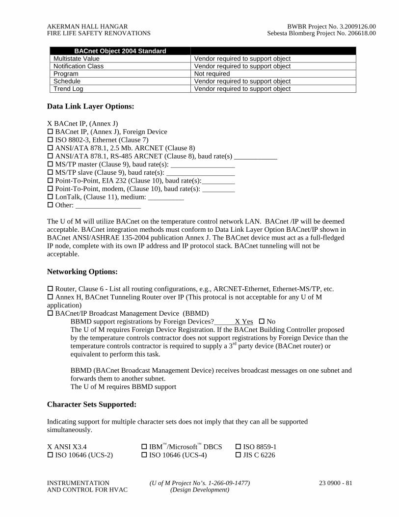
AKERMAN HALL HANGAR BWBR Project No. 3.2009126.00FIRE LIFE SAFETY RENOVATIONS Sebesta Blomberg Project No. 206618.00
INSTRUMENTATION (U of M Project No’s. 1-266-09-1477) 23 0900 - 81AND CONTROL FOR HVAC (Design Development)
BACnet Object 2004 StandardMultistate Value Vendor required to support objectNotification Class Vendor required to support objectProgram Not requiredSchedule Vendor required to support objectTrend Log Vendor required to support object
Data Link Layer Options:
X BACnet IP, (Annex J) BACnet IP, (Annex J), Foreign Device ISO 8802-3, Ethernet (Clause 7) ANSI/ATA 878.1, 2.5 Mb. ARCNET (Clause 8) ANSI/ATA 878.1, RS-485 ARCNET (Clause 8), baud rate(s) ____________MS/TP master (Clause 9), baud rate(s):MS/TP slave (Clause 9), baud rate(s): Point-To-Point, EIA 232 (Clause 10), baud rate(s): Point-To-Point, modem, (Clause 10), baud rate(s): LonTalk, (Clause 11), medium: __________ Other:
The U of M will utilize BACnet on the temperature control network LAN. BACnet /IP will be deemedacceptable. BACnet integration methods must conform to Data Link Layer Option BACnet/IP shown inBACnet ANSI/ASHRAE 135-2004 publication Annex J. The BACnet device must act as a full-fledgedIP node, complete with its own IP address and IP protocol stack. BACnet tunneling will not beacceptable.
Networking Options:
Router, Clause 6 - List all routing configurations, e.g., ARCNET-Ethernet, Ethernet-MS/TP, etc. Annex H, BACnet Tunneling Router over IP (This protocal is not acceptable for any U of Mapplication) BACnet/IP Broadcast Management Device (BBMD)
BBMD support registrations by Foreign Devices? X Yes NoThe U of M requires Foreign Device Registration. If the BACnet Building Controller proposedby the temperature controls contractor does not support registrations by Foreign Device than thetemperature controls contractor is required to supply a 3rd party device (BACnet router) orequivalent to perform this task.
BBMD (BACnet Broadcast Management Device) receives broadcast messages on one subnet andforwards them to another subnet.The U of M requires BBMD support
Character Sets Supported:
Indicating support for multiple character sets does not imply that they can all be supportedsimultaneously.
X ANSI X3.4 IBM/Microsoft DBCS ISO 8859-1 ISO 10646 (UCS-2) ISO 10646 (UCS-4) JIS C 6226

AKERMAN HALL HANGAR BWBR Project No. 3.2009126.00FIRE LIFE SAFETY RENOVATIONS Sebesta Blomberg Project No. 206618.00
INSTRUMENTATION (U of M Project No’s. 1-266-09-1477) 23 0900 - 82AND CONTROL FOR HVAC (Design Development)
The U of M requires ANSI X3.4 Support
All ANSI/ASHRA 135-2004 required standard object properties will be supported by the temperaturecontrols contractor BACnet device(s). Standard object optional properties will be supported if they are arequirement of any object listed above. Unsolicited change-of-value notification is required. All objectsand object properties will be supported so that alarms are sent from the temperature control contractorsBACnet building controller without having to be solicited from the U of M Master BACnet OperatorsWorkstation (B-OWS) or Master History PC.

AKERMAN HALL HANGAR BWBR Project No. 3.2009126.00FIRE LIFE SAFETY RENOVATIONS Sebesta Blomberg Project No. 206618.00
INSTRUMENTATION (U of M Project No’s. 1-266-09-1477) 23 0900 - 83AND CONTROL FOR HVAC (Design Development)
APPENDIX B: University Alarm Standards
Contact Energy Management for the latest standards.

AKERMAN HALL HANGAR BWBR Project No. 3.2009126.00FIRE LIFE SAFETY RENOVATIONS Sebesta Blomberg Project No. 206618.00
INSTRUMENTATION (U of M Project No’s. 1-266-09-1477) 23 0900 - 84AND CONTROL FOR HVAC (Design Development)
APPENDIX C: University Point Naming Conventions
Contact Energy Management for the latest point naming conventions.
AKERMAN HALL HANGAR BWBR Project No. 3.2009126.00FIRE LIFE SAFETY RENOVATIONS Sebesta Blomberg Project No. 206618.00
INSTRUMENTATION (U of M Project No’s. 1-266-09-1477) 23 0900 - 85AND CONTROL FOR HVAC (Design Development)
APPENDIX D: DUST, CONTAMINANT AND ODOR CONTROL OPTIONS
Construction related dust, contaminants and odors can cause significant problems for University studentsand staff, which disrupt normal University functions. This is particularly true in research and patientareas. Dust is not merely a nuisance, but can cause sensitive individuals to become ill and can damagescientific equipment or ruin experimental data. The A/E shall select from among the following types ofcontrols for projects to ensure that construction related dust, contaminants and odors do not migrate fromthe job site and disrupt normal University operations. Consult with the Owner's Representative andDEHS staff to select reasonable dust control measures that fit the situation.If construction is expected to affect several floors or a large area of the building, consider movingoccupants from that area until construction is completed.
The level of containment can be minimized if occupants are not present. Complaints from Universityemployees and exposures to construction dust and odors in adjacent occupied areas will be eliminated.Demolition and construction work can be completed without disruption due to repair of dust barriers andoccupant complaints.
Level 1 - Initial control options, which should be considered for all projects: Send a written notice to building occupants or other potentially affected individuals informing
them about the start of construction, expected noise, dust and/or odor issues, measures be takento control these issues, and expected ending date.
Close doors surrounding the construction. Install gaskets and door sweeps on doors. Evaluate supply/return duct system. Seal and/or filter return or exhaust ductwork as necessary to
isolate construction area. Wet materials during demolition so that visible emissions do no occur. Cover or wet materials being removed from job site. Use cutting tools to remove materials in large pieces. Do not use impact tools to demolish
materials. Sweep streets near job site frequently enough to prevent visible airborne emissions from
impacting normal University operations. Wet gravel and/or dirt driveways in construction area especially during dry periods that have
heavy traffic flow.
Level 2 - More extensive control options if Level 1 does not work or if project has special considerations: Seal around ductwork and pipes with plastic, tape, or caulk. Enclose work area with plastic sheets or sheet rock on the construction side of framing.
Enclosures must be continuous from the floor to the deck above. Seal joint perimeters with caulkor tape.
Protect doors and windows on adjacent buildings. Protect air intakes on adjacent buildings. Maintain airflow from clean areas to dirty areas on the job site. Provide fans or other ventilation
equipment to exhaust air from construction areas to the outside. Direct exhaust away frombuilding openings or air intakes.
Use exhaust devices on tools to capture dust at source. Remove construction debris in covered containers and in wet condition.
Level 3 - Additional measures for special projects involving sensitive patient and/or research areas: Fully enclose all work areas with sheet rock or plastic sheeting and seal joints or other openings
with caulk or tape. Create negative pressure for this enclosed work area by exhausting temporary

AKERMAN HALL HANGAR BWBR Project No. 3.2009126.00FIRE LIFE SAFETY RENOVATIONS Sebesta Blomberg Project No. 206618.00
INSTRUMENTATION (U of M Project No’s. 1-266-09-1477) 23 0900 - 86AND CONTROL FOR HVAC (Design Development)
ventilation from the work to the exterior. Periodically perform particle counts in clean areas and check airflow in adjacent areas to assure
that airflow direction is away from clean areas. Install air filtration equipment in occupied spaces adjacent to construction area. Have construction workers change into clean clothing and/or remove work shoes before entering
clean areas. Provide an area for workers to cleanup and change into clean clothing. Do not transport construction debris through clean areas. Schedule all work with the Owner's Representative to ensure that it has a minimal impact on
normal University operations. Work inside a glove bag. (Glove bags are typically used for asbestos abatement to control dust.
They could also be used for other small-scale activities in sensitive areas to control dustmigration).
End of Appendix A – Dust, Contaminant and Odor Control OptionsUniversity of Minnesota Facilities ManagementAugust 2000

AKERMAN HALL HANGAR BWBR Project No. 3.2009126.00FIRE LIFE SAFETY RENOVATIONS Sebesta Blomberg Project No. 206618.00
INSTRUMENTATION (U of M Project No’s. 1-266-09-1477) 23 0900 - 87AND CONTROL FOR HVAC (Design Development)
APPENDIX K: SECTION 13280 – HAZARDOUS MATERIALS PROCEDURES
Please refer to the University of Minnesota Construction Standards,APPENDIX K, Section 13280 – August 2000
(http://www.facm.umn.edu/cons/)

AKERMAN HALL HANGAR BWBR Project No. 3.2009126.00FIRE LIFE SAFETY RENOVATIONS Sebesta Blomberg Project No. 206618.00
HYDRONIC PIPING (U of M Project No’s. 1-266-09-1477) 23 2113 - 1(Design Development)
SECTION 23 2113
HYDRONIC PIPING
PART 1 - GENERAL
1.1 SUMMARY
A. This Section includes piping, special-duty valves, and hydronic specialties for chilled-water and hot-water systems.
1.2 SUBMITTALS
A. Product Data: For each type of special-duty valve indicated. Include flow and pressuredrop curves based on manufacturer's testing for diverting fittings, calibrated balancingvalves, and automatic flow-control valves.
B. Shop Drawings: Detail fabrication of pipe anchors, hangers, special pipe supportassemblies, alignment guides, expansion joints and loops, and their attachment to thebuilding structure. Detail location of anchors, alignment guides, and expansion joints andloops.
C. Welding Certificates: Copies of certificates for welding procedures and personnel.
D. Field Test Reports: Written reports of tests specified in Part 3 of this Section. Includethe following:
1. Test procedures used.
2. Test results that comply with requirements.
3. Failed test results and corrective action taken to achieve requirements.
E. Maintenance Data: For hydronic specialties and special-duty valves to include inmaintenance manuals specified in Division 1.
1.3 QUALITY ASSURANCE
A. Welding: Qualify processes and operators according to the ASME Boiler and PressureVessel Code: Section IX, "Welding and Brazing Qualifications."
B. ASME Compliance: Comply with ASME B31.9, "Building Services Piping," formaterials, products, and installation. Safety valves and pressure vessels shall bear theappropriate ASME label. Fabricate and stamp air separators and expansion tanks tocomply with the ASME Boiler and Pressure Vessel Code, Section VIII, Division 1.
1.4 COORDINATION
A. Coordinate layout and installation of hydronic piping and suspension system componentswith other construction.
B. Coordinate pipe sleeve installations for foundation wall penetrations.

AKERMAN HALL HANGAR BWBR Project No. 3.2009126.00FIRE LIFE SAFETY RENOVATIONS Sebesta Blomberg Project No. 206618.00
HYDRONIC PIPING (U of M Project No’s. 1-266-09-1477) 23 2113 - 2(Design Development)
C. Coordinate piping installation with roof curbs, equipment supports, and roof penetrations.
D. Coordinate pipe fitting pressure classes with products specified in related Sections.
E. Coordinate size and location of concrete bases. Cast anchor-bolt inserts into base.
F. Coordinate installation of pipe sleeves for penetrations through exterior walls and floorassemblies. Coordinate with requirements for firestopping specified in Division 7Section "Penetration Firestopping" for fire and smoke wall and floor assemblies.
PART 2 - PRODUCTS
2.1 MANUFACTURERS
A. Manufacturers: Subject to compliance with requirements, provide products by one of thefollowing:
1. Calibrated Balancing Valves:
a. Armstrong Pumps, Inc.
b. Flow Design, Inc.
c. Gerand Engineering Company.
d. Griswold Controls.
e. ITT Bell & Gossett; ITT Fluid Technology Corp.
f. Taco, Inc.
2. Pressure-Reducing Valves:
a. Amtrol, Inc.
b. Armstrong Pumps, Inc.
c. ITT Bell & Gossett; ITT Fluid Technology Corp.
d. Watts Industries, Inc.; Watts Regulators.
3. Safety Valves:
a. Amtrol, Inc.
b. Armstrong Pumps, Inc.
c. Conbraco Industries, Inc.
d. ITT McDonnell & Miller Div.; ITT Fluid Technology Corp.
4. Expansion Tanks:
a. Armstrong Pumps, Inc.
b. ITT Bell & Gossett; ITT Fluid Technology Corp.
c. Taco, Inc.
5. Air Separators and Air Purgers:
a. Armstrong Pumps, Inc.

AKERMAN HALL HANGAR BWBR Project No. 3.2009126.00FIRE LIFE SAFETY RENOVATIONS Sebesta Blomberg Project No. 206618.00
HYDRONIC PIPING (U of M Project No’s. 1-266-09-1477) 23 2113 - 3(Design Development)
b. ITT Bell & Gossett; ITT Fluid Technology Corp.
c. Taco, Inc.
2.2 PIPING MATERIALS
A. General: Refer to Part 3 "Piping Applications" Article for applications of pipe and fittingmaterials.
2.3 COPPER TUBE AND FITTINGS
A. Drawn-Temper Copper Tubing: ASTM B 88, Type K or L.
B. Wrought-Copper Fittings: ASME B16.22.
C. Wrought-Copper Unions: ASME B16.22.
D. Solder Filler Metals: ASTM B 32, 95-5 tin antimony.
E. Brazing Filler Metals: AWS A5.8, Classification BAg-1 (silver).
2.4 STEEL PIPE AND FITTINGS
A. Steel Pipe, NPS 2 and Smaller: ASTM A 53, Type S (seamless), Grade A, Schedule 40,black steel, plain ends.
B. Steel Pipe, NPS 2-1/2 through NPS 12: ASTM A 53, Type E or Type S Grade A.
C. Steel Pipe, NPS 14 through NPS 18: ASTM A 53, Type E or Type S Grade B.
D. Steel Pipe, NPS 20 and up: ASTM A 53, Type E or Type S Grade B .
1. Steel Pipe Nipples: ASTM A 733, made of ASTM A 53, Schedule 40, blacksteel; seamless for NPS 2 and smaller and electric-resistance welded for NPS 2-1/2 and larger.
E. Malleable-Iron Threaded Fittings: ASME B16.3, Classes 150 and 300.
F. Malleable-Iron Unions: ASME B16.39; Classes 150, 250, and 300.
G. Cast-Iron Pipe Flanges and Flanged Fittings: ASME B16.1, Classes 25, 125, and 250:raised ground face, and bolt holes spot faced.
H. Wrought-Steel Fittings: ASTM A 234, wall thickness to match adjoining pipe.
I. Wrought Cast- and Forged-Steel Flanges and Flanged Fittings: ASME B16.5, includingbolts, nuts, and gaskets of the following material group, end connections, and facings:
1. Material Group: 1.1.
2. End Connections: Butt welding.
3. Facings: Raised face.
4. Provide Isolation flanges at building entrances where shown on the drawings.
J. Flexible Connectors: Stainless-steel bellows with woven, flexible, bronze, wire-reinforcing protective jacket; 150-psig minimum working pressure and 250 deg F
AKERMAN HALL HANGAR BWBR Project No. 3.2009126.00FIRE LIFE SAFETY RENOVATIONS Sebesta Blomberg Project No. 206618.00
HYDRONIC PIPING (U of M Project No’s. 1-266-09-1477) 23 2113 - 4(Design Development)
maximum operating temperature. Connectors shall have flanged or threaded-endconnections to match equipment connected and shall be capable of 3/4-inchmisalignment.
K. Welding Materials: Comply with Section II, Part C, of the ASME Boiler and PressureVessel Code for welding materials appropriate for wall thickness and for chemicalanalysis of pipe being welded.
L. Gasket Material: Thickness, material, and type suitable for fluid to be handled; anddesign temperatures and pressures.
2.5 VALVES
A. Gate, globe, check, ball, and butterfly valves are specified in Division 23 Section "HVACGeneral Duty Valves."
B. Refer to Part 3 "Valve Applications" Article for applications of each valve.
C. Calibrated Balancing Valves, NPS 2 and Smaller: Bronze body, ball type, 125-psigworking pressure, 250 deg F maximum operating temperature, and having threaded ends.Valves shall have calibrated orifice or venturi, connections for portable differentialpressure meter with integral seals, and be equipped with a memory stop to retain setposition.
D. Calibrated Balancing Valves, NPS 2-1/2 and Larger: Cast-iron or steel body, ball type,125-psig working pressure, 250 deg F maximum operating temperature, and havingflanged or grooved connections. Valves shall have calibrated orifice or venturi,connections for portable differential pressure meter with integral seals, and be equippedwith a memory stop to retain set position.
E. Pressure-Reducing Valves: Diaphragm-operated, bronze or brass body with low inletpressure check valve, inlet strainer removable without system shutdown, andnoncorrosive valve seat and stem. Select valve size, capacity, and operating pressure tosuit system. Valve shall be factory set at operating pressure and have capability for fieldadjustment.
F. Safety Valves: Diaphragm-operated, bronze or brass body with brass and rubber, wetted,internal working parts; shall suit system pressure and heat capacity and shall comply withthe ASME Boiler and Pressure Vessel Code, Section IV.
2.6 SPECIALTIES
A. Manual Air Vent: Bronze body and nonferrous internal parts; 150-psig working pressure;225 deg F operating temperature; manually operated with screwdriver or thumbscrew;with NPS 1/8 discharge connection and NPS 1/2 inlet connection.
B. Automatic Air Vent: Designed to vent automatically with float principle; bronze bodyand nonferrous internal parts; 150-psig working pressure; 240 deg F operatingtemperature; with NPS 1/4 discharge connection and NPS 1/2 inlet connection.
C. Expansion Tanks: Welded carbon steel, rated for 125-psig working pressure and 375deg F maximum operating temperature. Separate air charge from system water tomaintain design expansion capacity by a flexible Butyl rubber bladder securely sealed

AKERMAN HALL HANGAR BWBR Project No. 3.2009126.00FIRE LIFE SAFETY RENOVATIONS Sebesta Blomberg Project No. 206618.00
HYDRONIC PIPING (U of M Project No’s. 1-266-09-1477) 23 2113 - 5(Design Development)
into tank. Include drain fitting and taps for pressure gage and air-charging fitting.Support vertical tanks with steel legs or base; support horizontal tanks with steel saddles.Factory fabricate and test tank with taps and supports installed and labeled according tothe ASME Boiler and Pressure Vessel Code, Section VIII, Division 1.
D. Tangential-Type Air Separators: Welded black steel; ASME constructed and labeled for125-psig minimum working pressure and 350 deg F maximum operating temperature;perforated stainless-steel air collector tube designed to direct released air into expansiontank; tangential inlet and outlet connections; threaded connections for NPS 2 and smaller;flanged connections for NPS 2-1/2 and larger; threaded blowdown connection. Provideunits in sizes for full-system flow capacity.
E. Y-Pattern Strainers: 125-psig working pressure; cast-iron body (ASTM A 126, Class B),flanged ends for NPS 2-1/2 and larger, threaded connections for NPS 2 and smaller,bolted cover, perforated stainless-steel basket, and bottom drain connection.
F. Stainless-steel bellow, flexible connectors: Stainless steel bellows with woven, flexible,bronze, wire-reinforcing protective jacket, 150 psig working pressure with threaded orflanged ends to match connected equipment. Connector shall be capable of ¾-inchmisalignment.
PART 3 - EXECUTION
3.1 PIPING APPLICATIONS
A. Hot Water Heating, NPS 2 and Smaller: Standard weight ASTM A53 or A120continuous weld black steel pipe with standard weight cast iron threaded fittings or TypeL copper with lead-free soldered joints.
B. Hot Water Heating, NPS 2-1/2 thru NPS 12: Standard weight ASTM A53 or A12Dcontinuous weld black steel pipe with welded fittings and 150 class weld NECX or slip-on flanges.
C. Chilled Water, Glycol and Heat Recovery, NPS 2 and smaller: Standard weight ASTMA53 or A120 continuous weld black steel pipe with standard weight cast iron threadedfittings.
D. Chilled water, Glycol and Heat Recovery, NPS 2-1/2 and larger: Standard weight ASTMA53 or A120 continuous weld black steel pipe with welded fittings and 150 class weldneck or slip-on flanges.
E. Chilled water, Glycol and Heat Recovery, NPS 2-1/2 and smaller: May be type K copperwith lead-free solder points.
3.2 VALVE APPLICATIONS
A. General-Duty Valve Applications: Unless otherwise indicated, use the following valvetypes:
1. Shutoff Duty: Gate, ball, and butterfly valves.
2. Throttling Duty: Butterfly valves.

AKERMAN HALL HANGAR BWBR Project No. 3.2009126.00FIRE LIFE SAFETY RENOVATIONS Sebesta Blomberg Project No. 206618.00
HYDRONIC PIPING (U of M Project No’s. 1-266-09-1477) 23 2113 - 6(Design Development)
B. Install shutoff duty valves at each branch connection to supply mains, at supplyconnection to each piece of equipment, unless only one piece of equipment is connectedin the branch line. Install throttling duty valves at each branch connection to returnmains, at return connections to each piece of equipment, and elsewhere as indicated.
C. Install check valves at each pump discharge and elsewhere as required to control flowdirection.
3.3 PIPING INSTALLATIONS.
A. Install groups of pipes parallel to each other, spaced to permit applying insulation andservicing of valves.
B. Install drains, consisting of a tee fitting, NPS 3/4 ball valve, and short NPS 3/4 threadednipple with cap, at low points in piping system mains and elsewhere as required forsystem drainage.
C. Install piping at a uniform grade of 0.2 percent upward in direction of flow.
D. Reduce pipe sizes using eccentric reducer fitting installed with level side up.
E. Unless otherwise indicated, install branch connections to mains using tee fittings in mainpipe, with the takeoff coming out the bottom of the main pipe. For up-feed risers, installthe takeoff coming out the top of the main pipe.
F. Install strainers on supply side of each pump and heat exchanger supply connections.Install NPS 3/4 nipple and ball valve in blowdown connection of strainers NPS 2 andlarger.
G. Anchor piping for proper direction of expansion and contraction.
3.4 HANGERS AND SUPPORTS
A. Hanger, support, and anchor devices are specified in Division 23 Section "HVACHangers and Supports.
3.5 PIPE JOINT CONSTRUCTION
A. Refer to Division 23 Section "HVAC Materials and Methods" for joint constructionrequirements for soldered and brazed joints in copper tubing; threaded, welded, andflanged joints in steel piping.
3.6 CORROSION PROTECTION
A. General
1. Install chilled water piping in accordance with the Drawings, this Specificationand approved submittals.
2. Provide electrical isolation for buried piping.
B. Field Wrapping and Coating of buried piping.
1. Field wrap and coat valves, fittings, bare pipe at welds, flanges, bolts, and otherbare metal after successful hydrostatic testing.

AKERMAN HALL HANGAR BWBR Project No. 3.2009126.00FIRE LIFE SAFETY RENOVATIONS Sebesta Blomberg Project No. 206618.00
HYDRONIC PIPING (U of M Project No’s. 1-266-09-1477) 23 2113 - 7(Design Development)
2. Tape coat pipe line tape or equal may be used for this purpose when selected andapplied in accordance with recommendations of manufacturer for the intendedservice.
3. Exercise proper caution to avoid damaging protective coatings/wraps. Repairany damaged coatings.
C. Electrical Inspection of Coatings
1. Contractor shall field inspect the entire cathodic protection system in thepresence of the Engineer and the Owner.
a. Establish and document that voltage between testing electrode andcoated metal structure is adequate for coating thickness and type ofcoating. Provide and demonstrate to the Engineer a sample of coatedpipe with a holiday of 1/8” diameter and show that the holiday detectorfunctions properly.
b. Establish and document that the ground system and coated metalstructure have minimum of electrical resistance between them.
c. Use holiday detector with audible alarm to signal spark jumping betweenelectrode and metal structure. Test in the presence of the cathodicsystem designer.
d. Provide complete checkout of coating system. Checkout shall becertified by contractor and system designer. Provide written report oftest results and certification of adequacy of system.
D. Installation of Cathodic Protection
1. Cathodic protection system installation includes installation of electrical work,wiring, fittings, anodes, bonding, thermite brazing and other work required for acomplete and functioning cathodic protection system.
2. Comply with anode location and spacing, pipe attachment method distance frompipe to anode, burial depth of anode and other applicable details of anodeinstallation as recommended by the cathodic protection system designer andsupplier.
3. Provide complete checkout of system. Checkout shall be certified by contractorand system designer. Provide written report of test results and certification ofadequacy of system.
3.7 HYDRONIC SPECIALTIES INSTALLATION
A. Install manual air vents at high points in piping and elsewhere as required for system airventing and ¾ NTP drains with hose bibs at all low points.
B. Install automatic air vents in mechanical equipment rooms only at high points of systempiping.
C. Install flexible connectors on suction and discharge of all pumps and equipment whereindicated on plans.

AKERMAN HALL HANGAR BWBR Project No. 3.2009126.00FIRE LIFE SAFETY RENOVATIONS Sebesta Blomberg Project No. 206618.00
HYDRONIC PIPING (U of M Project No’s. 1-266-09-1477) 23 2113 - 8(Design Development)
3.8 FIELD QUALITY CONTROL
A. Prepare piping according to ASME B31.9 and as follows:
1. Leave joints, including welds, uninsulated and exposed for examination duringtest.
2. Provide temporary restraints for expansion joints that cannot sustain reactionsdue to test pressure. If temporary restraints are impractical, isolate expansionjoints from testing.
3. Flush system with clean water. Clean strainers.
4. Isolate equipment from piping. If a valve is used to isolate equipment, its closureshall be capable of sealing against test pressure without damage to valve. Installblinds in flanged joints to isolate equipment.
5. Install safety valve, set at a pressure no more than one-third higher than testpressure, to protect against damage by expanding liquid or other source ofoverpressure during test.
B. Perform the following tests on piping:
1. Use ambient temperature water as a testing medium unless there is risk ofdamage due to freezing. Another liquid that is safe for workers and compatiblewith piping may be used.
2. While filling system, use vents installed at high points of system to releasetrapped air. Use drains installed at low points for complete draining of liquid.
3. Check expansion tanks to determine that they are not air bound and that system isfull of water.
4. Subject piping system to hydrostatic test pressure that is not less than 1.5 timesthe design pressure. Test pressure shall not exceed maximum pressure for anyvessel, pump, valve, or other component in system under test. Verify that stressdue to pressure at bottom of vertical runs does not exceed either 90 percent ofspecified minimum yield strength or 1.7 times "SE" value in Appendix A ofASME B31.9, "Building Services Piping."
5. After hydrostatic test pressure has been applied for at least 10 minutes, examinepiping, joints, and connections for leakage. Eliminate leaks by tightening,repairing, or replacing components, and repeat hydrostatic test until there are noleaks.
6. Prepare written report of testing.
3.9 CLEANING AND CHEMICAL PRETREATING
A. Cleaning and disinfecting shall be done by the university water treatment supplier, andincluded in the contractor’s bid. Coordinate cleaning and disinfecting operation with theuniversity zone personal. Disinfecting shall be done to meet the minimum requirementsthat DEHS defines.
B. Provide Minimum 2” temporary bypass piping at each building connection so that thenew piping can be cleaned, flushed and pre-treated with corrosion inhibitor. Corrosioninhibiting pre-treatment chemical shall not contact existing piping.

AKERMAN HALL HANGAR BWBR Project No. 3.2009126.00FIRE LIFE SAFETY RENOVATIONS Sebesta Blomberg Project No. 206618.00
HYDRONIC PIPING (U of M Project No’s. 1-266-09-1477) 23 2113 - 9(Design Development)
C. After hydrostatic testing, and prior to operational testing, thoroughly clean piping with acaustic soda, trisodium phosphate or equal chemical cleaner. Thoroughly flush pipingsystems with clean water. Remove and clean or replace strainer screens. After cleaningand flushing piping systems remove disposable fine-mesh strainers in pump suctiondiffusers. Provide documentation to the Owner that the new piping is cleaned and pre-treated and ready for use. After initial cleaning, the owner’s representative or designeeshall sign and certify that the system has been thoroughly cleaned.
D. Provide a temporary pot feeder connected to the new piping (if new piping is steel) foruse in chemical pre-treatment of the piping. Owner will furnish chemical (Nalco 2578)for pre-treatment. Coordinate with Owner’s chemical supplier and operators and providechemical pre-treatment in accordance with chemical supplier’s requirements.
E. Contractor may present to the Owner a plan to clean piping in the field prior to assemblyand to maintain Owner approved cleanliness of the piping throughout the constructionprocess. If the Owner approves such a plan the contractor may proceed. If it isdetermined that the interior of the chilled water piping is not properly clean, then theOwner may, at its discretion decide to require the contractor to perform the chemicalcleaning process in steps B and C above. Step D shall be performed regardless ofcleaning method.
END OF SECTION 23 2110

AKERMAN HALL HANGAR BWBR Project No. 3.2009126.00FIRE LIFE SAFETY RENOVATIONS Sebesta Blomberg Project No. 206618.00
HYDRONIC PUMPS (U of M Project No’s. 1-266-09-1477) 23 2123- 1(Design Development)
SECTION 23 2123
HYDRONIC PUMPS
PART 1 - GENERAL
1.1 RELATED DOCUMENTS
A. Drawings and general provisions of the Contract, including General and SupplementaryConditions and Division 1 Specification Sections, apply to this Section.
1.2 SUMMARY
A. This Section includes the following categories of hydronic pumps for hydronic systems:
1. In-line circulators.
2. Vertical in-line pumps.
3. End-suction pumps.
B. Related Sections include the following:
1. Division 23 Section "HVAC Motors" for general motor requirements.
2. Division 23 Section "HVAC Vibration Controls and Seismic Restraints" forinertia pads, isolation pads, spring supports, and spring hangers.
3. Division 26 Section “Variable-Frequency-Frequency Motor Controllers.
1.3 SUBMITTALS
A. Product Data: Include certified performance curves and rated capacities; shipping,installed, and operating weights; furnished specialties; final impeller dimensions; andaccessories for each type of product indicated. Indicate pump's operating point oncurves.
B. Shop Drawings: Show pump layout and connections. Include Setting Drawings withtemplates for installing foundation and anchor bolts and other anchorages.
1. Wiring Diagrams: Detail wiring for power, signal, and control systems anddifferentiate between manufacturer-installed and field-installed wiring.
C. Maintenance Data: For pumps to include in operation maintenance manuals specified inDivision 1.
1.4 QUALITY ASSURANCE
A. UL Compliance: Fabricate and label pumps to comply with UL 778, "Motor-OperatedWater Pumps," for construction requirements.
B. Product Options: Drawings indicate size, profiles, connections, and dimensionalrequirements of pumps and are based on the specific types and models indicated. Other

AKERMAN HALL HANGAR BWBR Project No. 3.2009126.00FIRE LIFE SAFETY RENOVATIONS Sebesta Blomberg Project No. 206618.00
HYDRONIC PUMPS (U of M Project No’s. 1-266-09-1477) 23 2123- 2(Design Development)
manufacturers' pumps with equal performance characteristics may be considered. Referto Division 1 Section "Substitution Procedures."
C. Electrical Components, Devices, and Accessories: Listed and labeled as defined inNFPA 70, Article 100, by a testing agency acceptable to authorities having jurisdiction.
1.5 DELIVERY, STORAGE, AND HANDLING
A. Manufacturer's Preparation for Shipping: Clean flanges and exposed machined metalsurfaces and treat with anticorrosion compound after assembly and testing. Protectflanges, pipe openings, and nozzles with wooden flange covers or with screwed-in plugs.
B. Store pumps in dry location.
C. Retain protective covers for flanges and protective coatings during storage.
D. Protect bearings and couplings against damage from sand, grit, and other foreign matter.
E. Comply with pump manufacturer's written rigging instructions.
1.6 COORDINATION
A. Coordinate size and location of concrete bases. Cast anchor-bolt inserts into bases.Concrete, reinforcement, and formwork requirements are specified in Division 3 Section"Cast-in-Place Concrete."
1.7 EXTRA MATERIALS
A. Furnish extra materials described below that match products installed and that arepackaged with protective covering for storage and identified with labels describingcontents.
1. Mechanical Seals: One mechanical seal for each pump.
PART 2 - PRODUCTS
2.1 MANUFACTURERS
A. Manufacturers: Subject to compliance with requirements, provide products by one of thefollowing:
1. In-Line Circulators:
a. Amtrol, Inc.
b. Armstrong Pumps, Inc.
c. Bell & Gossett ITT; Div. of ITT Fluid Technology Corp.
d. Taco; Fabricated Products Div.
2. Compact In-Line Circulators:
a. Amtrol, Inc.
b. Armstrong Pumps, Inc.
c. Bell & Gossett ITT; Div. of ITT Fluid Technology Corp.
AKERMAN HALL HANGAR BWBR Project No. 3.2009126.00FIRE LIFE SAFETY RENOVATIONS Sebesta Blomberg Project No. 206618.00
HYDRONIC PUMPS (U of M Project No’s. 1-266-09-1477) 23 2123- 3(Design Development)
d. Grundfos Pumps Corp.
e. PACO Pumps.
f. Taco; Fabricated Products Div.
3. Vertical In-Line Pumps:
a. Armstrong Pumps, Inc.
b. Bell & Gossett ITT; Div. of ITT Fluid Technology Corp.
c. Goulds Pumps, Inc.
d. Patterson Pump Co.
e. Peerless Pump Co.
f. Taco; Fabricated Products Div.
4. Flexible -Coupled, End-Suction Pumps:
a. Amtrol, Inc.
b. Armstrong Pumps, Inc.
c. Bell & Gossett ITT; Div. of ITT Fluid Technology Corp.
d. PACO Pumps.
e. Taco; Fabricated Products Div.
2.2 GENERAL PUMP REQUIREMENTS
A. Pump Units: Factory assembled and tested.
B. Motors: Include built-in, thermal-overload protection and grease-lubricated ballbearings. Select each motor to be nonoverloading over full range of pump performancecurve.
C. Motors Indicated to Be Energy Efficient: Minimum efficiency as indicated according toIEEE 112, Test Method B. Include motors with higher efficiency than "average standardindustry motors" according to IEEE 112, Test Method B, if efficiency is not indicated.
2.3 IN-LINE CIRCULATORS
A. Description: Horizontal, in-line, centrifugal, single-stage, bronze-fitted, radially splitcase design; rated for 125-psig minimum working pressure and a continuous watertemperature of 225 deg F.
1. Casing: Cast iron, with threaded companion flanges for piping connections, andthreaded gage tappings at inlet and outlet connections.
a. Connection Option: Unions at connections for casings that are notavailable with threaded companion flanges. Impeller: ASTM B 36,rolled-temper-brass fabrication, statically and dynamically balanced,closed, overhung, single suction, and keyed to shaft.
2. Shaft and Sleeve: Steel shaft with oil-lubricated copper sleeve.

AKERMAN HALL HANGAR BWBR Project No. 3.2009126.00FIRE LIFE SAFETY RENOVATIONS Sebesta Blomberg Project No. 206618.00
HYDRONIC PUMPS (U of M Project No’s. 1-266-09-1477) 23 2123- 4(Design Development)
3. Seals: Mechanical type. Include carbon-steel rotating ring, stainless-steel spring,ceramic seat, and flexible bellows and gasket.
4. Pump Bearings: Oil-lubricated, bronze journal and thrust type.
5. Motor Bearings: Oil-lubricated, sleeve type.
6. Coupling: Flexible, capable of absorbing torsional vibration and shaftmisalignment.
7. Motor: Resiliently mounted to pump casing.
2.4 COMPACT IN-LINE CIRCULATORS
A. Description: Cartridge type, horizontal, in-line, compact, seal-less, centrifugal, andsingle stage. Include pump and motor assembled on a common shaft in cartridge-type,hermetically sealed unit, without stuffing boxes or mechanical seals. Include isolation ofmotor section from motor-stator windings by corrosion-resistant, nonmagnetic, alloyliner. Include design rated for 125-psig minimum working pressure and a continuouswater temperature of 225 deg F.
1. Casing: Cast bronze or cast iron, with stainless-steel liner, static O-ring seal toseparate motor section from motor stator, and flanged piping connections.
2. Impeller: Overhung, single suction, closed or open, nonmetallic.
3. Shaft and Sleeve: Stainless-steel shaft with carbon-steel sleeve.
4. Motor: Single speed.
2.5 VERTICAL IN-LINE PUMPS
A. Description: Vertical, in-line, centrifugal, flexible-coupled, single-stage, radially splitcase design. Include vertical-mounting, bronze-fitted design and mechanical seals ratedfor 125-psig minimum working pressure and a continuous water temperature of225 deg F.
1. Casing: Cast iron, with threaded companion flanges for piping connectionssmaller than NPS 3, drain plug at low point of volute, and threaded gage tappingsat inlet and outlet connections.
2. Impeller: ASTM B 584, cast bronze, statically and dynamically balanced,closed, overhung, single suction, and keyed to shaft.
3. Wear Rings: Replaceable, bronze casing ring.
4. Shaft and Sleeve: Ground and polished stainless-steel shaft with bronze sleeve.
5. Shaft: Ground and polished stainless-steel shaft with axially split spacercoupling.
6. Seals: Mechanical, with carbon-steel rotating ring, stainless-steel spring, ceramicseat, and flexible bellows and gasket.
7. Motor: Directly mounted to pump casing and with lifting and supporting lugs intop of motor enclosure.
AKERMAN HALL HANGAR BWBR Project No. 3.2009126.00FIRE LIFE SAFETY RENOVATIONS Sebesta Blomberg Project No. 206618.00
HYDRONIC PUMPS (U of M Project No’s. 1-266-09-1477) 23 2123- 5(Design Development)
2.6 FLEXIBLE-COUPLED, END-SUCTION PUMPS
A. Description: Base-mounted, centrifugal, flexible-coupled, end-suction, single-stage,bronze-fitted, back-pull-out, radially split case design; rated for 175-psig minimumworking pressure and a continuous water temperature of 225 deg F.
1. Casing: Cast iron, with flanged piping connections, drain plug at low point ofvolute, threaded gage tappings at inlet and outlet connections, and integral feet orother means on volute to support weight of casing and attached piping. Casingshall allow removal and replacement of impeller without disconnecting piping.
2. Impeller: ASTM B 584, cast bronze, statically and dynamically balanced,closed, overhung, single suction, keyed to shaft, and secured by locking capscrew.
3. Wear Rings: Replaceable, bronze casing ring.
4. Shaft and Sleeve: Steel shaft with bronze sleeve.
5. Seals: Mechanical, with carbon-steel rotating ring, stainless-steel spring, ceramicseat, and flexible bellows and gasket.
6. Seals: Stuffing box, with at least four rings of graphite-impregnated braided yarnwith bronze lantern ring between center two graphite rings, and bronze packinggland.
7. Coupling: Flexible-spacer type, capable of absorbing torsional vibration andshaft misalignment; with flange and sleeve section that can be disassembled andremoved without removing pump or motor.
8. Coupling Guard: Steel, removable, and attached to mounting frame.
9. Mounting Frame: Welded-steel frame and cross members, factory fabricatedfrom ASTM A 36 channels and angles. Fabricate for mounting pump casing,coupling guard, and motor. Field-drill motor-mounting holes for field-installedmotors.
a. Option: Cast-iron frames are acceptable.
10. Motor: Secured to mounting frame, with adjustable alignment.
2.7 PUMP SPECIALTY FITTINGS
A. Suction Diffuser: Angle or straight pattern, 175-psig pressure rating, cast-iron body andend cap, pump-inlet fitting; with bronze startup and bronze or stainless-steel permanentstrainers; bronze or stainless-steel straightening vanes; drain plug; and factory- or field-fabricated support.
B. Triple-Duty Valve: Angle or straight pattern, 175-psig pressure rating, cast-iron body,pump-discharge fitting; with drain plug and bronze-fitted shutoff, balancing, and checkvalve features.

AKERMAN HALL HANGAR BWBR Project No. 3.2009126.00FIRE LIFE SAFETY RENOVATIONS Sebesta Blomberg Project No. 206618.00
HYDRONIC PUMPS (U of M Project No’s. 1-266-09-1477) 23 2123- 6(Design Development)
PART 3 - EXECUTION
3.1 EXAMINATION
A. Examine equipment foundations and anchor-bolt locations for compliance withrequirements for installation.
1. Examine roughing-in for piping systems to verify actual locations of pipingconnections before pump installation.
2. Examine foundations and inertia bases for suitable conditions where pumps areto be installed.
B. Proceed with installation only after unsatisfactory conditions have been corrected.
3.2 PUMP INSTALLATION
A. Install pumps according to manufacturer's written instructions.
1. Install pumps according to HI 1.1-1.5, "Centrifugal Pumps for Nomenclature,Definitions, Application and Operation."
B. Install pumps to provide access for periodic maintenance, including removing motors,impellers, couplings, and accessories.
C. Support pumps and piping separately so piping is not supported by pumps.
D. Suspend in-line pumps using continuous-thread hanger rod and vibration-isolationhangers.
E. Set base-mounted pumps on concrete foundation. Disconnect coupling halves beforesetting. Do not reconnect couplings until alignment operations have been completed.
1. Support pump baseplate on rectangular metal blocks and shims, or on metalwedges with small taper, at points near foundation bolts to provide a gap of 3/4 to1-1/2 inches between pump base and foundation for grouting.
2. Adjust metal supports or wedges until pump and driver shafts are level. Checkcoupling faces and suction and discharge flanges of pump to verify that they arelevel and plumb.
3.3 ALIGNMENT
A. Align pump and motor shafts and piping connections after setting them on foundations,after grout has been set and foundation bolts have been tightened, and after pipingconnections have been made.
B. Comply with pump and coupling manufacturers' written instructions.
C. Adjust pump and motor shafts for angular and offset alignment by methods specified inHI 1.1-1.5, "Centrifugal Pumps for Nomenclature, Definitions, Application andOperation."
D. After alignment is correct, tighten foundation bolts evenly but not too firmly.Completely fill baseplate with nonshrink, nonmetallic grout while metal blocks and shimsor wedges are in place. After grout has cured, fully tighten foundation bolts.

AKERMAN HALL HANGAR BWBR Project No. 3.2009126.00FIRE LIFE SAFETY RENOVATIONS Sebesta Blomberg Project No. 206618.00
HYDRONIC PUMPS (U of M Project No’s. 1-266-09-1477) 23 2123- 7(Design Development)
3.4 CONNECTIONS
A. Piping installation requirements are specified in other Division 23 Sections. Drawingsindicate general arrangement of piping, fittings, and specialties.
B. Install piping adjacent to machine to allow service and maintenance.
C. Connect piping to pumps. Install valves that are the same size as piping connected topumps.
D. Install suction and discharge pipe sizes equal to or greater than diameter of pump nozzles.
E. Install check valve and throttling valve on discharge side of in-line circulators.
F. Install nonslam check valve and globe valve on discharge side of vertical in-line pumps.
G. Install suction diffuser and shutoff valve on suction side of vertical in-line pumps.
H. Install triple-duty valve on discharge side of vertical in-line pumps.
I. Install suction diffuser and shutoff valve on suction side of base-mounted pumps.
J. Install triple-duty valve on discharge side of base-mounted pumps.
K. Install flexible connectors on suction and discharge sides of base-mounted pumpsbetween pump casing and valves.
L. Install pressure gages on pump suction and discharge. Install at integral pressure-gagetappings where provided.
M. Install temperature and pressure-gage connector plugs in suction and discharge pipingaround each pump.
N. Install electrical connections for power, controls, and devices.
O. Electrical power and control wiring and connections are specified in Division 26Sections.
P. Ground equipment.
1. Tighten electrical connectors and terminals according to manufacturer'spublished torque-tightening values. If manufacturer's torque values are notindicated, use those specified in UL 486A and UL 486B.
3.5 DEMONSTRATION
A. Engage a factory-authorized service representative to train Owner's maintenancepersonnel to adjust, operate, and maintain hydronic pumps as specified below:
1. Train Owner's maintenance personnel on procedures and schedules for startingand stopping, troubleshooting, servicing, and maintaining pumps.
2. Review data in maintenance manuals. Refer to Division 1 Section "CloseoutProcedures."
3. Review data in maintenance manuals. Refer to Division 1 Section "Operationand Maintenance Data."
AKERMAN HALL HANGAR BWBR Project No. 3.2009126.00FIRE LIFE SAFETY RENOVATIONS Sebesta Blomberg Project No. 206618.00
HYDRONIC PUMPS (U of M Project No’s. 1-266-09-1477) 23 2123- 8(Design Development)
4. Schedule training with Owner, through Architect, with at least seven days'advance notice.
END OF SECTION 23 2123

AKERMAN HALL HANGAR BWBR Project No. 3.2009126.00FIRE LIFE SAFETY RENOVATIONS Sebesta Blomberg Project No. 206618.00
STEAM AND CONDENSATE (U of M Project No’s. 1-266-09-1477) 23 22 13 - 1PIPING (Design Development)
SECTION 23 22 13
STEAM AND CONDENSATE PIPING
PART 1 - GENERAL
1.1 RELATED DOCUMENTS
A. Drawings and general provisions of the Contract, including General and SupplementaryConditions and Division 01 Specification Sections, apply to this Section.
1.2 SUMMARY
A. This Section includes the following for LP and HP steam and condensate piping:
1. Pipe and fittings.
2. Strainers.
3. Flash tanks.
4. Safety valves.
5. Steam traps.
6. Thermostatic air vents and vacuum breakers.
7. Steam and condensate meters.
1.3 DEFINITIONS
A. HP Systems: High-pressure piping operating at more than 15 psig as required byASME B31.1.
B. LP Systems: Low-pressure piping operating at 15 psig or less as required byASME B31.9.
1.4 PERFORMANCE REQUIREMENTS
A. Components and installation shall be capable of withstanding the following minimumworking pressures and temperatures:
1. LP Steam Piping: 75 psig and 350°F.
2. Condensate Piping: Equal to pressure and temperature of the piping system towhich it is attached.
3. Pumped Condensate Piping: 125 psig at 350°F.
4. Blowdown-Drain Piping: Equal to pressure and temperature of the piping systemto which it is attached.
5. Air-Vent and Vacuum-Breaker Piping: Equal to pressure and temperature of thepiping system to which it is attached.
6. Safety-Valve-Inlet and -Outlet Piping: Equal to pressure and temperature of thepiping system to which it is attached.
1.5 SUBMITTALS
A. Product Data: For each type of the following:
1. Strainer.

AKERMAN HALL HANGAR BWBR Project No. 3.2009126.00FIRE LIFE SAFETY RENOVATIONS Sebesta Blomberg Project No. 206618.00
STEAM AND CONDENSATE (U of M Project No’s. 1-266-09-1477) 23 22 13 - 2PIPING (Design Development)
2. Pressure-reducing and safety valve.
3. Steam trap.
4. Air vent and vacuum breaker.
5. Flash tank.
6. Meter.
B. Shop Drawings: Detail, flash tank assemblies and fabrication of pipe anchors, hangers,pipe, multiple pipes, alignment guides, and expansion joints and loops and theirattachment to the building structure. Detail locations of anchors, alignment guides, andexpansion joints and loops.
C. Qualification Data: For Installer.
D. Welding certificates.
E. Field quality-control test reports.
F. Operation and Maintenance Data: For valves, safety valves, pressure-reducing valves,steam traps, air vents, vacuum breakers, strainers and meters to include in emergency,operation, and maintenance manuals.
1.6 QUALITY ASSURANCE
A. Steel Support Welding: Qualify processes and operators according to AWS D1.1,"Structural Welding Code - Steel."
B. Pipe Welding: Qualify processes and operators according to the following:
1. Comply with provisions in ASME B31 Series, "Code for Pressure Piping."
2. Certify that each welder has passed AWS qualification tests for weldingprocesses involved and that certification is current.
C. Code Compliance: Comply with Minnesota Code for High Pressure Piping, Chapter5230, Minnesota Building Code Mechanical Systems Chapter 1345 ASME B31.1,"Power Piping" and ASME B31.9, "Building Services Piping" for materials, products,and installation. Safety valves and pressure vessels shall bear the appropriate ASMElabel. Fabricate and stamp flash tanks to comply with ASME Boiler and Pressure VesselCode: Section VIII, Division 1.
PART 2 - PRODUCTS
2.1 STEEL PIPE AND FITTINGS
A. Steel Pipe: ASTM A 53 or ASTM 106, black steel, plain ends, Type, Grade, andSchedule as indicated in Part 3 piping applications articles. Dimensions conforming toASME B36.10.
B. Malleable-Iron Threaded Fittings: ASME B16.3; Classes 150 and 300 as indicated inPart 3 piping application articles.
C. Forged Steel Threaded and Socket-Welding Fitting: ASME B16.11, MSS-SP-83, Classes2000, 3000 as indicated in Part 3 piping applications articles.
D. Wrought-Steel Welding Fittings: ASTM A 234 WPB Seamless, ASME B16.9, wallthickness to match adjoining pipe.

AKERMAN HALL HANGAR BWBR Project No. 3.2009126.00FIRE LIFE SAFETY RENOVATIONS Sebesta Blomberg Project No. 206618.00
STEAM AND CONDENSATE (U of M Project No’s. 1-266-09-1477) 23 22 13 - 3PIPING (Design Development)
E. Forged-Steel Flanges: ASME B16.5, of the following material end connections, andfacings:
1. Material: ASTM A105.
2. End Connections: Butt welding neck.
3. Facings: Raised face.
F. Steel Pipe Nipples: ASTM A 733, made of ASTM A 53 or ASTM A106, black steel ofsame Type, Grade, and Schedule as pipe in which installed.
G. Stainless-Steel Bellows, Flexible Connectors:
1. Body: Stainless-steel bellows with woven, flexible, bronze, wire-reinforced,protective jacket.
2. End Connections: Threaded or flanged to match equipment connected.
3. Performance: Capable of 3/4-inch misalignment.
4. CWP Rating: 250-psig.
5. Maximum Operating Temperature: 500 deg F.
2.2 JOINING MATERIALS
A. Pipe-Flange Gasket Materials: Suitable for chemical pressure and thermal conditions ofpiping system contents.
1. ASME B16.20 metallic, spiral-wound stainless steel and graphite, 1/8” thick.
B. ASTM A193 Gr. B7 Studs, ASTM A-194, Grade 2H heavy hex nuts; ASME B18.2.1 andASME B18.2.2.
C. Welding Materials: Comply with Section II, Part C, of ASME Boiler and PressureVessel Code for welding materials appropriate for wall thickness and for chemicalanalysis of pipe being welded.
2.3 DIELECTRIC FITTINGS
A. Description: Combination fitting of copper alloy and ferrous materials with threaded,solder-joint, plain, or weld-neck end connections that match piping system materials.
B. Insulating Material: Suitable for system fluid, pressure, and temperature.
C. Dielectric Unions:
1. Available Manufacturers: Subject to compliance with requirements,manufacturers offering products that may be incorporated into the Work include,but are not limited to, the following:
a. Capitol Manufacturing Company.
b. Central Plastics Company.
c. Hart Industries, International Inc.
d. Watts Water Technologies, Inc.
e. Zurn Plumbing Products Group.
2. Factory-fabricated union assembly, suitable for pressure and temperature ratingof joined system.
D. Dielectric Flanges:

AKERMAN HALL HANGAR BWBR Project No. 3.2009126.00FIRE LIFE SAFETY RENOVATIONS Sebesta Blomberg Project No. 206618.00
STEAM AND CONDENSATE (U of M Project No’s. 1-266-09-1477) 23 22 13 - 4PIPING (Design Development)
1. Available Manufacturers: Subject to compliance with requirements,manufacturers offering products that may be incorporated into the Work include,but are not limited to, the following:
a. Capitol Manufacturing Company.
b. Central Plastics Company.
c. Watts Water Technologies, Inc..
2. Factory-fabricated companion-flange assembly, for minimum working pressureand temperature as required to suit system requirements.
E. Dielectric-Flange Kits:
1. Available Manufacturers: Subject to compliance with requirements,manufacturers offering products that may be incorporated into the Work include,but are not limited to, the following:
a. Advance Products & Systems, Inc.
b. Calpico, Inc.
c. Central Plastics Company.
d. Pipeline Seal and Insulator, Inc.
2. Companion-flange assembly for field assembly. Include flanges, full-face- orring-type neoprene or phenolic gasket, phenolic or polyethylene bolt sleeves,phenolic washers, and steel backing washers.
3. Separate companion flanges and steel bolts and nuts shall have minimumworking pressure and temperature as required to suit system requirements.
2.4 VALVES
A. Quarter-Turn Rotary Process Valves
1. Quarter-Turn Rotary Process Valves, HP Systems:
a. Manufacturers:
(1) Tyco Valves & Controls, Vanessa Series 30,000 QTF
b. Body: Cast Steel ASTM A216 WCB
c. Body Style: double-flanged (ISO 5752 Table 1 Col. 13)
d. End Connections: ASME B16.5 Class 300
e. Seat: Stellite Gr. 21 weld overlay
f. Disc: ASTM A216 WCB nickel-plated
B. Gate Valves
1. Gate Valves, LP Systems, Up To and Including 2 Inches NPS:
a. Manufacturers:
(1) Bonney Forge, fig. W-11-T
b. Class: 800
c. Body: Forged steel
d. End Connections: threaded
e. Outside steam and yoke
f. Rising stem
g. Seat Rings: stainless steel

AKERMAN HALL HANGAR BWBR Project No. 3.2009126.00FIRE LIFE SAFETY RENOVATIONS Sebesta Blomberg Project No. 206618.00
STEAM AND CONDENSATE (U of M Project No’s. 1-266-09-1477) 23 22 13 - 5PIPING (Design Development)
h. Wedge: solid
i. Bonnet: threaded and seal welded
2. Gate Valves, LP Systems, 2 ½” Inches NPS and larger:
a. Manufacturers:
(1) Milwaukee Valve Company, model 1550
b. Class: 150
c. Body: cast steel
d. End Connections: butt weld
e. Outside steam and yoke
f. Rising stem
g. Seat Rings: stainless steel
h. Wedge: solid
C. Swing Check Valves
1. Swing Check Valves, LP Systems, up to and including 2 inches NPS:
a. Manufacturers:
(1) Milwaukee Valve Company, model 510
b. Class: 300
c. Body: bronze
d. End Connections: threaded
2. Swing Check Valves, LP Systems, over 2 inches NPS:
a. Manufacturer:
(1) Milwaukee Valve Company, model 1570
b. Class: 150
c. Body: cast steel
d. End Connections: flanged
e. Style: non-slam, replaceable disc
f. Bonnet: bolted
D. Globe Valves
1. Globe Valves, LP Systems, Up To and Including 2 Inches NPS:
a. Manufacturers:
(1) Bonney Forge, fig. W-30
b. Class: 800
c. Body: Forged steel
d. End Connections: threaded
e. Outside steam and yoke
f. Rising stem
g. Disc: stainless steel, loose, solid, integral backseat
h. Seat: stainless steel
i. Packing Gland: two-piece, self-aligning
j. Port: full

AKERMAN HALL HANGAR BWBR Project No. 3.2009126.00FIRE LIFE SAFETY RENOVATIONS Sebesta Blomberg Project No. 206618.00
STEAM AND CONDENSATE (U of M Project No’s. 1-266-09-1477) 23 22 13 - 6PIPING (Design Development)
k. Bonnet: threaded and seal welded
2. Globe Valves, LP Systems, 2 ½” Inches NPS and larger:
a. Manufacturers:
(1) Milwaukee Valve Company, model 1560
b. Class: 150
c. Body: cast steel
d. End Connections: butt weld
e. Outside steam and yoke
f. Rising stem
g. Seat: stainless steel
h. Disc: stainless steel
i. Bonnet: bolted
E. Piston Valves
1. Piston Valves:
a. Manufacturers:
(1) Klinger, model KVSN
b. Class: 300
c. Body: A216 WCB cast steel
d. End Connections: butt weld
2.5 STRAINERS
A. Y-Pattern Strainers; LP Systems:
1. Body: ASTM A 216, WCB steel.
2. End Connections: Threaded ends for strainers NPS 2and smaller; flanged endsfor strainers NPS 2-1/2and larger.
3. Strainer Screen: Brass, 20 mesh strainer.
4. Tapped blowoff plug.
5. ANSI Class 150.
2.6 FLASH TANKS
A. Shop or factory fabricated of welded steel according to ASME Boiler and PressureVessel Code, for 150-psig rating; and bearing ASME label. Fabricate with tappings forlow-pressure steam and condensate outlets, high-pressure condensate inlet, air vent,safety valve, and legs.
2.7 SAFETY VALVES
A. Cast-Iron Safety Valves (LP Systems):
1. Available Manufacturers: Subject to compliance with requirements,manufacturers offering products that may be incorporated into the Work include,but are not limited to, the following:
a. Armstrong International, Inc.
b. Kunkle Valve; a Tyco International Ltd. Company.
c. Spirax Sarco, Inc.

AKERMAN HALL HANGAR BWBR Project No. 3.2009126.00FIRE LIFE SAFETY RENOVATIONS Sebesta Blomberg Project No. 206618.00
STEAM AND CONDENSATE (U of M Project No’s. 1-266-09-1477) 23 22 13 - 7PIPING (Design Development)
d. Consolidated Value.
e. Watts Water Technologies, Inc.
2. Disc Material: Forged copper alloy with bronze nozzle.
3. End Connections: Raised-face flanged inlet and threaded or flanged outletconnections.
4. Spring: Fully enclosed cadmium-plated steel spring with adjustable pressurerange and positive shutoff, factory set and sealed.
5. Pressure Class: 250.
6. Drip-Pan Elbow: Cast iron and having threaded inlet, outlet, and drain, withthreads complying with ASME B1.20.1.
7. Exhaust Head: Cast iron and having threaded inlet and drain, with threadscomplying with ASME B1.20.1.
8. Size and Capacity: As required for equipment according to ASME Boiler andPressure Vessel Code.
2.8 STEAM TRAPS
A. Thermostatic Radiator Traps; LP System:
1. Available Manufacturers: Subject to compliance with requirements,manufacturers offering products that may be incorporated into the Work include,but are not limited to, the following:
a. Armstrong International, Inc.
b. Barnes & Jones, Inc.
c. Hoffman Specialty; Division of ITT Industries.
d. Spirax Sarco, Inc.
e. Sterling.
2. Body: Bronze angle-pattern body with integral union tailpiece and screw-in cap.
3. Trap Type: Balanced-pressure.
4. Bellows: Stainless steel or monel.
5. Head and Seat: Replaceable, hardened stainless steel.
6. Pressure Class: 125.
B. Thermostatic Traps:
1. Manufacturers: Subject to compliance with requirements, provide products byone of the following:
a. Armstrong International, Inc., Model AB-2000
b. Velan Inc., Model TS250
2. Body: Forged Steel.
3. End Connections: Threaded.
4. Disc and Seat: Stainless steel.
5. Maximum Operating Pressure: 250 psig @ 500ºF.
6. Type: Bi-metallic
7. Oriface: Minimum 3/8 inches.
C. Float and Thermostatic Traps, LP Systems:

AKERMAN HALL HANGAR BWBR Project No. 3.2009126.00FIRE LIFE SAFETY RENOVATIONS Sebesta Blomberg Project No. 206618.00
STEAM AND CONDENSATE (U of M Project No’s. 1-266-09-1477) 23 22 13 - 8PIPING (Design Development)
1. Manufacturers: Subject to compliance with requirements, provide products byone of the following:
a. Armstrong International, Inc.
2. Body and Bolted Cap: ASTM A 126, cast iron.
3. End Connections: Threaded.
4. Float Mechanism: Replaceable, stainless steel.
5. Head and Seat: Hardened stainless steel.
6. Trap Type: Balanced pressure.
7. Thermostatic Bellows: Stainless steel or monel.
8. Thermostatic air vent capable of withstanding 45 deg F of superheat and resistingwater hammer without sustaining damage.
9. Vacuum Breaker: Thermostatic with phosphor bronze bellows, and stainlesssteel cage, valve, and seat.
10. Maximum Operating Pressure: 125 psig.
D. Inverted Bucket Traps, LP Systems:
1. Manufacturers: Subject to compliance with requirements, provide products byone of the following:
a. Armstrong International, Inc., Series 880
2. Body and Cap: Cast iron.
3. End Connections: Threaded.
4. Head and Seat: Stainless steel.
5. Valve Retainer, Lever, and Guide Pin Assembly: Stainless steel.
6. Bucket: Brass or stainless steel.
7. Strainer: Integral stainless-steel inlet strainer within the trap body.
8. Air Vent: Stainless-steel thermostatic vent.
9. Pressure Rating: 150 psig.
2.9 THERMOSTATIC AIR VENTS AND VACUUM BREAKERS
A. Thermostatic Air Vents:
1. Available Manufacturers: Subject to compliance with requirements,manufacturers offering products that may be incorporated into the Work include,but are not limited to, the following:
a. Armstrong International, Inc.
b. Barnes & Jones, Inc.
c. Hoffman Specialty; Division of ITT Industries.
d. Spirax Sarco, Inc.
e. Sterling.
2. Body: Cast iron, bronze or stainless steel.
3. End Connections: Threaded.
4. Float, Valve, and Seat: Stainless steel.
5. Thermostatic Element: Phosphor bronze bellows in a stainless-steel cage.
6. Pressure Rating: 300 psig.
AKERMAN HALL HANGAR BWBR Project No. 3.2009126.00FIRE LIFE SAFETY RENOVATIONS Sebesta Blomberg Project No. 206618.00
STEAM AND CONDENSATE (U of M Project No’s. 1-266-09-1477) 23 22 13 - 9PIPING (Design Development)
7. Maximum Temperature Rating: 500 deg F.
8. Pressure and Temperature Rating: Equal to rating of piping system to which it isattached.
B. Vacuum Breakers:
1. Available Manufacturers: Subject to compliance with requirements,manufacturers offering products that may be incorporated into the Work include,but are not limited to, the following:
a. Armstrong International, Inc.
b. Hoffman Specialty; Division of ITT Industries.
c. Johnson Corporation (The).
d. Spirax Sarco, Inc.
2. Body: Cast iron, bronze, or stainless steel.
3. End Connections: Threaded.
4. Sealing Ball, Retainer, Spring, and Screen: Stainless steel.
5. O-ring Seal: EPR.
6. Pressure and Temperature Rating: Equal to rating of piping system to which it isattached.
2.10 STEAM METERS
A. Available Manufacturers: Subject to compliance with requirements, manufacturersoffering products that may be incorporated into the Work include, but are not limited to,the following:
1. EMCO Flow Systems; Division of Advanced Energy Company.
2. ISTEC Corp.
3. Preso Meters; a division of Racine Federated Inc.
4. Spirax Sarco, Inc.
B. Sierra Instruments, Inc.All steam meters shall be provided with remote surface-mountelectronic totalizers with two clearly identified terminals that allow for the remotereadout of consumption. One terminal shall have local readout and the other shall becapable of interfacing with the Building Automation System and BSAC to enable remotereading and data logging.
C. One remote readout terminal shall be a dry contact type, normally closed, and shall opento indicate a unit of measure. The contact shall be rated for at least two amps at 120volts. The contact shall remain open for at least 40 milliseconds. The other remotereadout terminal shall be 4 mA to 20 mA that is proportional to the flow rate. Thetotalizers shall be of a backlit LCD type, indicating steam flow and total, as manufacturedby Kessler Ellis.
D. Steam metering systems shall incorporate electronic “peak pickers” that can be reset andstore monthly peak flow.
E. Sensor: Vortex type with stainless-steel wetted parts and flange connections; and with apiezoelectric sensor removable and serviceable without shutting down the process. Atleast 40:1 turndown with plus or minus 1 percent accuracy over full-flow range.

AKERMAN HALL HANGAR BWBR Project No. 3.2009126.00FIRE LIFE SAFETY RENOVATIONS Sebesta Blomberg Project No. 206618.00
STEAM AND CONDENSATE (U of M Project No’s. 1-266-09-1477) 23 22 13 - 10PIPING (Design Development)
2.11 CONDENSATE METERS
A. Manufacturers: Subject to compliance with requirements, provide the following:
1. Niagara, WPX Series.
B. Body: Cast iron, bronze, or brass.
C. Rotor: Polyamid, polyetherether ketone.
D. Connections: Threaded for NPS 1 1/2 and smaller and flanged for NPS 2and larger.
E. Totalizer: Meters shall have a microprocessor to display flow, flow rate, time, and date;alarms for high and low flow rate, pressure, and temperature.
1. Computer shall have 4- to 20-mA or 2- to 10-volt output for temperature,pressure, and contact closure for flow increments.
2. Independent timers to store four peak flow rates and total flow.
3. Interface compatible with central workstation specified in Division 23 Section"Instrumentation and Control for HVAC."
4. Microprocessor Enclosure: NEMA 250, Type 4.
F. Pressure Rating and Temperature: Equal to rating of piping system to which it isattached.
2.12 PRESSURE REDUCING VALVES
A. Basis-of-Design Product: Subject to compliance with requirements, provide SpenceEngineering Co., Type E.
B. Size, Capacity, and Pressure Rating: Factory set for inlet and outlet pressures indicated.
C. Description: Pilot-actuated, diaphragm type, with adjustable pressure range and positiveshutoff.
D. Body: Cast steel, ASTM A216 WCB.
E. End Connections: Threaded connections for valves NPS 2 and smaller and flanged connectionsfor valves NPS 2-1/2 and larger.
F. Trim: Hardened stainless steel.
G. Head and Seat: Replaceable, main head stem guide fitted with flushing and pressure-arrestingdevice cover over pilot diaphragm.
H. Gaskets: Non-asbestos materials.
PART 3 - EXECUTION
3.1 LP STEAM PIPING APPLICATIONS
A. LP Steam Piping, NPS 2 and Smaller : Schedule 80, Type S, Grade B, steel pipe;Class 150 malleable-iron fittings; and threaded joints.

AKERMAN HALL HANGAR BWBR Project No. 3.2009126.00FIRE LIFE SAFETY RENOVATIONS Sebesta Blomberg Project No. 206618.00
STEAM AND CONDENSATE (U of M Project No’s. 1-266-09-1477) 23 22 13 - 11PIPING (Design Development)
B. LP Steam Piping, NPS 2-1/2 through NPS 12]: Schedule 40, Type S, Grade B, steel pipe;wrought steel fittings, Class 150 flanges, and flange fittings; and welded and flangedjoints.
C. LP Steam Piping, NPS 12 and Larger : Schedule 40 or STD, Type S, Grade B, steel pipe;Class 150 wrought-steel fittings, flanges, and flange fittings; and welded and flangedjoints.
D. Condensate piping, NPS 2 and Smaller: Schedule 80, Type S, Grade B, steel pipe;Class 2000 forged steel fittings; and threaded joints.
E. Condensate piping, NPS 2-1/2 and larger: Schedule 80, Type S, Grade B, steel pipe;wrought-steel fittings, flanges, and flange fittings; and welded and flanged joints.
3.2 ANCILLARY PIPING APPLICATIONS
A. Blowdown-Drain Piping: Same materials and joining methods as for piping specified forthe service in which blowdown drain is installed.
B. Air-Vent Piping:
1. Inlet: Same as service where installed.
2. Outlet: Type Kannealed-temper copper tubing with soldered or flared joints.
C. Vacuum-Breaker Piping: Outlet, same as service where installed.
D. Safety-Valve-Inlet and -Outlet Piping: Same materials and joining methods as for pipingspecified for the service in which safety valve is installed.
3.3 VALVE APPLICATIONS
A. All shutoff valves 3 inch NPS and larger on HP Steam Systems shall be installed with anexternal warm-up bypass line, including a globe valve and two pressure gauges.
B. For HP Steam Systems, unless noted otherwise on the drawings:
1. Use quarter-turn rotary process (Vanessa) valves on 3 inch NPS and larger forshut-off and to isolate equipment, parts of systems, or vertical risers;
2. Use gate valves on ½” to 2 ½ inch NPS for shut-off and to isolate equipment,parts of systems, or vertical risers;
3. Use globe valves for throttling, bypass, and manual flow control services;
4. Use piston valves for bypass of steam pressure control valves in pressurereducing station services.
C. For systems other than HP Steam, unless noted otherwise on the drawings:
1. use gate valves on for shut-off and to isolate equipment, parts of systems, orvertical risers;
2. use globe valves for throttling, bypass, and manual flow control services.
D. Install shutoff duty valves at branch connections to steam supply mains, at steam supplyconnections to equipment, and at the outlet of steam traps.
E. Install safety valves on pressure-reducing stations and elsewhere as required by ASMEBoiler and Pressure Vessel Code. Install safety-valve discharge piping, without valves,to nearest floor drain or as indicated on Drawings. Comply with ASME Boiler andPressure Vessel Code: Section VIII, Division 1, for installation requirements.

AKERMAN HALL HANGAR BWBR Project No. 3.2009126.00FIRE LIFE SAFETY RENOVATIONS Sebesta Blomberg Project No. 206618.00
STEAM AND CONDENSATE (U of M Project No’s. 1-266-09-1477) 23 22 13 - 12PIPING (Design Development)
3.4 PIPING INSTALLATION
A. Drawing plans, schematics, and diagrams indicate general location and arrangement ofpiping systems. Use indicated piping locations and arrangements if such were used tosize pipe and calculate friction loss, expansion, and other design considerations. Installpiping as indicated unless deviations to layout are approved on Coordination Drawings.
B. Install piping in concealed locations, unless otherwise indicated and except in equipmentrooms and service areas.
C. Install piping indicated to be exposed and piping in equipment rooms and service areas atright angles or parallel to building walls. Diagonal runs are prohibited unless specificallyindicated otherwise.
D. Install piping above accessible ceilings to allow sufficient space for ceiling panelremoval.
E. Install piping to permit valve servicing.
F. Install piping free of sags and bends.
G. Install fittings for changes in direction and branch connections.
H. Install piping to allow application of insulation.
I. Select system components with pressure rating equal to or greater than system operatingpressure.
J. Install groups of pipes parallel to each other, spaced to permit applying insulation andservicing of valves.
K. Install drains, consisting of a tee fitting, NPS 3/4full port-ball valve, and shortNPS 3/4threaded nipple with cap, at low points in piping system mains and elsewhere asrequired for system drainage.
L. Install steam supply piping at a minimum uniform grade of 0.2 percent downward indirection of steam flow.
M. Install condensate return piping at a minimum uniform grade of 0.4 percent downward indirection of condensate flow.
N. Reduce pipe sizes using eccentric reducer fitting installed with level side down.
O. Install branch connections to mains using mechanically formed tee fittings in main pipe,with the branch connected to top of main pipe. Branches 10 inch NPS and smaller inmains 2 or more nominal sizes larger than the branch and NPS 2 ½ inch or larger may usewelded branch connection fitting complying with MSS-SP-97 (Weld-O-let/Sock-O-let).
P. Install valves according to Division 23 Section "General-Duty Valves for HVAC Piping."
Q. Install unions in piping, NPS 2and smaller, adjacent to valves, at final connections ofequipment, and elsewhere as indicated.
R. Install flanges in piping, NPS 2-1/2and larger, at final connections of equipment andelsewhere as indicated.
S. Install strainers on supply side of control valves, pressure-reducing valves, traps, andelsewhere as indicated. Install NPS 3/4 nipple and full port ball valve in blowdownconnection of strainers NPS 3 and larger. Match size of strainer blowoff connection forstrainers smaller than NPS 3.

AKERMAN HALL HANGAR BWBR Project No. 3.2009126.00FIRE LIFE SAFETY RENOVATIONS Sebesta Blomberg Project No. 206618.00
STEAM AND CONDENSATE (U of M Project No’s. 1-266-09-1477) 23 22 13 - 13PIPING (Design Development)
T. Install expansion loops, expansion joints, anchors, and pipe alignment guides as specifiedin Division 23 Section "Expansion Fittings and Loops for HVAC Piping."
U. Identify piping as specified in Division 23 Section "Identification for HVAC Piping andEquipment."
V. Install drip legs at low points and natural drainage points such as ends of mains, bottomsof risers, and ahead of pressure regulators, and control valves.
1. On straight runs with no natural drainage points, install drip legs at intervals notexceeding 200 feet.
2. Size drip legs same size as main. In steam mains NPS and larger, drip leg sizecan be reduced, but to no less than NPS .
W. Flash Tank:
1. Pitch condensate piping down toward flash tank.
2. If more than one condensate pipe discharges into flash tank, install a check valvein each line.
3. Install thermostatic air vent at tank top.
4. Install safety valve at tank top.
5. Install gate valve, and swing check valve on condensate outlet.
6. Install inverted bucket or float and thermostatic trap at low-pressure condensateoutlet, sized for three times the calculated heat load.
X. Install sleeves for piping penetrations of walls, ceilings, and floors. Comply withrequirements for sleeves specified in Division 23 Section "Sleeves and Sleeve Seals forHVAC Piping."
Y. Install sleeve seals for piping penetrations of concrete walls and slabs. Comply withrequirements for sleeve seals specified in Division 23 Section "Sleeves and Sleeve Sealsfor HVAC Piping."
Z. Install escutcheons for piping penetrations of walls, ceilings, and floors. Comply withrequirements for escutcheons specified in Division 23 Section "Escutcheons for HVACPiping."
3.5 STEAM-TRAP INSTALLATION
A. Install steam traps in accessible locations as close as possible to connected equipment.
B. Install gate valve, strainer, and union upstream from trap; install union, drain, checkvalve, and gate valve downstream from trap unless otherwise indicated. Drain shallconsist of a tee fitting, gate valve, threaded nipple and cap.
3.6 PRESSURE REDUCING VALVE INSTALLATION
A. Install pressure-reducing valves in accessible location for maintenance and inspection.
B. Install bypass piping around pressure-reducing valves, with globe valve equal in size toarea of pressure-reducing valve seat ring, unless otherwise indicated.
C. Install gate valves on both sides of pressure-reducing valves.
D. Install unions or flanges on both sides of pressure-reducing valves having threaded- orflanged-end connections respectively.

AKERMAN HALL HANGAR BWBR Project No. 3.2009126.00FIRE LIFE SAFETY RENOVATIONS Sebesta Blomberg Project No. 206618.00
STEAM AND CONDENSATE (U of M Project No’s. 1-266-09-1477) 23 22 13 - 14PIPING (Design Development)
E. Install pressure gages on low-pressure side of pressure-reducing valves after the bypassconnection according to Division 23 Section "Meters and Gages for HVAC Piping."
F. Install strainers upstream for pressure-reducing valve.
G. Install safety valve downstream from pressure-reducing valve station.
3.7 STEAM OR CONDENSATE METER INSTALLATION
A. Install meters with lengths of straight pipe upstream and downstream according to steammeter manufacturer's instructions.
B. Provide data acquisition wiring. Refer to Division 23 Section "Instrumentation andControl for HVAC."
3.8 SAFETY VALVE INSTALLATION
A. Install safety valves according to ASME B31.1, "Power Piping" and ASME B31.9,"Building Services Piping."
B. Pipe safety-valve discharge without valves to atmosphere outside the building.
C. Install drip-pan elbow fitting adjacent to safety valve and pipe drain connection to nearestfloor drain.
D. Install exhaust head with drain to waste, on vents equal to or larger than NPS 2-1/2.
3.9 HANGERS AND SUPPORTS
A. Provide hangers and supports according to ASME B311." Comply with requirementsbelow for maximum spacing.
B. Install the following pipe attachments:
1. Adjustable steel clevis hangers for individual horizontal piping less than 20 feetlong.
2. Adjustable roller hangers and spring hangers for individual horizontal piping20 feet or longer.
3. Pipe Roller: MSS SP-58, Type 44 for multiple horizontal piping 20 feet orlonger, supported on a trapeze.
4. Spring hangers to support vertical runs.
C. Install hangers with the following maximum spacing and minimum rod sizes:
1. NPS 3/4: Maximum span, 9 feet; minimum rod size, 1/4 inch.
2. NPS 1: Maximum span, 9 feet; minimum rod size, 1/4 inch.
3. NPS 1-1/2: Maximum span, 12 feet; minimum rod size, 3/8 inch.
4. NPS 2: Maximum span, 13 feet; minimum rod size, 3/8 inch.
5. NPS 2-1/2: Maximum span, 14 feet; minimum rod size, 3/8 inch.
6. NPS 3: Maximum span, 15 feet; minimum rod size, 3/8 inch.
7. NPS 4: Maximum span, 17 feet; minimum rod size, 1/2 inch.
8. NPS 6: Maximum span, 21 feet; minimum rod size, 1/2 inch.
D. Install hangers for drawn-temper copper piping with the following maximum spacing andminimum rod sizes:
1. NPS 1/2: Maximum span, 4 feet; minimum rod size, 1/4 inch.
2. NPS 3/4: Maximum span, 5 feet; minimum rod size, 1/4 inch.

AKERMAN HALL HANGAR BWBR Project No. 3.2009126.00FIRE LIFE SAFETY RENOVATIONS Sebesta Blomberg Project No. 206618.00
STEAM AND CONDENSATE (U of M Project No’s. 1-266-09-1477) 23 22 13 - 15PIPING (Design Development)
3. NPS 1: Maximum span, 6 feet; minimum rod size, 1/4 inch.
4. NPS 1-1/2: Maximum span, 8 feet; minimum rod size, 3/8 inch.
5. NPS 2: Maximum span, 8 feet; minimum rod size, 3/8 inch.
6. NPS 2-1/2: Maximum span, 9 feet; minimum rod size, 3/8 inch.
7. NPS 3: Maximum span, 10 feet; minimum rod size, 3/8 inch.
E. Support vertical runs at roof, at each floor, and at 10-foot intervals between floors.
3.10 PIPE JOINT CONSTRUCTION
A. Join pipe and fittings according to the following requirements and Division 23 Sectionsspecifying piping systems.
B. Ream ends of pipes and tubes and remove burrs. Bevel plain ends of steel pipe.
C. Remove scale, slag, dirt, and debris from inside and outside of pipe and fittings beforeassembly.
D. Threaded Joints: Thread pipe with tapered pipe threads according to ASME B1.20.1.Cut threads full and clean using sharp dies. Ream threaded pipe ends to remove burrsand restore full ID. Join pipe fittings and valves as follows:
1. Apply appropriate tape or thread compound to external pipe threads unless dryseal threading is specified.
2. Damaged Threads: Do not use pipe or pipe fittings with threads that are corrodedor damaged. Do not use pipe sections that have cracked or open welds.
E. Welded Joints: Construct joints according to AWS D10.12, using qualified processes andwelding operators according to Part 1 "Quality Assurance" Article. All welding shall beperformed by a SMAW Prouss using approved electrodes. Root pass shall be performedwith AWS E6010 electrode without backing. Fill and cover passes shall be performedwith AWS E7018 electrode.
F. Flanged Joints: Select appropriate gasket material, size, type, and thickness for serviceapplication. Install gasket concentrically positioned. Use suitable lubricants on boltthreads.
3.11 TERMINAL EQUIPMENT CONNECTIONS
A. Size for supply and return piping connections shall be the same as or larger thanequipment connections.
B. Install traps and control valves in accessible locations close to connected equipment.
C. Install bypass piping with globe valve around control valve. If parallel control valves areinstalled, only one bypass is required.
D. Install vacuum breakers downstream from control valve, close to coil inlet connection.
E. Install a drip leg at coil outlet.
3.12 FIELD QUALITY CONTROL
A. A sample of HP system welds shall be examined by X-ray before hydrostatic testing.Engineer and Owner to determine sample number.
B. Prepare steam and condensate piping according to ASME B31.1, "Power Piping" andASME B31.9, "Building Services Piping," and as follows:
AKERMAN HALL HANGAR BWBR Project No. 3.2009126.00FIRE LIFE SAFETY RENOVATIONS Sebesta Blomberg Project No. 206618.00
STEAM AND CONDENSATE (U of M Project No’s. 1-266-09-1477) 23 22 13 - 16PIPING (Design Development)
1. Leave joints, including welds, uninsulated and exposed for examination duringtest.
2. Provide temporary restraints for expansion joints that cannot sustain reactionsdue to test pressure. If temporary restraints are impractical, isolate expansionjoints from testing.
3. Flush system with clean water. Clean strainers.
4. Isolate equipment from piping. If a valve is used to isolate equipment, its closureshall be capable of sealing against test pressure without damage to valve. Installblinds in flanged joints to isolate equipment.
5. Notify Owner at least 24 hours prior to testing. Proceed with testing only withwritten permission from owner.
C. Perform the following tests on steam and condensate piping:
1. Use ambient temperature water as a testing medium unless there is risk ofdamage due to freezing. Another liquid that is safe for workers and compatiblewith piping may be used.
2. Subject piping system to hydrostatic test pressure that is not less than 1.5 timesthe working pressure. Test pressure shall not exceed maximum pressure for anyvessel, pump, valve, or other component in system under test. Verify that stressdue to pressure at bottom of vertical runs does not exceed 90 percent of specifiedminimum yield strength.
3. After hydrostatic test pressure has been applied for at least 10 minutes, examinepiping, joints, and connections for leakage. Eliminate leaks by tightening,repairing, or replacing components, and repeat hydrostatic test until there are noleaks.
D. Prepare written report of testing.
END OF SECTION 232213

AKERMAN HALL HANGAR BWBR Project No. 3.2009126.00FIRE LIFE SAFETY RENOVATIONS Sebesta Blomberg Project No. 206618.00
HVAC WATER TREATMENT (U of M Project No’s. 1-266-09-1477) 23 2500- 1(Design Development)
SECTION 23 2500
HVAC WATER TREATMENT
PART 1 - GENERAL
1.1 RELATED DOCUMENTS
A. Drawings and general provisions of the Contract, including General and SupplementaryConditions and Division 1 Specification Sections, apply to this Section.
1.2 SUMMARY
A. This Section includes water-treatment systems for the following:
1. Heating, hot-water piping (closed-loop system).
2. Chilled-water piping (closed-loop system).
1.3 CHEMICAL FEED SYSTEM DESCRIPTION
A. Closed-Loop System: One bypass feeder on each system with isolating and drain valvesdownstream from circulating pumps, unless otherwise indicated.
1. Introduce chemical treatment through bypass feeder when required or indicatedby test.
1.4 PERFORMANCE REQUIREMENTS
A. Maintain water quality for HVAC systems that controls corrosion and build-up of scaleand biological growth for maximum efficiency of installed equipment without posing ahazard to operating personnel or the environment.
B. Base chemical treatment performance requirements on quality of water available atProject site, HVAC system equipment material characteristics and functionalperformance characteristics, operating personnel capabilities, and requirements andguidelines of authorities having jurisdiction.
1.5 SUBMITTALS
A. Product Data: Include rated capacities; water-pressure drops; shipping, installed, andoperating weights; and furnished products listed below:
1. Test equipment.
2. Chemicals.
3. Filters.
B. Shop Drawings: Detail equipment assemblies indicating dimensions, weights, loads,required clearances, method of field assembly, components, and location and size of eachfield connection.

AKERMAN HALL HANGAR BWBR Project No. 3.2009126.00FIRE LIFE SAFETY RENOVATIONS Sebesta Blomberg Project No. 206618.00
HVAC WATER TREATMENT (U of M Project No’s. 1-266-09-1477) 23 2500- 2(Design Development)
C. Water Analysis: Submit a copy of the water analysis to illustrate water quality availableat Project site.
D. Field Test Reports: Indicate and interpret test results for compliance with performancerequirements.
E. Maintenance Data: For pumps, agitators, filters, system controls, and accessories toinclude in maintenance manuals specified in Division 1.
1.6 QUALITY ASSURANCE
A. Installer Qualifications: An experienced installer who is an authorized representative ofthe chemical treatment manufacturer for both installation and maintenance of chemicaltreatment equipment required for this Project.
B. Electrical Components, Devices, and Accessories: Listed and labeled as defined inNFPA 70, Article 100, by a testing agency acceptable to authorities having jurisdiction,and marked for intended use.
1.7 MAINTENANCE
A. Scope of Service: Provide service program for maintaining optimum conditions in thecirculating water for inhibiting corrosion, scale, and organic growths in the [cooling,chilled-water piping] [heating, hot-water piping] and equipment. The University shallpurchase all chemicals necessary for chemical treatment of the systems. Services shall beprovided for a period of one year from date of Substantial Completion, including thefollowing:
1. Initial water analysis and recommendations.
2. Startup assistance.
3. Periodic field service and consultation.
4. Customer report charts and log sheets.
5. Laboratory technical assistance.
6. Analyses and reports of all chemical items concerning safety and compliancewith government regulations.
PART 2 - PRODUCTS
2.1 MANUFACTURERS
A. Manufacturers: Subject to compliance with requirements, provide products by one of thefollowing:
1. HVAC Water-Treatment Products:
a. Anderson Chemical Co., Inc.
b. DuBois Chemicals, Inc.; DuBois USA Subsidiary.
c. Nalco Chemical Co.

AKERMAN HALL HANGAR BWBR Project No. 3.2009126.00FIRE LIFE SAFETY RENOVATIONS Sebesta Blomberg Project No. 206618.00
HVAC WATER TREATMENT (U of M Project No’s. 1-266-09-1477) 23 2500- 3(Design Development)
2.2 CHEMICAL FEEDING EQUIPMENT
A. Bypass Feeders: Cast iron or steel, for introducing chemicals into system; with funnelshutoff valve on top, air-release valve on top, drain valve on bottom, and recirculatingshutoff valves on sides.
B. University of Minnesota Requirement: The minimum size of bypass feeder is 5 gallonsand shall be service rated for 300 psig per Division 15 section 15749 paragraph 2.1.2 ofthe 2002 Standards. Retain this section for University projects.
1. Capacity: 5 gal.
2. Working Pressure: 300 psig.
2.3 CHEMICALS
A. No chemicals are to be provided by the contractor. The University shall purchase allchemicals necessary for the chemical treatment of the system and turn over to thecontractor for introduction into the system.
B. System Cleaner: Liquid alkaline compound with emulsifying agents and detergents toremove grease and petroleum products.
PART 3 - EXECUTION
3.1 WATER ANALYSIS
A. Perform an analysis of supply water to determine the type and quantities of chemicaltreatment needed to maintain the water quality as specified in "PerformanceRequirements" Article.
3.2 INSTALLATION
A. Install treatment equipment level and plumb.
B. Add cleaning chemicals as recommended by manufacturer.
3.3 CONNECTIONS
A. Piping installation requirements are specified in other Division 23 Sections. Drawingsindicate general arrangement of piping, fittings, and specialties.
B. Install piping adjacent to equipment to allow service and maintenance.
3.4 FIELD QUALITY CONTROL
A. Engage a factory-authorized service representative to perform startup service.
1. Inspect field-assembled components and equipment installation, including pipingand electrical connections. Report results in writing.
2. Inspect piping and equipment to determine that systems and equipment havebeen cleaned, flushed, and filled with water, and are fully operational beforeintroducing chemicals for water-treatment system.

AKERMAN HALL HANGAR BWBR Project No. 3.2009126.00FIRE LIFE SAFETY RENOVATIONS Sebesta Blomberg Project No. 206618.00
HVAC WATER TREATMENT (U of M Project No’s. 1-266-09-1477) 23 2500- 4(Design Development)
END OF SECTION 23 2500

AKERMAN HALL HANGAR BWBR Project No. 3.2009126.00FIRE LIFE SAFETY RENOVATIONS Sebesta Blomberg Project No. 206618.00
METAL DUCTS (U of M Project No’s. 1-266-09-1477) 23 3113- 1(Design Development)
SECTION 23 3113
METAL DUCTS
PART 1 - GENERAL
1.1 RELATED DOCUMENTS
A. Drawings and general provisions of the Contract, including General and SupplementaryConditions and Division 1 Specification Sections, apply to this Section.
1.2 SUMMARY
A. This Section includes metal ducts for supply, return, outside, and exhaust air-distributionsystems in pressure classes from minus 2- to plus 10-inch wg. Metal ducts include thefollowing:
1. Single-wall, rectangular ducts and fittings.
2. Double-wall, rectangular ducts and fitting.
3. Single-wall, round, spiral-seam ducts and formed fittings.
4. Double-wall, round, spiral-seam ducts and formed fittings.
5. Duct liner.
B. Related Sections include the following:
1. Division 23 Section "HVAC Casings" for factory- and field-fabricated casingsfor mechanical equipment.
2. Division 23 Section "Duct Accessories" for dampers, sound-control devices,duct-mounting access doors and panels, turning vanes, and flexible ducts.
1.3 DEFINITIONS
A. FRP: Fiberglass-reinforced plastic.
1.4 SYSTEM DESCRIPTION
A. Duct system design, as indicated, has been used to select size and type of air-moving and-distribution equipment and other air system components. Changes to layout orconfiguration of duct system must be specifically approved in writing by Engineer.Accompany requests for layout modifications with calculations showing that proposedlayout will provide original design results without increasing system total pressure.
1.5 SUBMITTALS
A. Shop Drawings: Drawn to 1/4 inch equals 1 foot scale. Show fabrication and installationdetails for metal ducts.
1. Fabrication, assembly, and installation, including plans, elevations, sections,components, and attachments to other work.

AKERMAN HALL HANGAR BWBR Project No. 3.2009126.00FIRE LIFE SAFETY RENOVATIONS Sebesta Blomberg Project No. 206618.00
METAL DUCTS (U of M Project No’s. 1-266-09-1477) 23 3113- 2(Design Development)
2. Fittings.
3. Reinforcement and spacing.
4. Seam and joint construction.
5. Penetrations through fire-rated and other partitions.
6. Equipment installation based on equipment being used on Project.
7. Duct accessories, including access doors and panels.
8. Hangers and supports, including methods for duct and building attachment,vibration isolation, and seismic restraints.
B. Coordination Drawings: Reflected ceiling plans, drawn to scale, on which the followingitems are shown and coordinated with each other, based on input from installers of theitems involved:
1. Ceiling suspension assembly members.
2. Other systems installed in same space as ducts.
3. Ceiling- and wall-mounting access doors and panels required to provide access todampers and other operating devices.
4. Ceiling-mounting items, including lighting fixtures, diffusers, grilles, speakers,sprinklers, access panels, and special moldings.
C. Welding certificates.
D. Field quality-control test reports.
1.6 QUALITY ASSURANCE
A. Welding: Qualify procedures and personnel according to AWS D9.1, "Sheet MetalWelding Code," for duct joint and seam welding.
B. NFPA Compliance:
1. NFPA 90A, "Installation of Air Conditioning and Ventilating Systems."
2. NFPA 90B, "Installation of Warm Air Heating and Air Conditioning Systems."
PART 2 - PRODUCTS
2.1 MANUFACTURERS
A. In other Part 2 articles where titles below introduce lists, the following requirementsapply to product selection:
1. Manufacturers: Subject to compliance with requirements, provide products byone of the manufacturers specified.
2.2 SHEET METAL MATERIALS
A. Comply with SMACNA's "HVAC Duct Construction Standards--Metal and Flexible" foracceptable materials, material thicknesses, and duct construction methods, unless

AKERMAN HALL HANGAR BWBR Project No. 3.2009126.00FIRE LIFE SAFETY RENOVATIONS Sebesta Blomberg Project No. 206618.00
METAL DUCTS (U of M Project No’s. 1-266-09-1477) 23 3113- 3(Design Development)
otherwise indicated. Sheet metal materials shall be free of pitting, seam marks, rollermarks, stains, discolorations, and other imperfections.
B. Galvanized Sheet Steel: Lock-forming quality; complying with ASTM A 653/A 653Mand having G90 coating designation; ducts shall have mill-phosphatized finish forsurfaces exposed to view.
C. Reinforcement Shapes and Plates: Galvanized-steel reinforcement where installed ongalvanized sheet metal ducts.
D. Tie Rods: Galvanized steel, 1/4-inch minimum diameter for lengths 36 inches or less;3/8-inch minimum diameter for lengths longer than 36 inches.
2.3 DUCT LINER
A. Fibrous-Glass Liner: Comply with NFPA 90A or NFPA 90B and with NAIMA AH124.
1. Manufacturers:
(1) CertainTeed Corp.; Insulation Group.(2) Johns Manville International, Inc.(3) Knauf Fiber Glass GmbH.(4) Owens Corning.
2. Materials: ASTM C 1071; surfaces exposed to airstream shall be coated toprevent erosion of glass fibers.
(1) Thickness: 1 inch.(2) Thermal Conductivity (k-Value): 0.26 at 75 deg F mean
temperature.(3) Density: 3.0 lb(4) Fire-Hazard Classification: Maximum flame-spread index of 25
and smoke-developed index of 50 when tested according toASTM E 84.
(5) Liner Adhesive: Comply with NFPA 90A or NFPA 90B andwith ASTM C 916.
(6) Mechanical Fasteners: Galvanized steel suitable for adhesiveattachment, mechanical attachment, or welding attachment toduct without damaging liner when applied as recommended bymanufacturer and without causing leakage in duct.
(7) Tensile Strength: Indefinitely sustain a 50-lb tensile, dead-loadtest perpendicular to duct wall.
(8) Fastener Pin Length: As required for thickness of insulation andwithout projecting more than 1/8 inch into airstream.
(9) Adhesive for Attaching Mechanical Fasteners: Comply withfire-hazard classification of duct liner system.
2.4 SEALANT MATERIALS
A. Joint and Seam Sealants, General: The term "sealant" is not limited to materials ofadhesive or mastic nature but includes tapes and combinations of open-weave fabricstrips and mastics. UL listed, rated up to 10 inch pressure class.

AKERMAN HALL HANGAR BWBR Project No. 3.2009126.00FIRE LIFE SAFETY RENOVATIONS Sebesta Blomberg Project No. 206618.00
METAL DUCTS (U of M Project No’s. 1-266-09-1477) 23 3113- 4(Design Development)
1. Tape Sealing System: Woven-fiber tape impregnated with gypsum mineralcompound and modified acrylic/silicone activator to react exothermically withtape to form hard, durable, airtight seal.
2. Joint and Seam Sealant: One-part, nonsag, solvent-release-curing, polymerizedbutyl sealant formulated with a minimum of 75 percent solids.
3. Flanged Joint Mastic: One-part, acid-curing, silicone, elastomeric joint sealantcomplying with ASTM C 920, Type S, Grade NS, Class 25, Use O.
2.5 HANGERS AND SUPPORTS
A. Building Attachments: Concrete inserts, powder-actuated fasteners, or structural-steelfasteners appropriate for construction materials to which hangers are being attached.
1. Use powder-actuated concrete fasteners for standard-weight aggregate concretesor for slabs more than 4 inches thick.
2. Exception: Do not use powder-actuated concrete fasteners for lightweight-aggregate concretes or for slabs less than 4 inches thick.
B. Hanger Materials: Galvanized sheet steel or threaded steel rod.
1. Hangers Installed in Corrosive Atmospheres: Electrogalvanized, all-thread rodsor galvanized rods with threads painted with zinc-chromate primer afterinstallation.
2. Strap and Rod Sizes: Comply with SMACNA's "HVAC Duct ConstructionStandards--Metal and Flexible" for steel sheet width and thickness and for steelrod diameters.
C. Duct Attachments: Sheet metal screws, blind rivets, or self-tapping metal screws;compatible with duct materials.
D. Trapeze and Riser Supports: Steel shapes complying with ASTM A 36.
1. Supports for Galvanized-Steel Ducts: Galvanized-steel shapes and plates.
2.6 RECTANGULAR DUCT FABRICATION
A. Fabricate ducts, elbows, transitions, offsets, branch connections, and other constructionaccording to SMACNA's "HVAC Duct Construction Standards--Metal and Flexible" andcomplying with requirements for metal thickness, reinforcing types and intervals, tie-rodapplications, and joint types and intervals.
1. Lengths: Fabricate rectangular ducts in lengths appropriate to reinforcement andrigidity class required for pressure class.
2. Deflection: Duct systems shall not exceed deflection limits according toSMACNA's "HVAC Duct Construction Standards--Metal and Flexible."
B. Transverse Joints: Prefabricated slide-on joints and components constructed usingmanufacturer's guidelines for material thickness, reinforcement size and spacing, andjoint reinforcement.
1. Manufacturers:
AKERMAN HALL HANGAR BWBR Project No. 3.2009126.00FIRE LIFE SAFETY RENOVATIONS Sebesta Blomberg Project No. 206618.00
METAL DUCTS (U of M Project No’s. 1-266-09-1477) 23 3113- 5(Design Development)
a. Ductmate Industries, Inc.
b. Nexus Inc.
c. Ward Industries, Inc.
C. Formed-On Flanges: Construct according to SMACNA's "HVAC Duct ConstructionStandards--Metal and Flexible," Figure 1-4, using corner, bolt, cleat, and gasket details.
1. Manufacturers:
a. Ductmate Industries, Inc.
b. Lockformer.
c. Ward Industries, Inc.
2. Duct Size: Maximum 30 inches wide and up to 2-inch wg pressure class.
3. Longitudinal Seams: Pittsburgh lock sealed with noncuring polymer sealant.
D. Cross Breaking or Cross Beading: Cross break or cross bead duct sides 19 inches andlarger and 0.0359 inch thick or less, with more than 10 sq. ft. of nonbraced panel areaunless ducts are lined.
2.7 APPLICATION OF LINER IN RECTANGULAR DUCTS
A. Adhere a single layer of indicated thickness of duct liner with at least 90 percent adhesivecoverage at liner contact surface area. Attaining indicated thickness with multiple layersof duct liner is prohibited.
B. Apply adhesive to transverse edges of liner facing upstream that do not receive metalnosing.
C. Butt transverse joints without gaps and coat joint with adhesive.
D. Fold and compress liner in corners of rectangular ducts or cut and fit to ensure butted-edge overlapping.
E. Do not apply liner in rectangular ducts with longitudinal joints, except at corners of ducts,unless duct size and standard liner product dimensions make longitudinal jointsnecessary.
F. Secure liner with mechanical fasteners 4 inches from corners and at intervals notexceeding 12 inches transversely; at 3 inches from transverse joints and at intervals notexceeding 18 inches longitudinally.
G. Secure transversely oriented liner edges facing the airstream with metal nosings that haveeither channel or "Z" profiles or are integrally formed from duct wall. Fabricate edgefacings at the following locations:
1. Fan discharges.
2. Intervals of lined duct preceding unlined duct.
3. Upstream edges of transverse joints in ducts where air velocities are greater than2500 fpm or where indicated.
AKERMAN HALL HANGAR BWBR Project No. 3.2009126.00FIRE LIFE SAFETY RENOVATIONS Sebesta Blomberg Project No. 206618.00
METAL DUCTS (U of M Project No’s. 1-266-09-1477) 23 3113- 6(Design Development)
H. Terminate inner ducts with buildouts attached to fire-damper sleeves, dampers, turningvane assemblies, or other devices. Fabricated buildouts (metal hat sections) or otherbuildout means are optional; when used, secure buildouts to duct walls with bolts, screws,rivets, or welds.
2.8 ROUND AND FLAT-OVAL DUCT AND FITTING FABRICATION
A. Diameter as applied to flat-oval ducts in this Article is the diameter of a round duct with acircumference equal to the perimeter of a given size of flat-oval duct.
B. Round, Spiral Lock Seam Ducts: Fabricate supply ducts of galvanized steel according toSMACNA's "HVAC Duct Construction Standards--Metal and Flexible."
C. Flat-Oval, Spiral Lock Seam Ducts: Fabricate supply ducts according to SMACNA's"HVAC Duct Construction Standards--Metal and Flexible." Fabricate ducts larger than72 inches in diameter with butt-welded longitudinal seams.
1. Manufacturers:
a. McGill AirFlow Corporation.
b. SEMCO Incorporated.
c. Sheet Metal Connectors, Inc.
D. Duct Joints:
1. Ducts up to 20 Inches in Diameter: Interior, center-beaded slip coupling, sealedbefore and after fastening, attached with sheet metal screws.
2. Ducts 21 to 72 Inches in Diameter: Three-piece, gasketed, flanged jointconsisting of two internal flanges with sealant and one external closure band withgasket.
3. Ducts Larger Than 72 Inches in Diameter: Companion angle flanged joints perSMACNA "HVAC Duct Construction Standards--Metal and Flexible," Figure 3-2.
4. Round Ducts: Prefabricated connection system consisting of double-lipped,EPDM rubber gasket. Manufacture ducts according to connection systemmanufacturer's tolerances.
a. Manufacturers:
(1) Lindab Inc.(2) Engineer approved equal
5. Flat-Oval Ducts: Prefabricated connection system consisting of two flanges andone synthetic rubber gasket.
a. Manufacturers:
(1) Ductmate Industries, Inc.(2) McGill AirFlow Corporation.(3) SEMCO Incorporated.(4) Sheet Metal Connectors

AKERMAN HALL HANGAR BWBR Project No. 3.2009126.00FIRE LIFE SAFETY RENOVATIONS Sebesta Blomberg Project No. 206618.00
METAL DUCTS (U of M Project No’s. 1-266-09-1477) 23 3113- 7(Design Development)
E. 90-Degree Tees and Laterals and Conical Tees: Fabricate to comply with SMACNA's"HVAC Duct Construction Standards--Metal and Flexible," with metal thicknessesspecified for longitudinal-seam straight ducts.
F. Diverging-Flow Fittings: Fabricate with reduced entrance to branch taps and with noexcess material projecting from fitting onto branch tap entrance.
G. Fabricate elbows using die-formed, gored or pleated construction. Bend radius of die-formed, gored, and pleated elbows shall be 1-1/2 times duct diameter. Fabricate elbowsas follows:
1. Mitered-Elbow Radius and Number of Pieces: Welded construction complyingwith SMACNA's "HVAC Duct Construction Standards--Metal and Flexible,"unless otherwise indicated.
2. Round Elbows 8 Inches and Less in Diameter: Fabricate die-formed elbows for45- and 90-degree elbows and pleated elbows for 30, 45, 60, and 90 degrees only.Fabricate nonstandard bend-angle configurations or nonstandard diameter elbowswith gored construction.
3. Round Elbows 9 through 14 Inches in Diameter: Fabricate gored or pleatedelbows for 30, 45, 60, and 90 degrees. Fabricate nonstandard bend-angleconfigurations or nonstandard diameter elbows with gored construction.
4. Round Elbows Larger Than 14 Inches in Diameter and All Flat-Oval Elbows:Fabricate gored elbows.
5. Die-Formed Elbows for Sizes through 8 Inches in Diameter and All Pressures0.040 inch thick with 2-piece welded construction.
6. Round Gored-Elbow Metal Thickness: Same as non-elbow fittings specifiedabove.
7. Flat-Oval Elbow Metal Thickness: Same as longitudinal-seam flat-oval ductspecified above.
8. Pleated Elbows for Sizes through 14 Inches in Diameter and Pressures through10-Inch wg: 0.022 inch.
2.9 DOUBLE-WALL DUCT AND FITTING FABRICATION
A. Manufacturers:
1. Lindab Inc.
2. McGill AirFlow Corporation.
3. SEMCO Incorporated.
B. Ducts: Fabricate double-wall (insulated) ducts with an outer shell and an inner duct.Dimensions indicated are for inner ducts.
1. Outer Shell: Base metal thickness on outer-shell dimensions. Fabricate outer-shell lengths 2 inches longer than inner duct and insulation and in metal thicknessspecified for single-wall duct.
AKERMAN HALL HANGAR BWBR Project No. 3.2009126.00FIRE LIFE SAFETY RENOVATIONS Sebesta Blomberg Project No. 206618.00
METAL DUCTS (U of M Project No’s. 1-266-09-1477) 23 3113- 8(Design Development)
2. Insulation: 1-inch- thick fibrous glass liner as specified in this section.Terminate insulation where double-wall duct connects to single-wall duct oruninsulated components, and reduce outer shell diameter to inner duct diameter.
a. Thermal Conductivity (k-Value): 0.26 at 75 deg F mean temperature.
3. Solid Inner Ducts (Round): Use the following sheet metal thicknesses and seamconstruction for round ducts:
a. Ducts 3 to 8 Inches in Diameter: 0.019 inch with standard spiral-seamconstruction.
b. Ducts 9 to 42 Inches in Diameter: 0.019 inch with single-rib spiral-seamconstruction.
4. Solid Inner Ducts (Rectangular): Use the following sheet metal thicknesses forrectangular ducts:
a. Ducts up to 30 Inches in either dimension: 0.028 inch.
b. Ducts 31 to 60 Inches in either dimension: 0.034 inch.
c. Ducts 61 to 90 Inches in either dimension: 0.040 inch.
d. Ducts 91 Inches and greater in either dimension: 0.052 inch.
5. Perforated Inner Ducts: Fabricate with 0.028-inch thick sheet metal having 3/32-inch-diameter perforations, with overall open area of 23 percent. Cover theinsulation face behind the perforated inner duct with a NFPA 90A approvedsynthetic liner with a minimum thickness of 2-mil.
6. Maintain concentricity of inner duct to outer shell by mechanical means. Preventdislocation of insulation by mechanical means.
C. Fittings: Fabricate double-wall (insulated) fittings with an outer shell and an inner duct.
1. Solid Inner Ducts (Round): Use the following sheet metal thicknesses for roundducts:
a. Ducts 3 to 34 Inches in Diameter: 0.028 inch.
2. Solid Inner Ducts (Rectangular): Use the following sheet metal thicknesses forrectangular ducts:
a. Ducts up to 30 Inches in either dimension: 0.034 inch.
b. Ducts 31 to 60 Inches in either dimension: 0.040 inch.
c. Ducts 61 to 90 Inches in either dimension: 0.052 inch.
d. Ducts 91 Inches and greater in either dimension: 0.064 inch.
3. Perforated Inner Ducts: Fabricate with 0.028-inch-thick sheet metal having 3/32-inch- diameter perforations, with overall open area of 23 percent. Cover theinsulation face behind the perforated inner duct with a NFPA 90A approvedsynthetic liner with a minimum thickness of 2-mil.

AKERMAN HALL HANGAR BWBR Project No. 3.2009126.00FIRE LIFE SAFETY RENOVATIONS Sebesta Blomberg Project No. 206618.00
METAL DUCTS (U of M Project No’s. 1-266-09-1477) 23 3113- 9(Design Development)
PART 3 - EXECUTION
3.1 DUCT APPLICATIONS
A. Static-Pressure Classes: Unless otherwise indicated, construct ducts according to thefollowing schedule:
Table 3.1a Duct Construction Schedule:
SystemSMACNA Duct Pressure Class (Inches wg)
Supply Return Exhaust Outside AirNotes
Discharge Suction Discharge Suction Discharge Suction DischargeSUP-01 +3 -2 +2 - - -2 - 1Downstream of VAVs +2 - - - - - -
1. Supply pressure indicated is for ductwork upstream of the system terminal units.
B. Duct Sealing: Unless otherwise indicated, seal duct seams and joints according toSMACNA's "HVAC Duct Construction Standards--Metal and Flexible" as listed in table3.1b below for duct pressure class indicated.
1. If approved by the engineer, construction of joints and seams may deviate fromspecifications above in order to meet seal class requirements.
2. Seal ducts before external insulation is applied.
3. Ducts not requiring seam and joint sealing include:
(1) Ducts used to transfer air between ceiling plenums.
Table 3.1b Duct Sealing and Allowable Leakage Schedule:
Duct System
SMACNA Duct Seal and Leakage Class
Duty Rectangular Round Notes
Pos/Neg(in wg)
SealClass
Leakage Class (CL)(cfm/100 ft2 @ 1”wg)
SealClass
Leakage Class (CL)(cfm/100 ft2 @ 1”wg)
AHU Supply Pos. A 6 A 3AHU Return Neg C 24 C 12Downstream of VAV’s Pos. C 24 C 12
C. All ducts shall be galvanized steel except as follows:
1. Acid-Resistant (Fume-Handling) Ducts: Type 304, stainless-steel sheet withNo. 4 finish.
D. Seal duct seams and joints according to SMACNA's "HVAC Duct ConstructionStandards--Metal and Flexible" for duct pressure class indicated with the followingexceptions:
1. For pressure classes lower than 2-inch wg, seal transverse joints.
2. SMACNA Seal Class A is required for ducts concealed within shaft enclosures.
E. Seal ducts before external insulation is applied.
F. Ducts not requiring seam and joint sealing include:

AKERMAN HALL HANGAR BWBR Project No. 3.2009126.00FIRE LIFE SAFETY RENOVATIONS Sebesta Blomberg Project No. 206618.00
METAL DUCTS (U of M Project No’s. 1-266-09-1477) 23 3113- 10(Design Development)
1. Ducts used to transfer air between ceiling plenums.
3.2 DUCT INSTALLATION
A. Construct and install ducts according to SMACNA's "HVAC Duct ConstructionStandards--Metal and Flexible," unless otherwise indicated.
B. Construct return air plenum transfer ducts with 1 inch interior duct liner to increase theinsertion loss of the transfer duct.
C. Lined ductwork is only to be used in fabrication of plenum transfer ducts.
D. Install round and flat-oval ducts in lengths not less than 12 feet unless interrupted byfittings.
E. Install ducts with fewest possible joints.
F. Install fabricated fittings for changes in directions, size, and shape and for connections.
G. Install couplings tight to duct wall surface with a minimum of projections into duct.Secure couplings with sheet metal screws. Install screws at intervals of 12 inches, with aminimum of 3 screws in each coupling.
H. Install ducts, unless otherwise indicated, vertically and horizontally and parallel andperpendicular to building lines; avoid diagonal runs.
I. Install ducts close to walls, overhead construction, columns, and other structural andpermanent enclosure elements of building.
J. Install ducts with a clearance of 1 inch, plus allowance for insulation thickness.
K. Conceal ducts from view in finished spaces. Do not encase horizontal runs in solidpartitions unless specifically indicated.
L. Coordinate layout with suspended ceiling, fire- and smoke-control dampers, lightinglayouts, and similar finished work.
M. Seal all joints and seams. Apply sealant to male end connectors before insertion, andafterward to cover entire joint and sheet metal screws.
N. Non-Fire-Rated Partition Penetrations: Where ducts pass through interior partitions andexterior walls and are exposed to view, conceal spaces between construction openingsand ducts or duct insulation with sheet metal flanges of same metal thickness as ducts.Overlap openings on 4 sides by at least 1-1/2 inches.
O. Fire-Rated Partition Penetrations: Where ducts pass through interior partitions andexterior walls, install appropriately rated fire dampers, sleeves, and firestopping sealant.Fire and smoke dampers are specified in Division 15 Section "Duct Accessories."Firestopping materials and installation methods are specified in Division 7 Section"Through-Penetration Firestop Systems."
P. Protect duct interiors from the elements and foreign materials until building is enclosed.Follow SMACNA's "Duct Cleanliness for New Construction."

AKERMAN HALL HANGAR BWBR Project No. 3.2009126.00FIRE LIFE SAFETY RENOVATIONS Sebesta Blomberg Project No. 206618.00
METAL DUCTS (U of M Project No’s. 1-266-09-1477) 23 3113- 11(Design Development)
3.3 HANGING AND SUPPORTING
A. Support horizontal ducts within 24 inches of each elbow and within 48 inches of eachbranch intersection.
B. Support vertical ducts at maximum intervals of 16 feet and at each floor.
C. Install upper attachments to structures with an allowable load not exceeding one-fourth offailure (proof-test) load.
D. Install concrete inserts before placing concrete.
E. Install powder-actuated concrete fasteners after concrete is placed and completely cured.
1. Do not use powder-actuated concrete fasteners for lightweight-aggregateconcretes or for slabs less than 4 inches thick.
3.4 CONNECTIONS
A. Make connections to equipment with flexible connectors according to Division 15Section "Duct Accessories."
B. Comply with SMACNA's "HVAC Duct Construction Standards--Metal and Flexible" forbranch, outlet and inlet, and terminal unit connections.
3.5 AIR DUCT LEAKAGE TESTING
A. Field tests and inspections shall be performed according to SMACNA's "HVAC Air DuctLeakage Test Manual".
1. Contractor shall, after installation and prior to insulating, leak test arepresentative sample of the following duct systems.
(1) Supply air ductwork upstream of reheat coils.
2. Contractor shall notify the Engineer upon completion of duct installationselection of representative test samples. Each sample specimen shall be selectedby the Engineer prior to testing and include at least five transverse joints, typicalseams, an access door, an elbow and at least two typical branch connections.
3. Once representative test samples are selected, contractor shall notify partieswhose presence is necessary for the test; and in all cases, the Engineer andOwner’s project manager at least two days' in advance of testing.
4. The contractor shall disassemble, reassemble, and cap segments of systems toaccommodate leakage testing and for compliance with test requirements.
(1) With the exception of end cap sealing, field application of jointsealant shall not be applied to the test sample prior to the leaktest.
5. Tests shall be conducted at static pressures equal to maximum design pressure ofsystem or section being tested. Do not pressurize systems above maximumdesign operating pressure.
6. The leakage amount shall not exceed the allowed amount for the pressure class orthe allotted amount for that portion of the system, whichever is applicable. Themaximum allowable leakage shall be as listed in table 3.1b above.

AKERMAN HALL HANGAR BWBR Project No. 3.2009126.00FIRE LIFE SAFETY RENOVATIONS Sebesta Blomberg Project No. 206618.00
METAL DUCTS (U of M Project No’s. 1-266-09-1477) 23 3113- 12(Design Development)
7. While system is under pressure, survey joints for audible leaks. Mark leakagepoints, shut down blower and make repairs. Retest after duct sealant has dried orcured.
B. If any specimen fails to meet allowable leakage level, the following requirements shallapply.
1. The contractor shall modify the representative sample to bring into complianceand shall retest it until leakage is equal to or less than the maximum allowable.
2. Another representative sample will be selected at random for leak testing andshall be tested as outlined above.
3. Additional costs due to testing and remediation shall be the responsibility of thecontractor.
C. All tests and necessary repairs shall be completed prior to the insulation and concealmentof ducts.
D. The contactor shall prepare test reports according to SMACNA's "HVAC Air DuctLeakage Test Manual" and submit to the Engineer for the record.
END OF SECTION 23 3113

AKERMAN HALL HANGAR BWBR Project No. 3.2009126.00FIRE LIFE SAFETY RENOVATIONS Sebesta Blomberg Project No. 206618.00
DUCTWORK ACCESSORIES (U of M Project No’s. 1-266-09-1477) 23 3300- 1(Design Development)
SECTION 23 3300
DUCTWORK ACCESSORIES
PART 1 - GENERAL
1.1 RELATED DOCUMENTS
A. Drawings and general provisions of the Contract, including General and SupplementaryConditions and Division 1 Specification Sections, apply to this Section.
1.2 SUMMARY
A. This Section includes the following:
1. Backdraft dampers.
2. Volume dampers.
3. Fire dampers.
4. Ceiling fire dampers.
5. Smoke dampers.
6. Combination fire and smoke dampers.
7. Duct silencers.
8. Turning vanes.
9. Duct-mounted access doors.
10. Flexible connectors.
11. Flexible ducts.
12. Spin-in fittings with integral balancing dampers.
13. Duct accessory hardware.
B. Related Sections include the following:
1. Division 28 Section "Fire Alarm" for duct-mounting fire and smoke detectors.
2. Division 23 Section "HVAC Instrumentation and Controls" for damper actuators.
1.3 SUBMITTALS
A. Product Data: For the following:
1. Backdraft dampers.
2. Volume dampers.
3. Fire dampers.
4. Ceiling fire dampers.
5. Smoke dampers.
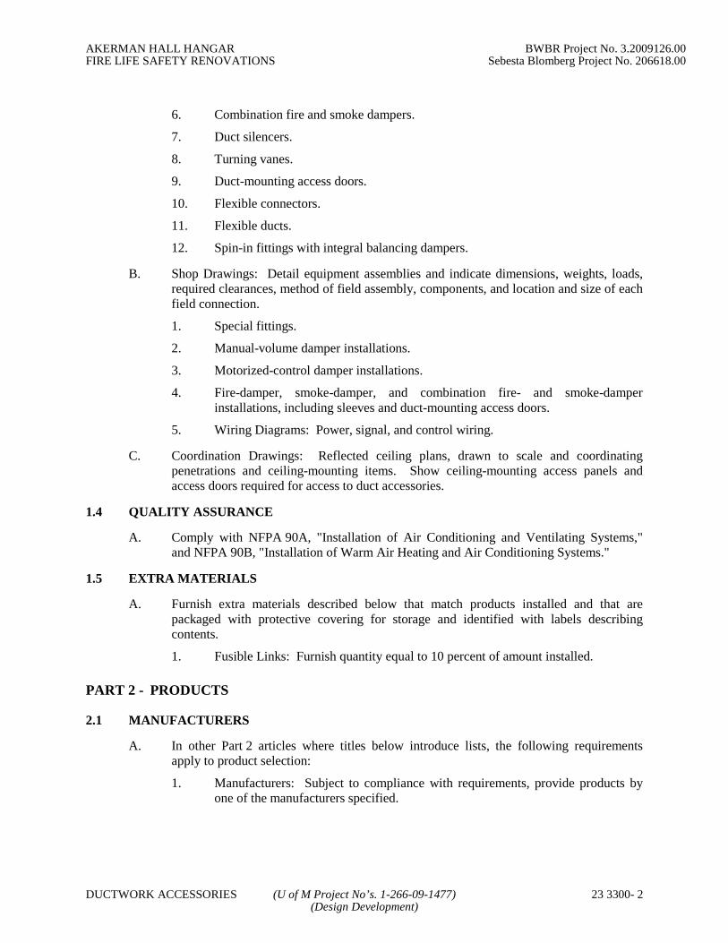
AKERMAN HALL HANGAR BWBR Project No. 3.2009126.00FIRE LIFE SAFETY RENOVATIONS Sebesta Blomberg Project No. 206618.00
DUCTWORK ACCESSORIES (U of M Project No’s. 1-266-09-1477) 23 3300- 2(Design Development)
6. Combination fire and smoke dampers.
7. Duct silencers.
8. Turning vanes.
9. Duct-mounting access doors.
10. Flexible connectors.
11. Flexible ducts.
12. Spin-in fittings with integral balancing dampers.
B. Shop Drawings: Detail equipment assemblies and indicate dimensions, weights, loads,required clearances, method of field assembly, components, and location and size of eachfield connection.
1. Special fittings.
2. Manual-volume damper installations.
3. Motorized-control damper installations.
4. Fire-damper, smoke-damper, and combination fire- and smoke-damperinstallations, including sleeves and duct-mounting access doors.
5. Wiring Diagrams: Power, signal, and control wiring.
C. Coordination Drawings: Reflected ceiling plans, drawn to scale and coordinatingpenetrations and ceiling-mounting items. Show ceiling-mounting access panels andaccess doors required for access to duct accessories.
1.4 QUALITY ASSURANCE
A. Comply with NFPA 90A, "Installation of Air Conditioning and Ventilating Systems,"and NFPA 90B, "Installation of Warm Air Heating and Air Conditioning Systems."
1.5 EXTRA MATERIALS
A. Furnish extra materials described below that match products installed and that arepackaged with protective covering for storage and identified with labels describingcontents.
1. Fusible Links: Furnish quantity equal to 10 percent of amount installed.
PART 2 - PRODUCTS
2.1 MANUFACTURERS
A. In other Part 2 articles where titles below introduce lists, the following requirementsapply to product selection:
1. Manufacturers: Subject to compliance with requirements, provide products byone of the manufacturers specified.
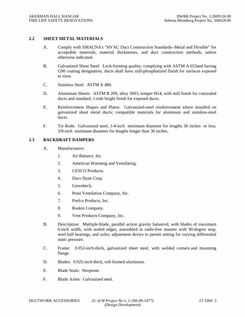
AKERMAN HALL HANGAR BWBR Project No. 3.2009126.00FIRE LIFE SAFETY RENOVATIONS Sebesta Blomberg Project No. 206618.00
DUCTWORK ACCESSORIES (U of M Project No’s. 1-266-09-1477) 23 3300- 3(Design Development)
2.2 SHEET METAL MATERIALS
A. Comply with SMACNA's "HVAC Duct Construction Standards--Metal and Flexible" foracceptable materials, material thicknesses, and duct construction methods, unlessotherwise indicated.
B. Galvanized Sheet Steel: Lock-forming quality; complying with ASTM A 653and havingG90 coating designation; ducts shall have mill-phosphatized finish for surfaces exposedto view.
C. Stainless Steel: ASTM A 480.
D. Aluminum Sheets: ASTM B 209, alloy 3003, temper H14; with mill finish for concealedducts and standard, 1-side bright finish for exposed ducts.
E. Reinforcement Shapes and Plates: Galvanized-steel reinforcement where installed ongalvanized sheet metal ducts; compatible materials for aluminum and stainless-steelducts.
F. Tie Rods: Galvanized steel, 1/4-inch minimum diameter for lengths 36 inches or less;3/8-inch minimum diameter for lengths longer than 36 inches.
2.3 BACKDRAFT DAMPERS
A. Manufacturers:
1. Air Balance, Inc.
2. American Warming and Ventilating.
3. CESCO Products.
4. Duro Dyne Corp.
5. Greenheck.
6. Penn Ventilation Company, Inc.
7. Prefco Products, Inc.
8. Ruskin Company.
9. Vent Products Company, Inc.
B. Description: Multiple-blade, parallel action gravity balanced, with blades of maximum6-inch width, with sealed edges, assembled in rattle-free manner with 90-degree stop,steel ball bearings, and axles; adjustment device to permit setting for varying differentialstatic pressure.
C. Frame: 0.052-inch-thick, galvanized sheet steel, with welded corners and mountingflange.
D. Blades: 0.025-inch-thick, roll-formed aluminum.
E. Blade Seals: Neoprene.
F. Blade Axles: Galvanized steel.

AKERMAN HALL HANGAR BWBR Project No. 3.2009126.00FIRE LIFE SAFETY RENOVATIONS Sebesta Blomberg Project No. 206618.00
DUCTWORK ACCESSORIES (U of M Project No’s. 1-266-09-1477) 23 3300- 4(Design Development)
G. Tie Bars and Brackets: Galvanized steel.
H. Return Spring: Adjustable tension.
2.4 VOLUME DAMPERS
A. Manufacturers:
1. Air Balance, Inc.
2. American Warming and Ventilating.
3. Flexmaster U.S.A., Inc.
4. McGill AirFlow Corporation.
5. METALAIRE, Inc.
6. Nailor Industries Inc.
7. Penn Ventilation Company, Inc.
8. Ruskin Company.
9. Vent Products Company, Inc.
10. Sheet Metal Connectors, Inc.
B. General Description: Factory fabricated, with required hardware and accessories. Stiffendamper blades for stability. Include locking device to hold single-blade dampers in afixed position without vibration. Close duct penetrations for damper components to sealduct consistent with pressure class.
1. Pressure Classes of 3-Inch wg or Higher: End bearings or other seals for ductswith axles full length of damper blades and bearings at both ends of operatingshaft.
C. Standard Volume Dampers: Multiple- or single-blade, parallel- or opposed-blade designas indicated, standard leakage rating, with linkage outside airstream, and suitable forhorizontal or vertical applications.
1. Steel Frames: Hat-shaped, galvanized sheet steel channels, minimum of 0.064inch thick, with mitered and welded corners; frames with flanges whereindicated for attaching to walls and flangeless frames where indicated forinstalling in ducts.
2. Roll-Formed Steel Blades: 0.064-inch- thick, galvanized sheet steel.
3. Blade Axles: Galvanized steel.
4. Bearings: Molded synthetic.
5. Tie Bars and Brackets: Galvanized steel.
D. Low-Leakage Volume Dampers: Multiple- or single-blade, parallel- or opposed-bladedesign as indicated, low-leakage rating, with linkage outside airstream, and suitable forhorizontal or vertical applications.

AKERMAN HALL HANGAR BWBR Project No. 3.2009126.00FIRE LIFE SAFETY RENOVATIONS Sebesta Blomberg Project No. 206618.00
DUCTWORK ACCESSORIES (U of M Project No’s. 1-266-09-1477) 23 3300- 5(Design Development)
1. Steel Frames: U-shaped, galvanized sheet steel channels, minimum of 0.064 inchthick, with mitered and welded corners; frames with flanges where indicated forattaching to walls and flangeless frames where indicated for installing in ducts.
2. Roll-Formed Steel Blades: 0.064-inch- thick, galvanized sheet steel.
3. Blade Axles: Galvanized steel.
4. Bearings: Molded synthetic thrust or ball.
5. Blade Seals: Neoprene.
6. Jamb Seals: Cambered aluminum.
7. Tie Bars and Brackets: Galvanized steel.
E. Jackshaft: 1-inch- diameter, galvanized-steel pipe rotating within pipe-bearing assemblymounted on supports at each mullion and at each end of multiple-damper assemblies.
1. Length and Number of Mountings: Appropriate to connect linkage of eachdamper in multiple-damper assembly.
F. Damper Hardware: Zinc-plated, die-cast core with dial and handle made of 3/32-inch-thick zinc-plated steel, and a 3/4-inch hexagon locking nut. Include center hole to suitdamper operating-rod size. Include elevated platform for insulated duct mounting.
2.5 FIRE DAMPERS
A. Manufacturers:
1. Air Balance, Inc.
2. CESCO Products.
3. Greenheck.
4. McGill AirFlow Corporation.
5. METALAIRE, Inc.
6. Nailor Industries Inc.
7. Penn Ventilation Company, Inc.
8. Prefco Products, Inc.
9. Ruskin Company.
10. Vent Products Company, Inc.
11. Ward Industries, Inc.
B. Fire dampers shall be labeled according to UL 555.
C. Fire Rating: 1-1/2 hours unless otherwise noted.
D. Frame: Curtain type with blades outside airstream; fabricated with roll-formed, 0.034-inch- thick galvanized steel; with mitered and interlocking corners.
E. Mounting Sleeve: Factory- or field-installed, galvanized sheet steel.
1. Minimum Thickness: 0.052 inch thick and of length to suit application.

AKERMAN HALL HANGAR BWBR Project No. 3.2009126.00FIRE LIFE SAFETY RENOVATIONS Sebesta Blomberg Project No. 206618.00
DUCTWORK ACCESSORIES (U of M Project No’s. 1-266-09-1477) 23 3300- 6(Design Development)
2. Exceptions: Omit sleeve where damper frame width permits direct attachment ofperimeter mounting angles on each side of wall or floor, and thickness of damperframe complies with sleeve requirements.
F. Mounting Orientation: Vertical or horizontal as indicated.
G. Blades: Roll-formed, interlocking, 0.034-inch- thick, galvanized sheet steel. In place ofinterlocking blades, use full-length, 0.034-inch- thick, galvanized-steel blade connectors.
H. Horizontal Dampers: Include blade lock and stainless-steel closure spring.
I. Fusible Links: Replaceable, 165 deg F rated.
2.6 CEILING FIRE DAMPERS
A. Manufacturers:
1. Air Balance, Inc.
2. CESCO Products.
3. Greenheck.
4. McGill AirFlow Corporation.
5. METALAIRE, Inc.
6. Nailor Industries Inc.
7. Penn Ventilation Company, Inc.
8. Prefco Products, Inc.
9. Ruskin Company.
10. Vent Products Company, Inc.
11. Ward Industries, Inc.
B. General Description: Labeled according to UL 555C; comply with construction detailsfor tested floor- and roof-ceiling assemblies as indicated in UL's "Fire ResistanceDirectory."
C. Frame: Galvanized sheet steel, round or rectangular, style to suit ceiling construction.
D. Blades: Galvanized sheet steel with refractory insulation.
E. Fusible Links: Replaceable, 165 deg F rated.
2.7 SMOKE DAMPERS
A. Manufacturers:
1. Air Balance, Inc.
2. CESCO Products.
3. Greenheck.
4. Nailor Industries Inc.

AKERMAN HALL HANGAR BWBR Project No. 3.2009126.00FIRE LIFE SAFETY RENOVATIONS Sebesta Blomberg Project No. 206618.00
DUCTWORK ACCESSORIES (U of M Project No’s. 1-266-09-1477) 23 3300- 7(Design Development)
5. Penn Ventilation Company, Inc.
6. Ruskin Company.
B. General Description: Labeled according to UL 555S. Combination fire and smokedampers shall be labeled according to UL 555 for 1-1/2-hour rating.
C. Frame and Blades: 0.064-inch- thick, galvanized sheet steel.
D. Mounting Sleeve: Factory-installed, 0.052-inch-thick, galvanized sheet steel; length tosuit wall or floor application.
E. Damper Motors: Provide for two-position action.
1. Permanent-Split-Capacitor or Shaded-Pole Motors: With oil-immersed andsealed gear trains.
2. Spring-Return Motors: Equip with an integral spiral-spring mechanism whereindicated. Enclose entire spring mechanism in a removable housing designed forservice or adjustments. Size for running torque rating of 150 in. x lbf andbreakaway torque rating of 150 in. x lbf.
3. Outdoor Motors and Motors in Outside-Air Intakes: Equip with O-ring gasketsdesigned to make motors weatherproof. Equip motors with internal heaters topermit normal operation at minus 40 deg F.
4. Electrical Connection: 115 V, single phase, 60 Hz.
2.8 COMBINATION FIRE AND SMOKE DAMPERS
A. Manufacturers:
1. Air Balance, Inc.
2. CESCO Products.
3. Greenheck.
4. Nailor Industries Inc.
5. Penn Ventilation Company, Inc.
6. Ruskin Company.
B. General Description: Labeled according to UL 555S. Combination fire and smokedampers shall be labeled according to UL 555 for 1-1/2-hour rating.
C. Fusible Links: Replaceable, 165 deg F rated.
D. Frame and Blades: 0.064-inch- thick, galvanized sheet steel.
E. Mounting Sleeve: Factory-installed, 0.052-inch- thick, galvanized sheet steel; length tosuit wall or floor application.
F. Damper Motors: Provide for two-position action.
1. Permanent-Split-Capacitor or Shaded-Pole Motors: With oil-immersed andsealed gear trains.

AKERMAN HALL HANGAR BWBR Project No. 3.2009126.00FIRE LIFE SAFETY RENOVATIONS Sebesta Blomberg Project No. 206618.00
DUCTWORK ACCESSORIES (U of M Project No’s. 1-266-09-1477) 23 3300- 8(Design Development)
2. Spring-Return Motors: Equip with an integral spiral-spring mechanism whereindicated. Enclose entire spring mechanism in a removable housing designed forservice or adjustments. Size for running torque rating of 150 in. x lbf andbreakaway torque rating of 150 in. x lbf.
3. Outdoor Motors and Motors in Outside-Air Intakes: Equip with O-ring gasketsdesigned to make motors weatherproof. Equip motors with internal heaters topermit normal operation at minus 40 deg F.
4. Electrical Connection: 115 V, single phase, 60 Hz.
2.9 DUCT SILENCERS
A. Manufacturers:
1. Industrial Noise Control, Inc.
2. McGill AirFlow Corporation.
3. Ruskin Company.
4. Vibro-Acoustics.
B. General Description: Factory-fabricated and -tested, round or rectangular silencers withperformance characteristics and physical requirements as indicated.
C. Fire Performance: Adhesives, sealants, packing materials, and accessory materials shallhave fire ratings not exceeding 25 for flame-spread index and 50 for smoke-developedindex when tested according to ASTM E 84.
D. Rectangular Units: Fabricate casings with a minimum of 0.034-inch-thick, solidgalvanized sheet metal for outer casing and 0.022-inch- thick, ASTM A 653, G90,perforated galvanized sheet metal for inner casing.
E. Round Units:
1. Outer Casings:
a. ASTM A 653, G90, galvanized sheet steel.
b. Up to 24 Inches in Diameter: 0.034 inch thick.
c. 26 through 40 Inches in Diameter: 0.040 inch thick.
d. 42 through 52 Inches in Diameter: 0.052 inch thick.
e. 54 through 60 Inches in Diameter: 0.064 inch thick.
f. Casings fabricated of spiral lock-seam duct may be one size thinner thanthat indicated.
2. Interior Casing, Partitions, and Baffles:
a. ASTM A 653/A 653M, G90, galvanized sheet steel.
b. At least 0.034 inch thick and designed for minimum aerodynamic losses.
F. Sheet Metal Perforations: 1/8-inch diameter for inner casing and baffle sheet metal.

AKERMAN HALL HANGAR BWBR Project No. 3.2009126.00FIRE LIFE SAFETY RENOVATIONS Sebesta Blomberg Project No. 206618.00
DUCTWORK ACCESSORIES (U of M Project No’s. 1-266-09-1477) 23 3300- 9(Design Development)
G. Fill Material: Inert and vermin-proof fibrous material, packed under not less than 5percent compression.
1. Erosion Barrier: Polymer bag enclosing fill and heat-sealed before assembly.
H. Fabricate silencers to form rigid units that will not pulsate, vibrate, rattle, or otherwisereact to system pressure variations.
1. Do not use nuts, bolts, or sheet metal screws for unit assemblies.
2. Lock form and seal or continuously weld joints.
3. Suspended Units: Factory-installed suspension hooks or lugs attached to framein quantities and spaced to prevent deflection or distortion.
4. Reinforcement: Cross or trapeze angles for rigid suspension.
I. Source Quality Control:
1. Acoustic Performance: Test according to ASTM E 477.
2. Record acoustic ratings, including dynamic insertion loss and self-noise powerlevels with an airflow of at least 2000-fpm face velocity.
3. Leak Test: Test units for airtightness at 200 percent of associated fan staticpressure or 6-inch wg static pressure, whichever is greater.
2.10 TURNING VANES
A. Fabricate to comply with SMACNA's "HVAC Duct Construction Standards--Metal andFlexible" for vanes and vane runners. Vane runners shall automatically align vanes.
B. Manufactured Turning Vanes: Fabricate 1-1/2-inch- wide, double-vane, curved blades ofgalvanized sheet steel set 3/4 inch o.c.; support with bars perpendicular to blades set 2inches o.c.; and set into vane runners suitable for duct mounting.
1. Manufacturers:
a. Ductmate Industries, Inc.
b. Duro Dyne Corp.
c. METALAIRE, Inc.
d. Ward Industries, Inc.
e. Sheet Metal Connectors, Inc.
C. Acoustic Turning Vanes: Fabricate airfoil-shaped aluminum extrusions with perforatedfaces and fibrous-glass fill.
2.11 DUCT-MOUNTED ACCESS DOORS
A. General Description: Fabricate doors airtight and suitable for duct pressure class.
B. Door: Double wall, duct mounting, and rectangular; fabricated of galvanized sheet metalwith insulation fill and thickness as indicated for duct pressure class. Include visionpanel at all fire and fire/smoke dampers and where indicated. Include 1-by-1-inch butt orpiano hinge and cam latches.

AKERMAN HALL HANGAR BWBR Project No. 3.2009126.00FIRE LIFE SAFETY RENOVATIONS Sebesta Blomberg Project No. 206618.00
DUCTWORK ACCESSORIES (U of M Project No’s. 1-266-09-1477) 23 3300- 10(Design Development)
1. Manufacturers:
a. American Warming and Ventilating.
b. CESCO Products.
c. Ductmate Industries, Inc.
d. Flexmaster U.S.A., Inc.
e. Greenheck.
f. McGill AirFlow Corporation.
g. Nailor Industries Inc.
h. Ventfabrics, Inc.
i. Ward Industries, Inc.
2. Frame: Galvanized sheet steel, with bend-over tabs and foam gaskets.
3. Provide number of hinges and locks as follows:
a. Less Than 12 Inches Square: Secure with two sash locks.
b. Up to 18 Inches Square: Two hinges and two sash locks.
c. Up to 24 by 48 Inches: Three hinges and two compression latches withoutside and inside handles.
d. Sizes 24 by 48 Inches and Larger: One additional hinge.
C. Door: Double wall, duct mounting, and round; fabricated of galvanized sheet metal withinsulation fill and 1-inch thickness. Include cam latches.
1. Manufacturers:
a. Flexmaster U.S.A., Inc.
2. Frame: Galvanized sheet steel, with spin-in notched frame.
D. Pressure Relief Access Door: Double wall and duct mounting; fabricated of galvanizedsheet metal with insulation fill and thickness as indicated for duct pressure class. Includevision panel where indicated, latches, and retaining chain.
1. Manufacturers:
a. American Warming and Ventilating.
b. CESCO Products.
c. Ductmate Industries, Inc.
d. Greenheck.
e. KEES, Inc.
f. McGill AirFlow Corporation.
g. Nexus PDQ.
2. Frame: Galvanized sheet steel, with bend-over tabs and foam gaskets.
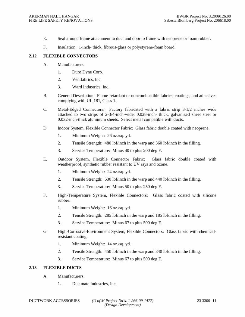
AKERMAN HALL HANGAR BWBR Project No. 3.2009126.00FIRE LIFE SAFETY RENOVATIONS Sebesta Blomberg Project No. 206618.00
DUCTWORK ACCESSORIES (U of M Project No’s. 1-266-09-1477) 23 3300- 11(Design Development)
E. Seal around frame attachment to duct and door to frame with neoprene or foam rubber.
F. Insulation: 1-inch- thick, fibrous-glass or polystyrene-foam board.
2.12 FLEXIBLE CONNECTORS
A. Manufacturers:
1. Duro Dyne Corp.
2. Ventfabrics, Inc.
3. Ward Industries, Inc.
B. General Description: Flame-retardant or noncombustible fabrics, coatings, and adhesivescomplying with UL 181, Class 1.
C. Metal-Edged Connectors: Factory fabricated with a fabric strip 3-1/2 inches wideattached to two strips of 2-3/4-inch-wide, 0.028-inch- thick, galvanized sheet steel or0.032-inch-thick aluminum sheets. Select metal compatible with ducts.
D. Indoor System, Flexible Connector Fabric: Glass fabric double coated with neoprene.
1. Minimum Weight: 26 oz./sq. yd.
2. Tensile Strength: 480 lbf/inch in the warp and 360 lbf/inch in the filling.
3. Service Temperature: Minus 40 to plus 200 deg F.
E. Outdoor System, Flexible Connector Fabric: Glass fabric double coated withweatherproof, synthetic rubber resistant to UV rays and ozone.
1. Minimum Weight: 24 oz./sq. yd.
2. Tensile Strength: 530 lbf/inch in the warp and 440 lbf/inch in the filling.
3. Service Temperature: Minus 50 to plus 250 deg F.
F. High-Temperature System, Flexible Connectors: Glass fabric coated with siliconerubber.
1. Minimum Weight: 16 oz./sq. yd.
2. Tensile Strength: 285 lbf/inch in the warp and 185 lbf/inch in the filling.
3. Service Temperature: Minus 67 to plus 500 deg F.
G. High-Corrosive-Environment System, Flexible Connectors: Glass fabric with chemical-resistant coating.
1. Minimum Weight: 14 oz./sq. yd.
2. Tensile Strength: 450 lbf/inch in the warp and 340 lbf/inch in the filling.
3. Service Temperature: Minus 67 to plus 500 deg F.
2.13 FLEXIBLE DUCTS
A. Manufacturers:
1. Ductmate Industries, Inc.

AKERMAN HALL HANGAR BWBR Project No. 3.2009126.00FIRE LIFE SAFETY RENOVATIONS Sebesta Blomberg Project No. 206618.00
DUCTWORK ACCESSORIES (U of M Project No’s. 1-266-09-1477) 23 3300- 12(Design Development)
2. Flexmaster U.S.A., Inc.
3. Hart & Cooley, Inc.
4. McGill AirFlow Corporation.
B. Noninsulated-Duct Connectors: UL 181, Class 1, 2-ply vinyl film supported by helicallywound, spring-steel wire.
1. Pressure Rating: 10-inch wg positive and 1.0-inch wg negative.
2. Maximum Air Velocity: 4000 fpm.
3. Temperature Range: Minus 10 to plus 160 deg F.
C. Insulated-Duct Connectors: UL 181, Class 1, 2-ply vinyl film supported by helicallywound, spring-steel wire; fibrous-glass insulation; aluminized vapor barrier film.
1. Pressure Rating: 10-inch wg positive and 1.0-inch wg negative.
2. Maximum Air Velocity: 4000 fpm.
3. Temperature Range: Minus 10 to plus 160 deg F.
D. Flexible Duct Clamps: Stainless-steel band with cadmium-plated hex screw to tightenband with a worm-gear action, in sizes 3 through 18 inches to suit duct size.
2.14 DUCT ACCESSORY HARDWARE
A. Instrument Test Holes: Cast iron or cast aluminum to suit duct material, including screwcap and gasket. Size to allow insertion of pitot tube and other testing instruments and oflength to suit duct insulation thickness.
B. Adhesives: High strength, quick setting, neoprene based, waterproof, and resistant togasoline and grease.
PART 3 - EXECUTION
3.1 APPLICATION AND INSTALLATION
A. Install duct accessories according to applicable details in SMACNA's "HVAC DuctConstruction Standards--Metal and Flexible" for metal ducts.
B. Provide duct accessories of materials suited to duct materials; use galvanized-steelaccessories in galvanized-steel ducts, stainless-steel accessories in stainless-steel ducts,and aluminum accessories in aluminum ducts.
C. Install backdraft dampers on exhaust fans or exhaust ducts nearest to outside and whereindicated.
D. Provide balancing dampers at points on supply, return, and exhaust systems wherebranches lead from larger ducts as required for air balancing. Install at a minimum oftwo duct widths from branch takeoff.
E. Provide test holes at fan inlets and outlets and elsewhere as indicated.
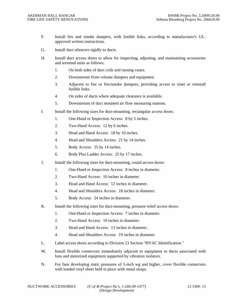
AKERMAN HALL HANGAR BWBR Project No. 3.2009126.00FIRE LIFE SAFETY RENOVATIONS Sebesta Blomberg Project No. 206618.00
DUCTWORK ACCESSORIES (U of M Project No’s. 1-266-09-1477) 23 3300- 13(Design Development)
F. Install fire and smoke dampers, with fusible links, according to manufacturer's UL-approved written instructions.
G. Install duct silencers rigidly to ducts.
H. Install duct access doors to allow for inspecting, adjusting, and maintaining accessoriesand terminal units as follows:
1. On both sides of duct coils and turning vanes.
2. Downstream from volume dampers and equipment.
3. Adjacent to fire or fire/smoke dampers, providing access to reset or reinstallfusible links.
4. On sides of ducts where adequate clearance is available.
5. Downstream of duct mounted air flow measuring stations.
I. Install the following sizes for duct-mounting, rectangular access doors:
1. One-Hand or Inspection Access: 8 by 5 inches.
2. Two-Hand Access: 12 by 6 inches.
3. Head and Hand Access: 18 by 10 inches.
4. Head and Shoulders Access: 21 by 14 inches.
5. Body Access: 25 by 14 inches.
6. Body Plus Ladder Access: 25 by 17 inches.
J. Install the following sizes for duct-mounting, round access doors:
1. One-Hand or Inspection Access: 8 inches in diameter.
2. Two-Hand Access: 10 inches in diameter.
3. Head and Hand Access: 12 inches in diameter.
4. Head and Shoulders Access: 18 inches in diameter.
5. Body Access: 24 inches in diameter.
K. Install the following sizes for duct-mounting, pressure relief access doors:
1. One-Hand or Inspection Access: 7 inches in diameter.
2. Two-Hand Access: 10 inches in diameter.
3. Head and Hand Access: 13 inches in diameter.
4. Head and Shoulders Access: 19 inches in diameter.
L. Label access doors according to Division 23 Section "HVAC Identification."
M. Install flexible connectors immediately adjacent to equipment in ducts associated withfans and motorized equipment supported by vibration isolators.
N. For fans developing static pressures of 5-inch wg and higher, cover flexible connectorswith loaded vinyl sheet held in place with metal straps.

AKERMAN HALL HANGAR BWBR Project No. 3.2009126.00FIRE LIFE SAFETY RENOVATIONS Sebesta Blomberg Project No. 206618.00
DUCTWORK ACCESSORIES (U of M Project No’s. 1-266-09-1477) 23 3300- 14(Design Development)
O. Connect terminal units to supply ducts directly. Do not use flexible ducts.
P. Connect diffusers or light troffer boots to low pressure ducts directly or with maximum60-inch lengths of flexible duct clamped or strapped in place.
Q. Connect flexible ducts to metal ducts with draw bands.
R. Install duct test holes where indicated and required for testing and balancing purposes.
3.2 ADJUSTING
A. Adjust duct accessories for proper settings.
B. Adjust fire and smoke dampers for proper action.
C. Positioning all manual-volume dampers fully open before start of testing adjusting andbalancing.
END OF SECTION 23 3300

AKERMAN HALL HANGAR BWBR Project No. 3.2009126.00FIRE LIFE SAFETY RENOVATIONS Sebesta Blomberg Project No. 206618.00
CENTRIFUGAL FANS (U of M Project No’s. 1-266-09-1477) 23 3416 - 1(Design Development)
SECTION 23 3416
CENTRIFUGAL FANS
PART 1 - GENERAL
1.1 RELATED DOCUMENTS
A. Drawings and general provisions of the Contract, including General and SupplementaryConditions and Division 1 Specification Sections, apply to this Section.
1.2 SUMMARY
A. This Section includes centrifugal fans.
1.3 PERFORMANCE REQUIREMENTS
A. Operating Limits: Classify according to AMCA 99.
1.4 SUBMITTALS
A. Product Data: Include rated capacities, furnished specialties, and accessories for eachtype of product indicated and include the following:
1. Certified fan performance curves with system operating conditions indicated.
2. Certified fan sound-power ratings.
3. Motor ratings and electrical characteristics, plus motor and electrical accessories.
4. Material gages and finishes, including color charts.
5. Dampers, including housings, linkages, and operators.
B. Shop Drawings: Detail equipment assemblies and indicate dimensions, weights, loads,required clearances, method of field assembly, components, and location and size of eachfield connection.
1. Wiring Diagrams: Power, signal, and control wiring. Differentiate betweenmanufacturer-installed and field-installed wiring.
2. Vibration Isolation Base Details: Detail fabrication, including anchorages andattachments to structure and to supported equipment. Include auxiliary motorslides and rails, and base weights.
C. Maintenance Data: For centrifugal fans to include in maintenance manuals specified inDivision 1.
1.5 QUALITY ASSURANCE
A. Electrical Components, Devices, and Accessories: Listed and labeled as defined inNFPA 70, Article 100, by a testing agency acceptable to authorities having jurisdiction,and marked for intended use.
AKERMAN HALL HANGAR BWBR Project No. 3.2009126.00FIRE LIFE SAFETY RENOVATIONS Sebesta Blomberg Project No. 206618.00
CENTRIFUGAL FANS (U of M Project No’s. 1-266-09-1477) 23 3416 - 2(Design Development)
B. AMCA Compliance: Products shall comply with performance requirements and shall belicensed to use the AMCA-Certified Ratings Seal.
C. NEMA Compliance: Motors and electrical accessories shall comply with NEMAstandards.
1.6 DELIVERY, STORAGE, AND HANDLING
A. Deliver fans as factory-assembled units, to the extent allowable by shipping limitations,with protective crating and covering.
B. Disassemble and reassemble units, as required for moving to the final location, accordingto manufacturer's written instructions.
C. Lift and support units with manufacturer's designated lifting or supporting points.
1.7 COORDINATION
A. Coordinate size and location of structural-steel support members.
B. Coordinate size and location of concrete bases. Cast anchor-bolt inserts into bases.Concrete, reinforcement, and formwork requirements are specified in Division 3 Section"Cast-in-Place Concrete."
1.8 EXTRA MATERIALS
A. Furnish extra materials described below that match products installed and that arepackaged with protective covering for storage and identified with labels describingcontents.
1. Belts: One set for each belt-driven unit.
PART 2 - PRODUCTS
2.1 MANUFACTURERS
A. Manufacturers: Subject to compliance with requirements, provide products by one of thefollowing:
1. Aerovent; a Twin City Fan Company.
2. Ammerman Company, Inc./General Resource Corp.
3. Buffalo Forge Co./Howden Fan Co.
4. Central Blower Co.
5. Chicago Blower Corp.
6. Cook, Loren Company.
7. Industrial Air Division, Lau Commercial Industrial Fans/Lau Industries.
8. Trane Co. (The).

AKERMAN HALL HANGAR BWBR Project No. 3.2009126.00FIRE LIFE SAFETY RENOVATIONS Sebesta Blomberg Project No. 206618.00
CENTRIFUGAL FANS (U of M Project No’s. 1-266-09-1477) 23 3416 - 3(Design Development)
2.2 MANUFACTURED UNITS
A. Description: Factory-fabricated, -assembled, -tested, and -finished, belt-drivencentrifugal fans consisting of housing, wheel, fan shaft, bearings, motor and disconnectswitch, drive assembly, and support structure.
2.3 HOUSINGS
A. Materials and Fabrication: Formed and reinforced steel panels to make curved scrollhousings with shaped cutoff, spun-metal inlet bell, and doors or panels to allow access tointernal parts and components.
1. Panel Bracing: Steel angle- or channel-iron member supports for mounting andsupporting fan scroll, wheel, motor, and accessories.
2. Fabrication Class: AMCA 99, Class I, Class II, or Class III.
3. Horizontal Flanged Split Housing: Bolted construction.
B. Coatings: Powder-baked enamel.
2.4 WHEELS
A. Backward-Inclined Fan Wheels: Steel construction with curved inlet flange, back plate,backward-inclined blades continuously welded to the back plate; cast-iron or cast-steelhub riveted to back plate and fastened to shaft with set screws.
B. Forward-Curved Fan Wheels: Black-enameled or galvanized steel construction with inletflange, back plate, shallow blades with inlet and tip curved forward in direction ofairflow, mechanically secured to flange and back plate; cast-steel hub swaged to backplate and fastened to shaft with set screws.
C. Airfoil-Fan Wheels: Steel construction with smooth-curved inlet flange; heavy backplate; hollow die-formed, airfoil-shaped blades continuously welded at tip flange andback plate; cast-iron or cast-steel hub riveted to back plate and fastened to shaft with setscrews.
D. Coatings: Powder-baked enamel.
2.5 SHAFTS
A. Statically and dynamically balanced and selected for continuous operation at maximumrated fan speed and motor horsepower, with final alignment and belt adjustment madeafter installation.
B. Turned, ground, and polished hot-rolled steel with keyway. Ship with a protectivecoating of lubricating oil.
C. Designed to operate at no more than 70 percent of first critical speed at top of fan's speedrange.
2.6 BEARINGS
A. Grease-Lubricated Shaft Bearings: Self-aligning, pillow-block-type, ball or rollerbearings with adapter mount and two-piece, cast-iron housing.

AKERMAN HALL HANGAR BWBR Project No. 3.2009126.00FIRE LIFE SAFETY RENOVATIONS Sebesta Blomberg Project No. 206618.00
CENTRIFUGAL FANS (U of M Project No’s. 1-266-09-1477) 23 3416 - 4(Design Development)
1. Ball-Bearing Rating Life: ABMA 9, L10 of 120,000 hours.
2. Roller-Bearing Rating Life: ABMA 11, L10 of 120,000 hours.
2.7 BELT DRIVES
A. Description: Factory mounted, with final alignment and belt adjustment made afterinstallation.
1. Service Factor Based on Fan Motor: 1.2.
B. Fan Pulleys: Cast iron or cast steel with split, tapered bushing; dynamically balanced atfactory.
C. Motor Pulleys: Adjustable pitch for use with motors through 5 hp; fixed pitch for usewith motors larger than 5 hp. Select pulley so pitch adjustment is at the middle ofadjustment range at fan design conditions.
D. Belts: Oil resistant, nonsparking, and nonstatic; matched sets for multiple belt drives.
1. Belt Guards: Fabricate to comply with OSHA and SMACNA requirements;0.1046-inch-thick, 3/4-inchdiamond-mesh wire screen welded to steel angleframe or equivalent, prime coated. Secure to fan or fan supports without shortcircuiting vibration isolation. Include provisions for adjustment of belt tension,lubrication, and use of tachometer with guard in place.
E. Motor Mount: Adjustable for belt tensioning.
2.8 ACCESSORIES
A. Scroll Access Doors: Shaped to conform to scroll, with quick-opening latches andgaskets.
B. Companion Flanges: Galvanized steel, for duct connections.
2.9 MOTORS
A. Refer to Division 15 Section "Motors" for general requirements for factory-installedmotors.
B. Motor Construction: NEMA MG 1, general purpose, continuous duty, high efficiency,Design B.
C. Enclosure Type: Provide where indicated
1. Open drip proof where satisfactorily housed or remotely located duringoperation.
2. Guarded drip proof where exposed to contact by employees or buildingoccupants.
2.10 SOURCE QUALITY CONTROL
A. Sound-Power Level Ratings: Comply with AMCA 301, "Methods for Calculating FanSound Ratings from Laboratory Test Data." Factory test fans according to AMCA 300,

AKERMAN HALL HANGAR BWBR Project No. 3.2009126.00FIRE LIFE SAFETY RENOVATIONS Sebesta Blomberg Project No. 206618.00
CENTRIFUGAL FANS (U of M Project No’s. 1-266-09-1477) 23 3416 - 5(Design Development)
"Reverberant Room Method for Sound Testing of Fans." Label fans with the AMCA-Certified Ratings Seal.
B. Fan Performance Ratings: Establish flow rate, pressure, power, air density, speed ofrotation, and efficiency by factory tests and ratings according to AMCA 210, "LaboratoryMethods of Testing Fans for Rating."
PART 3 - EXECUTION
3.1 INSTALLATION
A. Install centrifugal fans level and plumb.
B. Support floor-mounting units using restrained spring isolators having a static deflectionof 1 inch.
1. Secure vibration isolators to concrete bases using anchor bolts cast in concretebase.
C. Install floor-mounting units on concrete bases. Concrete, reinforcement, and formworkrequirements are specified in Division 3 Section "Cast-in-Place Concrete."
D. Install units with clearances for service and maintenance.
E. Label fans according to requirements specified in Division 15 Section "MechanicalIdentification."
3.2 CONNECTIONS
A. Duct installation and connection requirements are specified in other Division 15 Sections.Drawings indicate general arrangement of ducts and duct accessories. Make final ductconnections with flexible connectors. Flexible connectors are specified in Division 15Section "Duct Accessories."
B. Install ducts adjacent to fans to allow service and maintenance.
C. Ground equipment.
D. Tighten electrical connectors and terminals according to manufacturer's published torque-tightening values. If manufacturer's torque values are not indicated, use those specifiedin UL 486A and UL 486B.
3.3 FIELD QUALITY CONTROL
A. Equipment Startup Checks:
1. Verify that shipping, blocking, and bracing are removed.
2. Verify that unit is secure on mountings and supporting devices and thatconnections to ducts and electrical components are complete. Verify that properthermal-overload protection is installed in motors, starters, and disconnectswitches.
3. Verify that cleaning and adjusting are complete.

AKERMAN HALL HANGAR BWBR Project No. 3.2009126.00FIRE LIFE SAFETY RENOVATIONS Sebesta Blomberg Project No. 206618.00
CENTRIFUGAL FANS (U of M Project No’s. 1-266-09-1477) 23 3416 - 6(Design Development)
4. Disconnect fan drive from motor, verify proper motor rotation direction, andverify fan wheel free rotation and smooth bearing operation. Reconnect fan drivesystem, align and adjust belts, and install belt guards.
5. Verify lubrication for bearings and other moving parts.
6. Verify that manual and automatic volume control and fire and smoke dampers inconnected ductwork systems are in fully open position.
B. Starting Procedures:
1. Energize motor and adjust fan to indicated rpm.
2. Measure and record motor voltage and amperage.
C. Operational Test: After electrical circuitry has been energized, start units to confirmproper motor rotation and unit operation. Remove malfunctioning units, replace withnew units, and retest.
D. Test and adjust controls and safeties. Replace damaged and malfunctioning controls andequipment.
E. Shut unit down and reconnect automatic temperature-control operators.
F. Refer to Division 15 Section "Testing, Adjusting, and Balancing" for testing, adjusting,and balancing procedures.
G. Replace fan and motor pulleys as required to achieve design airflow.
H. Repair or replace malfunctioning units. Retest as specified above after repairs orreplacements are made.
3.4 ADJUSTING
A. Adjust damper linkages for proper damper operation.
B. Adjust belt tension.
C. Lubricate bearings.
3.5 CLEANING
A. On completion of installation, internally clean fans according to manufacturer's writteninstructions. Remove foreign material and construction debris. Vacuum fan wheel andcabinet.
B. After completing system installation, including outlet fitting and devices, inspect exposedfinish. Remove burrs, dirt, and construction debris and repair damaged finishes.
3.6 DEMONSTRATION
A. Engage a factory-authorized service representative to train Owner's maintenancepersonnel to adjust, operate, and maintain centrifugal fans.
1. Train Owner's maintenance personnel on procedures and schedules for startingand stopping, troubleshooting, servicing, and maintaining equipment andschedules.

AKERMAN HALL HANGAR BWBR Project No. 3.2009126.00FIRE LIFE SAFETY RENOVATIONS Sebesta Blomberg Project No. 206618.00
CENTRIFUGAL FANS (U of M Project No’s. 1-266-09-1477) 23 3416 - 7(Design Development)
2. Review data in maintenance manuals. Refer to Division 1 Section "CloseoutProcedures."
3. Review data in maintenance manuals. Refer to Division 1 Section "Operationand Maintenance Data."
4. Schedule training with Owner, through Architect, with at least seven days'advance notice.
END OF SECTION 23 3416

AKERMAN HALL HANGAR BWBR Project No. 3.2009126.00FIRE LIFE SAFETY RENOVATIONS Sebesta Blomberg Project No. 206618.00
AIR TERMINAL UNITS (U of M Project No’s. 1-266-09-1477) 23 36 00 - 1(Design Development)
SECTION 23 36 00
AIR TERMINAL UNITS
PART 1 - GENERAL
1.1 RELATED DOCUMENTS
A. Drawings and general provisions of the Contract, including General and SupplementaryConditions and Division 1 Specification Sections, apply to this Section.
1.2 SUMMARY
A. This Section includes the following:
1. Single-duct air terminal units.
1.3 SUBMITTALS
A. Product Data: For each type of product indicated, include rated capacities, furnishedspecialties, sound-power ratings, and accessories.
B. Shop Drawings: Detail equipment assemblies and indicate dimensions, requiredclearances, method of field assembly, components, and location and size of each fieldconnection.
1. Include a schedule showing unique model designation, room location, modelnumber, size, and accessories furnished.
2. Wiring Diagrams: Power, signal, and control wiring.
C. Operation and Maintenance Data: For air terminal units to include in emergency,operation, and maintenance manuals. In addition to items specified in Division 1 includethe following:
1. Instructions for resetting minimum and maximum air volumes.
2. Instructions for adjusting software set points.
1.4 QUALITY ASSURANCE
A. Product Options: Drawings indicate size, profiles, and dimensional requirements of airterminal units and are based on the specific system indicated. Refer to Division 1 Section"Product Requirements."
B. Electrical Components, Devices, and Accessories: Listed and labeled as defined inNFPA 70, Article 100, by a testing agency acceptable to authorities having jurisdiction,and marked for intended use.
C. NFPA Compliance: Install air terminal units according to NFPA 90A, "Standard for theInstallation of Air Conditioning and Ventilating Systems."

AKERMAN HALL HANGAR BWBR Project No. 3.2009126.00FIRE LIFE SAFETY RENOVATIONS Sebesta Blomberg Project No. 206618.00
AIR TERMINAL UNITS (U of M Project No’s. 1-266-09-1477) 23 36 00 - 2(Design Development)
1.5 COORDINATION
A. Coordinate layout and installation of air terminal units and suspension system with otherconstruction that penetrates ceilings or is supported by them, including light fixtures,HVAC equipment, fire-suppression system, and partition assemblies.
PART 2 - PRODUCTS
2.1 MANUFACTURERS
A. Manufacturers: Subject to compliance with requirements, provide products by one of themanufacturers specified.
1. Anemostat; a Mestek Company.
2. Carnes.
3. Environmental Technologies, Inc.; Enviro-Air Div.
4. Krueger.
5. METALAIRE, Inc.; Metal Industries Inc.
6. Nailor Industries of Texas Inc.
7. Price Industries.
8. Titus.
9. Tuttle & Bailey.
2.2 SINGLE-DUCT AIR TERMINAL UNITS
A. Configuration: Volume-damper assembly inside unit casing with control componentslocated inside a protective metal shroud.
B. Casing: Construct casings of minimum 0.034-inch (22 gauge) steel.
1. Casing Lining: Line inside surfaces of casings with a minimum of 1/2-inch-thick,fibrous-glass insulation; 1.5-lb/cu. ft. density with non-porous 0.001” scrimbacked aluminum foil liner, complying with NFPA 90A requirements andUL 181 erosion requirements. Secure lining to prevent delamination, sagging, orsettling. Discharge edges of the unit liner shall be secured with Z-shaped metalbrackets along entire perimeter of opening.
2. Casing Leakage: Construct casings such that when subjected to 0.5 in wgpressure the total leakage does not 4% of specified airflow capacity with outletsealed and inlet wide open.
3. Air Inlet: Round stub connection or S-slip and drive connections for ductattachment.
4. Air Outlet: Rectangular S-slip and drive connections.
5. Access: Removable panels for access to dampers and other parts requiringservice, adjustment, or maintenance; with airtight gasket.

AKERMAN HALL HANGAR BWBR Project No. 3.2009126.00FIRE LIFE SAFETY RENOVATIONS Sebesta Blomberg Project No. 206618.00
AIR TERMINAL UNITS (U of M Project No’s. 1-266-09-1477) 23 36 00 - 3(Design Development)
C. Volume Damper: Galvanized steel with synthetic peripheral gasket and self-lubricatingbearings. Damper shaft shall be constructed of low thermal conductive material. Shaftshall be permanently and clearly stamped on the end to indicate damper position and shallbe suitable for direct mounting of damper actuator. Damper shall incorporate amechanical stop to prevent overstroking.
1. Maximum Damper Leakage: ARI 880 rated. Construct air dampers such thatwhen subjected to 3.0 in wg inlet pressure the total leakage with damper fullyclosed does not exceed 1.0% of the maximum rated airflow capacity.
2. Damper Position: Normally closed.
D. Velocity Sensor: Provide multi-point, center averaging velocity sensor with a minimumof four measuring ports parallel to the take-off point from the sensor. Sensor shallprovide a minimum differential pressure signal of 0.03” wg. at an inlet velocity of 500fpm or less.
1. Sensor Tubing: Pneumatic sensor tubing shall be UL listed fire retardant (FR)virgin polyethylene provided by terminal unit manufacturer. Provide brass flowmeasurement taps in sensor tubing for field verification of cfm by hand-held flowtransducer.
2. Calibration Charts: Manufacturer shall provide flow versus pressure differentialchart for each terminal unit to allow for field verification of calibration.
E. Hot-Water Heating Coil (Where scheduled): Factory installed with copper tube,mechanically expanded into heavy gauge aluminum-plate fins; leak tested underwater to200 psig. Tubes shall have a minimum wall thickness of 0.016”. Number of coil rows,circuits, and fin spacing shall be selected to meet performance requirements as indicatedon the drawings and schedules.
F. Control Panel Enclosure: NEMA 1, with access panel sealed from airflow and mountedon side of unit.
G. DDC Controls: Electronic damper actuator, flow transducer, and control module shall beprovided and field mounted by the Temperature Control Contractor. All power andcontrol wiring shall be plenum rated.
2.3 SOURCE QUALITY CONTROL
A. Identification: Label each air terminal unit with plan number, nominal airflow, maximumand minimum factory-set airflows, coil type, and ARI certification seal.
B. Verification of Performance: Rate air terminal units according to ARI 880.
PART 3 - EXECUTION
3.1 INSTALLATION
A. Install air terminal units level and plumb. Maintain sufficient clearance for normalservice and maintenance.

AKERMAN HALL HANGAR BWBR Project No. 3.2009126.00FIRE LIFE SAFETY RENOVATIONS Sebesta Blomberg Project No. 206618.00
AIR TERMINAL UNITS (U of M Project No’s. 1-266-09-1477) 23 36 00 - 4(Design Development)
3.2 CONNECTIONS
A. Piping installation requirements are specified in other Division 23 Sections. Drawingsindicate general arrangement of piping, fittings, and specialties.
B. Install piping adjacent to air terminal units to allow service and maintenance.
C. Hot-Water Piping: In addition to requirements in Division 23 Section "Hydronic Piping,"connect heating coils to supply with shutoff valve, strainer, control valve, and union orflange; and to return with balancing valve and union or flange.
D. Connect ducts to air terminal units according to Division 23 Section "Metal Ductwork"
3.3 FIELD QUALITY CONTROL
A. Perform the following field tests and inspections and prepare test reports:
1. After installing air terminal units and after electrical circuitry has been energized,test for compliance with requirements.
2. Leak Test: After installation, fill water coils and test for leaks. Repair leaks andretest until no leaks exist.
3. Operational Test: After electrical circuitry has been energized, start units toconfirm proper motor rotation and unit operation.
4. Test and adjust controls and safeties. Replace damaged and malfunctioningcontrols and equipment.
B. Remove and replace malfunctioning units and retest as specified above.
3.4 DEMONSTRATION
A. Train Owner's maintenance personnel to adjust, operate, and maintain air terminal units.Refer to Division 1
END OF SECTION

AKERMAN HALL HANGAR BWBR Project No. 3.2009126.00FIRE LIFE SAFETY RENOVATIONS Sebesta Blomberg Project No. 206618.00
DIFFUSERS, REGISTERS (U of M Project No’s. 1-266-09-1477) 23 37 13 - 1AND GRILLS (Design Development)
SECTION 23 37 13
DIFFUSERS, REGISTERS, AND GRILLES
PART 1 - GENERAL
1.1 RELATED DOCUMENTS
A. Drawings and general provisions of the Contract, including General and SupplementaryConditions and Division 1 Specification Sections, apply to this Section.
1.2 SUMMARY
A. This Section includes ceiling- and wall-mounted diffusers, registers, and grilles.
B. Related Sections include the following:
1. Division 8 Section "Louvers and Vents" for fixed and adjustable louvers and wallvents, whether or not they are connected to ducts.
2. Division 23 Section "Duct Accessories" for fire and smoke dampers and volume-control dampers not integral to diffusers, registers, and grilles.
1.3 SUBMITTALS
A. Product Data: For each product indicated, include the following:
1. Data Sheet: Indicate materials of construction, finish, and mounting details; andperformance data including throw and drop, static-pressure drop, and noiseratings.
2. Diffuser, Register, and Grille Schedule: Indicate Drawing designation, roomlocation, quantity, model number, size, and accessories furnished.
B. Coordination Drawings: Reflected ceiling plans, drawn to scale, on which the followingitems are shown and coordinated with each other, based on input from installers of theitems involved:
1. Ceiling suspension assembly members.
2. Method of attaching hangers to building structure.
3. Size and location of initial access modules for acoustical tile.
4. Ceiling-mounted items including lighting fixtures, diffusers, grilles, speakers,sprinklers, access panels, and special moldings.
5. Duct access panels.
PART 2 - PRODUCTS
2.1 DIFFUSERS REGISTERS AND GRILLES
A. Drawings and schedules indicate specific requirements of diffusers, registers, and grillesand are based on the performance of the products listed.
AKERMAN HALL HANGAR BWBR Project No. 3.2009126.00FIRE LIFE SAFETY RENOVATIONS Sebesta Blomberg Project No. 206618.00
DIFFUSERS, REGISTERS (U of M Project No’s. 1-266-09-1477) 23 37 13 - 2AND GRILLS (Design Development)
1. Manufacturers: Subject to compliance with requirements, provide products byone of the manufacturers specified.
a. Anemostat; a Mestek Company.
b. Carnes.
c. Krueger.
d. METALAIRE, Inc.; Metal Industries Inc.
e. Nailor Industries of Texas Inc.
f. Price Industries.
g. Titus.
h. Tuttle & Bailey.
2.2 SOURCE QUALITY CONTROL
A. Verification of Performance: Rate diffusers, registers, and grilles according toASHRAE 70, "Method of Testing for Rating the Performance of Air Outlets and Inlets."
PART 3 - EXECUTION
3.1 EXAMINATION
A. Examine areas where diffusers, registers, and grilles are to be installed for compliancewith requirements for installation tolerances and other conditions affecting performanceof equipment.
B. Proceed with installation only after unsatisfactory conditions have been corrected.
3.2 INSTALLATION
A. Install diffusers, registers, and grilles level and plumb.
B. Ceiling-Mounted Outlets and Inlets: Drawings indicate general arrangement of ducts,fittings, and accessories. Air outlet and inlet locations have been indicated to achievedesign requirements for air volume, noise criteria, airflow pattern, throw, and pressuredrop. Make final locations where indicated, as much as practicable. For units installed inlay-in ceiling panels, locate units in the center of panel. Where architectural features orother items conflict with installation, notify Architect for a determination of finallocation.
C. Install diffusers, registers, and grilles with airtight connections to ducts and to allowservice and maintenance of dampers, air extractors, and fire dampers.
3.3 ADJUSTING
A. After installation, adjust diffusers, registers, and grilles to air patterns indicated, or asdirected, before starting air balancing.
END OF SECTION 23 37 13

AKERMAN HALL HANGAR BWBR Project No. 3.2009126.00FIRE LIFE SAFETY RENOVATIONS Sebesta Blomberg Project No. 206618.00
HVAC GRAVITY VENTILATORS (U of M Project No’s. 1-266-09-1477) 23 37 23 - 1(Design Development)
SECTION 23 37 23
HVAC GRAVITY VENTILATORS
PART 1 - GENERAL
1.1 RELATED DOCUMENTS
A. Drawings and general provisions of the Contract, including General and SupplementaryConditions and Division 1 Specification Sections, apply to this Section.
1.2 SUMMARY
A. This Section includes the following types of roof-mounting intake and relief ventilators:
1. Roof hoods
B. Related Sections include the following:
1. Division 23 Section “Power Ventilators” for roof-mounting exhaust fans.
1.3 PERFORMANCE REQUIREMENTS
A. Structural Performance: Intake and relief ventilators shall be capable of withstanding theeffects of gravity loads, wind loads and thermal movements without permanentdeformation of components, noise or metal fatigue, or permanent damage to fasteners andanchors.
1.4 SUBMITTALS
A. Shop Drawings: For intake and relief ventilators. Include plans, elevations, sections,details and ventilator attachments to curbs and curb attachments to roof structure.
B. Coordination Drawings: Roof framing plans and other details, drawn to scale, on whichthe following items are shown and coordinated with each other, based on input frominstallers of the items involved:
1. Structural members to which roof curbs and ventilators will be attached.
2. Sizes and locations of roof openings.
C. Samples for Verification: For each type of exposed finish required for intake and reliefventilators.
D. Welding certificates.
1.5 QUALITY ASSURANCE
A. Source Limitations: Obtain ventilators through one source from a single manufacturerwhere indicated to be of same type, design, or factory-applied color finish.
AKERMAN HALL HANGAR BWBR Project No. 3.2009126.00FIRE LIFE SAFETY RENOVATIONS Sebesta Blomberg Project No. 206618.00
HVAC GRAVITY VENTILATORS (U of M Project No’s. 1-266-09-1477) 23 37 23 - 2(Design Development)
B. Product Options: Drawings indicate size, profiles, and dimensional requirements ofintake and relief ventilators and are based on the specific equipment indicated. Refer toDivision 1 Section “Product Requirements.”
1. Do not modify intended aesthetic effects, as judged solely by Architect, exceptwith Architect’s approval. If modifications are proposed, submit comprehensiveexplanatory data to Architect for review.
C. Welding: Qualify procedures and personnel according to the following:
1. AWS D1.2, “Structural Welding Code—Aluminum.”
2. AWS D1.3, “Structural Welding Code—Sheet Steel.”
1.6 COORDINATION
A. Coordinate installation of roof curbs and roof penetrations. These items are specified inDivision 7 Section “Roof Accessories.”
PART 2 - PRODUCTS
2.1 MANUFACTURERS
A. In other Part 2 articles where titles below introduce lists, the following requirementsapply to product selection:
1. Manufacturers: Subject to compliance with requirements, provide products byone of the manufacturers specified.
2.2 MATERIALS
A. Aluminum Extrusions: ASTM B 221, Alloy 6063-T5or T52.
B. Aluminum Sheet: ASTM B 209, Alloy 3003 or 5005 with temper as required for formingor as otherwise recommended by metal produce for required finish.
C. Galvanized-Steel Sheet: ASTM A 653, G90 zinc coating, mill phosphatized
D. Fasteners: Same basic metal and alloy as fastened metal or 300 Series stainless steel,unless otherwise indicated. Do not use metals that are incompatible with joined materials
1. Use types and sizes to suit unit installation conditions.
2. Use hex-head or Phillips panhead screws for exposed fasteners, unless otherwiseindicated.
E. Bituminous Paint: Cold-applied asphalt emulsion complying with ASTM D 1187.
2.3 FABRICATION, GENERAL
A. Factory fabricate intake and relief ventilators to minimize field splicing and assembly.Disassemble units to the minimum extent as necessary for shipping and handling.Clearly mark units for reassembly and coordinated installation.
AKERMAN HALL HANGAR BWBR Project No. 3.2009126.00FIRE LIFE SAFETY RENOVATIONS Sebesta Blomberg Project No. 206618.00
HVAC GRAVITY VENTILATORS (U of M Project No’s. 1-266-09-1477) 23 37 23 - 3(Design Development)
B. Fabricate frames, including integral bases, to fit in openings of sizes indicated, withallowances made for fabrication and installation tolerances, adjoining material tolerances,and perimeter sealant joints.
C. Fabricate units with closely fitted joints and exposed connections accurately located andsecured.
D. Fabricate supports, anchorages, and accessories required for complete assembly.
E. Preform shop welding by AWS-certified procedures and personnel.
2.4 ROOF HOODS
A. Available Manufacturers:
1. Acme Engineering & Mfg. Corp.
2. Carnes.
3. Greenheck.
4. Loren Cook Company.
5. Penn Ventilation.
B. Factory fabricate according to SMACNA’s “HVAC Duct Construction Standards – Metaland Flexible,” Figures 5-6 and 5-7.
C. Materials: Galvanized-steel sheet, minimum 0.064-inch thick base and 0.040-inch- thickhood or Aluminum sheet, minimum 0.063-inch thick base and 0.050-inch thick hood;suitably reinforced to match hoods indicated in schedule on plans.
D. Roof Curbs: Galvanized-steel sheet; with mitered and welded corners; 1-1/2-inch- thick,rigid fiberglass insulation adhered to inside walls; and 1-1/2-inch wood nailer. Size asrequired to fit roof opening and ventilator base.
1. Configuration: Built-in cant mounting flange.
2. Overall Height: 8 inches 18 inches.
E. Bird Screening: Galvanized-steel, ½-inch square mesh, 0.041-inch wire, ½-inch squaremesh, 0.063-inch wire or Aluminum, ½-inch square mesh, 0.063-inch wire.
F. Galvanized-Steel Sheet Finish:
1. Surface Preparation: Clean surfaces of dirt, grease, and other containments.Clean welds, mechanical connections, and abraded areas and repair galvanizingaccording to ASTM A 780. Apply a conversion coating suited to the organiccoating to be applied over it.
2. Factory Priming for Field-Painted Finish: Where field painting after installationis indicated, apply an air-dried primer immediately after cleaning and pretreating.
3. Baked-Enamel Finish: Immediately after cleaning and pretreating, applymanufacturer’s standard finish consisting of prime coat and thermosettingtopcoat, with a minimum dry film thickness of 1 mil for topcoat and an overallminimum dry film thickness of 2 mils.

AKERMAN HALL HANGAR BWBR Project No. 3.2009126.00FIRE LIFE SAFETY RENOVATIONS Sebesta Blomberg Project No. 206618.00
HVAC GRAVITY VENTILATORS (U of M Project No’s. 1-266-09-1477) 23 37 23 - 4(Design Development)
a. Color and Gloss: Manufacturers standard color as selected by thearchitect.
PART 3 - EXECUTION
3.1 INSTALLATION
A. Install intake and relief ventilators level, plumb, and at indicated alignment with adjacentwork.
B. Secure intake and relief ventilators to roof curbs with cadmium-plated hardware. Referto Division 7 Section "Roof Accessories" for installation of roof curbs.
C. Install intake and relief ventilators with clearances for service and maintenance.
D. Install perimeter reveals and openings of uniform width for sealants and joint fillers, asindicated.
E. Install concealed gaskets, flashings, joint fillers, and insulation as installation progresses.Comply with Division 7 Section “Joint Sealants” for sealants applied during installation.
F. Label intake and relief ventilators according to requirements in Division 23 Section“HVAC Identification”.
G. Protect galvanized and nonferrous-metal surfaces from corrosion or galvanic action byapplying a heavy coating of bituminous paint on surfaces that will be in contact withconcrete, masonry, or dissimilar metals.
H. Repair finishes damaged by cutting, welding, soldering, and grinding. Restore finishes sono evidence remains of corrective work. Return items that cannot be refinished in thefield to the factory, make required alterations, and refinish entire unit or provide newunits.
3.2 CONNECTIONS
A. Duct installation and connection requirements are specified in other Division 23 Sections.Drawings indicate general arrangement of ducts and duct accessories
3.3 ADJUSTING
A. Adjust damper linkages for proper damper operation.
END OF SECTION 23 3723
AKERMAN HALL HANGAR BWBR Project No. 3.2009126.00FIRE LIFE SAFETY RENOVATIONS Sebesta Blomberg Project No. 206618.00
PARTICULATE AIR FILTRATION (U of M Project No’s. 1-266-09-1477) 23 4100 - 1(Design Development)
SECTION 23 41 00
PARTICULATE AIR FILTRATION
PART 1 - GENERAL
1.1 RELATED DOCUMENTS
A. Drawings and general provisions of the Contract, including General and SupplementaryConditions and Division 01 Specification Sections, apply to this Section.
1.2 SUMMARY
A. Section Includes:
1. Pleated panel filters.
2. Rigid cell box filters.
3. V-bank cell filters.
4. Front- and rear-access filter frames.
5. Filter gages.
1.3 SUBMITTALS
A. Product Data: For each type of product indicated. Include dimensions; operatingcharacteristics; required clearances and access; rated flow capacity, including initial andfinal pressure drop at rated airflow; efficiency and test method; fire classification;furnished specialties; and accessories for each model indicated.
B. Shop Drawings: For air filters. Include plans, elevations, sections, details, andattachments to other work.
1. Show filter rack assembly, dimensions, materials, and methods of assembly ofcomponents.
2. Include setting drawings, templates, and requirements for installing anchor boltsand anchorages.
C. Operation and Maintenance Data: For each type of filter and rack to include inemergency, operation, and maintenance manuals.
1.4 QUALITY ASSURANCE
A. Electrical Components, Devices, and Accessories: Listed and labeled as defined inNFPA 70, by a qualified testing agency, and marked for intended location andapplication.
B. ASHRAE Compliance:

AKERMAN HALL HANGAR BWBR Project No. 3.2009126.00FIRE LIFE SAFETY RENOVATIONS Sebesta Blomberg Project No. 206618.00
PARTICULATE AIR FILTRATION (U of M Project No’s. 1-266-09-1477) 23 4100 - 2(Design Development)
1. Comply with applicable requirements in ASHRAE 62.1, Section 4 - "OutdoorAir Quality"; Section 5 - "Systems and Equipment"; and Section 7 -"Construction and Startup."
2. Comply with ASHRAE 52.1 for arrestance and ASHRAE 52.2 for MERV formethods of testing and rating air-filter units.
C. Comply with NFPA 90A and NFPA 90B.
1.5 COORDINATION
A. Coordinate sizes and locations of concrete bases. Cast anchor-bolt inserts into bases.
1.6 EXTRA MATERIALS
A. Furnish extra materials that match products installed and that are packaged withprotective covering for storage and identified with labels describing contents.
1. Provide one complete set(s) of filters for each filter bank. If system includesprefilters, provide only prefilters.
PART 2 - PRODUCTS
2.1 PLEATED PANEL FILTERS
A. Description: Factory-fabricated, self-supported, extended-surface, pleated, panel-type,disposable air filters with holding frames.
1. Manufacturers: Subject to compliance with requirements, provide products byone of the following:
a. AAF International.
b. Airguard.
c. Camfil Farr.
d. Columbus Industries, Inc.
e. CRS Industries, Inc.; CosaTron Division.
f. D-Mark.
g. Filtration Group.
h. Flanders-Precisionaire.
i. Koch Filter Corporation.
j. Purafil, Inc.
k. Research Products Corp.
l. Tri-Dim Filter Corporation.
B. Filter Unit Class: UL 900, Class 2.
C. Media: Interlaced glass or synthetic fibers or cotton and synthetic fibers coated withnonflammable adhesive.

AKERMAN HALL HANGAR BWBR Project No. 3.2009126.00FIRE LIFE SAFETY RENOVATIONS Sebesta Blomberg Project No. 206618.00
PARTICULATE AIR FILTRATION (U of M Project No’s. 1-266-09-1477) 23 4100 - 3(Design Development)
1. Media shall be coated with an antimicrobial agent.
2. Separators shall be bonded to the media to maintain pleat configuration.
3. Welded wire grid shall be on downstream side to maintain pleat.
4. Media shall be bonded to frame to prevent air bypass.
5. Support members on upstream and downstream sides to maintain pleat spacing.
D. Filter-Media Frame: Cardboard frame with perforated metal retainer with metal grid onoutlet side and steel rod grid on inlet side, hinged, with pull and retaining handles sealedor bonded to the media.
E. Mounting Frames: Welded galvanized steel, with gaskets and fasteners; suitable forbolting together into built-up filter banks.
F. Capacities and Characteristics: As scheduled on drawings.
2.2 RIGID CELL BOX FILTERS
A. Description: Factory-fabricated, adhesive-coated, disposable, packaged air filters withmedia perpendicular to airflow, and with holding frames.
1. Manufacturers: Subject to compliance with requirements, provide products byone of the following:
a. AAF International.
b. Airguard.
c. Camfil Farr.
d. Columbus Industries, Inc.
e. CRS Industries, Inc.; CosaTron Division.
f. D-Mark.
g. Filtration Group.
h. Flanders-Precisionaire.
i. Koch Filter Corporation.
j. Purafil, Inc.
k. Research Products Corp.
l. Tri-Dim Filter Corporation.
B. Filter Unit Class: UL 900, Class 2.
C. Media: Fibrous material constructed so individual pleats are maintained in tapered formunder rated-airflow conditions by flexible internal supports.
1. Adhesive shall have a VOC content of 80 g/L or less when calculated accordingto 40 CFR 59, Subpart D (EPA Method 24).
2. Media shall be coated with an antimicrobial agent.
D. Filter-Media Frames: Galvanized steel.

AKERMAN HALL HANGAR BWBR Project No. 3.2009126.00FIRE LIFE SAFETY RENOVATIONS Sebesta Blomberg Project No. 206618.00
PARTICULATE AIR FILTRATION (U of M Project No’s. 1-266-09-1477) 23 4100 - 4(Design Development)
E. Mounting Frames: Welded galvanized steel, with gaskets and fasteners; suitable forbolting together into built-up filter banks.
F. Capacities and Characteristics: As scheduled on drawings.
2.3 V-BANK CELL FILTERS
A. Description: Factory-fabricated, disposable, packaged air filters with media angled toairflow, and with holding frames.
1. Manufacturers: Subject to compliance with requirements, provide products byone of the following:
a. AAF International.
b. Airguard.
c. Camfil Farr.
d. Columbus Industries, Inc.
e. CRS Industries, Inc.; CosaTron Division.
f. D-Mark.
g. Filtration Group.
h. Flanders-Precisionaire.
i. Koch Filter Corporation.
j. Purafil, Inc.
k. Research Products Corp.
l. Tri-Dim Filter Corporation.
B. Filter Unit Class: UL 900, Class 2
C. Media: Fibrous material constructed so individual pleats are maintained in tapered formunder rated-airflow conditions by flexible internal supports.
1. Adhesive shall have a VOC content of 80 g/L or less when calculated accordingto 40 CFR 59, Subpart D (EPA Method 24).
2. Media shall be coated with an antimicrobial agent.
D. Filter-Media Frames: Galvanized steel.
E. Mounting Frames: Welded galvanized steel, with gaskets and fasteners; suitable forbolting together into built-up filter banks.
F. Capacities and Characteristics: As scheduled on drawings.
2.4 FRONT- AND REAR-ACCESS FILTER FRAMES
A. Framing System: Galvanized-steel framing members with access for either upstream(front) or downstream (rear) filter servicing, cut to size and prepunched for assembly intomodules. Vertically support filters to prevent deflection of horizontal members withoutinterfering with either filter installation or operation.

AKERMAN HALL HANGAR BWBR Project No. 3.2009126.00FIRE LIFE SAFETY RENOVATIONS Sebesta Blomberg Project No. 206618.00
PARTICULATE AIR FILTRATION (U of M Project No’s. 1-266-09-1477) 23 4100 - 5(Design Development)
1. Manufacturers: Subject to compliance with requirements, provide products byone of the following:
a. AAF International.
b. Airguard.
c. Camfil Farr.
d. Columbus Industries, Inc.
e. CRS Industries, Inc.; CosaTron Division.
f. D-Mark.
g. Filtration Group.
h. Flanders-Precisionaire.
i. Koch Filter Corporation.
j. Purafil, Inc.
k. Research Products Corp.
B. Prefilters: Incorporate a separate track with spring clips, removable from front or back.
C. Sealing: Factory-installed, positive-sealing device for each row of filters, to ensure sealbetween gasketed filter elements and to prevent bypass of unfiltered air.
2.5 FILTER GAGES
A. Diaphragm-type gage with dial and pointer in metal case, vent valves, black figures onwhite background, and front recalibration adjustment.
1. Manufacturers: Subject to compliance with requirements, provide products byone of the following:
a. Airguard.
b. Dwyer Instruments, Inc.
2. Diameter: 4-1/2 inches.
3. Scale Range for Filter Media Having a Recommended Final Resistance of 0.5-Inch wg or Less: 0- to 0.5-inch wg.
4. Scale Range for Filter Media Having a Recommended Final Resistance of 0.5- to1.0-Inch wg or Less: 0- to 1.0-inch wg.
5. Scale Range for Filter Media Having a Recommended Final Resistance of 1.0- to2.0-Inch wg or Less: 0- to 2.0-inch wg.
6. Scale Range for Filter Media Having a Recommended Final Resistance of 2.0- to3.0-Inch wg or Less: 0- to 3.0-inch wg.
7. Scale Range for Filter Media Having a Recommended Final Resistance of 3.0- to4.0-Inch wg or Less: 0- to 4.0-inch wg.
B. Accessories: Static-pressure tips, tubing, gage connections, and mounting bracket.

AKERMAN HALL HANGAR BWBR Project No. 3.2009126.00FIRE LIFE SAFETY RENOVATIONS Sebesta Blomberg Project No. 206618.00
PARTICULATE AIR FILTRATION (U of M Project No’s. 1-266-09-1477) 23 4100 - 6(Design Development)
PART 3 - EXECUTION
3.1 INSTALLATION
A. Position each filter unit with clearance for normal service and maintenance. Anchor filterholding frames to substrate.
B. Install filters in position to prevent passage of unfiltered air.
C. Install filter gage for each filter bank.
D. Do not operate fan system until filters (temporary or permanent) are in place. Replacetemporary filters used during construction and testing with new, clean filters.
E. Install filter-gage, static-pressure taps upstream and downstream from filters. Installfilter gages on filter banks with separate static-pressure taps upstream and downstreamfrom filters. Mount filter gages on outside of filter housing or filter plenum in anaccessible position. Adjust and level inclined gages.
F. Coordinate filter installations with duct and air-handling-unit installations.
3.2 FIELD QUALITY CONTROL
A. Manufacturer's Field Service: Engage a factory-authorized service representative toinspect, test, and adjust components, assemblies, and equipment installations, includingconnections.
B. Perform tests and inspections.
1. Manufacturer's Field Service: Engage a factory-authorized service representativeto inspect components, assemblies, and equipment installations, includingconnections, and to assist in testing.
C. Tests and Inspections:
1. Test for leakage of unfiltered air while system is operating.
D. Air filter will be considered defective if it does not pass tests and inspections.
E. Prepare test and inspection reports.
3.3 CLEANING
A. After completing system installation and testing, adjusting, and balancing of air-handlingand air-distribution systems, clean filter housings and install new filter media.
END OF SECTION 234100

AKERMAN HALL HANGAR BWBR Project No. 3.2009126.00FIRE LIFE SAFETY RENOVATIONS Sebesta Blomberg Project No. 206618.00
HEAT EXCHANGERS (U of M Project No’s. 1-266-09-1477) 23 5700 - 1FOR HVAC (Design Development)
SECTION 23 57 00
HEAT EXCHANGERS FOR HVAC
PART 1 - GENERAL
1.1 RELATED DOCUMENTS
A. Drawings and general provisions of the Contract, including General and SupplementaryConditions and Division 1 Specification Sections, apply to this Section.
1.2 SUMMARY
A. This Section includes shell-and-tube heat exchangers and plate heat exchangers forHVAC applications.
1.3 SUBMITTALS
A. Product Data: Include rated capacities; shipping, installed, and operating weights;furnished specialties; and accessories for each type of product indicated. Indicatedimensions, weights, loads, required clearances, method of field assembly, components,and location and size of each field connection.
B. Maintenance Data: For heat exchangers to include in operation and maintenance manualsspecified in Division 1.
1.4 QUALITY ASSURANCE
A. Product Options: Drawings indicate size, profiles, performance, and dimensionalrequirements of heat exchangers and are based on the specific equipment indicated.Other manufacturers' products with equal performance characteristics may be considered.Refer to Division 1 Section "Substitutions Procedures."
B. ASME Compliance: Fabricate and permanently label heat exchangers to comply withASME Boiler and Pressure Vessel Code: Section VIII, "Pressure Vessels," Division 1.
PART 2 - PRODUCTS
2.1 MANUFACTURERS
A. Manufacturers: Subject to compliance with requirements, provide products by one of thefollowing:
1. Shell-and-Tube Heat Exchangers:
a. ITT Fluid Handling; Div. of ITT Fluid Technology Corp.
b. Engineer approved equal.
2.2 SHELL-AND-TUBE HEAT EXCHANGERS
A. Configuration: Two pass, U-tube.
AKERMAN HALL HANGAR BWBR Project No. 3.2009126.00FIRE LIFE SAFETY RENOVATIONS Sebesta Blomberg Project No. 206618.00
HEAT EXCHANGERS (U of M Project No’s. 1-266-09-1477) 23 5700 - 2FOR HVAC (Design Development)
B. Shell and Head Materials: Steel shell and fabricated-steel head.
C. Tube and Tube Sheet Materials: Seamless, 3/4-inch OD copper tubes with steel tubesheets.
D. Piping Connections: Flanged-shell fluid entry and threaded-shell fluid exit. Flanged-head ports.
PART 3 - EXECUTION
3.1 EXAMINATION
A. Examine areas for compliance with requirements for installation tolerances and forstructural rigidity, strength, anchors, and other conditions affecting performance of heatexchangers.
B. Proceed with installation only after unsatisfactory conditions have been corrected.
3.2 HEAT EXCHANGER INSTALLATION
A. Install heat exchangers according to manufacturer's written instructions.
B. Install shell-and-tube heat exchangers on saddle supports with provisions to drain shell.
3.3 CONNECTIONS
A. Piping installation requirements are specified in other Division 23 Sections. Drawingsindicate general arrangement of piping, fittings, and specialties.
B. Maintain manufacturer's recommended clearances for service and maintenance. Installpiping connections to allow service and maintenance of heat exchangers.
C. Install piping with threaded or flanged connections at heat exchangers.
D. Install shutoff valves at heat exchanger inlet and outlet connections.
E. Install relief valves on heat exchanger heated-fluid connection.
F. Install vacuum breaker at heat exchanger steam inlet connection.
3.4 CLEANING
A. After completing system installation, including outlet fitting and devices, inspect exposedfinish. Remove burrs, dirt, and construction debris and repair damaged finishes.
3.5 COMMISSIONING
A. Verify that heat exchangers are installed and connected according to the ContractDocuments.
B. Adjust flows and controls to deliver specified performance.
C. Test and adjust controls and safeties. Replace damaged and malfunctioning controls andequipment.

AKERMAN HALL HANGAR BWBR Project No. 3.2009126.00FIRE LIFE SAFETY RENOVATIONS Sebesta Blomberg Project No. 206618.00
HEAT EXCHANGERS (U of M Project No’s. 1-266-09-1477) 23 5700 - 3FOR HVAC (Design Development)
3.6 DEMONSTRATION
A. Engage a factory-authorized service representative to train Owner's maintenancepersonnel to adjust, operate, and maintain heat exchangers as specified below:
1. Train Owner's maintenance personnel on procedures and schedules for startingand stopping, troubleshooting, servicing, and maintaining heat exchangers.
2. Review data in maintenance manuals. Refer to Division 1 Section "Operationand Maintenance Data."
3. Schedule training with Owner, through Architect, with at least seven days'advance notice.
END OF SECTION 23 5700

AKERMAN HALL HANGAR BWBR Project No. 3.2009126.00FIRE LIFE SAFETY RENOVATIONS Sebesta Blomberg Project No. 206618.00
FACTORY CUSTOM AIR (U of M Project No’s. 1-266-09-1477) 23 7314 - 1HANDLING UNITS (Design Development)
SECTION 23 7314
FACTORY CUSTOM AIR HANDLING UNITS
PART 1 - GENERAL
1.1 RELATED DOCUMENTS
A. Drawings and general provisions of the Contract, including General and SupplementaryConditions and Division 1 Specification Sections, apply to this Section.
1.2 SUMMARY
A. This Section includes constant and variable volume, modular air-handling units with coilsfor indoor installations.
B. Related Sections include the following:
1. Division 23 Section "HVAC Identification" for labeling and identifying factorycustom air handling units.
2. Division 23 Section "HVAC Instrumentation and Controls" for temperature-control valves and sensors.
3. Division 23 Section "Testing, Adjusting, and Balancing" for air balancing andfinal adjusting of variable speed drives and control dampers.
4. Division 23 Section "Vibration and Seismic Controls for HVAC Piping andEquipment” for vibration isolation bases.
5. Division 26 Section “Variable-Frequency Motor Controllers.”
6. Division 26 Section "Enclosed Switches and Circuit Breakers" for factory-installed disconnect switches.
1.3 SUBMITTALS
A. Product Data: For each type of factory custom air-handling unit indicated. Include thefollowing:
1. Certified fan-performance curves with system operating conditions indicated.
2. Certified fan-sound power ratings for both air handling unit inlet, outlet andradiated at rated capacity. If unit exceeds sound power levels at scheduledconditions, manufacturer must provide sound attenuators and meet specifiedBHP.
3. Certified coil-performance ratings with system operating conditions indicated.
4. Motor ratings, electrical characteristics, and motor and fan accessories.
5. Material gages and finishes.
6. Filters with performance characteristics.
7. Dampers, including housings, linkages, and operators.
B. Coordination Drawings: Submit with Shop Drawings. Show mechanical-room layoutand relationships between components and adjacent structural and mechanical elements.

AKERMAN HALL HANGAR BWBR Project No. 3.2009126.00FIRE LIFE SAFETY RENOVATIONS Sebesta Blomberg Project No. 206618.00
FACTORY CUSTOM AIR (U of M Project No’s. 1-266-09-1477) 23 7314 - 2HANDLING UNITS (Design Development)
Show support locations, type of support, and weight on each support. Indicate and certifyfield measurements.
C. Field Quality-Control Test Reports: From manufacturer.
1.4 QUALITY ASSURANCE
A. Source Limitations: Obtain factory custom air-handling units through one source from asingle manufacturer.
B. Electrical Components, Devices, and Accessories: Listed and labeled as defined inNFPA 70, Article 100, by a testing agency acceptable to authorities having jurisdiction,and marked for intended use.
C. NFPA Compliance: Factory custom air-handling units and components shall bedesigned, fabricated, and installed in compliance with NFPA 90A, "Installation of AirConditioning and Ventilating Systems."
D. ARI Certification: Factory custom air-handling units and their components shall befactory tested according to ARI 430, "Central-Station Air-Handling Units," and shall belisted and labeled by ARI.
E. Comply with NFPA 70.
1.5 COORDINATION
A. Coordinate size and location of concrete bases. Cast anchor-bolt inserts into bases.Concrete, reinforcement, and formwork requirements are specified in Division 3 “Cast InPlace Concrete.”
B. Coordinate size and location of structural-steel support members.
1.6 EXTRA MATERIALS
A. Furnish extra materials described below that match products installed and that arepackaged with protective covering for storage and identified with labels describingcontents.
1. Filters: One set of pre and final filters for each factory custom air-handling unit.
2. Fan Belts: One set for each factory custom air-handling unit fan.
PART 2 - PRODUCTS
2.1 MANUFACTURERS
A. Manufacturers: Subject to compliance with requirements, provide products by one of thefollowing:
1. Haakon.
2. CES Group Inc.; Governair, Mammoth, Temtrol, Venmar Ventrol, WebcoDivisions.
2.2 MANUFACTURED UNITS
A. Factory custom air-handling units shall be factory assembled and consist of fans, motorand drive assembly, coils, damper, plenums, filters, condensate pans, blenders, mixingdampers, and accessories.

AKERMAN HALL HANGAR BWBR Project No. 3.2009126.00FIRE LIFE SAFETY RENOVATIONS Sebesta Blomberg Project No. 206618.00
FACTORY CUSTOM AIR (U of M Project No’s. 1-266-09-1477) 23 7314 - 3HANDLING UNITS (Design Development)
2.3 CABINET
A. Materials: Formed and reinforced double-wall insulated panels, fabricated to allowremoval for access to internal parts and components, with joints between sections sealedwith low VOC content sealant.
1. Outside Casing: Galvanized steel, 16 gauge
2. Inside Casing (Fan sections only): Perforated galvanized steel, 22 gauge.
3. Inside Casing (Cooling coil and Humidifier sections): Stainless steel, 22 gauge.
4. Inside Casing (All other sections): Galvanized steel, 22 gauge
5. Floor Plate: 12 gauge epoxy coated steel or aluminum checker plate. Provide a1.5” perimeter collar around the entire unit, and around each floor opening toensure the unit is internally watertight. The entire base shall act as an auxiliarydrain pan and hold up to 1.5” of water.
6. Base Channel: Units shall be constructed from structural steel C-channel ironaround the perimeter of the unit, with intermediate channel and angle ironsupports.
7. Lifting Lugs: Base shall be provided with lifting lugs, minimum four (4) per unitsection.
8. Test Ports: Provide 1” diameter test ports for unit air stream testing in eachplenum section between each component within the AHU. Test ports shall have atube that extends between the inside and outside of the unit and a screwed cap onthe exterior to allow access. The test ports shall have been flanged on the exteriorto allow air seal and shall be flanged on the interior to cover the penetration ofthe casing.
B. Performance: Comply with the following.
1. Panel Deflection: Stiffeners of angle steel shall be supplied as required tomaintain casing deflection criteria of 1/200 at 1.5 times the working pressure. Ifpanels cannot meet this deflection, add additional internal reinforcing.
2. Floor Deflection: Maximum floor deflection shall be ¼” on 240” unsupportedspan.
3. Casing Leakage: Unit manufacturer shall factory pressure test each air handlingunit to ensure the leakage rate of the casing does not exceed 1.0% of the unit airflow at 1.5 times the rated static pressure. (Leakage test shall be performed withall VFD and humidifier panels installed, all electrical gear installed, and all coilpenetrations made).
4. Thermal: Provide factory thermo-graphic scanning by encapsulating the AHUwith an internal heat source. All insulation related cold spots shall be repairedprior to shipment. Air handling unit specific thermo-graphic data shall beprovided to the U of M.
5. Acoustical: The housing shall have been tested for acoustical performance by anindependent laboratory that is accredited.
a. Test methods and facilities used to establish sound transmission lossvalues shall conform explicitly with the ASTM designation E90-85 andE413-73.
b. Sound Transmission Loss DB ASTM E-90 & E413-73

AKERMAN HALL HANGAR BWBR Project No. 3.2009126.00FIRE LIFE SAFETY RENOVATIONS Sebesta Blomberg Project No. 206618.00
FACTORY CUSTOM AIR (U of M Project No’s. 1-266-09-1477) 23 7314 - 4HANDLING UNITS (Design Development)
1 2 3 4 5 6 7 84” Walls 20 20 28 41 51 56 55 57 STC=40
c. Test methods and facilities used to establish sound absorption valuesshall conform explicitly with the requirements of the ASTM StandardTest Method for Sound Absorption Coefficients by the ReverberationMethod: ASTM C423-84A and E795-83.
d. Sound Absorption ASTM C423-84A & E795-83
1 2 3 4 5 6 7 84” Walls .40 .65 1.38 1.28 1.09 1.05 1.02 1.02 STC=40
6.
C. Cabinet Insulation: Comply with NFPA 90A or NFPA 90B.
1. Materials: ASTM C 1071 with coated surface exposed to airstream to preventerosion of glass fibers.
2. Thickness: 4 inch.
3. Density: 3 lb/ cu ft
4. Thermal Conductivity (k-Value): 0.26 at 75 deg F mean temperature.
5. Fire-Hazard Classification: Maximum flame-spread index of 25 and smoke-developed index of 50, when tested according to ASTM C 411.
6. Liner Adhesive: Comply with NFPA 90A or NFPA 90B and ASTM C 916.
7. Mechanical Fasteners: Steel to match panel material, suitable for adhesiveattachment, mechanical attachment, or welding attachment to panel withoutdamaging liner when applied as recommended by manufacturer and withoutcausing leakage in cabinet. All permanently joined flanged panel surfaces shallbe sealed with an individual strip of 1/8” x 3/8” tape sealer.
8. Location and Application: Encased between outside and inside casing. The baseshall be insulated with 3” fiberglass insulation and sheeted with a 22 gaugegalvanized steel liner
9. Interior Liner: In sections where the inner wall is perforated, provide a 4 milpolyvinyl fluoride (Tedlar) liner between the inner wall and the insulation to sealthe insulation.
D. Access Doors: Provide access doors between each component. Access doors shall bemanufactured from 16 gauge galvanized steel. The doors shall be double wallconstruction with 22 gauge solid metal liner on the inside. Corners of the doors shall becontinuously welded for rigidity. Four inch 3 lb/cu ft. density insulation shall besandwiched between the 16 gauge outer layer and the 22 gauge inner layer. Doors mustbe the same thickness as the unit casing to maximize thermal and acoustical resistance.
1. A 12” round hermetically sealed Double Glazed Laminated glass window shallbe provided in each door.
2. Hinges shall be continuous piano type stainless steel.

AKERMAN HALL HANGAR BWBR Project No. 3.2009126.00FIRE LIFE SAFETY RENOVATIONS Sebesta Blomberg Project No. 206618.00
FACTORY CUSTOM AIR (U of M Project No’s. 1-266-09-1477) 23 7314 - 5HANDLING UNITS (Design Development)
3. Two chrome plated “Ventlok” Model #310 high pressure latches operable fromeither side of the door shall be provided. Door opening shall be fully gasketedwith continuous ½” closed cell hollow round black gasket with a metalencapsulated reinforcing backing that mechanically fastens to the door frame.
4. Door frames shall be made from 16 gauge galvanized steel with the outside sizeof the door flush with the unit. Minimum door opening size shall be 18” x 70”(where height permits).
5. Fan compartments must have a door of minimum width to remove the motor.
6. All access doors must swing against the air pressure (i.e. positive pressureplenum doors must swing in).
E. Lights: Marine lights with protective cast metal cage and glass globes complete withduplex receptacles shall be installed on the wall across from the access doors. A singleswitch with an indicator light shall be installed on the unit. All electrical wiring shall bedone at the factory, and shall be installed in EMT conduit. Electrical power shall be120V/1/60.
F. Auxiliary Drains: Provide auxiliary 1.25” drains in fan sections downstream of coolingcoils, humidifier sections, and in mixing sections. All drain connections on floormounted air handling units shall terminate at the side of the unit.
G. Condensate Drain Pans: Formed sections of stainless-steel sheet complying withrequirements in ASHRAE 62. Fabricate pans with slopes at least 1/8" /ft. in two planesto collect condensate from cooling coils (including coil piping connections and returnbends) when units are operating at maximum catalogued face velocity across coolingcoil. Drain pans under normal operation shall have no standing condensate in the pans.
1. Drain Connections: Same side as access door.
2. Units with stacked coils shall have an intermediate drain pan to collectcondensate each top coil. Provide condensate drain piping extended down to theprimary drain pan.
2.4 FAN SECTION
A. Fan-Section Construction: Belt-driven centrifugal fans consisting of housing, wheel, fanshaft, bearings, motor and disconnect switch, drive assembly, and support structure andequipped with formed-steel channel base for integral mounting of fan, motor, and casingpanels.
B. Mount fan with vibration isolation per Division 23 Section "Vibration and SeismicControls for HVAC Piping and Equipment."
C. Centrifugal Fan Housings: Formed- and reinforced-steel panels to make curved scrollhousings with shaped cutoff, spun-metal inlet bell, and access doors or panels to allowentry to internal parts and components.
1. Panel Bracing: Steel angle- or channel-iron member supports for mounting andsupporting fan scroll, wheel, motor, and accessories.
2. Performance Class: AMCA 99-2408, Class I, II, or III as required to meet fanperformance. All fans shall be tested in accordance with AMCA Standards 210-70 and 310 Test Codes for Air Moving Devices. Backward inclined fans shallbear the AMCA sticker for both air and sound performance.
3. Horizontal Flanged Split Housing: Bolted construction.
AKERMAN HALL HANGAR BWBR Project No. 3.2009126.00FIRE LIFE SAFETY RENOVATIONS Sebesta Blomberg Project No. 206618.00
FACTORY CUSTOM AIR (U of M Project No’s. 1-266-09-1477) 23 7314 - 6HANDLING UNITS (Design Development)
4. Plug Fans: With steel cabinet. Fabricate without fan scroll and volute housing.
D. Fan Assemblies: Statically and dynamically balanced and designed for continuousoperation at maximum rated fan speed and motor horsepower.
E. Backward-Inclined Fan Wheels: Steel construction with curved inlet flange, backplate,backward-inclined blades.
F. Airfoil-Fan Wheels: Steel construction with smooth-curved inlet flange, heavybackplate, and hollow die-formed airfoil-shaped blades continuously welded at tip flangeand backplate; cast-iron or cast-steel hub riveted to backplate and fastened to shaft withset screws.
G. Shafts: Statically and dynamically balanced and designed for continuous operation atmaximum rated fan speed and motor horsepower, with final alignment and beltadjustment made after installation.
1. Turned, ground, and polished hot-rolled steel with keyway. Ship with aprotective coating of lubricating oil.
2. Designed to operate at no more than 70 percent of first critical speed at top offan's speed range.
H. Prelubricated and Sealed, Ball Bearings: Self-aligning, pillow-block type with a L10 lifeof 200,000 hours according to ABMA 9.
I. Belt Drives: Factory mounted, with final alignment and belt adjustment made afterinstallation and with 1.5 service factor based on fan motor.
1. Pulleys: Cast iron or cast steel with split, tapered bushing; dynamically balancedat factory.
2. Motor Pulleys: Adjustable pitch for use with 3-hp motors and smaller; fixedpitch for use with motors larger than 3 hp. Select pulley so pitch adjustment is atthe middle of adjustment range at fan design conditions.
3. Belts: Synchronous, oil resistant, nonsparking, and nonstatic; matched formultiple belt drives.
4. Belt Guards: Fabricate to OSHA/SMACNA requirements; 0.1046-inch-thick,3/4-inch diamond-mesh wire screen welded to steel angle frame or equivalent;prime coated. Belt guard shall be sized to allow sheave to be increased by twosizes. Provide hinged access cover to allow for inspecting the belts withoutremoving the fan guard.
5. Fan Guards: Plenum fan assembly must have an enclosed safety screen as perOSHA Standards.
6. Fan Inlet Guards: Fans shall have OSHA approved inlet screens.
7. Motor Mount: Adjustable for belt tensioning.
J. Airflow Measuring Probes: (SUP-003, RET-003, SUP-004, RET-004)
1. Provide on each fan air flow measuring probes capable of continuouslymonitoring the air handling capacity of the respective scrolled or plenum fan.
2. Each airflow probe shall contain multiple, averaged velocity pressure tapslocated symmetrically around the throat of the fan inlet and a single staticpressure tap located on the fan housing. The entire airflow monitoring probemust be located outside the inlet throat as to not obstruct airflow.

AKERMAN HALL HANGAR BWBR Project No. 3.2009126.00FIRE LIFE SAFETY RENOVATIONS Sebesta Blomberg Project No. 206618.00
FACTORY CUSTOM AIR (U of M Project No’s. 1-266-09-1477) 23 7314 - 7HANDLING UNITS (Design Development)
3. The probes shall be capable of producing steady, non-pulsating signal of thevelocity pressure, independent of the upstream static pressure without adverselyaffecting the performance of the fan. The sensing probes shall be accurate 3%of actual fan airflow.
K. Airflow Display: Provide on supply and return fans, a method of displaying digitally, inreal time, the fans current air flow. (SUP-003, RET-003, SUP-004, RET-004)
1. The display shall be capable of showing the airflow of two (2) independent fanssimultaneously.
2. For interaction with a controller, the display shall output one (1) 0-10VDC signalfor each fan being monitored.
3. The output signal shall be accurate to 0.5% of Natural Span, including non-linearity, hysteresis and non-repeatability.
L. Sound Power Level Ratings: Comply with AMCA 301, "Methods for Calculating FanSound Ratings from Laboratory Test Data." Test fans according to AMCA 300,"Reverberant Room Method for Sound Testing of Fans." Fans shall bear AMCA-certified sound ratings seal.
M. Factory test fan performance for flow rate, pressure, power, air density, rotation speed,and efficiency. Establish ratings according to AMCA 210, "Laboratory Methods ofTesting Fans for Rating."
2.5 MOTORS
A. General: Refer to Division 23 Section "HVAC Motors" for general requirements.
B. Torque Characteristics: Sufficient to accelerate driven loads satisfactorily.
C. Motor Sizes: Minimum size as indicated. If not indicated, large enough so driven loadwill not require motor to operate in service factor range.
D. Temperature Rating: 50 deg C maximum temperature rise at 40 deg C ambient forcontinuous duty at full load (Class A Insulation).
E. Service Factor: 1.15 for polyphase motors and 1.35 for single-phase motors.
F. Motor Construction: Heavy duty, Design B.
G. Bearings: The following features are required:
1. Ball or roller bearings with inner and outer shaft seals.
2. Grease lubricated.
3. Designed to resist thrust loading where belt or other drives produce lateral oraxial thrust in motor.
H. Enclosure Type: Totally enclosed, fan cooled (TEFC).
I. Overload Protection: Built-in, automatically resetting, thermal-overload protection.
J. Noise Rating: Quiet.
K. Efficiency: NEMA Premium (TM) efficient motors as defined in NEMA MG 1 2006.
L. Nameplate: Indicate ratings, characteristics, construction, special features, and fullidentification of manufacturer.

AKERMAN HALL HANGAR BWBR Project No. 3.2009126.00FIRE LIFE SAFETY RENOVATIONS Sebesta Blomberg Project No. 206618.00
FACTORY CUSTOM AIR (U of M Project No’s. 1-266-09-1477) 23 7314 - 8HANDLING UNITS (Design Development)
M. Motors used with variable frequency drives shall be provided with motor shaft groundingdevices, a minimum insulation class of F, and shall meet NEMA MG1 Part 31.
N. Starters, Electrical Devices, and Wiring: Electrical devices and connections are specifiedin Division 26 Sections.
2.6 CHILLED WATER COILS
A. Coil Sections: Common or individual, insulated, stainless steel casings. Design andconstruct to facilitate removal and replacement of coil for maintenance and to assure fullairflow through coils. Provide blank-off panels to permit less than 1% air flow bypassaround the cooling coils.
B. Coil Construction: Rigidly supported across full face, pitched to allow drainage.Drainable and cleanable coil fabricated to ARI 410 with individual threaded plugs andreturn headers.
1. Fins: Aluminum, mechanically bonded to tubes, fin spacing as required to meetperformance requirements scheduled on drawings.
2. Tubes: Seamless copper complying with ASTM B 75. Tube diameter and rownumber as required to meet performance requirements.
3. Coil Casing: Stainless steel channel frame. Minimum 0.0625 inch (16 gauge)
4. Inlet and outlet headers: Cast iron with cleaning plugs, drain and air venttappings for drain valve and air vent, with threaded piping connections on sameend.
5. Coil Racks: Coils shall be fully enclosed within casing and cooling coils shall beon mounted 304 stainless steel angle racks manufactured to allow coils to slideout individually.
C. Coil-Performance Tests: Factory-test cooling and heating coils, except sprayed surfacecoils for rating according to ARI 410, "Forced-Circulation Air-Cooling and Air-HeatingCoils."
1. Working Pressure Ratings: 200 psig, 325 deg F.
D. Source Quality Control: Test to 300 psig, and to 200 psig underwater.
2.7 HEATING AND ENERGY RECOVERY WATER COILS
A. Coil Sections: Common or individual, insulated, galvanized steel casings. Design andconstruct to facilitate removal and replacement of coil for maintenance and to assure fullairflow through coils. Provide blank-off panels to permit less than 1% air flow bypassaround the heating coils.
B. Coil Construction: Rigidly supported across full face, pitched to allow drainage.Drainable and cleanable coil fabricated to ARI 410 with individual threaded plugs andreturn headers.
1. Fins: Aluminum, mechanically bonded to tubes, fin spacing as required to meetperformance requirements scheduled on drawings.
2. Tubes: Seamless copper complying with ASTM B 75. Tube diameter and rownumber as required to meet performance requirements scheduled on drawings.
3. Coil Casing: Galvanized-steel channel frame. Minimum 0.0625 inch (16 gauge)

AKERMAN HALL HANGAR BWBR Project No. 3.2009126.00FIRE LIFE SAFETY RENOVATIONS Sebesta Blomberg Project No. 206618.00
FACTORY CUSTOM AIR (U of M Project No’s. 1-266-09-1477) 23 7314 - 9HANDLING UNITS (Design Development)
4. Inlet and outlet headers: Cast iron with cleaning plugs, drain and air venttappings for drain valve and air vent, with threaded piping connections on sameend.
5. Coil Racks: Coils shall be fully enclosed within casing and heating coils shall bemounted on galvanized angle racks manufactured to allow coils to slide outindividually.
C. Coil-Performance Tests: Factory-test cooling and heating coils, except sprayed surfacecoils for rating according to ARI 410, "Forced-Circulation Air-Cooling and Air-HeatingCoils."
1. Working Pressure Ratings: 200 psig, 325 deg F.
D. Source Quality Control: Test to 300 psig, and to 200 psig underwater.
2.8 AIR BLENDER SECTION
A. Provide static air blenders where shown on drawings to enhance the mixing of outside airwith return air. Air mixer models shall be geometrically scaled to ensure properperformance across the full range of sizes.
B. Static air blenders shall be constructed of 0.125” thick welded aluminum and shall havebare aluminum finish.
C. Furnish and install factory built and factory tested air blenders in accordance with themanufacturers written installation instructions and SMACNA plenum constructionguidelines. Provide reinforcing in plenum where the mixing is installed to eliminateexcess vibration or deflection of blender or unit housing.
2.9 DAMPERS
A. General: Leakage rate, according to AMCA 500, "Laboratory Methods for TestingDampers for Rating," shall not exceed 2 percent of air quantity at 2000-fpm face velocitythrough damper and 4-inch wg pressure differential.
B. Factory Mounted Dampers: Internal return air dampers and energy recovery coil facedampers shall be furnished with the air handling unit and mounted at the factory.
1. Performance: Double-skin, airfoil-blade galvanized-steel dampers withcompressible jamb seals and extruded-vinyl blade edge seals, in opposed-bladearrangement with steel operating rods rotating in sintered bronze or nylonbearings mounted in a single galvanized-steel frame, and with operating rodsconnected with a common linkage. Leakage rate shall not exceed 4 cfm/sq. ft. at1-inch wg.
C. Dampers: Outside air and relief dampers for Factory Custom Air Handling Units shall bemounted externally to the unit. Refer to Division 23 Section "HVAC Instrumentation andControls for damper specifications.
D. Damper Operators: Electronic specified in Division 23 Section "HVAC Instrumentationand Controls."
2.10 FILTER SECTION
A. Filters: Comply with NFPA 90A.

AKERMAN HALL HANGAR BWBR Project No. 3.2009126.00FIRE LIFE SAFETY RENOVATIONS Sebesta Blomberg Project No. 206618.00
FACTORY CUSTOM AIR (U of M Project No’s. 1-266-09-1477) 23 7314 - 10HANDLING UNITS (Design Development)
B. Filter Section: Provide filter holding frames arranged for flat orientation. Filters shall beremovable from the upstream side of the rack face. Side access filter racks are notacceptable.
C. Disposable Panel Filters: Factory-fabricated, viscous-coated, flat-panel-type, disposableair filters with holding frames.
1. Media: Interlaced glass fibers sprayed with nonflammable adhesive.
2. Frame: Galvanized steel with metal grid on outlet side, steel rod grid on inletside, hinged, and with pull and retaining handles.
3. Duct-Mounting Frames: Welded, galvanized steel with gaskets and fasteners,suitable for bolting together into built-up filter banks.
D. Extended-Surface, Disposable Panel Filters: Factory-fabricated, dry, extended-surfacefilters with holding frames.
1. Media: Fibrous material formed into deep-V-shaped pleats and held by self-supporting wire grid.
2. Media and Media-Grid Frame: Galvanized steel.
3. Duct-Mounting Frames: Welded, galvanized steel with gaskets and fasteners,suitable for bolting together into built-up filter banks.
PART 3 - EXECUTION
3.1 EXAMINATION
A. Examine areas and conditions for compliance with requirements for installationtolerances and other conditions affecting performance.
B. Examine roughing-in of steam, hydronic, and condensate drainage piping systems andelectrical services to verify actual locations of connections before installation.
C. Proceed with installation only after unsatisfactory conditions have been corrected.
3.2 INSTALLATION
A. Concrete Bases: Install floor mounting units on 4-inch- high concrete bases. SeeDivision 23 Section "HVAC Materials and Methods" for concrete base materials andfabrication requirements.
B. Equipment Mounting: Comply with requirements for vibration isolation devicesspecified in Division 23 Section "Vibration and Seismic Controls for HVAC Piping andEquipment."
C. Arrange installation of units to provide access space around factory custom air-handlingunits for service and maintenance.
3.3 CONNECTIONS
A. Piping installation requirements are specified in other Division 23 Sections. Drawingsindicate general arrangement of piping, fittings, and specialties.
B. Install piping adjacent to machine to allow service and maintenance.
C. Connect piping to factory custom air-handling units mounted on vibration isolators withflexible connectors.
AKERMAN HALL HANGAR BWBR Project No. 3.2009126.00FIRE LIFE SAFETY RENOVATIONS Sebesta Blomberg Project No. 206618.00
FACTORY CUSTOM AIR (U of M Project No’s. 1-266-09-1477) 23 7314 - 11HANDLING UNITS (Design Development)
D. Connect condensate drain pans using NPS 1-1/4, Type M copper tubing. Extend tonearest equipment or floor drain. Construct deep trap at connection to drain pan andinstall cleanouts at changes in direction.
E. Hot- and Chilled-Water Piping: Comply with applicable requirements in Division 23Section "Hydronic Piping." Connect to supply and return coil tappings with shutoff orbalancing valve and union or flange at each connection.
F. Duct installation and connection requirements are specified in other Division 23 Sections.Drawings indicate general arrangement of ducts and duct accessories. Make final ductconnections with flexible connections.
G. Electrical: Comply with applicable requirements in Division 26 Sections for powerwiring, switches, and motor controls.
H. Ground equipment according to Division 26 Section "Grounding and Bonding."
I. Tighten electrical connectors and terminals according to manufacturer's published torque-tightening values. If manufacturer's torque values are not indicated, use those specifiedin UL 486A and UL 486B.
3.4 FIELD QUALITY CONTROL
A. Manufacturer's Field Service: Engage a factory-authorized service representative towitness contractor inspections of field-assembled components and equipment installation,including piping and electrical connections. Report results in writing.
1. Leak Test: After installation, fill water coils with water and test coils andconnections for leaks. Repair leaks and retest until no leaks exist.
2. Fan Operational Test: After electrical circuitry has been energized, start units toconfirm proper motor rotation and unit operation. Remove malfunctioning units,replace with new units, and retest.
3. Test and adjust controls and safeties. Replace damaged and malfunctioningcontrols and equipment.
3.5 STARTUP SERVICE
A. Engage a factory-authorized service representative to perform startup service.
B. Final Checks before Startup: Contractor to perform the following startup checklist priorto start-up by factory authorized service representative.
1. Verify that shipping, blocking, and bracing are removed.
2. Verify that unit is secure on mountings and supporting devices and thatconnections to piping, ducts, and electrical systems are complete. Verify thatproper thermal-overload protection is installed in motors, starters, and disconnectswitches.
3. Perform cleaning and adjusting specified in this Section.
4. Disconnect fan drive from motor, verify proper motor rotation direction, andverify free fan wheel rotation and smooth bearing operations. Reconnect fandrive system, align belts, and install belt guards.
5. Lubricate bearings, pulleys, belts, and other moving parts with factory-recommended lubricants.
6. Set bypass dampers to full face flow.

AKERMAN HALL HANGAR BWBR Project No. 3.2009126.00FIRE LIFE SAFETY RENOVATIONS Sebesta Blomberg Project No. 206618.00
FACTORY CUSTOM AIR (U of M Project No’s. 1-266-09-1477) 23 7314 - 12HANDLING UNITS (Design Development)
7. Set outside- and return-air mixing dampers to minimum outside-air setting.
8. Comb coil fins for parallel orientation.
9. Install clean filters.
10. Verify that manual and automatic volume control and fire and smoke dampers inconnected duct systems are in fully open position.
C. Starting procedures for factory custom air-handling units include the following:
1. Energize motor; verify proper operation of motor, drive system, and fan wheel.Adjust fan to indicated rpm. Replace fan and motor pulleys as required to achievedesign conditions.
2. Measure and record motor electrical values for voltage and amperage.
3. Manually operate dampers from fully closed to fully open position and record fanperformance.
D. Refer to Division 23 Section "Testing, Adjusting, and Balancing" for factory custom air-handling system testing, adjusting, and balancing.
3.6 ADJUSTING
A. Adjust damper linkages for proper damper operation.
3.7 CLEANING
A. Clean factory custom air-handling units internally, on completion of installation,according to manufacturer's written instructions. Clean fan interiors to remove foreignmaterial and construction dirt and dust. Vacuum clean fan wheels, cabinets, and coilsentering air face.
B. After completing system installation and testing, adjusting, and balancing factory customair-handling and air-distribution systems, clean filter housings and install new filters.
3.8 DEMONSTRATION
A. Engage a factory-authorized service representative to train Owner's maintenancepersonnel to adjust, operate, and maintain factory custom air-handling units. Refer toDivision 1.
END OF SECTION 23 7314

AKERMAN HALL HANGAR BWBR Project No. 3.2009126.00FIRE LIFE SAFETY RENOVATIONS Sebesta Blomberg Project No. 206618.00
COMPUTER-ROOM AIR (U of M Project No’s. 1-266-09-1477) 23 8123 - 1CONDITIONERS (Design Development)
SECTION 23 81 23
COMPUTER-ROOM AIR-CONDITIONERS
PART 1 - GENERAL
1.1 RELATED DOCUMENTS
A. Drawings and general provisions of the Contract, including General and SupplementaryConditions and Division 01 Specification Sections, apply to this Section.
1.2 SUMMARY
A. Section Includes:
1. Floor-mounted computer-room air conditioners, 6 tons and larger.
2. Ceiling-mounted computer-room air conditioners.
1.3 DEFINITION
A. BAS: Building automation system.
1.4 SUBMITTALS
A. Product Data: For each type of product indicated. Include rated capacities, operatingcharacteristics, electrical characteristics, and furnished specialties and accessories.
B. Shop Drawings: For computer-room air conditioners. Include plans, elevations, sections,details, and attachments to other work.
1. Detail equipment assemblies and indicate dimensions, weights, loads, requiredclearances, method of field assembly, components, and location and size of eachfield connection.
2. Wiring Diagrams: For power, signal, and control wiring.
C. Color Samples: For unit cabinet, discharge grille, and exterior louver and for each colorand texture specified.
D. Coordination Drawings: Plans, elevations, and other details, drawn to scale, using inputfrom Installers of the items involved.
E. Field quality-control reports.
F. Operation and Maintenance Data: For computer-room air conditioners to include inemergency, operation, and maintenance manuals.
G. Warranty: Sample of special warranty.
AKERMAN HALL HANGAR BWBR Project No. 3.2009126.00FIRE LIFE SAFETY RENOVATIONS Sebesta Blomberg Project No. 206618.00
COMPUTER-ROOM AIR (U of M Project No’s. 1-266-09-1477) 23 8123 - 2CONDITIONERS (Design Development)
1.5 QUALITY ASSURANCE
A. Electrical Components, Devices, and Accessories: Listed and labeled as defined inNFPA 70, by a qualified testing agency, and marked for intended location andapplication.
B. ASHRAE Compliance:
1. Fabricate and label refrigeration system to comply with ASHRAE 15, "SafetyStandard for Refrigeration Systems."
2. ASHRAE Compliance: Applicable requirements in ASHRAE 62.1-2004,Section 4 - "Outdoor Air Quality," Section 5 - "Systems and Equipment," Section6 - "Ventilation Rate Procedures," and Section 7 - "Construction and Startup."
C. ASHRAE/IESNA Compliance: Applicable requirements in ASHRAE/IESNA 90.1-2004.
D. ASME Compliance: Fabricate and label water-cooled condenser shell to comply withASME Boiler and Pressure Vessel Code: Section VIII, "Pressure Vessels," Division 1.
1.6 COORDINATION
A. Coordinate layout and installation of computer-room air conditioners and suspensionsystem with other construction that penetrates ceilings or is supported by them, includinglight fixtures, HVAC equipment, fire-suppression system, and partition assemblies.
B. Coordinate installation of computer-room air conditioners with computer-room accessflooring Installer.
C. Coordinate sizes and locations of concrete bases with actual equipment provided.
D. Coordinate sizes and locations of roof curbs, equipment supports, and roof penetrationswith actual equipment provided.
1.7 WARRANTY
A. Special Warranty: Manufacturer's standard form in which manufacturer agrees to repairor replace components of computer-room air conditioners that fail in materials orworkmanship within specified warranty period.
1. Warranty Period for Humidifiers: Manufacturer's standard, but not less thanthree years from date of Substantial Completion.
2. Warranty Period for Control Boards: Manufacturer's standard, but not less thanthree years from date of Substantial Completion.
1.8 EXTRA MATERIALS
A. Furnish extra materials that match products installed and that are packaged withprotective covering for storage and identified with labels describing contents.
1. Fan Belts: One set(s) for each belt-driven fan.
2. Filters: One set(s) of filters for each unit.

AKERMAN HALL HANGAR BWBR Project No. 3.2009126.00FIRE LIFE SAFETY RENOVATIONS Sebesta Blomberg Project No. 206618.00
COMPUTER-ROOM AIR (U of M Project No’s. 1-266-09-1477) 23 8123 - 3CONDITIONERS (Design Development)
PART 2 - PRODUCTS
2.1 FLOOR-MOUNTED UNITS 6 TONS AND LARGER
A. Manufacturers: Subject to compliance with requirements, provide products by one of thefollowing:
1. Data Aire Inc.
2. Liebert Corporation.
B. Description: Packaged, factory assembled, prewired, and prepiped; consisting of cabinet,fans, filters, humidifier, and controls.
C. Cabinet and Frame: Welded steel, braced for rigidity, and supporting compressors andother mechanical equipment and fittings.
1. Doors and Access Panels: Galvanized steel with polyurethane gaskets, hinges,and concealed fastening devices.
2. Insulation: Thermally and acoustically insulate cabinet interior with 1-inch thickduct liner.
3. Finish of Interior Surfaces: Surfaces in contact with the airstream shall complywith requirements in ASHRAE 62.1-2004.
4. Finish of Exterior Surfaces: Baked-on, textured vinyl enamel; color as selectedfrom manufacturer's standard colors.
5. Floor Stand: Welded tubular steel, 12” high, with adjustable legs and vibrationisolation pads.
D. Supply-Air Fan(s):
1. Double-inlet, forward-curved centrifugal fan(s); statically and dynamicallybalanced.
2. Drive: V-belt, with steel shaft with self-aligning ball bearings and cast-iron orsteel sheaves, variable- and adjustable-pitch motor sheave, minimum of twomatched belts, with drive rated at a minimum of two times the nameplate ratingof motor.
E. Hydronic Cooling Coil: Seamless copper tubes expanded into aluminum fins withmodulating two-way control valve.
1. Cooling Medium: Water.
2. Control Valve: Class 125 body.
a. Maximum Pressure Drop: 3 psig at design flow rate.
b. Close-Off (Differential) Pressure Rating: 100 percent of pressuredifferential across valve or 100 percent of total system (pump) head.
3. Mount coil assembly over stainless-steel drain pan complying with ASHRAE62.1-2004 and having a condensate pump unit with integral float switch, pump-motor assembly, and condensate reservoir.

AKERMAN HALL HANGAR BWBR Project No. 3.2009126.00FIRE LIFE SAFETY RENOVATIONS Sebesta Blomberg Project No. 206618.00
COMPUTER-ROOM AIR (U of M Project No’s. 1-266-09-1477) 23 8123 - 4CONDITIONERS (Design Development)
F. Electric-Resistance Heating Coil: Enclosed finned-tube electric elements arranged forminimum of three stages, with thermal safety switches, manual-reset overload protection,and branch-circuit overcurrent protection.
G. Extended-Surface, Disposable, Panel Filter: Pleated, lofted, nonwoven, reinforced cottonfabric; supported and bonded to welded-wire grid; enclosed in cardboard frame..
1. Thickness: 4 inches.
2. Initial Resistance: 0.35 inches wg.
3. Recommended Final Resistance: 1.0 inches wg.
4. Arrestance (ASHRAE 52.1): 90
5. Merv (ASHRAE 52.2): 7
H. Electrode Steam Humidifier: Self-contained, microprocessor-controlled unit withdisposable, polypropylene-plastic cylinders, and having field-adjustable steel electrodesand stainless-steel steam dispersion tube.
1. Plumbing Components and Valve Bodies: Plastic, linked by flexible rubberhosing, with water fill with air gap and solenoid valve incorporating built-instrainer, pressure-reducing and flow-regulating orifice, and drain with integral airgap.
2. Control: Fully modulating to provide gradual 0 to 100 percent capacity withfield-adjustable maximum capacity; with high-water probe.
3. Drain Cycle: Field-adjustable drain duration and drain interval.
I. Integral Electrical Controls: Unit-mounted electrical enclosure with piano-hinged door,grounding lug, combination magnetic starters with overload relays, circuit breakers andcover interlock, and fusible control-circuit transformer.
J. Disconnect Switch: Nonautomatic, molded-case circuit breaker with handle accessiblewhen panel is closed and capable of preventing access until switched to off position.
K. Electronic-Control System: Solid state, with start button, stop button, temporary loss ofpower indicator, manual-reset circuit breakers, temperature control, humidity control, andmonitor panel.
1. Monitor Panel: Backlighted, with no visible indicator lights until operatingfunction is activated; indicators include cooling, humidification, loss of airflow,change filters, high temperature, low temperature, high humidity, low humidity,high head pressure (each compressor), and low suction pressure (eachcompressor).
2. Temperature- and Humidity-Control Modules: Solid state, plug-in; withadjustable set point, push-to-test calibration check button, and built-in visualindicators to show mode of operation.
3. Location: Behind hinged door in front of unit; isolated from conditionedairstream to allow service while system is operating.
L. Microprocessor-Control System: Continuously monitors operation of process coolingsystem; continuously displays room temperature and room relative humidity; sounds

AKERMAN HALL HANGAR BWBR Project No. 3.2009126.00FIRE LIFE SAFETY RENOVATIONS Sebesta Blomberg Project No. 206618.00
COMPUTER-ROOM AIR (U of M Project No’s. 1-266-09-1477) 23 8123 - 5CONDITIONERS (Design Development)
alarm on system malfunction and simultaneously displays problem. If more than onemalfunction occurs, system displays fault in sequence with room temperature andcontinues to display fault when malfunction is cleared until system is reset.
1. Malfunctions:
a. Power loss.
b. Loss of airflow.
c. Clogged air filter.
d. High room temperature.
e. Low room temperature.
f. High humidity.
g. Low humidity.
h. Smoke/fire.
i. Water under floor.
j. Supply fan overload.
2. Digital Display:
a. Control power on.
b. Humidifying.
c. Dehumidifying.
d. Heat operating.
3. Push buttons shall stop and start process cooling system, silence audible alarm,test indicators, and display room's relative humidity.
4. BAS Interface: Factory-installed hardware and software to enable the BAS tomonitor, control, and display unit status and alarms.
a. ASHRAE 135 (BACnet) communication interface with the BAS shallenable the BAS operator to remotely control and monitor the unit froman operator workstation. Control features and monitoring pointsdisplayed locally at unit control panel shall be available through theBAS.
2.2 CEILING-MOUNTED UNITS
A. Manufacturers: Subject to compliance with requirements, provide products by one of thefollowing:
1. Data Aire Inc.
2. Liebert Corporation.
B. Description: Self-contained, factory assembled, prewired, and prepiped; consisting ofcabinet, fan, filters, and controls; for horizontal ceiling mounting.
AKERMAN HALL HANGAR BWBR Project No. 3.2009126.00FIRE LIFE SAFETY RENOVATIONS Sebesta Blomberg Project No. 206618.00
COMPUTER-ROOM AIR (U of M Project No’s. 1-266-09-1477) 23 8123 - 6CONDITIONERS (Design Development)
C. Cabinet: Galvanized steel with baked-enamel finish, insulated with 1/2-inch-thick ductliner.
1. Finish of Interior Surfaces: Surfaces in contact with the airstream shall complywith requirements in ASHRAE 62.1-2004.
D. Supply-Air Fan: Forward curved, centrifugal, and directly driven by two-speed motor.
E. Hydronic Cooling Coil: Seamless copper tubes expanded into aluminum fins with two-way control valve.
1. Cooling Medium: Water.
2. Mount coil assembly over stainless-steel drain pan complying with ASHRAE62.1-2004 and having a condensate pump unit with integral float switch, pump-motor assembly, and condensate reservoir.
F. Electric-Resistance Heating Coil: Finned-tube electric elements with contactor,dehumidification relay, and high-temperature-limit switches.
G. Filter: 1-inch- thick, disposable, glass-fiber media.
1. Initial Resistance: 0.35 inches wg.
2. Recommended Final Resistance: 1.00 inches wg.
3. Arrestance (ASHRAE 52.1): 90 percent.
4. Merv (ASHRAE 52.2): 7.
H. Electrode Steam Humidifier: Self-contained, microprocessor-controlled unit withdisposable, polypropylene-plastic cylinders, and having field-adjustable steel electrodesand stainless-steel steam dispersion tube.
1. Plumbing Components and Valve Bodies: Plastic, linked by flexible rubberhosing, with water fill with air gap and solenoid valve incorporating built-instrainer, pressure-reducing and flow-regulating orifice, and drain with integral airgap.
2. Control: Fully modulating to provide gradual 0 to 100 percent capacity withfield-adjustable maximum capacity; with high-water probe.
3. Drain Cycle: Field-adjustable drain duration and drain interval.
I. Disconnect Switch: Nonautomatic, molded-case circuit breaker with handle accessiblewhen panel is closed and capable of preventing access until switched to off position.
J. Control System: Unit-mounted panel with main fan contactor, compressor contactor,compressor start capacitor, control transformer with circuit breaker, solid-statetemperature-and humidity-control modules, humidity contactor, time-delay relay, heatingcontactor, and high-temperature thermostat. Provide solid-state, wall-mounted controlpanel with start-stop switch, adjustable humidity set point, and adjustable temperature setpoint.
AKERMAN HALL HANGAR BWBR Project No. 3.2009126.00FIRE LIFE SAFETY RENOVATIONS Sebesta Blomberg Project No. 206618.00
COMPUTER-ROOM AIR (U of M Project No’s. 1-266-09-1477) 23 8123 - 7CONDITIONERS (Design Development)
2.3 FAN MOTORS
A. Comply with NEMA designation, temperature rating, service factor, enclosure type, andefficiency requirements for motors specified in Division 23 Section "Common MotorRequirements for HVAC Equipment."
1. Motor Sizes: Minimum size as indicated. If not indicated, large enough sodriven load will not require motor to operate in service factor range above 1.0.
2. Controllers, Electrical Devices, and Wiring: Comply with requirements forelectrical devices and connections specified in Division 26 Sections.
2.4 CAPACITIES AND CHARACTERISTICS
A. Refer to Schedules on Drawings.
PART 3 - EXECUTION
3.1 EXAMINATION
A. Examine substrates, areas, and conditions, with Installer present, for compliance withrequirements for installation tolerances and other conditions affecting performance of theWork.
B. Examine roughing-in for hydronic piping systems to verify actual locations of pipingconnections before equipment installation.
C. Examine walls, floors, and roofs for suitable conditions where computer-room airconditioners will be installed.
D. Proceed with installation only after unsatisfactory conditions have been corrected.
3.2 INSTALLATION
A. Install computer-room air conditioners level and plumb, maintaining manufacturer'srecommended clearances.
B. Computer-Room Air-Conditioner Mounting: Install using elastomeric mounts. Complywith requirements for vibration isolation devices specified in Division 23 Section"Vibration and Seismic Controls for HVAC Piping and Equipment."
1. Minimum Deflection: 1/4 inch.
C. Suspended Computer-Room Air Conditioners: Install using continuous-thread hangerrods and spring hangers of size required to support weight of computer-room airconditioner.
1. Comply with requirements for hangers and supports specified in Division 23Section "Hangers and Supports for HVAC Piping and Equipment."
3.3 CONNECTIONS
A. Piping installation requirements are specified in other Division 23 Sections. Drawingsindicate general arrangement of piping, fittings, and specialties.

AKERMAN HALL HANGAR BWBR Project No. 3.2009126.00FIRE LIFE SAFETY RENOVATIONS Sebesta Blomberg Project No. 206618.00
COMPUTER-ROOM AIR (U of M Project No’s. 1-266-09-1477) 23 8123 - 8CONDITIONERS (Design Development)
B. Install piping adjacent to machine to allow service and maintenance.
C. Water and Drainage Connections: Comply with applicable requirements in Division 22Section "Domestic Water Piping." Provide adequate connections for water-cooled units,condensate drain, and humidifier flushing system.
D. Chilled-Water Piping: Comply with applicable requirements in Division 23 Section"Hydronic Piping." Provide shutoff valves in water inlet and outlet piping on water-cooled units.
3.4 FIELD QUALITY CONTROL
A. Manufacturer's Field Service: Engage a factory-authorized service representative toinspect, test, and adjust components, assemblies, and equipment installations, includingconnections.
B. Perform tests and inspections.
1. Manufacturer's Field Service: Engage a factory-authorized service representativeto inspect components, assemblies, and equipment installations, includingconnections, and to assist in testing.
C. Tests and Inspections:
1. Inspect for and remove shipping bolts, blocks, and tie-down straps.
2. After installing computer-room air conditioners and after electrical circuitry hasbeen energized, test for compliance with requirements.
3. Operational Test: After electrical circuitry has been energized, start units toconfirm proper motor rotation and unit operation.
4. Test and adjust controls and safeties. Replace damaged and malfunctioningcontrols and equipment.
D. Computer-room air conditioners will be considered defective if they do not pass tests andinspections.
E. Prepare test and inspection reports.
F. After startup service and performance test, change filters and flush humidifier.
3.5 ADJUSTING
A. Adjust initial temperature and humidity set points.
B. Set field-adjustable switches and circuit-breaker trip ranges as indicated.
C. Occupancy Adjustments: When requested within 12 months of date of SubstantialCompletion, provide on-site assistance in adjusting system to suit actual occupiedconditions. Provide up to two visits to Project during other-than-normal occupancy hoursfor this purpose.

AKERMAN HALL HANGAR BWBR Project No. 3.2009126.00FIRE LIFE SAFETY RENOVATIONS Sebesta Blomberg Project No. 206618.00
COMPUTER-ROOM AIR (U of M Project No’s. 1-266-09-1477) 23 8123 - 9CONDITIONERS (Design Development)
3.6 DEMONSTRATION
A. Engage a factory-authorized service representative to train Owner's maintenancepersonnel to adjust, operate, and maintain computer-room air conditioners.
END OF SECTION 238123
AKERMAN HALL HANGAR BWBR Project No. 3.2009126.00FIRE LIFE SAFETY RENOVATIONS Sebesta Blomberg Project No. 206618.00
UNIT HEATERS (U of M Project No’s. 1-266-09-1477) 23 8239 - 1(Design Development)
SECTION 23 82 39
UNIT HEATERS
PART 1 - GENERAL
1.1 RELATED DOCUMENTS
A. Drawings and general provisions of the Contract, including General and SupplementaryConditions and Division 1 Specification Sections, apply to this Section.
1.2 SUMMARY
A. This Section includes:
1. Cabinet Unit Heaters.
2. Propeller Unit Heaters.
1.3 SUBMITTALS
A. Product Data: Include specialties and accessories for each unit type and configuration.
B. Shop Drawings: Submit the following for each unit type and configuration:
1. Plans, elevations, sections, and details.
2. Details of anchorages and attachments to structure and to supported equipment.
3. Power, signal, and control wiring diagrams. Differentiate between manufacturer-installed and field-installed wiring.
4. Equipment schedules to include rated capacities; shipping, installed, andoperating weights; furnished specialties; and accessories.
1.4 QUALITY ASSURANCE
A. Electrical Components, Devices, and Accessories: Listed and labeled as defined inNFPA 70, Article 100, by a testing agency acceptable to authorities having jurisdiction,and marked for intended use.
1.5 COORDINATION
A. Coordinate layout and installation of cabinet unit heaters and suspension systemcomponents with other construction that penetrates ceilings or is supported by them,including light fixtures, HVAC equipment, fire-suppression-system components, andpartition assemblies.
1.6 EXTRA MATERIALS
A. Furnish extra materials described below that match products installed and that arepackaged with protective covering for storage and identified with labels describingcontents.
1. Cabinet Unit Heater Filters: Furnish 1 spare filter for each filter installed.

AKERMAN HALL HANGAR BWBR Project No. 3.2009126.00FIRE LIFE SAFETY RENOVATIONS Sebesta Blomberg Project No. 206618.00
UNIT HEATERS (U of M Project No’s. 1-266-09-1477) 23 8239 - 2(Design Development)
PART 2 - PRODUCTS
2.1 MANUFACTURERS
A. Manufacturers: Subject to compliance with requirements, provide products by one of thefollowing:
1. Cabinet Unit Heaters:
a. Dunham-Bush, Inc.
b. Sterling.
c. McQuay International.
d. Trane Company (The); North American Commercial Group.
2. Propeller Unit Heaters
a. Airthbam Manufacgturing Company
b. Dunham-Bush, Inc.
c. Sterlung
d. McQuay International
e. Trane Company (The);
f. North American Commercial Group
2.2 CABINET UNIT HEATERS
A. Description: An assembly including cabinet, filter, chassis, coil, fan, controls, and motorin blow-through configuration with heating coil.
B. Chassis: Galvanized steel, with flanged edges and unit-leveling bolts.
C. Coil Section Insulation: 1-inch duct liner complying with ASTM C 1071 and attachedwith adhesive complying with ASTM C 916.
1. Fire-Hazard Classification: Duct liner and adhesive shall have a maximumflame-spread rating of 25 and smoke-developed rating of 50 when testedaccording to ASTM E 84.
D. Cabinet: Galvanized steel, with removable face plate panel fastened with tamperprooffasteners, and control access panel with vandal resistant lock.
E. Cabinet Finish: Flush wall plate bonderize, phosphatize, and flow-coat with baked-onprimer with manufacturer's standard paint, in color selected by Architect, applied tofactory-assembled and -tested cabinet unit heater before shipping.
F. Hot-Water Coil: Copper tube, with mechanically bonded aluminum fins spaced no closerthan 0.1 inch and with manual air vent. Coils shall be rated for a minimum workingpressure of 300 psig and a maximum entering water temperature of 275 deg F, withmanual air vent.

AKERMAN HALL HANGAR BWBR Project No. 3.2009126.00FIRE LIFE SAFETY RENOVATIONS Sebesta Blomberg Project No. 206618.00
UNIT HEATERS (U of M Project No’s. 1-266-09-1477) 23 8239 - 3(Design Development)
G. Fan: DWDI forwardly curved, centrifugal type. Fan housing shall be fabricated ofheavy galvanized steel and of two-piece construction with removable front half forcomplete access to fans.
H. Fan Motors: 115/60/1 PSC single speed, sleeve bearing motors with oilers, inherentthermal overload protection with automatic reset and resilient mounts and designed foruse with a solid-state variable speed controller
1. Provide factory mounted starter-disconnect.
2. Speed Controller- units shall have a solid-state variable speed controller withintegral “on-off” switch which shall provide inform unlimited fan speed fromhigh to low. It shall include an RFI filter circuit.
I. Accessories: Provide the following accessories:
1. Aluminum wall boxes with integral eliminators and insect screen.
2. Steel subbase, height as indicated.
3. Plastic motor-oiler tubes extending to beneath top discharge grille.
4. Steel recessing flanges for recessing cabinet unit heaters into wall.
5. Filters: 1-inch- thick, glass-fiber media in fiberboard frame
J. Unit Controls: Unit controls to be provided by others.
K. Source Quality Control: Test cabinet unit heater coils according to ASHRAE 33.
2.3 CABINET UNIT HEATERS
A. Description: An assembly including casing, coil, fan, and motor in horizontal dischargeconfiguration with horizontal, adjustable louvers in blow-through configuration.
B. Casing: Galvanized steel, with removable panels.
C. Cabinet Finish: Bonderize, phosphatize, and flow-coat with baked-on primer andmanufacturer's standard paint applied to factory-assembled and -tested propeller unitheater before shipping.
D. Hot-Water Coil: Copper tube, 0.031-inch wall thickness, with mechanically bondedaluminum fins spaced no closer than 0.1 inch and rated for a minimum working pressureof 200 psig and a maximum entering water temperature of 325 deg F, with manual airvent. Test for leaks to 375 psig underwater.
E. Fan: Propeller with aluminum blades directly connected to motor.
F. Fan Motors: Motors, 1/2 hp and Smaller: Permanent-split capacitor, multispeed motorwith integral thermal-overload protection.
G. Motors, 3/4 hp and Larger: Totally enclosed with permanently lubricated ball bearings.
H. Accessories: Provide the followings accessories:
1. Horizontal Configuration: Louver fin diffuser.
I. Controls: Unit controls to be provided by others.

AKERMAN HALL HANGAR BWBR Project No. 3.2009126.00FIRE LIFE SAFETY RENOVATIONS Sebesta Blomberg Project No. 206618.00
UNIT HEATERS (U of M Project No’s. 1-266-09-1477) 23 8239 - 4(Design Development)
J. Source Quality Control: Test propeller unit heater coils according to ASHRAE 33.
PART 3 - EXECUTION
3.1 EXAMINATION
A. Examine areas to receive unit heaters for compliance with requirements for installationtolerances and other conditions affecting performance.
B. Examine roughing-in for piping and electrical connections to verify actual locationsbefore unit heater installation.
C. Proceed with installation only after unsatisfactory conditions have been corrected.
3.2 INSTALLATION
A. Install unit heaters level and plumb.
B. Install unit heaters to comply with NFPA 90A.
C. Suspend propeller unit heaters from structure with rubber-in-shear vibration isolators(rubber hangers). Vibration isolators are specified in Division 15 Section "MechanicalVibration Controls and Seismic Restraints."
D. Install wall-mounting thermostats and switch controls in electrical outlet boxes at heightsto match lighting controls.
3.3 CONNECTIONS
A. Piping installation requirements are specified in other Division 15 Sections. Drawingsindicate general arrangement of piping, fittings, and specialties.
B. Unless otherwise indicated, install shutoff valve and union or flange at each connection.
C. Install piping adjacent to machine to allow service and maintenance.
D. Ground equipment.
E. Tighten electrical connectors and terminals according to manufacturer's published torque-tightening values. If manufacturer's torque values are not indicated, use those specifiedin UL 486A and UL 486B.
3.4 FIELD QUALITY CONTROL
A. Testing: Perform the following field quality-control testing and report results in writing:
1. After electrical circuitry has been energized, start units to confirm proper motorrotation and unit operation.
2. Test and adjust controls and safeties.
B. Repair or replace malfunctioning units. Retest as specified above after repairs orreplacements are made.
AKERMAN HALL HANGAR BWBR Project No. 3.2009126.00FIRE LIFE SAFETY RENOVATIONS Sebesta Blomberg Project No. 206618.00
UNIT HEATERS (U of M Project No’s. 1-266-09-1477) 23 8239 - 5(Design Development)
3.5 CLEANING
A. After installing units, clean cabinet unit heaters internally according to manufacturer'swritten instructions.
B. Install new filters in each cabinet unit heater within two weeks after SubstantialCompletion.
3.6 DEMONSTRATION
A. Engage a factory-authorized service representative to train Owner's maintenancepersonnel to adjust, operate, and maintain unit heaters.
1. Train Owner's maintenance personnel on procedures and schedules for startingand stopping, troubleshooting, servicing, and maintaining equipment.
2. Review data in maintenance manuals. Refer to Division 1 Section "Operationand Maintenance Data."
3. Schedule training with Owner, through Engineer, with at least seven days'advance notice.
END OF SECTION 23 8239

AKERMAN HALL HANGAR BWBR Project No. 3.2009126.00FIRE LIFE SAFETY RENOVATIONS Sebesta Blomberg Project No. 206618.00
COMMON WORK RESULTS (U of M Project No’s. 1-266-09-1477)FOR ELECTRICAL (Design Development)
260500 - 1
SECTION 26 0500
COMMON WORK RESULTS FOR ELECTRICAL
PART 1 - GENERAL
1.1 RELATED DOCUMENTS
A. Drawings and general provisions of the Contract, including General and SupplementaryConditions and Division 01 Specification Sections, apply to this Section.
1.2 SUMMARY
A. Section Includes:
1. Electrical equipment coordination and installation.
2. Sleeves for raceways and cables.
3. Sleeve seals.
4. Grout.
5. Common electrical installation requirements.
B. General Requirements
1. Provide all labor and materials necessary for the complete installation ofelectrical systems shown on the Contract Documents and specified in thisDivision.
2. Include minor items which are obviously and reasonably necessary to completethe work even though not specifically mentioned in the Contract Documents.Such items include bolts, nuts, anchors, brackets, sleeves, and minor offsets inconduit etc.
3. Some equipment and materials provided under Divisions 21, 22 23, 26 and 28may require composite work crews because of trade jurisdiction. Where thisoccurs, include in the bid this portion of the composite crew labor costs. It is theContractor's responsibility to review Divisions 21, 22 23, 26, and 28 ContractDocuments to determine where these composite crews are required.
4. Where material quantities are shown, they are for the convenience of theContractor only. The Contractor shall be responsible to verify all quantities.
1.3 DEFINITIONS
A. EPDM: Ethylene-propylene-diene terpolymer rubber.
B. NBR: Acrylonitrile-butadiene rubber.
C. ASTM: American Society for Testing and Materials.
D. NECA: National Electrical Contractors Association.
E. Provide: Furnish and install, complete for intended use.

AKERMAN HALL HANGAR BWBR Project No. 3.2009126.00FIRE LIFE SAFETY RENOVATIONS Sebesta Blomberg Project No. 206618.00
COMMON WORK RESULTS (U of M Project No’s. 1-266-09-1477)FOR ELECTRICAL (Design Development)
260500 - 2
F. Furnish: Supply and deliver to project site, ready for unloading, unpacking, assembly,installation and similar operations.
G. Install: Unload, unpack, assemble, erect, place, anchor, apply, finish, wire, complete forintended use.
H. Connect: To bring service to the equipment and make final attachment includingnecessary switches, outlets, boxes, terminations, etc.
I. Conduit: Includes in addition to conduit, all fittings, pull boxes, hangers and othersupports and accessories related to such conduit.
J. Concealed: Hidden from sight in chases, furred spaces, shafts, hung ceilings, embeddedin construction, in crawl spaces or buried.
K. Exposed: Not installed underground nor concealed as defined above.
L. Building structure or building structural members: Consists of steel columns, steelbeams, steel joists (top chord and at panel points), concrete walls and concrete blockwalls, Metal decking, joist bridging and bottom chords of bar joists shall not beconstrued as building structure nor as a building structural member for the purpose ofsupport.
1.4 SUBMITTALS
A. Product Data: For sleeve seals.
1.5 REFERENCES
A. A partial list of governing codes follows and shall be considered as minimumrequirements:
1. National Electrical Code (NEC)
2. City, State and Local Electrical Installation Codes
3. International Building Code (IBC)
4. City, State and Local Building Codes and Ordinances
5. City, State and Local Fire Codes and Regulations
6. Occupational Safety and Health Administration Regulations (OSHA)
7. Americans with Disabilities Act (ADA)
8. State Board of Health Codes and Regulations
B. The following is a list of organizations and their abbreviations where referred to in thespecifications as standards of construction.
1. ANSI - American National Standards Institute
2. ASHRAE - American Society of Heating, Refrigerating and Air ConditioningEngineers
3. CBM – Certified Ballast Manufacturer
4. ETL – Electrical Testing Laboratory
5. IEEE - Institute of Electrical and Electronic Engineers

AKERMAN HALL HANGAR BWBR Project No. 3.2009126.00FIRE LIFE SAFETY RENOVATIONS Sebesta Blomberg Project No. 206618.00
COMMON WORK RESULTS (U of M Project No’s. 1-266-09-1477)FOR ELECTRICAL (Design Development)
260500 - 3
6. IES - Illuminating Engineering Society
7. NBFU - National Board of Fire Underwriters
8. NECA – National Electrical Contractor’s Association
9. NEC - National Electrical Code
10. NEMA - National Electrical Manufacturers Association
11. NESC – National Electric Safety Code
12. NFPA - National Fire Protection Association
13. OSHA - Occupational Safety and Health Administration
14. UL - Underwriters' Laboratories, Inc.
C. Higher quality of workmanship and materials indicated in the Contract documents takesprecedence over that allowed in referenced codes and standards.
D. Obtain and pay for all permits, licenses, and other fees necessary in order to complete thework of the project.
E. Fees assessed by the electrical utility company for the permanent electric serviceinstallation or modifications shall be paid directly to the utility company by the Owner.
1.6 STATE AND LOCAL SALES TAXES
A. Pay all applicable State and Local taxes imposed for electrical construction work.
1.7 DRAWING INTERPRETATION AND COORDINATION
A. The extent of the system of equipment, materials, panels, cabinets, conduits, wire,luminaries, etc., as shown on the drawings are diagrammatic indicating the generalarrangement, unless noted otherwise by dimensions or a detailed drawing.
1. The plans are intended to show direction, capacity, size, approximate locationand general relationship of one work phase to another. The drawings are notintended to be scaled for rough-in measurements nor to serve as shop drawings.
2. The contractor shall consult the architectural, structural, mechanical, orequipment drawings for dimensions, obstructions, and location of equipment forother trades. Any discrepancies between architectural, structural, mechanical orequipment drawings and the electrical work shown on the drawings shall bereported to the owner/engineer for adjustment.
3. Outlet devices, switches, panels, cabinets, fixtures and special equipment areshown on the drawings only in a schematic manner and not necessarily in theirspecific location. The contractor shall be responsible for exact locations of thesedevices to form a functional and aesthetic installation either by careful review ofall architectural elevations, tile patterns, surface finishes, and equipmentarrangements or by consultation with the owner/engineer and other tradesinvolved.
B. Review the pertinent shop drawing submittals of all other trades. Report any conflicts tothe Architect/Engineer. When equipment is substituted during the shop drawingsubmittal process, costs associated with changes to the original bid documents shall bepaid by the contractor/trade initiating the equipment change.
AKERMAN HALL HANGAR BWBR Project No. 3.2009126.00FIRE LIFE SAFETY RENOVATIONS Sebesta Blomberg Project No. 206618.00
COMMON WORK RESULTS (U of M Project No’s. 1-266-09-1477)FOR ELECTRICAL (Design Development)
260500 - 4
1.8 SUBSTITUTION OF MATERIALS
A. Prior to the bidding/award of the project, interested parties may request approval ofsubstitute equipment and materials for those specified. Requests must be submitted to theEngineer in writing and received within 10 working days prior to the bid opening forconsideration.
B. Substitution submittals shall include a complete description of equipment or materials,manufacturer’s name, model or catalog number, test, performance of photometric data,and listing of all standard and optional features or accessories.
C. Acceptance of substituted materials does not relieve the Contractor of the responsibilityto provide materials and equipment which conform to the minimum quality requirementsset forth in these specifications.
D. When equipment is substituted during the shop drawing submittal process withoutfollowing the steps outlined above, all costs associated with changes to the original biddocuments shall be paid by the contractor/trade initiating the equipment change(s).
1.9 PROJECT SUBMITTALS
A. Shop Drawings:
1. Submit shop drawings to the Engineer for review within 30 calendar days afternotification of award of Contract. Shop drawings for items with critical deliverydates which could affect the progress of this project shall be submittedimmediately and the Engineer shall be notified of the need for a timely review.
2. Carefully examine all shop drawings noting capacity, arrangement and physicaldimensions and mark the drawings as being reviewed and approved prior tosubmitting to the Engineer. Where catalog data is submitted which includesitems which do not apply to this project, those items shall be clearly marked outor relevant items clearly noted. Any deviations from the Contract Documentsshall be so noted by the Contractor or equipment supplier. The intent andrequirements of the Drawings and Specifications shall be adhered to at all timesand are not waived or superseded in any way by the shop drawing submittal orreview.
3. The Contractor shall verify that equipment proposed to be furnished will fit in theavailable space. Conflicts shall be brought to the Engineer's attention prior toordering the equipment.
4. Each shop drawing shall include the project name, names of the Architect,Engineer, Contractor, manufacturer, and supplier. Also include the name,address and telephone number of the contact representative. Each shop drawingshall clearly call out the Section number of where the equipment is specified.Shop drawings not including the above information will be returned withoutreview for re-submittal.
5. Submit a minimum of six (6) copies of each shop drawing. The Engineer willretain one (1) copy of all shop drawings, send one (1) copy to the Architect andreturn the remaining copies to the General Contractor. Contractor shall retaintwo (2) copies, which shall be incorporated in Operation and MaintenanceManuals as described in Part 3 of this Section. Shop drawings are to be reviewedand initialed by the Engineer before purchasing equipment or before fabrication
AKERMAN HALL HANGAR BWBR Project No. 3.2009126.00FIRE LIFE SAFETY RENOVATIONS Sebesta Blomberg Project No. 206618.00
COMMON WORK RESULTS (U of M Project No’s. 1-266-09-1477)FOR ELECTRICAL (Design Development)
260500 - 5
or erection of materials is started except under special circumstances asdetermined by the Engineer.
6. The Engineer will require a minimum of two weeks, excluding transmittal time,to review shop drawings. The Contractor shall allow for this when schedulingwork.
7. If returned shop drawings are marked "NO EXCEPTIONS TAKEN", noadditional submittal is required. If the shop drawing is marked "MAKECORRECTIONS NOTED", the changes noted on the shop drawings are to beincorporated, with no further resubmittal required. If marked "REVISE ANDRESUBMIT", changes noted on the shop drawings are to be made and thedrawings resubmitted for review. If marked "REJECTED", the equipmentsubmitted is unacceptable and different equipment or materials need to besubmitted. Only one rejected shop drawing will be returned to the Contractor.
B. Record Documents
1. Maintain at the job site one (1) complete set of all contract documents, changeorders, and shop drawings. Mark up the documents to show all modificationsthat occur during the course of construction.
2. Note locations of concealed utilities, dimensioned from prominent building lines.
3. Note size and locations of major raceways, control devices, and distribution andbranch circuitry.
4. Note fuse and circuit breaker sizes, settings, and arrangements.
C. Operation And Maintenance Manuals
1. Before Certificate of Substantial Completion is issued, assemble and deliver tothe Engineer two (2) sets of Operation and Maintenance Manuals which includesall equipment and materials provided under Division 16. Submit information in a3-ring hard cover binder with all data organized according to Section numbersand indexed accordingly. Label cover of manuals with project name, date ofcompletion, and Electrical Contractor's name, address, and telephone number.
2. Manuals shall include, but not be limited to, the following:
a. Copies of final approved shop drawings.
b. Copies of manufacturer's warranties.
c. Operating instructions for equipment.
d. Wiring and installation instructions for equipment.
e. Recommended maintenance schedules and procedures for equipment.
f. Recommended trouble shooting procedures for equipment.
g. Equipment parts list.
h. Settings/adjustments/calibrations for systems as required.
i. Local equipment suppliers/reps names, addresses, and telephonenumbers.
j. Equipment manufacturer’s names, addresses, and telephones numbers.

AKERMAN HALL HANGAR BWBR Project No. 3.2009126.00FIRE LIFE SAFETY RENOVATIONS Sebesta Blomberg Project No. 206618.00
COMMON WORK RESULTS (U of M Project No’s. 1-266-09-1477)FOR ELECTRICAL (Design Development)
260500 - 6
k. Sub-contractors names, addresses, and telephone numbers.
l. Refer to individual Sections in Division 16 for additional requirements.
3. Cross out or delete all information shown on shop drawings and other literaturedefinitely not applying to this particular project and its equipment installed.
1.10 CADD DRAWING FILES
A. The electrical CADD drawing files prepared by Sebesta Blomberg for this Project areinstruments of Sebesta Blomberg’s service for use solely with respect to this Project.During the course of the implementation of the Project, and with Sebesta Blomberg'sapproval, others shall be permitted to obtain copies of the electrical CADD drawing filesfor the preparation of Shop Drawings. These electrical CADD drawing files shall not beused on other projects, for additions to this Project, or for completion of this Project byOthers. Any intentional or unintentional revisions, additions, or deletions to theseelectrical CADD drawing files shall be made at the full risk of the person(s) making suchrevisions, additions, or deletions, and such person(s) shall hold harmless and indemnifySebesta Blomberg of any and all responsibilities and liabilities.
B. The CD Rom diskettes are not to be construed as updated as-built constructiondocuments. The diskettes reflect only bidding documentation of original ConstructionDrawings. Addendums or written changes occurring during the construction process maynot be incorporated into the electrical CADD drawing files.
1.11 ENVIRONMENTAL REQUIREMENTS
A. No asbestos or PCB containing materials of any type shall be used on this Project exceptin cases where acceptable substitutions have not been found for asbestos materials as inhigh temperature applications. If an asbestos containing material is used on this projectbecause of that reason, that material shall be identified in shop drawings with a letterstating the reason for its use and the acceptability of that material and its use to allapplicable Federal, State and Local regulations. No asbestos containing materials will beallowed on this project without such letter being submitted to and reviewed by theEngineer.
1.12 TEMPORARY LIGHT AND POWER
A. General
1. Provide temporary light and power for use of all trades.
2. Energy costs paid by the Owner.
3. Install or remove system as soon as project dictates.
B. Products
1. Materials used need not be new but should be electrically and mechanically safe.
2. Materials shall remain the property of the Contractor.
3. All products shall adhere to Division 16 of these specifications.
4. Lighting units to have basket protective lamp.
5. Circuits for receptacles shall have ground fault circuit interrupter.
6. Temporary equipment exposed to weather must be suited for its purpose.
AKERMAN HALL HANGAR BWBR Project No. 3.2009126.00FIRE LIFE SAFETY RENOVATIONS Sebesta Blomberg Project No. 206618.00
COMMON WORK RESULTS (U of M Project No’s. 1-266-09-1477)FOR ELECTRICAL (Design Development)
260500 - 7
1.13 COORDINATION
A. Coordinate arrangement, mounting, and support of electrical equipment:
1. To allow maximum possible headroom unless specific mounting heights thatreduce headroom are indicated.
2. To provide for ease of disconnecting the equipment with minimum interferenceto other installations.
3. To allow right of way for piping and conduit installed at required slope.
4. So connecting raceways, cables, wireways, cable trays, and busways will be clearof obstructions and of the working and access space of other equipment.
B. Coordinate installation of required supporting devices and set sleeves in cast-in-placeconcrete, masonry walls, and other structural components as they are constructed.
C. Coordinate location of access panels and doors for electrical items that are behindfinished surfaces or otherwise concealed. Access doors and panels are specified inDivision 08 Section "Access Doors and Frames."
D. Coordinate sleeve selection and application with selection and application of firestoppingspecified in Division 07 Section "Penetration Firestopping."."
PART 2 - PRODUCTS
2.1 SLEEVES FOR RACEWAYS AND CABLES
A. Steel Pipe Sleeves: ASTM A 53/A 53M, Type E, Grade B, Schedule 40, galvanizedsteel, plain ends.
B. Cast-Iron Pipe Sleeves: Cast or fabricated "wall pipe," equivalent to ductile-iron pressurepipe, with plain ends and integral waterstop, unless otherwise indicated.
C. Sleeves for Rectangular Openings: Galvanized sheet steel.
1. Minimum Metal Thickness:
a. For sleeve cross-section rectangle perimeter less than 50 inches and noside more than 16 inches, thickness shall be 0.052 inch.
b. For sleeve cross-section rectangle perimeter equal to, or more than, 50inches and 1 or more sides equal to, or more than, 16 inches, thicknessshall be 0.138 inch.
2.2 SLEEVE SEALS
A. Description: Modular sealing device, designed for field assembly, to fill annular spacebetween sleeve and raceway or cable.
1. Manufacturers: Subject to compliance with requirements, provide products byone of the following:
a. Advance Products & Systems, Inc.
b. Calpico, Inc.
c. Metraflex Co.

AKERMAN HALL HANGAR BWBR Project No. 3.2009126.00FIRE LIFE SAFETY RENOVATIONS Sebesta Blomberg Project No. 206618.00
COMMON WORK RESULTS (U of M Project No’s. 1-266-09-1477)FOR ELECTRICAL (Design Development)
260500 - 8
d. Pipeline Seal and Insulator, Inc.
2. Sealing Elements: EPDM interlocking links shaped to fit surface of cable orconduit. Include type and number required for material and size of raceway orcable.
3. Pressure Plates: Plastic. Include two for each sealing element.
4. Connecting Bolts and Nuts: Carbon steel with corrosion-resistant coating oflength required to secure pressure plates to sealing elements. Include one foreach sealing element.
2.3 GROUT
A. Nonmetallic, Shrinkage-Resistant Grout: ASTM C 1107, factory-packaged, nonmetallicaggregate grout, noncorrosive, nonstaining, mixed with water to consistency suitable forapplication and a 30-minute working time.
PART 3 - EXECUTION
3.1 COMMON REQUIREMENTS FOR ELECTRICAL INSTALLATION
A. Comply with NECA 1.
B. Measure indicated mounting heights to bottom of unit for suspended items and to centerof unit for wall-mounting items.
C. Headroom Maintenance: If mounting heights or other location criteria are not indicated,arrange and install components and equipment to provide maximum possible headroomconsistent with these requirements.
D. Equipment: Install to facilitate service, maintenance, and repair or replacement ofcomponents of both electrical equipment and other nearby installations. Connect in sucha way as to facilitate future disconnecting with minimum interference with other items inthe vicinity.
E. Right of Way: Give to piping systems installed at a required slope.
3.2 SLEEVE INSTALLATION FOR ELECTRICAL PENETRATIONS
A. Electrical penetrations occur when raceways, cables, wireways, cable trays, or buswayspenetrate concrete slabs, concrete or masonry walls, or fire-rated floor and wallassemblies.
B. Concrete Slabs and Walls: Install sleeves for penetrations unless core-drilled holes orformed openings are used. Install sleeves during erection of slabs and walls.
C. Use pipe sleeves unless penetration arrangement requires rectangular sleeved opening.
D. Fire-Rated Assemblies: Install sleeves for penetrations of fire-rated floor and wallassemblies unless openings compatible with firestop system used are fabricated duringconstruction of floor or wall.
E. Cut sleeves to length for mounting flush with both surfaces of walls.
F. Extend sleeves installed in floors 2 inches above finished floor level.

AKERMAN HALL HANGAR BWBR Project No. 3.2009126.00FIRE LIFE SAFETY RENOVATIONS Sebesta Blomberg Project No. 206618.00
COMMON WORK RESULTS (U of M Project No’s. 1-266-09-1477)FOR ELECTRICAL (Design Development)
260500 - 9
G. Size pipe sleeves to provide 1/4-inch annular clear space between sleeve and raceway orcable, unless indicated otherwise.
H. Seal space outside of sleeves with grout for penetrations of concrete and masonry
1. Promptly pack grout solidly between sleeve and wall so no voids remain. Toolexposed surfaces smooth; protect grout while curing.
I. Interior Penetrations of Non-Fire-Rated Walls and Floors: Seal annular space betweensleeve and raceway or cable, using joint sealant appropriate for size, depth, and locationof joint. Comply with requirements in Division 07 Section "Joint Sealants.".
J. Fire-Rated-Assembly Penetrations: Maintain indicated fire rating of walls, partitions,ceilings, and floors at raceway and cable penetrations. Install sleeves and seal racewayand cable penetration sleeves with firestop materials. Comply with requirements inDivision 07 Section "Penetration Firestopping."
K. Roof-Penetration Sleeves: Seal penetration of individual raceways and cables withflexible boot-type flashing units applied in coordination with roofing work.
L. Aboveground, Exterior-Wall Penetrations: Seal penetrations using steel pipe sleeves andmechanical sleeve seals. Select sleeve size to allow for 1-inch annular clear spacebetween pipe and sleeve for installing mechanical sleeve seals.
M. Underground, Exterior-Wall Penetrations: Install cast-iron pipe sleeves. Size sleeves toallow for 1-inch annular clear space between raceway or cable and sleeve for installingmechanical sleeve seals.
3.3 SLEEVE-SEAL INSTALLATION
A. Install to seal exterior wall penetrations.
B. Use type and number of sealing elements recommended by manufacturer for raceway orcable material and size. Position raceway or cable in center of sleeve. Assemblemechanical sleeve seals and install in annular space between raceway or cable and sleeve.Tighten bolts against pressure plates that cause sealing elements to expand and makewatertight seal.
3.4 FIRESTOPPING
A. Apply firestopping to penetrations of fire-rated floor and wall assemblies for electricalinstallations to restore original fire-resistance rating of assembly. Firestopping materialsand installation requirements are specified in Division 07 Section "PenetrationFirestopping."
3.5 ENVIRONMENTAL REQUIREMENTS
A. Remove no asbestos containing materials of any kind. If asbestos containing materialsare suspected, immediately stop work and notify the Owner.
B. Take caution not to disturb asbestos materials. If this does not appear to be possible, stopwork and notify the Owner.
C. Do not dispose of any PCB containing materials of any kind. If PCB containingmaterials are found, place these items in containers provided by the Owner. Owner willdispose of all PCB containing material.

AKERMAN HALL HANGAR BWBR Project No. 3.2009126.00FIRE LIFE SAFETY RENOVATIONS Sebesta Blomberg Project No. 206618.00
COMMON WORK RESULTS (U of M Project No’s. 1-266-09-1477)FOR ELECTRICAL (Design Development)
260500 - 10
3.6 TEMPORARY LIGHT AND POWER
A. Execution
1. Size to suit temporary loads of the project.
2. Provide distribution to loads such as panels, temporary heating etc.
3. Extend lighting and power to all areas of the project as required.
4. Maintain temporary lighting and power system.
5. Provide and maintain all lamps.
3.7 REGULATORY REQUIREMENTS
A. Initiate, maintain and supervise all safety precautions required in connection with hisWork, including regulations of the Occupational Safety and Health Administration(OSHA) and other governing agencies.
3.8 WORKMANSHIP
A. Conduit, busduct, cable tray, equipment, etc. may be shown with excess clearances forclarity. Group conduit and arrange conduit, busduct, cable tray and equipment to presenta neat appearance and to avoid blocking passageways.
B. It is the intent of these Drawings and Specifications that most conduits will be concealed.Where conduits are exposed, run as close to ceilings and/or walls as possible and installparallel with adjacent structural or architectural elements.
C. Sequence, coordinate and integrate installations of electrical materials and equipment forefficient flow of the Work. Give particular attention to large equipment requiringpositioning prior to closing in the building. Install materials and equipment giving right-of-way priority to systems required to be installed at a specified elevation or specifiedslope.
D. Install material and equipment in accordance with manufacturers' recommendations,instructions, and current NECA standards.
E. Do not scale drawings but rather take measurements at the building site to properly locatework.
F. Very exact locations of outlets to form a functional and aesthetic installation by carefulreview of all architectural elevations, tile patterns, surface finishes, millworkconstruction, and equipment arrangements.
G. Install equipment and materials to provide required access for servicing and maintenance.Coordinate final equipment location with required access panels and doors. Allow amplespace for removal of all parts that require replacement or servicing.
3.9 GUARANTEES
A. Guarantee all work and materials for the minimum period of one (1) year, except where alonger period of time is specified elsewhere, after completion of the Work as evidencedby issuance of Certificate of Substantial Completion. Warranty period for itemsappearing on the final punch begins at approval of the final pay application.

AKERMAN HALL HANGAR BWBR Project No. 3.2009126.00FIRE LIFE SAFETY RENOVATIONS Sebesta Blomberg Project No. 206618.00
COMMON WORK RESULTS (U of M Project No’s. 1-266-09-1477)FOR ELECTRICAL (Design Development)
260500 - 11
B. Perform the necessary paperwork to pass extended manufacturer’s warranties on to theOwner.
3.10 ENERGY CONSERVATION REBATES
A. Perform all required actions to obtain all utility company energy conservation rebates towhich the Owner is entitled. Obtain, complete, and submit the required forms and followup to assure that the Owner has received the appropriate rebate forms.
3.11 PROTECTION
A. Cover openings and equipment, where set, to prevent obstruction to conduits, breakage,misuse or disfigurement of equipment. Cover openings in equipment immediately uponuncrating or receipt at the job site and retain covers until permanent connection is made.
B. When a portion of the building is to be occupied by the Owner prior to SubstantialCompletion of the entire Project, arrangements will be made to transfer responsibility forprotection and housekeeping tasks from the Contractor to the Owner.
3.12 CLEANING
A. Daily cleaning: As specified in Division 1 - Construction Cleaning.
B. All new and existing electrical equipment enclosures that are affected in the project shallbe cleaned using a vacuum to remove all construction debris.
3.13 SYSTEM START-UP AND INSTRUCTIONS
A. Prior to start-up, lubricate, charge, fill, etc., all equipment, per manufacturer'srecommendations.
B. Test and inspect all work required to be concealed within construction spaces beforepermanently covering.
C. Prior to Final Inspection of electrical systems, each system shall be run through alloperating modes to verify proper operation. After the Contractor has verified that allsystems are operating properly, he shall notify the Engineer in writing that all systems arefunctioning properly, including the date and method of testing.
D. All instruments, load banks, and equipment required during testing, shall be furnished bythe Contractor.
E. All electricity, natural gas, and other fuel necessary for use in testing and adjusting andfor the operation period will be supplied by the Owner.
F. After proper operation has been verified for each system, instruct the Owner's designatedpersonnel in the operation of each electrical system immediately prior to acceptance byOwner. Present to the Owner for his signature a form that includes the system operated,date of instruction, and Owner and Contractor's personnel present. Give a copy of signedform to Owner and send a copy to the Architect and Engineer. Give full instructions inthe care, adjustment and operation of all parts of the electrical system and equipment tothe Owner's employees who are to have charge of the equipment.
AKERMAN HALL HANGAR BWBR Project No. 3.2009126.00FIRE LIFE SAFETY RENOVATIONS Sebesta Blomberg Project No. 206618.00
COMMON WORK RESULTS (U of M Project No’s. 1-266-09-1477)FOR ELECTRICAL (Design Development)
260500 - 12
3.14 FINAL OBSERVATION
A. A final observation of the electrical systems is required before final payment. When theContractor feels that all systems are fully completed and operational, he shall request thata final observation be performed by the Engineer. The Engineer will then schedule anobservation and generate a list of items which need to be corrected or completed beforeContract Closeout. If the Engineer is requested to make a final observation by theContractor, and the Engineer finds the work is not complete enough to perform thatobservation, the Contractor will compensate the Engineer for his time. The Contractorwill then perform the necessary work to complete the project and again request a FinalObservation.
3.15 INSTRUCTION OF OWNERS EMPLOYEES
A. Provide without expense to the Owner the services of competent instructors, who willgive full instructions in the care, adjustment and operation of all parts of the electricalsystem and equipment to the Owner's employees who are to have charge of theequipment.
B. Each instructor shall be thoroughly familiar with all parts of the installation on which heis to give instructions and shall have full knowledge of the operating theory and practicaloperation-maintenance work. Factory trained instructors shall be employed wheneverthey are available.
C. Instructions shall be given during the regular work week after the building has beenaccepted and turned over to the Owner for regular operation. Provide a minimum of oneman-week (40 hours) of instructions.
D. Document all instructions and include with Operation and Maintenance Manuals.
3.16 COMMISSIONING
A. Where applicable, coordinate special testing requirements and commissioning planschedule with other trades.
END OF SECTION 260500
AKERMAN HALL HANGAR BWBR Project No. 3.2009126.00FIRE LIFE SAFETY RENOVATIONS Sebesta Blomberg Project No. 206618.00
LOW-VOLTAGE ELECTRICAL (U of M Project No’s. 1-266-09-1477)POWER CONDUCTORS AND (Design Development)CABLES
260519 - 1
SECTION 26 0519
LOW-VOLTAGE ELECTRICAL POWER CONDUCTORS AND CABLES
PART 1 - GENERAL
1.1 RELATED DOCUMENTS
A. Drawings and general provisions of the Contract, including General and SupplementaryConditions and Division 01 Specification Sections, apply to this Section.
B. Refer to 26 0500 for General Electrical Requirements.
1.2 SUMMARY
A. This Section includes the following:
1. Building wires and cables rated 600 V and less.
2. Connectors, splices, and terminations rated 600 V and less.
3. Sleeves and sleeve seals for cables.
1.3 DEFINITIONS
A. EPDM: Ethylene-propylene-diene terpolymer rubber.
B. NBR: Acrylonitrile-butadiene rubber.
C. Cable: Multi-conductor, insulated, with outer sheath.
D. CPE: Chlorinated Polyethylene.
E. CSPE: Chlorosulfonated Polyethylene.
F. EPR: Ethylene Propylene Rubber.
G. FR: Flame Retardant.
H. PVC: Polyvinyl chloride.
I. TP: Twisted pair without shield.
J. TSP: Twisted shielded pair.
K. TST: Twisted shielded triad.
L. Wire: Single conductor, insulated, with or without outer jacket depending upon type.
M. XLP: Cross-linked Polyethylene.
1.4 SUBMITTALS
A. Product Data: For each type of product indicated.

AKERMAN HALL HANGAR BWBR Project No. 3.2009126.00FIRE LIFE SAFETY RENOVATIONS Sebesta Blomberg Project No. 206618.00
LOW-VOLTAGE ELECTRICAL (U of M Project No’s. 1-266-09-1477)POWER CONDUCTORS AND (Design Development)CABLES
260519 - 2
B. Qualification Data: For testing agency.
C. Field quality-control test reports.
1.5 QUALITY ASSURANCE
A. Electrical Components, Devices, and Accessories: Listed and labeled as defined inNFPA 70, Article 100, by a testing agency acceptable to authorities having jurisdiction,and marked for intended use.
B. Comply with NFPA 70 and test in accordance with UL 44 and 854 standards.
1.6 COORDINATION
A. Set sleeves in cast-in-place concrete, masonry walls, and other structural components asthey are constructed.
B. Determine required separation between cable and other work.
C. Determine cable routing to avoid interference with other work.
1.7 PROJECT CONDITIONS
A. Verify that field measurements are as shown on Drawings.
B. Conductor sizes are based on copper unless indicated as aluminum or "AL".
C. Wire and cable routing shown on Drawings is approximate unless dimensioned. Routewire and cable as required to meet Project Conditions.
D. Where wire and cable routing is not shown, and destination only is indicated, determineexact routing and lengths required.
PART 2 - PRODUCTS
2.1 CONDUCTORS AND CABLES
A. Available Manufacturers: Subject to compliance with requirements, manufacturersoffering products that may be incorporated into the Work include, but are not limited to,the following:
B. Manufacturers: Subject to compliance with requirements, provide products by one of thefollowing:
1. American Insulated Wire Corp.; a Leviton Company.
2. General Cable Corporation.
3. Senator Wire & Cable Company.
4. Southwire Company.
C. Building Wire and Cable:
1. Type THHN/THWN:
a. Conductor: Copper

AKERMAN HALL HANGAR BWBR Project No. 3.2009126.00FIRE LIFE SAFETY RENOVATIONS Sebesta Blomberg Project No. 206618.00
LOW-VOLTAGE ELECTRICAL (U of M Project No’s. 1-266-09-1477)POWER CONDUCTORS AND (Design Development)CABLES
260519 - 3
b. Stranded single conductor, 7 or 19 strand.
c. 600 volt rated PVC insulation.
d. Nylon jacket.
e. 75C wet and dry locations.
f. Standards: UL 83.
2. Type XHHW-2:
a. Conductor: Copper
b. Stranded single conductor, 7 or 19 strand.
c. 600 volt rated XLP insulation.
d. 90C dry and wet locations.
e. Standards:
(1) ICEA S-95-658/NEMA WC70.(2) UL 44.
2.2 CONNECTORS AND SPLICES
A. Manufacturers: Subject to compliance with requirements, provide products by one of thefollowing:
1. AFC Cable Systems, Inc.
2. Hubbell Power Systems, Inc.
3. O-Z/Gedney; EGS Electrical Group LLC.
4. 3M; Electrical Products Division.
5. Tyco Electronics Corp.
B. Description: Factory-fabricated connectors and splices of size, ampacity rating, material,type, and class for application and service indicated.
2.3 SLEEVES FOR CABLES
A. Steel Pipe Sleeves: ASTM A 53/A 53M, Type E, Grade B, Schedule 40, galvanizedsteel, plain ends.
B. Cast-Iron Pipe Sleeves: Cast or fabricated "wall pipe," equivalent to ductile-iron pressurepipe, with plain ends and integral waterstop, unless otherwise indicated.
C. Sleeves for Rectangular Openings: Galvanized sheet steel with minimum 0.052- or0.138-inch thickness as indicated and of length to suit application.
D. Coordinate sleeve selection and application with selection and application of firestoppingspecified in Division 07 Section "Penetration Firestopping."
2.4 SLEEVE SEALS
A. Manufacturers: Subject to compliance with requirements, provide products by one of thefollowing:
AKERMAN HALL HANGAR BWBR Project No. 3.2009126.00FIRE LIFE SAFETY RENOVATIONS Sebesta Blomberg Project No. 206618.00
LOW-VOLTAGE ELECTRICAL (U of M Project No’s. 1-266-09-1477)POWER CONDUCTORS AND (Design Development)CABLES
260519 - 4
B. Description: Modular sealing device, designed for field assembly, to fill annular spacebetween sleeve and cable.
1. Sealing Elements: EPDM interlocking links shaped to fit surface of cable orconduit. Include type and number required for material and size of raceway orcable.
2. Pressure Plates: Plastic. Include two for each sealing element.
3. Connecting Bolts and Nuts: Carbon steel with corrosion-resistant coating oflength required to secure pressure plates to sealing elements. Include one foreach sealing element.
PART 3 - EXECUTION
3.1 CONDUCTOR MATERIAL APPLICATIONS
A. Feeders: Copper. Solid for No. 10 AWG and smaller; stranded for No. 8 AWG andlarger.
B. Branch Circuits: Copper. Solid for No. 10 AWG and smaller; stranded for No. 8 AWGand larger.
3.2 CONDUCTOR INSULATION AND MULTICONDUCTOR CABLE APPLICATIONSAND WIRING METHODS
A. Feeders: Type THHN-THWN, single conductors in raceway.
B. Branch Circuits: Type THHN-THWN, single conductors in raceway.
C. Class 1 or 2 Control Circuits: Type THHN-THWN, in raceway.
D. Unless specifically noted in the above paragraphs, multiconductor cable is prohibited,except if allowed for specific applications by other specification sections.
3.3 INSTALLATION OF CONDUCTORS AND CABLES
A. Conceal cables in finished walls, ceilings, and floors, unless otherwise indicated.
B. Use manufacturer-approved pulling compound or lubricant where necessary; compoundused must not deteriorate conductor or insulation. Do not exceed manufacturer'srecommended maximum pulling tensions and sidewall pressure values.
C. Use pulling means, including fish tape, cable, rope, and basket-weave wire/cable grips,that will not damage cables or raceway. Ream, remove burrs, and clear interior ofinstalled conduit before pulling wires or cables.
D. Install exposed cables parallel and perpendicular to surfaces of exposed structuralmembers, and follow surface contours where possible.
E. Support cables according to Division 26 Section "Hangers and Supports for ElectricalSystems."
F. Identify and color-code conductors and cables according to Division 26 Section"Identification for Electrical Systems."
AKERMAN HALL HANGAR BWBR Project No. 3.2009126.00FIRE LIFE SAFETY RENOVATIONS Sebesta Blomberg Project No. 206618.00
LOW-VOLTAGE ELECTRICAL (U of M Project No’s. 1-266-09-1477)POWER CONDUCTORS AND (Design Development)CABLES
260519 - 5
G. Install wiring in accordance with NECA “Standard of Installation” and manufacturer’sinstructions.
3.4 CONNECTIONS
A. Tighten electrical connectors and terminals according to manufacturer's published torque-tightening values. If manufacturer's torque values are not indicated, use those specifiedin UL 486A and UL 486B.
B. Make splices and taps that are compatible with conductor material and that possessequivalent or better mechanical strength and insulation ratings than unspliced conductors.
1. Use oxide inhibitor in each splice and tap conductor for aluminum conductors.
C. Wiring at Outlets: Install conductor at each outlet, with at least 6 inches of slack.
3.5 SLEEVE INSTALLATION FOR ELECTRICAL PENETRATIONS
A. Coordinate sleeve selection and application with selection and application of firestoppingspecified in Division 07 Section "Penetration Firestopping."
B. Concrete Slabs and Walls: Install sleeves for penetrations unless core-drilled holes orformed openings are used. Install sleeves during erection of slabs and walls.
C. Use pipe sleeves unless penetration arrangement requires rectangular sleeved opening.
D. Rectangular Sleeve Minimum Metal Thickness:
1. For sleeve rectangle perimeter less than 50 inches and no side greater than 16inches, thickness shall be 0.052 inch.
2. For sleeve rectangle perimeter equal to, or greater than, 50 inches and 1 or moresides equal to, or greater than, 16 inches, thickness shall be 0.138 inch.
E. Fire-Rated Assemblies: Install sleeves for penetrations of fire-rated floor and wallassemblies unless openings compatible with firestop system used are fabricated duringconstruction of floor or wall.
F. Cut sleeves to length for mounting flush with both wall surfaces.
G. Extend sleeves installed in floors 2 inches above finished floor level.
H. Size pipe sleeves to provide 1/4-inch annular clear space between sleeve and cable unlesssleeve seal is to be installed or unless seismic criteria require different clearance.
I. Seal space outside of sleeves with grout for penetrations of concrete and masonry andwith approved joint compound for gypsum board assemblies.
J. Interior Penetrations of Non-Fire-Rated Walls and Floors: Seal annular space betweensleeve and cable, using joint sealant appropriate for size, depth, and location of jointaccording to Division 07 Section "Joint Sealants."
K. Fire-Rated-Assembly Penetrations: Maintain indicated fire rating of walls, partitions,ceilings, and floors at cable penetrations. Install sleeves and seal with firestop materialsaccording to Division 07 Section "Penetration Firestopping."
AKERMAN HALL HANGAR BWBR Project No. 3.2009126.00FIRE LIFE SAFETY RENOVATIONS Sebesta Blomberg Project No. 206618.00
LOW-VOLTAGE ELECTRICAL (U of M Project No’s. 1-266-09-1477)POWER CONDUCTORS AND (Design Development)CABLES
260519 - 6
L. Roof-Penetration Sleeves: Seal penetration of individual cables with flexible boot-typeflashing units applied in coordination with roofing work.
M. Aboveground Exterior-Wall Penetrations: Seal penetrations using sleeves andmechanical sleeve seals. Size sleeves to allow for 1-inch annular clear space betweenpipe and sleeve for installing mechanical sleeve seals.
N. Underground Exterior-Wall Penetrations: Install cast-iron "wall pipes" for sleeves. Sizesleeves to allow for 1-inch annular clear space between cable and sleeve for installingmechanical sleeve seals.
3.6 SLEEVE-SEAL INSTALLATION
A. Install to seal underground exterior-wall penetrations.
B. Use type and number of sealing elements recommended by manufacturer for cablematerial and size. Position cable in center of sleeve. Assemble mechanical sleeve sealsand install in annular space between cable and sleeve. Tighten bolts against pressureplates that cause sealing elements to expand and make watertight seal.
3.7 FIRESTOPPING
A. Apply firestopping to electrical penetrations of fire-rated floor and wall assemblies torestore original fire-resistance rating of assembly according to Division 07 Section"Penetration Firestopping."
B. Wrap conductors of same circuit entering from separate conduit together as a singlecable.
C. Follow tape manufacturers installation instructions.
3.8 FIELD QUALITY CONTROL
A. Perform tests and inspections and prepare test reports.
B. Tests and Inspections:
1. After installing conductors and cables and before electrical circuitry has beenenergized, test service entrance and feeder conductors for compliance withrequirements.
2. Perform each visual and mechanical inspection and electrical test stated in NETAAcceptance Testing Specification. Certify compliance with test parameters.
C. Test Reports: Prepare a written report to record the following:
1. Test procedures used.
2. Test results that comply with requirements.
3. Test results that do not comply with requirements and corrective action taken toachieve compliance with requirements.
D. Remove and replace malfunctioning units and retest as specified above.
END OF SECTION 260519

AKERMAN HALL HANGAR BWBR Project No. 3.2009126.00FIRE LIFE SAFETY RENOVATIONS Sebesta Blomberg Project No. 206618.00
GROUNDING AND BONDING (U of M Project No’s. 1-266-09-1477)FOR ELECTRICAL SYSTEMS (Design Development)
260526 - 1
SECTION 26 0526
GROUNDING AND BONDING FOR ELECTRICAL SYSTEMS
PART 1 - GENERAL
1.1 RELATED DOCUMENTS
A. Drawings and general provisions of the Contract, including General and SupplementaryConditions and Division 01 Specification Sections, apply to this Section.
B. Refer to 26 0500 for General Electrical Requirements.
1.2 SUMMARY
A. Section Includes: Grounding systems and equipment.
1.3 REFERENCES
A. Latest Edition of Reference Standards.
1. American Society for Testing and Materials (ASTM):
a. B8 – Standard Specification for Concentric-Lay-Stranded CopperConductors, Hard, Medium-Hard, or Soft.
2. National Fire Protection Association (NFPA):
a. 70 – National Electrical Code (NEC).
3. Underwriters Laboratories, Inc. (UL):
a. 467 – Grounding and Bonding Equipment
1.4 SUBMITTALS
A. Product Data: For each type of product indicated.
B. Manufacturer’s Instructions: Include instructions for storage, handling, protection,examination, preparation and installation of exothermic connectors.
1.5 QUALITY ASSURANCE
A. Electrical Components, Devices, and Accessories: Listed and labeled as defined inNFPA 70, by a qualified testing agency, and marked for intended location andapplication.
B. Comply with UL 467 for grounding and bonding materials and equipment.
PART 2 - PRODUCTS
2.1 CONDUCTORS
A. Insulated Conductors: Copper wire or cable insulated for 600 V unless otherwiserequired by applicable Code or authorities having jurisdiction.

AKERMAN HALL HANGAR BWBR Project No. 3.2009126.00FIRE LIFE SAFETY RENOVATIONS Sebesta Blomberg Project No. 206618.00
GROUNDING AND BONDING (U of M Project No’s. 1-266-09-1477)FOR ELECTRICAL SYSTEMS (Design Development)
260526 - 2
B. Bare Copper Conductors:
1. Solid Conductors: ASTM B 3.
2. Stranded Conductors: ASTM B 8.
3. Bonding Cable: 28 kcmil, 14 strands of No. 17 AWG conductor, 1/4 inch indiameter.
4. Bonding Conductor: No. 4 or No. 6 AWG, stranded conductor.
5. Bonding Jumper: Copper tape, braided conductors terminated with copperferrules; 1-5/8 inches wide and 1/16 inch thick.
C. Grounding Bus: Predrilled rectangular bars of annealed copper, sizes as indicated ondrawings (minimum ¼” thickness unless otherwise noted), with 9/32-inch holes spaced1-1/8 inches apart. Stand-off insulators for mounting shall comply with UL 891 for usein switchboards, 600 V. Lexan or PVC, impulse tested at 5000 V.
2.2 CONNECTORS
A. Listed and labeled by an NRTL acceptable to authorities having jurisdiction forapplications in which used and for specific types, sizes, and combinations of conductorsand other items connected.
B. Bolted Connectors for Conductors and Pipes: Copper or copper alloy, pressure type withat least two bolts.
1. Pipe Connectors: Clamp type, sized for pipe.
2. UL 467 listed.
C. Welded Connectors: Exothermic-welding kits of types recommended by kitmanufacturer for materials being joined and installation conditions.
D. Bus-bar Connectors: Mechanical type, cast silicon bronze, solderless compressionexothermic-type wire terminals, and long-barrel, two-bolt connection to ground bus bar.
1. Molecular Weld
a. Current capacity to match capacity of conductor.
PART 3 - EXECUTION
3.1 APPLICATIONS
A. Conductors: Install solid conductor for No. 8 AWG and smaller, and stranded conductorsfor No. 6 AWG and larger unless otherwise indicated.
B. Isolated Grounding Conductors: Green-colored insulation with continuous yellow stripe.On feeders with isolated ground, identify grounding conductor where visible to normalinspection, with alternating bands of green and yellow tape, with at least three bands ofgreen and two bands of yellow.
C. Grounding Bus: Install where indicated on drawings.
1. Install bus on insulated spacers 2 inches minimum from wall, 6 inches abovefinished floor unless otherwise indicated.

AKERMAN HALL HANGAR BWBR Project No. 3.2009126.00FIRE LIFE SAFETY RENOVATIONS Sebesta Blomberg Project No. 206618.00
GROUNDING AND BONDING (U of M Project No’s. 1-266-09-1477)FOR ELECTRICAL SYSTEMS (Design Development)
260526 - 3
2. Where indicated on both sides of doorways, route bus up to top of door frame,across top of doorway, and down to specified height above floor; connect tohorizontal bus.
D. Conductor Terminations and Connections:
1. Pipe and Equipment Grounding Conductor Terminations: Bolted connectors.
2. Connections to Structural Steel: Welded connectors.
3.2 EQUIPMENT GROUNDING
A. Install insulated equipment grounding conductors with all feeders and branch circuits.
1. Conductor is in addition to power conductors listed in cable tabulation.
2. Size grounding conductors not sized on Drawings per NEC 250-122.
3. Do not splice equipment grounding conductors.
B. Air-Duct Equipment Circuits: Install insulated equipment grounding conductor to duct-mounted electrical devices operating at 120 V and more, including air cleaners, heaters,dampers, humidifiers, and other duct electrical equipment. Bond conductor to each unitand to air duct and connected metallic piping.
C. Isolated Grounding Receptacle Circuits: Install an insulated equipment groundingconductor connected to the receptacle grounding terminal. Isolate conductor fromraceway and from panelboard grounding terminals. Terminate at equipment groundingconductor terminal of the applicable derived system or service unless otherwise indicated.
D. Isolated Equipment Enclosure Circuits: For designated equipment supplied by a branchcircuit or feeder, isolate equipment enclosure from supply circuit raceway with anonmetallic raceway fitting listed for the purpose. Install fitting where raceway entersenclosure, and install a separate insulated equipment grounding conductor. Isolateconductor from raceway and from panelboard grounding terminals. Terminate atequipment grounding conductor terminal of the applicable derived system or serviceunless otherwise indicated.
E. Signal and Communication Equipment: In addition to grounding and bonding requiredby NFPA 70, provide a separate grounding system complying with requirements inTIA/ATIS J-STD-607-A.
1. For telephone, alarm, voice and data, and other communication equipment,provide No. 4 AWG minimum insulated grounding conductor in raceway fromgrounding electrode system to each service location, terminal cabinet, wiringcloset, and central equipment location.
2. Service and Central Equipment Locations and Wiring Closets: Terminategrounding conductor on a 1/4-by-4-by-12-inch grounding bus.
3. Terminal Cabinets: Terminate grounding conductor on cabinet groundingterminal.
F. Bond 480:120/208 VAC transformer secondary neutrals to the supplying distributionequipment ground bus and to the building grounding system.

AKERMAN HALL HANGAR BWBR Project No. 3.2009126.00FIRE LIFE SAFETY RENOVATIONS Sebesta Blomberg Project No. 206618.00
GROUNDING AND BONDING (U of M Project No’s. 1-266-09-1477)FOR ELECTRICAL SYSTEMS (Design Development)
260526 - 4
G. Control devices (switches, indicating lights, meters, starters, relays, etc.) mounted inMCC’s switchgear, control panels, or other metal enclosures are considered grounded ifthe enclosure ground lug or ground bus is properly grounded.
H. Bond lightning protection equipment to the building grounding system.
3.3 INSTALLATION
A. Grounding Conductors: Route along shortest and straightest paths possible unlessotherwise indicated or required by Code. Avoid obstructing access or placing conductorswhere they may be subjected to strain, impact, or damage.
1. Remove paint, rust, or other non-conducting material from contact surfacesbefore making ground connections.
2. Provide schedule 40 PVC protective sleeves where ground conductor passthrough floor slabs or above-grade building walls.
B. Bonding Straps and Jumpers: Install in locations accessible for inspection andmaintenance except where routed through short lengths of conduit.
1. Bonding to Structure: Bond straps directly to basic structure, taking care not topenetrate any adjacent parts.
2. Bonding to Equipment Mounted on Vibration Isolation Hangers and Supports:Install bonding so vibration is not transmitted to rigidly mounted equipment.
3. Use exothermic-welded connectors for outdoor locations; if a disconnect-typeconnection is required, use a bolted clamp.
C. Bonding Interior Metal Ducts: Bond metal air ducts to equipment grounding conductorsof associated fans, blowers, electric heaters, and air cleaners. Install bonding jumper tobond across flexible duct connections to achieve continuity.
D. Raceway Grounding – Conduit:
1. Metallic conduit to be electrically continuous
a. Make all metallic raceway fittings and ground clamps tight to ensureequipment grounding system will operate continuously at groundpotential to provide low impedance current path for proper operation ofovercurrent devices during possible ground fault ocnditions.
2. Provide grounding type insulation bushings:
a. For equipment not supplied with conduit hubs.
b. On ends of ductbank constructed of steel conduits.
3. Bond all conduit to:
a. Equipment ground bus or grounding lug.
4. Use double locknuts at all panels.
5. Use grounding bushings on conduits 2 Inches or larger.
6. Provide bonding jumpers in conduits installed in concentric knockouts.
7. Provide bonding jumpers same size as largest ground conductor run withinconduit.

AKERMAN HALL HANGAR BWBR Project No. 3.2009126.00FIRE LIFE SAFETY RENOVATIONS Sebesta Blomberg Project No. 206618.00
GROUNDING AND BONDING (U of M Project No’s. 1-266-09-1477)FOR ELECTRICAL SYSTEMS (Design Development)
260526 - 5
E. Raceway Grounding – Cable Tray:
1. Metallic cable tray to be electrically continuous.
2. Provide a bare No. 2 copper grounding conductor run within full length of cabletray system.
a. Install one ground lug per tray section and bond to ground conductor.
b. Bond tray grounding conductor to building grounding system.
3.4 FIELD QUALITY CONTROL
A. Perform tests and inspections.
B. Tests and Inspections:
1. After installing grounding system but before permanent electrical circuits havebeen energized, test for compliance with requirements.
2. Inspect physical and mechanical condition. Verify tightness of accessible,bolted, electrical connections with a calibrated torque wrench according tomanufacturer's written instructions.
C. Grounding system will be considered defective if it does not pass tests and inspections.
D. Prepare test and inspection reports to include with Operations and Maintenance manuals.
E. Report measured ground resistances that exceed the following values:
1. Power and Lighting Equipment or System with Capacity of 500 to 1000 kVA: 5ohms.
2. Power Distribution Units or Panelboards Serving Electronic Equipment: 1ohm(s).
F. Excessive Ground Resistance: If resistance to ground exceeds specified values, notifyArchitect promptly and include recommendations to reduce ground resistance.
END OF SECTION 260526

AKERMAN HALL HANGAR BWBR Project No. 3.2009126.00FIRE LIFE SAFETY RENOVATIONS Sebesta Blomberg Project No. 206618.00
HANGARS AND SUPPORTS (U of M Project No’s. 1-266-09-1477)FOR ELECTRICAL SYSTEMS (Design Development)
260529 - 1
SECTION 26 0529
HANGERS AND SUPPORTS FOR ELECTRICAL SYSTEMS
PART 1 - GENERAL
1.1 RELATED DOCUMENTS
A. Drawings and general provisions of the Contract, including General and SupplementaryConditions and Division 01 Specification Sections, apply to this Section.
B. Refer to 26 0500 for General Electrical Requirements.
1.2 SUMMARY
A. This Section includes the following:
1. Hangers and supports for electrical equipment and systems.
DEFINITIONS & REFERENCES
A. EMT: Electrical metallic tubing.
B. IMC: Intermediate metal conduit.
C. RMC: Rigid metal conduit.
D. Latest Edition of Referenced Standards:
1. National Fire Proteciton Association (NFPA):
a. 70 – National Electrical Code (NEC).
2. National Electrical Contractors Association (NECA):
a. 1 – Standard Practices for Good Workmanship in Electrical Contracting.
1.4 PERFORMANCE REQUIREMENTS
A. Design equipment supports capable of supporting combined operating weight ofsupported equipment and connected systems and components.
1.5 SUBMITTALS
A. Refer to Section 26 01 00 “Submittals”
B. Product Data: For the following:
1. Steel slotted support systems.
2. Nonmetallic slotted support systems.
3. Provide manufacturer’s catalog data for fastening systems.
C. Welding certificates.

AKERMAN HALL HANGAR BWBR Project No. 3.2009126.00FIRE LIFE SAFETY RENOVATIONS Sebesta Blomberg Project No. 206618.00
HANGARS AND SUPPORTS (U of M Project No’s. 1-266-09-1477)FOR ELECTRICAL SYSTEMS (Design Development)
260529 - 2
1.6 QUALITY ASSURANCE
A. Welding: Qualify procedures and personnel according to AWS D1.1/D1.1M, "StructuralWelding Code - Steel."
B. Comply with NFPA 70.
1.7 COORDINATION
A. Coordinate size and location of concrete bases. Cast anchor-bolt inserts into bases.Concrete, reinforcement, and formwork requirements are specified in Division 03.
B. Coordinate installation of roof curbs, equipment supports, and roof penetrations. Theseitems are specified in Division 07 Section "Roof Accessories."
PART 2 - PRODUCTS
2.1 PRODUCT REQUIREMENTS
A. Materials and finishes:
1. Provide adequate corrosion resistance.
B. Provide materials, sizes, and types of anchors, fasteners and supports to carry the loads.Consider weight of wire when selecting products.
2.2 SUPPORT, ANCHORAGE, AND ATTACHMENT COMPONENTS
A. Steel Slotted Support Systems: Comply with MFMA-4, factory-fabricated componentsfor field assembly.
1. Manufacturers: Subject to compliance with requirements, provide products byone of the following:
a. Allied Tube & Conduit.
b. Cooper B-Line, Inc.; a division of Cooper Industries.
c. ERICO International Corporation.
d. GS Metals Corp.
e. Thomas & Betts Corporation.
f. Unistrut; Tyco International, Ltd.
g. Wesanco, Inc.
2. Metallic Coatings: Hot-dip galvanized after fabrication and applied according toMFMA-4.
3. Nonmetallic Coatings: Manufacturer's standard PVC, polyurethane, or polyestercoating applied according to MFMA-4.
4. Painted Coatings: Manufacturer's standard painted coating applied according toMFMA-4.
5. Channel Dimensions: Selected for applicable load criteria.
B. Raceway and Cable Supports: As described in NECA 1 and NECA 101.

AKERMAN HALL HANGAR BWBR Project No. 3.2009126.00FIRE LIFE SAFETY RENOVATIONS Sebesta Blomberg Project No. 206618.00
HANGARS AND SUPPORTS (U of M Project No’s. 1-266-09-1477)FOR ELECTRICAL SYSTEMS (Design Development)
260529 - 3
C. Conduit and Cable Support Devices: Steel hangers, clamps, and associated fittings,designed for types and sizes of raceway or cable to be supported.
D. Support for Conductors in Vertical Conduit: Factory-fabricated assembly consisting ofthreaded body and insulating wedging plug or plugs for non-armored electricalconductors or cables in riser conduits. Plugs shall have number, size, and shape ofconductor gripping pieces as required to suit individual conductors or cables supported.Body shall be malleable iron.
E. Structural Steel for Fabricated Supports and Restraints: ASTM A 36/A 36M, steel plates,shapes, and bars; black and galvanized.
F. Mounting, Anchoring, and Attachment Components: Items for fastening electrical itemsor their supports to building surfaces include the following:
1. Powder-Actuated Fasteners: Threaded-steel stud, for use in hardened portlandcement concrete, steel, or wood, with tension, shear, and pullout capacitiesappropriate for supported loads and building materials where used.
a. Manufacturers: Subject to compliance with requirements, provideproducts by one of the following:
(1) Hilti Inc.(2) ITW Ramset/Red Head; a division of Illinois Tool Works, Inc.(3) MKT Fastening, LLC.(4) Simpson Strong-Tie Co., Inc.; Masterset Fastening Systems
Unit.
2. Mechanical-Expansion Anchors: Insert-wedge-type, zinc-coated steel, for use inhardened portland cement concrete with tension, shear, and pullout capacitiesappropriate for supported loads and building materials in which used.
a. Manufacturers: Subject to compliance with requirements, provideproducts by one of the following:
(1) Cooper B-Line, Inc.; a division of Cooper Industries.(2) Empire Tool and Manufacturing Co., Inc.(3) Hilti Inc.(4) ITW Ramset/Red Head; a division of Illinois Tool Works, Inc.(5) MKT Fastening, LLC.
3. Concrete Inserts: Steel or malleable-iron, slotted support system units similar toMSS Type 18; complying with MFMA-4 or MSS SP-58.
4. Clamps for Attachment to Steel Structural Elements: MSS SP-58, type suitablefor attached structural element.
5. Through Bolts: Structural type, hex head, and high strength. Comply withASTM A 325.
6. Toggle Bolts: All-steel springhead type.
7. Hanger Rods: Galvanized threaded steel with ¼ inch minimum diameter.
G. Vibration Mounts: Refer to Section 260548.
AKERMAN HALL HANGAR BWBR Project No. 3.2009126.00FIRE LIFE SAFETY RENOVATIONS Sebesta Blomberg Project No. 206618.00
HANGARS AND SUPPORTS (U of M Project No’s. 1-266-09-1477)FOR ELECTRICAL SYSTEMS (Design Development)
260529 - 4
2.3 FABRICATED METAL EQUIPMENT SUPPORT ASSEMBLIES
A. Description: Welded or bolted, structural-steel shapes, shop or field fabricated to fitdimensions of supported equipment.
B. Materials: Comply with requirements in Division 05 Section "Metal Fabrications" forsteel shapes and plates.
PART 3 - EXECUTION
3.1 APPLICATION
A. Comply with NECA 1 and NECA 101 for application of hangers and supports forelectrical equipment and systems except if requirements in this Section are stricter.
B. Maximum Support Spacing and Minimum Hanger Rod Size for Raceway: Spacesupports for EMT, IMC, and RMC as scheduled in NECA 1, where its Table 1 listsmaximum spacings less than stated in NFPA 70. Minimum rod size shall be 1/4 inch indiameter.
C. Multiple Raceways or Cables: Install trapeze-type supports fabricated with supportsystem, sized so capacity can be increased by at least 25 percent in future withoutexceeding specified design load limits.
1. Secure raceways and cables to these supports with two-bolt conduit clamps.
D. Spring-steel clamps designed for supporting single conduits without bolts may be usedfor 1-1/2-inch and smaller raceways serving branch circuits and communication systemsabove suspended ceilings and for fastening raceways to trapeze supports.
3.2 SUPPORT INSTALLATION
A. Comply with NECA 1 and NECA 101 for installation requirements except as specified inthis Article.
B. Raceway Support Methods: In addition to methods described in NECA 1, raceways,cables, and conduits may not be supported by openings through structure members,although permitted in NFPA 70.
C. In exposed areas in the Hangar, install supports and associated devices as high as possibleagainst roof deck. Do not install on structure such as across joists or beams.
D. Strength of Support Assemblies: Where not indicated, select sizes of components sostrength will be adequate to carry present and future static loads within specified loadinglimits. Minimum static design load used for strength determination shall be weight ofsupported components plus 200 lb.
E. Mounting and Anchorage of Surface-Mounted Equipment and Components: Anchor andfasten electrical items and their supports to building structural elements by the followingmethods unless otherwise indicated by code:
1. To Wood: Fasten with lag screws or through bolts.
2. To New Concrete: Bolt to concrete inserts.

AKERMAN HALL HANGAR BWBR Project No. 3.2009126.00FIRE LIFE SAFETY RENOVATIONS Sebesta Blomberg Project No. 206618.00
HANGARS AND SUPPORTS (U of M Project No’s. 1-266-09-1477)FOR ELECTRICAL SYSTEMS (Design Development)
260529 - 5
3. To Masonry: Approved toggle-type bolts on hollow masonry units andexpansion anchor fasteners on solid masonry units.
4. To Existing Concrete: Expansion anchor fasteners.
5. Instead of expansion anchors, powder-actuated driven threaded studs providedwith lock washers and nuts may be used in existing standard-weight concrete 4inches thick or greater. Do not use for anchorage to lightweight-aggregateconcrete or for slabs less than 4 inches thick.
6. To Steel: Welded threaded studs complying with AWS D1.1/D1.1M, with lockwashers and nuts.
7. To Light Steel: Sheet metal screws.
8. Items Mounted on Hollow Walls and Nonstructural Building Surfaces: Mountcabinets, panelboards, disconnect switches, control enclosures, pull and junctionboxes, transformers, and other devices on slotted-channel racks attached tosubstrate.
F. Drill holes for expansion anchors in concrete at locations and to depths that avoidreinforcing bars.
3.3 INSTALLATION OF FABRICATED METAL SUPPORTS
A. Comply with installation requirements in Division 05 Section "Metal Fabrications" forsite-fabricated metal supports.
B. Cut, fit, and place miscellaneous metal supports accurately in location, alignment, andelevation to support and anchor electrical materials and equipment.
C. Field Welding: Comply with AWS D1.1/D1.1M.
3.4 PAINTING
A. Touchup: Clean field welds and abraded areas of shop paint. Paint exposed areasimmediately after erecting hangers and supports. Use same materials as used for shoppainting. Comply with SSPC-PA 1 requirements for touching up field-painted surfaces.
1. Apply paint by brush or spray to provide minimum dry film thickness of 2.0 mils.
B. Touchup: Comply with requirements in Division 09 painting Sections for cleaning andtouchup painting of field welds, bolted connections, and abraded areas of shop paint onmiscellaneous metal.
C. Galvanized Surfaces: Clean welds, bolted connections, and abraded areas and applygalvanizing-repair paint to comply with ASTM A 780.
END OF SECTION 260529

AKERMAN HALL HANGAR BWBR Project No. 3.2009126.00FIRE LIFE SAFETY RENOVATIONS Sebesta Blomberg Project No. 206618.00
RACEWAY AND BOXES (U of M Project No’s. 1-266-09-1477)FOR ELECTRICAL SYSTEMS (Design Development)
260533- 1
SECTION 26 0533
RACEWAY AND BOXES FOR ELECTRICAL SYSTEMS
PART 1 - GENERAL
1.1 RELATED DOCUMENTS
A. Drawings and general provisions of the Contract, including General and SupplementaryConditions and Division 01 Specification Sections, apply to this Section.
B. Refer to 26 0500 for General Electrical Requirements.
1.2 SUMMARY
A. This Section includes raceways, fittings, boxes, enclosures, and cabinets for electricalwiring.
1.3 DEFINITIONS
A. EMT: Electrical metallic tubing.
B. ENT: Electrical nonmetallic tubing.
C. EPDM: Ethylene-propylene-diene terpolymer rubber.
D. FMC: Flexible metal conduit.
E. IMC: Intermediate metal conduit.
F. LFMC: Liquidtight flexible metal conduit.
G. LFNC: Liquidtight flexible nonmetallic conduit.
H. NBR: Acrylonitrile-butadiene rubber.
I. RNC: Rigid nonmetallic conduit.
1.4 SUBMITTALS
A. Refer to Section 26 01 00 “Submittals”
B. Product Data: For surface raceways, wireways and fittings, floor boxes, hinged-coverenclosures, and cabinets.
C. Shop Drawings: For the following raceway components. Include plans, elevations,sections, details, and attachments to other work.
1. Custom enclosures and cabinets.
D. Coordination Drawings: Conduit routing plans, drawn to scale, on which the followingitems are shown and coordinated with each other, based on input from installers of theitems involved:
1. Structural members in the paths of conduit groups with common supports.

AKERMAN HALL HANGAR BWBR Project No. 3.2009126.00FIRE LIFE SAFETY RENOVATIONS Sebesta Blomberg Project No. 206618.00
RACEWAY AND BOXES (U of M Project No’s. 1-266-09-1477)FOR ELECTRICAL SYSTEMS (Design Development)
260533- 2
2. HVAC and plumbing items and architectural features in the paths of conduitgroups with common supports.
1.5 QUALITY ASSURANCE
A. Electrical Components, Devices, and Accessories: Listed and labeled as defined inNFPA 70, Article 100, by a testing agency acceptable to authorities having jurisdiction,and marked for intended use.
B. Comply with NFPA 70.
PART 2 - PRODUCTS
2.1 METAL CONDUIT AND TUBING
A. Manufacturers: Subject to compliance with requirements, provide products by one of thefollowing:
1. AFC Cable Systems, Inc.
2. Alflex Inc.
3. Allied Tube & Conduit; a Tyco International Ltd. Co.
4. Anamet Electrical, Inc.; Anaconda Metal Hose.
5. Carlon
6. Electri-Flex Co.
7. FRE (Fiber Reinforced Engineered Products)
8. LCP (Non-Metallic)
9. Manhattan/CDT/Cole-Flex.
10. Maverick Tube Corporation.
11. Omega
12. O-Z Gedney; a unit of General Signal.
13. Republic
14. Triangle
15. V.A.W. of America
16. Wheatland Tube Company.
17. Youngstown
B. Rigid Steel Conduit: ANSI C80.1.
C. Aluminum Rigid Conduit: ANSI C80.5.
D. IMC: ANSI C80.6.
E. PVC-Coated Steel Conduit: PVC-coated rigid steel conduit.
1. Comply with NEMA RN 1.
2. Coating Thickness: 0.040 inch, minimum.

AKERMAN HALL HANGAR BWBR Project No. 3.2009126.00FIRE LIFE SAFETY RENOVATIONS Sebesta Blomberg Project No. 206618.00
RACEWAY AND BOXES (U of M Project No’s. 1-266-09-1477)FOR ELECTRICAL SYSTEMS (Design Development)
260533- 3
F. EMT: ANSI C80.3.
G. FMC: Zinc-coated steel.
H. LFMC: Flexible steel conduit with PVC jacket.
I. Fittings for Conduit (Including all Types and Flexible and Liquidtight), EMT, and Cable:NEMA FB 1; listed for type and size raceway with which used, and for application andenvironment in which installed.
1. Conduit Fittings for Hazardous (Classified) Locations: Comply with UL 886.
2. Fittings for EMT: Steel, set-screw type.
3. Coating for Fittings for PVC-Coated Conduit: Minimum thickness, 0.040 inch,with overlapping sleeves protecting threaded joints.
J. Joint Compound for Rigid Steel Conduit or IMC: Listed for use in cable connectorassemblies, and compounded for use to lubricate and protect threaded raceway jointsfrom corrosion and enhance their conductivity.
K. All metal conduit to be hot dip galvanized process or aluminum.
2.2 NONMETALLIC CONDUIT AND TUBING
A. Manufacturers: Subject to compliance with requirements, provide products by one of thefollowing:
1. AFC Cable Systems, Inc.
2. Anamet Electrical, Inc.; Anaconda Metal Hose.
3. Arnco Corporation.
4. CANTEX Inc.
5. CertainTeed Corp.; Pipe & Plastics Group.
6. Condux International, Inc.
7. ElecSYS, Inc.
8. Electri-Flex Co.
9. Lamson & Sessions; Carlon Electrical Products.
10. Manhattan/CDT/Cole-Flex.
11. RACO; a Hubbell Company.
12. Thomas & Betts Corporation.
B. ENT: NEMA TC 13.
C. RNC: NEMA TC 2, Type EPC-40-PVC, unless otherwise indicated.
D. LFNC: UL 1660.
E. Fittings for ENT and RNC: NEMA TC 3; match to conduit or tubing type and material.
F. Fittings for LFNC: UL 514B.

AKERMAN HALL HANGAR BWBR Project No. 3.2009126.00FIRE LIFE SAFETY RENOVATIONS Sebesta Blomberg Project No. 206618.00
RACEWAY AND BOXES (U of M Project No’s. 1-266-09-1477)FOR ELECTRICAL SYSTEMS (Design Development)
260533- 4
2.3 METAL WIREWAYS
A. Manufacturers: Subject to compliance with requirements, provide products by one of thefollowing:
1. Cooper B-Line, Inc.
2. Hoffman.
3. Square D; Schneider Electric.
B. Description: Sheet metal sized and shaped as indicated, NEMA 250, Type 1, unlessotherwise indicated or required for installation location.
C. Fittings and Accessories: Include couplings, offsets, elbows, expansion joints, adapters,hold-down straps, end caps, and other fittings to match and mate with wireways asrequired for complete system.
D. Wireway Covers: Hinged type
E. Finish: Manufacturer's standard enamel finish.
2.4 NONMETALLIC WIREWAYS
A. Manufacturers: Subject to compliance with requirements, provide products by one of thefollowing:
1. Hoffman.
2. Lamson & Sessions; Carlon Electrical Products.
B. Description: Fiberglass polyester, extruded and fabricated to size and shape indicated,with no holes or knockouts. Cover is gasketed with oil-resistant gasket material andfastened with captive screws treated for corrosion resistance. Connections are flanged,with stainless-steel screws and oil-resistant gaskets.
C. Description: PVC plastic, extruded and fabricated to size and shape indicated, with snap-on cover and mechanically coupled connections with plastic fasteners.
D. Fittings and Accessories: Include couplings, offsets, elbows, expansion joints, adapters,hold-down straps, end caps, and other fittings to match and mate with wireways asrequired for complete system.
2.5 SURFACE RACEWAYS
A. Surface Metal Raceways: Galvanized steel with snap-on covers. Manufacturer'sstandard enamel finish in color selected by Architect.
1. Manufacturers: Subject to compliance with requirements, provide products byone of the following:
a. Thomas & Betts Corporation.
b. Walker Systems, Inc.; Wiremold Company (The).
c. Wiremold Company (The); Electrical Sales Division.
2. Refer to drawings for services to be provided in surface metal raceways.

AKERMAN HALL HANGAR BWBR Project No. 3.2009126.00FIRE LIFE SAFETY RENOVATIONS Sebesta Blomberg Project No. 206618.00
RACEWAY AND BOXES (U of M Project No’s. 1-266-09-1477)FOR ELECTRICAL SYSTEMS (Design Development)
260533- 5
2.6 BOXES, ENCLOSURES, AND CABINETS
A. Manufacturers: Subject to compliance with requirements, provide products by one of thefollowing:
1. Cooper Crouse-Hinds; Div. of Cooper Industries, Inc.
2. EGS/Appleton Electric.
3. Erickson Electrical Equipment Company.
4. Hoffman.
5. Hubbell Incorporated; Killark Electric Manufacturing Co. Division.
6. O-Z/Gedney; a unit of General Signal.
7. RACO; a Hubbell Company.
8. Robroy Industries, Inc.; Enclosure Division.
9. Scott Fetzer Co.; Adalet Division.
10. Spring City Electrical Manufacturing Company.
11. Thomas & Betts Corporation.
12. Walker Systems, Inc.; Wiremold Company (The).
13. Woodhead, Daniel Company; Woodhead Industries, Inc. Subsidiary.
B. Sheet Metal Outlet and Device Boxes: NEMA OS 1.
C. Cast-Metal Outlet and Device Boxes: NEMA FB 1, ferrous alloy, Type FD, withgasketed cover.
D. Nonmetallic Outlet and Device Boxes: NEMA OS 2.
E. Metal Floor Boxes: Cast metal fully adjustable, rectangular.
F. Nonmetallic Floor Boxes: Nonadjustable, round.
G. Small Sheet Metal Pull and Junction Boxes: NEMA OS 1.
H. Cast-Metal Access, Pull, and Junction Boxes: NEMA FB 1, cast aluminum withgasketed cover.
I. Hinged-Cover Enclosures: NEMA 250, Type 1, with continuous-hinge cover with flushlatch, unless otherwise indicated.
1. Metal Enclosures: Steel, finished inside and out with manufacturer's standardenamel.
2. Nonmetallic Enclosures: Plastic
J. Fiberglass cable-pulling enclosure
a. Rectangular fiberglass composite.
b. Suitable for direct burial with pedestrian traffic.
c. -50 Degrees F, chemical, sunlight, and weather resistant.
d. Matching top with imprinted “Electric” logo.
AKERMAN HALL HANGAR BWBR Project No. 3.2009126.00FIRE LIFE SAFETY RENOVATIONS Sebesta Blomberg Project No. 206618.00
RACEWAY AND BOXES (U of M Project No’s. 1-266-09-1477)FOR ELECTRICAL SYSTEMS (Design Development)
260533- 6
e. Access points to facilitate pulling of electrical cables in buried conduitruns.
K. Cabinets:
1. NEMA 250, Type 1, galvanized-steel box with removable interior panel andremovable front, finished inside and out with manufacturer's standard enamel.
2. Hinged door in front cover with flush latch and concealed hinge.
3. Key latch to match panelboards.
4. Metal barriers to separate wiring of different systems and voltage.
5. Accessory feet where required for freestanding equipment.
2.7 HANDHOLES AND BOXES FOR EXTERIOR UNDERGROUND WIRING
A. Description: Comply with SCTE 77.
1. Color of Frame and Cover: Gray.
2. Configuration: Units shall be designed for flush burial and have open bottom,unless otherwise indicated.
3. Cover: Weatherproof, secured by tamper-resistant locking devices and havingstructural load rating consistent with enclosure.
4. Cover Finish: Nonskid finish shall have a minimum coefficient of friction of0.50.
5. Cover Legend: Molded lettering, as indicated for each service.
6. Conduit Entrance Provisions: Conduit-terminating fittings shall mate withentering ducts for secure, fixed installation in enclosure wall.
7. Handholes 12 inches wide by 24 inches long and larger shall have inserts forcable racks and pulling-in irons installed before concrete is poured.
B. Fiberglass Handholes and Boxes: Molded of fiberglass-reinforced polyester resin, withcovers of polymer concrete.
2.8 SLEEVES FOR RACEWAYS
A. Steel Pipe Sleeves: ASTM A 53/A 53M, Type E, Grade B, Schedule 40, galvanizedsteel, plain ends.
B. Cast-Iron Pipe Sleeves: Cast or fabricated "wall pipe," equivalent to ductile-iron pressurepipe, with plain ends and integral waterstop, unless otherwise indicated.
C. Sleeves for Rectangular Openings: Galvanized sheet steel with minimum 0.052- or0.138-inch thickness as indicated and of length to suit application.
D. Coordinate sleeve selection and application with selection and application of firestoppingspecified in Division 07 Section "Penetration Firestopping."
2.9 SLEEVE SEALS
A. Manufacturers: Subject to compliance with requirements, provide products by one of thefollowing:

AKERMAN HALL HANGAR BWBR Project No. 3.2009126.00FIRE LIFE SAFETY RENOVATIONS Sebesta Blomberg Project No. 206618.00
RACEWAY AND BOXES (U of M Project No’s. 1-266-09-1477)FOR ELECTRICAL SYSTEMS (Design Development)
260533- 7
B. Description: Modular sealing device, designed for field assembly, to fill annular spacebetween sleeve and cable.
1. Sealing Elements: EPDM interlocking links shaped to fit surface of cable orconduit. Include type and number required for material and size of raceway orcable.
2. Pressure Plates: Plastic. Include two for each sealing element.
3. Connecting Bolts and Nuts: Carbon steel with corrosion-resistant coating oflength required to secure pressure plates to sealing elements. Include one foreach sealing element.
2.10 SOURCE QUALITY CONTROL FOR UNDERGROUND ENCLOSURES
A. Handhole and Pull-Box Prototype Test: Test prototypes of handholes and boxes forcompliance with SCTE 77. Strength tests shall be for specified tier ratings of productssupplied.
1. Tests of materials shall be performed by a independent testing agency.
2. Strength tests of complete boxes and covers shall be by either an independenttesting agency or manufacturer. A qualified registered professional engineershall certify tests by manufacturer.
3. Testing machine pressure gages shall have current calibration certificationcomplying with ISO 9000 and ISO 10012, and traceable to NIST standards.
PART 3 - EXECUTION
3.1 RACEWAY APPLICATION
A. Outdoors: Apply raceway products as specified below, unless otherwise indicated:
1. Exposed Conduit: Rigid steel conduit.
2. Concealed Conduit, Aboveground: Rigid steel conduit.
3. Underground Conduit: RNC, Type EPC-40-PVC, direct buried.
4. Connection to Vibrating Equipment (Including Transformers and Hydraulic,Pneumatic, Electric Solenoid, or Motor-Driven Equipment): LFMC.
5. Boxes and Enclosures, Aboveground: NEMA 250, Type 3R.
6. Application of Handholes and Boxes for Underground Wiring:
a. Handholes and Pull Boxes in Driveway, Parking Lot, and Off-RoadwayLocations, Subject to Occasional, Nondeliberate Loading by HeavyVehicles: Fiberglass enclosures with polymer-concrete frame and coverSCTE 77, Tier 15 structural load rating.
b. Handholes and Pull Boxes in Sidewalk and Similar Applications with aSafety Factor for Nondeliberate Loading by Vehicles: Heavy-dutyfiberglass units with polymer-concrete frame and cover, SCTE 77, Tier 8structural load rating.

AKERMAN HALL HANGAR BWBR Project No. 3.2009126.00FIRE LIFE SAFETY RENOVATIONS Sebesta Blomberg Project No. 206618.00
RACEWAY AND BOXES (U of M Project No’s. 1-266-09-1477)FOR ELECTRICAL SYSTEMS (Design Development)
260533- 8
c. Handholes and Pull Boxes Subject to Light-Duty Pedestrian TrafficOnly: Fiberglass-reinforced polyester resin, structurally tested accordingto SCTE 77 with 3000-lbf vertical loading.
B. Indoors: Apply raceway products as specified below,
1. Exposed, Not Subject to Physical Damage: EMT.
2. Exposed, Not Subject to Severe Physical Damage: EMT.
3. Exposed and Subject to Severe Physical Damage: Rigid steel conduit. Includesraceways in the following locations:
a. Feeders raceway from through-floor penetration to panelboards.
4. Concealed in Ceilings and Interior Walls and Partitions: EMT.
5. Connection to Vibrating Equipment (Including Transformers and Hydraulic,Pneumatic, Electric Solenoid, or Motor-Driven Equipment): FMC, except useLFMC in damp or wet locations.
6. Damp or Wet Locations: Rigid steel conduit.
7. Boxes and Enclosures: NEMA 250, Type 1, except use NEMA 250, Type 4,stainless steel in damp or wet locations.
C. Minimum Raceway Size: 3/4-inch trade size. For homeruns and 3/4 Inch trade size forbranch circuits.
D. Raceway Fittings: Compatible with raceways and suitable for use and location.
1. Rigid and Intermediate Steel Conduit: Use threaded rigid steel conduit fittings,unless otherwise indicated.
2. PVC Externally Coated, Rigid Steel Conduits: Use only fittings listed for usewith that material. Patch and seal all joints, nicks, and scrapes in PVC coatingafter installing conduits and fittings. Use sealant recommended by fittingmanufacturer.
E. Install nonferrous conduit or tubing for circuits operating above 60 Hz. Where aluminumraceways are installed for such circuits and pass through concrete, install in nonmetallicsleeve.
3.2 INSTALLATION
A. Comply with NECA 1 for installation requirements applicable to products specified inPart 2 except where requirements on Drawings or in this Article are stricter.
B. Keep raceways at least 6 inches away from parallel runs of flues and steam or hot-waterpipes. Install horizontal raceway runs above water and steam piping.
C. Complete raceway installation before starting conductor installation.
D. Support raceways as specified in Division 26 Section "Hangers and Supports forElectrical Systems."
E. Arrange stub-ups so curved portions of bends are not visible above the finished slab.
AKERMAN HALL HANGAR BWBR Project No. 3.2009126.00FIRE LIFE SAFETY RENOVATIONS Sebesta Blomberg Project No. 206618.00
RACEWAY AND BOXES (U of M Project No’s. 1-266-09-1477)FOR ELECTRICAL SYSTEMS (Design Development)
260533- 9
F. Install no more than the equivalent of three 90-degree bends in any conduit run except forcommunications conduits, for which fewer bends are allowed.
G. Conceal conduit and EMT within finished walls, ceilings, and floors, unless otherwiseindicated.
H. Raceways Embedded in Slabs:
1. Run conduit larger than 1-inch trade size, parallel or at right angles to mainreinforcement. Where at right angles to reinforcement, place conduit close toslab support.
2. Arrange raceways to cross building expansion joints at right angles withexpansion fittings.
3. Change from ENT to RNC, rigid steel conduit, or IMC, as indicated in“Applications” in this Section, before rising above the floor.
I. Threaded Conduit Joints, Exposed to Wet, Damp, Corrosive, or Outdoor Conditions:Apply listed compound to threads of raceway and fittings before making up joints.Follow compound manufacturer's written instructions.
J. Raceway Terminations at Locations Subject to Moisture or Vibration: Use insulatingbushings to protect conductors, including conductors smaller than No. 4 AWG.
K. Install pull wires in empty raceways. Use polypropylene or monofilament plastic linewith not less than 200-lb tensile strength. Leave at least 12 inches of slack at each end ofpull wire.
L. Install raceway sealing fittings at suitable, approved, and accessible locations and fillthem with listed sealing compound. For concealed raceways, install each fitting in aflush steel box with a blank cover plate having a finish similar to that of adjacent platesor surfaces. Install raceway sealing fittings at the following points:
1. Where conduits pass from warm to cold locations, such as boundaries ofrefrigerated spaces.
2. Where otherwise required by NFPA 70.
M. Flexible Conduit Connections: Use maximum of 72 inches of flexible conduit forrecessed and semirecessed lighting fixtures (does not include suspended fixtures orfixtures in exposed areas), equipment subject to vibration, noise transmission, ormovement; and for transformers and motors.
1. Use LFMC in damp or wet locations subject to severe physical damage.
2. Use LFMC in damp or wet locations not subject to severe physical damage.
N. Recessed Boxes in Masonry Walls: Saw-cut opening for box in center of cell of masonryblock, and install box flush with surface of wall.
O. Set metal floor boxes level and flush with finished floor surface.
P. Set nonmetallic floor boxes level. Trim after installation to fit flush with finished floorsurface.
Q. Conceal all raceways and recess all device boxes, unless otherwise noted.

AKERMAN HALL HANGAR BWBR Project No. 3.2009126.00FIRE LIFE SAFETY RENOVATIONS Sebesta Blomberg Project No. 206618.00
RACEWAY AND BOXES (U of M Project No’s. 1-266-09-1477)FOR ELECTRICAL SYSTEMS (Design Development)
260533- 10
3.3 INSTALLATION OF UNDERGROUND CONDUIT
A. Direct-Buried Conduit:
1. Excavate trench bottom to provide firm and uniform support for conduit.
2. Install backfill as required.
3. After installing conduit, backfill and compact. Start at tie-in point, and worktoward end of conduit run, leaving conduit at end of run free to move withexpansion and contraction as temperature changes during this process. Firmlyhand tamp backfill around conduit to provide maximum supporting strength.After placing controlled backfill to within 12 inches of finished grade, make finalconduit connection at end of run and complete backfilling with normalcompaction.
4. Install manufactured duct elbows for stub-ups at poles and equipment and atbuilding entrances through the floor, unless otherwise indicated. Encase elbowsfor stub-up ducts throughout the length of the elbow.
5. Install manufactured rigid steel conduit elbows for stub-ups at poles andequipment and at building entrances through the floor.
a. Couple steel conduits to ducts with adapters designed for this purpose,and encase coupling with 3 inches of concrete.
b. For stub-ups at equipment mounted on outdoor concrete bases, extendsteel conduit horizontally a minimum of 60 inches from edge ofequipment pad or foundation. Install insulated grounding bushings onterminations at equipment.
6. Warning Planks: Bury warning planks approximately 12 inches above direct-buried conduits, placing them 24 inches o.c. Align planks along the width andalong the centerline of conduit.
3.4 INSTALLATION OF UNDERGROUND HANDHOLES AND BOXES
A. Install handholes and boxes level and plumb and with orientation and depth coordinatedwith connecting conduits to minimize bends and deflections required for properentrances.
B. Unless otherwise indicated, support units on a level bed of crushed stone or gravel,graded from 1/2-inch sieve to No. 4 sieve and compacted to same density as adjacentundisturbed earth.
C. Elevation: In paved areas, set so cover surface will be flush with finished grade. Setcovers of other enclosures 1 inch above finished grade.
D. Install handholes and boxes with bottom below the frost line.
E. Install removable hardware, including pulling eyes, cable stanchions, cable arms, andinsulators, as required for installation and support of cables and conductors and asindicated. Select arm lengths to be long enough to provide spare space for future cables,but short enough to preserve adequate working clearances in the enclosure.

AKERMAN HALL HANGAR BWBR Project No. 3.2009126.00FIRE LIFE SAFETY RENOVATIONS Sebesta Blomberg Project No. 206618.00
RACEWAY AND BOXES (U of M Project No’s. 1-266-09-1477)FOR ELECTRICAL SYSTEMS (Design Development)
260533- 11
F. Field-cut openings for conduits according to enclosure manufacturer's writteninstructions. Cut wall of enclosure with a tool designed for material to be cut. Size holesfor terminating fittings to be used, and seal around penetrations after fittings are installed.
3.5 SLEEVE INSTALLATION FOR ELECTRICAL PENETRATIONS
A. Coordinate sleeve selection and application with selection and application of firestoppingspecified in Division 07 Section "Penetration Firestopping."
B. Concrete Slabs and Walls: Install sleeves for penetrations unless core-drilled holes orformed openings are used. Install sleeves during erection of slabs and walls.
C. Use pipe sleeves unless penetration arrangement requires rectangular sleeved opening.
D. Rectangular Sleeve Minimum Metal Thickness:
1. For sleeve cross-section rectangle perimeter less than 50 inches and no sidegreater than 16 inches, thickness shall be 0.052 inch.
2. For sleeve cross-section rectangle perimeter equal to, or greater than, 50 inchesand 1 or more sides equal to, or greater than, 16 inches, thickness shall be 0.138inch.
E. Fire-Rated Assemblies: Install sleeves for penetrations of fire-rated floor and wallassemblies unless openings compatible with firestop system used are fabricated duringconstruction of floor or wall.
F. Cut sleeves to length for mounting flush with both surfaces of walls.
G. Extend sleeves installed in floors 2 inches above finished floor level.
H. Size pipe sleeves to provide 1/4-inch annular clear space between sleeve and racewayunless sleeve seal is to be installed.
I. Seal space outside of sleeves with grout for penetrations of concrete and masonry.
J. Interior Penetrations of Non-Fire-Rated Walls and Floors: Seal annular space betweensleeve and raceway, using joint sealant appropriate for size, depth, and location of joint.Refer to Division 07 Section "Joint Sealants" for materials and installation.
K. Fire-Rated-Assembly Penetrations: Maintain indicated fire rating of walls, partitions,ceilings, and floors at raceway penetrations. Install sleeves and seal with firestopmaterials. Comply with Division 07 Section "Penetration Firestopping."
L. Roof-Penetration Sleeves: Seal penetration of individual raceways with flexible, boot-type flashing units applied in coordination with roofing work.
M. Aboveground, Exterior-Wall Penetrations: Seal penetrations using sleeves andmechanical sleeve seals. Select sleeve size to allow for 1-inch annular clear spacebetween pipe and sleeve for installing mechanical sleeve seals.
N. Underground, Exterior-Wall Penetrations: Install cast-iron "wall pipes" for sleeves. Sizesleeves to allow for 1-inch annular clear space between raceway and sleeve for installingmechanical sleeve seals.

AKERMAN HALL HANGAR BWBR Project No. 3.2009126.00FIRE LIFE SAFETY RENOVATIONS Sebesta Blomberg Project No. 206618.00
RACEWAY AND BOXES (U of M Project No’s. 1-266-09-1477)FOR ELECTRICAL SYSTEMS (Design Development)
260533- 12
3.6 SLEEVE-SEAL INSTALLATION
A. Install to seal underground, exterior wall penetrations.
B. Use type and number of sealing elements recommended by manufacturer for racewaymaterial and size. Position raceway in center of sleeve. Assemble mechanical sleeveseals and install in annular space between raceway and sleeve. Tighten bolts againstpressure plates that cause sealing elements to expand and make watertight seal.
3.7 FIRESTOPPING
A. Apply firestopping to electrical penetrations of fire-rated floor and wall assemblies torestore original fire-resistance rating of assembly. Firestopping materials and installationrequirements are specified in Division 07 Section "Penetration Firestopping."
3.8 PROTECTION
A. Provide final protection and maintain conditions that ensure coatings, finishes, andcabinets are without damage or deterioration at time of Substantial Completion.
1. Repair damage to galvanized finishes with zinc-rich paint recommended bymanufacturer.
2. Repair damage to PVC or paint finishes with matching touchup coatingrecommended by manufacturer.
END OF SECTION 260533

AKERMAN HALL HANGAR BWBR Project No. 3.2009126.00FIRE LIFE SAFETY RENOVATIONS Sebesta Blomberg Project No. 206618.00
CABLE TRAYS (U of M Project No’s. 1-266-09-1477)FOR ELECTRICAL (Design Development)
260536 - 1
SECTION 26 0536
CABLE TRAYS FOR ELECTRICAL SYSTEMS
PART 1 - GENERAL
1.1 RELATED DOCUMENTS
A. Drawings and general provisions of the Contract, including General and SupplementaryConditions and Division 01 Specification Sections, apply to this Section.
B. Refer to 26 0500 for General Electrical Requirements.
1.2 SUMMARY
A. This Section includes steel cable trays and accessories.
1.3 REFERENCES
A. Latest Edition of Reference Standards:
1. American Society for Testing and Materials (ASTM):
a. A 123 – Standard Specification for Zinc (Hot-Galvanized) Coatings onIron and Steel Products.
b. A 653 – Standard Specification for Steel Sheet, Zinc-Coated(Galvanized) or Zinc-Iron Alloy-Coated (Galvanized) by the Hot-DipProcess.
2. National Electrical Manufacturers Association (NEMA):
a. VE 1 – Metallic Cable Tray Systems.
b. VE2 – Metal Cable Tray Installation Guidelines.
3. National Fire Protection Association (NFPA):
a. 70 – National Electrical Code (NEC).
1.4 SUBMITTALS
A. Product Data: Include data indicating dimensions and finishes for each type of cable trayindicated.
B. Shop Drawings: For each type of cable tray.
1. Show fabrication and installation details of cable tray, including plans,elevations, and sections of components and attachments to other constructionelements. Designate components and accessories, including clamps, brackets,hanger rods, splice-plate connectors, expansion-joint assemblies, straight lengths,and fittings.
a. Include list of cable numbers, or other identification of cable runs, to beinstalled in each cable tray.
2. Seismic-Restraint Details: Signed and sealed by a qualified professionalengineer, licensed in the state where Project is located, who is responsible fortheir preparation.
a. Design Calculations: Calculate requirements for selecting seismicrestraints.

AKERMAN HALL HANGAR BWBR Project No. 3.2009126.00FIRE LIFE SAFETY RENOVATIONS Sebesta Blomberg Project No. 206618.00
CABLE TRAYS (U of M Project No’s. 1-266-09-1477)FOR ELECTRICAL (Design Development)
260536 - 2
b. Detail fabrication, including anchorages and attachments to structure andto supported cable trays.
c. Retain first paragraph and subparagraphs below if Drawings do notinclude detailed floor plans or if Project involves unusual coordinationrequirements.
3. Calculation of required load/span rating of cable tray.
C. Coordination Drawings: Floor plans and sections, drawn to scale. Include scaled cabletray layout and relationships between components and adjacent structural, electrical, andmechanical elements. Show the following:
1. Vertical and horizontal offsets and transitions.
2. Clearances for access above and to side of cable trays.
3. Vertical elevation of cable trays above the floor or bottom of ceiling structure.
D. Field quality-control reports.
E. Operation and Maintenance Data: For cable trays to include in emergency, operation,and maintenance manuals.
1.5 QUALITY ASSURANCE
A. Source Limitations: Obtain cable tray components through one source from a singlemanufacturer.
B. Electrical Components, Devices, and Accessories: Listed and labeled as defined inNFPA 70, Article 100, by a testing agency acceptable to authorities having jurisdiction,and marked for intended use.
C. Comply with NFPA 70.
1.6 DELIVERY, STORAGE, AND HANDLING
A. Steel, factory-primed cable tray shall be stored in a well-ventilated, dry location. Unpackand dry wet materials before storage.
1.7 PROJECT CONDITIONS
A. Verify that field measurements are as shown on Drawings.
B. Verify routing prior to rough-in.
C. Cable tray routing is shown on Drawings in approximate locations unless dimensioned.Route as required to complete wiring system.
PART 2 - PRODUCTS
2.1 MANUFACTURERS
A. Manufacturers: Subject to compliance with requirements, provide products by one of thefollowing:
1. Chalfant Manufacturing Company.
2. Cooper B-Line, Inc.
3. Cope, T. J., Inc.; a subsidiary of Allied Tube & Conduit.
4. GS Metals Corp.; GLOBETRAY Products.
5. MONO-SYSTEMS, Inc.

AKERMAN HALL HANGAR BWBR Project No. 3.2009126.00FIRE LIFE SAFETY RENOVATIONS Sebesta Blomberg Project No. 206618.00
CABLE TRAYS (U of M Project No’s. 1-266-09-1477)FOR ELECTRICAL (Design Development)
260536 - 3
6. MPHusky.
7. PW Industries.
2.2 MATERIALS AND FINISHES
A. Basket-type cable tray
1. Material:
a. Steel:
(1) Finish: PVC coated
2. Dimensions:
a. Inside Width: As indicated
b. Inside Loading Depth: 3 inches.
3. Provide manufacturer's standard clamps, hangers, brackets, splice plates, reducerplates, blind ends, barrier strips, connectors, and grounding straps.
4. Center-hanger supports may be used only when specifically indicated.
2.3 CABLE TRAY ACCESSORIES
A. Fittings: Tees, crosses, risers, elbows, and other fittings as indicated, of same materialsand finishes as cable tray.
B. Cable tray supports and connectors, including bonding jumpers, as recommended bycable tray manufacturer.
2.4 WARNING SIGNS
A. Lettering: 1-1/2-inch- high, black letters on yellow background with legend"WARNING! NOT TO BE USED AS WALKWAY, LADDER, OR SUPPORT FORLADDERS OR PERSONNEL."
B. Materials and fastening are specified in Division 26 Section "Identification for ElectricalSystems."
2.5 SOURCE QUALITY CONTROL
A. Perform design and production tests according to NEMA VE 1.
PART 3 - EXECUTION
3.1 CABLE TRAY INSTALLATION
A. Comply with recommendations in NEMA VE 2. Install as a complete system, includingall necessary fasteners, hold-down clips, splice-plate support systems, barrier strips,hinged horizontal and vertical splice plates, elbows, reducers, tees, and crosses.
B. Remove burrs and sharp edges from cable trays.
C. Fasten cable tray supports to building structure.
1. Place supports so that spans do not exceed maximum spans on schedules.
2. Construct supports from channel members, threaded rods, and otherappurtenances furnished by cable tray manufacturer. Arrange supports in trapezeor wall-bracket form as required by application.
3. Support bus assembly to prevent twisting from eccentric loading.

AKERMAN HALL HANGAR BWBR Project No. 3.2009126.00FIRE LIFE SAFETY RENOVATIONS Sebesta Blomberg Project No. 206618.00
CABLE TRAYS (U of M Project No’s. 1-266-09-1477)FOR ELECTRICAL (Design Development)
260536 - 4
4. Manufacture center-hung support, designed for 60 percent versus 40 percenteccentric loading condition, with a safety factor of 3.
5. Locate and install supports according to NEMA VE 1.
D. Make connections to equipment with flanged fittings fastened to cable tray and toequipment. Support cable tray independent of fittings. Do not carry weight of cable trayon equipment enclosure.
E. Install expansion connectors where cable tray crosses building expansion joint and incable tray runs that exceed dimensions recommended in NEMA VE 1. Space connectorsand set gaps according to applicable standard.
F. Make changes in direction and elevation using standard fittings.
G. Make cable tray connections using standard fittings.
H. Seal penetrations through fire and smoke barriers according to Division 07 Section"Penetration Firestopping."
I. Metallic cable tray to be electrically continuous:
1. Provide continuity between tray components.
a. Bolt connectors to each section or fitting.
b. Tighten bolted connections per manufacturer’s recommendations.
c. Span expansion connectors with bonding jumper.
2. Terminate conduits connected to cable tray by a side rail bracket and clampassembly with an insulated ground bushing and bond to cable tray.
3. Use anti-oxidant compound to prepare aluminum contact surfaces beforeassembly.
4. Connections to tray may be made using mechanical or exothermic connectors.
J. Sleeves for Future Cables: Install capped sleeves for future cables through firestop-sealed cable tray penetrations of fire and smoke barriers.
K. Use flanged fittings to terminate cable tray systems at switchgear, motor control centers,and other equipment unless noted or shown otherwise.
L. Workspace: Install cable trays with enough space to permit access for installing cables.
M. Install barriers to separate cables of different systems, such as power, communications,and data processing; or of different insulation levels, such as 600, 5000, and 15 000 V.
N. After installation of cable trays is completed, install warning signs in visible locations onor near cable trays.
3.2 CABLE INSTALLATION
A. Install cables only when cable tray installation has been completed and inspected.
B. Fasten cables on horizontal runs with cable clamps or cable ties as recommended byNEMA VE 2. Tighten clamps only enough to secure the cable, without indenting thecable jacket. Install cable ties with a tool that includes an automatic pressure-limitingdevice.
C. On vertical runs, fasten cables to tray every 18 inches. Install intermediate supports whencable weight exceeds the load-carrying capacity of the tray rungs.
D. In existing construction, remove inactive or dead cables from cable tray.

AKERMAN HALL HANGAR BWBR Project No. 3.2009126.00FIRE LIFE SAFETY RENOVATIONS Sebesta Blomberg Project No. 206618.00
CABLE TRAYS (U of M Project No’s. 1-266-09-1477)FOR ELECTRICAL (Design Development)
260536 - 5
E. Install covers after installation of cable is completed.
3.3 CONNECTIONS
A. Ground cable trays according to manufacturer's written instructions.
B. Install an insulated equipment grounding conductor with cable tray, in addition to thoserequired by NFPA 70.
3.4 FIELD QUALITY CONTROL
A. After installing cable trays and after electrical circuitry has been energized, survey forcompliance with requirements. Perform the following field quality-control survey:
1. Visually inspect cable insulation for damage. Correct sharp corners,protuberances in cable tray, vibration, and thermal expansion and contractionconditions, which may cause or have caused damage.
2. Verify that the number, size, and voltage of cables in cable tray do not exceedthat permitted by NFPA 70. Verify that communication or data-processingcircuits are separated from power circuits by barriers.
3. Verify that there is no intrusion of such items as pipe, hangers, or otherequipment that could damage cables.
4. Remove deposits of dust, industrial process materials, trash of any description,and any blockage of tray ventilation.
5. Visually inspect each cable tray joint and each ground connection for mechanicalcontinuity. Check bolted connections between sections for corrosion. Clean andretorque in suspect areas.
6. Check for missing or damaged bolts, bolt heads, or nuts. When found, replacewith specified hardware.
7. Perform visual and mechanical checks for adequacy of cable tray grounding;verify that all takeoff raceways are bonded to cable tray.
B. Report results in writing.
3.5 PROTECTION
A. Protect installed cable trays.
1. Repair damage to galvanized finishes with zinc-rich paint recommended by cabletray manufacturer.
2. Repair damage to PVC or paint finishes with matching touchup coatingrecommended by cable tray manufacturer.
3. Install temporary protection for cables in open trays to protect exposed cablesfrom falling objects or debris during construction. Temporary protection forcables and cable tray can be constructed of wood or metal materials until the riskof damage is over.
END OF SECTION 260536

AKERMAN HALL HANGAR BWBR Project No. 3.2009126.00FIRE LIFE SAFETY RENOVATIONS Sebesta Blomberg Project No. 206618.00
IDENTIFICATION FOR (U of M Project No’s. 1-266-09-1477)ELECTRICAL SYSTEMS (Design Development)
260553 - 1
SECTION 26 05 53
IDENTIFICATION FOR ELECTRICAL SYSTEMS
PART 1 - GENERAL
1.1 RELATED DOCUMENTS
A. Drawings and general provisions of the Contract, including General and SupplementaryConditions and Division 01 Specification Sections, apply to this Section.
B. Refer to 26 0500 for General Electrical Requirements.
1.2 SUMMARY
A. Section Includes:
1. Identification for raceways.
2. Underground-line warning tape.
3. Warning labels and signs.
4. Instruction signs.
5. Equipment nameplates and identification labels.
6. Miscellaneous identification products.
1.3 SUBMITTALS
A. Product Data: For each electrical identification product indicated.
B. Samples: For each type of label and sign to illustrate size, colors, lettering style,mounting provisions, and graphic features of identification products.
C. Identification Schedule: An index of nomenclature of electrical equipment and systemcomponents used in identification signs and labels.
1.4 QUALITY ASSURANCE
A. Comply with NFPA 70.
B. Comply with 29 CFR 1910.144 and 29 CFR 1910.145.
C. Comply with ANSI Z535.4 for safety signs and labels.
D. Adhesive-attached labeling materials, including label stocks, laminating adhesives, andinks used by label printers, shall comply with UL 969.
1.5 COORDINATION
A. Coordinate identification names, abbreviations, colors, and other features withrequirements in other Sections requiring identification applications, Drawings, ShopDrawings, manufacturer's wiring diagrams, and the Operation and Maintenance Manual;and with those required by codes, standards, and 29 CFR 1910.145. Use consistentdesignations throughout Project.
B. Coordinate installation of identifying devices with completion of covering and paintingof surfaces where devices are to be applied.
C. Coordinate installation of identifying devices with location of access panels and doors.

AKERMAN HALL HANGAR BWBR Project No. 3.2009126.00FIRE LIFE SAFETY RENOVATIONS Sebesta Blomberg Project No. 206618.00
IDENTIFICATION FOR (U of M Project No’s. 1-266-09-1477)ELECTRICAL SYSTEMS (Design Development)
260553 - 2
D. Install identifying devices before installing acoustical ceilings and similar concealment.
1.6 REGULATORY REQUIREMENT
A. Conform to requirements of NFPA 70
B. Equipment, parts, components and materials are listed and labeled by UL, ETL or otherindependent testing agency recognized by the authority having jurisdiction.
PART 2 - PRODUCTS
2.1 RACEWAY IDENTIFICATION MATERIALS
A. Comply with ANSI A13.1 for minimum size of letters for legend and for minimumlength of color field for each raceway size.
B. Snap-Around, Color-Coding Bands for Raceways: Slit, pretensioned, flexible, solid-colored acrylic sleeve, 2 inches long, with diameter sized to suit diameter of raceway orcable it identifies and to stay in place by gripping action.
1. Color:
a. 480 Volt System: Black lettering on orange background.
b. 208 Volt System: Black lettering on yellow background.
c. Emergency Power System: White lettering on red background.
d. Fire Alarm System: White lettering on red background.
e. Other Systems: White lettering on blue background
2. Legend:
a. 480 Volt System: “480 VOLTS”
b. 208 Volt System: “208 VOLTS”
c. Emergency Power System: “EMERGENCY SERVICE”
d. Fire Alarm System: “FIRE ALARM”
e. Other Systems: “TELEPHONE”, “SECURITY” , etc.
2.2 UNDERGROUND-LINE WARNING TAPE
A. Tape:
1. Recommended by manufacturer for the method of installation and suitable toidentify and locate underground electrical utility lines.
2. Printing on tape shall be permanent and shall not be damaged by burialoperations.
3. Tape material and ink shall be chemically inert, and not subject to degradingwhen exposed to acids, alkalis, and other destructive substances commonly foundin soils.
B. Color and Printing:
1. Comply with ANSI Z535.1 through ANSI Z535.5.
2. Inscriptions for Red-Colored Tapes: ELECTRIC LINE, HIGH VOLTAGE,

AKERMAN HALL HANGAR BWBR Project No. 3.2009126.00FIRE LIFE SAFETY RENOVATIONS Sebesta Blomberg Project No. 206618.00
IDENTIFICATION FOR (U of M Project No’s. 1-266-09-1477)ELECTRICAL SYSTEMS (Design Development)
260553 - 3
2.3 WARNING LABELS AND SIGNS
A. Comply with NFPA 70 and 29 CFR 1910.145.
B. Self-Adhesive Warning Labels: Factory-printed, multicolor, pressure-sensitive adhesivelabels, configured for display on front cover, door, or other access to equipment unlessotherwise indicated.
C. Baked-Enamel Warning Signs:
1. Preprinted aluminum signs, punched or drilled for fasteners, with colors, legend,and size required for application.
2. 1/4-inch grommets in corners for mounting.
3. Nominal size, 7 by 10 inches.
D. Warning label and sign shall include, but are not limited to, the following legends:
1. Multiple Power Source Warning: "DANGER - ELECTRICAL SHOCKHAZARD - EQUIPMENT HAS MULTIPLE POWER SOURCES."
2. Workspace Clearance Warning: "WARNING - OSHA REGULATION - AREAIN FRONT OF ELECTRICAL EQUIPMENT MUST BE KEPT CLEAR FOR36 INCHES."
2.4 EQUIPMENT IDENTIFICATION NAMEPLATES AND LABELS
A. Engraved, Laminated Acrylic or Melamine Label: Punched or drilled for screwmounting. White letters on a dark-gray background. Minimum letter height shall be 3/8inch.
2.5 MISCELLANEOUS IDENTIFICATION PRODUCTS
A. Paint: Comply with requirements in Division 09 painting Sections for paint materials andapplication requirements. Select paint system applicable for surface material and location(exterior or interior).
B. Fasteners for Labels and Signs: Self-tapping, stainless-steel screws or stainless-steelmachine screws with nuts and flat and lock washers.
PART 3 - EXECUTION
3.1 INSTALLATION
A. Verify identity of each item before installing identification products.
B. Location: Install identification materials and devices at locations for most convenientviewing without interference with operation and maintenance of equipment.
C. Label all junction boxes and pull boxes with the panel and circuit number of allconductors installed.
D. Apply identification devices to surfaces that require finish after completing finish work.
E. System Identification Color-Coding Bands for Raceways and Cables: Each color-codingband shall completely encircle cable or conduit. Place adjacent bands of two-colormarkings in contact, side by side. Locate bands at changes in direction, at penetrations ofwalls and floors, at 50-foot maximum intervals in straight runs, and at 25-foot maximumintervals in congested areas.

AKERMAN HALL HANGAR BWBR Project No. 3.2009126.00FIRE LIFE SAFETY RENOVATIONS Sebesta Blomberg Project No. 206618.00
IDENTIFICATION FOR (U of M Project No’s. 1-266-09-1477)ELECTRICAL SYSTEMS (Design Development)
260553 - 4
F. Identify contents of normally concealed junction boxes with neat lettering on the coverusing a permanent black marking pen.
G. Locations of Underground Lines: Identify with underground-line warning tape forpower, lighting, communication, and control wiring and optical fiber cable.
1. Limit use of underground-line warning tape to direct-buried cables.
2. Install underground-line warning tape for both direct-buried cables and cables inraceway.
H. Workspace Indication: Install floor marking tape to show working clearances in thedirection of access to live parts. Workspace shall be as required by NFPA 70 and29 CFR 1926.403 unless otherwise indicated. Do not install at flush-mountedpanelboards and similar equipment in finished spaces.
I. Warning Labels for Indoor Cabinets, Boxes, and Enclosures for Power and Lighting:
1. Comply with 29 CFR 1910.145.
2. Identify system voltage with black letters on an orange background.
3. Apply to exterior of door, cover, or other access.
4. Apply to door or cover of equipment including the following:
a. Panelboards in unfinished spaces.
J. Equipment Identification Labels: On each unit of equipment, install unique designationlabel that is consistent with wiring diagrams, schedules, and the Operation andMaintenance Manual. Apply labels to disconnect switches and protection equipment,central or master units, control panels, control stations, terminal cabinets, and racks ofeach system. Systems include power, lighting, control, communication, signal,monitoring, and alarm systems unless equipment is provided with its own identification.
1. Labeling Instructions:
a. Indoor Equipment: Engraved, laminated acrylic or melamine label.Unless otherwise indicated, provide a single line of text with 1/2-inch-high letters on 1-1/2-inch- high label; where two lines of text arerequired, use labels 2 inches high.
b. Unless provided with self-adhesive means of attachment, fasten labelswith appropriate mechanical fasteners that do not change the NEMA orNRTL rating of the enclosure.
2. Equipment to Be Labeled:
a. Panelboards: Typewritten directory of circuits in the location providedby panelboard manufacturer. Panelboard identification shall beengraved, laminated acrylic or melamine label.
b. Enclosures and electrical cabinets.
c. Access doors and panels for concealed electrical items.
d. Transformers: Label that includes tag designation shown on Drawingsfor the transformer, feeder, and panelboards or equipment supplied bythe secondary.
e. Enclosed switches.
f. Enclosed circuit breakers.
g. Enclosed controllers.

AKERMAN HALL HANGAR BWBR Project No. 3.2009126.00FIRE LIFE SAFETY RENOVATIONS Sebesta Blomberg Project No. 206618.00
IDENTIFICATION FOR (U of M Project No’s. 1-266-09-1477)ELECTRICAL SYSTEMS (Design Development)
260553 - 5
h. Variable-speed controllers.
i. Contactors.
END OF SECTION 260553

AKERMAN HALL HANGAR BWBR Project No. 3.2009126.00FIRE LIFE SAFETY RENOVATIONS Sebesta Blomberg Project No. 206618.00
LIGHTING CONTROL (U of M Project No’s. 1-266-09-1477)DEVICES (Design Development)
260923 - 1
SECTION 26 0923
LIGHTING CONTROL DEVICES
PART 1 - GENERAL
1.1 RELATED DOCUMENTS
A. Drawings and general provisions of the Contract, including General and SupplementaryConditions and Division 01 Specification Sections, apply to this Section.
B. Refer to 26 0500 for General Electrical Requirements.
1.2 SUMMARY
A. This Section includes the following lighting control devices:
1. Indoor photoelectric switches.
2. Indoor occupancy sensors.
3. Lighting contactors.
B. Related Sections include the following:
1. Division 26 Section "Wiring Devices" for wall-box dimmers and manual lightswitches.
1.3 DEFINITIONS
A. LED: Light-emitting diode.
B. PIR: Passive infrared.
1.4 SUBMITTALS
A. Refer to Section 26 01 00 “Submittals”
B. Product Data: For each type of product indicated.
A. Shop Drawings: Show installation details for occupancy and light-level sensors.
1. Interconnection diagrams showing field-installed wiring.
B. Field quality-control test reports.
C. Operation and Maintenance Data: For each type of product to include in emergency,operation, and maintenance manuals.
1.5 QUALITY ASSURANCE
A. Electrical Components, Devices, and Accessories: Listed and labeled as defined inNFPA 70, Article 100, by a testing agency acceptable to authorities having jurisdiction,and marked for intended use.
1.6 COORDINATION
A. Coordinate layout and installation of ceiling-mounted devices with other construction thatpenetrates ceilings or is supported by them, including light fixtures, HVAC equipment,smoke detectors, fire-suppression system, and partition assemblies.

AKERMAN HALL HANGAR BWBR Project No. 3.2009126.00FIRE LIFE SAFETY RENOVATIONS Sebesta Blomberg Project No. 206618.00
LIGHTING CONTROL (U of M Project No’s. 1-266-09-1477)DEVICES (Design Development)
260923 - 2
PART 2 - PRODUCTS
2.1 INDOOR PHOTOELECTRIC SWITCHES
A. Manufacturers: Subject to compliance with requirements, provide products by one of thefollowing:
1. Allen-Bradley/Rockwell Automation.
2. Eaton Electrical Inc; Cutler-Hammer Products.
3. Intermatic, Inc.
4. Lithonia Lighting; Acuity Lighting Group, Inc.
5. Novitas, Inc.
6. TORK.
7. Touch-Plate, Inc.
8. Watt Stopper (The).
B. Ceiling-Mounted Photoelectric Switch: Solid-state, light-level sensor unit, withcapability to detect changes in lighting levels that are perceived by the eye and adjustlight levels of dimmed light fixtures. Cadmium sulfide photoresistors are not acceptable.
1. Light-Level Monitoring Range: 10 to 200 fc, with an adjustment for turn-on andturn-off levels within that range.
2. Indicator: Two LEDs to indicate the beginning of on-off cycles.
2.2 INDOOR OCCUPANCY SENSORS
A. Manufacturers: Subject to compliance with requirements, provide products by one of thefollowing:
1. Hubbell Lighting.
2. Leviton Mfg. Company Inc.
3. Lithonia Lighting; Acuity Lighting Group, Inc.
4. Novitas, Inc.
5. TORK.
6. Watt Stopper (The).
B. General Description: Wall or ceiling-mounting (as indicated) solid-state units with aseparate relay unit.
1. Operation: Unless otherwise indicated, turn lights on when covered area isoccupied and off when unoccupied; with a time delay for turning lights off,adjustable over a minimum range of 1 to 15 minutes.
2. Sensor Output: Contacts rated to operate the connected relay, complying withUL 773A. Sensor shall be powered from the relay unit.
3. Relay Unit: Dry contacts rated for 20-A ballast load at 120- and 277-V ac, for13-A tungsten at 120-V ac, and for 1 hp at 120-V ac. Power supply to sensorshall be 24-V dc, 150-mA, Class 2 power source as defined by NFPA 70.
4. Mounting:
a. Sensor: Suitable for mounting in any position on a standard outlet box.
b. Relay: Externally mounted through a 1/2-inch knockout in a standardelectrical enclosure.

AKERMAN HALL HANGAR BWBR Project No. 3.2009126.00FIRE LIFE SAFETY RENOVATIONS Sebesta Blomberg Project No. 206618.00
LIGHTING CONTROL (U of M Project No’s. 1-266-09-1477)DEVICES (Design Development)
260923 - 3
c. Time-Delay and Sensitivity Adjustments: Recessed and concealedbehind hinged door.
5. Indicator: LED, to show when motion is being detected during testing andnormal operation of the sensor.
6. Bypass Switch: Override the on function in case of sensor failure.
7. Automatic Light-Level Sensor: Adjustable from 2 to 200 fc; keep lighting offwhen selected lighting level is present.
C. PIR Type: Ceiling mounting; detect occupancy by sensing a combination of heat andmovement in area of coverage.
1. Detector Sensitivity: Detect occurrences of 6-inch- minimum movement of anyportion of a human body that presents a target of not less than 36 sq. in..
2. Detection Coverage (Room): Detect occupancy anywhere in a circular area of1000 sq. ft. when mounted on a 96-inch- high ceiling.
3. Detection Coverage (Corridor): Detect occupancy within 90 feet when mountedon a 10-foot- high ceiling.
D. Ultrasonic Type: Ceiling mounting; detect occupancy by sensing a change in pattern ofreflected ultrasonic energy in area of coverage.
1. Detector Sensitivity: Detect a person of average size and weight moving not lessthan 12 inches in either a horizontal or a vertical manner at an approximate speedof 12 inches/s.
2. Detection Coverage (Small Room): Detect occupancy anywhere within acircular area of 600 sq. ft. when mounted on a 96-inch- high ceiling.
3. Detection Coverage (Standard Room): Detect occupancy anywhere within acircular area of 1000 sq. ft. when mounted on a 96-inch- high ceiling.
4. Detection Coverage (Large Room): Detect occupancy anywhere within acircular area of 2000 sq. ft. when mounted on a 96-inch- high ceiling.
5. Detection Coverage (Corridor): Detect occupancy anywhere within 90 feet whenmounted on a 10-foot- high ceiling in a corridor not wider than 14 feet.
E. Dual-Technology Type: Ceiling mounting; detect occupancy by using a combination ofPIR and ultrasonic detection methods in area of coverage. Particular technology orcombination of technologies that controls on-off functions shall be selectable in the fieldby operating controls on unit.
1. Sensitivity Adjustment: Separate for each sensing technology.
2. Detector Sensitivity: Detect occurrences of 6-inch- minimum movement of anyportion of a human body that presents a target of not less than 36 sq. in., anddetect a person of average size and weight moving not less than 12 inches ineither a horizontal or a vertical manner at an approximate speed of 12 inches/s.
3. Detection Coverage (Standard Room): Detect occupancy anywhere within acircular area of 1000 sq. ft. when mounted on a 96-inch- high ceiling.
2.3 LIGHTING CONTACTORS
A. Manufacturers: Subject to compliance with requirements, provide products by one of thefollowing:
1. Allen-Bradley/Rockwell Automation.
2. ASCO Power Technologies, LP; a division of Emerson Electric Co.

AKERMAN HALL HANGAR BWBR Project No. 3.2009126.00FIRE LIFE SAFETY RENOVATIONS Sebesta Blomberg Project No. 206618.00
LIGHTING CONTROL (U of M Project No’s. 1-266-09-1477)DEVICES (Design Development)
260923 - 4
3. Eaton Electrical Inc.; Cutler-Hammer Products.
4. GE Industrial Systems; Total Lighting Control.
5. Hubbell Lighting.
6. Lithonia Lighting; Acuity Lighting Group, Inc.
7. Square D; Schneider Electric.
8. TORK.
9. Watt Stopper (The).
B. Description: Electrically operated and mechanically held, combination type withnonfused disconnect, complying with NEMA ICS 2 and UL 508.
1. Current Rating for Switching: Listing or rating consistent with type of loadserved, including tungsten filament, inductive, and high-inrush ballast (ballastwith 15 percent or less total harmonic distortion of normal load current).
2. Fault Current Withstand Rating: Equal to or exceeding the available fault currentat the point of installation.
3. Enclosure: Comply with NEMA 250.
4. Provide with control and pilot devices as indicated on Drawings, matching theNEMA type specified for the enclosure.
C. BAS Interface: Provide hardware interface to enable the BAS to monitor and controllighting contactors.
2.4 CONDUCTORS AND CABLES
A. Power Wiring to Supply Side of Remote-Control Power Sources: Not smaller thanNo. 12 AWG. Comply with requirements in Division 26 Section "Low-VoltageElectrical Power Conductors and Cables."
B. Classes 2 and 3 Control Cable: Cable with stranded-copper conductors not smaller thanNo. 18 AWG. Comply with requirements in Division 26 Section "Low-VoltageElectrical Power Conductors and Cables."
C. Class 1 Control Cable: Cable with stranded-copper conductors not smaller thanNo. 14AWG. Comply with requirements in Division 26 Section "Low-Voltage ElectricalPower Conductors and Cables."
PART 3 - EXECUTION
3.1 SENSOR INSTALLATION
A. Install and aim sensors in locations to achieve not less than 90 percent coverage of areasindicated. Do not exceed coverage limits specified in manufacturer's written instructions.
3.2 CONTACTOR INSTALLATION
A. Mount electrically held lighting contactors with elastomeric isolator pads, to eliminatestructure-borne vibration, unless contactors are installed in an enclosure with factory-installed vibration isolators.
AKERMAN HALL HANGAR BWBR Project No. 3.2009126.00FIRE LIFE SAFETY RENOVATIONS Sebesta Blomberg Project No. 206618.00
LIGHTING CONTROL (U of M Project No’s. 1-266-09-1477)DEVICES (Design Development)
260923 - 5
3.3 WIRING INSTALLATION
A. Wiring Method: Comply with Division 26 Section "Low-Voltage Electrical PowerConductors and Cables."
B. Wiring within Enclosures: Comply with NECA 1. Separate power-limited andnonpower-limited conductors according to conductor manufacturer's written instructions.
C. Size conductors according to lighting control device manufacturer's written instructions,unless otherwise indicated.
D. Splices, Taps, and Terminations: Make connections only on numbered terminal strips injunction, pull, and outlet boxes; terminal cabinets; and equipment enclosures.
3.4 IDENTIFICATION
A. Identify components and power and control wiring according to Division 26 Section"Identification for Electrical Systems."
1. Identify controlled circuits in lighting contactors.
2. Identify circuits or luminaries controlled by photoelectric and occupancy sensorsat each sensor.
B. Label time switches and contactors with a unique designation.
3.5 FIELD QUALITY CONTROL
A. Perform the following field tests and inspections and prepare test reports:
1. After installing time switches and sensors, and after electrical circuitry has beenenergized, adjust and test for compliance with requirements.
2. Operational Test: Verify operation of each lighting control device, and adjusttime delays.
B. Lighting control devices that fail tests and inspections are defective work.
3.6 ADJUSTING
A. Occupancy Adjustments: When requested within 12 months of date of SubstantialCompletion, provide on-site assistance in adjusting sensors to suit occupied conditions.Provide up to two visits to Project during other-than-normal occupancy hours for thispurpose.
3.7 DEMONSTRATION
A. Engage a factory-authorized service representative to train Owner's maintenancepersonnel to adjust, operate, and maintain lighting control devices. Refer to Division 01Section "Demonstration and Training."
END OF SECTION 260923
AKERMAN HALL HANGAR BWBR Project No. 3.2009126.00FIRE LIFE SAFETY RENOVATIONS Sebesta Blomberg Project No. 206618.00
LOW-VOLTAGE (U of M Project No’s. 1-266-09-1477)TRANSFORMERS (Design Development)
262200 - 1
SECTION 26 2200
LOW-VOLTAGE TRANSFORMERS
PART 1 - GENERAL
1.1 RELATED DOCUMENTS
A. Drawings and general provisions of the Contract, including General and SupplementaryConditions and Division 01 Specification Sections, apply to this Section.
B. Refer to 260500 for General Electrical Requirements.
1.2 SUMMARY
A. This Section includes the following types of dry-type transformers rated 600 V and less,with capacities up to 1000 kVA:
1. Distribution transformers.
1.3 DEFINITIONS & REFERENCES
A. NETA ATS: Acceptance Testing Specification.
B. Latest Edition of Referenced Standards:
1. American National Standards Institute (ANSI):
a. C57.12.01 - Standard General Requirements for Dry Type Distributionand Power Transformers Including Those with Solid Cast orEncapsulated Windings.
b. C57.12.50 - Requirements for Ventilated Dry Type Power Transformers,15 to 500 kVA, Three Phase With High Voltage 601 to 34,500 Volts,Low Voltage 120 to 600 Volts.
c. C57.12.55 - Conformance Standard for Transformers - Dry TypeTransformers used in Unit Installations, Including Unit Substations.
2. National Electrical Contractors Association (NECA):
a. “Standard of Installation”.
3. National Fire Protection Association (NFPA):
a. 70 - National Electrical Code (NEC).
4. American National Standards Institute/Institute of Electrical and ElectronicEngineers (ANSI/IEEE):
a. C57.12.91-Test Code For Dry-Type Distribution and PowerTransformers.
5. National Electrical Manufactures Association (NEMA):
a. ST 20 - Dry Type Transformers for General Applications.
b. TP 1 - Guide for Determining Energy Efficiency for DistributionTransformers.
6. Underwriters Laboratory, Inc (UL):
a. UL 1561 - Dry-Type General Purpose and Power Transformers.

AKERMAN HALL HANGAR BWBR Project No. 3.2009126.00FIRE LIFE SAFETY RENOVATIONS Sebesta Blomberg Project No. 206618.00
LOW-VOLTAGE (U of M Project No’s. 1-266-09-1477)TRANSFORMERS (Design Development)
262200 - 2
1.4 SUBMITTALS
A. Product Data: Include rated nameplate data, capacities, weights, dimensions, minimumclearances, installed devices and features, and performance for each type and size oftransformer indicated.
1. Three-line diagram.
2. Manufacturers catalog data and specifications for all components.
B. Shop Drawings: Detail equipment assemblies and indicate dimensions, weights, loads,required clearances, method of field assembly, components, and location and size of eachfield connection.
1. Wiring Diagrams: Power, signal, and control wiring.
2. Dimensioned Outline Drawings of Equipment Unit: Identify center of gravityand locate and describe mounting and anchorage provisions.
3. Detailed description of equipment anchorage devices on which the certification isbased and their installation requirements.
C. Source quality-control test reports.
D. Field quality-control test reports.
1. Submit field test reports prior to initial energization.
E. Operation and Maintenance Data: For transformers to include in emergency, operation,and maintenance manuals.
1.5 QUALITY ASSURANCE
A. Source Limitations: Obtain each transformer type through one source from a singlemanufacturer.
B. Electrical Components, Devices, and Accessories: Listed and labeled as defined inNFPA 70, Article 100, by a testing agency acceptable to authorities having jurisdiction,and marked for intended use.
C. Comply with IEEE C57.12.91, "Test Code for Dry-Type Distribution and PowerTransformers."
1.6 DELIVERY, STORAGE, AND HANDLING
A. Temporary Heating: Apply temporary heat according to manufacturer's writteninstructions within the enclosure of each ventilated-type unit, throughout periods duringwhich equipment is not energized and when transformer is not in a space that iscontinuously under normal control of temperature and humidity.
B. Deliver transformers individually wrapped for protection and mounted on shipping skids.
C. Accept transformers on site. Inspect for damage.
1.7 COORDINATION
A. Coordinate installation of wall-mounting and structure-hanging supports with actualtransformer provided.

AKERMAN HALL HANGAR BWBR Project No. 3.2009126.00FIRE LIFE SAFETY RENOVATIONS Sebesta Blomberg Project No. 206618.00
LOW-VOLTAGE (U of M Project No’s. 1-266-09-1477)TRANSFORMERS (Design Development)
262200 - 3
PART 2 - PRODUCTS
2.1 MANUFACTURERS
A. Manufacturers: Subject to compliance with requirements, provide products by one of thefollowing:
1. Eaton Electrical Inc.; Cutler-Hammer Products.
2. General Electric Company.
3. Square D; Schneider Electric.
2.2 GENERAL TRANSFORMER REQUIREMENTS
A. Description: Factory-assembled and -tested, air-cooled units for 60-Hz service.
B. Core:
1. High grade, non-aging, silicon steel with high magnetic permeability, and lowhysteresis and eddy current losses.
2. Magnetic flux densities below saturation point.
C. Coils: Continuous windings without splices except for taps.
1. Internal Coil Connections: Brazed or pressure type.
2. Coil Material: Copper.
3. Impregnated with non-hygroscopic thermosetting varnish.
2.3 DISTRIBUTION TRANSFORMERS
A. Comply with NEMA ST 20, and list and label as complying with UL 1561.
B. Provide transformers that are constructed to withstand seismic forces specified inDivision 26 Section "Vibration and Seismic Controls for Electrical Systems."
C. Cores: One leg per phase.
D. Enclosure: Ventilated, NEMA 250, Type 2.
1. Core and coil shall be encapsulated within resin compound, sealing out moistureand air.
E. Transformer Enclosure Finish: Comply with NEMA 250.
1. Finish Color: Gray
F. Taps for Transformers 25 kVA and Larger: Two 2.5 percent taps above and two 2.5percent taps below normal full capacity.
G. Insulation Class: 220 deg C, UL-component-recognized insulation system with amaximum of 115 deg C rise above 40 deg C ambient temperature.
H. Energy Efficiency for Transformers Rated 15 kVA and Larger:
1. Complying with NEMA TP 1, Class 1 efficiency levels.
2. Tested according to NEMA TP 2.
I. K-Factor Rating: Transformers indicated to be K-factor rated shall comply with UL 1561requirements for nonsinusoidal load current-handling capability to the degree defined bydesignated K-factor.

AKERMAN HALL HANGAR BWBR Project No. 3.2009126.00FIRE LIFE SAFETY RENOVATIONS Sebesta Blomberg Project No. 206618.00
LOW-VOLTAGE (U of M Project No’s. 1-266-09-1477)TRANSFORMERS (Design Development)
262200 - 4
1. Unit shall not overheat when carrying full-load current with harmonic distortioncorresponding to designated K-factor.
2. Indicate value of K-factor on transformer nameplate.
J. Electrostatic Shielding: Each winding shall have an independent, single, full-widthcopper electrostatic shield arranged to minimize interwinding capacitance.
1. Arrange coil leads and terminal strips to minimize capacitive coupling betweeninput and output terminals.
2. Include special terminal for grounding the shield.
3. Shield Effectiveness:
a. Capacitance between Primary and Secondary Windings: Not to exceed33 picofarads over a frequency range of 20 Hz to 1 MHz.
b. Common-Mode Noise Attenuation: Minimum of minus 120 dBA at 0.5to 1.5 kHz; minimum of minus 65 dBA at 1.5 to 100 kHz.
c. Normal-Mode Noise Attenuation: Minimum of minus 52 dBA at 1.5 to10 kHz.
K. Wall Brackets: Manufacturer's standard brackets.
L. Low-Sound-Level Requirements: Minimum of 3 dBA less than NEMA ST 20 standardsound levels when factory tested according to IEEE C57.12.91.
M. Low-Sound-Level Requirements: Maximum sound levels, when factory tested accordingto IEEE C57.12.91, as follows:
1. 10 to 50 kVA: 45 dB
2. 51 to 150 kVA: 50 dB
2.4 IDENTIFICATION DEVICES
A. Nameplates: Engraved, laminated-plastic or metal nameplate for each distributiontransformer, mounted with corrosion-resistant screws. Nameplates and label products arespecified in Division 26 Section "Identification for Electrical Systems."
2.5 SOURCE QUALITY CONTROL
A. Test and inspect transformers according to IEEE C57.12.91.
B. Factory Sound-Level Tests: Conduct sound-level tests on equipment for this Project.
PART 3 - EXECUTION
3.1 EXAMINATION
A. Examine conditions for compliance with enclosure- and ambient-temperaturerequirements for each transformer.
B. Verify that field measurements are as needed to maintain working clearances required byNFPA 70 and manufacturer's written instructions.
C. Examine walls, floors, roofs, and concrete bases for suitable mounting conditions wheretransformers will be installed.
D. Verify that ground connections are in place and requirements in Division 26 Section"Grounding and Bonding for Electrical Systems" have been met. Maximum groundresistance shall be 5 ohms at location of transformer.

AKERMAN HALL HANGAR BWBR Project No. 3.2009126.00FIRE LIFE SAFETY RENOVATIONS Sebesta Blomberg Project No. 206618.00
LOW-VOLTAGE (U of M Project No’s. 1-266-09-1477)TRANSFORMERS (Design Development)
262200 - 5
E. Proceed with installation only after unsatisfactory conditions have been corrected.
3.2 INSTALLATION
A. Install wall-mounting transformers level and plumb with wall brackets fabricated bytransformer manufacturer.
1. Brace wall-mounting transformers as specified in Division 26 Section "Vibrationand Seismic Controls for Electrical Systems.
B. Construct concrete bases and anchor floor-mounting transformers according tomanufacturer's written instructions and requirements in Division 26 Section "Vibrationand Seismic Controls for Electrical Systems."
3.3 CONNECTIONS
A. Ground equipment according to Division 26 Section "Grounding and Bonding forElectrical Systems."
B. Connect wiring according to Division 26 Section "Low-Voltage Electrical PowerConductors and Cables."
3.4 FIELD QUALITY CONTROL
A. Perform tests and inspections and prepare test reports.
B. Tests and Inspections:
1. Perform each visual and mechanical inspection and electrical test stated in NETAAcceptance Testing Specification. Certify compliance with test parameters.
C. Remove and replace units that do not pass tests or inspections and retest as specifiedabove.
D. Test Labeling: On completion of satisfactory testing of each unit, attach a dated andsigned "Satisfactory Test" label to tested component.
3.5 ADJUSTING
A. Record transformer secondary voltage at each unit for at least 48 hours of typicaloccupancy period. Adjust transformer taps to provide optimum voltage conditions atsecondary terminals. Optimum is defined as not exceeding nameplate voltage plus 10percent and not being lower than nameplate voltage minus 3 percent at maximum loadconditions. Submit recording and tap settings as test results.
B. Output Settings Report: Prepare a written report recording output voltages and tapsettings.
3.6 CLEANING
A. Vacuum dirt and debris; do not use compressed air to assist in cleaning.
END OF SECTION 16461

AKERMAN HALL HANGAR BWBR Project No. 3.2009126.00FIRE LIFE SAFETY RENOVATIONS Sebesta Blomberg Project No. 206618.00
PANELBOARDS (U of M Project No’s. 1-266-09-1477)(Design Development)
262416 - 1
SECTION 262416 - PANELBOARDS
PART 1 - GENERAL
1.1 RELATED DOCUMENTS
A. Drawings and general provisions of the Contract, including General and SupplementaryConditions and Division 01 Specification Sections, apply to this Section.
B. Refer to 260500 for General Electrical Requirements.
1.2 SUMMARY
A. Section Includes:
1. Lighting and appliance branch-circuit panelboards.
2. Electronic-grade panelboards.
1.3 DEFINITIONS & REFERENCES
A. SVR: Suppressed voltage rating.
B. TVSS: Transient voltage surge suppressor.
C. Latest Edition of Referenced Standards:
1. National Electrical Manufacturer’s Association (NEMA):
a. PB 1 - Panelboards.
b. PB 1.1 - General Instructions for Proper Installation, Operation, andMaintenance of Panelboards Rated 600 Volts or Less.
c. AB1 - Molded Case Circuit Breakers, Molded Case Switches, and Circuit-Breaker Enclosures.
d. 250 - Enclosures for Electrical Equipment (1000 Volts Maximum).
2. National Electrical Contractors Association (NECA):
a. "Standard of Installation."
3. National Fire Protection Association (NFPA):
a. 70 - National Electrical Code (NEC).
4. Underwriters Laboratories, Inc. (UL):
a. 50 - Standard for Enclosures for Electrical Equipment.
b. 67 - Standard for Panelboards.
c. 489 - Molded Case Circuit Breakers, Molded Case Switches, and CircuitBreaker Enclosures.
d. 943 - Standard for Ground Fault Circuit Interrupters (GFCI).
5. National Fire Protection Association (NFPA):

AKERMAN HALL HANGAR BWBR Project No. 3.2009126.00FIRE LIFE SAFETY RENOVATIONS Sebesta Blomberg Project No. 206618.00
PANELBOARDS (U of M Project No’s. 1-266-09-1477)(Design Development)
262416 - 2
a. 70 – National Electrical Code (NEC).
6. National Electrical Contractors Association (NECA):
a. "Standard of Installation."
1.4 SUBMITTALS
A. Product Data: For each type of panelboard, switching and overcurrent protective device,transient voltage suppression device, accessory, and component indicated. Includedimensions and manufacturers' technical data on features, performance, electricalcharacteristics, ratings, and finishes.
B. Shop Drawings: For each panelboard and related equipment.
1. Include dimensioned plans, elevations, sections, and details. Show tabulations ofinstalled devices, equipment features, and ratings.
2. Detail enclosure types and details for types other than NEMA 250, Type 1.
3. Detail bus configuration, current, and voltage ratings.
4. Circuit breaker arrangement and sizes.
5. Short-circuit current rating of panelboards and overcurrent protective devices.
6. Include evidence of NRTL listing for series rating of installed devices.
7. Detail features, characteristics, ratings, and factory settings of individualovercurrent protective devices and auxiliary components.
8. Include wiring diagrams for power, signal, and control wiring.
9. Include time-current coordination curves for each type and rating of overcurrentprotective device included in panelboards. Submit on translucent log-log graftpaper; include selectable ranges for each type of overcurrent protective device.
C. Field Quality-Control Reports:
1. Test procedures used.
2. Test results that comply with requirements.
3. Results of failed tests and corrective action taken to achieve test results thatcomply with requirements.
D. Panelboard Schedules: For installation in panelboards
E. Operation and Maintenance Data: For panelboards and components to include inemergency, operation, and maintenance manuals. In addition to items specified inDivision 01 Section "Operation and Maintenance Data," include the following:
1. Manufacturer's written instructions for testing and adjusting overcurrentprotective devices.
2. Time-current curves, including selectable ranges for each type of overcurrentprotective device that allows adjustments.

AKERMAN HALL HANGAR BWBR Project No. 3.2009126.00FIRE LIFE SAFETY RENOVATIONS Sebesta Blomberg Project No. 206618.00
PANELBOARDS (U of M Project No’s. 1-266-09-1477)(Design Development)
262416 - 3
1.5 QUALITY ASSURANCE
A. Source Limitations: Obtain panelboards, overcurrent protective devices, components,and accessories from single source from single manufacturer.
B. Product Selection for Restricted Space: Drawings indicate maximum dimensions forpanelboards including clearances between panelboards and adjacent surfaces and otheritems. Comply with indicated maximum dimensions.
C. Electrical Components, Devices, and Accessories: Listed and labeled as defined inNFPA 70, by a qualified testing agency, and marked for intended location andapplication.
D. Comply with NEMA PB 1.
E. Comply with NFPA 70.
1.6 DELIVERY, STORAGE, AND HANDLING
A. Remove loose packing and flammable materials from inside panelboards; installtemporary electric heating (250 W per panelboard) to prevent condensation.
B. Handle and prepare panelboards for installation according to NEMA PB 1.
C. Accept products on site. Inspect for damage.
1.7 PROJECT CONDITIONS
A. Environmental Limitations:
1. Do not deliver or install panelboards until spaces are enclosed and weathertight,wet work in spaces is complete and dry, work above panelboards is complete,and temporary HVAC system is operating and maintaining ambient temperatureand humidity conditions at occupancy levels during the remainder of theconstruction period.
2. Rate equipment for continuous operation under the following conditions unlessotherwise indicated:
a. Ambient Temperature: Not exceeding minus 22 deg F to plus 104 deg F.
b. Altitude: Not exceeding 6600 feet.
B. Service Conditions: NEMA PB 1, usual service conditions, as follows:
1. Ambient temperatures within limits specified.
2. Altitude not exceeding 6600 feet.
C. Interruption of Existing Electric Service: Do not interrupt electric service to facilitiesoccupied by Owner or others unless permitted under the following conditions and thenonly after arranging to provide temporary electric service according to requirementsindicated:
1. Notify Owner no fewer than fourteen days in advance of proposed interruption ofelectric service.
AKERMAN HALL HANGAR BWBR Project No. 3.2009126.00FIRE LIFE SAFETY RENOVATIONS Sebesta Blomberg Project No. 206618.00
PANELBOARDS (U of M Project No’s. 1-266-09-1477)(Design Development)
262416 - 4
2. Do not proceed with interruption of electric service without Owner’s writtenpermission.
3. Comply with NFPA 70E.b
1.8 COORDINATION
A. Coordinate layout and installation of panelboards and components with otherconstruction that penetrates walls or is supported by them, including electrical and othertypes of equipment, raceways, piping, encumbrances to workspace clearancerequirements, and adjacent surfaces. Maintain required workspace clearances andrequired clearances for equipment access doors and panels.
1.9 WARRANTY
A. Special Warranty: Manufacturer's standard form in which manufacturer agrees to repairor replace transient voltage suppression devices that fail in materials or workmanshipwithin specified warranty period.
1. Warranty Period: Five years from date of Substantial Completion.
1.10 EXTRA MATERIALS
A. Furnish extra materials that match products installed and that are packaged withprotective covering for storage and identified with labels describing contents.
1. Keys: Two spares for each type of panelboard cabinet lock.
PART 2 - PRODUCTS
2.1 GENERAL REQUIREMENTS FOR PANELBOARDS
A. Fabricate and test panelboards according to IEEE 344 to withstand seismic forces definedin Division 26 Section "Vibration and Seismic Controls for Electrical Systems."
B. Enclosures: Flush- and surface-mounted cabinets.
1. Rated for environmental conditions at installed location.
a. Indoor Dry and Clean Locations: NEMA 250, Type 1.
2. Front: Secured to box with concealed trim clamps. For surface-mounted fronts,match box dimensions; for flush-mounted fronts, overlap box.
3. Hinged Front Cover: Entire front trim hinged to box and with standard doorwithin hinged trim cover.
4. Finishes:
a. Panels and Trim: Steel, factory finished immediately after cleaning andpretreating with manufacturer's standard two-coat, baked-on finishconsisting of prime coat and thermosetting topcoat.
b. Back Boxes: Galvanized steel.
5. Directory Card: Inside panelboard door, mounted in [transparent card holder][metal frame with transparent protective cover].

AKERMAN HALL HANGAR BWBR Project No. 3.2009126.00FIRE LIFE SAFETY RENOVATIONS Sebesta Blomberg Project No. 206618.00
PANELBOARDS (U of M Project No’s. 1-266-09-1477)(Design Development)
262416 - 5
C. Incoming Mains Location: As required.
D. Phase, Neutral, and Ground Buses:
1. Material: Hard-drawn copper, 98 percent conductivity.
2. Equipment Ground Bus: Adequate for feeder and branch-circuit equipmentgrounding conductors; bonded to box.
3. Isolated Ground Bus: Adequate for branch-circuit isolated ground conductors;insulated from box.
4. Extra-Capacity Neutral Bus: Neutral bus rated 200 percent of phase bus and ULlisted as suitable for nonlinear loads.
E. Conductor Connectors: Suitable for use with conductor material and sizes.
1. Material: Hard-drawn copper, 98 percent conductivity.
2. Main and Neutral Lugs: Compression type.
3. Ground Lugs and Bus-Configured Terminators: Compression type.
4. Feed-Through Lugs: Compression type, suitable for use with conductor material.Locate at opposite end of bus from incoming lugs or main device.
5. Extra-Capacity Neutral Lugs: Rated 200 percent of phase lugs mounted on extra-capacity neutral bus.
F. Future Devices: Mounting brackets, bus connections, filler plates, and necessaryappurtenances required for future installation of devices.
G. Panelboard Short-Circuit Current Rating: Fully rated to interrupt symmetrical short-circuit current available at terminals.
2.2 LIGHTING AND APPLIANCE BRANCH-CIRCUIT PANELBOARDS
A. Manufacturers: Subject to compliance with requirements, provide products by one of thefollowing:
1. Eaton Electrical Inc.; Cutler-Hammer Business Unit.
2. General Electric Company; GE Consumer & Industrial - Electrical Distribution.
3. Square D; a brand of Schneider Electric.
B. Panelboards: NEMA PB 1, lighting and appliance branch-circuit type.
C. Bus Bars:
1. Fully insulated copper.
2. Drilled and tapped circuit pole centers.
3. Ratings as indicated on schedules.
4. Solid neutral bar with solderless mechanical type connectors.
5. Non-insulated copper grounding strip including:
a. Main ground lug.

AKERMAN HALL HANGAR BWBR Project No. 3.2009126.00FIRE LIFE SAFETY RENOVATIONS Sebesta Blomberg Project No. 206618.00
PANELBOARDS (U of M Project No’s. 1-266-09-1477)(Design Development)
262416 - 6
b. Individual grounding terminals for each circuit breaker space.
6. Main Lugs:
a. Solderless type .
b. Approved for copper and aluminum UL listed wire.
D. Mains: Circuit breaker or lugs only as indicated.
E. Branch Overcurrent Protective Devices: Bolt-on circuit breakers, replaceable withoutdisturbing adjacent units.
F. Doors: Concealed hinges; secured with flush latch with tumbler lock; keyed alike.
G. Column-Type Panelboards: Narrow gutter extension per NEC and UL requirements,with cover, to overhead junction box equipped with ground and neutral terminal buses.
1. NEMA PB 1, NEMA 250 Type 1, UL 50 listed.
2. Code gauge galvanized steel.
3. Furnish with knockouts in side, top and bottom panels.
2.3 ELECTRONIC-GRADE PANELBOARDS
A. Manufacturers: Subject to compliance with requirements, [provide products by one ofthe following:
1. Eaton Electrical Inc.; Cutler-Hammer Business Unit.
2. General Electric Company; GE Consumer & Industrial - Electrical Distribution.
3. Square D; a brand of Schneider Electric.
B. Panelboards: NEMA PB 1; with factory-installed, integral TVSS; labeled by an NRTLfor compliance with UL 67 after installing TVSS.
C. Doors: Secured with vault-type latch with tumbler lock; keyed alike.
D. Main Overcurrent Protective Devices: Bolt-on thermal-magnetic circuit breakers.
E. Branch Overcurrent Protective Devices: Bolt-on thermal-magnetic circuit breakers.
F. Buses:
1. Copper phase and neutral buses; 200 percent capacity neutral bus and lugs.
2. Copper equipment and isolated ground buses.
G. Surge Protection Device: IEEE C62.41-compliant, integrally mounted, wired-in solid-state, parallel-connected, modular (with field-replaceable modules) type, with sine-wavetracking suppression and filtering modules, short-circuit current rating complying withUL 1449, second edition, and matching or exceeding the panelboard short-circuit rating,redundant suppression circuits, with individually fused metal-oxide varistors.
1. Accessories:
a. Fuses rated at 200-kA interrupting capacity.
b. Fabrication using bolted compression lugs for internal wiring.
AKERMAN HALL HANGAR BWBR Project No. 3.2009126.00FIRE LIFE SAFETY RENOVATIONS Sebesta Blomberg Project No. 206618.00
PANELBOARDS (U of M Project No’s. 1-266-09-1477)(Design Development)
262416 - 7
c. Integral disconnect switch.
d. Redundant suppression circuits.
e. Redundant replaceable modules.
f. Arrangement with wire connections to phase buses, neutral bus, andground bus.
g. LED indicator lights for power and protection status.
h. Audible alarm, with silencing switch, to indicate when protection hasfailed.
i. Form-C contacts rated at 5 A and 250-V ac, one normally open and onenormally closed, for remote monitoring of system operation. Contactsshall reverse position on failure of any surge diversion module or onopening of any current-limiting device. Coordinate with building powermonitoring and control system.
j. Four-digit, transient-event counter set to totalize transient surges.
2. Peak Single-Impulse Surge Current Rating: 160 kA per mode/320 kA per phase
3. Minimum single-impulse current ratings, using 8-by-20-mic.sec. waveformdescribed in IEEE C62.41.2.
a. Line to Neutral: 70,000A.
b. Line to Ground: 70,000A.
c. Neutral to Ground: 50,000A.
4. Withstand Capabilities: 12,000 IEEE C62.41, Category C3 (10 kA), 8-by-20-mic.sec. surges with less than 5 percent change in clamping voltage.
5. Protection modes and UL 1449 SVR for grounded wye circuits with 208Y/120-V, three-phase, four-wire circuits shall be as follows:
a. Line to Neutral: 400 V for 208Y/120V
b. Line to Ground: 400 V for 208Y/120V.
c. Neutral to Ground: 400 V for 208Y/120V
2.4 DISCONNECTING AND OVERCURRENT PROTECTIVE DEVICES
A. Molded-Case Circuit Breaker (MCCB): Comply with UL 489, with interrupting capacityto meet available fault currents.
1. Thermal-Magnetic Circuit Breakers: Inverse time-current element for low-leveloverloads, and instantaneous magnetic trip element for short circuits. Adjustablemagnetic trip setting for circuit-breaker frame sizes 250 A and larger.
2. Adjustable Instantaneous-Trip Circuit Breakers: Magnetic trip element withfront-mounted, field-adjustable trip setting.
3. Electronic trip circuit breakers with rms sensing; field-replaceable rating plug orfield-replicable electronic trip; and the following field-adjustable settings:
a. Instantaneous trip.
AKERMAN HALL HANGAR BWBR Project No. 3.2009126.00FIRE LIFE SAFETY RENOVATIONS Sebesta Blomberg Project No. 206618.00
PANELBOARDS (U of M Project No’s. 1-266-09-1477)(Design Development)
262416 - 8
b. Long- and short-time pickup levels.
c. Long- and short-time time adjustments.
d. Ground-fault pickup level, time delay, and I2t response.
4. Current-Limiting Circuit Breakers: Frame sizes 400 A and smaller; let-throughratings less than NEMA FU 1, RK-5.
5. GFCI Circuit Breakers: Single- and two-pole configurations with Class Aground-fault protection (5-mA trip with 4-6 mA range).
6. Ground-Fault Equipment Protection (GFEP) Circuit Breakers: Class B ground-fault protection (30-mA trip).
7. Arc-Fault Circuit Interrupter (AFCI) Circuit Breakers: Comply with UL 1699;120/240-V, single-pole configuration.
8. Molded-Case Circuit-Breaker (MCCB) Features and Accessories:
a. Standard frame sizes, trip ratings, and number of poles.
b. Lugs: Compression style, suitable for number, size, trip ratings, andconductor materials.
c. Application Listing: Appropriate for application; Type SWD forswitching fluorescent lighting loads; Type HID for feeding fluorescentand high-intensity discharge (HID) lighting circuits.
PART 3 - EXECUTION
3.1 EXAMINATION
A. Receive, inspect, handle, and store panelboards according to NEMA PB 1.1.
B. Examine panelboards before installation. Reject panelboards that are damaged or rustedor have been subjected to water saturation.
C. Examine elements and surfaces to receive panelboards for compliance with installationtolerances and other conditions affecting performance of the Work.
D. Proceed with installation only after unsatisfactory conditions have been corrected.
3.2 INSTALLATION
A. Install panelboards and accessories according to NEMA PB 1.1.
1. Install panelboards in approximate locations indicated on Drawings.
a. Review final locations of panelboards in finished areas with Owner/Engineer prior to installation.
b. Coordinate final panelboard locations with other equipment and servicesto maintain NEC required work space and dedicated area.
B. Mount top of trim 90 inches above finished floor unless otherwise indicated.
C. Mount panelboard cabinet plumb and rigid without distortion of box. Mount recessedpanelboards with fronts uniformly flush with wall finish and mating with back box.

AKERMAN HALL HANGAR BWBR Project No. 3.2009126.00FIRE LIFE SAFETY RENOVATIONS Sebesta Blomberg Project No. 206618.00
PANELBOARDS (U of M Project No’s. 1-266-09-1477)(Design Development)
262416 - 9
D. Install overcurrent protective devices and controllers not already factory installed.
1. Maximum of 6 FT to handle of top circuit breaker.
2. Set field-adjustable, circuit-breaker trip ranges.
E. Place spare circuit breakers in the OFF position.
F. Install filler plates in unused spaces.
G. Stub four 1-inch empty conduits from panelboard into accessible ceiling space or spacedesignated to be ceiling space in the future. Stub four 1-inch empty conduits into raisedfloor space or below slab not on grade.
H. Comply with NECA 1.
3.3 IDENTIFICATION
A. Identify field-installed conductors, interconnecting wiring, and components; providewarning signs complying with Division 26 Section "Identification for ElectricalSystems."
B. Create a directory to indicate installed circuit loads; incorporate Owner's final roomdesignations. Obtain approval before installing. Use a computer or typewriter to createdirectory; handwritten directories are not acceptable.
C. Panelboard Nameplates: Label each panelboard with a nameplate complying withrequirements for identification specified in Division 26 Section "Identification forElectrical Systems."
D. Device Nameplates: Label each branch circuit device in distribution panelboards with anameplate complying with requirements for identification specified in Division 26Section "Identification for Electrical Systems."
3.4 FIELD QUALITY CONTROL
A. Perform tests and inspections.
B. Acceptance Testing Preparation:
1. Test insulation resistance for each panelboard bus, component, connectingsupply, feeder, and control circuit.
2. Test continuity of each circuit.
C. Tests and Inspections:
1. Perform each visual and mechanical inspection and electrical test stated in NETAAcceptance Testing Specification. Certify compliance with test parameters.
2. Correct malfunctioning units on-site, where possible, and retest to demonstratecompliance; otherwise, replace with new units and retest.
D. Panelboards will be considered defective if they do not pass tests and inspections.
E. Prepare test and inspection reports, including a certified report that identifies panelboardsincluded and that describes scanning results. Include notation of deficiencies detected,remedial action taken, and observations after remedial action.

AKERMAN HALL HANGAR BWBR Project No. 3.2009126.00FIRE LIFE SAFETY RENOVATIONS Sebesta Blomberg Project No. 206618.00
PANELBOARDS (U of M Project No’s. 1-266-09-1477)(Design Development)
262416 - 10
3.5 ADJUSTING
A. Adjust moving parts and operable component to function smoothly, and lubricate asrecommended by manufacturer.
B. Set field-adjustable circuit-breaker trip ranges in the field as directed by the engineer.
END OF SECTION 262416

AKERMAN HALL HANGAR BWBR Project No. 3.2009126.00FIRE LIFE SAFETY RENOVATIONS Sebesta Blomberg Project No. 206618.00
WIRING DEVICES (U of M Project No’s. 1-266-09-1477)(Design Development)
262726 - 1
SECTION 262726
WIRING DEVICES
PART 1 - GENERAL
1.1 RELATED DOCUMENTS
A. Drawings and general provisions of the Contract, including General and SupplementaryConditions and Division 01 Specification Sections, apply to this Section.
B. Refer to 260500 for General Electrical Requirements.
1.2 SUMMARY
A. This Section includes the following:
1. Receptacles, receptacles with integral GFCI, and associated device plates.
2. Isolated-ground receptacles.
3. Snap switches.
4. Floor service outlets, poke-through assemblies, and service poles.
1.3 DEFINITIONS
A. EMI: Electromagnetic interference.
B. GFCI: Ground-fault circuit interrupter.
C. Pigtail: Short lead used to connect a device to a branch-circuit conductor.
D. RFI: Radio-frequency interference.
E. TVSS: Transient voltage surge suppressor.
1.4 SUBMITTALS
A. Product Data: For each type of product indicated.
B. Shop Drawings: List of legends and description of materials and process used forpremarking wall plates.
C. Field quality-control test reports.
D. Operation and Maintenance Data: For wiring devices to include in all manufacturers'packing label warnings and instruction manuals that include labeling conditions.
1.5 QUALITY ASSURANCE
A. Source Limitations: Obtain each type of wiring device and associated wall plate throughone source from a single manufacturer. Insofar as they are available, obtain all wiringdevices and associated wall plates from a single manufacturer and one source.
AKERMAN HALL HANGAR BWBR Project No. 3.2009126.00FIRE LIFE SAFETY RENOVATIONS Sebesta Blomberg Project No. 206618.00
WIRING DEVICES (U of M Project No’s. 1-266-09-1477)(Design Development)
262726 - 2
B. Electrical Components, Devices, and Accessories: Listed and labeled as defined inNFPA 70, Article 100, by a testing agency acceptable to authorities having jurisdiction,and marked for intended use.
C. Comply with NFPA 70.
1.6 COORDINATION
A. Receptacles for Owner-Furnished Equipment: Match plug configurations.
1. Cord and Plug Sets: Match equipment requirements.
PART 2 - PRODUCTS
2.1 MANUFACTURERS
A. Manufacturers' Names: Shortened versions (shown in parentheses) of the followingmanufacturers' names are used in other Part 2 articles:
1. Cooper Wiring Devices; a division of Cooper Industries, Inc. (Cooper).
2. Hubbell Incorporated; Wiring Device-Kellems (Hubbell).
3. Leviton Mfg. Company Inc. (Leviton).
4. Pass & Seymour/Legrand; Wiring Devices & Accessories (Pass & Seymour).
2.2 STRAIGHT BLADE RECEPTACLES
A. Convenience Receptacles, 125 V, 20 A: Comply with NEMA WD 1, NEMA WD 6configuration 5-20R, and UL 498.
a. Cooper; 5351 (single), 5352 (duplex).
b. Hubbell; HBL5351 (single), CR5352 (duplex).
c. Leviton; 5891 (single), 5352 (duplex).
d. Pass & Seymour; 5381 (single), 5352 (duplex).
B. Hospital-Grade, Duplex Convenience Receptacles, 125 V, 20 A: Comply withNEMA WD 1, NEMA WD 6 configuration 5-20R, and UL 498 Supplement SD.
1. Products: Subject to compliance with requirements, provide one of thefollowing:
a. Cooper; 8300 (duplex).
b. Hubbell; HBL8310 (single), HBL8300H (duplex).
c. Leviton; 8310 (single), 8300 (duplex).
d. Pass & Seymour; 9301-HG (single), 9300-HG (duplex).
C. Isolated-Ground, Duplex Convenience Receptacles, 125 V, 20 A: Comply withNEMA WD 1, NEMA WD 6 configuration 5-20R, and UL 498.
1. Products: Subject to compliance with requirements, provide one of thefollowing:
a. Hubbell; CR 5253IG.

AKERMAN HALL HANGAR BWBR Project No. 3.2009126.00FIRE LIFE SAFETY RENOVATIONS Sebesta Blomberg Project No. 206618.00
WIRING DEVICES (U of M Project No’s. 1-266-09-1477)(Design Development)
262726 - 3
b. Leviton; 5362-IG.
c. Pass & Seymour; IG6300.
2. Description: Straight blade; equipment grounding contacts shall be connectedonly to the green grounding screw terminal of the device and with inherentelectrical isolation from mounting strap. Isolation shall be integral to receptacleconstruction and not dependent on removable parts.
D. Tamper-Resistant Convenience Receptacles, 125 V, 20 A: Comply with NEMA WD 1,NEMA WD 6 configuration 5-20R, and UL 498.
1. Products: Subject to compliance with requirements, provide one of thefollowing:
a. Cooper; TR8300.
b. Hubbell; HBL8300SG.
c. Leviton; 8300-SGG.
d. Pass & Seymour; 63H.
2. Description: Labeled to comply with NFPA 70, "Health Care Facilities" Article,"Pediatric Locations" Section.
2.3 GFCI RECEPTACLES
A. General Description: Straight blade, non-feed-through type. Comply withNEMA WD 1, NEMA WD 6, UL 498, and UL 943, Class A, and include indicator lightthat is lighted when device is tripped.
B. Duplex GFCI Convenience Receptacles, 125 V, 20 A:
1. Products: Subject to compliance with requirements, provide one of thefollowing:
a. Cooper; GF20.
b. Pass & Seymour; 2084.
C. Isolated-Ground, Duplex Convenience Receptacles:
1. Products: Subject to compliance with requirements, provide one of thefollowing:
a. Cooper; IG5362BLS.
b. Hubbell; IG5362SA.
c. Leviton; 5380-IG.
2. Description: Straight blade, 125 V, 20 A; NEMA WD 6 configuration 5-20R.Equipment grounding contacts shall be connected only to the green groundingscrew terminal of the device and with inherent electrical isolation from mountingstrap. Isolation shall be integral to receptacle construction and not dependent onremovable parts.

AKERMAN HALL HANGAR BWBR Project No. 3.2009126.00FIRE LIFE SAFETY RENOVATIONS Sebesta Blomberg Project No. 206618.00
WIRING DEVICES (U of M Project No’s. 1-266-09-1477)(Design Development)
262726 - 4
2.4 SNAP SWITCHES
A. Comply with NEMA WD 1 and UL 20.
B. Switches, 120/277 V, 20 A:
1. Products: Subject to compliance with requirements, provide one of thefollowing:
a. Cooper; 2221 (single pole), 2222 (two pole), 2223 (three way), 2224(four way).
b. Hubbell; CS1221 (single pole), CS1222 (two pole), CS1223 (three way),CS1224 (four way).
c. Leviton; 1221-2 (single pole), 1222-2 (two pole), 1223-2 (three way),1224-2 (four way).
d. Pass & Seymour; 20AC1 (single pole), 20AC2 (two pole), 20AC3 (threeway), 20AC4 (four way).
C. Pilot Light Switches, 20 A:
1. Products: Subject to compliance with requirements, provide one of thefollowing:
a. Cooper; 2221PL for 120 V and 277 V.
b. Hubbell; HPL1221PL for 120 V and 277 V.
c. Leviton; 1221-PLR for 120 V, 1221-7PLR for 277 V.
d. Pass & Seymour; PS20AC1-PLR for 120 V.
2. Description: Single pole, with neon-lighted handle, illuminated when switch is"ON."
D. Key-Operated Switches, 120/277 V, 20 A:
1. Products: Subject to compliance with requirements, provide one of thefollowing:
a. Cooper; 2221L.
b. Hubbell; HBL1221L.
c. Leviton; 1221-2L.
d. Pass & Seymour; PS20AC1-L.
2. Description: Single pole, with factory-supplied key in lieu of switch handle.
E. Single-Pole, Double-Throw, Momentary Contact, Center-Off Switches, 120/277 V, 20 A;for use with mechanically held lighting contactors.
1. Products: Subject to compliance with requirements, provide one of thefollowing:
a. Cooper; 1995.
b. Hubbell; HBL1557.
c. Leviton; 1257.

AKERMAN HALL HANGAR BWBR Project No. 3.2009126.00FIRE LIFE SAFETY RENOVATIONS Sebesta Blomberg Project No. 206618.00
WIRING DEVICES (U of M Project No’s. 1-266-09-1477)(Design Development)
262726 - 5
d. Pass & Seymour; 1251.
F. Key-Operated, Single-Pole, Double-Throw, Momentary Contact, Center-Off Switches,120/277 V, 20 A; for use with mechanically held lighting contactors, with factory-supplied key in lieu of switch handle.
1. Products: Subject to compliance with requirements, provide one of thefollowing:
a. Cooper; 1995L.
b. Hubbell; HBL1557L.
c. Leviton; 1257L.
d. Pass & Seymour; 1251L.
2.5 WALL PLATES
A. Single and combination types to match corresponding wiring devices.
1. Plate-Securing Screws: Metal with head color to match plate finish.
2. Material for Finished Spaces: 0.035-inch- thick, satin-finished stainless steel
3. Material for Unfinished Spaces: Galvanized steel
2.6 POKE-THROUGH ASSEMBLIES
A. Manufacturers: Subject to compliance with requirements, provide products by one of thefollowing:
1. Hubbell Incorporated; Wiring Device-Kellems.
2. Pass & Seymour/Legrand; Wiring Devices & Accessories.
3. Square D/ Schneider Electric.
4. Thomas & Betts Corporation.
5. Wiremold Company (The).
B. Description: Factory-fabricated and -wired assembly of below-floor junction box withmultichanneled, through-floor raceway/firestop unit and detachable matching floorservice outlet assembly.
1. Service Outlet Assembly: Flush type with services indicated.
2. Size: Selected to fit cored holes in floor and matched to floor thickness.
3. Fire Rating: Unit is listed and labeled for fire rating of floor-ceiling assembly.
4. Closure Plug: Arranged to close unused cored openings and reestablish firerating of floor.
2.7 FINISHES
A. Color: Wiring device catalog numbers in Section Text do not designate device color.
1. Wiring Devices Connected to Normal Power System Gray unless otherwiseindicated or required by NFPA 70 or device listing.

AKERMAN HALL HANGAR BWBR Project No. 3.2009126.00FIRE LIFE SAFETY RENOVATIONS Sebesta Blomberg Project No. 206618.00
WIRING DEVICES (U of M Project No’s. 1-266-09-1477)(Design Development)
262726 - 6
2. Isolated-Ground Receptacles: As specified above, with orange triangle on face.
PART 3 - EXECUTION
3.1 INSTALLATION
A. Comply with NECA 1, including the mounting heights listed in that standard, unlessotherwise noted.
B. Coordination with Other Trades:
1. Take steps to insure that devices and their boxes are protected. Do not place wallfinish materials over device boxes and do not cut holes for boxes with routersthat are guided by riding against outside of the boxes.
2. Keep outlet boxes free of plaster, drywall joint compound, mortar, cement,concrete, dust, paint, and other material that may contaminate the racewaysystem, conductors, and cables.
3. Install device boxes in brick or block walls so that the cover plate does not crossa joint unless the joint is troweled flush with the face of the wall.
4. Install wiring devices after all wall preparation, including painting, is complete.
C. Conductors:
1. Do not strip insulation from conductors until just before they are spliced orterminated on devices.
2. Strip insulation evenly around the conductor using tools designed for thepurpose. Avoid scoring or nicking of solid wire or cutting strands from strandedwire.
3. The length of free conductors at outlets for devices shall meet provisions ofNFPA 70, Article 300, without pigtails.
4. Existing Conductors:
a. Cut back and pigtail, or replace all damaged conductors.
b. Straighten conductors that remain and remove corrosion and foreignmatter.
c. Pigtailing existing conductors is permitted provided the outlet box islarge enough.
D. Device Installation:
1. Replace all devices that have been in temporary use during construction or thatshow signs that they were installed before building finishing operations werecomplete.
2. Keep each wiring device in its package or otherwise protected until it is time toconnect conductors.
3. Do not remove surface protection, such as plastic film and smudge covers, untilthe last possible moment.

AKERMAN HALL HANGAR BWBR Project No. 3.2009126.00FIRE LIFE SAFETY RENOVATIONS Sebesta Blomberg Project No. 206618.00
WIRING DEVICES (U of M Project No’s. 1-266-09-1477)(Design Development)
262726 - 7
4. Connect devices to branch circuits using pigtails that are not less than 6 inches inlength.
5. When there is a choice, use side wiring with binding-head screw terminals.Wrap solid conductor tightly clockwise, 2/3 to 3/4 of the way around terminalscrew.
6. Use a torque screwdriver when a torque is recommended or required by themanufacturer.
7. When conductors larger than No. 12 AWG are installed on 15- or 20-A circuits,splice No. 12 AWG pigtails for device connections.
8. Tighten unused terminal screws on the device.
9. When mounting into metal boxes, remove the fiber or plastic washers used tohold device mounting screws in yokes, allowing metal-to-metal contact.
E. Receptacle Orientation:
1. Install ground pin of vertically mounted receptacles down, and on horizontallymounted receptacles to the left.
F. Device Plates: Do not use oversized or extra-deep plates. Repair wall finishes andremount outlet boxes when standard device plates do not fit flush or do not cover roughwall opening.
G. Dimmers:
1. Install dimmers within terms of their listing.
2. Verify that dimmers used for fan speed control are listed for that application.
3. Install unshared neutral conductors on line and load side of dimmers according tomanufacturers' device listing conditions in the written instructions.
H. Arrangement of Devices: Unless otherwise indicated, mount flush, with long dimensionvertical and with grounding terminal of receptacles on top. Group adjacent switchesunder single, multigang wall plates.
I. Adjust locations of floor service outlets and service poles to suit arrangement ofpartitions and furnishings.
3.2 IDENTIFICATION
A. Comply with Division 26 Section "Identification for Electrical Systems."
1. Receptacles: Identify panelboard and circuit number from which served. Usehot, stamped or engraved machine printing with black-filled lettering on face ofplate, and durable wire markers or tags inside outlet boxes.
3.3 FIELD QUALITY CONTROL
A. Perform tests and inspections and prepare test reports.
1. Test Instruments: Use instruments that comply with UL 1436.
2. Test Instrument for Convenience Receptacles: Digital wiring analyzer withdigital readout or illuminated LED indicators of measurement.

AKERMAN HALL HANGAR BWBR Project No. 3.2009126.00FIRE LIFE SAFETY RENOVATIONS Sebesta Blomberg Project No. 206618.00
WIRING DEVICES (U of M Project No’s. 1-266-09-1477)(Design Development)
262726 - 8
B. Tests for Convenience Receptacles:
1. Line Voltage: Acceptable range is 105 to 132 V.
2. Percent Voltage Drop under 15-A Load: A value of 6 percent or higher is notacceptable.
3. Ground Impedance: Values of up to 2 ohms are acceptable.
4. GFCI Trip: Test for tripping values specified in UL 1436 and UL 943.
5. Using the test plug, verify that the device and its outlet box are securely mounted.
6. The tests shall be diagnostic, indicating damaged conductors, high resistance atthe circuit breaker, poor connections, inadequate fault current path, defectivedevices, or similar problems. Correct circuit conditions, remove malfunctioningunits and replace with new ones, and retest as specified above.
END OF SECTION 262726

AKERMAN HALL HANGAR BWBR Project No. 3.2009126.00FIRE LIFE SAFETY RENOVATIONS Sebesta Blomberg Project No. 206618.00
INTERIOR LIGHTING (U of M Project No’s. 1-266-09-1477)(Design Development)
265100 - 1
SECTION 265100 - INTERIOR LIGHTING
PART 1 - GENERAL
1.1 RELATED DOCUMENTS
A. Drawings and general provisions of the Contract, including General and SupplementaryConditions and Division 01 Specification Sections, apply to this Section.
B. Refer to 260500 for General Electrical Requirements.
1.2 SUMMARY
A. Section Includes:
1. Interior lighting fixtures, lamps, and ballasts.
2. Emergency lighting units.
3. Exit signs.
4. Lighting fixture supports.
B. Related Sections:
1. Division 26 Section "Lighting Control Devices" for automatic control of lighting,including time switches, photoelectric relays, occupancy sensors, and multipolelighting relays and contactors.
1.3 DEFINITIONS & REFERENCES
A. BF: Ballast factor.
B. CCT: Correlated color temperature.
C. CRI: Color-rendering index.
D. LER: Luminaire efficacy rating.
E. Lumen: Measured output of lamp and luminaire, or both.
F. Luminaire: Complete lighting fixture, including ballast housing if provided.
G. Latest Edition of Referenced Standards:
1. American National Standards Institute (ANSI)
a. C78.379 - Electric Lamps - Incandescent and High-Intensity DischargeReflector Lamps - Classification of Beam Patterns.
b. C82.1 - Ballasts for Fluorescent Lamps – Specifications.
c. C82.4 - Ballasts for High-Intensity Discharge and Low Pressure SodiumLamps (Multiple Supply Type).
2. National Fire Protection Association (NFPA)
a. 70 - National Electrical Code.
AKERMAN HALL HANGAR BWBR Project No. 3.2009126.00FIRE LIFE SAFETY RENOVATIONS Sebesta Blomberg Project No. 206618.00
INTERIOR LIGHTING (U of M Project No’s. 1-266-09-1477)(Design Development)
265100 - 2
b. 101 - Life Safety Code.
3. Underwriters Laboratory (UL)
a. 924 - Standard for Emergency Lighting and Power Equipment.
1.4 SUBMITTALS
A. Product Data: For each type of lighting fixture, arranged in order of fixture designation.Include data on features, accessories, finishes, and the following:
1. Physical description of lighting fixture including dimensions.
2. UL nameplate data
3. Emergency lighting units including battery and charger.
4. Ballast, including BF.
5. Energy-efficiency data.
6. Air and Thermal Performance Data: For air-handling lighting fixtures. Furnishdata required in "Submittals" Article in Division 23 Section "Diffusers, Registers,and Grilles."
7. Sound Performance Data: For air-handling lighting fixtures. Indicate soundpower level and sound transmission class in test reports certified according tostandards specified in Division 23 Section "Diffusers, Registers, and Grilles."
8. Life, output (lumens, CCT, and CRI), and energy-efficiency data for lamps.
9. Photometric data and adjustment factors based on laboratory tests, complyingwith IESNA Lighting Measurements Testing & Calculation Guides, of eachlighting fixture type. The adjustment factors shall be for lamps, ballasts, andaccessories identical to those indicated for the lighting fixture as applied in thisProject.
a. Testing Agency Certified Data: For indicated fixtures, photometric datashall be certified by a qualified independent testing agency. Photometricdata for remaining fixtures shall be certified by manufacturer.
b. Manufacturer Certified Data: Photometric data shall be certified by amanufacturer's laboratory with a current accreditation under the NationalVoluntary Laboratory Accreditation Program for Energy EfficientLighting Products.
B. Shop Drawings: For nonstandard or custom lighting fixtures. Include plans, elevations,sections, details, and attachments to other work.
1. Lighting Shop Drawings shall be in one submittal. Incomplete submittals will bereturned without being reviewed.
2. Detail equipment assemblies and indicate dimensions, weights, loads, requiredclearances, method of field assembly, components, and location and size of eachfield connection.
3. Wiring Diagrams: For power, signal, and control wiring.
C. Quantity Invoices:

AKERMAN HALL HANGAR BWBR Project No. 3.2009126.00FIRE LIFE SAFETY RENOVATIONS Sebesta Blomberg Project No. 206618.00
INTERIOR LIGHTING (U of M Project No’s. 1-266-09-1477)(Design Development)
265100 - 3
1. The contractor shall submit quantity invoices for all lamps and ballasts whichqualify for energy rebates.
D. Installation instructions.
E. Coordination Drawings: Reflected ceiling plan(s) and other details, drawn to scale, onwhich the following items are shown and coordinated with each other, using input frominstallers of the items involved:
1. Lighting fixtures.
2. Suspended ceiling components.
3. Partitions and millwork that penetrate the ceiling or extends to within 12 inchesof the plane of the luminaires.
4. Ceiling-mounted projectors.
5. Structural members to which suspension systems for lighting fixtures will beattached.
6. Other items in finished ceiling including the following:
a. Air outlets and inlets.
b. Speakers.
c. Sprinklers.
d. Smoke and fire detectors.
e. Occupancy sensors.
f. Access panels.
7. Perimeter moldings.
F. Qualification Data: For qualified agencies providing photometric data for lightingfixtures.
G. Product Certificates: For each type of ballast for bi-level and dimmer-controlled fixtures,from manufacturer.
H. Field quality-control reports.
I. Operation and Maintenance Data: For lighting equipment and fixtures to include inemergency, operation, and maintenance manuals.
1. Provide a list of all lamp types used on Project; use ANSI and manufacturers'codes.
J. Warranty: Sample of special warranty.
1.5 QUALITY ASSURANCE
A. Luminaire Photometric Data Testing Laboratory Qualifications: Provided bymanufacturers' laboratories that are accredited under the National Volunteer LaboratoryAccreditation Program for Energy Efficient Lighting Products.
B. Electrical Components, Devices, and Accessories:

AKERMAN HALL HANGAR BWBR Project No. 3.2009126.00FIRE LIFE SAFETY RENOVATIONS Sebesta Blomberg Project No. 206618.00
INTERIOR LIGHTING (U of M Project No’s. 1-266-09-1477)(Design Development)
265100 - 4
1. Listed and labeled as defined in NFPA 70, by a qualified testing agency, andmarked for intended location and application.
2. UL labeled, complete with lamps.
3. UL listed for use indicated on Drawings (i.e., outdoor, wet location, explosion-proof, etc.).
C. Comply with NFPA 70.
D. FM Global Compliance: Lighting fixtures for hazardous locations shall be listed andlabeled for indicated class and division of hazard by FM Global.
1.6 COORDINATION
A. Coordinate layout and installation of lighting fixtures and suspension system with otherconstruction that penetrates ceilings or is supported by them, including HVACequipment, fire-suppression system, and partition assemblies.
1.7 WARRANTY
A. Special Warranty for Emergency Lighting Batteries: Manufacturer's standard form inwhich manufacturer of battery-powered emergency lighting unit agrees to repair orreplace components of rechargeable batteries that fail in materials or workmanship withinspecified warranty period.
1. Warranty Period for Emergency Fluorescent Ballast and Self-Powered Exit SignBatteries: Seven years from date of Substantial Completion. Full warranty shallapply for first year, and prorated warranty for the remaining six years.
1.8 REGULATORY REQUIRMENTS
A. Conform to requirements of NFPA 70 and NFPA 101.
B. Furnish products listed and classified by Underwriters Laboratories, Inc. as suitable forpurpose specified and shown.
PART 2 - PRODUCTS
2.1 MANUFACTURERS
A. Products: Per Light Fixture Schedule
2.2 GENERAL REQUIREMENTS FOR LIGHTING FIXTURES AND COMPONENTS
A. Contractor provides all light fixtures complete with lamps, ballasts, accessories andmounting hardware required for complete installation as shown on the drawings or asspecified by the Light Fixture Schedule.
B. Contractor coordinates the fixture mounting accessories for all ceiling types. Contractorverifies ceiling finishes, grid system, clearances, and structure suspension system, beforeplacing light fixture orders to insure correct application. Refer to architectural reflectedceiling plans, specifications and details for ceiling systems, installation and exact lightfixture locations.

AKERMAN HALL HANGAR BWBR Project No. 3.2009126.00FIRE LIFE SAFETY RENOVATIONS Sebesta Blomberg Project No. 206618.00
INTERIOR LIGHTING (U of M Project No’s. 1-266-09-1477)(Design Development)
265100 - 5
C. Recessed Fixtures: Comply with NEMA LE 4 for ceiling compatibility for recessedfixtures.
D. Fluorescent Fixtures: Comply with UL 1598. Where LER is specified, test according toNEMA LE 5 and NEMA LE 5A as applicable.
1. Fluorescent fixtures shall be designed and listed for through-wiring.
2. Lamps, ballasts and specified accessories factory-installed
3. Provide end cap adapters permitting direct connection between fixtures wherecontinuous rows installation is indicated.
4. Parabolic aluminum louvers designed for use with tri-phosphor lamps toeliminate or provide very low iridescence. Louvers free of dents, grip marks, andscratches.
5. Compact fluorescent downlight cones designed for use with tri-phosphor lampsto eliminate or provide very low iridescence.
6. Compact fluorescent downlights located in corridors shall be oriented with lampsperpendicular to the corridor.
E. Metal Parts: Free of burrs and sharp corners and edges.
F. Sheet Metal Components: Steel unless otherwise indicated. Form and support to preventwarping and sagging.
G. Doors, Frames, and Other Internal Access: Smooth operating, free of light leakage underoperating conditions, and designed to permit relamping without use of tools. Designed toprevent doors, frames, lenses, diffusers, and other components from falling accidentallyduring relamping and when secured in operating position.
H. Diffusers and Globes:
1. Acrylic Lighting Diffusers: 100 percent virgin acrylic plastic. High resistance toyellowing and other changes due to aging, exposure to heat, and UV radiation.
a. Lens Thickness: At least 0.125 inch minimum unless otherwiseindicated.
b. UV stabilized.
2. Glass: Annealed crystal glass unless otherwise indicated.
I. Factory-Applied Labels: Comply with UL 1598. Include recommended lamps andballasts. Labels shall be located where they will be readily visible to service personnel,but not seen from normal viewing angles when lamps are in place.
1. Label shall include the following lamp and ballast characteristics:
a. "USE ONLY" and include specific lamp type.
b. Lamp diameter code (T-4, T-5, T-8, T-12, etc.), tube configuration (twin,quad, triple, etc.), base type, and nominal wattage for fluorescent andcompact fluorescent luminaires.
c. Lamp type, wattage, bulb type (ED17, BD56, etc.) and coating (clear orcoated) for HID luminaires.

AKERMAN HALL HANGAR BWBR Project No. 3.2009126.00FIRE LIFE SAFETY RENOVATIONS Sebesta Blomberg Project No. 206618.00
INTERIOR LIGHTING (U of M Project No’s. 1-266-09-1477)(Design Development)
265100 - 6
d. Start type (preheat, rapid start, instant start, etc.) for fluorescent andcompact fluorescent luminaires.
e. ANSI ballast type (M98, M57, etc.) for HID luminaires.
f. CCT and CRI for all luminaires.
2.3 BALLASTS FOR LINEAR FLUORESCENT LAMPS
A. General Requirements for Electronic Ballasts:
1. Comply with UL 935 and with ANSI C82.11.
2. Designed for type and quantity of lamps served.
3. Ballasts shall be designed for full light output unless another BF, dimmer, or bi-level control is indicated.
4. Sound Rating: Class A.
5. Total Harmonic Distortion Rating: Less than 10 percent.
6. Transient Voltage Protection: IEEE C62.41.1 and IEEE C62.41.2, Category A orbetter.
7. Operating Frequency: 42 kHz or higher.
8. Lamp Current Crest Factor: 1.7 or less.
9. BF: 0.88 or higher.
10. Power Factor: 0.98 or higher.
11. Parallel Lamp Circuits: Multiple lamp ballasts shall comply with ANSI C82.11and shall be connected to maintain full light output on surviving lamps if one ormore lamps fail.
B. Luminaries controlled by occupancy sensors shall have programmed-start ballasts.
C. Electronic Programmed-Start Ballasts for T5 and T8 Lamps: Comply with ANSI C82.11and the following:
1. Lamp end-of-life detection and shutdown circuit for T5 diameter lamps.
2. Automatic lamp starting after lamp replacement.
D. Single Ballasts for Multiple Lighting Fixtures: Factory wired with ballast arrangementsand bundled extension wiring to suit final installation conditions without modification orrewiring in the field.
E. Ballasts for Dimmer-Controlled Lighting Fixtures: Electronic type.
1. Dimming Range: 100 to 5 percent of rated lamp lumens.
2. Ballast Input Watts: Can be reduced to 20 percent of normal.
3. Compatibility: Certified by manufacturer for use with specific dimming controlsystem and lamp type indicated.
4. Control: Coordinate wiring from ballast to control device to ensure that theballast, controller, and connecting wiring are compatible.

AKERMAN HALL HANGAR BWBR Project No. 3.2009126.00FIRE LIFE SAFETY RENOVATIONS Sebesta Blomberg Project No. 206618.00
INTERIOR LIGHTING (U of M Project No’s. 1-266-09-1477)(Design Development)
265100 - 7
2.4 BALLASTS FOR COMPACT FLUORESCENT LAMPS
A. Description: Electronic-programmed rapid-start type, complying with UL 935 and withANSI C 82.11, designed for type and quantity of lamps indicated. Ballast shall bedesigned for full light output unless dimmer or bi-level control is indicated:
1. Acceptable Manufacturers:
a. Roberts
b. Energy Savings, Inc.
2. Lamp end-of-life detection and shutdown circuit.
3. Automatic lamp starting after lamp replacement.
4. Sound Rating: Class A.
5. Total Harmonic Distortion Rating: Less than 20 percent.
6. Transient Voltage Protection: IEEE C62.41.1 and IEEE C62.41.2, Category A orbetter.
7. Operating Frequency: 20 kHz or higher.
8. Lamp Current Crest Factor: 1.7 or less.
9. BF: 0.95 or higher unless otherwise indicated.
10. All compact fluorescent lamps (low wattage, triple, and biax) ballasts producedby a single manufacturer.
11. Preheat start and has an integral cut off circuit automatically activated at lampfailure.
12. Power Factor: [0.95] [0.98][, except fixtures designated as "Residential" may uselow-power-factor electronic ballasts] or higher.
13. Interference: Comply with 47 CFR 18, Ch. 1, Subpart C, for limitations onelectromagnetic and radio-frequency interference for nonconsumer equipment.
2.5 EMERGENCY FLUORESCENT POWER UNIT
A. Internal Type: Self-contained, modular, battery-inverter unit, factory mounted withinlighting fixture body and compatible with ballast. Comply with UL 924.
1. Emergency Connection: Operate one fluorescent lamp(s) continuously at anoutput of 1100 lumens each. Connect unswitched circuit to battery-inverter unitand switched circuit to fixture ballast.
2. Nightlight Connection (As indicated on Drawings only): Operate one fluorescentlamp continuously.
3. Test Push Button and Indicator Light: Visible and accessible without openingfixture or entering ceiling space.
a. Push Button: Push-to-test type, in unit housing, simulates loss of normalpower and demonstrates unit operability.

AKERMAN HALL HANGAR BWBR Project No. 3.2009126.00FIRE LIFE SAFETY RENOVATIONS Sebesta Blomberg Project No. 206618.00
INTERIOR LIGHTING (U of M Project No’s. 1-266-09-1477)(Design Development)
265100 - 8
b. Indicator Light: LED indicates normal power on. Normal glowindicates trickle charge; bright glow indicates charging at end ofdischarge cycle.
4. Battery: Sealed, maintenance-free, nickel-cadmium type with minimum seven-year nominal life.
5. Charger: Fully automatic, solid-state, constant-current type with sealed powertransfer relay.
6. Integral Self-Test: Factory-installed electronic device automatically initiatescode-required test of unit emergency operation at required intervals. Test failureis annunciated by an integral audible alarm and a flashing red LED.
2.6 EXIT SIGNS
A. General Requirements for Exit Signs: Comply with UL 924; for sign colors, visibility,luminance, and lettering size, comply with authorities having jurisdiction.
B. Internally Lighted Signs:
1. Self-Powered Exit Signs (Battery Type): LED. Integral automatic charger in aself-contained power pack.
a. Battery: Sealed, maintenance-free, nickel-cadmium type.
b. Charger: Fully automatic, solid-state type with sealed transfer relay.
c. Operation: Relay automatically energizes lamp from battery whencircuit voltage drops to 80 percent of nominal voltage or below. Whennormal voltage is restored, relay disconnects lamps from battery, andbattery is automatically recharged and floated on charger.
d. Test Push Button: Push-to-test type, in unit housing, simulates loss ofnormal power and demonstrates unit operability.
e. LED Indicator Light: Indicates normal power on. Normal glowindicates trickle charge; bright glow indicates charging at end ofdischarge cycle.
f. Integral Self-Test: Factory-installed electronic device automaticallyinitiates code-required test of unit emergency operation at requiredintervals. Test failure is annunciated by an integral audible alarm and aflashing red LED.
2.7 FLUORESCENT LAMPS
A. T8 rapid-start lamps, rated 32 W maximum, nominal length of 48 inches, 2800 initiallumens (minimum), CRI 75 (minimum), color temperature 3500K, and average rated life20,000 hours unless otherwise indicated.
B. T5 rapid-start lamps, rated 28 W maximum, nominal length of 45.2 inches, 2900 initiallumens (minimum), CRI 85 (minimum), color temperature 3500K, and average rated lifeof 20,000 hours unless otherwise indicated.
C. Standards
1. ANSI C82.1

AKERMAN HALL HANGAR BWBR Project No. 3.2009126.00FIRE LIFE SAFETY RENOVATIONS Sebesta Blomberg Project No. 206618.00
INTERIOR LIGHTING (U of M Project No’s. 1-266-09-1477)(Design Development)
265100 - 9
2.8 LIGHTING FIXTURE SUPPORT COMPONENTS
A. Comply with Division 26 Section "Hangers and Supports for Electrical Systems" forchannel- and angle-iron supports and nonmetallic channel and angle supports.
B. Single-Stem Hangers: 1/2-inch steel tubing with swivel ball fittings and ceiling canopy.Finish same as fixture.
C. Twin-Stem Hangers: Two, 1/2-inch steel tubes with single canopy designed to mount asingle fixture. Finish same as fixture.
D. Wires: ASTM A 641/A 641M, Class 3, soft temper, zinc-coated steel, 12 gage.
E. Wires for Humid Spaces: ASTM A 580/A 580M, Composition 302 or 304, annealedstainless steel, 12 gage
F. Rod Hangers: 3/16-inch minimum diameter, cadmium-plated, threaded steel rod.
G. Hook Hangers: Integrated assembly matched to fixture and line voltage and equippedwith threaded attachment, cord, and locking-type plug.
PART 3 - EXECUTION
3.1 INSTALLATION
A. Sequencing
1. Coordinate with other trades and with other electrical work.
2. Delay installation of fixtures until completion of construction in each area asrequired to prevent damage and contamination of fixtures and diffusers.
3. Do not remove protective wrapping on louvered fixtures until fixtures are readyfor operation.
4. Do not operate fixtures for construction lighting in lieu of temporary lightingexcept with approval of the construction manager.
B. Lighting fixtures:
1. Set level, plumb, and square with ceilings and walls unless otherwise indicated.
2. Install lamps in each luminaire.
C. Temporary Lighting: If it is necessary, and approved by Architect, to use permanentluminaires for temporary lighting, install and energize the minimum number ofluminaires necessary. When construction is sufficiently complete, remove the temporaryluminaires, disassemble, clean thoroughly, install new lamps, and reinstall.
D. Remote Mounting of Ballasts: Distance between the ballast and fixture shall not exceedthat recommended by ballast manufacturer. Verify, with ballast manufacturers,maximum distance between ballast and luminaire.
1. Install fixtures after building is enclosed, weathertight, and environmentalconditions are nominally equivalent to the expected for completed spaces.

AKERMAN HALL HANGAR BWBR Project No. 3.2009126.00FIRE LIFE SAFETY RENOVATIONS Sebesta Blomberg Project No. 206618.00
INTERIOR LIGHTING (U of M Project No’s. 1-266-09-1477)(Design Development)
265100 - 10
2. Install lighting fixtures, complete with lamps, at approximate locations shownand at heights indicated on Drawings.
a. Coordinate exact locations with other trades to avoid interferences andensure accessibility for maintenance.
b. Install specified lamps in each luminaire.
3. Operate each luminaire after installation and connection. Inspect for properconnection and operation.
E. Lay-in Ceiling Lighting Fixtures Supports: Use grid as a support element.
1. Install ceiling support system rods or wires, independent of the ceilingsuspension devices, for each fixture. Locate not more than 6 inches from lightingfixture corners.
2. Support Clips: Fasten to lighting fixtures and to ceiling grid members at or neareach fixture corner with clips that are UL listed for the application.
3. Fixtures of Sizes Less Than Ceiling Grid: Install as indicated on reflected ceilingplans or center in acoustical panel, and support fixtures independently with atleast two 3/4-inch metal channels spanning and secured to ceiling tees.
4. Install at least one independent support rod or wire from structure to a tab onlighting fixture. Wire or rod shall have breaking strength of the weight of fixtureat a safety factor of 3.
F. Suspended Lighting Fixture Support:
1. Pendants and Rods: Where longer than 48 inches, brace to limit swinging.
2. Stem-Mounted, Single-Unit Fixtures: Suspend with twin-stem hangers.
3. Continuous Rows: Use tubing or stem for wiring at one point and tubing or rodfor suspension for each unit length of fixture chassis, including one at each end.
4. Do not use grid as support for pendant luminaires. Connect support wires or rodsto building structure.
G. Air-Handling Lighting Fixtures: Install with dampers closed and ready for adjustment.
H. Pole-mounted Fixtures
1. Install poles on concrete bases as indicated on drawings.
a. Provide templates, layout data, and material weights to GeneralContractor for his use in providing pole bases.
b. Supply data in sufficient manner to prevent delays.
2. Anchor bolts by pole manufacturer:
c. Furnished with location template.
d. Obtain anchor bolts, hardware, and location templates for existing polesto be re-installed from original manufacturer.
I. Cleaning and Relamping

AKERMAN HALL HANGAR BWBR Project No. 3.2009126.00FIRE LIFE SAFETY RENOVATIONS Sebesta Blomberg Project No. 206618.00
INTERIOR LIGHTING (U of M Project No’s. 1-266-09-1477)(Design Development)
265100 - 11
1. Clean all fixtures and ensure that all lamps are new and operational at completionof construction and prior to acceptance of facility by Owner.
2. Replace all components damaged during construction such as scratched lensesand diffusers.
J. Connect wiring according to Division 26 Section "Low-Voltage Electrical PowerConductors and Cables."
3.2 IDENTIFICATION
A. Install labels with panel and circuit numbers on concealed junction and outlet boxes.Comply with requirements for identification specified in Division 26 Section"Identification for Electrical Systems."
3.3 FIELD QUALITY CONTROL
A. Test for Emergency Lighting: Interrupt power supply to demonstrate proper operation.Verify transfer from normal power to battery and retransfer to normal.
B. Verify that self-luminous exit signs are installed according to their listing and therequirements in NFPA 101.
C. Prepare a written report of tests, inspections, observations, and verifications indicatingand interpreting results. If adjustments are made to lighting system, retest to demonstratecompliance with standards.
3.4 STARTUP SERVICE
A. Burn-in all lamps that require specific aging period to operate properly, prior tooccupancy by Owner. Burn-in fluorescent and compact fluorescent lamps intended to bedimmed, for at least 100 hours at full voltage.
3.5 ADJUSTING
A. Occupancy Adjustments: When requested within 12 months of date of SubstantialCompletion, provide on-site assistance in adjusting aimable luminaires to suit actualoccupied conditions. Provide up to two visits to Project during other-than-normaloccupancy hours for this purpose. Some of this work may be required after dark.
1. Adjust aimable luminaires in the presence of Architect.
END OF SECTION 265100

AKERMAN HALL HANGAR BWBR Project No. 3.2009126.00FIRE LIFE SAFETY RENOVATIONS Sebesta Blomberg Project No. 206618.00
DIGITAL, ADDRESSABLE FIRE (U of M Project No’s. 1-266-09-1477)ALARM SYSTEM (Design Development)
283111 - 1
SECTION 28 31 11
DIGITAL, ADDRESSABLE FIRE-ALARM SYSTEM
PART 1 - GENERAL
1.1 RELATED DOCUMENTS
A. Drawings and general provisions of the Contract, including General and Supplementary Conditions andDivision 01 Specification Sections, apply to this Section.
1.2 SUMMARY
A. Section Includes:
1. Notification appliances.
2. Magnetic door holders.
3. Remote annunciator.
4. Addressable interface device.
5. Digital alarm communicator transmitter.
1.3 DEFINITIONS
A. LED: Light-emitting diode.
B. NICET: National Institute for Certification in Engineering Technologies.
1.4 SYSTEM DESCRIPTION
A. Noncoded, UL-Certified addressable system, with multiplexed signal transmission, dedicated to fire-alarmservice only. Main panel is provided under separate contract. This contract is responsible for connectionsand devices shown on the Drawings.
1.5 SUBMITTALS
A. General Submittal Requirements:
1. Submittals shall be approved by authorities having jurisdiction.
2. Shop Drawings shall be prepared by persons with the following qualifications:
a. Trained and certified by manufacturer in fire-alarm system design.b. NICET-certified fire-alarm technician, Level III minimum.
B. Product Data: For each type of product indicated.
C. Shop Drawings: For fire-alarm system. Include plans, elevations, sections, details, and attachments toother work.
1. Comply with recommendations in the "Documentation" Section of the "Fundamentals of Fire AlarmSystems" Chapter in NFPA 72.
2. Include voltage drop calculations for notification appliance circuits.
3. Include battery-size calculations.
4. Include performance parameters and installation details for each detector, verifying that each detector islisted for complete range of air velocity, temperature, and humidity possible when air-handling systemis operating.

AKERMAN HALL HANGAR BWBR Project No. 3.2009126.00FIRE LIFE SAFETY RENOVATIONS Sebesta Blomberg Project No. 206618.00
DIGITAL, ADDRESSABLE FIRE (U of M Project No’s. 1-266-09-1477)ALARM SYSTEM (Design Development)
283111 - 2
5. Include floor plans to indicate final outlet locations showing address of each addressable device. Showsize and route of cable and conduits.
D. Qualification Data: For qualified Installer.
E. Field quality-control reports.
F. Operation and Maintenance Data: For fire-alarm systems and components to include in emergency,operation, and maintenance manuals. In addition to items specified in Division 01 Section "Operation andMaintenance Data," include the following:
1. Comply with the "Records" Section of the "Inspection, Testing and Maintenance" Chapter in NFPA 72.
2. Provide "Record of Completion Documents" according to NFPA 72 article "Permanent Records" in the"Records" Section of the "Inspection, Testing and Maintenance" Chapter.
3. Record copy of site-specific software.
4. Provide "Maintenance, Inspection and Testing Records" according to NFPA 72 article of the same nameand include the following:
a. Frequency of testing of installed components.b. Frequency of inspection of installed components.c. Requirements and recommendations related to results of maintenance.d. Manufacturer's user training manuals.
5. Manufacturer's required maintenance related to system warranty requirements.
6. Abbreviated operating instructions for mounting at fire-alarm control unit.
7. Copy of NFPA 25.
1.6 QUALITY ASSURANCE
A. Installer Qualifications: Personnel shall be trained and certified by manufacturer for installation of unitsrequired for this Project.
B. Source Limitations for Fire-Alarm System and Components: Obtain fire-alarm system from single sourcefrom single manufacturer. Components shall be compatible with, and operate as, an extension of existingsystem
C. Electrical Components, Devices, and Accessories: Listed and labeled as defined in NFPA 70, by aqualified testing agency, and marked for intended location and application.
1.7 PROJECT CONDITIONS
A. Interruption of Existing Fire-Alarm Service: Do not interrupt fire-alarm service to facilities occupied byOwner or others unless permitted under the following conditions and then only after arranging to providetemporary guard service according to requirements indicated:
1. Notify Owner no fewer than seven days in advance of proposed interruption of fire-alarm service.Comply with University shutdown procedures.
1.8 SEQUENCING AND SCHEDULING
A. Existing Fire-Alarm Equipment: Maintain existing equipment fully operational until new equipment hasbeen tested and accepted. As new equipment is installed, label it "NOT IN SERVICE" until it is accepted.Remove labels from new equipment when put into service and label existing fire-alarm equipment "NOTIN SERVICE" until removed from the building.
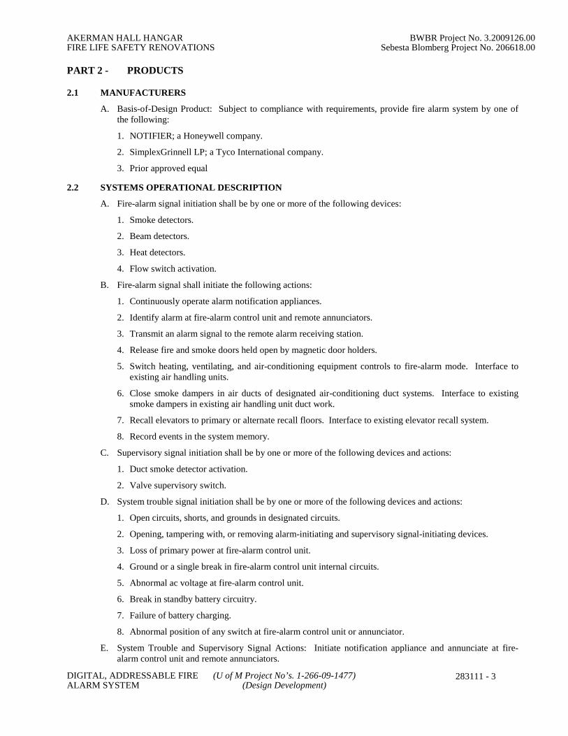
AKERMAN HALL HANGAR BWBR Project No. 3.2009126.00FIRE LIFE SAFETY RENOVATIONS Sebesta Blomberg Project No. 206618.00
DIGITAL, ADDRESSABLE FIRE (U of M Project No’s. 1-266-09-1477)ALARM SYSTEM (Design Development)
283111 - 3
PART 2 - PRODUCTS
2.1 MANUFACTURERS
A. Basis-of-Design Product: Subject to compliance with requirements, provide fire alarm system by one ofthe following:
1. NOTIFIER; a Honeywell company.
2. SimplexGrinnell LP; a Tyco International company.
3. Prior approved equal
2.2 SYSTEMS OPERATIONAL DESCRIPTION
A. Fire-alarm signal initiation shall be by one or more of the following devices:
1. Smoke detectors.
2. Beam detectors.
3. Heat detectors.
4. Flow switch activation.
B. Fire-alarm signal shall initiate the following actions:
1. Continuously operate alarm notification appliances.
2. Identify alarm at fire-alarm control unit and remote annunciators.
3. Transmit an alarm signal to the remote alarm receiving station.
4. Release fire and smoke doors held open by magnetic door holders.
5. Switch heating, ventilating, and air-conditioning equipment controls to fire-alarm mode. Interface toexisting air handling units.
6. Close smoke dampers in air ducts of designated air-conditioning duct systems. Interface to existingsmoke dampers in existing air handling unit duct work.
7. Recall elevators to primary or alternate recall floors. Interface to existing elevator recall system.
8. Record events in the system memory.
C. Supervisory signal initiation shall be by one or more of the following devices and actions:
1. Duct smoke detector activation.
2. Valve supervisory switch.
D. System trouble signal initiation shall be by one or more of the following devices and actions:
1. Open circuits, shorts, and grounds in designated circuits.
2. Opening, tampering with, or removing alarm-initiating and supervisory signal-initiating devices.
3. Loss of primary power at fire-alarm control unit.
4. Ground or a single break in fire-alarm control unit internal circuits.
5. Abnormal ac voltage at fire-alarm control unit.
6. Break in standby battery circuitry.
7. Failure of battery charging.
8. Abnormal position of any switch at fire-alarm control unit or annunciator.
E. System Trouble and Supervisory Signal Actions: Initiate notification appliance and annunciate at fire-alarm control unit and remote annunciators.

AKERMAN HALL HANGAR BWBR Project No. 3.2009126.00FIRE LIFE SAFETY RENOVATIONS Sebesta Blomberg Project No. 206618.00
DIGITAL, ADDRESSABLE FIRE (U of M Project No’s. 1-266-09-1477)ALARM SYSTEM (Design Development)
283111 - 4
2.3 SYSTEM SMOKE DETECTORS
A. General Requirements for System Smoke Detectors:
1. Comply with UL 268; operating at 24-V dc, nominal.
2. Integral Addressable Module: Arranged to communicate detector status (normal, alarm, or trouble) tofire-alarm control unit.
3. Base Mounting: Detector and associated electronic components shall be mounted in a twist-lockmodule that connects to a fixed base. Provide terminals in the fixed base for connection to buildingwiring.
4. Self-Restoring: Detectors do not require resetting or readjustment after actuation to restore them tonormal operation.
5. Integral Visual-Indicating Light: LED type indicating detector has operated.
B. Beam Detectors: Reflected beam some detectors. Consists of both transceivers and reflectors.
C. Duct Smoke Detectors: Photoelectric type complying with UL 268A.
1. Detector address shall be accessible from fire-alarm control unit and shall be able to identify thedetector's location within the system and its sensitivity setting.
2. An operator at fire-alarm control unit, having the designated access level, shall be able to manuallyaccess the following for each detector:
a. Primary status.b. Device type.c. Present average value.d. Present sensitivity selected.e. Sensor range (normal, dirty, etc.).
3. Weatherproof Duct Housing Enclosure: NEMA 250, Type 4X.
4. Each sensor shall have multiple levels of detection sensitivity.
5. Sampling Tubes: Design and dimensions as recommended by manufacturer for specific duct size, airvelocity, and installation conditions where applied.
6. Relay Fan Shutdown: Rated to interrupt fan motor-control circuit.
2.4 NOTIFICATION APPLIANCES
A. General Requirements for Notification Appliances: Connected to notification appliance signal circuits,zoned as indicated, equipped for mounting as indicated and with screw terminals for system connections.
1. Combination Devices: Factory-integrated audible and visible devices in a single-mounting assembly,equipped for mounting as indicated and with screw terminals for system connections.
B. Horns: Electric-vibrating-polarized type, 24-V dc; with provision for housing the operating mechanismbehind a grille. Comply with UL 464. Horns shall produce a sound-pressure level of 90 dBA, measured 10feet from the horn, using the coded signal prescribed in UL 464 test protocol.
C. Visible and Audible/Visual Notification Appliances: Xenon strobe lights comply with UL 1971, with clearor nominal white polycarbonate lens mounted on an aluminum faceplate. The word "FIRE" is engraved inminimum 1-inch- high letters on the lens.
1. Rated Light Output:
a. 15/30/75/110 cd, selectable in the field.
2. Mounting: Ceiling-mounted unless otherwise indicated.
3. For units with guards to prevent physical damage, light output ratings shall be determined with guardsin place.
4. Flashing shall be in a temporal pattern, synchronized with other units.

AKERMAN HALL HANGAR BWBR Project No. 3.2009126.00FIRE LIFE SAFETY RENOVATIONS Sebesta Blomberg Project No. 206618.00
DIGITAL, ADDRESSABLE FIRE (U of M Project No’s. 1-266-09-1477)ALARM SYSTEM (Design Development)
283111 - 5
5. Strobe Leads: Factory connected to screw terminals.
6. Mounting Faceplate: Factory finished, red.
2.5 MAGNETIC DOOR HOLDERS
A. Description: Units are equipped for wall or floor mounting as indicated and are complete with matchingdoorplate.
1. Electromagnet: Requires no more than 3 W to develop 25-lbf holding force.
2. Wall-Mounted Units: Flush mounted unless otherwise indicated.
3. Rating: 24-V dc.
B. Material and Finish: Match door hardware.
2.6 ADDRESSABLE INTERFACE DEVICE
A. Description: Microelectronic monitor module, UL listed for use in providing a system address for alarm-initiating devices for wired applications with normally open contacts.
B. Integral Relay: Capable of providing a direct signal to elevator controller to initiate elevator recall
PART 3 - EXECUTION
3.1 EQUIPMENT INSTALLATION
A. Comply with NFPA 72 for installation of fire-alarm equipment.
B. Connecting to Existing Equipment: Verify that existing fire-alarm system is operational before makingchanges or connections.
1. Connect new equipment to new control panel provided under separate contract.
C. Duct Smoke Detectors: Comply with NFPA 72 and NFPA 90A. Install sampling tubes so they extend thefull width of duct.
D. Fire-Alarm Control Unit: Surface mounted, with tops of cabinets not more than 72 inches above thefinished floor.
E. Annunciator: Install with top of panel not more than 72 inches above the finished floor.
3.2 CONNECTIONS
A. For fire-protection systems related to doors in fire-rated walls and partitions and to doors in smokepartitions, comply with requirements in Division 08 Section "Door Hardware." Connect hardware anddevices to fire-alarm system.
1. Verify that hardware and devices are UL listed for use with fire-alarm system in this Section beforemaking connections.
B. Make addressable connections with a supervised interface device to the following devices and systems.Install the interface device less than 3 feet from the device controlled. Make an addressable confirmationconnection when such feedback is available at the device or system being controlled.
1. Existing smoke dampers in air ducts of designated air-conditioning duct systems.
2. Alarm-initiating connection to elevator recall system and components.
3. Supervisory connections at valve supervisory switches.
4. Supervisory connections at low-air-pressure switch of each dry-pipe sprinkler system.

AKERMAN HALL HANGAR BWBR Project No. 3.2009126.00FIRE LIFE SAFETY RENOVATIONS Sebesta Blomberg Project No. 206618.00
DIGITAL, ADDRESSABLE FIRE (U of M Project No’s. 1-266-09-1477)ALARM SYSTEM (Design Development)
283111 - 6
3.3 IDENTIFICATION
A. Identify system components, wiring, cabling, and terminals. Comply with requirements for identificationspecified in Division 26 Section "Identification for Electrical Systems."
B. Install framed instructions in a location visible from fire-alarm control unit.
3.4 GROUNDING
A. Ground fire-alarm control unit and associated circuits; comply with IEEE 1100. Install a ground wire frommain service ground to fire-alarm control unit.
3.5 FIELD QUALITY CONTROL
A. Field tests shall be witnessed by authorities having jurisdiction
B. Perform tests and inspections.
C. Tests and Inspections:
1. Visual Inspection: Conduct visual inspection prior to testing.
a. Inspection shall be based on completed Record Drawings and system documentation that is required byNFPA 72 in its "Completion Documents, Preparation" Table in the "Documentation" Section of the"Fundamentals of Fire Alarm Systems" Chapter.
b. Comply with "Visual Inspection Frequencies" Table in the "Inspection" Section of the "Inspection,Testing and Maintenance" Chapter in NFPA 72; retain the "Initial/Reacceptance" column and list onlythe installed components.
2. System Testing: Comply with "Test Methods" Table in the "Testing" Section of the "Inspection,Testing and Maintenance" Chapter in NFPA 72.
3. Factory-authorized service representative shall prepare the "Fire Alarm System Record of Completion"in the "Documentation" Section of the "Fundamentals of Fire Alarm Systems" Chapter in NFPA 72 andthe "Inspection and Testing Form" in the "Records" Section of the "Inspection, Testing andMaintenance" Chapter in NFPA 72.
D. Reacceptance Testing: Perform reacceptance testing to verify the proper operation of added or replaceddevices and appliances.
E. Fire-alarm system will be considered defective if it does not pass tests and inspections.
F. Prepare test and inspection reports.
G. Maintenance Test and Inspection: Perform tests and inspections listed for weekly, monthly, quarterly, andsemiannual periods. Use forms developed for initial tests and inspections.
H. Annual Test and Inspection: One year after date of Substantial Completion, test fire-alarm systemcomplying with visual and testing inspection requirements in NFPA 72. Use forms developed for initialtests and inspections.
END OF SECTION 28 31 11