Embed Size (px)
Citation preview
INTERIM MEASURE WORK PLAN
Phibro-Tech, Inc.
Santa Fe Springs, California
July 15, 2015
Prepared for:
Phibro-Tech, Inc.
8851 Dice Road
Santa Fe Springs, California 90670
Prepared by:
IRIS ENVIRONMENTAL 1438 Webster Street, Suite 302
Oakland, California 94612
Project No. 06-441-V
Interim Measure Work Plan July 15, 2015
Phibro-Tech, Inc., Santa Fe Springs, CA
i IRIS ENVIRONMENTAL
TABLE OF CONTENTS
Table of Contents ............................................................................................................................. i 1.0 Introduction ......................................................................................................................... 1 2.0 INTERIM REMEDIAL MEASURES OVERVIEW .......................................................... 2
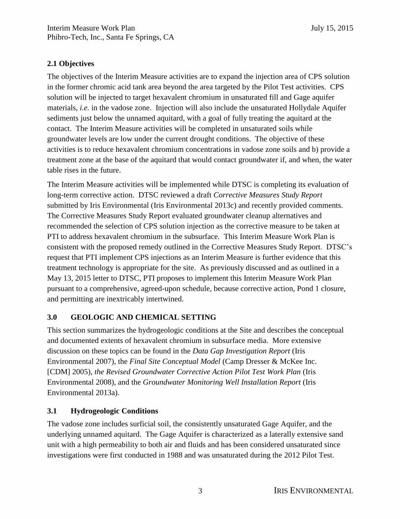
2.1 Objectives ............................................................................................................................. 3 3.0 Geologic and Chemical Setting .......................................................................................... 3
3.1 Hydrogeologic Conditions .............................................................................................. 3 3.2 Extent of Hexavalent Chromium in Soils ....................................................................... 4
4.0 Summary of Pilot Test Results ........................................................................................... 4
4.1 Physical Pilot Test Results .............................................................................................. 5
4.1.1 Gage Aquifer ............................................................................................................. 5
4.1.2 Unnamed Aquitard .................................................................................................... 5
4.1.3 Upper Hollydale Aquifer .......................................................................................... 5 4.2 Chemical Findings .......................................................................................................... 6
5.0 Interim Measure Activities ................................................................................................. 6
5.1 Site Preparation ............................................................................................................... 6 5.2 Injection Methods ........................................................................................................... 7
5.3 Injection Zones................................................................................................................ 7 5.3.1 Gage Aquifer ............................................................................................................. 8 5.3.2 Unnamed Aquitard Injection..................................................................................... 8
5.3.3 Upper Hollydale Aquifer .......................................................................................... 8 5.4 Process and Performance Monitoring ............................................................................. 9
6.0 Data Evaluation ................................................................................................................... 9 6.1 Data Quality Objectives .................................................................................................. 9
6.2 Quality Assurance / Quality Control Requirements ..................................................... 10 6.2.1 Duplicate Samples .................................................................................................. 10
6.2.2 Field Instrument Calibration ................................................................................... 10 6.3 Reporting....................................................................................................................... 10
7.0 Project Management ......................................................................................................... 10 7.1 Staffing .......................................................................................................................... 10 7.2 Schedule ........................................................................................................................ 10 7.3 Health and Safety .......................................................................................................... 11 7.4 Residuals Management ................................................................................................. 11
8.0 References ......................................................................................................................... 12
List of Figures
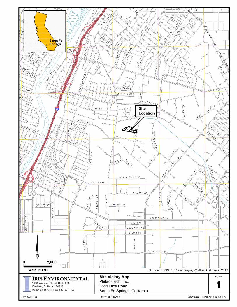
Figure 1. Site Vicinity Map
Figure 2. Interim Measure Calcium Polysulfide Injection Area
Figure 3. Interim Measure Borehole Locations

Interim Measure Work Plan July 15, 2015
Phibro-Tech, Inc., Santa Fe Springs, CA
ii IRIS ENVIRONMENTAL
List of Tables
Table 1. Proposed Boreholes
Table 2. Calcium Polysulfide Solution Injection Calculations

Interim Measure Work Plan July 15, 2015
Phibro-Tech, Inc., Santa Fe Springs, CA
1 IRIS ENVIRONMENTAL
1.0 INTRODUCTION
Pursuant to part V, section E.13.b of the Hazardous Waste Facility Permit 1995 Corrective
Action Permit Modification and section 5.3 of the Corrective Action Consent Order dated
February 22, 2012, this Interim Remedial Measures Work Plan (Work Plan) describes the
interim injection activities voluntarily proposed as part of the soil and alternative groundwater
corrective action program being conducted at the Phibro-Tech, Inc. (PTI) facility located at 8851
Dice Road, Santa Fe Springs, California (Site, Figure 1).
PTI implemented a calcium polysulfide (CPS) solution interim Pilot Test in 2012 to treat
impacted vadose zone soils and dissolved hexavalent chromium in groundwater. The Pilot Test
was successful in reducing hexavalent chromium to trivalent chromium in source soils, and
completely mitigated all chromium in groundwater to below drinking water standards (Interim
Soil Corrective Action Pilot Test Report (Iris Environmental 2012) and Groundwater Corrective
Action Pilot Test Report (Iris Environmental 2013b)). Because of the pilot test’s success, the
Department of Toxic Substances Control (DTSC) indicated it would consider a permit
modification to change the treatment technology from groundwater extraction and treatment, as
reflected in the facility’s 1995 Corrective Action Permit Modification.
The reevaluation of the treatment technology was also warranted because technology
advancements and the state of the practice have evolved to include many “in situ” remediation
technologies that are more effective and more cost-efficient in treating hexavalent chromium and
VOCs in groundwater compared to traditional pump and treat systems. While groundwater
pump and treat can be effective at controlling further migration of dissolved contaminants in
groundwater, it is inefficient at remediating impacted groundwater and vadose zone sources, is
unsustainable based on current science, and is expensive to implement and operate over the long
term.
A draft Corrective Measures Study (CMS) report was submitted to DTSC in December 2013
proposing CPS solution injection as an alternative to groundwater extraction and treatment.
DTSC reviewed and provided comments to PTI on September 5, 2014. A revised CMS is
currently in preparation. In a May 1, 2015 letter to PTI (Interim Measure, Calcium Polysulfide
Injection in Soil, Chromic Acid Tank Area), DTSC requested that PTI undertake an interim
measure now to fixate hexavalent chromium in the assumed source area (specifically unsaturated
soils or “vadose zone”). A Work Plan responding to that request was submitted on June 1, 2015.
DTSC provided comments in a letter to PTI on June 15, 2015. This version of the work plan
addresses those comments. It is important to note that quarterly groundwater monitoring
consistently demonstrates that constituents of concern are at or below background concentrations
at the facility’s point of compliance and boundary wells and that there is no immediate threat to
the environment.

Interim Measure Work Plan July 15, 2015
Phibro-Tech, Inc., Santa Fe Springs, CA
2 IRIS ENVIRONMENTAL
2.0 INTERIM REMEDIAL MEASURES OVERVIEW
The activities discussed herein will be conducted using similar methods to the May 29, 2008
Revised Groundwater Corrective Action Pilot Test Work Plan submitted to DTSC and approved
June 27, 2008. The completed Pilot Test activities and the Interim Measure activities described
in this Work Plan consist of the injection of a CPS solution to stabilize hexavalent chromium in
Site soils. For background on the CPS injection assumptions and development, refer to the 2008
Pilot Test Work Plan and completion reports (Iris Environmental 2008, 2012, 2013b).
The Interim Measure activities will be conducted in the vicinity of the former chromic acid
underground storage tank that was removed in or around 1981 (Figure 2) and adjacent to the
Pilot Test injection area, in the vicinity of groundwater monitoring wells MW-4 and MW-9. The
Interim Measure activities will target unsaturated soil where hexavalent chromium is known to
be present in soil. The 45-foot thick target injection zone will extend from approximately 10 to
55 feet bgs and is composed of three vadose zone units plus the upper portion of the unsaturated
Hollydale Aquifer. The top layer is fill, which extends to 15 to 20 feet below ground surface
(bgs). The Gage Aquifer is an unsaturated sand layer and extends below the fill to
approximately 30 feet bgs. Below the Gage Aquifer is an unnamed aquitard of silt and clay,
which extends to 50 feet bgs. Below the unnamed aquitard is the upper Hollydale Aquifer,
which extends between approximately 50 and 150 feet bgs. While it is typically a fully saturated
aquifer, the upper Hollydale Aquifer sediments are currently unsaturated from the bottom of the
unnamed aquitard to a depth of approximately 75 feet bgs due to drought conditions. The top 5
feet of the unsaturated upper Hollydale Aquifer will be included in the target injection zone. The
Interim Measure activities will fixate hexavalent chromium in Site vadose zone soils near the
former chromic acid tank by injecting CPS solution into these three units. Injection into the
unsaturated Hollydale Aquifer sediments has been included as additional assurance that the base
of the aquitard is included in the fixation treatment.
To fill a remaining data gap and further delineate the presence of hexavalent chromium in soils
in the southern portion of the Interim Measure area, baseline soil borings will be advanced prior
to the initiation of injection activities at the locations shown on Figure 3. Soil samples will be
collected and analyzed for VOCs, Title 22 (CAM-17) metals, and hexavalent chromium. The
target zone of injection may be modified based on the analytical results (Table 1).
To confirm the CPS solution has been distributed throughout the subsurface as expected, a test
boring will be advanced shortly after the injection program begins to verify the assumed radius
of influence (ROI) in each geologic unit. Soil test borings will also be advanced after the entire
program has been completed to assess evidence of hexavalent chromium fixation. Soil cores
from all sampling events will be visually inspected and soil samples will be collected from
approximately every five feet of soil core for laboratory analytical testing to confirm the success
of the injection.
Interim Measure Work Plan July 15, 2015
Phibro-Tech, Inc., Santa Fe Springs, CA
3 IRIS ENVIRONMENTAL
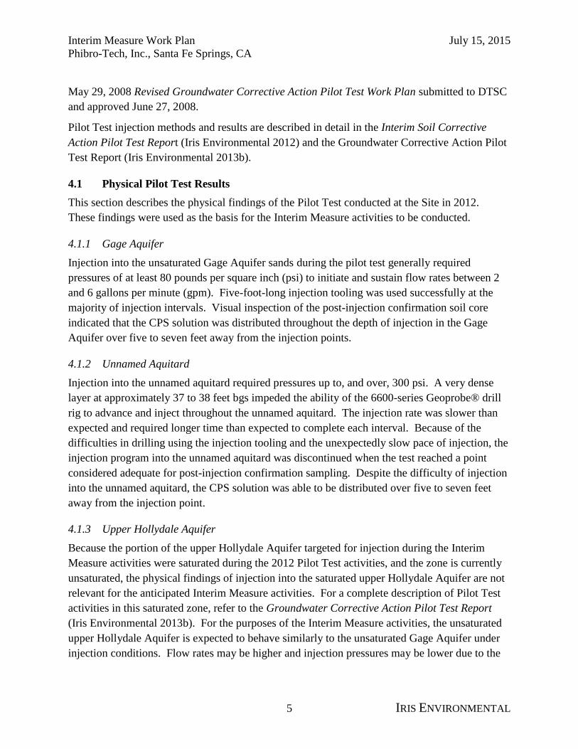
2.1 Objectives
The objectives of the Interim Measure activities are to expand the injection area of CPS solution
in the former chromic acid tank area beyond the area targeted by the Pilot Test activities. CPS
solution will be injected to target hexavalent chromium in unsaturated fill and Gage aquifer
materials, i.e. in the vadose zone. Injection will also include the unsaturated Hollydale Aquifer
sediments just below the unnamed aquitard, with a goal of fully treating the aquitard at the
contact. The Interim Measure activities will be completed in unsaturated soils while
groundwater levels are low under the current drought conditions. The objective of these
activities is to reduce hexavalent chromium concentrations in vadose zone soils and b) provide a
treatment zone at the base of the aquitard that would contact groundwater if, and when, the water
table rises in the future.
The Interim Measure activities will be implemented while DTSC is completing its evaluation of
long-term corrective action. DTSC reviewed a draft Corrective Measures Study Report
submitted by Iris Environmental (Iris Environmental 2013c) and recently provided comments.
The Corrective Measures Study Report evaluated groundwater cleanup alternatives and
recommended the selection of CPS solution injection as the corrective measure to be taken at
PTI to address hexavalent chromium in the subsurface. This Interim Measure Work Plan is
consistent with the proposed remedy outlined in the Corrective Measures Study Report. DTSC’s
request that PTI implement CPS injections as an Interim Measure is further evidence that this
treatment technology is appropriate for the site. As previously discussed and as outlined in a
May 13, 2015 letter to DTSC, PTI proposes to implement this Interim Measure Work Plan
pursuant to a comprehensive, agreed-upon schedule, because corrective action, Pond 1 closure,
and permitting are inextricably intertwined.
3.0 GEOLOGIC AND CHEMICAL SETTING
This section summarizes the hydrogeologic conditions at the Site and describes the conceptual
and documented extents of hexavalent chromium in subsurface media. More extensive
discussion on these topics can be found in the Data Gap Investigation Report (Iris
Environmental 2007), the Final Site Conceptual Model (Camp Dresser & McKee Inc.
[CDM] 2005), the Revised Groundwater Corrective Action Pilot Test Work Plan (Iris
Environmental 2008), and the Groundwater Monitoring Well Installation Report (Iris
Environmental 2013a).
3.1 Hydrogeologic Conditions
The vadose zone includes surficial soil, the consistently unsaturated Gage Aquifer, and the
underlying unnamed aquitard. The Gage Aquifer is characterized as a laterally extensive sand
unit with a high permeability to both air and fluids and has been considered unsaturated since
investigations were first conducted in 1988 and was unsaturated during the 2012 Pilot Test.

Interim Measure Work Plan July 15, 2015
Phibro-Tech, Inc., Santa Fe Springs, CA
4 IRIS ENVIRONMENTAL
The underlying unnamed aquitard is a hard, dense, fine grained unit that consists of silts, clays
and fine sand with occasional silty sand and thin sandy silt lenses. These sediments have a low
hydraulic conductivity (1.64x10⁻⁷
to 1.03x10⁻⁵
centimeters per second [cm/s]), low permeability
to air (0.309 to 125 millidarcies), high porosity (30 to 49%), and moderate moisture content. The
lithology and contacts of the Gage Aquifer and unnamed aquitard are found to be similar in all
boreholes in the former chromic acid tank area.
The upper Hollydale Aquifer occurs below the unnamed aquitard and extends from typical
depths of 50 to 55 feet bgs to approximately 150 feet bgs. The upper Hollydale Aquifer consists
primarily of coarse to fine sand with high hydraulic conductivity and high porosity. This unit
has historically been saturated, but due to drought conditions the top 25 feet of the aquifer are
currently unsaturated, i.e. from approximately 50 to 75 feet bgs. The upper Hollydale Aquifer is
considered to be lithologically similar across the Site (Iris Environmental 2007).
3.2 Extent of Hexavalent Chromium in Soils
The current conceptual model for the distribution of hexavalent chromium assumes that releases
from the suspected former chromic acid tank potentially migrated directly under the tank through
the Gage Aquifer to the top of the unnamed aquitard and spread laterally in a primarily
southwestern direction along the Gage Aquifer/unnamed aquitard contact. Hexavalent
chromium in the releases appears to have sorbed into the unnamed aquitard to varying depths.
At the source area beneath the former chromic acid tank, hexavalent chromium has been detected
down to the interface of the aquitard and the underlying upper Hollydale Aquifer. Historical soil
data suggest that releases may have also originated from the former Pond 1 containment,
however the work necessary to complete the investigation is pending former Pond 1 closure
activities.
Based on data presented in the Data Gap Investigation Report (Iris Environmental 2007), the
Final Site Conceptual Model (CDM 2005), and the Interim Soil Corrective Action Pilot Test
Report (Iris Environmental 2012), the distribution of hexavalent chromium in vadose zone soils
is considered to be concentrated mostly in the vicinity of the suspected former chromic acid tank
(near monitoring well MW-18S and borehole SB-7). For that reason, Pilot Test CPS solution
injection activities were focused in this area. Interim Measure injection locations will expand the
Pilot Test injection area laterally to the accessible areas to the north and south. The Interim
Measure target injection zone will extend from 10 to 55 feet bgs, or to the depth that can be
reached with the injection methods and tooling proposed.
4.0 SUMMARY OF PILOT TEST RESULTS
Pilot Test activities to stabilize hexavalent chromium consisted of injecting CPS solution into the
vadose zone (Gage Aquifer and unnamed aquitard) during one injection event, and injecting CPS
solution into groundwater in the saturated upper Hollydale Aquifer during two subsequent
injection events (Phase I and II). The Pilot Test activities were conducted pursuant to the
Interim Measure Work Plan July 15, 2015
Phibro-Tech, Inc., Santa Fe Springs, CA
5 IRIS ENVIRONMENTAL
May 29, 2008 Revised Groundwater Corrective Action Pilot Test Work Plan submitted to DTSC
and approved June 27, 2008.
Pilot Test injection methods and results are described in detail in the Interim Soil Corrective
Action Pilot Test Report (Iris Environmental 2012) and the Groundwater Corrective Action Pilot
Test Report (Iris Environmental 2013b).
4.1 Physical Pilot Test Results
This section describes the physical findings of the Pilot Test conducted at the Site in 2012.
These findings were used as the basis for the Interim Measure activities to be conducted.
4.1.1 Gage Aquifer
Injection into the unsaturated Gage Aquifer sands during the pilot test generally required
pressures of at least 80 pounds per square inch (psi) to initiate and sustain flow rates between 2
and 6 gallons per minute (gpm). Five-foot-long injection tooling was used successfully at the
majority of injection intervals. Visual inspection of the post-injection confirmation soil core
indicated that the CPS solution was distributed throughout the depth of injection in the Gage
Aquifer over five to seven feet away from the injection points.
4.1.2 Unnamed Aquitard
Injection into the unnamed aquitard required pressures up to, and over, 300 psi. A very dense
layer at approximately 37 to 38 feet bgs impeded the ability of the 6600-series Geoprobe® drill
rig to advance and inject throughout the unnamed aquitard. The injection rate was slower than
expected and required longer time than expected to complete each interval. Because of the
difficulties in drilling using the injection tooling and the unexpectedly slow pace of injection, the
injection program into the unnamed aquitard was discontinued when the test reached a point
considered adequate for post-injection confirmation sampling. Despite the difficulty of injection
into the unnamed aquitard, the CPS solution was able to be distributed over five to seven feet
away from the injection point.
4.1.3 Upper Hollydale Aquifer
Because the portion of the upper Hollydale Aquifer targeted for injection during the Interim
Measure activities were saturated during the 2012 Pilot Test activities, and the zone is currently
unsaturated, the physical findings of injection into the saturated upper Hollydale Aquifer are not
relevant for the anticipated Interim Measure activities. For a complete description of Pilot Test
activities in this saturated zone, refer to the Groundwater Corrective Action Pilot Test Report
(Iris Environmental 2013b). For the purposes of the Interim Measure activities, the unsaturated
upper Hollydale Aquifer is expected to behave similarly to the unsaturated Gage Aquifer under
injection conditions. Flow rates may be higher and injection pressures may be lower due to the
Interim Measure Work Plan July 15, 2015
Phibro-Tech, Inc., Santa Fe Springs, CA
6 IRIS ENVIRONMENTAL
slightly coarser material generally observed in the upper Hollydale Aquifer when compared to
the Gage Aquifer.
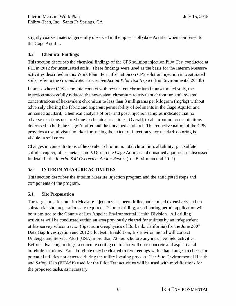
4.2 Chemical Findings
This section describes the chemical findings of the CPS solution injection Pilot Test conducted at
PTI in 2012 for unsaturated soils. These findings were used as the basis for the Interim Measure
activities described in this Work Plan. For information on CPS solution injection into saturated
soils, refer to the Groundwater Corrective Action Pilot Test Report (Iris Environmental 2013b)
In areas where CPS came into contact with hexavalent chromium in unsaturated soils, the
injection successfully reduced the hexavalent chromium to trivalent chromium and lowered
concentrations of hexavalent chromium to less than 3 milligrams per kilogram (mg/kg) without
adversely altering the fabric and apparent permeability of sediments in the Gage Aquifer and
unnamed aquitard. Chemical analysis of pre- and post-injection samples indicates that no
adverse reactions occurred due to chemical reactions. Overall, total chromium concentrations
decreased in both the Gage Aquifer and the unnamed aquitard. The reductive nature of the CPS
provides a useful visual marker for tracing the extent of injection since the dark coloring is
visible in soil cores.
Changes in concentrations of hexavalent chromium, total chromium, alkalinity, pH, sulfate,
sulfide, copper, other metals, and VOCs in the Gage Aquifer and unnamed aquitard are discussed
in detail in the Interim Soil Corrective Action Report (Iris Environmental 2012).
5.0 INTERIM MEASURE ACTIVITIES
This section describes the Interim Measure injection program and the anticipated steps and
components of the program.
5.1 Site Preparation
The target area for Interim Measure injections has been drilled and studied extensively and no
substantial site preparations are required. Prior to drilling, a soil boring permit application will
be submitted to the County of Los Angeles Environmental Health Division. All drilling
activities will be conducted within an area previously cleared for utilities by an independent
utility survey subcontractor (Spectrum Geophysics of Burbank, California) for the June 2007
Data Gap Investigation and 2012 pilot test. In addition, Iris Environmental will contact
Underground Service Alert (USA) more than 72 hours before any intrusive field activities.
Before advancing borings, a concrete cutting contractor will core concrete and asphalt at all
borehole locations. Each borehole may be cleared to five feet bgs with a hand auger to check for
potential utilities not detected during the utility locating process. The Site Environmental Health
and Safety Plan (EHASP) used for the Pilot Test activities will be used with modifications for
the proposed tasks, as necessary.

Interim Measure Work Plan July 15, 2015
Phibro-Tech, Inc., Santa Fe Springs, CA
7 IRIS ENVIRONMENTAL
A Site-wide Waste Discharge Requirement (WDR) permit is required from the California
Regional Water Quality Control Board Los Angeles Region (LARWQCB) for in-situ soil and
groundwater remedial activities at the Site, including in-situ chemical reduction of hexavalent
chromium. Iris Environmental obtained a WDR permit from for the Pilot Test activities and is in
discussions with the LARWQCB about amending the existing permit to include the interim
measure activities. The LARWQCB requires that this Work Plan be approved by DTSC before a
modified WDR permit can be issued.
5.2 Injection Methods
To treat hexavalent chromium in vadose zone soils, 25 injection boreholes will be advanced to
expand the Pilot Test injection area. Borehole locations have been chosen to address distributed
impacts from the assumed former chromic acid tank releases. Injection points will be advanced
approximately 15-feet on-center (Figure 3) within the CPS solution injection area.
An 8040-series Geoprobe® truck-mounted, direct-push drill rig will be used to advance small-
diameter stainless steel injection rods (a larger rig than used in the Pilot Test). At each target
depth, the drive rod will be retracted to expose the five-, two-, or one-foot injection interval of
the rod. The injection interval used will vary based on field performance of the injection tooling.
The target volume of CPS solution to be injected at each interval will vary based on the
stratigraphic unit being targeted (Table 2). Following injection of the target CPS solution
volume into the treatment interval, the injection tooling will be advanced to the next treatment
interval. The remaining CPS solution will be injected incrementally such that the whole target
zone is treated in a step-wise fashion from top to bottom with approximately equal volumes of
CPS solution being injected at each interval of each injection zone.
The CPS solution injected into the treatment zone will be mixed to a dosage concentration of 5%
by volume. The CPS solution will be injected using a progressive cavity pump with a flow rate
of up to 100 gpm and pressure up to approximately 800 psi.
After injection, the boreholes will be grouted with neat cement and bentonite and the surface seal
constructed with like materials.
5.3 Injection Zones
Three injection zones will be targeted at each borehole: unsaturated fill materials and the upper
silty sand and sand of the Gage Aquifer, extending from 10 feet bgs to 30 feet bgs; the unnamed
aquitard extending from approximately 30 to 50 feet bgs; and the upper 5 feet of the upper
Hollydale Aquifer extending from approximately 50 to 55 feet bgs. The design parameters
considered for each zone are described below.
The CPS solution volumes were developed using an assumed radius of influence of 7.5 feet, a
laboratory-measured porosity of 0.41 for sands and 0.84 for silts/clay, and an assumed pore fluid
saturation of 75%. Complete displacement of the existing pore fluids by the CPS solution is

Interim Measure Work Plan July 15, 2015
Phibro-Tech, Inc., Santa Fe Springs, CA
8 IRIS ENVIRONMENTAL
considered structurally impossible; therefore, the estimated volumes stated below will be
considered to be the upper bound volume used to terminate injection at each location. It is
anticipated that a somewhat lower volumes of reactant will be injected. However, adequate
quantities of CPS solution will be stored on-site so that injection can continue if more than
estimated quantities of CPS solution can be injected.
5.3.1 Gage Aquifer
The treatment zone in the surficial soils and Gage Aquifer is a 20-foot thick zone of silty sand
and sand that ranges from approximately 10 to 30 feet bgs. The injection rods will be advanced
step-wise to the base of the Gage Aquifer.
The estimated volume of CPS solution injected is based on aquifer characteristics,
implementation knowledge gained during Pilot Test activities, and assumptions made about CPS
solution concentration. In the surficial soils and Gage Aquifer, approximately 135 gallons (gal)
of CPS solution at 5% concentration will be injected per foot of the 20-foot injection interval.
This results in a total volume of CPS solution at 5% of approximately 2,700 gal per boring. To
provide 2,700 gal of CPS solution, approximately 470 gal of CPS solution at a stock
concentration of 29% will be diluted.
5.3.2 Unnamed Aquitard Injection
The treatment zone in the unnamed aquitard is a 20-foot thick zone of fine-grained material that
ranges from approximately 30 to 50 feet bgs. Approximately 122 gal of CPS solution at 5%
concentration will be injected per foot of the 20-foot injection interval. This results in a total
volume of CPS solution at 5% of approximately 2,450 gal per boring. To provide 2,450 gal of
CPS solution, approximately 425 gal of CPS solution at a stock concentration of 29% will be
diluted.
5.3.3 Upper Hollydale Aquifer
The target treatment zone in the upper Hollydale Aquifer is a five-foot thick unsaturated zone
underlying the unnamed aquitard from approximately 50 to 55 feet bgs. The injection rods will
be advanced approximately 5 feet beyond the base of the unnamed aquitard, which is located at
approximately 50 feet bgs (based on the geology recorded during Pilot Test activities). For the
purposes of these Interim Measure activities, the upper Hollydale Aquifer sediments are assumed
to behave similarly to the unsaturated Gage Aquifer sediments. Approximately 135 gal of CPS
solution at 5% concentration will be injected per foot of the 5-foot injection interval. This results
in a total volume of CPS solution at 5% of approximately 680 gal per boring. To provide 680 gal
of CPS solution, approximately 120 gal of CPS solution at a stock concentration of 29% will be
diluted.

Interim Measure Work Plan July 15, 2015
Phibro-Tech, Inc., Santa Fe Springs, CA
9 IRIS ENVIRONMENTAL
5.4 Process and Performance Monitoring
Process monitoring will be conducted for the Gage Aquifer, unnamed aquitard, and unsaturated
upper Hollydale Aquifer by collecting discrete soil samples after the first four adjacent borings
are injected. At the midpoint of the four initial injection points, one borehole will be advanced to
perform visual logging, and to collect discrete soil samples, which will be used to confirm the
anticipated ROI has been achieved. Soil samples will be collected no earlier than three days
following injection, based on the results of the bench scale treatability study (Spectrum
Analytical 2007). The visual and chemical results from the process boring will be used to adjust
spacing as necessary for the remaining injection borings. For final performance verification
sampling, additional boreholes are proposed at select locations within and beyond the limit of the
injection borehole grid to quantify the lateral extent of injection influence and reduction of
hexavalent chromium (Figure 3).
All soil samples will be collected using a direct push drill rig operated by Vironex in general
accordance with the methods detailed in the Revised Groundwater Corrective Action Pilot Test
Work Plan (Iris Environmental 2008). Soil samples will be submitted for analysis of VOCs,
Title 22 (CAM-17) metals, and hexavalent chromium. A summary of the soil analytical program
is presented on Table 1.
6.0 DATA EVALUATION
The data evaluation section describes the data quality objectives, Quality Assurance/Quality
Control (QA/QC) methods, data interpretation procedures, and reporting.
6.1 Data Quality Objectives
Data Quality Objectives (DQOs) are qualitative and quantitative statements that specify the
quality of the data required to support decisions made during testing activities. DQOs are based
on the end uses of the data to be collected.
For these interim measure activities, the test objectives will be achieved through the collection
and use of screening level data and definitive data. A visual assessment of soil cores will
provide screening level data that can be used to rapidly identify and quantify injection
performance and fixation of hexavalent chromium, although the quantification can be relatively
imprecise. The interim measure objectives will be achieved primarily by using off-site
laboratory analytical data for precise assessments of hexavalent chromium fixation. Laboratory
analyses will use the same USEPA methods and have the same laboratory reporting limits for the
chemicals of concern as used in the Data Gap Investigation Report (Iris Environmental 2007)
and in the Interim Soil Corrective Action Pilot Test Report (Iris Environmental 2012).
Interim Measure Work Plan July 15, 2015
Phibro-Tech, Inc., Santa Fe Springs, CA
10 IRIS ENVIRONMENTAL
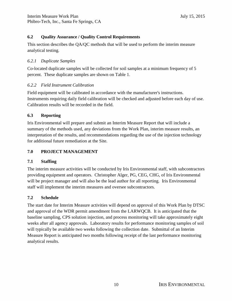
6.2 Quality Assurance / Quality Control Requirements
This section describes the QA/QC methods that will be used to perform the interim measure
analytical testing.
6.2.1 Duplicate Samples
Co-located duplicate samples will be collected for soil samples at a minimum frequency of 5
percent. These duplicate samples are shown on Table 1.
6.2.2 Field Instrument Calibration
Field equipment will be calibrated in accordance with the manufacturer's instructions.
Instruments requiring daily field calibration will be checked and adjusted before each day of use.
Calibration results will be recorded in the field.
6.3 Reporting
Iris Environmental will prepare and submit an Interim Measure Report that will include a
summary of the methods used, any deviations from the Work Plan, interim measure results, an
interpretation of the results, and recommendations regarding the use of the injection technology
for additional future remediation at the Site.
7.0 PROJECT MANAGEMENT
7.1 Staffing
The interim measure activities will be conducted by Iris Environmental staff, with subcontractors
providing equipment and operators. Christopher Alger, PG, CEG, CHG, of Iris Environmental
will be project manager and will also be the lead author for all reporting. Iris Environmental
staff will implement the interim measures and oversee subcontractors.
7.2 Schedule
The start date for Interim Measure activities will depend on approval of this Work Plan by DTSC
and approval of the WDR permit amendment from the LARWQCB. It is anticipated that the
baseline sampling, CPS solution injection, and process monitoring will take approximately eight
weeks after all agency approvals. Laboratory results for performance monitoring samples of soil
will typically be available two weeks following the collection date. Submittal of an Interim
Measure Report is anticipated two months following receipt of the last performance monitoring
analytical results.

Interim Measure Work Plan July 15, 2015
Phibro-Tech, Inc., Santa Fe Springs, CA
11 IRIS ENVIRONMENTAL
7.3 Health and Safety
Site health and safety procedures will conform to the current Site EHASP as modified for the
proposed tasks. It is anticipated that the pilot testing can be completed using Level D personal
protection.
7.4 Residuals Management
All soil cuttings will be drummed and disposed of following the receipt of analytical results.
Any water derived from equipment decontamination procedures will be recycled on-site in
accordance with the Revised Water Quality Sampling and Analysis Plan (Iris
Environmental 2014).
Interim Measure Work Plan July 15, 2015
Phibro-Tech, Inc., Santa Fe Springs, CA
12 IRIS ENVIRONMENTAL
8.0 REFERENCES
Camp Dresser & McKee Inc. (CDM). 2005. Final Site Conceptual Model. Phibro-Tech, Inc.,
Santa Fe Springs, California. March 9.
Spectrum Analytical. 2007. Treatability Report. September 24.
Iris Environmental. 2007. Data Gap Investigation Report, Phibro-Tech, Inc., Santa Fe Springs,
California. August 15.
Iris Environmental. 2008. Revised Groundwater Corrective Action Pilot Test Work Plan,
Phibro-Tech, Inc., Santa Fe Springs, California. May 29.
Iris Environmental. 2012. Interim Soil Corrective Action Pilot Test Report, Phibro-Tech, Inc.,
Santa Fe Springs, California. October 8.
Iris Environmental. 2013a. Groundwater Monitoring Well Installation Report, Phibro-Tech,
Inc., Santa Fe Springs, California. December 9.
Iris Environmental. 2013b. Groundwater Corrective Action Pilot Test Report, Phibro-Tech,
Inc., Santa Fe Springs, California. July 1.
Iris Environmental. 2013c. Corrective Measures Study Report, Phibro-Tech, Inc., Santa Fe
Springs, California. Draft.
Iris Environmental. 2014. Revised Water Quality Sampling and Analysis Plan, Phibro-Tech,
Inc., Santa Fe Springs, California. March 31.

Interim Measure Work Plan July 15, 2015
Phibro-Tech, Inc., Santa Fe Springs, CA
IRIS ENVIRONMENTAL
Figures
N
Santa Fe
Springs
1
Figure
Contract Number:Date:Drafter:
1438 Webster Street, Suite 302
Oakland, California 94612
Ph. (510) 834-4747 Fax: (510) 834-4199
RISI NVIRONMENTALE
EC 09/15/14 06-441-V
Site Vicinty Map
Phibro-Tech, Inc.
8851 Dice Road
Santa Fe Springs, California
Site
Location
Source: USGS 7.5' Quadrangle, Whittier, California, 2012

2
NSCALE IN FEET
0 80
Figure
Contract Number:Date:Drafter:
1438 Webster Street, Suite 302
Oakland, California 94612
Ph. (510) 834-4747 Fax: (510) 834-4199
RISI NVIRONMENTALE
EBH/AJW 05/29/15 06-441-V
LEGEND:
Interim Measure Injection
Area Boundary
Property Boundary
Interim Measure Injection Area
Phibro-Tech, Inc.
8851 Dice Road
Santa Fe Springs, California

3
Figure
1438 Webster Street, Suite 302
Oakland, California 94612
Ph. (510) 834-4747 Fax: (510) 834-4199
RIS
Drafter: Date: Contract Number:
I NVIRONMENTALE
06/25/15 06-441VEBH/AJW
Interim Measure Proposed Sampling and Injection Locations
Phibro-Tech, Inc.
8851 Dice Road
Santa Fe Springs, California
LEGEND
Interim Measure Injection Area Boundary
Pilot Test Injection Location (Unsaturated Zone)
Proposed Injection Wells
Baseline Soil Boring
Injection Boring
Post-Injection Boring
Existing Wells
Upper Hollydale Aquifer Monitoring Well Location
Lower Hollydale Aquifer Monitoring Well Location
Cone Penetrometer Test Boring (2007)
Piezometer (Gage Aquifer, 2007)
Soil Vapor Extraction Well
Soil Vapor Extraction Monitoring Probe (2007)
Vadose Zone Process Monitoring Well (2012)
SCALE IN FEET
0 15
N
Surficial Soil
Gage Aquifer
(unsaturated)
Unnamed
Aquitard
Hollydale
Aquifer
Va
do
se
Z
on
e
Sa
tu
ra
te
d
Zo
ne
Schematic Stratigraphic Section
at Injection Area
~ 15'
~ 25' to 29'
~ 56'
0 ft bgs
~ 66'
Un
sa
tu
ra
te
d
Zo
ne
IM-Inj-01
IM-PI-01
IM-BL-01
GA-Inj-1
I:\C
AD
\06\06-441-V
\F3-In
terim
M
easu
re P
ro
po
sed
Sam
ples.d
wg

Interim Measure Work Plan July 15, 2015
Phibro-Tech, Inc., Santa Fe Springs, CA
IRIS ENVIRONMENTAL
Tables

Table 1. Proposed Boreholes
Interim Measure Work Plan
Phibro-Tech, Inc., Santa Fe Springs, CA
Boring Type (1) Purpose Nomenclature
Number of
Borings
Interval (2)
(Approx)
Target Depth
(feet bgs)Analyses
(3)
Baseline Baseline soil sample collection to delineate
presence of hexavalent chromium in southern
portion of IM injection area
IM-BL-01 3 Continuous.
1 laboratory sample per
5 vertical feet.
10 to 55 VOCs
Title 22 metals
hexavalent chromium
Injection CPS solution injection to fixate hexavalent
chromium in unsaturated soils in the IM
injection area
IM-Inj-01 25 Continuous. 10 to 55 N/A
Process
Monitoring
Interim soil sample collection to assess
assumed ROI
IM-PM-01 1 Continuous.
1 laboratory sample per
5 vertical feet.
10 to 55 VOCs
Title 22 metals
hexavalent chromium
Post-Injection Post-injection soil sample collection to assess
evidence of hexavalent chromium fixation
IM-PI-01 4 Continuous.
1 laboratory sample per
5 vertical feet.
10 to 55 VOCs
Title 22 metals
hexavalent chromium
Notes:
Definitions:
bgs: below ground surface
CPS: calcium polysulfide
IM: Interim Measure
N/A: not applicable
ROI: radius of influence
Title 22: see CAM-17
USEPA: United States Environmental Protection Agency
VOCs: volatile organic compounds
1. An 8000-Series Geoprobe® direct-push drill rig will be used for all phases of sampling and injection work.
2. All soil sampling borings will be continuously logged for visual description.
3. Analytical methods: VOCs by USEPA Method 8260B in accordance with USEPA Method 5035; Title 22 Metals (CAM -17) by USEPA Methods 200.7, 6010B,
6010C; hexavalent chromium by USEPA Method 7196A.
CAM-17: California Administrative Manual, or California Code of Regulations (CCR). CCR Title 22 section 66261.24 specifies the 17 metals that can qualify waste as
hazardous.
4. Duplicate soil samples will be collected at a minimum frequency of 5-percent, or 1 duplicate sample for every 20 soil samples collected.
1 of 1 IRIS ENVIRONMENTAL

Table 2. Calcium Polysulfide Solution Injection Calculations
Phibro-Tech, Inc., Santa Fe Springs, CA
Variable Variable Name Calculation Unit
Aquifer Variables
Treatment Interval Top H1 -- ft bgs 10 30 50 --
Treatment Interval Bottom H2 -- ft bgs 30 50 55 --
Treatment Interval Height H_tot H2 - H1 ft 20 20 5 45
CPS Solution Variables
CPS Solution
Injection ConcentrationC_inj -- % 5 5 5 --
CPS Solution
Stock ConcentrationC_stock -- % 29 29 29 --
Target Volume Calculation
Radius of Influence, goal ROI -- ft 7.5 7.5 7.5 7.5
Height, injection interval h -- ft 1 1 1 1
Volume, soil
(per injection interval)V_s_h π x ( ROI )
2 x h ft3 / ft 177 177 177 --
gal 1,322 1,322 1,322 --
Porosity, mean n -- cm3/cm3 0.41 0.37 0.41 --
% bulk volume -- -- --
Volume, pore space
(per injection interval)V_ps_h n x V_s_h ft3 / ft 72 65 72 --
gal / ft 542 489 542 --
Pore Space Availabilty Calculation
Effective Total Pore Fluid
Saturation
(assumed)
PF_sat -- % pore volume 75 75 75 75
Volume, pore space, unsaturated
(per injection interval)V_ps_unsat_h (1 - PF_sat/100) x V_ps_h ft3 / ft 18 16 18 --
gal / ft 135 122 135 --
Volume, pore space, saturated
(per injection interval)V_ps_sat_h PF_sat/100 x V_ps_h ft3 / ft 54 49 54 --
gal / ft 406 367 406 --
CPS Injection Volumes
Volume available for injection
(per injection interval )CPS_vol_h V_ps_unsat ft3 / ft 18 16 18 --
gal / ft 135 122 135 --
Volume available for injection
(per boring)CPS_vol_H V_ps_unsat x H_tot ft3 362 327 91 780
gal 2,710 2,446 677 5,833
CPS Volume Summary
Volume per boring
at injection concentrationCPS_vol_inj CPS_vol_H gal 2,710 2,446 677 5,833
Volume per boring
at stock concentrationCPS_vol_stock (C_inj/C_stock) x CPS_vol_inj gal 467 422 117 1,006
Fill + Gage
Aquifer
Unnamed
Aquitard
Upper
Hollydale
Aquifer Total
1 of 1 IRIS ENVIRONMENTAL


![[Phibro] Mapeamento do lucro entre sistemas de produção](https://img.dokumen.tips/doc/110x75/58eec83e1a28abb34b8b46a1/phibro-mapeamento-do-lucro-entre-sistemas-de-producao.jpg)


