Embed Size (px)
Citation preview

*
INTERIM
EUROPEAN I-ETS 300 480
TELECOMMUNICATION January 1996
STANDARD
Source: ETSI TC-TE Reference: DI/TE-04004.2
ICS: 33.020
Key words: Terminal equipment, PSTN, handset telephony
Public Switched Telephone Network (PSTN);Testing specification for analogue handset telephony
ETSIEuropean Telecommunications Standards Institute
ETSI Secretariat
Postal address: F-06921 Sophia Antipolis CEDEX - FRANCEOffice address: 650 Route des Lucioles - Sophia Antipolis - Valbonne - FRANCEX.400: c=fr, a=atlas, p=etsi, s=secretariat - Internet: [email protected]
Tel.: +33 92 94 42 00 - Fax: +33 93 65 47 16
Copyright Notification: No part may be reproduced except as authorized by written permission. The copyright and theforegoing restriction extend to reproduction in all media.
© European Telecommunications Standards Institute 1996. All rights reserved.

Page 2I-ETS 300 480: January 1996
Whilst every care has been taken in the preparation and publication of this document, errors in content,typographical or otherwise, may occur. If you have comments concerning its accuracy, please write to"ETSI Editing and Committee Support Dept." at the address shown on the title page.

Page 3I-ETS 300 480: January 1996
Contents
Foreword .......................................................................................................................................................5
Introduction....................................................................................................................................................5
1 Scope ..................................................................................................................................................7
2 Normative references..........................................................................................................................7
3 Abbreviations.......................................................................................................................................7
4 Speech transmission compliance tests ...............................................................................................84.1 General conditions for testing ..............................................................................................8
4.1.1 Environment for tests ......................................................................................84.1.2 Accuracy of measurements and test equipment setting .................................84.1.3 Order of tests...................................................................................................84.1.4 Acoustic environment ......................................................................................84.1.5 Handset mounting ...........................................................................................84.1.6 Test levels .......................................................................................................9
4.1.6.1 Sending..................................................................................94.1.6.2 Receiving ...............................................................................94.1.6.3 Sidetone.................................................................................9
4.1.7 Volume control ................................................................................................94.1.8 Test equipment requirements .........................................................................94.1.9 Alternative test methods..................................................................................94.1.10 Testing arrangements .....................................................................................9
4.2 Speech transmission performance tests ...........................................................................124.2.1 Sensitivity/frequency response......................................................................12
4.2.1.1 Sending................................................................................124.2.1.2 Receiving .............................................................................12
4.2.2 Loudness ratings ...........................................................................................134.2.2.1 Sending................................................................................134.2.2.2 Receiving .............................................................................13
4.2.3 Sidetone Masking Rating ..............................................................................134.2.4 Distortion .......................................................................................................15
4.2.4.1 Sending................................................................................154.2.4.2 Receiving .............................................................................154.2.4.3 Sidetone...............................................................................154.2.4.4 Sending power handling capability ......................................164.2.4.5 Receiving power handling capability....................................16
4.2.5 Linearity (variation of gain with input level)....................................................164.2.5.1 Sending................................................................................164.2.5.2 Receiving .............................................................................16
4.2.6 Noise .............................................................................................................174.2.6.1 Sending................................................................................174.2.6.2 Receiving .............................................................................17
4.2.7 Echo Return Loss..........................................................................................174.2.8 Instability........................................................................................................18
Annex A (normative): Maximum signal sent to line ...............................................................................20
A.1 Maximum signal sent to line..............................................................................................................20
Annex B (informative): Acoustic shock ...................................................................................................21
B.1 Continuous signal..............................................................................................................................21

Page 4I-ETS 300 480: January 1996
Annex C (informative): Immunity to out-of-band signalling..................................................................... 22
C.1 Sending............................................................................................................................................. 22
C.2 Receiving .......................................................................................................................................... 22
Annex D (informative): Bibliography ....................................................................................................... 24
History ......................................................................................................................................................... 25
Page 5I-ETS 300 480: January 1996
Foreword
This European Telecommunication Standard (ETS) was produced by the Terminal Equipment (TE)Technical Committee (TE) of the European Telecommunications Standards Institute (ETSI).
An ETSI standard may be given I-ETS status either because it is regarded as a provisional solution aheadof a more advanced standard, or because it is immature and requires a "trial period". The life of an I-ETSis limited to three years after which it can be converted into an ETS, have it's life extended for a furthertwo years, be replaced by a new version, or be withdrawn.
This I-ETS is compiled as a separate, but complementary I-ETS to the requirements given inI-ETS 300 677.
Proposed announcement date
Date of adoption of this I-ETS: 12 January 1996
Date of latest announcement of this I-ETS (doa): 30 April 1996
Introduction
This I-ETS provides a set of common test methods suitable for deriving the electro-acoustic requirementsof an analogue telephony terminal as described in clause 1 (Scope). These test methods do not exactlysimulate actual network components (e.g. local line sections, exchange feeding bridges) which aredifferent in each country, but provide a common basis for comparing the performance of differenttelephony terminals.

Page 6I-ETS 300 480: January 1996
Blank page

Page 7I-ETS 300 480: January 1996
1 Scope
This I-ETS specifies test methods for the conformance testing of electro-acoustic characteristics ofanalogue handset telephony terminals communicating across the European Public Switched TelephoneNetworks (PSTNs).
NOTE: Tests for access requirements are contained in another standard e.g. ETS 300 001 [1].
2 Normative references
This I-ETS incorporates by dated and undated reference, provisions from other publications. Thesenormative references are cited at the appropriate places in the text and the publications are listedhereafter. For dated references, subsequent amendments to or revisions of any of these publicationsapply to this I-ETS only when incorporated in it by amendment or revision. For undated references thelatest edition of the publication referred to applies.
[1] ETS 300 001 (NET 4): "Attachments to the Public Switched Telephone Network(PSTN); General technical requirements for equipment connected to ananalogue subscriber interface in the PSTN".
[2] ITU-T Recommendation P.64 (1993): "Determination of sensitivity/frequencycharacteristics of local telephone systems".
[3] ITU-T Recommendation P.51 (1993): "Artificial mouth".
[4] ITU-T Recommendation P.57 (1993): "Artificial ears".
[5] IEC 651: "Sound level meters".
[6] CCITT Handbook on Telephonometry, ITU, Geneva (1992).
[7] ISO 3 (1973): "Preferred numbers - Series of preferred numbers".
[8] ITU-T Recommendation P.79 (1993): "Calculation of loudness ratings fortelephone sets".
[9] CCITT Recommendation O.41 (1988): "Psophometer for use on telephone-typecircuits".
[10] ITU-T Recommendation G.122 (1993): "Influence of national systems onstability talker echo in international connections".
3 Abbreviations
For the purposes of this I-ETS, the abbreviations in ITU-T Recommendation P.10 apply along with thefollowing:
ERL Echo Return LossLRGP Loudness Rating Guard-ring PositionMRP Mouth Reference PointRL Return LossRLR Receiving Loudness RatingSLR Sending Loudness RatingSTMR Sidetone Masking RatingTE Terminal Equipment

Page 8I-ETS 300 480: January 1996
4 Speech transmission compliance tests
4.1 General conditions for testing
4.1.1 Environment for tests
The environmental conditions which shall apply for the testing laboratory are specified in subclause 1.6 ofETS 300 001 (NET 4) [1].
4.1.2 Accuracy of measurements and test equipment setting
Unless specified otherwise, the accuracy of measurements made by test equipment shall be equal to orbetter than:
Item AccuracyElectrical signal level ± 0,2 dB for levels ≥ - 50 dBm
± 0,4 dB for levels < - 50 dBmSound pressure ± 0,7 dBFrequency ± 0,2 %
Unless specified otherwise, the accuracy of the signals generated by the test equipment shall be betterthan:
Quantity AccuracySound pressure level atMouth Reference Point (MRP)
± 3 dB for frequencies from 100 Hz to 200 Hz± 1 dB for frequencies from 200 Hz to 4 000 Hz± 3 dB for frequencies from 4 000 Hz to 8 000 Hz
Electrical excitation levels ± 0,4 dB across the whole frequency range.Frequency generation ± 2 % (see note)Specified component values ± 1 %NOTE: This tolerance may be used to avoid measurements at critical frequencies,
e.g. those due to sampling operations within the terminal under test.
4.1.3 Order of tests
Tests are made in any order except where otherwise specified.
Where testing involves taking measurements using different feeding resistances, measurements shall bemade with the largest loop resistance, then at lesser values of resistance, decreasing sequentially to theminimum, in order to avoid a heating effect in the test arrangement.
4.1.4 Acoustic environment
Acoustic tests shall be carried out in an environment where the ambient noise is insufficient to influencethe acoustic measurements being made.
Tests for noise and Echo Return Loss (ERL) shall be carried out in an environment where the ambientnoise is less than - 64 dBPa(A).
4.1.5 Handset mounting
Unless otherwise stated in a particular test, where the mouthpiece of the TE is fixed relative to the earcap,the handset shall be placed in the Loudness Rating Guard-ring Position (LRGP) as described in annex Cof ITU-T Recommendation P.64 [2].
In the case of a moveable microphone part, measurements are to be carried at the setting for normalusage as defined by the manufacturer.

Page 9I-ETS 300 480: January 1996
Where the mouthpiece of the TE is separate from the earpiece, the front plane of the mouthpiece shall bemounted 15 mm in front of the lip ring and coaxial with the artificial mouth.
The earcap shall be applied to the artificial ear.
4.1.6 Test levels
4.1.6.1 Sending
Unless otherwise stated in this I-ETS or in a relevant terminal standard, a pure tone signal with a soundpressure level of - 4,7 dBPa shall be applied at the Mouth Reference Point (MRP) as described in ITU-TRecommendation P.64 [2].
4.1.6.2 Receiving
Unless otherwise stated in this I-ETS or in a relevant terminal standard, a pure tone signal with an e.m.f of- 12 dBV from a 600 Ω resistive source shall be connected between the terminals A and B shown infigure 1.
4.1.6.3 Sidetone
Unless otherwise stated in this I-ETS or in a relevant terminal standard, a pure tone signal with a soundpressure level of - 4,7 dBPa shall be applied at the MRP as described in ITU-T Recommendation P.64 [2].
4.1.7 Volume control
Where a user-controlled volume control is provided, compliance tests shall be carried out at a setting ofthe volume control as specified in the appropriate requirement.
4.1.8 Test equipment requirements
Artificial mouth: the artificial mouth shall conform to ITU-T Recommendation P.51 [3].
Artificial ear: the ITU-T Recommendation P.57 [4] Type 1 shall be used unless another artificial eardescribed in that Recommendation is requested by the terminal supplier.
Where a Type 1 ear is not used:
a) the sound pressure measurements shall be referred to the Ear Reference Point (ERP) by thecorrection characteristics specified in ITU-T Recommendation P.57 [4];
b) no leakage correction shall be made in the calculations of Receiving Loudness Rating (RLR)(i.e. LE=0).
Sound level measuring equipment: the sound level measuring equipment shall conform to IEC publication651 [5], type 1.
The d.c. feeding circuit shall be based upon subclause 1.2.3 of the Handbook on Telephonometry [6]. Thefeed resistance values are specified in subclause 4.2 of this I-ETS.
4.1.9 Alternative test methods
The requirements of this test specification were written on the basis of the standard test methodsdescribed in this I-ETS. For some parameters it is recognised that alternative test methods may exist. It isthe responsibility of the test house to ensure that any alternative method used is equivalent to thatdescribed in this I-ETS.
4.1.10 Testing arrangements
All tests for transmission performance shall be carried out with the TE connected to the test arrangementshown in figure 1.

Page 10I-ETS 300 480: January 1996
Artificial ear
Artificial mouth
(see note 3)
(see note 3)
TE
Rf
Lf
Lf
50V
(See note 2)
A
B
PSTNconnectionarrangement
(see note 4)
Cf
Cf
C
D
(See note1)
Feeding circuit
If
NOTE 1: The d.c. feeding circuit shown is an idealised arrangement. Performance requirementsare given in figures 3 and 5.
NOTE 2 The equipment used for testing is connected between terminals A and B shown in andconsists of the following as appropriate: a signal generator, a measuring set, thenetwork either of figure 6, or figure 7, or figure 8 or a 600 Ω resistor.
NOTE 3: The artificial mouth and ear are described in ITU-T Recommendations P.51 [3] andP.57 [4] respectively. The TE handset is mounted in the LRGP and the earcap isapplied to the artificial ear.
NOTE 4: The PSTN connection arrangement is described in ETS 300 001 (NET 4) [1].
Figure 1: Circuit for measurement of transmission characteristics
Rf
Lf
Lf
50V
A
B
Cf
Cf
C
D
600ohms
600ohms
I f
Figure 2: Insertion loss test arrangement for the d.c. feeding circuit
When measured with the circuit shown in figure 2, the insertion loss of the d.c. feeding circuit shown infigure 1 shall have a value less than that given in figure 3 (below) for all resistances and frequencies atwhich it is used.

Page 11I-ETS 300 480: January 1996
1 000100 10 00010 50 5 00050020 2 000200
1 dB
2 dB
0,1 dB
Hz
Figure 3: Maximum limit for insertion loss
Rf
Lf
50V
Cf
C
D
600ohms600
ohms
Cf
A
B
600ohms
600ohms
Lf
e=1V
U
If
NOTE: In the absence of the d.c. feeding circuit, the return loss shall be greater than 40 dB.
Figure 4: Return loss test arrangement for the d.c. feeding circuit
When measured with the circuit shown in figure 4, the return loss of the d.c. feeding circuit shown infigure 1 shall have a value greater than that given in figure 5 for all values of Rf and at all frequencies atwhich it is used.
The return loss is calculated from the formula:
RL 20loge
2U dB10= F
HGIKJ
where e is the generator voltage and U is the voltage measured by the measuring set.

Page 12I-ETS 300 480: January 1996
1 000100 10 000 Hz10 50 5 00050020 2 000200
10
20
30
dB
Figure 5: Minimum limit for return loss
4.2 Speech transmission performance tests
All tests for transmission performance shall be carried out with the TE connected to the test arrangementsspecified in subclause 4.1.10.
Values of Rf are chosen from those given in table 1 to give the required range appropriate to therequirement under test.
Table 1: Feed resistor R f values
Rf (ohms) 2 800 2 300 2 000 1 600 1 300 1 000 800 500
NOTE: Assuming a voltage drop of about 7,5 V across the TE, the approximate currents givenabove would flow. Actual currents will depend on the characteristics of the terminal.
Current (mA) 15 18 21 27 33 42 53 85
4.2.1 Sensitivity/frequency response
4.2.1.1 Sending
A measuring set calibrated in dBV, with an impedance of 600 Ω, shall be connected between terminals Aand B shown in figure 1.
The sending sensitivity/frequency response shall be determined by the procedure described in clauses 6and 9 of ITU-T Recommendation P.64 [2]. The output voltage is measured at the fundamental frequencyof the stimulus. The results are expressed in dB V/Pa.
Measurements shall be made for Rf set to the appropriate value(s) given in the relevant terminal standard,at 1/12 octave intervals at the preferred frequencies given by the R40 series of preferred numbers inISO 3 [7] for those frequencies from 100 Hz to 8 kHz that are specified in the relevant terminal standard.
4.2.1.2 Receiving
A signal generator shall be connected between terminals A and B shown in figure 1.
The receiving sensitivity/frequency response shall be determined by the procedure described in clauses 7and 9 of ITU-T Recommendation P.64 [2]. The sound pressure is measured at the fundamental frequencyof the stimulus. The results are expressed in dB Pa/V.
Measurements shall be made for Rf set to the appropriate value(s) given in the relevant terminal standard,at 1/12 octave intervals at the preferred frequencies given by the R40 series of preferred numbers inISO 3 [7] for those frequencies from 100 Hz to 8 kHz that are specified in the relevant terminal standard.

Page 13I-ETS 300 480: January 1996
4.2.2 Loudness ratings
4.2.2.1 Sending
A measuring set calibrated in dBV, with an impedance of 600 Ω, shall be connected between terminals Aand B shown in figure 1. Measurements shall be performed at each of the 14 frequencies given in table 1of ITU-T Recommendation P.79 [8], bands 4 to 17, to yield values of the sending sensitivity, expressedin dB V/Pa.
Measurements shall be made at the values of feeding resistance, Rf, specified in the relevant terminalstandard.
The Sending Loudness Rating (SLR) (in dB) for each value of Rf specified shall be calculated according tothe formula 2-1 of ITU-T Recommendation P.79 [8], over bands 4 to 17, using m = 0,175 and the sendingweighting factors from table 1 of ITU-T Recommendation P.79 [8].
NOTE: ITU-T Recommendation P.65 allows the use of alternative signal sources formeasurement of loudness ratings, e.g. noise rather than sinusoidal signals. Thesealternative methods are believed to produce the same results.
4.2.2.2 Receiving
A signal generator shall be connected between terminals A and B shown in figure 1.
Measurements shall be performed at each of the 14 frequencies given in table 1 of ITU-TRecommendation P.79 [8], bands 4 to 17, to yield values of the receiving sensitivity, expressed indB Pa/V.
Measurements shall be made at the values of feeding resistance, Rf, specified in the relevant terminalstandard.
The Receiving Loudness Rating (RLR) (in dB) for each value of Rf specified shall be calculated accordingto the formula 2-1 of ITU-T Recommendation P.79 [8], over bands 4 to 17, using m = 0,175 and thereceiving weighting factors from table 1 of ITU-T Recommendation P.79 [8].
The Type 1 artificial ear sensitivity shall be corrected using the real ear correction (LE) of table 2 of ITU-TRecommendation P.79 [8].
NOTE 1: The values of real ear correction of table 2 of ITU-T Recommendation P.79 [8] werederived for one type of handset conforming to the shape defined in CCITTRecommendation P.35.
NOTE 2: ITU-T Recommendation P.65 allows the use of alternative signal sources formeasurement of loudness ratings, e.g. noise rather than sinusoidal signals. Thesemethods are believed to produce the same results.
4.2.3 Sidetone Masking Rating
The sidetone sensitivity/frequency response shall be determined by the procedure described in clauses 6and 9 of ITU-T Recommendation P.64 [2]. The sound pressure shall be measured in the artificial ear atthe fundamental frequency of the stimulus. The results are expressed in dB.
Page 14I-ETS 300 480: January 1996
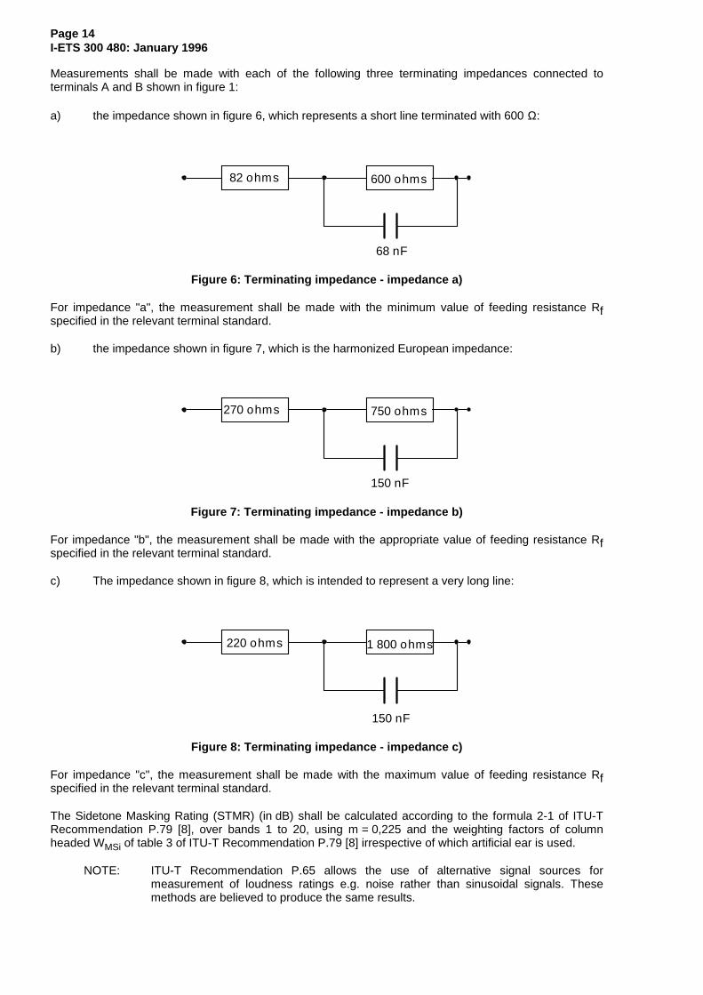
Measurements shall be made with each of the following three terminating impedances connected toterminals A and B shown in figure 1:
a) the impedance shown in figure 6, which represents a short line terminated with 600 Ω:
82 ohms 600 ohms
68 nF
Figure 6: Terminating impedance - impedance a)
For impedance "a", the measurement shall be made with the minimum value of feeding resistance Rfspecified in the relevant terminal standard.
b) the impedance shown in figure 7, which is the harmonized European impedance:
270 ohms 750 ohms
150 nF
Figure 7: Terminating impedance - impedance b)
For impedance "b", the measurement shall be made with the appropriate value of feeding resistance Rfspecified in the relevant terminal standard.
c) The impedance shown in figure 8, which is intended to represent a very long line:
220 ohms 1 800 ohms
150 nF
Figure 8: Terminating impedance - impedance c)
For impedance "c", the measurement shall be made with the maximum value of feeding resistance Rfspecified in the relevant terminal standard.
The Sidetone Masking Rating (STMR) (in dB) shall be calculated according to the formula 2-1 of ITU-TRecommendation P.79 [8], over bands 1 to 20, using m = 0,225 and the weighting factors of columnheaded WMSi of table 3 of ITU-T Recommendation P.79 [8] irrespective of which artificial ear is used.
NOTE: ITU-T Recommendation P.65 allows the use of alternative signal sources formeasurement of loudness ratings e.g. noise rather than sinusoidal signals. Thesemethods are believed to produce the same results.

Page 15I-ETS 300 480: January 1996
4.2.4 Distortion
4.2.4.1 Sending
A 600 Ω resistor shall be connected between terminals A and B shown in figure 1.
A high impedance measuring set, capable of measuring harmonic distortion up to the 5th harmonic ofsignals with fundamental frequencies in the range 315 Hz to 1 000 Hz, shall be connected betweenterminals A and B shown in figure 1.
Pure tones at frequencies of 315 Hz, 500 Hz and 1 000 Hz shall be applied at the MRP. The totalharmonic distortion, dt, shall be determined from the equation:
d 100v v v v
v v v v vt
22
32
42
52
12
22
32
42
52= + + +
+ + + +%
The distortion at any particular harmonic n can be determined from the equation:
d 100v
v v%n
n2
12
n2=
+
where, in each equation vn is the measured r.m.s voltage at harmonic n measured for each frequency andat the maximum and minimum values of feeding resistance, Rf, specified in the relevant terminalstandard.
4.2.4.2 Receiving
A signal generator shall be connected between terminals A and B shown in figure 1.
A measuring set, capable of measuring harmonic distortion up to the 5th harmonic of signals withfundamental frequencies in the range 315 Hz to 1 000 Hz, shall be connected to the artificial ear.
The generator is operated at frequencies of 315 Hz, 500 Hz and 1 000 Hz. The total harmonic distortion,dt, shall be determined from the equation:
d 100p p p p
p p p p pt
22
32
42
52
12
22
32
42
52= + + +
+ + + +%
The distortion at any particular harmonic n can be determined from the equation:
d 100p
p p%n
n2
12
n2=
+
where in each equation, pn is the measured r.m.s sound pressure at harmonic n which is measured foreach frequency and at the maximum and minimum values of feeding resistance, Rf, specified in therelevant terminal standard.
4.2.4.3 Sidetone
A 600 Ω resistor shall be connected between terminals A and B shown in figure 1.
A measuring set, capable of measuring harmonic distortion up to the 5th harmonic of signals withfundamental frequencies in the range 315 Hz to 1 000 Hz, shall be connected to the artificial ear.

Page 16I-ETS 300 480: January 1996
Pure tones at frequencies of 315 Hz, 500 Hz and 1 000 Hz shall be applied at the MRP. The totalharmonic distortion, dt, shall be determined from the equation:
d 100p p p p
p p p p pt
22
32
42
52
12
22
32
42
52= + + +
+ + + +%
where pn is the measured r.m.s sound pressure at harmonic n measured for each frequency and at themaximum and minimum values of feeding resistance, Rf, specified in the relevant terminal standard.
4.2.4.4 Sending power handling capability
A 600 Ω resistor shall be connected between terminals A and B shown in figure 1.
A high impedance measuring set, capable of measuring harmonic distortion, shall be connected toterminals A and B shown in figure 1.
A pure tone at the frequency and level specified in the relevant terminal standard is applied at the MRP.
The total harmonic distortion up to the fifth harmonic shall be measured at the maximum and minimumvalues of feeding resistance Rf specified in the relevant terminal standard.
4.2.4.5 Receiving power handling capability
A signal generator shall be connected between terminals A and B shown in figure 1.
An measuring set, capable of measuring harmonic distortion, shall be connected to the artificial ear.
The signal generator is set to deliver a pure tone at the level and frequency specified in the relevantterminal standard.
The total harmonic distortion up to the fifth harmonic shall be measured at the maximum and minimumvalues of feeding resistance Rf specified in the relevant terminal standard.
4.2.5 Linearity (variation of gain with input level)
4.2.5.1 Sending
The following test shall be used where a simple test of linearity is required.
The test shall be carried out at the value of Rf specified in the relevant terminal standard.
A pure tone signal with a frequency of 1 000 Hz at each of the levels specified in the relevant terminalstandard shall be applied at the MRP.
The sending sensitivity shall be determined as defined in clause 6 of ITU-T Recommendation P.64 [2].
NOTE: Telephones using non-linear and time variant signal processing techniques require amore complex test procedure.
4.2.5.2 Receiving
The following test shall be used where a simple test of linearity is required.
The test shall be carried out at the value of Rf specified in the relevant terminal standard.
A pure tone signal with a frequency of 1 000 Hz at each of the levels specified in the relevant terminalstandard shall be applied at terminals A and B shown in figure 1.
The receiving sensitivity shall be determined as defined in clause 7 of ITU-T Recommendation P.64 [2].

Page 17I-ETS 300 480: January 1996
NOTE: Telephones using non-linear and time variant signal processing techniques will requirea more complex test procedure.
4.2.6 Noise
4.2.6.1 Sending
A 600 Ω resistor shall be connected between terminals A and B shown in figure 1.
A measuring set of high impedance, calibrated in dBm and using psophometric weighting according totable 4 of CCITT Recommendation O.41 [9] shall be connected between terminals A and B shown infigure 1.
The noise level shall be measured by averaging over a minimum period of 1 s. The measurement is madethree times and the lowest value of the three measurements shall be selected as a determination of thenoise level.
Measurements shall be made at the maximum and minimum values of feeding resistance, Rf, specified inthe relevant terminal standard.
NOTE: This test does not test for noise correlated with the signal which may be caused bynon-linear and time variant signal processing techniques.
4.2.6.2 Receiving
A 600 Ω resistor shall be connected between terminals A and B shown in figure 1.
A measuring set calibrated in dBPa and using A-weighting shall be connected to the artificial ear shown infigure 1.
Measurements shall be made at the maximum and minimum values of feeding resistance, Rf, specified inthe relevant terminal standard.
The noise level shall be measured by averaging over a minimum period of 1 s. The measurement is madethree times and the lowest value of the three measurements shall be selected as a determination of thenoise level.
NOTE: This test does not test for noise correlated with the signal which may be caused bynon-linear and time variant signal processing techniques.
4.2.7 Echo Return Loss
A suitable measuring set for measuring impedance shall be connected between terminals A and B shownin figure 1.
The earcap shall be applied to the artificial ear.
Measurements shall be made with the value(s) of Rf specified in the relevant terminal standard.
The test level across terminals A and B shown in figure 1 shall be - 18 dBV ± 3 dB.
The input impedance of the apparatus shall be measured at frequencies spaced not greater thanone-twelfth of an octave apart, within the range 300 Hz to 3 400 Hz inclusive.
NOTE 1: The frequencies do not need to be harmonically related.

Page 18I-ETS 300 480: January 1996
For each value of impedance measured, the Return Loss (RL) (in dB) shall be calculated from theformula:
RL 20logZ Z
Z Z dB10
b t
b t
= +−
where:
Zt is the apparatus impedance, measured;
Zb is the reference impedance shown in figure 7.
For each value of Rf specified, the ERL shall be calculated (in dB), in accordance with ITU-TRecommendation G.122 [10], using the formula:
ERL 3,24 10log A A log f log f dB10 i i 1i 1
n10 i 10 i 1= − +∑ × −−
=−b g b g
where:
Ai is the return loss power ratio at frequency fi expressed as:
Ai = 10-(decibel return loss at fi)/10;
A0 is the ratio at fo = 300 Hz;
An is the ratio at fn = 3 400 Hz.
NOTE 2: The test method specified does not include all of the mechanical and acousticfeedback effects which may occur in normal use. However, these effects usually canbe ignored.
4.2.8 Instability
Measurements shall be made under the following conditions:
a) at the minimum value of the feeding resistance, Rf specified in the relevant terminal standard witha resistance of 600 Ω connected between terminals A and B shown in figure 1;
b) at the maximum value of the feeding resistance, Rf specified in the relevant terminal standard withthe impedance shown in figure 8 connected between terminals A and B shown in figure 1.
The handset shall be positioned on one inside surface that is of three perpendicular plane, smooth, hardsurfaces forming a corner. Each surface shall extend 0,5 m from the apex of the corner. One surface shallbe marked with a diagonal line extending from the corner formed by the three surfaces, as shown infigure 9.
The handset, with the transmission circuit fully active, shall be positioned on the defined surface asfollows:
1) the mouthpiece and earcap shall face towards the surface;
2) the handset shall be placed centrally along the diagonal line with the earcap nearer to theapex of the corner;
3) the extremity of the handset shall coincide with the normal to the reference point, as shown infigure 9.
If necessary, the position of the handset should be adjusted to achieve the "just off-hook" position.

Page 19I-ETS 300 480: January 1996
Checks shall be made to establish that the signal level resulting from any sustained audio frequencyoscillation (up to 10 kHz) measured between terminals A and B as shown in figure 1 is less than 10 mV.
Referencepoint250
500
500 500
250Corner Reference point
All dimensions are in millimeters
Figure 9: Handset position for instability test
Where the mouthpiece of the handset is separate from the earpiece:
- the telephone shall be mounted in free air with the mouthpiece in a normal position;
- the earcap is pointed directly at the mouthpiece with a distance of 150 mm between the front planesof each.
If necessary, the telephone should be placed in the off-hook position.
Checks shall be made to establish that the signal level resulting from any sustained audio frequencyoscillation (up to 10 kHz) measured between terminals A and B shown in figure 1 is less than 10 mV.
Page 20I-ETS 300 480: January 1996
Annex A (normative): Maximum signal sent to line
A.1 Maximum signal sent to line
Where the relevant access requirement contains no test for the maximum signal to line when driven by anacoustic input, the following test shall be used:
A measuring set capable of measurement in the frequency range 200 Hz to 10 kHz, with a non-reactiveimpedance of 600 Ω and calibrated in dBV, shall be connected between terminals A and B shown infigure 1.
A sinusoidal signal at a frequency of 1 000 Hz and a sound pressure level of 20 dBPa shall be applied tothe MRP.
The output voltage shall be measured at the values of feeding resistance, Rf, specified in the relevantterminal standard.
NOTE: When this test is used, limits appropriate to speech signals shall be used (e.g. 8Vpeak-to-peak).

Page 21I-ETS 300 480: January 1996
Annex B (informative): Acoustic shock
B.1 Continuous signal
A frequency generator with a non-reactive source impedance of 600 Ω is connected between terminals Aand B shown in figure 1.
Measurements are made at the values of feeding resistance, Rf, specified in the relevant terminalstandard.
The frequency generator is set to deliver pure tone signals at an e.m.f. of 24 dBV r.m.s at 1/3 octaveintervals at the preferred frequencies given by the R10 series of preferred numbers in ISO 3 [7] forfrequencies from 200 Hz to 10 kHz.
For each band the sound pressure in the artificial ear is measured.

Page 22I-ETS 300 480: January 1996
Annex C (informative): Immunity to out-of-band signalling
C.1 Sending
The following test should be used where a test is required to evaluate the effect on speech performance ofout-of-band signalling such as meter pulses.
Two measurements should be made:
a) one reference measurement without out-of-band signalling;b) a second measurement with out-of-band signalling.
The difference in dB between the two measurement results represents the disturbing effect of theout-of-band signalling on the speech performance.
The measurements should be made at the maximum value of feeding resistance Rf specified in therelevant terminal standard with the terminating impedance of figure 7 (subclause 4.2.3) connectedbetween terminals A and B shown in figure 1 (subclause 4.1.10).
A pure tone signal with a frequency of 1 000 Hz at the level specified in the relevant terminal standardshould be applied at the MRP.
The level of the output signal appearing across terminals A and B shown in figure 1 (subclause 4.1.10)should be measured selectively.
A signal representative of the out-of-band signalling (in terms of level, frequency and period) should beapplied in series with the terminating impedance by a generator of negligible source impedance.
The level of the output signal should be measured again and the disturbing effect determined byaveraging the result over the period of application of the out-of-band test signal.
NOTE 1: This test does not test for:
- the degradation due to total harmonic distortion in the voice band;- the performances of non-linear and time variant signal processing techniques;- the effect of more complex out-of-band signals.
NOTE 2: For the purpose of these tests, the insertion loss and return loss of the feeding circuitshould meet the same limits up to 20 kHz as are otherwise applied at 10 kHz.
C.2 Receiving
The following test should be used where a test is required to evaluate the effect on speech performance ofout-of-band signalling such as meter pulses.
Two measurements should be made:
a) one reference measurement without out-of-band signalling;b) a second measurement with out-of-band signalling.
The difference in dB between the two measurement results represents the disturbing effect of theout-of-band signalling on the speech performance.
The measurements should be made at the maximum value of feeding resistance Rf specified in therelevant terminal standard with the terminating impedance of figure 7 (subclause 4.2.3) connectedbetween terminals A and B shown in figure 1 (subclause 4.1.10).
A pure tone signal with a frequency of 1 000 Hz at the level specified in the relevant terminal standardshould be applied in series with the terminating impedance by a generator of negligible source impedance.
The level of the output signal appearing at the receiver should be measured selectively.

Page 23I-ETS 300 480: January 1996
A signal representative of the out-of-band signalling (in terms of level, frequency and period) also shouldbe applied in series with the terminating impedance by a generator of negligible source impedance.
The level of the output signal should be measured again and the disturbing effect determined byaveraging the result over the period of application of the out-of-band test signal.
NOTE 1: This test does not test for:
- the degradation due to total harmonic distortion in the voice band;- the performances of non-linear and time variant signal processing techniques;- the effect of more complex out-of-band signals.
NOTE 2: For the purpose of these tests, the insertion loss and return loss of the feeding circuitshould meet the same limits up to 20 kHz as are otherwise applied at 10 kHz.

Page 24I-ETS 300 480: January 1996
Annex D (informative): Bibliography
For the purposes of this I-ETS, the following documents have been referenced informatively:
- ITU-T Recommendation P.10 (1993): "Vocabulary of terms on telephone transmission quality andtelephone sets".
- ITU-T Recommendation P.65 (1993): "Objective instrumentation for the determination of loudnessratings".
- CCITT Recommendation P.35 (1988): "Handset telephones".
- I-ETS 300 677: "Public Switched Telephone Network (PSTN); Requirements for handsettelephony".

Page 25I-ETS 300 480: January 1996
History
Document history
February 1995 Public Enquiry PE 79: 1995-02-20 to 1995-06-16
November 1995 Vote V 91: 1995-11-06 to 1995-12-29
January 1996 First Edition
ISBN 2-7437-0492-6Dépôt légal : Janvier 1996