Embed Size (px)
Citation preview

Interfacing Devices
Chapter 2

Objectives• Identify the schematic diagrams, describe the
operations, and calculate the outputs of the comparator, inverting, summing, noninverting, and difference operational amplifiers (op amps)
• Identify the schematic diagrams of the integrator and differentiator op amps and draw the output waveforms they produce when various input signals are applied

Objectives (cont’d.)• Given applied input signals, indicate the
resulting output of the digital comparator device
• Describe the wave-shaping capability and operating characteristics of a Schmitt trigger
• Determine how optoelectronic devices are switched and explain the isolation function they perform

Objectives (cont’d.)• Explain the operation of analog-to-digital and
digital-to-analog converters, determine their resolution, and make the proper wiring connections to their integrated circuit packages
• Assemble monostable and astable multivibrators using a 555 monolithic integrated circuit and use calculations to determine their output

Fundamental Operational Amplifiers
• Op amps– uA741: one of the most popular
• Operational amplifier comparator
• Inverting operational amplifier– Control gain using feedback
Fundamental Operational Amplifiers
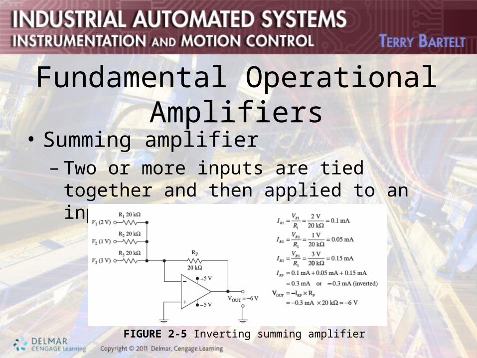
• Summing amplifier– Two or more inputs are tied together and then
applied to an input lead of an op amp
FIGURE 2-5 Inverting summing amplifier

Fundamental Operational Amplifiers
• Noninverting amplifier– Equation used to determine the gain:
– Output voltage:
• Difference operational amplifier– Finds the algebraic difference between two input
voltages

Signal Processors
• Devices that change or modify signals applied to inputs
• Integrator operational amplifier– Continuously increases its gain over a period
of time
• Differentiator operational amplifier– Produces an output proportional to the rate of
change of the input signal

Signal Processors (cont’d.)
• Wave-shaping Schmitt trigger– Device that produces rectangular wave signals– Operation: three time periods
FIGURE 2-10b Schmitt trigger

Comparator Devices
• Function: produce an output error signal that is determined by the difference between the two inputs
• Magnitude comparator – Compare two binary numbers– 4-bit magnitude comparator
• Connect several to compare larger numbers

Optoelectronic Interface Devices
• Pass electrical signals from one element to another by means of light energy and semiconductors– Light source: usually a semiconductor light
emitting diode (LED)
• Photodiode– PN-junction device that operates in the
reverse-bias mode

Optoelectronic Interface Devices (cont’d.)
• Phototransistor – Depends on a light source for its operation
• Photo SCR – Light-activated SCR, or LASCR– Usually activated by light rather than a gate
voltage that draws gate current

Optoelectronic Interface Devices (cont’d.)
• Photo triac – Bidirectional device designed to switch AC
signals and pass current in both directions
• Optocoupler– Package does not allow light to enter
• Optoisolator– No electrical connection between the emitter
and the detector

Digital-to-Analog Converters
• Convert digital signals representing binary numbers into proportional analog voltages
• Resolution– Number of equal divisions into which a DAC
divides the reference voltage
• Integrated-circuit digital-to-analog converter– Example: 8-bit DAC0808

Analog-to-Digital Converters
• Converts analog input voltages into proportional digital number
• Successive-approximation register (SAR)– Circuit used to operate at high speeds
• Integrated-circuit analog-to-digital converter– Example: ADC0804

Timing Devices
• Produce rectangular signals referred to as square-wave signals
• Monostable multivibrators– Produce single pulse signals– Example: 555 monostable multivibrator
• Astable multivibrators– Produce continuous pulse signals– Example: 555 astable multivibrator