Embed Size (px)
Citation preview

i
Interface 1010
Potentiostat/Galvanostat/ZRA
Operator’s Manual
Copyright 2014–2018 Gamry Instruments, Inc.
Revision 1.2
January 10, 2018
988-00063

ii
If You Have Problems
Please visit our service and support page at www.gamry.com/service-support/. This page contains
information on installation, software updates, and training. It also contains links to the latest available
documentation. If you are unable to locate the information you need from our website, you can contact us
via e-mail using the link provided on our website. Alternatively, you can contact us one of the following
ways:
Internet www.gamry.com/service-support/
Telephone (215) 682-9330 9:00 AM−5:00 PM US Eastern Standard Time
(877) 367-4267 Toll-free US & Canada Only
Please have your instrument model and serial numbers available, as well as any applicable software and
firmware revisions.
If you have problems in installation or use of a system containing an Interface 1010, call from a phone next
to your computer, where you can type and read the screen while talking to us.
We are happy to provide a reasonable level of free support for registered users of the Interface 1010
Potentiostat/Galvanostat/ZRA. Reasonable support includes telephone assistance covering the normal
installation, use, and simple customization of a computerized system containing an Interface 1010
connected to a Windows®-compatible computer.
A service contract that extends both the hardware warranty and software update period is available at an
additional charge. Software updates do not include software enhancements offered to our customers at
additional cost.
Enhancements to the Interface 1010 and Gamry’s standard applications software that require significant
engineering time on our part can be performed on a contract basis. Contact us with your requirements.

iii
Limited Warranty
Gamry Instruments, Inc. warrants to the original user of this product that it shall be free of defects resulting
from faulty manufacture of the product or its components for a period of two years from the original
shipment date of your purchase.
Gamry Instruments, Inc. makes no warranties regarding either the satisfactory performance of the Interface
1010 Potentiostat/Galvanostat/ZRA including the software provided with this product or the fitness of the
product for any particular purpose. The remedy for breach of this Limited Warranty shall be limited solely
to repair or replacement, as determined by Gamry Instruments, Inc., and shall not include other damages.
Gamry Instruments, Inc. reserves the right to make revisions to the system at any time without incurring any
obligation to install same on systems previously purchased. All system specifications are subject to change
without notice.
There are no warranties which extend beyond the description herein. This warranty is in lieu of, and
excludes any and all other warranties or representations, expressed, implied or statutory, including
merchantability and fitness, as well as any and all other obligations or liabilities of Gamry
Instruments, Inc.; including but not limited to, special or consequential damages.
This Limited Warranty gives you specific legal rights and you may have others, which vary from state to
state. Some states do not allow for the exclusion of incidental or consequential damages.
No person, firm or corporation is authorized to assume for Gamry Instruments, Inc., any additional
obligation or liability not expressly provided herein except in writing duly executed by an officer of Gamry
Instruments, Inc.

iv
Disclaimers
Gamry Instruments, Inc. cannot guarantee that the Interface 1010 Potentiostat/Galvanostat/ZRA will work
with all computer systems, operating systems, and third-party software applications/hardware/software.
The information in this manual has been carefully checked and is believed to be accurate as of the time of
printing. However, Gamry Instruments, Inc. assumes no responsibility for errors that might appear.
Copyrights
Interface 1010 Potentiostat/Galvanostat/ZRA Operator’s Manual copyright 2014−2018 Gamry
Instruments, Inc., all rights reserved. Gamry Framework copyright 1989−2018 Gamry Instruments, Inc.,
all rights reserved.
Interface 1010™, Reference 3000™, Reference 600™, ECM8™, Gamry Framework™, VistaShield™ and
Gamry™ are trademarks of Gamry Instruments, Inc.
Windows is a registered trademark of Microsoft Corporation.
No part of this document may be copied or reproduced in any form without the prior written consent of
Gamry Instruments, Inc.

Table of Contents
Chapter 1: Safety Considerations .................................................................................................. 1-1 Inspection ......................................................................................................................... 1-1 Product Safety .................................................................................................................. 1-1 AC Mains Connection to the Power Brick .......................................................................... 1-1 Grounding in the Interface 1010 ....................................................................................... 1-2 Operation with Earth-grounded Cells and Auxiliary Apparatus ........................................... 1-3 Temperature and Ventilation ............................................................................................. 1-3 Defects and Abnormal Stresses .......................................................................................... 1-4 Environmental Limits......................................................................................................... 1-4 Cleaning ........................................................................................................................... 1-4 Service ............................................................................................................................. 1-5 RF Warning ...................................................................................................................... 1-5 Electrical Transient Sensitivity ............................................................................................ 1-5 CE Compliance ................................................................................................................. 1-6 RoHS Compliance ............................................................................................................ 1-6
Chapter 2: Introduction ................................................................................................................ 2-1 About this Manual ............................................................................................................ 2-1 About the Interface 1010 .................................................................................................. 2-1 Software and Applications ................................................................................................. 2-2 Multichannel Systems ....................................................................................................... 2-2 Front Panel Customization ................................................................................................ 2-3 Notational Conventions..................................................................................................... 2-3
Chapter 3: Installation ................................................................................................................... 3-1 Initial Visual Inspection ..................................................................................................... 3-1 Physical Location .............................................................................................................. 3-1 Computer Requirements ................................................................................................... 3-2 Quick-start Guide for System Installation ........................................................................... 3-2 Software Installation .......................................................................................................... 3-2 Reboot your Computer after Software Installation .............................................................. 3-3 Power Cord and Power Connection .................................................................................. 3-3 Power Up Test .................................................................................................................. 3-4 USB Cables ....................................................................................................................... 3-5 Multiple Potentiostat Systems ............................................................................................ 3-5 Cell Cable Installation ....................................................................................................... 3-6 Front Panel USB LED ........................................................................................................ 3-6 Running the Framework .................................................................................................... 3-7 Framework Device Status Bar ............................................................................................ 3-7 Types of Interface 1010 instruments .................................................................................. 3-8 Authorization Codes and Label ......................................................................................... 3-8 Firmware Update .............................................................................................................. 3-9 The Interface 1010 Customization Label ........................................................................... 3-9
Chapter 4: Calibration .................................................................................................................. 4-1 Introduction ...................................................................................................................... 4-1 DC Calibration .................................................................................................................. 4-1 Cable Calibration .............................................................................................................. 4-3
Chapter 5: Cell Connections ......................................................................................................... 5-1 Normal Cell Connections .................................................................................................. 5-1 ZRA-Mode Cell Connections ............................................................................................. 5-2 Membrane Cell Connections ............................................................................................. 5-3

Chapter 6: Panel Indicators and Connectors .................................................................................. 6-1 Front Panel ....................................................................................................................... 6-1 Rear Panel ........................................................................................................................ 6-5
Chapter 7: Instrument Circuitry ..................................................................................................... 7-1 Interface 1010 Schematic/Block Diagrams ......................................................................... 7-1
Chapter 8: Stability in Potentiostat Mode ....................................................................................... 8-1 Capacitive Cells and Stability ............................................................................................. 8-1 Improving Potentiostat Stability ......................................................................................... 8-2
Chapter 9: Measurement of Small Signals ...................................................................................... 9-1 Overview .......................................................................................................................... 9-1 Measurement System Model and Physical Limitations ........................................................ 9-1 Hints for System and Cell Design ....................................................................................... 9-5 Floating Operation ............................................................................................................ 9-7
Appendix A: Interface 1010 Specifications ...................................................................................... 9-1 Appendix B: Interface 1010 Cell Connector .................................................................................... 9-1 Appendix C: I/O Connectors .......................................................................................................... 9-1
User I/O Connector ........................................................................................................... 9-1 Sync Port .......................................................................................................................... 9-2 Monitor Connector ........................................................................................................... 9-3
Appendix D: Power LED Blink Codes ............................................................................................. 9-1 Normal Start-up ................................................................................................................ 9-1 Failure in an electronics module ........................................................................................ 9-1 Severe problem................................................................................................................. 9-1 Error Messages and Limitations .......................................................................................... 9-1
Appendix E: CE Certificate ............................................................................................................. 9-1 Appendix F: Heat in Interface 1010 Multichannel Systems .............................................................. 9-1
Introduction to Device Power-Dissipation.......................................................................... 9-1 Potentiostat/Galvanostat Power Model............................................................................... 9-2 Discharging a Battery ........................................................................................................ 9-2 Single Interface 1010 ........................................................................................................ 9-3 Vertical Stacks ................................................................................................................... 9-3 Interface Power Hub Systems ............................................................................................ 9-3
Appendix G: Capabilities of Various Models of Interface 1010 ........................................................ 9-1 Appendix H: Index ........................................................................................................................ 9-1

Chapter 1: Safety Considerations--Inspection
1 - 1
Chapter 1: Safety Considerations
Your Interface 1010 Potentiostat/Galvanostat/ZRA has been supplied in a safe condition. This chapter
contains information and warnings that you must follow to insure continued safe operation of the Interface
1010.
Inspection
When you receive your Interface 1010 Potentiostat/Galvanostat/ZRA, inspect it for evidence of shipping
damage. If you note any damage, please notify Gamry Instruments Inc. and the shipping carrier
immediately. Save the shipping container for possible inspection by the carrier.
Product Safety
The Interface 1010 has been designed, tested and certified to meet the requirements of EN 61010, Safety
requirements for electrical equipment for measurement, control, and laboratory use. As defined in this
standard, it is a Category II apparatus, with any “hazardous live voltages” protected by “reinforced
insulation.”
Most of the Interface 1010 circuitry is at voltages low enough to be considered safe. The Interface 1010
contains a limited amount of internal circuitry that is at “hazardous live” voltages as defined in EN 61010
(the standard mentioned above). “Reinforced insulation” (again defined in EN 61010) is used to reduce the
risk of electrical shock caused by this hazardous live voltage.
The majority of the Interface 1010’s circuitry does not contain voltages higher than 24 V DC. As a
generalization, input and output voltages in the Interface 1010 are limited to 24 V. This voltage level is
considered safe.
The “AC Adapter” supplied with the Interface 1010 is certified under EN 60950. The AC Adapter converts
the AC mains voltage to 48 V DC, which is used to power the Interface 1010.
Always use the AC adapter (power brick) supplied with your Interface 1010 to supply DC power to the
instrument.
AC Mains Connection to the Power Brick
The Interface 1010 does not connect directly to an AC Mains supply. Instead, the mains are connected to
desktop AC adapter (power brick), which outputs 48 V DC, which in turn powers the Interface 1010.
Caution: Use only Gamry-approved DC power sources with your Interface 1010. Other
power sources may alter the performance and/or safety characteristics of the Interface 1010.
Warning: An Interface 1010 damaged in shipment can be a safety hazard. Do not operate
damaged apparatus until a qualified service technician has verified its safety. Tag a damaged Interface 1010
to indicate that it could be a safety hazard.

Chapter 1: Safety Considerations--Grounding in the Interface 1010
1 - 2
The Interface 1010 is normally provided with an AC line cord suitable for your location. This AC line cord
connects the AC mains to the AC power adapter. If your Interface 1010 has been provided without an AC
line cord, or a cord that is not compatible with your local AC mains socket, obtain a line cord certified for
use in your country. Contact your local Gamry Representative or e-mail to [email protected] if you
are uncertain what AC line cord to use.
Grounding in the Interface 1010
The circuitry and the metal case of the Interface 1010 are not connected to an earth ground. If they were
connected to earth ground, it would compromise the Interface 1010’s ability to make measurements in
electrochemical cells that contain earth-grounded metal. A few examples of such cells include autoclaves,
metallographic stress apparatus, and detectors for capillary electrophoresis.
Most electrochemical cells are isolated from earth ground, so isolation of the Interface 1010 from earth is
not required. In these cases, connection of the Interface 1010 chassis to an earth ground may lower the
noise seen in an electrochemical test. A Chassis Ground banana jack on the rear panel of the Interface
1010 easily implements this connection. Simply run a wire from this binding post to a suitable source of
earth ground. A black 1.2-meter wire is provided with the Interface 1010 to facilitate this connection.
This connection of the Interface 1010 to an earth ground is not a “Protective Earth Ground” as defined in
EN 61010. The Interface 1010 is safe in the absence of this connection.
This binding post is not intended for any use other than connecting the Interface 1010 to an earth ground
to improve shielding against noise. Connecting this binding post to a hazardous voltage can create a
significant safety hazard.
Sources of earth ground include
• Most metal water pipes,
• The chassis of most electronic apparatus (which are generally earth-grounded), and
• The protective ground terminal of an AC mains power plug.
We recommend that you discuss grounding with an electrical or electronics professional prior to making this
earth-ground connection.
The Interface 1010’s AC Adapter is rated for operation from 100 to 240 V AC, 47 to 63 Hz.
It should therefore be useful throughout the world.
Warning: Do not connect the chassis ground binding post to any voltage other than earth
ground. An improper connection can create a safety hazard, which could result in personal injury or death.

Chapter 1: Safety Considerations--Operation with Earth-grounded Cells and Auxiliary Apparatus
1 - 3
The Interface 1010 contains surge suppressors that limit the voltage difference between the Interface
1010’s chassis ground and earth ground to about 28 V. These surge suppressors are not part of the safety
mechanisms in the Interface 1010. Instead they are present to limit the possibility of improper instrument
operation or instrument damage caused by electrostatic discharge (static electricity) and other surge events
such as lightning.
Operation with Earth-grounded Cells and Auxiliary Apparatus
As described above, the Interface 1010 circuitry is isolated from earth ground, allowing it to make
measurements on cells that include an earth ground. This ground isolation is often called floating operation.
Cells with earth ground include many autoclaves, pipelines and storage tanks, and many fuel cell systems.
Connection of the Interface 1010 to auxiliary apparatus will often earth-ground the Interface 1010,
destroying its ability to float and make measurements on earth-grounded cells. Connection of the Monitor
Connector to an oscilloscope is an example where the instrument is earthed.
The User I/O connector can be connected to earth-grounded apparatus without earth-grounding the
Interface 1010, if the cabling is done carefully. The metal shell on the Interface 1010 User I/O Connector is
connected to the instrument’s chassis, which is a floating ground. In a system that needs isolation from
earth ground, the shield of a User I/O cable must not connect the D-connector’s metal shell to earth
ground. Reference all User I/O signals to pin 6 of the D-connector, which is an earth ground on the
Interface 1010.
Temperature and Ventilation
Your Interface 1010 Potentiostat/Galvanostat/ZRA was designed for indoor use at ambient temperatures
between 0C and 45C.
The Interface 1010 uses forced air-cooling to keep the Interface 1010 components within their operating
temperature range. Most of the air needed to cool the Interface 1010 enters the chassis through holes in its
bottom plate. Some air also enters the chassis from small slots on the right side of the chassis (as viewed
from the front of the instrument).
The fan within the Interface 1010 has two operating speeds with different audible noise levels. The
Interface 1010 normally operates with the lower speed, quieter fan setting. The fan switches to a higher
speed when the Interface 1010’s internal heat-sink gets hotter than 50C.
The cooling air flows through a heat sink mounted inside the chassis. The air exits through a large array of
slots on the left side of the instrument.
Caution: Floating operation of the Interface 1010 can be compromised by improper
cables to your I/O Connector. We do not recommend use of standard 15-pin shielded cables with this
connector. Custom cables with the shield connected to pin 6 of the D-connector are preferred.

Chapter 1: Safety Considerations--Defects and Abnormal Stresses
1 - 4
Be careful when operating the Interface 1010 in an enclosed space (such as an enclosed relay rack or
NEMA enclosure). The temperature within the enclosure must not exceed 45C. You may need to provide
ventilation holes or even forced air-cooling for the enclosed space if excessive temperature rise occurs.
Defects and Abnormal Stresses
Treat your Interface 1010 as potentially hazardous if any of the following is true of the unit:
• It shows visible damage,
• It does not operate properly,
• It has been stored for a long period of time under unfavorable conditions,
• It has been dropped or subjected to severe transport stress,
• It has been subjected to environmental stress (corrosive atmosphere, fire, etc.).
Do not use your Interface 1010 or any other apparatus if you think it could be hazardous. Have it checked
by qualified service personnel.
Environmental Limits
There are environmental limit conditions on the storage, shipping, and operation of this equipment. The
Interface 1010 is not designed for outdoor use.
Storage Ambient temperature –40C to 75C
Relative humidity Maximum 90% non-condensing
Shipping Same as storage plus
Acceleration Maximum 30 G
Operation Ambient temperature 0C to 45C
Relative humidity Maximum 90% non-condensing
Cleaning
Disconnect the Interface 1010 from all power sources prior to cleaning.
Use a cloth lightly dampened with either clean water or water containing a mild detergent to clean the
outside of the Interface 1010 enclosure. Alternatively, you can use isopropyl alcohol. Do not use a wet rag
or allow fluid to enter the Interface 1010 enclosure. Do not immerse the Interface 1010 in any type of
cleaning fluid (including water). Do not use any abrasive cleaners.
Caution: Do not block the airflow into or out of the Interface 1010 chassis. The circuitry
is thermally protected so over-temperature will cause the instrument to enter a shut-down state. If shut-
down occurs during data-acquisition, experimental data could be lost. Running the Interface 1010
without adequate cooling could also shorten the time to failure of some of the circuitry.
Warning: The Interface 1010 is not designed for operation in conditions where liquid
water may enter the chassis, or water vapor may condense within the chassis. Operation of an Interface
1010 that has water within the chassis can create a safety hazard, which could result in personal injury
or death.

Chapter 1: Safety Considerations--Service
1 - 5
Service
Your Interface 1010 Potentiostat/Galvanostat/ZRA has no user-serviceable parts inside. Refer all service to a
qualified service technician.
RF Warning
The Interface 1010 has been tested for both radiated and conducted RF interference and for immunity to
RF fields, and has been found to be in compliance with FCC Part 18 and EN 61326:1998—Electrical
equipment for measurement, control, and laboratory use— EMC Requirements.
However, your Interface 1010 Potentiostat/Galvanostat/ZRA does still generate some radio-frequency
energy. The radiated levels are low enough that the Interface 1010 should not create an interference
problem in most industrial laboratory environments.
Your Interface 1010 Potentiostat/Galvanostat/ZRA can also respond to environmental radio-frequency
energy. We recommend you avoid using cell-phone and other radio-frequency equipment in the same
room as an Interface 1010. The Interface 1010 circuitry has been tested for operation in high-intensity RF
fields, and has demonstrated little response to those fields. However, there is no guarantee that the
electrochemical cell and its connections will not respond to RF fields. This response will most often appear
as DC shifts in a cell’s response caused by rectification of the RF signal.
A Faraday cage surrounding your cell can be used to minimize the effect of environmental RF fields. If your
cell is isolated from earth ground, Gamry recommends connecting your Interface 1010 to earth ground and
then connecting the Faraday cage to the Interface 1010’s floating ground (the black lead on the cell cable).
Electrical Transient Sensitivity
Your Interface 1010 Potentiostat/Galvanostat/ZRA was designed to offer reasonable immunity from
electrical transients, including transients on the incoming AC Mains supply and Electrostatic Discharge. It
has been tested for compliance with EN 61326:1998—Electrical equipment for measurement, control, and
laboratory use—EMC Requirements describing acceptable limits for electrical transient susceptibility in
laboratory test equipment. It should continue to operate when subject to the standard ESD and power-line
events defined in EN61326.
In severe cases involving transients beyond the limits tested in EN61326, the Interface 1010 could still
malfunction as a result of electrical transients. If you are having problems in this regard, the following steps
may help:
If the problem is static electricity (sparks are apparent when you touch the Interface 1010 or its cables):
• Try placing your Interface 1010 on a static-control work surface. Static-control work surfaces are
now generally available from computer-supply houses and electronics-tool suppliers. An antistatic
floor mat may also help, particularly if a carpet is involved in generating the static electricity.
• Air-ionizers or even simple air-humidifiers can reduce the voltage available in static discharges.
If the problem is AC power-line transients (often from large electrical motors near the Interface 1010):
Warning: Never operate the Interface 1010 with any cover or panel on the chassis
open. Dangerous voltages may be present at several points within the Interface 1010 chassis, including
PC board traces. Always remove the power connection before opening the Interface 1010 case.

Chapter 1: Safety Considerations--CE Compliance
1 - 6
• Try plugging your Interface 1010 into a different AC power branch circuit.
• Plug your Reference into a power-line surge suppressor. Inexpensive surge suppressors are now
generally available because of their use with computer equipment.
Contact Gamry Instruments, Inc. if these measures do not solve the problem.
CE Compliance
The European Community has instituted standards limiting radio-frequency interference emitted by
electronic devices, setting limits for susceptibility of apparatus to RF energy and transient events, and
mandating safety requirements. Gamry Instruments, Inc. has designed and tested the Interface 1010 to
comply with these standards.
The relevant CE regulations include EN 61010 and EN 61326.
RoHS Compliance
The Interface 1010 has been built using lead-free components and lead-free solder. It is in compliance with
the European RoHS initiative.

Chapter 2: Introduction--About this Manual
2 - 1
Chapter 2: Introduction
About this Manual
This manual covers the installation, safety, and use of the Gamry Instruments Interface 1010
Potentiostat/Galvanostat/ZRA.
This manual describes use of an Interface 1010 with Revision 7 (and later revisions) of the Gamry
Framework software. It is equally useful when setting up a newly purchased potentiostat or modifying the
setup of an older potentiostat for use with new software.
Chapter 1 was an in-depth discussion of safety issues. This chapter describes this manual and gives a brief
overview of the Interface 1010 features. Chapter 3 contains Interface 1010 installation instructions. Chapter
4 describes cell cable connections and Chapter 5 describes the Interface 1010’s front and rear panels.
Chapter 6 is a description of the electronics circuitry in the Interface 1010. Chapter 7 covers the difficult
issues of potentiostat stability and approaches to prevent oscillation. Chapter 8 discusses the realities of
low-current, high-impedance measurements.
You will find dry technical material such as specifications and connector pin-outs in the Appendices.
Appendix E discusses heat generation in multiple potentiostat systems based on the Interface 1010, and
makes recommendations for heat management.
This manual discusses software installation or software operation in some detail. The installation is written
assuming installation using Revision 7 of Gamry’s Framework™ software. Installation is also described in
Gamry’s Quick-Start Installation Guide for USB Potentiostats.
Software support for the Interface 1010 is described in the Gamry Help system.
All Gamry Instruments applications running under the Gamry Framework control the Interface 1010 via a
PSTAT object. See the Framework’s Help for information concerning PSTAT objects and their functions.
About the Interface 1010
The Interface 1010 is a value-oriented, research-grade electrochemical instrument packaged in a small,
easy-to-handle case. It works particularly well in systems with multiple instruments connected to one
computer. It offers measurement capabilities similar or superior to those of instruments that are more than
ten times its size and weight and more than three times its price.
The Interface 1010 can operate as a potentiostat, a galvanostat, or a ZRA (zero-resistance ammeter).
Interface 1010 features include:
• Nine-decade current auto-ranging,
• Electrical isolation from earth ground,
• Current-interrupt iR-compensation, and
• Both analog and digital filtering.
A sine-wave generator on the Interface 1010 allows its use for accurate impedance measurements at
frequencies up to 2 MHz. EIS performance is excellent for both high-impedance and low-impedance
systems.
Data can be acquired at frequencies up to 100 000 points per second.
A unique DSP (Digital Signal Processing) data-acquisition mode allows the Interface 1010 to reject noise,
from the instrument itself, from the electrochemical cell, and from the lab environment. In many cases
where other instruments require a cell in a Faraday shield to make quiet measurements, the Interface 1010
can be used with the cell exposed on a bench top.

Chapter 2: Introduction--Software and Applications
2 - 2
The Interface 1010, like all Gamry potentiostats, requires a computer for its use. Unlike our older
potentiostats, the Interface 1010 interfaces to the computer through a USB connection. The USB
connection has become truly universal, with USB ports found on all modern computers. Gamry Windows®-
based software currently supports up to 16 Gamry potentiostats connected to one computer. A system can
include a mixture of Gamry Reference and Interface Family instruments.
The Interface 1010 is isolated from earth ground. It can therefore be used to make measurements on cells
that contain an earth-grounded metal. A few of the many examples of such systems are autoclaves, large
metal storage tanks, stress apparatus, and capillary electrophoresis detectors.
Software and Applications
The Interface 1010 supports all Gamry electrochemical applications software, including Gamry
Electrochemical Energy Software.
The Interface 1010 should be particularly useful in laboratories where high test throughput is required.
Multiple Interface 1010s can be used to configure flexible multichannel systems, where the number of
potentiostats in each system can vary as needed. For example, a dozen Interface 1010s in a laboratory can
be used as one eight-potentiostat system and four stand-alone systems one week, then used as two six-
potentiostat systems the next week.
Typical applications for the Interface 1010 include:
• Corrosion testing,
• Evaluation of protective coatings and paints,
• Research in electrochemical storage and conversion,
• Battery and electrochemical capacitor evaluation,
• Bio-electrochemical testing,
• Electrochemical sensor development.
Multichannel Systems
The Interface 1010 can form several different types of multichannel multiple potentiostat systems.
In one type of system, multiple Interface 1010 units are simply stacked on top of each other. The Interface
1010 chassis was designed for easy and secure stacking. The rubber feet on the bottom of one instrument
mate with indentations in the top of the instrument below.
In this type of system, each Interface 1010 is powered by an individual AC Adapter, which in turn can be
powered by a multiple output AC power strip. The multiple USB connections for the system can be
obtained from an inexpensive commercial USB hub.
In a more formal, less-cluttered system, multiple Interface 1010 units can be added to a special Gamry-
supplied rack called the Interface Power Hub. This smart rack arranges the units side-by-side and takes care
of power and USB connections. Individual units can still be easily added and removed as required.
In some multiple potentiostat systems, users want synchronized operation of several potentiostats. This is
often desirable when multiple units are connected to one electrochemical cell. Examples of this include
ring-disk systems, series-connected laminar-flow generation-detection systems, localized EIS and
electrochemical microscopy.
A special synchronization port (Sync port) on the rear of each Interface 1010 allows one master instrument
to control the clocks and data-acquisition timing of multiple serf instruments. The master can even generate
sine waves used for EIS experiments, and the serfs can acquire very accurate EIS data derived from the
master’s excitation waveform. Additional information concerning synchronization cables can be found in
Appendix C.

Chapter 2: Introduction--Front Panel Customization
2 - 3
Heat can be an issue in a multichannel System. This subject is discussed in detail in Appendix E of this
manual.
Front Panel Customization
The Interface 1010 supports a flexible labeling scheme for identifying potentiostats in a multiple
potentiostat (multichannel) system. A clear window in the plastic overlay on the Interface 1010’s front panel
lets you create your own identification of each potentiostat in a system.
Every Interface 1010 is shipped with its serial number in this label location. More user-friendly labels can
also be displayed, such as Pstat1, Pstat2, Pstat3. Whimsical names such as “Rusty Dog” can also be
displayed in this area. See Chapter 4 for more details.
Notational Conventions
In order to make this manual more readable we have adopted some notational conventions used
throughout this manual:
• Numbered lists. A numbered list is reserved for step-by-step procedures, with the steps always
performed sequentially.
• Bulleted list. The items in a bulleted list, such as this one, are grouped together because they
represent similar items. The order of items in the list is not critical.
• File names and folders. Inside paragraphs, references to computer files and Windows folders are
capitalized, for example: C:\MYGAMRYDATA\CV.DTA and GAMRY.INI.
The term Interface 1010 is generally written in place of the more correct but awkward term Interface 1010
Potentiostat/Galvanostat/ZRA.

Chapter 2: Introduction--Notational Conventions
2 - 4

Chapter 3: Installation--Initial Visual Inspection
3 - 1
Chapter 3: Installation
This chapter of the Gamry Instruments Inc. Interface 1010 Operator’s Manual covers normal installation of the
Interface 1010. We assume the Interface 1010 is installed as part of a Gamry Framework-based
electrochemical measurement system containing a Microsoft Windows®-compatible computer.
Figure 3 - 1
Front View of an Interface 1010
Initial Visual Inspection
After you remove your Interface 1010 from its shipping carton, check it for any signs of shipping damage. If
you note any damage, please notify Gamry Instruments, Inc. and the shipping carrier immediately. Save the
shipping container for possible inspection by the carrier.
Physical Location
Normally users place their Interface 1010 on a flat workbench surface. Keep easy access to the rear of the
instrument because some cable connections are made from the rear. The Interface 1010 is generally operated
in a flat position (see Figure 3-1). Operation in other positions is possible as long as you insure that air
movement through the chassis is not restricted.
Warning: The “reinforced insulation” that keeps the operator from accessing the
“hazardous live” voltages in the Interface 1010 can be rendered ineffective if the Interface 1010 is
damaged in shipment. Do not operate damaged apparatus until a qualified service technician has verified
its safety. Tag a damaged Interface 1010 to indicate that it could be a safety hazard.
If the Interface 1010 is taken from a cold location (for example outdoors in winter conditions) to a warm,
humid location, water vapor may condense on the cold surfaces inside the Interface 1010, possibly
creating a hazardous condition. Before connecting power to a “cold” Interface 1010, allow at least one
hour for the Interface 1010 to warm at room temperature.
Personalization Area Power Switch

Chapter 3: Installation--Computer Requirements
3 - 2
If you do place your Interface 1010 within an enclosed space, make sure that the internal temperature within
that space does not exceed 45°C, the maximum ambient temperature for the Interface 1010. Be particularly
careful if a computer or other heat-dissipating equipment is mounted in the same enclosure as the Interface
1010.
The Interface 1010 is not designed for outdoor use.
Computer Requirements
Before you connect an Interface 1010 to a computer you must make sure that your computer meets these
simple requirements.
• A computer based on one of the x86family ofIntel microprocessors or a 100%-compatible
processor from another vendor,
• Microsoft® Windows
® 7 or newer is required with Gamry Framework™ software version 7. Both
32-bit and 64-bit versions of these operating systems are supported,
• A USB port that supports Full Speed (12 Mbits/second) or High Speed (480 Mbits/second) USB
transfers. It must be compatible with Revision 1.1 or Revision 2.0 of the USB specification.
Quick-start Guide for System Installation
Your shipment should have included a short document entitled Quick-Start Installation Guide—USB
Potentiostat. It contains the latest instructions for installing Gamry hardware and software onto a computer
system. If this document is missing, you can find it on www.gamry.com. The Quick-start Guide found at
www.gamry.com contains the latest information concerning system installation, so the information provided
below is always subject to change.
Software Installation
The Interface 1010 is compatible with the Windows® Plug & Play configuration system. Like most Plug & Play
hardware, it is best if you install the software for the Interface 1010 before you install the potentiostat
hardware.
Gamry’s software can be installed from a physical medium such as a DVD or a pre-programmed software flash
drive, or it can installed via an Internet download. The most up-to-date download can be found on
www.gamry.com.
If you install from a physical medium, Gamry Software Setup program will normally start automatically when
you place the Gamry Instrument’s installation medium into your computer.
An Internet download of Gamry’s software will download a self-extracting .EXE file. Running this file will
extract the software and begin the same installation process as you get with a physical medium.
If you have inserted the Gamry DVD or flash drive into your computer and the Gamry Setup program does not
start automatically:
Caution: Do not block the airflow into or out of the Interface 1010 chassis. The Interface
1010 will enter a power-down state if it becomes overheated. If this occurs during data-acquisition, you
may lose experimental data.

Chapter 3: Installation--Reboot your Computer after Software Installation
3 - 3
1) Navigate to the root folder of the device containing the Gamry Software (DVD or Flash Drive) or to a
Windows® folder containing the Gamry Software.
2) Run the program called AUTORUN.EXE found in this folder.
If you do not know how to navigate to the Gamry Installation device, consult your local computer expert or
network administrator, or email [email protected].
AUTORUN.EXE runs a set-up program. In most cases, you can choose the default choices or the most obvious
choices on all screens shown during the set-up process.
Reboot your Computer after Software Installation
Reboot your computer when the Gamry Setup program is done. The Setup program normally offers you the
opportunity to do so. USB device drivers are usually loaded when Windows® boots up. Following Setup, you
may not be able to use your Interface 1010 until the drivers are loaded.
Power Cord and Power Connection
The Interface 1010 does not plug directly into the AC mains supply. Instead, the mains are connected to an
external power supply, which supplies a regulated 48 V DC output. This regulated DC is then connected to
the DC power input jack on the rear of the Interface 1010.
The external power supply provided with the Interface 1010 is rated for operation from 100 to 240 V AC, at
frequencies from 47 to 63 Hz. It should therefore be useable worldwide.
The Interface 1010 external supply is normally supplied with a line cord suitable for use in the United States.
In other countries, you may have to replace the line cord with one suitable for your type of electrical outlet.
You must always use a line cord with a CEE 22 Standard V (IEC 320 C13) female connector on the apparatus
end of the cable. This is the same connector used on the US standard line cord supplied with your Interface
1010.
The DC output cord from the external power supply plugs into the DC Power In jack on the rear panel of the
Interface 1010 (see Figure 3 - 2).
The output cable from the external power supply ends in a 3-pin miniature power DIN male
connector. This DIN connector cannot be plugged into either of the other DIN connectors on the Interface
5000. Improper connection is therefore unlikely.
Installation of the device may not occur until a while after the Windows Desktop appears. On
a slow computer, or a busy computer with lots of active applications, the delay before driver installation can
be a minute or more.

Chapter 3: Installation--Power Up Test
3 - 4
Figure 3 - 2
Rear Panel of the Interface 1010
Power Up Test
Before you make any other connections to your Interface 1010, check that the Interface 1010 is at least
nominally functional.
After connecting DC power to the Interface 1010, turn on the Power switch on the front panel of the Interface
1010 (see Figure 3 - 1).
Watch the Power LED as the Interface 1010 powers up. It flashes slowly four or five times (depending on the
amount of software loading), then glows a steady blue. This process could take as long as 15 seconds. The
Interface 1010 fan runs at low speed once the Power light stops flashing. If you do not see four or five blinks
and then a steady blue color, see Appendix D for a table of blink codes.
The status of the other LED indicators is not important at this time.
USB Power In
Power LED Power button
Chapter 3: Installation--USB Cables
3 - 5
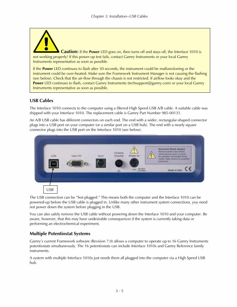
USB Cables
The Interface 1010 connects to the computer using a filtered High Speed USB A/B cable. A suitable cable was
shipped with your Interface 1010. The replacement cable is Gamry Part Number 985-00131.
An A/B USB cable has different connectors on each end. The end with a wider, rectangular-shaped connector
plugs into a USB port on your computer (or a similar port on a USB hub). The end with a nearly square
connector plugs into the USB port on the Interface 1010 (see below).
The USB connection can be “hot-plugged.” This means both the computer and the Interface 1010 can be
powered-up before the USB cable is plugged in. Unlike many other instrument system connections, you need
not power down the system before plugging in the USB.
You can also safely remove the USB cable without powering down the Interface 1010 and your computer. Be
aware, however, that this may have undesirable consequences if the system is currently taking data or
performing an electrochemical experiment.
Multiple Potentiostat Systems
Gamry’s current Framework software (Revision 7.0) allows a computer to operate up to 16 Gamry Instruments
potentiostats simultaneously. The 16 potentiostats can include Interface 1010s and Gamry Reference family
instruments.
A system with multiple Interface 1010s just needs them all plugged into the computer via a High Speed USB
hub.
Caution: If the Power LED goes on, then turns off and stays off, the Interface 1010 is
not working properly! If this power-up test fails, contact Gamry Instruments or your local Gamry
Instruments representative as soon as possible.
If the Power LED continues to flash after 30 seconds, the instrument could be malfunctioning or the
instrument could be over-heated. Make sure the Framework Instrument Manager is not causing the flashing
(see below). Check that the air-flow through the chassis is not restricted. If airflow looks okay and the
Power LED continues to flash, contact Gamry Instruments ([email protected]) or your local Gamry
Instruments representative as soon as possible.
USB

Chapter 3: Installation--Cell Cable Installation
3 - 6
Gamry’s Interface Power Hub is an especially convenient tool for organizing a system containing up to eight
Interface family instruments. It includes a 10-port USB hub and 48 V power-distribution in a rack designed to
hold the instruments. Unlike most instruments with multiple potentiostats in one box, you can easily remove
the Interface instruments in an Interface Power Hub for temporary use elsewhere in your laboratory.
Contact our main office or your local Gamry Instruments representative if you need assistance configuring a
system containing an Interface 1010 and different Gamry potentiostats.
Heat can be a problem in a multiple-potentiostat system. This subject is discussed in detail in Appendix E of
this manual.
Cell Cable Installation
The Cell Cable connector is a 25-pin female D-connector on the front of the Interface 1010.
All Gamry standard cell cables have a 25-pin D-connector on one end and a number of leads terminated with
banana plugs on the other. The D-connector end of the cable is connected to the Cell Cable port on the front
of the Interface 1010. Always use the knurled screws on this cable to hold the cable in place.
A wide variety of cell cables are available for the Interface 1010. These include shielded cables in various
lengths and special cables for use in EIS systems where very low impedances must be measured. The Interface
1010 can automatically detect which Gamry Instruments cable is connected, and the Gamry Framework
software can then adjust the system performance for the characteristics of that cable.
Front Panel USB LED
The front panel USB LED provides a simple test of two aspects of normal Interface 1010 USB operation. It has
four normal states:
We do not recommend using bus-powered hubs to expand your USB network: an externally
powered USB hub is required. Suitable hubs are available at most computer retailers.
Cell Cable connector USB LED

Chapter 3: Installation--Running the Framework
3 - 7
• Unlit The USB cable is disconnected or the USB connection is disabled by the host computer,
• Continuous
green
A valid cable connection has been made and the Interface 1010 USB processor is
receiving power from the USB cable,
• Flashing yellow Valid USB messages are being transferred between the computer and the Interface
1010,
• Continuous red A software download is in progress, or a USB communications error.
The flashing state only occurs when Gamry Instruments application software is running.
Running the Framework
Many newer electrochemical applications do not run as an application within Gamry’s Framework software.
This is true of all applications that use Gamry’s Toolkit for instrument control. Gamry’s Framework software is
the main application software for performing routine analysis associated for electrochemical measurements.
There are other software programs such as Resonator that are stand-alone programs. Programs that you
develop using our toolkits will fall into the stand-alone software category.
The Framework Instrument Manager is useful in organizing the potentiostats in the system. The Framework
also has a Calibration program that is used to calibrate instruments connected to the system.
Framework Device Status Bar
By default, the Gamry Framework shows a Device Status Bar under its main menu (see Figure 3-3). If you do
not see the Device Status Bar when you run the Gamry Framework, it has been disabled in the Framework
Options menu.
Potentiostat Devices (instruments) that are connected to the computer appear on this bar. The round indicator
associated with each device shows its status:
Green The device is available to run experiments
Orange The device is currently running an experiment
White The device is connected to the system, but is not usable. This is generally the result of a mismatch
between the Framework software and the device’s firmware. You can use the Gamry Instrument
Manager to fix the mismatch.
The screen capture below shows a Framework screen with three USB instruments connected.

Chapter 3: Installation--Types of Interface 1010 instruments
3 - 8
Figure 3-3
Framework with Three Potentiostats and One Running Test
The Interface 1000 (IFC 01004) in this system is shown with a green indicator because it is installed and ready
to run. The Reference 600 labeled My Ref600 has a red indicator because it is recording the EIS spectrum
shown on the screen. The Reference 600 labeled Jims Ref600 has a white indicator, showing it is plugged in
but cannot be used. This is an indication of a version mismatch between firmware and instrument.
Types of Interface 1010 instruments
The Interface 1010 comes in three models, the Interface 1010T, Interface 1010B, and Interface 1010E. You
can purchase an upgrade from one version to the next. To use the upgraded Interface 1010, enter a new
authorization code using Instrument Manager. See Appendix G for a full list of each model’s capabilities.
You can use Gamry’s Instrument Manager Application to make changes to the configuration of your Interface
1010 system. Find the application through the Options menu in the Gamry Framework.
The Instrument Manager is used to:
• Rename potentiostats
• Delete potentiostats that are not currently connected to the computer
• Select the order in which potentiostats appear in menus
• Upgrade the potentiostat model from one Interface 1010 to another
• Update firmware within potentiostats
Authorization Codes and Label
If you upgrade your Interface 1010 potentiostat or you need to make a correction to your authorization codes,
use the Framework Instrument Manager.
If you change the USB port used to connect the Interface 1010 to your computer, the Windows Device
Manager interprets an Interface 1010 on a new USB port as a new Interface 1010.

Chapter 3: Installation--Firmware Update
3 - 9
Firmware Update
Your Interface 1010 was shipped with the latest version of all its firmware. From time to time, Gamry makes
changes to the instrument’s firmware code and a firmware update is required to make use of the new or
improved code.
There are three separate firmware images that can be updated in the field on your Interface 1010. The first is
the Instrument Firmware. This is the program that handles most of the functions of the Interface 1010. The
second is the Communications Firmware. This program handles the USB communications between your
Interface 1010 and the host computer. The third is the PLD firmware, which you should only change if a
Gamry Instruments representative instructs you to.
Initiate the Firmware Update process using the Gamry Instruments’ Instrument Manager software.
Appropriate update files can be obtained from the Gamry Instruments website at www.gamry.com. If you
encounter a problem updating the firmware in your Interface 1010, please contact Gamry Instruments for
assistance.
The Interface 1010 Customization Label
Introduction to the Interface 1010 Customization Label
Modern electrochemical testing often involves replicate tests designed to measure or minimize the effect of
irreproducibility in the measurements. Battery tests are a good example, where multiple tests of a particular
battery composition and/or construction are generally required. Multiple potentiostat systems are often used to
speed up the testing process. If the multiple potentiostats can be randomly located in the lab, potentiostat
identification can be a problem. You may need to know “Is the potentiostat to the left of my host computer
the second or third potentiostat in the system?
The Interface 1010 includes a customization label that makes each unit visually unique. This allows you to
know exactly which potentiostat will be used for each test. You can easily place other labels in the instrument’s
Customization Label area. In a system containing eight potentiostats, the potentiostats might be labeled Pstat
1, Pstat 2, Pstat 3, ... Pstat 8.
Insert simple paper labels in an area behind the clear plastic outer layer of the front panel. The paper is behind
the plastic, so it is not affected by the lab environment. Best of all, you can edit or print the labels so personal
labels, like Bob’s Stat, are also possible.
There are several versions of the Interface 1010. If you upgrade from an Interface 1010B to an Interface
1010E, you may also remove the B label from the top, and replace it with an E.
Label Sheet Provided with Each Interface 1010
Every Interface 1010 is shipped with a preprinted label sheet containing:
Caution: Interrupting a firmware update can cause a catastrophic failure of your system.
Do not turn off the Interface 1010, do not unplug the USB cable, and do not stop the operation of the host
computer when the USB LED is a continuous red color.
Do not interrupt a firmware update that is in progress. An incomplete update can render an Interface 1010
inoperable until it is returned to Gamry for reprogramming.
Should the firmware update be interrupted, contact Gamry before starting the return process.

Chapter 3: Installation--The Interface 1010 Customization Label
3 - 10
• Instructions on how to change the label
• The first eight letters of the Greek alphabet (alpha through theta)
• The eight planets in the solar system (Mercury through Neptune)
• Several blank white labels
• Pstat 1 through Pstat 16 on a blue background
• Pstat 1 through Pstat 16 on a red background
You can cut any of these labels from the sheet and insert as the Interface 1010 Customization Label. The white
labels are provided to allow you to handwrite a label.
Procedure to Change a Label
These instructions apply to all current members of the Gamry Instruments Interface family. Don’t be confused
because some of the pictures were taken using an Interface 1010.
1) If you are making a custom-printed label, edit the Excel® file and print a label sheet as described
above. If you are using the Gamry-supplied label sheet, identify the location on the sheet where the
new label is found.
2) If you are writing by hand on a blank label, do it now.
3) Use scissors to cut out the new label. Cut white labels on the black lines.
4) Power down the Interface 1010 that is receiving the new label.
5) Remove the instrument’s rubber front bezel (the rubber frame around the front panel). No tools are
required. See Figure 3-5.
Figure 3-5
Removing the Front Bezel
6) Grip the bezel as shown in the Figure and pull the bezel away from the front panel. Some force is
required. Don’t worry about ripping the bezel; it is quite rugged. There is a 5 mm ear on either side
of the instrument that keeps the bezel in place.

Chapter 3: Installation--The Interface 1010 Customization Label
3 - 11
7) Your Interface 1010 family instrument should now look like Figure 3-6 (the front bezel is removed).
Notice the blue tab on the left side on the instrument. This is part of the old label; it is blue on the
instrument in the photo.
8) Pull gently on the paper tab on the left side of the front panel to remove the existing label. You need
to pull out about 5 cm of label.
9) Insert the new label in the same spot as the old label. The text should face the front of the instrument.
A small tab of paper will extend beyond the instrument’s front panel.
10) Examine the new label’s position in the Interface 1010 Front Panel. Adjust the label if needed.
11) Replace the rubber bezel. Make sure that the foot side of the bezel is toward the bottom of the
instrument.
12) Rename the Interface 1010 in the Gamry Framework software to match the new label. Use the
Framework Options, Instrument... dialog box. In the resulting dialog box, select the device you want
to rename and then select the Device Settings... button.
Figure 3-6
Instrument with Bezel Removed - Label Tab Seen

Chapter 3: Installation--The Interface 1010 Customization Label
3 - 12

Chapter 4: Calibration--Introduction
4 - 1
Chapter 4: Calibration
Introduction
There are two different types of calibration for the Interface 1010 potentiostat:
• Instrument DC calibration
• Cable calibration
Calibration can be initiated through Framework™ software, or directly through Gamry Instrument Manager
(GIM). Gamry recommends calibrating the instrument at least once per year, or when the quality of your data
is in question. To initiate calibration, take the following steps:
Click the Calibrate in Framework button, located in the Calibration area of GIM. This launches the
appropriate calibration routine for the instrument selected in GIM. Follow the instructions given in Framework.
See the relevant Calibration Quick Start Guide for additional details.
If there are any failures during calibration, click the Email Results to Gamry Support button in GIM. One of
our support engineers will review the results and provide appropriate advice.
You run the Instrument Manager by selecting Options/Instrument Manager... on the Framework Menu.
Calibrate each potentiostat installed in your system. A calibration utility is provided with the Gamry
Framework.
The calibration for the Interface 1010 is divided into two sections: Instrument DC Calibration and cable
calibration. Gain access to these calibration procedures via the Utility selection on the Framework’s
Experiment drop-down menu.
DC Calibration
Calibrate each potentiostat installed in your system. A calibration utility is provided with the Gamry Framework
software. Get access to the calibration procedure via the Utility selection on the Framework’s Experiment
drop-down menu.
This procedure uses an external resistive dummy cell.
Caution: The standard Interface 1010 calibration calls for an external resistive dummy
cell. Your Interface 1010 was shipped with Calibration Cell, which includes a 2 kΩ, 0.05% accurate resistor.
After calibration, please place this dummy cell in a safe place where you can find it if your unit requires
recalibration.
If you do need to recalibrate and you cannot find your calibration cell, you can perform DC Calibration
using a different 2 kΩ resistor. Its power-rating is unimportant. Some performance checks in the calibration
process may fail if the resistors inaccuracy exceeds 0.2% (4 Ω).

Chapter 4: Calibration--DC Calibration
4 - 2
Potentiostat calibration is only required infrequently. Recalibrate your Interface 1010 under the following
circumstances:
• It is at least one year since your last calibration.
• Your potentiostat has been serviced.
• You notice breaks or discontinuities in the data curves recorded with your system.
• The system is being run in an environment that is very different from the previous operating environment.
For example, if the Interface 1010 was calibrated at 15°C and you are now operating it at 30°C, you
should recalibrate.
Figure 3-4
2 kΩ Calibration Cell with Leads Attached for Calibration
Chapter 4: Calibration--Cable Calibration
4 - 3
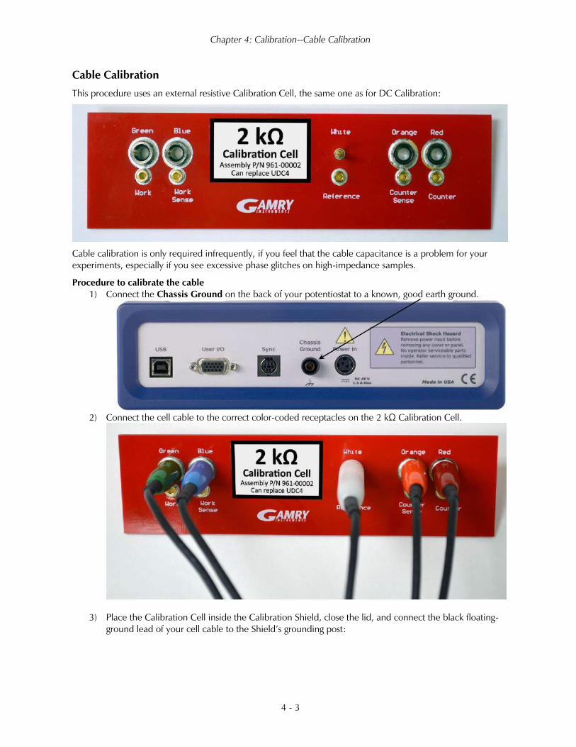
Cable Calibration
This procedure uses an external resistive Calibration Cell, the same one as for DC Calibration:
Cable calibration is only required infrequently, if you feel that the cable capacitance is a problem for your
experiments, especially if you see excessive phase glitches on high-impedance samples.
Procedure to calibrate the cable
1) Connect the Chassis Ground on the back of your potentiostat to a known, good earth ground.
2) Connect the cell cable to the correct color-coded receptacles on the 2 kΩ Calibration Cell.
3) Place the Calibration Cell inside the Calibration Shield, close the lid, and connect the black floating-
ground lead of your cell cable to the Shield’s grounding post:

Chapter 4: Calibration--Cable Calibration
4 - 4
4) Open Gamry Framework™ software. Select Experiment > Named Script...
The Select a script to run window appears.
5) From the list of scripts, choose
calcable.exp, then click the Open
button.
The Cable Capacitance Calibration window
appears.
6) In the Cable Tag field, enter
a unique name for the cable
you are calibrating.
Choose the desired Action
radio button:
• To calibrate the cable,
choose Cal Cable.
• To reset the vales to zero
(if, say, the calibration
doesn’t work), choose Zero Values.
Click the OK button.
The Performance Tips window appears.

Chapter 4: Calibration--Cable Calibration
4 - 5
7) Make sure that all of the tips are true, then
click the OK button.
The Cell Required window appears.
8) Make sure that the correct Calibration Cell is attached,
then click the OK button.
The calibration runs.
The Done window appears.
9) Click the OK button to acknowledge completion.

Chapter 4: Calibration--Cable Calibration
4 - 6

Chapter 5: Cell Connections--Normal Cell Connections
5 - 1
Chapter 5: Cell Connections
Normal Cell Connections
Each Interface 1010 in your system was shipped with a standard, shielded cell cable (part number 985-00071).
It is a 60 cm complex cable with a 25-pin D-type connector on one end and four banana plugs and two pin
jacks on the other end.
In some cases, your system may also include a special-purpose cell cable. The special purpose cell cable
includes documentation describing its use.
The 25-pin male end of the standard cell cable connects to the Interface 1010’s front panel Cell Cable
connector.
Always affix the cell cable into place with the two screws, because this cable can fall off the unit. This can be
disastrous if it occurs during an experiment.
The other end of the cell cable terminates in a number of banana plugs and two pin jacks. Each termination
comes with a removable alligator clip. Table 5-1 identifies each terminal of the cable.
Table 5-1
Cell Cable Terminations - Potentiostat and Galvanostat Modes
Color Type Name Normal Connection
Blue Banana plug Working Sense Connect to working electrode
Green Banana plug Working Electrode Connect to working electrode
White Pin jack Reference Connect to reference electrode
Red Banana plug Counter Electrode Connect to counter electrode
Orange Banana plug Counter Sense Used in ZRA mode; connect to counter electrode
Black Pin jack Floating Ground Leave open or connect to a Faraday shield
Connect both the blue and green cell leads to the working electrode. The working electrode is the specimen
being tested. The blue banana-plug connection senses the voltage of the working electrode. The green working-
electrode connection carries the cell current. The working electrode may be as much as 150 mV above the
circuitry ground (Chassis Ground).
Connect the white pin jack to the cell’s reference electrode, such as an SCE or Ag|AgCl reference electrode.
The measured cell potential is the potential difference between the blue and white cell connectors.
Connect the red banana plug to the counter or auxiliary electrode. The counter electrode is usually a large inert
metal or graphite electrode. The counter electrode terminal is the output of the Interface 1010 power amplifier.
The orange lead is only used in ZRA mode, where it senses the counter-electrode potential (see following
section). Automatic switching to ZRA mode is possible if this lead is connected to the counter electrode. If you
are not using ZRA mode, leave this lead open as long as you ensure that it will not short against any other
electrode.
The black pin jack is connected on the Interface 1010 end to Chassis Ground. This is the circuitry ground for
the analog circuits in the Interface 1010. In most cases, leave this terminal disconnected at the cell end. When
you do so, take care that its metal contact does not touch any of the other cell connections.

Chapter 5: Cell Connections--ZRA-Mode Cell Connections
5 - 2
If your cell is a typical glass laboratory cell, all of the electrodes are isolated from earth ground. In this case, you
may be able to lower noise in your data by connecting the Interface 1010’s Chassis Ground to an earth
ground.
If you are measuring very small currents, you may find that a metal enclosure completely surrounding your cell
(a “Faraday shield”) significantly lowers measured current noise. Normally you connect this Faraday shield to
both earth ground and floating ground. The floating ground on the black cell lead is a convenient source of
ground.
If any electrode in your cell is connected to earth ground, only connect your Faraday shield to the black cell
lead (Chassis Ground).
You can remove the alligator clip on any cell connection to gain access to the underlying banana plug or pin
jack. Gamry Instruments also can provide additional standard or special cell cables.
In either potentiostatic or galvanostatic mode, if you do not have a reference electrode in your cell, the
reference lead can be connected to the counter electrode for a two-electrode experiment. The potential
reading then is the difference between the counter electrode and the working electrode.
ZRA-Mode Cell Connections
The Interface 1010 can function as a precision Zero-Resistance Ammeter (ZRA). It maintains two metal samples
at the same potential and measures the current flow between the samples. It can also measure the potential of
the samples versus a reference electrode.
The cell cable connections for ZRA mode are shown in Table 5-2. The connections are very similar to those for
the potentiostat and galvanostat modes. A second working electrode is substituted for the counter electrode and
the Orange Counter Sense lead must be connected.
Warning: Make sure that your earth-ground connection is made to a legitimate source of
earth ground. Consult a qualified electrician if you are uncertain how to obtain an earth ground.
Connecting the Interface 1010 to an incorrect and unsafe voltage can create a safety hazard (see Chapter 1
for details).
Caution: If any electrode in your cell is at earth ground, never connect the Interface 1010
chassis to earth ground. Autoclaves, stress apparatus, and field measurements may involve earth-grounded
electrodes. A binding post on the rear panel of the Interface 1010 is provided for this purpose. A water
pipe can be a suitable earth ground.

Chapter 5: Cell Connections--Membrane Cell Connections
5 - 3
Table 5-2
Cell Cable Connections for ZRA Mode
Color Type Name Normal Connection
Blue Banana plug Working Sense Connect to metal sample #1
Green Banana plug Working Electrode Connect to metal sample #1
White Pin jack Reference Connect to a reference electrode
Red Banana plug Counter Electrode Connect to metal sample #2
Orange Banana plug Counter Sense Connect to metal sample #2
Black Pin jack Floating Ground Leave open or connect to a Faraday shield
The counter sense and the working sense lead are each connected to different metal samples. In the ZRA mode
the Interface 1010 is normally programmed to maintain zero volts between these leads. It therefore maintains
the two metal samples at the same voltage.
The white pin jack on the cell cable is normally connected to a reference electrode. The potential between this
lead and the working sense lead is reported as the cell potential.
In ZRA mode, if you do not have a reference electrode in your cell, we recommend that you connect the white
reference lead to the working electrode. In theory, the measured potential is exactly zero when this is done. In
practice, A/D noise and offset create a small potential signal with a value very close to zero.
Membrane Cell Connections
The Interface 1010 can be used with membrane cells. In this type of cell, a membrane separates two electrolyte
solutions. Two reference electrodes are used: one in each electrolyte. Each electrolyte also contains a counter
electrode. The Interface 1010 controls the potential across the membrane. Table 5-3 shows the cell connections
used with a membrane type cell.
Table 5-3
Cell Cable Connections for a Membrane Cell
Color Type Name Normal Connection
Blue Banana Plug Working Sense Connect to reference electrode #1
Green Banana Plug Working Electrode Connect to counter electrode #1
White Pin Jack Reference Connect to reference electrode #2
Red Banana Plug Counter Electrode Connect to counter electrode #2
Orange Banana Plug Counter Sense Leave open (only needed in ZRA mode)
Black Pin Jack Floating Ground Leave open or connect to a Faraday shield
Reference electrode #1 and counter electrode #1 must be on one side of the membrane,
and reference electrode #2 and counter electrode #2 must be on the other side.

Chapter 5: Cell Connections--Membrane Cell Connections
5 - 4

Chapter 6: Panel Indicators and Connectors--Front Panel
6 - 1
Chapter 6: Panel Indicators and Connectors
Front Panel
Power Switch
The Power button is on the far right side of the Interface 1010 Front Panel. It is a push-push switch: push once
to turn the instrument on and push again to turn the instrument off. The switch’s button latches: the button is
closer to the front panel when the instrument is on than when it is off.
Normally the Power LED illuminates when the Interface 1010 is powered on; see the Power LED description
below.
Normally, the DC power is connected before the Power button is turned ON. However, no damage occurs if
this switch is already in the ON position when the cable is connected to Power In, or when the AC power input
is connected to the external power supply.
The Power LED
The Power LED is on the lower right of the Interface 1010 front panel. It normally glows a continuous blue
when the Interface 1010 is turned on and has passed some simple power-on tests.
When the Interface 1010 is first turned on, the Power LED glows steadily for a second or two, blinks three
times, and then goes to its normal steady blue output.
When the Power LED is off, these are possible causes:
Caution: Avoid touching the Power switch button during normal instrument operation.
Data are lost if the instrument is accidentally powered off during an experiment.
The Interface 1010 uses three DIN connectors for connections to external devices. The three
DIN connectors all have different numbers of pins and physical sizes, so the cables used in them cannot be
interchanged or improperly connected.
Power button Power LED

Chapter 6: Panel Indicators and Connectors--Front Panel
6 - 2
• The Power button is off.
• There is no DC +48 V supply connected to the rear panel Power In connector.
• The external DC power supply has no input power or is malfunctioning.
• One part of the Power PC’s power-up self-test has failed.
An Interface 1010’s Power LED blinks when that instrument is selected in the Framework’s Instrument
Manager. This allows easy identification of a specific instrument in a Multichannel system without looking at the
instrument Serial Label on the bottom of the instrument chassis.
Finally, the Power LED continuously blinks if the instrument is subject to an over-temperature condition. In this
case, the instrument is not usable until it has been powered down, allowed to cool, and restarted.
Cell Cable Connector
The Cell cable connector is a 25-pin D type connector used to connect the Interface 1010 to an
electrochemical test cell. It is normally used with a Gamry Instruments supplied cell cable.
In addition to the pins used for cell connections, the Interface 1010 Cell Connector also uses four pins to read a
cell cable ID. Gamry software can compensate for the cell cable characteristics for optimal system performance,
especially in EIS (Electrochemical Impedance Spectroscopy).
The cell connections are discussed at great length in Chapter Error! Reference source not found.. A pin-out of
the Cell Cable connector can be found in Appendix B.
Monitor Connector
The Monitor Connector is an 9-pin DIN-type connector. It contains two analog output signals; one analog input
signal is used for connection of the Interface 1010 to external devices, a temperature input, and an analog input
for measurement of analog input signals. It is not needed for any standard Gamry Framework electrochemical
tests.
Additional information on this connector, its uses, and its signals is in Appendix C.
The USB LED
The USB LED is located just below the Power LED. It is a tri-color LED, able to glow green, orange, or red.
Caution: The Power LED indicates power status, power-up tests have passed, to identify
instruments, and to indicate latch-up caused by an over-temperature event. Never rely on the PWR LED as
a true power-status indicator. Always unplug the Power In connection if you suspect your Interface 1010 is
malfunctioning.
Monitor connector Cell Cable connector

Chapter 6: Panel Indicators and Connectors--Front Panel
6 - 3
The USB LED is unlit when:
• The Interface 1010 is not powered.
• The Interface 1010 does not have a USB cable plugged into its rear-panel USB port.
• The computer end of the USB cable is not plugged into a USB port on a computer or hub.
• The USB cable is not supplying USB power to the Interface 1010.
• The computer has disabled the USB port going to the Interface 1010.
The USB LED glows a continuous green if a valid USB connection is made and the Interface 1010’s
communication processor receives power along the USB cable.
The USB LED flashes orange whenever the Interface 1010 receives or transmits valid USB messages to or from
the host computer. It does not flash if there is USB traffic addressed to other devices on the USB bus, including
messages aimed at a different Interface 1010.
The USB LED indicates a continuous red in one special condition: when a firmware update occurs. Interrupting
a firmware update can cause a catastrophic failure of your system. Do not turn off the Interface 1010, do not
unplug the USB cable, and do not stop the operation of the host computer when the USB LED is a
continuous red color.
Cell On LED
The Cell On LED is to the left of the Cell Cable connector.
The Cell On LED glows yellow whenever the Interface 1010 is actively applying voltage or current to the
electrochemical cell attached to the Cell Cable. Avoid touching the cell cable leads whenever the Cell On LED
is lit, because the quality of the data being collected in your experiment may be compromised.
The Cell On LED does not indicate a dangerous condition when it is lighted. The voltages
generated by the Interface 1010 are generally considered safe. Still, avoid touching the cell leads when the
cell is on.
Caution: Do not interrupt a firmware update while it is in progress. An incomplete update
can render an Interface 1010 inoperable until it is returned to Gamry for reprogramming.
USB LED Cell On LED

Chapter 6: Panel Indicators and Connectors--Front Panel
6 - 4
If you need to make changes to your cell leads, do so between experiments, when the Cell On LED is off and
the potentiostat is inactive.
In a typical experimental sequence, the Cell On LED is off between experiments and during any open-circuit
potential measurements. It glows yellow whenever the cell is polarized.
Overload LED
The Overload LED is just below the Cell On LED.
The Overload LED is normally unlit. When it glows red, a circuit in the Interface 1010 has exceeded its normal
operating limit. Conditions that generate Overloads include:
• The absolute value of the differential electrometer output voltage (the difference in voltage between
the Working and Reference leads) exceeds 11 V. This condition is known as an E Overload.
• The control amplifier has lost control of the cell. The absolute value of the cell current may be trying to
exceed 1 A, or the absolute value of the counter electrode voltage may be trying to exceed 22 V.
Either condition is a Control Overload.
• The absolute value of the cell current has exceeded full scale on the current range presently in use.
This condition is an I Overload.
Transient (temporary) overloads during an experiment in which the cell voltage or current is being stepped or
swept are often normal. In most cases, they do not indicate a system or instrument malfunction.
Consider the case of an infinitely-fast voltage step into a perfect capacitor. In theory, charging a perfect
capacitor requires an infinite current. The current spike seen at each step in a stepped voltage waveform can
easily illuminate the Overload LED. The current spike normally decays to near zero before the actual current
and voltage readings are taken.
Overload indications when the cell is being connected or disconnected are common and usually do not
indicate a problem. Overloads can also be seen when one of the cell leads is disconnected from the other cell
leads, even though the cell is off. Again, this does not indicate a problem.
A steadily glowing Overload LED during an experiment most likely indicates a problem is occurring. Possible
causes include:
• One of the cell leads is disconnected (this is the most common cause),
• A gas bubble in the cell is blocking one of the electrodes,
• The potentiostat could be oscillating.
Overload LED

Chapter 6: Panel Indicators and Connectors--Rear Panel
6 - 5
Customization Label Area
The left side of the Interface 1010 front panel has a transparent area in its plastic overlay. A paper label behind
this area allows a custom appearance. This is especially important when the instrument is in a multiple-
potentiostat system.
By default, the label in this area shows the instrument’s serial number written in white text on a blue
background. You can choose a different label. A sheet of alternate labels is provided with each instrument and a
user-editable Excel file can be found on the Gamry website.
Full instructions describing the process of changing a label are near the end of the Installation chapter (Chapter
3).
Rear Panel
Power In Jack
The Power In jack is a 4-pin power DIN connector. The Interface 1010 derives all its power from +48 V DC
input through the Power In jack. The input current is less than 1.5 A.
Always use the external power supply supplied with your Interface 1010 or power from an Interface Power Hub
to supply DC power to the instrument.
A glowing red Overload LED does not necessarily indicate a system malfunction. The
Overload LED can illuminate when one or more cell leads are disconnected, without indicating a problem
with the system. The Overload LED can often illuminate momentarily during a swept or stepped
experiment. The only Overload LED indication that definitely points towards a problem is a continuously
glowing Overload LED during an experiment.
Customization Label Area
Power In Jack

Chapter 6: Panel Indicators and Connectors--Rear Panel
6 - 6
The external power supply is rated for operation from 100 to 240 V AC, at frequencies from 47 to 63 Hz. It
should therefore be useable worldwide.
Chassis Ground
The rear panel Chassis Ground banana jack is intended for one use only. When the Interface 1010 is used with
cells isolated from earth ground, connecting the chassis ground to earth ground may lower the noise measured
in the system. Note that the chassis of the Interface 1010 is connected to floating ground. Safety information
concerning this is in Chapter 1.
A banana plug is the only way you can connect to the Chassis Ground jack. Use a wire to connect the banana
plug to earth ground.
A black banana-plug-to-banana-plug lead is provided with your Interface 1010. You may find it useful when
making this earth-ground connection.
USB Port
The USB port on the rear panel of the Interface 1010 is a Type B connector as defined in Revision 1.1 and 2.0
of the USB Specification. Use a standard, shielded, Type A/B cable to connect this port to a computer’s USB
port or a USB hub (preferably an externally powered hub). The two ends of a Type A/B cable are different. The
more-rectangular end plugs into the computer and the more-square end plugs into the Interface 1010.
A suitable USB cable was included with your Interface 1010 shipment. If this cable is lost, you can replace it
with a cable from your local computer retailer.
The Interface 1010 is a High Speed USB 2.0 peripheral, capable of data-transfer at 480 Mbits/second. If it is
plugged into a computer port incapable of High Speed operation it will downgrade to USB 1.1 full-speed
operation (12 Mbits/second), causing slower data-transfer. The Interface 1010 USB port is compatible with
Revision 1.1 and 2.0 of the USB specification. It supports the Windows Plug-n-Play mechanism, including
dynamic connect/reconnect.
The front panel USB LED should be green whenever a valid computer to Interface 1010 connection is made
and both the computer and Interface 1010 are fully powered.
Caution: Power input voltages less than 40 V or greater than 52 V can damage the
Interface 1010’s power supply.
Chassis Ground Jack

Chapter 6: Panel Indicators and Connectors--Rear Panel
6 - 7
User I/O Connector
The User I/O connector contains digital signals used to connect external devices to the Interface 1010. All of its
signals are referenced to earth ground so their connection does not compromise the Interface 1010 ground
isolation.
A full description of this connector is in Appendix C of this manual. This appendix includes details such as
connector pin-out, output and input voltage levels, and full signal descriptions.
The following list is a short description of the signals in the User I/O Connector and their uses:
• A 12-bit D/A converter used to set “continuously variable” settings such as electrode rotation rate on a
rotating disc electrode.
• Four digital outputs can be used to turn on external devices under control of an Explain experimental
control script.
• Some of Gamry applications assign three of the digital outputs to control stirring, flow of de-aeration
gas, and formation of mercury drops on a mercury-drop electrode.
• Four digital inputs that can be read in an Explain experimental control script.
• An analog output voltage. The output is generated by a 12-bit digital-to-analog converter with an
output span from 0 to 4.096 V.
• This connector includes a 5 V power supply that can provide up to 50 mA of current for external
circuitry.
Sync Port
The Sync Port is used when several Interface 1010 instruments need to be operated with a common clock and
simultaneous data acquisition. It is an 8-pin mini-DIN connector.
Simultaneous operation is only required when several instruments are connected to a single electrochemical
cell. Examples include rotating ring-disk voltammetry, series flow cells, localized EIS systems, and
electrochemical microscopy. In these examples, data acquisition starts and stops on all the system’s
potentiostats simultaneously, and any excitation signals are closely coupled to data-acquisition.
Simultaneous operation is generally not required when instruments are connected to different electrochemical
cells. A good example is parallel testing of batteries. You might want to start a number of tests simultaneously,
but the tests need not remain synchronous and they can end independently.
Caution: Floating operation of Interface 1010 can be compromised by improper
connections to the User I/O Connector. We do not recommend use of standard 15-pin shielded cables
with this connector. Custom cables with the shield connected to pin 6 of the D-connector are preferred.
User I/O Connector

Chapter 6: Panel Indicators and Connectors--Rear Panel
6 - 8
A full description of the Sync Port is in Appendix C of this manual.

Chapter 7: Instrument Circuitry--Interface 1010 Schematic/Block Diagrams
7 - 1
Chapter 7: Instrument Circuitry
Interface 1010 Schematic/Block Diagrams
If you are not familiar with electronic schematics or potentiostats, you probably want to skip this chapter. This
information is for expert use only and is not required for routine use of the Interface 1010.
The following figures are partly schematic diagrams and partly block diagrams. They are intended to show the
basic principles of the Interface 1010 without the confusion of the full circuitry details. The complexity of the
Interface 1010 can be quite daunting: the Interface 1010 circuit boards contain more than 2000 components
connected by almost 5000 circuit nets.
The schematic/block diagram figures show:
• The Interface 1010 in its potentiostatic control mode,
• The circuits for signal generation,
• The circuits for signal conditioning and A/D conversion,
• The processors in the Interface 1010,
• DC-DC power conversion.
Warning: If your instrument malfunctions, Gamry Instruments does not recommend user
repair. The information provided here is not sufficient for troubleshooting problems in an Interface 1010.
Contact Gamry Instruments at [email protected] or your local Gamry representative if you have
problems.

Chapter 7: Instrument Circuitry--Interface 1010 Schematic/Block Diagrams
7 - 2
Figure 7-1
Interface 1010 Potentiostat Board in Potentiostat Mode
Notes for Figure 7-1
• Only Potentiostat Mode circuitry is shown in this figure. In this mode the voltage difference between the
Reference and Working Sense leads (called Esig) is fed back into the control amplifier.
In Galvanostat Mode, the feedback is from Isig.
In ZRA mode, the feedback is from a differential amplifier measuring the difference between the Counter
Sense and Working Sense leads of the cell cable. The counter sense circuitry is not shown. It is conceptually
similar to the voltage sensing circuit that generates Esig.
• Switches are either computer controlled reed relays or MOS switches as appropriate.
• All components shown as variable (resistance Rm, capacitor IEStab and capacitor CASpeed) are actually
several fixed-value components switched into the circuit. They are not continuously variable as implied in
the figure.
• The monitor connections for Isig and Esig are filtered using an RLC circuit.
• All the resistors summing voltages into the Control Amplifier input do not have values shown; their values
depend on scaling factors too complex to discuss in this simplified diagram.
• Calibration components are not shown.
• Overload protection and overload detection are not shown. Good engineering practice demands that any
possible misconnection of the cell leads will not damage the instrument. This practice has been followed in
the design of the Interface 1010.

Chapter 7: Instrument Circuitry--Interface 1010 Schematic/Block Diagrams
7 - 3
Figure 7-2
Interface 1010 Signal-Generation Circuitry
Notes on Figure 7-2:
• All the resistors summing voltages into the Summing Amplifier input do not have values shown because
their values depend on scaling factors too complex for this simplified diagram.
• Calibration components are not shown.
• High-frequency sine-wave generation is done using a DDS (direct digital synthesis) IC. The DDS’s output is
filtered with both a high-pass and low-pass filter. The low-pass filter removes the steps in the DDS output.
The high-pass filter provides AC-coupling to prevent drift in the DDS’s offset getting into the applied signal.
In practice, Gamry EIS software uses the DDS to apply sine waves with frequencies between 100 Hz and 1
MHz. It uses the Scan DAC to generate sine signals at frequencies below 100 Hz.
A two-stage attenuator scales the DDS. On the coarse scale, the maximum output signal is 2.33 Vrms
(3.3
Vpeak) and the resolution is approximately 0.6 mVrms/bit. On the fine scale, the maximum is approximately
77 mVrms and the resolution is approximately 20 Vrms. AC-signal attenuation is handled automatically by
Gamry software.
• The Scan DAC and Bias DAC signals are filtered before they are applied to the cell. The filter bandwidths
are as shown.

Chapter 7: Instrument Circuitry--Interface 1010 Schematic/Block Diagrams
7 - 4
Figure 7-3
One A/D Signal Chain in the Interface 1010
Notes for Figure 7-3:
• This diagram shows one of two identical ADC channels. One channel is dedicated to measurement of
the potentiostat’s current signal and the other is used to measure the voltage signal.
• Both A/D converters are triggered simultaneously to start a conversion. This trigger and the pulse
updating the Scan DAC voltage are under the control of a hardware state-machine. This insures that all
waveform and data-acquisition timing is tightly controlled and reproducible point-to-point.
By default, the data acquisition is synchronized with the system’s 600 kHz power-supply switching-
frequency reducing noise from the power supply. Data-acquisition times that are a multiple of 1.666 µs
will maintain this synchronization.
• All analog signals are received differentially as shown here.
• The 5 Hz, 1 kHz, 10 kHz, 200 kHz and 1.4 MHz filters are two-pole Butterworth filters.
• The voltage-measurement channel includes a programmable 1×−0.25× gain circuit. In the 0.25 gain
position, voltages as high as 12 V can be measured.

Chapter 7: Instrument Circuitry--Interface 1010 Schematic/Block Diagrams
7 - 5
Figure 7-4
Microprocessors in the Interface 1010
Notes for Figure 7-4:
• Note the lack of a ground connection between the USB bus and the Interface 1010 circuitry.
• The USB Processor firmware is loaded into its RAM on power-up.
• The Power PC firmware is also transferred from ROM into RAM on power-up. Time-critical sections of
the Power PC code are kept in the processor’s fast cache memory.
• The term UART refers to a Universal Asynchronous Receiver Transmitter. It converts parallel data to a
serial bit-stream. The UARTs send data at 6 Mbits/second.
• The Interface 1010 has local non-volatile data storage. This is used to save calibration data and board-
revision information. Interface 1010 calibration data is stored in the instrument, not in a data file.
When an Interface 1010 is moved from one computer to another, its calibration remains valid.
• The FPGA code can be updated in the field over the USB connection.
• The Windows device manager can be used for field update of all three programmable parts: the USB
Processor, the Power PC, and the FPGA. Binary code for the updates can be obtained from the Gamry
Website. If you need assistance with field updates, contact Gamry technical support at
[email protected] or contact your local Gamry representative.

Chapter 7: Instrument Circuitry--Interface 1010 Schematic/Block Diagrams
7 - 6
Figure 7-5
Power Conversion
Notes for Figure 7-5:
• Note the ground isolation between the input power and the Interface 1010 circuitry. The Interface 1010
chassis is connected to the Floating Instrument Ground.
Transformers and digital isolators are the only components connected between the grounds.
• The 600 kHz power supply sync signal is derived from the same clock used to control data acquisition.
Data points taken at an integer multiple of 1.6666 µs/point will be synchronized with the power supply,
minimizing the effect of power supply noise on the data.
• The DC-DC Converter powers both the floating circuitry and some earth-side circuitry including the USB
processor and User I/O.
• Additional circuitry protects the Interface 1010 against ESD and electrical surges.
• Like most complex electronic apparatus, the Interface 1010 uses a variety of power supply voltages.
• The incoming DC voltage must be between 46 and 50 V. With inputs below 46 V, the PWM may be
unable to regulate the supply. Above 50 V, the PWM may not start-up.
Caution: Do not use a DC power source other than the AC adapter provided with your
Interface 1010 or a Gamry-supplied alternative. Other power sources may void the performance and/or
safety characteristics of the Interface 1010.
Power input voltages less than 40 V or greater than 52 V can damage the Interface 1010’s power supply.

Chapter 8: Stability in Potentiostat Mode--Capacitive Cells and Stability
8 - 1
Chapter 8: Stability in Potentiostat Mode
Capacitive Cells and Stability
All potentiostats can become unstable when connected to capacitive cells. The capacitive cell adds phase-shift
to the potentiostat’s feedback signal (which is already phase-shifted). The additional phase-shift can convert the
potentiostat’s power amplifier into a power oscillator.
To make matters worse, almost all electrochemical cells are capacitive because an electrical double-layer forms
next to a conductor immersed in a solution.
Potentiostat oscillation is an AC phenomenon. However, it can affect both AC and DC measurements.
Oscillation often causes excessive noise or sharp DC shifts in the system’s graphical output. The Interface 1010
Potentiostat can be stable on less-sensitive current ranges and unstable on more-sensitive current ranges.
Whenever you see sharp breaks in the current recorded on the system, you should suspect oscillation.
The Interface 1010 has been tested for stability with cell capacitors between 10 pF and 3000 F. In all but its
fastest control amplifier speed-setting, it is stable on any capacitor in this range—as long as the impedance in
the reference electrode lead does not exceed 20 k. With reference-electrode impedances greater than 20 k
the Interface 1010 may oscillate. The RC filter formed by the reference-electrode impedance and the reference
terminal’s input capacitance filters out the high-frequency feedback needed for potentiostat stability.
Longer cell cables make the problem worse by increasing the reference terminal’s effective input capacitance.
Even when the system is stable (not oscillating), it may exhibit ringing whenever there is a voltage step applied
to the cell. The Interface 1010’s D/A converters routinely apply steps, even when making a pseudo-linear ramp.
While this ringing is not a problem with slow DC measurements, it can interfere with faster measurements. The
steps taken to eliminate potentiostat oscillation also help to minimize ringing.

Chapter 8: Stability in Potentiostat Mode--Improving Potentiostat Stability
8 - 2
Improving Potentiostat Stability
There are a number of things that you can do to improve an unstable or marginally stable Interface 1010
potentiostat/cell system. This list is not in any particular order; any or all of these steps may help.
• Slow down the potentiostat. The Interface 1010 has five control-amplifier speed settings, which can be
selected in software. Slower settings are generally more stable.
• Increase the Interface 1010 I/E stability setting. The Interface 1010 includes three capacitors that can
be placed in parallel with its I/E converter resistors. These capacitors are connected to relays that are
under software control. Contact your local Gamry Instruments representative for more information
concerning changes in these settings.
• Lower the reference electrode’s impedance. Make sure that you do not have a clogged reference-
electrode junction. Avoid asbestos-fiber reference electrodes and double-junction electrodes. Avoid
small-diameter Luggin capillaries. If you do have a Luggin capillary, make sure that the capillary’s
contents are as conductive as possible.
• Add a capacitively-coupled low-impedance reference element in parallel with your existing reference
electrode. The classic fast combination reference electrode is a platinum wire and a junction-isolated
SCE. (See Figure 8-1.) The capacitor insures that DC potential comes from the SCE and AC potential
from the platinum wire. The capacitor value is generally determined by trial and error.
Figure 8-1
Fast Combination Reference Electrode
SCE Platinum
White
Cell Lead100 pF to 10 nF
Electrolyte

Chapter 8: Stability in Potentiostat Mode--Improving Potentiostat Stability
8 - 3
• Provide a high-frequency shunt around the cell. A small capacitor between the red and white cell
leads allows high-frequency feedback to bypass the cell. (See Figure 8-2.) The capacitor value is
generally determined by trial and error. One nF (1000 pF) is a good starting point.
In a sense, this is another form of an AC-coupled low-impedance reference electrode. The counter
electrode is the low-impedance electrode, eliminating the need for an additional electrode in the
solution.
Figure 8-2
High Frequency Shunt
R e d
W h ite
G re e n
1 0 0 p F to 1 0 n F
C o u n te rR e fe re n c e
W o rk in g

Chapter 8: Stability in Potentiostat Mode--Improving Potentiostat Stability
8 - 4
• Add resistance to the counter electrode lead. (See Figure 8-3.) This change lowers the effective
bandwidth of the control amplifier. As a rule of thumb, choose the resistor to give one volt of drop
at the highest current expected in the test being run. For example, if you expect your highest
current to be around 1 mA, you can add a 1 k resistor.
This resistor has no effect on the DC accuracy of the potentiostat. It can create problems in
high-speed experiments such as fast CV scans or EIS, which need high bandwidth.
Figure 8-3
Resistor Added for Stability
R e d
W h ite
G re e n
C o u n te rR e fe re n c e
W o rk in g
R e s is to r

Chapter 9: Measurement of Small Signals--Overview
9 - 1
Chapter 9: Measurement of Small Signals
Overview
The Interface 1010 is a very sensitive scientific instrument. It can theoretically resolve current changes as
small as 333 femtoamperes (333 x 10−15
A). To place this current in perspective, 333 fA represents the flow
of about 2 000 000 electrons per second!
The small currents measured by the Interface 1010 place demands on the instrument, the cell, the cables
and the experimenter. Many of the techniques used in higher-current electrochemistry must be modified
when used to measure pA currents. In many cases, the basic physics of the measurement must be
considered.
This chapter will discuss the limiting factors controlling low-current measurements. We offer hints on cell
and system design. The emphasis is on EIS (Electrochemical Impedance Spectroscopy), a highly demanding
application for the Interface 1010.
Measurement System Model and Physical Limitations
To get a feel for the physical limits implied by very sensitive current measurements, consider the equivalent
circuit shown in Figure 9-1. We are attempting to measure the cell impedance given by Zcell.
This model is valid for analysis purposes even though the real Interface 1010 circuit topology differs
significantly.
In Figure 9-1:
Es is an ideal signal source
Zcell is the unknown cell impedance
Icell is the “real” cell current
Rm is the current-measurement circuit’s current-measurement resistance
Rshunt is an unwanted resistance across the cell
Cshunt is an unwanted capacitance across the cell
Cin is the current-measurement circuit’s stray input capacitance
Rin is the current-measurement circuit’s stray input resistance
Iin is the measurement circuit’s input current
In the ideal current-measurement circuit Rin is infinite while Cin and Iin are zero. All of the cell current, Icell,
flows through Rm.
With an ideal cell and voltage source, Rshunt is infinite and Cshunt is zero. All the current flowing into the
current measurement circuit comes from Zcell.
The voltage developed across Rm is measured by the meter as Vm. Given the idealities discussed above, you
can use Kirchoff’s and Ohm’s law to calculate Zcell:
Zcell = Es × Rm / Vm

Chapter 9: Measurement of Small Signals--Measurement System Model and Physical Limitations
9 - 2
Figure 9-1
Equivalent Measurement Circuit
Ic e ll
C s h u n t
R s h u n t
C in R in
R m
Unfortunately, technology limits high-impedance measurements because:
• Current measurement circuits always have non-zero input capacitance, i.e., Cin > 0.
• Infinite Rin cannot be achieved with real circuits and materials.
• Amplifiers used in the meter have input currents, i.e., Iin > 0.
• The cell and the potentiostat create both a non-zero Cshunt and a finite Rshunt.
Additionally, basic physics limits high-impedance measurements via Johnson noise, which is the inherent
noise in a resistance.
Johnson Noise in Zcell
Johnson noise across a resistor represents a fundamental physical limitation. Resistors, regardless of
composition, demonstrate a minimum noise for both current and voltage, per the following equations:
E = (4kTRF)1/2
I = (4kTF/R)1/2
where
k = Boltzman’s constant, 1.38 × 10⁻²³
J/K
T = temperature in K
F = noise bandwidth in Hz
R = resistance in Ω.
For purposes of approximation, the noise bandwidth, F, is equal to the measurement frequency. Assume a
1011
Ω resistor as Zcell. At 300 K and a measurement frequency of 1 Hz, this gives a voltage noise of 41 µV
rms. The peak-to-peak noise is about five times the rms noise. Under these conditions, you can make a
voltage measurement of 10 mV across Zcell with an error of about 0.4%. Fortunately, an AC measurement
can reduce the bandwidth by integrating the measured value at the expense of additional measurement
time. With a noise bandwidth of 1 mHz, the voltage noise falls to about 1.3 µV rms.
Current noise on the same resistor under the same conditions is 0.41 fA. To place this number in
perspective, a 10 mV signal across this same resistor generates a current of 100 fA, or again an error of

Chapter 9: Measurement of Small Signals--Measurement System Model and Physical Limitations
9 - 3
up to 0.4%. Again, reducing the bandwidth helps. At a noise bandwidth of 1 mHz, the current noise falls
to 0.013 fA.
With Es at 10 mV, an EIS system that measures 10
11 Ω at 1 Hz is about 2½ decades away from the Johnson
noise limits. At 10 Hz, the system is close enough to the Johnson noise limits to make accurate
measurements impossible. Between these limits, readings get progressively less accurate as the frequency
increases.
In practice, EIS measurements usually cannot be made at high-enough frequencies that Johnson noise is the
dominant noise source. If Johnson noise is a problem, averaging reduces the noise bandwidth, thereby
reducing the noise at a cost of lengthening the experiment.
Finite Input Capacitance
Cin
in Figure 9-1 represents unavoidable capacitances that always arise in real circuits. Cin shunts Rm,
draining off higher-frequency signals and limiting the bandwidth that can be achieved for a given value of
Rm. This calculation shows at which frequencies the effect becomes significant. The frequency limit of a
current measurement (defined by the frequency where the phase-error hits 45o) can be calculated from:
fRC = 1/(2πfRmCin)
Decreasing Rm increases this frequency. However, large Rm values are desirable to minimize the effects of
voltage drift and voltage noise in the I/E-converter’s amplifiers.
A reasonable value for Cin in a practical, computer-controllable, low-current measurement circuit is 20 pF.
For a 6 nA full-scale current range, a practical estimate for Rm is 107 Ω.
fRC = 1/6.28 (1 × 10⁷)(2 × 10
−12) 8000 Hz
In general, try to stay two decades below fRC to keep phase-shift below one degree. The uncorrected upper
frequency limit on a 6 nA range is therefore around 80 Hz.
One can measure higher frequencies using the higher current ranges (i.e., lower impedance ranges) but this
reduces the total available signal below the resolution limits of the “voltmeter.” This then forms one basis of
statement that high-frequency and high-impedance measurements are mutually exclusive.
Software correction of the measured response can also be used to improve the useable bandwidth, but not
by more than an order of magnitude in frequency.
Leakage Currents and Input Impedance
In Figure 9-1, both Rin and Iin affect the accuracy of current measurements. The magnitude error caused by
Rin
is calculated by:
Error = 1− Rin/(Rm + Rin)
For an Rm of 107 Ω, an error < 1% demands that Rin must be greater than 10
9 Ω. PC board leakage, relay
leakage, and measurement device characteristics lower Rin below the desired value of infinity.
A similar problem is the finite input leakage current Iin into the voltage-measuring circuit. It can be leakage
directly into the input of the voltage meter, or leakage from a voltage source (such as a power supply)
through an insulation resistance into the input. If an insulator connected to the input has a 1012
Ω
resistance between +15 V and the input, the leakage current is 15 pA. Fortunately, most sources of leakage
current are DC and can be tuned out in impedance measurements. As a rule of thumb, the DC leakage
should not exceed the measured AC signal by more than a factor of 10.
The Interface 1010 uses an input amplifier with an input current of around 1 pA. Other circuit components
may also contribute leakage currents. You therefore cannot make absolute current measurements of very
low pA currents with the Interface 1010 n practice, the input current is approximately constant, so current
differences or AC current levels of less than one pA can often be measured.

Chapter 9: Measurement of Small Signals--Measurement System Model and Physical Limitations
9 - 4
Voltage Noise and DC Measurements
Often the current signal measured by a potentiostat shows noise that is not the fault of the current-
measurement circuits. This is especially true when you are making DC measurements. The cause of the
current noise is noise in the voltage applied to the cell.
Assume that you have a working electrode with a capacitance of 40 µF. This could represent a 1 cm2
polished bare metal immersed in an electrolyte solution. You can roughly estimate the capacitance of the
electrical double-layer formed by a metal/electrolyte interface as 20 µF/cm2. The area is the microscopic
area of the surface, which is larger than the geometric area, because even a polished surface is rough. The
impedance of this 40 µF electrode, assuming ideal capacitive behavior, is given by:
Z = 1/jC
At 60 Hz, the magnitude of the impedance is about 66 Ω.
Apply an ideal DC potential across this ideal capacitor and you get no DC current.
Unfortunately, all potentiostats have noise in the applied voltage. This noise comes from the instrument
itself and from external sources. In many cases, the predominant noise frequency is the AC power-line
frequency.
Assume a realistic noise voltage, Vn, of 10 µV (this is lower than the noise level of most commercial
potentiostats). Further, assume that this noise voltage is at the US power-line frequency of 60 Hz. It will
create a current across the cell capacitance:
I = Vn /Z 10 × 10−6
/66 150 nA
This rather large noise current prevents accurate DC-current measurement in the low nA or pA ranges.
In an EIS measurement, you apply an AC excitation voltage that is much bigger than the typical noise
voltage, so this is not a factor.
Shunt Resistance and Capacitance
Non-ideal shunt resistance and capacitance arise in both the cell and the potentiostat. Both can cause
significant measurement errors.
Parallel metal surfaces form a capacitor. The capacitance rises as the area of the metal increases and as the
separation between the metal surfaces decreases.
Placement of the wires and electrodes has a large effect on shunt capacitance. If the clip leads connecting
to the working and reference electrodes are close together, they can form a significant shunt capacitor:
values of 1 to 10 pF are common. This shunt capacitance cannot be distinguished from “real” capacitance
in the cell. If you are measuring a paint film with a 100 pF capacitance, 5 pF of shunt capacitance is a very
significant error.
Shunt resistance in the cell arises because of imperfect insulators. No material is a perfect insulator (one
with infinite resistance). Even PTFE, which is one of the best insulators known, has a bulk resistivity of about
1012
Ω∙m. Worse yet, surface contamination often lowers the effective resistivity of good insulators.
Residual water films can be a real problem, especially on glass.
Shunt capacitance and resistance also occur in the potentiostat itself. Specifications for the Interface 1010
in Potentiostat Mode, in Appendix A, contain equivalent values for the potentiostat’s Rshunt and Cshunt. These
values can be measured by an impedance measurement with no cell.
In most cases, the cell’s shunt resistance and capacitance errors are larger than those from the potentiostat.

Chapter 9: Measurement of Small Signals--Hints for System and Cell Design
9 - 5
Hints for System and Cell Design
Faraday Shield
A Faraday shield surrounding your cell is mandatory for very low-level measurements. Such a shield
reduces both current noise picked up directly on the working electrode and voltage noise picked up by the
reference electrode.
A Faraday shield is a conductive enclosure that surrounds the cell. The shield can be constructed from
sheet metal, fine mesh wire screen, or even conductive paint on plastic. It must be continuous and
completely surround the cell. Don’t forget the areas above and below the cell. All parts of the shield must
be electrically connected. You will need an opening in the shield large enough to allow a cell cable to enter
the shield.
Gamry offers a Faraday shield called the VistaShield™ that features a transparent window so you can see
your electrochemical test during operation. It can be used with any potentiostat.
The Faraday shield must be electrically connected to the Interface 1010’s Floating Ground terminal.
An additional connection of both the shield and the Interface 1010 Floating Ground to an earth ground
may also prove helpful.
Avoid External Noise Sources
Try to keep your system away from sources of electrical noise. Some of the worst are:
• Fluorescent lights
• Motors
• Radio transmitters
• Computers and computer monitors
Try to avoid AC-powered or computerized apparatus within your Faraday shield.
Length and Construction of the Cell Cable
The Interface 1010 is shipped with a 60 cm shielded cell cable. We also offer extended length cables and a
special cable for low-impedance cells as choices at extra cost.
Cell cables longer than 1 meter will result in degraded instrument performance. Increased noise and
decreased stability both can occur. However, with most cells, the instrument will work acceptably with an
extended cell cable, so our advice is to go ahead and try it. As a rule, do not use current-interrupt IR-
compensation with cell cables longer than 5 m.
Do not use the Interface 1010 with any cables not supplied by Gamry Instruments. The Interface 1010
cable is not a simple cable like a typical computer cable. The Interface 1010 cable includes a number of
individually shielded wires contained within an overall shield. We pay careful attention to issues such as
shield isolation, isolation resistance, and capacitance.
If you need a special cable, contact us with your requirements.
Lead Placement
Many experiments with the Interface 1010 involve cells with small capacitances, the value of which may be
important.
Only connect the Interface 1010 ground to earth ground if all components of the
conductive cell are well isolated from earth ground. A glass cell is usually well isolated. An autoclave is
generally not well isolated.

Chapter 9: Measurement of Small Signals--Hints for System and Cell Design
9 - 6
In these cases, the capacitance between the Interface 1010 cell leads can result in an error. The Interface
1010 alligator clips can have 10 pF or more of mutual capacitance if they are run alongside each other.
If you wish to avoid excessive capacitance:
• Place the leads as far apart as possible. Pay special attention to physical separation between
the working electrode and working sense leads and the counter/ counter sense/reference
electrode leads.
• Have the leads approach the cell from different directions.
• Remove the alligator clips from the leads. In extreme cases you can replace the banana plugs
and pin jack with smaller connectors. If you do so, be careful not to compromise the isolation
between the center conductor and the shield.
The cell leads must not be moved during an experiment measuring small currents. Both microphonic and
triboelectric effects can create spurious results when the cell cables are moved.
Cell Construction
If you need to measure small currents or high impedances, make sure that your cell construction does not
limit your response.
A cell where the resistance between the electrodes is only 1010
Ω cannot be used to measure an
impedance of 1013
Ω. In general, glass and PTFE are the preferred materials for constructing cells. Even glass
may be a problem when it is wet.
You also must consider Cshunt. Make the “inactive” portion of your electrodes as small as possible. Avoid
placing electrodes close together or parallel with each other if you are measuring high impedances.
Reference Electrode
Keep the impedance of your reference electrode as low as possible. High-impedance reference electrodes
can cause instability of the potentiostat and excessive pick-up of voltage noise.
Avoid:
• Narrow-bore or Luggin capillaries tipped with glass frit.
• Poorly conductive solutions, especially in Luggin capillaries.
• Asbestos-thread and double-junction reference electrodes.
Reference electrodes often develop high impedances as they get used. Anything that can clog the isolation
frit can raise the electrode impedance. Avoid using saturated KCl-based reference electrodes in solutions of
perchlorate ions.
Instrument Settings
When setting up a very sensitive experiment,
• In EIS, use the largest practical excitation. Don’t use a 10 mV excitation on a coated specimen
that can handle 100 mV without damage.
• Avoid potentials where large DC currents flow. You cannot measure 1pA of AC current on top
of 1 mA of DC current.
EIS Speed
In EIS, do not expect the Interface 1010 to measure 1010
Ω impedances at 1 kHz. Many of the factors listed
above limit the performance.
As a rule of thumb, the product of impedance, Z, times frequency, f, should be less than 109 Ω∙Hz for good
EIS measurements with an Interface 1010, i.e.,
Z · f < 109 Ω∙Hz
Chapter 9: Measurement of Small Signals--Floating Operation
9 - 7
Ancillary Apparatus
Do not use the Interface 1010 with ancillary apparatus connected directly to any of the cell leads.
Ammeters and voltmeters, regardless of their specifications, almost always create problems when connected
to the Interface 1010 cell leads.
Floating Operation
The Interface 1010 is capable of operation with cells where one of the electrodes or a cell surface is at
earth ground. Examples of earth-grounded cells include: autoclaves, stress apparatus, pipelines, storage
tanks, and battleships. The Interface 1010 internal ground is allowed to float with respect to earth ground
when it works with these cells, hence the name floating operation.
Instrument performance can be substantially degraded when the Interface 1010 is operated in a floating
mode. The instrument specifications only apply on isolated cells with the Interface 1010 earth-ground
referenced (not floating).
Take special precautions with the cell connections when the Interface 1010 must float. Make sure that all
the cell connections are isolated from earth ground. In this case, you must disconnect the chassis ground
terminal of the Interface 1010 from earth ground.
Finally, ancillary apparatus connected to the Interface 1010 must be isolated. External voltmeters,
ammeters, FRAs, etc. must be isolated. This includes devices connected to the Monitor connector on the
Interface 1010’s front panel.
Caution: Cables used with the User I/O connector must be carefully constructed. We do
not recommend connection to the User I/O connector using a 15-conductor shielded cable. The shield will
generally be connected to the metal shell of the User I/O connector on the Interface 1010 end of the cable.
The shield will often be connected to an earth ground on the other end of the cable. Connecting the
grounds in this way destroys the Interface 1010’s ability to float and to make measurements on earth-
grounded cells. In extreme cases, this connection can cause damage to the Interface 1010.

Chapter 9: Measurement of Small Signals--Floating Operation
9 - 8

Interface 1010 Specifications--Floating Operation
Appendix A - 1
Appendix A: Interface 1010 Specifications
All specifications are at an ambient temperature of 22°C, with the Interface 1010 powered using the
external power supply shipped with the unit, a standard shielded 60 cm cell cable, and the cell enclosed in
a Faraday shield. All specifications are after software calibration.
A numbered note qualifies many of the specifications. Many of these notes describe the method used to
measure a specification. The notes are found at the end of this appendix.
All specifications are subject to change without notice.
Control Amplifier
Compliance Voltage Min
±22 volts Note 1
Output Current Min ±1000 mA Note 2
Unity Gain Bandwidth Typ 1100, 320, 39, 4, 0.4 kHz Notes 3, 4
Slew Rate Typ 10, 4.5, 0.6, 0.06, 0.006 V/µs Notes 3, 4
Differential Electrometer
Max Input Voltage Min ±12 volts Note 5
Input Current Max 25 pA Note 6
Input Resistance Differential (between inputs) Common Mode (input to ground)
Typ 20 1
TΩ Note 5
Input Capacitance Differential (between inputs) Common Mode (input to ground)
Typ 0.3 12
pf Note 5
Bandwidth (–3 dB) Min 15 MHz Note 8
CMMR DC to 10 kHz 10 kHz to 1 MHz
Min 86 60
Note 9
Voltage Measurement
A/D Full-scale Ranges Typ ±12.0, ±3.0 Volts
Notes 5, 10
Resolution Typ 400, 100, 10, 1 µV/bit
Zero Offset Error Max 1 mV Note 11
Gain Error Max 0.3 % Note 11
Offset Range Typ ±3.2768, ±13.1072 Volts Note 12
Post-Offset Gain Typ 1×, 10×, 100×
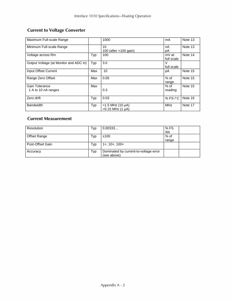
Interface 1010 Specifications--Floating Operation
Appendix A - 2
Current to Voltage Converter
Maximum Full-scale Range 1000 mA Note 13
Minimum Full-scale Range 10 100 (after ×100 gain)
nA pA
Note 13
Voltage across Rm Typ 100 mV at full scale
Note 14
Output Voltage (at Monitor and ADC in) Typ 3.0 V full scale
Input Offset Current Max 10 pA Note 15
Range Zero Offset Max 0.05 % of range
Note 15
Gain Tolerance 1 A to 10 nA ranges
Max 0.3
% of reading
Note 15
Zero drift Typ 0.03 % FS /C Note 16
Bandwidth Typ >1.5 MHz (10 µA) >0.15 MHz (1 µA)
MHz Note 17
Current Measurement
Resolution Typ 0.00333… % FS /bit
Offset Range Typ ±100 % of range
Post-Offset Gain Typ 1×, 10×, 100×
Accuracy Typ Dominated by current-to-voltage error (see above)

Interface 1010 Specifications--Floating Operation
Appendix A - 3
Potentiostatic Mode
Applied Voltage Range Max ±12 volts
Accuracy DC zero offset Gain
Max 1 0.2
mV % setting
Note 18
DC Bias Typ ±8 volts
Scan DAC ranges Typ ±6.4, ±1.6, ±0.4 volts
Drift Max <20 µV/C Note 19
Noise and Ripple 1 Hz to 1 kHz 1 Hz to 200 kHz
Typ 10 20
µV rms Note 20
Galvanostatic Mode
Maximum Full-scale Current ±1000 mA
Minimum Full-scale Current 10 nA
Accuracy Dominated by current to voltage converter accuracy shown above
Sig Gen Voltage for Full-scale Current ±3.0 V
Environmental
Operating Temperature Range 0 to 45 C
Relative Humidity Max 90 (non-condensing) %
Storage and Shipping Temperature –25 to 75 C
Maximum Shipping Acceleration 30 G

Interface 1010 Specifications--Floating Operation
Appendix A - 4
General
Power Input Voltage Range 46 to 50 volts
Power Max 75 W
Leakage Current (Floating, Earthed Working Electrode)
±1 nA Note 22
Dimensions 24 × 27 × 6 cm Note 23
Weight Max 2.0 kg Note 23
Dimensions of External Power Adapter Max 13 × 6 × 3 cm Note 24
Weight of External Power Adapter Max 300 grams Note 24
NOTES:
1. Measured in galvanostatic mode with a high-power 200 Ω load connected from counter electrode lead
to the working electrode lead. The compliance voltage is measured using an external voltmeter across
the 200 Ω load. Under these conditions, the output current is approximately 115 mA.
2. Measured with a precision 4-terminal 2 Ω load, in potentiostatic mode.
3. Unity-gain bandwidth and slew rate are correlated. Each has five settings, with the highest slew rate
occurring at the highest bandwidth, down to the lowest slew rate occurring at lowest bandwidth. Both
are measured with 20 kΩ between counter and reference, and 100 Ω between the reference and the
working and working sense leads.
4. Measured with an external function generator connected to the Ext Sig In BNC.
5. The A/D and signal-processing chain in the Interface 1010 allows measurement of voltage signals as
large as ±13.107 V. The voltage on the working sense lead can be as high as ±0.4 V when measuring
1 A using a 60 cm cell cable. This implies a maximum voltage input on the differential electrometer of
±13.6 V.
In practice, the operational amplifiers in the voltage-signal processing circuitry cannot guarantee
voltages beyond ±12.5 V.
6. This specification is tested using a 2 GΩ resistor switched into the input and measuring the voltage
difference with and without the input resistance.
7. The differential impedance is measured between the reference and working sense inputs. This is the
impedance you measure when you record the EIS spectrum of an infinite impedance (open-lead) cell.
There is also a common-mode resistance and capacitance associated with the differential electrometer
inputs. These values tell you how much the electrometer response is modified by a resistance in series
with the source.
8. The bandwidth is for a sine-wave source with a 50 Ω output impedance driving either input. The
bandwidth is well in excess of this specification, which is limited by the measurement equipment used
in routine testing of the Interface 1010.
9. CMRR is common-mode rejection ratio. It specifies the ability of the differential electrometer to reject
signals connected to both inputs. The CMRR is measured driving both inputs with a sine-wave source
with a 50 Ω output impedance, and measuring the error as a function of frequency. Resistance in
either input causes a loss of CMRR.
10. Voltage measurement is performed with a nominal 3 V signal input to the ADC signal chain. The
actual full scale is 3.2768 V. A 4 attenuator divides down higher-voltage electrometer outputs so they
fit into a 3 V input, thus making a 12 V nominal (13.1072 V) actual full-scale range.

Interface 1010 Specifications--Floating Operation
Appendix A - 5
11. The total error in a voltage measurement is:
Error = Zero Offset Error + Gain Error × Voltage
For a 1 V signal, the theoretical error can be as high as 3 mV. This error is typically less than 0.5 mV.
12. Offsets are summed into the signal. Offset inaccuracy is approximately ±0.05% of the setting plus
±0.5 mV.
13. There are nine hardware current ranges, separated in sensitivity by decades. The ranges are 10 nA, 100
nA, 1 µA, … 100 mA, 1 A full-scale. The ×10 and ×100 gains add two virtual ranges of 1 nA and 100
pA full-scale.
14. The voltage across the current-measurement resistor, Rm, is as shown. On ranges below 1 mA, the
working-electrode voltage is similar to the voltage across Rm. At 1 A and 1 MHz, the working electrode
voltage can be as high as 0.4 V, because the cable has both resistive and inductive impedance.
15. The total error in a current measurement is:
Error = Input Current Offset + Range Zero Offset × FS Current + Gain Tolerance × Measured Current
For small currents (pA) the first term is usually dominant.
For large currents (uA), the first term can usually be ignored.
The units for the error are amperes.
16. Drift can be approximated by simple drift in the Range Zero Error. In reality all three terms in the
equation above can have drift.
17. The Current-to-Voltage converter bandwidth is a function of the current range, the cell cable, and the
IEStability setting. The bandwidth can be very low on very sensitive ranges. Longer cell cables add
capacitance and slow the current measurement.
18. The total error in a voltage setting is:
Error = DC Zero Offset + Gain × Voltage Setting
For a 1 V signal the theoretical error can be as high as 3 mV. In practice the error is generally less than
1 mV.
19. This specification is guaranteed by design. It is not tested.
20. This specification is measured by applying zero voltage across a 1 Ω resistor and measuring current
noise on the 600 µA scale. One µV of voltage noise creates a current of 1 µA. The filters in the ADC
Chain for the I Signal are used to limit the bandwidths as shown in the specification.
Signal-averaging via Gamry DSP mode further reduces the measured noise.
21. See Appendix D.
22. Isolation quality has both DC factors and AC factors (predominately at the 600 kHz power-supply
frequency). Only the DC leakage current is shown here. Consult Gamry technical support for additional
information.
23. Excluding external power adapter and any cables supplied with unit.
24. Excluding removable line cord.

Interface 1010 Specifications--Floating Operation
Appendix A - 6

Interface 1010 Cell Connector--Floating Operation
Appendix B - 1
Appendix B: Interface 1010 Cell Connector
Chapter Error! Reference source not found. describes the connections between a cell cable and an
electrochemical cell. This appendix describes the other end of the cell cable.
Multiple pins assigned to the same signal are connected together on the Interface 1010’s Potentiostat
board. If you need to connect this signal outside the Interface 1010, you need a wire connected to any one
of the D-connector pins.
Table B-1
Cell Connector
Pin(s) Signal Name Use
1 Working Sense Connected to the working electrode in most cases (see Chapter Error!
Reference source not found.). This lead has a 261 Ω resistor in the cell end
of the cable. Custom cell cables are likely to require a similar resistor.
2, 14 WS Shield The shield for the working-sense input. Driven to the same potential as Pin 1.
Left open at the cell end of the cell cable.
3, 4, 15, 17 Reference
Shield
The shield for the reference electrode input. Driven to the same potential as
Pin 16. Left open at the cell end of the cell cable.
5, 7, 10, 11,
18, 19, 22,
24
Ground The potentiostat’s floating ground. Can be used to shield the cell if very low
currents need to be measured. Also used as a shield for the counter electrode
cable.
6 Counter Sense With an Interface 1010, used to sense the potential of the counter electrode.
Allows accurate ZRA mode even with significant cell current through counter
lead’s resistance.
8 CBL_ID1 One of four cable-ID bits. Used to identify the type of cell cable attached to
the unit. Pull to a logic High through a resistor. Ground to set the bit low.
9 CBL_ID2 One of four cable-ID bits. Used to identify the type of cell cable attached to
the unit. Pull to a logic High through a resistor. Ground to set the bit low.
12, 25 Working
Shield
The shield for the working electrode input. Connected to Floating Ground.
Left open at the cell end of the cell cable.
13 Working
Electrode
Connected to the working electrode. The cell current flows through this pin.
16 Reference
Electrode
Connected to the reference electrode in most cases (see Chapter Error!
Reference source not found.). This lead has a 261 Ω resistor in the cell end
of the cable. Custom cell cables are likely to require a similar resistor.
20 CBL_ID0 One of four cable-ID bits. Used to identify the type of cell cable attached to
the unit. Pull to a logic High through a resistor. Ground to set the bit low.
21 CBL_ID3 One of four cable-ID bits. Used to identify the type of cell cable attached to
the unit. Pull to a logic High through a resistor. Ground to set the bit low.
23 Counter
Electrode
Connected to the cell’s counter electrode. The cell current flows through this
connection.
Designing cell cables for a 1 MHz potentiostat is not a trivial task. Gamry Instruments does not
recommend user-designed cables (except as a last resort). In many cases we can build a custom cable to
meet your specific needs. We’ll also be happy to discuss your cable requirements and give you assistance if
you must design and build your own cell cable.

Interface 1010 Cell Connector--Floating Operation
Appendix B - 2

I/O Connectors--User I/O Connector
Appendix C - 1
Appendix C: I/O Connectors
The Interface 1010 includes several I/O connectors other than the Cell Connector described in Appendix B. The
details of these connectors are described here.
User I/O Connector
This connector contains a number of signals used to interface the Interface 1010 to external apparatus. It is the
miniature 15-pin female D-shaped connector on the rear panel of the Interface 1010.
The pin out of this connector is shown in Table C-1.
Table C-1
User I/O Connector
Pin Name Use
1 Analog Output High The auxiliary output signal (DAC output)
2 Analog Output Low The auxiliary output ground connection (ground)
6 Ground Digital ground
7 Digital Out 0 A CMOS-compatible digital output; connecting device input
current must be below 10 µA
8 Digital Out 1 A CMOS-compatible digital output; connecting device input
current must be below 10 µA
9 Digital Out 2 A CMOS-compatible digital output; connecting device input
current must be below 10 µA
10 Digital Out 3 A CMOS-compatible digital output; connecting device input
current must be below 10 µA
11 Digital In 0 A CMOS-compatible digital input; 2.2 kΩ input impedance
12 Digital In 1 A CMOS-compatible digital input; 2.2 kΩ input impedance
13 Digital In 2 A CMOS-compatible digital input; 2.2 kΩ input impedance
14 Digital In 3 A CMOS-compatible digital input; 2.2 kΩ input impedance
15 +5 V Power; 50 mA maximum current
Caution: Floating operation of the Interface 1010 can be compromised by improper cables
to the User I/O connector. We do not recommend use of standard 15-pin shielded cables with this
connector. Custom cables with the shield connected to pin 6 of the D-connector are preferred.
Caution: The ground pin (pin 6) on this connector is earth ground and the D-connector
shell is the Interface 1010 Floating Ground. Improper User I/O connections can damage an Interface 1010
that is connected to a high-energy cell containing earth-grounded terminals.

I/O Connectors--Sync Port
Appendix C - 2
Sync Port
The Sync Port is used to interconnect Interface 1010s that must be operated synchronously: with a single clock
and with simultaneous data acquisition. The sync connector is a 8-pin mini-DIN connector on the rear panel of
the Interface 1010.
Gamry’s synchronization system uses the terms Master and Serf as defined below.
Master: The Master potentiostat provides the clock signal used for all potentiostats and provides data
acquisition pulses used to control the timing of A/D conversion. All synchronous multiple potentiostat systems
have only one Master.
Serf: A Serf potentiostat gets its timing information from a Master potentiostat. A multiple potentiostat system
can have up to seven Serf potentiostats all controlled by one Master.
A special cable is used to connect the instruments that are synchronized. The cable has a Master connector on
one end and a variable number of Serf connectors.
Gamry sells three standard Master-Serf cables:
• 985-00132 One Master and One Serf
• 985-00133 One Master and up to Three Serfs
• 985-00134 One Master and up to Seven Serfs
All of these cables have the Master end of the cable identified by a large M on the DIN connector. Note that a
cable can be used with some instruments missing, so the eight instrument Master-Serf cable can be used for
one Serf, two Serfs, three Serfs,..., seven Serfs.
The Master-Serf connection scheme sends a 24 MHz complex clock signal from the Master to the Serfs using a
daisy-chained low-voltage differential signal (LVDS). Data-acquisition pulses are embedded in the clock signal.
DC pins in the DIN connector are used to detect all cable connections, and, most importantly, detect the
Master end of the cable.
We recommend that you always plug the Master and last Serf ends of the cable into a
potentiostat. You may leave the DIN connectors in the middle of the cable disconnected.
Use only Gamry-supplied cables for all Master-Serf synchronized systems. The cable uses a
differential pair that requires controlled impedance, making user-construction of a cable very difficult.

I/O Connectors--Monitor Connector
Appendix C - 3
Monitor Connector
The Monitor connector is located on the Interface 1010 Front Panel. It is an 9-pin round mini-DIN connector.
One possible mating connector is from CUI Inc. part number MD-80. The pin-out signals of the Monitor
Connector are provided in Table C-2.
Table C-2
Monitor Connector
Pin Name Use
1 Signal Ground A high-quality floating ground. Signals are relative to this ground
2 Signal Ground Another high-quality floating ground. Signals are relative to this
ground
3 RTD Positive The Positive RTD Input. 1 mA flows between this pin and Pin 4.
4 RTD Negative The Negative RTD input. Connected to the Interface 1010’s floating
ground.
5 E_sig E Monitor Signal, ±6.5536 V full scale
6 EXT_SIG External Signal In, ±6.5536 V full scale
7 I_Sig I_Monitor Signal, ±3.2678 V full scale
8 [not connected]
9 [not connected]
I Monitor Signal
The I Monitor signal represents the output of the Interface 1010 current measurement circuit. It can be treated
as a two-wire differential signal with the negative side connected to the Interface 1010 Signal Ground. With the
exception of the filtering described below, it is the raw signal with no offset or gain applied. The effective
bandwidth of the current signal falls as you reach the nA and pA current ranges. IE Stability capacitors further
slow the response.
Scaling on this signal is 3 V for the nominal full-scale current on the selected current range. Cathodic
currents cause a positive output voltage. If the software is auto-ranging the current-range selection, this signal is
discontinuous at each range change.
The I Monitor signal is filtered using an RLC circuit. It has a bandwidth of approximately 150 kHz when
connected to a high-impedance input. This bandwidth is further reduced if a coaxial cable is connected to the
BNC. Its output impedance is approximately 1 kΩ in parallel with 47 pF.
E Monitor Signal
The E Monitor signal is derived from the output of the Interface 1010’s differential electrometer circuit. It can
be treated as a two-wire differential signal with the negative side connected to the Interface 1010 Signal
Ground. With the exception of the filtering described below, it is the raw voltage signal, with no offset or gain
applied. With the exception of the filtering described below, it is buffered representation of the voltage
difference between the white and blue cell cable leads.
Caution: The ground side of the I Monitor signal is connected to the Interface 1010
Floating Ground. Connection signal to an earth-ground-referenced apparatus can compromise the Interface
1010’s ability to float, and invalidate data collected on earth-grounded cells.

I/O Connectors--Monitor Connector
Appendix C - 4
The E Monitor signal is filtered using an RLC circuit. It has a bandwidth of approximately 150 kHz when
connected to a high-impedance input. This bandwidth will be further reduced if a coaxial cable is connected to
the BNC. Its output impedance is approximately 1 kΩ in parallel with 47 pF.
Temperature Monitor Signal
The Interface 1010 offers temperature testing in the range of –50 to 600°C. A 1000 Ω (at 0°C) platinum RTD
(resistance temperature detector) according to European standard (DIN/IEC 60751 or simply IEC751) is used for
the temperature measurement. The RTD sensor contains a resistor that changes resistance as its temperature
changes. The RTD is excited with a precision 1 mA current source. The A/D normally reads 1.000 V when the
RTD is at 0°C, and its resistance change is 3.85 Ω/°C for the temperature range 0 to 100°C. Platinum RTD
elements are available in two types of constructions: thin-film and wire-wound. Platinum RTDs offer several
advantages:
• A wide temperature range (–50 to 500°C for thin-film, and –200 to 850°C for wire-wound)
• Good accuracy (better than thermocouples)
• Good interchangeability
• Not affected by corrosion or oxidation, and
• Long-term stability.
The RTD resistance is read using a two-terminal connection. The RTD is wired between Pins 3 and 4 of the
Monitor Connector. A current source applies 1 mA between these pins. A ∑∆ A/D converter continuously reads
the voltage-difference between the pins.
External Signal In
External Signal In allows you to add a voltage to the Interface 1010’s Signal Generator. It is a two-wire
differential signal with the negative side connected to the Interface 1010 floating ground. This signal is summed
with the other signal-generator sources, including the Bias DAC, the Scan DAC, and the DDS output.
Gamry will not calibrate an RTD you use. If you require higher accuracy for the temperature
reading, you must perform an RTD calibration. Any manufacturer of the RTDs can perform such service. As
an alternative, you may buy a more accurate RTD sensor, such as Class A, AA or 1/10DIN (temperature
range permitted).
Caution: The negative side of the External Signal In signal is connected to the Interface
1010 Floating Ground. Connection of signal to an earth-ground-referenced apparatus can compromise the
Interface 1010’s ability to float, and invalidate data collected on earth-grounded cells.
Caution: The negative side of the E Monitor signal is connected to the Interface 1010
Floating Ground. Connection of signal to an earth-ground-referenced apparatus can compromise the
Interface 1010’s ability to float, and invalidate data collected on earth-grounded cells.

I/O Connectors--Monitor Connector
Appendix C - 5
The signal generator output is directly connected to the potentiostat’s input. When the cell is turned on in
potentiostat mode, the feedback is such that a negative signal-generator output creates a positive differential
electrometer signal, which corresponds to a negative working electrode versus reference electrode voltage.
The polarity of the External Signal In signal is inverted at the signal generator’s output. As described above, a
negative input signal on this input will create a positive change in the working electrode versus reference
electrode voltage. The input impedance of this signal is 2 kΩ.

I/O Connectors--Monitor Connector
Appendix C - 6

Power LED Blink Codes
Appendix D - 1
Appendix D: Power LED Blink Codes
In the rare event that some electronics module fails, we include the start-up blink codes that the blue Power
LED flashes. Upon start-up, view the Power LED. If it blinks more than five times, or flashes one of the blink-
codes below, please call Gamry Instruments for service.
Normal Start-up
The Power LED flashes three times.
Failure in an electronics module
The Power LED flashes codes depending upon the failed module:
Problem Power LED blink code
Post SDRAM unidentified problem Twice, then once
Post SDRAM size error Twice, then twice
Post ROM checksum error Twice, then three times
Post Serial init. RX buffer Three times, then four times
Post Serial init. TX buffer Three times, then five times
Post Serial init. UART Three times, then six times
Post Communications module missing Three times, then eight times
Post Control missing Four times, then once
Post potentiostat missing Four times, then twice
If there are multiple problems, the communications board takes code priority over the memory module.
Severe problem
The red LED, which normally switches off after a rapid boot-up, remains illuminated.
Error Messages and Limitations
The Interface 1010 has a subtype, Interface 1010T, which may generate error messages under certain run-time
conditions:
Error Message This instrument is not authorized for Freq=
The Interface 1010T is able to perform EIS at frequencies 20 kHz or lower. Higher frequencies generate this
error message. Decrease the upper frequency to continue.
Error Message This instrument is not authorized for IERange=
The Interface 1010T is able to operate at currents of 100 mA or lower. Higher currents generate this error
message. Decrease the current to continue.
Error Message This instrument is not authorized for ScanRate=
The Interface 1010T is able to scan at rates of 1 V/s or lower. Higher scan rates generate this error message.
Decrease the scan rate to continue.
If you receive one of the above codes, please call Gamry Instruments Service Department for
assistance.

Power LED Blink Codes
Appendix D - 2
Error Message This instrument is not authorized for SampleTime=
The Interface 1010T is able to record data with a sample time of 1 ms or higher. Shorter sample times generate
this error message. Increase the sample time to continue.

CE Certificate
Appendix E - 1
Appendix E: CE Certificate

CE Certificate
Appendix E - 2
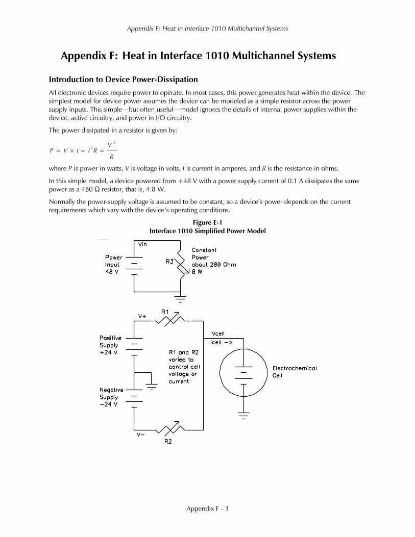
Appendix F: Heat in Interface 1010 Multichannel Systems
Appendix F - 1
Appendix F: Heat in Interface 1010 Multichannel Systems
Introduction to Device Power-Dissipation
All electronic devices require power to operate. In most cases, this power generates heat within the device. The
simplest model for device power assumes the device can be modeled as a simple resistor across the power
supply inputs. This simple—but often useful—model ignores the details of internal power supplies within the
device, active circuitry, and power in I/O circuitry.
The power dissipated in a resistor is given by:
R
V
RIIVP
2
2
==×=
where P is power in watts, V is voltage in volts, I is current in amperes, and R is the resistance in ohms.
In this simple model, a device powered from +48 V with a power supply current of 0.1 A dissipates the same
power as a 480 Ω resistor, that is, 4.8 W.
Normally the power-supply voltage is assumed to be constant, so a device’s power depends on the current
requirements which vary with the device’s operating conditions.
Figure E-1
Interface 1010 Simplified Power Model

Appendix F: Heat in Interface 1010 Multichannel Systems
Appendix F - 2
Potentiostat/Galvanostat Power Model
A potentiostat requires a somewhat more sophisticated power-dissipation model. A simple potentiostat power
model can be found in Figure E-1. The electrochemical cell has a voltage Vcell that plays a role in the
instrument’s power dissipation.
The variable resistors take different values depending on the potentiostat/galvanostat’s operating conditions. The
upper portion of the model describes a fairly constant power draw in the Interface 1010 circuitry. This power
comes from the normal operation of the instrument: running its microprocessor, powering its operational
amplifiers and D/A and A/D converters, etc. There is some variability in this power depending on signal levels in
the analog circuitry, probably from 6 to 10 W, but we can assume 8 W.
The lower portion of the figure shows the power effects that come from the Interface 1010 power amplifier
polarizing the electrochemical cell. V+ and V− are 24 V power supplies generated within the Interface 1010.
R1 and R2 model the power MOSFET transistors that control current flow through the cell.
When the cell current and cell voltage are both small, R1 and R2 have approximately equal values: about 240
Ω. This creates a steady-state current of about 100 mA through R1 and R2, resulting in “quiescent” power
dissipation of a little less than 5 W.
The values of R1 and R2 change when current flows into or out of the cell. When +1 A flows into a zero-
voltage cell, R1 is around 24 Ω and R2 becomes very large. In this condition, power-amplifier dissipation is 24
W and the total device power is about 32 W.
The Interface 1010’s total power dissipation with the cell polarized is approximated by:
2
+
1
+
3
=
22
+
R
VVcell
R
VcellV
R
Vin
P
With large cell currents, the current from one leg of the circuit dominates power-amplifier dissipation and total
device power becomes:
( )IcellVcellV
R
Vin
P +
3
=+
Or
( )IcellVVcell
R
Vin
P +
3
=
Note that Vcell can be either positive or negative.
Power dissipation within the Interface 1010 raises the temperature within the unit and on the exterior of the
unit. In rare cases, the temperature increase can create an over-temperature event, upon which the unit shuts
off the cell current and enters a protective latch-up state. You can only recover from this state by turning off the
power on the Interface 1010, waiting for the device to cool, and turning the power back on.
Discharging a Battery
The highest power application for a potentiostat is discharging a battery stack (or a stack of other energy storage
devices such as electrical double-layer capacitors or fuel cells). Unlike single cells, stacks can have voltages that
stress the power-dissipation capabilities of a potentiostat. In the calculations that follow, 8 W of load-
independent power dissipation is assumed.
− −
−
−
−
−

Appendix F: Heat in Interface 1010 Multichannel Systems
Appendix F - 3
Let’s look at the power in three typical, high-current battery discharges:
• If we only have a single battery and its voltage is 5 V, the maximum power dissipation is 37 W.
• If the battery stack has a voltage equal to the largest measurable Interface 1010 cell voltage (12 V), the
maximum power dissipation in the instrument is 44 W.
• In an unusual experiment, a resistive voltage divider on the voltage measurement could allow Interface
1010 operation with battery stacks with voltages as high as 20 V. In this case, the maximum total power
dissipation is 52 W.
The maximum power drawn from the instrument’s power input jack is largely independent of the cell voltage.
The maximum is 32 W (divided by the power supply’s efficiency). The higher power levels mentioned above
occur because the battery is sourcing power.
Single Interface 1010
Gamry has tested a single Interface 1010 operating at its most extreme condition: discharge of a 20 V cell at 1 A
current. The unit was run in its normal horizontal position, with 1 A cell current and a 20 V cell voltage. The air-
flow though the unit was unimpeded.
In this test, the unit could be operated indefinitely, with no over-temperature events seen, even with a 45°C
ambient temperature. The highest temperature measured on the outside of the Interface 1010 chassis was 15°C
above ambient.
Vertical Stacks
Gamry also tested a system with four Interface 1010s stacked one atop another (a vertical stack of horizontal
units). In this configuration, the Interface 1010s ran hotter, because power dissipation in one unit can radiate
heat to adjacent units and also preheat the air used to cool other units. The units higher in the stack ran hotter
because their cooling air was preheated by the units below them. The cooling air entering the unit on the
bottom of the stack was unheated, so this unit ran significantly cooler than all the others.
We saw over-temperature events in this configuration when the units were operated at the unusual condition of
discharging a 20 V battery. The over-temperature events occurred on upper units and only occurred after at
least 20 minutes of continuous worst-case power operation. The case of the hottest Interface 1010 was also
more than 25°C above ambient.
The system operated indefinitely with no problems when the cell voltage was limited to 12 V or less. The
highest temperature measured on the outside of hottest Interface 1010 chassis was 20°C above ambient.
Interface Power Hub Systems
The Interface Power Hub uses forced-air cooling to lower temperatures in stacked Interface 1010s. The units
are turned 90° to run in an array of vertical instruments.
Gamry tested a system with eight Interface 1010s mounted in an Interface Power Hub. All units were operated
at the worst-case condition of 52 W power dissipation: discharge of a 20 V cell at 1 A.
In this test, the system could be operated indefinitely with no over-temperature events seen, even with a 45°C
ambient temperature. The top of the Interface Power Hub chassis got warm, but stayed at less than 15°C above
ambient.

Appendix F: Heat in Interface 1010 Multichannel Systems
Appendix F - 4

Appendix G: Capabilities of Various Models of Interface 1010
Appendix G - 1
Appendix G: Capabilities of Various Models of Interface 1010
Below is a table of the various types of Interface 1010 potentiostats, and their respective capabilities.
Function
Interface
1010T
Interface
1010B
Interface
1010E
Electrochemical Impedance Spectroscopy
Potentiostatic Impedance Spectroscopy * *
Potentiostatic EIS Repeating * *
Galvanostatic Impedance Spectroscopy
Hybrid Impedance Spectroscopy
Single Frequency Impedance Spectroscopy * *
Mott-Schottky * *
OptiEIS Multisine Potentiostatic Impedance
Spectroscopy
OptiEIS Multisine Galvanostatic Impedance
Spectroscopy
DC Corrosion Techniques
Corrosion Potential
Linear Polarization Resistance
Tafel scan
Potentiodynamic scan
Cyclic Polarization
Electrochemical Reactivation
Galvanic corrosion
Galvanodynamic
Cyclic Galvanodynamic
Galvanostatic
Potentiostatic
THE Repassivation Potential
Critical Pitting Potential
Critical Pitting Temperature
Cyclic Thermammetry
Rp/Ec Trend
Electrochemical Noise (including Electrochemical
Signal Analyzer)
Physical Electrochemistry
Cyclic Voltammetry
Linear Sweep Voltammetry
Chronopotentiometry
Chronocoulometry
Chronoamperometry
Repeating Chronoamperometry

Appendix G: Capabilities of Various Models of Interface 1010
Appendix G - 2
Repeating Chronopotentiometry
Controlled Potential Coulometry (Bulk
Electrolysis)
Multiple-Step Chronoamperometry
Multiple-Step Chronopotentiometry
AC Voltammetry
Pulse Voltammetry
Differential Pulse Voltammetry
Normal Pulse Voltammetry
Reverse Normal Pulse Voltammetry
Differential Pulse Stripping Voltammetry
Square Wave Voltammetry
Square Wave Stripping Voltammetry
Normal Pulse Stripping Voltammetry
Reverse Normal Pulse Stripping Voltammetry
Potentiostatic Generic Pulse
Galvanostatic Generic Pulse
Sample DC Voltammetry
Electrochemical Frequency Modulation (EFM)
EFM
EFM Trend
Electrochemical Energy
Cyclic Charge Discharge
Charge
Discharge
Polarization Curve
Galvanostatic
Potentiostatic
Cyclic Voltammetry
Leakage Current
Read Voltage
Self-Discharge
Potentiostatic Intermittent Titration Technique
Galvanostatic Intermittent Titration Technique
eChem Toolkits
Virtual Front Panel
eChemBasic
eChemDC
eChemAC
*Maximum frequency = 20 kHz

Index
Index - 1
Appendix H: Index
25 pin D, 3-6
AC adapter, 1-1
ADC channels, 7-4
air-cooling, 1-3
alligator clip, 5-2
ancillary apparatus, 9-7
auxiliary electrode, 5-1
black banana, 5-1
blink codes, 3-4, 9-1
Blink Codes, 9-1
blue cell lead, 5-1
Cable calibration, 4-1
Calibrate in Framework button, 4-1
calibration, 4-1, 4-2
calibration data, 7-5
capacitive cells, 8-1
CE Compliance, 1-6
cell cable, 5-1
replacements and specials, 5-2
ZRA connections, 5-2
Cell Connector, 3-6, 6-2, 9-1
cell construction materials, 9-6
Cell On LED, 6-3, 6-4
Chassis Ground, 6-6
cleaning, 1-4
computer, 2-2
computer requirements, 3-2
computers - noise, 9-5
contract engineering, ii
Control Overload, 6-4
conventions
notational, 2-3
Counter Electrode, 5-1, 9-1
Counter Sense, 9-1
data storage, 7-5
DC and AC calibration, 4-1
DC voltage, 7-6
DDS, 7-3
Device Status Bar, 3-7
double insulation, 1-1
E Monitor signal, 9-3, 9-4
E Overload, 6-4
earth ground, 1-2, 9-5, 9-7
EIS speed, 9-6
electrical noise, 9-5
electrical transients, 1-5
electrons per second, 9-1
enclosed space, 1-4
environmental limits, 1-4
environmental stress, 1-4
Experiment drop-down menu, 4-1
External Signal In, 9-3, 9-4, 9-5
fan speed, 1-3
Faraday shield, 5-2, 9-5
filters, 7-4
firmware download, 6-3
firmware update, 3-9
Floating Ground, 5-1, 6-6
floating ground binding post, 1-2
floating operation, 9-7
fluorescent lights, 9-5
Framework software, 3-7, 3-11
Gamry Framework, 2-1
green cell lead, 5-1
ground, 9-1
Help system, 2-1
high frequency shunt, 8-3
high speed USB, 6-6
horizontal stack, 9-3
I Monitor signal, 9-3
I Overload, 6-4
input capacitance, 9-1
input current, 9-1
input impedance, 9-1
input leakage current, 9-3
inspection, 1-1
installation, 3-1
Instrument Manager, 3-8
Interface 5000E, 3-9
Interface Power Hub, 2-2, 9-3
Johnson noise, 9-2
lead capacitance, 9-6
lead placement, 9-5
Luggin capillaries, 8-2, 9-6
Master, 9-2
materials, 9-6
measurement system model, 9-1
membrane cell connections, 5-3
Monitor Connector, 1-3, 6-2, 9-3, 9-4

Index
Index - 2
motors, 9-5
multichannel, 2-2, 2-3
noise, 9-4
operation, 1-4
Options menu, 3-7, 3-8
orange lead, 5-1
oscillation, 8-1
Overload LED, 6-4
over-temperature event, 9-2
overview, 2-1
personalization label, 3-9
power brick, 1-1
Power Connection, 3-3
Power Cord, 3-3
Power Dissipation, 9-1
Power In jack, 6-5
power line transient, 1-5
Power PC, 7-5
Power switch, 3-4, 6-1
PWR LED, 3-4, 6-1, 6-2, 9-1
radio frequency, 1-5
radio transmitters, 9-5
red cell lead, 5-1
Reference Electrode, 5-1, 9-1
reference electrode impedance, 9-6
ringing, 8-1
safety, 1-1
schematic, 7-1
Serf, 9-2
service, 1-5
service contract, ii
shielding against noise, 1-2
small signals, 9-1
software calibration, 1
specifications, 1
stability, 8-1
state-machine, 7-4
static electricity, 1-5
storage, 1-4
support, ii
Sync port, 2-2, 6-7, 9-2
telephone assistance, ii
temperature, 1-3
Temperature Monitor Signal, 9-4
Universal Dummy Cell, 4-2
USB cable, 3-5
USB LED, 3-6, 6-2, 6-3, 6-6
USB port, 6-6
USB Processor, 7-5
User I/O Connector, 1-3, 6-7, 9-1
Visual Inspection, 3-1
voltage noise, 9-4
Warranty, iii
WE Shield, 9-1
white cell lead, 5-1
Working Electrode, 5-1, 9-1
Working Sense, 9-1
WS Shield, 9-1
ZRA
cell connections, 5-2


![Applied electrochemical biosensor based on covalently self ... · PDF fileAuto lab Potentiostat/Galvanostat, ... tremely corrosive and must be handled carefully]) ... Electrochemical](https://img.dokumen.tips/doc/110x75/5abe0b0e7f8b9a5d718c7cf7/applied-electrochemical-biosensor-based-on-covalently-self-lab-potentiostatgalvanostat.jpg)