Embed Size (px)
Citation preview
Copyright Information ©2020-2021 Consolidated Edison Co. of New York, Inc.
Paper copies of procedures and instructions are uncontrolled and therefore may be outdated. Please consult Distribution Engineering Intranet Site Distribution Engineering or http://distribution for the current version prior to use.
Page 1/38
CONSOLIDATED EDISON COMPANY OF NEW YORK, INC. 4 IRVING PLACE
NEW YORK, NY 10003
DISTRIBUTION ENGINEERING DEPARTMENT System Design Section
EO-10215
REVISION 1
Interconnection Requirements For Distributed Energy Resources (DER) To Select High Tension
Non Network Distribution Systems
PREPARED BY:
GOLDMAN, STEVE; WOO, ANDY
TARGET AUDIENCE ENGINEERING AND PLANNING REVIEWED BY: ELECTRIC OPERATIONS; REGIONAL CONTROL
CENTERS; METER & TEST; SI METER SERVICES ELECTRIC METER SHOP; ENERGY SERVICES
CUSTOMER OPERATIONS
NESC REFERENCE Sec. 9, 10, 11, 12, 15, 16, 17, 18, 44 FILING: APPLICANTION AND DESIGN MANUAL No. 4
FIELD MANUAL No. 16, SECTION 4
APPROVER SERGIO RODRIGUEZ SIGNATURE/DATE Signature on File – February 3, 2021
EFFECTIVE DATE: FEBRUARY 3, 2021
Specification Revision Rev Date Effective Date
Copyright Information Page 2/38
EO – 10215 1 Feb.3 2021 02/03/2021 ©2020-2021 Consolidated Edison Co. of New York, Inc. Filing Information Construction Standard Paper copies of procedures and instructions are uncontrolled and therefore may be outdated. Please consult Distribution Engineering Intranet Site Distribution Engineering or http://distribution, for the current version prior to use.
TABLE OF CONTENTS 1.0 PURPOSE ..................................................................................................................... 3 2.0 SCOPE .......................................................................................................................... 3 3.0 APPLICATION .............................................................................................................. 4 4.0 DEFINITIONS ............................................................................................................... 4 5.0 GENERAL ..................................................................................................................... 6 6.0 GENERAL CONSTRUCTION REQUIREMENTS ......................................................... 7 7.0 DETAILED REQUIREMENTS FOR THE HTME .......................................................... 9
FIGURE 1: CONCEPTUAL RADIAL HIGH-TENSION SERVICE 3-LINE & SIMPLE PLAN VIEW ........................................................................................ 16
FIGURE 2: CONCEPTUAL HIGH TENSION METERING ENCLOSURE (HTME) INTERIOR - FRONT VIEW .............................................................................. 17
FIGURE 3: CONCEPTUAL HIGH TENSION METERING ENCLOSURE (HTME) INTERIOR - REAR VIEW ................................................................................ 18
FIGURE 4: CONCEPTUAL HIGH TENSION METERING ENCLOSURE (HTME) ...... 19 LEFT SIDE PROFILE – INTERIOR COMPARTMENTS .............................................. 19 FIGURE 5: CONCEPTUAL HIGH TENSION METERING ENCLOSURE (HTME)
RIGHT SIDE PROFILE – INTERIOR COMPARTMENTS ................................ 20 FIGURE 6: CONCEPTUAL HIGH TENSION METERING ENCLOSURE (HTME)
EXTERIOR FRONT VIEW................................................................................. 21 FIGURE 7: CONCEPTUAL HIGH TENSION METERING ENCLOSURE (HTME)
EXTERIOR REAR VIEW ................................................................................... 22 FIGURE 8: CONCEPTUAL HIGH TENSION METERING ENCLOSURE (HTME)
EXTERIOR LEFT SIDE VIEW........................................................................... 23 FIGURE 9: CONCEPTUAL HIGH TENSION METERING ENCLOSURE (HTME)
EXTERIOR RIGHT SIDE VIEW ........................................................................ 24 FIGURE 10: CONCEPTUAL HIGH TENSION METERING ENCLOSURE
(HTME) TOP VIEW ........................................................................................... 25 8.0 REQUIRED TESTING ................................................................................................... 26 9.0 STANDARD AND CODE REQUIREMENTS ................................................................ 26 10.0 MAINTENANCE AND INSPECTION ............................................................................ 26 11.0 LIST OF COMPANY REFERENCES............................................................................ 27 12.0 PROJECT SCOPE PRELIMINARY CHECKLIST ........................................................ 28 13.0 CUSTOMER AGREEMMENT ....................................................................................... 29 APPENDIX A: REQUIRED DOCUMENTATION ...................................................................... 30 APPENDIX B: DESIGN STANDARDS .................................................................................... 32 APPENDIX C: PROCESS & APPROVAL OF PROJECT DRAWINGS AND
DOCUMENTS ............................................................................................................... 37
Specification Revision Rev Date Effective Date
Copyright Information Page 3/38
EO – 10215 1 Feb.3 2021 02/03/2021 ©2020-2021 Consolidated Edison Co. of New York, Inc. Filing Information Construction Standard Paper copies of procedures and instructions are uncontrolled and therefore may be outdated. Please consult Distribution Engineering Intranet Site Distribution Engineering or http://distribution, for the current version prior to use.
EO-10215: INTERCONNECTION REQUIREMENTS FOR DISTRIBUTED ENERGY RESOURCES (DER) TO SELECT HIGH TENSION NON NETWORK
DISTRIBUTION SYSTEMS 1.0 PURPOSE
This specification provides Consolidated Edison Company's requirements for interconnection to prospective inverter-based Distributed Energy Resources (DER) customers seeking high tension service and interconnection. This means specifically Auto Loop, 4 kV Grid, Step Down Feeder distribution systems and not primary feeders trunk/main lines also known as feeder proper cable sections.
2.0 SCOPE
This type of service, classified as non-standard overhead (non-network distribution) high tension service and interconnection, is available exclusively for inverter-based technology distributed generation (DG) facilities without the expectation of redundant service equipment. Upon the Coordinated Electric System Interconnection Review (CESIR) review, the Company will determine if the customer application qualifies for this type of High Tension radial service and interconnection. The Company will select the appropriate configuration, or may elect to decline to offer this option for interconnection if is not feasible or where it would otherwise negatively impact the Company service or the reliability of existing Customers. There shall be no outside customer electric loads fed from this type of high tension service that are not in direct support of a generation facility. There shall be no electric loads fed from this type of high tension service that are not in direct support of a generation facility; therefore this type of interconnection shall not be required to have a minimum contingency design. The Customer may request additional local alternate supply feeders for greater redundancy. The Customer may also seek multiple iterations of this type of high tension service within one facility utilizing separate radial overhead feeders. Submission and acceptance of the Customer’s DG plant, operating procedures, and open transition methods is required. Depending on the specific request, site, and design, the Customer may be required to file separate interconnection or service applications. This specification includes requirements for interconnection and the High Tension Metering Enclosure (HTME) situated between the overhead Utility feeder and the first high tension disconnect device on the Customer’s side of the meter. This specification does not cover any other customer infrastructure including switchgear, transformers, or DG product that are downstream of the
Specification Revision Rev Date Effective Date
Copyright Information Page 4/38
EO – 10215 1 Feb.3 2021 02/03/2021 ©2020-2021 Consolidated Edison Co. of New York, Inc. Filing Information Construction Standard Paper copies of procedures and instructions are uncontrolled and therefore may be outdated. Please consult Distribution Engineering Intranet Site Distribution Engineering or http://distribution, for the current version prior to use.
first high tension disconnect. Specific requirements associated with the DG installation shall be reviewed during the CESIR study. All equipment including Metering, Telemetry, Monitoring, Control, etc. required for NYISO market participation is not covered in this specification and is the responsibility of the customer to procure and install in addition to the requirements set forth in this document. For traditional high tension service interconnection, refer to EO-2022, “GENERAL SPECIFICATION FOR HIGH TENSION SERVICE.”
3.0 APPLICATION
Distributed Generation customers utilizing inverter base systems targeted to interconnect to Brooklyn, Queens, Bronx, Westchester, Staten Island 4 kV, 13 kV, and 27 kV Auto Loop Distribution Systems; 4 kV Grid Primary Network Feeders; or Stepdown Feeders where sized appropriately
4.0 DEFINITIONS
4.1 Customer and Company - For future reference throughout this specification, the Consolidated Edison Company of New York, Inc. is referred to as the "Company". All reference to "Customer" shall refer to the owner of the DG installation.
4.2 Company Service Type and Voltage - High Tension (HT) Service will be radial. All High Tension Service Customers are provided a primary nominal voltage of; 4 kV, 13 kV, 27 kV or 33 kV. The Con Edison Customer Service Representative will provide the actual service voltage on request.
4.3 Customer Utilization Voltage - The Customer’s utilization voltage is based on the Customer’s distributed generation equipment requirements. The Customer’s responsibility is to install equipment that will properly operate within the range of standard voltage deviations. The Customer’s responsibility includes providing surge suppression and EMI (electromagnetic interference) filtering with their DG equipment. The inverter technology within the generation is expected to react to voltage and frequency deviations as stated in the New York State Interconnection Requirements and additional Company stipulations resulting from the CESIR, if any. Also, the DG’s auxiliary support loads (HVAC, security, SCADA, communications, fire alarm system, etc.) shall be tolerant of momentary line voltage rise, sags, and unbalances.
Specification Revision Rev Date Effective Date
Copyright Information Page 5/38
EO – 10215 1 Feb.3 2021 02/03/2021 ©2020-2021 Consolidated Edison Co. of New York, Inc. Filing Information Construction Standard Paper copies of procedures and instructions are uncontrolled and therefore may be outdated. Please consult Distribution Engineering Intranet Site Distribution Engineering or http://distribution, for the current version prior to use.
4.4 Contingencies – For the purpose of traditional power delivery service, each part of the Company's service territory has been categorized by the number of allowable coincidental feeder outages that can be tolerated without adversely affecting the availability of the Customer's service. These outages are referred to as contingencies. In a first contingency area, the Customer's high tension installation must be designed for the loss of one primary service feeder. In a second contingency area, the Customer's high tension installation must be designed for the loss of two primary service feeders. Therefore, to ensure the Customer's service configuration matches the Company's design criteria, the Customer is provided a minimum of two primary service feeders in a first contingency area and a minimum of three primary service feeders in a second contingency area. During contingency operation, the design (capacity, configuration, relays, transformers, switchgear, etc.) of the Customer’s installation must be such that the Customer’s entire maximum supply/demand can be serviced without overloading Customer or Company equipment and must be in accordance with the electrical codes governing the use of this equipment.
4.4.1 DG-Only/Export Minimum Contingency – For the of DG-Only
service as defined in this specification, there is no minimum contingency design requirement for this type of high tension interconnection regardless of the service region. If the customer does not design for at least first contingency, then there shall not be any customer load associated with the service that cannot tolerate long term feeder outages unless the customer provides their own transfer switchgear to supply the load with a separate utility service or a form of onsite generation.
4.5 Property Line Customer Box – Customer built structure at the customer
property line that demarcates utility and customer change of ownership.
4.6 Point Of Entry (POE) – The agreed upon point of entry of electrical service to the customer’s property via the Property Line box.
4.7 Point of Common Coupling (PCC) - The point of connection between
the Area EPS and the Local EPS. Also defined as the point at which the interconnection between the electric utility and the customer interface occurs. Typically, this is the customer side of the utility revenue meter.
4.8 Vacuum Recloser Switch (VRS) – An isolation and protection device
typically outfitted with SCADA capabilities specifically designed to work on overhead distribution systems.
Specification Revision Rev Date Effective Date
Copyright Information Page 6/38
EO – 10215 1 Feb.3 2021 02/03/2021 ©2020-2021 Consolidated Edison Co. of New York, Inc. Filing Information Construction Standard Paper copies of procedures and instructions are uncontrolled and therefore may be outdated. Please consult Distribution Engineering Intranet Site Distribution Engineering or http://distribution, for the current version prior to use.
4.9 Utility High Tension Service Equipment - Utility equipment required to provide the radial high-tension service for the customer DG facility, consisting of the vacuum recloser switch (VRS), the utility revenue-grade metering equipment (HTME) cables, poles, grounding devices, protection, control and monitoring equipment, auxiliary devices, and associated mounting structures installed and situated between the overhead Utility feeder up to and including the first high tension disconnect device.
4.10 High Tension Metering Enclosure (HTME)– The metal enclosure
housing the Utility service termination point, metering and instrumentation equipment cubicles required for high tension radial service. The Customer shall design, build, and install the HTME in accordance with this specification.
4.11 Coordinated Electric System Interconnection Review (CESIR) - A CESIR is a detailed review and explanation of an interconnection’s impact to the utility system and its compliance with applicable criteria, including protective coordination, fault current, thermal, voltage, power quality, and equipment stress.
5.0 GENERAL
5.1 Items for Review - Customer shall furnish all electrical and site drawings,
diagrams, specifications and Bill of Materials for the complete electrical service installation. This shall include, but not be limited to; manholes, feeder cables, splices, fused load-break switches, draw-out circuit breakers, power and instrument transformers, disconnects, ground and transfer switches, buses, power transformer vaults, oil containment systems, site plans and duct layouts, vault/electrical room layouts, etc.
5.2 Review Process - During the design process of the High Tension
Metering Enclosure (HTME) and the Utility High Tension Service Equipment shall submit their design documents with product information for Company review and acceptance.
5.3 Service Availability - Recommendations and requirements outlined in the
Company specifications and/or project documents shall apply to the specific location, auxiliary load, and generation. At other locations or for other auxiliary load and generation requirements, a service with similar characteristics may not be available and different requirements may be imposed.
5.4 New York State Standardized Interconnection Requirements –
Published by the New York State Public Service Commission. Referred to
Specification Revision Rev Date Effective Date
Copyright Information Page 7/38
EO – 10215 1 Feb.3 2021 02/03/2021 ©2020-2021 Consolidated Edison Co. of New York, Inc. Filing Information Construction Standard Paper copies of procedures and instructions are uncontrolled and therefore may be outdated. Please consult Distribution Engineering Intranet Site Distribution Engineering or http://distribution, for the current version prior to use.
herein as the SIR. The revision in effect at the time of the Customer’s application for interconnection shall apply to the Company’s CESIR if the total paralleled DG is within the megawatt range applicable to the SIR. For DG request that exceed the SIR limit, a separate Non-SIR process applies. Contact the Con Edison’s ESD department for additional information.
5.5 Site Inspections - During the construction and installation process,
Company representatives will visit to inspect the site. These visits will be scheduled as milestones dictate (e.g., foundation construction with grounding conductor, entry and exit feeder duct installation, metering transformer wiring, etc.).
6.0 GENERAL CONSTRUCTION REQUIREMENTS
6.1 Service extension into customer property – Refer to
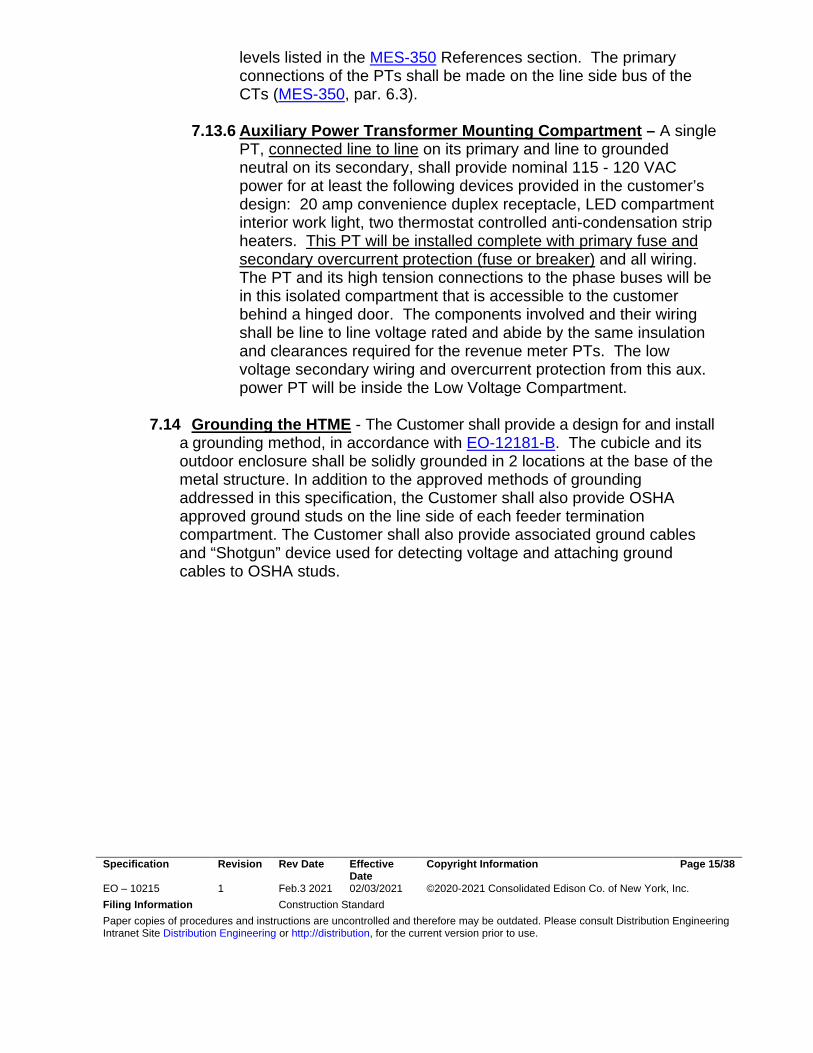
“FIGURE 1: CONCEPTUAL RADIAL HIGH-TENSION SERVICE” Three Line Diagram. This sketch is provided for guidance only. The customer shall provide a detailed set of site-specific drawings.
6.2 Service construction- The Company will extend high tension service into
the Customer’s property at the expense of the Customer. The service determination process will provide the Customer a VRS/POE utility pole to the customer property line in accordance with applicable Company and tariff rules. On top of this pole will be a vacuum recloser switch (VRS). The utility pole and VRS will be provided and installed by the Company and shall be simply referred to as “the Utility VRS/POE pole.” Please note, the Utility VRS and POE pole may be the same physical pole or multiple poles depending on system conditions. The Company will determine the appropriate configuration or may decline to offer this type of interconnection altogether where it is not physically feasible or where it would otherwise negatively impact the Company, Service, or its existing Customers. The VRS device shall be equipped with visible break switches (one per phase), which are in series with the non-visible contacts within the vacuum bottles.
6.3 Customer Property Line Box within 25 feet of the Utility VRS/POE
pole - The Company will construct the riser conduit attached to the Utility VRS/POE pole. The Company will supply and pull the conductor service cable between the VRS/POE pole and the customer property line box. The Customer is responsible for the property line box and all construction beyond this point including but not limited to the HTME, splicing, terminations, underground concrete encased duct bank(s), all trench work,
Specification Revision Rev Date Effective Date
Copyright Information Page 8/38
EO – 10215 1 Feb.3 2021 02/03/2021 ©2020-2021 Consolidated Edison Co. of New York, Inc. Filing Information Construction Standard Paper copies of procedures and instructions are uncontrolled and therefore may be outdated. Please consult Distribution Engineering Intranet Site Distribution Engineering or http://distribution, for the current version prior to use.
all materials and equipment. The Customer shall continue the concrete encased duct bank from this property line box to the service termination compartment at the HTME location. The exact location of the customer line property box, which is to be located within 25 feet from the VRS/POE pole location must be indicated on a submitted site plan with surveyed distances. The Company reserves the right to disapprove the requested HTME location if the Company believes factors exist which could negatively impact safety, service, or reliability (e.g. Distance, Terrain, Accessibility, Etc.). The Customer shall build the customer property line box in accordance with EO-2468-B “Cable Manhole M11-6”. Additionally, the property line box’s entrance shall be flared in accordance to EO-6130-D “Flared Conduit For Primary Cable Manhole Entrance”.
6.4 Limitations – Some municipalities and areas of NYC supplied by Non-
Network distribution systems may no longer allow additional overhead infrastructure. Where such physical limitations exist, the Company may not offer this type of service.
6.5 Additional poles & spans into customer property – The Customer can
install additional Customer owned poles, with or without disconnect switches on them, beyond the service termination compartment at the Revenue Meter. The Customer shall provide the Company with detailed system characteristics to study coordination and protection at the customer’s facility.
6.6 High Tension terminations within the Customer’s property – The
Customer shall submit documentation for Company review and acceptance of HT termination kits. The Company accepted kits shall be supplied by the Customer at all locations inside their property including all feeder termination compartments, and the primary connections at the Utility Revenue Metering transformers. 6.6.1 Wiring and Connections - The Customer shall furnish, install and
maintain all mounting facilities, wiring and conduit for connection of the Company’s revenue metering instrument transformers to the metering devices for the initial installation and any subsequent alterations. Final connection to the meters from the associated instrument transformers will be made by the Company. The Customer shall make the primary connection to the metering instrument transformers. The Customer shall allow Company access for meter reading, testing and maintenance without prior notification.
Specification Revision Rev Date Effective Date
Copyright Information Page 9/38
EO – 10215 1 Feb.3 2021 02/03/2021 ©2020-2021 Consolidated Edison Co. of New York, Inc. Filing Information Construction Standard Paper copies of procedures and instructions are uncontrolled and therefore may be outdated. Please consult Distribution Engineering Intranet Site Distribution Engineering or http://distribution, for the current version prior to use.
6.7 Customer Distributed Generation Plant - The Customer shall submit all required documentation for Company review and acceptance in accordance with the SIR. and shall be equipped with locks and accessible only to qualified personnel. Doors shall be equipped with a quick release mechanism with a full width actuator (i.e., panic bar) on the inside of the door and shall be capable of opening the door from the inside even if locked. Customer transformer vaults, transformer rooms, equipment and switchgear equipment areas shall be free of debris and shall incorporate Company safety design standards.
6.8 Multiple services- Multiple HTME services shall be spaced at least ten
(10) feet apart.
7.0 DETAILED REQUIREMENTS FOR THE HTME 7.1 Design and Construction responsibility - The Customer shall design,
build, and install a metal enclosure with multiple hinged door accessible isolated compartments designated as the Utility “High Tension Metering Enclosure (HTME).” The design shall meet the requirements of this specification, referenced specifications, and be subject to review and approval. It will also need to be inspected by the Company in advance of energization and scheduling the Company’s field service groups for feeder splicing, duct inspection, and revenue meter installation.
7.2 Purpose – The purpose of the HTME is to provide a detached stand-
alone structure to contain the HT service meter, instrument transformers (CTs & PTs), data acquisition equipment, wireless technology, and transition points between Utility service cable and bus (i.e, terminations). All the components of the cubicle are only associated with the Company’s revenue metering of a single Utility high tension service connected to a single Utility feeder. There shall be no circuit breakers, phasing receptacles, protective relays, control circuits, or equipment used for other meters in this facility. The individual compartments’ design, dimensions, clearances, and selected internal equipment shall be determined by Company specification MES-350, High Tension Metering Installations General Requirements, latest revision. If there are discrepancies between statements made anywhere in this specification compared to what is stated in MES-350 about the same subject, then MES-350 shall take precedence.
7.3 HTME Location - The Utility high tension service essentially runs through this facility as it is physically located between the Utility VRS/POE pole and the Customer’s first HT disconnect device. This HTME shall be located within Customer property and its exact location indicated on a
Specification Revision Rev Date Effective Date
Copyright Information Page 10/38
EO – 10215 1 Feb.3 2021 02/03/2021 ©2020-2021 Consolidated Edison Co. of New York, Inc. Filing Information Construction Standard Paper copies of procedures and instructions are uncontrolled and therefore may be outdated. Please consult Distribution Engineering Intranet Site Distribution Engineering or http://distribution, for the current version prior to use.
submitted site plan with surveyed distances from the nearest property line shown. The HTME is to be located within 25 Feet from the Property Line Box. Refer to section 6.3 for additional information. The Company reserves the right to refuse the requested HTME location if the Company believes factors exist which could negatively impact safety, service, or reliability (e.g. Distance, Terrain, Accessibility, Etc.)
7.4 Cubicles and Compartment Material and Integrity – The compartments
inside the HTME shall be constructed inside cubicles to protect the internal components while providing electrical safety and security against tampering. In general, these cubicles and their internal compartments shall meet the electrical product industry’s characteristics of Metal Clad switchgear, except that there is no circuit breaker or switch includedIf located outside of the environmentally controlled space of a building and not within a sheltered-aisle insulated switchgear outdoor enclosure, the cubicles shall be contained within a weather resistant outdoor enclosure built with physical characteristics that meet or exceed the Pad- Mounted Equipment - Enclosure Integrity specification ANSI C57.12.12.28.
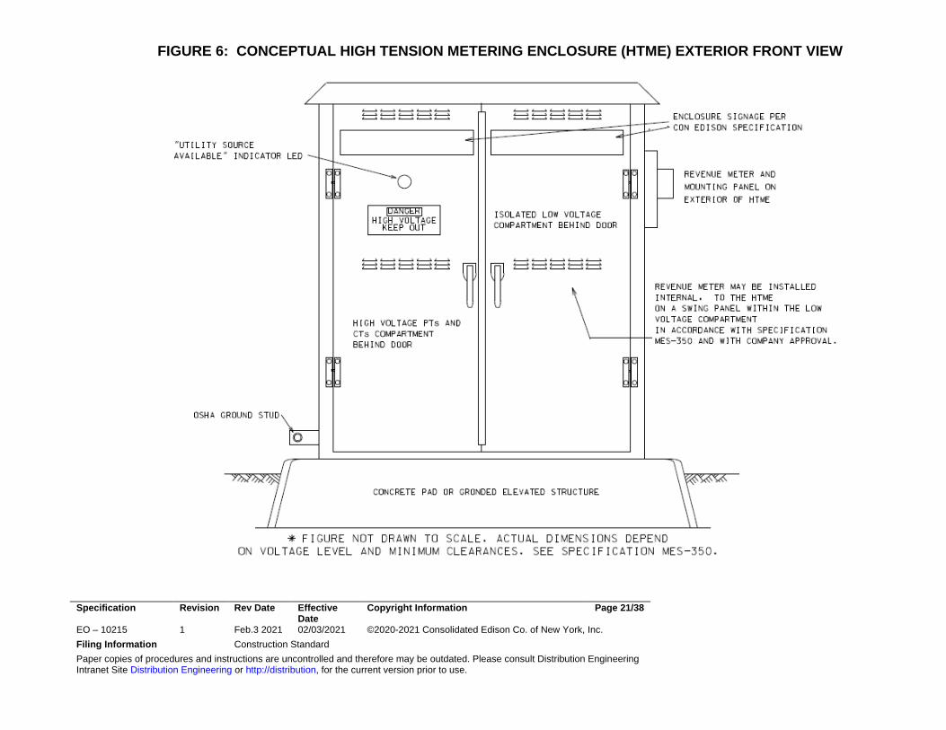
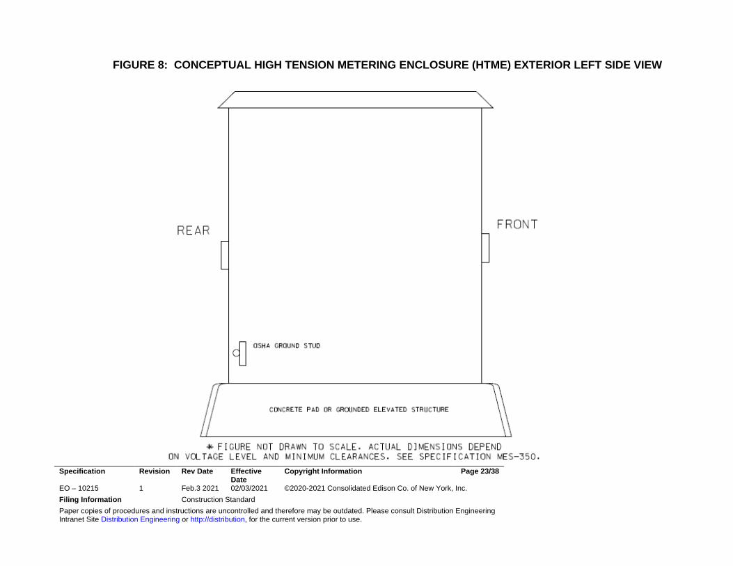
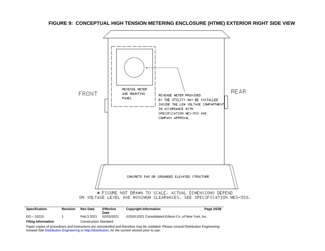
7.5 Outdoor Enclosure - Refer to FIGURES 6 through 9 as conceptual
drawings of the HTME’s exterior. These sketches are provided for guidance only. The customer shall provide a detailed set of site-specific drawings for Company review.
If the customer chooses to locate the HTME outside of a secure, environment-controlled building then they must be contained within a customer provided weather resistant metal enclosure. This enclosure shall be free-standing, ground level, and securely mounted on a level concrete pad or elevated grounded structure. It shall be located such that there are sufficient working clearances in the front and rear. The front and rear will have side-by-side hinged swing doors with mid-height locking bars to hold them open in at least two angles, 90 and 135 degrees or greater. The physical details, dimensions, NEMA rating, foundation structure, interior and exterior materials of this enclosure shall be determined by the Customer’s Engineer of Record (EOR) with compliance to code required clearances, minimum clearance around exposed live parts in the metering compartments, environmental conditions, and other conditions stipulated in Company specifications. The EOR’s signed and sealed design and material selections shall be submitted to the Company for review and approval before construction of the enclosure. This outdoor enclosure shall be considered a Company high tension vault (HTV) with an assigned number code for its known grounding point in the rear.
7.6 Equipment Elevation –
Specification Revision Rev Date Effective Date
Copyright Information Page 11/38
EO – 10215 1 Feb.3 2021 02/03/2021 ©2020-2021 Consolidated Edison Co. of New York, Inc. Filing Information Construction Standard Paper copies of procedures and instructions are uncontrolled and therefore may be outdated. Please consult Distribution Engineering Intranet Site Distribution Engineering or http://distribution, for the current version prior to use.
7.6.1 Above grade - The elevation at the bottom of the cubicle shall be
at least three (3) foot above what is shown on the current New York City or Westchester County FEMA FIRM map for the 1% annual flood risk (aka. 100 year) applicable to the chosen location. The reference elevation for the FIRM map is relative to mean sea level at Sandy Hook, unless otherwise stated on such map. Bottom entry conduits need to extend to at least the bottom plane of the cubicle to stay above this minimum height. The cubicle is allowed to be elevated above grade to clear this minimum height using a grounded structure.
7.6.2 Below grade - Below grade locations, such as building basements,
shall have to prove that adequate drainage, pumping, and spill containment facilities are present to prevent liquid from any source, including nearby tank leaks, from rising above the bottom of the cubicle.
7.7 Clearances and Security
7.8 Site Requirements - Indoor and outdoor installations of the cubicle shall be on a level surface with a level and clear perimeter around all sides for ease of personnel movement and door accessibility in the front and rear. This applies to grade level and elevated structure installations. The Customer shall maintain the level surface upon which the cubicle is installed, including the clearances around all sides of the cubicle, with protection from standing water if outdoors.
7.8.1 Front clearance - Horizontal depth of clear working space
measured from the cubicle front shall be in accordance with the applicable NESC table for the line to line voltage of exposed, unguarded live parts. The minimum depth shall be 3.5 feet. The width of clearance shall be greater than the entire width of the cubicle such that front compartment door(s) can open at least 135 degrees.
7.8.2 Rear clearance – Horizontal depth of clear working space measured from the cubicle rear shall be minimum five (5) feet regardless of voltage level. The extra clearance is due to the possibility of using hotstick or other insulated tool on the feeder termination bus OSHA grounding studs. The width of clearance shall be greater than the entire width of
Specification Revision Rev Date Effective Date
Copyright Information Page 12/38
EO – 10215 1 Feb.3 2021 02/03/2021 ©2020-2021 Consolidated Edison Co. of New York, Inc. Filing Information Construction Standard Paper copies of procedures and instructions are uncontrolled and therefore may be outdated. Please consult Distribution Engineering Intranet Site Distribution Engineering or http://distribution, for the current version prior to use.
the cubicle such that rear compartment door(s) can open at least 135 degrees.
7.8.3 Side clearance – A free standing design with 360 degree non-contact clearance from other structures prevents hidden unauthorized penetrations of compartments. Horizontal depth of side clearance, where no work or internal accessibility is expected, shall be for ease of people movement around the cubicle. A thirty six (36) inch minimum clearance is required for at least one of the sides of the cubicle
7.8.4 Vertical Clearance – clearance above the cubicle shall be allocated for small conduits needed for data communication cables, antenna, or low voltage auxiliary power if necessary, depending on location. Such conduits can only penetrate the compartment dedicated for telemetry equipment, low voltage accessories, and auxiliary power.
7.9 Bollards or other guards - If the cubicle is at risk due to its proximity to
public or private road, driveway, parking lot, or in a building’s high traffic area then the Customer shall install yellow painted bollards, or other approved guards, in locations that will block vehicles but not hinder front and rear door accessibility.
7.10 Lighting - No exterior lighting is required on the enclosure. Indoor
locations shall have sufficient lighting from either internal or external fixtures to adequately illuminate the interiors of instrument transformer, meter, and telemetry equipment compartments when their doors are open. All outdoor locations will require compartments to have interior switched LED light fixtures in all compartments.
7.11 Security - No special security, video cameras, or perimeter fencing are
required by the Company for this type of structure, though the Customer is still responsible for the cubicle’s protection on their property.
7.12 Company lock provisions - All compartments of the cubicles, shall be
manufactured with built-in hasps that can be used with a 3/8 inch padlock shackle provided by the Company to lock the respective door closed. If an outdoor enclosure is also provided, then the Company may choose to only lock the enclosure’s front and rear outer doors and not individual interior compartment doors.
Specification Revision Rev Date Effective Date
Copyright Information Page 13/38
EO – 10215 1 Feb.3 2021 02/03/2021 ©2020-2021 Consolidated Edison Co. of New York, Inc. Filing Information Construction Standard Paper copies of procedures and instructions are uncontrolled and therefore may be outdated. Please consult Distribution Engineering Intranet Site Distribution Engineering or http://distribution, for the current version prior to use.
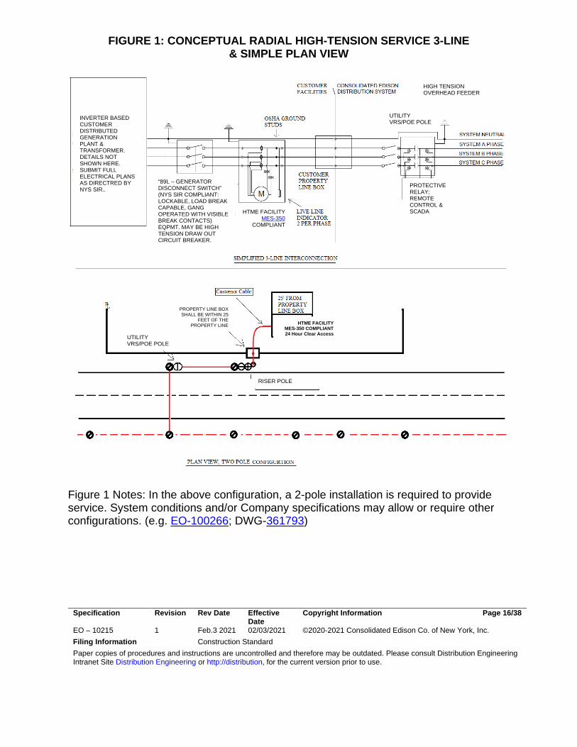
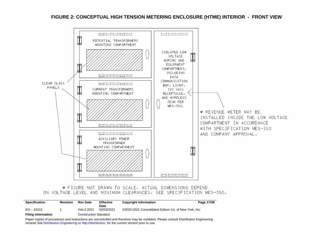
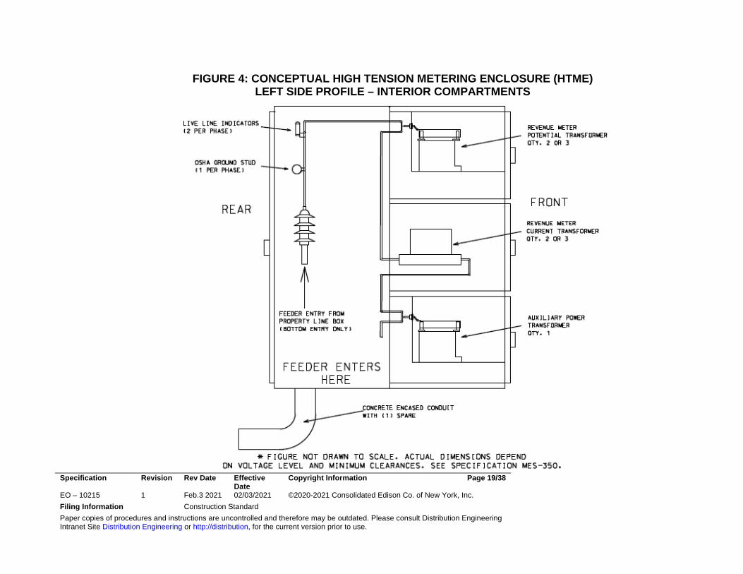
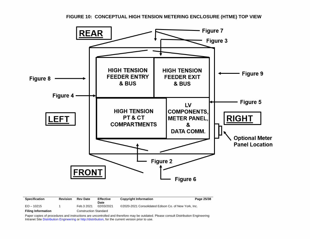
7.13 HTME Compartments -This facility shall have cubicles that isolate the components of high tension revenue metering into several compartments to ensure personnel and equipment safety, reliability, and revenue meter security. At a minimum, the following separate isolated compartments will be included in the Customer’s design. Refer to FIGURES 2 and 3 for conceptual examples of the cubicles with feeder termination and metering equipment compartments’ suggested arrangement within the interior of the HTME.
7.13.1 Utility Service ENTRY Termination Compartment – This is a
high tension isolated compartment located inside the rear section of one cubicle. This compartment shall contain the transition from Utility service entry cable into copper bus. This service ENTRY compartment is expected to be accessible from a rear door of the cubicle and is barrier isolated from the adjacent Service EXIT Termination Compartment. It shall have its own full-length hinged door with a glass window for viewing the live-line indicators and OSHA grounding studs mounted on each phase of the incoming feeder’s termination bus. Only the Company’s qualified field personnel shall have keys to unlock this compartment’s door for the purpose of applying grounding clamps to the grounding studs. This compartment shall be designed for bottom entry of the service conductors that emerge from a concrete encased duct bank.
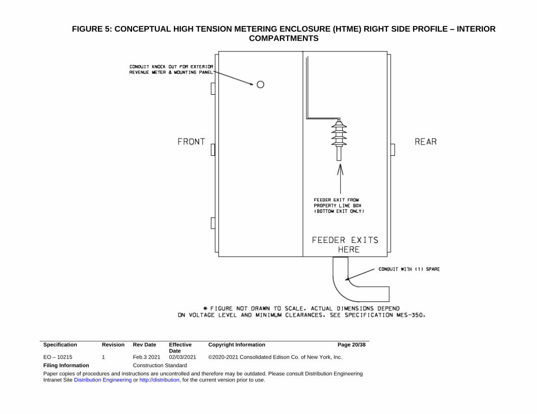
7.13.2 Utility Service EXIT Termination Compartment – This is a high
tension isolated compartment located inside the rear section of one cubicle. This compartment shall contain the transition from copper bus into customer cable as it exits the HTME and is routed directly to the first DG disconnect. This compartment is expected to be accessible from a full length locking hinged door and is barrier isolated from the adjacent Service Feeder ENTRY Termination Compartment. This compartment shall be designed for bottom exit of service conductors intended to go into a duct bank on their continuous route to the DG system’s first disconnect, unless the customer proposes a design that continues the isolated bus compartment directly from the HTME into an adjacent metal clad switchgear cubicle containing the first disconnect.
7.13.3 Low Voltage Compartment – This is an isolated space where the
Customer installs all low voltage and data communication components, such as potential transformer secondary wiring, fuse box, wireless devices, convenience lighting, 120 VAC receptacle, and thermo/hydrostats for strip heaters. Metering transformer secondary wiring conduit shall penetrate out of this compartment on
Specification Revision Rev Date Effective Date
Copyright Information Page 14/38
EO – 10215 1 Feb.3 2021 02/03/2021 ©2020-2021 Consolidated Edison Co. of New York, Inc. Filing Information Construction Standard Paper copies of procedures and instructions are uncontrolled and therefore may be outdated. Please consult Distribution Engineering Intranet Site Distribution Engineering or http://distribution, for the current version prior to use.
route to the meter mounting panel if the revenue meter is located external. Customers can propose designs that locate the revenue meter on a swinging panel inside this low voltage compartment or on the HTME’s exterior wall . The Customer shall supply the meter mounting facilities and all associated wiring, including the socket for the meter but not the meter itself, which is provided and mounted by the Company. A list of approved meter mounting equipment is contained in the Company booklet “Requirements for Electric Service Installations” under section “Approved Electric Service Equipment”. The design of this compartment and its contents, including wiring requirements and clearances, shall follow all the applicable sections of the Company’s Meter Engineering Specification MES-350 with particular attention to Section 13.
7.13.4 Revenue Meter Current Transformer Mounting Compartment –
The Customer shall furnish and install the mounting facilities for the Company provided Current Transformers (CTs) after receiving approval of their submitted design drawings of this compartment. This compartment is dedicated to only the CTs and must have safe access to install, test, and replace them. The physical arrangement of CTs, primary terminal insulated connections, and secondary wiring details are explained in the Company’s Meter Engineering Specification MES-350 and the Meter Engineering Specification Wiring Diagrams for various high tension voltage levels listed in the MES-350 References section. The Customer’s submitted drawings shall show the revenue metering CTs’ primary and secondary polarity marks. The convention used will be that the polarity mark indicating the “H1”, or “high” side, of the CT will face the direction of the Company’s incoming feeder. Using this convention, the real power (i.e, watts) imported from the feeder will be calculated in the revenue meter as a positive value. And, vice-versa, the DG power exported through the meter will be calculated as negative watts.
7.13.5 Revenue Meter Potential Transformer Mounting Compartment -
The Customer shall furnish and install the mounting facilities for the Company provided Potential Transformers (PTs) after receiving approval of their submitted design drawings of this compartment. This compartment is dedicated to only these PTs and it must have safe access to install, test, and replace them. The physical arrangement of PTs, primary terminal insulated connections, and secondary wiring details are explained in the Company’s Meter Engineering Specification MES-350 and the Meter Engineering Specification Wiring Diagrams for various high tension voltage
Specification Revision Rev Date Effective Date
Copyright Information Page 15/38
EO – 10215 1 Feb.3 2021 02/03/2021 ©2020-2021 Consolidated Edison Co. of New York, Inc. Filing Information Construction Standard Paper copies of procedures and instructions are uncontrolled and therefore may be outdated. Please consult Distribution Engineering Intranet Site Distribution Engineering or http://distribution, for the current version prior to use.
levels listed in the MES-350 References section. The primary connections of the PTs shall be made on the line side bus of the CTs (MES-350, par. 6.3).
7.13.6 Auxiliary Power Transformer Mounting Compartment – A single
PT, connected line to line on its primary and line to grounded neutral on its secondary, shall provide nominal 115 - 120 VAC power for at least the following devices provided in the customer’s design: 20 amp convenience duplex receptacle, LED compartment interior work light, two thermostat controlled anti-condensation strip heaters. This PT will be installed complete with primary fuse and secondary overcurrent protection (fuse or breaker) and all wiring. The PT and its high tension connections to the phase buses will be in this isolated compartment that is accessible to the customer behind a hinged door. The components involved and their wiring shall be line to line voltage rated and abide by the same insulation and clearances required for the revenue meter PTs. The low voltage secondary wiring and overcurrent protection from this aux. power PT will be inside the Low Voltage Compartment.
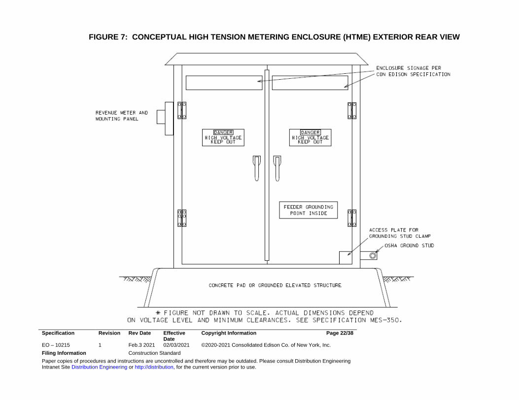
7.14 Grounding the HTME - The Customer shall provide a design for and install
a grounding method, in accordance with EO-12181-B. The cubicle and its outdoor enclosure shall be solidly grounded in 2 locations at the base of the metal structure. In addition to the approved methods of grounding addressed in this specification, the Customer shall also provide OSHA approved ground studs on the line side of each feeder termination compartment. The Customer shall also provide associated ground cables and “Shotgun” device used for detecting voltage and attaching ground cables to OSHA studs.
Specification Revision Rev Date Effective Date
Copyright Information Page 16/38
EO – 10215 1 Feb.3 2021 02/03/2021 ©2020-2021 Consolidated Edison Co. of New York, Inc. Filing Information Construction Standard Paper copies of procedures and instructions are uncontrolled and therefore may be outdated. Please consult Distribution Engineering Intranet Site Distribution Engineering or http://distribution, for the current version prior to use.
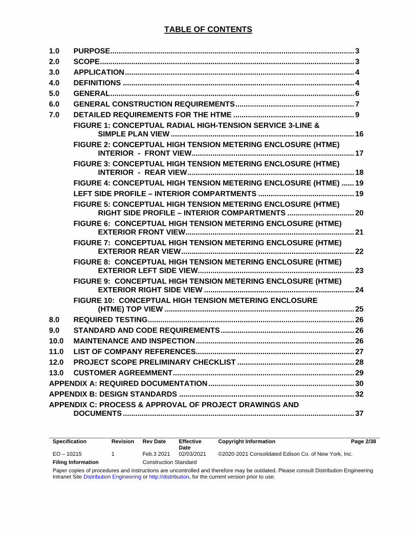
FIGURE 1: CONCEPTUAL RADIAL HIGH-TENSION SERVICE 3-LINE & SIMPLE PLAN VIEW
Figure 1 Notes: In the above configuration, a 2-pole installation is required to provide service. System conditions and/or Company specifications may allow or require other configurations. (e.g. EO-100266; DWG-361793)
HTME FACILITY MES-350
COMPLIANT
“89L – GENERATOR DISCONNECT SWITCH” (NYS SIR COMPLIANT: LOCKABLE, LOAD BREAK CAPABLE, GANG OPERATED WITH VISIBLE BREAK CONTACTS) EQPMT. MAY BE HIGH TENSION DRAW OUT CIRCUIT BREAKER.
INVERTER BASED CUSTOMER DISTRIBUTED GENERATION PLANT & TRANSFORMER. DETAILS NOT SHOWN HERE. SUBMIT FULL ELECTRICAL PLANS AS DIRECTRED BY NYS SIR..
PROTECTIVE RELAY; REMOTE CONTROL & SCADA
UTILITY VRS/POE POLE
HIGH TENSION OVERHEAD FEEDER
HTME FACILITY MES-350 COMPLIANT 24 Hour Clear Access
PROPERTY LINE BOX SHALL BE WITHIN 25
FEET OF THE PROPERTY LINE
UTILITY VRS/POE POLE
RISER POLE
Specification Revision Rev Date Effective Date
Copyright Information Page 17/38
EO – 10215 1 Feb.3 2021 02/03/2021 ©2020-2021 Consolidated Edison Co. of New York, Inc. Filing Information Construction Standard Paper copies of procedures and instructions are uncontrolled and therefore may be outdated. Please consult Distribution Engineering Intranet Site Distribution Engineering or http://distribution, for the current version prior to use.
FIGURE 2: CONCEPTUAL HIGH TENSION METERING ENCLOSURE (HTME) INTERIOR - FRONT VIEW
Specification Revision Rev Date Effective Date
Copyright Information Page 18/38
EO – 10215 1 Feb.3 2021 02/03/2021 ©2020-2021 Consolidated Edison Co. of New York, Inc. Filing Information Construction Standard Paper copies of procedures and instructions are uncontrolled and therefore may be outdated. Please consult Distribution Engineering Intranet Site Distribution Engineering or http://distribution, for the current version prior to use.
FIGURE 3: CONCEPTUAL HIGH TENSION METERING ENCLOSURE (HTME) INTERIOR - REAR VIEW
Specification Revision Rev Date Effective Date
Copyright Information Page 19/38
EO – 10215 1 Feb.3 2021 02/03/2021 ©2020-2021 Consolidated Edison Co. of New York, Inc. Filing Information Construction Standard Paper copies of procedures and instructions are uncontrolled and therefore may be outdated. Please consult Distribution Engineering Intranet Site Distribution Engineering or http://distribution, for the current version prior to use.
FIGURE 4: CONCEPTUAL HIGH TENSION METERING ENCLOSURE (HTME)
LEFT SIDE PROFILE – INTERIOR COMPARTMENTS
Specification Revision Rev Date Effective Date
Copyright Information Page 20/38
EO – 10215 1 Feb.3 2021 02/03/2021 ©2020-2021 Consolidated Edison Co. of New York, Inc. Filing Information Construction Standard Paper copies of procedures and instructions are uncontrolled and therefore may be outdated. Please consult Distribution Engineering Intranet Site Distribution Engineering or http://distribution, for the current version prior to use.
FIGURE 5: CONCEPTUAL HIGH TENSION METERING ENCLOSURE (HTME) RIGHT SIDE PROFILE – INTERIOR COMPARTMENTS
Specification Revision Rev Date Effective Date
Copyright Information Page 21/38
EO – 10215 1 Feb.3 2021 02/03/2021 ©2020-2021 Consolidated Edison Co. of New York, Inc. Filing Information Construction Standard Paper copies of procedures and instructions are uncontrolled and therefore may be outdated. Please consult Distribution Engineering Intranet Site Distribution Engineering or http://distribution, for the current version prior to use.
FIGURE 6: CONCEPTUAL HIGH TENSION METERING ENCLOSURE (HTME) EXTERIOR FRONT VIEW
Specification Revision Rev Date Effective Date
Copyright Information Page 22/38
EO – 10215 1 Feb.3 2021 02/03/2021 ©2020-2021 Consolidated Edison Co. of New York, Inc. Filing Information Construction Standard Paper copies of procedures and instructions are uncontrolled and therefore may be outdated. Please consult Distribution Engineering Intranet Site Distribution Engineering or http://distribution, for the current version prior to use.
FIGURE 7: CONCEPTUAL HIGH TENSION METERING ENCLOSURE (HTME) EXTERIOR REAR VIEW
Specification Revision Rev Date Effective Date
Copyright Information Page 23/38
EO – 10215 1 Feb.3 2021 02/03/2021 ©2020-2021 Consolidated Edison Co. of New York, Inc. Filing Information Construction Standard Paper copies of procedures and instructions are uncontrolled and therefore may be outdated. Please consult Distribution Engineering Intranet Site Distribution Engineering or http://distribution, for the current version prior to use.
FIGURE 8: CONCEPTUAL HIGH TENSION METERING ENCLOSURE (HTME) EXTERIOR LEFT SIDE VIEW
Specification Revision Rev Date Effective Date
Copyright Information Page 24/38
EO – 10215 1 Feb.3 2021 02/03/2021 ©2020-2021 Consolidated Edison Co. of New York, Inc. Filing Information Construction Standard Paper copies of procedures and instructions are uncontrolled and therefore may be outdated. Please consult Distribution Engineering Intranet Site Distribution Engineering or http://distribution, for the current version prior to use.
FIGURE 9: CONCEPTUAL HIGH TENSION METERING ENCLOSURE (HTME) EXTERIOR RIGHT SIDE VIEW
Specification Revision Rev Date Effective Date
Copyright Information Page 25/38
EO – 10215 1 Feb.3 2021 02/03/2021 ©2020-2021 Consolidated Edison Co. of New York, Inc. Filing Information Construction Standard Paper copies of procedures and instructions are uncontrolled and therefore may be outdated. Please consult Distribution Engineering Intranet Site Distribution Engineering or http://distribution, for the current version prior to use.
FIGURE 10: CONCEPTUAL HIGH TENSION METERING ENCLOSURE (HTME) TOP VIEW
Specification Revision Rev Date Effective Date
Copyright Information Page 26/38
EO – 10215 1 Feb.3 2021 02/03/2021 ©2020-2021 Consolidated Edison Co. of New York, Inc. Filing Information Construction Standard Paper copies of procedures and instructions are uncontrolled and therefore may be outdated. Please consult Distribution Engineering Intranet Site Distribution Engineering or http://distribution, for the current version prior to use.
8.0 REQUIRED TESTING 8.1 Prior to energization - The Company reserve the right to require the
customer to perform testing and allow the Company to perform tests on the combined Company/Customer facilities. 8.1.1 Primary service feeder cables and Customer terminations in
conformance with the latest revision of Company Specification EO-4019.
9.0 STANDARD AND CODE REQUIREMENTS
Unless otherwise higher requirements are noted herein, all installations by the Customer shall comply with Federal, State, and Local regulations. All equipment furnished and installed by the Customer, shall be in accordance with the latest (and most stringent) standards including but not limited to; IEEE (ANSI), NEMA, National Electric Code (NEC), National Electric Safety Code (NESC), City Administration Codes, DEP, EPA, OSHA and all applicable local codes and standards. The Company is unable to offer variances for code requirements. Projects found to be in violation of applicable codes and requirements will not be interconnected.
10.0 MAINTENANCE AND INSPECTION
10.1 Training - The Customer shall be responsible for ensuring that their designated operating personnel are trained to safely operate and perform the necessary maintenance on their high tension equipment. The Customer shall provide training to ensure that their qualified personnel are have the knowledge and skills required to safely operate and maintain the high tension electrical equipment. The Customer shall certify that employee training has been accomplished and is being kept up to date. The certification shall contain each employee's name and dates of training and the Customer shall produce this documentation on request by the Company.
10.2 Maintenance - After energization, the Customer shall be responsible
for performing routine maintenance and inspection programs of all service equipment, vaults and compartments as defined in Company Specification EO-4035. The Customer is also required to maintain an operating log and record all relay device targets and primary service feeder disconnect device trip events. The maintenance and inspection procedures and records as well as operator training and certification shall be subject to inspection by the Company.
Specification Revision Rev Date Effective Date
Copyright Information Page 27/38
EO – 10215 1 Feb.3 2021 02/03/2021 ©2020-2021 Consolidated Edison Co. of New York, Inc. Filing Information Construction Standard Paper copies of procedures and instructions are uncontrolled and therefore may be outdated. Please consult Distribution Engineering Intranet Site Distribution Engineering or http://distribution, for the current version prior to use.
11.0 LIST OF COMPANY REFERENCES EO-2115 Handbook Of General Requirements For Electrical Service To Distributed
Energy Resource (DER) Customers EO-4019 Proof Testing and Ammeter Clear Testing of Feeders and
Feeder Mains EO-4035 Operation and Maintenance of Equipment on High Tension
Customer's Premises EO-6025 Cable Arcproofing Procedures EO-6224 Requirements for Installing Direct Buried Cable in Both Public
and Private Streets EO-2468-B Cable Manhole Drawing EO-6130-C Cable Duct for Manhole Entrance Drawing, P/O EO-1042 (Pre-Cast Conduit) EO-3079-C Neon Tube Installation Drawing for Bus Type EO-10220 Numbering and Tagging of Underground Electric Distribution System
Structures MES-350 High Tension Metering Installations MES-273-A Wiring Diagram for 13 kV Metering MES-273-B Wiring Diagram for 27 kV & 33 kV Metering MES-166-A Wiring Diagram for 2.4/4kV 3 phase 4 wire Metering MES-731 and 731-A Layout and Wiring for Demand Recorder Metering MES-712 and 712-A Layout and Wiring for Panel Mount HT Metering with Network
Low Tension Auxiliary MES-713 and 713-A Layout and Wiring for Panel Mount HT Metering with Radial
Low Tension Auxiliary Company's General Instructions Governing Work on System Electrical Equipment aka the Rule Book CECONY Customer Guide to Electrical Service Installation aka the Electric Blue Book
Sergio Rodriguez (Signature on file)_____ Sergio Rodriguez Department Manager, System Design Dept. Distribution Engineering Department Steve Goldman, Andy Woo REVISION 0 Initial issue to complement EO-2115 and EO-2022
FILE APPLICATION AND DESIGN MANUAL NO. 4 FIELD MANUAL NO. 16, SECT. 4
Specification Revision Rev Date Effective Date
Copyright Information Page 28/38
EO – 10215 1 Feb.3 2021 02/03/2021 ©2020-2021 Consolidated Edison Co. of New York, Inc. Filing Information Construction Standard Paper copies of procedures and instructions are uncontrolled and therefore may be outdated. Please consult Distribution Engineering Intranet Site Distribution Engineering or http://distribution, for the current version prior to use.
12.0 PROJECT SCOPE PRELIMINARY CHECKLIST Customer’s Information Customer’s Name: _____________________________________ Customer’s Address: ___________________________________ ____________________________________ Power Clerk/CPMS Project Number Assigned _________ HTV Number assigned _________ Project Engineer assigned____________ Proposed Customer’s Service Date / / Service Voltage __Kv Number of feeders ____ Requested ____ Ruled Customer Load _____ Requested ___ Ruled Type of Customer system: Radial Service? Y / N Load side Paralleling? Y / N Autotransfer? Y / N Emergency Generators ___ No. _______ Total MW Capacity Company Supply Station ___________________________________________ Feeder Numbers and Impedance in OHMS: Feeder No. Impedance R X (Normal) Feeder No. Impedance R X (Alternate)
Please Include: Customer’s one/three line diagram & Service Information Request (SIR)
Specification Revision Rev Date Effective Date
Copyright Information Page 29/38
EO – 10215 1 Feb.3 2021 02/03/2021 ©2020-2021 Consolidated Edison Co. of New York, Inc. Filing Information Construction Standard Paper copies of procedures and instructions are uncontrolled and therefore may be outdated. Please consult Distribution Engineering Intranet Site Distribution Engineering or http://distribution, for the current version prior to use.
13.0 CUSTOMER AGREEMMENT Customer O&M Specification No. EO-............................................................ Service Location: .................................................................................... .................................................................................................................. ................................................................................................................. Consolidated Edison Company of New York Inc. Date ............................................... Company representative.......................................................................... Title ........................................................................................................... Customer contract acceptance Date .............. Customer duly authorized representative: ......................................................... Title ...................................................................................................................... _____________________________ Sergio Rodriguez Department Manager, System Design Dept. Distribution Engineering Department
Specification Revision Rev Date Effective Date
Copyright Information Page 30/38
EO – 10215 1 Feb.3 2021 02/03/2021 ©2020-2021 Consolidated Edison Co. of New York, Inc. Filing Information Construction Standard Paper copies of procedures and instructions are uncontrolled and therefore may be outdated. Please consult Distribution Engineering Intranet Site Distribution Engineering or http://distribution, for the current version prior to use.
APPENDIX A: REQUIRED DOCUMENTATION 1.0 CUSTOMER INFORMATION - Prior to the issuance of the Technical Specification,
the Customer shall submit the proposed One Line diagram(s) incorporating any existing High Tension design. The One Line diagram(s) shall be accompanied by the proposed connected and demand load data summary, load cycle profile, service description, and a preliminary short circuit and relay coordination study for Company's conceptual approval.
2.0 DER SYSTEM’S AUXILIARY LOAD DATA/LETTER - The load data summary shall
consist of a listing of all the connected and demand loads, in terms of the rated values and anticipated operating loads and standby elements. Based on the modes of operation of the Customer's loads, the Customer shall submit a preliminary daily load cycle profile. Motor load data must include the normal load level and power factor, in addition to the inrush current. The electrical starting characteristics of all high inrush current equipment shall be submitted in advance of any purchase.
3.0 CUSTOMER’S SYSTEM OPERATIONS SPECIFICATION - The Customer shall produce a System Operating document which shall detail the normal and contingency modes of operation and define all primary service disconnect switch and circuit breaker operating positions. All switching modes of operation shall be fully detailed in this document which will be finalized as an approved Customer System Operating Specification. A list of Customer key personnel that the Company may contact in the event of an emergency, with their respective telephone numbers shall be included in the final version of the Customer’s System Operation Specification. The Customer’s System Operation Specification shall be updated as required and resubmitted to the Company.
4.0 CUSTOMER TRAINING - The Customer shall provide training to ensure that their qualified personnel have the knowledge and skills required to safely operate and maintain the high tension electrical equipment. The Customer shall certify that employee training has been accomplished and is being kept up to date. The certification shall contain each employee's name and dates of training and the Customer shall produce this documentation on request by the Company.
5.0 VENDOR DATA - The Customer shall submit to the Company for approval, all vendor data concerning the primary service equipment including the equipment ratings and one line diagram. After vendor approval, the Customer shall submit; the final one line diagram, three line diagrams, control & protective relays schematics
Specification Revision Rev Date Effective Date
Copyright Information Page 31/38
EO – 10215 1 Feb.3 2021 02/03/2021 ©2020-2021 Consolidated Edison Co. of New York, Inc. Filing Information Construction Standard Paper copies of procedures and instructions are uncontrolled and therefore may be outdated. Please consult Distribution Engineering Intranet Site Distribution Engineering or http://distribution, for the current version prior to use.
including the interlocks, equipment layout drawings and the bill of materials with catalog cuts as detailed site specific design specification.
6.0 DESIGN CHANGES - During the design and construction of the project, any changes in either the loads, modes of operation, service equipment arrangement and/or interlock and protective relaying schemes from that of the approved conceptual design shall be submitted to the Company for approval and record. The Customer shall resubmit all the data as noted above with the proposed changes highlighted for the Company's approval prior to the manufacture of the service equipment.
7.0 NUMBER OF COPIES - The Customer shall transmit two (2) hard copies and corresponding digital files of each document with each submission as noted above.
Specification Revision Rev Date Effective Date
Copyright Information Page 32/38
EO – 10215 1 Feb.3 2021 02/03/2021 ©2020-2021 Consolidated Edison Co. of New York, Inc. Filing Information Construction Standard Paper copies of procedures and instructions are uncontrolled and therefore may be outdated. Please consult Distribution Engineering Intranet Site Distribution Engineering or http://distribution, for the current version prior to use.
APPENDIX B: DESIGN STANDARDS Appendix B is intended to provide an overview of the relevant Company design standards and considerations for the interconnection of distributed generation to high tension non-network feeders. Unless an otherwise higher standard is noted, where a discrepancy exists between the referenced specification or actual standard and this appendix, the reference specification or actual standard shall supersede this overview.
1.0 CUSTOMER CABLES, CONDUCTORS, & ASSOCIATED EQUIPMENT –
The Customer shall furnish and install Company approved primary service feeder cables or conductors from the property line overhead structure or underground manhole(s) to the Customer’s primary service feeder termination cubicles. The switchgear termination connections shall be made by the Customer. Customer cables or conductors shall be compatible with the size, construction and ratings of the Company primary service feeder supply. Prior to the purchase of the cables or conductors, the Customer shall submit to the Company the specifications and details of installation and connection. Any deviation from the Company standards or approved vendors (list will be provided on request) must be approved by the Company prior to the cable or conductor purchase.
1.1 Surge Protection - The Customer may opt to install surge arresters on the load
side of the primary high tension service disconnecting device for all services supplied by overhead primary service feeders. It is recommended that surge arrester sizing be in accordance with Company specification EO-2012.
1.2 Cable Terminations - The incoming feeders shall be terminated within the
termination cubicle. The Customer shall furnish and install potheads which shall be reviewed and accepted by the Company. If the Customer decides to use cold shrink type cable terminations rather than potheads for a 40 kA fault approximately 1000 N (225 lbs.) of force will be applied to the individual cables and the cold shrink support structure would need to be able to prevent the cable from whipping and at the same time protect the cable from being damaged due to said force. Here as well the Customer's selection must be reviewed for acceptance by the Company.
1.3 Live Feeder Indicators - The Customer shall furnish and install two neon glow
tubes per phase in each primary service feeder termination cubicle. The neon glow tubes shall be installed on the line side of any primary service feeder disconnecting device as detailed on Drawing EO-13079-C. Viewing windows of
Specification Revision Rev Date Effective Date
Copyright Information Page 33/38
EO – 10215 1 Feb.3 2021 02/03/2021 ©2020-2021 Consolidated Edison Co. of New York, Inc. Filing Information Construction Standard Paper copies of procedures and instructions are uncontrolled and therefore may be outdated. Please consult Distribution Engineering Intranet Site Distribution Engineering or http://distribution, for the current version prior to use.
shatter proof material shall be provided in the cubicle door(s) to permit observation of the neon glow tubes by an operator.
1.4 Ground Studs and Grounding Cables - The Customer shall install OSHA
approved type "Ball and Socket" designed ground studs (AB Chance C600-2102 or equivalent) on each bus phase in each primary service feeder termination cubicle. A ground stud shall be installed on the ground bus extended outside the cubicle to permit connection of portable ground cables. The ground studs shall be capped when not in use. The ground stud cap shall be so constructed for easy removal with a shotgun type of "hotstick." The Customer shall also provide one set of 4/0 AW, 600 Volt insulated, EPR portable ground cables with the appropriate grounding clamps (AB Chance C600-2101 or equivalent) installed. The grounding cables shall be approximately 10 foot in length and shall have a threaded grounding ferrule installed on each end. One end of the three phase cables shall have a ground clamp installed and the other end shall be joined together at a three way grounding terminal block (AB Chance PW600-0697 or equivalent) and a socket type grounding clamp. If the Customer has more than four primary service feeders a second set of portable ground cables shall be provided. The ground cables shall be hotstick operable and shall be stored at the project site in a cabinet under Company jurisdiction.
1.5 Service Neutrals - Each primary service feeder shall be furnished with a service
conductor neutral. The service conductor neutral shall be copper cable with a minimum size as noted below. The Customer shall furnish, install and connect the service conductor neutral to a ground bus within the termination cubicle.
Conductor Size/Phase Minimum Neutral Size
500 MCM 4/0 AWG 350 MCM 4/0 AWG 4/0 AWG 4/0 AWG 2/0 AWG 2/0 AWG
1.6 Bonding - Feeder cables with metallic sheaths shall have their sheaths bonded
together and shall be connected to their associated termination cubicle ground bus.
1.7 Corrosive Cable Environments - Where cables are installed in a corrosive
environment, a non-corrosive jacket shall be used on the cable. In addition,
Specification Revision Rev Date Effective Date
Copyright Information Page 34/38
EO – 10215 1 Feb.3 2021 02/03/2021 ©2020-2021 Consolidated Edison Co. of New York, Inc. Filing Information Construction Standard Paper copies of procedures and instructions are uncontrolled and therefore may be outdated. Please consult Distribution Engineering Intranet Site Distribution Engineering or http://distribution, for the current version prior to use.
cables exposed to sunlight or other forms of ultraviolet radiation shall have an approved jacket suitable for the application.
2.0 SERVICE SEPARATION
2.1 Primary Service Feeder separation outside the Customer’s substation - For
all contingency areas, primary service feeders shall be segregated such that no more than one feeder band (two primary service feeders) shall be installed on a common pole, or within the same duct bank or manhole. A minimum of twenty feet shall separate feeder bands regardless of the contingency design.
3.0 UNDERGROUND PRIMARY SERVICE CONDUIT INSTALLATIONS - All underground primary service feeder cables shall be installed in conduit. As an exception, where allowed by the Company and Municipal Code, direct buried cables may be installed in accordance with Company Specification EO-6224.
3.1 Conduit Sizing - Primary service feeder conduits supplied by the Customer shall
be sized to meet, the New York City Electrical Code, Westchester County Code, or Municipality Rules, for the number of feeders and size of the service neutral cables being installed. Each conduit shall have a minimum inside diameter of four inches regardless of code sizing.
3.2 Conduit Types - Conduits for primary cable may be of precast concrete, steel, high density polyethylene (HDPE) or fiberglass. All primary cable conduits, except precast concrete type, which are installed in heavily loaded areas such as roadways, streets and under power transformers, shall be concrete encased. All conduit ends shall be flared.
3.3 Spare Conduits - Each duct bank shall contain a minimum of one (1) spare
conduit, to facilitate repairs and minimize outage time caused by duct obstructions, as this specification is focused on interconnection to a single feeder. The spare conduits shall be sealed and capped at both ends against penetration of water and gases.
3.4 Property Line Boxes - Property line boxes shall be furnished and installed by the Customer and shall be in accordance with the Company's specifications with specific interest with EO-2468-B “Cable Manhole M11-6”. The Customer shall submit for approval, specifications for these “boxes” and facilities differing from those required by the Company. Additionally, Each property line box duct entrance shall be flared in accordance to EO-6130-D “Flared Conduit For
Specification Revision Rev Date Effective Date
Copyright Information Page 35/38
EO – 10215 1 Feb.3 2021 02/03/2021 ©2020-2021 Consolidated Edison Co. of New York, Inc. Filing Information Construction Standard Paper copies of procedures and instructions are uncontrolled and therefore may be outdated. Please consult Distribution Engineering Intranet Site Distribution Engineering or http://distribution, for the current version prior to use.
Primary Cable Manhole Entrance”.
3.5 Arc-proofing - Arc proofing of primary cables within Customer manholes is required when more than one feeder is installed within the manhole. Each primary service feeder cable shall be arc proofed in accordance with Specification EO-6025.
4.0 REVENUE METERING – The requirements listed below are the more general
requirements that would be typical for most the revenue metering at high tension installations. The detailed revenue metering requirements to be followed be the Customer are provided in detail in the Company Revenue Metering Specification MES-350.
4.1 Mounting Facilities - The Customer shall furnish, install and maintain mounting
facilities and wiring for Company meters, revenue metering instrument transformers, meter devices and phasing receptacles in accordance with Company Specification MES-350 and its support documents.
4.2 Revenue Metering Instrument Transformers - All revenue metering transformers are supplied by the Company. 15 kV class revenue metering voltage transformers will be primary fused. Other voltage class revenue metering voltage transformers will not be primary fused.
5.0 GROUND BUS – The switchgear ground bus shall be present in all compartments
where grounding of the equipment contained in the compartment is required. Equipment ground wires shall not penetrate compartment walls in order to connect to the switchgear ground bus.
6.0 GROUNDING DEVICES – Grounding devices shall meet all the operating voltage and
current requirements for switchgear except for the fault interrupting requirements.
7.0 CUBICLE DOORS - All medium voltage cubicles (front and rear) shall be accessible through padlockable hinged doors. There shall be no exposed low voltage wiring in any medium voltage cubicles.
8.0 BARRIERS AND INSULATORS - All penetrations (bus, wiring, etc.) between adjacent switchgear cubicles shall be through Company approved barriers and insulators.
9.0 FUSED LOADBREAK DISCONNECT SWITCHES & DRAW-OUT CIRCUIT
BREAKERS WITH OVERCURRENT PROTECTION - Fused load-break disconnect switches which are used as primary disconnect devices shall be electrically operable
Specification Revision Rev Date Effective Date
Copyright Information Page 36/38
EO – 10215 1 Feb.3 2021 02/03/2021 ©2020-2021 Consolidated Edison Co. of New York, Inc. Filing Information Construction Standard Paper copies of procedures and instructions are uncontrolled and therefore may be outdated. Please consult Distribution Engineering Intranet Site Distribution Engineering or http://distribution, for the current version prior to use.
from a remote panel and shall NOT have their control switches mounted on the compartment doors of the devices they are operating. The control switches shall be mounted on a separate control panel with a mimic bus, which shows equipment layout for the remote operation and status indication of the disconnect switches. Depending on the disconnect switch location, the control panel can be installed indoors, or in an outdoor environment with suitable weather protecting hardware. Fused load-break disconnect switches will be permitted on all 4 kV primary systems and on certain 13 kV primary systems in Staten Island and Westchester. A 125VDC power supply, with a charger, shall be used for all relay and control functions.
10.0 LOW VOLTAGE POWER SUPPLY - The Customer shall install a suitably sized low
voltage power supply for heaters, receptacles, internal and external lighting, etc. Any instrument transformer installed before the first point of disconnection must have Company approval and be connected phase to phase. The instrument transformer shall be able to withstand the Company cable proof testing values given in Company Specification EO-4019.
11.0 LABELS & MARKINGS - Customer's equipment shall be labelled according to the
requirements identified in Company specification EO-10220. 11.1 Nameplates and Labeling – All equipment (transformers, switchgear, etc.) shall
be furnished with permanent type of nameplates located on the equipment in a convenient location for identification. The designations to be permanently inscribed on the nameplates and shall be as shown on the approved one-line diagrams and equipment drawings. All switchgear control & protective relaying and meter devices, which are located on the cubicle doors or mimic panels shall be labeled with the specific device number.
11.2 Phase Markings – All terminations shall be labeled and marked in a permanent
manner with an appropriate code. Disconnecting switches, terminations and other equipment on three-phase services shall be marked to identify the phases properly. The first termination bus on the primary service should be so connected that the phase designations are A-B-C when facing the front of the switchgear and reading from left to right.
11.3 Terminal Blocks and Wire Markings – To facilitate maintenance and
installation, all control, alarm and protective relaying wiring and terminal strips shall be marked with permanent type markers in accordance with wire and terminal block designations as shall be noted on the wiring diagrams. See MES-350 for Revenue Metering wiring requirements
Specification Revision Rev Date Effective Date
Copyright Information Page 37/38
EO – 10215 1 Feb.3 2021 02/03/2021 ©2020-2021 Consolidated Edison Co. of New York, Inc. Filing Information Construction Standard Paper copies of procedures and instructions are uncontrolled and therefore may be outdated. Please consult Distribution Engineering Intranet Site Distribution Engineering or http://distribution, for the current version prior to use.
APPENDIX C: PROCESS & APPROVAL OF PROJECT DRAWINGS AND DOCUMENTS 1.0 Initial Project Stage – The Customer is required to submit for Company record, review
and approval, at the beginning stage of the project, the following: 2.0 Submittals – 1 set of drawings and accompanying digital files copies of the site specific
(not typical), Engineering Consultant’s One Line Diagram, which shall include Project Name & Location in the Title Box, date and revision number, approval signature and shall show quantity of each item, where more than one item is supplied. The One Line diagram shall be based on the American Society of Mechanical Engineers Electrical and Electronic Diagrams drafting practices – USAS Y14.15 – 1966 and the supplement Y14.15a – 1971and shall include the following: 2.1 Power Transformers (primary and secondary voltage, power rating, impedance
and phasor diagram)
2.2 Voltage & Current Transformers (connections and ratios) 2.3 Circuit Breakers and Loadbreak Disconnect Switches (continuous current,
symmetrical MVA ratings, and status – (N.O./N.C.)
2.4 Fuses and their ratings
2.5 Revenue Metering Transformers and Phasing Receptacles
2.6 Surge Arrester Characteristics, Control Switches, Neon indicators and Voltage and Current Instruments
2.7 Bus and Cable ratings
2.8 Grounding Devices and Ground Studs
2.9 Relaying (device No. and tripping direction) and shall show the full contact development.
2.10 Interlocking (mechanical & electrical)
2.11 Generators (type, use, size, connections and impedances)
Specification Revision Rev Date Effective Date
Copyright Information Page 38/38
EO – 10215 1 Feb.3 2021 02/03/2021 ©2020-2021 Consolidated Edison Co. of New York, Inc. Filing Information Construction Standard Paper copies of procedures and instructions are uncontrolled and therefore may be outdated. Please consult Distribution Engineering Intranet Site Distribution Engineering or http://distribution, for the current version prior to use.
2.12 Customer feeder destinations and Special Operating Details
2.13 including ATS logic and signal direction.
3.0 Final Pre-Energization Checklist - Prior to energization the Customer shall resubmit
all drawings corrected and marked FINAL and stamped by a Professional Engineer for Company record. The project site will be inspected by Company personnel, from time to time, to verify compliance with Company specifications. The Customer shall also submit for review and approval the following:
4.0 Energization - Energization will be permitted only after the successful completion of all
Company and Customer specification requirements and a finalized Customer written/Company approved Operation & Maintenance (O&M) Specification is accepted. O&M Specification shall include all normal and contingency modes of operation, including which switches are open and closed and which indicating lights will be on or off. The System Operation Specification shall include but not limited to:
i. Planned Outages on a primary service feeder. ii. Fault on the line side of a primary service feeder. iii. Fault on the load side of a primary service feeder.
The Customer shall submit all finalized documents including as built drawings. The Company will perform the required proof test on the primary service feeders up to and including the Customer's feeder terminations.