Embed Size (px)
Citation preview

Interactive image analysis as a prototyping toolfor industrial inspection
B.G. Batchelor
Indexing terms: Pattern recognition, Picture processing
Abstract: The application of an interactive image-analysis system (Susie) is demonstrated on a variety oftasks in automatic visual inspection, including: (a) the existential inspection and pitch measurement offemale screw threads; (b) checking the legibility of printing on tablets; (c) the enhancement of visibility ofindustrial radiographs; (d) detecting defects on polished metal surfaces (hydraulics cylinder bores and bright,extruded copper bars); (e) analysing the texture of machined metal surfaces; (f) locating the ends of fibre-like objects (asbestos) viewed under a microscope, as a prelude to counting them or measuring their lengths;and (g) counting, sorting and recognising defects in pressed artefacts, strewn haphazardly onto a table.Susie is ideally suited for evaluating such problems and for prototyping special-purpose visual-inspectionsystems. It is easy to learn to use Susie and, given suitable optics, an experienced image analyst can veryquickly understand the nature of the pictures he is given and develop a suitable strategy for processing them.
1 General remarks
The basis of this article is the belief that automatic visualinspection and related areas of study are vitally importantfor the development of industrial automation. The tenetsof this faith are eloquently discussed by Parks,1 althoughfurther evidence is abundant (see, for example, References2—5). In this article, inspection will be used as a genericterm, including sorting, identifying posture (of a 3-dimen-sional artefact), counting, as well as defect identification.There is a variety of tasks and a huge variation among thecomponents with which inspection is concerned. With thisin mind, the author has attempted to devise a general-purpose laboratory for studying visual inspection problems.However, no such facility can ever be truly 'generalpurpose', but, as the author hopes to show, it can besufficiently flexible to justify the use of this term. Theauthor is principally concerned with optical sensingmethods, but ultraviolet, infrared, X-rays and ultrasonicimaging systems can also be studied under the general termof Visual'. Few laboratories can equip themselves with acomprehensive range of 'illumination' sources and sensorsfor all of these methods of image formation. Even if thechoice is limited ,to optical images, there are still diffi-culties. For example, fibre-optic devices are expensive,yet viewing inside holes, or in other difficult locations,is so common a requirement6 that no truly general-purpose laboratory can afford to be without a wide rangeof such components. Nevertheless, a great deal can be donewith a few standard optical components, ingenuity and theopportunity to borrow, buy or hire more specialised piecesof equipment when they are needed. It is important to beprepared to employ incremental simulation wheneverpossible.7 Another important point is that general-purposesoftware is likely to be slow in execution compared, say, tospecially designed hardware. The user of the prototypingsystem must be convinced of this.
Visual inspection is widely adopted in industry and itsuses vary from gross defect detection of metal stampingsto examination of the surface finish on painted objects,from bruise detection of apples to inspecting the labels on
Paper T333C, first received 6th October 1978 and in revised form7th February 1979Dr. Batchelor is with the Department of Electronics, University ofSouthampton, Southampton SO9 SNH, England
COMPUTERS AND DIGITAL TECHNIQUES, APRIL 1979, Vol. 2, No. 2
confectionary bars. The quality-assurance manager may askhow he can be reasonably certain that a machine can takeover these and other inspection tasks that have hithertobeen prerogatives of human beings. There is no simplereply, but convincing the manager is one thing that aprototyping system is specifically intended to do. Susie,the interactive image analyser discussed in this paper, issuch a system and can be used, with relatively little effort,to give at least a tentative answer to this question. However,as a general rule, if a person with normal sight cannot seethe fault or other feature that it is required to detect, thenno machine can. With the one possible exception of decon-volving blurred images, there is no other instance, to theauthor's knowledge, where the above rule is violated.
2 Interactive image analysis
The primary objective of this article is to emphasise theusefulness of interactive image analysis as a prototypingtool for industrial inspection. To do this, we shall discussa number of case studies. We begin, however, by brieflyconsidering other work in this area and thereby placingour own in context.
Interactive image analysis is not new, despite the factthat the authors of textbooks have almost completelyignored the topic. A literature survey,* conducted inNovember 1978, revealed 26 articles relating to the designof an interactive image analyser, 22 relating to the applica-tion of such a device in biomedicine, 13 to aerial/satellitephotographs, 13 to other disciplines (including radar,microscopy, climatology, nuclear physics and opticalcharacter recognition, but excluding industrial inspection)and 6 to various other topics which were not easily classi-fiable. Only three articles could be found which related tothe application of an interactive image analyser to industrialproblems.8"10 On closer examination, it was found thatonly the last of these has any direct relevance to the presentpaper; it discussed one specific application, namely, that ofanalysing textile patterns.
There is, of course, a considerable corpus of literaturerelating to robot vision, but, despite extensive searching,
*The search profile was(interact.) and (image or picture) and (analysis or processing)
The search was based upon the INSPEC files and covered thepreceding seven years. A total of 131 articles was found of which48 were irrelevant to the subject of this paper
61
0140-1335/79/020061 + 10 $01.50/0

the author has not found any publications which emphasisethe use of interactive design methods for such systems.
Susiet is the interactive image analyser used in the experi-ments reported below. It is based upon a conventionalminicomputer, uses established software practices andimplements standard picture-processing operations,descriptions of which may be found in any good text-book. Susie does not, of course, implement all of thefunctions described in these books; new ones are addedwhen they are needed. (It is an important feature of thesystem that this can be done with a minimum of incon-venience.)
It is worth pointing out that, for industrial applications,where processing speed is important, certain types ofalgorithm are impracticable (far too slow for implemen-tation by a serial processor, and too expensive when imple-mented on a parallel machine). Also, for very manyindustrial tasks, monochrome images suffice. This is incontrast to aerial photography, where coloured/multi-spectral images abound. (Thus far, we have only usedcolour information in a very simple way;by using colouredlighting, it is possible to highlight certain features of animage, while obscuring others.)
Industrial inspection differs from all of the other majorapplications areas, except fixed-font o.cr., in that the formof the ideal image is known beforehand. The size and shapeof, say, a human kidney, as it appears in an X-ray, is highlyvariable, depending upon such factors as age, sex, diseaseand medical treatment, as well as the variability of dif-ferent individuals. Similarly, a missile site, in an unfriendlycountry, has no well-defined form in an aerial photograph.On the other hand, a 2BA screw with a round head hasa shape that is known to within close tolerances. A greatdeal of useful work can be achieved in industrial inspectionusing monochrome images which are subjected to fairlyobvious forms of image interpretation, following suitablepreprocessing, to filter, enhance and extract from theimage some suitable features. Industrial inspection is stilla largely unexplored applications area for picture pro-cessing. Interactive image analysis is one way of assistingthis exploration. To use an analogy, interactive imageanalysis provides a 'bag of tools' for picture processing.A plumber takes certain tools with him when he goes to ahouse to perform some repairs. A carpenter takes a dif-ferent set. An image analyst working on biomedical mater-ial needs different 'tools' from one working on inspection;some may be common, but not all.
In the limited space available in a journal article, it ishoped to show that the set of image-analytic tools availableon Susie is a useful one for industrial inspection and thatthey function within a very convenient operating protocol.
2. / Introduction to Susie
Susie is a hardware-software complex, centred on a conven-tional minicomputer, and is used principally for analysingpictures as a prelude to devising a (more efficient) special-purpose picture-processing system. The system architectureand memory map are shown in Fig. 1 and further detailsare given in the Appendixes 7.1 and 7.2. Using Susie isstraightforward; the user can select any of about 90 picture-processing operators, simply by typing a 2-letter mnemonic.'Susie is the acronym for Southampton University System forImage Evaluation. Susie was originated by Dr P.J. Biumfitt, withwhom the author had the pleasure of working for two years. Thesystem was extended by the author. A detailed description of(basic) Susie wiU be published by Dr. Brumfitt in due course
An essential feature of the system is the facility for display-ing pictures immediately the processing is complete.t Theresponse to individual commands is rapid (0*5 —2s formost operators), thereby allowing the user quickly to gaina 'feel' for the pictures and to devise an appropriate analysisstrategy for them.
Static television pictures may be digitised, or previouslydigitised images may be input from paper tape, magnetictape, floppy disc or from an analogue tape recorder. Imagesmay be stored on the digital tapes for subsequent process-ing or transferred, for further analysis, to another, largerminicomputer (Modcomp IV). Images generated by thismachine may be transferred back to Susie for display and/or further processing. The Susie user can also control theModcomp IV processor from the 'soft' console (while stillcontrolling Susie with the 'hard' console). Alternatively,he can route data from the Susie complex to the ModcompIV processor, or vice versa.
The computer system, however complicated, cannotcompensate fully for poor input images, and, for thisreason, it is necessary to pay attention to the illumina-tion of the objects which are to be examined by Susie.A variety of optical components are essential in a lab-oratory such as ours. These include colour filters, prisms,mirrors, lenses, various light sources (lasers, thyristor-controlled floodlights, a light box for viewing silhouettes),clamps for holding samples, black cards and black cloth etc.These are all important, if seemingly mundane. Fibre-optic devices for illuminating and viewing in difficultsituations, for example, inside holes, are also valuable,although expensive. Our aim has been to develop a 'general-purpose' laboratory for prototyping automatic visualinspection systems and, to this end, these 'mundane'components are essential. To paraphrase our experience:the curtains on the windows are as important as thesoftware.
3 Using Susie
3.1 Existential inspection and pitch estimation forfemale screw threads
Using an optical system, such as that shown in Fig. 2, itis possible to obtain a good-quality image of a femalescrew thread. One such image is shown in Fig. 3a, and theresults of various types of processing in Fig. 3b— I. All ofthis processing was completed in about lh,§ includingthe time to experiment and optimise the analysis. Fig. 3bwas drawn using a long sequence of Susie commands"which has been defined as a macro. Once a macro hasbeen defined, it may be executed simply by calling it byname, just like any other Susie command. Notice thelogarithmic ordinate (frequency) scale of the histogramin Fig. 3c and that it is not possible to threshold Fig. 3asuccessfully, owing to variations in the image intensityresulting from the nonuniform illumination (Fig. 3d).Even after heavy attenuation of high spatial frequencies,the image of the thread is still clearly visible (Fig. 3e).This is a much 'smoother' image than Fig. 3a, and dif-t All of the half-tone illustrations in this article were obtained byphotographing the display monitor§In fact, all 41 of the half-tone illustrations in this article werecollected in about 8 hours. This includes the experimentationtime, during which the author was trying to decide what to do!In the following command string, WX produces an intensity
wedge varying along the x-axis, and EX interchanges the picture filesA and B (See Appendix 6.2). The following sequence draws anintensity plot such as that in Fig. 36):YX; PS 64, 0; CS; EX; WX; SU; TH 32; GR; YX
62 COMPUTERS AND DIGITAL TECHNIQUES, APRIL 1979, Vol. 2, No. 2

Silentkeyboard& textdisplay
"soft" console
VideoMonitor
Display
CCTVCamera
V.D.U.
Analoguetaperecorder
Joystick
Teletypewriter
VideoTapeRecorder
Switchingunitfmanual
P D P - 12
processor
ADC
ADC
"hard" console SUSIE hardware
Real-timeclock
Graphplotter
2 LINCtapetransports
MODCOMPIV
Processor
Movingheaddisc
Other facilitiesinclude: HoneywellDDP516 satelliteprocessor; graphics;draughting plotter;paper tape punch &reader; EPROMprogrammer; userconsoles
2 floppydiscs
FORTRAN IV host processor
to display monitor
Asoftware- controlledswitch (also operatedby a single key onthe console)
Fig. 1 Susie
a Susie architectureb Memory map
optic axist
picture file A
picture file B
s.u.s.i.e. system andpermanent commands
library (user-loadablecommand set)
overlay (singlecommand)
0 kwords
8 kwords
16 kwords
24 kwords
30 kwords
32 kwords(1 word3i2 bits)
halfsilveredmirror
\
"silvered cone
surface beinginspected
lensphotodiode array
image (r,9) plane to a.d.c.andcomputer
attenuator
collimatedlight
Fig. 2 Imaging system for examing an internal cylindrical surface,such as a threaded hole1*
ferentiation can safely be applied to it. The result (afterrescaling so that high contrasts are visible) is shown inFig. 3/, while simple thresholding on this yields Fig. 3g.By detecting the edges in this Figure, we obtain the imageshown in Fig. 3h. When these edges are superimposed ontothe original, we see that they correspond clearly to thesubjective impression of the intensity peaks and troughs(Fig. 3/). The intensity contours of Fig. 3e are shown inFig. 3/, whereas those produced from Fig. 3a (Fig. 3d)are much more 'ragged' in appearance. Quite a differentsubjective impression of an image may be obtained afterits intensity scale has been transformed; compare Figures3a, 3k and 3/.
From Fig. 3h, it would be a simple matter to verify thatthere is a thread and measure its pitch. Details of thenecessary calculations are given in References 13 and 14.
3.2 Testing the legibility of printing (on a circularartefact such as a tablet)
This is a rather simpler process than the one just described.We begin by isolating the printing. This is a simple matterof choosing an appropriate threshold, after examining thehistogram and finding the valley (Fig 4a.) This black/white printing (Fig. 4c) is then used to mask the intensitycone shown in Fig. 4b. The centre of this cone is made tocoincide with the centre of the tablet. While image pro-cessing methods exist for finding the centre of a circularobject, given its silhouette,15 it would probably be cheaperto employ some mechanical means of centering the tablet.The results, using two samples of printing, are shown inFigs. 4d and 4e, together with their corresponding histo-
COMPUTERS AND DIGITAL TECHNIQUES, APRIL 1979, Vol. 2, No. 2 63

Fig. 3 Female screw-thread images
a Original [the significance of the white lines at ±22-5° is ex-plained in (/)]b Intensity plotted against distance measured across the centre of(a)c Histogram of (a). The histogram is comblike because the authormanually stretched the intensity scale (using SH and LA) to obtaingood contrast for photographyd Threshold of (a). It is not possible to threshold (a) successfully,owing to the intensity variations which result from the nonuniformillumination. Notice the 'ragged' edgese Lowpass filtering of (a) (GP applied five times)/ Horizontal derivative of (e) (using GP), followed by histogramequalisation (HQ). The differentiation procedure is sensitive tonearly-vertical edges and thus is inappropriate outside the segmentdefined by a pair of straight lines at ± 22-5° [see part (a)]g Threshold of (/) (TH)h Edges detected in (g) (using GP)i Edges superimposed on the original (using MI)/ Intensity contours of (e). Those of (a) are very ragged in appear-ance [see (d)]k Histogram equalisation of (a) (HQ)/ Image obtained after forcing the histogram to take the formea-1 where / is the intensity and a is a positive constant
grams. Slight, differences in these histograms may be seenon the left. The logarithmic scale on their ordinate axeshas compressed the differences and made them appearto be smaller than they would if linear frequency scaleswere used. If /) and // denote the two (linear) histogramswhich are both functions of intensity / (e [black, white]),then we may test the legibility of the printing by com-puting some metric such as
Max (I/, -fl\lft)
and then comparing this to some predefined toleranceparameter (Fig. 4/). Such a test is rotation invariant, but itis sensitive to registration and magnification. However,neither of these is likely to be troublesome in practiced
"Mechanical or image analytic methods of centring are both veryaccurate. The writing is added with a fixed printing head
When the writing does vary in registration and orien-tation, but not magnification, it might be more appropriateto normalise, by calculating the centroid of the black/white printing, and then shift the image so that this coin-cides with the centre of the cone. This method might beused to check that printed wrappers have been fittedcorrectly, so that the name of the product is visible.
3.3 Image enhancement of radiographs and surfaces
It is not always necessary, nor even desirable, to replacethe human inspector.16*17 It may, in some instances, berequired to assist him by preprocessing the images beforethey are displayed. This is the area termed image enhance-ment.11 Fig. 5 shows some of the possibilities. Theimproved image quality is probably just good enough(Fig. 5/) to ensure that an automatic existential inspectionsystem would operate satisfactorily, particularly if theimage registration is precise; if we know where to look inan image, it is relatively easy to verify that a particularfeature is present. For example, the inclined contours,around the head of the countersunk screw, would beuseful indicators of its presence. A similar system to Susieis under development for the specific task of analysingradiographs.18 Rutovitz etal.7 and Balston17 both advocatethe use of an interactive image-enhancement system,albeit for nonindustrial applications.
3.4 Surface defec t inspec tion
Two examples are illustrated in Fig. 6 and another inFig. 7. In this area of study, the greatest skill is needed inchoosing the method of illumination and viewing. (Whatcolour of light should be used? What are the best angles ofview and illumination?) Notice the importance of inter-preting the processed images; it is essential to distinguishbetween the (expected) hole, the benign stain and thedangerous scratch in Fig. 6a. A scratch may be regarded as
64 COMPUTERS AND DIGITAL TECHNIQUES, APRIL 1979, Vol. 2, No. 2
I l l l l l l l l l l l l l l l l l l l l l l l l l l
PICTURE
2-5
20
1-0
10 20 30intensity, i
Fig. 5 Image enhancement of the radiograph of a countersunkscrew and washer in a complex assembly
a Originalb Histogram equalisation (HQ) applied to (a)c Improved contrast of the original, achieved by (manual) selectionof the intensity shift (SH) and intensity double (LA) function.Although this was guided manually, the intensity normalisationprocess could be specified as an algorithm. This is an example ofwhat might be termed 'the user playing algorithmically'd Exponential intensity transform (ET) applied to (c)e The result of performing the operation sequence: equalise histo-gram; lowpass filter; equalise the histogram/ SC3 (reduce the grey-scale resolution to 3 bits), applied to (e).The sharp edges in this image provide important visual cues to thehuman interpreter and would also assist a mechine. Thus, theexistence of the edges inclined at roughly ± 45°, could be taken asa useful indicator of the presence of the screw
Fig. 4 Testing the legibility of printing on a circular artefact suchas a tablet
a Histogram of the grey-scale image of the printing (dark grey) on(light grey) paper. Thresholding in the valley (indicated by the whitetick mark) produces nearly optimal separation of the printing andbackgroundb Intensity conec Two samples of printingd Grey-weighted printing and its histogram, for the defectivesample. (By 'grey weighting' we mean that the writing is used as amask which is placed over the intensity cone)e Grey-weighted printing and its histogram for the perfect sample/ Graph of the function |(/(- —//)!/ / ,- against j
cig. 6 Images derived from the internal surface of an hydraulicscylinder using a laser flying-spot scanner
a Original and its histogram. Notice that the very dark ellipticalregion corresponds to a port opening into the cylinder and thatthe irregularly shaped dark regions are stains on the surface. Abouttwo-thirds of the way across the bottom, traversing from left toright, there is a short, vertical, dark scratch which is obscuredbecause it lies within a dark areab Another sample. Left, the original; right the scratches have beendetected. The processing used was a variant of lowpass filteringbut using LN instead of LP
COMPUTERS AND DIGITAL TECHNIQUES, APRIL 1979, Vol. 2, No. 2 65
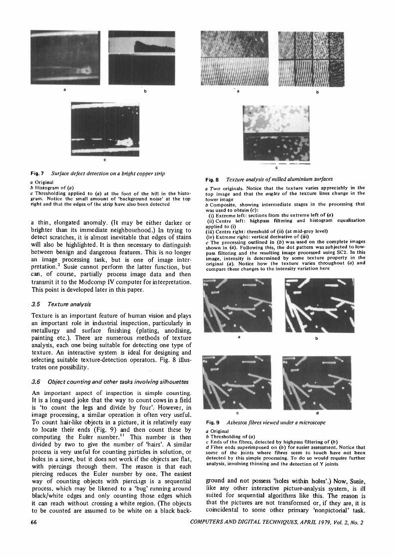
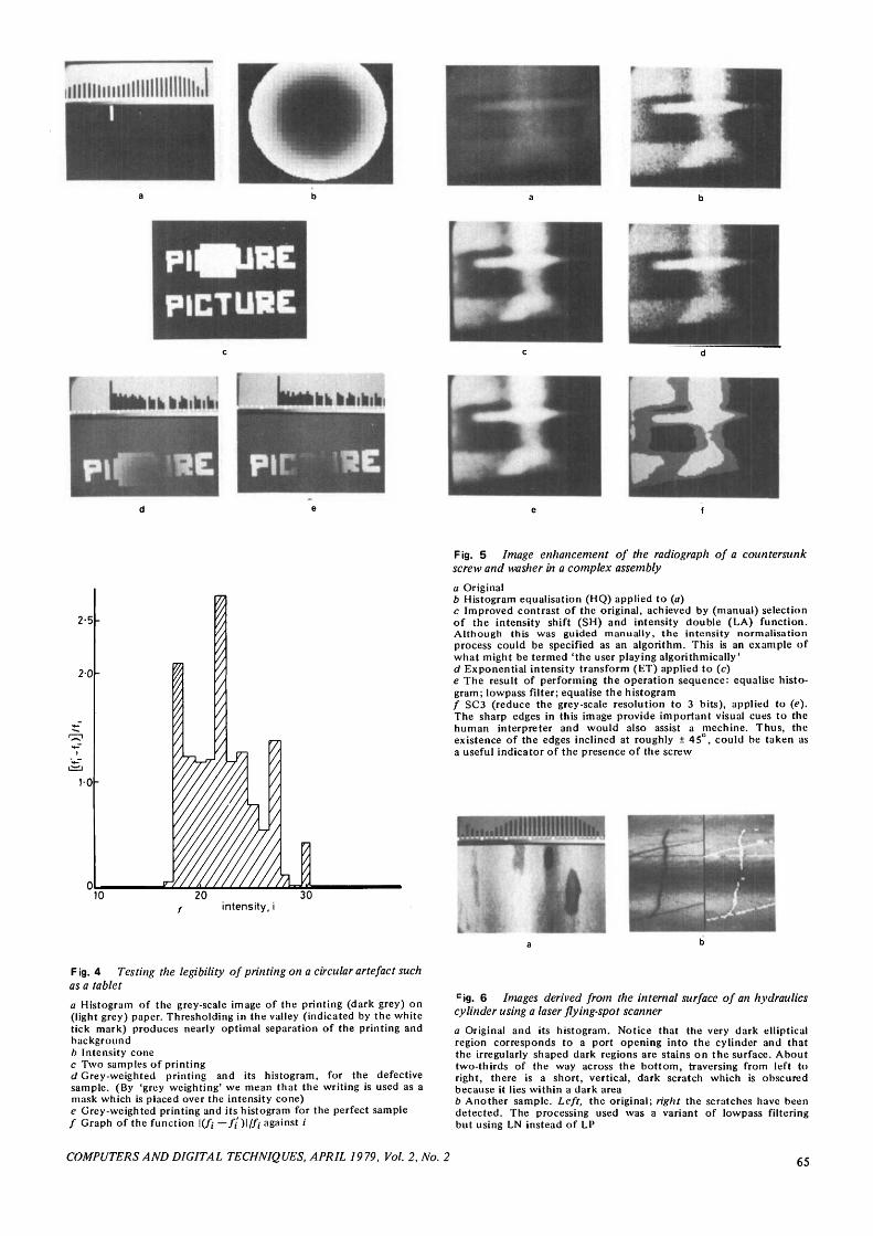
Fig. 7 Surface defect detection on a bright copper strip
a Originalb Histogram of (a)c Thresholding applied to (a) at the foot of the hill in the histo-gram. Notice the small amount of 'background noise' at the topright and that the edges of the strip have also been detected
a thin, elongated anomaly. (It may be either darker orbrighter than its immediate neighbourhood.) In trying todetect scratches, it is almost inevitable that edges of stainswill also be highlighted. It is then necessary to distinguishbetween benign and dangerous features. This is no longeran image processing task, but is one of image inter-pretation.2 Susie cannot perform the latter function, butcan, of course, partially process image data and thentransmit it to the Modcomp IV computer for interpretation.This point is developed later in this paper.
3.5 Texture analysis
Texture is an important feature of human vision and playsan important role in industrial inspection, particularly inmetallurgy and surface finishing (plating, anodising,painting etc.). There are numerous methods of textureanalysis, each one being suitable for detecting one type oftexture. An interactive system is ideal for designing andselecting suitable texture-detection operators. Fig. 8 illus-trates one possibility.
3.6 Object counting and other tasks involving silhouettes
An important aspect of inspection is simple counting.It is a long-used joke that the way to count cows in a fieldis 'to count the legs and divide by four'. However, inimage processing, a similar operation is often very useful.To count hair-like objects in a picture, it is relatively easyto locate their ends (Fig. 9) and then count these bycomputing the Euler number.11 This number is thendivided by two to give the number of 'hairs'. A similarprocess is very useful for counting particles in solution, orholes in a sieve, but it does not work if the objects are flat,with piercings through them. The reason is that eachpiercing reduces the Euler number by one. The easiestway of counting objects with piercings is a sequentialprocess, which may be likened to a 'bug' running aroundblack/white edges and only counting those edges whichit can reach without crossing a white region. (The objectsto be counted are assumed to be white on a black back-
Fig. 8 Texture analysis of milled aluminium surfaces
a Two originals. Notice that the texture varies appreciably in thetop image and that the angles of the texture lines change in thelower imageb Composite, showing intermediate stages in the processing thatwas used to obtain (c):
(i) Extreme left: sections from the extreme left of (a)(ii) Centre left: highpass filtering and histogram equalisation
applied to (i)(iii) Centre right: threshold of (ii) (at mid-grey level)(iv) Extreme right: vertical derivative of (iii)c The processing outlined in (6) was used on the complete imagesshown in (a). Following this, the dot pattern was subjected to low-pass filtering and the resulting image processed using SC2. In thisimage, intensity is determined by some texture property in theoriginal (a). Notice how the texture varies throughout (a) andcompare these changes to the intensity variation here
Fig. 9 Asbestos fibres viewed under a microscope
a Originalb Thresholding of (a)c Ends of the fibres, detected by highpass filtering of (b)d Fibre ends superimposed on (6) for easier assessment. Notice thatsome of the joints where fibres seem to touch have not beendetected by this simple processing. To do so would require furtheranalysis, involving thinning and the detection of Y joints
ground and not possess 'holes within holes'.) Now, Susie,like any other interactive picture-analysis system, is illsuited for sequential algorithms like this. The reason isthat the pictures are not transformed or, if they are, it iscoincidental to some other primary 'nonpictorial' task.
66 COMPUTERS AND DIGITAL TECHNIQUES, APRIL 1979, Vol. 2, No. 2
However, Susie has a role to play in preparing the imagesin a suitable form for such a sequential algorithm. Let ustherefore illustrate this preprocessing and in the followingSection explain the mechanics of transfering data to thesatellite, Fortran-host processor (Modcomp IV in Fig. 1).
In Fig. 10a, the original image, obtained by back lightinga number of flat metal artefacts, is shown, while its histo-gram is shown in Fig. \0b. The 'foot' of the peak in thishistogram (level 46, light grey) is the obvious position forplacing a threshold, and the result of performing thisoperation is shown in Fig. 10c. It is usually most conven-ient to supply 'bug' programs with edges (Fig. lOd) ratherthan solid images, and this often results in a considerablesaving of storage and processing time. The overlap inFig. \0a—d makes the identification and counting of theobjects rather difficult. These tasks are much easier if theobjects can be separated mechanically (Fig. lOe). However,if counting is required and the objects touch or overlaponly slightly, it is possible to segment the image by shrink-ing the bright areas.19 This can be accomplished easily bySusie (Fig. 10/).
Fig. 10 Object counting and silhouette description (as a preludeto shape analysis)
a Original. Back lighting was employed to obtain a high contrastb Histogram of (a)c Result of thresholding (a) at level 45 (light grey). This correspondsto the point where the plateau in (6) joins the peakd Differentiated version of (c). The image in (a) requires the storage,and processing, of over 1-2 X 10s bits, while that in (c) requires (aminimum of) 16384 bits and that shown here less than 1000 bits. Inpractice, it is usual to process edge-coded data whenever possible,to make use of the large improvement in the quantities of datawhich have to be storede Well-separated components. These can be counted easily, by avariety of techniques, whereas those in (c) cannot, because there issome overlap between components. Identifying the overlappingcomponents is feasible but it is far better to avoid the situation, ifit is possible to do so/ When components without holes overlap slightly, as at the leftof this image, they can be separated by shrinking them until the'neck' between them breaks. Once they have been separated, as atthe right, the objects can be counted simply by calculating the Eulernumber"
3.7 Some things Susie cannot do
It is well to record that not all image analysis operationslend themselves to interaction. For example, a 2-dimen-sional Fourier transform, or correlation, is so slow inexecution that the user would quickly become very boredwaiting for the results of these operations. Many so-calledimage-processing operations are not transformations ofimages to images, but may be, for example, data string todata string, or, as we shall discuss below, data string to tree.This type of operation is best executed using a high-levelalgorithmic language; in the absence of any tiling better,Fortran will suffice. The architecture of Susie (Fig. 1)should be recalled. Notice that there is a link to a Fortranprocessor. This was installed specifically to facilitateoperations of the types we have just described. The Susie/Modcomp IV data link has several modes of operation(see Appendix 6.2). Using these, it is possible to digitiseand 'predigest' pictorial data, ready for analysis by non-
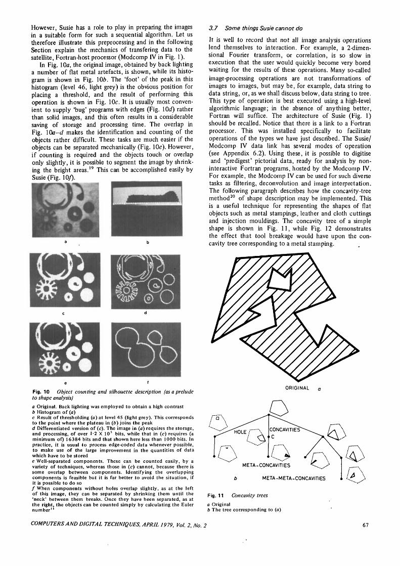
interactive Fortran programs, hosted by the Modcomp IV.For example, the Modcomp IV can be used for such diversetasks as filtering, deconvolution and image interpretation.The following paragraph describes how the concavity-treemethod20 of shape description may be implemented. Thisis a useful technique for representing the shapes of flatobjects such as metal stampings, leather and cloth cuttingsand injection mouldings. The concavity tree of a simpleshape is shown in Fig. 11, while Fig. 12 demonstratesthe effect that tool breakage would have upon the con-cavity tree corresponding to a metal stamping.
ORIGINAL a
META-CONCAVITIES
b META-META-CONCAVITIES
Fig. 11 Concavity trees
a Originalb The tree corresponding to (a)
COMPUTERS AND DIGITAL TECHNIQUES, APRIL 1979, Vol. 2, No. 2 67

Suppose that a metal stamping is viewed in silhouette(i.e. using back lighting) and that the resulting image isthreshold and differentiated, as described in Fig. 10. Fromthe resulting binary image, the chain code21 is calculatedby Susie and transmitted, via the data link, to the Mod-comp IV processor. The latter system runs the Fortranprogram which calculates the concavity-tree structuredescribing the shape of the metal stamping. In this example,it is not necessary for the Modcomp IV to send a pictureto Susie, but this is perfectly feasible.
TL
(C)
F ig. 12 Concavity tree of a flat metals tamping
a Perfect objectb Defective stampingc Concavity tree corresponding to (a). The effect of the defect isto remove the node labelled TL. (Nodes labelled 'H' correspond toholes in (a), while labels B, R, etc. denote Bottom, Right, etc.)
4 Conclusion
The use of an interactive picture-analysis is best demon-strated 'live'; a written paper is a very poor substitute forwitnessing or, better still, controlling Susie as it transformsimages from poor visibility to good. Nevertheless, theversatility of the system has been demonstrated in thevaried image-processing tasks which have been described.The system is constantly under development; new image-processing functions are being added almost every week.A second-generation system is currently being designedaround a microprocessor which hosts Fortran. The soft-ware of the existing system is written in assembly code,while that of the new will be in Fortran. The new hard-ware will comprise a cheap 'bolt-on' facility, for inter-facing to almost any mini- or microprocessor which canhost Fortran. The new system will hold four picture filesin fast r.a.m., thereby improving the response tirnes of somefunctions and facilitating others. More important than thiswill be the facility for digitising a single television frameand thereby allowing video recordings to be digitised. Thisand the light-weight equipment required for the second-generation Susie will allow it to be used for in situ datacollection, from a factory or laboratory.
5 Acknowledgments
The author's gratitude is extended to the following peopleand organisations: P.J. Brumfitt, who together with theauthor developed the Susie software; T.B. Le M. Holland,who developed its hardware; Procurement Executive,Ministry of Defence, who sponsored the development ofSusie; H.L. Al Sa'edy, M. Carrington (both of University ofSouthampton), who provided data for Figs. 9 and 8,respectively; C. Sandors (Triad Computing Systems Limited)for the data used in Fig. 5; B.M. Colgate (Lucas GirlingLimited) for the data used in Fig. 6; D.A. Hill (Capital(U.E.) Limited) for the data used in Fig. 7 (and for suggest-ing the problem outlined in Section 3.2). Figs. 11 and 12are being published simultaneously in Reference 20.
6 References
1 PARKS, J.R.: 'Industrial sensory devices', in BATCHELOR,B.G. (Ed.): 'Pattern recognition: ideas in practice' (Plenum,NY 1978)
2 HALE, J.A.G., and SARAGA, P.: 'Digital image processing',in BATCHELOR, B. G. (Ed.): 'Pattern recognition: ideas inpractice' (Plenum, NY, 1978)
3 Proceedings 2nd International Conference on AutomatedInspection and Product Control, 1976, Published by IITResearch Institute, Chicago, USA
4 Proceedings 3rd International Conference on Automated Inspec-tion and Product Control, 1978, Nottingham, England, Pub-lished by International F;luidics Services, Kempston, Bedford,England and IIT Research Institute, Chicago, USA
5 Proceedings 4th International Conference on AutomatedInspection and Product Control, IITRI, Chicago, USA, Nov.1978, Proceedings published by IITRI and InternationalFluidics Services, Kempston, Bedford, England
6 HILL, D.A.: 'Fibre optics' (Business Books, London, 1976)7 RUTOVITZ, D., GREEN, D.K., FARROW, A.S.J., and MASON,
D.C., 'Computer assisted measurement in the cytogenetic lab-oratory', in BATCHELOR, B.G. (Ed.): 'Pattern recognition:ideas in practice' (Plenum, NY, 1978)
8 CHIEN, J.T., and KILLEEN, T.J.: 'Pattern recognition and oilidentification'. IEEE Workship on pattern recognition appliedto oil spill identification 1121022, 11-12 November 1976,Coronado California, 173, pp. 15-33, 1977
9 AGIN, G.J., and DUDA, R.C.: 'SRI vision research for advancedindustrial automation'. 2nd USA Japan Computer ConferenceProceedings 913092, 26-28 Aug. 1975, pp. 113-117, 1975
10 SAKAI, T., NAGEO, M., and KONINISHI, O.: 'On-line pictureprocessing of textile patterns'. System Computer Control(U.S.A.) 4, 757252 syccb, July-Aug. 1973, pp. 1-6
11 ROSENFELD, A., and KAK, A.C.: 'Digital image processing'(Academic Press, New York, 1976)
12 GONZALEZ, R., and WINTZ, P.: 'Digital image processing'(Addison-Wesley, Reading, USA, 1977)
13 BATCHELOR, B.G.: 'Proposals for the automatic visual inspec-tion of female screw-threads'. Proceedings 3rd InternationalConference on Automated Inspection and Product Control,1978
14 BATCHELOR, B.G.: 'Automatic visual inspection of femalescrew threads'. Proceedings Conference on Measurement andControl (MECO '78), Athens, Greece, published by PanhellenicSociety of Mechanical and Electrical Engineers/InternationalAssociation of Science and Technology for Development
15 BATCHELOR, B.G.: "Circular images, their digitisation andprocessing', IEE J. Comput. & Digitial Tech., 1978, 1, pp.179-189
16 BATCHELOR, B.G.: Tattern recognition: ideas in practice'(Plenum, New York, 1978)
17 BALSTON, D.M.: 'An image analysis system for earth resourcesurveys', Syst. Technol, 1978, 28, pp. 14-24
18 ROBERTS, E., and VARY, A.: '(1976), Inspection of com-posites using a computer-based real-time radiographic facility', in'Proceedings 3rd International Conference on AutomatedInspection and Product Control, 1978, Nottingham, England,published by International Fluidics Services, Kempston,England and I.I.T. Research Institute, Chicago, USA
19 DUFF, M.J.B.: 'Parallel processing techniques', in BATCHELOR,
68 COMPUTERS AND DIGITAL TECHNIQUES, APRIL 1979, Vol. 2. No. 2

B.G. (Ed.): "Pattern recognition: ideas in practice' (Plenum,N.Y., 1978)
20 BATCHELOR, B.G.: 'Shape description using concavity trees',Proceedings Conference on Measurement and Control (MECO'78), Athens, Greece, published by Panhellenic Society ofMechanical and Electrical Engineers/International Associationof Science and Technology for Development
21 FREEMAN, H.: 'On the encoding of arbitrary geometric con-figurations',//^ Trans., 1961, EC-10, pp. 260-268
22 PUGH, A., WADDON, K., and HEGINBOTHAM, W.B.: 'Micro-processor controlled photodiode sensor for the detection ofgross defects', in Proceedings 3rd International Conference onAutomated Inspection and Product Control, 1978, Nottingham,England, published by International Fluidics Services, Kempston,Bedford, England and I.I.T. Research Institute, Chicago, USA
23 HOLLAND, T.B. Le M.: 'A television computer interface',M.Sc. Thesis, 1976, University of Southampton, Southampton,England
7 Appendixes
7.1 Susie hardware
CameraAny conventional c.c.t.v. camera may be used. The onebeing used at the moment is an HV-40SK surveillancecamera manufactured by Hitachi. The digitisation time is5-2s/image.
The author is also fitting a 256-element linear photo-diode array as an alternative means of input. This willbe particularly convenient for working with circularlysymmetric images15 or with a belt-drive component trans-port mechanism.22
Camera-computer-display interfaceThis unit was designed and built in four months by aMaster's degree student. The component cost was £150(1976).23
PDP-12 MinicomputerPDP-12A minicomputer with 32 k words of main store(12bits/words). Two pixel-intensity values are stored ineach word. Two 128 x 128 element pictures can be held inmain store (Fig. \b) and 11 more on each LJNC tape.
Image resolution128 x 128 pixels x 64 intensity levels (square mode) or256 x 64 pixels x 64 intensity levels (rectangular mode)(rarely used).
DisplayA conventional television monitor is used (NationalWV-95OE/B). Each pixel is thus represented by a regionscanned (horizontally) by the spot in 0-31 jus and 4 (tele-vision) lines deep.
7.2 Principal Susie commands
A and B are two picture arrays, each having 128 x 128elements. Their general (/, /) elements are ay and by,respectively, where ay, by e[0, 63] and are both integer.Level 0 corresponds to black and 63 to white. In thefollowing list, A is the image displayed just before thecommand is executed. Usually, the result is displayed in B.
Mnemonic DescriptionAD Add two pictures: A <- (A + B)/2.BC r Complement those bits in ay specified
by the octal number r. Result in £,,,-.CA Digitise a television picture, which
must be static for 5-2 s.CS Set each column in B to be identical
CU
DI
DF
DM
ET
GP (9 arguments)
GR
HC
HP
HT
HFHI p, q, r
HQ
INIXJBn
LA
LF
LP
LN
LT
MH
MIMYNE
with the leftmost column of A\bu<-aoj.Cursor, also allows the user to writeon the picture using the joystick.Within each 3 x 3 window of A, findthe direction of the brightest pointand store the direction codes in BGrassfire operator (see Rosenfeld andKak).11
Define a macro. Example DM L = [LP;LP; LP]. L is then a lowpass filter andmay be executed by typing 'L \Macros may be recursive.Exponential; B <-exp (A), plus rescal-ing to range [0, 63] .Form the linear weighted sum of theintensities in each 3 x 3 window of A.Result in B. Example of use:Horizontal filter: GP0, 0, 0, 1, 2, 1,
0 , 0 , 0Gradient (horizontal): G P 1 , 0, — 1,
2 , 0 , - 2 , 1 , 0 , - 1 ; N E ; M ILaplacian: GP 1, 1, 1, 1, - 8 , 1, 1,
1,1Isolated white-point detection: GP 1,
1 ,1 ,1 ,15 , 1 ,1 ,1 , 1;TH44(Applied to a black-white image.)GP automatically rescales the outputimage.Gradient operator (fast and crude);by <~ (\ai+u -dijl+latj+i -au\)l2Histogram: tabulate the cumulativeintensity distribution on the console.Histogram: plot the frequency ofeach intensity level / against i log-arithmic ordinate scale)Histogram: tabulate the frequencieson the consoleHighpass filterHighlight; B+-if A>p and A<qthen r else AEqualise the histogram of picture A.Leave the result in B (Gonzalez andWintz).12
Inferior; B *-min (A,B)Invert the jc-axis; by +-a 1 2 7-ijJump n commands in the currentstring if the picture A is all black.Double the intensities; B<- if A < 32then 2xA else 6 3Lowpass filters LF is equivalent toGP 1 , 1 , 1 , 1 , 1,1, 1,1,1 andL P t o G P l . l , 1,1,0, 1 ,1 ,1 ,1Within each 3 x 3 window of A, findthe brightest point and store theresult in B.Logarithm; /?«-log (/4), plus rescalingto the range [0, 63] .Modify the intensities of B using thatmapping which would equalise pictureA. (Used to force the histogram to aparticular form, chosen by the user.)Mix;B+-max(A,B)Multiply;* <-(4 x #)/64Negate; £ < - 6 3 —A
COMPUTERS AND DIGITAL TECHNIQUES, APRIL 1979, Vol. 2, No. 2 69
PAn
PI
PSr,sRK
RO
SBp
SCr
SHp
SLp
SMSO
Pause and display result for 0 1 x «sbefore continuing to process thecurrent command string. If n is zero,await the 'continue' command fromthe console keyboard.Picture integrate;
fc=oPicture shift; bUj <-aj+rj+s
Rank of pixel a(j among its 8neighbours in that 3 x 3 windowcentred on (/, /).Robert's gradient operator (GonzalezandWintz)11
Bit-slice function. Set those bits in fly-specified by the octal number p tozero. Result in Z>,7.Retain r of the most significant bits:B <- (A + 26 ~r) x 26 "r where *denotes the integer-divide function.Shift intensities B <- if A > 63-pthen 63 else
beginif A + p < 0 then 0 else A+pend
A by an amount p. A similaractually a trapezoidal dis-is described by Hale and
THp,q
XM
SUTB
Slantprocess,tortion,Saraga.2
Halve the intensities;B+-A + 2Sobel gradient operator; equivalent toread original; GP1, 0 , - 1 , 2 , 0 , - 2 ,
1 , 0 , - 1 ; NE; MI; store temporaryresult
read original; GP 1, 2, 1, 0, 0, 0, - 1,— 2, — 1; NE; MI, store temporaryresult
then use either MI or AD to combinethese two temporary results.Subtract B «- (A - B + 63) + 2Test for a black picture; abort thecommand string if A is all black
YXYMTHp,qZEStandardpictures:
Input/outputoptions:
Threshold: B<- if A>p andthen 63 else 0Find the median value of x. Calculatethat value of p which satisfies127 P 127 127
1J L,au = L L au;=Oi=o tJ j=oi=p+i'J
Exchange x- and ̂ -axes; bit, <- ait {
Find the median value of y (similartoXM).Zero picture;/! «-0
Wedges (2 options)Cone (Fig. 4b)Random pictures (many)Test cardAny of these can be processed to yieldother 'standard' pictures
Read intensities from paper tapePunch intensities on paper tapePunch run-codes on paper tapePunch chain-codes on paper tapeSample a.d.c. input, to generatepicture from analogue tape recording(maximum sampling frequency50 kHz).Figs. 6a and 6b were generated in thisway.Modcomp IV/Susie data link, facilitiesprovided:(a) Intensities (Modcomp IV to Susie)(b) Run code (Modcomp IV to Susie)(c) Chain code (Modcomp IV to Susie)(d) Intensities (Susie to Modcomp IV)(e) Run code (Susie to Modcomp IV)(/) Chain code (Susie to Modcomp IV)(g) Control Modcomp IV via Susie,Uses Susie as a 'telephone exchange'Camera (function CA) (digitisationtime 5-2 s).
Design of counter registersFerdynand Wagner
Indexing terms: Counting circuits, Sequential circuits, Shift registers
Abstract: The paper describes a method of designing counter registers. Two important features of the methodarc that it produces a minimal design and that it is guaranteed to avoid jamming. The method may be appliedto the synthesis of any counter registers used, for example, as binary-sequence generators, word generators,counters, pseudorandom binary-sequence generators etc. The paper contains examples which demonstratethe design procedure, and gives some results relating to minimal counter registers.
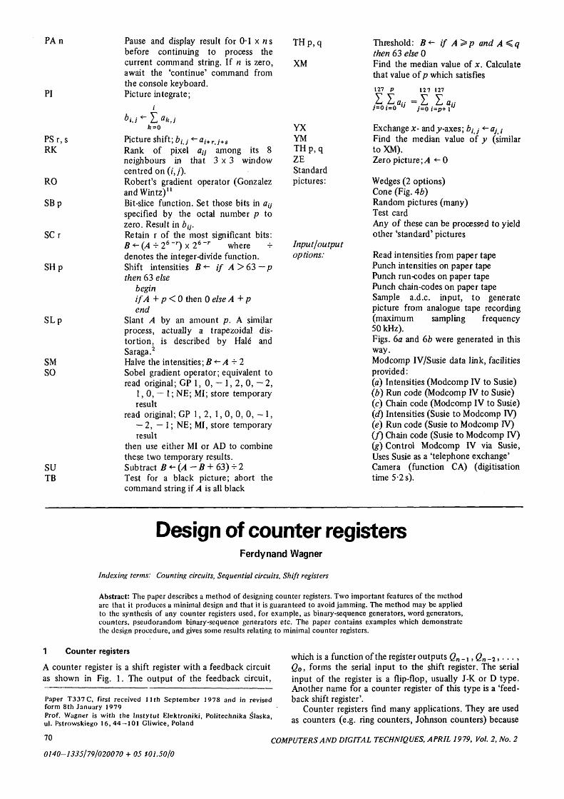
1 Counter registers
A counter register is a shift register with a feedback circuitas shown in Fig. 1. The output of the feedback circuit,
Paper T337C, first received 11th September 1978 and in revisedform 8th January 1979Prof. Wagner is with the Instytut Elektroniki, Politechnika Slaska,ul. Pstrowskiego 16,44 — 101 Gliwice, Poland
which is a function of the register outputs Qn _,, Qn _ 2 , . . . ,Qo, forms the serial input to the shift register. The serialinput of the register is a flip-flop, usually J-K or D type.Another name for a counter register of this type is a 'feed-back shift register'.
Counter registers find many applications. They are usedas counters (e.g. ring counters, Johnson counters) because
70
0140-1335/79/020070 + 05 $01.50/0
COMPUTERS AND DIGITAL TECHNIQUES, APRIL 1979, Vol. 2, No. 2