Embed Size (px)
Citation preview

Interaction in Optimisation Problems: A Case Study in Truss Design
Simon de Timary & Sean Hanna University College London, London
This paper is a preliminary study to explore the benefits of user interaction in topology optimisation by attempting to support two distinct claims: the first claim states that there exist similarly optimal, yet visually different designs based on the exact same parameters. The second one supports that accurately predicting the outcome can guide the program to faster convergence by skipping intermediary steps. For the purpose of this research a program based on Sigmund's 99-line MATLAB code for topology optimisation [1] was developed to implement real-time interaction. The programming language chosen was Java® for its flexibility and ease of scripting as well as its global efficiency [2]. Both claims were tested through two distinct sets of experiments. The first one modified the designs by adding and/or removing material and proved the existence of similarly optimal yet different designs. The second one explored the use of pseudo-filters to simulate intuition and managed significant decreases in the amount of iterations necessary for convergence. This second experiment also produced slightly stiffer designs. Both experiments led to the conclusion that user interaction, when used responsibly, helps topology optimisation in generating creativity and in speeding the process.
Introduction
The present work explores the benefits of human interaction in a deterministic process such as topology optimisation. The benefits of real-time human input are explored through two different statements. The first claim – responding the need for several design options1 – states that, since the solution to the problem of minimising the objective function is a local minimum [3], there should exist similarly optimal, yet visually different 1 In order to be able to make a choice based on aesthetical reasons.

2 S. de Timary and S. Hanna
designs based on the same parameters. The second claim – addressing the time constraints of design practices – supports that accurately predicting the final design can guide the program to faster convergence by skipping intermediary steps.
In order to assess both statements, two sets of experiments were conducted. The first one modified the designs by adding and/or removing material and the results showed the existence of similarly optimal yet different designs. The second one explored the use of pseudo-filters to simulate intuition and managed significant decreases in the amount of iterations necessary for convergence. Furthermore, 94% of the designs produced in this second experiment had greater stiffness than those produced by standard methods.
Before getting any further, it is important to notice that the practical
context of this research would involve an understanding of the degree to which the solutions resulting from user interaction compare to the theoretical optima (or as found by unaided gradient descent). As with any optimisation technique, there is potentially more research to be done to understand this with respect to various levels of complexity or specific problem domains. More specifically, two phenomena are relevant here: both the optimisation method itself and the nature of how a user’s intuition might lead them to make changes based on their expertise. In this paper, we focus on the former, and so the rules adopted to stand in for real user interaction are used so that the experiments can be controlled. Further work on the nature of real human learning processes and intuition about structures would be a useful further addition.
For the purposes of this research, a topology optimisation tool based on Sigmund's 99-line MATLAB code for topology optimisation [1] was implemented to enable real-time user-interaction. The program is a classical topology optimisation in the sense of material distribution [4]. The design is iteratively adapted to respond the displacements provided by a finite elements analysis until convergence is reached. This process is thus deterministic in that it will always produce the same design when run with the same parameters. This program is still in its developing phase and should, in its present state, mainly be considered as an education tool.
The first part of this paper will be dedicated to a brief explanation of the finite element method, a short review of the theoretical background constructed over the last twenty years by the leading authors in topology optimisation's field and a presentation of the used algorithm’s structure. The second part will describe more thoroughly the research question and

Interaction in Optimisation Problems 3
the two claims developed to answer it. The fourth part will describe the methods used to generate and analyse the results. These will then be presented and discussed. Finally, will be introduced the limitations of this study along with suggestions for future researches and the conclusion.
Theoretical background
Finite Element Method
The finite element method is a calculation technique based on discretising a structure or a continuous domain in a finite number of simple geometrical shapes which are called the finite elements [5]. This system greatly simplifies calculations since all of these elements can be calculated individually before the whole system is put together again. The stresses and strains are calculated locally at the nodes from the potential energy equation KU=F [2] where K is the stiffness matrix, F the force vector and U – the displacements vector – the unknown. This local equation can be extended to the whole system and thus enables the calculation of the displacements of every node in the system. Since the displacements are exact at the nodes [5], it implies that a larger amount of elements (a finer mesh) – therefore a larger amount of nodes – in the system, enables better accuracy of the calculated stresses and strains [5].
This calculation technique is perfectly well suited for the topology optimisation system provided by Sigmund [1], which is based on modifying the elements' density according to their nodal displacements [6]. Indeed, the density can be modified for each element individually and, as a result, the element stiffness matrix becomes the product of the original matrix by the density:
= .
Topology Optimisation
Amongst several existing types of shape optimisation problems, the present work uses that of shape design of optimal material distribution [4]. As Bendsøe [7] declared: “Shape optimization in a general setting requires the determination of the optimal spatial material distribution for given loads and boundary conditions”. The problem thus is, for each point in the domain Ω, whether there is material or not (amongst others: [4]; [7]). If this problem is solved using finite elements, the domain becomes that of the elements and each element is either solid or void ([7]; [8]).

4 S. de Timary and S. Hanna
Optimal shape design's aim is to minimise the objective function:
min(),
as described by many authors (e.g.: [9]), where is the displacement vector. In the present case, the objective function is the compliance, which is defined as “the work done by the external loads” [3]:
() = Ω+ .
Furthermore, since the compliance is equal to “twice the additive
inverse of the potential energy” ([10]: 206) and to the inverse of the stiffness, minimising the compliance can be considered as maximising the stiffness [3]. One can thus express the objective function through the energy bilinear form [4]:
(, ) = ().
s.t.: (, ) = !"#!"()# ()Ω [7],
where the elasticity tensor !" belongs to the set of admissible elasticity tensors $%&. In these terms, the goal of the optimal design is to find the optimal choice of elasticity tensor in $%& [4] or if finite elements are used to solve the equations, the optimal stiffness matrix .
Program presentation
The code used in this research was assembled from the following two codes, both available online. The first one is a translation in Java® of Sigmund’s 99-line MATLAB code for topology optimisation [1]. The second code is Nikishkov’s Programming the finite elements method in Java® [2]. While Sigmund’s code is self-sufficient in MATLAB, the matrix operations are not taken care of in Java and Nikishkov’s LDU (lower, diagonal, upper) solver was implemented.

Interaction in Optimisation Problems 5
The optimisation process is run on a rectangular beam (domain) which is then discretised in the desired amount of squared quadratic 4-node elements (Q4). These elements all have the same material properties (the same element stiffness matrix) and are associated with a density factor when the global stiffness matrix is assembled. At the first run of the algorithm each element in the global stiffness matrix has its density initialised to the target volume (e.g. 0.5). With this particular setup is then run a first finite elements analysis which returns the nodal displacements. The elements’ density is then adapted to match the displacements before filtering the sensitivities of the new density in order to make the design mesh-independent and checkerboard-free. Finally, if the maximal difference between the previous and current stiffness matrix is over a certain threshold (e.g. 0.001), the process starts again from the finite element analysis (Fig1).
Research Question
Topology optimisation has been extensively studied in the past twenty-five years and for more information on the mathematical concepts behind it, one can refer to the existing literature in the field. The aim of this paper is thus not to develop new techniques in topology optimisation but rather to study the opportunities offered by new computational resources in user interaction. To do so, the impact of user interaction as a means for design and efficiency was explored. The type of topology optimisation presented
Fig1. Diagram of the optimisation process of a domain of nelX * nelY
elements [11]

6 S. de Timary and S. Hanna
here relies on a finite element analysis coupled with a hill climbing approach, neither of which involves randomness. This process therefore leads consistently to the same results for the same parameters. This phenomenon might be unwanted when the program is used in a design practice that is likely to look for several different options. The time factor is also a crucial aspect and constraint of designing a project. In regard to these issues, the present research will try to assess whether user interaction can reduce computational time as well as generate various designs responding the same conditions. In order to explore the interrogations of this research question, two claims were developed.
- Claim 1
The first claim is related to the issue that topology optimisation is a deterministic process. Indeed, practices are likely to wish for several different designs produced on the same parameters and since the problem of minimising the compliance only gives local minima [3], one might wonder whether it would be possible to produce different designs that are similarly optimal. The claim is as follows. C1: There exist visually different designs, solutions to the same design problem, which have comparable compliances to the optimal shape produced by the program on its own. The way to supporting this claim is to try and produce different designs on the same boundary conditions and then compare their objective function (the compliance) with the originals.
- Claim 2
The second claim emerges from the fact that topology optimisation is an extremely time-consuming process. One might thus wonder whether these processes could be sped up by a user. The second assumption is as follows. C2: Accurately predicting the outcome guides the program to early convergence, skipping a large number of steps, thus reducing computational time. This claim will be assessed by filters mimicking intuition in such a simple way that real intuition should provide better results.

Interaction in Optimisation Problems 7
Methods
In order to assess the validity of both claims, two series of tests were conducted. Automated processes were chosen over real interactions for comparison and accuracy purposes as well as for resource constraints2. Five base cases with different loads, boundary conditions, proportions and mesh refinement were created. These cases were named: 4-corners, cantilever, MBB, Michell-1 and Michell-2. They can be seen in their final form in Figures 2 to 63.
The first wave of tests was trying to assess the validity of Claim 1 and their aim was to produce designs as different as possible from the originals. In order to do so, series of 'blind' tests were realised. These were gathered into three different experiments. While each experiment followed the same patterns, the first one solely added material, the second one strictly removed material and the third one was a combination of both4. Six patterns were drawn once onto
the designs at different times with a geometric progression in the loop where the change was made (1, 2, 4, 8, 16, 32 and 64). These patterns can
2 See the parts on future improvements and limitations for more information on resource constraints. 3 Triangles represent hinges; bars represent boundary conditions for a whole side and the thin arrows under those bars show the direction in which displacements are blocked; thick arrows represent a downwards unitary force. 4 It might useful to note that the intervention of a user mid-way through the optimisation
process is a special case of changing the initial start point for optimisation.
Fig2. 4-corners
Fig5. Michell-1
Fig3. Cantilever
Fig4. MBB-beam

8 S. de Timary and S. Hanna
be observed in Figures 7 to 12. These three experiments comprised a total of 528 tests amongst which 231 visually different designs (44% of the sample) were selected arbitrarily by the researcher. However, one must note that, even though 231
tests led to different designs, there were not 231 different designs produced. Most of them were similar to each other and only 28 genuinely different families of designs were produced. The comparisons in the results analysis section were made on one example per family. These can be observed in the appendix.
The second series of tests simulated intuition through the use of two different pseudo-filters5 both based on the assumption that a user trying to help the program would remove the excess material where it is obvious that there will not be any at the end of the run and add up material on the structural members. This type of filter could be considered as an explicit penalty on the densities along with SIMP [8, 9]. Thirty-two tests were conducted for the second hypothesis (16 per filter). The first filter was a simple threshold that removed the weakest elements (under 0.2 of density) and reinforced the strongest ones (over 0.8 of density). The second filter was looping through the density matrix and retrieved the weakest and strongest elements and changed them to the lower limit (0.001 to avoid a
singular stiffness matrix [12]) and to the upper limit . This filter was launched only after the fourth loop when enough elements had been able to evolve towards extreme values. The filter started by selecting the 10% most extreme values on either side and this amount increased by 1% per loop until it reached the lowest value between 35% and the target volume.
5 These pseudo-filters have a role similar to actual filters but work with threshold values rather than neighbouring cells.
Fig7. Pattern 1 (Test 1, Exp. 3) Fig8. Pattern 2 (Test 2, Exp. 3)
Fig6. Michell-2

Interaction in Optimisation Problems 9
Every test of every experiment returned the last density matrix, and a
record of the evolution of compliance and change through the loops. The change in density (deviation) from the original design was calculated by the following formula:
∑ ( −
*&+&( ∗ 100/01
2
where
and *&+& are the density matrix of the original and
modified designs respectively and 2 is the number of elements. Similarly, the change in compliance and iterations had to be calculated the following way:
34 − 4*&+&54 ∗ 100
where X is the value being compared.
Fig9. Pattern 3 (Test 3, Exp. 3) Fig10. Pattern 4 (Test 4, Exp. 3)
Fig11. Pattern 5 (Test 6, Exp. 2) Fig12. Pattern 6 (Test 4, Exp. 3)

10 S. de Timary and S. Hanna
Results analysis and discussion
Claim 1: There exist visually different designs, solutions to the same design problem, which have comparable compliances to the optimal shape produced by the program on its own.
The first statement tries to assess whether structures produced from the same boundary conditions and contrived to be different could have a similar compliance. In order to do so, the first part of the experiments was trying to generate visually different solutions by applying a series of blind tests to the structures at different time intervals. Out of 528 tests, 231 led to visually different designs (~44%). The first and second experiments were both made of 198 tests and led respectively to 69 (~35%) and 92 different designs (~46%). The third experiment comprised 132 tests and led to 70 significantly different results (~53%). One must note though that the last two experiments only led to 168 (85%) and 117 (89%) designs. The remaining tests crashed and only produced a fully black domain. This shows that subtraction (and a combination of both addition and subtraction) of material is more efficient in achieving change than simple addition. This can be explained by the fact that removing material allows for better redistribution of material. The volume must stay constant at the end of the process and this means that the removed material must be redistributed in the design and, since removed material cannot sustain any stresses, these need to be displaced elsewhere on the design. Material will not be redistributed where it was removed but where the stresses and displacements have shifted. Yet, it is also a more destructive process. Indeed, when the alterations are made late in the process and slash through the structural elements, this leads to singularities in the stiffness matrix and the result is a black beam. On the other hand, when simple addition is performed, unless there is significant room for change (blurry design, homogeneous material distribution) the changes cannot be taken into consideration since the filtering of sensitivities takes it as a numerical instability (i.e. checkerboard effect6). Moreover, on the contrary of subtractive modifications, material must be removed and usually the added material is removed immediately, as the displacements have not shifted and the original structure is still optimal in regard to those.
6 Defined as “areas where the density jumps from 0 to 1 between neighbouring elements” (Pedersen et al., 2006: 1), the checkerboard patterns are a common numerical instability that occurs particularly when using Q4 elements [13].

Interaction in Optimisation Problems 11
Most of the 28 different designs achieved quite a significant change in material distribution (over 90% of the sample achieve more than 10% of change). Furthermore, as can be seen on Fig13, 75% of the sample achieved a compliance close to the original compliance (less than 5% of difference or stiffer solutions). An obvious result was that minimal change in the structure leads to minimal change in the compliance (all tests under 10% of change led to a change in compliance of less than 1%). Another result is that after a certain point of change, the resulting compliance is not even remotely close to optimality (this may be observed on Fig7, zone 2). The limit seems to lie at about 25% of change (red vertical line) after which the increase in compliance goes over 20% almost systematically. This leads to the conclusion that while it is possible to achieve significant changes in topology and still keep the same or better structural quality, if the design is too different from that provided by the program alone, the structure is no longer optimal. However, finding the change limit after which the design is no longer optimal would require further researches since only the Michell topologies showed such an increase in compliance.
From these results, claim 1 may be confirmed since it is clearly possible to obtain significantly different topologies (>10% change) that have comparable or better stiffness. All results in zone 1 (Fig13) qualify for these criteria, since they produced over 10% change and have less than 5% increase in compliance. Out of the 28 families, 17 (61%) are in zone 1 and out of the 11 remaining, three produced marginally better results without accomplishing significant change and one had a spectacular percentage of change and stiffness improvement (circled 1 on Fig137). There is also a limit to change that the program can accomplish and, if the program manages to cross that limit, it leads to non-optimal designs. Crossing this limit should thus be avoided. No specific method was developed to avoid crossing this limit; however, good sense (i.e. not isolating the structure from its supports) is usually enough to prevent high rises in the compliance. One might conclude that user interaction can provide valuable help for topology optimisation but is at the user's discretion and not all results provided are optimal.
7 This case is the 4-corners case for which the solution provided by the program is far from the optimal one. It is only a marginal result and should thus be disregarded.

12 S. de Timary and S. Hanna
Claim 2: Accurately predicting the outcome guides the program to early convergence, skipping a large number of steps, thus reducing computational time.
The second statement claims that user interaction would speed up the optimisation process by removing intermediary steps. The results analysis confirmed this statement. Indeed, using pseudo-filters to mimic intuition produced results in a much shorter amount of iterations. However, what is suggested in this research is not that user interaction is the only way to reduce the amount of iterations and therefore improve the speed factor of an optimisation process. Indeed, it is important to first optimise the speed factor of the programme computationally. As an example of such speed improvement, Andreassen et al. reworked Sigmund’s 99 line MATLAB code to an 88 line code that showed a speed improvement factor of 100 and enabled the calculations of highly dense meshes [14]. Tovar et al. also generated a new technique relying on hybrid cellular automata that showed a considerable reduction in the amount of iterations [15, 16]. Only then, when using the most efficient structural optimisation technique available, one could add user interaction to it and enable for the designers’ intuition to guide the programme to faster convergence, therefore further reducing the amount of iterations. The first simulation of intuition, which was a poor simulation in regard to obtaining smooth looking results, provided astounding results with decreases in the number of iterations of up to 54%
Fig13. Compliance in relation to deviation
Evolution of compliance in relation to deviation

Interaction in Optimisation Problems 13
(Michell 2, dense). As a result, convergence is indeed sped up by modifying the densities already clearly solid or void. Intermediary steps are thus removed by the user. These tests also resulted in lower compliance. This can mostly be explained by the fact that the lowest densities (that have very little contribution to the stiffness by their low value and the penalisation scheme or SIMP [13]) are set to , which allows for more
material to be added to the structural parts, thus enhancing the stiffness. The final design is closer to a 0-1 design while keeping the same volume and is thus logically stiffer.
The use of simple pseudo-filters to simulate a simplified intuition based on the idea that users will try to get rid of intermediate densities by erasing the weakest elements and strengthening the strongest proved successful. Both filters showed a sharp decrease in the number of iterations as well as a relative decrease in the compliance. Several tests reached savings in iterations of over 60%. All tests were very receptive to the filters apart from the first Michell topology with a coarse mesh which was already at a very low amount of iterations. This process turned out to be very efficient by itself and could not be improved by these filters. All the others were very receptive and out of the 32 conducted experiments, only 5 of them (amongst which the two Michell-1 coarse experiments) did not lead to a decrease in the amount of iterations (84% of the experiments conducted to a positive result). This can easily be observed in Fig14. The mean decrease in the number of iterations was 28.1%.
1 2 3 4 5
-80
-60
-40
-20
0
20
40
60
80
100
1) 4-corners 2) cantilever 3) MBB 4) michell-1 5) michell-2
Savings in iterations (%)
EXP1 LONG coarse
EXP1 SHORT coarse
EXP2 LONG coarse
EXP2 SHORT coarse
EXP1 LONG dense
EXP1 SHORT dense
EXP2 LONG dense
EXP2 SHORT dense
Fig14. Savings in iterations

14 S. de Timary and S. Hanna
Moreover, along with a decrease in the number of iterations, the filters led to a decrease in the compliance (a higher stiffness). While the decrease in compliance was not as impressive as that of the iterations, it was still noticeable. Indeed, the results reached a decrease of up to 15% with the first Michell truss in the second experiment and even reached 23% in the long and dense 4-corners structure8. Only two examples achieved a higher compliance (an increase of less than 3%) out of the 32 experiments (94% positive results). These results can be observed on Fig15. The mean decrease in compliance was 5%.
In order to verify the obtained results, the material distribution's
deviation between the original design and the filtered ones was analysed. Some of these results were rather different. The 4-corners example was quoted in previous developments. The cantilever beam9, long and dense of the second experience had a deviation of 10% and was visually very different (see Figures 16 and 17). As can be observed, the modified cantilever beam would be easier to predict and seems more natural. However, the lines are not as smooth and this phenomenon could be observed on all filtered structures (these filters somehow seemed to
8 This result corresponds to the one mentioned in the previous footnote. 9 The reason the original design is unsymmetrical is the slight upward shift in the concentrated load. Indeed, it is not applied on the middle node but on the one above it.
Fig15. Decrease in compliance

Interaction in Optimisation Problems 15
counteract the blurring effect of the filtering of sensitivities). This effect might be responsible for the decrease in compliance.
Fig16. Original cantilever (dense mesh)
Fig17. Resulting cantilever, exp. 2
The 4-corners, cantilever and Michell-2 structures all had a deviation of
±10%. However, the results were extremely close for the short examples both visually and quantitatively. These cases resulted in smaller decrease in the compliance and accounted for some of the negative results both in compliance and in iterations. As can be observed on Fig18, the deviation generally stayed under 10%, one can thus conclude that these structures stayed globally the same with a better compliance and a lesser amount of iterations. As for the structures that deviated by more than 10%, they were all slightly stiffer and thus contribute to demonstrating claim 1 as well. These results clearly indicate that predicting the outcome (even poorly such as was presented here), helps the program drastically.
1 2 3 4 5
0
5
10
15
20
25
30
35
40
45
50
1) 4-corners 2) cantilever 3) MBB 4) michell-1 5) michell-2
Deviation (%)
EXP1 LONG coarse
EXP1 SHORT coarse
EXP2 LONG coarse
EXP2 SHORT coarse
EXP1 LONG dense
EXP1 SHORT dense
EXP2 LONG dense
EXP2 SHORT dense
Fig18. Percentage of change

16 S. de Timary and S. Hanna
To conclude the part on the results analysis, one can see that both claims seem to hold and that real-time user interaction may be considered useful in a topology optimisation process when it is used to help or find other designs. However, this process can lead to non-optimal designs when the user is not careful and can also vastly increase the number of steps.
Designers should hence always be cautious and make sure the modified topologies provided are optimal. However, a good knowledge of the program truly guides intuition both in generating valid different designs and in driving the process to faster convergence. Further research would enable to determine the threshold to which change leads to non-optimal designs, inducing “rules of thumb” and threshold values for the compliance. Furthermore, despite the fact that one might need to run the program on its own in order to assess the validity of their own solutions, most of the time the program’s use will take place in a large design process and will usually be the very first run before alterations are made.
Finally, one should add that real interaction would have further reduced the amount of iterations. Indeed, using the filters at every loop often prevented the programme from reaching convergence.
Limitations
The presented results, discussions and interpretations have to be considered under some limitations. Firstly, in the experiments linked to the first statement, not only was the selection of visually different designs made arbitrarily, but so was the selection of the different families. This inevitably resulted in information losses. Due to time and hardware constraints, only a limited amount of tests were conducted and the mesh refinement was limited to a rather coarse mesh. A more extensive range of boundary conditions could have revealed different results and a more refined mesh would have enabled better interaction and a larger deviation of the modified designs from the untouched ones. Indeed, coarse meshes tend to be too stable.
Further improvements could be made to the code in order to make it more user-friendly: incorporate it as a plug-in into a CAD environment in which the designer could simply draw the boundary conditions, select the number of elements in one direction and then generate the sequence and interact with it; play it on a touch-screen, etc. Other improvements should be made in order to enable more possibilities of the code (i.e. enable 3D,

Interaction in Optimisation Problems 17
variable boundary conditions, variable forces, take into account structural instabilities such as torsion or buckling, etc).
Using designers and structural engineers unfamiliar with the design in
the process of testing would have broadened the range of results and made possible input of real intuition. For instance, the rules used in these experiments were much too simple to accurately simulate user interaction and if it really were possible to simulate user interaction, then user interaction would not improve what can be generated by a computer. The real interest lies in genuine human input. However, the aim of this paper was to determine whether user interaction could improve the process of structural optimisation, therefore human learning processes were not taken into account. Future research should thus include tests with designers and engineers, and assessment of genuine intuition in order to demonstrate that this would lead to even better results. Tests should also be conducted to determine the limit of change at which the modified design becomes non-optimal.
Finally, this paper and the supporting tool should only be considered as
preliminary work in interaction for structural optimisation. The program is intended as a starting point in the reflexion on structural design and should be followed by further design and more extended structural calculations taking into account material properties, uncertainty, connexions and national building codes. Moreover, the programme should be optimised in regard to speed and robustness issues. Only then could it be considered as a real design tool. Until then, it should mostly be considered as a teaching tool intended for beginning designers to grasp the concepts behind structural optimisation and develop their intuition in the field. This research is not in itself a revolution in design but merely suggests leads as to how structural optimisation should evolve in the future.
Conclusion
The present research tried to assess whether the introduction of human interaction could help make topology optimisation a better design tool for structural designers. Two claims were developed to investigate this and were both verified in the present work. It was demonstrated that designs can be bent towards different solutions and still be optimal. This result implies that designers should be able to produce a wide range of optimal designs that fulfil their requirements so they can choose the “best one” on

18 S. de Timary and S. Hanna
aesthetic criteria. This study also showed that predicting the final design significantly reduces computational times. This would be useful when trying to meet the time constraints of a design process.
However, if this program is not used properly, it can lead to designs far from optimal and is also liable to crash without returning any design at all. Designers should thus be conscientious when interacting with a structural optimisation software and pay attention not to break the structure without providing it with an alternative. They should also ensure that the structure is indeed optimal.
Hence, a robust and fully functional version of this program would be a useful tool to incorporate at the beginning of any design process. It provides a wide range of optimal designs and leads the designers in several different directions. It can also be used as an education tool to develop starting designers’ intuition in topology optimisation as well as in general structural design.
Finally, the solving of complex topology optimisation problems tends to exclude radically any human input and the process usually ends up by an unsupervised computer calculating a solution overnight. If human responsibilities are limited to feeding a program with boundary conditions before even that program is launched, then to what extent can topology optimisation be considered a part of design? It is hoped that this research and the program that supports it will contribute to a greater integration of intuition and designer creativity in the use of topology optimisation.
References
1. SIGMUND, O. (2001). A 99 line topology optimization code written in MATLAB, Structural and Multidisciplinary Optimization, 21: 120-127.
2. NIKISHKOV, G. (2010). Programming Finite Elements in Java, London, Springer.
3. REISS, R. (1976). Optimal Compliance Criterion for Axisymmetric Solid Plates, International Journal of Solids and Structures, 12: 319-329.
4. BENDSØE, M. P. & KIKUCHI, N. (1988). Generating Optimal Topologies In Structural Design Using A Homogenization Method, Computer Methods In Applied Mechanics And Engineering, 71: 197-224.
5. WARZEE, G. (2010), Méthode des éléments finis (structures), 7th edition, Brussels, Presses Universitaires de Bruxelles.
6. BENDSØE, M. P. & SIGMUND, O. (2003) Topology Optimization. Theory, Methods and Applications. Berlin, Springer-Verlag.
7. BENDSØE, M. P. (1989). Optimal shape design as a material distribution problem, Structural Optimization, 1: 193-202.

Interaction in Optimisation Problems 19
8. ROZVANY, G. I. N. (2001). Aims, scope, methods, history and unified
terminology of computer-aided topology optimization in structural
mechanics, Structural and Multidisciplinary Optimization, 21: 90-108. 9. LISZKA, T. & OSTOJA-STARZEWSKI, M. (2003). Effects of
microscale material randomness on the attainment of optimal structural
shapes, Structural and Multidisciplinary Optimization, 25: 1-10. 10. CHANDRASHEKHAR, S. J. & HABERB, R. B. (1996). Stability of
finite element models for distributed-parameter optimization and
topology design, Computer Methods in Applied Mechanics and
Engineering, 130: 203-226. 11. dE TIMARY, S. (2011 b), Exploring Interaction as an Optimisation Tool,
Research Dissertation, Adaptive Architecture & Computation, University
College London. 12. BRUNS, T. E. (2005). A reevaluation of the SIMP method with filtering
and an alternative formulation for solid-void topology optimization,
Structural and Multidisciplinary Optimization, 30: 428-436. 13. SIGMUND, O. (2007). Morphology-based black and white filters for
topology optimization, Structural and Multidisciplinary Optimization, 33:
401-424. 14. ANDREASSEN, E., CLAUSEN, A., SCHEVENELS, M., LAZAROV, B.
& S., SIGMUND, O. (2011). Efficient topology optimization in
MATLAB using 88 lines of code, Structural and Multidisciplinary
Optimization, 43: 1-16. 15. TOVAR, A., WILSON, I. Q., PATEL, N. M. & RENAUD, J. E. (2005),
Hybrid cellular automata with local control rules: a new approach to
topology optimization inspired by bone functional adaptation, 6th
World
Congress of Structural and Multidisciplinary Optimization, 30 May – 03
June 2005, Rio de Janeiro, Brazil, pp. 1-11. 16. TOVAR, A., PATEL, N. M., NIEBUR, G. L., SEN, M. & RENAUD, J. E.
(2006) Topology Optimization Using a Hybrid Cellular Automaton
Method with Local Control Rules, Journal of Mechanical Design, 128:
1205 - 1216.
Appendix: design families
Fig19. 4-corners, family 1, deviation 6.2%, compliance +0.13%
Fig20. 4-corners, fam. 2, dev.
47.3%, comp. -25.8%
20 S. de Timary and S. Hanna
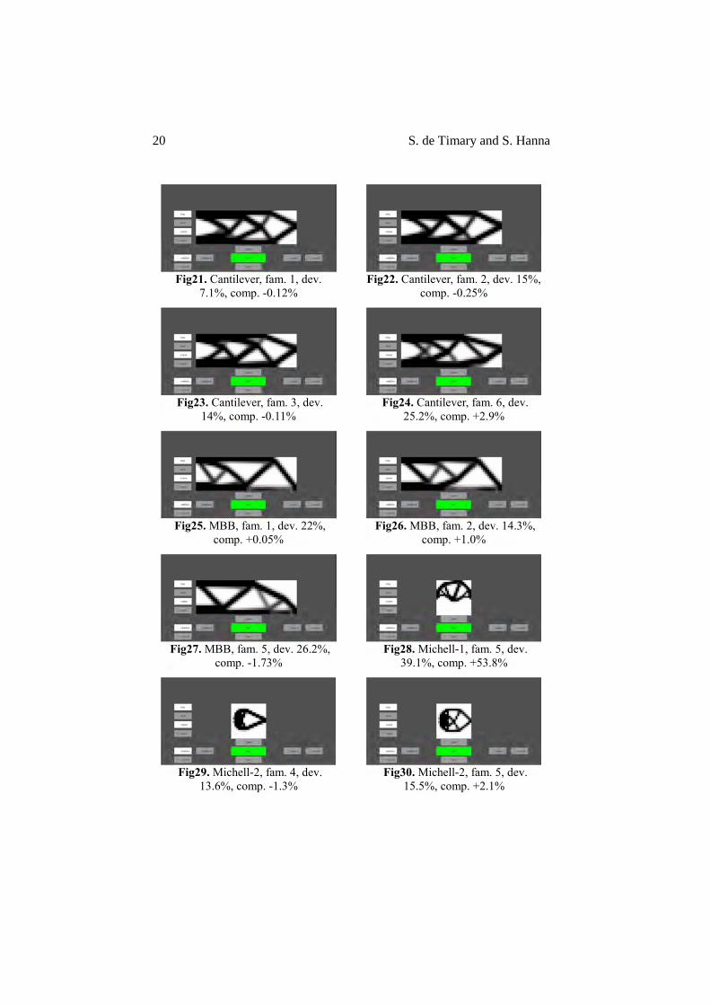
Fig21. Cantilever, fam. 1, dev.
7.1%, comp. -0.12%
Fig22. Cantilever, fam. 2, dev. 15%,
comp. -0.25%
Fig23. Cantilever, fam. 3, dev.
14%, comp. -0.11% Fig24. Cantilever, fam. 6, dev.
25.2%, comp. +2.9%
Fig25. MBB, fam. 1, dev. 22%,
comp. +0.05%
Fig26. MBB, fam. 2, dev. 14.3%,
comp. +1.0%
Fig27. MBB, fam. 5, dev. 26.2%,
comp. -1.73%
Fig28. Michell-1, fam. 5, dev.
39.1%, comp. +53.8%
Fig29. Michell-2, fam. 4, dev.
13.6%, comp. -1.3%
Fig30. Michell-2, fam. 5, dev.
15.5%, comp. +2.1%