Embed Size (px)
Citation preview

Interaction and input devices
Ruth Aylett
Contents
Interaction Tracking
– What is available Devices
– Gloves, 6 DOF mouse, WiiMote, Kinect

Why is it important?
Interaction is basic to VEs – We defined them as ‘interactive in real-time’
No interaction => NOT a VE Ideal interaction:
– Very low latency - i.e fast – Multi-modal – Unencumbered – Intuitive
Technology falls well short of this of course

Interaction types
Navigation – Staying on the ground? – Walking v flying
• Depends on size of model wrt display system • Degree of immersion
Interaction with objects: selection, manipulation – Depends on the object and interaction – Select, lift, rotate, throw, steer, hit
Interaction with other users – Gesture

Navigation
Move between locations: simplest form of interaction – Explore the environment; look at it
Ambiguous term: – Path integration/dead reckoning – Wayfinding – Locomotion

Path integration/dead reckoning
From known coordinates: – How far have I come?
• Distance/rotation
– So where am I now? – Continuous update cycle
• Compare with desired end coordinates

Wayfinding
What route from here to there? – Requires spatial knowledge/understanding
• Of landmarks, routes
A natural approach? – Line-of-sight; Virtual signage; virtual map
• If used for training for example
– Sound? Floating arrow? Head-up display? Follow a ‘guide’?
– Naturalism works better for direction than distance

Process
Orientation – Where am I wrt to nearby objects and the target
location?
Route Decision – Choose route that does go to destination.
Route Monitoring – Check on the correct route and going in the right
direction. Destination Recognition
– Are we there? Or at least close?

Locomotion
Teleportation Scene In Hand Eye In Hand Flying Vehicle Manipulation methods as locomotion Leaning (relative vs absolute) Speech driven Device Specific (driving)

Movement
Physical locomotion – User physically moves within tracker coverage
area – Frame of reference for interaction is own body – Real-world orientation cues
Virtual locomotion – Virtual world moves/rotates around user – Frame of reference is display device/physical
frame – Can cause disorientation quicker then physical
motion

Locomotion styles Unconstrained
– Tracker orientation determines direction of travel • Users may roll or go up/down as they move forward-left-right-
back • May disorient new users; difficult to control
– Users travel through objects;no collision detection • High-speed navigation,needs high frame rate
Constrained – Restricts locomotion to plane/direction (no roll is common)
• Sets some speed/acceleration limits (may take frame rate into account)
– Collision detection • adds computational load to application • Better orientation cues • Enhances solidity & realism of environment

Selection
Direct manipulation – Intuitive; can be tiring; or infeasible
Ray-casting – Laser pointer; less tiring – May be imprecise: small objects, distances, tracker
noise – Manipulation?
Cone-casting (spotlight) – Easier than ray-casting – May select multiple objects – Also manipulation issue

Tracking the human body
Large displays require position and orientation of viewer’s body to be tracked – tracking information fed to runtime system as input signal.
Most commonly tracked is head but sometimes also hands, arms, legs, eyes etc. – Head tracking used to update virtual
viewpoint orientations.
Body tracking needed for lifelike interaction with objects and creatures. – say user wishes to wave at another person
in the VE: their real-world motions can be tracked and replicated in the VE.

Virtual Tennis
Movie Virtual Tennis
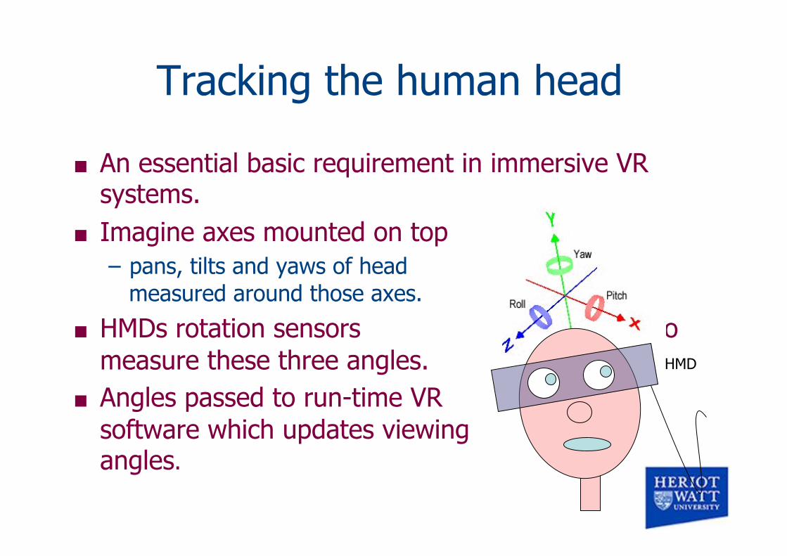
Tracking the human head
An essential basic requirement in immersive VR systems.
Imagine axes mounted on top of your head – pans, tilts and yaws of head
measured around those axes.
HMDs rotation sensors to measure these three angles.
Angles passed to run-time VR software which updates viewing angles.
HMD

Tracking devices
Many tracking devices and systems developed over the years – some aimed specifically at VR systems – others borrowed from other areas.
Some systems are portable and cheap - some require permanent installations in large rooms and are very expensive indeed. – Trackers can be magnetic, electro-magnetic, acoustic, inertial,
optical, or mechanical.

Mechanical trackers
Mechanical linkage system – arm-like structure of several joint, one end fixed, the
other free to move with the user.
Measure position and angular orientation of free end – by measuring angles at each joint and
factoring in length of each segment.
Fake Space BOOM (right)

Mechanical Tracking Advantages Simple sensors, no need for transmitter/receiver low-cost device very low latency High positional accuracy Disadvantages The user is tethered Lots of inertia Typically small working volume Mechanical parts wear out

Exoskeletons For bodies or parts of bodies
– Derived from assistive technology • Working backwards

Electro-magnetic trackers
transmitter generates electromagnetic signals
received by a receiver (or sensor). Signal strength used to determine
absolute position and orientation of receiver relative to transmitter.
Example: Polhemus FASTRAK
FASTRAK electro-magnetic sensor from Polhemus – accurately computes the position and orientation of tiny receiver
as it moves through space.
Dynamic, real time six degree-of-freedom measurement of position (X, Y, and Z) and orientation (yaw, pitch, and roll) – RS-232 signal updated at 120 records/sec.
Transmitter constantly puts out a weak magnetic field. – passive receiver generates an electric signal as it is moved
through the field.
– Polhemus' processing electronics then amplify and analyse this signal to determine the real-world position and orientation of the receiver relative to the transmitter.

Polhemus FASTRAK system
Polhemous trackers well proven and widely used since the very early 1990’s.
The FASTRAK system shown here has one receiver and one transmitter.
System expanded by adding up to three more receivers – can attach receivers to
different parts of body – log data for gait and limb
analysis or computer animation.

Electromagnetic Tracking Polhemus

Electromagnetic Tracking Advantages Small receivers Reasonably cheap Line-of-sight (LOS) not required Disadvantages Accuracy diminishes with distance Not very large working volume High latency due to filtering Transmitter/receiver required

Electro-magnetic interference
Major problem of electro-magnetic trackers – magnetic fields easily affected by the surrounding environment.
Large metal objects produce eddy currents in the presence of the magnetic fields – These can interfere and distort the original signal causing
inaccurate measurements. – same effect appears near electric currents, such as in cabling – also ferromagnetic materials – Also electromagnetic sources such as computer monitors.
Ferromagnetic and/or metal surfaces cause field distortion

Ultrasonic trackers
Two main components – transmitter generating an ultrasound signal – receiver detecting the signal.
Distance is calculated by measuring time-of-flight of ultrasonic pulse. – Three transmitters and receivers
needed to calculate full 3D position and orientation.
Ultrasonic tracking used by Logitech Head Tracker (shown) and 3D mouse.

Acoustic Tracking
Advantages Well known transducers (mics), lightweight Low cost device Disadvantages Line-of-sigh (LOS) required Echoes Low accuracy (speed of sound in air varies) Transmitter/receiver required

Inertial tracking systems
Very popular (because cheap) – based on inertial gyro technology – Detects acceleration and thus can calculate velocity (since mass in
known) giving 3DoF – Newish example is the Intersense IS-300.
Can be coupled with ‘add-on’ ultrasonic system to give 6 DoF sensing – example of a hybrid technology tracker.
IS-300 can operate in metallic environments, – 6 DoF tracker operates only
in LoS of transmitter.
Other examples: Intersense Intertrax2 and the Ascension 3D-Bird.

Inertial Tracking Advantages Cheap Small size No transmitter/receiver required LOS not required Disadvantages Only 3 DOF on their own Drift Not accurate for slow movements

Optical tracking methods
Many different forms – Often use image processing and pattern recognition and matching – Much work outside of VR: numerous ideas suitable for tracking
object position and pose
For example fiducial mark detection – light sources or reflective
colour markers attached to object at important locations such as joints or extremities.
Easier for image processing algorithm to track in cluttered conditions.

How it is done
Optical tracking methods
Outside-in tracker – tracking apparatus is fixed – object to be tracked (e.g. the user) is viewed from the "outside".
Inside-out systems – take tracking measurements from the object to be tracked – for instance a camera can be mounted on the HMD – images analysed to produce pose and distance estimations based on
the position of fixed patterns within the environment.
Visible images or infra-red used. Many optical systems (but not all!) are one-offs, expensive
and require careful calibration procedures.

Motion Capture (Mo-cap)
Originally developed for gait analysis – Artificial limbs
Taken up by film/animation industry – Artificial actors (Titanic, LoR, etc..)
Can also be used in real-time

Infra-red cameras

Placement of markers
Depends on application – Body/face? – Occlusion issues?
Attaching markers – Body suit
• CMU database example
– Sweat bands etc
Also in processing software

Occlusion problems
Need a skeleton to find a lost marker that reappears – Included with camera sw
packages – But not always in data-
streaming mode
Optical Tracking
Advantages Can work over a large area. Inherently wireless Disadvantages LOS needed Transmitter/receiver required Expensive Requires computer vision technology

Speckled computing
Specks: small computing devices – Eventual aim: like
dust motes – Present size: a few
cm
Supports inside-out tracking – University of
Edinburgh

Unencumbered tracking
Depends on identifying head/hand on video – Early approach using blobs

Natural Interaction
Set of devices using sensing for unencumbered tracking and interaction – Kinect is the best known; now multiplying
Open NI consortium – Formed Nov 2010: includes Primesense
originators of Kinect

Open NI
See www.openni.org
Offers some device-independence

Kinect
Developed for xbox – Sold 8 million units in 60 days from Nov 2010 launch – Almost at once used for lots of other things – E.g http://kinecthacks.net/
Spec: • Colour and depth-sensing lenses • Voice microphone array • Tilt motor for sensor adjustment
– Field of View • Horiz: 57 degrees Vert: 43 degrees • Tilt range: ± 27 degrees • Depth sensor range: 1.2m - 3.5m

What is in it
Projects an IR grid – Affected by other IR sources (e.g. sunlight)
Built-in facial and voice recognition – simultaneously tracking of up to six people, – two active players with RT feature
extraction of 20 joints per player
Interfacing with Kinect
Originally unofficial use: Open NI – http://www.openni.org/
Driver Interface: – Two buffers
• rgb-data • depth-map (10bit
resolution)
After June 2011 official Windows 7 SDK

Kinect examples
Basic functions of Kinect
With OpenNI on Linux
Gesture recognition using FUBI • https://www.informatik.uni-augsburg.de/en/
chairs/hcm/projects/fubi/
Childs paint application

Interaction devices
Ruth Aylett
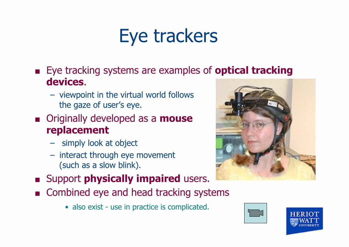
Eye trackers
Eye tracking systems are examples of optical tracking devices. – viewpoint in the virtual world follows
the gaze of user’s eye.
Originally developed as a mouse replacement – simply look at object – interact through eye movement
(such as a slow blink).
Support physically impaired users. Combined eye and head tracking systems
• also exist - use in practice is complicated.

Cybergloves and similar
Inherent in the folklore and hype of VR is the cyberglove - a wearable device that monitors the the position and orientation of hand and fingers.
The name CYBERGLOVE® is registered by Virtual Technologies Inc (VTi). – uses 18 or 22 patented
angular sensors for tracking the position of fingers and hand.
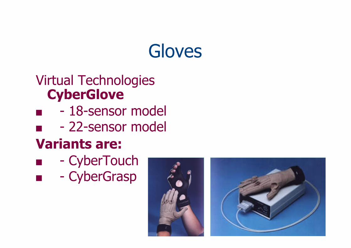
Gloves Virtual Technologies
CyberGlove - 18-sensor model - 22-sensor model Variants are: - CyberTouch - CyberGrasp
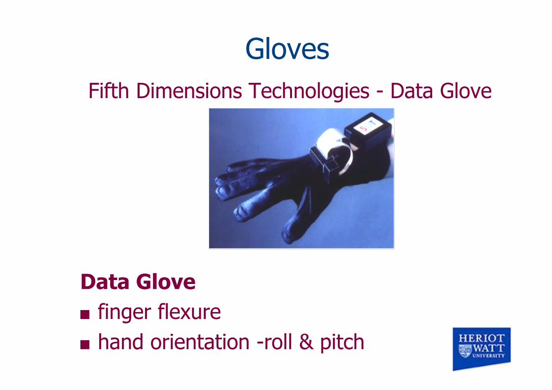
Gloves Fifth Dimensions Technologies - Data Glove
Data Glove finger flexure hand orientation -roll & pitch

Gloves
Fakespace - Pinch Glove Pinch Glove gesture recognition reliable low cost electrical sensors in
each fingertip contact among any 2 or more
digits

Mouse as input device in VR
Normal 2D mouse can be used (as in Octaga for example). – Need user selectable modes to switch between
DoF’s.
More sophisticated mice provide 3 or more DoF: these include the Spaceball (shown here) and Spacemouse.
Standard games joysticks or gamepads also used to give 2 or more DoF’s.

6 DOF “Mice”
3 translation DOF 3 rotation DOF

6 DOF “Mice” Spaceball
by Labtec
Spacemouse by DLR (Logitech - USA)

The WiiMote
3 accelerometers – Enough for 6 DOF – But will drift – Bluetooth connection
to 10m
Optical (IR) sensor – To 5m from sensor
bar – Triangulation from
ends of bar – Allows accurate
pointing Speaker
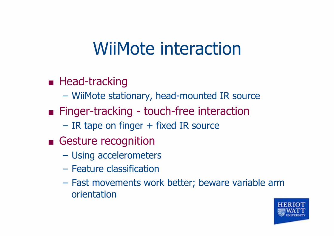
WiiMote interaction
Head-tracking – WiiMote stationary, head-mounted IR source
Finger-tracking - touch-free interaction – IR tape on finger + fixed IR source
Gesture recognition – Using accelerometers – Feature classification – Fast movements work better; beware variable arm
orientation

Software
Free libraries – WiiGLE
• http://mm-werkstatt.informatik.uni-augsburg.de/documents/WiiGLE/doku.php
• Provides a set of classifiers
– WiiGee • http://www.wiigee.org/index.html • Java-based, one classifier
Issues with Bluetooth stacks – Flakey implementations, especially Vista – BlueSoleil seems a good driver
• http://www.bluesoleil.com/


![PCPP: PRACTICAL CONCURRENT & PARALLEL …itu.dk/people/brabrand/PCPP/slides13.pdfClaus Brabrand, ITU, Denmark PRACTICAL CONCURRENT AND PARALLEL PROGRAMMING (PCPP) [ 3 ] Nov 28, 2014](https://img.dokumen.tips/doc/110x75/5ab1f9a47f8b9a1d168d3f43/pcpp-practical-concurrent-parallel-itudkpeoplebrabrandpcpp-brabrand-itu.jpg)


![Slides13 [Compatibility Mode]](https://img.dokumen.tips/doc/110x75/577d296f1a28ab4e1ea6c7a5/slides13-compatibility-mode.jpg)