So 400 X 100 = 40,000 volts of magnetic induction. I have no idea what that equates to, even-so I intend on finding out. When Transformed back into Electrical Flux it provides a very Large increase, becoming a Self Powered Energy Source.
Zane
As per Donald Lee Smith, 1 miligauss is equal is equal to 100 volts of magnet induction. This Illuma Storm will output about 400 Miligauss of magnetic induction.
Zane
This prospect excites me so much I must join in this hunt.
Zane
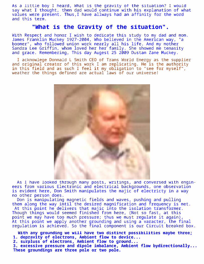
I acknowlege Donnald L Smith CEO of Trans World Energy as the supplier and original creator of this work I am replicating. He is the authority in this field and as such I feel it my obligation to "see for myself", weather the things defined are actual laws of our universe!
Zane
As a little boy I heard, What is the gravity of the situation? I would say what I thought, then dad would continue with his explanation of what values were present. Thus,I have allways had an affinity for the word and this term.
Zane
"What is the Gravity of the situation".
Zane
With Respect and honor I wish to dedicate this study to my dad and mom. James Franklin Muckey 1927-2004, Who believed in the American way, "a boomer", who followed union work nearly all his life. And my mother Sandra Lee Griffin, whom loved her her family. She showed me tenasity and grace. Remembering, This day Augest 25 2009 Dustan Zane Muckey.
Zane
As I have looked through many posts, writings, and conversed with engin- eers from various Electronic and electrical backgrounds, one observation is evident here, Don Smith manipulates the majic of electricty in a way no other person does. Don is manipulating magnetic fields and waves, pushing and pulling them along the way intil the desired magnification and frequency is met. At this point he delivers that majic into the isolation transformer. Though things would seemed finished from here, (Not so fast, at this point we may have too much pressure; thus we must regulate it again), At this point we apply another grounding and using a varacter, the final regulation is achieved. So the final component is our Circuit breaked box.
Zane
With any grounding we will have two distinct possibilities maybe three; 1. depravity of electrons, Ambient flow to device... 2. surpluss of electrons, Ambient flow to ground... 3. excessive pressure and dipole imbalance, Ambient flow bydirectionally... These groundings are three pole or two pole.
Zane
Intentions and Scope of Project
Zane
Zane
My goal is to produce A magnetic resonant air-core coil Induction system Capabable of producing its own power and subsequent output power. I am duplicating as my project a device Donnald Smith has so warmly given the plans openly to the world, as I assume is his gift to humanity. The First Objective is to aquire the necessary books, knowledge, equipment, and parts. Then to formulate a building process and assembly operation.
Zane
Zane
"Tesla's are the measurement of Magnetic Flux Density". One Weber and One Tesla are equal >>>>>>>>>>>>>
Zane
What understandings we need to duplicate these devices.
Zane
One gauss is equal to 100,000 volts.>>>>>>>>>>> One Oersted is equal to 50,000 volts. >>>>>>>>>>>>>> One Gamma is equal to 10 active Volts of electricty. >>>>>>>>> 24 gamma will equal 240 Volts.>>>>>>>>>>>>>>>>>>>>>>>>>
Zane
Both one henry and one farad = 1 Volt.
Zane
Standard unit = Tesla(T) Tesla through Gamma Relationship table
With this information we can deduct how many Teslas' are necessary to produce any quantity of electricty.
Zane
Don Smith's own intuition has led him to devoloped many working models, and too has compiled the electrical relationship understanding necessary to impiment these concepts.
Zane
As stated throughout this document you will notice this system is very small and simple. Few parts and few operations are involved collecting Ambient energy. Certain operational perameters are necessary to accomplish this task. This compilation, in total is the broad outline of operating systems. You will design a system with reguard to the output desired, "Your Isolation transformer size" is needed to determine the amount of electricty you gather. You must consider this as your final point, or target to have a complete operating electric generating system!
Zane
Compilation Notes:
Zane
Don states if we chase the magnetic component of electricty we will succeed in this research.
Zane
What we are doing in these operations is two distinctly different things than other researchers.
Zane
First: We are building up radio frequency to a level that induces free multiplication factors. First outcome; This value of multiplied frequency captures free electrons. These accumulated electrons are sent into the output transformer. Second: We are fluxing the ouput side of the Isolation transformer via inductance. The output side couriously has a highly deprived value of magnetic charge that needs to become ambient. Second outcome; We allow an earth grounding with a varistor to feed this magnetic induced output side, with the ambient energy from the earth grounding. This now becomes part of the electricty we are now supplying to our electrical service panel.
Zane
Each of the two operations cited above are the two components of electricty. One; Volts which is the multiplied frequency found in all Tesla coil applications, and other high voltage devices. These are more negative. And the other; Amperage which is less negative, 'the magnetcally charged earths surface". This inequality needs to regain ambient. "Because we are exposing this high voltage, "the more - charge", to "amperage, the Less - charge", through the Earth grounding and varister. These ampers naturally move to the oposite charge where they combine to the voltages we manipulated earlier....................
In coil systems, magnetic and amperage are one package. This suggests that electrons in their natural non-ionic state, exist as doublets. When pushed apart by agitation, one spins right (yielding Volts-potential electricity) and the other spins left (yielding Amperage-magnetic energy), one being more negative than the other. This further suggests that when they reunite, we have (Volts x Amps = Watts) useful electrical energy. Until now, this idea has been totally absent from the knowledge base. The previous definition of Amperage is therefore flawed.
Electron Related Energy
Left hand spin of electrons results in Electrical Energy and right hand spin results in Magnetic Energy. Impacted electrons emit visible Light and heat.
Useful Circuits, Suggestions for Building an Operational Unit
3 - 30
Zane
What is Electricty, and how is it Collected?
Zane
In coil systems, magnetic and amperage are one package. This suggests that electrons in their natural nonionic state, excist as doublets. When pushed apart by agitation, one spins right (yealding Volts-potential electricty) and the other spins left (yealding Amperage-magnetic energy), one being more negitive than the other. This further suggests that when they reunite, we have (Volts X Amps = Watts) useful electrical energy. Until now, this idea has been totally absent from the knowlege base. The previous deffinition of Amperage is therefore flawed.
Zane
Left hand spin of electrons results in Electrical Energy and right hand spin results in Magmetic Energy. Impacted electrons emit visible Light and heat.
Zane
As Don Smith has given this information and as the Establishment has chosen to ignore it. I say we individuals are called to prove and expose this knowlege.
Zane
As you know electricty in one fasion or another; Voltage is a given normally in all electrical applications, as too is amperage. For most of us we are not involved in electrical production. When we start from a magnetic impulse, we must measure that impulse to extrapilate the potential and amperage. For instance the plasma globe has no voltage output per se', it is a plasma, a magnetic value, gauss, or Tesla, etc. + or - measurment.
Zane
Electricty is a mystery!
Zane
For Voltage, the Correct Method of Measurment.. Use the inverse square law with an electrostatic volt meter. Measure at a safe distance, they are frequncy nonspacific.
Zane
For Amperage, the Correct Method of Measurment.. Use the inverse square law with hall-effect devices, measure from a safe distance. They are normally frequency nonspacific. The magnetic field they measure converts directly to amperage.
Zane
Derivation of Magnetic and Electric Power
Zane
Analogus relationships: 1. Potential power is present in a bar magnet as shown. 2. The source of these Electrons is from Solar Plasma, are non ionic and occupy all Free Space.
Zane
3. Resonant Electrical Coil Systems, (Tesla) are Analogus to the system observed in the Bar Magnet, (below).
Zane
They excist in Doublet Pairs, one being more negative than the other. The more negative has a Left Hand Spin, The less negative has a Right Hand Spin.
Zane
They are commonly obtained from Earth and air Groundings.
Zane
The Block Wall is located at the base of the L-2 Coil.
Zane
The Left Spin portion (Voltage Only) part of the Coil predominates. The right hand spin (magnetic-Amperage), portion is mostly absent.
Zane
<
Zane
Tesla Coil Geometry *
Zane
Electron-Volts
Zane
Curent-Ampers
Zane
Correct Method of Measurment.. Use the inverse square law with an electrostatic volt meter Measure at a safe distance, they are frequncy nonspacific.
Zane
Correct Method of Measurment.. Use the inverse square law with hall-effect devices, measure from a safe distance. They are normally frequency nonspacific The magnetic field they measure converts direct- ly to amperage.
Zane
This End has Greater Amperage Distributive Inductance at Maximum Induction-Henrys-Amperage Amperage has electrons spinning to the right.
Zane
Volts dominate if L-1 coil is far to the right. Volts and amperage is about equal when L-1 coil is centered.
Zane
This End has Greater Voltage Distributive Capcitance at maximum Capacitance-couloumbs- Voltage. Voltage has Electrons spinning to the Left
Zane
Volts represents the more negative and amperes the less negative, therefore the electrical charge of more negative must seek the charge of less negative to regain Ambient
Zane
As seen above flux lines are created by; One. Induction-henrys-amperage, Two. Capacitance-coulombs-volts, Both being defined; electrical energy. Don uses different means in various devices to get this energy, or he uses devices allready in production that make this magnetic flux. ie; plasma globes/tubes, or transformers of high frequency.
Zane
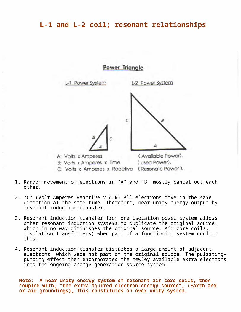
1. Random movement of electrons in "A" and "B" mostly cancel out each other. 2. "C" (Volt Amperes Reactive V.A.R) All electrons move in the same direction at the same time. Therefore, near unity energy output by resonant induction transfer. 3. Resonant induction transfer from one isolation power system allows other resonant induction systems to duplicate the original source, which in no way diminishes the original source. Air core coils, (Isolation Transformers) when part of a functioning system confirm this. 4. Resonant induction transfer disturbes a large amount of adjacent electrons which were not part of the original source. The pulsating- pumping effect then encorporates the newley available extra electrons into the ongoing energy generation source-system.
Zane
Note: A near unity energy system of resonant air core coils, then coupled with, "the extra aquired electron-energy source", (Earth and or air groundings), this constitutes an over unity system.
Zane
L-1 and L-2 coil; resonant relationships
Zane
Collection and transfer of electrical energy requires temporary storage, which occurs when capacitors and coils of a resonant circuit are cycled, off and on. The frequency at which the capacitor and coils are pumped determines the amount of electrical energy that moves onward.
Zane
Induced Electrical Energy System
Zane
The increase in flux lines present disturbes more electrons than previous, resulting in over-unity energy being present and available.
Zane
Resonant air core coil energy transfer.
Zane
The amount of energy transfered relates directly to the density of the lines of flux present. The kenetic energy formula is helpful in establishing the amount of energy present. This formula squares the velocity times mass. In the case of electrical energy, intencity of voltage and amperes times cycles per second replace velocity. "Note" The "acceleration" of voltage "E" and Amperage "I" which increase as non linier, then obeys the Law of Squares. Each unit of increase causes a squaring of the flux lines present. The amount of energy transfer caused by this increase in flux lines is demon- strated below.
Zane
My version and understanding of electrical energy transfer
Zane
As seen below, electrical energy is not a river per se' it is more like a hand shake. Irreguardless of who is on the other end, great or small, the potential is only their ability. It is only the touch that has the potential. So whether they choose to shake your hand or not, you cannot feel the potential until it happens. Moreover, at the touch and release, you are no longer capable of that synergy. To use this energy, the synergy needs to stay intact. Energy does Not leave "A" and go to "B" it combines only when intact. During contact one may manipulate the other but in no way does one diminish or the other increase. This independance and synergy is the perverbial switch that activates the wheel-works of the system. {As I see it}
Zane
Zane
Below 20,00 Hertz per second = Fields Greater than 20,000 Hertz per second = Waves, (Radio frequency)
Zane
Energy Lines of flux (force) Fields and Waves
Zane
Electrical Energy with associated Phoenomina
Zane
1. Curent-Ampers result from unequal distribution of negativity (Electrons). 2. Electron spin causes electrical curent and magnetic lines of force. 3. Magnetic imbalance causes the gravitational effect. This is evident in electric motors by magnito-gravitational displacement of mass, which causes the motor to rotate.
Zane
Electrical Energy System Donald L. Smith Energy Consultant
Zane
What I am going to try to accomplish here is to eleiminate all un- ecessary minutia. Whether fact or fiction it can become a trivial per- suit and a waste of time to argue these subjects, I will eleiminate these, and try ferverently to include everything I gather from Don's writings that are pertenant to accomplishing his Electrical Energy sys- tem in operation. Within the next few pages I will expose only the a proposal Nicola Tesla and Don Smith are suggesting. I will not include any hyperbaly that is in the text I am copying from. I am not discounting Don's arguements whatsoever.
Zane
This explanation will be an exersize of cretive understanding, in placing updated knowlege at your fingertips. Whether it becomes a useful tool or selectively ignored it is your choise. Electrons are defined as a practical source of electrical and magnetic energy. When the electron is agitated it produces magnetic and negative electrical energy. The electron as a particle was postulated by professor J. Thompson in early 1900s. It is now universally accepted the electron exist and it is the source of electricty. Improving upon professor Thompson's postulation, other obvious char- acter defines the electron. It has both electrical and magnetic eman- ation resulting from a right and left hand spin. Since amperage and magnetic are one package this suggests, that electrons in a natural non-ionic state exist as doublets. When pushed apart by agitation one spins and supplies electricty and the other spins and supplies magnetic (amperage) energy. When they reunite, we have Volts X Amperage = Watts. This idea, until now, has been totally absent from the knowledge base. The times an electron is cycled sets the collective energy potential present. The electrical equivelent of E = MC squared is E = (Volts X Amperes) X Cycles Per Second squared. Thoes who choose, are now free to head for the bushes and make there unusual contribution to hymanity. Coulomb's and Newtons's inverse square law is ignored and it's opposite is allowed in only in the most abstract status. Without opposites we have no definitions. The cumulative capacitance and inductance as the distal ends of a Tesla coil are approached, results in energy greater than the input being present. This energy is real when properly understood. It can be safely measured by "magnetic flux methods and electrostatic voltmeters", based on the inverse square law. As seen above flux lines result both from induction-henrys-amperage and Capacitance-coulombs-volts and defined electrical energy. The non- linier of this system does not obey ohms law, which is replaced with impedance and reactance for alternating current systems. Impedance is the sum of the system resistance, which becomes Zero at resonance. In resonate induction systems, cycles per seconds increases, which invokes a second round for the law of squares.
Zane
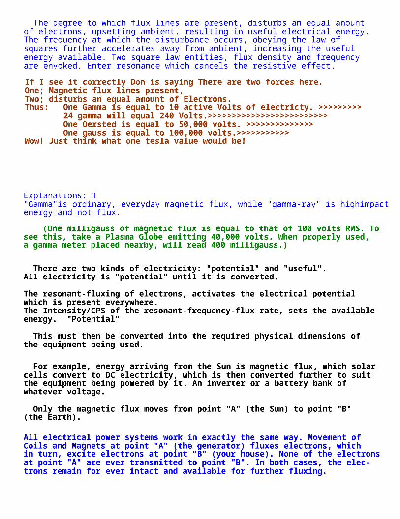
Explanations: 1 "Gamma"is ordinary, everyday magnetic flux, while "gamma-ray" is highimpact energy and not flux.
Zane
Zane
Zane
There are two kinds of electricity: "potential" and "useful". All electricity is "potential" until it is converted. The resonant-fluxing of electrons, activates the electrical potential which is present everywhere. The Intensity/CPS of the resonant-frequency-flux rate, sets the available energy. "Potential" This must then be converted into the required physical dimensions of the equipment being used.
Zane
For example, energy arriving from the Sun is magnetic flux, which solar cells convert to DC electricity, which is then converted further to suit the equipment being powered by it. An inverter or a battery bank of whatever voltage. Only the magnetic flux moves from point "A" (the Sun) to point "B" (the Earth).
Zane
All electrical power systems work in exactly the same way. Movement of Coils and Magnets at point "A" (the generator) fluxes electrons, which in turn, excite electrons at point "B" (your house). None of the electrons at point "A" are ever transmitted to point "B". In both cases, the elec- trons remain for ever intact and available for further fluxing.
Zane
(One milligauss of magnetic flux is equal to that of 100 volts RMS. To see this, take a Plasma Globe emitting 40,000 volts. When properly used, a gamma meter placed nearby, will read 400 milligauss.)
Zane
The degree to which flux lines are present, disturbs an equal anount of electrons, upsetting ambient, resulting in useful electrical energy. The frequency at which the disturbance occurs, obeying the law of squares further accelerates away from ambient, increasing the useful energy available. Two square law entities, flux density and frequency are envoked. Enter resonance which cancels the resistive effect.
Zane
If I see it correctly Don is saying There are two forces here. One; Magnetic flux lines present, Two; disturbs an equal amount of Electrons. Thus: One Gamma is equal to 10 active Volts of electricty. >>>>>>>>> 24 gamma will equal 240 Volts.>>>>>>>>>>>>>>>>>>>>>>>>> One Oersted is equal to 50,000 volts. >>>>>>>>>>>>>> One gauss is equal to 100,000 volts.>>>>>>>>>>> Wow! Just think what one tesla value would be!
Zane
Explanations: 2 Any coil system, when fluxed, causes electrons to spin and produce useful energy, once it is converted to the style required by its use. "A/C or D/C". Now that we have described the method which is required, let us now see how this concerns us. The entire System already exists and all that we need to do is to hook it up in a way which is useful to our required manner of use.
Zane
Only the magnetic flux passes through the input winding. No electrons pass through from the input side to the output side. Therefore, we only need to flux the output side of the transformer to have an electrical output.
Zane
A power correction factor system, being a capacitor bank, maintains an even flow of flux. These same capacitors, when used with a coil system (Your isolation transformer input side) become a frequency-timing system. Therefore, the inductance of the input side of the transformer, when combined with the capacitor bank, provides the required fluxing to produce the required electrical energy (cycles per second). That is, "inside", the output side of the Isolation transformer where the final induction process takes place.
Zane
Let us examine this backwards and start with a conventional output transformer. Consider one which has the required voltage and current handling characteristics and which acts as an isolation transformer.
Zane
Don is suggesting we start from the Isolation transformer, "output side". Moreover, if you are expecting to measure amperage in the input side of the isolation transformer, you do not yet understand Don's systems. Only at the output side of the isolation transformer does amperage become part of the equasion. All of the electrical manipulation before the induction side of the isolation transformer is high frequency wave, not dealing with impedance of the wires.
Zane
However, you are still only dealing with the density of magnetic flux you have aquired within your system. Your testing at this point should be with the appropriate test equipment!
Zane
Don Smith's "Earths Electrical System II"
Zane
E.E.S. II, BACKROUND INFORMATION and CONCEPT With alternating electrical current, electrons do not move from point "A" to point "B" as normally invisioned! Electrical potential (Oscill- ating electrons) at point "A" result in harmonic electron activity at point "B". When the grounding switch (circuit) is closed. That is to say, point "B" supplies it's own electrons and mirrors the activity at point "A". Impulsing (turbulence) by magnetic induction causes elec- trons to be pulled into the system, which then oscillates. When the magnetic field collapses (becomes absent) the electrical potential returnes to it's natural backround.
Zane
This Statement, "Being pulled into the system" And "the grounding switch" is as my interpritation like the Open door, a way to allow an additional energy to become part of the multiplied system's energy.
Zane
This study will limit it's scope to air core coil transformers at radio frequency and upward. The electrical power produced by this method is inverted to direct current and then to alternating current as required for popular usage.
Zane
These are Don's directions for some of the various devices within his E E S II group.
Zane
To start aquiring this extra energy we need two coils (Separate- apart), L-1 the reactor and L-2 the reactant coil. When L-1 is pulsed with say 1,200 volts A.C. through 10 turns, each turn will recieve 120 volts of potential. This induced magnetic field, then replicates itself in each turn of L-2 coil.
Zane
The Quality of Grounding is of Great value!
Zane
The quality of the grounding system determines the effictiveness of this method of producing electricty.
Zane
The last exerpt from this chapter is: In referance to the correct grounding dynamic. We are looking for the best negative groundings, "actually areas". I think as we set up each unit with one or multiple off the shelf grounding rods we should be in exelent shape.
Zane
Each time Hz's is doubled the effictiveness of induction is Squared.
Zane
At about 20,000 Hz when radio frequency is achieved the electrons begin spinning free outside the inductor. They become increasingly free of the inverse relationship of volt- amperes. From this point on, they replicate by the inductive process as V.A.R. (Volt-Ampers-Reactive). Volts and amperes are equal until resistnce is introduced. Therefore additional, not previously available electrons become incorporated for a very large net gain in potential.
Zane
Earth Electrical System II, Modular Units
Zane
The system consists of three seperate modules. Reverse engineering is used in matching the modules to the de- sired usage.
Zane
HIGH VOLTAGE INDUCTION TRANSFORMER MODUEL:
Zane
1. Preferably an off-the-shelf-unit similar to a TV flyback and/or ignition typerelated coil (Transformer) 2. Ratio of input to output may be fromless than 1/100 to greater than 1/1,000. A voltage tripler may be then used. 3. A connection allowing the high voltage output to pass onward through the induction coil L-1 and then to it's grounding.
Zane
AN AIR CORE INDUCTION COIL TRANSFORMER MODULE:
Zane
1. Two coils, the reactor coil L-1 and the reactant coil L-2 has a high voltage radio frequency capacitor between it and it's grounding. 2. Input into the L-1 inductor is devided by the number of turnes there- in. The magnetic flux field provided from each turn of L-1 rep- licates itself as an electrical potential in each turn of L-2. 3. L-2 may have one turn or many hundreds of turnes. The net gain depends upon the number of turnes of L-2. Output from L-2 is in V.A.R. (Volt-Ampers-Reactive).
Zane
With this type of output, volts and amperes are the same until work (resistivity) is introduced.
Zane
THE INVERTER MODULE:
Zane
1. Inverts to direct current (DC) 2. Inverts to alternating current (A.C.) as desired. 3. Provides customized output of electrical power ready for designed usage.
Zane
Do not use your ociliscope to measure these amplified magnetic, amp- erages and voltages, Serious damage can occur! To do this properly, mathmatecally figure out what the values should be, then measure with the appropriate tester, using extreme caution. Use a Guass meter to find the amount of gauss available.
Zane
These systems can be very simple, Looking at the next page, variations can be made and outputs made variable.
Zane
This being the Brief case device, "is said to be incomplete", lets consider what is here.
Zane
1. Battery 6 or 12 volt Dated 2. Diode Poss. a varactor Jan 17 1997 3. High Voltage module L-1 and L-2 4. Capacitor TDK 10.9 pF 30 KV 5. Spark plug Small engine .0025 in. gap 6. Inductor coil L-3 7. Induction coil L-4 8. Voltage controle shunt 9. Frequency adjuster prevents derating by diode bridge. 10. Diode bridge 200 nanosecond, rf > 100 KV 11. Voltage devider circuit, corrects voltage for next stage. 12. Capacitor Electrolytic, smoothes out DC and ripple effect 13. Earth Ground 14. Voltage devider circuit, connects voltage to transformer 15. Inverter circuit DC + in 60 CPS to transformer 16. Output from transformer to load. 17. Center tap: This has been stated in the Metacafe video this is the ground wire to make the device run.
Zane
Hard to read between the #8 and #14 on the right--> Note, # 12; is a capacitor bank and you need to expiriment to find the correct number, it will be a function of coloumbs (Volt - Amperes) required Note Above # 3; If the + connector # 7 wire is a wave length, of the # 6 or # 7s frequency, the battery will recharge itself while it is being used. To see this use two light emmiting diods. They show the direction the electrons are moving, DC electrons out and radio frequency electrons into the battery.
Don Smith's Suggestions: Get a copy of the "Handbook of Electronic Tables and Formulas", published by Sams, ISBN 0-672-22469-0, also an LCR meter is required. Chapter 1 in this book has important time constant (frequency) information and a set of reactance charts in nomograph style ("nomograph": a graph, usually containing three parallel scales graduated for different variables so that when a straight line connects values of any two, the related value may be read directly from the third at the point intersected by the line) which makes working, and approximating of the three variables (capacitance, inductance and resistance) much easier. If two of the variables are known, then the third one can be read from the nomograph. For example, if the input side of the isolation transformer needs to operate at 60 Hz, that is 60 positive cycles and 60 negative cycles, being a total of 120 cycles. Read off the inductance in Henries using the LCR meter attached to the input side of the isolation transformer. Plot this value on the (nomographic) reactance chart. Plot the needed 120 Hz on the chart and connect these two points with a straight line. Where this line crosses the Farads line and the Ohms line, gives us two values. Choose one (resistor) and insert it between the two leads of the transformer input winding. The Power Correction Factor Capacitor (or bank of more than one capacitor) now need adjusting. The following formula is helpful in finding this missing information. The capacitance is known, as is the desired potential to pulse the output transformer. One Farad of capacitance is one volt for one second (one Coulomb). Therefore, if we want to keep the bucket full with a certain amount, how many dippers full are needed? If the bucket needs 120 volts, then how many coulombs are required?
Now, go to the Reactance Chart mentioned above, and find the required resistor jumper to place between the poles of the Correction Factor Capacitor. A earth grounding is desirable as a voltage-limiter and transient spike control. Two are necessary, one at the Power Factor Capacitor and one at the input side of the isolation transformer. Off-the-shelf surge arrestors / spark gaps and varistors having the desired voltage/potential and amperage control are commonly available. Siemens, Citel America and others, make a full range of surge arrestors, etc. Varistors look like coin-sized flat capacitors. Any of these voltage limiters are marked as "V - 1" in the following text.
3 - 32
Zane
I should interject here, to bring it to the forefrount of your mind however counterintuitive it may seem, groundings to the Earth at various points within the systems are unusually odd. This is a closed part of the system yet is open to the Ambient. Look at the center tap below; I believe this is a ground in certain devices. Further, as you read you will notice Don says a ground at the bace of L-2 is an advantage.
Zane
Note; as referanced, The block wall is the base of a dipole, (or L-2 coil) this is the area of electron spin separation.
Zane
Selectively as you read through Don's report, you will notice in scem- atics, numerous Earth groundings are used in odd various places. This is probably the most important aspect of this entire literature!
Zane
As we are manipulating these electrical/magnetic impulses in an un- ordinary way, we should expect absolute modifications in our testing methods. Before the circuit breaker panel we can not expect normal current measurements. Moreover, stopping anywhere before this point and expecting to get the normal household currents and or voltages is absurd.
Zane
In the resonant induction system a very high percentage of the energy present is useful. When resonant, (Ohms-Impedance-Z)becomes zero and all energy present is available, undegraded. Ohms is load or wasted energy and ampers is the rate of wasting. Using this information, now apply it to an air-core coil, resonant transformer energy system. L-1 and L-2 coils are now present. L-1 has less turns and is many times the diameter of L-2. Input from a 12 V gelcel source produces 8,000 V with low (wasted energy) amperage into 4 turns of coil L-1. Each turn of L-1 recieves 2,000 V of resonant potential. Each turn of L-2 is then exposed the electric flux of 2,000 V. Each turn at the bottom end of L-2 aquire 2,000 V. The flux lines are squared and are additive to as the voltage and amperage progresses toward the top end of L-2's many turns.
Zane
Energy stored, times cycles per second, represents that being pumped by the system. Capacitors and inductors temporarly store electrons.
Zane
Capacitor formula; W = .5 X CE X C.P.S. W = energy in joules (watt seconds) c = capacitance in farads E = applied potential in volts squared Inductor (Coil ) formula; W = energy in joules (watt seconds) L = inductance in henrys I = current in amperes squared Both one henry and one farad = 1 Volt. The higher the cycles per second including the squaring flux lines cause a large increase in the amount of energy being produced.
Zane
The above combined with a resonant energy induction system, (all electrons moving at the same time, in the same direction), make the next move into overunity practical.
Zane
A huge amount of flux lines that were not previously present occure at the top end of L-2. These flux lines excite the electrons nearby in it's earth, and air groundings. This high level of excitment above the ambient causes a large amount of electrons not previously part of the energy present, to become available.
Zane
At this point overunity is present in large amounts!
Zane
Remember that amperage is wasted energy and untill that happens there is no amperage. This energy is turned into DC and then into the desired working frequency.
Zane
Zane
Variations of systems
Zane
What I see happening here is a simmalee like; "compressed gasseous material". Don is magnifying and collecting these Magnetic flux lines then we reduce the operating frequency or run it through a diode bridge or rectifier, whatever it takes. Thus it becomes consolidated or com- pressed. Then through the output transformer, varastor and breaker box.
Zane
Electrical Power Generation / Points of Referance
Zane
The electrical energy generation system here presented, the resonate Electrons all moving in the same direction at the same time. This allows NEAR UNITY ELECTRICAL POWER to devolop. This is the room temperature equivalent of super conductivity. The Energy System here presented consists of a properly adjusted and functional resonate air core coil tank. The electrical energy is stored in a tank and the magnetic energy in the coil system. From Maxwell and others, we know that electrical related energy has an equal amount of magnetic energy associated with it... "The formula which establishes the USEFUL ENERGY OF THE SYSTEM" Joules = [.5 C x V's squared] x C.P.S. squared Joules [Volts x Amperes x Seconds] = watt seconds C = Capacitance in microfarads V = Potential in Volts C.P.S. = Cycles Per Second In the RESONANTE TANK INDUCTION ENERGY TRANSFER SYSTEM here presented impedance [system resistance] replaces the conventionsl ohms usage. At Resonance impedance becomes Zero and the full force and effect of the Energy Transfer occures. This again is superconductor conditions room temperature. At radio frequencies the electrons do not pass through the conductor as at lower frequencies. These Electrons encircle the conductor and are free of the conductors resistance.
Zane
Useful electrical power is generated when electrons form Earth and Air groundings are disturbed by the movement of coils and magnets with referance to each other.
Zane
The resulting of electrical and magnetic energy is then changed to joules, (Watt seconds,Volts X Amps X Seconds). Each forward electron movement results in a magnetic impulse, and each return movement causes an elecrtical impulse. The composite of electrical energy impulses from these electrons yealds useful energy (Power).
Zane
Next Don reverts back to the Resonant system without the ambient included.
Zane
Example # 1 Let the ESTABLISHMENTS POWER GENERATION SYSTEM be "A" and the SYSTEM here presented be "B". "A" Given 60 CPS at 120 Volts and a 10 microfarad capacitor. Joules = [0.5 x .000,010 x 120 squared] x C.P.S's squared [ 120 X's 120 = 14,400 ] [ .000,010 X 14,400 = .144 ] [ .144 x .05 = .072 ] [.072 X 3,600 = 259.2 ] "B" Given One Million Cycles Per Second at 100,000 volts using a 10 microfarad capaitor. Joules = [ .05 X .000,010 X 100,000 squared ] X C.P.S.'s squared. [ 100,000 X 100,000 = 10,000,000,000 ] [ 10,000,000,000 X .000,010 = 100,000 ] [ 100,000 X 0.5 = 50,000 ] [ 50,000 x 1,000,000 Squared = 50,000,000,000,000,000 ] The useful Energy Available is greater than 50 Mega K-Joules actually 50 Mega-Mega joules. [Watt seconds] Since the Resonant Electrons are nonimpacting, all the Energy is available for direct usage. BENIFITS OF THE INVENTOR'S SYSTEM ARE SUMMERIZED 1. Induction Energy transfer is enhansed by squaring the cycles per second by the System. 2. Induction Energy transfer is enhansed by squaring the input voltage and amperage 3. The increase in flux lines occuring from the above, disturbing more electrons, causes more electrical energy to become available. 4. Resonant Induction has all the electrons moving unimpeded, resulting in superconductor conditions at room temperature. 5. A smaller amount of energy is used to disturb a larger number of electrons. Electrons not originally part of the System then combine their energy, resulting in a net gain in available usable power. 6. The physical size of the System [Device] is small. The Device dis- cribed in "B" sits comfortable on the breakfast table. 7. A small energy source is used to start the device and remains fully charged at all times from the system.
1. Substitute a Plasma Globe such as Radio Shack's "Illumna-Storm" for the source-resonant induction system. It will have about 400 milligauss of magnetic induction. One milligauss is equal to 100 volts worth of magnetic induction.
2. Construct a coil using a 5-inch to 7-inch (125 to 180 mm) diameter piece of PVC for the coil former. 3. Get about 30 feet (10 m) of Jumbo-Speaker Cable and separate the two strands. This can be done by
sticking a carpet knife into a piece of cardboard or wood, and then pulling the cable carefully past the blade to separate the two insulated cores from each other. (PJK Note: "Jumbo-Speaker Cable" is a vague term as that cable comes in many varieties, with anything from a few, to over 500 strands in each core. As Don points out that the output power increases with each turn of wire, it is distinctly possible that each of these strands acts the same as individual insulated turns which have been connected in parallel, so a 500-strand cable may well be far more effective than a cable with just a few strands).
4. Wind the coil with 10 to 15 turns of wire and leave about 3 feet (1 m) of cable spare at each end of the
coil. Use a glue gun to hold the start and finish of the coil. 5. This will become the "L - 2" coil shown in the Circuits page. 6. When sitting on top of the Plasma Globe (like a crown) you have a first-class resonant air-core coil
system. 7. Now, substitute two or more capacitors (rated at 5,000 volts or more) for the capacitor bank shown on the
Circuits page. I use more than two 34 microfarad capacitors. 8. Finish out the circuit as shown. You are now in business ! 9. Voltage - Amperage limiting resistors are required across the output side of the Load transformer. These
are used to adjust the output level and the desired cycles per second.
3 - 31
Zane
Directions: Plasma Globe, first-class resonant air-core coil system
Zane
1. Substitute a Plasma Globe such as Radio Shack's "Illumna Storm" for the source-resonant induction system. It will have about 400 milligauss of magnetic induction. One milligauss is equal to 100 volts worth of magnetic induction. 2. Construct a coil using a 5-inch to 7-inch diameter piece of PVC for the coil former. 3. Get about 30 feet (10 m) of Jumbo-Speaker Cable and separate the two strands. As Don points out that the output power increases with each turn of wire, it is distinctly possible that each of these strands acts the same as individual insulated turns which have been connected in parallel, so a 500-strand cable may well be far more effective than a cable with just a few strands).
Zane
4. Wind the coil with 10 to 15 turns of wire and leave about 3 feet (1 m) of cable spare at each end of the coil. Use a glue gun to hold the start and finish of the coil. 5. This will become the "L - 2" coil shown in the Circuits page. 6. When sitting on top of the Plasma Globe (like a crown)you have a first-class resonant air-core coil system.
Zane
7. Now, substitute two or more capacitors (rated at 5,000 volts or more) for the capacitor bank shown on the Circuits page. I use more than two 34 microfarad capacitors. 8. Finish out the circuit as shown. You are now in business! 9. Voltage - Amperage limiting resistors are required across the output side of the Load transformer. These are used to adjust the output level and the desired cycles per second.
Zane
Zane
Don Smith's Suggestions: Get a copy of the "Handbook of Electronic Tables and Formulas", pub- lished by Sams, ISBN 0-672-22469-0, also an LCR meter is required. Chapter 1 in this book has important time constant (frequency) inform- ation and a set of reactance charts in nomograph style which makes working, and approximating of the three variables (capacitance, in- ductance and resistance)much easier. If two of the variables are known, then the third one can be read from the nomograph.
Don Smith's Suggestions: Get a copy of the "Handbook of Electronic Tables and Formulas", published by Sams, ISBN 0-672-22469-0, also an LCR meter is required. Chapter 1 in this book has important time constant (frequency) information and a set of reactance charts in nomograph style ("nomograph": a graph, usually containing three parallel scales graduated for different variables so that when a straight line connects values of any two, the related value may be read directly from the third at the point intersected by the line) which makes working, and approximating of the three variables (capacitance, inductance and resistance) much easier. If two of the variables are known, then the third one can be read from the nomograph. For example, if the input side of the isolation transformer needs to operate at 60 Hz, that is 60 positive cycles and 60 negative cycles, being a total of 120 cycles. Read off the inductance in Henries using the LCR meter attached to the input side of the isolation transformer. Plot this value on the (nomographic) reactance chart. Plot the needed 120 Hz on the chart and connect these two points with a straight line. Where this line crosses the Farads line and the Ohms line, gives us two values. Choose one (resistor) and insert it between the two leads of the transformer input winding. The Power Correction Factor Capacitor (or bank of more than one capacitor) now need adjusting. The following formula is helpful in finding this missing information. The capacitance is known, as is the desired potential to pulse the output transformer. One Farad of capacitance is one volt for one second (one Coulomb). Therefore, if we want to keep the bucket full with a certain amount, how many dippers full are needed? If the bucket needs 120 volts, then how many coulombs are required?
Now, go to the Reactance Chart mentioned above, and find the required resistor jumper to place between the poles of the Correction Factor Capacitor. A earth grounding is desirable as a voltage-limiter and transient spike control. Two are necessary, one at the Power Factor Capacitor and one at the input side of the isolation transformer. Off-the-shelf surge arrestors / spark gaps and varistors having the desired voltage/potential and amperage control are commonly available. Siemens, Citel America and others, make a full range of surge arrestors, etc. Varistors look like coin-sized flat capacitors. Any of these voltage limiters are marked as "V - 1" in the following text.
3 - 32
Zane
Step # 1 For example, if the input side of the isolation transformer needs to operate at 60 Hz, that is 60 positive cycles and 60 negative cycles, being a total of 120 cycles. Read off the inductance in Henries using the LCR meter attached to the input side of the isolation transformer. Plot this value on the (nomographic) reactance chart. Plot the needed 120 Hz on the chart and connect these two points with a straight line. Where this line crosses the Farads line and the Ohms line, gives us two values. Choose one (resistor) and insert it between the two leads of the transformer input winding.
Zane
Desired Voltage ____________________________ Capacitence in Microfarads
Zane
= Required Frequency in Hertz
Zane
Now, go to the Reactance Chart mentioned above, and find the required resistor jumper to place between the poles of the Correction Factor Cap- acitor.
Zane
The capacitance is known, as is the desired potential to pulse the out- put transformer. One Farad of capacitance is one volt for one second (one Coulomb). Therefore, if we want to keep the bucket full with a certain amount, how many dippers full are needed? If the bucket needs 120 volts, then how many coulombs are required?
Zane
Step # 2 The Power Correction Factor Capacitor (or bank of more than one capaci- tor) now need adjusting. The following formula is helpful in finding this missing information.
Zane
None of the electrons active at the power source (battery) are passed through the system for use downstream. At any point, if the magnetic flux rate should happen to vary, then the number of active electrons also varies. Therefore, controlling the flux rate controls the electron (potential) activity. Electrons active at point "A" are not the same electrons active at point "B", or point "C", and so on. If the magnetic flux rate (frequency Hz) varies, then a different number of electrons will be disturbed. This does not violate any Natural Law and does pro- duce more energy out than in, "should that be desirable".
Zane
Example # 1 It should be obvious that several separate closed circuits are present in the suggested configuration: The power input source, The high-voltage module, A power factor capacitor bank, combined with the input side of the isolation transformer. Lastly, the output side of the isolation transformer and its load.
Zane
A convenient high-voltage module is a 12 volt DC neon tube transformer. The Power Factor Correction Capacitors should be as many microfarads as possible as this allows a lower operating frequency. The 12-volt neon tube transformer oscillates at about 30,000 Hz. At the Power Correction Factor Capacitor bank we lower the frequency to match the input side of the isolation transformer. Other convenient high-voltage sources are car ignition coils, television flyback transformers, laser printer modules, and various other devices. Always lower the frequency at the Power Factor Correction Capacitor and correct, if needed, at the input side of the isolation transformer.
Zane
The isolation transformer comes alive when pulsed. "Amperage becomes a part of the consideration only at the isolation transformer".
Zane
Transformer designs resulting in hysteresis, "magnetic saturation", creates heat, which selfdestructs the transformer if it is overloaded. Transformers which have a composite core run cool and can tolerate much higher amperage.
Zane
Step # 3 An earth grounding is desirable as a voltage-limiter and transient spike control. Two are necessary, one at the Power Factor Capacitor and one at the input side of the isolation transformer.
Zane
Off-the-shelf surge arrestors / spark gaps and varistors having the desired voltage/potential and amperage control are commonly available. Siemens, Citel America and others, make a full range of surge arrestors, etc. Varistors look like coin-sized flat capacitors. Any of these voltage limiters are marked as "V - 1" in the following text.
Zane
As per Mr. Smith detail instructions: A Plasma Globe; I chose to get the Precise "Illuma Storm" from an E-bay sale... I feel I need to understand what was being produced by this plasma globe so I would precisely have a correct understanding of what are the values, how these values are created and what Don says they do! First, The plasma globe supposidly produces a magnetic field. Now my plasma globe has two slider pots one is labled Intensity, the other is labeled Focus. The intencity one acts like a volume controle and the Focus one acts like a boat throttle controle F/R lever. So I am going to presume the focus is able to deliver something like + magnetic, and - magnetic signals. Example; When I moderate them to a least amount of this determination "the focus is nearly in the middle and the intencity is nearly all the way left", I get about 10 inconsistant magnetic threads touching the sphere. These threads concentrate themselves toward the top hemisphirical area of the protruding electrode, they do not migrate down to the lower parts of the globe. I do not have a Gauss meter yet so I am not sure about this magnetic field being + or - in orientation.
Zane
My build, The plasma globe...
Zane
The L-2 Coil
Zane
Ref. # (6.) When sitting on top of the Plasma Globe (like a crown)you have a first-class resonant air-core coil system.
Zane
I bought 30' of this wire; "( http://www.knukonceptz.com/product Detail.cfm?prod ID=KLE10BL ), for $ 22.5. After I competed this order, I found another "power cable type" from this same supplier with more wires in the sheeth, but I will build the first with this type. I found a piece of PVC pipe 6 5/8 diameter, = 20.8131 circumference / 12" = 1.7344' per revolution * 15 turnes = 26.0163' of wire. 30' of wire will work nicely ! I need to cut the pipe cleanly so I will make a jig on my table saw or take it to my bosses shop and turn it on an old lathe there. I was bairly able to turn it on the old girl, the throw was only 5" but the deck was about 7" so the best I could do, worked. I made three pieces 3", 4" and 5". The 3" holdes just over 14 1/2 rounds of the jumbo speaker wire tightly. I used electric tape to secure the wire to the pipe.
Zane
The capacitor bank...
Zane
What we are looking for is more than two, with 5Kw 34uF capacitance, I do not know how many that is, so I figured I should get at least four. Looking at another device on u-tube Don displays Capacitors with large capacitance that are truely small. The picture at the beginning of this document shows four yellow components connected to the L-2 coil, these are probably the capacitors. What I need to understand is what configuration to allign these caps, series, paralell or yet another configurtion, "see next Page".
Zane
Series Voltage: C total = 1 / ((1 / C1) + (1 / C2) + (1 / C3) + (1 / etc.)) Voltage rating is the rating of the smallest capacitor times the number of capacitors. Parallel Voltage: C total = C1 + C2 + C3 + etc. Voltage rating is the rating of the smallest capacitor. Series Farads: Capacitors in series combined is slightly less than least capacitance of the smallest capacitor. Paralell Farads: Capacitors in paralell are added together, the sum is the value of capacitance.
Zane
My Isolation Transformer
Zane
The inductance turned out to be 112 mH The Reactance chart turned out to show 75 Ohm resistance at 120 Hz. This may change after I hook up the capacitors and the L-2 coil, I do not know. I understand I need a 75 Ohm resistor here but I am not sure if it needs to be rated at high voltage. Dugh
Zane
My my my, I found a transformer on e-bay rated at 30 to 50 amps @ 120 - 240 volts. This equates to on the high side 7,200 to 12,000 KV. A Monster, UPS box said 80# but it only weighs about 65# I guess.