Embed Size (px)
Citation preview

Intentional weld defect process: from manufacturing by
robotic welding machine to inspection using TFM phased
array
Yashar Javadi1, a), Momchil Vasilev1, b), Charles N. MacLeod1, c), Stephen G.
Pierce1, d), Riliang Su1, e), Carmelo Mineo1, f), Jerzy Dziewierz1, g) and Anthony
Gachagan1, h)
1 Centre for Ultrasonic Engineering (CUE), Department of Electronic & Electrical Engineering, University of
Strathclyde, Glasgow G1 1XQ, UK.
a)Corresponding author: [email protected]
b)[email protected] c)[email protected]
d)[email protected] e)[email protected]
f)[email protected] g)[email protected]
Abstract. Specimens with intentionally embedded weld defects or flaws can be employed for training, development and
research into procedures for mechanical property evaluation and structural integrity assessment. It is critical that the
artificial defects are a realistic representation of the flaws produced by welding. Cylindrical holes, which are usually
machined after welding, are not realistic enough for our purposes as it is known that they are easier to detect than the
naturally occurring imperfections and cracks. Furthermore, it is usually impractical to machine a defect in a location similar
to where the real weld defects are found. For example, electro-discharge machining can produce a through hole (cylindrical
reflector) which neither represents the weld porosity (spherical voids) nor the weld crack (planar thin voids). In this study,
the aim is to embed reflectors inside the weld intentionally, and then locate them using ultrasonic phased array imaging.
The specimen is an 8 mm thick 080A15 Bright Drawn Steel plate of length 300 mm. Tungsten rods (ø2.4-3.2 mm & length
20-25 mm) and tungsten carbide balls (ø4 mm) will be used to serve as reflectors simulating defects within the weld itself.
This study is aligned to a larger research project investigating multi-layer metal NDE found in many multi-pass welding
and wire arc additive manufacturing (WAAM) applications and as such, there is no joint preparation as the first layer is
deposited over the plate surface directly and subsequent layers contribute to the specimen build profile, similar to the
WAAM samples. A tungsten inert gas welding torch mounted on a KUKA robot is used to deposit four layers for each
weld, with our process using nine passes for the first layer, down to six passes for the last layer. During this procedure, the
tungsten artificial reflectors are embedded in the weld, between the existing layers. The sample is then inspected by a 10
MHz ultrasonic phased array in direct contact with the sample surface using both conventional and total focusing method
(TFM) imaging techniques. A phased array aperture of 32 elements has been used. The phased array controller is FIToolbox
(Diagnostic Sonar, UK). Firstly, a focused B-scan has been performed with a range of settings for the transmit focal depth.
Secondly, a full-aperture TFM method has been processed. All the reflectors of interest were detected successfully using
this combination of B-scan and TFM imaging approaches.
brought to you by COREView metadata, citation and similar papers at core.ac.uk
provided by Archivio istituzionale della ricerca - Università di Palermo
INTRODUCTION
Intentional weld defects or flaws can be used for non-destructive testing (NDT) operator training, development
and research into procedures for mechanical property evaluation and structural integrity assessment. It is critical to
producing the artificial defects as realistic as possible to represent thewelding defects1. Crutzen et al2 concluded that
the use of side-drilled holes, SDH, or flat-bottomed-holes, FBH, to validate the NDT techniques could result in an
optimistic evaluation of the technological capabilities, jeopardizing the inspection of structures containing real defects,
particularly those employed in the high-risk applications (e.g., nuclear and aerospace industry). Consonni et al3 showed
a procedure to produce the realistic defects representative of the morphology of the most common defect types in the
welded structures (e.g., lack of fusion, slag inclusion, solidification cracking, etc.).
The inspection method used in this study is the ultrasonic phased array. As the high-technology electronics are
increasingly available to the market at a lower cost, the phased array systems are attracting more attention4. The
ultrasonic phased array uses a linear array of transducers rather than a single element probe. This approach is based
on using parallel transmission circuits which are independently controlled. In comparison with the single element
transducers, ultrasonic arrays can provide a scanning area with an index of the width of the probe, a higher inspection
quality with flexibility and fewer inspection time5-7.
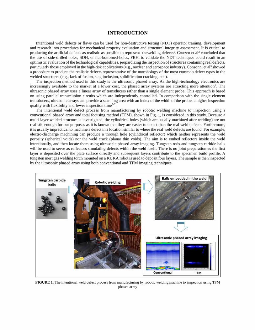
The intentional weld defect process from manufacturing by robotic welding machine to inspection using a
conventional phased array and total focusing method (TFM), shown in Fig. 1, is considered in this study. Because a
multi-layer welded structure is investigated, the cylindrical holes (which are usually machined after welding) are not
realistic enough for our purposes as it is known that they are easier to detect than the real weld defects. Furthermore,
it is usually impractical to machine a defect in a location similar to where the real weld defects are found. For example,
electro-discharge machining can produce a through hole (cylindrical reflector) which neither represents the weld
porosity (spherical voids) nor the weld crack (planar thin voids). The aim is to embed reflectors inside the weld
intentionally, and then locate them using ultrasonic phased array imaging. Tungsten rods and tungsten carbide balls
will be used to serve as reflectors simulating defects within the weld itself. There is no joint preparation as the first
layer is deposited over the plate surface directly and subsequent layers contribute to the specimen build profile. A
tungsten inert gas welding torch mounted on a KUKA robot is used to deposit four layers. The sample is then inspected
by the ultrasonic phased array using both conventional and TFM imaging techniques.
FIGURE 1. The intentional weld defect process from manufacturing by robotic welding machine to inspection using TFM
phased array

THEORETICAL BACKGROUND
The ultrasonic array allows real-time images (B-scans) to be generated in three standard inspection techniques:
plane B-scan; focused B-scan and sector B-scan7. In the plane swept B-scan, a number of adjacent elements, aperture,
are pulsed at the same time to produce a planar beam. This can overcome the beam divergence and low sensitivity due
to a poor lateral resolution which is expected to be produced when a small size single element is fired7. The time
domain signals received from the aperture are then summed to produce a single signal and the performance is same
as a plane transducer of the same size as the aperture. To produce the final B-scan image, the aperture is electronically
moved along the array length7. In the focused B-scan, the elements within an aperture are used to introduce time
delays, at both the transmission and reception stages, in order to produce a focused beam7. Commercial dynamic depth
focusing array systems can enable focusing at different depths below the aperture by multiple firings with different
delay sequences in the transmission, which is limited by the overall frame rate, and also with the number of delay
sequences in the reception, which is limited by the computational power7. A sector B-scan uses all elements to steer
the beam through an angular sweep to generate one scan line in the final image through each incremental steering
angle. Each scan line then requires a unique element pulse sequence due to the unique steering angle of each line with
respect to the transducer face7.
The above three B-scan approaches utilize a set of time-domain data (A-scans). If all combinations of transmitting
and receiving elements are captured, a full matrix capture (FMC) is achieved. This can maximize the flexibility of
array signal processing and extract as much information as possible from an array6-8. Total focusing method (TFM) is
an imaging algorithm that uses data acquired in FMC mode for post-processing and then all elements in the array are
employed to focus at every single point in the image7.
Multi-element synthetic aperture (multi-aperture) technique employs sub-aperture processing over successive
firing steps. The multi-aperture method is popular because it can increase the signal-to-noise ratio (SNR) achieving
higher image quality9, 10.
MANUFACTURING SETUP
This work is aligned to a larger research project investigating multi-layer metal NDE found in many multi-pass
welding and wire arc additive manufacturing (WAAM) applications. In the WAAM method, there is no weld joint
preparation and instead, the wire is part-melted and deposited onto the virgin material. Similarly, the first layer of the
investigated sample in this study is deposited over the plate surface directly and three more subsequent layers
contribute to the specimen build profile. The plate is an 8 mm thick 080A15 Bright Drawn Steel of length 300 mm. A
tungsten inert gas welding torch mounted on a KUKA robot, see Fig. 2, is used to deposit four layers for each weld,
with our process using 9 passes for the first layer, down to 6 passes for the last layer.
FIGURE 2. Robotic welding setup
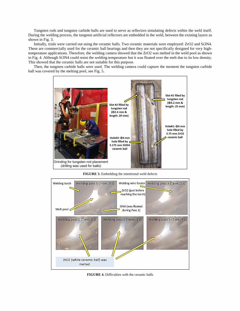
Tungsten rods and tungsten carbide balls are used to serve as reflectors simulating defects within the weld itself.
During the welding process, the tungsten artificial reflectors are embedded in the weld, between the existing layers as
shown in Fig. 3.
Initially, trials were carried out using the ceramic balls. Two ceramic materials were employed: ZrO2 and Si3N4.
These are commercially used for the ceramic ball bearings and then they are not specifically designed for very high-
temperature applications. Therefore, the welding camera showed that the ZrO2 was melted in the weld pool as shown
in Fig. 4. Although Si3N4 could resist the welding temperature but it was floated over the melt due to its low density.
This showed that the ceramic balls are not suitable for this purpose.
Then, the tungsten carbide balls were used. The welding camera could capture the moment the tungsten carbide
ball was covered by the melting pool, see Fig. 5.
FIGURE 3. Embedding the intentional weld defects
FIGURE 4. Difficulties with the ceramic balls

FIGURE 5. Tungsten carbide ball being covered by the melting pool
Eventually, the following defects and imperfections were successfully embedded inside the sample (see Fig. 6):
L1: 1st layer (9 welding passes).
L2&3: 2nd and 3rd layers (8 welding passes).
L4: 4th layer (6 welding passes).
S1: Tungsten rod (ø3.2 mm – length: 25 mm).
S2: Tungsten rod (ø2.4 mm – length: 20 mm).
H2: A tungsten carbide ball (ø4 mm) inside a drilled hole (ø4 mm – depth: 5 mm).
H3: A vertical tungsten rod (ø2.4 mm – length: 2 mm) inside a drilled hole (ø4 mm – depth: 6 mm).
H4: A tungsten carbide ball (ø4 mm) inside a drilled hole (ø4 mm – depth: 3 mm).
FIGURE 6. Defects successfully embedded inside the sample
PHASED ARRAY INSPECTION SETUP
Due to the process applied, the weld top surface is not flat. Hence, the inspection was carried out on the other side
of the specimen (bottom surface of the base plate as shown in Fig. 7). The sample is inspected by 5 MHz and 10 MHz
ultrasonic phased array (128 elements without the wedge, contact method). The phased array controller is Diagnostic
Sonar FIToolbox. Firstly, a focused B-scan has been performed with a range of settings for the transmit focal depth.
A phased array aperture of 32 elements has been used to allow exciting/receiving 32 elements simultaneously (multi-
aperture method; Tx&Rx: 32). Secondly, TFM method has been used.

FIGURE 7. Phased array scanning of the bottom surface
RESULTS AND DISCUSSIONS
The inspection results using the conventional phased array method by 5 MHz array are shown in Fig. 8. S1 had
been placed in a position deeper than S2 and then in the inspection from the other side, S2 was shown in more distance
from the scanning surface. There was an obvious welding deformation on the sample which made the phased array
inspection more difficult especially for S2.
FIGURE 8. Conventional phased array (5 MHz)
The focused B-Scan, shown in Fig. 9, produced clearer images in comparison with the conventional phased array.
Application of multi-aperture (Tx&Rx: 32 means an aperture of 32 for both transmitter and receiver) along with the
focused B-Scan resolved the depth issue we had with the conventional phased array scanning of H2 and H4.
Furthermore, application of TFM, see Fig. 10 and 11, was helpful to validate the conventional phased array results
and higher quality images are achieved.

FIGURE 9. Focused B-scan (10 MHz)
FIGURE 10. TFM (5 MHz) to detect S1 and S2

FIGURE 11. TFM (5 MHz) to detect H2 and H3
CONCLUSIONS
The intentional weld defect process was considered in this study. In the manufacturing step, the ceramic and
tungsten carbide balls along with tungsten rods were embedded in a multi-layer weld deposited by a tungsten inert gas
welding torch mounted on a KUKA robot. The inspection process included conventional phased array, focused B-
scan and TFM imaging techniques. Based on the achieved results, it can be concluded that:
Application of the ceramic balls was not practical and then tungsten carbide balls and tungsten rods were
successfully used for the intentional weld defects.
The welding deformation can increase difficulties of the phased array ultrasonic inspection.
All the reflectors of interest were detected successfully using a combination of focused B-scan and TFM
imaging approaches.
REFERENCES
1. M. Kemppainen, I. Virkkunen, J. Pitkanen, R. Paussu and H. Hanninen, Nuclear Engineering and Design
224 (1), 105-117 (2003).
2. S. Crutzen, P. Lemaitre and I. Iacono., presented at the 14th International Conference on NDE in the Nuclear
and Pressure Vessel Industries, Stockholm, Sweden, 1996 (unpublished).
3. M. Consonni, C. F. Wee and C. Schneider, Insight 54 (2), 76-+ (2012).
4. P. Cawley, Proc. Inst. Mech. Eng. Pt. L-J. Mater.-Design Appl. 215 (L4), 213-223 (2001).
5. B. W. Drinkwater and P. D. Wilcox, Ndt & E International 39 (7), 525-541 (2006).
6. C. Holmes, B. W. Drinkwater and P. D. Wilcox, Ultrasonics 48 (6-7), 636-642 (2008).
7. C. Holmes, B. W. Drinkwater and P. D. Wilcox, Ndt & E International 38 (8), 701-711 (2005).
8. S. Chatillon, G. Cattiaux, M. Serre and O. Roy, Ultrasonics 38 (1-8), 131-134 (2000).
9. M. Karaman, H. S. Bilge and M. O'Donnell, Ieee Transactions on Ultrasonics Ferroelectrics and Frequency
Control 45 (4), 1077-1087 (1998).
10. J. A. Johnson, M. Karaman and B. T. Khuri-Yakub, Ieee Transactions on Ultrasonics Ferroelectrics and
Frequency Control 52 (1), 37-50 (2005).