Embed Size (px)
Citation preview

Machine Vision and ApplicationsDOI 10.1007/s00138-007-0085-z
ORIGINAL PAPER
Intelligent perception and control for space roboticsAutonomous Satellite Rendezvous and Docking
Faisal Qureshi · Demetri Terzopoulos
Received: 24 July 2006 / Accepted: 23 February 2007© Springer-Verlag 2007
Abstract We present a space robotic system capable ofcapturing a free-flying satellite for the purposes of on-orbitsatellite servicing. Currently such operations are carried outeither manually or through discrete-event scripted control-lers. The manual approach is costly and exposes astronautsto danger, while the scripted approach is tedious and brit-tle. Consequently, there is substantial interest in performingthese operations autonomously, and the work presented hereis a step in this direction. To our knowledge, ours is the onlysatellite-capturing system that relies on vision and cognitionto deal with an uncooperative satellite. Our innovative sys-tem combines visual perception (object identification, recog-nition, and tracking) with high-level reasoning in a hybriddeliberative/reactive computational framework. The reaso-ning module, which encodes a model of the environment,performs deliberation to control the perception pipeline—it guides the vision system, validates its performance, andsuggests corrections when vision is performing poorly. Fur-thermore, it advises the behavioral controller to carry out itstasks. Reasoning and related elements, among them inten-tion, context, and memory, are responsible for the robustnessand reliability of the overall system. We demonstrate our pro-totype system controlling a robotic arm that autonomouslycaptures a free-flying satellite in a realistic laboratory settingthat faithfully mimics on-orbit conditions.
F. Qureshi (B)Department of Computer Science, University of Toronto,10 Kings College Road, Room 3304,Toronto, ON M5S-3G4, Canadae-mail: [email protected]
D. TerzopoulosComputer Science Department, University of California,Los Angeles, 4732 Boelter Hall, Los Angeles,CA 90095-1596, USAe-mail: [email protected]
1 Introduction
Since the earliest days of the computer vision field, resear-chers have struggled with the challenge of effectively combi-ning low-level vision with artificial intelligence (AI). Someof the earliest work involved the combination of image ana-lysis and symbolic AI to construct robots capable of autono-mous, task-driven operation [31,36]. These early attemptsmet with limited success, in part because the vision pro-blem is hard [43]. The focus of vision research then shif-ted from vertically-integrated vision systems to low-levelvision modules. Currently available low- and intermediate-level vision algorithms are sufficiently competent to supportsubsequent levels of processing. Consequently, there now isrenewed interest in high-level vision, which is necessary ifwe are to realize autonomous robots capable of performinguseful talks in dynamic, unpredictable environments.
In this paper, we report on research in the domain of spacerobotics. In particular, we design a visually guided roboticsystem capable of autonomously performing the challengingtask of capturing a non-cooperative, free-flying satellite forthe purposes of on-orbit satellite servicing. Our innovativesystem features object recognition and tracking combinedwith high-level symbolic reasoning within a hybrid delibera-tive/reactive computational framework, called the CognitiveController (CoCo).
The work reported herein was done in collaboration withMD Robotics, Ltd.(currently MDA Space Missions), a Cana-dian company that has supported human space flight sincethe early 1980s through advanced robotic systems, such asthe Space Shuttle’s Canadarm and the Mobile Servicing Sys-tem for the International Space Station. The company, whichundertakes extensive R&D projects in-house and throughcollaborations with universities and research institutions,regards autonomy as a necessary capability for future space
123

F. Qureshi, D. Terzopoulos
robotics missions. The reported work was done as part of theROSA (Remote Operation with Supervised Autonomy) pro-ject [17], which arose from this long-term vision. ROSA’sgoal is to advance the state of the art (operator commandsand discrete-event scripted control) by making possible aremote system that can perform decisions in real time within adynamic environment using high-level artificial intelligencetechniques combined with robotic behavioral control andmachine vision.
1.1 On-orbit satellite servicing
On-orbit satellite servicing is the task of maintaining andrepairing a satellite in orbit. It extends the operational life ofthe satellite, mitigates technical risks, reduces on-orbit losses,and helps manage orbital debris. Hence, it is of interest tomultiple stakeholders, including satellite operators, manu-facturers, and insurance companies [13,28]. Although repla-cing a satellite is more cost-effective in some cases, on-orbitservicing is critical for more expensive satellite systems, suchas space-based laser and global positioning system constella-tions, or for one-of-a-kind systems like the Hubble telescope,which costs $2.5 billion. As early as the 1980s, the NationalAeronautics and Space Administration realized the impor-tance of on-orbit servicing for protecting their assets in space[28].
Currently, on-orbit satellite servicing operations are car-ried out manually; i.e., by an astronaut. However, mannedmissions are usually very costly and there are human safetyconcerns.1 Furthermore, it is currently impracticable to carryout manned on-orbit servicing missions for satellites in geo-synchronous equatorial orbit (GEO), as the space shuttle cannot reach them. Unmanned, tele-operated, ground-controlledmissions are infeasible due to communications delays, inter-mittence, and limited bandwidth between the ground and theservicer. A viable alternative is to develop the capability ofautonomous on-orbit satellite servicing.
1.2 Autonomous satellite rendezvous and docking
A critical first phase of any on-orbit satellite servicing mis-sion, be it for the purpose of refueling, reorbiting, repai-ring, etc., involves rendezvousing and docking with the satel-lite. From the perspective of the software responsible forcontrolling the sensory apparatus and robotic manipulator,the rendezvousing step is the most interesting and challen-ging. Once the satellite is secured, we can assume a staticworkspace and handle the remaining steps using more pri-mitive scripted controllers [17]. Most national and internatio-
1 The Hubble telescope captured the imagination of the public during itshighly publicized repair missions, which were carried out by astronauts.By some estimates, these repairs cost taxpayers as much as $12 billion.
nal space agencies realize the important role of autonomousrendezvous and docking (AR&D) operations in future spacemissions and now have technology programs to develop thiscapability [19,45].
Autonomy entails that the on-board controller be capableof estimating and tracking the pose (position and orienta-tion) of the target satellite and guiding the robotic manipu-lator as it (1) approaches the satellite, (2) maneuvers itselfto get into docking position, and (3) docks with the satellite.The controller should also be able to handle anomalous situa-tions, which might arise during an AR&D operation, withoutjeopardizing its own safety or that of the satellite. Anotherrequirement that is desirable for space operations is that ofsliding autonomy, where a human operator can take over themanual operation of the robotic system at any level of thetask hierarchy [10,40]. Sliding autonomy enhances the relia-bility of a complex operation and it expands the range andcomplexity of the tasks that a robotic system can undertake.
1.3 Contributions
In this paper, we develop a visually-guided AR&D systemand validate it in a realistic laboratory environment that emu-lates on-orbit lighting conditions and target satellite drift. Toour knowledge, ours is the only AR&D system that usesvision as its primary sensory modality and can deal with anuncooperative target satellite. Other AR&D systems eitherdeal with target satellites that communicate with the servi-cer craft about their heading and pose, or use other sensingaids, such as radar and geostationary position satellite sys-tems [33].
Our system features CoCo, a new hybrid robot control fra-mework that combines a behavior-based reactive componentand a logic-based deliberative component. CoCo draws uponprior work in AI planning, plan-execution, mobile robotics,ethology, and artificial life. Its motivation comes from thefact that humans, who are sophisticated autonomous agents,are able to function in complex environments through a com-bination of reactive behavior and deliberative reasoning. Wedemonstrate that CoCo is useful in advanced robotic systemsthat require or can benefit from highly autonomous opera-tion in unknown, non-static surroundings, especially in spacerobotics where large distances and communication infra-structure limitations render human teleoperation exceedinglydifficult. In a series of realistic laboratory test scenarios, wesubject our CoCo AR&D system to anomalous operationalevents, forcing its deliberative component to modify existingplans in order to achieve mission goals. The AR&D control-ler demonstrates the capacity to function in important waysin the absence of a human operator.
Our AR&D prototype meets the operational requirementsby controlling the visual process and reasoning about theevents that occur in orbit. The system functions as follows:
123

Intelligent perception and control for space robotics
Fig. 1 Images acquired during satellite capture. The left and centerimages were captured using the shuttle bay cameras. The right imagewas captured by the end-effector camera. The center image shows thearm in hovering position prior to the final capture phase. The shuttle
crew use these images during satellite rendezvous and capture to locatethe satellite at a distance of approximately 100 m, to approach it, and tocapture it with the Canadarm—the shuttle’s manipulator
First, captured images are processed to estimate the cur-rent position and orientation of the satellite (Fig. 1). Second,behavior-based perception and memory units use contextualinformation to construct a symbolic description of the scene.Third, the cognitive module uses knowledge about scenedynamics encoded using the situation calculus to constructa scene interpretation. Finally, the cognitive module formu-lates a plan to achieve the current goal. The scene descriptionconstructed in the third step provides a mechanism to verifythe findings of the vision system. Its ability to plan enablesthe system to handle unforeseen situations.
The performance of the system results from the coopera-tion of its components, including low-level visual routines,short and long-term memory processing, symbolic reaso-ning, and the servo controllers of the robotic arm used tocapture the satellite. Competent, reliable low-level visualroutines are essential for meaningful higher-level proces-sing. Consequently, the AR&D system depends upon thereliable operation of the low-level object recognition, tra-cking, and pose-estimation routines. The AR&D system isable to handle transient errors in the low-level visual rou-tines, such as momentary loss of tracking, by using short-termmemory facilities. However, it cannot accomplish the taskwhen the low-level vision algorithms altogether fail to trackthe satellite, in which case the high-level routines abort themission. Stable servoing routines that account for the mani-pulator’s dynamics are vital for a successful AR&D mission.Hence, the AR&D prototype developed here assumes thatthe robotic arm can servo competently under the guidance ofthe higher level modules. Although we have not proved thecorrectness of the reasoning module, it appears in practice tomeet the task requirements—autonomous and safe satelliterendezvous and docking.
1.4 Overview
The remainder of this paper is organized as follows: In thenext section we present relevant prior work. We then presentthe CoCo framework in Sect. 3. Section 4 explains the visual
servo behaviors for the task of satellite capturing. Section 5describes the satellite recognition and tracking module. Weexplain the reactive module in Sect. 6. Sections 7 and 8 des-cribe the deliberative and the plan execution and monitoringmodules, respectively. Section 9 describes the physical setupand presents results. Finally, Sect. 10 presents our conclu-sions.
2 Related work
Early attempts at designing autonomous robotic agentsemployed a sense-model-plan-act (SMPA) architecture withlimited success [31,38,39]. The 1980s saw the emergence ofa radically different, ethological approach to robotic agentdesign, spearheaded by Brooks’ subsumption architecture[9] and the mantra “the world is its own best model”. Mostnotable among modern ethological robots is Sony Corpo-ration’s robotic dog, AIBO [7], which illustrates both thestrengths (operation in dynamic/unpredictable environments)and the weaknesses (inability to reason about goals) of thestrict ethological approach. Hybrid architectures, containingboth deliberative and reactive components, first appeared inthe late 1980s. A key issue is how to interface the two com-ponents. Autonomous robot architecture (AuRA) binds a setof reactive behaviors to a simple hierarchical planner thatchooses the appropriate behaviors in a given situation [5].In Servo subsumption symbolic (SSS), a symbolic plannercontrols a reactive module [12]. In ATLANTIS, the delibe-rative module advises the reactive behaviors [2,16].
The state of the art in space robotics is the mars explorationrover, Spirit, that visited Mars in 2004 [30]. Spirit is prima-rily a tele-operated robot that is capable of taking pictures,driving, and operating instruments in response to commandstransmitted from the ground, but it lacks any cognitive orreasoning abilities. The most successful autonomous robotto date that has cognitive abilities is “Minerva,” which takesvisitors on tours through the Smithsonian’s National Museumof American History; however, vision is not Minerva’s
123

F. Qureshi, D. Terzopoulos
primary sensory modality [11]. Minerva relies on other sen-sors, including laser range finders and sonars. Such sen-sors are undesirable for space operations, which have severeweight/energy limitations.
Like ATLANTIS, CoCo consists of both deliberative andreactive modules, featuring a reactive module that performscompetently on its own and a deliberative module that guidesthe reactive module. CoCo was originally inspired by expe-rience implementing self-animating graphical characters foruse in the entertainment industry. In particular, our approachwas motivated by the “virtual merman” of Funge et. al. [15],which augments a purely behavioral control substrate [42]with a logic-based deliberative layer employing the situationcalculus and interval arithmetic in order to reason about dis-crete and continuous quantities and plan in highly dynamicenvironments. CoCo differs in the following ways: first, itsdeliberative module can support multiple specialized plan-ners such that deliberative, goal-achieving behavior resultsfrom the cooperation between more than one planner. Theability to support multiple planners makes CoCo truly tas-kable. Second, CoCo features a powerful and non-intrusivescheme for combining deliberation and reactivity, whichheeds advice from the deliberative module only when it issafe to do so. Here, the deliberative module advises the reac-tive module through a set of motivational variables. Third,the reactive module presents the deliberative module with atractable, appropriately-abstracted interpretation of the realworld. The reactive module constructs and maintains the abs-tracted world state in real-time using contextual and temporalinformation.
A survey of work about constructing high-level descrip-tions from video is found in [20]. Knowledge modeling forthe purposes of scene interpretation can either be handcrafted[3] or automatic [14] (i.e., supported by machine learning).The second approach is not immediately feasible in our appli-cation since it requires a large training set, which is difficultto gather in our domain, in order to ensure that the systemlearns all the relevant knowledge, and it is not always clearwhat the system has learnt. The scene descriptions construc-ted in [4] are richer than those constructed by our system;however, they do not use scene descriptions to control thevisual process and formulate plans to achieve goals.
3 CoCo control framework
CoCo is a three-tiered control framework that consists ofdeliberative, reactive, and plan execution and monitoringmodules (Fig. 2). The deliberative module encodes aknowledge-based domain model and implements a high-levelsymbolic reasoning system. The reactive module implementsa low-level behavior-based controller with supporting per-ception and memory subsystems. The reactive module is
Deliberative Module
Plan Execution &Monitoring Module
Reactive ModuleBehavior routines &
action selectionMotivationsAbstracted world
state
Plan execution/monitoring
Knowledge base Planners
Fig. 2 CoCo three-tiered architecture
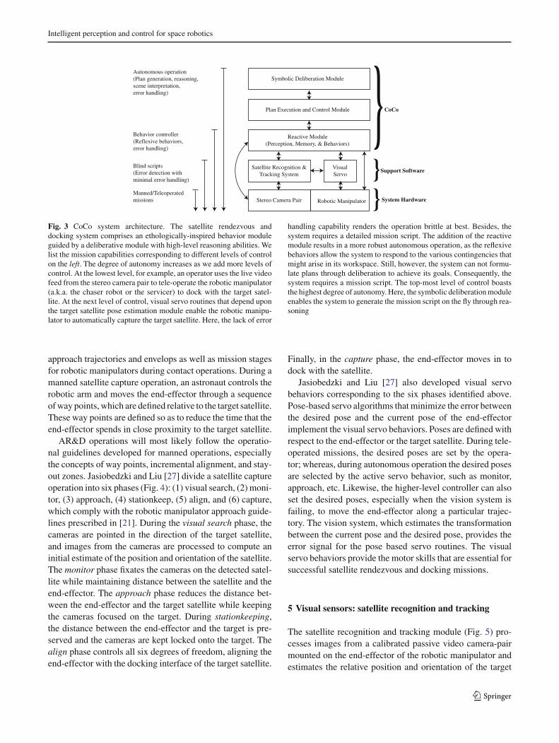
responsible for the immediate safety of the agent. As such,it functions competently on its own and runs at the highestpriority. At the intermediate level, the plan execution andmonitoring module establishes an adviser–client relationshipbetween the deliberative and reactive modules (Fig. 3).
In typical hybrid control frameworks, the reactive moduleserves as a mechanism to safely execute commands produ-ced through high-level reasoning [12,25] (a notable excep-tion is [6]). A reactive module is capable of much more asis shown by Tu and Terzopoulos [44], Blumberg [8], andArkin [7], among others. Agre and Chapman [2] observe thatmost of our daily activities do not require any planning what-soever; rather, deliberation occurs when a novel, previouslyunseen situation is encountered. This further highlights theimportance of a reactive module in any autonomous robot.CoCo features an ethologically inspired behavior based reac-tive system fashioned after those developed for autonomouscharacters in virtual environments [41,44].
In CoCo, the deliberative module advises the reactivemodule on a particular coarse of action through motivationalvariables. In contrast to other control architectures where thedeliberative module replaces the action selection mechanismbuilt into the reactive module [16], our approach provides astraightforward mechanism for providing high-level adviceto reactive behavior without interfering with the action selec-tion mechanism built into the reactive module.
Figure 2 illustrates the AR&D system realized within theCoCo framework. The satellite recognition and tracking rou-tines compute the position and orientation of the satellite andsupply the perceptual input to the reactive module, where theservo behaviors that control for the kinematic and dynamicactions of the robotic manipulator provide the relevant motorskills.
4 Motor skills: visual servo behaviors
Satellite rendezvous and docking operations, like all spacemissions, place stringent requirements on the safety of boththe astronauts and the equipment. Therefore, these missionsadhere to strict operational guidelines and fully scripted andrehearsed activities. The Mobile Servicing Systems Guidefor International Space Station Robotic Systems [21] defines
123
Intelligent perception and control for space robotics
Reactive Module(Perception, Memory, & Behaviors)
Plan Execution and Control Module
Symbolic Deliberation Module
Satellite Recognition &Tracking System
Robotic ManipulatorStereo Camera Pair
VisualServo
}}}
CoCo
System Hardware
Support Software
Manned/Teleoperatedmissions
Blind scripts(Error detection withminimal error handling)
Behavior controller(Reflexive behaviors,error handling)
Autonomous operation(Plan generation, reasoning,scene interpretation,error handling)
Fig. 3 CoCo system architecture. The satellite rendezvous anddocking system comprises an ethologically-inspired behavior moduleguided by a deliberative module with high-level reasoning abilities. Welist the mission capabilities corresponding to different levels of controlon the left. The degree of autonomy increases as we add more levels ofcontrol. At the lowest level, for example, an operator uses the live videofeed from the stereo camera pair to tele-operate the robotic manipulator(a.k.a. the chaser robot or the servicer) to dock with the target satel-lite. At the next level of control, visual servo routines that depend uponthe target satellite pose estimation module enable the robotic manipu-lator to automatically capture the target satellite. Here, the lack of error
handling capability renders the operation brittle at best. Besides, thesystem requires a detailed mission script. The addition of the reactivemodule results in a more robust autonomous operation, as the reflexivebehaviors allow the system to respond to the various contingencies thatmight arise in its workspace. Still, however, the system can not formu-late plans through deliberation to achieve its goals. Consequently, thesystem requires a mission script. The top-most level of control boaststhe highest degree of autonomy. Here, the symbolic deliberation moduleenables the system to generate the mission script on the fly through rea-soning
approach trajectories and envelops as well as mission stagesfor robotic manipulators during contact operations. During amanned satellite capture operation, an astronaut controls therobotic arm and moves the end-effector through a sequenceof way points, which are defined relative to the target satellite.These way points are defined so as to reduce the time that theend-effector spends in close proximity to the target satellite.
AR&D operations will most likely follow the operatio-nal guidelines developed for manned operations, especiallythe concepts of way points, incremental alignment, and stay-out zones. Jasiobedzki and Liu [27] divide a satellite captureoperation into six phases (Fig. 4): (1) visual search, (2) moni-tor, (3) approach, (4) stationkeep, (5) align, and (6) capture,which comply with the robotic manipulator approach guide-lines prescribed in [21]. During the visual search phase, thecameras are pointed in the direction of the target satellite,and images from the cameras are processed to compute aninitial estimate of the position and orientation of the satellite.The monitor phase fixates the cameras on the detected satel-lite while maintaining distance between the satellite and theend-effector. The approach phase reduces the distance bet-ween the end-effector and the target satellite while keepingthe cameras focused on the target. During stationkeeping,the distance between the end-effector and the target is pre-served and the cameras are kept locked onto the target. Thealign phase controls all six degrees of freedom, aligning theend-effector with the docking interface of the target satellite.
Finally, in the capture phase, the end-effector moves in todock with the satellite.
Jasiobedzki and Liu [27] also developed visual servobehaviors corresponding to the six phases identified above.Pose-based servo algorithms that minimize the error betweenthe desired pose and the current pose of the end-effectorimplement the visual servo behaviors. Poses are defined withrespect to the end-effector or the target satellite. During tele-operated missions, the desired poses are set by the opera-tor; whereas, during autonomous operation the desired posesare selected by the active servo behavior, such as monitor,approach, etc. Likewise, the higher-level controller can alsoset the desired poses, especially when the vision system isfailing, to move the end-effector along a particular trajec-tory. The vision system, which estimates the transformationbetween the current pose and the desired pose, provides theerror signal for the pose based servo routines. The visualservo behaviors provide the motor skills that are essential forsuccessful satellite rendezvous and docking missions.
5 Visual sensors: satellite recognition and tracking
The satellite recognition and tracking module (Fig. 5) pro-cesses images from a calibrated passive video camera-pairmounted on the end-effector of the robotic manipulator andestimates the relative position and orientation of the target
123

F. Qureshi, D. Terzopoulos
Fig. 4 Six phases during a satellite rendezvous and docking opera-tion [27]
Sparse 3DComputation
TargetDetection
Acquisition
Tracking
Target PoseEstimation and
Tracking
3D Satellite Model
3D Docking Interface Model
id, 3D pose
3D pose &motion
3D pose &motion
Monitoring3D Data
3D location, 3D motion
Calibrated StereoCameras Pair
Vision Serverid, 3D Pose, 3D motion, confidence
To CoCoís Reactive Module}Configuration Commands
Fig. 5 Satellite recognition and tracking system
satellite [24]. It supports medium and short range satelliteproximity operations; i.e., approximately from 6 to 0.2 m.The minimum distance corresponds to the separation bet-ween the camera and the satellite in contact position.
The vision algorithms implemented rely mostly on the pre-sence of natural image features and satellite models. Duringthe medium range operation, the vision system cameras vieweither the complete satellite or a significant portion of it (left
image in Fig. 6), and the system relies on natural featuresobserved in stereo images to estimate the motion and poseof the satellite. The medium range operation consists of thefollowing three configurations:
• Model-free motion estimation In the first phase, the visionsystem combines stereo and structure-from-motion toindirectly estimate the satellite motion in the camera refe-rence frame by solving for the camera motion, which isthe opposite of the satellite motion [37].
• Motion-based pose acquisition The second phaseperforms binary template matching to estimate the poseof the satellite without using prior information [18]. Itmatches a model of the observed satellite with the 3D dataproduced by the last phase and computes a six degree offreedom (DOF) rigid transformation that represents therelative pose of the satellite. The six DOFs are solved intwo steps. The first step, which is motivated by the obser-vation that most satellites have an elongated structure,determines the major axis of the satellite. The secondstep solves for the remaining four DOFs—the rotationaround the major axis and the three translations—throughexhaustive 3D template matching over the four DOFs.
• Model-based pose tracking The last phase tracks thesatellite with high precision and update rate by iterati-vely matching the 3D data with the model using a versionof the iterative closest point algorithm [23]. This schemedoes not match high-level features in the scene with themodel at every iteration. This reduces its sensitivity topartial shadows, occlusion, and local loss of data causedby reflections and image saturation. Under normal opera-tive conditions, model based tracking returns an estimateof the satellite’s pose at 2 Hz with an accuracy on theorder of a few centimeters and a few degrees.
The short range operation consists of one configuration,namely visual target based pose acquisition and tracking. Atclose range, the target satellite is only partially visible andit cannot be viewed simultaneously from both cameras (thecenter and right images in Fig. 6); hence, the vision systemprocesses monocular images. The constraints on the approachtrajectory ensure that the docking interface on the target satel-lite is visible from close range. Markers on the docking inter-face are used to determine the pose and attitude of the satelliteefficiently and reliably at close range [24]. Here, visual fea-tures are detected by processing an image window centeredaround their predicted locations. These features are then mat-ched against a model to estimate the pose of the satellite.The pose estimation algorithm requires at least four points tocompute the pose. When more than four points are visible,sampling techniques choose the group of points that gives thebest pose information. For the short range vision module, theaccuracy is on the order of a fraction of a degree and 1 mmright before docking.
123

Intelligent perception and control for space robotics
Fig. 6 Images from a sequencerecorded during an experiment(left image at 5 m; right at 0.2 m)
Fig. 7 Functionaldecomposition of the reactivemodule, which is realized as aset of asynchronous processes Action
Selection
Approach
Monitor
Align
Sen
sors
Vision
Attention
Misc.Sensors
Passage ofTime
Self-Motion
Projection
Mental State
AbstractedWorld State
Mo
tivat
ion
s
AW
S
Plan Executor & Monitoring Module
Perception center Memory center Behavior center
...
ReactiveModule
The vision system returns a 4 × 4 matrix that specifiesthe relative pose of the satellite, a value between 0 and 1quantifying the confidence in that estimate, and various flagsthat describe the state of the vision system.
The vision system can be configured on the fly depen-ding upon the requirements of a specific mission. It providescommands to activate/initialize/deactivate a particular confi-guration. At present this module can run in four differentconfigurations, which may run in parallel. Each configura-tion is suitable for a particular phase of the satellite servicingoperation and employs a particular set of algorithms. Activeconfigurations share the sensing and computing resources,which reduces the mass and power requirements of the visionsystem, but can adversely affect its overall performance.
6 The reactive module
CoCo’s reactive module is a behavior-based controller thatis responsible for the immediate safety of the agent. As such,it functions competently on its own and runs at the highestpriority. At each instant, the reactive module examines sen-sory information supplied by the perception system, as wellas the motivational variables whose values are set by thedeliberative module, and it selects an appropriate action. Itsselection thus reflects both the current state of the world andthe advice from the deliberative module. The second res-ponsibility of the reactive module is to abstract a continuumof low-level details about the world and present a tractablediscrete representation of reality within which the delibera-tive module can effectively formulate plans. CoCo’s reac-tive module comprises three functional units: perception,memory, and behavior (Fig. 7). This functional decomposi-
tion is intuitive and facilitates the design process. The reactivemodule is implemented as a collection of asynchronous pro-cesses (Table 1), which accounts for its real-time operation.
6.1 Perception center
From an implementational point of view, one can imaginetwo extremes: one in which a single process is responsiblefor computing every feature of interest, and the other inwhich every feature is assigned its own sensing process. Inthe first scenario, the overall speed of sensing is determinedby the feature that takes the longest time to compute, whe-reas a higher process management overhead is associatedwith the second scenario to ensure that the sensed values arecoherent. For a particular application, it is up to the designerto decide how best to implement the perception system. Wechose the second approach where various routines processdifferent perceptual inputs asynchronously in order to com-pute higher order features, which are then immediately avai-lable for subsequent processing. Each data item is assigneda timestamp and a confidence value between 0 and 1, and itis managed by the memory center, which is responsible forpreventing other processes from using outdated or incorrectinformation.2
The perception center manages the vision system whichwas described in Sect. 5. It decides which vision modulesto activate and how to combine the information from thesemodules depending on their characteristics, such as proces-sing times, operational ranges, and noise. In addition, the
2 Working memory is sometimes referred to as the short term memoryor STM.
123

F. Qureshi, D. Terzopoulos
Table 1 Four classes ofasynchronous processes(behaviors) constitute thereactive module
Class Input Output Functional unit
1 External External Behavior center (reflex actions)
2 External Internal Perception center (sensing)
3 Internal External Behavior center (motor commands)
4 Internal Internal Memory center (mental state maintenance)Behavior center (high level behaviors)Perception center (sensor fusion)
perception center incorporates an attention mechanism thatgathers information relevant to the current task, such as thestatus of the satellite chaser robot, the docking interface sta-tus, and the satellite’s attitude control status. The perceptioncenter processes the raw perceptual readings that appear at itsinputs, constructs appropriate perceptual features, and storesthem in the working memory (memory center) for later useby the behavior center during action selection and behaviorexecution. A perceptual reading is either from an actual phy-sical sensor (e.g., the docking interface sensor) or the resultof a multi-stage operation (e.g., the target satellite’s posi-tion and orientation). Each perceptual reading is processedindependently. Consequently, different perceptual featuresbecome available to the reactive module as soon as they arecomputed.
The perception center includes daemon processes forevery perceptual input (Figs. 8, 9). The daemon processes,which awaken whenever new information arrives at theirinput ports, assign a confidence value to the readings, times-tamp them, and push them up the perception pipeline forsubsequent processing. The confidence value for a reading isin the range [0, 1], where 0 reflects a total lack of confidenceand 1 reflects absolute certainty. It is computed either by theassociated daemon or by the process responsible for produ-cing the perceptual reading in the first place. For instance,the vision routines determine the confidence for the estima-ted position and orientation of the satellite and the daemonresponsible for the docking interface sensor assigns a valueof 1 to each new reading it receives from the sensor.
6.1.1 Communicating with the vision module
Figure 9 shows the interface to the vision sub-system. Longrange vision operates anywhere between 20 and 5 m, andthe maximum separation between the mock-up satellite androbotic arm is roughly 6 m. To estimate the position and orien-tation of the satellite, the perception center uses contextualinformation, such as the current task, the predicted distancefrom the target satellite, the operational ranges of the variousconfigurations, and the confidence values returned by theactive configurations. The perception center is responsiblefor the transitions between the different vision configura-tions, and it also performs a sanity check on the operation
Physical Sensors
DockingInterface
StatusAttitudeControl
Daemons
Enabled/disabled Ok/error Engaged/disengaged
WorkingMemory
<Value,Time,Confidence>
<Enabled,t,1.0> <Ok,t,1.0> <Engaged,t,1.0>
Passege ofTime
Passege ofTime
Passege ofTime
MemoryManagement
Fig. 8 Daemon processes for monitoring and reading satellite attitudecontrol, docking interface, and robotic arm status sensors. The daemonsthat collect information from the sensors are associated with the percep-tion center (bottom row), whereas those that operate upon the workingmemory belong to the memory center (top two rows)
of the vision sub-system. A decision about whether or not toaccept a new pose reading from an active vision module ismade by thresholding the confidence value of the reading.The minimum acceptable confidence value for a mediumrange estimate is 0.3 and it is 0.6 for a short range estimate.These threshold values reflect the expected performance cha-racteristics of the vision system and are selected to imposemore stringent performance requirements on the vision sys-tem when the robotic arm is in close proximity to the targetsatellite.
An αβ tracker validates and smoothes the pose readingsfrom the vision configurations (See [34] for details). Thevalidation is done by comparing the new pose against thepredicted pose using an adaptive gating mechanism. Whennew readings from the vision system consistently fail the vali-dation step, either the vision system is failing or the satelliteis behaving erratically and corrective steps are needed. Theαβ tracker thus corroborates the estimates of the visual rou-tines. In addition, it provides a straightforward mechanismfor compensating for visual processing delays by predictingthe current position and orientation of the target satellite.
123

Intelligent perception and control for space robotics
Vision system
MediumRange
ShortRange
Data validation& smoothing
(Pose,Status)Medium Range Module
(Pose,Status)Short Range Module
Fuzzy LogicSensorFusion
{ {
Passege ofTime
Target Pose, Confidence,Timestamp, Vision
system status { {
Fig. 9 The perception center is in charge of the vision system thatimplements satellite identification, recognition, and tracking routines.The deamon processes associated with the visual processing awakenswhen new vision readings become available and copy the new readingsinto the working memory. The vision readings are validated and smoo-thed using an αβ tracker. A fuzzy logic based sensor fusion schemecombines the readings when multiple vision configurations are active.A passage-of-time behavior associated with the satellite pose informa-tion implements a forgetting mechanism, which prevents the reactivesystem from using out-dated information
6.1.2 Visual processing handover
In the final stages of a successful satellite capture operation,the distance between the robotic arm and the target satellitecan vary anywhere from around 6–0 m. The perception cen-ter is responsible for transitioning the visual tracking taskfrom the medium to the short range module as the roboticarm approaches the target satellite and vice versa as it pullsback. The perception center uses the estimated distance ofthe target satellite and the confidence values returned by theactive vision configurations to decide which vision moduleto activate/deactivate.
The strategy for controlling the transition between mediumand short range vision modules is based on the followingintuitions:
• Since the vision modules are designed to perform reliablyonly in their operational ranges, a vision module whoseestimate falls outside of its operational range should notbe trusted.
• When the estimates returned by the active vision modulenears its operational limits, activate the more reliablevision module. The operational range of a vision moduleand the estimated distance of the target satellite deter-mines the suitability of the vision module. For example,when the medium range vision module is active and thetarget distance estimate is less than 2 m, the short range
vision module is activated. The short range vision moduleuses the current pose of the satellite as estimated by themedium range module to initialize satellite tracking.
• A vision module that is currently tracking the target satel-lite should not be deactivated unless another visionmodule has successfully initiated target tracking.
• Avoid unnecessary hand-overs.
We describe the hand-over strategy between differentvision modules in [34]. Figure 10 shows the operational sta-tus of the vision module during a typical satellite capturemission. Initially, the medium range vision module is tra-cking the target; however, as the robotic arm approaches thesatellite and the distance to the satellite decreases below 2 m,the short range module is activated. Once the short rangevision module successfully locks onto the satellite and com-mences visual tracking, the medium range vision module isdeactivated to conserve energy.
6.1.3 Target pose estimation using multiple visualprocessing streams
To improve the quality of target pose estimates and to ensuresmooth transition between different vision modules, we haveimplemented a fuzzy logic based sensor fusion scheme thatcombines pose estimates from active vision modules [34].The sensor fusion scheme takes into account target poseestimates along with their associated confidences and theoperational ranges of the vision modules to compute a weigh-ted sum of the pose estimates from the active modules.Currently, it works only with short and medium range visionmodules.3
The position p of the satellite is given by
p = wps + (1 − w)pm, (1)
where 0 ≤ w ≤ 1 is the weight assigned to the short-rangemodule’s estimate and which is determined by the fuzzy logicbased controller, and ps and pm are the position estimatesfor the short and medium range modules, respectively. Simi-larly, we combine the orientation estimates from the short andmedium range vision modules by expressing the orientationas quaternions and interpolating between them using w:
q = (qsq−1m )wqm, (2)
where qs and qm are the rotation estimates from the shortand medium range vision modules, respectively [34]. Whenw is 0 the computed pose of the target is the medium rangeestimate, whereas when w is 1, it is the estimate returned
3 The long range vision module is used only initially to locate and iden-tify the target. Once the target is identified, the medium range moduletakes over. At present, the long and medium range vision modules donot operate concurrently.
123

F. Qureshi, D. Terzopoulos
Fig. 10 a Medium range visionhands over target tracking to theshort range vision module as thechaser moves closer to thetarget. b The prediction error ofthe αβ tracker. The fuzzy logicbased sensor fusion schemefuses the information fromactive vision modules to form asingle coherent target poseestimate
0 50 100 150 200 250 300 350 400 450 5000
0.5
1
1.5
2
2.5
3
3.5
4
4.5
5
Time (sec)
Tar
get s
atel
lite
dist
ance
(m
)
Smoothing and validation using an α−β tracker
Vision system
α−β tracker
Short Range Vision
Medium Range Vision
0 50 100 150 200 250 300 350 400 450 5000
0.5
1
1.5
2
2.5
3x 10⁻³ Squared error (α−β tracker)
Time (sec)
Tar
get s
atel
lite
dist
ance
(m
)
(a) (b)
by the short range module. The details of the sensor fusionmodule are provided in [34].
6.2 Behavior center
The behavior center manages the reactive module’s behavio-ral repertoire. This by no means a trivial task involves arbitra-tion among behaviors. The reactive module supports multipleconcurrent processes, and arbitrates between them so thatthe emergent behavior is the desired one. We have, howe-ver, benefited from dividing the reactive module into threecomponents (perception, behavior, and memory), minimi-zing behavior-interaction across the components, thus sim-plifying the management of behaviors.
At each instant, the action selection mechanism choosesan appropriate high level behavior by taking into accountthe current state of the world and the motivations. The cho-sen action then activates lower level supporting behaviors,as necessary. The current state of the world takes precedenceover the motivations, i.e., the reactive module will follow theadvice from the deliberative module only when the condi-tions are favorable. When no motivation is available from thedeliberative module, the action selection mechanism simplychooses a behavior that is the most relevant, usually one thatensures the safety of the agent.
6.2.1 Motivational variables
The behavior controller maintains a set of internal mentalstate variables, which encode the motivations of the robo-tic arm: (1) search, (2) monitor, (3) approach, (4) align,(5) contact, (6) depart, (7) park, (8) switch, (9) latch, (10)sensor, and (11) attitude control. The mental state variablestake on values between 0 and 1, and at each instant the actionselection mechanism selects the behavior associated withthe motivational variable having the highest value. Priorityamong the different motivations resolves behavior selectionconflicts when multiple motivations have the same magni-tudes. Once the goal associated with a motivational variable is
fulfilled, the motivational variable begins to decrease asymp-totically to zero.4 A similar approach to action selection isused by Tu [44] in her artificial fish and by Shao [41] for hisautonomous pedestrians.
We model a level-of-interest to prevent one behavior fromexcluding other behaviors while it infinitely pursues an unat-tainable goal [8]. A maximum cutoff time is specified foreach motivational variable and if, for whatever reason, theassociated goal is not fulfilled within the prescribed cutofftime, the value of the motivational variable starts to decayto 0 (Fig. 11). We also employ a Minsky/Ludlow [29] modelof mutual inhibition to avoid behavior dither; a situationwhere the action selection keeps alternating between twogoals without ever satisfying either of them. Mutual inhi-bition is implemented by specifying a minimum duration forwhich a behavior must remain active and by initially increa-sing the value of the associated motivation variable (Fig. 12).
The values of the motivational variables are calculated asfollows:
mt =
⎧⎪⎪⎪⎪⎪⎨
⎪⎪⎪⎪⎪⎩
max(0, mt−1 − da∆t
(1 − dbm2
t−1
))
when t > tc or the associated behaviorachieves its goal,
min(
1, mt−1 + ga∆t(
em2t−1 − gb
))
when the associated behavior is first initiated,
where 0 ≤ ga ,gb,da ,db ≤ 1 are the coefficients that controlthe rate of change in the motivational variables, which are setempirically to 0.5, 0.99, 0.05, and 0.99, respectively.5 ∆t isthe time step. The values of a motivational variable at timet and t − ∆t are mt and mt−1, respectively. The associatedcutoff time is tc. The cutoff time for a particular motivation
4 This is consistent with the “drive reduction theory” proposed byHull [22], whose central theme is that drive (motivation) is essentialin order for a response to occur; furthermore, a response is chosen soas to reduce (or satisfy) the most pressing drive.5 In a more general setting the values of the coefficients can be chosenon a per-motivation basis.
123

Intelligent perception and control for space robotics
0
1
activ
e
0
1
time time
satis
fied
0 20 40 60 80 100 120 140 160 180
0 20 40 60 80 100 120 140 160 180
0 20 40 60 80 100 120 140 160 180
0 20 40 60 80 100 120 140 160 180
0
1monitor
valu
e
0
1
perc
eptu
alsu
ppor
t
activ
esa
tisfie
dva
lue
perc
eptu
alsu
ppor
t
0
1
0
1
0 20 40 60 80 100 120 140 160 180
0 20 40 60 80 100 120 140 160 180
0 20 40 60 80 100 120 140 160 180
0 20 40 60 80 100 120 140 160 180
0
1approach
0
1
(a) (b)
Fig. 11 Priority among motivations and level-of-interest modeling.The deliberative module sets the value of motivational variables moni-tor a and capture b to 1. The action selection mechanism selects themonitor behavior, which has a higher priority than the approach beha-vior. The monitor behavior fails to achieve its objectives within theprescribed time, the motivational variable monitor begins to decay to 0.
When the value of the monitor variable is less than that of the approachvariable, the approach behavior is activated. In this particular scenario,the approach behavior did not meet its objectives within the prescri-bed time and the approach variable decreases to zero. In either case,the decay in the motivational variables is due to the level-of-interestmodeling
Fig. 12 Mutual inhibition. Themonitor behavior has a higherpriority than the approachbehavior; however, when theapproach behavior is active, itinhibits the monitor behavior forsome prescribed time andprevents the monitor behaviorfrom becoming active. After theinhibition period, the monitorbehavior becomes active,deactivating the approachbehavior
0
1
activ
e
0
1
time time
satis
fied
0 20 40 60 80 100 120 140 160 180
0 20 40 60 80 100 120 140 160 180
0 20 40 60 80 100 120 140 160 180
0 20 40 60 80 100 120 140 160 180
0
1monitor
valu
e
0
1
perc
eptu
alsu
ppor
t
activ
esa
tisfie
dva
lue
perc
eptu
alsu
ppor
t
0
1
0
1
0 20 40 60 80 100 120 140 160 180
0 20 40 60 80 100 120 140 160 180
0 20 40 60 80 100 120 140 160 180
0 20 40 60 80 100 120 140 160 180
0
1approach
0
1
(a) (b)
depends upon two factors: the motivation in question andwhether or not other motivational variables are greater than 0:
tc ={
t1 when other motivational variables, > 0
t2 otherwise,
where 0 > t1 > t2 > ∞.The higher-level deliberative module suggests an action
to the reactive module by setting the relevant motivationalvariable(s) to 1 or 0. Any parameters associated with thesuggested action are passed directly to the behavior linked tothe motivational variable. It is up to the reactive module todecide whether or when to execute the suggested action byactivating the associated behavior. Furthermore, the reactivemodule is not responsible for communicating its decision orstatus to the deliberative module. The plan execution andmonitoring module determines whether or not the suggestedaction was ever executed or that it failed or succeeded throughthe abstracted world state (Fig. 13).
A consequence of the design proposed here is thatthe behavior-based reactive module is oblivious to the exis-tence of the deliberative and plan execution and monito-ring modules. The sole agenda of the reactive module is
to minimize the internal motivational variables by activa-ting appropriate behaviors. The system operates at a dimini-shed capacity when higher level modules are disabled. Builtinto the reactive module is a provision for overriding theaction selection mechanism during a teleoperated mission;i.e., when the system is being controlled by an astronaut.
6.3 Memory center
The memory center manages the short-term memory of theagent. It holds the relevant sensory information, motivations,state of the behavior controller, and the abstracted world state.At each instant, it copies whatever new sensory informationis available at the perception center, and it provides a conve-nient way of handling perception delays. At any moment,the memory center has a time-delayed version of the sensoryinformation, and it projects this information to the currentinstant. Thus, the behavior center need not wait for new sen-sory information; it can simply use the information storedin the memory center, which is responsible for ensuring thatthis information is valid.
The memory center uses two behavior routines (per fea-ture), self-motion and passage-of-time, to ensure the currency
123

F. Qureshi, D. Terzopoulos
Fig. 13 a Perceptual support:monitor behavior is deactivatedwhen perceptual support for themonitor behavior vanishes.b The approach behaviorinitially increases the approachvariable to encouragepersistence, and the approachvariable decreases as theapproach behavior is doing itsjob
0 50 100 1500
1
activ
e
0 50 100 1500
1
time
satis
fied
0 50 100 1500
1monitor
valu
e
0 50 100 1500
1
perc
eptu
alsu
ppor
t
activ
esa
tisfie
dva
lue
perc
eptu
alsu
ppor
t
0
1
0
1
time
0 50 100 150
0 50 100 150
0 50 100 150
0 50 100 150
0
1approach
0
1
(a) (b)
and coherence of the information. The robot sees its environ-ment egocentrically. External objects change their positionwith respect to the agent as it moves. The self-motion beha-vior routine constantly updates the internal world represen-tation to reflect the current position, heading, and speed ofthe robot.
Each perceptual feature is represented as a tuple 〈Value,Timestamp, Confidence〉 in the working memory. Value repre-sents the present value of the feature, Timestamp stores thetime at which the feature was generated, and Confidence ∈[0, 1] is the current confidence value of the feature. In theabsence of new readings from the perception center, the confi-dence in the world state should decrease with time (Fig. 14).How the confidence in a particular feature decreases dependson the feature (e.g., the confidence in the position of a dyna-mic object decreases more rapidly than that of a static object)and the penalty associated with acting on the wrong infor-mation.6
The ability to forget outdated sensory information is criti-cal to the overall operation of the reactive module, providinga straightforward mechanism to prevent it or the delibera-tive module from operating upon inaccurate, or worse, incor-rect information, and can be used to detect sensor failures.The confidence value for a perceptual feature tends to zeroin the absence of fresh information from the relevant sensor.The lack of new information from a sensor can be construedas a malfunctioning sensor, particularly for sensors, such asthe docking interface status sensor, that periodically send newinformation to the perception center.
6.3.1 Abstracted world state (AWS)
The reactive module requires detailed sensory information,whereas the deliberative module employs abstract informa-tion about the world. The memory center filters out unne-cessary details from the sensory information and generatesthe abstracted world state which expresses the world sym-bolically (Fig. 15). The abstracted world state is a discrete,
6 Decreasing confidence values over time is motivated by the decaytheory for short term (working) memory proposed by Peterson andPeterson in 1959 [32].
0 2 4 6 8 10 12 14 16 180
0.1
0.2
0.3
0.4
0.5
0.6
0.7
0.8
0.9
1
Con
fiden
ce [0
−1]
Time (seconds)
Satellite’s pose confidence varies over time
Supporting evidence increasesthe confidence
Confidence decreases inthe absence of new evidence
Processing Delay
Fig. 14 The confidence in the satellite’s pose decreases in the absenceof supporting evidence from the vision system
Satellite DistanceCaptured
1.5m 5m.5m
MediumNearClose Far
Satellite Pose Confidence
0 1
Capture
Monitor
GoodBad
Bad Good
0.80.67ActiveBehavior
Fig. 15 The abstracted world state represents the world symbolically.For example, the satellite is either Captured, Close, Near, Medium, orFar. In the memory center, the conversion from numerical quantities tosymbols takes into account the current state of the agent
multi-valued representation of an underlying continuousreality.
Discretization involves dividing a continuous variable intoranges of values and assigning the same discrete value to allvalues of the continuous variable that fall within a certainrange. Discretization, however, is not without its problems.When the value of the continuous variable hovers about a
123

Intelligent perception and control for space robotics
discretization boundary, the discretized value can switch backand forth between adjacent discrete values, which can posea challenge for a process that relies on the stability of a dis-crete variable. We address this problem by imitating hyste-resis during the discretization operation. We illustrate ourstrategy in Fig. 16a, where variable y resists a change fromα to β and vice-versa; thereby, avoiding alternating betweenthe two values when the value of x fluctuates about 0.5. Arelated approach is taken when converting binary (or dis-crete multi-valued) sensory information to binary (or multi-valued) fluents. Consider, for example, mapping a binaryvariable x ∈ [0, 1] to y ∈ [α, β],y =
{α if x = 0β if x = 1
.
The value of y does not faithfully follow the value of x .Rather, the value of y is only switched from α to β when
x
y
10 0.5 t
x1
0
y= y=
(a) (b)
Fig. 16 Emulating hysteresis during discretization. a y is a discreti-zation of x that takes values between 0 and 1. If y is α and the valueof x > 0.5 + ∆, y becomes β. Otherwise, if y is β and the value ofx < 0.5 − ∆, then y becomes α. b x ∈ [0, 1] is mapped to y ∈ [α, β].The state y = α indicates that x = 0 and y = β indicates that x = 1.The variable y resists changing its value from α to β and vice-versa,which allows y to exhibit more stable behavior by ignoring spuriouschanges in x
the value of x is consistently 1. Similarly, the value of y isswitched from β to α when the value of x stays at 0.
Using the above scheme, we convert continuous sensoryinformation, such as the estimated distance from the satelliteand the estimated speed of the satellite, as well as binaryvalues, such as the status of the latch, to appropriate fluentsthat comprise the abstracted world state. The list of fluents isprovided in Table 2.
7 The deliberative module
The deliberative module endows our agent with the abi-lity to plan its actions, so that it can accomplish high-leveltasks that are too difficult to carry out without “thinkingahead.” To this end, the deliberative module maintains a setof planners, each with its own knowledge base and plan-ning strategy. Generally, the world behaves much morepredictably at higher levels of abstraction. Hence, each plan-ner understands the world at an abstract level, which makesreasoning tractable, as opposed to ill-conceived attempts toformulate plans in the presence of myriad low-level details.The lowest level of abstraction for a particular planner isdetermined by the reactive module explicitly through theabstracted world state and implicitly through the behaviorsthat it implements. The latter constitute the basis (groundedactions) of the plans generated by the deliberative module.For any application, it is essential to choose the right level ofabstraction (Table 2).
Symbolic logic provides the right level of abstraction fordeveloping high level planners that elegantly express abs-tract ideas. We advocate using a high-level agent language,such as GOLOG [26], to develop planners for the deliberative
Table 2 The abstracted world state for the satellite servicing task
Fluents/arity Values Description
fStatus/1 On/off Status of the servicer
fSatPosConf/1 Yes/no Confidence in the estimated pose of the satellite
fSatPos/1 Near/medium/far/contact Distance from the satellite
fSatSpeed/1 Yes/no Whether the satellite’s relative speed is within the acceptable limits
fLatch/1 Unarmed/armed Status of the latch (docking interface)
fSatCenter/1 Yes/no Whether the satellite is in the center of the field of view
fSatAlign/1 Yes/no Whether servicer is aligned with docking interface of the satellite
fSensor/2 Short/medium, on/off Current configuration of the vision system
fError/1 Sensor/shadow/any/no Error status
fSatContact/1 False/true Whether satellite is already docked
fSatAttCtrl/1 On/off Whether or not the satellite’s attitude control is active
fSun/1 Front/behind Location of the Sun relative to the servicer
fRange/1 Near/far Distance from the satellite
The choice of fluents describing the abstracted world state depends upon the target application
123

F. Qureshi, D. Terzopoulos
Table 3 Primitive actions available to the planner that creates plans to accomplish the goal of safely capturing the target satellite
Actions/#args Arguments’ values Description
aTurnon/1 On/off Turns on the servicer
aLatch/1 Arm/disarm Enables/disables the latching mechanism
aErrorHandle/1 Informs the operator of an error condition
aSensor/2 Medium/near, On/off Configures the vision system
aSearch/1 Medium/near Initiates medium/short visual search sequence
aMonitor/0 Initiates monitor phase
aAlign/0 Initiates align phase
aContact/0 Moves in to make contact
aGo/3 Park/medium/near, Park/medium/near, Vis/mem Moves to a particular location using either current infor-mation from the vision system (if vision system is workingsatisfactorily) or relying upon the mental state
aSatAttCtrl/1 Off/on Asks ground station to turn off the satellite attitude control
aCorrectSatSpeed/0 Informs the operator that the satellite is behaving erratically
module. Consequently, the deliberative module compriseshigh-level, non-deterministic GOLOG programs whose exe-cution produce the plans for accomplishing the task at hand.GOLOG is a logic programming language for dynamicdomains with built-in primitives (fluents) to maintain anexplicit representation of the modeled world, on the basisof user supplied domain knowledge. The domain knowledgeconsists of what actions an agent can perform (primitiveaction predicates), when these actions are valid (preconditionpredicates), and how these actions affect the world (succes-sor state predicates). GOLOG provides high level constructs,such as if-then-else and non-deterministic choice, to specifycomplex procedures that model an agent and its environ-ment. A GOLOG program can reason about the state of theworld and consider various possible courses of action beforecommitting to a particular choice, in effect performing deli-beration. The GOLOG language has been shown to be wellsuited to applications in high-level control of robotic sys-tems, industrial processes, software agents, etc. An advantageof GOLOG over traditional programming languages like Cis that programs can be written at a much higher level ofabstraction. GOLOG is based on a formal theory of actionspecified in an extended version of the situation calculus [35],so GOLOG programs can be verified using theorem provingtechniques. A prototype GOLOG interpreter for SWI-Prolog[1] is presented in [34]. We treat GOLOG programs as plan-ners; hence, in the remainder of this paper we will use theterm planner and GOLOG program interchangeably.
The symbolic reasoning module comprises two specia-list planners. Planner A is responsible for generating plansto achieve the goal of capturing the target satellite. Plan-ner B attempts to explain the changes in abstracted worldstate. It effectively produces high level explanations of whatmight have happened in the scene (workspace). The primitiveactions available to the two planners are listed in Tables 3
and 4, respectively. The planners experience the worldthrough the fluents (AWS) listed in Table 2.
On receiving a request from the plan execution and moni-toring module, the deliberative module selects an appropriateplanner, updates the planner’s world model using the abstrac-ted world state, and activates the planner. The planner com-putes a plan, which is a sequence of zero (when the plannercannot come up with a plan) or more actions, to the delibe-rative module, which then forwards it to the plan executionand monitoring module. Each action of an executable plancontains execution instructions, such as which motivationalvariables to use, and specifies its preconditions and postcon-ditions.
7.1 Scene interpretation
The cognitive vision system monitors the progress of thecurrent task by examining the AWS, which is maintainedin real-time by the perception and memory module. Uponencountering an undesirable situation, the reasoning moduletries to explain it by constructing an interpretation. If thereasoning module successfully finds a suitable interpretation,it suggests appropriate corrective steps; otherwise, it suggests
Table 4 Primitive actions available to the planner that constructs abs-tract, high-level interpretations of the scene by explaining how the AWSis evolving
Actions/#args Arguments’ values Description
aBadCamera/0 Camera failure
aSelfShadow/0 Self-shadowing phenomenon
aGlare/0 Solar glare phenomenon
Sun/1 Front/behind The relative position of the Sun
aRange/1 Near/medium Distance from thesatellite
123

Intelligent perception and control for space robotics
the default procedure for handling anomalous situations. Thedefault error handling procedure for our application, like allspace missions, is to safely abort the mission, i.e., to bringthe robotic manipulator to its rest position while avoidingcollisions with the target satellite. The procedure for findingexplanations is as follows:
1: Construct plans that account for the current error condi-tions by using the knowledge encoded within the errormodel.
2: Sort these plans in ascending order according to theirlength. (We disregard the default plan, which usually hasa length of 1.)
3: for all Plans do4: Simulate plan execution; this consists of querying the
perception and memory unit or asking the operator.5: if The execution is successful then6: The current plan is the most likely explanation.7: Break8: end if9: end for
10: if No explanation is found then11: The default plan is the most likely explanation.12: end if13: Generate a solution based on the current explanation; this
requires another round of reasoning.14: if The solution corrects the problem then15: Continue doing the current task.16: else17: Abort the current task and request user assistance.18: end if
A fundamental limitation of the proposed scene interpre-tation strategy is that it requires a detailed error model—i.e.,a knowledge base of what might go wrong and how—andfor a general scene it might be infeasible to acquire thisknowledge. Space missions, however, can benefit from theapproach, since they are usually studied in detail for monthsand sometimes, years by a team of engineers and scien-tists who run through all the foreseeable scenarios. Indeed,on-orbit missions are carefully planned and highly scriptedactivities. Furthermore, they generally take place in unclut-tered environments, so the number of possible events can be
managed. Therefore, our framework appears to be useful forvision-based robotic systems for AR&D.
7.2 Cooperation between active planners
The planners cooperate to achieve the goal—safely captu-ring the satellite. The two planners interact through a planexecution and monitoring unit to avoid undesirable interac-tions. Upon receiving a new “satellite capture task” from theground station, the plan execution and monitoring moduleactivates Planner A, which generates a plan that transformsthe current state of the world to the goal state—a state wherethe satellite is secured. Planner B, on the other hand, is onlyactivated when the plan execution and monitoring moduledetects a problem, such as a sensor failure. Planner B gene-rates all plans that will transform the last known “good” worldstate to the current “bad” world state. Next, it determines themost likely cause for the current fault by considering eachplan in turn. After identifying the cause, Planner B suggestscorrections. In the current prototype. Possible correctionsconsist of “abort mission,” “retry immediately,” and “retryafter a random interval of time” (the task is aborted if thetotal time exceeds the maximum allowed time). Finally, afterthe successful handling of the situation, Planner A resumes(Tables 5, 6).
8 Plan execution and monitoring module
The Plan Execution and Monitoring (PEM) module inter-faces the deliberative and reactive modules. It initiates theplanning activity in the deliberative module when the user hasrequested the agent to perform some task, when the currentplan execution has failed, when the reactive module is stuck,or when it encounters a non-grounded action that requiresfurther elaboration. The execution is controlled through pre-conditions and postconditions specified by the plan’s actions.Together, these conditions encode plan execution controlknowledge. At each instant, active actions that have eithermet or failed their postconditions are deactivated, then un-executed actions whose preconditions are satisfied are activa-ted (Fig. 17). Together the preconditions and postconditionsconstitute the plan execution control knowledge.
Table 5 A linear plan generated by the GOLOG program to capture the target
Starting world state:fStatus(off) ∧ fLatch(unarmed) ∧ fSensor(all,off) ∧ fSatPos(medium) ∧ fSatPosConf(no) ∧ fSatCenter(no)
∧ fAlign(no) ∧ fSatAttCtrl(on) ∧ fSatContact(no) ∧ fSatSpeed(yes) ∧ fError(no)
Execution result:aTurnon(on) → aSensor(medium,on) → aSearch(medium) → aMonitor → aGo(medium,near,vis) →
aSensor(short,on) → aSensor(medium,off) → aAlign → aLatch(arm) → aSatAttCtrl(off) → aContact
The GOLOG program is provided in [34]
123

F. Qureshi, D. Terzopoulos
Table 6 Planner B uses the error model to determine possible expla-nations of an error condition
Starting world state:fRange(unknown) ∧ fSun(unknown) ∧ fSatPosConf(yes)
Proposed explanation 1: aBadCamera
Proposed explanation 2: aSun(front) → aGlare
Proposed explanation 3: aRange(near)→aSun(behind)→aSelfShadow
The plan execution and monitoring module executes these plans insequence to pick the most likely cause of the error. A solution is sug-gested once the cause of the error is identified
from previous action
Failed
Success
CheckPreconditions
Execute
Progress
Success
CheckPostconditions
Failed
to next action
Plan Failed
Plan FailedProgress
Grounded Action (Reactive Module)Conditional Action (Plan-execution Module)Heirarchical Action (Deliberative Module)
Fig. 17 The plan execution and monitoring module sequentially exe-cutes each action. It checks the current action’s preconditions untilthey succeed or fail. If they succeed, it enters the current action’sexecution/postcondition-check loop, wherein it activates the currentaction’s execution code until the postconditions either succeed or fail.Upon success, it proceeds to the next action
The PEM module can handle linear, conditional, and hie-rarchical plans; thereby, facilitating the sliding autonomycapability of the overall controller (Fig. 18). Plans construc-ted by the deliberative module have a linear structure. Everyaction of the plan is directly executable on the reactivemodule, and each action must succeed for the plan to achieveits objectives. Scripts uploaded by human operators usuallyhave a conditional/hierarchical structure. For conditionalplans, it is not sufficient to execute each action in turn, ratherthe outcome of an action determines which of the remainingactions to execute next. On the other hand, in hierarchicalplans some actions acts as macros that represent other plansthat have to be computed at runtime. The plan execution andmonitoring module handles linear, conditional, and hierar-chical plans through the following plan linearization process(Fig. 18):
1: if Current action is “grounded” (i.e., directly executableon the reactive module) then
go(l1,l2) pick(0) go(l2,l3) drop(())
Reactive Module
Suggesting a grounded action to the reactive module
PEM suggests a grounded action to thereactive module
go(l1,l2)
pick(0) go(l2,l3) drop(())
search(0) go(cur,l3) drop(())pick(0)
If O is at l2
go(l1,l2) search(0) go(cur,l3) drop(())pick(0)
Run-time linearization of conditional plan
PEM evaluates the condition, and the out-comedetermines which actions are chosen
go(l1,l2) go(l2,l3) drop(())
openhand closehandreach(0)
pick(0)
go(l1,l2) go(l2,l3) drop(())
Run-time completion of incomplete plans
At run-time, the PEM expands the non-groundedaction as a linear plan
(a)
(b)
(c)
Fig. 18 PEM module executing linear, conditional, and hierarchicalplans
2: Send to the reactive module.3: else if Current action is “conditional” (e.g., a sensing
action, etc.) then4: Evaluate condition and pick the next action based on
the outcome.5: else if Current action is “non-grounded” (i.e., it requires
further elaboration) then6: Perform elaboration and replace the hierarchical action
with the outcome (plan stitching).7: else8: Unknown action type. Plan execution failure.9: end if
The PEM module can execute multiple actions concur-rently; however, it assumes that the plan execution controlknowledge for these plans will prevent race conditions, dead-locks, and any undesirable side affects of concurrent execu-tion.
123

Intelligent perception and control for space robotics
8.1 Plan execution control knowledge
The PEM relies upon execution control knowledge to pro-perly execute a plan. Execution control knowledge is definedover the abstracted world state, and it consists of conditionsthat must hold before, during, or after an action (or a plan).Some of these conditions span the entire plan while othersare action-dependent. Together these conditions answer thefollowing questions that are vital for the correct executionof a plan:
• Plan validity (a plan might become irrelevant due to someoccurrence in the world).
• Action execution start time.• Now.• Later.• Never; the plan has failed.
• Action execution stop time.• Now; the action has either successfully completed or
failed.• Later; the action is progressing satisfactorily.
For our application, the plan execution control knowledgeis readily available in the form of precondition action axiomsand successor state axioms.
9 Results
We have developed and tested the CoCo AR&D system ina simulated virtual environment, as well as in a physical labenvironment at MDA Space Missions, Ltd., that faithfullyreproduces on-orbit movements and the illumination condi-tions of the space environment—strong light source, verylittle ambient light, and harsh shadows. The physical setupconsisted of the MD Robotics, Ltd., proprietary “ReuseableSpace Vehicle Payload Handling Simulator,” comprising twoFanuc robotic manipulators and the associated control soft-ware. One robot with the camera stereo pair mounted on itsend effector acts as the servicer. The other robot carries agrapple-fixture-equipped satellite mock-up and synthesizesrealistic satellite motion.
The capture procedure is initiated by a single high-levelcommand from the ground station. Upon receiving the com-mand, the system initializes the long-range vision moduleto commence a visual search procedure. Once the satelliteis found, and its identity confirmed, the system guides therobotic arm to move closer to the satellite. The performanceof the long-range vision module deteriorates as the separa-tion between the robotic arm and the satellite decreases dueto the fact that the cameras are mounted on top of the end-effector. In response, the cognitive vision system turns on themedium range vision module and it turns off the long-range
vision module to conserve power once the medium rangesystem is fully initialized and reliably tracking the satellite.Next, the robotic is arm tries to match the satellite’s linearand angular velocities, a procedure known as station kee-ping. Then, short-range vision processing is initiated, and amessage is sent to the ground station to turn off the satel-lite’s attitude control system. The robotic arm should notcapture a satellite whose attitude control system is functio-ning, as that might destroy the satellite, the robotic arm, orboth. When the attitude control system is inactive, the satel-lite begins to drift; however, the robotic arm follows it byrelying upon the short-range vision system. Upon receivinga confirmation from the ground station that the satellite’s atti-tude control system is off, the robotic arm moves in to makecontact.
We performed 800 test runs in the simulated environmentand over 25 test runs on the physical robots. For each run,we randomly created error conditions (see Table 7), such as avision system failure and/or hardware failures. The cognitivevision controller gracefully handled all of them and met itsrequirements; i.e., safely capturing the satellite using vision-based sensing (Fig. 6 shows example sensed images) whilehandling anomalous situations. The controller never jeopar-dized its own safety nor that of the target satellite. In mostcases, it was able to guide the vision system to re-acquirethe satellite by identifying the cause and initiating a sui-table search pattern. In situations where it could not resolvethe error, it safely parked the manipulator and informed theground station of its failure.
Figure 19 shows a satellite capture sequence in the lab,where the servicer was able to capture the satellite withoutincident.
During the capture sequence shown in Fig. 20, we simula-ted a vision system failure. The servicer gracefully handledthe error by relying upon its cognitive abilities and success-fully captured the satellite. When there is an error, such asa vision system failure, the reactive system responds imme-diately and tries to increase its separation from the satellite.In the absence any new perceptual information, the systemrelies upon its time-aware and context-sensitive mental state.Meanwhile, the deliberation module is using its knowledgebase to explain the error and suggest a recovery.
Figure 21 shows a simulated satellite rendezvous seque-nce. Upon receiving a dock command from the ground sta-tion, the servicer initiates a visual search behavior, whichpoints the cameras towards the incoming satellite (Fig. 21a,b).Once the satellite’s identity is confirmed, the servicer beginsto approach it (Fig. 21c). Initially, the servicer only has infor-mation about the position of the satellite; however, as itapproaches the satellite, it activates the medium visionmodule. The medium range vision processing estimatesthe orientation of the satellite. The servicer aligns itself withthe grapple fixture of the satellite, following an arc around
123

F. Qureshi, D. Terzopoulos
Table 7 CoCo handled theseerror conditions that wererandomly generated duringvarious test runs
Vision system errors Hardware errors
Camera failure Grapple fixture error
Self shadowing Joints error (critical)
Solar glare Satellite’s attitude control error
Failed transition between vision modules
Fig. 19 The servicer robotcaptures the satellite usingvision in harsh lightingconditions like those in orbit
Fig. 20 Despite a simulatedvision system failure, theservicer robot captures thesatellite using vision by makinguse of its cognitive abilities. Onthe right of each frame, we showthe view from the simulationenvironment that runs thecontroller code. The simulationenvironment communicates withthe physical robots over thenetwork. Here, the wireframerepresents the position of thesatellite as estimated by therobotic arm. The 3D model ofthe satellite represents the actualposition of the satelliteaccording to the sensors on theFanuc robot arm. The graycylinder represents the positionof the chaser robot end-effectoraccording to the telemeteryinformation. Note that theestimated position is maintainedin the absence new perceptualinformation (Frames 3 and 4).A vision failure was induced byshutting off the ambient light
(Frame 1) Recieved a capture command. (Frame 2) Target acquired.
(Frame 3) Approaching target. (Frame 4)Vision system failure.
(Frame 5) Safety manuever: departure. (Frame 6) Target re-aquired.
(Frame 7) Approaching target. (Frame 8) Aligning with the docking interface.
(Frame 9) Station keeping. (Frame 10) Moving in to make contact.
(Frame 11) Accounting for satellite drift. (Frame 12) Successful contact!
the satellite to avoid the delicate solar panels (Fig. 21d–f).The servicer initiates stationkeeping, where it matchesthe position and orientation of the satellite (Fig. 21g). Atthis stage, the servicer’s view is limited to the grapple fix-ture mounted on the satellite, as the cameras are mountedon the docking mechanism of the servicer. Therefore, theservicer activates the short range vision module. Finally, itmoves towards the satellite to make contact and capture it(Fig. 21h).
10 Conclusion
Like the earliest machine vision systems [31,36], futureapplications of vision will require more than just image ana-lysis. They will also need a high-level AI component to guidethe vision system in a deliberate, task-appropriate manner,to diagnose sensing problems, and to take corrective actions.The AI system must rely on a low-level reactive componentresponsible for sensorimotor control.
123

Intelligent perception and control for space robotics
Fig. 21 Satellite rendezvoussimulation
(a) Searching for the target. (b) Target identified; Long range vision.
(c) Moving towards the target. (d) Aligning with the docking interfacewhile avoiding the solar panels.
(e) Aligning with the docking interface. (f) Aligning with the docking interface.
(g) Making contact. (h) Target captured.
We have demonstrated such a system in the domain ofspace robotics, specifically in the context of on-orbit satelliteautonomous rendezvous and docking. Our practical vision-based robotic system interfaces object recognition andtracking with classical, logic-based AI through a behavior-based perception and memory unit. Using its reactive senso-rimotor and deliberative reasoning abilities, it successfullyperforms the complex task of autonomously capturing a free-orbiting satellite in harsh illumination conditions. In most ofour simulation tests as well as in a commercial robotic lab
environment that emulates the relevant real-world conditions,when prompted by a single high-level command our systemsuccessfully captured the target satellite while dealing withanomalous situations.
Acknowledgments The authors acknowledge the valuable technicalcontributions of P. Jasiobedzki, R. Gillett, H.K. Ng, S. Greene, J. Rich-mond, M. Greenspan, M. Liu, and A. Chan. This work was funded byMDA Space Missions, Ltd. (formerly MD Robotics, Ltd.) and PrecarnAssociates. We thank L. Gregoris for motivation, encouragement, andsupport.
123

F. Qureshi, D. Terzopoulos
References
1. Swi-prolog. http://www.swi-prolog.org/2. Agre, P., Chapman, D.: Pengi: an implementation of a theory of
activity. In: Proceedings of American Association of ArtificialIntelligence, San Mateo, CA. Morgan Kaufmann (1987)
3. Arens, M., Nagel, H.H.: Behavioral knowledge representation forthe understanding and creation of video sequences. In: Gunther,A., Kruse, R., Neumann, B. (eds), Proceedings of the 26thGerman Conference on Artificial Intelligence (KI-2003), pp. 149–163, Hamburg, Germany (15–18 September 2003)
4. Arens, M., Ottlik, A., Nagel, H.-H.: Natural language texts for acognitive vision system. In: van Harmelen, F. (ed), Proceedings ofthe 15th European Conference on Artificial Intelligence (ECAI-2002), pp. 455–459, Amsterdam, The Netherlands. IOS Press(21–26 July 2002)
5. Arkin, R.C.: AuRA: a hybrid reactive/hierarchical robot archi-tecture. In: Proceedings of the IEEE International Conference onRobotics and Automation, Workshop on Architecture for Intelli-gent Control Systems, 1992
6. Arkin, R.C., Riseman, E.M., Hanson, A.R.: ArRA: An archi-tecture for vision-based robot navigation. In: Proceedings ofthe DARPA Image Understanding Workshop, Los Angeles, CA(1987)
7. Arkin, R.C., Fujita, M., Takagi, T., Hasegawa, R.: Ethologicalmodeling and architecture for an entertainment robot. In: Pro-ceedings of the 2001 IEEE International Conference on Roboticsand Automation (ICRA 2001), pp. 453–458, Seoul, South Korea.IEEE, (2001)
8. Blumberg, B.M.: Action selection in hamsterdam: lessons fromethology. In: Proceedings of the third International Conference onthe Simulation of Adaptive Behaviour, Brighton. The MIT Press,Cambridge (1994)
9. Brooks, R.A.: A layered intelligent control system for a mobilerobot. In: Faugeras, O.D., Giralt, G. (eds.) Robotics Research, TheThird International Symposium. MIT press, (1986)
10. Brookshire, J., Singh, S., Simmons, R.: Preliminary results in sli-ding autonomy for assembly by coordinated teams. In: Procee-dings IEEE/RSJ International Conference on Intelligent Robotsand Systems (IROS 2004), pp. 706–711 (2004)
11. Burgard, W., Cremers, A.B., Fox, D., Hahnel, D., Lakemeyer, G.,Schulz, D., Steiner, W., Thrun, S.: Experiences with an interactivemuseum tour-guide robot. Artif. Intell. 114(1–2), 3–55 (1999)
12. Connell, J.: SSS: A hybrid architecture applied to robot navigation.In: Proceedings of the IEEE International Conference on Roboticsand Automation (1992)
13. Davinic, N., Arkus, A., Chappie, S., Greenberg, J.: Cost-benefitanalysis of on-orbit satellite servicing. J. Reducing Space MissionCost 1(1), 27–52 (1988)
14. Fernyhough, J., Cohn, A.G., Hogg, D.C.: Constructing qualita-tive event models autmatically from video input. Image VisionComput. 18, 81–103 (2000)
15. Funge, J., Tu, X., Terzopoulos, D.: Cognitive modeling: Know-ledge, reasoning and planning for intelligent characters. In:Rockwood, A. (ed.), Proceedings of the Conference on ComputerGraphics (Siggraph99), NY. ACM Press, NewYork (8–13 August1999)
16. Gat, E.: Integrating planning and reacting in a heterogeneous asyn-chronous architecture for controlling real-world mobile robots.In: Proceedings of Tenth National Conference on Artificial Intel-ligence, Menlo Park, CA, USA (1992)
17. Gillett, R., Greenspan, M., Hartman, L., Dupuis, E., Terzopou-los, D.: Remote operations with supervised autonomy (rosa).In: Proceedings 6th International Symposium on Artificial Intel-
ligence, Robotics and Automation in Space (ISAIRAS ’01),Montreal (2001)
18. Greenspan, M., Jasiobedzki, P.: Pose determination of a free-flyingsatellite. In: Motion Tracking and Object Recognition (MTOR02),Las Vegas, NV (24–27 June 2002)
19. Gurtuna, O.: Emerging space markets: engines of growth for futurespace activities (2003). http://www.futuraspace.com/EmergingSpaceMarkets_fact_sheet.htm.
20. Howarth, R.J., Buxton, H.: Conceptual descriptions from monito-ring and watching image sequences. Image Vis. Comput. 18, 105–135 (2000)
21. Mobile Servicing System (MSS) to User (Generic) InterfaceControl Document (1997) http://www.spaceref.com
22. Hull, C.: Principles of behavior. Appleton–Century–Crofts, NewYork (1943)
23. Jasiobedzki, P., Greenspan, M., Roth, G.: Pose determination andtracking for autonomous satellite capture. In: Proceedings ofthe sixth International Symposium on Artificial Intelligence andRobotics & Automation in Space (i-SAIRAS 01), Montreal,Canada (2001)
24. Jasiobedzki, P., Greenspan, M., Roth, G., Ng, H.K., Witcomb, N.:Video-based system for satellite proximity operations. In: seventhESA Workshop on Advanced Space Technologies for Roboticsand Automation (ASTRA 2002), ESTEC, Noordwijk, The Nether-lands (19–21 November 2002)
25. Jenkin, M., Bains, N., Bruce, J., Campbell, T., Down, B.,Jasiobedzki, P., Jepson, A., Majarais, B., Milios, E., Nickerson, B.,Service, J., Terzopoulos, D., Tsotsos, J., Wilkes, D.: Ark: autono-mous mobile robot for an industrial environment. In: ProceedingsIEEE/RSJ International Conference on Intelligent Robots andSystems (IROS ’94), pp. 1301–1308, Munich, Germany (1994)
26. Lespérance, Y., Reiter, R., Lin, F., Scherl, R.: GOLOG: a logicprogramming language for dynamic domains. J. Logic Progr. 31(1–3), 59–83 (1997)
27. Liu, M., Jasiobedzki, P.: Behaviour based visual servo controllerfor satellite capture. In: Proceeding 7th ESA Workshop on Advan-ced Space Technologies for Robotics and Automation (ASTRA2002), (19–21 November 2002)
28. Middleton, R., Waltz, D., Schrock, S. (eds.) Satellite Servi-cing Technology Development Missions, Cocoa Beach, FL, USA(26–28 April 1984)
29. Minsky, M.: The Society of Mind. Simon and Schuster, Inc.,New York (1985)
30. Jet Propulsion Labs, NASA: Mars exploration rover missionhome (2004). http://www.marsrovers.nasa.gov
31. Nilsson, N.J.: Shakey the robot. Technical Report 323, ArtificialIntelligence Center. SRI International, USA (1984)
32. Peterson, L.R., Peterson, M.J.: Short-term retention of individiualverbal items. J. Exp. Psychol. 58(3), 193–198 (1959)
33. Polites, M.: An assessment of the technology of automated ren-dezvous and capture in space. Technical Report NASA/TP-1998-208528, Marshall Space Flight Center, Alabama, USA (1998)
34. Qureshi, F.: Intelligent Perception in Virtual Sensor Networks andSpace Robotics. PhD thesis, University of Toronto (2006, in pre-paration)
35. Reiter, R.: Knowledge in Action—Logical Foundations for Spe-cifying and Implementing Dynamical Systems. The MIT Press,Cambridge (2001)
36. Roberts, L.: Machine perception of 3-D solids. In: Trippit, J.T.,Berkowitz, D.A., Chapp, L.C., Koester, C.J., Vanderburgh, A.(eds.) Optical and Electro-Optical Information Processing. pp.159–197. MIT Press, New York (1965)
37. Roth, G., Whitehead, A.: Using projective vision to find camerapositions in an image sequence. In:Vision Interface (VI 2000), pp.87–94, Montreal, Canada (14–17 May, 2000)
123
Intelligent perception and control for space robotics
38. Sacerdoti, E.D.: Planning in a hierarchy of abstraction spaces.Artif. Intell. 5(2) (1974)
39. Sacerdoti, E.D.: The nonlinear nature of plans. In: Proceedings ofthe Fourth International Joint Conference on Artificial Intelligence(1975)
40. Sellner, B., Hiatt, L., Simmons, R., Singh, S.: Attaining situatio-nal awareness for sliding autonomy. In: Proceedings first AnnualConference on Human–Robot Interaction (HRI2006), Salt LakeCity, Utah, USA (2006)
41. Shao, W., Terzopoulos, D.: Autonomous pedestrians. In: Procee-dings ACM SIGGRAPH/Eurographics Symposium on ComputerAnimation, pp. 19–28, Los Angeles, CA (2005)
42. Terzopoulos, D., Tu, X., Grzeszczuk, R.: Artificial fishes withautonomous locomotion, perception, behavior, and learning in asimulated physical world. In: Brooks, R.A., Maes, P. (eds.) Pro-ceedings of the fourth International Workshop on the Synthesisand Simulation of Living Systems Artificial Life IV, Cambridge,MA, USA MIT Press, Cambridge (1994)
43. Tsotsos, J.K.: A ‘complexity level’ analysis of immediate vision.International Journal of Computer Vision 2(1), 303–320 (1988)
44. Tu, X., Terzopoulos, D.: Artificial fishes: physics, locomotion,perception, behavior. In: Proceedings of SIGGRAPH ’94, Compu-ter Graphics Proceedings, Annual Conference Series. ACM SIG-GRAPH, ACM Press (1994) ISBN 0-89791-667-0
45. Wertz, J., Bell, R.: Autonomous rendezvous and docking techno-logies—status and prospects. In: SPIE’s 17th Annual Internatio-nal Symposium on Aerospace/Defense Sensing, Simulation, andControls, Orlando, FL (21–25 April 2003)
Author biographies
Faisal Qureshi obtained a PhDin Computer Science from theUniversity of Toronto in 2007.He also holds an M.Sc. in Com-puter Science from the Univer-sity of Toronto, and an M.Sc.in Electronics from Quaid-e-Azam University, Pakistan. Hisresearch interests include sensornetworks, computer vision, andcomputer graphics. He has alsopublished papers in space robo-tics. He has interned at ATR Labs(Kyoto, Japan), AT&T ResearchLabs (Red Bank, NJ, USA), and
MDA Space Missions (Brampton, ON, Canada). He is a member of theIEEE and the ACM.
Demetri Terzopoulos is theChancellor’s Professor of Com-puter Science at the Universityof California, Los Angeles. Hegraduated from McGill Univer-sity and obtained a PhD degreein MIT in 1984. He is a fellow ofthe IEEE, a fellow of the RoyalSociety of Canada, and a mem-ber of the European Academyof Sciences. His many awardsinclude an academy award fortechnical achievement from theAcademy of Motion Picture Artsand Sciences for his pioneering
work on physics-based computer animation. He is one of the most highlycited computer scientists and engineers in the world, with approxima-tely 300 published research papers and several volumes, primarily incomputer graphics, computer vision, medical imaging, computer-aideddesign, and artificial intelligence/life.
123