Embed Size (px)
Citation preview

1/16
Sage KokjohnEngine Research Center
University of Wisconsin - Madison
Intelligent Integration of Electric Motors and Engines
Work based on funding from:This material is based upon work supported by the U.S. Department of Energy’s Office of Energy Efficiency and Renewable Energy (EERE) under the Transportation Offices –Vehicle Technologies, Fuel Cell Technologies, and Bioenergy Technologies programs Award Number DE-EE0008801

2/16
Outline
• Engine Research Center (ERC) overview• Overview of DOE hybrid project
– Typical off-highway powertrains and challenges
– Electrification of air-handling– Electrification of torque actuation
• Summary

3/16
Engine Research Center Overview
• The Engine Research Center (ERC) was established in 1946 by Profs. Myers and Uyehara, who were joined by Prof. Borman in 1970.
• Over the 70 years of its existence, the ERC has pioneered:– in-cylinder measurements of gas temperature, composition and heat flux– the simulation of turbulent, multi-phase, reacting flows in reciprocating
engines– high efficiency, low-emissions combustion strategies such as RCCI and
HCCI
• Current ERC has 5 active faculty, 3 emeritus faculty, and ~50 graduate students, post-docs, and scientists
ChrisRutland Mario
TrujilloSage
KokjohnScott
SandersDavid
RothamerJaal
Ghandhi
ERC Emeritus Faculty ERC Faculty

4/16
Engine Research Center Overview
• ERC Research Projects

5/16
Overview of DOE Hybrid Project
Team member Location Role in project
UW – Madison Engine Research Center
Madison, WI Program Lead Combustion System Development
UW – Madison Wisconsin Electric Machines and Power Electronics Consortium
Madison, WI Electric Machine Development
John Deere Cedar Falls, IA System Integration
Purdue University West Lafayette, IN Powertrain Controls
• Recently started a new program with DOE focused on hybridization of off-highway vehicles
• Joint program between UW-ERC, WEMPEC, John Deere, and Purdue University

6/16
Overview of Off-Highway Vehicle Powertrains
Baseline powertrain• Turbo-charged diesel engine• Hydraulic or mechanical
transmission• High pressure (>2000 bar)
common-rail fuel system• Suite of emissions control
– Cooled exhaust gas recirculation (EGR) à in-cylinder NOx control
– Selective catalytic reduction (SCR) à controls NOx in the exhaust
– Diesel particulate filter (DPF) àcaptures soot in the exhaust
– Hydrocarbon, carbon monoxide, and ammonia slip catalysts

7/16
Off-highway Vehicle Challenges
• Transient duty-cycle requires rapid torque response – Engine is often oversized to accommodate torque acceptance– Turbine is sized for transient response, resulting in increased
back pressure at high flow conditions à decreased efficiency
• “Passive” control of air-handling results in upload soot “spikes” and download NOx “spikes”
• Periods of low-load operation require after-treatment thermal management (i.e., using fuel to keep the aftertreatment warm without performing work)
• Integration of electric motors and engines may mitigate these challenges while retaining the required energy density for operation in remote environments

8/16
Improved Air Handling through Electrification
• Electric supercharger– Located in parallel with existing turbocharger and used to provide additional
air-flow to help spool turbo– Energy recovery is possible, but has substantial losses– System simulations show a substantial improvement in transient response– Efficiency improvement requires system architecture changes enabled by
improved air control (e.g., downsizing)

9/16
Improved Air Handling through Electrification
• Electric turbocharger– High speed > 50,000 rev/min electric motor coupled to turbo-shaft– Natural operation in both powering and energy recovery modes– 48V and higher voltage systems are common
Discharge
Charge

10/16
Soot Reduction using E-Turbo
• E-turbo’s improved control over air-flow expected to reduce transient soot by avoiding operation at low AFR
• Assessed using one-dimensional fluid dynamics modeling over a load step from 50 to 400 N-m
• E-turbo uses exhaust air-fuel ratio feedback to minimize operation at low AFR (conducive to soot formation)
• Results show– 33% reduction in transient soot– Estimated 1.4% reduction in fuel
consumption due to reduced DPF regeneration penalty
11/16
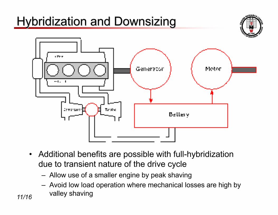
Hybridization and Downsizing
• Additional benefits are possible with full-hybridization due to transient nature of the drive cycle– Allow use of a smaller engine by peak shaving– Avoid low load operation where mechanical losses are high by
valley shaving

12/16
Hybridization and Downsizing
• Baseline engine: 6.8 L Tier 4 final engine with a peak torque of 1057 N-m (BMEP = 19.5 bar)
• Peak load of downsized (4.5 L) engine constrained to 19.5 bar BMEP
• Non-road transient cycle (NRTC) simulated– Engine provides torque from 200 N-m to
700 N-m– Charging below 200 N-m– Motor provides torque above 700 N-m– NOx constant at 0.4 g/kW-hr– Battery SOC forced to return to initial value
at the end of the cycle
• 4% reduction in fuel consumption at equal DEF consumption

13/16
Energy Recovery using E-Turbo• E-turbo used in conjunction with
hybridization allows recovered energy to be used as torque demand
• One-dimensional fluid dynamics model used to evaluate energy recovery using the e-turbo
• E-turbo was set to absorb power from the exhaust by targeting an air-fuel ratio 2 to 5 points below the steady-state air fuel ratio
• ~2.7% reduction in fuel consumption

14/16
Combined System Benefits• System analysis shows pathway to > 10% increase in efficiency

15/16
Summary
• Substantial potential for improvement in off-highway vehicle efficiency through hybridization
• System analysis shows a pathway to >10% reduction in fuel consumption– Downsizing– Energy recovery– Reduced soot penalty– Reduced catalyst heating penalty
• Engine and in-vehicle demonstration planned

17/16
Reducing the Catalyst Heating Penalty• SCR equipped engines have a fuel
consumption penalty at low load conditions due to the requirement to keep the catalyst temperature above ~200° to 250° C to allow urea dosing.
• E-turbo can be used to control catalyst inlet temperature to keep the catalyst warm while minimizing the fuel consumption penalty
• Application of e-turbo shows– 18% reduction in fuel
consumption during catalyst heating or “stay warm” operation
– Estimated reduction in NRTC fuel consumption of 2.7%